WO2020031788A1 - 電子機器 - Google Patents
電子機器 Download PDFInfo
- Publication number
- WO2020031788A1 WO2020031788A1 PCT/JP2019/029837 JP2019029837W WO2020031788A1 WO 2020031788 A1 WO2020031788 A1 WO 2020031788A1 JP 2019029837 W JP2019029837 W JP 2019029837W WO 2020031788 A1 WO2020031788 A1 WO 2020031788A1
- Authority
- WO
- WIPO (PCT)
- Prior art keywords
- magnetic device
- dea
- magnetic
- dielectric elastomer
- elastomer actuator
- Prior art date
- Legal status (The legal status is an assumption and is not a legal conclusion. Google has not performed a legal analysis and makes no representation as to the accuracy of the status listed.)
- Ceased
Links
Images








Classifications
-
- G—PHYSICS
- G06—COMPUTING OR CALCULATING; COUNTING
- G06F—ELECTRIC DIGITAL DATA PROCESSING
- G06F3/00—Input arrangements for transferring data to be processed into a form capable of being handled by the computer; Output arrangements for transferring data from processing unit to output unit, e.g. interface arrangements
- G06F3/01—Input arrangements or combined input and output arrangements for interaction between user and computer
-
- G—PHYSICS
- G06—COMPUTING OR CALCULATING; COUNTING
- G06F—ELECTRIC DIGITAL DATA PROCESSING
- G06F3/00—Input arrangements for transferring data to be processed into a form capable of being handled by the computer; Output arrangements for transferring data from processing unit to output unit, e.g. interface arrangements
- G06F3/01—Input arrangements or combined input and output arrangements for interaction between user and computer
- G06F3/02—Input arrangements using manually operated switches, e.g. using keyboards or dials
-
- H—ELECTRICITY
- H02—GENERATION; CONVERSION OR DISTRIBUTION OF ELECTRIC POWER
- H02N—ELECTRIC MACHINES NOT OTHERWISE PROVIDED FOR
- H02N11/00—Generators or motors not provided for elsewhere; Alleged perpetua mobilia obtained by electric or magnetic means
Definitions
- the present disclosure relates to an electronic device including a dielectric elastomer actuator.
- Patent Literature 1 discloses a diaphragm valve including a film-like dielectric elastomer actuator, a base material that supports the dielectric elastomer actuator, and an elastic member that elastically biases the dielectric elastomer actuator.
- a voltage is applied to the dielectric elastomer actuator of the diaphragm valve in the open state, the dielectric elastomer actuator expands in the surface direction and is pushed down so as to cover the orifice by the biasing force of the elastic member.
- the diaphragm valve switches from the open state to the closed state.
- An object of the present disclosure is to improve design flexibility in an electronic device including a dielectric elastomer actuator.
- An electronic device that solves the above-mentioned problem is a film-like dielectric elastomer actuator, a base material that supports the dielectric elastomer actuator, a first magnetic device attached to the base material, A second magnetic device that generates repulsion or attraction between the first magnetic device and the first magnetic device.
- the repulsive force or attractive force generated between the magnetic device attached to each of the dielectric elastomer actuator and the substrate is used as the urging means for urging the dielectric elastomer actuator.
- the first magnetic device and the second magnetic device are separated from each other, and a space is formed between the first magnetic device and the second magnetic device.
- the component is at least one of the base material, the wiring, the contact point of the switch, and the bag body surrounding the dielectric elastomer actuator.
- the electronic device further includes an adjustment mechanism that adjusts a distance between the first magnetic device and the second magnetic device.
- the output of the dielectric elastomer actuator can be adjusted by changing the repulsive force or attractive force generated between the first magnetic device and the second magnetic device (biasing force on the dielectric elastomer actuator).
- the first magnetic device is detachably attached to the base.
- the output of the dielectric elastomer actuator can be changed by replacing the biasing means for biasing the dielectric elastomer actuator. Then, the work space required for making the change can be reduced, and the device can be downsized.
- the first magnetic device and the second magnetic device are used as the urging means, the first magnetic device is detached and attached to the base while the second magnetic device is kept as it is. Just do the work. Therefore, there is no need to secure a work space required for the work of removing and attaching the second magnetic device, and the work space can be reduced.
- the second magnetic device generates a repulsive force between the second magnetic device and the first magnetic device.
- the operation of the dielectric elastomer actuator can be efficiently converted to a pseudo force sense (tactile sensation) presented to the user.
- the electronic device further includes a ferromagnetic shielding member provided on a side of the second magnetic device opposite to the first magnetic device, and covering the second magnetic device.
- the shielding member covers a side surface of the second magnetic device.
- the second magnetic device since the side surface of the second magnetic device is covered with the shielding member in addition to the portion of the second magnetic device opposite to the side of the first magnetic device, the second magnetic device is generated from the side surface of the second magnetic device.
- the magnetic flux penetrating through the film surface of the dielectric elastomer actuator can be reduced.
- generation of an eddy current on the film surface due to the magnetic flux can be suppressed.
- the electronic device further includes a shielding member made of a ferromagnetic material that is provided around a side surface of the second magnetic device and covers the second magnetic device.
- a shielding member made of a ferromagnetic material that is provided around a side surface of the second magnetic device and covers the second magnetic device.
- the second magnetic device is attached to a surface of the dielectric elastomer actuator on the first magnetic device side. According to the above configuration, since the second magnetic device is attached to the surface of the dielectric elastomer actuator on the first magnetic device side, a repulsive force or attractive force is effectively generated between the first magnetic device and the second magnetic device. Can be done.
- the shielding member is a first shielding member
- the electronic device is provided on a side of the first magnetic device opposite to the second magnetic device, and covers the first magnetic device. It is preferable to further include a second shielding member made of a body.
- the portion of the first magnetic device opposite to the second magnetic device side is covered with the second shielding member.
- the magnetic flux penetrating through the film surface can be reduced.
- generation of an eddy current on the film surface due to the magnetic flux can be suppressed.
- the shielding member is a first shielding member
- the electronic device is provided around a side surface of the first magnetic device, and is a second shielding member made of a ferromagnetic material that covers the first magnetic device. It is preferable to further include
- the second shielding member includes a side wall provided around a side surface of the first magnetic device and covering the first magnetic device. According to the above configuration, since the side surface of the first magnetic device is covered with the second shielding member, it is possible to reduce the magnetic flux penetrating the film surface of the dielectric elastomer actuator among the magnetic flux generated from the side surface of the first magnetic device. Can be. Thus, generation of an eddy current on the film surface due to the magnetic flux can be suppressed.
- the first magnetic device is configured to be movable or replaceable.
- the first magnetic device is configured to be movable or replaceable.
- the repulsive or attractive force generated between the first magnetic device and the second magnetic device by moving the first magnetic device or replacing the first magnetic device with one having a different magnetism (biasing force on the dielectric elastomer actuator) ),
- the output of the dielectric elastomer actuator can be adjusted.
- the electronic device includes a movable member that can move relative to the base material, and the first magnetic device is attached to the movable member. According to the above configuration, the first magnetic device can be easily moved to an arbitrary position by displacing the movable member.
- the first magnetic device is one of a plurality of first magnetic devices having different magnetisms, and the plurality of first magnetic devices are attached to the movable member. It is preferable that the first magnetic device located at a specific position based on the position of the second magnetic device can be changed by displacing the movable member.
- the base member includes an attachment portion for detachably attaching the first magnetic device, and the attachment portion is provided on a portion of the base member opposite to a side facing the dielectric elastomer actuator. Preferably, it is provided.
- the dielectric elastomer actuator when replacing the first magnetic device attached to the mounting portion, the dielectric elastomer actuator is less likely to become an obstacle, and the first magnetic device can be easily replaced.
- the second magnetic device generates a repulsive force between the second magnetic device and the first magnetic device.
- the operation of the dielectric elastomer actuator can be efficiently converted to a pseudo force sense (tactile sensation) presented to the user.
- the electronic device further includes a plate-shaped base, the base is detachably provided to the base from the front side of the base, and the dielectric elastomer actuator is supported by the base on the front side of the base. It is preferable that the first magnetic device is disposed on the back side of the base.
- the second magnetic device generates a repulsive force between the second magnetic device and the first magnetic device.
- the operation of the dielectric elastomer actuator can be efficiently converted to a pseudo force sense (tactile sensation) presented to the user.
- the base member is a button body of a push button type switch, and the switch opens and closes an electric circuit in accordance with a pressing operation of the button body with respect to the base, and the dielectric elastomer actuator
- a transmission unit for transmitting a force based on the operation of the dielectric elastomer actuator to the button body is provided.
- the button body that supports the dielectric elastomer actuator is detachably provided to the base, the button body can be removed without removing the first magnetic device disposed on the back side of the base. it can. This makes it possible to easily replace the dielectric elastomer actuator.
- the force based on the operation of the dielectric elastomer actuator is transmitted to the button body through the transmission unit.
- the user can intuitively grasp that the electric circuit has been switched by feeling the vibration transmitted from the transmission unit to the button body.
- the dielectric elastomer actuator is disposed in a state where at least a part thereof is in contact with insulating oil.
- insulating oil there is a need for an electronic device that can improve the durability of a dielectric elastomer actuator.
- the dielectric elastomer actuator is arranged in contact with the insulating oil, adhesion of dust, moisture, and the like to the dielectric elastomer actuator is suppressed. Thereby, the dielectric breakdown resistance of the dielectric elastomer actuator is improved, and the life of the dielectric elastomer actuator can be extended.
- the dielectric elastomer actuator and the second magnetic device are disposed inside a bag body in which the insulating oil is sealed, and the bag body follows an operation of the dielectric elastomer actuator. It is preferable to deform it.
- a state where the insulating oil is in contact with the dielectric elastomer actuator can be realized with a small amount of the insulating oil.
- the second magnetic device it is preferable that the second magnetic device generates a repulsive force between the second magnetic device and the first magnetic device.
- the operation of the dielectric elastomer actuator can be efficiently converted to a pseudo force sense (tactile sensation) presented to the user.
- the electronic device includes a circulation unit that circulates the insulating oil between the first main surface side and the second main surface side of the dielectric elastomer actuator.
- the electronic device further includes an operation unit disposed on the second main surface side of the dielectric elastomer actuator so as to be separated from the dielectric elastomer actuator. At least one of the dielectric elastomer actuator and the operation unit includes the dielectric elastomer. It is preferable that a transmission unit that transmits a force based on the operation of the actuator to the operation unit is provided.
- a space in which the insulating oil can be arranged is formed between the dielectric elastomer actuator and the action section. Therefore, the insulating oil can be easily arranged on the second main surface side of the dielectric elastomer actuator.
- the degree of freedom in design can be improved.
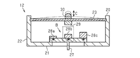
- FIG. 2 is an explanatory diagram of a stuffed toy as an electronic device according to the first embodiment.
- FIG. 2 is a cross-sectional view showing a state in which a first magnetic device having medium magnetism is positioned at a specific position in the beating device provided in the stuffed toy of FIG. 1.
- FIG. 3 is a cross-sectional view showing a state in which a first magnetic device having weak magnetism is located at a specific position in the beating apparatus of FIG.
- FIG. 3 is a cross-sectional view illustrating a state in which a first magnetic device having strong magnetism is located at a specific position in the beating device of FIG. 2.
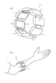
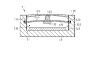
- FIG. 6 is a sectional view of a subunit of the haptic device of FIG.
- FIG. 4 is an explanatory diagram of the operation of the subunit.
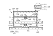
- FIG. 13 is an exemplary sectional view of a push-button switch as an electronic device according to a third embodiment;
- FIG. 4 is an explanatory diagram of an operation of a switch. Explanatory drawing of the beating apparatus which concerns on the example of a change of 1st Embodiment. Explanatory drawing of the beating apparatus which concerns on the example of a change of 1st Embodiment.
- FIG. 13 is a sectional view of a subunit according to a modification of the second embodiment. Explanatory drawing of the distribution part which concerns on the example of a change of 2nd Embodiment.
- FIG. 14 is an explanatory diagram of a switch according to a modification of the third embodiment.
- FIG. 14 is an explanatory diagram of a switch according to a modification of the third embodiment.
- the stuffed animal 10 has a skin material 11.
- the skin material 11 has a shape imitating an animal or the like, and is made of a soft material such as a cloth material.
- a beating device 12 is housed inside the skin material 11 together with a padding (not shown) such as cotton.
- the beating device 12 includes a base material 20 made of a hard resin such as PP and ABS.
- the base material 20 is a box-shaped member having a plate-shaped bottom wall 21, a peripheral wall 22 erected from the periphery of the bottom wall 21, and an opening defined by the peripheral wall 22.
- a dielectric elastomer actuator (DEA: Dielectric Elastomer Actuator) 23 is attached to the peripheral wall 22 of the base member 20. More specifically, the DEA 23 is attached near the distal end of the peripheral wall 22.
- the DEA 23 is supported by the peripheral wall 22 on the entire periphery thereof, and is disposed in the base material 20 in a state substantially parallel to the bottom wall 21.
- the DEA 23 includes a sheet-shaped dielectric portion 24 made of a dielectric elastomer, and a positive electrode 25 and a negative electrode 26 made of a conductive elastomer and laminated on both sides in the thickness direction of the dielectric portion 24. And a multilayer structure having: In the DEA 23, when a DC voltage is applied between the positive electrode 25 and the negative electrode 26, the dielectric part 24 is compressed in the thickness direction and along the surface of the dielectric part 24 according to the magnitude of the applied voltage. And deform to stretch in the surface direction.
- the dielectric elastomer constituting the dielectric part 24 is not particularly limited, and a known dielectric elastomer used for DEA can be used.
- the dielectric elastomer include a crosslinked polyrotaxane, silicone elastomer, acrylic elastomer, and urethane elastomer.
- One of these dielectric elastomers may be used, or a plurality of them may be used in combination.
- the thickness of the dielectric part 24 is, for example, 20 to 200 ⁇ m.
- the conductive elastomer forming the positive electrode 25 and the negative electrode 26 is not particularly limited, and a conductive elastomer used for a known DEA can be used.
- Examples of the conductive elastomer include a conductive elastomer containing an insulating polymer and a conductive filler.
- Examples of the insulating polymer include cross-linked polyrotaxane, silicone elastomer, acrylic elastomer, and urethane elastomer. One of these insulating polymers may be used, or a plurality of them may be used in combination.
- Examples of the conductive filler include Ketjen Black (registered trademark), carbon black, and metal particles. Examples of the metal particles include copper and silver. One of these conductive fillers may be used, or a plurality of them may be used in combination.
- the thickness of the positive electrode 25 and the negative electrode 26 is, for example, 10 to 100 ⁇ m.
- a movable member 27 that can slide linearly along the inner surface of the bottom wall 21 is attached.
- the movable member 27 includes a main body 27a and an operation lever 27b.
- the main body 27 a is provided so as to be slidable on the inner surface of the bottom wall 21 of the base material 20.
- the operation lever 27b protrudes outside the base member 20 from the main body 27a.
- the bottom wall 21 of the base material 20 is provided with an insertion hole 21a through which the operation lever 27b is inserted.
- a plurality of first magnetic devices are attached to the upper surface of the main body 27a by screws. That is, the plurality of first magnetic devices are attached to the bottom wall 21 of the base member 20 via the movable member 27. These plurality of first magnetic devices are constituted by columnar magnets, and have mutually different magnetism. Although the number of the first magnetic devices is not particularly limited, in the first embodiment, as an example, three first magnetic devices 28a to 28c are provided.
- the first magnetic device 28a is a magnet having relatively weak magnetism.
- the first magnetic device 28b is a magnet having medium magnetism.
- the first magnetic device 28c is a magnet having relatively strong magnetism.
- the first magnetic devices 28a to 28c are juxtaposed along the moving direction A so that the magnetism increases in order toward one side in the moving direction A of the movable member 27.
- a second magnetic device 29 is attached to the center of the first main surface 23a of the DEA 23 (the surface facing the bottom wall 21 of the base material 20).
- the second magnetic device 29 is configured by a disk-shaped magnet.
- the second magnetic device 29 is configured to generate a repulsive force between the second magnetic device 29 and the first magnetic devices 28a to 28c. Therefore, the central portion of the DEA 23 to which the second magnetic device 29 is attached is separated from the first magnetic devices 28a to 28c by a repulsive force generated between the first magnetic devices 28a to 28c and the second magnetic device 29.
- the urging force is always acting.
- the pad 30 is attached to the center of the second main surface 23b, which is the surface of the DEA 23 opposite to the first main surface 23a. That is, in the DEA 23, the pad 30 is attached to a portion opposite to the portion where the second magnetic device 29 is attached. When no voltage is applied to the DEA 23, the tip of the pad 30 is close to or in contact with the skin material 11.
- a control unit 32 and a power supply 33 are attached to the outer surface of the peripheral wall 22 of the base material 20.
- the control unit 32 and the power supply 33 are electrically connected to the DEA 23 via the conductor 31.
- the control unit 32 controls the voltage applied from the power supply 33 to the DEA 23 to increase or decrease in a predetermined cycle.
- the movable member 27 of the beating device 12 is operated to set one of the first magnetic devices 28a to 28c at the specific position B which is a position facing the second magnetic device 29.
- the movable member 27 is displaced so that the first magnetic device 28 b having medium magnetism is located at the specific position B.
- the DEA 23 expands and contracts in the plane direction.
- the DEA 23 is continuously deformed so that the repulsive force (the urging force acting on the DEA 23) between the first magnetic device 28b and the second magnetic device 29 located at the specific position B and the tension of the DEA 23 are balanced. I do.
- the central portion of the DEA 23 is continuously displaced in the up-down direction (the direction approaching and separating from the first magnetic device 28b).
- the DEA 23 vibrates up and down at a predetermined rhythm simulating a heartbeat.
- the vibration of the DEA 23 is transmitted to the skin material 11 through the pad 30.
- the user can visually and tactilely feel the beating of the stuffed animal 10.
- the beating device 12 can adjust the output (the size of the beating) based on the displacement width C of the DEA 23 by operating the movable member 27.
- the movable member 27 is displaced to the right, and the first magnetic device 28a having weak magnetism is positioned at the specific position B.
- the displacement width C of the DEA 23 is small. As a result, the beating of the stuffed animal 10 becomes smaller.
- the movable member 27 is displaced to the left to position the first magnetic device 28c having strong magnetism at the specific position B.
- the displacement width C of the DEA 23 increases.
- the beating of the stuffed toy 10 increases.
- the stuffed toy 10 is a film-shaped DEA 23, a substrate 20 supporting the DEA 23, first magnetic devices 28a to 28c attached to the substrate 20, and first magnetic devices 28a to 28c attached to the DEA 23. And a second magnetic device 29 that generates a repulsive force between the second magnetic device 29 and the second magnetic device 29.
- the first magnetic devices 28a to 28c are configured to be movable.
- the first magnetic devices 28a to 28c are moved to change the repulsion (biasing force on the DEA 23) generated between the first magnetic devices 28a to 28c and the second magnetic device 29,
- the output of the DEA 23 can be adjusted.
- a repulsive force generated between the magnetic devices attached to the DEA 23 and the base member 20, respectively, is used.
- a space is formed between the first magnetic devices 28a to 28c and the second magnetic device 29.
- a space is formed between the first magnetic devices 28a to 28c and the DEA 23.
- the stuffed animal 10 includes a movable member 27 that can move relative to the base material 20.
- the first magnetic devices 28a to 28c are attached to the movable member 27. According to the above configuration, by displacing the movable member 27, the first magnetic devices 28a to 28c can be easily moved to arbitrary positions.
- a plurality of first magnetic devices 28a to 28c having different magnetisms are attached to the movable member 27.
- the stuffed toy 10 is configured so that the first magnetic device located at the specific position B can be changed by displacing the movable member 27.
- the second magnetic device 29 is configured to generate a repulsive force with the first magnetic devices 28a to 28c. According to the above configuration, the operation of the DEA 23 can be efficiently converted to the operation of the skin material 11.
- the wristband-type haptic device 110 is used by being worn on a user's arm.
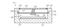
- the haptic device 110 includes a plurality of subunits 111 that present a pseudo force sense (tactile sensation) to a user, and a connection unit 112 that connects the plurality of subunits 111 in a ring shape.
- the configuration of each subunit 111 is the same.
- each subunit 111 includes a base material 120 made of a hard resin such as PP or ABS.
- the base material 120 is a rectangular box-shaped member having a rectangular plate-shaped bottom wall 121, a peripheral wall 122 erected from the periphery of the bottom wall 121, and an opening defined by the peripheral wall 122. Further, an action section 123 made of a soft material such as a cloth material is provided so as to close the opening of the base material 120.
- a film-like dielectric elastomer actuator (DEA: Dielectric Elastomer Actuator) 125 is attached to the center of the peripheral wall 122 of the base material 120 in the standing direction.
- the DEA 125 is housed inside the bag 124.
- the DEA 125 is supported on the peripheral wall 122 together with the bag body 124 along the entire periphery of the DEA 125, and is disposed in the base material 120 in a state substantially parallel to the bottom wall 121.
- the DEA 125 includes a sheet-shaped dielectric portion 126 made of a dielectric elastomer, and a positive electrode 127 and a negative electrode 128 made of a conductive elastomer and stacked on both sides of the dielectric portion 126 in the thickness direction. And a multilayer structure having: In the DEA 125, when a DC voltage is applied between the positive electrode 127 and the negative electrode 128, the dielectric part 126 is compressed in the thickness direction and along the surface of the dielectric part 126 according to the magnitude of the applied voltage. And deform to stretch in the surface direction.
- the dielectric elastomer constituting the dielectric portion 126 is not particularly limited, and a known dielectric elastomer used for DEA can be used.
- the dielectric elastomer include a crosslinked polyrotaxane, silicone elastomer, acrylic elastomer, and urethane elastomer.
- One of these dielectric elastomers may be used, or a plurality of them may be used in combination.
- the thickness of the dielectric part 126 is, for example, 20 to 200 ⁇ m.
- the conductive elastomer forming the positive electrode 127 and the negative electrode 128 is not particularly limited, and a known conductive elastomer used for DEA can be used.
- Examples of the conductive elastomer include a conductive elastomer containing an insulating polymer and a conductive filler.
- Examples of the insulating polymer include cross-linked polyrotaxane, silicone elastomer, acrylic elastomer, and urethane elastomer. One of these insulating polymers may be used, or a plurality of them may be used in combination.
- Examples of the conductive filler include Ketjen Black (registered trademark), carbon black, and metal particles. Examples of the metal particles include copper and silver. One of these conductive fillers may be used, or a plurality of them may be used in combination.
- the thickness of the positive electrode 127 and the negative electrode 128 is, for example, 10 to 100 ⁇ m.
- the DEA 125 is provided with a contact 129 for applying a voltage to the positive electrode 127 and the negative electrode 128.
- the contact 129 is provided so that a part thereof is exposed from the bag body 124.
- the contact 129 is connected to a conducting wire (not shown) at the exposed portion.
- the bag 124 is made of a soft material such as PP, PE, or PVC.
- An insulating oil 130 is sealed in a liquid-tight manner inside the bag body 124.
- the DEA 125 is arranged in contact with the insulating oil 130 inside the bag body 124.
- Examples of the insulating oil 130 include vegetable oil and insulating oil specified in JIS C2320. Vegetable oils include, for example, castor oil.
- examples of the insulating oil specified in JIS C2320 include mineral oil, alkylbenzene, polybutene, alkylnaphthalene, and alkyldiphenylalkane.
- first magnetic device 131 is attached to the inner surface of the bottom wall 121 of the base material 120.
- the first magnetic device 131 is configured by a plate-like magnet.
- a second magnetic device 132 is attached to the center of the first main surface 125a (the surface facing the bottom wall 121 side of the base material 120) of the DEA 125.
- the second magnetic device 132 is constituted by a disk-shaped magnet.
- the second magnetic device 132 is arranged inside the bag 124 together with the DEA 125.
- the second magnetic device 132 is configured to generate a repulsive force between the second magnetic device 132 and the first magnetic device 131. Therefore, the repulsive force generated between the first magnetic device 131 and the second magnetic device 132 causes the central portion of the DEA 125 to which the second magnetic device 132 is attached to be biased in a direction away from the first magnetic device 131. Is always working.
- a pad 133 as a transmission unit is attached to the center of the second main surface 125b, which is the surface of the DEA 125 opposite to the first main surface 125a. That is, in the DEA 125, a pad 133 as a transmission unit is attached to a portion opposite to the portion where the second magnetic device 132 is attached.
- the pad 133 is arranged inside the bag 124 together with the DEA 125. In a state where no voltage is applied to the DEA 125, the tip of the pad 133 is in proximity to or in contact with the action section 123 via the bag 124.
- the plurality of subunits 111 are annularly formed by the connecting unit 112 in a state where each subunit 111 faces the action unit 123 inward. Are linked.
- the haptic device 110 is mounted on the user such that the action section 123 of the subunit 111 is in contact with the user's arm.
- the DEA 125 expands in the plane direction.
- the repulsive force generated between the first magnetic device 131 and the second magnetic device 132 causes the DEA 125 to be displaced in a direction away from the first magnetic device 131, that is, toward the action portion 123.
- the DEA 125 is deformed so that the repulsive force (biasing force acting on the DEA 125) between the first magnetic device 131 and the second magnetic device 132 and the tension of the DEA 125 are balanced.
- the central portion of the DEA 125 swells toward the action portion 123.
- the bag 124 accommodating the DEA 125 also deforms following the operation of the DEA 125.
- the stroke of the subunit 111 which can be defined as the amount of expansion of the action portion 123, is an amount corresponding to the amount of expansion of the DEA 125 in the surface direction that changes according to the applied voltage. Therefore, the stroke of the subunit 111 can be finely adjusted by controlling the applied voltage.
- the voltage When applying a voltage to the DEA 125, the voltage may be applied in a pulsed manner. In this case, the difference in hardness can be expressed by changing the interval (frequency) between the pulses.
- the haptic device 110 includes a film-like DEA 125, a base material 120 supporting the DEA 125, a first magnetic device 131 attached to the base material 120, and a first magnetic device 131 attached to the DEA 125. And a second magnetic device 132 that generates a repulsive force.
- DEA 125 is arranged in contact with insulating oil 130.
- the DEA 125 is disposed in contact with the insulating oil 130, adhesion of dust, moisture, and the like to the DEA 125 is suppressed. Thereby, the dielectric breakdown resistance of the DEA 125 is improved, and the life of the DEA 125 can be extended.
- a repulsive force generated between the magnetic devices attached to the DEA 125 and the base 120 is used instead of an elastic member such as a spring connecting the DEA and the base.
- an elastic member such as a spring connecting the DEA and the base.
- the DEA 125 and the second magnetic device 132 are disposed inside the bag 124 in which the insulating oil 130 is sealed.
- the bag 124 is configured to deform following the operation of the DEA 125.
- the second magnetic device 132 is configured to generate a repulsive force with the first magnetic device 131.
- the operation of the DEA 125 can be efficiently converted into a pseudo force sense (tactile sensation) presented to the user.
- the haptics device 110 includes an action unit 123 disposed on the second main surface 125b side of the DEA 125 so as to be separated from the DEA 125.
- a pad 133 for transmitting a force based on the operation of the DEA 125 to the action section 123 is provided on the second main surface 125b of the DEA 125.
- a space in which the insulating oil can be arranged is formed between the DEA 125 and the action section 123. Therefore, the insulating oil 130 can be easily arranged on the second main surface 125b side of the DEA 125.
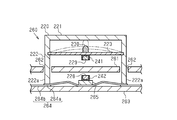
- the switch 260 includes a bottomed cylindrical button body 220 (first base), a plate-shaped mounting portion 263 (second base), and a plate-shaped base 261 (third base). ).
- the button body 220 is detachably attached to the base 261 from the front side of the base 261.
- the switch 260 is configured to open and close the electric circuit 264 in accordance with the pressing operation of the button main body 220 with respect to the base 261.
- the mounting portion 263 is disposed on the back side of the base 261 at a distance from the base 261 in the front and back direction of the base 261 (vertical direction in FIG. 8).
- the base 261, the mounting portion 263, and the button body 220 are made of a hard resin such as PP or ABS.
- the button body 220 is a cylindrical member having a plate-like top wall 221, a peripheral wall 222 erected from the periphery of the top wall 221, and an opening defined by the peripheral wall 222.
- a plurality of insertion portions 222a that are inserted into the plurality of insertion holes 262 formed in the base 261 are formed at the distal end of the peripheral wall 222.
- a first contact 264a for urging the button body 220 upward in FIG. 8 is attached to the upper surface of the attachment portion 263.
- the first contact 264a is a leaf spring made of metal.
- the center of the first contact point 264a is attached to the upper surface of the attachment portion 263.
- a second contact 264b is attached to a portion of the upper surface of the attachment portion 263 opposite to both ends of the first contact 264a.
- the insertion portions 222a of the button body 220 are detachably attached to both ends of the first contact 264a.
- a fitting portion made of a hard resin is fixed on the upper surface of the first contact 264a, and the fitting There is a mode such as providing a fitted portion fitted to the mating portion.
- Both ends of the first contact 264a are separated from the second contact 264b when no external force based on the pushing operation by the user is applied.
- the button body 220 is attached to the base 261 in a state in which the button body 220 is slidable in the vertical direction (push direction) in FIG.
- DEDEA 223 is attached near the base end of the peripheral wall 222 of the button body 220. The entire periphery of the DEA 223 is supported by the peripheral wall 222. The DEA 223 is disposed inside the button body 220 in a state substantially parallel to the top wall 221 on the front side of the base 261.
- the DEA 223 includes a sheet-shaped dielectric portion 224 made of a dielectric elastomer and a positive electrode 225 and a negative electrode 226 made of a conductive elastomer and laminated on both sides of the dielectric portion 224 in the thickness direction. And a multilayer structure having: In the DEA 223, when a DC voltage is applied between the positive electrode 225 and the negative electrode 226, the dielectric part 224 is compressed in the thickness direction and along the surface of the dielectric part 224 according to the magnitude of the applied voltage. And deform to stretch in the surface direction.
- the dielectric elastomer constituting the dielectric portion 224 is not particularly limited, and a known dielectric elastomer used for DEA can be used.
- the dielectric elastomer include a crosslinked polyrotaxane, silicone elastomer, acrylic elastomer, and urethane elastomer.
- One of these dielectric elastomers may be used, or a plurality of them may be used in combination.
- the thickness of the dielectric part 224 is, for example, 20 to 200 ⁇ m.
- the conductive elastomer constituting the positive electrode 225 and the negative electrode 226 is not particularly limited, and a known conductive elastomer used for DEA can be used.
- Examples of the conductive elastomer include a conductive elastomer containing an insulating polymer and a conductive filler.
- Examples of the insulating polymer include cross-linked polyrotaxane, silicone elastomer, acrylic elastomer, and urethane elastomer. One of these insulating polymers may be used, or a plurality of them may be used in combination.
- Examples of the conductive filler include Ketjen Black (registered trademark), carbon black, and metal particles. Examples of the metal particles include copper and silver. One of these conductive fillers may be used, or a plurality of them may be used in combination.
- the thickness of the positive electrode 225 and the negative electrode 226 is, for example, 10 to 100 ⁇ m.
- first magnetic device 228 is attached to the center of the first contact point 264a via the second shielding member 242 and the fixing portion 265. That is, the first magnetic device 228 is attached to the attachment portion 263 (second base material) via the second shield member 242, the fixing portion 265, and the first contact 264a.
- the first magnetic device 228 is configured by a columnar magnet.
- the fixing portion 265 is formed of a hard resin.
- the second magnetic device 229 is attached to the center of the first main surface 223a (the surface facing the base 261 side) of the DEA 223 via the first shielding member 241.
- the second magnetic device 229 is configured by a columnar magnet.
- the second magnetic device 229 is configured to generate a repulsive force with the first magnetic device 228.
- the first shielding member 241 has a bottom wall 241a and a side wall 241b, and has a bottomed cylindrical shape.
- the bottom wall portion 241a covers the entire end surface 229a of the second magnetic device 229 on the side opposite to the first magnetic device 228 side.
- the side wall portion 241b is provided upright from the periphery of the bottom wall portion 241a, and covers the entire side surface 229b of the second magnetic device 229.
- the second shielding member 242 has a bottom wall 242a and a side wall 242b, and has a bottomed cylindrical shape.
- the bottom wall portion 242a covers the entire end surface 228a of the first magnetic device 228 on the side opposite to the second magnetic device 229 side.
- the side wall portion 242b is provided upright from the peripheral edge of the bottom wall portion 242a, and covers the entire side surface 228b of the first magnetic device 228.
- the first shielding member 241 and the second shielding member 242 are formed of a ferromagnetic material such as iron or nickel.
- a pad 230 is attached to the center of a second main surface 223b, which is a surface of the DEA 223 opposite to the first main surface 223a. That is, in the DEA 223, the pad 230 is attached to a portion opposite to the portion where the second magnetic device 229 is attached. When no voltage is applied to the DEA 223, the tip of the pad 230 is close to the top wall 221 of the button body 220.
- a contact (not shown) for applying a voltage to the positive electrode 225 and the negative electrode 226 is provided at a peripheral portion of the DEA 223.
- the contact is connected to a conductor (not shown).
- the first contact 264a is elastically deformed, so that the first contact 264a and the second contact 264b come into contact.
- the electric circuit 264 including the first contact 264a and the second contact 264b is switched from the off state to the on state.
- a voltage is applied to the DEA 223 so as to vibrate the DEA 223 up and down, and the pad 230 attached to the DEA 223 strikes the top wall 221 of the button body 220.
- the user can feel that the electric circuit 264 has been switched by feeling the vibration of the pad 230 hitting the button body 220.
- the switch 260 includes a button main body 220 (first base material), a film-shaped DEA 223 supported by the button main body 220, and a first magnetic device 228 mounted on the mounting portion 263 (second base material). , DEA 223 on the first magnetic device 228 side (first main surface 223 a), and a second magnetic device 229 that generates a repulsive force with the first magnetic device 228. Further, a first shielding member 241 made of a ferromagnetic material that covers the second magnetic device 229 is provided on the second magnetic device 229 on the side opposite to the first magnetic device 228 side.
- the second magnetic device 229 is attached to the surface of the DEA 223 on the first magnetic device 228 side (the first main surface 223a), the distance between the first magnetic device 228 and the second magnetic device 229 is increased. Repulsive force can be generated effectively.
- the light is generated from the end surface 229a of the second magnetic device 229.
- the magnetic flux penetrating the film surface of the DEA 223 can be reduced.
- generation of an eddy current on the film surface due to the magnetic flux can be suppressed. Therefore, power consumption can be reduced.
- a repulsive force generated between the magnetic devices attached to the DEA 223 and the attachment portion 263 is used.
- the DEA 223 can be replaced without interfering with the first magnetic device 228. it can.
- the first shielding member 241 covers the side surface 229b of the second magnetic device 229.
- the side surface 229 b is covered with the first shielding member 241. Therefore, of the magnetic flux generated from the side surface 229b of the second magnetic device 229, the magnetic flux penetrating through the film surface of the DEA 223 can be reduced. Thus, generation of an eddy current on the film surface due to the magnetic flux can be suppressed.
- a second shielding member 242 made of a ferromagnetic material that covers the first magnetic device 228 is provided.
- the light is generated from the end surface 228 a of the first magnetic device 228.
- the magnetic flux penetrating the film surface of the DEA 223 can be reduced.
- generation of an eddy current on the film surface due to the magnetic flux can be suppressed.
- a second shielding member 242 made of a ferromagnetic material and covering the first magnetic device 228 is provided around the side surface 228b of the first magnetic device 228. According to the above configuration, since the side surface 228b of the first magnetic device 228 is covered by the second shielding member 242, the magnetic flux penetrating through the film surface of the DEA 223 among the magnetic fluxes generated from the side surface 228b of the first magnetic device 228. Can be reduced. Thus, generation of an eddy current on the film surface due to the magnetic flux can be suppressed.
- the switch 260 includes a film-shaped DEA 223, a plate-shaped base 261, and a button body 220 that is detachably provided to the base 261 and supports the DEA 223 on the front side of the base 261.
- the switch 260 includes a first magnetic device 228 disposed on the back side of the base 261 and a second magnetic device 229 attached to the DEA 223 and generating a repulsive force between the first magnetic device 228 and the first magnetic device 228.
- the button body 220 that supports the DEA 223 is detachably provided to the base 261, the button body 220 can be removed without removing the first magnetic device 228 disposed on the back side of the base 261. Can be removed. As a result, the DEA 223 can be easily replaced.
- the second magnetic device 229 generates a repulsive force with the first magnetic device 228. According to the above configuration, the operation of the DEA 223 can be efficiently converted to a pseudo force sense (tactile sensation) presented to the user.
- the switch 260 is a push button type that opens and closes the electric circuit 264 in response to the pressing operation of the button body 220 into the base 261.
- the DEA 223 is provided with a pad 230 for transmitting a force based on the operation of the DEA 223 to the button body 220.
- the button body 220 that supports the DEA 223 is detachably provided to the base 261, the button body 220 can be removed without removing the first magnetic device 228 disposed on the back side of the base 261. Can be removed. Thus, the replacement of the button body 220 including the DEA 223 can be easily performed.
- first to third embodiments can be modified and implemented as follows.
- the first to third embodiments and modified examples can be implemented in combination with each other within a technically consistent range.
- the structure of the movable member 27 is not particularly limited as long as the first magnetic device located at the specific position B can be selected and changed from the plurality of first magnetic devices 28a to 28c having different magnetisms.
- the movable member 27 may be constituted by a turntable. In this case, it is preferable that a plurality of first magnetic devices 28a to 28c are arranged side by side around the center of rotation of the movable member 27.
- the movable member 27 may be displaced manually or may be displaced using a driving device such as a motor.
- the number of the first magnetic devices configured to be movable may be one. Also in this case, the positional relationship between the first magnetic device and the second magnetic device 29 changes due to the movement of the first magnetic device. Then, since the repulsion generated between the first magnetic device and the second magnetic device 29 changes due to the change in the positional relationship, the output of the DEA 23 can be adjusted.
- the direction in which the first magnetic device is moved is not particularly limited.
- the first magnetic device 28 may be moved in a direction approaching or separating from the second magnetic device 29. That is, the movable member 27 may constitute an adjustment mechanism for adjusting the distance between the first magnetic device 28 and the second magnetic device 29. Further, as shown in FIG. 11, the first magnetic device 28 may be moved so as to change the direction with respect to the second magnetic device 29. In this case, the direction of displacement of the DEA 23 changes.
- the adjustment of the output of the DEA 23 includes the adjustment of the displacement direction of the DEA 23.
- the repulsive force generated between the first magnetic device and the second magnetic device 29 is changed by replacing the first magnetic device with another device having different magnetism instead of moving the first magnetic devices 28a to 28c.
- the output of the DEA 23 may be adjusted by changing the output.
- an attachment portion 21 b (for example, a screw hole) for detachably attaching the first magnetic device is provided on the bottom wall 21 of the base material 20. Then, the first magnetic device attached to the attachment portion 21b is configured to be replaceable by selecting from a plurality of first magnetic devices 28a to 28c having different magnetisms.
- the position of the mounting portion 21b is preferably a portion of the base material 20 opposite to the side facing the DEA 23. In this case, when replacing the first magnetic device attached to the attachment portion 21b, the DEA 23 is unlikely to become an obstacle, and the replacement operation of the first magnetic device can be easily performed.
- the second magnetic device 29 may be configured to generate an attractive force between the first magnetic device 28a and the first magnetic device 28c.
- the DEA 23 and the skin material 11 be integrally operated by, for example, bonding the pad 30 and the skin material 11 which is an operation portion to which the operation of the DEA 23 is transmitted.
- magnets are used as the first magnetic devices 28a to 28c and the second magnetic device 29.
- the first magnetic devices 28a to 28c and the second magnetic device 29 are not limited to magnets.
- one of the first magnetic devices 28a to 28c and the second magnetic device 29 may be a magnet, and the other may be a magnetic material that generates an attractive force between itself and the magnet.
- the method of attaching the first magnetic devices 28a to 28c and the second magnetic device 29 may be changed.
- Examples of the attachment method include an attachment method using an adhesive and an attachment method using a magnetic force.
- the beating stuffed animal 10 in the first embodiment can be changed to a beating stuffed animal 310 shown in FIG.
- the same elements as those described in the first embodiment are denoted by the same reference numerals, and redundant description will be omitted.
- a beating device 312 having the base material 20 is housed inside the skin material 11.
- a movable member 327 slidable in a direction (up and down direction) approaching and separating from the DEA 23 is attached.
- the movable member 327 includes a main body 327a disposed inside the base 20 and an operation lever 327b protruding from the main body 327a to the outside of the base 20.
- the first magnetic device 328 is detachably attached to the upper surface of the main body 327a by screwing.
- the first magnetic device 328 is configured by a columnar magnet.
- a control unit 332 and a power supply 333 are mounted inside a corner of the base material 20 between the bottom wall 21 and the peripheral wall 22.
- the control unit 332 and the power supply 333 have the same functions as the control unit 32 and the power supply 33 of the first embodiment, and are electrically connected to the DEA 23 via the wiring 331a.
- the stuffed toy 310 includes an LED 334.
- the LED 334 is disposed in a portion of the stuffed toy 310 corresponding to the eyes of an animal or the like, and is electrically connected to the control unit 332 by a wiring 331b.
- the wires 331a and 331b are routed so that a part thereof passes through the space S between the first magnetic device 328 and the second magnetic device 29.
- the beating device 312 changes the distance between the first magnetic device 328 and the second magnetic device 29 by operating the movable member 327, and outputs an output based on the displacement width of the DEA 23 (the size of the beating). ) Can be adjusted. That is, the movable member 327 constitutes an adjustment mechanism for adjusting the distance between the first magnetic device 328 and the second magnetic device 29, similarly to the movable member 27 in the modification of FIG.
- the movable member 327 is displaced downward to increase the distance between the first magnetic device 328 and the second magnetic device 29, the distance between the first magnetic device 328 and the second magnetic device 29 is generated. Since the repulsive force is reduced, the displacement width of the DEA 23 is reduced. As a result, the beating of the stuffed animal 310 is reduced.
- the space S described above is used as a housing for disposing the wiring 331a of the DEA 23 and the wiring 331b of the LED 334. Further, a movable member 327 for adjusting the distance between the first magnetic device 328 and the second magnetic device 29 is provided, and the movement of the first magnetic device 328 in a direction approaching or moving away from the second magnetic device 329 is allowed.
- the above-mentioned space S is used as a space for causing this to occur.
- the wiring 331a of the DEA 23 and the wiring 331b of the LED 334 are arranged between the first magnetic device 328 and the second magnetic device 29.
- the wirings 331a and 331b are arranged between the DEA 23 and the base 20, so that the size of the device can be reduced. Further, it is easy to dispose the control unit 332 and the power supply 333 between the DEA 23 and the base material 20, so that the size of the apparatus can be further reduced.
- the stuffed toy 310 includes an adjustment mechanism (a movable member 327) for adjusting the distance between the first magnetic device 328 and the second magnetic device 29.
- an adjustment mechanism a movable member 327) for adjusting the distance between the first magnetic device 328 and the second magnetic device 29.
- the output of the DEA 23 can be adjusted by changing the repulsive force (biasing force on the DEA 23) generated between the first magnetic device 328 and the second magnetic device 29.
- the first magnetic device 328 is detachably attached to the base material 20. According to the above configuration, the output of the DEA 23 can be changed by replacing the urging means for urging the DEA 23. Then, the work space required for making the change can be reduced, and the size of the apparatus can be reduced.
- the adjustment mechanism for adjusting the distance between the first magnetic device 328 and the second magnetic device 29 is not limited to the movable member 327, and the adjustment mechanism between the first magnetic device 328 and the second magnetic device 29 Any device may be used as long as the first magnetic device 328 is moved relative to the second magnetic device 29 using the space S.
- the base member 20 includes a first portion to which the first magnetic device 328 is attached, and a second portion that supports the DEA 23 and is separate from the first portion. At least one of the first portion and the second portion may be configured to be movable so that the distance to the magnetic device 29 changes.
- the components arranged between the first magnetic device 328 and the second magnetic device 29 are not limited to various wirings such as the wiring 331a of the DEA 23 and the wiring 331b of the LED 334.
- the first magnetic device is attached to a portion of the bottom wall 21 of the base material 20 opposite to the side facing the DEA 23.
- the base member 20 is a component part of which (the bottom wall 21) is disposed between the first magnetic device and the second magnetic device 29.
- a bag 335 that wraps the DEA 23 is provided, and the DEA 23 and the second magnetic device 29 are arranged inside the bag 335.
- the bag 335 is a component part of which is disposed between the first magnetic device 328 and the second magnetic device 29.
- the insulating oil 130 may be sealed in the bag body 335 in a liquid-tight manner.
- the beating device 12 of the first embodiment can be changed to a beating device 412 shown in FIG.
- the beating device 412 corresponds to a modification in which the first shielding member 241 and the second shielding member 242 of the third embodiment are applied to a beating device.
- the same components as those described in the first embodiment and the third embodiment are denoted by the same reference numerals, and redundant description will be omitted.
- the beating device 412 includes the base 420.
- the base material 420 is a box-shaped member having a plate-shaped bottom wall 421, a peripheral wall 422 erected from the periphery of the bottom wall 421, and an opening defined by the peripheral wall 422.
- the bottom wall 421 is not provided with a hole corresponding to the insertion hole 21a.
- the first magnetic device 228 is attached to the bottom wall 421 via the second shielding member 242.
- a second magnetic device 229 is attached to the center of the first main surface 23 a of the DEA 23 via a first shielding member 241.
- the lines of magnetic force are indicated by broken lines.
- the use of the electronic device according to the first embodiment is not limited to the beating stuffed animal, but can be applied to all electronic devices including the film-shaped DEA.
- the configuration such as the shape of the substrate and the DEA may be changed according to the use of the electronic device.
- the support structure of the substrate supporting the DEA is not particularly limited, and a support structure used for a known electronic device having a film-like DEA can be applied.
- the entire periphery of the peripheral portion of the DEA 23 is supported by the base material 20, but a configuration in which a part of the peripheral portion of the DEA 23 is partially supported by the base material 20 may be employed. .
- the entire DEA 125 is arranged in the insulating oil 130, but it is sufficient if at least a part of the DEA 125 is in contact with the insulating oil 130.
- the central portion in the direction along the surface of the DEA 125 may be in contact with the insulating oil 130, or only one of the first main surface 125a and the second main surface 125b of the DEA 125 may be in contact with the insulating oil 130. It may be in a state of contact.
- the structure for disposing the DEA 125 in contact with the insulating oil 130 is not limited to the structure using the bag 124.
- a liquid-tight space defined by the base material 120 and the action part 123 is provided by providing a seal member 134 at a connection part between the base material 120 and the action part 123. Then, the DEA 125 may be brought into contact with the insulating oil 130 by filling the space with the insulating oil 130.
- the laminated structure of the ⁇ DEA 125 is not limited to the laminated structure of the second embodiment.
- a stacked structure having an insulating layer in the outermost layer may be used, or a stacked structure in which a plurality of positive electrodes 127 and a plurality of negative electrodes 128 are alternately stacked with a dielectric portion 126 interposed therebetween. Is also good.
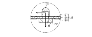
- a flow section for flowing the insulating oil 130 between the first main surface 125a side and the second main surface 125b side of the DEA 125 may be provided.
- a flow unit 135 penetrating the DEA 125, the second magnetic device 132, and the pad 133 is provided.
- the circulation part 135 By providing the circulation part 135, it is possible to suppress an increase in the oil pressure on the first main surface 125a side or the second main surface 125b side of the DEA 125 with the operation of the DEA 125.
- the circulation unit 135 is provided at a part of the DEA 125 where the second magnetic device 132 is attached, that is, at a part that becomes the center of operation or in the vicinity thereof. In this case, the effect on the operation of the DEA 125 due to the provision of the hole as the circulation unit 135 can be reduced.
- the second magnetic device 132 may be configured to generate an attractive force between the second magnetic device 132 and the first magnetic device 131.
- magnets are used as the first magnetic device 131 and the second magnetic device 132, but the first magnetic device 131 and the second magnetic device 132 are not limited to magnets.
- one of the first magnetic device 131 and the second magnetic device 132 may be a magnet, and the other may be a magnetic material that generates an attractive force between itself and the magnet.
- the method of attaching the first magnetic device 131 and the second magnetic device 132 may be changed.
- Examples of the attachment method include an attachment method using an adhesive and an attachment method using a magnetic force.
- the pad 133 is attached to the second main surface 125b of the DEA 125, but the pad 133 may be attached to the action section 123. Further, a projecting portion may be formed integrally with the action portion 123, and the projecting portion may constitute a transmitting portion.
- the first magnetic device 131 may be attached to the bottom wall 121 via a member corresponding to the second shielding member of the third embodiment.
- the second magnetic device 132 may be attached to the DEA 125 via a member corresponding to the first shielding member of the third embodiment.
- the application of the electronic device according to the second embodiment is not limited to the haptic device, but can be applied to all electronic devices including the film-shaped DEA. Further, the configuration such as the shape of the base material and the DEA may be changed according to the use of the electronic device. Further, the support structure of the substrate supporting the DEA is not particularly limited, and a support structure used for a known electronic device having a film-like DEA can be applied. For example, in the second embodiment, the entire periphery of the peripheral portion of the DEA 125 is supported by the base material 120, but a configuration in which a part of the peripheral portion of the DEA 125 is partially supported by the base material 120 may be employed. .
- the action section may be made of a hard material according to the use of the electronic device. For example, when transmitting vibration to a user, an action portion made of a hard material is suitable.
- the first shielding member 241 may cover a part of the end surface 229a of the second magnetic device 229. Further, the first shielding member 241 may cover a part of the side surface 229b of the second magnetic device 229.
- the first shielding member 241 may cover only the side surface 229b of the second magnetic device 229. That is, in the first shielding member 241, the bottom wall portion 241a may be omitted.
- the first shielding member 241 may cover only the end surface 229a of the second magnetic device 229. That is, in the first shielding member 241, the side wall portion 241b may be omitted.
- the second shield member 242 may cover a part of the end surface 228a of the first magnetic device 228. Further, the second shielding member 242 may cover a part of the side surface 228b of the first magnetic device 228.
- the second shielding member 242 may cover only the side surface 228b of the first magnetic device 228. That is, in the second shielding member 242, the bottom wall portion 242a may be omitted. -The second shielding member 242 may cover only the end surface 228a of the first magnetic device 228. That is, in the second shielding member 242, the side wall portion 242b may be omitted.
- -The 2nd shielding member 242 may be omitted.
- -The second magnetic device 229 may be configured to generate an attractive force with the first magnetic device 228.
- the pad 230 and the button main body 220 are bonded to each other so that the DEA 223 and the button main body 220 operate integrally.
- magnets are used as the first magnetic device 228 and the second magnetic device 229, but the first magnetic device 228 and the second magnetic device 229 are not limited to magnets.
- one of the first magnetic device 228 and the second magnetic device 229 may be a magnet, and the other may be a magnetic material that generates an attractive force with the magnet.
- the method of attaching the first magnetic device 228 and the second magnetic device 229 may be changed.
- Examples of the attachment method include an attachment method using an adhesive and an attachment method using a magnetic force.
- the second magnetic device 229 can be attached to the second main surface 223b of the DEA 223.
- the positive electrode 225 and the negative electrode 226 of the portion of the DEA 223 to which the second magnetic device 229 is attached may be omitted. In this case, generation of an eddy current on the film surface of the DEA 223 due to magnetic flux penetrating the film surface of the DEA 223 among the magnetic fluxes generated from the second magnetic device 229 can be suppressed, and power consumption can be reduced.
- the switch 260 in the third embodiment can be changed to a switch 540 shown in FIG.
- the switch 540 includes a button body 542 (first base material) having a bottomed cylindrical shape, and a plate-shaped base 541 (second base material).
- the button body 542 is attached to the front side of the base 541.
- the button main body 542 is attached to the base 541 so as to be slidable in the up-down direction (push-in direction) and locked.
- the button body 542 includes a protrusion 542a that protrudes from the inner peripheral surface of the peripheral wall.
- An urging member 543 for urging the button body 542 upward is provided between the protrusion 542a and the base 541.
- the DEA 523 is attached inside the button body 542 in a manner supported by the peripheral wall of the button body 542.
- the DEA 523 has the same configuration as the DEA 223 in the third embodiment.
- the second magnetic device 529 is attached to the center of the first main surface (the surface facing the base 541) of the DEA 523.
- the second magnetic device 529 is configured by a magnet.
- a pad 530 is attached to the center of the second main surface of the DEA 523 opposite to the first main surface.
- the first magnetic device 528 is attached to the back surface (the surface opposite to the DEA 523) of the base 541.
- the first magnetic device 528 is configured by a magnet.
- a first contact 544a and a second contact 544b are provided at opposing portions of the second magnetic device 529 and the base 541.
- the first contact 544a and the second contact 544b come into contact, and the electric circuit (not shown) is switched from the off state to the on state.
- a voltage is applied to the DEA 523 so as to vibrate the DEA 523 up and down, and the pad 530 attached to the DEA 523 hits the button body 542.
- the user can intuitively grasp that the electric circuit has been switched.
- the first contact 544a, the second contact 544b, and the base 541 (second base), which are components of the switch 540 are disposed between the first magnetic device 528 and the second magnetic device 529. I have.
- the switch 260 in the third embodiment can be changed to a switch 640 shown in FIG.
- the switch 640 includes a bottomed cylindrical button body 642 (first base) and a plate-like base 641 (second base).
- the button body 642 is attached to the front side of the base 641.
- the button main body 642 is attached to the base 641 so as to be slidable in the vertical direction (push-in direction) and to be prevented from falling off.
- the button body 642 has a protruding portion 642a that protrudes from the inner peripheral surface of the peripheral wall.
- An urging member 643 that urges the button body 642 upward is provided between the protrusion 642a and the base 641.
- a first contact 644a and a second contact 644b are provided at opposing portions of the protrusion 642a and the base 641.
- the DEA 623 is attached to the inside of the button body 642 so as to be supported on the peripheral wall of the button body 642.
- the DEA 623 has the same configuration as the DEA 223 of the third embodiment.
- a second magnetic device 629 is attached to the center of the main surface (first main surface) on the base 641 side of the DEA 623.
- the second magnetic device 629 is configured by a magnet.
- a pad 630 is attached to the center of the main surface (second main surface) of the DEA 623 opposite to the base 641 side.
- a movable member 627 that can slide linearly along the back surface of the base 641 is attached to the back surface of the base 641.
- a plurality of first magnetic devices 628a to 628c having different magnetisms are attached to the movable member 627.
- the first contact 644a and the second contact 644b come into contact with each other, and the electric circuit (not shown) is switched from the off state to the on state.
- a voltage is applied to the DEA 623 so as to vibrate the DEA 623 up and down, and the pad 630 attached to the DEA 623 strikes the button body 642.
- the user can intuitively grasp that the electric circuit has been switched by feeling the vibration of the pad 630 hitting the button body 642.
- the movable member 627 is displaced to change the first magnetic device located at the specific position B facing the second magnetic device 629, the output of the DEA 623 changes, and the intensity of the vibration transmitted to the user from the switch 640 is changed. Can be adjusted.
- the use of the electronic device according to the third embodiment is not limited to a switch, but can be applied to all electronic devices including a film-like DEA. Further, the configuration such as the shape of the base material and the DEA may be changed according to the use of the electronic device. Further, the support structure of the substrate supporting the DEA is not particularly limited, and a support structure used for a known electronic device having a film-like DEA can be applied. For example, in the third embodiment, the entire periphery of the peripheral portion of the DEA 223 is supported by the button body 220, but a configuration in which a part of the peripheral portion of the DEA 223 is partially supported by the button body 220 may be employed. .
Landscapes
- Engineering & Computer Science (AREA)
- General Engineering & Computer Science (AREA)
- Theoretical Computer Science (AREA)
- Human Computer Interaction (AREA)
- Physics & Mathematics (AREA)
- General Physics & Mathematics (AREA)
- User Interface Of Digital Computer (AREA)
Abstract
ぬいぐるみ(10)は、膜状のDEA(23)と、DEA(23)を支持する基材(20)と、基材(20)に取り付けられた第1磁気デバイス(28)と、DEA(23)に取り付けられ、第1磁気デバイス(28)との間に斥力を発生させる第2磁気デバイス(29)とを備えている。
Description
本開示は、誘電エラストマーアクチュエータを備える電子機器に関する。
近年、誘電エラストマーアクチュエータを利用した電子機器の開発が行われている。例えば、特許文献1には、膜状の誘電エラストマーアクチュエータと、誘電エラストマーアクチュエータを支持する基材と、誘電エラストマーアクチュエータを弾性的に付勢する弾性部材とを備えたダイアフラムバルブが開示されている。開状態にあるダイアフラムバルブの誘電エラストマーアクチュエータに電圧が印加されると、誘電エラストマーアクチュエータは、面方向に伸張し、弾性部材の付勢力によりオリフィスを覆うように押し下げられる。これにより、ダイアフラムバルブは、開状態から閉状態に切り替わる。
本開示の目的は、誘電エラストマーアクチュエータを備える電子機器における設計の自由度を向上させることにある。
上記課題を解決する電子機器は、膜状の誘電エラストマーアクチュエータと、前記誘電エラストマーアクチュエータを支持する基材と、前記基材に取り付けられた第1磁気デバイスと、前記誘電エラストマーアクチュエータに取り付けられ、前記第1磁気デバイスとの間に斥力又は引力を発生させる第2磁気デバイスとを備える。
上記構成では、誘電エラストマーアクチュエータを付勢する付勢手段として、誘電エラストマーアクチュエータ及び基材のそれぞれに取り付けた磁気デバイス間に発生する斥力又は引力を用いている。これにより、第1磁気デバイスと第2磁気デバイスとが離間した状態となり、第1磁気デバイスと第2磁気デバイスとの間に空間が形成される。この空間を利用して、種々の配線を配索したり、可動部分を設けたりすることが可能であり、電子機器の設計の自由度が向上する。
上記電子機器において、前記第1磁気デバイスと前記第2磁気デバイスとの間には、当該電子機器を構成する構成部品の少なくとも一部が配置されていることが好ましい。前記構成部品は、前記基材、配線、スイッチの接点、及び前記誘電エラストマーアクチュエータを包む袋体のうちの少なくとも一つであることが好ましい。
上記構成によれば、装置の小型化や長寿命化を図ることができる。
上記電子機器において、前記第1磁気デバイスと前記第2磁気デバイスとの間の距離を調整する調整機構を備えることが好ましい。
上記電子機器において、前記第1磁気デバイスと前記第2磁気デバイスとの間の距離を調整する調整機構を備えることが好ましい。
上記構成によれば、第1磁気デバイスと第2磁気デバイスとの間に発生する斥力又は引力(誘電エラストマーアクチュエータに対する付勢力)を変化させることにより、誘電エラストマーアクチュエータの出力を調節できる。
上記電子機器において、前記第1磁気デバイスは、前記基材に対して取り外し可能に取り付けられていることが好ましい。
上記構成によれば、誘電エラストマーアクチュエータを付勢する付勢手段を取り替えて誘電エラストマーアクチュエータの出力を変更することができる。そして、その変更を行う際に必要となる作業スペースを小さくすることができ、装置を小型化できる。
上記構成によれば、誘電エラストマーアクチュエータを付勢する付勢手段を取り替えて誘電エラストマーアクチュエータの出力を変更することができる。そして、その変更を行う際に必要となる作業スペースを小さくすることができ、装置を小型化できる。
上記付勢手段として、ばね等の弾性部材を用いた場合には、弾性部材を取り替える際に、弾性部材の取り外し及び取り付け作業を誘電エラストマーアクチュエータ及び基材の両方に対して行う必要がある。そのため、誘電エラストマーアクチュエータに対する作業のためのスペースと、基材に対する作業のためのスペースとの両方を確保する必要がある。
これに対して、上記付勢手段として、第1磁気デバイス及び第2磁気デバイスを用いた場合には、第2磁気デバイスはそのままの状態として、基材に対して第1磁気デバイスの取り外し及び取り付け作業を行えばよい。そのため、第2磁気デバイスの取り外し及び取り付け作業に必要となる作業スペースを確保する必要がなく、作業スペースを小さくできる。
上記電子機器において、前記第2磁気デバイスは、前記第1磁気デバイスとの間に斥力を発生させることが好ましい。
上記構成によれば、誘電エラストマーアクチュエータの動作を、使用者に提示する疑似力覚(触感)に効率的に変換できる。
上記構成によれば、誘電エラストマーアクチュエータの動作を、使用者に提示する疑似力覚(触感)に効率的に変換できる。
上記電子機器は、前記第2磁気デバイスにおける前記第1磁気デバイス側とは反対側に設けられ、前記第2磁気デバイスを覆う強磁性体製の遮蔽部材をさらに備えることが好ましい。
消費電力を低減できる電子機器が求められている。この点、上記構成によれば、第2磁気デバイスにおける第1磁気デバイス側とは反対側の部位が遮蔽部材によって覆われているため、第2磁気デバイスの上記部位から発生する磁束のうち誘電エラストマーアクチュエータの膜面を貫通する磁束を低減することができる。これにより、当該磁束によって上記膜面に渦電流が発生することを抑制できる。したがって、消費電力を低減することができる。
上記電子機器において、前記遮蔽部材は、前記第2磁気デバイスの側面を覆っていることが好ましい。
上記構成によれば、第2磁気デバイスにおける第1磁気デバイス側とは反対側の部位に加えて、第2磁気デバイスの側面が遮蔽部材によって覆われているため、第2磁気デバイスの側面から発生する磁束のうち誘電エラストマーアクチュエータの膜面を貫通する磁束を低減することができる。これにより、当該磁束によって上記膜面に渦電流が発生することを抑制できる。
上記構成によれば、第2磁気デバイスにおける第1磁気デバイス側とは反対側の部位に加えて、第2磁気デバイスの側面が遮蔽部材によって覆われているため、第2磁気デバイスの側面から発生する磁束のうち誘電エラストマーアクチュエータの膜面を貫通する磁束を低減することができる。これにより、当該磁束によって上記膜面に渦電流が発生することを抑制できる。
上記電子機器は、前記第2磁気デバイスの側面の周囲に設けられ、前記第2磁気デバイスを覆う強磁性体製の遮蔽部材をさらに備えることが好ましい。
上記構成によれば、第2磁気デバイスの側面が遮蔽部材によって覆われているため、第2磁気デバイスの側面から発生する磁束のうち誘電エラストマーアクチュエータの膜面を貫通する磁束を低減することができる。これにより、当該磁束によって上記膜面に渦電流が発生することを抑制できる。
上記構成によれば、第2磁気デバイスの側面が遮蔽部材によって覆われているため、第2磁気デバイスの側面から発生する磁束のうち誘電エラストマーアクチュエータの膜面を貫通する磁束を低減することができる。これにより、当該磁束によって上記膜面に渦電流が発生することを抑制できる。
上記電子機器において、前記第2磁気デバイスは、前記誘電エラストマーアクチュエータにおける前記第1磁気デバイス側の面に取り付けられていることが好ましい。
上記構成によれば、第2磁気デバイスが誘電エラストマーアクチュエータにおける第1磁気デバイス側の面に取り付けられているため、第1磁気デバイスと第2磁気デバイスとの間に斥力又は引力を効果的に発生させることができる。
上記構成によれば、第2磁気デバイスが誘電エラストマーアクチュエータにおける第1磁気デバイス側の面に取り付けられているため、第1磁気デバイスと第2磁気デバイスとの間に斥力又は引力を効果的に発生させることができる。
上記電子機器において、前記遮蔽部材は第1遮蔽部材であり、上記電子機器は、前記第1磁気デバイスにおける前記第2磁気デバイス側とは反対側に設けられ、前記第1磁気デバイスを覆う強磁性体製の第2遮蔽部材をさらに備えることが好ましい。
上記構成によれば、第1磁気デバイスにおける第2磁気デバイス側とは反対側の部位が第2遮蔽部材によって覆われているため、第1磁気デバイスの上記部位から発生する磁束のうち誘電エラストマーアクチュエータの膜面を貫通する磁束を低減することができる。これにより、当該磁束によって上記膜面に渦電流が発生することを抑制できる。
上記電子機器において、前記遮蔽部材は第1遮蔽部材であり、上記電子機器は、前記第1磁気デバイスの側面の周囲に設けられ、前記第1磁気デバイスを覆う強磁性体製の第2遮蔽部材をさらに備えることが好ましい。
上記電子機器において、前記第2遮蔽部材は、前記第1磁気デバイスの側面の周囲に設けられ、前記第1磁気デバイスを覆う側壁部を備えることが好ましい。
上記構成によれば、第1磁気デバイスの側面が第2遮蔽部材によって覆われているため、第1磁気デバイスの側面から発生する磁束のうち誘電エラストマーアクチュエータの膜面を貫通する磁束を低減することができる。これにより、当該磁束によって上記膜面に渦電流が発生することを抑制できる。
上記構成によれば、第1磁気デバイスの側面が第2遮蔽部材によって覆われているため、第1磁気デバイスの側面から発生する磁束のうち誘電エラストマーアクチュエータの膜面を貫通する磁束を低減することができる。これにより、当該磁束によって上記膜面に渦電流が発生することを抑制できる。
上記電子機器において、前記第1磁気デバイスは、移動可能又は取り替え可能に構成されていることが好ましい。
誘電エラストマーアクチュエータの出力を調節できる電子機器が求められている。この点、上記構成によれば、第1磁気デバイスを移動させる又は磁性の異なるものに取り換えて、第1磁気デバイスと第2磁気デバイスとの間に発生する斥力又は引力(誘電エラストマーアクチュエータに対する付勢力)を変化させることにより、誘電エラストマーアクチュエータの出力を調節できる。
誘電エラストマーアクチュエータの出力を調節できる電子機器が求められている。この点、上記構成によれば、第1磁気デバイスを移動させる又は磁性の異なるものに取り換えて、第1磁気デバイスと第2磁気デバイスとの間に発生する斥力又は引力(誘電エラストマーアクチュエータに対する付勢力)を変化させることにより、誘電エラストマーアクチュエータの出力を調節できる。
上記電子機器は、前記基材に対して相対動可能な可動部材を備え、前記第1磁気デバイスは、前記可動部材に取り付けられていることが好ましい。
上記構成によれば、可動部材を変位させることにより、第1磁気デバイスを任意の位置に容易に移動させることができる。
上記構成によれば、可動部材を変位させることにより、第1磁気デバイスを任意の位置に容易に移動させることができる。
上記電子機器において、前記第1磁気デバイスは磁性の異なる複数の第1磁気デバイスのうちのひとつであり、当該複数の第1磁気デバイスが前記可動部材に取り付けられており、前記電子機器は、前記可動部材を変位させることにより、前記第2磁気デバイスの位置に基づく特定位置に位置する第1磁気デバイスを変更可能に構成されていることが好ましい。
上記構成によれば、第1磁気デバイスの数に応じた多様な誘電エラストマーアクチュエータの出力パターンを有する電子機器が得られる。そして、可動部材を変位させるという簡易な操作により、誘電エラストマーアクチュエータの出力パターンを切り替えることができる。
上記電子機器において、前記基材は、前記第1磁気デバイスを取り外し可能に取り付けるための取付部を備え、前記取付部は、前記基材における前記誘電エラストマーアクチュエータを向く側の反対側となる部分に設けられていることが好ましい。
上記構成によれば、取付部に取り付けられた第1磁気デバイスを取り替える際に、誘電エラストマーアクチュエータが障害物になり難く、第1磁気デバイスの取り替え作業を容易に行うことができる。
上記電子機器において、前記第2磁気デバイスは、前記第1磁気デバイスとの間に斥力を発生させることが好ましい。
上記構成によれば、誘電エラストマーアクチュエータの動作を、使用者に提示する疑似力覚(触感)に効率的に変換できる。
上記構成によれば、誘電エラストマーアクチュエータの動作を、使用者に提示する疑似力覚(触感)に効率的に変換できる。
上記電子機器は板状の基部をさらに備え、前記基材は前記基部の表側から前記基部に対して着脱可能に設けられており、前記誘電エラストマーアクチュエータは前記基部の前記表側において前記基材に支持されており、前記第1磁気デバイスは前記基部の裏側に配置されていることが好ましい。
誘電エラストマーアクチュエータの交換を容易に行うことのできる電子機器が求められている。この点、上記構成によれば、誘電エラストマーアクチュエータを支持する基材が基部に対して着脱可能に設けられているため、基部の裏側に配置された第1磁気デバイスを取り除くことなく、基材を取り外すことができる。これにより、誘電エラストマーアクチュエータの交換を容易に行うことができる。
上記電子機器において、前記第2磁気デバイスは、前記第1磁気デバイスとの間に斥力を発生させることが好ましい。
上記構成によれば、誘電エラストマーアクチュエータの動作を、使用者に提示する疑似力覚(触感)に効率的に変換できる。
上記構成によれば、誘電エラストマーアクチュエータの動作を、使用者に提示する疑似力覚(触感)に効率的に変換できる。
上記電子機器において、前記基材は、押しボタン型のスイッチのボタン本体であり、前記スイッチは、前記基部に対する前記ボタン本体の押し込み操作に伴って電気回路を開閉するものであり、前記誘電エラストマーアクチュエータには、前記誘電エラストマーアクチュエータの動作に基づく力を前記ボタン本体に伝達する伝達部が設けられていることが好ましい。
上記構成によれば、誘電エラストマーアクチュエータを支持するボタン本体が基部に対して着脱可能に設けられているため、基部の裏側に配置された第1磁気デバイスを取り除くことなく、ボタン本体を取り外すことができる。これにより、誘電エラストマーアクチュエータの交換を容易に行うことができる。
また、上記構成によれば、誘電エラストマーアクチュエータの動作に基づく力が伝達部を通じてボタン本体に伝達される。使用者は、伝達部からボタン本体に伝達される振動を感じることにより、電気回路が切り替わったことを感覚的に把握できる。
上記電子機器において、前記誘電エラストマーアクチュエータは、少なくとも一部が絶縁油に接した状態で配置されていることが好ましい。
誘電エラストマーアクチュエータの耐久性を向上できる電子機器が求められている。この点、上記構成によれば、誘電エラストマーアクチュエータが絶縁油に接した状態で配置されているため、誘電エラストマーアクチュエータに対する埃や水分等の付着が抑制される。これにより、誘電エラストマーアクチュエータの絶縁破壊耐性が向上し、誘電エラストマーアクチュエータの長寿命化を図ることができる。
誘電エラストマーアクチュエータの耐久性を向上できる電子機器が求められている。この点、上記構成によれば、誘電エラストマーアクチュエータが絶縁油に接した状態で配置されているため、誘電エラストマーアクチュエータに対する埃や水分等の付着が抑制される。これにより、誘電エラストマーアクチュエータの絶縁破壊耐性が向上し、誘電エラストマーアクチュエータの長寿命化を図ることができる。
上記電子機器において、前記誘電エラストマーアクチュエータの少なくとも一部及び前記第2磁気デバイスは、前記絶縁油が封入された袋体の内部に配置され、前記袋体は、前記誘電エラストマーアクチュエータの動作に追従して変形することが好ましい。
上記構成によれば、誘電エラストマーアクチュエータに絶縁油が接している状態を少量の絶縁油にて実現できる。また、必要のない部分に絶縁油が接することを抑制できる。
上記電子機器において、前記第2磁気デバイスは、前記第1磁気デバイスとの間に斥力を発生させることが好ましい。
上記電子機器において、前記第2磁気デバイスは、前記第1磁気デバイスとの間に斥力を発生させることが好ましい。
上記構成によれば、誘電エラストマーアクチュエータの動作を、使用者に提示する疑似力覚(触感)に効率的に変換できる。
上記電子機器は、前記誘電エラストマーアクチュエータの第1主面側と第2主面側との間で前記絶縁油を流通させる流通部を備えることが好ましい。
上記電子機器は、前記誘電エラストマーアクチュエータの第1主面側と第2主面側との間で前記絶縁油を流通させる流通部を備えることが好ましい。
上記構成によれば、誘電エラストマーアクチュエータの動作に伴って誘電エラストマーアクチュエータの第1主面側又は第2主面側の絶縁油の油圧が上昇することを抑制できる。これにより、絶縁油の局所的な油圧の上昇に起因して、誘電エラストマーアクチュエータの動作の応答性が低下することを抑制できる。
上記電子機器は、前記誘電エラストマーアクチュエータの第2主面側において、前記誘電エラストマーアクチュエータから離間して配置される作用部を備え、前記誘電エラストマーアクチュエータ及び前記作用部の少なくとも一方には、前記誘電エラストマーアクチュエータの動作に基づく力を前記作用部に伝達する伝達部が設けられていることが好ましい。
上記構成によれば、誘電エラストマーアクチュエータと作用部との間に絶縁油を配置可能な空間が形成される。そのため、誘電エラストマーアクチュエータの第2主面側に絶縁油を容易に配置できる。
本開示の電子機器によれば、設計の自由度を向上させることができる。
(第1実施形態)
以下、本開示の電子機器を、鼓動するぬいぐるみ10に適用した第1実施形態について説明する。
以下、本開示の電子機器を、鼓動するぬいぐるみ10に適用した第1実施形態について説明する。
図1に示すように、ぬいぐるみ10は、表皮材11を備えている。表皮材11は、動物等を模した形状を有し、布材等の軟質材料により構成されている。表皮材11の内部には、綿等の詰め物(図示略)と共に鼓動装置12が収容されている。
鼓動装置12は、PP、ABS等の硬質樹脂により構成される基材20を備えている。基材20は、板状の底壁21と、底壁21の周縁から立設された周壁22と、周壁22により画定された開口とを有する箱状の部材である。基材20の周壁22には、膜状の誘電エラストマーアクチュエータ(DEA:Dielectric Elastomer Actuator)23が取り付けられている。詳しくは、DEA23は、周壁22の先端部近傍に取り付けられている。DEA23は、その周縁部分の全周が周壁22に支持され、底壁21に対して略平行な状態で基材20内に配置されている。
図1に拡大して示すように、DEA23は、誘電エラストマーからなるシート状の誘電部24と、導電エラストマーからなり、誘電部24の厚さ方向の両側に積層された正極電極25及び負極電極26とを有する多層構造体である。DEA23では、正極電極25と負極電極26との間に直流電圧が印加されると、印加電圧の大きさに応じて、誘電部24が厚さ方向に圧縮されるとともに誘電部24の面に沿って面方向に伸張するように変形する。
誘電部24を構成する誘電エラストマーは特に限定されるものではなく、公知のDEAに用いられる誘電エラストマーを用いることができる。上記誘電エラストマーとしては、例えば、架橋されたポリロタキサン、シリコーンエラストマー、アクリルエラストマー、及びウレタンエラストマーが挙げられる。これら誘電エラストマーのうちの一種を用いてもよいし、複数種を併用してもよい。誘電部24の厚さは、例えば、20~200μmである。
正極電極25及び負極電極26を構成する導電エラストマーは特に限定されるものではなく、公知のDEAに用いられる導電エラストマーを用いることができる。上記導電エラストマーとしては、例えば、絶縁性高分子及び導電性フィラーを含有する導電エラストマーが挙げられる。
上記絶縁性高分子としては、例えば、架橋されたポリロタキサン、シリコーンエラストマー、アクリルエラストマー、及びウレタンエラストマーが挙げられる。これら絶縁性高分子のうちの一種を用いてもよいし、複数種を併用してもよい。上記導電性フィラーとしては、例えば、ケッチェンブラック(登録商標)、カーボンブラック、及び金属粒子が挙げられる。金属粒子としては銅や銀等が挙げられる。これら導電性フィラーのうちの一種を用いてもよいし、複数種を併用してもよい。正極電極25及び負極電極26の厚さは、例えば、10~100μmである。
基材20の底壁21の中央部には、底壁21の内面に沿って直線的にスライド移動可能な可動部材27が取り付けられている。可動部材27は、本体部27a及び操作レバー27bを備えている。本体部27aは、基材20の底壁21の内面上をスライド移動可能に設けられている。操作レバー27bは、本体部27aから基材20の外側に突出している。なお、基材20の底壁21には、操作レバー27bが挿通される挿通孔21aが設けられている。
本体部27aの上面には、複数の第1磁気デバイスがネジ止めにより取り付けられている。即ち、複数の第1磁気デバイスが、可動部材27を介して基材20の底壁21に取り付けられている。これら複数の第1磁気デバイスは、円柱状の磁石により構成されており、互いに異なる磁性を有している。第1磁気デバイスの数は特に限定されるものではないが、第1実施形態では、一例として、3個の第1磁気デバイス28a~28cが設けられている。
第1磁気デバイス28aは、相対的に磁性が弱い磁石である。第1磁気デバイス28bは、磁性が中程度である磁石である。第1磁気デバイス28cは、相対的に磁性が強い磁石である。第1磁気デバイス28a~28cは、可動部材27の移動方向Aの一方側に向かって順に磁性が強くなるように移動方向Aに沿って並設されている。
DEA23の第1主面23a(基材20の底壁21側を向く面)の中央部には、第2磁気デバイス29が取り付けられている。第2磁気デバイス29は円板状の磁石により構成されている。第2磁気デバイス29は、第1磁気デバイス28a~28cとの間に斥力を発生させるように構成されている。したがって、第2磁気デバイス29が取り付けられたDEA23の中央部は、第1磁気デバイス28a~28cと第2磁気デバイス29との間に発生する斥力によって、第1磁気デバイス28a~28cから離間する方向への付勢力が常に作用する状態になっている。
DEA23における第1主面23aの反対側の面である第2主面23bの中央部には、パッド30が取り付けられている。即ち、DEA23において、第2磁気デバイス29が取り付けられている部分の反対側の部分には、パッド30が取り付けられている。DEA23に対して電圧が印加されていない状態において、パッド30の先端は、表皮材11に近接又は接触している。
また、基材20の周壁22の外面には、制御部32及び電源33が取り付けられている。これら制御部32及び電源33は、導線31によってDEA23に電気的に接続されている。制御部32は、電源33からDEA23に印加される電圧を所定の周期で増減させるように制御する。
次に、第1実施形態の作用について説明する。
まず、鼓動装置12の可動部材27を操作して、第2磁気デバイス29に対向する位置である特定位置Bに第1磁気デバイス28a~28cのうちのいずれかを位置させた状態にする。例えば、図2に示すように、磁性が中程度である第1磁気デバイス28bが特定位置Bに位置するように可動部材27を変位させる。
まず、鼓動装置12の可動部材27を操作して、第2磁気デバイス29に対向する位置である特定位置Bに第1磁気デバイス28a~28cのうちのいずれかを位置させた状態にする。例えば、図2に示すように、磁性が中程度である第1磁気デバイス28bが特定位置Bに位置するように可動部材27を変位させる。
この状態において、DEA23に対して、所定の周期で増減するように電圧を印加するとDEA23は面方向に伸縮する。これにより、特定位置Bに位置する第1磁気デバイス28bと第2磁気デバイス29との間の斥力(DEA23に作用する付勢力)と、DEA23の張力とが均衡するようにDEA23が連続的に変形する。そして、DEA23の中央部が上下方向(第1磁気デバイス28bに対して接近離間する方向)に連続的に変位する。その結果、DEA23は鼓動を模した所定のリズムで上下方向に振動する。
DEA23の振動は、パッド30を通じて表皮材11に伝達される。DEA23に追従して表皮材11が振動することにより、使用者は、ぬいぐるみ10の鼓動を視覚的及び触覚的に感じることができる。
ここで、鼓動装置12は、可動部材27を操作することにより、DEA23の変位幅Cに基づく出力(鼓動の大きさ)を調節できる。例えば、図3に示すように、可動部材27を右側に変位させて、磁性の弱い第1磁気デバイス28aを特定位置Bに位置させる。この場合には、第2磁気デバイス29との間に発生する斥力が小さくなるため、DEA23の変位幅Cが小さくなる。その結果、ぬいぐるみ10の鼓動が小さくなる。
また、図4に示すように、可動部材27を左側に変位させて、磁性の強い第1磁気デバイス28cを特定位置Bに位置させる。この場合には、第2磁気デバイス29との間に発生する斥力が大きくなるため、DEA23の変位幅Cが大きくなる。その結果、ぬいぐるみ10の鼓動が大きくなる。
次に、第1実施形態の効果について記載する。
(1)ぬいぐるみ10は、膜状のDEA23と、DEA23を支持する基材20と、基材20に取り付けられた第1磁気デバイス28a~28cと、DEA23に取り付けられ、第1磁気デバイス28a~28cとの間に斥力を発生させる第2磁気デバイス29とを備えている。第1磁気デバイス28a~28cは、移動可能に構成されている。
(1)ぬいぐるみ10は、膜状のDEA23と、DEA23を支持する基材20と、基材20に取り付けられた第1磁気デバイス28a~28cと、DEA23に取り付けられ、第1磁気デバイス28a~28cとの間に斥力を発生させる第2磁気デバイス29とを備えている。第1磁気デバイス28a~28cは、移動可能に構成されている。
上記構成によれば、第1磁気デバイス28a~28cを移動させて、第1磁気デバイス28a~28cと第2磁気デバイス29との間に発生する斥力(DEA23に対する付勢力)を変化させることにより、DEA23の出力を調節できる。
また、DEA23を付勢する付勢手段として、DEA23及び基材20のそれぞれに取り付けた磁気デバイス間に発生する斥力を用いている。この場合、第1磁気デバイス28a~28cと第2磁気デバイス29とが離間しているため、第1磁気デバイス28a~28cと第2磁気デバイス29との間には空間が形成される。換言すれば、第1磁気デバイス28a~28cとDEA23との間には空間が形成される。この空間を利用することにより、ぬいぐるみ10全体の設計の自由度が向上する。第1実施形態では、この空間を利用することにより、DEA23に干渉することなく第1磁気デバイス28a~28cを移動させることができる。
(2)ぬいぐるみ10は、基材20に対して相対動可能な可動部材27を備えている。第1磁気デバイス28a~28cは、可動部材27に取り付けられている。
上記構成によれば、可動部材27を変位させることにより、第1磁気デバイス28a~28cを任意の位置に容易に移動させることができる。
上記構成によれば、可動部材27を変位させることにより、第1磁気デバイス28a~28cを任意の位置に容易に移動させることができる。
(3)可動部材27には、磁性の異なる複数の第1磁気デバイス28a~28cが取り付けられている。ぬいぐるみ10は、可動部材27を変位させることにより、特定位置Bに位置する第1磁気デバイスを変更可能に構成されている。
上記構成によれば、第1磁気デバイス28a~28cの数に応じた多様なDEA23の出力パターンを有する電子機器が得られる。そして、可動部材27を変位させるという簡易な操作により、DEA23の出力パターンを切り替えることができる。
(4)第2磁気デバイス29は、第1磁気デバイス28a~28cとの間に斥力を発生させるように構成されている。
上記構成によれば、DEA23の動作を、表皮材11の動作に効率的に変換できる。
上記構成によれば、DEA23の動作を、表皮材11の動作に効率的に変換できる。
(第2実施形態)
以下、本開示の電子機器をリストバンド型のハプティクス機器110に適用した第2実施形態について説明する。
以下、本開示の電子機器をリストバンド型のハプティクス機器110に適用した第2実施形態について説明する。
図5(a)及び図5(b)に示すように、リストバンド型のハプティクス機器110は、使用者の腕に装着して用いられる。ハプティクス機器110は、使用者に疑似力覚(触感)を提示する複数のサブユニット111と、複数のサブユニット111を環状に連結する連結部112とから構成されている。各サブユニット111の構成は全て同じである。
図6に示すように、各サブユニット111は、PP、ABS等の硬質樹脂により構成される基材120を備えている。基材120は、四角板状の底壁121と、底壁121の周縁から立設された周壁122と、周壁122により画定された開口とを有する四角箱状の部材である。また、布材等の軟質材料により構成される作用部123が基材120の開口を塞ぐように設けられている。
基材120の周壁122における立設方向の中央部には、膜状の誘電エラストマーアクチュエータ(DEA:Dielectric Elastomer Actuator)125が取り付けられている。DEA125は、袋体124の内部に収容されている。DEA125は、その周縁部分の全周が袋体124と共に周壁122に支持され、底壁121に対して略平行な状態で基材120内に配置されている。
図6に拡大して示すように、DEA125は、誘電エラストマーからなるシート状の誘電部126と、導電エラストマーからなり、誘電部126の厚さ方向の両側に積層された正極電極127及び負極電極128とを有する多層構造体である。DEA125では、正極電極127と負極電極128との間に直流電圧が印加されると、印加電圧の大きさに応じて、誘電部126が厚さ方向に圧縮されるとともに誘電部126の面に沿って面方向に伸張するように変形する。
誘電部126を構成する誘電エラストマーは特に限定されるものではなく、公知のDEAに用いられる誘電エラストマーを用いることができる。上記誘電エラストマーとしては、例えば、架橋されたポリロタキサン、シリコーンエラストマー、アクリルエラストマー、及びウレタンエラストマーが挙げられる。これら誘電エラストマーのうちの一種を用いてもよいし、複数種を併用してもよい。誘電部126の厚さは、例えば、20~200μmである。
正極電極127及び負極電極128を構成する導電エラストマーは特に限定されるものではなく、公知のDEAに用いられる導電エラストマーを用いることができる。上記導電エラストマーとしては、例えば、絶縁性高分子及び導電性フィラーを含有する導電エラストマーが挙げられる。
上記絶縁性高分子としては、例えば、架橋されたポリロタキサン、シリコーンエラストマー、アクリルエラストマー、及びウレタンエラストマーが挙げられる。これら絶縁性高分子のうちの一種を用いてもよいし、複数種を併用してもよい。上記導電性フィラーとしては、例えば、ケッチェンブラック(登録商標)、カーボンブラック、及び金属粒子が挙げられる。金属粒子としては銅や銀等が挙げられる。これら導電性フィラーのうちの一種を用いてもよいし、複数種を併用してもよい。正極電極127及び負極電極128の厚さは、例えば、10~100μmである。
DEA125には、正極電極127及び負極電極128に電圧を印加するための接点129が設けられている。接点129は、その一部が袋体124から露出するように設けられている。接点129は、その露出部分において図示しない導線に接続されている。
袋体124は、PP、PE、PVC等の軟質材料により構成されている。袋体124の内部には、絶縁油130が液密に封入されている。DEA125は、袋体124の内部において絶縁油130に接した状態で配置されている。絶縁油130としては、例えば、植物油、JIS C2320に規定される絶縁油が挙げられる。植物油としては、例えば、ひまし油が挙げられる。JIS C2320に規定される絶縁油としては、例えば、鉱油、アルキルベンゼン、ポリブテン、アルキルナフタレン、及びアルキルジフェニルアルカンが挙げられる。
基材120の底壁121の内面には、第1磁気デバイス131が取り付けられている。第1磁気デバイス131は板状の磁石により構成されている。また、DEA125の第1主面125a(基材120の底壁121側を向く面)の中央部には、第2磁気デバイス132が取り付けられている。第2磁気デバイス132は円板状の磁石により構成されている。第2磁気デバイス132は、DEA125と共に袋体124の内部に配置されている。
第2磁気デバイス132は、第1磁気デバイス131との間に斥力を発生させるように構成されている。したがって、第2磁気デバイス132が取り付けられたDEA125の中央部は、第1磁気デバイス131と第2磁気デバイス132との間に発生する斥力によって、第1磁気デバイス131から離間する方向への付勢力が常に作用する状態になっている。
また、DEA125における第1主面125aの反対側の面である第2主面125bの中央部には、伝達部としてのパッド133が取り付けられている。即ち、DEA125において、第2磁気デバイス132が取り付けられている部分の反対側の部分には、伝達部としてのパッド133が取り付けられている。パッド133は、DEA125と共に袋体124の内部に配置されている。DEA125に対して電圧が印加されていない状態において、パッド133の先端は、作用部123に近接又は袋体124を介して接触している。
図5(a)及び図5(b)に示すように、ハプティクス機器110において、複数のサブユニット111は、各サブユニット111が内側に作用部123を向けた状態で、連結部112により環状に連結されている。そして、ハプティクス機器110は、サブユニット111の作用部123が使用者の腕に接触した状態となるようにして使用者に装着される。
ハプティクス機器110を装着した状態において、サブユニット111のDEA125に電圧を印加するとDEA125は面方向に伸張する。これにより、図7に示すように、第1磁気デバイス131と第2磁気デバイス132との間に発生する斥力によって、DEA125が第1磁気デバイス131から離れる方向、即ち作用部123側に変位する。詳述すると、第1磁気デバイス131と第2磁気デバイス132との間の斥力(DEA125に作用する付勢力)と、DEA125の張力とが均衡するようにDEA125が変形する。そして、DEA125の中央部が作用部123側に膨出した状態になる。このとき、DEA125を収容する袋体124もDEA125の動作に追従して変形する。
DEA125の中央部が作用部123側に膨出すると、DEA125に取り付けられたパッド133によって、作用部123も同様に押し上げられて膨出した状態になる。そして、作用部123が使用者の体の接触部分を押し付けることにより、使用者に疑似力覚(触感)が提示される。
また、作用部123の膨出量として規定できるサブユニット111のストロークは、印加電圧に応じて変化するDEA125の面方向の伸長量に応じた量となる。そのため、印加電圧を制御することによって、サブユニット111のストロークを細かく調整できる。また、DEA125に電圧を印加する際に、パルス的に電圧を印加してもよい。この場合、パルスの間隔(周波数)を変更することにより、硬さの違いを表現できる。
次に、第2実施形態の作用及び効果について記載する。
(5)ハプティクス機器110は、膜状のDEA125と、DEA125を支持する基材120と、基材120に取り付けられた第1磁気デバイス131と、DEA125に取り付けられ、第1磁気デバイス131との間に斥力を発生させる第2磁気デバイス132とを備えている。DEA125は、絶縁油130に接した状態で配置されている。
(5)ハプティクス機器110は、膜状のDEA125と、DEA125を支持する基材120と、基材120に取り付けられた第1磁気デバイス131と、DEA125に取り付けられ、第1磁気デバイス131との間に斥力を発生させる第2磁気デバイス132とを備えている。DEA125は、絶縁油130に接した状態で配置されている。
上記構成によれば、DEA125が絶縁油130に接した状態で配置されているため、DEA125に対する埃や水分等の付着が抑制される。これにより、DEA125の絶縁破壊耐性が向上し、DEA125の長寿命化を図ることができる。
また、DEA125を付勢する付勢手段として、DEAと基材とを接続するバネ等の弾性部材に代えて、DEA125及び基材120のそれぞれに取り付けた磁気デバイス間に発生する斥力を用いている。上記構成によれば、第1磁気デバイス131と第2磁気デバイス132、換言すれば、第1磁気デバイス131とDEA125とが離間しているため、DEA125の第1主面125aと基材120との間の全体にわたって絶縁油130を配置可能な空間が形成される。そのため、DEA125の周囲に絶縁油130を配置する際の自由度が高くなり、DEA125の周囲に絶縁油130を容易に配置できる。
(6)DEA125及び第2磁気デバイス132は、絶縁油130が封入された袋体124の内部に配置されている。袋体124は、DEA125の動作に追従して変形するように構成されている。
上記構成によれば、DEA125に絶縁油130が接している状態を少量の絶縁油130にて実現できる。また、必要のない部分に絶縁油130が接することを抑制できる。
(7)第2磁気デバイス132は、第1磁気デバイス131との間に斥力を発生させるように構成されている。
(7)第2磁気デバイス132は、第1磁気デバイス131との間に斥力を発生させるように構成されている。
上記構成によれば、DEA125の動作を、使用者に提示する疑似力覚(触感)に効率的に変換できる。
(8)ハプティクス機器110は、DEA125の第2主面125b側において、DEA125から離間して配置される作用部123を備えている。DEA125の第2主面125bには、DEA125の動作に基づく力を作用部123に伝達するパッド133が設けられている。
(8)ハプティクス機器110は、DEA125の第2主面125b側において、DEA125から離間して配置される作用部123を備えている。DEA125の第2主面125bには、DEA125の動作に基づく力を作用部123に伝達するパッド133が設けられている。
上記構成によれば、DEA125と作用部123との間に絶縁油を配置可能な空間が形成される。そのため、DEA125の第2主面125b側に絶縁油130を容易に配置できる。
(第3実施形態)
以下、本開示の電子機器を押しボタン型のスイッチ260に適用した第3実施形態について説明する。
以下、本開示の電子機器を押しボタン型のスイッチ260に適用した第3実施形態について説明する。
図8に示すように、スイッチ260は、有底筒状のボタン本体220(第1基材)、板状の取付部263(第2基材)、及び板状の基部261(第3基材)を備えている。ボタン本体220は、基部261の表側から基部261に対して着脱可能に取り付けられている。スイッチ260は、基部261に対するボタン本体220の押し込み操作に伴って電気回路264を開閉するように構成されている。取付部263は、基部261の裏側において、基部261の表裏方向(図8の上下方向)に基部261と間隔をおいて配置されている。基部261、取付部263、及びボタン本体220は、PP、ABS等の硬質樹脂により構成されている。
ボタン本体220は、板状の頂壁221と、頂壁221の周縁から立設された周壁222と、周壁222により画定された開口とを有する筒状の部材である。周壁222の先端部には、基部261に形成された複数の挿通孔262に挿通される複数の挿通部222aが形成されている。
取付部263の上面には、ボタン本体220を図8の上方に付勢する第1接点264aが取り付けられている。第1接点264aは、金属製の板ばねである。第1接点264aの中央部は、取付部263の上面に取り付けられている。
取付部263の上面における第1接点264aの両端部に対向する部分には、第2接点264bが取り付けられている。
第1接点264aの両端部には、ボタン本体220の挿通部222aが着脱可能に取り付けられている。第1接点264aに対する挿通部222aの取り付け態様としては、例えば、第1接点264aの上面に硬質樹脂により構成された嵌合部を固定するとともに、ボタン本体220の挿通部222aの先端に、上記嵌合部に嵌合される被嵌合部を設けるなどの態様がある。
第1接点264aの両端部には、ボタン本体220の挿通部222aが着脱可能に取り付けられている。第1接点264aに対する挿通部222aの取り付け態様としては、例えば、第1接点264aの上面に硬質樹脂により構成された嵌合部を固定するとともに、ボタン本体220の挿通部222aの先端に、上記嵌合部に嵌合される被嵌合部を設けるなどの態様がある。
第1接点264aの両端部は、使用者による押し込み操作に基づく外力が作用しない状態においては、第2接点264bから離間している。
このように、ボタン本体220は、基部261に対して、図8の上下方向(押し込み方向)にスライド移動可能かつ抜け止めされた状態で取り付けられている。
このように、ボタン本体220は、基部261に対して、図8の上下方向(押し込み方向)にスライド移動可能かつ抜け止めされた状態で取り付けられている。
ボタン本体220の周壁222の基端部近傍には、DEA223が取り付けられている。DEA223は、その周縁部分の全周が周壁222に支持されている。DEA223は、基部261の表側において頂壁221に対して略平行な状態でボタン本体220内に配置されている。
図8に拡大して示すように、DEA223は、誘電エラストマーからなるシート状の誘電部224と、導電エラストマーからなり、誘電部224の厚さ方向の両側に積層された正極電極225及び負極電極226とを有する多層構造体である。DEA223では、正極電極225と負極電極226との間に直流電圧が印加されると、印加電圧の大きさに応じて、誘電部224が厚さ方向に圧縮されるとともに誘電部224の面に沿って面方向に伸張するように変形する。
誘電部224を構成する誘電エラストマーは特に限定されるものではなく、公知のDEAに用いられる誘電エラストマーを用いることができる。上記誘電エラストマーとしては、例えば、架橋されたポリロタキサン、シリコーンエラストマー、アクリルエラストマー、及びウレタンエラストマーが挙げられる。これら誘電エラストマーのうちの一種を用いてもよいし、複数種を併用してもよい。誘電部224の厚さは、例えば、20~200μmである。
正極電極225及び負極電極226を構成する導電エラストマーは特に限定されるものではなく、公知のDEAに用いられる導電エラストマーを用いることができる。上記導電エラストマーとしては、例えば、絶縁性高分子及び導電性フィラーを含有する導電エラストマーが挙げられる。
上記絶縁性高分子としては、例えば、架橋されたポリロタキサン、シリコーンエラストマー、アクリルエラストマー、及びウレタンエラストマーが挙げられる。これら絶縁性高分子のうちの一種を用いてもよいし、複数種を併用してもよい。上記導電性フィラーとしては、例えば、ケッチェンブラック(登録商標)、カーボンブラック、及び金属粒子が挙げられる。金属粒子としては銅や銀等が挙げられる。これら導電性フィラーのうちの一種を用いてもよいし、複数種を併用してもよい。正極電極225及び負極電極226の厚さは、例えば、10~100μmである。
第1接点264aの中央部には、第1磁気デバイス228が第2遮蔽部材242及び固定部265を介して取り付けられている。即ち、第1磁気デバイス228は、第2遮蔽部材242、固定部265、及び第1接点264aを介して取付部263(第2基材)に取り付けられている。第1磁気デバイス228は円柱状の磁石により構成されている。固定部265は硬質樹脂により形成されている。
DEA223の第1主面223a(基部261側を向く面)の中央部には、第2磁気デバイス229が第1遮蔽部材241を介して取り付けられている。第2磁気デバイス229は円柱状の磁石により構成されている。第2磁気デバイス229は、第1磁気デバイス228との間に斥力を発生させるように構成されている。
第1遮蔽部材241は、底壁部241a及び側壁部241bを有しており、有底円筒状をなしている。底壁部241aは、第2磁気デバイス229における第1磁気デバイス228側とは反対側の端面229a全体を覆っている。側壁部241bは、底壁部241aの周縁から立設され、第2磁気デバイス229の側面229b全体を覆っている。
第2遮蔽部材242は、底壁部242a及び側壁部242bを有しており、有底円筒状をなしている。底壁部242aは、第1磁気デバイス228における第2磁気デバイス229側とは反対側の端面228a全体を覆っている。側壁部242bは、底壁部242aの周縁から立設され、第1磁気デバイス228の側面228b全体を覆っている。
第1遮蔽部材241及び第2遮蔽部材242は、鉄やニッケルなどの強磁性体により形成されている。
DEA223における第1主面223aの反対側の面である第2主面223bの中央部には、パッド230が取り付けられている。即ち、DEA223において、第2磁気デバイス229が取り付けられている部分の反対側の部分には、パッド230が取り付けられている。DEA223に対して電圧が印加されていない状態において、パッド230の先端は、ボタン本体220の頂壁221に近接している。
DEA223における第1主面223aの反対側の面である第2主面223bの中央部には、パッド230が取り付けられている。即ち、DEA223において、第2磁気デバイス229が取り付けられている部分の反対側の部分には、パッド230が取り付けられている。DEA223に対して電圧が印加されていない状態において、パッド230の先端は、ボタン本体220の頂壁221に近接している。
DEA223の周縁部分には、正極電極225及び負極電極226に電圧を印加するための図示しない接点が設けられている。接点は、図示しない導線に接続されている。
図9に示すように、使用者がボタン本体220を押し込むと、第1接点264aが弾性変形することにより第1接点264aと第2接点264bとが接触する。これにより、第1接点264a及び第2接点264bを含む電気回路264がオフ状態からオン状態に切り替えられる。第1接点264aと第2接点264bとが接触したタイミングで、DEA223を上下に振動させるようにDEA223に電圧が印加され、DEA223に取り付けられたパッド230がボタン本体220の頂壁221を叩く。使用者は、パッド230がボタン本体220を叩く振動を感じることにより、電気回路264が切り替わったことを感覚的に把握できる。
図9に示すように、使用者がボタン本体220を押し込むと、第1接点264aが弾性変形することにより第1接点264aと第2接点264bとが接触する。これにより、第1接点264a及び第2接点264bを含む電気回路264がオフ状態からオン状態に切り替えられる。第1接点264aと第2接点264bとが接触したタイミングで、DEA223を上下に振動させるようにDEA223に電圧が印加され、DEA223に取り付けられたパッド230がボタン本体220の頂壁221を叩く。使用者は、パッド230がボタン本体220を叩く振動を感じることにより、電気回路264が切り替わったことを感覚的に把握できる。
次に、第3実施形態の効果について記載する。
(9)スイッチ260は、ボタン本体220(第1基材)と、ボタン本体220に支持された膜状のDEA223と、取付部263(第2基材)に取り付けられた第1磁気デバイス228と、DEA223における第1磁気デバイス228側の面(第1主面223a)に取り付けられ、第1磁気デバイス228との間に斥力を発生させる第2磁気デバイス229とを備えている。また、第2磁気デバイス229における第1磁気デバイス228側とは反対側には、第2磁気デバイス229を覆う強磁性体製の第1遮蔽部材241が設けられている。
(9)スイッチ260は、ボタン本体220(第1基材)と、ボタン本体220に支持された膜状のDEA223と、取付部263(第2基材)に取り付けられた第1磁気デバイス228と、DEA223における第1磁気デバイス228側の面(第1主面223a)に取り付けられ、第1磁気デバイス228との間に斥力を発生させる第2磁気デバイス229とを備えている。また、第2磁気デバイス229における第1磁気デバイス228側とは反対側には、第2磁気デバイス229を覆う強磁性体製の第1遮蔽部材241が設けられている。
上記構成によれば、第2磁気デバイス229がDEA223における第1磁気デバイス228側の面(第1主面223a)に取り付けられているため、第1磁気デバイス228と第2磁気デバイス229との間に斥力を効果的に発生させることができる。
上記構成によれば、第2磁気デバイス229における第1磁気デバイス228側とは反対側の端面229aが第1遮蔽部材241によって覆われているため、第2磁気デバイス229の上記端面229aから発生する磁束のうちDEA223の膜面を貫通する磁束を低減することができる。これにより、当該磁束によって上記膜面に渦電流が発生することを抑制できる。したがって、消費電力を低減することができる。
また、DEA223を付勢する付勢手段として、DEA223及び取付部263のそれぞれに取り付けた磁気デバイス間に発生する斥力を用いている。この場合、第1磁気デバイス228と第2磁気デバイス229、換言すれば、第1磁気デバイス228とDEA223とが離間しているため、第1磁気デバイス228に干渉することなくDEA223を交換することができる。
(10)第1遮蔽部材241は、第2磁気デバイス229の側面229bを覆っている。
上記構成によれば、第2磁気デバイス229における第1磁気デバイス228側とは反対側の端面229aに加えて、側面229bが第1遮蔽部材241によって覆われている。そのため、第2磁気デバイス229の側面229bから発生する磁束のうちDEA223の膜面を貫通する磁束を低減することができる。これにより、当該磁束によって上記膜面に渦電流が発生することを抑制できる。
上記構成によれば、第2磁気デバイス229における第1磁気デバイス228側とは反対側の端面229aに加えて、側面229bが第1遮蔽部材241によって覆われている。そのため、第2磁気デバイス229の側面229bから発生する磁束のうちDEA223の膜面を貫通する磁束を低減することができる。これにより、当該磁束によって上記膜面に渦電流が発生することを抑制できる。
(11)第1磁気デバイス228における第2磁気デバイス229側とは反対側には、第1磁気デバイス228を覆う強磁性体製の第2遮蔽部材242が設けられている。
上記構成によれば、第1磁気デバイス228における第2磁気デバイス229側とは反対側の端面228aが第2遮蔽部材242によって覆われているため、第1磁気デバイス228の上記端面228aから発生する磁束のうちDEA223の膜面を貫通する磁束を低減することができる。これにより、当該磁束によって上記膜面に渦電流が発生することを抑制できる。
上記構成によれば、第1磁気デバイス228における第2磁気デバイス229側とは反対側の端面228aが第2遮蔽部材242によって覆われているため、第1磁気デバイス228の上記端面228aから発生する磁束のうちDEA223の膜面を貫通する磁束を低減することができる。これにより、当該磁束によって上記膜面に渦電流が発生することを抑制できる。
(12)第1磁気デバイス228の側面228bの周囲には、第1磁気デバイス228を覆う強磁性体製の第2遮蔽部材242が設けられている。
上記構成によれば、第1磁気デバイス228の側面228bが第2遮蔽部材242によって覆われているため、第1磁気デバイス228の側面228bから発生する磁束のうちDEA223の膜面を貫通する磁束を低減することができる。これにより、当該磁束によって上記膜面に渦電流が発生することを抑制できる。
上記構成によれば、第1磁気デバイス228の側面228bが第2遮蔽部材242によって覆われているため、第1磁気デバイス228の側面228bから発生する磁束のうちDEA223の膜面を貫通する磁束を低減することができる。これにより、当該磁束によって上記膜面に渦電流が発生することを抑制できる。
(13)スイッチ260は、膜状のDEA223と、板状の基部261と、基部261に対して着脱可能に設けられ、基部261の表側においてDEA223を支持するボタン本体220とを備えている。また、スイッチ260は、基部261の裏側に配置された第1磁気デバイス228と、DEA223に取り付けられ、第1磁気デバイス228との間に斥力を発生させる第2磁気デバイス229とを備えている。
上記構成によれば、DEA223を支持するボタン本体220が基部261に対して着脱可能に設けられているため、基部261の裏側に配置された第1磁気デバイス228を取り除くことなく、ボタン本体220を取り外すことができる。これにより、DEA223の交換を容易に行うことができる。
(14)第2磁気デバイス229は、第1磁気デバイス228との間に斥力を発生させる。
上記構成によれば、DEA223の動作を、使用者に提示する疑似力覚(触感)に効率的に変換できる。
上記構成によれば、DEA223の動作を、使用者に提示する疑似力覚(触感)に効率的に変換できる。
(15)スイッチ260は、基部261に対するボタン本体220の押し込み操作に伴って電気回路264を開閉する押しボタン型のものである。DEA223には、DEA223の動作に基づく力をボタン本体220に伝達するパッド230が設けられている。
上記構成によれば、DEA223を支持するボタン本体220が基部261に対して着脱可能に設けられているため、基部261の裏側に配置された第1磁気デバイス228を取り除くことなく、ボタン本体220を取り外すことができる。これにより、DEA223を含むボタン本体220の交換を容易に行うことができる。
上記第1~第3実施形態は、以下のように変更して実施することができる。第1~第3実施形態及び変更例は、技術的に矛盾しない範囲で互いに組み合わせて実施することができる。
(第1実施形態の変更例)
・可動部材27の構成は、磁性の異なる複数の第1磁気デバイス28a~28cの中から特定位置Bに位置する第1磁気デバイスを選択して変更できる構成であれば特に限定されるものではない。例えば、可動部材27をターンテーブルにより構成してもよい。この場合、可動部材27の回転中心を中心とする円周状に、複数の第1磁気デバイス28a~28cを並設することが好ましい。
・可動部材27の構成は、磁性の異なる複数の第1磁気デバイス28a~28cの中から特定位置Bに位置する第1磁気デバイスを選択して変更できる構成であれば特に限定されるものではない。例えば、可動部材27をターンテーブルにより構成してもよい。この場合、可動部材27の回転中心を中心とする円周状に、複数の第1磁気デバイス28a~28cを並設することが好ましい。
・可動部材27は、手動により変位させてもよいし、モータ等の駆動装置を用いて変位させてもよい。
・移動可能に構成される第1磁気デバイスは一つであってもよい。この場合でも、第1磁気デバイスの移動によって、第1磁気デバイスと第2磁気デバイス29との位置関係が変化する。そして、この位置関係の変化により第1磁気デバイスと第2磁気デバイス29との間に発生する斥力が変化するため、DEA23の出力を調節できる。
・移動可能に構成される第1磁気デバイスは一つであってもよい。この場合でも、第1磁気デバイスの移動によって、第1磁気デバイスと第2磁気デバイス29との位置関係が変化する。そして、この位置関係の変化により第1磁気デバイスと第2磁気デバイス29との間に発生する斥力が変化するため、DEA23の出力を調節できる。
・第1磁気デバイスを移動させる方向は、特に限定されるものではない。例えば、図10に示すように、第2磁気デバイス29に対して接近離間する方向に第1磁気デバイス28を移動させてもよい。即ち、可動部材27により、第1磁気デバイス28と第2磁気デバイス29との間の距離を調整する調整機構を構成してもよい。また、図11に示すように、第2磁気デバイス29に対する向きを変更するように第1磁気デバイス28を移動させてもよい。この場合には、DEA23の変位方向が変化する。なお、DEA23の出力の調節には、DEA23の変位方向の調節も含まれる。
・第1磁気デバイス28a~28cを移動させる構成に代えて、第1磁気デバイスを磁性の異なる他のものに取り替えることにより、第1磁気デバイスと第2磁気デバイス29との間に発生する斥力を変化させて、DEA23の出力を調節する構成としてもよい。
例えば、図12に示すように、基材20の底壁21に、第1磁気デバイスを取り外し可能に取り付けるための取付部21b(例えば、ねじ孔)を設ける。そして、取付部21bに取り付けられる第1磁気デバイスを、磁性の異なる複数の第1磁気デバイス28a~28cの中から選択して取り替え可能に構成する。
なお、取付部21bの位置は、基材20におけるDEA23を向く側の反対側となる部分であることが好ましい。この場合には、取付部21bに取り付けられた第1磁気デバイスを取り替える際に、DEA23が障害物になり難く、第1磁気デバイスの取り替え作業を容易に行うことができる。
・第2磁気デバイス29は、第1磁気デバイス28a~28cとの間に引力を発生させるように構成されていてもよい。この場合には、パッド30と、DEA23の動作が伝達される作用部である表皮材11とを接着する等して、DEA23と表皮材11とが一体に動作するように構成することが好ましい。
・第1実施形態では、第1磁気デバイス28a~28c及び第2磁気デバイス29として磁石を用いていたが、第1磁気デバイス28a~28c及び第2磁気デバイス29は磁石に限定されるものではない。例えば、第1磁気デバイス28a~28c及び第2磁気デバイス29の一方が磁石であり、他方が磁石との間に引力が発生する磁性体であってもよい。
・第1磁気デバイス28a~28c及び第2磁気デバイス29の取り付け方法を変更してもよい。上記取り付け方法としては、例えば、接着剤を用いた取り付け方法、磁力を利用した取り付け方法が挙げられる。
・第1実施形態における鼓動するぬいぐるみ10を図13に示す鼓動するぬいぐるみ310のように変更することもできる。なお、ぬいぐるみ310において、第1実施形態で説明したものと同様の要素には同一の符号を付し、重複する説明を省略する。
ぬいぐるみ310において、表皮材11の内部には、基材20を有する鼓動装置312が収容されている。基材20の底壁21の中央部には、DEA23に対して接近離間する方向(上下方向)にスライド移動可能な可動部材327が取り付けられている。可動部材327は、基材20の内側に配置される本体部327aと、本体部327aから基材20の外側に突出する操作レバー327bとを備えている。
本体部327aの上面には、第1磁気デバイス328がネジ止めにより取り外し可能に取り付けられている。当該第1磁気デバイス328は円柱状の磁石により構成されている。
基材20における底壁21と周壁22との間の角部の内側には、制御部332及び電源333が取り付けられている。これら制御部332及び電源333は、第1実施形態の制御部32及び電源33と同様の機能を有し、配線331aによってDEA23に電気的に接続されている。また、ぬいぐるみ310はLED334を備えている。LED334は、ぬいぐるみ310のうち、動物の目等に相当する部位に配置されており、配線331bによって制御部332に電気的に接続されている。配線331a,331bは、その一部が第1磁気デバイス328と第2磁気デバイス29との間の空間Sを通るように配索されている。
ここで、鼓動装置312は、可動部材327を操作することにより、第1磁気デバイス328と第2磁気デバイス29との間の距離を変化させて、DEA23の変位幅に基づく出力(鼓動の大きさ)を調節できる。即ち、可動部材327は、図10の変形例における可動部材27と同様に、第1磁気デバイス328と第2磁気デバイス29との間の距離を調整する調整機構を構成している。
即ち、操作レバー327bを操作し、可動部材327を上側に変位させて、第1磁気デバイス328と第2磁気デバイス29との間の距離を短くすると、第1磁気デバイス328と第2磁気デバイス29との間に発生する斥力が大きくなるため、DEA23の変位幅が大きくなる。その結果、ぬいぐるみ310の鼓動が大きくなる。
また、可動部材327を下側に変位させて、第1磁気デバイス328と第2磁気デバイス29との間の距離を長くすると、第1磁気デバイス328と第2磁気デバイス29との間に発生する斥力が小さくなるため、DEA23の変位幅が小さくなる。その結果、ぬいぐるみ310の鼓動が小さくなる。
上記構成では、DEA23の配線331a及びLED334の配線331bを配置するための収容部として上記の空間Sを利用している。また、第1磁気デバイス328と第2磁気デバイス29との間の距離を調整する可動部材327を設け、第2磁気デバイス329に対して接近離間する方向への第1磁気デバイス328の移動を許容させるための空間として上記の空間Sを利用している。
次に、上記変更例の効果について説明する。
(16)第1磁気デバイス328と第2磁気デバイス29との間には、DEA23の配線331a及びLED334の配線331bが配置されている。
(16)第1磁気デバイス328と第2磁気デバイス29との間には、DEA23の配線331a及びLED334の配線331bが配置されている。
上記構成によれば、DEA23と基材20との間に配線331a,331bが配置されることにより、装置の小型化を図ることができる。また、DEA23と基材20との間に制御部332及び電源333を配置することも容易であり、これにより装置の更なる小型化を図ることができる。
(17)ぬいぐるみ310は、第1磁気デバイス328と第2磁気デバイス29との間の距離を調整する調整機構(可動部材327)を備えている。
上記構成によれば、第1磁気デバイス328と第2磁気デバイス29との間に発生する斥力(DEA23に対する付勢力)を変化させることにより、DEA23の出力を調節できる。
上記構成によれば、第1磁気デバイス328と第2磁気デバイス29との間に発生する斥力(DEA23に対する付勢力)を変化させることにより、DEA23の出力を調節できる。
(18)第1磁気デバイス328は、基材20に対して取り外し可能に取り付けられている。
上記構成によれば、DEA23を付勢する付勢手段を取り替えてDEA23の出力を変更することができる。そして、その変更を行う際に必要となる作業スペースを小さくすることができ、装置の小型化を図ることができる。
上記構成によれば、DEA23を付勢する付勢手段を取り替えてDEA23の出力を変更することができる。そして、その変更を行う際に必要となる作業スペースを小さくすることができ、装置の小型化を図ることができる。
上記付勢手段として、ばね等の弾性部材を用いた場合には、弾性部材を取り替える際に、弾性部材の取り外し及び取り付け作業をDEA23及び基材20の両方に対して行う必要がある。そのため、DEA23に対する作業のためのスペースと、基材20に対する作業のためのスペースとの両方を確保する必要がある。これに対して、上記付勢手段として、第1磁気デバイス328及び第2磁気デバイス29を用いた場合には、第2磁気デバイス29はそのままの状態として、基材20に対して第1磁気デバイス328の取り外し及び取り付け作業を行えばよい。そのため、第2磁気デバイス29の取り外し及び取り付け作業に必要となる作業スペースを確保する必要がなく、作業スペースを小さくできる。
・第1磁気デバイス328と第2磁気デバイス29との間の距離を調整する調整機構は、可動部材327に限定されるものではなく、第1磁気デバイス328と第2磁気デバイス29との間の空間Sを利用して、第1磁気デバイス328を第2磁気デバイス29に対して相対的に移動させるものであればよい。例えば、基材20を、第1磁気デバイス328が取り付けられる第1部分と、DEA23を支持し、かつ第1部分とは別体の第2部分とにより構成し、第1磁気デバイス328と第2磁気デバイス29との間の距離が変化するように第1部分及び第2部分の少なくとも一方を移動可能に構成してもよい。
・第1磁気デバイス328と第2磁気デバイス29との間に配置される構成部品は、DEA23の配線331a及びLED334の配線331b等の各種配線に限定されるものではない。
例えば、図12の変更例では、基材20の底壁21におけるDEA23を向く側の反対側となる部分に第1磁気デバイスが取り付けられる。この場合には、基材20が、その一部(底壁21)が第1磁気デバイスと第2磁気デバイス29との間に配置される構成部品となる。上記構成によれば、第1磁気デバイスの取り替え等の作業を行う際に、DEA23が障害物になり難く、当該作業を容易に行うことができる。
また、図14に示すように、DEA23を包む袋体335を設け、DEA23及び第2磁気デバイス29を袋体335の内部に配置する。この場合には、袋体335が、その一部が第1磁気デバイス328と第2磁気デバイス29との間に配置される構成部品となる。上記構成によれば、DEA23に対する埃や水分等の付着が抑制される。これにより、DEA23の絶縁破壊耐性が向上し、DEA23の長寿命化を図ることができる。
また、第2実施形態のように、袋体335の内部に絶縁油130を液密に封入してもよい。
・第1実施形態の鼓動装置12を図15に示す鼓動装置412に変更することもできる。なお、鼓動装置412は、第3実施形態の第1遮蔽部材241及び第2遮蔽部材242を鼓動装置に適用した変更例に対応する。鼓動装置412において、第1実施形態及び第3実施形態で説明したものと同様の要素には同一の符号を付し、重複する説明を省略する。
・第1実施形態の鼓動装置12を図15に示す鼓動装置412に変更することもできる。なお、鼓動装置412は、第3実施形態の第1遮蔽部材241及び第2遮蔽部材242を鼓動装置に適用した変更例に対応する。鼓動装置412において、第1実施形態及び第3実施形態で説明したものと同様の要素には同一の符号を付し、重複する説明を省略する。
鼓動装置412は、基材420を備えている。基材420は、板状の底壁421と、底壁421の周縁から立設された周壁422と、周壁422により画定された開口とを有する箱状の部材である。なお、第1実施形態の底壁21とは異なり、底壁421には挿通孔21aに相当する孔は設けられていない。底壁421には、第2遮蔽部材242を介して第1磁気デバイス228が取り付けられている。また、DEA23の第1主面23aの中央部には、第2磁気デバイス229が第1遮蔽部材241を介して取り付けられている。図15においては、磁力線を破線にて示している。
・第1実施形態に係る電子機器の用途は、鼓動するぬいぐるみに限定されるものではなく、膜状のDEAを備える電子機器の全般に適用できる。
・電子機器の用途等に応じて、基材及びDEAの形状等の構成を変更してもよい。また、DEAを支持する基材の支持構造は特に限定されるものではなく、膜状のDEAを備える公知の電子機器に用いられる支持構造を適用できる。例えば、第1実施形態では、DEA23の周縁部分の全周が基材20に支持されていたが、DEA23の周縁部分の一部が部分的に基材20に支持される構成であってもよい。
・電子機器の用途等に応じて、基材及びDEAの形状等の構成を変更してもよい。また、DEAを支持する基材の支持構造は特に限定されるものではなく、膜状のDEAを備える公知の電子機器に用いられる支持構造を適用できる。例えば、第1実施形態では、DEA23の周縁部分の全周が基材20に支持されていたが、DEA23の周縁部分の一部が部分的に基材20に支持される構成であってもよい。
(第2実施形態の変更例)
・第2実施形態では、DEA125全体を絶縁油130の中に配置していたが、DEA125の少なくとも一部が絶縁油130に接する状態であればよい。例えば、DEA125の面に沿った方向における中央部のみが絶縁油130に接する状態であってもよいし、DEA125の第1主面125a及び第2主面125bのうちの一方のみが絶縁油130に接する状態であってもよい。
・第2実施形態では、DEA125全体を絶縁油130の中に配置していたが、DEA125の少なくとも一部が絶縁油130に接する状態であればよい。例えば、DEA125の面に沿った方向における中央部のみが絶縁油130に接する状態であってもよいし、DEA125の第1主面125a及び第2主面125bのうちの一方のみが絶縁油130に接する状態であってもよい。
・DEA125を絶縁油130に接した状態として配置するための構成は、袋体124を用いた構成に限定されるものではない。例えば、図16に示すように、基材120と作用部123との接続部分にシール部材134を設ける等して、基材120と作用部123とによって区画される液密な空間を設ける。そして、その空間に絶縁油130を満たすことにより、DEA125を絶縁油130に接した状態にしてもよい。
・DEA125の積層構造は、第2実施形態の積層構造に限定されない。例えば、最外層に絶縁層を有する積層構造であってもよいし、誘電部126を間に挟んで、複数の正極電極127と複数の負極電極128とが交互に積層された積層構造であってもよい。
・DEA125の第1主面125a側と第2主面125b側との間で絶縁油130を流通させる流通部を設けてもよい。図17に示す例では、DEA125、第2磁気デバイス132、及びパッド133を貫通する流通部135を設けている。流通部135を設けることにより、DEA125の動作に伴ってDEA125の第1主面125a側又は第2主面125b側の油圧が上昇することを抑制できる。これにより、絶縁油130の局所的な油圧の上昇に起因して、DEA125の動作の応答性が低下することを抑制できる。なお、流通部135は、DEA125における第2磁気デバイス132が取り付けられている部位、即ち動作の中心になる部位、又はその近傍に設けることが好ましい。この場合には、流通部135としての孔部を設けたことによるDEA125の動作に与える影響を小さくできる。
・第2磁気デバイス132は、第1磁気デバイス131との間に引力を発生させるように構成されていてもよい。この場合には、パッド133と作用部123とを接着する等して、DEA125と作用部123とが一体に動作するように構成することが好ましい。
・第2実施形態では、第1磁気デバイス131及び第2磁気デバイス132として磁石を用いていたが、第1磁気デバイス131及び第2磁気デバイス132は磁石に限定されるものではない。例えば、第1磁気デバイス131及び第2磁気デバイス132の一方が磁石であり、他方が磁石との間に引力が発生する磁性体であってもよい。
・第1磁気デバイス131及び第2磁気デバイス132の取り付け方法を変更してもよい。上記取り付け方法としては、例えば、接着剤を用いた取り付け方法、磁力を利用した取り付け方法が挙げられる。
・上記第2実施形態では、DEA125の第2主面125bにパッド133を取り付けていたが、作用部123にパッド133を取り付けてもよい。また、作用部123に突出部分を一体に形成し、その突出部分により伝達部を構成してもよい。
・図16の変更例において、第3実施形態の第2遮蔽部材に相当する部材を介して第1磁気デバイス131を底壁121に取り付けてもよい。また、図16の変更例において、第3実施形態の第1遮蔽部材に相当する部材を介し第2磁気デバイス132をDEA125に取り付けてもよい。
・第2実施形態に係る電子機器の用途は、ハプティクス機器に限定されるものではなく、膜状のDEAを備える電子機器の全般に適用できる。
また、電子機器の用途等に応じて、基材及びDEAの形状等の構成を変更してもよい。また、DEAを支持する基材の支持構造は特に限定されるものではなく、膜状のDEAを備える公知の電子機器に用いられる支持構造を適用できる。例えば、第2実施形態では、DEA125の周縁部分の全周が基材120に支持されていたが、DEA125の周縁部分の一部が部分的に基材120に支持される構成であってもよい。
また、電子機器の用途等に応じて、基材及びDEAの形状等の構成を変更してもよい。また、DEAを支持する基材の支持構造は特に限定されるものではなく、膜状のDEAを備える公知の電子機器に用いられる支持構造を適用できる。例えば、第2実施形態では、DEA125の周縁部分の全周が基材120に支持されていたが、DEA125の周縁部分の一部が部分的に基材120に支持される構成であってもよい。
・作用部は、電子機器の用途等に応じて、硬質材料により構成されていてもよい。例えば、使用者に振動を伝える場合、硬質材料により構成される作用部が適している。
(第3実施形態の変更例)
・第1遮蔽部材241は、第2磁気デバイス229の端面229aの一部を覆うものであってもよい。また、第1遮蔽部材241は、第2磁気デバイス229の側面229bの一部を覆うものであってもよい。
(第3実施形態の変更例)
・第1遮蔽部材241は、第2磁気デバイス229の端面229aの一部を覆うものであってもよい。また、第1遮蔽部材241は、第2磁気デバイス229の側面229bの一部を覆うものであってもよい。
・第1遮蔽部材241は、第2磁気デバイス229の側面229bのみを覆うものであってもよい。即ち、第1遮蔽部材241において、底壁部241aを省略してもよい。
・第1遮蔽部材241は、第2磁気デバイス229の端面229aのみを覆うものであってもよい。即ち、第1遮蔽部材241において、側壁部241bを省略してもよい。
・第1遮蔽部材241は、第2磁気デバイス229の端面229aのみを覆うものであってもよい。即ち、第1遮蔽部材241において、側壁部241bを省略してもよい。
・第2遮蔽部材242は、第1磁気デバイス228の端面228aの一部を覆うものであってもよい。また、第2遮蔽部材242は、第1磁気デバイス228の側面228bの一部を覆うものであってもよい。
・第2遮蔽部材242は、第1磁気デバイス228の側面228bのみを覆うものであってもよい。即ち、第2遮蔽部材242において、底壁部242aを省略してもよい。
・第2遮蔽部材242は、第1磁気デバイス228の端面228aのみを覆うものであってもよい。即ち、第2遮蔽部材242において、側壁部242bを省略してもよい。
・第2遮蔽部材242は、第1磁気デバイス228の端面228aのみを覆うものであってもよい。即ち、第2遮蔽部材242において、側壁部242bを省略してもよい。
・第2遮蔽部材242を省略してもよい。
・第2磁気デバイス229は、第1磁気デバイス228との間に引力を発生させるように構成されていてもよい。この場合には、パッド230と、ボタン本体220とを接着する等して、DEA223とボタン本体220とが一体に動作するように構成することが好ましい。
・第2磁気デバイス229は、第1磁気デバイス228との間に引力を発生させるように構成されていてもよい。この場合には、パッド230と、ボタン本体220とを接着する等して、DEA223とボタン本体220とが一体に動作するように構成することが好ましい。
・第3実施形態では、第1磁気デバイス228及び第2磁気デバイス229として磁石を用いていたが、第1磁気デバイス228及び第2磁気デバイス229は磁石に限定されるものではない。例えば、第1磁気デバイス228及び第2磁気デバイス229の一方が磁石であり、他方が磁石との間に引力が発生する磁性体であってもよい。
・第1磁気デバイス228及び第2磁気デバイス229の取り付け方法を変更してもよい。上記取り付け方法としては、例えば、接着剤を用いた取り付け方法、磁力を利用した取り付け方法が挙げられる。
・第2磁気デバイス229を、DEA223の第2主面223bに取り付けることもできる。
・DEA223のうち第2磁気デバイス229が取り付けられる部分の正極電極225及び負極電極226を省略することもできる。この場合、第2磁気デバイス229から発生する磁束のうちDEA223の膜面を貫通する磁束によって上記膜面に渦電流が発生することを抑制でき、消費電力を低減することができる。
・DEA223のうち第2磁気デバイス229が取り付けられる部分の正極電極225及び負極電極226を省略することもできる。この場合、第2磁気デバイス229から発生する磁束のうちDEA223の膜面を貫通する磁束によって上記膜面に渦電流が発生することを抑制でき、消費電力を低減することができる。
第3実施形態におけるスイッチ260を図18に示すスイッチ540のように変更することもできる。スイッチ540は、有底筒状のボタン本体542(第1基材)と、板状の基部541(第2基材)とを備えている。ボタン本体542は、基部541の表側に取り付けられている。ボタン本体542は、基部541に対して、上下方向(押し込み方向)にスライド移動可能かつ抜け止めされた状態で取り付けられている。ボタン本体542は、その周壁の内周面から突出する突出部542aを備えている。突出部542aと基部541との間には、ボタン本体542を上方に付勢する付勢部材543が設けられている。
ボタン本体542の内部には、ボタン本体542の周壁に支持される態様でDEA523が取り付けられている。DEA523は第3実施形態におけるDEA223と同様の構成を有している。DEA523の第1主面(基部541側を向く面)の中央部には、第2磁気デバイス529が取り付けられている。第2磁気デバイス529は磁石により構成されている。DEA523における第1主面の反対側の面である第2主面の中央部には、パッド530が取り付けられている。基部541の裏面(DEA523とは反対側の面)には、第1磁気デバイス528が取り付けられている。第1磁気デバイス528は磁石により構成されている。第2磁気デバイス529及び基部541における互いに対向する部分には、第1接点544a及び第2接点544bが設けられている。
使用者がボタン本体542を押し込むと、第1接点544aと第2接点544bとが接触して、図示しない電気回路がオフ状態からオン状態に切り替えられる。第1接点544aと第2接点544bとが接触したタイミングで、DEA523を上下に振動させるようにDEA523に電圧が印加され、DEA523に取り付けられたパッド530がボタン本体542を叩く。使用者は、パッド530がボタン本体542を叩く振動を感じることにより、電気回路が切り替わったことを感覚的に把握できる。上記構成においては、スイッチ540の構成部品である第1接点544a、第2接点544b、及び基部541(第2基材)が第1磁気デバイス528と第2磁気デバイス529との間に配置されている。
第3実施形態におけるスイッチ260を図19に示すスイッチ640のように変更することもできる。スイッチ640は、有底筒状のボタン本体642(第1基材)と、板状の基部641(第2基材)とを備えている。ボタン本体642は、基部641の表側に取り付けられている。ボタン本体642は、基部641に対して、上下方向(押し込み方向)にスライド移動可能かつ抜け止めされた状態で取り付けられている。ボタン本体642は、その周壁の内周面から突出する突出部642aを備えている。突出部642aと基部641との間には、ボタン本体642を上方に付勢する付勢部材643が設けられている。また、突出部642a及び基部641における互いに対向する部分には、第1接点644a及び第2接点644bが設けられている。
ボタン本体642の内部には、ボタン本体642の周壁に支持される態様でDEA623が取り付けられている。DEA623は、第3実施形態のDEA223と同様の構成を有している。DEA623における基部641側の主面(第1主面)の中央部には、第2磁気デバイス629が取り付けられている。第2磁気デバイス629は磁石により構成されている。DEA623における基部641側と反対側の主面(第2主面)の中央部には、パッド630が取り付けられている。また、基部641の裏面には、基部641の裏面に沿って直線的にスライド移動可能な可動部材627が取り付けられている。可動部材627には、互いに磁性が異なる複数の第1磁気デバイス628a~628cが取り付けられている。
使用者がボタン本体642を押し込むと、第1接点644aと第2接点644bとが接触して、図示しない電気回路がオフ状態からオン状態に切り替えられる。第1接点644aと第2接点644bとが接触したタイミングで、DEA623を上下に振動させるようにDEA623に電圧が印加され、DEA623に取り付けられたパッド630がボタン本体642を叩く。使用者は、パッド630がボタン本体642を叩く振動を感じることにより、電気回路が切り替わったことを感覚的に把握できる。また、可動部材627を変位させて、第2磁気デバイス629に対向する特定位置Bに位置する第1磁気デバイスを変更すると、DEA623の出力が変化し、スイッチ640から使用者に伝わる振動の強さを調節できる。
・第3実施形態に係る電子機器の用途は、スイッチに限定されるものではなく、膜状のDEAを備える電子機器の全般に適用できる。
また、電子機器の用途等に応じて、基材及びDEAの形状等の構成を変更してもよい。また、DEAを支持する基材の支持構造は特に限定されるものではなく、膜状のDEAを備える公知の電子機器に用いられる支持構造を適用できる。例えば、第3実施形態では、DEA223の周縁部分の全周がボタン本体220に支持されていたが、DEA223の周縁部分の一部が部分的にボタン本体220に支持される構成であってもよい。
また、電子機器の用途等に応じて、基材及びDEAの形状等の構成を変更してもよい。また、DEAを支持する基材の支持構造は特に限定されるものではなく、膜状のDEAを備える公知の電子機器に用いられる支持構造を適用できる。例えば、第3実施形態では、DEA223の周縁部分の全周がボタン本体220に支持されていたが、DEA223の周縁部分の一部が部分的にボタン本体220に支持される構成であってもよい。
10,310…ぬいぐるみ、11…表皮材、12,312,412…鼓動装置、20,120…基材、21b…取付部、23,125,223,523,623…誘電エラストマーアクチュエータ(DEA)、23a,125a,223a…第1主面、23b,125b,223b…第2主面、27,327,627…可動部材、28,131,228,328…第1磁気デバイス、29,132,229…第2磁気デバイス、110…ハプティクス機器、111…サブユニット、123…作用部、124,335…袋体、130…絶縁油、133…パッド(伝達部)、135…流通部、220,542,642…ボタン本体、228a…端面、228b…側面、229a…端面、229b…側面、241…第1遮蔽部材、241a…底壁部、241b…側壁部、242…第2遮蔽部材、242a…底壁部、242b…側壁部、260,540,640…スイッチ、261,541,641…基部、263…取付部、264…電気回路、331a,331b…配線、544a…第1接点、544b…第2接点。
Claims (26)
- 膜状の誘電エラストマーアクチュエータと、
前記誘電エラストマーアクチュエータを支持する基材と、
前記基材に取り付けられた第1磁気デバイスと、
前記誘電エラストマーアクチュエータに取り付けられ、前記第1磁気デバイスとの間に斥力又は引力を発生させる第2磁気デバイスとを備えることを特徴とする電子機器。 - 前記第1磁気デバイスと前記第2磁気デバイスとの間には、当該電子機器を構成する構成部品の少なくとも一部が配置されていることを特徴とする請求項1に記載の電子機器。
- 前記構成部品は、前記基材、配線、スイッチの接点、及び前記誘電エラストマーアクチュエータを包む袋体のうちの少なくとも一つであることを特徴とする請求項2に記載の電子機器。
- 前記第1磁気デバイスと前記第2磁気デバイスとの間の距離を調整する調整機構を備えることを特徴とする請求項1~3のいずれか一項に記載の電子機器。
- 前記第1磁気デバイスは、前記基材に対して取り外し可能に取り付けられていることを特徴とする請求項1~4のいずれか一項に記載の電子機器。
- 前記第2磁気デバイスは、前記第1磁気デバイスとの間に斥力を発生させることを特徴とする請求項1~5のいずれか一項に記載の電子機器。
- 前記第2磁気デバイスにおける前記第1磁気デバイス側とは反対側に設けられ、前記第2磁気デバイスを覆う強磁性体製の遮蔽部材をさらに備えることを特徴とする請求項1に記載の電子機器。
- 前記遮蔽部材は、前記第2磁気デバイスの側面を覆っていることを特徴とする請求項7に記載の電子機器。
- 前記第2磁気デバイスの側面の周囲に設けられ、前記第2磁気デバイスを覆う強磁性体製の遮蔽部材をさらに備えることを特徴とする請求項1に記載の電子機器。
- 前記第2磁気デバイスは、前記誘電エラストマーアクチュエータにおける前記第1磁気デバイス側の面に取り付けられていることを特徴とする請求項7~9のいずれか一項に記載の電子機器。
- 前記遮蔽部材は第1遮蔽部材であり、
前記電子機器は、前記第1磁気デバイスにおける前記第2磁気デバイス側とは反対側に設けられ、前記第1磁気デバイスを覆う強磁性体製の第2遮蔽部材をさらに備えることを特徴とする請求項7~10のいずれか一項に記載の電子機器。 - 前記遮蔽部材は第1遮蔽部材であり、
前記電子機器は、前記第1磁気デバイスの側面の周囲に設けられ、前記第1磁気デバイスを覆う強磁性体製の第2遮蔽部材をさらに備えることを特徴とする請求項7~10のいずれか一項に記載の電子機器。 - 前記第2遮蔽部材は、前記第1磁気デバイスの側面の周囲に設けられ、前記第1磁気デバイスを覆う側壁部を備えることを特徴とする請求項11に記載の電子機器。
- 前記第1磁気デバイスは、移動可能又は取り替え可能に構成されていることを特徴とする請求項1に記載の電子機器。
- 前記基材に対して相対動可能な可動部材を備え、
前記第1磁気デバイスは、前記可動部材に取り付けられていることを特徴とする請求項14に記載の電子機器。 - 前記第1磁気デバイスは磁性の異なる複数の第1磁気デバイスのうちのひとつであり、当該複数の第1磁気デバイスが前記可動部材に取り付けられており、
前記電子機器は、前記可動部材を変位させることにより、前記第2磁気デバイスの位置に基づく特定位置に位置する第1磁気デバイスを変更可能に構成されていることを特徴とする請求項15に記載の電子機器。 - 前記基材は、前記第1磁気デバイスを取り外し可能に取り付けるための取付部を備え、
前記取付部は、前記基材における前記誘電エラストマーアクチュエータを向く側の反対側となる部分に設けられていることを特徴とする請求項14に記載の電子機器。 - 前記第2磁気デバイスは、前記第1磁気デバイスとの間に斥力を発生させることを特徴とする請求項14~17のいずれか一項に記載の電子機器。
- 板状の基部をさらに備え、
前記基材は前記基部の表側から前記基部に対して着脱可能に設けられており、
前記誘電エラストマーアクチュエータは前記基部の前記表側において前記基材に支持されており、
前記第1磁気デバイスは前記基部の裏側に配置されていることを特徴とする請求項1に記載の電子機器。 - 前記第2磁気デバイスは、前記第1磁気デバイスとの間に斥力を発生させることを特徴とする請求項19に記載の電子機器。
- 前記基材は、押しボタン型のスイッチのボタン本体であり、
前記スイッチは、前記基部に対する前記ボタン本体の押し込み操作に伴って電気回路を開閉するものであり、
前記誘電エラストマーアクチュエータには、前記誘電エラストマーアクチュエータの動作に基づく力を前記ボタン本体に伝達する伝達部が設けられていることを特徴とする請求項20に記載の電子機器。 - 前記誘電エラストマーアクチュエータは、少なくとも一部が絶縁油に接した状態で配置されていることを特徴とする請求項1に記載の電子機器。
- 前記誘電エラストマーアクチュエータの少なくとも一部及び前記第2磁気デバイスは、前記絶縁油が封入された袋体の内部に配置され、
前記袋体は、前記誘電エラストマーアクチュエータの動作に追従して変形することを特徴とする請求項22に記載の電子機器。 - 前記第2磁気デバイスは、前記第1磁気デバイスとの間に斥力を発生させることを特徴とする請求項22又は請求項23に記載の電子機器。
- 前記誘電エラストマーアクチュエータの第1主面側と第2主面側との間で前記絶縁油を流通させる流通部を備えることを特徴とする請求項22~24のいずれか一項に記載の電子機器。
- 前記誘電エラストマーアクチュエータの第2主面側において、前記誘電エラストマーアクチュエータから離間して配置される作用部を備え、
前記誘電エラストマーアクチュエータ及び前記作用部の少なくとも一方には、前記誘電エラストマーアクチュエータの動作に基づく力を前記作用部に伝達する伝達部が設けられていることを特徴とする請求項22~25のいずれか一項に記載の電子機器。
Applications Claiming Priority (10)
| Application Number | Priority Date | Filing Date | Title |
|---|---|---|---|
| JP2018-151218 | 2018-08-10 | ||
| JP2018-151927 | 2018-08-10 | ||
| JP2018151927A JP2020028189A (ja) | 2018-08-10 | 2018-08-10 | 電子機器 |
| JP2018151926A JP6973325B2 (ja) | 2018-08-10 | 2018-08-10 | 電子機器 |
| JP2018-151217 | 2018-08-10 | ||
| JP2018-151926 | 2018-08-10 | ||
| JP2018-151925 | 2018-08-10 | ||
| JP2018151925A JP7035901B2 (ja) | 2018-08-10 | 2018-08-10 | 電子機器 |
| JP2018151218A JP2020028162A (ja) | 2018-08-10 | 2018-08-10 | 電子機器 |
| JP2018151217A JP6950645B2 (ja) | 2018-08-10 | 2018-08-10 | 電子機器 |
Publications (1)
| Publication Number | Publication Date |
|---|---|
| WO2020031788A1 true WO2020031788A1 (ja) | 2020-02-13 |
Family
ID=69414191
Family Applications (1)
| Application Number | Title | Priority Date | Filing Date |
|---|---|---|---|
| PCT/JP2019/029837 Ceased WO2020031788A1 (ja) | 2018-08-10 | 2019-07-30 | 電子機器 |
Country Status (1)
| Country | Link |
|---|---|
| WO (1) | WO2020031788A1 (ja) |
Citations (4)
| Publication number | Priority date | Publication date | Assignee | Title |
|---|---|---|---|---|
| JP2006324345A (ja) * | 2005-05-17 | 2006-11-30 | Alps Electric Co Ltd | 電子発熱体の冷却装置 |
| JP2017137675A (ja) * | 2016-02-03 | 2017-08-10 | 株式会社アルファ | 閉扉検知装置 |
| WO2017158485A1 (en) * | 2016-03-14 | 2017-09-21 | Huan Qi | Enhanced electroactive actuator using nonlinear loading techniques |
| JP2018033293A (ja) * | 2016-08-19 | 2018-03-01 | ローム株式会社 | 誘電エラストマーアクチュエータおよびその駆動システム |
-
2019
- 2019-07-30 WO PCT/JP2019/029837 patent/WO2020031788A1/ja not_active Ceased
Patent Citations (4)
| Publication number | Priority date | Publication date | Assignee | Title |
|---|---|---|---|---|
| JP2006324345A (ja) * | 2005-05-17 | 2006-11-30 | Alps Electric Co Ltd | 電子発熱体の冷却装置 |
| JP2017137675A (ja) * | 2016-02-03 | 2017-08-10 | 株式会社アルファ | 閉扉検知装置 |
| WO2017158485A1 (en) * | 2016-03-14 | 2017-09-21 | Huan Qi | Enhanced electroactive actuator using nonlinear loading techniques |
| JP2018033293A (ja) * | 2016-08-19 | 2018-03-01 | ローム株式会社 | 誘電エラストマーアクチュエータおよびその駆動システム |
Similar Documents
| Publication | Publication Date | Title |
|---|---|---|
| US7868515B2 (en) | Thin laminate construction for the creation of tactile feedback | |
| US7893922B2 (en) | Touch sensor with tactile feedback | |
| CN101803052B (zh) | 用于提供触感反馈的电子设备和电路 | |
| US10409376B2 (en) | Haptic actuator having a smart material actuation component and an electromagnet actuation component | |
| US20120206248A1 (en) | Flexure assemblies and fixtures for haptic feedback | |
| JP2012515987A5 (ja) | ||
| KR20120125353A (ko) | 촉감 제시 장치 | |
| KR102630589B1 (ko) | 성적 자극을 위한 장치 | |
| US20050145472A1 (en) | Vibrating pedestrian push button station | |
| CN102341768A (zh) | 用于触觉反馈设备的电活性聚合物换能器 | |
| US12251351B2 (en) | Device for stimulating the clitoris using a variable pressure field and method for generating a variable pressure field | |
| JP2021509967A5 (ja) | ||
| KR20180032883A (ko) | 정전기력을 이용한 액추에이터 및 액추에이터 패널 | |
| KR101917614B1 (ko) | 정전기력을 이용한 액추에이터 및 액추에이터 패널 | |
| CN113282162B (zh) | 一种屏幕多点触控触觉反馈装置 | |
| WO2020031788A1 (ja) | 電子機器 | |
| JP6973325B2 (ja) | 電子機器 | |
| US4564832A (en) | Membrane keyboard having key closure retention | |
| KR20120006729A (ko) | 휴대 단말기 촉각 피드백 장치 | |
| JP2020028189A (ja) | 電子機器 | |
| JP2020028162A (ja) | 電子機器 | |
| KR20150091593A (ko) | 선형 진동 액추에이터 | |
| US10680161B1 (en) | Electronic Devices with Piezoelectric Ink | |
| JP6950645B2 (ja) | 電子機器 | |
| JP2020028187A (ja) | 電子機器 |
Legal Events
| Date | Code | Title | Description |
|---|---|---|---|
| 121 | Ep: the epo has been informed by wipo that ep was designated in this application |
Ref document number: 19848270 Country of ref document: EP Kind code of ref document: A1 |
|
| NENP | Non-entry into the national phase |
Ref country code: DE |
|
| 122 | Ep: pct application non-entry in european phase |
Ref document number: 19848270 Country of ref document: EP Kind code of ref document: A1 |