WO2020031766A1 - Method for manufacturing prepreg, coating device, and apparatus for manufacturing prepreg - Google Patents
Method for manufacturing prepreg, coating device, and apparatus for manufacturing prepreg Download PDFInfo
- Publication number
- WO2020031766A1 WO2020031766A1 PCT/JP2019/029607 JP2019029607W WO2020031766A1 WO 2020031766 A1 WO2020031766 A1 WO 2020031766A1 JP 2019029607 W JP2019029607 W JP 2019029607W WO 2020031766 A1 WO2020031766 A1 WO 2020031766A1
- Authority
- WO
- WIPO (PCT)
- Prior art keywords
- reinforcing fiber
- prepreg
- fiber sheet
- matrix resin
- cross
- Prior art date
Links
Images


Classifications
-
- C—CHEMISTRY; METALLURGY
- C08—ORGANIC MACROMOLECULAR COMPOUNDS; THEIR PREPARATION OR CHEMICAL WORKING-UP; COMPOSITIONS BASED THEREON
- C08J—WORKING-UP; GENERAL PROCESSES OF COMPOUNDING; AFTER-TREATMENT NOT COVERED BY SUBCLASSES C08B, C08C, C08F, C08G or C08H
- C08J5/00—Manufacture of articles or shaped materials containing macromolecular substances
- C08J5/24—Impregnating materials with prepolymers which can be polymerised in situ, e.g. manufacture of prepregs
- C08J5/241—Impregnating materials with prepolymers which can be polymerised in situ, e.g. manufacture of prepregs using inorganic fibres
- C08J5/243—Impregnating materials with prepolymers which can be polymerised in situ, e.g. manufacture of prepregs using inorganic fibres using carbon fibres
-
- B—PERFORMING OPERATIONS; TRANSPORTING
- B29—WORKING OF PLASTICS; WORKING OF SUBSTANCES IN A PLASTIC STATE IN GENERAL
- B29B—PREPARATION OR PRETREATMENT OF THE MATERIAL TO BE SHAPED; MAKING GRANULES OR PREFORMS; RECOVERY OF PLASTICS OR OTHER CONSTITUENTS OF WASTE MATERIAL CONTAINING PLASTICS
- B29B15/00—Pretreatment of the material to be shaped, not covered by groups B29B7/00 - B29B13/00
- B29B15/08—Pretreatment of the material to be shaped, not covered by groups B29B7/00 - B29B13/00 of reinforcements or fillers
- B29B15/10—Coating or impregnating independently of the moulding or shaping step
- B29B15/12—Coating or impregnating independently of the moulding or shaping step of reinforcements of indefinite length
- B29B15/122—Coating or impregnating independently of the moulding or shaping step of reinforcements of indefinite length with a matrix in liquid form, e.g. as melt, solution or latex
-
- B—PERFORMING OPERATIONS; TRANSPORTING
- B29—WORKING OF PLASTICS; WORKING OF SUBSTANCES IN A PLASTIC STATE IN GENERAL
- B29C—SHAPING OR JOINING OF PLASTICS; SHAPING OF MATERIAL IN A PLASTIC STATE, NOT OTHERWISE PROVIDED FOR; AFTER-TREATMENT OF THE SHAPED PRODUCTS, e.g. REPAIRING
- B29C70/00—Shaping composites, i.e. plastics material comprising reinforcements, fillers or preformed parts, e.g. inserts
- B29C70/04—Shaping composites, i.e. plastics material comprising reinforcements, fillers or preformed parts, e.g. inserts comprising reinforcements only, e.g. self-reinforcing plastics
- B29C70/28—Shaping operations therefor
- B29C70/40—Shaping or impregnating by compression not applied
- B29C70/50—Shaping or impregnating by compression not applied for producing articles of indefinite length, e.g. prepregs, sheet moulding compounds [SMC] or cross moulding compounds [XMC]
- B29C70/52—Pultrusion, i.e. forming and compressing by continuously pulling through a die
-
- B—PERFORMING OPERATIONS; TRANSPORTING
- B32—LAYERED PRODUCTS
- B32B—LAYERED PRODUCTS, i.e. PRODUCTS BUILT-UP OF STRATA OF FLAT OR NON-FLAT, e.g. CELLULAR OR HONEYCOMB, FORM
- B32B27/00—Layered products comprising a layer of synthetic resin
- B32B27/12—Layered products comprising a layer of synthetic resin next to a fibrous or filamentary layer
-
- B—PERFORMING OPERATIONS; TRANSPORTING
- B32—LAYERED PRODUCTS
- B32B—LAYERED PRODUCTS, i.e. PRODUCTS BUILT-UP OF STRATA OF FLAT OR NON-FLAT, e.g. CELLULAR OR HONEYCOMB, FORM
- B32B37/00—Methods or apparatus for laminating, e.g. by curing or by ultrasonic bonding
- B32B37/14—Methods or apparatus for laminating, e.g. by curing or by ultrasonic bonding characterised by the properties of the layers
- B32B37/16—Methods or apparatus for laminating, e.g. by curing or by ultrasonic bonding characterised by the properties of the layers with all layers existing as coherent layers before laminating
- B32B37/18—Methods or apparatus for laminating, e.g. by curing or by ultrasonic bonding characterised by the properties of the layers with all layers existing as coherent layers before laminating involving the assembly of discrete sheets or panels only
- B32B37/182—Methods or apparatus for laminating, e.g. by curing or by ultrasonic bonding characterised by the properties of the layers with all layers existing as coherent layers before laminating involving the assembly of discrete sheets or panels only one or more of the layers being plastic
-
- B—PERFORMING OPERATIONS; TRANSPORTING
- B32—LAYERED PRODUCTS
- B32B—LAYERED PRODUCTS, i.e. PRODUCTS BUILT-UP OF STRATA OF FLAT OR NON-FLAT, e.g. CELLULAR OR HONEYCOMB, FORM
- B32B38/00—Ancillary operations in connection with laminating processes
- B32B38/08—Impregnating
-
- C—CHEMISTRY; METALLURGY
- C08—ORGANIC MACROMOLECULAR COMPOUNDS; THEIR PREPARATION OR CHEMICAL WORKING-UP; COMPOSITIONS BASED THEREON
- C08K—Use of inorganic or non-macromolecular organic substances as compounding ingredients
- C08K3/00—Use of inorganic substances as compounding ingredients
- C08K3/02—Elements
- C08K3/04—Carbon
-
- C—CHEMISTRY; METALLURGY
- C08—ORGANIC MACROMOLECULAR COMPOUNDS; THEIR PREPARATION OR CHEMICAL WORKING-UP; COMPOSITIONS BASED THEREON
- C08K—Use of inorganic or non-macromolecular organic substances as compounding ingredients
- C08K7/00—Use of ingredients characterised by shape
- C08K7/02—Fibres or whiskers
- C08K7/04—Fibres or whiskers inorganic
- C08K7/06—Elements
-
- B—PERFORMING OPERATIONS; TRANSPORTING
- B32—LAYERED PRODUCTS
- B32B—LAYERED PRODUCTS, i.e. PRODUCTS BUILT-UP OF STRATA OF FLAT OR NON-FLAT, e.g. CELLULAR OR HONEYCOMB, FORM
- B32B2260/00—Layered product comprising an impregnated, embedded, or bonded layer wherein the layer comprises an impregnation, embedding, or binder material
- B32B2260/02—Composition of the impregnated, bonded or embedded layer
- B32B2260/021—Fibrous or filamentary layer
-
- B—PERFORMING OPERATIONS; TRANSPORTING
- B32—LAYERED PRODUCTS
- B32B—LAYERED PRODUCTS, i.e. PRODUCTS BUILT-UP OF STRATA OF FLAT OR NON-FLAT, e.g. CELLULAR OR HONEYCOMB, FORM
- B32B2260/00—Layered product comprising an impregnated, embedded, or bonded layer wherein the layer comprises an impregnation, embedding, or binder material
- B32B2260/04—Impregnation, embedding, or binder material
- B32B2260/046—Synthetic resin
-
- B—PERFORMING OPERATIONS; TRANSPORTING
- B32—LAYERED PRODUCTS
- B32B—LAYERED PRODUCTS, i.e. PRODUCTS BUILT-UP OF STRATA OF FLAT OR NON-FLAT, e.g. CELLULAR OR HONEYCOMB, FORM
- B32B2262/00—Composition or structural features of fibres which form a fibrous or filamentary layer or are present as additives
- B32B2262/10—Inorganic fibres
- B32B2262/106—Carbon fibres, e.g. graphite fibres
-
- C—CHEMISTRY; METALLURGY
- C08—ORGANIC MACROMOLECULAR COMPOUNDS; THEIR PREPARATION OR CHEMICAL WORKING-UP; COMPOSITIONS BASED THEREON
- C08J—WORKING-UP; GENERAL PROCESSES OF COMPOUNDING; AFTER-TREATMENT NOT COVERED BY SUBCLASSES C08B, C08C, C08F, C08G or C08H
- C08J2363/00—Characterised by the use of epoxy resins; Derivatives of epoxy resins
-
- C—CHEMISTRY; METALLURGY
- C08—ORGANIC MACROMOLECULAR COMPOUNDS; THEIR PREPARATION OR CHEMICAL WORKING-UP; COMPOSITIONS BASED THEREON
- C08J—WORKING-UP; GENERAL PROCESSES OF COMPOUNDING; AFTER-TREATMENT NOT COVERED BY SUBCLASSES C08B, C08C, C08F, C08G or C08H
- C08J2371/00—Characterised by the use of polyethers obtained by reactions forming an ether link in the main chain; Derivatives of such polymers
-
- C—CHEMISTRY; METALLURGY
- C08—ORGANIC MACROMOLECULAR COMPOUNDS; THEIR PREPARATION OR CHEMICAL WORKING-UP; COMPOSITIONS BASED THEREON
- C08J—WORKING-UP; GENERAL PROCESSES OF COMPOUNDING; AFTER-TREATMENT NOT COVERED BY SUBCLASSES C08B, C08C, C08F, C08G or C08H
- C08J2377/00—Characterised by the use of polyamides obtained by reactions forming a carboxylic amide link in the main chain; Derivatives of such polymers
Definitions
- the present invention relates to a method for producing a prepreg, and more particularly to a method for producing a prepreg by uniformly impregnating a reinforcing fiber sheet with a matrix resin.
- Fiber reinforced composite material which is a matrix resin containing thermoplastic resin and thermosetting resin reinforced with reinforcing fibers, is a material for aviation and space, automotive material, industrial material, pressure vessel, building material, housing, medical equipment. It is used in various fields such as applications and sports. Particularly when high mechanical properties and lightness are required, carbon fiber reinforced composite materials (CFRP) are widely and suitably used. On the other hand, when cost is prioritized over mechanical properties and light weight, a glass fiber reinforced composite material (GFRP) may be used. In the FRP, a reinforcing fiber bundle is impregnated with a matrix resin to obtain an intermediate base material, which is laminated and molded, and when a thermosetting resin is used, is thermoset to produce a member made of FRP.
- CFRP carbon fiber reinforced composite materials
- GFRP glass fiber reinforced composite material
- the two-dimensional sheet-like material is more often used as an intermediate substrate of FRP than a one-dimensional strand or roving-like material when producing a member. It is widely used from the viewpoint of lamination efficiency and moldability.
- narrow-width tape-like intermediate substrates are preferably used here.
- the narrow tape-shaped intermediate substrate can be obtained by slicing a wide sheet-shaped intermediate substrate at a desired width, or by impregnating a narrow reinforcing fiber sheet directly with a matrix resin.
- Prepreg is generally used as a two-dimensional sheet-like intermediate substrate.
- the prepreg is prepared by applying and impregnating a matrix resin to a reinforcing fiber.
- the reinforcing fiber sheet include a unidirectional material (UD base material) in which a plurality of reinforcing fibers are arranged on a surface in one direction, a reinforcing fiber in which reinforcing fibers are arranged in a multiaxial manner, or a sheet formed by random arrangement. There is a fabric.
- Hot-melt method one of the prepreg manufacturing methods, is to melt the matrix resin, coat it on release paper, create a laminated structure sandwiched between the upper and lower surfaces of the reinforcing fiber sheet, and apply heat and pressure.
- the matrix resin is impregnated inside the reinforcing fiber sheet.
- Patent Document 2 a method for simultaneously forming a coating film on both sides of a sheet material is described in Patent Document 2.
- the sheet material is passed through a web guide. After that, coating is performed with a pipe type doctor.
- a strip-type reinforcing fiber bundle is conveyed in a horizontal direction (horizontal direction), passed through a die, and a thermoplastic resin is applied to and impregnated into the strip-shaped reinforcing fiber bundle.
- Patent document 3 a plurality of band-shaped reinforcing fiber bundles are separately introduced into a die filled with a molten thermoplastic resin, and are opened, impregnated, and laminated by a fixed guide (for example, a squeeze bar). It is described that the sheet-shaped prepreg is pulled out from a die.
- Patent Document 4 describes an apparatus that fills a manifold with a thermoplastic resin and applies ultrasonic vibration to an outlet in a pultrusion method of vertically pulling out a reinforcing fiber bundle.
- Patent Document 1 can only produce strands or rovings, and cannot be applied to the production of sheet prepregs that are the subject of the present invention. Further, in Patent Literature 1, in order to improve the impregnation efficiency, a fluid of a thermoplastic resin is applied to the strand or the side surface of the roving-like reinforcing fiber bundle to generate turbulent flow positively in the conical flow path. This is thought to be intended to partially disturb the arrangement of the reinforcing fiber bundle and allow the matrix resin to flow in.However, when this concept is applied to the reinforcing fiber sheet, the reinforcing fiber sheet is deformed, and the quality of the prepreg is reduced. It is thought that not only does the FRP decrease, but also the mechanical properties of the FRP decrease.
- Patent Document 2 when the technique of Patent Document 2 is applied, it is considered that fluff is generated by rubbing with the web guide, and the running of the reinforcing fiber sheet becomes difficult. Further, the technique of Patent Document 2 is coating of a resin, and impregnation is not intended.
- fluff is likely to stay in the liquid pool during continuous production, and fluff is likely to be clogged in the withdrawn part.
- the frequency of clogging of the fluff is extremely increased, so that production can be performed only at a very low speed, and there is a problem that productivity is not improved.
- a nozzle portion not filled with resin is provided on the upper portion of the manifold, and the nozzle can be optimized with a strand or a roving-like material. It is difficult to cope with the shape, and when the reinforcing fiber sheet passes therethrough, fluff is generated, and when it is brought into the manifold, it is considered that it is likely to be clogged with a die.
- An object of the present invention is to reduce the generation of fluff in the prepreg production method, to enable continuous production without clogging of fluff, and to impregnate the reinforcing fiber sheet with a matrix resin efficiently, thereby increasing the production speed.
- An object of the present invention is to provide a prepreg manufacturing method and a coating apparatus that are possible.
- the method for producing a prepreg according to the present invention that solves the above-mentioned problem provides a matrix resin to a reinforcing fiber sheet by passing a reinforcing fiber sheet in a horizontal direction or an inclined direction inside an application section in which a matrix resin is stored.
- a method of manufacturing a prepreg comprising: a step of forming a prepreg, wherein the application section includes a liquid reservoir and a constriction that are communicated with each other, and the liquid reservoir has a continuously decreasing cross-sectional area along a running direction of a reinforcing fiber sheet.
- the constriction has a slit-shaped cross-section and has a cross-sectional area smaller than the maximum cross-sectional area of the liquid reservoir, and has a width L at the terminal end of the liquid reservoir, and an outlet at the constriction.
- the width W of the sheet-like reinforcing fiber bundle satisfies the relationship of the following formula (1).
- the coating device of the present invention is a coating device for applying a matrix resin to the reinforcing fiber sheet, and has a running mechanism for running the reinforcing fiber sheet in a horizontal direction or an inclined direction, and an application mechanism,
- the mechanism is capable of storing a matrix resin therein, and further includes a liquid reservoir and a constricted portion that are communicated with each other, and the liquid reservoir has a continuous cross-sectional area along the running direction of the reinforcing fiber sheet. It has a decreasing portion, and the constricted portion has a slit-shaped cross section and has a cross-sectional area smaller than the maximum cross-sectional area of the liquid reservoir.
- the prepreg manufacturing apparatus of the present invention is provided with a gantry for mounting reinforcing fibers or reinforced fiber fabrics, the coating apparatus, and a winder for winding up the prepreg.
- the prepreg manufacturing method of the present invention clogging due to fluff can be significantly suppressed and prevented. Further, the reinforced fiber sheet can be run continuously and at a high speed, and the productivity of the prepreg is improved.
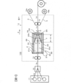
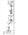
- FIG. 1 is a schematic cross-sectional view showing a prepreg manufacturing method and a coating apparatus according to an embodiment of the present invention.
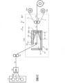
- FIG. 4 is a schematic cross-sectional view showing a prepreg manufacturing method and a coating apparatus according to another embodiment of the present invention.
- FIG. 4 is a schematic cross-sectional view showing a prepreg manufacturing method and a coating apparatus according to another embodiment of the present invention.
- FIG. 4 is a schematic cross-sectional view showing a prepreg manufacturing method and a coating apparatus according to another embodiment of the present invention.
- FIG. 2 is a cross-sectional view illustrating a structure of an application unit outlet when the application unit 20 in FIG. 1 is viewed from a direction opposite to X in FIG. 1.
- FIG. 2 is a cross-sectional view illustrating a structure of an application unit outlet when the application unit 20 in FIG. 1 is viewed from a direction opposite to X in FIG. 1.
- FIG. 2 is a cross-sectional view illustrating a structure inside the application unit when the application unit 20 in FIG. 1 is viewed from a Z direction in FIG. 1.
- FIG. 7 is a cross-sectional view illustrating a flow of a matrix resin 2 in a gap 33 in FIG. 6. It is a figure showing an example of installation of a width regulation mechanism.
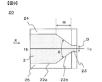
- FIG. 2 is a detailed cross-sectional view of the vicinity of an outlet of a coating unit 20 in the embodiment of FIG.
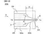
- FIG. 10 is a detailed cross-sectional view of the vicinity of an outlet of a coating unit 20b according to another embodiment different from FIG. 9.
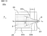
- FIG. 10 is a detailed cross-sectional view of the vicinity of an outlet of a coating unit 20c according to another embodiment different from FIG. 9.
- FIG. 9 is a cross-sectional view illustrating a structure inside the application unit when the application unit 20 in FIG. 1 is viewed from a Z direction in FIG. 1.
- FIG. 7 is a cross-sectional view illustrating
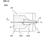
- FIG. 10 is a detailed cross-sectional view of the vicinity of an outlet of a coating unit 20d according to another embodiment different from FIG. 9. It is a detailed cross-sectional view near the exit of the application section 40 of an embodiment different from the present invention.
- FIG. 10 is a detailed cross-sectional view of a coating unit 20e according to another embodiment different from FIG. 9. It is the schematic which shows the example of the prepreg manufacturing process and apparatus using this invention. It is the schematic of an example of another prepreg manufacturing process and apparatus using this invention. It is the schematic of an example of another prepreg manufacturing process and apparatus using this invention. It is a figure showing the example of the mode provided with a plurality of application parts concerning one embodiment of the present invention.
- FIG. 10 is a detailed cross-sectional view of a coating unit 20f according to another embodiment different from FIG. 9. It is the schematic of an example of another prepreg manufacturing process and apparatus using this invention.
- FIG. 10 is a detailed cross-sectional view of a coating unit 20g according to another embodiment different from FIG. 9. It is the schematic of an example of another prepreg manufacturing process and apparatus using this invention. It is the schematic of an example of another prepreg manufacturing process and apparatus using this invention.
- FIG. 10 is a detailed cross-sectional view of an application unit 20h according to another embodiment different from FIG. 9.
- FIG. 1 is a schematic sectional view showing a prepreg manufacturing method and apparatus according to one embodiment of the present invention.
- the coating device 100 is provided between the transport rolls 14 and 15, which are transport mechanisms for moving the reinforcing fiber sheet 1b in a horizontal direction or an inclined direction, and is provided between the transport rolls 14 and 15, and the coating in which the matrix resin 2 is stored.
- a unit 20 is provided.
- the matrix resin may have fluidity by itself, or may have fluidity by containing a solvent, a plasticizer, or the like.
- a winding device 17 for the prepreg 1d is provided.
- the coating device 100 is provided with a matrix resin amount monitoring means and a matrix resin supply device. (The same applies to other examples). Further, a supply device 16a for supplying the release sheet 3 and a supply device 16b for supplying the resin film 4 are provided.
- the reinforcing fiber carbon fiber, glass fiber, metal fiber, metal oxide fiber, metal nitride fiber, organic fiber (aramid fiber, polybenzoxazole fiber, polyvinyl alcohol fiber, polyethylene fiber, polyester fiber, polyamide fiber And the like, but the use of carbon fibers is preferable from the viewpoint of the mechanical properties and light weight of the FRP.
- the reinforcing fiber sheet examples include a unidirectional material (UD base material) in which a plurality of reinforcing fibers are arranged on a surface in one direction, a reinforcing fiber in which reinforcing fibers are arranged in a multiaxial manner, or a sheet formed by random arrangement.
- UD base material unidirectional material
- the reinforcing fiber sheet examples include a unidirectional material (UD base material) in which a plurality of reinforcing fibers are arranged on a surface in one direction, a reinforcing fiber in which reinforcing fibers are arranged in a multiaxial manner, or a sheet formed by random arrangement.
- the method of forming the UD base material is not particularly limited, and may be formed using a known method. It is preferable to form a reinforcing fiber sheet in which single fibers are arranged in advance, and to further arrange the reinforcing fiber bundle to form a reinforcing fiber sheet from the viewpoint of process efficiency and uniform arrangement.
- a tow which is a tape-like reinforcing fiber bundle
- a reinforcing fiber sheet can be obtained by arranging the tape-like reinforcing fiber bundles drawn out from the bobbin.
- the creel is preferably provided with a tension control mechanism when drawing out the reinforcing fibers.
- a tension control mechanism a known mechanism can be used, and a brake mechanism or the like can be used. The tension can also be controlled by adjusting the thread guide.
- the reinforcing fiber fabric include, in addition to woven fabric and knitted fabric, those in which reinforcing fibers are two-dimensionally arranged in a multiaxial manner, and those in which reinforcing fibers such as nonwoven fabric, mat, and paper are randomly oriented.
- the reinforcing fibers can be formed into a sheet using a method such as binder application, entanglement, welding, or fusion.
- a non-crimp woven fabric, a bias structure, an entangled woven fabric, a multiaxial woven fabric, a multiple woven fabric, or the like can be used in addition to the plain woven fabric, twill fabric, and satin woven fabric.
- the woven fabric in which the bias structure and the UD base material are combined not only suppresses the deformation of the woven fabric due to the pulling in the process of applying (also referred to as application) a matrix resin and the impregnation process by the UD structure, but also performs the pseudo structure by the bias structure. It also has isotropy and is a preferred form.
- the multi-layer fabric has an advantage that the structure / characteristics of the fabric upper / lower surface and the inside of the fabric can be individually designed. In the case of a knitted fabric, warp knitting is preferred in consideration of the shape stability in the coating / impregnation step, but a blade which is a tubular knitted fabric can also be used.
- the UD substrate when giving priority to the mechanical properties of FRP, it is preferable to use a UD substrate, and the UD substrate can be produced by a known method in which reinforcing fibers are arranged in a sheet shape in one direction. .
- the method of smoothing is not particularly limited, and examples thereof include a method of physically pressing with a facing roll or the like, and a method of moving a reinforcing fiber using an air flow.
- the physical pressing method is preferred because it is simple and does not easily disturb the arrangement of the reinforcing fibers. More specifically, calendering or the like can be used.
- the method using an air flow is preferable because it not only causes less abrasion but also has the effect of widening the reinforcing fiber sheet.
- the reinforcing fiber sheet it is also preferable to guide the reinforcing fiber sheet to the liquid pool after widening the reinforcing fiber sheet from the viewpoint of efficiently producing a thin prepreg.
- the widening processing method there is no particular limitation on the widening processing method, and examples thereof include a method of mechanically applying vibration and a method of expanding the reinforcing fiber bundle by an air flow.
- a method of mechanically applying vibration there is a method of bringing a reinforcing fiber sheet into contact with a vibrating roll as described in, for example, JP-A-2015-22799.
- the vibration direction when the traveling direction of the reinforcing fiber sheet is the X axis, it is preferable to apply vibrations in the Y axis direction (horizontal direction) and the Z axis direction (vertical direction). It is also preferable to use them in combination. It is preferable that a plurality of projections are provided on the surface of the vibrating roll, because the abrasion of the reinforcing fibers by the roll can be suppressed.
- a method using an air flow see, for example, SEN-I GAKKAISHI, vol. 64, P-262-267 (2008). The described method can be used.
- the reinforcing fiber sheet is heated and then guided to the liquid pool portion, because the temperature decrease of the matrix resin can be suppressed and the viscosity uniformity of the matrix resin can be improved.
- the reinforcing fiber sheet is preferably heated to a temperature close to the matrix resin temperature.
- heating means include air heating, infrared heating, far infrared heating, laser heating, contact heating, and heating medium heating (such as steam). Means can be used. Above all, infrared heating is preferable because the apparatus is simple and the reinforcing fiber sheet can be directly heated, so that it can be efficiently heated to a desired temperature even at a high running speed.
- the matrix resin used in the present invention can be used as a resin composition containing various resins and particles described below, a curing agent, and various additives.
- the prepreg obtained by the present invention is in a state in which the matrix resin is impregnated in the reinforcing fiber sheet, and can be laminated and molded as a sheet-shaped prepreg to obtain a member made of FRP.
- the degree of impregnation can be controlled by additional impregnation after the design of the application section and the application of the matrix resin.
- the matrix resin can be appropriately selected depending on the application, but it is common to use a thermoplastic resin or a thermosetting resin.
- the matrix resin may be a molten resin heated and melted or a matrix resin at room temperature. Further, a solution or a varnish formed using a solvent may be used.
- a resin generally used for FRP such as a thermoplastic resin, a thermosetting resin, and a photocurable resin can be used. Further, these may be used as they are if they are liquids at room temperature, or may be used as solids or viscous liquids at room temperature to reduce the viscosity by heating, or may be used as a melt by melting, or a solvent. May be used as a solution or varnish.
- the thermoplastic resin is selected from a carbon-carbon bond, an amide bond, an imide bond, an ester bond, an ether bond, a carbonate bond, a urethane bond, a urea bond, a thioether bond, a sulfone bond, an imidazole bond, and a carbonyl bond in the main chain.
- a polymer having a bond can be used.
- PPS, PES, PI, PEI, PSU, PEEK, PEKK, PEAK, and the like are suitable.
- polyolefins such as polypropylene (PP), PA, polyester, PPS, and the like are preferable in order to increase molding efficiency.
- PP polypropylene
- PA polypropylene
- polyester polypropylene
- PPS polypropylene
- these may be polymers or oligomers or monomers for low viscosity and low temperature coating. Of course, these may be copolymerized depending on the purpose, or they may be mixed and used as a polymer blend or a polymer alloy.
- thermosetting resin examples include an epoxy resin, a maleimide resin, a polyimide resin, a resin having an acetylene terminal, a resin having a vinyl terminal, a resin having an allyl terminal, a resin having a nadic acid terminal, and a resin having a cyanate ester terminal.
- an epoxy resin a maleimide resin, a polyimide resin, a resin having an acetylene terminal, a resin having a vinyl terminal, a resin having an allyl terminal, a resin having a nadic acid terminal, and a resin having a cyanate ester terminal.
- thermosetting resin suitable for the present invention an epoxy resin is preferably used because of its excellent heat resistance, chemical resistance, and mechanical properties.
- an epoxy resin using an amine, a phenol, or a compound having a carbon-carbon double bond as a precursor is preferable.
- an epoxy resin using amines as a precursor various isomers of tetraglycidyldiaminodiphenylmethane, triglycidyl-p-aminophenol, triglycidyl-m-aminophenol, and triglycidylaminocresol, and phenols are used as precursors.
- the epoxy resin include, but are not limited to, alicyclic epoxy resins. Brominated epoxy resins obtained by brominating these epoxy resins are also used.
- An epoxy resin having an aromatic amine represented by tetraglycidyldiaminodiphenylmethane as a precursor has a good heat resistance and a good adhesion to a reinforcing fiber, and is most suitable for the present invention.
- Thermosetting resin is preferably used in combination with a curing agent.
- the curing agent may be a compound having an active group capable of reacting with an epoxy group.
- a compound having an amino group, an acid anhydride group, or an azide group is suitable.
- dicyandiamide, various isomers of diaminodiphenylsulfone, and aminobenzoic acid esters are suitable. More specifically, dicyandiamide is preferably used because of its excellent prepreg preservability. Further, various isomers of diaminodiphenyl sulfone are most suitable for the present invention because they give cured products having good heat resistance.
- trimethylene glycol di-p-aminobenzoate and neopentyl glycol di-p-aminobenzoate are preferably used.
- the heat resistance is lower than that of diaminodiphenyl sulfone, the tensile strength is lower. Because it is excellent, it is selected and used according to the application. It is also possible to use a curing catalyst if necessary. From the viewpoint of improving the pot life of the matrix resin, it is also possible to use a complexing agent capable of forming a complex with a curing agent or a curing catalyst.
- thermoplastic resin mixed with a thermosetting resin it is also preferable to use a thermoplastic resin mixed with a thermosetting resin.
- a mixture of a thermosetting resin and a thermoplastic resin gives better results than using the thermosetting resin alone. This is because the thermosetting resin is generally capable of low pressure molding by an autoclave while having a brittle defect, whereas the thermoplastic resin is generally difficult to perform low pressure molding by an autoclave while having the advantage of being tough. This is because they exhibit a trade-off characteristic, that is, they can be used in combination to balance physical properties and moldability.
- inorganic particles or organic particles can be contained in the matrix resin or the resin film.
- the type of the inorganic particles can be selected according to the purpose and is not particularly limited.For example, in order to impart conductivity, heat conductivity, thixotropy, and the like, carbon-based particles, boron nitride particles, titanium dioxide particles, silicon dioxide particles, and the like. Can be suitably used.
- the type of the organic particles may be selected according to the purpose, and is not particularly limited. Particularly, the use of polymer particles is preferable because the toughness, impact resistance, and vibration damping properties of the obtained FRP can be improved.
- the glass transition temperature (Tg) or the melting point (Tm) of the polymer particles be higher than the matrix resin temperature by 20 ° C. or more, because the shape of the polymer particles can be easily maintained in the matrix resin.
- the Tg of the polymer particles can be measured using a temperature-modulated DSC under the following conditions.
- the temperature modulation DSC device Q1000 manufactured by TA Instruments or the like is suitable, and it can be used after being calibrated with high-purity indium in a nitrogen atmosphere.
- the measurement conditions are as follows: the temperature rise rate is 2 ° C./min, and the temperature modulation condition is a cycle of 60 seconds and an amplitude of 1 ° C.
- the reversible component is separated from the total heat flow obtained in this way, and the temperature at the middle point of the step signal can be set to Tg.
- Tm is measured by a normal DSC at a heating rate of 10 ° C / min, and the peak top temperature of a peak-like signal corresponding to melting can be defined as Tm.
- the polymer particles do not dissolve in the matrix resin.
- polymer particles for example, appropriate ones can be used with reference to the description in WO2009 / 142231 pamphlet and the like.
- polyamide or polyimide can be preferably used, and polyamide, which can greatly improve impact resistance due to excellent toughness, is most preferable.
- Polyamides such as polyamide 12, polyamide 11, polyamide 6, polyamide 66, polyamide 6/12 copolymer, and the epoxy compound described in Example 1 of JP-A-01-104624 are semi-IPN (polymer interpenetrating network structure). Polyamide (semi-IPN polyamide) or the like can be suitably used.
- the shape of the thermoplastic resin particles may be a spherical particle, a non-spherical particle, or a porous particle, but a spherical shape is particularly preferable in the production method of the present invention since the flow characteristics of the resin are not deteriorated. Further, a spherical shape is a preferable embodiment in that there is no starting point of stress concentration and high impact resistance is given.
- polyamide particles include SP-500, SP-10, TR-1, TR-2, 842P-48, 842P-80 (all manufactured by Toray Industries, Inc.) and "Orgasol (registered trademark)" 1002D. , 2001UD, 2001EXD, 2002D, 3202D, 3501D, 3502D (all manufactured by Arkema Co., Ltd.), "Grillamide (registered trademark)” TR90 (manufactured by Mazaverke Co., Ltd.), "TROGAMID (registered trademark)” CX7323, CX9701 , CX9704 (manufactured by Degussa Co., Ltd.) and the like can be used. These polyamide particles may be used alone or in combination of two or more.
- the number average particle size of the polymer particles is preferably in the range of 5 to 50 ⁇ m, more preferably in the range of 7 to 40 ⁇ m, and still more preferably in the range of 10 to 30 ⁇ m.
- the number average particle diameter is 5 ⁇ m or more, the particles do not enter the bundle of the reinforcing fibers, and can remain in the reinforcing fiber interlayer resin layer of the obtained fiber-reinforced composite material.
- the matrix resin used in the present invention it is preferable to select an optimum viscosity from the viewpoint of processability and stability. Specifically, when the viscosity is in the range of 1 to 60 Pa ⁇ s, the dripping at the constricted portion exit can be suppressed, and the high-speed running property and the stable running property of the reinforcing fiber sheet can be improved, which is preferable.
- the viscosity refers to a value measured at a matrix resin temperature in a liquid reservoir at a strain rate of 3.14 s -1 .
- a viscoelasticity measuring device such as a parallel disk type or a cone type can be used.
- the viscosity of the matrix resin is more preferably 5 to 30 Pa ⁇ s.
- the horizontal direction is shown as the X direction in FIG.
- the reinforcing fiber sheet can be passed in the inclined direction, and traveling in the inclined direction and traveling in the horizontal direction can be combined.
- the tilt direction refers to a direction intermediate between the horizontal direction and the vertical direction. More specifically, the horizontal direction or the inclined direction can be in a range of ⁇ 80 ° to + 80 ° with the horizontal plane being 0 °.
- the running direction of the reinforcing fiber sheet in the constricted part in the application part is in the range of ⁇ 30 ° to + 30 ° with the horizontal plane being 0 °, it becomes possible to incorporate the reinforcing fiber sheet into the existing prepreg manufacturing equipment, and from the viewpoint of versatility of equipment Is preferred.
- the running direction of the reinforcing fiber sheet in the constricted part in the application part is more preferably from ⁇ 15 ° to + 15 ° with the horizontal plane as 0 °.
- the reinforcing fiber sheet is introduced into the application section obliquely downward, and is also described as traveling in the vertical and oblique directions when traveling between the direction changing members in the application section.
- the running direction of the reinforcing fiber sheet is horizontal in a portion where the cross-sectional area is continuously reduced or in a narrow portion.
- the running path of the reinforcing fiber sheet 1b is linearized, and the reinforcing fiber sheet 1b is disturbed due to the thickness of the reinforcing fiber sheet 1b. Is less likely to occur.
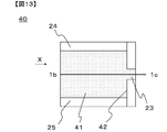
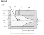
- the application section 20 includes an exit side member 29 facing the main body with a predetermined gap D therebetween, and the wall side members 21a and 21b on the introduction side of the reinforcing fiber sheet 1b, and the exit side member 29 on the exit side. .
- a liquid reservoir 22 and a slit-shaped constriction located on the outlet side of the liquid reservoir 22 and having a cross-sectional area smaller than the maximum cross-sectional area of the liquid reservoir 22.
- a part 23 is formed.
- the reinforcing fiber sheet 1b introduced into the liquid pool section 22 travels in the horizontal direction while accompanying the matrix resin 2 around the reinforcing fiber sheet 1b.
- the accompanying matrix resin 2 is gradually compressed, and the outlet of the liquid reservoir 22 is , The pressure of the matrix resin 2 increases.
- the accompanying liquid flow becomes more difficult to flow in the outlet direction, flows toward the upper member 24 and the lower member 25, and then flows toward the upper member 24 and the lower member 25.
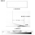
- the increased liquid pressure has an effect that the matrix resin 2 is easily impregnated into the reinforcing fiber sheet 1b.
- This is based on the property (Darcy's law) that when a matrix material is impregnated into a porous body such as a reinforcing fiber bundle, the degree of impregnation increases with the pressure of the matrix resin. Also in this case, when the reinforcing fiber sheet 1b is run at a higher speed, the hydraulic pressure is further increased, so that the impregnation effect can be further enhanced.
- the matrix resin 2 is impregnated with the bubbles remaining inside the reinforcing fiber sheet 1b by gas / liquid displacement, and the bubbles have a continuous cross-sectional area with the portion 22a whose cross-sectional area does not decrease due to the circulating flow T and buoyancy. Are gathered near the boundary of the portion 22b. For this reason, it is preferable to install a degassing mechanism 26 for degassing air bubbles from the matrix resin 2 in the vicinity. More specifically, the installation position of the degassing mechanism is preferably within a range of 5 cm or less from the boundary position between the portion 22a where the cross-sectional area does not decrease and the portion 22b where the cross-sectional area continuously decreases.
- Patent Document 3 impregnation is performed by a plurality of fixed guides, and it is considered that bubbles are generated in a wide range.
- a degassing mechanism is not necessarily installed in the vicinity thereof, and the removal of bubbles is not sufficient. There was a possibility.
- the reinforcing fiber sheet 1b is automatically centered at the center of the gap D by the increased hydraulic pressure, and the reinforcing fiber sheet 1b does not directly rub against the wall of the liquid reservoir 22 or the narrowed portion 23. It also has the effect of suppressing the generation of fluff. This is because, when the reinforcing fiber sheet 1b approaches one of the gaps D due to a disturbance or the like, the matrix resin 2 is pushed into the narrower gap on the approaching side and compressed, so that the hydraulic pressure increases on the approaching side. Then, the reinforcing fiber sheet 1b is pushed back to the center of the gap D.
- the constriction 23 is designed to have a smaller cross-sectional area than the maximum cross-sectional area of the liquid reservoir 22.
- the length of the quasi-plane of the reinforcing fiber sheet 1b in the perpendicular direction is small, that is, the cross-sectional area is small because the interval between the members is small. This is because the impregnation and the self-centering effect can be obtained by increasing the hydraulic pressure in the constricted portion 23 as described above.
- the cross-sectional shape of the entrance portion of the constricted portion 23 be made to match the cross-sectional shape of the surface of the liquid reservoir portion 22 in contact with the narrowed portion 23, from the viewpoint of the running property of the reinforcing fiber sheet 1b and the flow control of the matrix resin 2.
- the constriction 23 may be slightly larger if necessary.
- the reinforcing fiber sheet 1b runs completely in the horizontal direction, but is not limited to this, and the above-described effects of collecting fluff and discharging bubbles can be obtained.
- 1b may travel in the inclined direction in the application section 20 within a range in which the vehicle can run stably continuously. Further, the application section 20 can be inclined.
- the total amount of the matrix resin 2 applied to the reinforcing fiber sheet 1b can be controlled by the gap D of the narrowed portion 23.
- the gap D may be adjusted to be wide.
- FIG. 1 illustrates a case where one reinforcing fiber sheet is introduced into the application section from the horizontal direction.
- the introduction of the reinforcing fiber sheet into the application section is not limited to this, and a plurality of reinforcing fiber sheets may be used as necessary.
- the introduction direction may be the inclined direction. This will be described with reference to FIGS.
- one reinforcing fiber sheet 1b runs obliquely downward from above and is introduced into the application section 20 through the opening 30.
- the running direction of the reinforcing fiber sheet 1 b is changed to a horizontal direction by the direction changing member 31, and the reinforcing fiber sheet 1 b is pulled out from the narrowed portion 23.
- a special sealing mechanism is not required, and the apparatus can be simplified.
- the opening it is also possible to equip the opening with a sealing mechanism as required for various purposes such as filling the liquid pool with an inert gas.
- a sealing mechanism it is preferable that at least the surface of the direction changing member 31 that is in contact with the reinforcing fiber sheet 1b is formed as a curved surface.
- the direction changing member 31 is preferably fixed.
- the direction changing member 31 is preferably a fixed bar having a curved surface, and its cross-sectional shape can be exemplified by a circle, an ellipse, a saddle, and the like.
- a curved surface and a flat surface may be mixed in a portion where the direction changing member 31 and the reinforcing fiber sheet 1b are in contact with each other, but when the ground start portion and the end portion of the reinforcing fiber sheet 1b are curved surfaces, generation of fluff can be suppressed. ,preferable.
- a rotatable roller can be used from the viewpoint of suppressing abrasion between the reinforcing fiber sheet 1b and the direction changing member 31.
- impregnation may be performed by replacing the gas in the reinforcing fiber sheet 1b with the matrix resin 2.
- the impregnation can be promoted more efficiently by pressing the plurality of direction changing members 31 at an angle.
- the installation position of the direction changing member 31 is 1 cm or more from the boundary position between the portion 22a where the cross-sectional area does not decrease and the portion 22b where the cross-sectional area continuously decreases. It is preferable to use the portion 22a that does not decrease.
- two reinforcing fiber sheets 1 b run obliquely downward from above and are introduced into the coating section 20 through the opening 30.
- the running direction of the two reinforcing fiber sheets 1b is changed by the direction changing member 31 to the horizontal direction, and after the two sheets are stacked, the two reinforcing fiber sheets 1b are pulled out from the narrowed portion 23.
- the matrix resin 2 is contained and laminated between the two reinforcing fiber sheets 1b, the impregnation becomes easier to progress in the portion 22b and the constricted portion 23 where the cross-sectional area is continuously reduced, which is preferable.
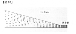
- the length H of the portion 22b where the cross-sectional area is continuously reduced is preferably 10 mm or more, from the viewpoint of suppressing excessive swelling in the thickness direction of the reinforcing fiber sheet 1b laminate, more preferably. Is 30 mm or more. If there is no portion 22b where the cross-sectional area is continuously reduced, the reinforcing fiber sheet 1b laminate containing the matrix resin 2 therein and having an excessive swelling in the thickness direction is rapidly introduced into the constricted portion 23. Therefore, the extra matrix resin 2 cannot be discharged, and if the gap D is thicker than the gap D, the matrix resin 2 is easily clogged.
- the traveling speed of the reinforcing fiber sheet 1b When the length H of the continuously decreasing portion 22b is less than 10 mm and the traveling speed of the reinforcing fiber sheet 1b is sufficiently low, the thickness of the reinforcing fiber sheet 1b laminate can be reduced. When the speed is increased, the effect becomes insufficient, and the clogging is likely to occur. As described above, when H is 30 mm or more, the traveling speed can be increased to 20 m / min or more.
- the length C of the liquid pool portion can be reduced within a range in which the reinforcing fiber sheet can travel, but specifically, the length C is set to 400 mm or less in order to reduce the volume of the liquid pool portion. Is preferred. More preferably, it is 200 mm or less.
- two reinforcing fiber sheets 1b run obliquely downward from above and are introduced into the coating section 20 through the opening 30. Then, the two reinforcing fiber sheets 1 b are impregnated while passing through the plurality of direction changing members 31, and are finally pulled out from the narrowed portion 23 after the two sheets are laminated.
- the shape and the number of the direction changing members 31 for promoting the impregnation can be variously selected according to the purpose.
- the contact length between the direction changing member 31 and the reinforcing fiber sheet 1b and the angle (wrap angle) formed between both ends of the contact portion and the center of the direction changing member 31 can be selected according to the purpose.
- FIGS. 3 and 4 show an example in which the number of the reinforcing fiber sheets 1b is two, but it is needless to say that any number of the reinforcing fiber sheets 1b can be three or more.
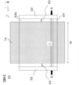
- FIG. 5 is a view of the application unit 20 viewed from the direction opposite to X in FIG.
- the coating portion 20 is provided with a side wall member 32 for preventing the matrix resin 2 from leaking from both ends in the arrangement direction of the reinforcing fiber sheet 1b, and a narrow portion is formed in the space surrounded by the outlet side member 29 and the side wall member 32.
- outlets 28 are formed.
- the outlet 28 has a slit shape, and the sectional aspect ratio (U / D in FIG. 5) may be set according to the shape of the reinforcing fiber sheet 1b to which the matrix resin 2 is to be applied.
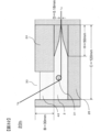
- FIG. 6 is a cross-sectional view illustrating the structure inside the coating unit when the coating unit 20 is viewed from the Z direction.
- the upper surface member 24 is omitted for easy viewing of the drawing.
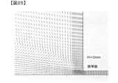
- FIG. 7 shows the flow of the matrix resin 2 in the gap 33 between the reinforcing fiber sheet 1b and the side wall member 32. If the gap 33 between the reinforcing fiber sheet 1b and the side wall member 32 is large, a vortex flows in the matrix resin 2 in the direction of R.
- the vortex flow R becomes outward flow (Ra) near the boundary between the portion 22b where the cross-sectional area is continuously reduced and the constricted portion 23 in the liquid reservoir 22, so that the reinforcing fiber sheet arranges the reinforcing fiber bundle.
- the flow is in the direction of tearing (breaking of the sheet-like reinforcing fiber bundle).
- the width of the width W of 1b and the following equation (1) is the width of the width W of 1b and the following equation (1).
- an interval L between the left and right side wall members 32 (the width of the end of the liquid pool portion.
- the width L is the width of the terminal of the liquid pool portion).
- the width W of the sheet-shaped reinforcing fiber bundle at the outlet of the constricted portion is set so as to satisfy the relationship of the above equation (1).
- the lower limit of L is not less than W-5 (mm) from the viewpoint of improving the uniformity of the dimension in the width direction of the prepreg 1d.
- this width regulation is, from the viewpoint of suppressing the generation of the vortex R due to high hydraulic pressure at the outlet side of the portion 22b where the cross-sectional area continuously decreases, at least the G at the outlet side of the portion 22b where the cross-sectional area continuously decreases. (FIG. 6). Further, when the width regulation is more preferably performed in the entire area of the portion 22b where the cross-sectional area is continuously reduced, more preferably in the entire area of the liquid reservoir 22, the generation of the vortex R can be almost completely suppressed. As a result, it is possible to almost completely suppress cracks and end breaks in the reinforcing fiber sheet.
- the width regulation may be limited to only the liquid pool portion 22, but if the narrow portion 23 is similarly performed, the primary prepreg 1c It is preferable from the viewpoint of suppressing the excessive matrix resin 2 from being applied to the side surface.
- width regulation mechanisms 34a and 34b may be provided between the side wall members 32, and the width regulation may be performed by such a mechanism.
- the width (W) of the reinforcing fiber sheet 1b at the outlet of the constricted portion 23 and the width (L2) regulated by the width regulating mechanism at the exit side end of the width regulating mechanism is L2 ⁇ W + 10 (mm). It is more preferable that L2 ⁇ W + 2 (mm).
- the lower limit of L2 is preferably adjusted to be not less than W-5 (mm) from the viewpoint of improving the uniformity of the dimension in the width direction of the prepreg 1d.
- L in the above equation (1) is regarded as L2.
- the shape and material of the width regulating mechanism are not particularly limited, but a plate-shaped bush is simple and preferable. Further, by having a width slightly smaller than the distance between the upper surface member 24 and the lower surface member 25 (refer to FIG. 8, the vertical length of the width regulating mechanisms 34 a and 34 b in the figure viewed from the X direction). This is preferable because the horizontal flow of the matrix resin 2 can be prevented. On the other hand, it is possible to suppress the stagnation of the matrix resin 2 in the liquid pool by forming the shape along the internal shape of the liquid pool 22 from the middle portion of the width regulating mechanism to the outlet end, thereby preventing the matrix resin 2 from deteriorating. It is preferable because it can be suppressed.
- FIG. 8 shows an example of a plate-shaped bush as the width regulating mechanism.
- FIG. 8 shows an example in which L2 is constant from the vicinity of the boundary between the portion 22a where the cross-sectional area does not decrease and the portion 22b where the cross-sectional area continuously decreases to the exit.
- the width restricted by the control may be changed.
- the width regulating mechanism can be fixed to the application section 20 by an arbitrary method.
- the liquid pressure is increased in the running direction of the reinforcing fiber sheet by continuously decreasing the cross-sectional area in the running direction of the reinforcing fiber sheet 1b in the liquid reservoir 22.
- the continuous decrease in the cross-sectional area in the running direction of the reinforcing fiber sheet is not particularly limited as long as the hydraulic pressure can be continuously increased in the running direction.
- the liquid reservoir may have a curved shape such as a tapered shape (linear shape) or a trumpet shape.
- the cross-sectional area decreasing portion may be continuous over the entire length of the liquid pool portion, or may include a portion where the cross-sectional area does not decrease or a portion which expands conversely as long as the object and effects of the present invention can be obtained. You may go out. These will be described in detail below with reference to FIGS. 9 to 12. 9 to 12, the vicinity of the outlet is shown, and the vicinity of the introduction portion of the reinforcing fiber sheet 1b, the degassing mechanism, and the like are omitted.
- FIG. 9 is a detailed cross-sectional view of the coating section 20 of FIG.
- the opening angle ⁇ of the taper is preferably small, specifically, an acute angle (90 ° or less).
- ⁇ is more preferably 30 ° or less.
- FIG. 10 is a detailed cross-sectional view of the application section 20b of another embodiment different from FIG. It is the same as the application section 20 in FIG. 9 except that the shape of the portion 22b where the cross-sectional area is continuously reduced is a two-step tapered shape.
- the portion 22b where the cross-sectional area of the liquid reservoir 22 is continuously reduced may be configured by a multi-stage taper portion having two or more stages. At this time, it is preferable to make the opening angle ⁇ of the tapered portion closest to the constricted portion 23 an acute angle from the viewpoint of enhancing the compression effect. Also in this case, it is preferable that the length H of the portion 22b where the cross-sectional area of the liquid reservoir 22 is continuously reduced is 10 mm or more.
- the length H of the portion 22b where the cross-sectional area is continuously reduced is 30 mm or more.
- the portion 22 b where the cross-sectional area of the liquid reservoir 22 is continuously reduced is formed into a multi-stage tapered portion, so that the volume of the matrix resin 2 that can be stored in the liquid reservoir 22 is maintained while the constriction portion 23 is maintained. Can be further reduced. As a result, the liquid pressure generated on the outlet side of the liquid reservoir 22 is further increased, and the effect of eliminating fluff and the effect of impregnating the matrix resin 2 can be further enhanced.
- FIG. 11 is a detailed cross-sectional view of the application unit 20c according to another embodiment different from FIG. It is the same as the application section 20 in FIG. 9 except that the shape of the portion 22b where the cross-sectional area is continuously reduced is stepped. As described above, if there is a portion 22b having a continuously decreasing cross-sectional area at the most outlet side of the liquid reservoir 22, the effect of increasing the liquid pressure, which is the object of the present invention, can be obtained.
- the portion may include a portion 22c whose cross-sectional area decreases intermittently.
- FIG. 12 is a detailed cross-sectional view of the application unit 20d according to another embodiment different from FIG. It is the same as the application section 20 in FIG. 9 except that the shape of the portion 22b where the cross-sectional area is continuously reduced is a trumpet shape (curved shape).
- the portion 22b where the cross-sectional area of the liquid reservoir 22 continuously decreases is tapered (linear), but is not limited to this.
- a trumpet shape (curved shape) as shown in FIG. May be.
- the portion 22b in which the cross-sectional area of the liquid reservoir 22 is continuously reduced has a trumpet shape, the virtual tangent at the most outlet side of the portion 22b in which the cross-sectional area of the liquid reservoir 22 is continuously reduced. It is preferable to make the opening angle ⁇ of the first angle acute.
- the cross-sectional area of the liquid reservoir does not necessarily have to be smoothly reduced unless the object of the present invention is impaired.
- FIG. 13 is a detailed cross-sectional view of the application section 40 of another embodiment different from the present invention.
- the liquid pool 41 in FIG. 13 does not include a portion where the cross-sectional area continuously decreases in the running direction (X direction) of the reinforcing fiber sheet, and is cut off at the boundary 42 with the narrowed portion 23.
- the area is discontinuous and sharply reduced. Therefore, the reinforcing fiber sheet 1b is easily clogged.
- the matrix resin stored in the liquid reservoir is easily denatured by heat or the like, it is preferable to reduce the volume of the liquid reservoir as much as possible from the viewpoint of the quality stability of the obtained prepreg and the process stability of coating. preferable.
- the volume of the liquid reservoir is excessively reduced, it may be assumed that the supply of the matrix resin to the liquid reservoir is likely to be insufficient with respect to the applied amount. In such a case, there is a possibility that the circulating flow in the liquid pool portion becomes uneven, and the running property of the reinforcing fiber sheet becomes poor.
- the storage portion 43 for this purpose can be formed by, for example, the wall member 21 and the upper surface member 24, but is not limited thereto.
- the distance B defined by the lower surface of the upper surface member 24 and the upper surface of the storage portion 43 in FIG. 14 is preferably 100 mm or less, and the traveling path of the reinforcing fiber sheet 1b. In consideration of the degree of freedom of design, it is preferably 50 mm or less.
- FIG. 1 shows a case where a resin film 4 is provided on one surface and a release sheet 3 is provided on the other surface.
- the resin film 4 is supplied from the supply device 16b
- the release sheet 3 is supplied from the supply device 16a
- the release film 3 can be stacked on the transport roll 15 on the primary prepreg 1c.
- FIG. 1 shows an example in which one resin film 4 and one release sheet 3 are laminated, depending on the purpose, only the resin film 4 or only the release sheet 3 is laminated.
- the resin film may be laminated on both sides, or the release sheet may be laminated on both sides. Further, a mode in which the resin film and the release sheet are laminated may be employed.
- the type of resin constituting the resin film can be appropriately selected according to the purpose, and may be a mixture of a plurality of types of resins. When two resin films are used, they may be the same resin film or different types of resin films. When two release sheets are used, they may be of the same type or different types.
- the release sheet a sheet formed of a polymer having a release action or a sheet in which a release layer is provided on a substrate, for example, a sheet in which a release layer is laminated on the resin film described above is used. It can also be supplied.
- the above description is not limited to the embodiment of FIG. 1, and the same can be applied to the embodiments of other drawings.
- the resin used for the resin film is not particularly limited, and can be appropriately selected depending on the purpose.
- the resin used as the resin film may be a single resin, a blend of different polymers, or a resin composition that is a blend of various components.
- the resin film used here can contain the particles.
- a matrix resin containing particles is used in the application step, the viscosity tends to increase, and the uniformity of application may be deteriorated during high-speed running of the reinforcing fiber sheet. For this reason, it is preferable to apply the particles in the resin film applying step because the high-speed running stability of the reinforcing fiber sheet in the applying step is improved.
- the resin film containing particles may be a resin film made of a matrix resin.
- the matrix resin can be applied while the particles are applied separately from the coating step, so that it is efficient.
- the matrix resin of the matrix resin containing particles may be the same as or different from the matrix resin component used in the coating step.
- the components of the matrix resin used in the coating step and the matrix resin to be formed into a resin film can be adjusted in consideration of the high-speed running stability in the coating step and the pot life in storage in the coating section.
- a certain resin component can be taken out of the matrix resin and formed into a resin film.
- a thermoplastic resin can be blended with a matrix resin mainly composed of a thermosetting resin to improve the toughness of the resin.
- this thermoplastic resin may increase the viscosity of the matrix resin.
- application stability can be improved by applying the thermoplastic resin as a resin film to the primary prepreg without using it as a component of the matrix resin applied in the application step.
- PES, PEI, PI, and the like are often used as such a thermoplastic resin.
- such a thermoplastic resin film may be a self-supporting film that does not require a support in some cases, and is useful from the viewpoint that the support can be omitted.
- the method for obtaining the resin film is not particularly limited, and a known method can be used.For example, using a known coater such as a roll coater, a comma coater, a knife coater, a die coater, and a spray coater, film formation is performed. You can do it. Further, if necessary, a resin can be applied on a support such as a release sheet to form a film.
- a known coater such as a roll coater, a comma coater, a knife coater, a die coater, and a spray coater.
- a traveling mechanism for transporting the reinforcing fiber sheet or the prepreg of the present invention As a traveling mechanism for transporting the reinforcing fiber sheet or the prepreg of the present invention, a known roller or the like can be suitably used. In the present invention, since the reinforcing fiber sheet is conveyed in the horizontal direction or the inclined direction, it is preferable to arrange rollers before and after the application section.
- the running path of the reinforcing fiber sheet is as straight as possible in order to suppress the arrangement disorder and the fluffing of the reinforcing fiber.
- the prepreg is often a sheet-like integrated body that is a laminate with a release sheet, but in the conveying step of the prepreg, if there is a bent portion, wrinkles may occur due to a difference in circumference between the inner layer and the outer layer. Therefore, it is preferable that the traveling path of the sheet-shaped integrated object is as straight as possible. From this viewpoint, it is preferable to use a nip roll in the traveling path of the sheet-like integrated object.
- Whether the S-shaped roll or the nip roll is used can be appropriately selected according to the manufacturing conditions and the characteristics of the product.
- a high tension take-up device for drawing out the prepreg from the application section downstream of the application section. This is because high frictional force and shear stress are generated between the reinforcing fiber sheet and the matrix resin in the application section, and it is preferable to generate a high take-up tension downstream of the process in order to overcome the drawback and draw out the prepreg. It is.
- a high tension take-up device a nip roll, an S-shaped roll, a belt press, or the like can be used. In any case, by increasing the frictional force between the device and the prepreg, slip can be prevented and stable running can be achieved.
- the belt press is reliable.
- the S-shaped roll is preferable because the frictional force can be easily controlled by the roll diameter and the contact length.
- a release sheet feeding device or a winder can be used as appropriate, and as such a device, a known device can be used. It is preferable to provide a mechanism capable of feeding back the winding tension or feeding back the winding speed from the viewpoint of stable running of the sheet.
- Additional impregnation In order to adjust the degree of impregnation to a desired degree, it is also possible to combine a means for further increasing the degree of impregnation using an impregnating apparatus separately after coating with the present invention.
- additional impregnation after application is referred to as additional impregnation
- an apparatus therefor is referred to as an additional impregnation apparatus.
- the device used as the additional impregnation device is not particularly limited, and can be appropriately selected from known devices according to the purpose.
- a laminate of a sheet-like carbon fiber bundle and a resin is preheated by a hot plate to sufficiently soften the resin on the sheet-like carbon fiber bundle.
- the impregnation can also be advanced by using a device that presses with a heated nip roll.
- the temperature of the hot plate for preheating, the surface temperature of the nip roll, the linear pressure of the nip roll, and the diameter and number of the nip rolls can be appropriately selected so as to obtain a desired impregnation degree.
- FIG. 1 shows an example in which the prepreg sheet runs in an S-shape, but if impregnation is possible, the contact length between the sheet and the roll, such as a U-shape, V-shape or ⁇ -shape, is described. May be adjusted.
- the impregnation pressure is increased to increase the degree of impregnation, it is also possible to add an opposing contact roll. Further, as shown in FIG.
- a heated nip roll or a heated S-shaped roll can be used, but the roll diameter, the set pressure, and the contact length between the primary prepreg and the roll can be reduced as compared with a normal impregnating device. This is preferable because not only the size can be reduced but also the power consumption and the like can be reduced.
- a release sheet to the primary prepreg before the primary prepreg enters the simple additional impregnating apparatus, because the running property of the primary prepreg is improved.
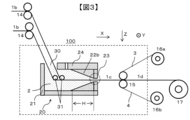
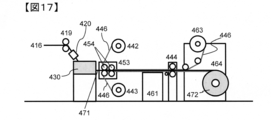
- FIG. 17 shows an example of a prepreg manufacturing process equipped with a simple additional impregnation device.
- a simple additional impregnation device 453 is provided immediately after the application section 430.
- the simple additional impregnation device 453 shows an example of a nip roll, but the nip roller preferably has a heating mechanism.
- the number of nip rolls can be appropriately selected depending on the purpose, but from the viewpoint of simplification of the process, three or less nip rolls are preferable (FIG. 17 shows an example of two nip rolls).
- the nip roller is provided with a driving device from the viewpoint that tension control of prepreg conveyance is easy.
- the nip pressure can be appropriately adjusted according to the desired degree of impregnation.
- the nip roll surface is subjected to an appropriate release treatment so that the primary prepreg does not stick, or a release sheet is inserted between the primary prepreg and the nip roll.
- the release sheet can be inserted from the application section 430 side and the release sheet can be separated from the primary prepreg by the roll on the high tension take-off device 444 side.
- the separated release sheet may be wound up as it is, or may be run again on the circuit so as to be inserted again from the application section 430 side.
- the prepreg referred to in the present invention is a reinforced fiber sheet provided with a matrix resin, and is a two-dimensional sheet-like intermediate substrate for producing FRP.
- a so-called drawn material is also included in the prepreg without departing from this meaning.
- the width of the prepreg is not particularly limited, and the prepreg may be manufactured in a narrow tape shape or a wide width up to about 2 m.
- the thickness of the prepreg is not particularly limited, but is generally about 0.05 mm to 1 mm.
- the impregnation ratio of the matrix resin is desirably 10% or more.
- the state of the impregnation of the matrix resin can be confirmed by tearing the collected prepreg and visually observing the inside, and can be more quantitatively evaluated by, for example, a peeling method.
- the impregnation rate of the matrix resin by the peeling method can be measured as follows. That is, the collected prepreg is sandwiched between adhesive tapes, and the prepreg is peeled off to separate the reinforcing fibers to which the matrix resin has adhered from the reinforcing fibers to which the matrix resin has not adhered.
- the ratio of the mass of the reinforcing fibers to which the matrix resin has adhered to the mass of the entire reinforcing fiber sheet put in can be taken as the impregnation rate of the matrix resin by the peeling method.
- the degree of impregnation can also be evaluated based on the water absorption due to the capillary action of the prepreg. Specifically, in accordance with the method described in JP-T-2016-510077, the prepreg can be cut into 10 cm ⁇ 10 cm, one side of which is 5 mm, and can be calculated from the change in mass when immersed in water for 5 minutes. .
- the width of the prepreg is not particularly limited, and may be a wide width of about several tens cm to 2 m, or a tape having a width of several mm to several tens mm.
- the width can be selected according to the application.
- devices called ATL (Automated Tape Laying) or AFP (Automated Fiber Placement) for automatically laminating narrow-width prepregs and prepreg tapes have been widely used in order to streamline the prepreg lamination process. Therefore, it is also preferable that the width is adjusted to this.
- ATL often uses narrow prepregs having a width of about 7.5 cm, about 15 cm, or about 30 cm.
- AFP often uses prepreg tapes having a width of about 3 mm to about 25 mm.
- the width of the coating portion used in the present invention can be adjusted so as to have a desired width from the beginning. For example, when manufacturing a narrow prepreg having a width of 30 cm for ATL, the width of the application section outlet may be adjusted accordingly. In addition, in order to manufacture this efficiently, it is preferable to manufacture the product with a product width of 30 cm. When a plurality of such manufacturing devices are arranged in parallel, the same traveling device / transport device, various rolls, and a winder are used. The prepreg of the line can be manufactured.
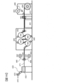
- FIG. 18 shows an example in which five application units are connected in parallel in one example.
- the five reinforced fiber sheets 416 may pass through five independent application parts 430 to obtain five primary prepregs 471, or the application parts 430 may be integrated in a parallel direction. It may be.
- the coating unit 430 may be provided with five independent width control mechanisms and five coating unit outlet widths.
- a reinforcing fiber sheet in the form of a tape-shaped reinforcing fiber bundle having about 1 to 4 yarns is formed and passed through a coating section whose width has been adjusted so as to obtain a desired tape width. You can also get it.
- the accuracy of the tape width is often required from the viewpoint of controlling the lateral overlap between the tapes. For this reason, it is preferable to more strictly control the outlet width of the application section.
- the above L, L2, and W satisfy the relationship of L ⁇ W + 1 mm and / or L2 ⁇ W + 1 mm. .
- the method of slitting the prepreg is not particularly limited, and a known slit device can be used. After winding the prepreg once, it may be installed in the slit device again to perform slitting, or for efficiency, a slit step may be arranged continuously from the prepreg production step without winding the prepreg once. Also, in the slitting step, a wide prepreg of 1 m or more may be directly slit to a desired width, or once cut and divided into narrow prepregs of about 30 cm, and then slit again to a desired width. good.
- a release sheet may be supplied independently, or one wide release sheet may be supplied.
- a plurality of prepregs may be stacked. The end in the width direction of the prepreg thus obtained can be cut off and supplied to an ATL or AFP device.
- the matrix resin component resin in the case of FRP
- adhering to the slit cutter blade can be reduced, and the cleaning cycle of the slit cutter blade is extended. There is also an advantage that you can do it.
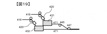
- FIG. 19 shows an example of an embodiment in which prepregs are stacked using two application sections.
- the two primary prepregs 471 pulled out from the first coating unit 431 and the second coating unit 432 pass through the direction change roll 445 and are stacked by the stacking roll 447 downstream thereof. At this time, it is preferable to position the release sheet between the primary prepreg 471 and the direction change roll, because it is possible to suppress the prepreg from sticking to the roll and to stabilize traveling.
- the direction change roll can be replaced with a direction change guide or the like subjected to a release treatment.By using such a laminated prepreg, the efficiency of the prepreg laminating step can be improved, This is effective, for example, when manufacturing a thick FRP. Further, it is expected that the toughness and impact resistance of the FRP will be improved by laminating thin prepregs in multiple layers, and by applying the present production method, thin multilayer prepregs can be efficiently obtained. Further, by easily laminating different types of prepregs, a hetero-bonded prepreg having added functionality can be easily obtained. In this case, it is possible to change the type and fineness of the reinforcing fiber, the number of filaments, mechanical properties, fiber surface characteristics, and the like.
- a different matrix resin resin in the case of prepreg.
- a prepreg having a different thickness or a heterojunction prepreg obtained by laminating prepregs having different mechanical properties can be used.
- a resin having excellent mechanical properties is provided in the first application section, and a resin having excellent tack properties is provided in the second application section.
- a resin without particles can be applied in the first application section, and a resin containing particles can be applied in the second application section.
- a plurality of application sections are arranged in parallel to the running direction of the reinforcing fiber sheet, that is, a plurality of application sections are arranged in parallel in the width direction of the reinforcing fiber sheet.
- a plurality of application portions can be arranged in series in the running direction of the reinforcing fiber sheet.
- the type of matrix resin can be changed in the thickness direction of the primary prepreg.
- running stability and high-speed running performance can be improved by changing the application conditions depending on the application section.
- a resin having excellent mechanical properties is applied in the first application section
- a resin having excellent tack properties is applied in the second application section
- a prepreg that can achieve both mechanical properties and tackiness by laminating them is easily provided.
- a resin without particles can be applied in the first application section, and a resin containing particles can be applied in the second application section.
- the manufacturing method of the present invention is not only capable of improving the efficiency and stabilization of the manufacturing, but also is capable of improving the performance and functioning of the product, and is a manufacturing method excellent in expandability.
- the matrix resin is stored in the coating section, but it is preferable to appropriately supply the matrix resin because the coating proceeds.
- the mechanism for supplying the matrix resin to the application section is not particularly limited, and a known device can be used. It is preferable that the matrix resin be continuously supplied to the application section because the running of the reinforcing fiber sheet can be stabilized without disturbing the liquid level above the application section.
- the self-weight can be supplied as a driving force from a tank storing the matrix resin, or can be supplied continuously using a pump or the like.
- a pump, a gear pump, a tube pump, a pressure pump, or the like can be used as appropriate according to the properties of the matrix resin.
- the matrix resin When the matrix resin is solid at room temperature, it is preferable to provide a melter above the reservoir. Further, a continuous extruder or the like can be used. Further, it is preferable to provide a mechanism capable of continuously supplying the matrix resin in accordance with the applied amount so that the liquid level above the application portion of the matrix resin is as constant as possible. For this purpose, for example, as described above, a mechanism that monitors the liquid level, the weight of the application section, and the like and feeds it back to the supply device can be considered.
- the online monitoring method is not particularly limited, and a known method can be used.
- a device for measuring the thickness for example, a beta-ray meter or the like can be used.
- the application amount monitored online is immediately fed back to the application section, and can be used for adjusting the temperature of the application section and the gap D (see FIG. 1) of the constricted section 23.
- Application amount monitoring can of course be used as defect monitoring.
- As the thickness measurement position for example, in FIG.
- the thickness of the reinforcing fiber sheet 416 is measured before being introduced into the application section 430, and the thickness of the prepreg is measured between the application section 430 and the high tension take-up device 444. can do. It is also preferable to perform online defect monitoring using infrared rays, near infrared rays, a camera (image analysis), or the like.
- the coating apparatus of the present invention has a traveling mechanism for causing a reinforcing fiber sheet in which reinforcing fibers are arranged in one direction to travel vertically downward, and an application mechanism, and the application mechanism can store a matrix resin therein. And further comprising a liquid reservoir and a constricted portion which are communicated with each other, wherein the liquid reservoir has a portion whose cross-sectional area continuously decreases along the running direction of the reinforcing fiber sheet, and wherein the constricted portion is , Having a slit-shaped cross section and having a smaller cross-sectional area than the upper surface of the liquid reservoir.
- FIG. 15 is a schematic view of an example of a prepreg manufacturing process / apparatus using the present invention.
- the plurality of reinforcing fiber bobbins 412 are hung on a creel 411, and are pulled out via a direction changing guide 413.
- the reinforcing fibers 414 can be pulled out at a constant tension by a brake mechanism provided to the creel.
- the plurality of pulled out reinforcing fibers 414 are orderly arranged by the reinforcing fiber arrangement device 415, and the reinforcing fiber sheet 416 is formed.
- FIG. 15 is a schematic view of an example of a prepreg manufacturing process / apparatus using the present invention.
- the plurality of reinforcing fiber bobbins 412 are hung on a creel 411, and are pulled out via a direction changing guide 413.
- the reinforcing fibers 414 can be pulled out at a constant tension by a brake mechanism provided to the creel.
- the reinforcing fiber sheet preheating device 420 and the coating unit 430 can be used to match the temperature of the matrix resin in the application section with the temperature of the reinforcing fiber sheet as much as possible, but can be omitted.
- the reinforcing fiber sheet 416 is conveyed linearly from the reinforcing fiber arrangement device 415 to the conveying roll 419 between the devices.
- the widening device 417 and the smoothing device 418 can be appropriately skipped or the devices can be omitted depending on the purpose.
- the arrangement order of the reinforcing fiber arrangement device 415, the widening device 417, and the smoothing device 418 can be appropriately changed according to the purpose.
- the reinforcing fiber sheet 416 travels obliquely downward from the transport roll 419, and reaches the high tension take-up device 444 via the application unit 430.
- the application section 430 can adopt any application section shape as long as the object of the present invention is achieved. For example, the shapes as shown in FIGS. 9 to 12, FIG. 14, FIG. 27, FIG. 29, and FIG. Further, if necessary, a width regulating mechanism can be provided as shown in FIG. In FIG.
- the release sheet or the resin film 446 unwound from the supply devices 442 and 443 can be laminated on the primary prepreg 471 on the high tension take-up device 444.
- the resin film and the release sheet may be used alone or as a laminate of the resin film and the release sheet. At this time, it is preferable to make the resin surface adhere to the prepreg surface.
- a release paper, a release film, or the like can be used as the release sheet.
- a nip roll is drawn as the high tension take-up device 444.
- the sheet-like integrated material passes through an additional impregnating device 450 provided with a hot plate 451 and a heating nip roll 452, is cooled by a cooling device 461, is taken off by a take-off device 462, and peels off the upper release sheet 446. Then, a sheet-like integrated body 472 composed of a prepreg / release sheet as a product can be obtained by winding with a winder 464. Since the sheet-like integrated object is conveyed in a basic straight line from the high tension take-up device 444 to the winder 464, the occurrence of wrinkles can be suppressed.
- FIG. 15 illustrations of the matrix resin supply device and the online monitoring device are omitted.
- FIG. 16 is a schematic view of another example of a prepreg manufacturing process / apparatus using the present invention.
- FIG. 16 depicts an example in which two S-2 rolls 455 of the "S-wrap roll" type are used as the additional impregnation device (two rolls in total), but the number of rolls depends on the purpose. Can be increased or decreased.
- a contact roll 456 for enhancing the impregnation effect is also drawn, but it is of course possible to omit it depending on the purpose.
- FIG. 17 is a schematic view of another example of a prepreg manufacturing process / apparatus using the present invention.
- an example using a simple additional impregnation device is shown.
- the simple additional impregnation device 453 is installed immediately after the coating section 430, the prepreg 471 is guided to the simple additional impregnation device 453 in a high temperature state, so that the impregnation device can be simplified and downsized.
- the heating nip roll 454 is drawn as an example, but a small heating S-shaped roll may be used depending on the purpose.
- the use of the simple additional impregnation apparatus is also advantageous in that the entire prepreg manufacturing apparatus can be made very compact.
- the resin film 446 is a particle-containing resin film, it is preferable to increase the degree of impregnation of the primary prepreg, because the particles in the resin film can be arranged on the prepreg surface layer in the next step.
- STAR-CCM + manufactured by SIMENS was used as software, and the Navier-Stokes equation was solved to numerically analyze the liquid flow and the liquid pressure at the portion where the cross-sectional area decreases intermittently. More specifically, a portion where the cross-sectional area decreases intermittently is modeled as a fluid portion, and a two-dimensional flow, that is, a fluid (matrix resin) flows only in the XZ plane and does not flow in the Y direction. It was assumed that. At this time, the viscosity of the fluid was 10 Pa ⁇ s, the density was 1000 kg / m 3 , and the running speed of the reinforcing fiber sheet was 20 m / min.
- FIG. 23 shows a state in which a flow in the direction opposite to the running direction of the reinforcing fiber sheet is formed near the constriction.
- the flow in the direction along the outlet side member near the constricted part becomes large, and the formation of the flow in the direction opposite to the running direction of the reinforcing fiber sheet is reduced. It is suggested that it is weak (FIG. 25).
- FIG. 26 shows a comparison of FIG. 26 in which the flow velocity when H is changed is colored in gray scale.
- the flow chart shows that the darker the color, the higher the flow velocity.
- Example 1 Thermosetting wide prepreg (1)>
- an application unit of the application unit 20f type shown in FIG. 27 is used, and as a prepreg manufacturing apparatus, a widening device, a smoothing device, and additional impregnation are used from the device having the configuration shown in FIG. A device other than the device can be used.
- the side wall member of the application section can be made of an acrylic resin plate so that the inside can be observed.
- the direction of travel of the reinforcing fiber sheet in the liquid reservoir is horizontal, and the liquid reservoir has a two-stage taper shape.
- the first-stage taper has an opening angle of 15 to 20 ° and a taper length (ie, H) of 10 degrees.
- the opening angle of the second-stage taper can be 5 to 10 °.
- a plate-shaped bush adapted to the inner shape of the application portion as shown in FIG. 8 is provided, and the installation position of the plate-shaped bush can be freely changed so that L2 can be appropriately adjusted.
- the width U of the stenosis portion can be 300 mm when L2 is 300 mm.
- the gap D of the stenotic portion is about 0.18 mm, and can be adjusted according to a desired basis weight.
- the aspect ratio of the exit slit is 1500.
- the stenotic portion outlet surface can be used with the outside of the bush closed.
- the distance B defined by the upper surface of the liquid reservoir and the upper surface of the reservoir can be 50 to 70 mm.
- the length C of the liquid pool portion can be shortened as long as the reinforcing fiber sheet can travel, and specifically, can be set to 100 to 200 mm.
- a carbon fiber manufactured by Toray, “Treca (registered trademark)” T800S (24K)
- a thermosetting epoxy resin composition described later can be used as a matrix resin.
- the number of reinforcing fiber bobbins can be changed according to the basis weight of the prepreg to be produced, a prepreg having a general basis weight can be obtained with 56 yarns.
- a biphenol type epoxy resin (“jER (registered trademark) 825” manufactured by Mitsubishi Chemical Corporation) was used as a matrix resin, and the running speed of the reinforcing fiber sheet and the prepreg was reduced to 5 at room temperature (resin viscosity was equivalent to 4 to 7 Pa ⁇ s).
- a prepreg can be produced at a speed of 2525 m / min.
- the application section is made of a transparent material such as acryl as in this example, the inside of the application section can be observed, so that the running property of the reinforcing fiber sheet can be evaluated. More specifically, the evaluation of the continuous running performance can be performed as follows. That is, the reinforcing fiber sheet is allowed to run continuously for 30 minutes, and a case where there is no fuzz clogging / yarn breakage is “Good”, and a case where the fluff is clogged and yarn breakage is “Bad”. In addition, in order to evaluate the signs of fuzz clogging, the application portion is disassembled after continuous running for 60 minutes and 120 minutes, and the liquid contact surface of the upper surface member is visually observed to check for fuzz.
- a fuzz attached to the vicinity of the constriction after continuous running is referred to as “poor”, and a portion far from the constriction after continuous running (a boundary between a portion where the cross-sectional area does not decrease and a portion where the cross-sectional area continuously decreases).
- (Around) is referred to as a fuzz-preventing property “Fair”, and a piece having no fuzz adhering to the liquid contact surface of the upper surface member after continuous running is referred to as “Good”.
- the vehicle is continuously driven at a running speed of 20 m / min for 60 minutes, and the reinforcing fiber sheet is cracked at the boundary between the portion where the cross-sectional area does not decrease and the portion where the cross-sectional area continuously decreases (the sheet is reinforced in a vertical streak shape).
- the time during which the fiber runs uniformly without the fiber bundle being torn) or the end of the reinforcing fiber bundle being broken (the part where the reinforcing fiber bundle overlaps) is measured.
- “Excellent” means that the ratio of the time during which the fiber bundle is running uniformly without cracks and end breaks of the fiber bundle is 90% or more of the total running time, and “Good” means that the ratio is 50% or more and less than 90%. "10% or more and less than 50% is" Fair “, and less than 10% is” Poor ".
- the impregnation rate by the peeling method can be made 50% or more.
- the impregnation rate by the peeling method is as follows: The collected prepreg is sandwiched between adhesive tapes, peeled off, and the reinforcing fiber with matrix resin and the reinforcing fiber without matrix resin are separated. The ratio is calculated from the ratio of the mass of the reinforcing fiber to which the matrix resin adheres to the mass of the reinforcing fiber.
- the basis weight of the primary prepreg thus obtained in the width direction of 100 mm square can be kept within the range of plus or minus 2% by mass for both carbon fiber and resin, and it is possible to obtain excellent uniformity of the basis weight in the width direction.
- Example 2 Thermosetting wide prepreg (2)>
- the coating section is made of stainless steel, and a plate heater is attached to the outer circumference of the coating section to further heat the matrix resin, so that the temperature and viscosity of the matrix resin can be adjusted while measuring the temperature with a thermocouple.
- the same application section, prepreg manufacturing apparatus, and reinforcing fiber sheet as those in Example 1 described above can be used.
- matrix resin A which is a thermosetting epoxy resin composition
- This is a mixture of an epoxy resin (a mixture of an aromatic amine type epoxy resin and a bisphenol type epoxy resin), a curing agent (diaminodiphenyl sulfone), and a polyether sulfone, and does not contain polymer particles.
- the viscosity of the matrix resin A can be measured using ARES-G2 manufactured by TA Instruments, a measurement frequency of 0.5 Hz, a heating rate of 1.5 ° C./min, 50 Pa ⁇ s at 75 ° C., 15 Pa ⁇ s at 90 ° C., It is 4 Pa ⁇ s at 105 ° C.
- a prepreg can be prepared by setting the matrix resin temperature of the application section to 75 to 105 ° C. and the running speed of the reinforcing fiber sheet and prepreg to 5 to 25 m / min.
- the first-stage taper of the application section has an opening angle of 17 °
- the second-stage taper has an opening angle of 7 °
- H 70 mm
- L2-W 0 mm
- the matrix resin temperature of the application section is 90 ° C.
- the reinforcing fibers When a prepreg is prepared by setting the running speed of the sheet and the prepreg at 20 m / min and the high-speed running property is evaluated, there is no fluff and yarn clogging and the fuzz preventing property can be good. Further, the impregnation degree by the peeling method can be within 50% or more, and the uniformity of the basis weight in the width direction can be within ⁇ 2%.
- Example 3 Thermosetting wide prepreg (3)>
- the application section is the same as in Example 2, and the prepreg manufacturing apparatus shown in FIG. 28 can be used.
- the reinforcing fiber sheet described in Example 2 is coated with the matrix resin A also described in Example 2 at 80 to 100 ° C. to obtain a primary prepreg. Then, additional impregnation is performed by an additional impregnation device installed immediately after the coating section, and the degree of impregnation can be increased so that the impregnation rate based on the water absorption rate becomes 3 to 15%.
- the simple additional impregnation device can be a multi-stage nip roll, and a release sheet can be inserted on the nip roll. The release sheet can be run on a circuit.
- the impregnation ratio based on the water absorption is calculated from the mass change when a prepreg is cut into 10 cm ⁇ 10 cm, one side of which is 5 mm, and immersed in water for 5 minutes according to the method described in JP-T-2016-510077. it can. Thereafter, the resin film is laminated on the prepreg having a high degree of impregnation from above and below or from one side, and this is guided to an additional impregnator to adjust the impregnation rate to 0.1 to 15%.
- the running speed of the reinforcing fiber sheet or prepreg can be 5 to 25 m / min.
- the first-stage taper of the application section has an opening angle of 17 °
- the second-stage taper has an opening angle of 7 °
- H 70 mm
- L2-W 0 mm
- the temperature of the matrix resin A of the application section is 90 ° C.
- a prepreg is prepared by setting the surface temperature of the nip roll of the simple additional impregnating device to 100 ° C., using a laminated body of a matrix resin B film described later and a release sheet as a resin film, and setting the traveling speed of the reinforcing fiber sheet and the prepreg to 20 m / min. Then, the impregnation rate based on the water absorption rate can be set to about 5%.
- the matrix resin B is a thermosetting epoxy resin composition, and a mixture of an epoxy resin (a mixture of an aromatic amine type epoxy resin and a bisphenol type epoxy resin), a curing agent (diaminodiphenyl sulfone), a polyether sulfone, and a polymer.
- an epoxy resin a mixture of an aromatic amine type epoxy resin and a bisphenol type epoxy resin
- a curing agent diaminodiphenyl sulfone
- a polyether sulfone a polymer.
- the viscosity thereof was 118 Pa ⁇ s at 75 ° C., 32 Pa ⁇ s at 90 ° C., and 10 Pa ⁇ s at 105 ° C. when measured at a measurement frequency of 0.5 Hz and a heating rate of 1.5 ° C./min.
- This matrix resin B can be used as a resin film by a known method.
- CFRP tensile strength
- the tensile strength can be about 3.0 GPa, which is a mechanical property suitable as a structural material for aerospace.
- the CFRP tensile strength is measured in the same manner as in WO2011 / 118106 pamphlet, and a value obtained by standardizing the volume% of the reinforcing fibers in the prepreg to 56.5% can be used.
- the cross section of the obtained CFRP is such that the reinforcing fiber layers are orderly laminated in the horizontal direction, a matrix resin layer is formed between the reinforcing fiber layers, and polymer particles are further provided between the reinforcing fiber layers. Most of can be arranged. This state can be confirmed by CFRP cross-sectional observation using an electron microscope or the like.
- the tensile strength of CFRP obtained by curing a prepreg prepared by a conventional hot melt method using carbon fiber and matrix resin A at 180 ° C. and 6 kgf / cm 2 (0.588 MPa) for 2 hours using an autoclave is 2. It is about 9 GPa.
- Example 4 Thermoplastic prepreg tape (1)>
- the initial impregnation is performed by passing a plurality of reinforcing fiber sheets through a plurality of direction changing members provided in the liquid pool section, and after laminating / unifying, further narrowing is performed.
- the prepreg cross-sectional shape can be shaped.
- a matrix resin mainly composed of a thermoplastic resin, particularly a super engineering plastic having high heat resistance is used, a particularly high-temperature process is required for the impregnation.
- the application section as shown in FIG. 29 can be cited as a preferable example.
- an inert gas such as nitrogen or argon.
- L2-W 0-1 mm
- B 30-70 mm
- C 250-350 mm
- the application section is filled with nitrogen, and a degassing mechanism can be used.
- the apparatus shown in FIG. 23 can be used.
- one reinforcing fiber sheet is formed by arranging three reinforcing fibers, and two sheets are used to produce a prepreg. However, the number of reinforcing fiber bobbins and the number of reinforcing fiber sheets are shown.
- a reinforcing fiber a carbon fiber (manufactured by Toray, "Treca (registered trademark)" T800S (24K)) is used, and a single reinforcing fiber sheet is formed with three yarns, and two sheets of the reinforcing fiber sheet are used.
- a prepreg having a width of 20 mm is manufactured.
- a prepreg is manufactured by using low-viscosity polyamide 6 as the matrix resin and setting the temperature of the matrix resin in the application section to 280 to 300 ° C. At this time, as shown in FIG. A nip roll is provided, and the surface temperature of the nip roll is set to 200 to 250 ° C.
- the running speed of the reinforcing fiber sheet or prepreg can be 5 to 20 m / min.
- the molded article of the thermoplastic prepreg obtained in this way has no voids inside and can exhibit good mechanical properties.
- a calender roll and a traction apparatus can be arranged downstream of the simple additional impregnation apparatus, for example, as described in Patent Document 3.
- Example 5 Thermoplastic prepreg tape (2)>
- the matrix resin can be changed to super engineering plastic.
- the temperature of the matrix resin in the application section is 350 to 420 ° C.
- the surface of the nip roll for easy additional impregnation is used.
- Complete impregnation can be performed at a temperature of 300 to 400 ° C.
- PEKK complete impregnation can be performed by setting the temperature of the matrix resin in the application section to 380 to 420 ° C. and the surface temperature of the nip roll for easy additional impregnation to 320 to 420 ° C.
- the running speed of the reinforcing fiber sheet or prepreg can be 5 to 20 m / min.
- the molded article of the thermoplastic prepreg obtained in this way has no voids inside and can exhibit good mechanical properties and heat resistance.
- prepreg manufacturing equipment As a prepreg manufacturing apparatus, an apparatus having a configuration shown in FIG. 31 (resin supply section is omitted in drawing) was used.
- a coating unit of the coating unit 20h type shown in FIG. 32 was used, and side members of the coating unit were made of an acrylic resin plate so that the inside state could be observed.
- the constriction was made of stainless steel.
- the running direction of the reinforcing fiber sheet in the portion where the cross-sectional area decreases along the running direction of the reinforcing fiber sheet in the liquid pool is horizontal (0 °)
- the configuration of the liquid pool is a two-stage tapered shape
- the opening angle of the first-stage taper was 17 °
- the opening angle of the second-stage taper was 7 °.
- a plate-shaped bush adapted to the inner shape of the application section as shown in FIG.
- the installation position of the direction changing member for adjusting the running direction of the reinforcing fiber sheet in the application section was located on the upstream side of the portion of the liquid reservoir where the cross-sectional area continuously decreases.
- ⁇ Matrix resin> A biphenol-type epoxy resin ("jER (registered trademark)" 825, manufactured by Mitsubishi Chemical Corporation) was used as the matrix resin.
- the resin viscosity at room temperature is 4 to 7 Pa ⁇ s (catalog value).
- Prepreg manufacturing process The reinforcing fibers were pulled out from the reinforcing fiber bobbin hung on the creel, and three reinforcing fiber yarns were arranged in the width direction by a reinforcing fiber arranging device, and a reinforcing fiber sheet was formed. . Thereafter, the prepreg was pulled out from the application section, a release sheet was provided from above and below, and then wound up. The running speed of the reinforcing fiber sheet and the prepreg was set to 20 m / min.
- the coating portion was disassembled after continuous running for 60 minutes and 120 minutes, and the liquid contact surface of the wall member was visually observed to check for the presence of fuzz.
- the fuzz-preventing property "Poor" is applied to the portion having fluff near the stenosis portion after continuous running, and the portion far from the stenosis portion 23 after continuous running (the portion where the cross-sectional area does not decrease and the portion where the cross-sectional area decreases continuously) Those with fuzz attached to the vicinity of the boundary) were evaluated as “fair prevention”, and those without fuzz on the liquid contact surface of the upper surface member after continuous running were evaluated as “good” to evaluate fuzz prevention. did.
- the fiber was continuously run at a running speed of 20 m / min for 60 minutes, and the fiber bundle was broken (a portion where the sheet-like carbon fiber bundle was torn in a vertical streak) or the end of the fiber bundle was broken in the reinforcing fiber sheet immediately above the liquid pool.
- the time during which there was no (the portion where the carbon fiber bundles overlapped) running uniformly was measured.
- “Excellent” means that the ratio of the time during which the fiber bundle is running uniformly without cracks and end breaks of the fiber bundle is 90% or more of the total running time, and “Good” means that the ratio is 50% or more and less than 90%. "10% or more and less than 50% were designated as" Fair ", and those less than 10% were designated as" Poor ".
- the impregnation rate by the peeling method was 50 to 60% in each case, and it was found that the impregnation was progressing in the application part.
- the prepreg obtained by the production method of the present invention is a FRP typified by CFRP, and is a structural material or interior material for aerospace applications, automobiles, trains, ships, etc., a pressure vessel, an industrial material application, a sports material application, a medical device. It can be widely used for applications, housing applications, civil engineering and construction applications.
Abstract
Regarding a method for manufacturing a prepreg by applying a matrix resin to a reinforcing fiber sheet, the present invention addresses the problem of providing a method for manufacturing a prepreg, wherein the prepreg can be continuously manufactured without clogging due to fluff generated during the manufacturing process, even when the prepreg is manufactured at high speed, and the reinforcing fiber sheet can be efficiently impregnated with the matrix resin. This method for manufacturing a prepreg comprises a step for applying a matrix resin 2 to a reinforcing fiber sheet by passing the reinforcing fiber sheet through a coating unit 20, in which the matrix resin 2 is stored, in a horizontal or inclined direction, wherein the coating unit 20 includes a liquid reservoir and a constriction in communication with each other, the liquid reservoir has a portion in which the cross-sectional area decreases continuously along the travel direction of the reinforcing fiber sheet, and the constriction has a slit-like cross section having a cross-sectional area smaller than the maximum cross-sectional area of the liquid reservoir.
Description
本発明は、プリプレグの製造方法に関し、特に、強化繊維シートにマトリックス樹脂を均一に含浸してプリプレグを製造する方法に関する。
The present invention relates to a method for producing a prepreg, and more particularly to a method for producing a prepreg by uniformly impregnating a reinforcing fiber sheet with a matrix resin.
熱可塑性樹脂や熱硬化性樹脂を含むマトリックス樹脂を強化繊維で補強した繊維強化複合材料(FRP)は、航空・宇宙用材料、自動車材料、産業用材料、圧力容器、建築材料、筐体、医療用途、スポーツ用途など様々な分野で用いられている。特に高い力学特性と軽量性が必要な場合には、炭素繊維強化複合材料(CFRP)が幅広く好適に用いられている。一方、力学特性や軽量性よりもコストが優先される場合にはガラス繊維強化複合材料(GFRP)が用いられる場合がある。FRPは強化繊維束にマトリックス樹脂を含浸し中間基材を得、これを積層、成形し、さらに熱硬化樹脂を用いた場合には熱硬化させて、FRPからなる部材を製造している。前記用途では平面状物やそれを折り曲げた形態のものが多く、FRPの中間基材としても1次元のストランドやロービング状物よりも、2次元のシート状物の方が部材を作製する際の積層効率や成形性の観点から幅広く使用されている。
Fiber reinforced composite material (FRP), which is a matrix resin containing thermoplastic resin and thermosetting resin reinforced with reinforcing fibers, is a material for aviation and space, automotive material, industrial material, pressure vessel, building material, housing, medical equipment. It is used in various fields such as applications and sports. Particularly when high mechanical properties and lightness are required, carbon fiber reinforced composite materials (CFRP) are widely and suitably used. On the other hand, when cost is prioritized over mechanical properties and light weight, a glass fiber reinforced composite material (GFRP) may be used. In the FRP, a reinforcing fiber bundle is impregnated with a matrix resin to obtain an intermediate base material, which is laminated and molded, and when a thermosetting resin is used, is thermoset to produce a member made of FRP. In the above-mentioned applications, there are many planar objects and those obtained by bending the same, and the two-dimensional sheet-like material is more often used as an intermediate substrate of FRP than a one-dimensional strand or roving-like material when producing a member. It is widely used from the viewpoint of lamination efficiency and moldability.
また、最近、FRPからなる部材の生産効率を向上させるため、シート状中間基材の積層の機械化・自動化が推進されており、ここでは細幅テープ状中間基材が好適に使用されている。細幅テープ状中間基材は広幅シート状中間基材を所望の幅でスライスしたり、細幅の強化繊維シートに直接マトリックス樹脂を含浸させたりして得ることができる。
最近 In recent years, in order to improve the production efficiency of members made of FRP, mechanization and automation of lamination of sheet-like intermediate substrates have been promoted, and narrow-width tape-like intermediate substrates are preferably used here. The narrow tape-shaped intermediate substrate can be obtained by slicing a wide sheet-shaped intermediate substrate at a desired width, or by impregnating a narrow reinforcing fiber sheet directly with a matrix resin.
2次元のシート状中間基材としては、プリプレグが一般的に用いられている。プリプレグは強化繊維にマトリックス樹脂を付与・含浸して作製する。強化繊維シートとしては、複数本の強化繊維を一方向に面上で配列させた一方向材(UD基材)や、強化繊維を多軸で配列させる、またはランダム配置してシート化した強化繊維ファブリックがある。
プ リ Prepreg is generally used as a two-dimensional sheet-like intermediate substrate. The prepreg is prepared by applying and impregnating a matrix resin to a reinforcing fiber. Examples of the reinforcing fiber sheet include a unidirectional material (UD base material) in which a plurality of reinforcing fibers are arranged on a surface in one direction, a reinforcing fiber in which reinforcing fibers are arranged in a multiaxial manner, or a sheet formed by random arrangement. There is a fabric.
プリプレグの製造方法の一つであるホットメルト法は、マトリックス樹脂を溶融した後、離型紙上にコーティングし、これを強化繊維シートの上面、下面でサンドイッチした積層構造を作製後、熱と圧力でマトリックス樹脂を強化繊維シート内部に含浸するものである。本方法は工程数が多く、また生産速度も上げられず、高コストとなる問題があった。
Hot-melt method, one of the prepreg manufacturing methods, is to melt the matrix resin, coat it on release paper, create a laminated structure sandwiched between the upper and lower surfaces of the reinforcing fiber sheet, and apply heat and pressure. The matrix resin is impregnated inside the reinforcing fiber sheet. This method has a problem that the number of steps is large, the production speed cannot be increased, and the cost is high.
含浸の効率化としては、例えば特許文献1のような提案があった。これはガラス繊維を溶融紡糸し、それを集束してストランドやロービング状としたものを熱可塑性樹脂を満たした円錐状の流路を有する液溜り部に通過させる方法であった。
提案 There has been a proposal for improving the efficiency of impregnation, for example, as in Patent Document 1. In this method, a glass fiber is melt-spun and then bundled into a strand or roving to pass through a liquid reservoir having a conical flow path filled with a thermoplastic resin.
他方、シート状物の両面に同時に塗膜形成する方法が特許文献2に記載されているが、これは塗膜形成時のシート状物の揺らぎを防止するため、ウエブガイドにシート状物を通し、その後、パイプ型ドクターで塗工するものである。
On the other hand, a method for simultaneously forming a coating film on both sides of a sheet material is described in Patent Document 2. However, in order to prevent the fluctuation of the sheet material at the time of forming the coating film, the sheet material is passed through a web guide. After that, coating is performed with a pipe type doctor.
熱可塑性樹脂を用いた帯状プリプレグの製造方法として、帯状強化繊維束を水平方向(横方向)に搬送し、ダイに通過させ、帯状強化繊維束に熱可塑性樹脂を付与・含浸する横型引き抜き方式(特許文献3)が知られている。特許文献3には、複数の帯状強化繊維束を別々に溶融熱可塑樹脂が満たされたダイ内へ導入し、固定ガイド(例えばスクイーズバー)により、開繊、含浸、積層し、最終的に1枚のシート状プリプレグとしてダイから引き抜くことが記載されている。
As a method for producing a strip-shaped prepreg using a thermoplastic resin, a strip-type reinforcing fiber bundle is conveyed in a horizontal direction (horizontal direction), passed through a die, and a thermoplastic resin is applied to and impregnated into the strip-shaped reinforcing fiber bundle. Patent document 3) is known. In Patent Document 3, a plurality of band-shaped reinforcing fiber bundles are separately introduced into a die filled with a molten thermoplastic resin, and are opened, impregnated, and laminated by a fixed guide (for example, a squeeze bar). It is described that the sheet-shaped prepreg is pulled out from a die.
特許文献4には、マニホールドに熱可塑性樹脂を満たし、強化繊維束を縦に引き抜くプルトルージョン方法において出口に超音波振動を与える装置が記載されている。
Patent Document 4 describes an apparatus that fills a manifold with a thermoplastic resin and applies ultrasonic vibration to an outlet in a pultrusion method of vertically pulling out a reinforcing fiber bundle.
特許文献1の方法ではストランドやロービング状物しか製造できず、本発明の対象とするシート状プリプレグの製造には適用できない。また、特許文献1では含浸効率を向上させるため、ストランドやロービング状強化繊維束側面に熱可塑性樹脂の流体を当て円錐状流路内で乱流を積極的に発生させている。これは強化繊維束の配列を一部乱してマトリックス樹脂を流入させることを意図していると考えられるが、この思想を強化繊維シートに適用すると、強化繊維シートが変形し、プリプレグの品位が低下するばかりか、FRPの力学特性が低下してしまうと考えられる。
で は The method of Patent Document 1 can only produce strands or rovings, and cannot be applied to the production of sheet prepregs that are the subject of the present invention. Further, in Patent Literature 1, in order to improve the impregnation efficiency, a fluid of a thermoplastic resin is applied to the strand or the side surface of the roving-like reinforcing fiber bundle to generate turbulent flow positively in the conical flow path. This is thought to be intended to partially disturb the arrangement of the reinforcing fiber bundle and allow the matrix resin to flow in.However, when this concept is applied to the reinforcing fiber sheet, the reinforcing fiber sheet is deformed, and the quality of the prepreg is reduced. It is thought that not only does the FRP decrease, but also the mechanical properties of the FRP decrease.
また、特許文献2の技術を適用した場合には、ウエブガイドでの擦過により毛羽が発生し、強化繊維シートが走行困難になると考えられる。また、特許文献2の技術は樹脂の塗工であり、含浸は意図されていない。
In addition, when the technique of Patent Document 2 is applied, it is considered that fluff is generated by rubbing with the web guide, and the running of the reinforcing fiber sheet becomes difficult. Further, the technique of Patent Document 2 is coating of a resin, and impregnation is not intended.
また、特許文献3の方法では連続生産時に液溜り部に毛羽が滞留し易く、引き抜き部で毛羽が詰まり易い。特に、帯状強化繊維束を高速で連続走行させると、毛羽が詰まる頻度が非常に高まるため、非常に遅い速度でしか生産ができず、生産性が上がらない問題点があった。
で は In addition, in the method of Patent Document 3, fluff is likely to stay in the liquid pool during continuous production, and fluff is likely to be clogged in the withdrawn part. In particular, when the band-shaped reinforcing fiber bundle is continuously run at a high speed, the frequency of clogging of the fluff is extremely increased, so that production can be performed only at a very low speed, and there is a problem that productivity is not improved.
また、特許文献4記載の方法では、マニホールド上部に樹脂で満たされていないノズル部が設けられており、ノズルはストランドやロービング状物で最適化することができるが、強化繊維シートのような平面形状には対応が難しく、強化繊維シートがここを通過する際、毛羽が発生し、それがマニホールドに持ち込まれるとダイで詰まり易いと考えられる。
Further, in the method described in Patent Document 4, a nozzle portion not filled with resin is provided on the upper portion of the manifold, and the nozzle can be optimized with a strand or a roving-like material. It is difficult to cope with the shape, and when the reinforcing fiber sheet passes therethrough, fluff is generated, and when it is brought into the manifold, it is considered that it is likely to be clogged with a die.
このように、強化繊維シートへの効率的なマトリックス樹脂付与方法、プリプレグの効率的な製造方法は未だ確立されていなかった。
Thus, an efficient method of applying a matrix resin to a reinforcing fiber sheet and an efficient method of producing a prepreg have not been established yet.
本発明の課題は、プリプレグの製造方法に関して、毛羽発生を抑制し、かつ毛羽が詰まることなく連続生産が可能であり、さらに強化繊維シートにマトリックス樹脂を効率よく含浸させ、生産速度の高速化が可能な、プリプレグの製造方法および塗工装置を提供することにある。
An object of the present invention is to reduce the generation of fluff in the prepreg production method, to enable continuous production without clogging of fluff, and to impregnate the reinforcing fiber sheet with a matrix resin efficiently, thereby increasing the production speed. An object of the present invention is to provide a prepreg manufacturing method and a coating apparatus that are possible.
前記の課題を解決する本発明のプリプレグの製造方法は、マトリックス樹脂が貯留された塗布部の内部に、強化繊維シートを、水平方向または傾斜方向に通過させてマトリックス樹脂を強化繊維シートに付与する工程を含むプリプレグの製造方法であって、前記塗布部は互いに連通された液溜り部と狭窄部を備え、前記液溜り部は強化繊維シートの走行方向に沿って断面積が連続的に減少する部分を有し、前記狭窄部はスリット状の断面を有し、かつ液溜り部の断面積最大部よりも小さい断面積を有し、液溜り部の終端の幅Lと、狭窄部の出口におけるシート状強化繊維束の幅Wが下記式(1)の関係を満たすことを特徴とする。
The method for producing a prepreg according to the present invention that solves the above-mentioned problem provides a matrix resin to a reinforcing fiber sheet by passing a reinforcing fiber sheet in a horizontal direction or an inclined direction inside an application section in which a matrix resin is stored. A method of manufacturing a prepreg, comprising: a step of forming a prepreg, wherein the application section includes a liquid reservoir and a constriction that are communicated with each other, and the liquid reservoir has a continuously decreasing cross-sectional area along a running direction of a reinforcing fiber sheet. The constriction has a slit-shaped cross-section and has a cross-sectional area smaller than the maximum cross-sectional area of the liquid reservoir, and has a width L at the terminal end of the liquid reservoir, and an outlet at the constriction. The width W of the sheet-like reinforcing fiber bundle satisfies the relationship of the following formula (1).
L≦W+10(mm) (1) 。
{L ≦ W + 10 (mm)} (1)
また、本発明の塗工装置は、強化繊維シートにマトリックス樹脂を付与する塗工装置であって、強化繊維シートを水平方向または傾斜方向に走行させる走行機構と、塗布機構を有し、前記塗布機構はその内部にマトリックス樹脂を貯留可能であり、さらに互いに連通された液溜り部と狭窄部を備えており、前記液溜り部は、強化繊維シートの走行方向に沿って断面積が連続的に減少する部分を有し、前記狭窄部は、スリット状の断面を有し、かつ液溜り部の断面積最大部よりも小さい断面積を有することを特徴とする。
Further, the coating device of the present invention is a coating device for applying a matrix resin to the reinforcing fiber sheet, and has a running mechanism for running the reinforcing fiber sheet in a horizontal direction or an inclined direction, and an application mechanism, The mechanism is capable of storing a matrix resin therein, and further includes a liquid reservoir and a constricted portion that are communicated with each other, and the liquid reservoir has a continuous cross-sectional area along the running direction of the reinforcing fiber sheet. It has a decreasing portion, and the constricted portion has a slit-shaped cross section and has a cross-sectional area smaller than the maximum cross-sectional area of the liquid reservoir.
さらに、本発明のプリプレグの製造装置は、強化繊維または強化繊維ファブリックを架けるための架台、前記の塗工装置、プリプレグを巻き上げるためワインダーを備えることを特徴とする。
Further, the prepreg manufacturing apparatus of the present invention is provided with a gantry for mounting reinforcing fibers or reinforced fiber fabrics, the coating apparatus, and a winder for winding up the prepreg.
本発明のプリプレグの製造方法によれば、毛羽による詰まりを大幅に抑制、防止できる。さらに、強化繊維シートを連続かつ高速で走行させることが可能となりプリプレグの生産性が向上する。
According to the prepreg manufacturing method of the present invention, clogging due to fluff can be significantly suppressed and prevented. Further, the reinforced fiber sheet can be run continuously and at a high speed, and the productivity of the prepreg is improved.
本発明の望ましい実施形態について、図面に基づいて説明する。なお、以下の説明は発明の実施形態を例示するものであり、本発明はこれに限定して解釈されるものではなく、本発明の目的・効果を逸脱しない範囲で種々の変更が可能である。
望 ま し い Preferred embodiments of the present invention will be described with reference to the drawings. Note that the following description exemplifies embodiments of the present invention, and the present invention is not construed as being limited thereto, and various modifications can be made without departing from the objects and effects of the present invention. .
<プリプレグの製造方法の概略>
まず、図1により本発明のプリプレグの製造方法の概略を述べる。図1は本発明の一実施形態に係るプリプレグの製造方法および装置を示す概略断面図である。塗工装置100には、強化繊維シート1bを水平方向または傾斜方向に走行させる走行機構である搬送ロール14、15と、搬送ロール14、15の間に設けられ、マトリックス樹脂2が溜められた塗布部20が具備されている。マトリックス樹脂は自身流動性を持つものであってよく、また、溶媒や可塑剤等を含有することで流動性が獲得されたものであっても構わない。また、塗工装置100の前後には、強化繊維1aを巻き出す複数のクリール11と、巻き出された強化繊維1aを一方向に配列した強化繊維シート1b(図1では紙面奥行き方向に配列)を得る配列装置13とプリプレグ1dの巻取り装置17を備えることができ、また、図示していないが塗工装置100にはマトリックス樹脂の量のモニタリング手段やマトリックス樹脂の供給装置が具備されている(他の例においても同様)。さらに、離型シート3を供給する供給装置16aおよび樹脂フィルム4を供給する供給装置16bを備える。 <Outline of prepreg manufacturing method>
First, the outline of the method for producing a prepreg of the present invention will be described with reference to FIG. FIG. 1 is a schematic sectional view showing a prepreg manufacturing method and apparatus according to one embodiment of the present invention. Thecoating device 100 is provided between the transport rolls 14 and 15, which are transport mechanisms for moving the reinforcing fiber sheet 1b in a horizontal direction or an inclined direction, and is provided between the transport rolls 14 and 15, and the coating in which the matrix resin 2 is stored. A unit 20 is provided. The matrix resin may have fluidity by itself, or may have fluidity by containing a solvent, a plasticizer, or the like. In addition, before and after the coating apparatus 100, a plurality of creels 11 for unwinding the reinforcing fibers 1a and a reinforcing fiber sheet 1b in which the unwound reinforcing fibers 1a are arranged in one direction (in FIG. 1, arranged in the depth direction of the paper). And a winding device 17 for the prepreg 1d. Although not shown, the coating device 100 is provided with a matrix resin amount monitoring means and a matrix resin supply device. (The same applies to other examples). Further, a supply device 16a for supplying the release sheet 3 and a supply device 16b for supplying the resin film 4 are provided.
まず、図1により本発明のプリプレグの製造方法の概略を述べる。図1は本発明の一実施形態に係るプリプレグの製造方法および装置を示す概略断面図である。塗工装置100には、強化繊維シート1bを水平方向または傾斜方向に走行させる走行機構である搬送ロール14、15と、搬送ロール14、15の間に設けられ、マトリックス樹脂2が溜められた塗布部20が具備されている。マトリックス樹脂は自身流動性を持つものであってよく、また、溶媒や可塑剤等を含有することで流動性が獲得されたものであっても構わない。また、塗工装置100の前後には、強化繊維1aを巻き出す複数のクリール11と、巻き出された強化繊維1aを一方向に配列した強化繊維シート1b(図1では紙面奥行き方向に配列)を得る配列装置13とプリプレグ1dの巻取り装置17を備えることができ、また、図示していないが塗工装置100にはマトリックス樹脂の量のモニタリング手段やマトリックス樹脂の供給装置が具備されている(他の例においても同様)。さらに、離型シート3を供給する供給装置16aおよび樹脂フィルム4を供給する供給装置16bを備える。 <Outline of prepreg manufacturing method>
First, the outline of the method for producing a prepreg of the present invention will be described with reference to FIG. FIG. 1 is a schematic sectional view showing a prepreg manufacturing method and apparatus according to one embodiment of the present invention. The
<強化繊維シート>
ここで、強化繊維としては、炭素繊維、ガラス繊維、金属繊維、金属酸化物繊維、金属窒化物繊維、有機繊維(アラミド繊維、ポリベンゾオキサゾール繊維、ポリビニルアルコール繊維、ポリエチレン繊維、ポリエステル繊維、ポリアミド繊維など)などを例示することができるが、炭素繊維を用いることが、FRPの力学特性、軽量性の観点から好ましい。 <Reinforced fiber sheet>
Here, as the reinforcing fiber, carbon fiber, glass fiber, metal fiber, metal oxide fiber, metal nitride fiber, organic fiber (aramid fiber, polybenzoxazole fiber, polyvinyl alcohol fiber, polyethylene fiber, polyester fiber, polyamide fiber And the like, but the use of carbon fibers is preferable from the viewpoint of the mechanical properties and light weight of the FRP.
強化繊維シートとしては、複数本の強化繊維を一方向に面上で配列させた一方向材(UD基材)や、強化繊維を多軸で配列させる、またはランダム配置してシート化した強化繊維ファブリックが挙げられる。
Examples of the reinforcing fiber sheet include a unidirectional material (UD base material) in which a plurality of reinforcing fibers are arranged on a surface in one direction, a reinforcing fiber in which reinforcing fibers are arranged in a multiaxial manner, or a sheet formed by random arrangement. Fabric.
UD基材を形成する方法には特に制限は無く、公知の方法を用いて形成して構わない。単繊維をあらかじめ配列させた強化繊維束を形成し、この強化繊維束を更に配列させて強化繊維シートを形成させることが、工程効率化、配列均一化の観点から好ましい。例えば炭素繊維では、テープ状の強化繊維束である「トウ」がボビンに巻かれているが、ここから引き出されたテープ状の強化繊維束を配列させて強化繊維シートを得ることができる。また、クリールにかけられたボビンから引き出された強化繊維束を整然と並べ、強化繊維シート中で強化繊維束の望ましくない重なりや折りたたみ、強化繊維束間の隙間を無くするための強化繊維配列機構を有することが好ましい。強化繊維配列機構としては公知のローラーやくし型配列装置などを用いることができる。また、予め配列した強化繊維シートを複数枚重ねることも強化繊維間の隙間を減じる観点から有用である。なお、クリールには強化繊維を引き出す際に張力制御機構が付与されていることが好ましい。張力制御機構としては、公知のものを使用可能であるが、ブレーキ機構などが挙げられる。また、糸道ガイドの調整などによっても張力を制御することができる。
方法 The method of forming the UD base material is not particularly limited, and may be formed using a known method. It is preferable to form a reinforcing fiber sheet in which single fibers are arranged in advance, and to further arrange the reinforcing fiber bundle to form a reinforcing fiber sheet from the viewpoint of process efficiency and uniform arrangement. For example, in the case of carbon fibers, a tow, which is a tape-like reinforcing fiber bundle, is wound around a bobbin, and a reinforcing fiber sheet can be obtained by arranging the tape-like reinforcing fiber bundles drawn out from the bobbin. It also has a reinforcing fiber arrangement mechanism for orderly arranging reinforcing fiber bundles drawn from creeled bobbins, eliminating undesirable overlapping and folding of reinforcing fiber bundles in reinforcing fiber sheets, and gaps between reinforcing fiber bundles. Is preferred. As the reinforcing fiber arranging mechanism, a known roller or comb-type arranging device can be used. It is also useful to stack a plurality of pre-arranged reinforcing fiber sheets from the viewpoint of reducing the gap between the reinforcing fibers. The creel is preferably provided with a tension control mechanism when drawing out the reinforcing fibers. As the tension control mechanism, a known mechanism can be used, and a brake mechanism or the like can be used. The tension can also be controlled by adjusting the thread guide.
一方、強化繊維ファブリックの具体例としては、織物や編物などの他、強化繊維を2次元で多軸配置したものや、不織布やマット、紙など強化繊維をランダム配向させたものを挙げることができる。この場合、強化繊維はバインダー付与、交絡、溶着、融着などの方法を利用してシート化することもできる。織物としては、平織、ツイル、サテンの基本織組織の他、ノンクリンプ織物やバイアス構造、絡み織、多軸織物、多重織物などを用いることができる。バイアス構造とUD基材を組み合わせた織物は、UD構造によりマトリックス樹脂の付与(塗布ともいうことがある)工程、含浸工程での引っ張りでの織物の変形を抑制するだけでなく、バイアス構造による擬似等方性も併せ持っており、好ましい形態である。また、多重織物では織物上面/下面、また織物内部の構造・特性をそれぞれ設計できる利点がある。編物では塗布・含浸工程での形状安定性を考慮すると経編が好ましいが、筒状編み物であるブレードを用いることもできる。
On the other hand, specific examples of the reinforcing fiber fabric include, in addition to woven fabric and knitted fabric, those in which reinforcing fibers are two-dimensionally arranged in a multiaxial manner, and those in which reinforcing fibers such as nonwoven fabric, mat, and paper are randomly oriented. . In this case, the reinforcing fibers can be formed into a sheet using a method such as binder application, entanglement, welding, or fusion. As the woven fabric, a non-crimp woven fabric, a bias structure, an entangled woven fabric, a multiaxial woven fabric, a multiple woven fabric, or the like can be used in addition to the plain woven fabric, twill fabric, and satin woven fabric. The woven fabric in which the bias structure and the UD base material are combined not only suppresses the deformation of the woven fabric due to the pulling in the process of applying (also referred to as application) a matrix resin and the impregnation process by the UD structure, but also performs the pseudo structure by the bias structure. It also has isotropy and is a preferred form. In addition, the multi-layer fabric has an advantage that the structure / characteristics of the fabric upper / lower surface and the inside of the fabric can be individually designed. In the case of a knitted fabric, warp knitting is preferred in consideration of the shape stability in the coating / impregnation step, but a blade which is a tubular knitted fabric can also be used.
これらの中で、FRPの力学特性を優先させる場合には、UD基材を用いることが好ましく、UD基材は、強化繊維を一方向にシート状に配列させる既知の方法により作製することができる。
Among these, when giving priority to the mechanical properties of FRP, it is preferable to use a UD substrate, and the UD substrate can be produced by a known method in which reinforcing fibers are arranged in a sheet shape in one direction. .
<強化繊維シートの平滑化>
本発明においては、強化繊維シートの表面平滑性を高くすることで、塗布部でのマトリックス樹脂の付与量の均一性を向上させることができる。このため、強化繊維シートを平滑化処理した後、液溜り部に導くことが好ましい。平滑化処理法は特に制限は無いが、対向ロールなどで物理的に押しつける方法や空気流を用いて強化繊維を動かす方法などを例示できる。物理的に押しつける方法は簡便かつ、強化繊維の配列を乱しにくいため好ましい。より具体的にはカレンダー加工などを用いることができる。空気流を用いる方法は擦過が起こりにくいだけでなく、強化繊維シートを拡幅する効果もあり好ましい。 <Smoothing of reinforcing fiber sheet>
In the present invention, by increasing the surface smoothness of the reinforcing fiber sheet, it is possible to improve the uniformity of the applied amount of the matrix resin in the application section. For this reason, it is preferable to guide the reinforcing fiber sheet to the liquid pool after performing the smoothing treatment. The method of smoothing is not particularly limited, and examples thereof include a method of physically pressing with a facing roll or the like, and a method of moving a reinforcing fiber using an air flow. The physical pressing method is preferred because it is simple and does not easily disturb the arrangement of the reinforcing fibers. More specifically, calendering or the like can be used. The method using an air flow is preferable because it not only causes less abrasion but also has the effect of widening the reinforcing fiber sheet.
<強化繊維シートの拡幅>
また、本発明において、強化繊維シートを拡幅処理した後、液溜り部に導くことも、薄いプリプレグを効率的に製造できる観点から好ましい。拡幅処理方法は特に制限は無いが、機械的に振動を付与する方法、空気流により強化繊維束を拡げる方法などを例示できる。機械的に振動を付与する方法としては、例えば特開2015-22799号公報記載のように、振動するロールに強化繊維シートを接触させる方法がある。振動方向としては、強化繊維シートの進行方向をX軸とすると、Y軸方向(水平方向)、Z軸方向(垂直方向)の振動を与えることが好ましく、水平方向振動ロールと垂直方向振動ロールを組み合わせて用いることも好ましい。また振動ロール表面は複数の突起を設けておくと、ロールでの強化繊維の擦過を抑制でき、好ましい。空気流を用いる方法としては、例えば、SEN-I GAKKAISHI,vol.64,P-262-267(2008).記載の方法を用いることができる。 <Widening of reinforced fiber sheet>
In the present invention, it is also preferable to guide the reinforcing fiber sheet to the liquid pool after widening the reinforcing fiber sheet from the viewpoint of efficiently producing a thin prepreg. There is no particular limitation on the widening processing method, and examples thereof include a method of mechanically applying vibration and a method of expanding the reinforcing fiber bundle by an air flow. As a method of mechanically applying vibration, there is a method of bringing a reinforcing fiber sheet into contact with a vibrating roll as described in, for example, JP-A-2015-22799. As the vibration direction, when the traveling direction of the reinforcing fiber sheet is the X axis, it is preferable to apply vibrations in the Y axis direction (horizontal direction) and the Z axis direction (vertical direction). It is also preferable to use them in combination. It is preferable that a plurality of projections are provided on the surface of the vibrating roll, because the abrasion of the reinforcing fibers by the roll can be suppressed. As a method using an air flow, see, for example, SEN-I GAKKAISHI, vol. 64, P-262-267 (2008). The described method can be used.
<強化繊維シートの予熱>
また、本発明において、強化繊維シートを加熱した後、液溜り部に導くと、マトリックス樹脂の温度低下を抑制し、マトリックス樹脂の粘度均一性を向上させられるため好ましい。強化繊維シートはマトリックス樹脂温度近傍まで加熱されることが好ましいが、このための加熱手段としては、空気加熱、赤外線加熱、遠赤外線加熱、レーザー加熱、接触加熱、熱媒加熱(スチームなど)など多様な手段を用いることができる。中でも赤外線加熱は装置が簡便であり、また強化繊維シートシートを直接加熱できるため、走行速度が速くても所望の温度まで効率よく加熱が可能であり、好ましい。 <Preheating of reinforced fiber sheet>
Further, in the present invention, it is preferable that the reinforcing fiber sheet is heated and then guided to the liquid pool portion, because the temperature decrease of the matrix resin can be suppressed and the viscosity uniformity of the matrix resin can be improved. The reinforcing fiber sheet is preferably heated to a temperature close to the matrix resin temperature. Examples of heating means for this include air heating, infrared heating, far infrared heating, laser heating, contact heating, and heating medium heating (such as steam). Means can be used. Above all, infrared heating is preferable because the apparatus is simple and the reinforcing fiber sheet can be directly heated, so that it can be efficiently heated to a desired temperature even at a high running speed.
<マトリックス樹脂>
本発明で用いるマトリックス樹脂は、後述する各種樹脂や粒子、硬化剤、更に各種添加剤を含む、樹脂組成物として用いることができる。本発明により得られるプリプレグは、強化繊維シートにマトリックス樹脂が含浸した状態となり、そのままシート状プリプレグとして積層、成形してFRPからなる部材を得ることができる。含浸度は、塗布部の設計や、マトリックス樹脂の付与を行って以降の追含浸により制御することができる。マトリックス樹脂としては、用途に応じ適宜選択可能であるが、熱可塑性樹脂や熱硬化性樹脂を用いることが一般的である。マトリックス樹脂は、加熱し溶融させた溶融樹脂でも室温でマトリックス樹脂のものでも良い。また、溶媒を用いて溶液やワニス化したものでも良い。 <Matrix resin>
The matrix resin used in the present invention can be used as a resin composition containing various resins and particles described below, a curing agent, and various additives. The prepreg obtained by the present invention is in a state in which the matrix resin is impregnated in the reinforcing fiber sheet, and can be laminated and molded as a sheet-shaped prepreg to obtain a member made of FRP. The degree of impregnation can be controlled by additional impregnation after the design of the application section and the application of the matrix resin. The matrix resin can be appropriately selected depending on the application, but it is common to use a thermoplastic resin or a thermosetting resin. The matrix resin may be a molten resin heated and melted or a matrix resin at room temperature. Further, a solution or a varnish formed using a solvent may be used.
マトリックス樹脂としては、熱可塑性樹脂や熱硬化性樹脂、光硬化性樹脂などFRPに一般的に使用されるものを用いることができる。また、これらは室温で液体であればそのまま用いても良いし、室温で固体や粘稠液体であれば、加温して低粘度化する、あるいは溶融し融液として用いても良いし、溶媒に溶解し溶液やワニス化して用いても良い。
As the matrix resin, a resin generally used for FRP such as a thermoplastic resin, a thermosetting resin, and a photocurable resin can be used. Further, these may be used as they are if they are liquids at room temperature, or may be used as solids or viscous liquids at room temperature to reduce the viscosity by heating, or may be used as a melt by melting, or a solvent. May be used as a solution or varnish.
熱可塑性樹脂としては、主鎖に、炭素・炭素結合、アミド結合、イミド結合、エステル結合、エーテル結合、カーボネート結合、ウレタン結合、尿素結合、チオエーテル結合、スルホン結合、イミダゾール結合、カルボニル結合から選ばれる結合を有するポリマーを用いることができる。具体的には、ポリアクリレート、ポリオレフィン、ポリアミド(PA)、アラミド、ポリエステル、ポリカーボネート(PC)、ポリフェニレンスルフィド(PPS)、ポリベンゾイミダゾール(PBI)、ポリイミド(PI)、ポリエーテルイミド(PEI)、ポリスルホン(PSU)、ポリエーテルスルホン(PES)、ポリエーテルケトン(PEK)、ポリエーテルエーテルケトン(PEEK)、ポリエーテルケトンケトン(PEKK)、ポリアリールエーテルケトン(PAEK)、ポリアミドイミド(PAI)などを例示できる。航空機用途などの耐熱性が要求される分野では、PPS、PES、PI、PEI、PSU、PEEK、PEKK、PEAKなどが好適である。一方、産業用途や自動車用途などでは、成形効率を上げるため、ポリプロピレン(PP)などのポリオレフィンやPA、ポリエステル、PPSなどが好適である。これらはポリマーでも良いし、低粘度、低温塗布のため、オリゴマーやモノマーを用いても良い。もちろん、これらは目的に応じ、共重合されていても良いし、各種を混合しポリマーブレンドやポリマーアロイとして用いることもできる。
The thermoplastic resin is selected from a carbon-carbon bond, an amide bond, an imide bond, an ester bond, an ether bond, a carbonate bond, a urethane bond, a urea bond, a thioether bond, a sulfone bond, an imidazole bond, and a carbonyl bond in the main chain. A polymer having a bond can be used. Specifically, polyacrylate, polyolefin, polyamide (PA), aramid, polyester, polycarbonate (PC), polyphenylene sulfide (PPS), polybenzimidazole (PBI), polyimide (PI), polyetherimide (PEI), polysulfone (PSU), polyether sulfone (PES), polyether ketone (PEK), polyether ether ketone (PEEK), polyether ketone ketone (PEKK), polyaryl ether ketone (PAEK), polyamide imide (PAI), etc. it can. In fields requiring heat resistance such as aircraft applications, PPS, PES, PI, PEI, PSU, PEEK, PEKK, PEAK, and the like are suitable. On the other hand, for industrial applications and automotive applications, polyolefins such as polypropylene (PP), PA, polyester, PPS, and the like are preferable in order to increase molding efficiency. These may be polymers or oligomers or monomers for low viscosity and low temperature coating. Of course, these may be copolymerized depending on the purpose, or they may be mixed and used as a polymer blend or a polymer alloy.
熱硬化性樹脂としては、エポキシ樹脂、マレイミド樹脂、ポリイミド樹脂、アセチレン末端を有する樹脂、ビニル末端を有する樹脂、アリル末端を有する樹脂、ナジック酸末端を有する樹脂、シアン酸エステル末端を有する樹脂があげられる。これらは、一般に硬化剤や硬化触媒と組合せて用いることができる。また、適宜、これらの熱硬化性樹脂を混合して用いることも可能である。
Examples of the thermosetting resin include an epoxy resin, a maleimide resin, a polyimide resin, a resin having an acetylene terminal, a resin having a vinyl terminal, a resin having an allyl terminal, a resin having a nadic acid terminal, and a resin having a cyanate ester terminal. Can be These can be generally used in combination with a curing agent or a curing catalyst. In addition, these thermosetting resins can be appropriately used in combination.
本発明に適した熱硬化性樹脂として、耐熱性、耐薬品性、力学特性に優れていることからエポキシ樹脂が好適に用いられる。特に、アミン類、フェノール類、炭素・炭素二重結合を有する化合物を前駆体とするエポキシ樹脂が好ましい。具体的には、アミン類を前駆体とするエポキシ樹脂として、テトラグリシジルジアミノジフェニルメタン、トリグリシジル-p-アミノフェノール、トリグリシジル-m-アミノフェノール、トリグリシジルアミノクレゾールの各種異性体、フェノール類を前駆体とするエポキシ樹脂として、ビスフェノールA型エポキシ樹脂、ビスフェノールF型エポキシ樹脂、ビスフェノールS型エポキシ樹脂、フェノールノボラック型エポキシ樹脂、クレゾールノボラック型エポキシ樹脂、炭素・炭素二重結合を有する化合物を前駆体とするエポキシ樹脂としては脂環式エポキシ樹脂等があげられるが、これに限定されない。またこれらのエポキシ樹脂をブロモ化したブロモ化エポキシ樹脂も用いられる。テトラグリシジルジアミノジフェニルメタンに代表される芳香族アミンを前駆体とするエポキシ樹脂は耐熱性が良好で強化繊維との接着性が良好なため本発明に最も適している。
エ ポ キ シ As a thermosetting resin suitable for the present invention, an epoxy resin is preferably used because of its excellent heat resistance, chemical resistance, and mechanical properties. In particular, an epoxy resin using an amine, a phenol, or a compound having a carbon-carbon double bond as a precursor is preferable. Specifically, as an epoxy resin using amines as a precursor, various isomers of tetraglycidyldiaminodiphenylmethane, triglycidyl-p-aminophenol, triglycidyl-m-aminophenol, and triglycidylaminocresol, and phenols are used as precursors. Bisphenol A type epoxy resin, bisphenol F type epoxy resin, bisphenol S type epoxy resin, phenol novolak type epoxy resin, cresol novolak type epoxy resin, a compound having a carbon-carbon double bond as a precursor Examples of the epoxy resin include, but are not limited to, alicyclic epoxy resins. Brominated epoxy resins obtained by brominating these epoxy resins are also used. An epoxy resin having an aromatic amine represented by tetraglycidyldiaminodiphenylmethane as a precursor has a good heat resistance and a good adhesion to a reinforcing fiber, and is most suitable for the present invention.
熱硬化性樹脂は硬化剤と組合せて、好ましく用いられる。例えばエポキシ樹脂の場合には、硬化剤はエポキシ基と反応しうる活性基を有する化合物であればこれを用いることができる。好ましくは、アミノ基、酸無水物基、アジド基を有する化合物が適している。具体的には、ジシアンジアミド、ジアミノジフェニルスルホンの各種異性体、アミノ安息香酸エステル類が適している。具体的に説明すると、ジシアンジアミドはプリプレグの保存性に優れるため好んで用いられる。またジアミノジフェニルスルホンの各種異性体は、耐熱性の良好な硬化物を与えるため本発明には最も適している。アミノ安息香酸エステル類としては、トリメチレングリコールジ-p-アミノベンゾエートやネオペンチルグリコールジ-p-アミノベンゾエートが好んで用いられ、ジアミノジフェニルスルホンに比較して、耐熱性に劣るものの、引張強度に優れるため、用途に応じて選択して用いられる。また、もちろん必要に応じ硬化触媒を用いることも可能である。また、マトリックス樹脂のポットライフを向上させる意味から、硬化剤や硬化触媒と錯体形成可能な錯化剤を併用することも可能である。
Thermosetting resin is preferably used in combination with a curing agent. For example, in the case of an epoxy resin, the curing agent may be a compound having an active group capable of reacting with an epoxy group. Preferably, a compound having an amino group, an acid anhydride group, or an azide group is suitable. Specifically, dicyandiamide, various isomers of diaminodiphenylsulfone, and aminobenzoic acid esters are suitable. More specifically, dicyandiamide is preferably used because of its excellent prepreg preservability. Further, various isomers of diaminodiphenyl sulfone are most suitable for the present invention because they give cured products having good heat resistance. As the aminobenzoic acid esters, trimethylene glycol di-p-aminobenzoate and neopentyl glycol di-p-aminobenzoate are preferably used. Although the heat resistance is lower than that of diaminodiphenyl sulfone, the tensile strength is lower. Because it is excellent, it is selected and used according to the application. It is also possible to use a curing catalyst if necessary. From the viewpoint of improving the pot life of the matrix resin, it is also possible to use a complexing agent capable of forming a complex with a curing agent or a curing catalyst.
また本発明では、熱硬化性樹脂に熱可塑性樹脂を混合して用いることも好適である。熱硬化性樹脂と熱可塑性樹脂の混合物は、熱硬化性樹脂を単独で用いた場合より良好な結果を与える。これは、熱硬化性樹脂が、一般に脆い欠点を有しながらオートクレーブによる低圧成型が可能であるのに対して、熱可塑性樹脂が、一般に強靭である利点を有しながらオートクレーブによる低圧成型が困難であるという二律背反した特性を示すため、これらを混合して用いることで物性と成形性のバランスをとることができるためである。混合して用いる場合は、プリプレグを硬化させてなるFRPの力学特性の観点から熱硬化性樹脂を50質量%より多く含むことが好ましい。
In the present invention, it is also preferable to use a thermoplastic resin mixed with a thermosetting resin. A mixture of a thermosetting resin and a thermoplastic resin gives better results than using the thermosetting resin alone. This is because the thermosetting resin is generally capable of low pressure molding by an autoclave while having a brittle defect, whereas the thermoplastic resin is generally difficult to perform low pressure molding by an autoclave while having the advantage of being tough. This is because they exhibit a trade-off characteristic, that is, they can be used in combination to balance physical properties and moldability. When mixed and used, it is preferable to contain the thermosetting resin in an amount of more than 50% by mass from the viewpoint of the mechanical properties of the FRP obtained by curing the prepreg.
<ポリマー粒子>
また、本発明では、無機粒子や有機粒子をマトリックス樹脂や樹脂フィルムに含有させることができる。無機粒子の種類は目的に応じて選択でき、特に制限されないが、例えば、導電性、伝熱性、チクソトロピー性などを付与するために、カーボン系粒子や窒化ホウ素粒子、二酸化チタン粒子、二酸化珪素粒子などを好適に用いることができる。有機粒子の種類も目的に応じて選択すれば良く、特に制限されないが、特に、ポリマー粒子を用いると、得られるFRPの靱性や耐衝撃性、制振性などを向上させることができ、好ましい。この時、ポリマー粒子のガラス転移温度(Tg)または融点(Tm)はマトリックス樹脂温度よりも20℃以上高くすると、マトリックス樹脂中でポリマー粒子の形態を保持し易く、好ましい。ポリマー粒子のTgは温度変調DSCを用い、以下の条件で測定することができる。温度変調DSC装置としては、TA Instruments社製 Q1000などが好適であり、窒素雰囲気下、高純度インジウムで校正して用いることができる。測定条件は、昇温速度は2℃/分、温度変調条件は周期60秒、振幅1℃とすることができる。これで得られた全熱流から可逆成分を分離し、階段状シグナルの中点の温度をTgとすることができる。 <Polymer particles>
Further, in the present invention, inorganic particles or organic particles can be contained in the matrix resin or the resin film. The type of the inorganic particles can be selected according to the purpose and is not particularly limited.For example, in order to impart conductivity, heat conductivity, thixotropy, and the like, carbon-based particles, boron nitride particles, titanium dioxide particles, silicon dioxide particles, and the like. Can be suitably used. The type of the organic particles may be selected according to the purpose, and is not particularly limited. Particularly, the use of polymer particles is preferable because the toughness, impact resistance, and vibration damping properties of the obtained FRP can be improved. At this time, it is preferable that the glass transition temperature (Tg) or the melting point (Tm) of the polymer particles be higher than the matrix resin temperature by 20 ° C. or more, because the shape of the polymer particles can be easily maintained in the matrix resin. The Tg of the polymer particles can be measured using a temperature-modulated DSC under the following conditions. As the temperature modulation DSC device, Q1000 manufactured by TA Instruments or the like is suitable, and it can be used after being calibrated with high-purity indium in a nitrogen atmosphere. The measurement conditions are as follows: the temperature rise rate is 2 ° C./min, and the temperature modulation condition is a cycle of 60 seconds and an amplitude of 1 ° C. The reversible component is separated from the total heat flow obtained in this way, and the temperature at the middle point of the step signal can be set to Tg.
また、Tmは通常のDSCで昇温速度10℃/分で測定し、融解に相当するピーク状シグナルのピークトップ温度をTmとすることができる。
T Further, Tm is measured by a normal DSC at a heating rate of 10 ° C / min, and the peak top temperature of a peak-like signal corresponding to melting can be defined as Tm.
また、ポリマー粒子としては、マトリックス樹脂に溶けないことが好ましく、このようなポリマー粒子としては、例えば、WO2009/142231パンフレット記載などを参照し、適切なものを用いることができる。より、具体的には、ポリアミドやポリイミドを好ましく用いることができ、優れた靭性のため耐衝撃性を大きく向上できる、ポリアミドは最も好ましい。ポリアミドとしてはポリアミド12、ポリアミド11、ポリアミド6、ポリアミド66やポリアミド6/12共重合体、特開平01-104624号公報の実施例1記載のエポキシ化合物にてセミIPN(高分子相互侵入網目構造)化されたポリアミド(セミIPNポリアミド)などを好適に用いることができる。この熱可塑性樹脂粒子の形状としては、球状粒子でも非球状粒子でも、また多孔質粒子でもよいが、球状の方が樹脂の流動特性を低下させないため、本発明の製造法では特に好ましい。また、球状であれば応力集中の起点がなく、高い耐衝撃性を与えるという点でも好ましい態様である。
Further, it is preferable that the polymer particles do not dissolve in the matrix resin. As such polymer particles, for example, appropriate ones can be used with reference to the description in WO2009 / 142231 pamphlet and the like. More specifically, polyamide or polyimide can be preferably used, and polyamide, which can greatly improve impact resistance due to excellent toughness, is most preferable. Polyamides such as polyamide 12, polyamide 11, polyamide 6, polyamide 66, polyamide 6/12 copolymer, and the epoxy compound described in Example 1 of JP-A-01-104624 are semi-IPN (polymer interpenetrating network structure). Polyamide (semi-IPN polyamide) or the like can be suitably used. The shape of the thermoplastic resin particles may be a spherical particle, a non-spherical particle, or a porous particle, but a spherical shape is particularly preferable in the production method of the present invention since the flow characteristics of the resin are not deteriorated. Further, a spherical shape is a preferable embodiment in that there is no starting point of stress concentration and high impact resistance is given.
ポリアミド粒子の市販品としては、SP-500、SP-10、TR-1、TR-2、842P-48、842P-80(以上、東レ(株)製)、“オルガソール(登録商標)”1002D、2001UD、2001EXD、2002D、3202D、3501D,3502D、(以上、アルケマ(株)製)、“グリルアミド(登録商標)”TR90(エムザベルケ(株)社製)、“TROGAMID(登録商標)”CX7323、CX9701、CX9704、(デグサ(株)社製)等を使用することができる。これらのポリアミド粒子は、単独で使用しても複数を併用してもよい。
Commercially available polyamide particles include SP-500, SP-10, TR-1, TR-2, 842P-48, 842P-80 (all manufactured by Toray Industries, Inc.) and "Orgasol (registered trademark)" 1002D. , 2001UD, 2001EXD, 2002D, 3202D, 3501D, 3502D (all manufactured by Arkema Co., Ltd.), "Grillamide (registered trademark)" TR90 (manufactured by Mazaverke Co., Ltd.), "TROGAMID (registered trademark)" CX7323, CX9701 , CX9704 (manufactured by Degussa Co., Ltd.) and the like can be used. These polyamide particles may be used alone or in combination of two or more.
また、FRPの強化繊維層間樹脂層を高靭性化するためには、ポリマー粒子を強化繊維層間樹脂層に留めておくことが好ましい。そのため、ポリマー粒子の数平均粒径は5~50μmの範囲であることが好ましく、より好ましくは7~40μmの範囲、さらに好ましくは10~30μmの範囲である。数平均粒径を5μm以上とすることで、粒子が強化繊維の束の中に侵入せず、得られる繊維強化複合材料の強化繊維層間樹脂層に留まることができる。数平均粒径を50μm以下とすることで、プリプレグ表面のマトリックス樹脂層の厚みを適正化し、ひいては得られるFRPにおいて、繊維質量含有率を適正化することができる。
ポ リ マ ー Further, in order to increase the toughness of the FRP interlayer resin layer, it is preferable to keep the polymer particles in the reinforcing fiber interlayer resin layer. Therefore, the number average particle size of the polymer particles is preferably in the range of 5 to 50 μm, more preferably in the range of 7 to 40 μm, and still more preferably in the range of 10 to 30 μm. When the number average particle diameter is 5 μm or more, the particles do not enter the bundle of the reinforcing fibers, and can remain in the reinforcing fiber interlayer resin layer of the obtained fiber-reinforced composite material. By setting the number average particle size to 50 μm or less, the thickness of the matrix resin layer on the prepreg surface can be optimized, and the fiber content in the obtained FRP can be optimized.
<マトリックス樹脂の粘度>
本発明で用いるマトリックス樹脂としては、工程通過性・安定性の観点から最適な粘度を選択することが好ましい。具体的には、粘度を1~60Pa・sの範囲とすると、狭窄部出口での液垂れを抑制するとともに強化繊維シートの高速走行性、安定走行性を向上させることができ、好ましい。ここで、粘度は歪み速度3.14s-1で液溜り部でのマトリックス樹脂温度で測定したものを言う。測定装置としては平行円盤型やコーン型などの粘弾性測定装置を用いることができる。マトリックス樹脂の粘度はより好ましくは5~30Pa・sである。 <Viscosity of matrix resin>
As the matrix resin used in the present invention, it is preferable to select an optimum viscosity from the viewpoint of processability and stability. Specifically, when the viscosity is in the range of 1 to 60 Pa · s, the dripping at the constricted portion exit can be suppressed, and the high-speed running property and the stable running property of the reinforcing fiber sheet can be improved, which is preferable. Here, the viscosity refers to a value measured at a matrix resin temperature in a liquid reservoir at a strain rate of 3.14 s -1 . As the measuring device, a viscoelasticity measuring device such as a parallel disk type or a cone type can be used. The viscosity of the matrix resin is more preferably 5 to 30 Pa · s.
<マトリックス樹脂の付与工程>
UD基材を強化繊維シートの例として、図1を参照してマトリックス樹脂の付与工程を説明すると、図1の例による塗工装置100におけるマトリックス樹脂2を強化繊維シート1bに付与する方法は、クリール11から巻き出された複数本の強化繊維1aを、配列装置13によって一方向(紙面奥行き方向)に配列して強化繊維シート1bを得た後、強化繊維シート1bを塗布部20に水平方向に通過させて、強化繊維シート1bの両面にマトリックス樹脂2を付与するものである。これにより、1次プリプレグ1cを得ることができる。なお、一次プリプレグそれ自身も本発明にいうプリプレグに該当することはいうまでもない。ここで、水平方向は図1においてはX方向として示されている。また、後述するとおり、本発明にあっては強化繊維シートを傾斜方向に通過させることもでき、また、傾斜方向の走行と水平方向の走行とを組み合わせることもできる。傾斜方向とは水平方向と鉛直方向の中間の方向をいう。より具体的には、水平方向または傾斜方向とは、水平面を0°として-80°~+80°の範囲とすることができる。塗布部中の狭窄部での強化繊維シートの走行方向としては水平面を0°として-30°~+30°の範囲とすると、既存のプリプレグ製造装置に組み込むことが可能となり、設備の汎用性の観点から好ましい。塗布部中の狭窄部での強化繊維シートの走行方向はより好ましくは水平面を0°として-15°~+15°である。また、後述する図29などでは、強化繊維シートは斜め下方に向けて塗布部に導入され、また、塗布部内でも方向転換部材間を走行する際、上下斜め方向に走行するように記載されているが、断面積が連続的に減少する部分や狭窄部では強化繊維シートの走行方向は水平方向である。また、図1のように塗布部20に対し、水平に強化繊維シート1bを導入すると、強化繊維シート1bの走行経路が直線化され、強化繊維シート1bの厚みに起因する強化繊維シート1bの乱れが発生し難く、好ましい。この時には強化繊維シート1bの塗布部20への導入部においてマトリックス樹脂2が漏れ出さない様なシール機構を有していることが好ましい。 <Process of applying matrix resin>
The process of applying the matrix resin with the UD substrate as an example of the reinforcing fiber sheet will be described with reference to FIG. 1. The method of applying thematrix resin 2 to the reinforcing fiber sheet 1 b in the coating apparatus 100 according to the example of FIG. After arranging the plurality of reinforcing fibers 1a unwound from the creel 11 in one direction (in the depth direction of the paper) by the arranging device 13, the reinforcing fiber sheet 1b is obtained. To apply the matrix resin 2 to both surfaces of the reinforcing fiber sheet 1b. Thereby, the primary prepreg 1c can be obtained. It goes without saying that the primary prepreg itself also corresponds to the prepreg according to the present invention. Here, the horizontal direction is shown as the X direction in FIG. Further, as described later, in the present invention, the reinforcing fiber sheet can be passed in the inclined direction, and traveling in the inclined direction and traveling in the horizontal direction can be combined. The tilt direction refers to a direction intermediate between the horizontal direction and the vertical direction. More specifically, the horizontal direction or the inclined direction can be in a range of −80 ° to + 80 ° with the horizontal plane being 0 °. If the running direction of the reinforcing fiber sheet in the constricted part in the application part is in the range of −30 ° to + 30 ° with the horizontal plane being 0 °, it becomes possible to incorporate the reinforcing fiber sheet into the existing prepreg manufacturing equipment, and from the viewpoint of versatility of equipment Is preferred. The running direction of the reinforcing fiber sheet in the constricted part in the application part is more preferably from −15 ° to + 15 ° with the horizontal plane as 0 °. Further, in FIG. 29 and the like described later, the reinforcing fiber sheet is introduced into the application section obliquely downward, and is also described as traveling in the vertical and oblique directions when traveling between the direction changing members in the application section. However, the running direction of the reinforcing fiber sheet is horizontal in a portion where the cross-sectional area is continuously reduced or in a narrow portion. When the reinforcing fiber sheet 1b is introduced horizontally to the application section 20 as shown in FIG. 1, the running path of the reinforcing fiber sheet 1b is linearized, and the reinforcing fiber sheet 1b is disturbed due to the thickness of the reinforcing fiber sheet 1b. Is less likely to occur. At this time, it is preferable to have a sealing mechanism so that the matrix resin 2 does not leak out at the introduction section of the reinforcing fiber sheet 1b into the application section 20.
UD基材を強化繊維シートの例として、図1を参照してマトリックス樹脂の付与工程を説明すると、図1の例による塗工装置100におけるマトリックス樹脂2を強化繊維シート1bに付与する方法は、クリール11から巻き出された複数本の強化繊維1aを、配列装置13によって一方向(紙面奥行き方向)に配列して強化繊維シート1bを得た後、強化繊維シート1bを塗布部20に水平方向に通過させて、強化繊維シート1bの両面にマトリックス樹脂2を付与するものである。これにより、1次プリプレグ1cを得ることができる。なお、一次プリプレグそれ自身も本発明にいうプリプレグに該当することはいうまでもない。ここで、水平方向は図1においてはX方向として示されている。また、後述するとおり、本発明にあっては強化繊維シートを傾斜方向に通過させることもでき、また、傾斜方向の走行と水平方向の走行とを組み合わせることもできる。傾斜方向とは水平方向と鉛直方向の中間の方向をいう。より具体的には、水平方向または傾斜方向とは、水平面を0°として-80°~+80°の範囲とすることができる。塗布部中の狭窄部での強化繊維シートの走行方向としては水平面を0°として-30°~+30°の範囲とすると、既存のプリプレグ製造装置に組み込むことが可能となり、設備の汎用性の観点から好ましい。塗布部中の狭窄部での強化繊維シートの走行方向はより好ましくは水平面を0°として-15°~+15°である。また、後述する図29などでは、強化繊維シートは斜め下方に向けて塗布部に導入され、また、塗布部内でも方向転換部材間を走行する際、上下斜め方向に走行するように記載されているが、断面積が連続的に減少する部分や狭窄部では強化繊維シートの走行方向は水平方向である。また、図1のように塗布部20に対し、水平に強化繊維シート1bを導入すると、強化繊維シート1bの走行経路が直線化され、強化繊維シート1bの厚みに起因する強化繊維シート1bの乱れが発生し難く、好ましい。この時には強化繊維シート1bの塗布部20への導入部においてマトリックス樹脂2が漏れ出さない様なシール機構を有していることが好ましい。 <Process of applying matrix resin>
The process of applying the matrix resin with the UD substrate as an example of the reinforcing fiber sheet will be described with reference to FIG. 1. The method of applying the
塗布部20は、所定の隙間Dを開けて対向する出口側部材29を備え、また、強化繊維シート1b導入側には壁面部材21a、21bを、出口側には出口側部材29を備えている。上面部材24、下面部材25の間には、液溜り部22と、液溜り部22の出口側に位置し、液溜り部22の断面積の最大部よりも小さい断面積を有するスリット状の狭窄部23が形成されている。
The application section 20 includes an exit side member 29 facing the main body with a predetermined gap D therebetween, and the wall side members 21a and 21b on the introduction side of the reinforcing fiber sheet 1b, and the exit side member 29 on the exit side. . Between the upper surface member 24 and the lower surface member 25, a liquid reservoir 22 and a slit-shaped constriction located on the outlet side of the liquid reservoir 22 and having a cross-sectional area smaller than the maximum cross-sectional area of the liquid reservoir 22. A part 23 is formed.
塗布部20において、液溜り部22に導入された強化繊維シート1bは、その周囲のマトリックス樹脂2を随伴しながら、水平方向に走行する。その際、液溜り部22のうち、強化繊維シート1bの走行方向に向かって断面積が連続的に減少する部分22bにおいて、随伴されるマトリックス樹脂2は徐々に圧縮され、液溜り部22の出口に向かうにつれてマトリックス樹脂2の圧力が増大する。液溜り部22の出口近傍の圧力が高くなると、前記随伴液流がそれ以上は出口方向には流動し難くなり、上面部材24、下面部材25方向に流れ、その後、上面部材24、下面部材25に阻まれ、強化繊維シート1bの走行方向と逆方向へ流れるようになる。結果、液溜り部22内では強化繊維シート1bの平面と、上面部材24、下面部材25壁面に沿った循環流Tを形成する。これにより、仮にシート状強化繊維1bが毛羽を液溜り部22に持ち込んだとしても毛羽は循環流Tに沿って運動し、液圧の高い液溜り部22出口近傍や狭窄部23に近づくことができない。強化繊維シート1bを高速で走行させた場合、前記の液圧はさらに増大するため、毛羽が出口近傍や狭窄部23に近づくことを防止する効果がより高くなる。その結果、より高速で強化繊維シート1bにマトリックス樹脂2を付与することが可能となり、生産性が大きく向上する。
(4) In the application section 20, the reinforcing fiber sheet 1b introduced into the liquid pool section 22 travels in the horizontal direction while accompanying the matrix resin 2 around the reinforcing fiber sheet 1b. At that time, in the portion 22b of the liquid reservoir 22 where the cross-sectional area continuously decreases in the running direction of the reinforcing fiber sheet 1b, the accompanying matrix resin 2 is gradually compressed, and the outlet of the liquid reservoir 22 is , The pressure of the matrix resin 2 increases. When the pressure in the vicinity of the outlet of the liquid reservoir 22 increases, the accompanying liquid flow becomes more difficult to flow in the outlet direction, flows toward the upper member 24 and the lower member 25, and then flows toward the upper member 24 and the lower member 25. , And flows in the direction opposite to the running direction of the reinforcing fiber sheet 1b. As a result, in the liquid reservoir 22, a circulating flow T is formed along the plane of the reinforcing fiber sheet 1b and the wall surfaces of the upper member 24 and the lower member 25. As a result, even if the sheet-like reinforcing fibers 1 b bring the fluff into the liquid reservoir 22, the fluff moves along the circulation flow T, and approaches the vicinity of the outlet of the liquid reservoir 22 having a high hydraulic pressure and approaches the narrowed portion 23. Can not. When the reinforcing fiber sheet 1b is run at a high speed, the above-mentioned fluid pressure is further increased, so that the effect of preventing the fluff from approaching the vicinity of the outlet or the constriction 23 becomes higher. As a result, it becomes possible to apply the matrix resin 2 to the reinforcing fiber sheet 1b at a higher speed, and productivity is greatly improved.
また、前記の増大した液圧により、マトリックス樹脂2が強化繊維シート1bの内部に含浸しやすくなる効果がある。これは、強化繊維束のような多孔質体にマトリックス樹脂が含浸される際、その含浸度がマトリックス樹脂の圧力で増大する性質(ダルシーの法則)に基づく。これについても、強化繊維シート1bをより高速で走行させた場合、液圧がより増大することから、含浸効果をより高めることができる。なお、マトリックス樹脂2は強化繊維シート1bの内部に残留する気泡と気/液置換で含浸されるが、気泡は前記循環流Tと浮力により、断面積が減少しない部分22aと断面積が連続的に減少する部分22bの境界近傍に多く集まるようになる。このため、この近傍に、マトリックス樹脂2から気泡を脱気するための脱気機構26を設置することが好ましい。より具体的には脱気機構の設置位置は、断面積が減少しない部分22aと断面積が連続的に減少する部分22bの境界位置から5cm以下の範囲とすることが好ましい。なお、特許文献3では、含浸は複数の固定ガイドで行われ、広範囲で気泡が発生すると考えられるが、必ずしもその近傍に脱気機構が設置されているわけではなく、気泡の除去が十分ではない可能性があった。
{Circle around (4)} The increased liquid pressure has an effect that the matrix resin 2 is easily impregnated into the reinforcing fiber sheet 1b. This is based on the property (Darcy's law) that when a matrix material is impregnated into a porous body such as a reinforcing fiber bundle, the degree of impregnation increases with the pressure of the matrix resin. Also in this case, when the reinforcing fiber sheet 1b is run at a higher speed, the hydraulic pressure is further increased, so that the impregnation effect can be further enhanced. The matrix resin 2 is impregnated with the bubbles remaining inside the reinforcing fiber sheet 1b by gas / liquid displacement, and the bubbles have a continuous cross-sectional area with the portion 22a whose cross-sectional area does not decrease due to the circulating flow T and buoyancy. Are gathered near the boundary of the portion 22b. For this reason, it is preferable to install a degassing mechanism 26 for degassing air bubbles from the matrix resin 2 in the vicinity. More specifically, the installation position of the degassing mechanism is preferably within a range of 5 cm or less from the boundary position between the portion 22a where the cross-sectional area does not decrease and the portion 22b where the cross-sectional area continuously decreases. In Patent Document 3, impregnation is performed by a plurality of fixed guides, and it is considered that bubbles are generated in a wide range. However, a degassing mechanism is not necessarily installed in the vicinity thereof, and the removal of bubbles is not sufficient. There was a possibility.
さらに、前記の増大した液圧により、強化繊維シート1bが隙間Dの中央に自動的に調心され、強化繊維シート1bが液溜り部22や狭窄部23の壁面に直接擦過せず、ここでの毛羽発生を抑制する効果もある。これは、外乱などにより強化繊維シート1bが隙間Dのどちらかに接近した場合、接近した側ではより狭い隙間にマトリックス樹脂2が押し込まれて圧縮されるため、接近した側で液圧がより増大し、強化繊維シート1bを隙間Dの中央に押し戻すためである。
Further, the reinforcing fiber sheet 1b is automatically centered at the center of the gap D by the increased hydraulic pressure, and the reinforcing fiber sheet 1b does not directly rub against the wall of the liquid reservoir 22 or the narrowed portion 23. It also has the effect of suppressing the generation of fluff. This is because, when the reinforcing fiber sheet 1b approaches one of the gaps D due to a disturbance or the like, the matrix resin 2 is pushed into the narrower gap on the approaching side and compressed, so that the hydraulic pressure increases on the approaching side. Then, the reinforcing fiber sheet 1b is pushed back to the center of the gap D.
狭窄部23は、液溜り部22の断面積の最大部よりも断面積が小さく設計される。図1から理解されるとおり専ら強化繊維シート1bによる疑似平面の垂線方向の長さが小さい、すなわち部材間の間隔が狭いことで断面積は小さくなる。これは、前記のように狭窄部23で液圧を高くすることで、含浸や自動調心効果を得るためである。また、狭窄部23の入口部の断面形状は、これと接する液溜り部22の面の断面形状と一致させることが、強化繊維シート1bの走行性やマトリックス樹脂2の流れ制御の観点から好ましいが、必要に応じ狭窄部23の方を若干大きくしてもよい。
The constriction 23 is designed to have a smaller cross-sectional area than the maximum cross-sectional area of the liquid reservoir 22. As can be understood from FIG. 1, the length of the quasi-plane of the reinforcing fiber sheet 1b in the perpendicular direction is small, that is, the cross-sectional area is small because the interval between the members is small. This is because the impregnation and the self-centering effect can be obtained by increasing the hydraulic pressure in the constricted portion 23 as described above. In addition, it is preferable that the cross-sectional shape of the entrance portion of the constricted portion 23 be made to match the cross-sectional shape of the surface of the liquid reservoir portion 22 in contact with the narrowed portion 23, from the viewpoint of the running property of the reinforcing fiber sheet 1b and the flow control of the matrix resin 2. Alternatively, the constriction 23 may be slightly larger if necessary.
ここで、図1の塗布部20内では、強化繊維シート1bが完全に水平方向に走行しているが、これに限定されず、前記の毛羽回収、気泡の排出効果が得られ、強化繊維シート1bが安定して連続走行可能な範囲で、塗布部20内で傾斜方向に走行してもよい。また、塗布部20を傾斜させることも可能である。
Here, in the application section 20 in FIG. 1, the reinforcing fiber sheet 1b runs completely in the horizontal direction, but is not limited to this, and the above-described effects of collecting fluff and discharging bubbles can be obtained. 1b may travel in the inclined direction in the application section 20 within a range in which the vehicle can run stably continuously. Further, the application section 20 can be inclined.
また、強化繊維シート1bに付与されるマトリックス樹脂2の総量は、狭窄部23の隙間Dで制御可能であり、例えば、強化繊維シート1bに付与するマトリックス樹脂2の総量を多くしたい(目付けを大きくしたい)場合は、隙間Dが広くなるよう調整すればよい。
Further, the total amount of the matrix resin 2 applied to the reinforcing fiber sheet 1b can be controlled by the gap D of the narrowed portion 23. For example, it is desired to increase the total amount of the matrix resin 2 applied to the reinforcing fiber sheet 1b (to increase the basis weight). In this case, the gap D may be adjusted to be wide.
図1では強化繊維シート1枚を水平方向から塗布部に導入する場合を図示しているが、強化繊維シートの塗布部への導入はこれに限らず、必要に応じ、強化繊維シートを複数枚としてもよいし、導入方向も傾斜方向としてもよい。これを図2~4を用いて述べる。
FIG. 1 illustrates a case where one reinforcing fiber sheet is introduced into the application section from the horizontal direction. However, the introduction of the reinforcing fiber sheet into the application section is not limited to this, and a plurality of reinforcing fiber sheets may be used as necessary. And the introduction direction may be the inclined direction. This will be described with reference to FIGS.
図2には、1枚の強化繊維シート1bが上から斜め下方向に走行し、開口部30から塗布部20に導入されている。そして、強化繊維シート1bは方向転換部材31で走行方向を水平方向に変えられ、狭窄部23より引出されている。強化繊維シートを塗布部上部から斜め下方向に導入することは、塗布部に満たされるマトリックス樹脂を簡便な方法で漏れないようにすることができるため、好ましい。具体的には塗布部上部に開口部30を設けると、特別なシール機構が不要になり装置を簡素にすることができる。もちろん、液溜まり部に不活性ガスを充満させるなどの種々の必要に応じ、開口部にシール機構を具備することも可能である。また、方向転換部材31は、少なくとも強化繊維シート1bが接する面は曲面で構成されていることが好ましい。また、強化繊維シート1bの巻き付きを防止する観点からは、方向転換部材31は固定されていることが好ましい。これらより、方向転換部材31は曲面を有する固定バーであることが好ましく、その断面形状は円形、楕円形、鞍型などを例示することができる。また、方向転換部材31と強化繊維シート1bが接する部分は曲面と平面が混在していても良いが、強化繊維シート1bの接地開始部と終了部が曲面であると、毛羽の発生を抑制でき、好ましい。さらに、特に走行速度を高速化する場合には、強化繊維シート1bと方向転換部材31との擦過を抑制する観点からは、回転可能なローラーとすることも可能である。
に は In FIG. 2, one reinforcing fiber sheet 1b runs obliquely downward from above and is introduced into the application section 20 through the opening 30. The running direction of the reinforcing fiber sheet 1 b is changed to a horizontal direction by the direction changing member 31, and the reinforcing fiber sheet 1 b is pulled out from the narrowed portion 23. It is preferable to introduce the reinforcing fiber sheet obliquely downward from the upper part of the application part because the matrix resin filled in the application part can be prevented from leaking by a simple method. Specifically, when the opening 30 is provided above the application section, a special sealing mechanism is not required, and the apparatus can be simplified. Of course, it is also possible to equip the opening with a sealing mechanism as required for various purposes such as filling the liquid pool with an inert gas. Further, it is preferable that at least the surface of the direction changing member 31 that is in contact with the reinforcing fiber sheet 1b is formed as a curved surface. In addition, from the viewpoint of preventing the wrapping of the reinforcing fiber sheet 1b, the direction changing member 31 is preferably fixed. For these reasons, the direction changing member 31 is preferably a fixed bar having a curved surface, and its cross-sectional shape can be exemplified by a circle, an ellipse, a saddle, and the like. Further, a curved surface and a flat surface may be mixed in a portion where the direction changing member 31 and the reinforcing fiber sheet 1b are in contact with each other, but when the ground start portion and the end portion of the reinforcing fiber sheet 1b are curved surfaces, generation of fluff can be suppressed. ,preferable. Furthermore, when the traveling speed is particularly increased, a rotatable roller can be used from the viewpoint of suppressing abrasion between the reinforcing fiber sheet 1b and the direction changing member 31.
また、方向転換部材31には強化繊維シート1bが押し付けられるため、強化繊維シート1b内の気体とマトリックス樹脂2の置換により含浸が行われる場合もある。特に図4に示すように、複数本の方向転換部材31に角度を付けて押し付けることにより、より効率的に含浸を進めることができる。
Since the reinforcing fiber sheet 1b is pressed against the direction changing member 31, impregnation may be performed by replacing the gas in the reinforcing fiber sheet 1b with the matrix resin 2. In particular, as shown in FIG. 4, the impregnation can be promoted more efficiently by pressing the plurality of direction changing members 31 at an angle.
また、方向転換部材31の設置位置は、循環流Tの流れを阻害しない観点から、断面積が減少しない部分22aと断面積が連続的に減少する部分22bの境界位置から1cm以上、断面積が減少しない部分22a側とすることが好ましい。
In addition, from the viewpoint of not obstructing the flow of the circulating flow T, the installation position of the direction changing member 31 is 1 cm or more from the boundary position between the portion 22a where the cross-sectional area does not decrease and the portion 22b where the cross-sectional area continuously decreases. It is preferable to use the portion 22a that does not decrease.
図3には、2枚の強化繊維シート1bが上から斜め下方向に走行し、開口部30から塗布部20に導入されている。そして、2枚の強化繊維シート1bはそれぞれ方向転換部材31で走行方向を水平方向に変えられ、2枚が積層された後、狭窄部23より引出されている。この時、2枚の強化繊維シート1bの間にマトリックス樹脂2を含有して積層されるため、断面積が連続的に減少する部分22bや狭窄部23において、より含浸が進み易くなり、好ましい。
In FIG. 3, two reinforcing fiber sheets 1 b run obliquely downward from above and are introduced into the coating section 20 through the opening 30. The running direction of the two reinforcing fiber sheets 1b is changed by the direction changing member 31 to the horizontal direction, and after the two sheets are stacked, the two reinforcing fiber sheets 1b are pulled out from the narrowed portion 23. At this time, since the matrix resin 2 is contained and laminated between the two reinforcing fiber sheets 1b, the impregnation becomes easier to progress in the portion 22b and the constricted portion 23 where the cross-sectional area is continuously reduced, which is preferable.
また、前記したように、断面積が連続的に減少する部分22bではマトリックス樹脂2を挟み込んで積層された強化繊維シート1bが出口側に進むほど、液圧が高くなるためマトリックス樹脂2の含浸が進むとともに、余分なマトリックス樹脂2が強化繊維シート1b積層体から搾り出され、これの厚み方向の過度な膨らみを抑制することができる。これにより、狭窄部23で強化繊維シート1b積層体が厚み方向で詰まることなく、引き出すことが可能となる。この効果は、特に高速走行時に顕著となる。このためには、断面積が連続的に減少する部分22bで徐々に液圧を高めることが重要である。より具体的には、断面積が連続的に減少する部分22bの長さHは10mm以上であることが、強化繊維シート1b積層体の厚み方向の過度な膨らみを抑制する観点から好ましい、より好ましくは30mm以上である。仮に、断面積が連続的に減少する部分22bが無い場合には、マトリックス樹脂2を内部に含有し厚み方向に過度な膨らみを有する強化繊維シート1b積層体が、急激に狭窄部23に導入されるため、余分なマトリックス樹脂2を排出することができず、隙間Dの間隔よりも厚い場合には容易に詰まってしまう。また、連続的に減少する部分22bの長さHが10mm未満では、強化繊維シート1bの走行速度が十分遅い場合には、強化繊維シート1b積層体の厚みを減じることはできるが、走行速度を高速化すると、その効果が不十分となり、やはり詰まりが生じ易くなる。前記したようにHを30mm以上とすると走行速度を20m/分以上まで高速化することが可能である。
Further, as described above, in the portion 22b where the cross-sectional area is continuously reduced, as the reinforcing fiber sheet 1b laminated with the matrix resin 2 interposed therebetween advances toward the outlet side, the liquid pressure becomes higher, so that the impregnation of the matrix resin 2 is performed. As the process proceeds, excess matrix resin 2 is squeezed out of the reinforcing fiber sheet 1b laminate, so that excessive swelling in the thickness direction can be suppressed. Thereby, it becomes possible to pull out the reinforced fiber sheet 1b laminate in the narrowed portion 23 without clogging in the thickness direction. This effect is particularly remarkable during high-speed running. To this end, it is important to gradually increase the hydraulic pressure at the portion 22b where the cross-sectional area continuously decreases. More specifically, the length H of the portion 22b where the cross-sectional area is continuously reduced is preferably 10 mm or more, from the viewpoint of suppressing excessive swelling in the thickness direction of the reinforcing fiber sheet 1b laminate, more preferably. Is 30 mm or more. If there is no portion 22b where the cross-sectional area is continuously reduced, the reinforcing fiber sheet 1b laminate containing the matrix resin 2 therein and having an excessive swelling in the thickness direction is rapidly introduced into the constricted portion 23. Therefore, the extra matrix resin 2 cannot be discharged, and if the gap D is thicker than the gap D, the matrix resin 2 is easily clogged. When the length H of the continuously decreasing portion 22b is less than 10 mm and the traveling speed of the reinforcing fiber sheet 1b is sufficiently low, the thickness of the reinforcing fiber sheet 1b laminate can be reduced. When the speed is increased, the effect becomes insufficient, and the clogging is likely to occur. As described above, when H is 30 mm or more, the traveling speed can be increased to 20 m / min or more.
また、液溜り部の長さC(図14参照)は強化繊維シートの走行が可能な範囲で短くすることができるが、具体的には400mm以下とすることが液溜り部の容積を減じる観点から好ましい。より好ましくは200mm以下である。
In addition, the length C of the liquid pool portion (see FIG. 14) can be reduced within a range in which the reinforcing fiber sheet can travel, but specifically, the length C is set to 400 mm or less in order to reduce the volume of the liquid pool portion. Is preferred. More preferably, it is 200 mm or less.
図4には、2枚の強化繊維シート1bが上から斜め下方向に走行し、開口部30から塗布部20に導入されている。そして、2枚の強化繊維シート1bはそれぞれ複数の方向転換部材31を通過する間に含浸が進められ、最終的に2枚が積層された後、狭窄部23より引出されている。この時、含浸を進めるための方向転換部材31の形状や個数を目的に応じ、種々選択することが可能である。また、方向転換部材31と強化繊維シート1bの接触長や接触部両端と方向転換部材31の中心部が成す角度(wrap angle)も目的に応じ選択することができる。
に は In FIG. 4, two reinforcing fiber sheets 1b run obliquely downward from above and are introduced into the coating section 20 through the opening 30. Then, the two reinforcing fiber sheets 1 b are impregnated while passing through the plurality of direction changing members 31, and are finally pulled out from the narrowed portion 23 after the two sheets are laminated. At this time, the shape and the number of the direction changing members 31 for promoting the impregnation can be variously selected according to the purpose. Further, the contact length between the direction changing member 31 and the reinforcing fiber sheet 1b and the angle (wrap angle) formed between both ends of the contact portion and the center of the direction changing member 31 can be selected according to the purpose.
図3、4には強化繊維シート1bが2枚の例を示したが、もちろん3枚以上の任意の枚数とすることができる。
、 4 FIGS. 3 and 4 show an example in which the number of the reinforcing fiber sheets 1b is two, but it is needless to say that any number of the reinforcing fiber sheets 1b can be three or more.
図5は、塗布部20を、図1のXの逆方向から見た図である。塗布部20には、強化繊維シート1bの配列方向両端からマトリックス樹脂2が漏れるのを防ぐための側壁部材32が設けられており、出口側部材29と側壁部材32に囲われた空間に狭窄部23の出口28が形成されている。ここで、出口28はスリット状をしており、断面アスペクト比(図5のU/D)はマトリックス樹脂2を付与したい強化繊維シート1bの形状に合わせて設定すればよい。
FIG. 5 is a view of the application unit 20 viewed from the direction opposite to X in FIG. The coating portion 20 is provided with a side wall member 32 for preventing the matrix resin 2 from leaking from both ends in the arrangement direction of the reinforcing fiber sheet 1b, and a narrow portion is formed in the space surrounded by the outlet side member 29 and the side wall member 32. 23 outlets 28 are formed. Here, the outlet 28 has a slit shape, and the sectional aspect ratio (U / D in FIG. 5) may be set according to the shape of the reinforcing fiber sheet 1b to which the matrix resin 2 is to be applied.
図6は塗布部20を、Z方向から見た場合の塗布部内部の構造を説明する断面図である。なお、図を見やすくするため上面部材24は省略してある。
FIG. 6 is a cross-sectional view illustrating the structure inside the coating unit when the coating unit 20 is viewed from the Z direction. In addition, the upper surface member 24 is omitted for easy viewing of the drawing.
図7は強化繊維シート1bと側壁部材32の隙間33でのマトリックス樹脂2の流れを示している。強化繊維シート1bと側壁部材32の隙間33が大きいとマトリックス樹脂2には、Rの向きに渦流れが発生する。この渦流れRは、液溜り部22において、断面積が連続的に減少する部分22bと狭窄部23の境界近傍では外側に向かう流れ(Ra)となるため、強化繊維シートが強化繊維束を並べたもの(シート状強化繊維束)である場合、これを引き裂く(シート状強化繊維束の割れが発生する)方向の流れになる。このため、強化繊維間の間隔を拡げてしまい、そのためにプリプレグとしたときに強化繊維の配列ムラが発生する可能性がある。一方、液溜り部22において、断面積が減少しない部分22aと断面積が連続的に減少する部分22bの境界近傍では、内側に向かう流れ(Rb)となるため、強化繊維シート1bが幅方向に圧縮され、その端部が折れてしまう場合がある。特許文献2(特許第3252278号公報)に代表されるような、一体物のシート状基材(特にフィルム)にマトリックス樹脂を両面に付与する装置ではこのような強化繊維シート1bと側壁部材32の隙間33での渦流れが発生しても品質への影響が少ないため、注意されていなかった。
FIG. 7 shows the flow of the matrix resin 2 in the gap 33 between the reinforcing fiber sheet 1b and the side wall member 32. If the gap 33 between the reinforcing fiber sheet 1b and the side wall member 32 is large, a vortex flows in the matrix resin 2 in the direction of R. The vortex flow R becomes outward flow (Ra) near the boundary between the portion 22b where the cross-sectional area is continuously reduced and the constricted portion 23 in the liquid reservoir 22, so that the reinforcing fiber sheet arranges the reinforcing fiber bundle. In the case of a reinforced fiber bundle (sheet-like reinforcing fiber bundle), the flow is in the direction of tearing (breaking of the sheet-like reinforcing fiber bundle). For this reason, the interval between the reinforcing fibers is widened, and when the prepreg is formed, the arrangement unevenness of the reinforcing fibers may occur. On the other hand, in the liquid reservoir 22, near the boundary between the portion 22a where the cross-sectional area does not decrease and the portion 22b where the cross-sectional area continuously decreases, an inward flow (Rb) occurs, so that the reinforcing fiber sheet 1b moves in the width direction. It may be compressed and its ends may break. In an apparatus typified by Patent Document 2 (Japanese Patent No. 3252278) for applying a matrix resin to both surfaces of an integral sheet-like base material (especially, a film), the reinforcing fiber sheet 1b and the side wall member 32 are formed. Even if a vortex flow occurs in the gap 33, there is little effect on the quality, and therefore, no attention was paid.
そこで、本発明においては、強化繊維シート1bと側壁部材32の隙間33を小さくする幅規制を行い、端部での渦流れの発生を抑制することが重要である。具体的には、液溜り部22において断面積が連続的に減少する部分22bのY方向の幅L、すなわち、左右の側壁部材32の間隔Lは、狭窄部23の出口で測定した強化繊維シート1bの幅Wと以下の(1)式の関係を満たすよう構成することが重要である。
L≦W+10(mm) (1)。 Therefore, in the present invention, it is important to control the width to reduce thegap 33 between the reinforcing fiber sheet 1b and the side wall member 32, and to suppress the generation of the vortex at the end. More specifically, the width L in the Y direction of the portion 22 b of the liquid reservoir 22 where the cross-sectional area is continuously reduced, that is, the interval L between the left and right side wall members 32 is the reinforcing fiber sheet measured at the outlet of the constriction 23. It is important to configure so as to satisfy the relationship of the width W of 1b and the following equation (1).
L ≦ W + 10 (mm) (1).
L≦W+10(mm) (1)。 Therefore, in the present invention, it is important to control the width to reduce the
L ≦ W + 10 (mm) (1).
すなわち、左右の側壁部材32の間隔(液溜り部の終端の幅。但し、左右の側壁部材の液溜まり部を構成する面が平行でない場合は液溜り部の終端の幅とする)Lと、狭窄部の出口におけるシート状強化繊維束の幅Wが上記式(1)の関係を満たすようにする。
That is, an interval L between the left and right side wall members 32 (the width of the end of the liquid pool portion. However, if the surfaces forming the liquid pool portions of the left and right side wall members are not parallel, the width L is the width of the terminal of the liquid pool portion). The width W of the sheet-shaped reinforcing fiber bundle at the outlet of the constricted portion is set so as to satisfy the relationship of the above equation (1).
これにより、端部での渦流れの発生が抑制され、強化繊維シート1bの割れや端部折れを抑制でき、プリプレグ1bの全幅(W)にわたって均一に強化繊維が配列された、高品位で安定性の高いプリプレグ1dを得ることができる。さらに、この技術をプリプレグに適用した場合には、プリプレグの品位、品質を向上させるのみならず、これを用いて得られるFRPの力学特性や品質を向上させることができる。LとWの関係はより好ましくは、L≦W+2(mm)とすると、さらに強化繊維シートの割れや端部折れを抑制することができる。
Thereby, generation of a vortex at the end is suppressed, cracking of the reinforcing fiber sheet 1b and breakage of the end can be suppressed, and the reinforcing fibers are uniformly arranged over the entire width (W) of the prepreg 1b. The prepreg 1d having high properties can be obtained. Furthermore, when this technology is applied to a prepreg, not only can the quality and quality of the prepreg be improved, but also the mechanical properties and quality of the FRP obtained using the prepreg can be improved. More preferably, when the relationship between L and W is L ≦ W + 2 (mm), cracks and end breaks in the reinforcing fiber sheet can be further suppressed.
また、Lの下限としては、W-5(mm)以上となるよう調整することが、プリプレグ1dの幅方向寸法の均一性を向上させる観点から好ましい。
下限 Further, it is preferable to adjust the lower limit of L to be not less than W-5 (mm) from the viewpoint of improving the uniformity of the dimension in the width direction of the prepreg 1d.
なお、この幅規制は、断面積が連続的に減少する部分22b出口側の高い液圧による渦流れR発生を抑制する観点から、少なくとも断面積が連続的に減少する部分22bの出口側のGの位置(図6)ことが好ましい。さらに、この幅規制はより好ましくは、断面積が連続的に減少する部分22bの全域、より好ましくは液溜り部22全域で行うと、渦流れRの発生をほぼ完全に抑制することができ、その結果、強化繊維シートの割れや端部折れをほぼ完全に抑制することが可能となる。
In addition, this width regulation is, from the viewpoint of suppressing the generation of the vortex R due to high hydraulic pressure at the outlet side of the portion 22b where the cross-sectional area continuously decreases, at least the G at the outlet side of the portion 22b where the cross-sectional area continuously decreases. (FIG. 6). Further, when the width regulation is more preferably performed in the entire area of the portion 22b where the cross-sectional area is continuously reduced, more preferably in the entire area of the liquid reservoir 22, the generation of the vortex R can be almost completely suppressed. As a result, it is possible to almost completely suppress cracks and end breaks in the reinforcing fiber sheet.
また、前記幅規制は、前記した強化繊維シート1bと側壁部材32の隙間33の渦流れ抑制の観点からは、液溜り部22だけでもよいが、狭窄部23も同様に行うと1次プリプレグ1cの側面に過剰なマトリックス樹脂2が付与されることを抑制する観点から好ましい。
In addition, from the viewpoint of suppressing the vortex flow in the gap 33 between the reinforcing fiber sheet 1b and the side wall member 32, the width regulation may be limited to only the liquid pool portion 22, but if the narrow portion 23 is similarly performed, the primary prepreg 1c It is preferable from the viewpoint of suppressing the excessive matrix resin 2 from being applied to the side surface.
<幅規制機構>
前記では幅規制を側壁部材32が担う場合を示したが、図8に示すように、側壁部材32間に幅規制機構34a、34bを設け、かかる機構で幅規制を行うこともできる。これにより、幅規制機構によって規制される幅を自在に変更可能とすることで一つの塗布部により、種々の幅のプリプレグを製造できる観点から好ましい。ここで、狭窄部23の出口における強化繊維シート1bの幅(W)と該幅規制機構の出口側端部において幅規制機構により規制される幅(L2)との関係はL2≦W+10(mm)とすることが好ましく、より好ましくは、L2≦W+2(mm)である。また、L2の下限としては、W-5(mm)以上となるよう調整することが、プリプレグ1dの幅方向寸法の均一性を向上させる観点から好ましい。 <Width regulation mechanism>
In the above, the case where theside wall member 32 plays the role of width regulation is shown. However, as shown in FIG. 8, width regulation mechanisms 34a and 34b may be provided between the side wall members 32, and the width regulation may be performed by such a mechanism. This is preferable from the viewpoint that prepregs having various widths can be manufactured by one coating portion by allowing the width regulated by the width regulating mechanism to be freely changed. Here, the relationship between the width (W) of the reinforcing fiber sheet 1b at the outlet of the constricted portion 23 and the width (L2) regulated by the width regulating mechanism at the exit side end of the width regulating mechanism is L2 ≦ W + 10 (mm). It is more preferable that L2 ≦ W + 2 (mm). Further, the lower limit of L2 is preferably adjusted to be not less than W-5 (mm) from the viewpoint of improving the uniformity of the dimension in the width direction of the prepreg 1d.
前記では幅規制を側壁部材32が担う場合を示したが、図8に示すように、側壁部材32間に幅規制機構34a、34bを設け、かかる機構で幅規制を行うこともできる。これにより、幅規制機構によって規制される幅を自在に変更可能とすることで一つの塗布部により、種々の幅のプリプレグを製造できる観点から好ましい。ここで、狭窄部23の出口における強化繊維シート1bの幅(W)と該幅規制機構の出口側端部において幅規制機構により規制される幅(L2)との関係はL2≦W+10(mm)とすることが好ましく、より好ましくは、L2≦W+2(mm)である。また、L2の下限としては、W-5(mm)以上となるよう調整することが、プリプレグ1dの幅方向寸法の均一性を向上させる観点から好ましい。 <Width regulation mechanism>
In the above, the case where the
幅規制機構が用いられる場合は、前記(1)式のLはL2とみなされる。
L When the width regulating mechanism is used, L in the above equation (1) is regarded as L2.
幅規制機構の形状および材質に特に制限は無いが、板形状のブッシュであると簡便であり、好ましい。また、上面部材24と下面部材25との間隔よりもやや小さい幅(図8参照。「X方向からみた図」中、幅規制機構34a、34bの上下方向の長さを指す)を有することで、マトリックス樹脂2の水平方向の流れを妨げないようにでき、好ましい。一方、幅規制機構の中間部から出口側端部にかけては液溜り部22の内部形状に沿った形状とすることが液溜り部でのマトリックス樹脂2の滞留を抑制でき、マトリックス樹脂2の劣化を抑制できることから好ましい。この意味から、幅規制機構34は狭窄部23まで挿入されることが好ましい。図8は、幅規制機構として板形状ブッシュの例を示しているが、ブッシュの中間より出口側が断面積が連続的に減少する部分22bのテーパー形状に沿い、狭窄部23まで挿入される例を示している。図8には断面積が減少しない部分22aと断面積が連続的に減少する部分22bの境界近傍から出口までL2が一定の例を示しているが、幅規制機構の目的を達成する範囲で部位によって規制する幅を変更してもよい。幅規制機構は任意の方法で塗布部20に固定することができるが、板形状ブッシュの場合には、強化繊維シート1bの走行方向で複数の部位で固定することで、高液圧による板形状ブッシュの変形による規制幅の変動を抑制することができる。
形状 The shape and material of the width regulating mechanism are not particularly limited, but a plate-shaped bush is simple and preferable. Further, by having a width slightly smaller than the distance between the upper surface member 24 and the lower surface member 25 (refer to FIG. 8, the vertical length of the width regulating mechanisms 34 a and 34 b in the figure viewed from the X direction). This is preferable because the horizontal flow of the matrix resin 2 can be prevented. On the other hand, it is possible to suppress the stagnation of the matrix resin 2 in the liquid pool by forming the shape along the internal shape of the liquid pool 22 from the middle portion of the width regulating mechanism to the outlet end, thereby preventing the matrix resin 2 from deteriorating. It is preferable because it can be suppressed. In this sense, it is preferable that the width regulating mechanism 34 is inserted to the constriction 23. FIG. 8 shows an example of a plate-shaped bush as the width regulating mechanism. An example in which the outlet side from the middle of the bush is inserted along the tapered shape of the portion 22b where the cross-sectional area is continuously reduced to the narrowed portion 23 is shown. Is shown. FIG. 8 shows an example in which L2 is constant from the vicinity of the boundary between the portion 22a where the cross-sectional area does not decrease and the portion 22b where the cross-sectional area continuously decreases to the exit. The width restricted by the control may be changed. The width regulating mechanism can be fixed to the application section 20 by an arbitrary method. However, in the case of a plate-shaped bush, fixing the plate at a plurality of portions in the running direction of the reinforcing fiber sheet 1b allows the plate shape to be formed by high hydraulic pressure. Variations in the regulation width due to deformation of the bush can be suppressed.
<液溜り部の形状>
前記で詳述したように、本発明においては、液溜り部22で強化繊維シート1bの走行方向に断面積が連続的に減少することで、強化繊維シートの走行方向に液圧を増大させることが重要であるが、ここで強化繊維シートの走行方向に断面積が連続的に減少するとは、走行方向に連続的に液圧を増大可能であれば、その形状には特に制限は無い。液溜り部の横断面図において、テーパー状(直線状)であったり、ラッパ状などのように曲線的な形態を示してもよい。また、断面積減少部は液溜り部全長にわたって連続してもよいし、本発明の目的、効果が得られる範囲であれば、一部に断面積が減少しない部分や逆に拡大する部分を含んでいてもよい。これらについて、以下に図9~12で例を挙げて詳述する。なお、図9~12では、出口付近近傍を示し、強化繊維シート1bの導入部分付近や脱気機構などは省略して示してある。 <Shape of liquid pool>
As described in detail above, in the present invention, the liquid pressure is increased in the running direction of the reinforcing fiber sheet by continuously decreasing the cross-sectional area in the running direction of the reinforcingfiber sheet 1b in the liquid reservoir 22. Is important. Here, the continuous decrease in the cross-sectional area in the running direction of the reinforcing fiber sheet is not particularly limited as long as the hydraulic pressure can be continuously increased in the running direction. In the cross-sectional view of the liquid reservoir, the liquid reservoir may have a curved shape such as a tapered shape (linear shape) or a trumpet shape. In addition, the cross-sectional area decreasing portion may be continuous over the entire length of the liquid pool portion, or may include a portion where the cross-sectional area does not decrease or a portion which expands conversely as long as the object and effects of the present invention can be obtained. You may go out. These will be described in detail below with reference to FIGS. 9 to 12. 9 to 12, the vicinity of the outlet is shown, and the vicinity of the introduction portion of the reinforcing fiber sheet 1b, the degassing mechanism, and the like are omitted.
前記で詳述したように、本発明においては、液溜り部22で強化繊維シート1bの走行方向に断面積が連続的に減少することで、強化繊維シートの走行方向に液圧を増大させることが重要であるが、ここで強化繊維シートの走行方向に断面積が連続的に減少するとは、走行方向に連続的に液圧を増大可能であれば、その形状には特に制限は無い。液溜り部の横断面図において、テーパー状(直線状)であったり、ラッパ状などのように曲線的な形態を示してもよい。また、断面積減少部は液溜り部全長にわたって連続してもよいし、本発明の目的、効果が得られる範囲であれば、一部に断面積が減少しない部分や逆に拡大する部分を含んでいてもよい。これらについて、以下に図9~12で例を挙げて詳述する。なお、図9~12では、出口付近近傍を示し、強化繊維シート1bの導入部分付近や脱気機構などは省略して示してある。 <Shape of liquid pool>
As described in detail above, in the present invention, the liquid pressure is increased in the running direction of the reinforcing fiber sheet by continuously decreasing the cross-sectional area in the running direction of the reinforcing
図9は、図1の塗布部20の詳細横断面図である。液溜り部22の断面積が連続的に減少する部分22bをテーパー状とする場合、テーパーの開き角度θは小さい方が好ましく、具体的には鋭角(90°以下)にすることが好ましい。θはより好ましくは30°以下である。これにより、液溜り部22の断面積が連続的に減少する部分22b(テーパー部)でマトリックス樹脂2の圧縮効果を高め、高い液圧を得やすくすることができる。
FIG. 9 is a detailed cross-sectional view of the coating section 20 of FIG. When the portion 22b where the cross-sectional area of the liquid reservoir 22 is continuously reduced is tapered, the opening angle θ of the taper is preferably small, specifically, an acute angle (90 ° or less). θ is more preferably 30 ° or less. Thereby, the compression effect of the matrix resin 2 can be enhanced in the portion 22b (tapered portion) where the cross-sectional area of the liquid reservoir 22 is continuously reduced, and a high liquid pressure can be easily obtained.
図10は、図9とは別の実施形態の塗布部20bの詳細横断面図である。断面積が連続的に減少する部分22bの形状が2段テーパー状となっている以外は、図9の塗布部20と同じである。このように、液溜り部22の断面積が連続的に減少する部分22bを2段以上の多段テーパー部で構成してもよい。このとき、狭窄部23に最も近いテーパー部の開き角度θを鋭角にするのが、前記の圧縮効果を高める観点から好ましい。またこの場合も、液溜り部22の断面積が連続的に減少する部分22bの長さHを10mm以上にすることが好ましい。さらに好ましい断面積が連続的に減少する部分22bの長さHは30mm以上である。図10のように液溜り部22の断面積が連続的に減少する部分22bを多段のテーパー部にすることで、液溜り部22に貯留できるマトリックス樹脂2の体積を維持しつつ、狭窄部23に最も近いテーパー部の角度θをより小さくすることができる。これにより液溜り部22の出口側で発生する液圧がより高くなり、毛羽の排除効果やマトリックス樹脂2の含浸効果をさらに高めることが可能となる。
FIG. 10 is a detailed cross-sectional view of the application section 20b of another embodiment different from FIG. It is the same as the application section 20 in FIG. 9 except that the shape of the portion 22b where the cross-sectional area is continuously reduced is a two-step tapered shape. As described above, the portion 22b where the cross-sectional area of the liquid reservoir 22 is continuously reduced may be configured by a multi-stage taper portion having two or more stages. At this time, it is preferable to make the opening angle θ of the tapered portion closest to the constricted portion 23 an acute angle from the viewpoint of enhancing the compression effect. Also in this case, it is preferable that the length H of the portion 22b where the cross-sectional area of the liquid reservoir 22 is continuously reduced is 10 mm or more. More preferably, the length H of the portion 22b where the cross-sectional area is continuously reduced is 30 mm or more. As shown in FIG. 10, the portion 22 b where the cross-sectional area of the liquid reservoir 22 is continuously reduced is formed into a multi-stage tapered portion, so that the volume of the matrix resin 2 that can be stored in the liquid reservoir 22 is maintained while the constriction portion 23 is maintained. Can be further reduced. As a result, the liquid pressure generated on the outlet side of the liquid reservoir 22 is further increased, and the effect of eliminating fluff and the effect of impregnating the matrix resin 2 can be further enhanced.
図11は、図9とは別の実施形態の塗布部20cの詳細横断面図である。断面積が連続的に減少する部分22bの形状が階段状となっている以外は、図9の塗布部20と同じである。このように、液溜り部22の最も出口側に断面積が連続的に減少する部分22bがあれば、本発明の目的である液圧の増大効果は得られるため、液溜り部22の他の部分に断面積が断続的に減少する部分22cを含んでいてもよい。
FIG. 11 is a detailed cross-sectional view of the application unit 20c according to another embodiment different from FIG. It is the same as the application section 20 in FIG. 9 except that the shape of the portion 22b where the cross-sectional area is continuously reduced is stepped. As described above, if there is a portion 22b having a continuously decreasing cross-sectional area at the most outlet side of the liquid reservoir 22, the effect of increasing the liquid pressure, which is the object of the present invention, can be obtained. The portion may include a portion 22c whose cross-sectional area decreases intermittently.
図12は、図9とは別の実施形態の塗布部20dの詳細横断面図である。断面積が連続的に減少する部分22bの形状がラッパ状(曲線状)となっている以外は、図9の塗布部20と同じである。図9の塗布部20では、液溜り部22の断面積が連続的に減少する部分22bはテーパー状(直線状)だが、これに限定されず、例えば図12のようにラッパ状(曲線状)でもよい。ただし、断面積が連続的に減少する部分22bと、狭窄部23は滑らかに接続することが好ましい。この境界に段差があると、強化繊維シート1bが段差に引っ掛かり、この部分で毛羽が発生する懸念があるためである。また、このように液溜り部22の断面積が連続的に減少する部分22bをラッパ状とする場合は、液溜り部22の断面積が連続的に減少する部分22bの最も出口側における仮想接線の開き角度θを鋭角にするのが好ましい。
FIG. 12 is a detailed cross-sectional view of the application unit 20d according to another embodiment different from FIG. It is the same as the application section 20 in FIG. 9 except that the shape of the portion 22b where the cross-sectional area is continuously reduced is a trumpet shape (curved shape). In the application section 20 of FIG. 9, the portion 22b where the cross-sectional area of the liquid reservoir 22 continuously decreases is tapered (linear), but is not limited to this. For example, a trumpet shape (curved shape) as shown in FIG. May be. However, it is preferable that the portion 22b having a continuously reduced cross-sectional area and the constricted portion 23 be connected smoothly. This is because if there is a step at this boundary, the reinforcing fiber sheet 1b is caught on the step, and there is a concern that fluff is generated at this portion. When the portion 22b in which the cross-sectional area of the liquid reservoir 22 is continuously reduced has a trumpet shape, the virtual tangent at the most outlet side of the portion 22b in which the cross-sectional area of the liquid reservoir 22 is continuously reduced. It is preferable to make the opening angle θ of the first angle acute.
なお、上記は滑らかに断面積が減少する例をあげて説明したが、本発明の目的を損なわない限り、本発明において液溜まり部の断面積は必ずしも滑らかに減少しなくともよい。
In the above description, an example in which the cross-sectional area is smoothly reduced has been described. However, in the present invention, the cross-sectional area of the liquid reservoir does not necessarily have to be smoothly reduced unless the object of the present invention is impaired.
図13は本発明とは別の実施形態の塗布部40の詳細横断面図である。本発明の実施形態とは異なり、図13の液溜り部41は強化繊維シートの走行方向(X方向)に断面積が連続的に減少する部分を含まず、狭窄部23との境界42で断面積が不連続で急激に減少する構成である。このため、強化繊維シート1bが詰まり易い。
FIG. 13 is a detailed cross-sectional view of the application section 40 of another embodiment different from the present invention. Unlike the embodiment of the present invention, the liquid pool 41 in FIG. 13 does not include a portion where the cross-sectional area continuously decreases in the running direction (X direction) of the reinforcing fiber sheet, and is cut off at the boundary 42 with the narrowed portion 23. The area is discontinuous and sharply reduced. Therefore, the reinforcing fiber sheet 1b is easily clogged.
また、液溜り部に貯留されるマトリックス樹脂が熱などにより変性し易い場合には、液溜り部の容積をなるべく小さくすることが、得られるプリプレグの品質安定性および塗布の工程安定性の観点から好ましい。一方、液溜り部の容積を過度に小さくすると、液溜り部へのマトリックス樹脂の供給が付与量に対し不足し易くなる場合が想定される。こうなると、液溜り部での循環流に偏りが生じ、強化繊維シートの走行性が不良となる可能性がある。また、塗布部全体を加熱している場合には、上面部材24と液溜り部22の液面に隙間が生じ、マトリックス樹脂2の温度に不均一性が生じ、やはり得られるプリプレグの品質安定性および塗布の工程安定性が不良となる可能性がある。このため、液溜り部容積を小さくすることと、液溜り部へのマトリックス樹脂の供給量と付与量のバランスを取ることが好ましい。この観点から、例えば図14に示す塗布部20eのように、液溜り部の容積を小さくしつつも、開口部30付近にマトリックス樹脂2の貯留部43を設けることが好ましい。そして、この貯留部43の形状を縦長とすることでマトリックス樹脂2の液面44の検出が容易となり、液面の管理によるマトリックス樹脂2の貯留量の管理も容易となる。液面の位置をマトリックス樹脂供給システムにフィードバックすることで、液溜り部へのマトリックス樹脂の供給量と付与量のバランスを取ることを可能とすることができる。このための貯留部43は例えば、壁面部材21と上面部材24により形成することができるが、これに制限されるわけではない。マトリックス樹脂の貯留量をなるべく少なくする観点からは、図14の上面部材24の下面と貯留部43の上面で定義される距離Bが、100mm以下であることが好ましく、強化繊維シート1bの走行経路設計の自由度も考慮すると50mm以下であることが好ましい。
When the matrix resin stored in the liquid reservoir is easily denatured by heat or the like, it is preferable to reduce the volume of the liquid reservoir as much as possible from the viewpoint of the quality stability of the obtained prepreg and the process stability of coating. preferable. On the other hand, if the volume of the liquid reservoir is excessively reduced, it may be assumed that the supply of the matrix resin to the liquid reservoir is likely to be insufficient with respect to the applied amount. In such a case, there is a possibility that the circulating flow in the liquid pool portion becomes uneven, and the running property of the reinforcing fiber sheet becomes poor. In addition, when the entire coating section is heated, a gap is generated between the upper surface member 24 and the liquid surface of the liquid pool section 22, causing non-uniformity in the temperature of the matrix resin 2, and the quality stability of the obtained prepreg. In addition, there is a possibility that the process stability of the coating becomes poor. For this reason, it is preferable to reduce the volume of the liquid reservoir and balance the supply amount and the application amount of the matrix resin to the liquid reservoir. From this point of view, it is preferable to provide the storage portion 43 of the matrix resin 2 near the opening 30 while reducing the volume of the liquid pool portion, for example, as in the application portion 20e shown in FIG. By making the shape of the storage section 43 vertically long, the detection of the liquid level 44 of the matrix resin 2 becomes easy, and the management of the storage amount of the matrix resin 2 by managing the liquid level becomes easy. By feeding back the position of the liquid surface to the matrix resin supply system, it is possible to balance the supply amount and the supply amount of the matrix resin to the liquid reservoir. The storage portion 43 for this purpose can be formed by, for example, the wall member 21 and the upper surface member 24, but is not limited thereto. From the viewpoint of minimizing the storage amount of the matrix resin, the distance B defined by the lower surface of the upper surface member 24 and the upper surface of the storage portion 43 in FIG. 14 is preferably 100 mm or less, and the traveling path of the reinforcing fiber sheet 1b. In consideration of the degree of freedom of design, it is preferably 50 mm or less.
また、塗布部内で強化繊維シートの毛羽を取り除く機構を付加することも好ましい。さらに、余剰マトリックス樹脂の排出機構を付加することも好ましい。
It is also preferable to add a mechanism for removing the fluff of the reinforcing fiber sheet in the application section. Further, it is preferable to add a mechanism for discharging the excess matrix resin.
<樹脂フィルム、離型シート付与工程>
本発明では前記マトリックス樹脂の付与工程から引き出された1次プリプレグ1cにさらに樹脂フィルムや離型シートを付与することも可能である。図1の例は、一方の面に樹脂フィルム4、もう一方の面に離型シート3を付与する場合を示している。この例では、供給装置16bから樹脂フィルム4を供給し、供給装置16aから離型シート3を供給し、搬送ロール15上で1次プリプレグ1cに積層することができる。図1の例では、樹脂フィルム4と離型シート3を各1枚積層する例を示しているが、目的に応じて、樹脂フィルム4のみ、あるいは、離型シート3のみを積層する態様であっても良く、また、両面に樹脂フィルムを積層する態様であっても、また、両面に離型シートを積層する態様であっても構わない。さらに、樹脂フィルムと離型シートとが積層される態様であってもよい。樹脂フィルムを構成する樹脂の種類は目的に応じて適宜選択でき、複数種の樹脂の混合物で構成されていても構わない。また、樹脂フィルムを2枚用いる場合には、同じ樹脂フィルムとしても良いし、異なる種類の樹脂フィルムとしても良い。また、離型シートを2枚用いる場合には、同じタイプの離型シートであっても良いし異なるタイプの離型シートであっても良い。 <Resin film and release sheet application process>
In the present invention, it is possible to further apply a resin film or a release sheet to theprimary prepreg 1c drawn out of the matrix resin applying step. The example of FIG. 1 shows a case where a resin film 4 is provided on one surface and a release sheet 3 is provided on the other surface. In this example, the resin film 4 is supplied from the supply device 16b, the release sheet 3 is supplied from the supply device 16a, and the release film 3 can be stacked on the transport roll 15 on the primary prepreg 1c. Although the example of FIG. 1 shows an example in which one resin film 4 and one release sheet 3 are laminated, depending on the purpose, only the resin film 4 or only the release sheet 3 is laminated. Alternatively, the resin film may be laminated on both sides, or the release sheet may be laminated on both sides. Further, a mode in which the resin film and the release sheet are laminated may be employed. The type of resin constituting the resin film can be appropriately selected according to the purpose, and may be a mixture of a plurality of types of resins. When two resin films are used, they may be the same resin film or different types of resin films. When two release sheets are used, they may be of the same type or different types.
本発明では前記マトリックス樹脂の付与工程から引き出された1次プリプレグ1cにさらに樹脂フィルムや離型シートを付与することも可能である。図1の例は、一方の面に樹脂フィルム4、もう一方の面に離型シート3を付与する場合を示している。この例では、供給装置16bから樹脂フィルム4を供給し、供給装置16aから離型シート3を供給し、搬送ロール15上で1次プリプレグ1cに積層することができる。図1の例では、樹脂フィルム4と離型シート3を各1枚積層する例を示しているが、目的に応じて、樹脂フィルム4のみ、あるいは、離型シート3のみを積層する態様であっても良く、また、両面に樹脂フィルムを積層する態様であっても、また、両面に離型シートを積層する態様であっても構わない。さらに、樹脂フィルムと離型シートとが積層される態様であってもよい。樹脂フィルムを構成する樹脂の種類は目的に応じて適宜選択でき、複数種の樹脂の混合物で構成されていても構わない。また、樹脂フィルムを2枚用いる場合には、同じ樹脂フィルムとしても良いし、異なる種類の樹脂フィルムとしても良い。また、離型シートを2枚用いる場合には、同じタイプの離型シートであっても良いし異なるタイプの離型シートであっても良い。 <Resin film and release sheet application process>
In the present invention, it is possible to further apply a resin film or a release sheet to the
一方で、また、離型シートとして、離型作用を持つ高分子で形成されたシートや基材に離型層が設けられたシート、例えば前記の樹脂フィルムに離型層が積層されたものを供給することもできる。もちろん、上にした説明は、図1の態様に限られるものではなく、他の図における態様においても同様とすることができる。
On the other hand, as the release sheet, a sheet formed of a polymer having a release action or a sheet in which a release layer is provided on a substrate, for example, a sheet in which a release layer is laminated on the resin film described above is used. It can also be supplied. Of course, the above description is not limited to the embodiment of FIG. 1, and the same can be applied to the embodiments of other drawings.
本発明においては、樹脂フィルムに用いる樹脂には特に制限は無く、目的に応じて適宜選択できる。樹脂フィルムとする樹脂は、単独の樹脂でも良いし、異種ポリマーのブレンド物としたり、さまざまな成分のブレンド物である樹脂組成物とすることもできる。ここで用いる樹脂フィルムには、前記粒子を含むことができる。前記塗布工程で、粒子を含むマトリックス樹脂を用いると粘度が高くなり易く、強化繊維シートの高速走行時に塗布均一性が悪化する場合がある。このため、粒子を樹脂フィルム付与工程で付与すると、塗布工程での強化繊維シートの高速走行安定性が向上し、好ましい。この時、粒子を含有する樹脂フィルムとしては、マトリックス樹脂から成る樹脂フィルムとすることができる。このようにすることで、粒子を前記塗布工程とは別に付与しつつ、マトリックス樹脂も付与できるため効率的である。この時、粒子を含有するマトリックス樹脂のマトリックス樹脂としては、前記塗布工程で用いるマトリックス樹脂成分と同じとしても良いし、異なっていても良い。前記塗布工程における高速走行安定性や前記塗布部での貯留でのポットライフも考慮して、前記塗布工程で用いるマトリックス樹脂と樹脂フィルム化するマトリックス樹脂の成分を調整することができる。
に お い て In the present invention, the resin used for the resin film is not particularly limited, and can be appropriately selected depending on the purpose. The resin used as the resin film may be a single resin, a blend of different polymers, or a resin composition that is a blend of various components. The resin film used here can contain the particles. When a matrix resin containing particles is used in the application step, the viscosity tends to increase, and the uniformity of application may be deteriorated during high-speed running of the reinforcing fiber sheet. For this reason, it is preferable to apply the particles in the resin film applying step because the high-speed running stability of the reinforcing fiber sheet in the applying step is improved. At this time, the resin film containing particles may be a resin film made of a matrix resin. By doing so, the matrix resin can be applied while the particles are applied separately from the coating step, so that it is efficient. At this time, the matrix resin of the matrix resin containing particles may be the same as or different from the matrix resin component used in the coating step. The components of the matrix resin used in the coating step and the matrix resin to be formed into a resin film can be adjusted in consideration of the high-speed running stability in the coating step and the pot life in storage in the coating section.
また、マトリックス樹脂から、ある樹脂成分を取り出して、これを樹脂フィルム化することもできる。例えば、FRPでは、熱硬化性樹脂を主体とするマトリックス樹脂に熱可塑性樹脂をブレンドし樹脂の靭性を向上させることができるが、この熱可塑性樹脂がマトリックス樹脂粘度を増加させる場合がある。このような場合、この熱可塑性樹脂を前記塗布工程で付与するマトリックス樹脂の成分としては用いず、樹脂フィルムとして1次プリプレグに付与することで、塗布安定性を向上させることができる。このような熱可塑性樹脂としては、PESやPEI、PIなどが用いられる場合が多い。また、このような熱可塑性樹脂フィルムは支持体を必要としない自己支持フィルムとできる場合もあり、支持体を省略できる観点から有用である。
Alternatively, a certain resin component can be taken out of the matrix resin and formed into a resin film. For example, in FRP, a thermoplastic resin can be blended with a matrix resin mainly composed of a thermosetting resin to improve the toughness of the resin. However, this thermoplastic resin may increase the viscosity of the matrix resin. In such a case, application stability can be improved by applying the thermoplastic resin as a resin film to the primary prepreg without using it as a component of the matrix resin applied in the application step. PES, PEI, PI, and the like are often used as such a thermoplastic resin. In addition, such a thermoplastic resin film may be a self-supporting film that does not require a support in some cases, and is useful from the viewpoint that the support can be omitted.
樹脂フィルムを得るための方法としては特に制限は無く、公知の方法を用いることができ、例えば、ロールコーターやコンマコーター、ナイフコーター、ダイコーター、スプレーコーター等の各種公知のコーターを用い、フィルム形成することできる。また、必要に応じ離型シートなどの支持体上に樹脂を塗工し、フィルム形成することができる。
The method for obtaining the resin film is not particularly limited, and a known method can be used.For example, using a known coater such as a roll coater, a comma coater, a knife coater, a die coater, and a spray coater, film formation is performed. You can do it. Further, if necessary, a resin can be applied on a support such as a release sheet to form a film.
<走行機構>
強化繊維シートや本発明のプリプレグを搬送するための走行機構としては、公知のローラー等を好適に用いることができる。本発明では強化繊維シートが水平方向または傾斜方向に搬送されるため、塗布部を挟んで前後にローラーを配置することが好ましい。 <Travel mechanism>
As a traveling mechanism for transporting the reinforcing fiber sheet or the prepreg of the present invention, a known roller or the like can be suitably used. In the present invention, since the reinforcing fiber sheet is conveyed in the horizontal direction or the inclined direction, it is preferable to arrange rollers before and after the application section.
また、本発明では、強化繊維の配列乱れや毛羽立ちを抑制するため、強化繊維シートの走行経路はなるべく直線状であることが好ましい。また、プリプレグは離型シートとの積層体であるシート状一体物とすることが多いが、これの搬送工程において、屈曲部を有すると、内層と外層の周長差による皺が発生する場合が有るため、シート状一体物の走行経路もなるべく直線状であることが好ましい。この観点からは、シート状一体物の走行経路中では、ニップロールを用いる方が好ましい。
In the present invention, it is preferable that the running path of the reinforcing fiber sheet is as straight as possible in order to suppress the arrangement disorder and the fluffing of the reinforcing fiber. In addition, the prepreg is often a sheet-like integrated body that is a laminate with a release sheet, but in the conveying step of the prepreg, if there is a bent portion, wrinkles may occur due to a difference in circumference between the inner layer and the outer layer. Therefore, it is preferable that the traveling path of the sheet-shaped integrated object is as straight as possible. From this viewpoint, it is preferable to use a nip roll in the traveling path of the sheet-like integrated object.
S字ロールとニップロールのどちらを用いるかは、製造条件や製造物の特性に応じ、適宜選択することが可能である。
Whether the S-shaped roll or the nip roll is used can be appropriately selected according to the manufacturing conditions and the characteristics of the product.
<高張力引き取り装置>
本発明では、塗布部からプリプレグを引き出すための高張力引き取り装置を塗布部より工程下流に配置することが好ましい。これは、塗布部で、強化繊維シートとマトリックス樹脂の間で高い摩擦力、せん断応力が発生するため、それに打ち勝ってプリプレグを引き出すためには、工程下流で高い引き取り張力を発生させることが好ましいためである。高張力引き取り装置としては、ニップロールやS字ロール、ベルトプレスなどを用いることができる。いずれも装置とプリプレグの間の摩擦力を高めることで、スリップを防止し、安定した走行を可能とすることができる。このためには、摩擦係数の高い材料を装置表面に配したり、プリプレグへの押し付け圧を高くすることが好ましい。スリップを防止する観点からは、ベルトプレスが確実であるが、一方、S字ロールはロール径や接触長などで容易に摩擦力を制御でき、好ましい。 <High tension take-up device>
In the present invention, it is preferable to arrange a high tension take-up device for drawing out the prepreg from the application section downstream of the application section. This is because high frictional force and shear stress are generated between the reinforcing fiber sheet and the matrix resin in the application section, and it is preferable to generate a high take-up tension downstream of the process in order to overcome the drawback and draw out the prepreg. It is. As the high tension take-up device, a nip roll, an S-shaped roll, a belt press, or the like can be used. In any case, by increasing the frictional force between the device and the prepreg, slip can be prevented and stable running can be achieved. For this purpose, it is preferable to arrange a material having a high coefficient of friction on the surface of the apparatus or to increase the pressure applied to the prepreg. From the viewpoint of preventing slippage, the belt press is reliable. On the other hand, the S-shaped roll is preferable because the frictional force can be easily controlled by the roll diameter and the contact length.
<離型シート供給装置、ワインダー>
本発明を用いてのプリプレグやFRPの製造においては適宜離型シート供給装置やワインダーを用いることができ、そのようなものとしては公知のものを使用することができるが、いずれも巻き出し、あるいは巻き取り張力を巻き出しあるいは巻き取り速度にフィードバックできる機構を備えていることがシートの安定走行の観点から好ましい。 <Release sheet feeding device, winder>
In the production of a prepreg or FRP using the present invention, a release sheet feeding device or a winder can be used as appropriate, and as such a device, a known device can be used. It is preferable to provide a mechanism capable of feeding back the winding tension or feeding back the winding speed from the viewpoint of stable running of the sheet.
<追含浸>
所望の含浸度に調整するために、本発明にさらに塗布後に別途、含浸装置を用いて更に含浸度を高める手段を組み合わせることも可能である。ここでは、塗布部での含浸と区別するために、塗布後に追加で含浸することを追含浸、そのための装置を追含浸装置と称することとする。追含浸装置として用いられる装置には特に制限は無く、目的に応じて公知のものから適宜選択することができる。例えば、特開2011-132389号公報やWO2015/060299パンフレット記載のように、シート状炭素繊維束と樹脂の積層体を、熱板で予熱しシート状炭素繊維束上の樹脂を十分軟化させた後、やはり加熱されたニップロールで加圧する装置を用いることで含浸を進めることができる。予熱のための熱板温度やニップロール表面温度、ニップロールの線圧、ニップロールの直径・数は所望の含浸度になるように適宜選択することができる。また、WO2010/150022パンフレット記載のようなプリプレグシートがS字型に走行する“S-ラップロール”を用いることも可能である。本発明では“S-ラップロール”を単に“S字ロール”と称することとする。WO2010/150022パンフレット図1ではプリプレグシートがS字型に走行する例が記載されているが、含浸が可能であれば、U字型や、V型またはΛ型のようにシートとロールの接触長を調整してもよい。また、含浸圧を高め含浸度を上げる場合には、対向するコンタクトロールを付加することも可能である。さらにWO2015/076981パンフレット図4記載のように、“S-ラップロール”に対向してコンベヤーベルトを配することで含浸効率を向上させ、プリプレグの製造速度の高速化をはかることも可能である。また、WO2017/068159パンフレットや特開2016-203397号公報などに記載のように、含浸前にプリプレグに超音波を付与し、プリプレグを急速昇温することで、含浸効率を向上させることも可能である。また、特開2017-154330号公報記載のように、超音波発生装置で複数の“しごき刃”振動させる含浸装置を用いることも可能である。また、特開2013-22868号公報記載のようにプリプレグを折り畳んで含浸することも可能である。 <Addition impregnation>
In order to adjust the degree of impregnation to a desired degree, it is also possible to combine a means for further increasing the degree of impregnation using an impregnating apparatus separately after coating with the present invention. Here, in order to distinguish it from the impregnation in the application section, additional impregnation after application is referred to as additional impregnation, and an apparatus therefor is referred to as an additional impregnation apparatus. The device used as the additional impregnation device is not particularly limited, and can be appropriately selected from known devices according to the purpose. For example, as described in JP-A-2011-132389 and WO2015 / 060299, a laminate of a sheet-like carbon fiber bundle and a resin is preheated by a hot plate to sufficiently soften the resin on the sheet-like carbon fiber bundle. The impregnation can also be advanced by using a device that presses with a heated nip roll. The temperature of the hot plate for preheating, the surface temperature of the nip roll, the linear pressure of the nip roll, and the diameter and number of the nip rolls can be appropriately selected so as to obtain a desired impregnation degree. It is also possible to use an "S-wrap roll" in which a prepreg sheet runs in an S-shape as described in WO 2010/150022 pamphlet. In the present invention, “S-wrap roll” is simply referred to as “S-shaped roll”. WO 2010/150022 Pamphlet FIG. 1 shows an example in which the prepreg sheet runs in an S-shape, but if impregnation is possible, the contact length between the sheet and the roll, such as a U-shape, V-shape or Λ-shape, is described. May be adjusted. When the impregnation pressure is increased to increase the degree of impregnation, it is also possible to add an opposing contact roll. Further, as shown in FIG. 4 of the pamphlet of WO 2015/076981, it is possible to improve the impregnation efficiency by arranging the conveyor belt opposite to the “S-wrap roll” and to increase the production speed of the prepreg. In addition, as described in WO 2017/068159 pamphlet and JP-A-2016-20397, etc., it is possible to improve the impregnation efficiency by applying ultrasonic waves to the prepreg before the impregnation and rapidly raising the temperature of the prepreg. is there. Further, as described in JP-A-2017-154330, it is also possible to use an impregnation device that vibrates a plurality of "ironing blades" with an ultrasonic generator. It is also possible to fold and impregnate the prepreg as described in JP-A-2013-22868.
<簡易追含浸>
上記では、従来の追含浸装置を適用する例を示したが、塗布部直後では未だ1次プリプレグの温度が高い場合があり、そのような場合には塗布部を出て後、あまり時間が経っていない段階で追含浸操作を加えると、1次プリプレグを再昇温するための熱板などの加熱装置を省略あるいは簡略化し、含浸装置を大幅に簡略化・小型化することも可能である。このように塗布部直後に位置させる含浸装置を簡易追含浸装置と称することとする。簡易追含浸装置としては加熱ニップロールや加熱S字ロールを用いることができるが、通常の含浸装置に比較し、ロール径や設定圧力、1次プリプレグとロールの接触長を減じることができ、装置を小型化できるだけでなく消費電力なども減じることができ、好ましい。 <Simple additional impregnation>
In the above, an example in which the conventional additional impregnation apparatus is applied has been described. However, the temperature of the primary prepreg may still be high immediately after the application section, and in such a case, it takes a long time after leaving the application section. If an additional impregnation operation is added at a stage where the primary prepreg is not heated, a heating device such as a hot plate for reheating the primary prepreg can be omitted or simplified, and the impregnation device can be greatly simplified and downsized. Such an impregnation device located immediately after the application section is referred to as a simple additional impregnation device. As a simple additional impregnating device, a heated nip roll or a heated S-shaped roll can be used, but the roll diameter, the set pressure, and the contact length between the primary prepreg and the roll can be reduced as compared with a normal impregnating device. This is preferable because not only the size can be reduced but also the power consumption and the like can be reduced.
また、1次プリプレグが簡易追含浸装置に入る前に、1次プリプレグに離形シートを付与すると、1次プリプレグの走行性が向上し好ましい。
Also, it is preferable to apply a release sheet to the primary prepreg before the primary prepreg enters the simple additional impregnating apparatus, because the running property of the primary prepreg is improved.
図17には、簡易追含浸装置を具備したプリプレグ製造工程の一例を示している。塗布部430の直後に簡易追含浸装置453を備えている。ここでは、簡易追含浸装置453はニップロールの例を示しているが、ニップローラーは加熱機構を備えていることが好ましい。また、ニップロールの段数は目的により適宜選択可能であるが、工程簡略化の観点からは3段以下が好ましい(図17では2段の例を示している)。また、ニップローラーは駆動装置を備えていることがプリプレグ搬送の張力制御が容易である観点から好ましい。ニップ圧力は所望の含浸度に合わせ、適宜調整可能である。
FIG. 17 shows an example of a prepreg manufacturing process equipped with a simple additional impregnation device. A simple additional impregnation device 453 is provided immediately after the application section 430. Here, the simple additional impregnation device 453 shows an example of a nip roll, but the nip roller preferably has a heating mechanism. The number of nip rolls can be appropriately selected depending on the purpose, but from the viewpoint of simplification of the process, three or less nip rolls are preferable (FIG. 17 shows an example of two nip rolls). Further, it is preferable that the nip roller is provided with a driving device from the viewpoint that tension control of prepreg conveyance is easy. The nip pressure can be appropriately adjusted according to the desired degree of impregnation.
また、ニップロール表面は1次プリプレグが貼りつかないように適切な離型処理が施されていたり、1次プリプレグとニップロールの間に離型シートを挿入したりすることが好ましい。1次プリプレグとニップロールの間に離型シートを挿入する場合には、塗布部430側から挿入し、高張力引き取り装置444側のロールで離型シートを1次プリプレグから引き離すこともできる。引き離された離型シートはそのまま巻き取ってもよいし、そのまま再度、塗布部430側から挿入するようサーキット走行させてもよい。
(4) It is preferable that the nip roll surface is subjected to an appropriate release treatment so that the primary prepreg does not stick, or a release sheet is inserted between the primary prepreg and the nip roll. When the release sheet is inserted between the primary prepreg and the nip roll, the release sheet can be inserted from the application section 430 side and the release sheet can be separated from the primary prepreg by the roll on the high tension take-off device 444 side. The separated release sheet may be wound up as it is, or may be run again on the circuit so as to be inserted again from the application section 430 side.
また、追含浸装置としてはニップロールのほか、前記した“S-ラップロール”や固定バー等を用いることもできる。
追 In addition to the nip roll, the above-mentioned “S-wrap roll”, a fixed bar, or the like can be used as the additional impregnation device.
<プリプレグ>
本発明で言うプリプレグとは、強化繊維シートにマトリックス樹脂が付与されたものであり、FRPを製造するための2次元のシート状中間基材である。この意味から逸脱しない範囲で、いわゆる引き抜き材(プルトルージョン)も本発明ではプリプレグに含めるものとする。また、後述するようにプリプレグの幅には特に制限は無く、幅が狭いテープ状として製造しても幅が2m程度までの広幅として製造しても良い。また、プリプレグの厚みについても特に制限は無いが、0.05mm~1mm程度とすることが一般的である。 <Prepreg>
The prepreg referred to in the present invention is a reinforced fiber sheet provided with a matrix resin, and is a two-dimensional sheet-like intermediate substrate for producing FRP. In the present invention, a so-called drawn material (pull extrusion) is also included in the prepreg without departing from this meaning. Further, as described later, the width of the prepreg is not particularly limited, and the prepreg may be manufactured in a narrow tape shape or a wide width up to about 2 m. The thickness of the prepreg is not particularly limited, but is generally about 0.05 mm to 1 mm.
本発明の製造方法で得られるプリプレグにおいてマトリックス樹脂の含浸率は10%以上であることが望ましい。マトリックス樹脂の含浸の様子は、採取したプリプレグを裂き、内部を目視することで含浸の様子を確認することができ、より定量的には例えば剥離法で評価することが可能である。剥離法によるマトリックス樹脂の含浸率は以下のようにして測定することができる。すなわち、採取したプリプレグを粘着テープで挟み、これを剥離し、マトリックス樹脂が付着した強化繊維とマトリックス樹脂が付着していない強化繊維を分離する。そして、投入した強化繊維シート全体の質量に対するマトリックス樹脂が付着した強化繊維の質量の比率を剥離法によるマトリックス樹脂の含浸率とすることができる。また、含浸度が高いプリプレグでは、プリプレグの毛細管現象による吸水率により含浸度を評価することもできる。具体的には、特表2016-510077号公報に記載の方法にならい、プリプレグを10cm×10cmにカットし、その1辺を5mm、水に5分間浸漬した時の質量変化から計算することができる。
に お い て In the prepreg obtained by the production method of the present invention, the impregnation ratio of the matrix resin is desirably 10% or more. The state of the impregnation of the matrix resin can be confirmed by tearing the collected prepreg and visually observing the inside, and can be more quantitatively evaluated by, for example, a peeling method. The impregnation rate of the matrix resin by the peeling method can be measured as follows. That is, the collected prepreg is sandwiched between adhesive tapes, and the prepreg is peeled off to separate the reinforcing fibers to which the matrix resin has adhered from the reinforcing fibers to which the matrix resin has not adhered. Then, the ratio of the mass of the reinforcing fibers to which the matrix resin has adhered to the mass of the entire reinforcing fiber sheet put in can be taken as the impregnation rate of the matrix resin by the peeling method. In the case of a prepreg having a high degree of impregnation, the degree of impregnation can also be evaluated based on the water absorption due to the capillary action of the prepreg. Specifically, in accordance with the method described in JP-T-2016-510077, the prepreg can be cut into 10 cm × 10 cm, one side of which is 5 mm, and can be calculated from the change in mass when immersed in water for 5 minutes. .
<プリプレグ幅>
プリプレグの幅には、特に制限は無く、幅が数十cm~2m程度の広幅でも良いし、幅数mm~数十mmのテープ状でも良く、用途に応じ幅を選択することができる。近年では、プリプレグの積層工程を効率化するため、細幅プリプレグやプリプレグテープを自動積層していくATL(Automated Tape Laying)やAFP(Automated Fiber Placement)と呼ばれる装置が広く用いられるようになってきており、これに適合した幅とすることも好ましい。ATLでは幅が約7.5cm、約15cm、約30cm程度の細幅プリプレグが用いられることが多く、AFPでは約3mm~約25mm程度のプリプレグテープが用いられることが多い。 <Prepreg width>
The width of the prepreg is not particularly limited, and may be a wide width of about several tens cm to 2 m, or a tape having a width of several mm to several tens mm. The width can be selected according to the application. In recent years, devices called ATL (Automated Tape Laying) or AFP (Automated Fiber Placement) for automatically laminating narrow-width prepregs and prepreg tapes have been widely used in order to streamline the prepreg lamination process. Therefore, it is also preferable that the width is adjusted to this. ATL often uses narrow prepregs having a width of about 7.5 cm, about 15 cm, or about 30 cm. AFP often uses prepreg tapes having a width of about 3 mm to about 25 mm.
所望の幅のプリプレグを得る方法には特に制限は無く、幅1m~2m程度の広幅プリプレグを細幅にスリットする方法を用いることができる。また、スリット工程を簡略化あるいは省略するため、最初から所望の幅となるよう本発明で用いる塗布部の幅を調整することもできる。例えば、ATL用に30cm幅の細幅プリプレグを製造する場合には、塗布部出口の幅をそれに応じて調整すればよい。また、これを効率的に製造するためには、製品幅を30cmとして製造することが好ましく、係る製造装置を複数個並列させると、同一の走行装置・搬送装置、各種ロール、ワインダーを用いて複数ラインのプリプレグを製造することができる。
There is no particular limitation on the method of obtaining a prepreg having a desired width, and a method of slitting a wide prepreg having a width of about 1 to 2 m into a narrow width can be used. Further, in order to simplify or omit the slitting step, the width of the coating portion used in the present invention can be adjusted so as to have a desired width from the beginning. For example, when manufacturing a narrow prepreg having a width of 30 cm for ATL, the width of the application section outlet may be adjusted accordingly. In addition, in order to manufacture this efficiently, it is preferable to manufacture the product with a product width of 30 cm. When a plurality of such manufacturing devices are arranged in parallel, the same traveling device / transport device, various rolls, and a winder are used. The prepreg of the line can be manufactured.
図18には一例として、塗布部を5つ並列方向に連結した例を示している。この時、5枚の強化繊維シート416は、それぞれ独立した5つの塗布部430を通過し、5枚の1次プリプレグ471が得られるようにしても良いし、塗布部430は並列方向に一体化されていてもよい。この場合には、塗布部430中で幅規制機構、塗布部出口幅を独立に5つ備えればよい。
FIG. 18 shows an example in which five application units are connected in parallel in one example. At this time, the five reinforced fiber sheets 416 may pass through five independent application parts 430 to obtain five primary prepregs 471, or the application parts 430 may be integrated in a parallel direction. It may be. In this case, the coating unit 430 may be provided with five independent width control mechanisms and five coating unit outlet widths.
また、プリプレグテープの場合には、テープ状の強化繊維束が1糸条~4糸状程度で強化繊維シートを形成させ、これを所望のテープ幅が得られるように幅を調整した塗布部に通すことで得ることもできる。プリプレグテープの場合はテープ同士の横方向の重なりを制御する観点から、特にテープ幅の精度が求められる場合が多い。このため、塗布部出口幅をより厳密に管理することが好ましく、この場合には、前記のL、L2およびWが、L≦W+1mmおよび/またはL2≦W+1mm、の関係を満たすようすることが好ましい。
In the case of a prepreg tape, a reinforcing fiber sheet in the form of a tape-shaped reinforcing fiber bundle having about 1 to 4 yarns is formed and passed through a coating section whose width has been adjusted so as to obtain a desired tape width. You can also get it. In the case of a prepreg tape, in particular, the accuracy of the tape width is often required from the viewpoint of controlling the lateral overlap between the tapes. For this reason, it is preferable to more strictly control the outlet width of the application section. In this case, it is preferable that the above L, L2, and W satisfy the relationship of L ≦ W + 1 mm and / or L2 ≦ W + 1 mm. .
<スリット>
プリプレグのスリット方法にも特に制限は無く、公知のスリット装置を用いることができる。プリプレグを一旦巻き取った後、改めてスリット装置に設置し、スリットを行っても良いし、効率化のため、プリプレグ一旦巻き取ることなくプリプレグ作製工程から連続してスリット工程を配置しても良い。また、スリット工程は1m以上の広幅プリプレグを直接、所望の幅にスリットしても良いし、一旦、30cm程度の細幅プリプレグにカット・小分けした後、これを改めて所望の幅にスリットしても良い。 <Slit>
The method of slitting the prepreg is not particularly limited, and a known slit device can be used. After winding the prepreg once, it may be installed in the slit device again to perform slitting, or for efficiency, a slit step may be arranged continuously from the prepreg production step without winding the prepreg once. Also, in the slitting step, a wide prepreg of 1 m or more may be directly slit to a desired width, or once cut and divided into narrow prepregs of about 30 cm, and then slit again to a desired width. good.
なお、上記の細幅プリプレグ、プリプレグテープを複数の塗布部を並列させた場合には、それぞれ独立に離型シートを供給しても良いし、1枚の広幅離型シートを供給し、これに複数枚のプリプレグを積層させても良い。このようにして得られるプリプレグの幅方向の端部を切り落とし、ATLやAFPの装置に供給することができる。この場合には切り落とす端部の大部分が離型シートとなるため、スリットカッター刃に付着するマトリックス樹脂成分(FRPの場合には樹脂成分)を減じることができ、スリットカッター刃の清掃周期を延長できるというメリットもある。
In addition, when the above-mentioned narrow prepreg and prepreg tape are arranged in a plurality of coating portions in parallel, a release sheet may be supplied independently, or one wide release sheet may be supplied. A plurality of prepregs may be stacked. The end in the width direction of the prepreg thus obtained can be cut off and supplied to an ATL or AFP device. In this case, since most of the cut edge is a release sheet, the matrix resin component (resin component in the case of FRP) adhering to the slit cutter blade can be reduced, and the cleaning cycle of the slit cutter blade is extended. There is also an advantage that you can do it.
<本発明の変形態様(バリエーション)および応用態様>
本発明においては、塗布部を複数個用い、更なる製造工程の効率化やの高機能化を図ることができる。 <Modifications and Variations of the Present Invention>
In the present invention, by using a plurality of coating sections, it is possible to further improve the efficiency of the manufacturing process and to enhance the functions.
本発明においては、塗布部を複数個用い、更なる製造工程の効率化やの高機能化を図ることができる。 <Modifications and Variations of the Present Invention>
In the present invention, by using a plurality of coating sections, it is possible to further improve the efficiency of the manufacturing process and to enhance the functions.
例えば、複数枚のプリプレグを積層させるように複数の塗布部を配置することができる。図19には一例として、2つの塗布部を用いてプリプレグの積層を行う態様の例を示している。第1の塗布部431と第2の塗布部432から引き出された2枚の1次プリプレグ471は方向転換ロール445を経て、その下流の積層ロール447で積層される。この時、1次プリプレグ471と方向転換ロール間に離型シートを位置させると、プリプレグがロールに貼りつくことを抑制し、走行を安定化することができ、好ましい。なお、方向転換ロールは、離型処理の施された方向転換ガイド等で代用することも可能である
このような積層型のプリプレグとすることで、プリプレグ積層工程の効率化を図ることができ、例えば厚ものFRPを作製する場合に有効である。また、薄ものプリプレグを多層積層することで、FRPの靱性や耐衝撃性が向上することが期待でき、本製造方法を適用することで、薄もの多層積層プリプレグを効率的に得ることができる。さらに、異なる種類のプリプレグを容易に積層することで、機能性を付加したヘテロ結合プリプレグを容易に得ることができる。この場合、強化繊維の種類や繊度、フィラメント数、力学物性、繊維表面特性などを変更することが可能である。また、マトリックス樹脂(プリプレグの場合は樹脂)も異なるものを用いることが可能である。例えば、厚みの異なるプリプレグや力学物性が異なるものを積層したヘテロ結合プリプレグとすることができる。また、第1の塗布部で力学物性の優れる樹脂を付与し、第2の塗布部でタック性に優れる樹脂を付与し、これらを積層することで力学物性とタック性を両立できるプリプレグを容易に得ることができる。また、逆に表面にタック性の無い樹脂を配置することも可能である。また、第1の塗布部で粒子なしの樹脂を付与し、第2の塗布部で粒子含有樹脂を付与することもできる。 For example, a plurality of application sections can be arranged such that a plurality of prepregs are stacked. FIG. 19 shows an example of an embodiment in which prepregs are stacked using two application sections. The twoprimary prepregs 471 pulled out from the first coating unit 431 and the second coating unit 432 pass through the direction change roll 445 and are stacked by the stacking roll 447 downstream thereof. At this time, it is preferable to position the release sheet between the primary prepreg 471 and the direction change roll, because it is possible to suppress the prepreg from sticking to the roll and to stabilize traveling. The direction change roll can be replaced with a direction change guide or the like subjected to a release treatment.By using such a laminated prepreg, the efficiency of the prepreg laminating step can be improved, This is effective, for example, when manufacturing a thick FRP. Further, it is expected that the toughness and impact resistance of the FRP will be improved by laminating thin prepregs in multiple layers, and by applying the present production method, thin multilayer prepregs can be efficiently obtained. Further, by easily laminating different types of prepregs, a hetero-bonded prepreg having added functionality can be easily obtained. In this case, it is possible to change the type and fineness of the reinforcing fiber, the number of filaments, mechanical properties, fiber surface characteristics, and the like. It is also possible to use a different matrix resin (resin in the case of prepreg). For example, a prepreg having a different thickness or a heterojunction prepreg obtained by laminating prepregs having different mechanical properties can be used. In addition, a resin having excellent mechanical properties is provided in the first application section, and a resin having excellent tack properties is provided in the second application section. Obtainable. Conversely, it is also possible to arrange a resin having no tackiness on the surface. Further, a resin without particles can be applied in the first application section, and a resin containing particles can be applied in the second application section.
このような積層型のプリプレグとすることで、プリプレグ積層工程の効率化を図ることができ、例えば厚ものFRPを作製する場合に有効である。また、薄ものプリプレグを多層積層することで、FRPの靱性や耐衝撃性が向上することが期待でき、本製造方法を適用することで、薄もの多層積層プリプレグを効率的に得ることができる。さらに、異なる種類のプリプレグを容易に積層することで、機能性を付加したヘテロ結合プリプレグを容易に得ることができる。この場合、強化繊維の種類や繊度、フィラメント数、力学物性、繊維表面特性などを変更することが可能である。また、マトリックス樹脂(プリプレグの場合は樹脂)も異なるものを用いることが可能である。例えば、厚みの異なるプリプレグや力学物性が異なるものを積層したヘテロ結合プリプレグとすることができる。また、第1の塗布部で力学物性の優れる樹脂を付与し、第2の塗布部でタック性に優れる樹脂を付与し、これらを積層することで力学物性とタック性を両立できるプリプレグを容易に得ることができる。また、逆に表面にタック性の無い樹脂を配置することも可能である。また、第1の塗布部で粒子なしの樹脂を付与し、第2の塗布部で粒子含有樹脂を付与することもできる。 For example, a plurality of application sections can be arranged such that a plurality of prepregs are stacked. FIG. 19 shows an example of an embodiment in which prepregs are stacked using two application sections. The two
別の様態としては、図18で例示し前記したように、塗布部を強化繊維シートの走行方向に対し、複数個並列させる、すなわち複数個の塗布部を強化繊維シートの幅方向に並列させることができる。これにより、細幅やテープ状のプリプレグの製造を効率化することができる。また、塗布部毎に、強化繊維やマトリックス樹脂を変更すると幅方向に性質の異なるプリプレグを得ることもできる。
As another embodiment, as illustrated in FIG. 18 and described above, a plurality of application sections are arranged in parallel to the running direction of the reinforcing fiber sheet, that is, a plurality of application sections are arranged in parallel in the width direction of the reinforcing fiber sheet. Can be. This makes it possible to efficiently manufacture narrow or tape-shaped prepregs. Further, by changing the reinforcing fibers and the matrix resin for each application section, it is possible to obtain prepregs having different properties in the width direction.
また、別の様態としては、強化繊維シートの走行方向に対して塗布部を直列に複数個配置させることができる。このような直列型の配置とすることで、1次プリプレグの厚み方向にマトリックス樹脂種類を変えることができる。また、同じ種類のマトリックス樹脂であっても、塗布部によって塗布条件を変えることで、走行安定性や高速走行性などを向上することもできる。例えば、第1の塗布部で力学物性の優れる樹脂を付与し、第2の塗布部でタック性に優れる樹脂を付与し、これらを積層することで力学物性とタック性を両立できるプリプレグを容易に得ることができる。また、逆に表面にタック性の無い樹脂を配置することも可能である。また、第1の塗布部で粒子なしの樹脂を付与し、第2の塗布部で粒子含有樹脂を付与することもできる。
As another mode, a plurality of application portions can be arranged in series in the running direction of the reinforcing fiber sheet. With such a serial arrangement, the type of matrix resin can be changed in the thickness direction of the primary prepreg. Even with the same type of matrix resin, running stability and high-speed running performance can be improved by changing the application conditions depending on the application section. For example, a resin having excellent mechanical properties is applied in the first application section, a resin having excellent tack properties is applied in the second application section, and a prepreg that can achieve both mechanical properties and tackiness by laminating them is easily provided. Obtainable. Conversely, it is also possible to arrange a resin having no tackiness on the surface. Alternatively, a resin without particles can be applied in the first application section, and a resin containing particles can be applied in the second application section.
以上のように、複数の塗布部を配置させる様態をいくつか示したが、塗布部の数に特に制限は無く、目的に応じ種々、適用することができる。また、これらの配置を複合させることももちろん可能である。更に、塗布部の各種サイズ・形状や塗布条件(温度など)も混合して用いることもできる。
い く つ か As described above, several modes for disposing a plurality of application sections have been described. However, the number of application sections is not particularly limited, and various applications can be applied according to purposes. Of course, these arrangements can be combined. Furthermore, various sizes and shapes of the application section and application conditions (temperature, etc.) can be mixed and used.
以上述べてきたように、本発明の製造方法は製造効率化・安定化のみならず、製品の高性能化・機能化も可能であり、拡張性にも優れた製造方法である。
As described above, the manufacturing method of the present invention is not only capable of improving the efficiency and stabilization of the manufacturing, but also is capable of improving the performance and functioning of the product, and is a manufacturing method excellent in expandability.
<マトリックス樹脂供給機構>
本発明において塗布部内にマトリックス樹脂は貯留されているが、塗工が進行するのでマトリックス樹脂を適宜補給することが好ましい。マトリックス樹脂を塗布部に供給する機構には特に制限は無く、公知の装置を使用することができる。マトリックス樹脂は連続的に塗布部に供給することが、塗布部の上部液面を乱さず、強化繊維シートの走行を安定化でき、好ましい。例えば、マトリックス樹脂を貯留する槽から自重を駆動力として供給したり、ポンプなどを用いて連続的に供給することができる。ポンプとしては、ギヤポンプやチューブポンプ、圧力ポンプなどマトリックス樹脂の性質に応じ適宜使用することができる。また、マトリックス樹脂が室温で固体の場合には、貯留層上部にメルターを備えておくことが好ましい。また、連続押し出し機などを用いることもできる。また、マトリックス樹脂供給量はマトリックス樹脂の塗布部上部の液面がなるべく一定となるよう、塗布量に応じ連続供給できる機構を備えることが好ましい。このためには、例えば、前記したように液面高さや塗布部重量などをモニタリングし、それを供給装置にフィードバックするような機構が考えられる。 <Matrix resin supply mechanism>
In the present invention, the matrix resin is stored in the coating section, but it is preferable to appropriately supply the matrix resin because the coating proceeds. The mechanism for supplying the matrix resin to the application section is not particularly limited, and a known device can be used. It is preferable that the matrix resin be continuously supplied to the application section because the running of the reinforcing fiber sheet can be stabilized without disturbing the liquid level above the application section. For example, the self-weight can be supplied as a driving force from a tank storing the matrix resin, or can be supplied continuously using a pump or the like. As the pump, a gear pump, a tube pump, a pressure pump, or the like can be used as appropriate according to the properties of the matrix resin. When the matrix resin is solid at room temperature, it is preferable to provide a melter above the reservoir. Further, a continuous extruder or the like can be used. Further, it is preferable to provide a mechanism capable of continuously supplying the matrix resin in accordance with the applied amount so that the liquid level above the application portion of the matrix resin is as constant as possible. For this purpose, for example, as described above, a mechanism that monitors the liquid level, the weight of the application section, and the like and feeds it back to the supply device can be considered.
<オンラインモニタリング>
また、塗布量のモニタリングのために、塗布量をオンラインモニタリングできる機構を備えることが好ましい。オンラインモニタリング方法についても特に制限は無く、公知のものを使用可能である。例えば、厚みを計測する装置として、例えばベータ線計などを用いることができる。この場合は、強化繊維シート厚みとプリプレグの厚みを計測し、その差分を解析することで塗布量を見積もることが可能である。オンラインモニタリングされた塗布量は、直ぐに塗布部にフィードバックされ、塗布部の温度や狭窄部23の隙間D(図1参照)の調整に利用することができる。塗布量モニタリングは、もちろん欠点モニタリングとしても使用可能である。厚み計測位置としては、例えば図15で言えば、塗布部430に導入される前に強化繊維シート416の厚みを計測し、塗布部430と高張力引取り装置444の間でプリプレグの厚みを計測することができる。また、赤外線、近赤外線、カメラ(画像解析)などを用いたオンライン欠点モニタリングを行うことも好ましい。 <Online monitoring>
Further, it is preferable to provide a mechanism capable of online monitoring of the application amount for monitoring the application amount. The online monitoring method is not particularly limited, and a known method can be used. For example, as a device for measuring the thickness, for example, a beta-ray meter or the like can be used. In this case, it is possible to estimate the coating amount by measuring the thickness of the reinforcing fiber sheet and the thickness of the prepreg and analyzing the difference. The application amount monitored online is immediately fed back to the application section, and can be used for adjusting the temperature of the application section and the gap D (see FIG. 1) of the constrictedsection 23. Application amount monitoring can of course be used as defect monitoring. As the thickness measurement position, for example, in FIG. 15, the thickness of the reinforcing fiber sheet 416 is measured before being introduced into the application section 430, and the thickness of the prepreg is measured between the application section 430 and the high tension take-up device 444. can do. It is also preferable to perform online defect monitoring using infrared rays, near infrared rays, a camera (image analysis), or the like.
また、塗布量のモニタリングのために、塗布量をオンラインモニタリングできる機構を備えることが好ましい。オンラインモニタリング方法についても特に制限は無く、公知のものを使用可能である。例えば、厚みを計測する装置として、例えばベータ線計などを用いることができる。この場合は、強化繊維シート厚みとプリプレグの厚みを計測し、その差分を解析することで塗布量を見積もることが可能である。オンラインモニタリングされた塗布量は、直ぐに塗布部にフィードバックされ、塗布部の温度や狭窄部23の隙間D(図1参照)の調整に利用することができる。塗布量モニタリングは、もちろん欠点モニタリングとしても使用可能である。厚み計測位置としては、例えば図15で言えば、塗布部430に導入される前に強化繊維シート416の厚みを計測し、塗布部430と高張力引取り装置444の間でプリプレグの厚みを計測することができる。また、赤外線、近赤外線、カメラ(画像解析)などを用いたオンライン欠点モニタリングを行うことも好ましい。 <Online monitoring>
Further, it is preferable to provide a mechanism capable of online monitoring of the application amount for monitoring the application amount. The online monitoring method is not particularly limited, and a known method can be used. For example, as a device for measuring the thickness, for example, a beta-ray meter or the like can be used. In this case, it is possible to estimate the coating amount by measuring the thickness of the reinforcing fiber sheet and the thickness of the prepreg and analyzing the difference. The application amount monitored online is immediately fed back to the application section, and can be used for adjusting the temperature of the application section and the gap D (see FIG. 1) of the constricted
本発明の塗工装置は、強化繊維が一方向に配列された強化繊維シートを鉛直方向下向きに走行させる走行機構と、塗布機構を有し、前記塗布機構はその内部にマトリックス樹脂を貯留可能であり、さらに互いに連通された液溜り部と狭窄部を備えており、前記液溜り部は、強化繊維シートの走行方向に沿って断面積が連続的に減少する部分を有し、前記狭窄部は、スリット状の断面を有し、かつ液溜り部上面よりも小さい断面積を有するものである。
The coating apparatus of the present invention has a traveling mechanism for causing a reinforcing fiber sheet in which reinforcing fibers are arranged in one direction to travel vertically downward, and an application mechanism, and the application mechanism can store a matrix resin therein. And further comprising a liquid reservoir and a constricted portion which are communicated with each other, wherein the liquid reservoir has a portion whose cross-sectional area continuously decreases along the running direction of the reinforcing fiber sheet, and wherein the constricted portion is , Having a slit-shaped cross section and having a smaller cross-sectional area than the upper surface of the liquid reservoir.
以下では、当該塗工装置を用いたプリプレグの製造例を具体的に挙げて本発明をより詳細に説明する。なお、以下は例示であり、本発明は以下に説明される態様に限定して解釈されるものではない。
Hereinafter, the present invention will be described in more detail with specific examples of the production of a prepreg using the coating apparatus. Note that the following is an example, and the present invention is not construed as being limited to the embodiments described below.
図15は本発明を用いたプリプレグの製造工程・装置の例の概略図である。複数個の強化繊維ボビン412はクリール411に掛けられ、方向転換ガイド413を経て、引き出される。この時、クリールに付与されたブレーキ機構により一定張力で強化繊維414を引き出すことができる。引き出された複数本の強化繊維414は強化繊維配列装置415により整然と配列され、強化繊維シート416が形成される。なお、図15では強化繊維は3糸条しか描画されていないが、実際には、1糸条~数百糸条とすることができ、所望のプリプレグ幅、繊維目付けとするよう調整可能である。その後、拡幅装置417、平滑化装置418を経て、搬送ロール419を経て、強化繊維シート予熱装置420、塗布部430に導かれる。強化繊維シート予熱装置420は塗布部中のマトリックス樹脂温度と強化繊維シートとの温度をなるべく合わせるために用いることができるが、省略することも可能である。図15では、強化繊維配列装置415~搬送ロール419まで強化繊維シート416は装置間を直線状に搬送される。なお、拡幅装置417、平滑化装置418は、目的に応じ、適宜スキップすることもできるし、装置を配置しないこともできる。また、強化繊維配列装置415、拡幅装置417、平滑化装置418の配列順序は目的に応じ適宜変更することもできる。強化繊維シート416は搬送ロール419から斜め下向きに走行し、塗布部430を経て高張力引取り装置444に到達する。塗布部430は本発明の目的を達成する範囲で任意の塗布部形状を採用することができる。例えば、図9~図12、図14、図27、図29、図32のような形状が挙げられる。また、必要に応じ図8のように幅規制機構を備えることもできる。図15では、供給装置442、443から巻き出された離型シートや樹脂フィルム446を高張力引取り装置444上で1次プリプレグ471に積層することができる。ここで、樹脂フィルム、離型シートは単独で用いても良いし、樹脂フィルムと離型シートの積層体としても良い。この時は、樹脂面をプリプレグ表面に密着させることが好ましい。離型シートには離型紙や離型フィルムなどを用いることができる。図15では高張力引取り装置444としてニップロールを描画している。その後、シート状一体物は熱板451と加熱ニップロール452を備えた追含浸装置450を経て、冷却装置461で冷却された後、引き取り装置462で引き取られ、上側の離型シート446を剥がした後、ワインダー464で巻き取り、製品となるプリプレグ/離型シートからなるシート状一体物472を得ることができる。高張力引取り装置444からワインダー464までシート状一体物は基本直線状に搬送されるため、皺の発生を抑制することができる。なお、図15では、マトリックス樹脂供給装置、オンラインモニタリング装置の描画は省略してある。
FIG. 15 is a schematic view of an example of a prepreg manufacturing process / apparatus using the present invention. The plurality of reinforcing fiber bobbins 412 are hung on a creel 411, and are pulled out via a direction changing guide 413. At this time, the reinforcing fibers 414 can be pulled out at a constant tension by a brake mechanism provided to the creel. The plurality of pulled out reinforcing fibers 414 are orderly arranged by the reinforcing fiber arrangement device 415, and the reinforcing fiber sheet 416 is formed. In FIG. 15, only three yarns are drawn for the reinforcing fibers, but in practice, one to several hundred yarns can be used, and the prepreg width and the fiber weight can be adjusted to a desired value. . After that, it is guided to the reinforcing fiber sheet preheating device 420 and the coating unit 430 via the conveying roller 419 via the widening device 417 and the smoothing device 418. The reinforcing fiber sheet preheating device 420 can be used to match the temperature of the matrix resin in the application section with the temperature of the reinforcing fiber sheet as much as possible, but can be omitted. In FIG. 15, the reinforcing fiber sheet 416 is conveyed linearly from the reinforcing fiber arrangement device 415 to the conveying roll 419 between the devices. Note that the widening device 417 and the smoothing device 418 can be appropriately skipped or the devices can be omitted depending on the purpose. The arrangement order of the reinforcing fiber arrangement device 415, the widening device 417, and the smoothing device 418 can be appropriately changed according to the purpose. The reinforcing fiber sheet 416 travels obliquely downward from the transport roll 419, and reaches the high tension take-up device 444 via the application unit 430. The application section 430 can adopt any application section shape as long as the object of the present invention is achieved. For example, the shapes as shown in FIGS. 9 to 12, FIG. 14, FIG. 27, FIG. 29, and FIG. Further, if necessary, a width regulating mechanism can be provided as shown in FIG. In FIG. 15, the release sheet or the resin film 446 unwound from the supply devices 442 and 443 can be laminated on the primary prepreg 471 on the high tension take-up device 444. Here, the resin film and the release sheet may be used alone or as a laminate of the resin film and the release sheet. At this time, it is preferable to make the resin surface adhere to the prepreg surface. A release paper, a release film, or the like can be used as the release sheet. In FIG. 15, a nip roll is drawn as the high tension take-up device 444. Thereafter, the sheet-like integrated material passes through an additional impregnating device 450 provided with a hot plate 451 and a heating nip roll 452, is cooled by a cooling device 461, is taken off by a take-off device 462, and peels off the upper release sheet 446. Then, a sheet-like integrated body 472 composed of a prepreg / release sheet as a product can be obtained by winding with a winder 464. Since the sheet-like integrated object is conveyed in a basic straight line from the high tension take-up device 444 to the winder 464, the occurrence of wrinkles can be suppressed. In FIG. 15, illustrations of the matrix resin supply device and the online monitoring device are omitted.
図16は本発明を用いたプリプレグの製造工程・装置の別の例の概略図である。図16では、追含浸装置として“S-ラップロール”型の加熱S字ロール455を2ロール-2セット(合計4個)用いた例を描画しているが、ロール数は目的に応じ、もちろん増減できる。また、図16では含浸効果を高めるためのコンタクトロール456も描画しているが、目的により省略することももちろん可能である。
FIG. 16 is a schematic view of another example of a prepreg manufacturing process / apparatus using the present invention. FIG. 16 depicts an example in which two S-2 rolls 455 of the "S-wrap roll" type are used as the additional impregnation device (two rolls in total), but the number of rolls depends on the purpose. Can be increased or decreased. Further, in FIG. 16, a contact roll 456 for enhancing the impregnation effect is also drawn, but it is of course possible to omit it depending on the purpose.
図17は本発明を用いたプリプレグの製造工程・装置の別の例の概略図である。ここでは、簡易追含浸装置を用いた例を示している。図17においては、簡易追含浸装置453は塗布部430の直後に設置されているため、プリプレグ471が高温状態で簡易追含浸装置453に導かれるため、含浸装置を簡略化・小型化できる。図17では、一例として加熱ニップロール454を描画しているが、目的によっては、もちろん小型の加熱S字ロールでも良い。簡易追含浸装置を用いるとプリプレグ製造装置全体を非常にコンパクトにすることができることもメリットである。特に、樹脂フィルム446を粒子含有の樹脂フィルムとする場合には、1次プリプレグの含浸度を上げておくと、次工程で樹脂フィルム中の粒子をプリプレグ表層に配置することができ、好ましい。
FIG. 17 is a schematic view of another example of a prepreg manufacturing process / apparatus using the present invention. Here, an example using a simple additional impregnation device is shown. In FIG. 17, since the simple additional impregnation device 453 is installed immediately after the coating section 430, the prepreg 471 is guided to the simple additional impregnation device 453 in a high temperature state, so that the impregnation device can be simplified and downsized. In FIG. 17, the heating nip roll 454 is drawn as an example, but a small heating S-shaped roll may be used depending on the purpose. The use of the simple additional impregnation apparatus is also advantageous in that the entire prepreg manufacturing apparatus can be made very compact. In particular, when the resin film 446 is a particle-containing resin film, it is preferable to increase the degree of impregnation of the primary prepreg, because the particles in the resin film can be arranged on the prepreg surface layer in the next step.
以下に、本発明の実施態様である、液溜り部のうち断面積が断続的に減少する部分の作用についてシミュレーションにより検証した例を説明する。
Hereinafter, an example of the embodiment of the present invention, in which the effect of a portion of the liquid pool portion where the cross-sectional area is intermittently reduced, is verified by simulation will be described.
シミュレーションの実施にあたっては、ソフトとしてSIMENS社製STAR-CCM+を用い、ナビエ・ストークス方程式を解いて、断面積が断続的に減少する部分での液流、液圧を数値解析した。より具体的には、断面積が断続的に減少する部分を流体部分としてモデル化し、2次元流れ、すなわち流体(マトリックス樹脂)はX-Z平面のみの流れであり、Y方向には流れないということを前提とした。この時、流体の粘度は10Pa・s、密度は1000kg/m3、強化繊維シートの走行速度は20m/分とした。θ=30°、H=50mmとした時の解析結果を図20、図21に示す。なお、本解析は強化繊維シートに対し面対称を前提としたので、上半分のみを図に示してある。
In performing the simulation, STAR-CCM + manufactured by SIMENS was used as software, and the Navier-Stokes equation was solved to numerically analyze the liquid flow and the liquid pressure at the portion where the cross-sectional area decreases intermittently. More specifically, a portion where the cross-sectional area decreases intermittently is modeled as a fluid portion, and a two-dimensional flow, that is, a fluid (matrix resin) flows only in the XZ plane and does not flow in the Y direction. It was assumed that. At this time, the viscosity of the fluid was 10 Pa · s, the density was 1000 kg / m 3 , and the running speed of the reinforcing fiber sheet was 20 m / min. FIGS. 20 and 21 show the analysis results when θ = 30 ° and H = 50 mm. In addition, since this analysis assumed plane symmetry with respect to the reinforcing fiber sheet, only the upper half is shown in the figure.
図20に示したように、液溜り部のうち断面積が断続的に減少する部分では出口側に方向に行くに従い液圧が高くなり、また最大液圧も0.782MPaと高いことがわかる。また、図21に示したように、強化繊維シートの随伴流が高液圧部分で跳ね返され、循環流を形成することがわかる。また、図22、23にはテーパー長さ(すなわちH)を1mmとした例を示すが、最大液圧が0.640MPaとH=50mmの場合よりは低いが、やはり高い液圧となる計算結果であった(図22)。これにより、狭窄部付近で強化繊維シートの走行方向と逆方向に向かう流れが形成されている様子が図23に示されている。
よ う As shown in FIG. 20, in the portion of the liquid reservoir where the cross-sectional area decreases intermittently, the hydraulic pressure increases toward the outlet side, and the maximum hydraulic pressure is also as high as 0.782 MPa. In addition, as shown in FIG. 21, it can be seen that the accompanying flow of the reinforcing fiber sheet is bounced off at the high hydraulic pressure portion and forms a circulating flow. FIGS. 22 and 23 show an example in which the taper length (ie, H) is set to 1 mm. The calculation result is that the maximum hydraulic pressure is 0.640 MPa, which is lower than that in the case of H = 50 mm, but still higher. (FIG. 22). FIG. 23 shows a state in which a flow in the direction opposite to the running direction of the reinforcing fiber sheet is formed near the constriction.
一方、図24、25にはH=0mm、すなわち、液溜り部のうち断面積が断続的に減少する部分が無い場合の計算結果を示す。これによると、最大液圧は0.166MPaとH=1mmの場合に比べて、かなり低い液圧(約1/4)となる計算結果であった。また、低い液圧と窄部近傍にテーパー形状が無いこととあいまって、狭窄部近傍では出口側部材に沿う方向の流れが大きくなり、強化繊維シートの走行方向と逆方向に向かう流れの形成が弱いことが示唆されている(図25)。
On the other hand, FIGS. 24 and 25 show the calculation results when H = 0 mm, that is, when there is no portion where the cross-sectional area decreases intermittently in the liquid pool portion. According to this, the maximum hydraulic pressure was 0.166 MPa, which is a calculation result that is considerably lower (about 4) than the case where H = 1 mm. Also, in combination with the low fluid pressure and the absence of the tapered shape near the constricted part, the flow in the direction along the outlet side member near the constricted part becomes large, and the formation of the flow in the direction opposite to the running direction of the reinforcing fiber sheet is reduced. It is suggested that it is weak (FIG. 25).
テーパー長さHによる循環流の形成をより詳細に考察するため、Hを変更した時の流速をグレースケールで色づけしたものを図26に比較して示す。流速図は色が濃い方が流速が大きいことを示している。まず、液の流れ方向を示す図を見ると、H=0でも循環流が形成されているように見えるが、流速図を見るとH=0mmではH=1mmのケースに比べ狭窄部から一旦外側に向かい、その後、強化繊維シートの走行方向とは逆方向に向かう液流の流速が低く(図ではより淡色)なっていることがわかる。これより、H=0mmでは循環流の形成がかなり弱く、本発明の効果は得られないと考えられる。次にH=50mmではH=1mmのケースに比べ、狭窄部近傍はもちろん、そこから離れた場所でも強化繊維シートの走行方向とは逆方向の流れの流速が大きく(色が濃く)、循環流の形成が強く、本発明の効果がより高く発揮される。さらに、H=0mmやH=1mmでは狭窄部から外側方向の隅(図では右上隅)に液流が極端に小さくなっていることから、滞留部が形成されていることがわかる。このような滞留部があると、液であるマトリックス樹脂の劣化が発生し易く、特に熱硬化性樹脂を用いる場合にはこの部分で硬化が発生し、硬化物が液で運ばれ異物として工程を乱したり、得られるプリプレグの品質を低下させる場合がある。しかしながら、H=50mmのように断面積が断続的に減少する部分が長いと、このような液の滞留部が発生し難く、工程安定化やプリプレグの品質向上には有利であることが分かる。
In order to consider the formation of the circulating flow by the taper length H in more detail, FIG. 26 shows a comparison of FIG. 26 in which the flow velocity when H is changed is colored in gray scale. The flow chart shows that the darker the color, the higher the flow velocity. First, when looking at the diagram showing the flow direction of the liquid, it seems that a circulating flow is formed even at H = 0, but when looking at the flow velocity diagram, once at H = 0 mm, it is once outside the constriction compared with the case of H = 1 mm. , And thereafter, the flow velocity of the liquid flow in the direction opposite to the running direction of the reinforcing fiber sheet is low (lighter in the figure). From this, it is considered that the formation of the circulating flow is considerably weak at H = 0 mm, and the effect of the present invention cannot be obtained. Next, in the case of H = 50 mm, as compared with the case of H = 1 mm, the flow velocity in the direction opposite to the running direction of the reinforcing fiber sheet is larger (darker color) in the direction opposite to the running direction of the reinforcing fiber sheet, not only in the vicinity of the constricted part but also in the place away from it. Are formed, and the effect of the present invention is more enhanced. Furthermore, when H = 0 mm and H = 1 mm, the liquid flow is extremely small at the outer corner (upper right corner in the figure) from the stenosis portion, so that it can be seen that a stagnant portion is formed. When such a stagnant portion is present, the matrix resin, which is a liquid, is likely to be deteriorated. In particular, when a thermosetting resin is used, curing occurs in this portion, and the cured product is carried by the liquid and the process is performed as foreign matter. It may disturb or reduce the quality of the resulting prepreg. However, when the portion where the cross-sectional area decreases intermittently, such as H = 50 mm, is long, such a stagnation portion of the liquid hardly occurs, which is advantageous for stabilizing the process and improving the quality of the prepreg.
以上のように、断面積が断続的に減少する部分を有することの効果、およびHの値が大きい方が液圧が高くなるとともに、循環流も大きくなることが示され、Hの値が大きい方がより本発明の効果をより高くすることができることがわかる。
As described above, it is shown that the effect of having the portion where the cross-sectional area decreases intermittently, and that the larger the value of H is, the higher the hydraulic pressure and the larger the circulation flow are, and the larger the value of H is. It can be seen that the effect of the present invention can be further enhanced.
以下に、本発明のプリプレグの製造方法によりプリプレグを得る例について説明する。しかし、本発明は係る例に限定して解釈されるものではない。
Hereinafter, an example of obtaining a prepreg by the prepreg manufacturing method of the present invention will be described. However, the present invention is not construed as being limited to such an example.
<例1:熱硬化性広幅プリプレグ(1)>
塗布部としては、図27の形態の塗布部20fタイプの塗布部を用い、プリプレグ製造装置として図15記載の構成の装置(樹脂供給部は描画を省略)から拡幅装置、平滑化装置、追含浸装置を除いた装置を用いることができる。 <Example 1: Thermosetting wide prepreg (1)>
As the application unit, an application unit of theapplication unit 20f type shown in FIG. 27 is used, and as a prepreg manufacturing apparatus, a widening device, a smoothing device, and additional impregnation are used from the device having the configuration shown in FIG. A device other than the device can be used.
塗布部としては、図27の形態の塗布部20fタイプの塗布部を用い、プリプレグ製造装置として図15記載の構成の装置(樹脂供給部は描画を省略)から拡幅装置、平滑化装置、追含浸装置を除いた装置を用いることができる。 <Example 1: Thermosetting wide prepreg (1)>
As the application unit, an application unit of the
塗布部の側壁部材はアクリル樹脂板で作製し、内部の様子が観察できるようにすることができる。また、液溜り部での強化繊維シートの走行方向は水平方向、液溜り部は2段テーパー状であるが、1段目テーパーは開き角度15~20°、テーパー長さ(すなわちH)は10~70mm、2段目テーパーは開き角度5~10°とすることができる。また、幅規制機構として、図8記載のような塗布部内部形状に合わせた板状ブッシュを備えており、さらにこの板状ブッシュの設置位置自在に変更し、L2を適宜調整できるようにできる。狭窄部の幅Uは、L2を300mmとした場合、300mmとなるようにできる。狭窄部の隙間Dは0.18mm程度とし、所望の目付けに応じ調整可能である。前記の場合、出口スリットのアスペクト比は1500となる。また、狭窄部出口からマトリックス樹脂が漏れないように、狭窄部出口面においてブッシュより外側は塞いで使用することができる。また、液溜り部の上面と貯留部の上面で定義される距離Bは50~70mmとできる。また、液溜り部の長さCは強化繊維シートの走行が可能な範囲で短くすることができるが、具体的には100~200mmとすることができる。
側壁 The side wall member of the application section can be made of an acrylic resin plate so that the inside can be observed. The direction of travel of the reinforcing fiber sheet in the liquid reservoir is horizontal, and the liquid reservoir has a two-stage taper shape. The first-stage taper has an opening angle of 15 to 20 ° and a taper length (ie, H) of 10 degrees. The opening angle of the second-stage taper can be 5 to 10 °. Further, as the width regulating mechanism, a plate-shaped bush adapted to the inner shape of the application portion as shown in FIG. 8 is provided, and the installation position of the plate-shaped bush can be freely changed so that L2 can be appropriately adjusted. The width U of the stenosis portion can be 300 mm when L2 is 300 mm. The gap D of the stenotic portion is about 0.18 mm, and can be adjusted according to a desired basis weight. In the above case, the aspect ratio of the exit slit is 1500. In order to prevent the matrix resin from leaking from the stenotic portion outlet, the stenotic portion outlet surface can be used with the outside of the bush closed. The distance B defined by the upper surface of the liquid reservoir and the upper surface of the reservoir can be 50 to 70 mm. Further, the length C of the liquid pool portion can be shortened as long as the reinforcing fiber sheet can travel, and specifically, can be set to 100 to 200 mm.
強化繊維としては、炭素繊維(東レ製、“トレカ(登録商標)”T800S(24K))などを用い、マトリックス樹脂として後記する熱硬化性エポキシ樹脂組成物を用いることができる。また、強化繊維ボビンの数は作製するプリプレグの目付けに応じて変更可能だが、56糸条とすると一般的な目付けのプリプレグが得られる。
As a reinforcing fiber, a carbon fiber (manufactured by Toray, “Treca (registered trademark)” T800S (24K)) or the like can be used, and a thermosetting epoxy resin composition described later can be used as a matrix resin. Although the number of reinforcing fiber bobbins can be changed according to the basis weight of the prepreg to be produced, a prepreg having a general basis weight can be obtained with 56 yarns.
そして、マトリックス樹脂としてビフェノール型エポキシ樹脂(三菱ケミカル社製“jER(登録商標)”825)を用い、室温で(樹脂粘度は4~7Pa・s相当)、強化繊維シート、プリプレグの走行速度を5~25m/分としてプリプレグを作製することができる。
A biphenol type epoxy resin (“jER (registered trademark) 825” manufactured by Mitsubishi Chemical Corporation) was used as a matrix resin, and the running speed of the reinforcing fiber sheet and the prepreg was reduced to 5 at room temperature (resin viscosity was equivalent to 4 to 7 Pa · s). A prepreg can be produced at a speed of 2525 m / min.
また、本例のように塗布部をアクリル等の透明な材質のもので作製すると、塗布部内部の観察が可能となるため、強化繊維シートの走行性を評価することができる。より、具体的には、連続走行性の評価は下記のように行うことができる。すなわち、強化繊維シートを30分間連続走行させ、毛羽詰まり・糸切れが無いものを「Good」、毛羽が詰まり糸切れしたものを「Bad」とする。また、毛羽詰まりの兆候を評価するため、60分間および120分間の連続走行後に塗布部を分解して上面部材の接液面を目視で観察し、毛羽の有無を調べる。連続走行後に狭窄部の付近に毛羽が付着しているものを毛羽防止性「Poor」、連続走行後に狭窄部から遠い部分(断面積が減少しない部分と断面積が連続的に減少する部分の境界付近)に毛羽が付着しているものを毛羽防止性「Fair」、連続走行後に上面部材の接液面に毛羽が付着していないものを毛羽防止性「Good」とする。また、走行速度20m/分で60分間連続走行させ、断面積が減少しない部分と断面積が連続的に減少する部分の境界の強化繊維シートに強化繊維束の割れ(縦スジ状にシート状強化繊維束が裂けている部分)や強化繊維束の端部折れ(強化繊維束が重なっている部分)がなく均一に走行している時間を測定する。繊維束の割れ、および繊維束の端部折れがなく均一に走行している時間の割合が全走行時間の90%以上を占めるものを「Excellent」、50%以上90%未満のものを「Good」、10%以上50%未満のものを「Fair」、10%未満のものを「Poor」とする。
Further, when the application section is made of a transparent material such as acryl as in this example, the inside of the application section can be observed, so that the running property of the reinforcing fiber sheet can be evaluated. More specifically, the evaluation of the continuous running performance can be performed as follows. That is, the reinforcing fiber sheet is allowed to run continuously for 30 minutes, and a case where there is no fuzz clogging / yarn breakage is “Good”, and a case where the fluff is clogged and yarn breakage is “Bad”. In addition, in order to evaluate the signs of fuzz clogging, the application portion is disassembled after continuous running for 60 minutes and 120 minutes, and the liquid contact surface of the upper surface member is visually observed to check for fuzz. A fuzz attached to the vicinity of the constriction after continuous running is referred to as “poor”, and a portion far from the constriction after continuous running (a boundary between a portion where the cross-sectional area does not decrease and a portion where the cross-sectional area continuously decreases). (Around) is referred to as a fuzz-preventing property “Fair”, and a piece having no fuzz adhering to the liquid contact surface of the upper surface member after continuous running is referred to as “Good”. Further, the vehicle is continuously driven at a running speed of 20 m / min for 60 minutes, and the reinforcing fiber sheet is cracked at the boundary between the portion where the cross-sectional area does not decrease and the portion where the cross-sectional area continuously decreases (the sheet is reinforced in a vertical streak shape). The time during which the fiber runs uniformly without the fiber bundle being torn) or the end of the reinforcing fiber bundle being broken (the part where the reinforcing fiber bundle overlaps) is measured. "Excellent" means that the ratio of the time during which the fiber bundle is running uniformly without cracks and end breaks of the fiber bundle is 90% or more of the total running time, and "Good" means that the ratio is 50% or more and less than 90%. "10% or more and less than 50% is" Fair ", and less than 10% is" Poor ".
本例では、強化繊維シートの走行速度を20m/分程度の高速走行としても、H≧30mmでは毛羽・糸詰まりが無く(Good)、毛羽防止性もGoodとすることができる。また、幅規制機構下端部の幅L2と1次プリプレグの幅Wの関係L2-Wを0≦L2-W≦W+2(mm)とすると、強化繊維束の割れはExcellent、強化繊維束の端部折れをExcellentとすることができる。
で は In this example, even if the running speed of the reinforcing fiber sheet is a high-speed running of about 20 m / min, there is no fluff and yarn clogging when H ≧ 30 mm (Good), and the fluff preventing property can be Good. If the relationship L2-W between the width L2 of the lower end of the width regulating mechanism and the width W of the primary prepreg is 0 ≦ L2-W ≦ W + 2 (mm), the cracks in the reinforcing fiber bundle are excelent, and the end of the reinforcing fiber bundle is The break can be set as Excellent.
また、テーパー形状および、狭窄部の隙間Dを適切に調整することで、剥離法による含浸率を50%以上とすることができる。剥離法による含浸率は、採取したプリプレグを粘着テープで挟み、これを剥離し、マトリックス樹脂が付着した強化繊維とマトリックス樹脂が付着していない強化繊維を分離し、投入した強化繊維シート全体の質量に対するマトリックス樹脂が付着した強化繊維の質量の比率から計算する。
(4) By appropriately adjusting the tapered shape and the gap D of the constricted portion, the impregnation rate by the peeling method can be made 50% or more. The impregnation rate by the peeling method is as follows: The collected prepreg is sandwiched between adhesive tapes, peeled off, and the reinforcing fiber with matrix resin and the reinforcing fiber without matrix resin are separated. The ratio is calculated from the ratio of the mass of the reinforcing fiber to which the matrix resin adheres to the mass of the reinforcing fiber.
また、このようにして得られる1次プリプレグの幅方向100mm四方角の目付けは、炭素繊維、樹脂ともプラスマイナス2質量%の範囲に収めることができ、優れた幅方向の目付け均一性を得ることができる。なお、プリプレグの幅方向の目付け均一性は以下のように評価できる。幅300mmのプリプレグを幅方向に100mm四方で右端部、中央、左端部で切り出し、プリプレグの質量、炭素繊維の質量をそれぞれn=3で測定する。炭素繊維の質量はプリプレグから樹脂を溶剤で溶出した残渣として測定する。これから、各サンプリング位置での平均値をそれぞれ算出し、各サンプリング位置での平均値同士を比較する。
In addition, the basis weight of the primary prepreg thus obtained in the width direction of 100 mm square can be kept within the range of plus or minus 2% by mass for both carbon fiber and resin, and it is possible to obtain excellent uniformity of the basis weight in the width direction. Can be. The basis weight uniformity of the prepreg in the width direction can be evaluated as follows. A prepreg having a width of 300 mm is cut out at the right end, center, and left end in a width of 100 mm in the width direction, and the mass of the prepreg and the mass of the carbon fiber are measured at n = 3. The mass of the carbon fiber is measured as a residue obtained by eluting the resin from the prepreg with a solvent. From this, the average value at each sampling position is calculated, and the average values at each sampling position are compared.
<例2:熱硬化性広幅プリプレグ(2)>
塗布部をステンレス製とし、さらにマトリックス樹脂を加温するため、塗布部外周にプレートヒーターを貼り付け、熱電対で温度計測を行いながら、マトリックス樹脂の温度および粘度を調整できるようにすることができる。そして、この他は前記した例1と同様の塗布部、プリプレグ製造装置、強化繊維シートとすることができる。 <Example 2: Thermosetting wide prepreg (2)>
The coating section is made of stainless steel, and a plate heater is attached to the outer circumference of the coating section to further heat the matrix resin, so that the temperature and viscosity of the matrix resin can be adjusted while measuring the temperature with a thermocouple. . Other than this, the same application section, prepreg manufacturing apparatus, and reinforcing fiber sheet as those in Example 1 described above can be used.
そして、マトリックス樹脂として、熱硬化性エポキシ樹脂組成物であるマトリックス樹脂Aを用いることができる。これは、エポキシ樹脂(芳香族アミン型エポキシ樹脂+ビスフェノール型エポキシ樹脂の混合物)、硬化剤(ジアミノジフェニルスルホン)、ポリエーテルスルホンの混合物であり、ポリマー粒子は含有していない。このマトリックス樹脂Aの粘度はTA Instruments社製ARES-G2を用いて測定でき、測定周波数0.5Hz、昇温速度1.5℃/分、75℃で50Pa・s、90℃で15Pa・s、105℃で4Pa・sである。このマトリックス樹脂Aを用い、塗布部のマトリックス樹脂温度を75~105℃とし、強化繊維シート、プリプレグの走行速度を5~25m/分としてプリプレグを作製することができる。
{Circle around (2)} As the matrix resin, matrix resin A which is a thermosetting epoxy resin composition can be used. This is a mixture of an epoxy resin (a mixture of an aromatic amine type epoxy resin and a bisphenol type epoxy resin), a curing agent (diaminodiphenyl sulfone), and a polyether sulfone, and does not contain polymer particles. The viscosity of the matrix resin A can be measured using ARES-G2 manufactured by TA Instruments, a measurement frequency of 0.5 Hz, a heating rate of 1.5 ° C./min, 50 Pa · s at 75 ° C., 15 Pa · s at 90 ° C., It is 4 Pa · s at 105 ° C. Using this matrix resin A, a prepreg can be prepared by setting the matrix resin temperature of the application section to 75 to 105 ° C. and the running speed of the reinforcing fiber sheet and prepreg to 5 to 25 m / min.
例えば、塗布部の1段目テーパーは開き角度17°、2段目テーパーは開き角度7°とし、H=70mm、L2-W=0mmとし、塗布部のマトリックス樹脂温度を90℃として、強化繊維シート、プリプレグの走行速度を20m/分としてプリプレグを作製し、高速走行性を評価すると、毛羽・糸詰まりが無く、毛羽防止性もGoodとすることができる。また、剥離法による含浸度も50%以上、幅方向の目付け均一性も±2%の範囲収めることができる。
For example, the first-stage taper of the application section has an opening angle of 17 °, the second-stage taper has an opening angle of 7 °, H = 70 mm, L2-W = 0 mm, the matrix resin temperature of the application section is 90 ° C., and the reinforcing fibers When a prepreg is prepared by setting the running speed of the sheet and the prepreg at 20 m / min and the high-speed running property is evaluated, there is no fluff and yarn clogging and the fuzz preventing property can be good. Further, the impregnation degree by the peeling method can be within 50% or more, and the uniformity of the basis weight in the width direction can be within ± 2%.
<例3:熱硬化性広幅プリプレグ(3)>
ここでは、簡易追含浸と、その後の樹脂フィルム積層の例を示す。塗布部としては例2と同様とし、プリプレグ製造装置としては図28記載のものを用いることができる。 <Example 3: Thermosetting wide prepreg (3)>
Here, an example of simple additional impregnation and subsequent resin film lamination will be described. The application section is the same as in Example 2, and the prepreg manufacturing apparatus shown in FIG. 28 can be used.
例2で述べた強化繊維シートをやはり例2で述べたマトリックス樹脂Aを80~100℃で塗布し、1次プリプレグを得ることができる。そして塗布部の直後に設置した追含浸装置で追含浸を行い、吸水率による含浸率が3~15%となるように含浸度を上げることができる。この時、簡易追含浸装置は多段ニップロールとすることができ、また、ニップロール上で離型シートを挿入することができる。そして、この離型シートはサーキット走行させることができる。また、吸水率による含浸率は、特表2016-510077号公報に記載の方法にならい、プリプレグを10cm×10cmにカットし、その1辺を5mm、水に5分間浸漬した時の質量変化から計算できる。その後、樹脂フィルムを上下あるいは片方から含浸度が高いプリプレグに積層し、これを追含浸機に導き、含浸率を0.1~15%まで調整することができる。強化繊維シート、プリプレグの走行速度は5~25m/分とすることができる。
強化 The reinforcing fiber sheet described in Example 2 is coated with the matrix resin A also described in Example 2 at 80 to 100 ° C. to obtain a primary prepreg. Then, additional impregnation is performed by an additional impregnation device installed immediately after the coating section, and the degree of impregnation can be increased so that the impregnation rate based on the water absorption rate becomes 3 to 15%. At this time, the simple additional impregnation device can be a multi-stage nip roll, and a release sheet can be inserted on the nip roll. The release sheet can be run on a circuit. The impregnation ratio based on the water absorption is calculated from the mass change when a prepreg is cut into 10 cm × 10 cm, one side of which is 5 mm, and immersed in water for 5 minutes according to the method described in JP-T-2016-510077. it can. Thereafter, the resin film is laminated on the prepreg having a high degree of impregnation from above and below or from one side, and this is guided to an additional impregnator to adjust the impregnation rate to 0.1 to 15%. The running speed of the reinforcing fiber sheet or prepreg can be 5 to 25 m / min.
例えば、塗布部の1段目テーパーは開き角度17°、2段目テーパーは開き角度7°とし、H=70mm、L2-W=0mmとし、塗布部のマトリックス樹脂Aの温度を90℃とし、簡易追含浸装置のニップロールの表面温度を100℃とし、樹脂フィルムとして後述するマトリックス樹脂Bのフィルムと離型シートの積層体を用い、強化繊維シート、プリプレグの走行速度を20m/分としてプリプレグを作製すると、吸水率による含浸率を5%程度とすることができる。なお、マトリックス樹脂Bは熱硬化性エポキシ樹脂組成物であり、エポキシ樹脂(芳香族アミン型エポキシ樹脂+ビスフェノール型エポキシ樹脂の混合物)、硬化剤(ジアミノジフェニルスルホン)、ポリエーテルスルホンの混合物に、ポリマー粒子として、特開2011-162619号公報実施例記載の「粒子3」(Tg=150℃)を樹脂組成物全体の質量を100質量%としたとき13質量%となるよう添加したものを用いる。これの粘度は、測定周波数0.5Hz、昇温速度1.5℃/分で測定したところ、75℃で118Pa・s、90℃で32Pa・s、105℃で10Pa・sである。このマトリックス樹脂Bを公知の方法で樹脂フィルム化して用いることができる。
For example, the first-stage taper of the application section has an opening angle of 17 °, the second-stage taper has an opening angle of 7 °, H = 70 mm, L2-W = 0 mm, and the temperature of the matrix resin A of the application section is 90 ° C. A prepreg is prepared by setting the surface temperature of the nip roll of the simple additional impregnating device to 100 ° C., using a laminated body of a matrix resin B film described later and a release sheet as a resin film, and setting the traveling speed of the reinforcing fiber sheet and the prepreg to 20 m / min. Then, the impregnation rate based on the water absorption rate can be set to about 5%. The matrix resin B is a thermosetting epoxy resin composition, and a mixture of an epoxy resin (a mixture of an aromatic amine type epoxy resin and a bisphenol type epoxy resin), a curing agent (diaminodiphenyl sulfone), a polyether sulfone, and a polymer. As the particles, those obtained by adding “particle 3” (Tg = 150 ° C.) described in Examples of Japanese Patent Application Laid-Open No. 2011-162609 to 13% by mass when the total mass of the resin composition is 100% by mass are used. The viscosity thereof was 118 Pa · s at 75 ° C., 32 Pa · s at 90 ° C., and 10 Pa · s at 105 ° C. when measured at a measurement frequency of 0.5 Hz and a heating rate of 1.5 ° C./min. This matrix resin B can be used as a resin film by a known method.
このポリマー粒子含有プリプレグを6層積層し、オートクレーブを用いて180℃、6kgf/cm2(0.588MPa)で2時間硬化させ、CFRPを得ることができる。引っ張り強度は3.0GPa程度とすることができ、航空・宇宙用の構造材料として好適な機械特性と言える。なお、CFRP引っ張り強度は、WO2011/118106パンフレットと同様に測定を行い、プリプレグ中の強化繊維の体積%を56.5%に規格化した値を用いることができる。また、得られるCFRPの断面は、強化繊維層が整然と水平方向に積層されており、強化繊維層と強化繊維層の間にマトリックス樹脂層が形成されており、さらに、この強化繊維層間にポリマー粒子のほとんどを配置することができる。この様子は電子顕微鏡などを用いたCFRP断面観察により確認することができる。
Six layers of this polymer particle-containing prepreg are laminated and cured for 2 hours at 180 ° C. and 6 kgf / cm 2 (0.588 MPa) using an autoclave to obtain CFRP. The tensile strength can be about 3.0 GPa, which is a mechanical property suitable as a structural material for aerospace. The CFRP tensile strength is measured in the same manner as in WO2011 / 118106 pamphlet, and a value obtained by standardizing the volume% of the reinforcing fibers in the prepreg to 56.5% can be used. The cross section of the obtained CFRP is such that the reinforcing fiber layers are orderly laminated in the horizontal direction, a matrix resin layer is formed between the reinforcing fiber layers, and polymer particles are further provided between the reinforcing fiber layers. Most of can be arranged. This state can be confirmed by CFRP cross-sectional observation using an electron microscope or the like.
なお、炭素繊維およびマトリックス樹脂Aを用い、従来のホットメルト法で作製したプリプレグをオートクレーブを用いて180℃、6kgf/cm2(0.588MPa)で2時間硬化させたCFRPの引っ張り強度は2.9GPa程度である。
The tensile strength of CFRP obtained by curing a prepreg prepared by a conventional hot melt method using carbon fiber and matrix resin A at 180 ° C. and 6 kgf / cm 2 (0.588 MPa) for 2 hours using an autoclave is 2. It is about 9 GPa.
<例4:熱可塑性プリプレグテープ(1)>
図29に示した塗布部20gを用いると、複数枚の強化繊維シートを液溜まり部内に備えた複数の方向転換部材に通すことにより、初期含浸を行い、これらを積層・合一後、さらに狭窄部で付与するマトリックス樹脂の計量・含浸を行うとともに、プリプレグ断面形状の賦形を行うことができる。マトリックス樹脂として熱可塑性樹脂を主体としたもの、特に耐熱性の高いスーパーエンプラを用いる場合には、含浸において、特に高温プロセスが要求される。このため、追含浸での負荷を減じるためには、塗布部で含浸を進めておくことが有効であり、図29に示したような塗布部をその好適な例として挙げることができる。また、熱分解や酸化分解を抑制するため、塗布部内を窒素やアルゴンなどの不活性ガスで満たすことが好ましい。このため、開口部には強化繊維シートの走行に支障をきたさない範囲でシール部材を設けることが好ましい。 <Example 4: Thermoplastic prepreg tape (1)>
When using theapplication section 20g shown in FIG. 29, the initial impregnation is performed by passing a plurality of reinforcing fiber sheets through a plurality of direction changing members provided in the liquid pool section, and after laminating / unifying, further narrowing is performed. In addition to measuring and impregnating the matrix resin applied in the section, the prepreg cross-sectional shape can be shaped. When a matrix resin mainly composed of a thermoplastic resin, particularly a super engineering plastic having high heat resistance, is used, a particularly high-temperature process is required for the impregnation. Therefore, in order to reduce the load in the additional impregnation, it is effective to advance the impregnation in the application section, and the application section as shown in FIG. 29 can be cited as a preferable example. Further, in order to suppress thermal decomposition and oxidative decomposition, it is preferable to fill the inside of the application section with an inert gas such as nitrogen or argon. For this reason, it is preferable to provide a seal member in the opening within a range that does not hinder the running of the reinforcing fiber sheet.
図29に示した塗布部20gを用いると、複数枚の強化繊維シートを液溜まり部内に備えた複数の方向転換部材に通すことにより、初期含浸を行い、これらを積層・合一後、さらに狭窄部で付与するマトリックス樹脂の計量・含浸を行うとともに、プリプレグ断面形状の賦形を行うことができる。マトリックス樹脂として熱可塑性樹脂を主体としたもの、特に耐熱性の高いスーパーエンプラを用いる場合には、含浸において、特に高温プロセスが要求される。このため、追含浸での負荷を減じるためには、塗布部で含浸を進めておくことが有効であり、図29に示したような塗布部をその好適な例として挙げることができる。また、熱分解や酸化分解を抑制するため、塗布部内を窒素やアルゴンなどの不活性ガスで満たすことが好ましい。このため、開口部には強化繊維シートの走行に支障をきたさない範囲でシール部材を設けることが好ましい。 <Example 4: Thermoplastic prepreg tape (1)>
When using the
熱可塑性プリプレグテープを作製するにあたり、図29に示した塗布部20gは、1段目テーパーは開き角度15~20°、2段目テーパーは開き角度5~10°とし、H=50~70mm、L2-W=0~1mm、B=30~70mm、C=250~350mmとし、塗布部を窒素で充満させるとともに、脱気機構も用いることができる。また、プリプレグ製造装置としては図23記載の装置を用いることができる。図30では3糸条の強化繊維を配列させて1枚の強化繊維シートを形成し、これを2枚用いてプリプレグを製造するように描画しているが、強化繊維ボビンと強化繊維シートの枚数はもちろん適宜変更可能である。例えば、強化繊維として、炭素繊維(東レ製、“トレカ(登録商標)”T800S(24K))を用い、これを3糸条で1枚の強化繊維シートを形成し、これを2枚用いて、幅20mmのプリプレグを製造する。また、マトリックス樹脂としては低粘度ポリアミド6を用い、塗布部でのマトリックス樹脂の温度を280~300℃としてプリプレグを製造するが、この時、図30記載のように塗布部直後に簡易追含浸のためのニップロールを配し、これの表面温度を200~250℃として完全に含浸を行うことができる。強化繊維シート、プリプレグの走行速度は5~20m/分とすることができる。このようにして得られる熱可塑性プリプレグの成形物は内部にボイドが見られず、良好な機械的特性を発揮することができる。なお、図30に示した装置において、簡易追含浸装置の下流側に、例えば特許文献3記載のようにカレンダーロール、牽引装置を配置することもできる。
In producing the thermoplastic prepreg tape, the coating portion 20g shown in FIG. 29 has an opening angle of 15 to 20 ° for the first-stage taper, an opening angle of 5 to 10 ° for the second-stage taper, and H = 50 to 70 mm. L2-W = 0-1 mm, B = 30-70 mm, C = 250-350 mm, the application section is filled with nitrogen, and a degassing mechanism can be used. As the prepreg manufacturing apparatus, the apparatus shown in FIG. 23 can be used. In FIG. 30, one reinforcing fiber sheet is formed by arranging three reinforcing fibers, and two sheets are used to produce a prepreg. However, the number of reinforcing fiber bobbins and the number of reinforcing fiber sheets are shown. Can of course be changed as appropriate. For example, as a reinforcing fiber, a carbon fiber (manufactured by Toray, "Treca (registered trademark)" T800S (24K)) is used, and a single reinforcing fiber sheet is formed with three yarns, and two sheets of the reinforcing fiber sheet are used. A prepreg having a width of 20 mm is manufactured. In addition, a prepreg is manufactured by using low-viscosity polyamide 6 as the matrix resin and setting the temperature of the matrix resin in the application section to 280 to 300 ° C. At this time, as shown in FIG. A nip roll is provided, and the surface temperature of the nip roll is set to 200 to 250 ° C. to completely perform the impregnation. The running speed of the reinforcing fiber sheet or prepreg can be 5 to 20 m / min. The molded article of the thermoplastic prepreg obtained in this way has no voids inside and can exhibit good mechanical properties. In the apparatus shown in FIG. 30, a calender roll and a traction apparatus can be arranged downstream of the simple additional impregnation apparatus, for example, as described in Patent Document 3.
<例5:熱可塑性プリプレグテープ(2)>
前記した例4において、マトリックス樹脂をスーパーエンプラに変更することも可能であり、例えばPEEKを用いる場合には、塗布部でのマトリックス樹脂の温度を350~420℃、簡易追含浸のためのニップロール表面温度を300~400℃として完全に含浸を行うことができる。また、PEKKを用いる場合には、塗布部でのマトリックス樹脂の温度を380~420℃、簡易追含浸のためのニップロール表面温度を320~420℃として完全に含浸を行うことができる。また、強化繊維シート、プリプレグの走行速度は5~20m/分とすることができる。このようにして得られる熱可塑性プリプレグの成形物は内部にボイドが見られず、良好な機械的特性と耐熱性を発揮することができる。 <Example 5: Thermoplastic prepreg tape (2)>
In Example 4 described above, the matrix resin can be changed to super engineering plastic. For example, when PEEK is used, the temperature of the matrix resin in the application section is 350 to 420 ° C., and the surface of the nip roll for easy additional impregnation is used. Complete impregnation can be performed at a temperature of 300 to 400 ° C. When PEKK is used, complete impregnation can be performed by setting the temperature of the matrix resin in the application section to 380 to 420 ° C. and the surface temperature of the nip roll for easy additional impregnation to 320 to 420 ° C. The running speed of the reinforcing fiber sheet or prepreg can be 5 to 20 m / min. The molded article of the thermoplastic prepreg obtained in this way has no voids inside and can exhibit good mechanical properties and heat resistance.
<プリプレグ製造装置>
プリプレグ製造装置として図31記載の構成の装置(樹脂供給部は描画を省略)を用いた。 <Prepreg manufacturing equipment>
As a prepreg manufacturing apparatus, an apparatus having a configuration shown in FIG. 31 (resin supply section is omitted in drawing) was used.
プリプレグ製造装置として図31記載の構成の装置(樹脂供給部は描画を省略)を用いた。 <Prepreg manufacturing equipment>
As a prepreg manufacturing apparatus, an apparatus having a configuration shown in FIG. 31 (resin supply section is omitted in drawing) was used.
<塗布部>
塗布部としては、図32の形態の塗布部20hタイプの塗布部を用い、塗布部の側面部材はアクリル樹脂板で作製し、内部の様子が観察できるようにした。但し、狭窄部のみステンレス製とした。また、液溜り部での強化繊維シートの走行方向に沿って断面積が減少する部分における強化繊維シートの走行方向は水平方向(0°)とし、液溜り部の構成は2段テーパー状とし、1段目テーパーは開き角度17°、2段目テーパーは開き角度7°とした。また、幅規制機構として、図8記載のような塗布部内部形状に合わせた板状ブッシュを備えておりL2を20mmとした。狭窄部の隙間Dは0.18mmとした。また、狭窄部出口からマトリックス樹脂が漏れないように、狭窄部出口面においてブッシュより外側は塞いだ。また、塗布部を構成する上面部材の下面と貯留部の上面の距離Bは30mmとした。また、液溜り部の水平方向長さCは120mmとした。また、強化繊維シートの走行方向を塗布部内で調整する方向転換部材の設置位置は、液溜り部のうち断面積が連続的に減少する部分よりも上流側とした。 <Coating part>
As the coating unit, a coating unit of thecoating unit 20h type shown in FIG. 32 was used, and side members of the coating unit were made of an acrylic resin plate so that the inside state could be observed. However, only the constriction was made of stainless steel. In addition, the running direction of the reinforcing fiber sheet in the portion where the cross-sectional area decreases along the running direction of the reinforcing fiber sheet in the liquid pool is horizontal (0 °), the configuration of the liquid pool is a two-stage tapered shape, The opening angle of the first-stage taper was 17 °, and the opening angle of the second-stage taper was 7 °. Further, as a width regulating mechanism, a plate-shaped bush adapted to the inner shape of the application section as shown in FIG. 8 was provided, and L2 was set to 20 mm. The gap D at the stenosis was 0.18 mm. In addition, the outside of the stenosis portion was closed off from the bush so that the matrix resin did not leak from the stenosis portion exit. The distance B between the lower surface of the upper surface member constituting the application unit and the upper surface of the storage unit was 30 mm. The horizontal length C of the liquid reservoir was 120 mm. In addition, the installation position of the direction changing member for adjusting the running direction of the reinforcing fiber sheet in the application section was located on the upstream side of the portion of the liquid reservoir where the cross-sectional area continuously decreases.
塗布部としては、図32の形態の塗布部20hタイプの塗布部を用い、塗布部の側面部材はアクリル樹脂板で作製し、内部の様子が観察できるようにした。但し、狭窄部のみステンレス製とした。また、液溜り部での強化繊維シートの走行方向に沿って断面積が減少する部分における強化繊維シートの走行方向は水平方向(0°)とし、液溜り部の構成は2段テーパー状とし、1段目テーパーは開き角度17°、2段目テーパーは開き角度7°とした。また、幅規制機構として、図8記載のような塗布部内部形状に合わせた板状ブッシュを備えておりL2を20mmとした。狭窄部の隙間Dは0.18mmとした。また、狭窄部出口からマトリックス樹脂が漏れないように、狭窄部出口面においてブッシュより外側は塞いだ。また、塗布部を構成する上面部材の下面と貯留部の上面の距離Bは30mmとした。また、液溜り部の水平方向長さCは120mmとした。また、強化繊維シートの走行方向を塗布部内で調整する方向転換部材の設置位置は、液溜り部のうち断面積が連続的に減少する部分よりも上流側とした。 <Coating part>
As the coating unit, a coating unit of the
<強化繊維シート>
プリプレグの作製は、強化繊維として炭素繊維(東レ製、“トレカ(登録商標)”T800S(24K))を3糸条用いた。 <Reinforced fiber sheet>
For the preparation of the prepreg, three yarns of carbon fiber (manufactured by Toray, "Treca (registered trademark)" T800S (24K)) were used as reinforcing fibers.
プリプレグの作製は、強化繊維として炭素繊維(東レ製、“トレカ(登録商標)”T800S(24K))を3糸条用いた。 <Reinforced fiber sheet>
For the preparation of the prepreg, three yarns of carbon fiber (manufactured by Toray, "Treca (registered trademark)" T800S (24K)) were used as reinforcing fibers.
<マトリックス樹脂>
マトリックス樹脂としてビフェノール型エポキシ樹脂(三菱ケミカル社製“jER(登録商標)”825)を用いた。これの室温での樹脂粘度は4~7Pa・s(カタログ値)である。 <Matrix resin>
A biphenol-type epoxy resin ("jER (registered trademark)" 825, manufactured by Mitsubishi Chemical Corporation) was used as the matrix resin. The resin viscosity at room temperature is 4 to 7 Pa · s (catalog value).
<プリプレグ製造工程>
クリールに掛けられた強化繊維ボビンから強化繊維を引き出し、強化繊維配列装置で強化繊維3糸条を幅方向に配列させ、強化繊維シートを形成させた後、塗布部に導き、マトリックス樹脂を塗布した。その後、塗布部からプリプレグを引き出し、上下から離型シートを付与した後、巻き取った。また、強化繊維シート、プリプレグの走行速度は20m/分とした。 <Prepreg manufacturing process>
The reinforcing fibers were pulled out from the reinforcing fiber bobbin hung on the creel, and three reinforcing fiber yarns were arranged in the width direction by a reinforcing fiber arranging device, and a reinforcing fiber sheet was formed. . Thereafter, the prepreg was pulled out from the application section, a release sheet was provided from above and below, and then wound up. The running speed of the reinforcing fiber sheet and the prepreg was set to 20 m / min.
<連続走行性の評価>
強化繊維シートの塗布部での連続走行性を評価するため、30分間連続走行させ、毛羽詰まり・糸切れが無いものを「Good」、毛羽が詰まり糸切れしたものを「Bad」とした。 <Evaluation of continuous running performance>
In order to evaluate the continuous running property in the application section of the reinforcing fiber sheet, the running was continuously performed for 30 minutes, and those having no fuzz clogging and thread break were designated as "Good", and those having fuzz clogged and thread broken were designated as "Bad".
また、毛羽詰まりの兆候を評価するため、60分間および120分間の連続走行後に塗布部を分解して壁面部材の接液面を目視で観察し、毛羽の有無を調べた。連続走行後に狭窄部の付近に毛羽が付着しているものを毛羽防止性「Poor」、連続走行後に狭窄部23から遠い部分(断面積が減少しない部分と断面積が連続的に減少する部分の境界付近)に毛羽が付着しているものを毛羽防止性「Fair」、連続走行後に上面部材の接液面に毛羽が付着していないものを毛羽防止性「Good」として、毛羽防止性を評価した。
Also, in order to evaluate the signs of fuzz clogging, the coating portion was disassembled after continuous running for 60 minutes and 120 minutes, and the liquid contact surface of the wall member was visually observed to check for the presence of fuzz. The fuzz-preventing property "Poor" is applied to the portion having fluff near the stenosis portion after continuous running, and the portion far from the stenosis portion 23 after continuous running (the portion where the cross-sectional area does not decrease and the portion where the cross-sectional area decreases continuously) Those with fuzz attached to the vicinity of the boundary) were evaluated as “fair prevention”, and those without fuzz on the liquid contact surface of the upper surface member after continuous running were evaluated as “good” to evaluate fuzz prevention. did.
また、走行速度20m/分で60分間連続走行させ、液溜まり部直上の強化繊維シートに繊維束の割れ(縦スジ状にシート状炭素繊維束が裂けている部分)や繊維束の端部折れ(炭素繊維束が重なっている部分)がなく均一に走行している時間を測定した。繊維束の割れ、および繊維束の端部折れがなく均一に走行している時間の割合が全走行時間の90%以上を占めるものを「Excellent」、50%以上90%未満のものを「Good」、10%以上50%未満のものを「Fair」、10%未満のものを「Poor」とした。
Further, the fiber was continuously run at a running speed of 20 m / min for 60 minutes, and the fiber bundle was broken (a portion where the sheet-like carbon fiber bundle was torn in a vertical streak) or the end of the fiber bundle was broken in the reinforcing fiber sheet immediately above the liquid pool. The time during which there was no (the portion where the carbon fiber bundles overlapped) running uniformly was measured. "Excellent" means that the ratio of the time during which the fiber bundle is running uniformly without cracks and end breaks of the fiber bundle is 90% or more of the total running time, and "Good" means that the ratio is 50% or more and less than 90%. "10% or more and less than 50% were designated as" Fair ", and those less than 10% were designated as" Poor ".
<含浸度の評価(剥離法)>
採取したプリプレグを粘着テープで挟み、これを剥離し、マトリックス樹脂が付着した強化繊維とマトリックス樹脂が付着していない強化繊維を分離した。そして、投入した強化繊維シート全体の質量に対するマトリックス樹脂が付着した強化繊維の質量の比率を剥離法によって求め、マトリックス樹脂の含浸率とした。 <Evaluation of impregnation degree (peeling method)>
The collected prepreg was sandwiched between adhesive tapes and peeled off to separate the reinforcing fibers to which the matrix resin had adhered and the reinforcing fibers to which the matrix resin had not adhered. Then, the ratio of the mass of the reinforcing fibers to which the matrix resin adhered to the total mass of the loaded reinforcing fiber sheet was determined by a peeling method, and was defined as the matrix resin impregnation rate.
[実施例1~3]
テーパー長さ(すなわちH)およびL2-Wの値を表1のように変更し、プリプレグの作製を行った。これより、Hが長いほど毛羽防止性に優れ、L2-Wの値が小さいほど強化繊維シートの割れ、端部折れが起き難いことがわかる。 [Examples 1 to 3]
The values of the taper length (ie, H) and L2-W were changed as shown in Table 1, and prepregs were produced. From this, it can be seen that the longer the H, the better the fuzz prevention properties, and the smaller the value of L2-W, the less likely it is for the reinforcing fiber sheet to crack or break at the end.
また剥離法による含浸率は、いずれも50~60%であり、塗布部で含浸が進んでいることがわかった。
Further, the impregnation rate by the peeling method was 50 to 60% in each case, and it was found that the impregnation was progressing in the application part.
[比較例1]
表1記載のように、L2-Wの値を12mmとし、プリプレグの作製を行ったところ、強化繊維シートの割れや端部の割れが発生した。 [Comparative Example 1]
As shown in Table 1, when a value of L2-W was set to 12 mm and a prepreg was produced, cracks in the reinforcing fiber sheet and cracks at the ends occurred.
表1記載のように、L2-Wの値を12mmとし、プリプレグの作製を行ったところ、強化繊維シートの割れや端部の割れが発生した。 [Comparative Example 1]
As shown in Table 1, when a value of L2-W was set to 12 mm and a prepreg was produced, cracks in the reinforcing fiber sheet and cracks at the ends occurred.
[比較例2]
塗布部として、断面積が連続的に減少する部分の無いもの(H=0)を用い、表1記載の条件で実施例1と同様にプリプレグを作製しようとしたが、20m/分で走行開始後、すぐに強化繊維シートが詰まり、連続走行性が不良であった。 [Comparative Example 2]
A prepreg was prepared in the same manner as in Example 1 under the conditions shown in Table 1 using a coating portion having no portion where the cross-sectional area was continuously reduced (H = 0), but running started at 20 m / min. Later, the reinforcing fiber sheet was immediately clogged, and the continuous running property was poor.

[実施例4]
クリールに掛けられた強化繊維ボビンから強化繊維を引き出し、強化繊維配列装置で強化繊維3糸条を厚み方向に配列させ、実施例1と同様にプリプレグの作製を行った(L2-W=0)。この時、L2を7mmとした。また、狭窄部の隙間Dは0.5mmとした。走行性の評価結果は、連続走行性、毛羽防止性(60分間、120分間)はいずれもGoodであり、強化繊維シートの割れ、端部折れ共にExcellentであった。 [Example 4]
Reinforcing fibers were drawn from the reinforcing fiber bobbin hung on the creel, and three reinforcing fiber yarns were arranged in the thickness direction by a reinforcing fiber arrangement device, and a prepreg was produced in the same manner as in Example 1 (L2-W = 0). . At this time, L2 was set to 7 mm. In addition, the gap D of the constricted portion was set to 0.5 mm. As a result of the evaluation of the running property, the continuous running property and the anti-fuzz property (60 minutes, 120 minutes) were all Good, and both the cracks and the end breaks of the reinforcing fiber sheet were Excellent.
本発明の製造方法で得られるプリプレグは、CFRPに代表されるFRPとして、航空・宇宙用途や自動車・列車・船舶などの構造材や内装材、圧力容器、産業資材用途、スポーツ材料用途、医療機器用途、筐体用途、土木・建築用途など広く適用することができる。
The prepreg obtained by the production method of the present invention is a FRP typified by CFRP, and is a structural material or interior material for aerospace applications, automobiles, trains, ships, etc., a pressure vessel, an industrial material application, a sports material application, a medical device. It can be widely used for applications, housing applications, civil engineering and construction applications.
1a 強化繊維
1b 強化繊維シート
1c 1次プリプレグ
1d プリプレグ
2 マトリックス樹脂
3 離型シート
4 樹脂フィルム
11 クリール
12 強化繊維ボビン
13 配列装置
14、15 搬送ロール
16a、16b 供給装置
17 ワインダー
20 塗布部
21、21a、21b 壁面部材
22 液溜り部
22a 液溜り部のうち断面積が減少しない部分
22b 液溜り部のうち断面積が連続的に減少する部分
22c 液溜り部のうち断面積が断続的に減少する部分
23 狭窄部
24 上面部材
25 下面部材
26 脱気機構
27 側面部材
28 出口
29 出口側部材
30 開口部
31 方向転換部材
32 側壁部材
33 強化繊維シート1bと側壁部材32の隙間
34、34a、34b 幅規制機構
40 本発明とは別の実施形態の塗布部
41液溜り部
42 境界
43 貯留部
44 液面
45 シール部材
100 塗工装置
B 液溜り部22の上面と貯留部43の上面で定義される距離
C 液溜まり部の長さ
D 隙間
G 幅規制を行う位置
H 液溜り部のうち断面積が連続的に減少する部分22bの長さ
L 液溜り部22の幅
R、Ra、Rb 渦流れ
T 循環流
U 狭窄部23の幅
W 狭窄部23の直下で測定した1次プリプレグ1cの幅
X 強化繊維シートの走行方向
Y X、Zに直行方向
Z 鉛直下方向
θ テーパー部の開き角度
411 クリール
412 強化繊維ボビン
413 方向転換ガイド
414 強化繊維
415 強化繊維配列装置
416 強化繊維シート
417 拡幅装置
418 平滑化装置
419 搬送ロール
420 強化繊維シート予熱装置
430 塗布部
431 第1の塗布部
432 第2の塗布部
442 供給装置(上)
443 供給装置(下)
444 高張力引取り装置
445 方向転換ロール
446 樹脂フィルムまたは離型シート
447 積層ロール
450 追含浸装置
451 熱板
452 加熱ニップロール
453 簡易追含浸装置
454 加熱ニップロール
455 加熱S字ロール
456 コンタクトロール
461 冷却装置
462 引き取り装置
463 離型シート(上)巻取装置
464 ワインダー
471 1次プリプレグ
472 プリプレグ/離型シート(シート状一体物) 1a Reinforcing fiber 1b Reinforcing fiber sheet 1c Primary prepreg 1d Prepreg 2 Matrix resin 3 Release sheet 4 Resin film 11 Creel 12 Reinforcing fiber bobbin 13 Arrangement device 14, 15 Transport rolls 16a, 16b Supply device 17 Winder 20 Coating part 21, 21a 21b Wall member 22 Liquid reservoir 22a Portion of liquid reservoir where cross-sectional area does not decrease 22b Portion of liquid reservoir where cross-sectional area decreases continuously 22c Portion of liquid reservoir where cross-sectional area decreases intermittently 23 narrowed portion 24 upper surface member 25 lower surface member 26 deaeration mechanism 27 side member 28 outlet 29 outlet side member 30 opening 31 direction changing member 32 side wall member 33 gaps 34, 34a, 34b between reinforcing fiber sheet 1b and side wall member 32 Mechanism 40 Application part 41 of another embodiment different from the present invention Liquid reservoir 42 Boundary 43 Reservoir 44 Liquid level 45 Seal member 100 Coating device B Distance C defined by upper surface of liquid reservoir 22 and upper surface of reservoir 43 Length of liquid reservoir D Dap G Position at which width is regulated H Liquid The length L of the portion 22b of the pool portion where the cross-sectional area continuously decreases The width R of the liquid pool portion 22, Ra, Rb The vortex flow T The circulating flow U The width W of the constriction portion 23 Width X of the next prepreg 1c Direction perpendicular to the running direction YX, Z of the reinforcing fiber sheet Z Vertical downward direction θ Opening angle of the tapered portion 411 Creel 412 Reinforcing fiber bobbin 413 Direction changing guide 414 Reinforcing fiber 415 Reinforcing fiber arrangement device 416 Reinforcing fiber Sheet 417 Widening device 418 Smoothing device 419 Conveyance roll 420 Reinforced fiber sheet preheating device 430 Coating section 431 First coating section 432 Second coating section 44 Supply device (above)
443 Feeder (bottom)
444 High tension take-updevice 445 Direction changing roll 446 Resin film or release sheet 447 Laminating roll 450 Additional impregnating device 451 Hot plate 452 Heating nip roll 453 Simple additional impregnating device 454 Heating nip roll 455 Heating S-shaped roll 456 Contact roll 461 Cooling device 462 Take-up device 463 Release sheet (upper) winding device 464 Winder 471 Primary prepreg 472 Pre-preg / release sheet (sheet-like integrated material)
1b 強化繊維シート
1c 1次プリプレグ
1d プリプレグ
2 マトリックス樹脂
3 離型シート
4 樹脂フィルム
11 クリール
12 強化繊維ボビン
13 配列装置
14、15 搬送ロール
16a、16b 供給装置
17 ワインダー
20 塗布部
21、21a、21b 壁面部材
22 液溜り部
22a 液溜り部のうち断面積が減少しない部分
22b 液溜り部のうち断面積が連続的に減少する部分
22c 液溜り部のうち断面積が断続的に減少する部分
23 狭窄部
24 上面部材
25 下面部材
26 脱気機構
27 側面部材
28 出口
29 出口側部材
30 開口部
31 方向転換部材
32 側壁部材
33 強化繊維シート1bと側壁部材32の隙間
34、34a、34b 幅規制機構
40 本発明とは別の実施形態の塗布部
41液溜り部
42 境界
43 貯留部
44 液面
45 シール部材
100 塗工装置
B 液溜り部22の上面と貯留部43の上面で定義される距離
C 液溜まり部の長さ
D 隙間
G 幅規制を行う位置
H 液溜り部のうち断面積が連続的に減少する部分22bの長さ
L 液溜り部22の幅
R、Ra、Rb 渦流れ
T 循環流
U 狭窄部23の幅
W 狭窄部23の直下で測定した1次プリプレグ1cの幅
X 強化繊維シートの走行方向
Y X、Zに直行方向
Z 鉛直下方向
θ テーパー部の開き角度
411 クリール
412 強化繊維ボビン
413 方向転換ガイド
414 強化繊維
415 強化繊維配列装置
416 強化繊維シート
417 拡幅装置
418 平滑化装置
419 搬送ロール
420 強化繊維シート予熱装置
430 塗布部
431 第1の塗布部
432 第2の塗布部
442 供給装置(上)
443 供給装置(下)
444 高張力引取り装置
445 方向転換ロール
446 樹脂フィルムまたは離型シート
447 積層ロール
450 追含浸装置
451 熱板
452 加熱ニップロール
453 簡易追含浸装置
454 加熱ニップロール
455 加熱S字ロール
456 コンタクトロール
461 冷却装置
462 引き取り装置
463 離型シート(上)巻取装置
464 ワインダー
471 1次プリプレグ
472 プリプレグ/離型シート(シート状一体物) 1a Reinforcing fiber 1b Reinforcing fiber sheet 1c Primary prepreg 1d Prepreg 2 Matrix resin 3 Release sheet 4 Resin film 11 Creel 12 Reinforcing fiber bobbin 13 Arrangement device 14, 15 Transport rolls 16a, 16b Supply device 17 Winder 20 Coating part 21, 21a 21b Wall member 22 Liquid reservoir 22a Portion of liquid reservoir where cross-sectional area does not decrease 22b Portion of liquid reservoir where cross-sectional area decreases continuously 22c Portion of liquid reservoir where cross-sectional area decreases intermittently 23 narrowed portion 24 upper surface member 25 lower surface member 26 deaeration mechanism 27 side member 28 outlet 29 outlet side member 30 opening 31 direction changing member 32 side wall member 33 gaps 34, 34a, 34b between reinforcing fiber sheet 1b and side wall member 32 Mechanism 40 Application part 41 of another embodiment different from the present invention Liquid reservoir 42 Boundary 43 Reservoir 44 Liquid level 45 Seal member 100 Coating device B Distance C defined by upper surface of liquid reservoir 22 and upper surface of reservoir 43 Length of liquid reservoir D Dap G Position at which width is regulated H Liquid The length L of the portion 22b of the pool portion where the cross-sectional area continuously decreases The width R of the liquid pool portion 22, Ra, Rb The vortex flow T The circulating flow U The width W of the constriction portion 23 Width X of the next prepreg 1c Direction perpendicular to the running direction YX, Z of the reinforcing fiber sheet Z Vertical downward direction θ Opening angle of the tapered portion 411 Creel 412 Reinforcing fiber bobbin 413 Direction changing guide 414 Reinforcing fiber 415 Reinforcing fiber arrangement device 416 Reinforcing fiber Sheet 417 Widening device 418 Smoothing device 419 Conveyance roll 420 Reinforced fiber sheet preheating device 430 Coating section 431 First coating section 432 Second coating section 44 Supply device (above)
443 Feeder (bottom)
444 High tension take-up
Claims (9)
- マトリックス樹脂が貯留された塗布部の内部に、強化繊維シートを、
水平方向または傾斜方向に通過させてマトリックス樹脂を強化繊維シートに付与する工程を含むプリプレグの製造方法であって、
前記塗布部は互いに連通された液溜り部と狭窄部を備え、
前記液溜り部は強化繊維シートの走行方向に沿って断面積が連続的に減少する部分を有し、
前記狭窄部はスリット状の断面を有し、かつ液溜り部の断面積最大部よりも小さい断面積を有し、液溜り部の終端の幅Lと、狭窄部の出口におけるシート状強化繊維束の幅Wが、下記式(1)の関係を満たす、
プリプレグの製造方法。
L≦W+10(mm) (1) Inside the application section where the matrix resin is stored, a reinforcing fiber sheet is
A method for producing a prepreg including a step of applying a matrix resin to a reinforcing fiber sheet by passing in a horizontal direction or an inclined direction,
The coating unit includes a liquid reservoir and a constricted portion communicated with each other,
The liquid reservoir has a portion whose cross-sectional area is continuously reduced along the running direction of the reinforcing fiber sheet,
The constricted portion has a slit-shaped cross-section and has a cross-sectional area smaller than the maximum cross-sectional area of the liquid pool portion, and the width L of the terminal end of the liquid pool portion and the sheet-like reinforcing fiber bundle at the outlet of the constricted portion. Satisfies the relationship of the following equation (1):
Method for producing prepreg.
L ≦ W + 10 (mm) (1) - 液溜り部における断面積が連続的に減少する部分の走行方向長さが10mm以上である、請求項1に記載のプリプレグの製造方法。 The method for producing a prepreg according to claim 1, wherein the length in the running direction of the portion where the cross-sectional area in the liquid reservoir is continuously reduced is 10 mm or more.
- 液溜まり部において、強化繊維シートの幅規制を行う、請求項1または2に記載のプリプレグの製造方法。 方法 The method for producing a prepreg according to claim 1 or 2, wherein the width of the reinforcing fiber sheet is regulated in the liquid reservoir.
- 塗布部から引き出された1次プリプレグに追含浸を行う、請求項1~3のいずれかに記載のプリプレグの製造方法。 (4) The method for producing a prepreg according to any one of (1) to (3), wherein additional impregnation is performed on the primary prepreg drawn out from the application section.
- 塗布部から引き出された1次プリプレグの少なくとも片面に樹脂フィルムを付与する、請求項1~3のいずれかに記載のプリプレグの製造方法。 The method for producing a prepreg according to any one of claims 1 to 3, wherein a resin film is provided on at least one surface of the primary prepreg pulled out from the application section.
- 追含浸を行った後のプリプレグの少なくとも片面に樹脂フィルムを付与する、請求項4に記載のプリプレグの製造方法。 The method for producing a prepreg according to claim 4, wherein a resin film is provided on at least one surface of the prepreg after the additional impregnation.
- 強化繊維シートにマトリックス樹脂を付与する塗工装置であって、
強化繊維シートを水平方向または傾斜方向に走行させる走行機構と、
塗布部を有し、前記塗布部はその内部にマトリックス樹脂を貯留可能であり、さらに互いに連通された液溜り部と狭窄部を備えており、
前記液溜り部は、強化繊維シートの走行方向に沿って断面積が連続的に減少する部分を有し、
前記狭窄部は、スリット状の断面を有し、かつ液溜り部の断面積最大部よりも小さい断面積を有する、塗工装置。 A coating device for applying a matrix resin to the reinforcing fiber sheet,
A traveling mechanism for traveling the reinforcing fiber sheet in a horizontal direction or an inclined direction,
It has an application part, the application part is capable of storing a matrix resin therein, and further includes a liquid reservoir part and a constricted part that are communicated with each other,
The liquid reservoir has a portion whose cross-sectional area is continuously reduced along the running direction of the reinforcing fiber sheet,
The coating device, wherein the constricted portion has a slit-shaped cross-section and has a cross-sectional area smaller than the maximum cross-sectional area of the liquid reservoir. - 塗布部上部に強化繊維シートを通過させる開口部を有する請求項7に記載の塗工装置。 The coating device according to claim 7, further comprising an opening at an upper portion of the coating portion for allowing the reinforcing fiber sheet to pass therethrough.
- 強化繊維または強化繊維ファブリックを架けるための架台、請求項7または8に記載の塗工装置、および、プリプレグを巻き上げるためワインダーを備えるプリプレグの製造装置。 A gantry for mounting a reinforcing fiber or a reinforcing fiber fabric, the coating apparatus according to claim 7 or 8, and a prepreg manufacturing apparatus including a winder for winding the prepreg.
Priority Applications (5)
| Application Number | Priority Date | Filing Date | Title |
|---|---|---|---|
| JP2019541371A JP6696630B1 (en) | 2018-08-09 | 2019-07-29 | Prepreg manufacturing method, coating apparatus, and prepreg manufacturing apparatus |
| CN201980051915.6A CN112533984B (en) | 2018-08-09 | 2019-07-29 | Method for producing prepreg, coating device, and apparatus for producing prepreg |
| US17/264,886 US11421091B2 (en) | 2018-08-09 | 2019-07-29 | Method for manufacturing prepreg, coating device, and apparatus for manufacturing prepreg |
| EP19847293.8A EP3835342A4 (en) | 2018-08-09 | 2019-07-29 | Method for manufacturing prepreg, coating device, and apparatus for manufacturing prepreg |
| US17/861,469 US11639427B2 (en) | 2018-08-09 | 2022-07-11 | Method for manufacturing prepreg, coating device, and apparatus for manufacturing prepreg |
Applications Claiming Priority (2)
| Application Number | Priority Date | Filing Date | Title |
|---|---|---|---|
| JP2018150109 | 2018-08-09 | ||
| JP2018-150109 | 2018-08-09 |
Related Child Applications (2)
| Application Number | Title | Priority Date | Filing Date |
|---|---|---|---|
| US17/264,886 A-371-Of-International US11421091B2 (en) | 2018-08-09 | 2019-07-29 | Method for manufacturing prepreg, coating device, and apparatus for manufacturing prepreg |
| US17/861,469 Division US11639427B2 (en) | 2018-08-09 | 2022-07-11 | Method for manufacturing prepreg, coating device, and apparatus for manufacturing prepreg |
Publications (1)
| Publication Number | Publication Date |
|---|---|
| WO2020031766A1 true WO2020031766A1 (en) | 2020-02-13 |
Family
ID=69414160
Family Applications (1)
| Application Number | Title | Priority Date | Filing Date |
|---|---|---|---|
| PCT/JP2019/029607 WO2020031766A1 (en) | 2018-08-09 | 2019-07-29 | Method for manufacturing prepreg, coating device, and apparatus for manufacturing prepreg |
Country Status (5)
| Country | Link |
|---|---|
| US (2) | US11421091B2 (en) |
| EP (1) | EP3835342A4 (en) |
| JP (1) | JP6696630B1 (en) |
| CN (1) | CN112533984B (en) |
| WO (1) | WO2020031766A1 (en) |
Cited By (1)
| Publication number | Priority date | Publication date | Assignee | Title |
|---|---|---|---|---|
| CN116815367A (en) * | 2023-08-28 | 2023-09-29 | 常州虹纬纺织有限公司 | Cleaning device for bunchy yarn heater and working method thereof |
Families Citing this family (2)
| Publication number | Priority date | Publication date | Assignee | Title |
|---|---|---|---|---|
| BR112021002661A2 (en) * | 2018-08-22 | 2021-05-11 | Toray Industries, Inc. | method for producing sheet-shaped reinforcing fiber bundle impregnated with thermoplastic resin, and molded article |
| CN113334626A (en) * | 2021-06-23 | 2021-09-03 | 四川兴宇航科技有限公司 | Continuous carbon fiber reinforced PEEK prepreg production process and equipment |
Citations (22)
| Publication number | Priority date | Publication date | Assignee | Title |
|---|---|---|---|---|
| US4588538A (en) * | 1984-03-15 | 1986-05-13 | Celanese Corporation | Process for preparing tapes from thermoplastic polymers and carbon fibers |
| JPS63132036A (en) * | 1986-11-22 | 1988-06-04 | Nippon Steel Corp | Manufacture of fiber reinforced composite material |
| JPH01104624A (en) | 1987-10-16 | 1989-04-21 | Toray Ind Inc | Prepreg using resin fine particles |
| JPH01178412A (en) | 1988-01-06 | 1989-07-14 | Toyobo Co Ltd | Manufacture of fiber-reinforced resin molding material and device therefor |
| JPH10337516A (en) | 1997-06-05 | 1998-12-22 | Yokoyama Seisakusho:Kk | Double coating device |
| EP0976515A1 (en) * | 1998-07-31 | 2000-02-02 | Valeo | Method and apparatus for impregnating a textile element for the fabrication of a friction material as well as textile element, wire and fricton material |
| WO2001028951A2 (en) | 1999-10-22 | 2001-04-26 | Art Trading Services S.A. | Fiber impregnation with thermoplastic and thermoset polymers as liquids, as emulsion or suspension |
| WO2009142231A1 (en) | 2008-05-21 | 2009-11-26 | 東レ株式会社 | Method for producing polymer fine particle |
| WO2010150022A1 (en) | 2009-06-26 | 2010-12-29 | Hexcel Composites Limited | Process for manufacturing composite materials |
| JP2011132389A (en) | 2009-12-25 | 2011-07-07 | Toray Ind Inc | Sheet-like prepreg and manufacturing method thereof |
| JP2011162619A (en) | 2010-02-08 | 2011-08-25 | Toray Ind Inc | Epoxy resin composition, prepreg and fiber reinforced composite material |
| WO2011118106A1 (en) | 2010-03-23 | 2011-09-29 | 東レ株式会社 | Epoxy resin composition for use in a carbon-fiber-reinforced composite material, prepreg, and carbon-fiber-reinforced composite material |
| WO2012002417A1 (en) | 2010-06-30 | 2012-01-05 | 東レ株式会社 | Process and apparatus for producing sheet-shaped prepreg |
| JP2012016857A (en) * | 2010-07-07 | 2012-01-26 | Toray Ind Inc | Method for manufacturing sheet-like prepreg and device for manufacturing this prepreg |
| JP2013022868A (en) | 2011-07-22 | 2013-02-04 | Sumitomo Bakelite Co Ltd | Method for manufacturing laminate sheet web, laminate sheet web, prepreg, laminated plate, and printed wiring board |
| JP2015022799A (en) | 2013-07-16 | 2015-02-02 | 東洋電装株式会社 | Switch device |
| WO2015060299A1 (en) | 2013-10-22 | 2015-04-30 | 三菱レイヨン株式会社 | Prepreg production method |
| WO2015076981A1 (en) | 2013-11-22 | 2015-05-28 | Cytec Industries Inc. | Method and system for impregnating fibers to form a prepreg |
| JP2016083923A (en) * | 2014-07-16 | 2016-05-19 | 株式会社神戸製鋼所 | Apparatus and method for manufacturing fiber-reinforced thermoplastic resin tape |
| JP2016203397A (en) | 2015-04-15 | 2016-12-08 | 東邦テナックス株式会社 | Method for producing prepreg |
| WO2017068159A1 (en) | 2015-10-21 | 2017-04-27 | Hexcel Composites Limited | Impregnation process using ultrasound energy |
| JP2017154330A (en) | 2016-03-01 | 2017-09-07 | 三菱ケミカル株式会社 | Apparatus for impregnating reinforced fiber with resin and method for impregnating reinforced fiber with resin |
Family Cites Families (7)
| Publication number | Priority date | Publication date | Assignee | Title |
|---|---|---|---|---|
| JP4740131B2 (en) | 2003-07-08 | 2011-08-03 | 福井県 | Fiber bundle opening method and apparatus used for the method |
| CA2529523A1 (en) * | 2005-12-02 | 2007-06-02 | Resin Systems Inc. | Wet out box for fibre wetting and method of use of the same |
| CA2646017C (en) * | 2006-04-28 | 2011-11-01 | Kabushiki Kaisha Kobe Seiko Sho (Kobe Steel, Ltd.) | Manufacturing apparatus of fiber-reinforced resin strand |
| GB2510835A (en) | 2013-02-13 | 2014-08-20 | Hexcel Composites Ltd | Fire retardant epoxy resin formulations and their use |
| JP5926352B2 (en) | 2014-10-24 | 2016-05-25 | ファナック株式会社 | Injection molding system with robot |
| DE102015220533A1 (en) | 2015-10-21 | 2017-04-27 | Haimer Gmbh | Tool holder with integrated sensor |
| US9796436B2 (en) | 2015-11-09 | 2017-10-24 | Caterpillar Inc. | Undercarriage track link assembly having offset link gaps |
-
2019
- 2019-07-29 JP JP2019541371A patent/JP6696630B1/en active Active
- 2019-07-29 EP EP19847293.8A patent/EP3835342A4/en active Pending
- 2019-07-29 US US17/264,886 patent/US11421091B2/en active Active
- 2019-07-29 WO PCT/JP2019/029607 patent/WO2020031766A1/en unknown
- 2019-07-29 CN CN201980051915.6A patent/CN112533984B/en active Active
-
2022
- 2022-07-11 US US17/861,469 patent/US11639427B2/en active Active
Patent Citations (23)
| Publication number | Priority date | Publication date | Assignee | Title |
|---|---|---|---|---|
| US4588538A (en) * | 1984-03-15 | 1986-05-13 | Celanese Corporation | Process for preparing tapes from thermoplastic polymers and carbon fibers |
| JPS63132036A (en) * | 1986-11-22 | 1988-06-04 | Nippon Steel Corp | Manufacture of fiber reinforced composite material |
| JPH01104624A (en) | 1987-10-16 | 1989-04-21 | Toray Ind Inc | Prepreg using resin fine particles |
| JPH01178412A (en) | 1988-01-06 | 1989-07-14 | Toyobo Co Ltd | Manufacture of fiber-reinforced resin molding material and device therefor |
| JPH10337516A (en) | 1997-06-05 | 1998-12-22 | Yokoyama Seisakusho:Kk | Double coating device |
| JP3252278B2 (en) | 1997-06-05 | 2002-02-04 | 株式会社横山製作所 | Double-side coating device |
| EP0976515A1 (en) * | 1998-07-31 | 2000-02-02 | Valeo | Method and apparatus for impregnating a textile element for the fabrication of a friction material as well as textile element, wire and fricton material |
| WO2001028951A2 (en) | 1999-10-22 | 2001-04-26 | Art Trading Services S.A. | Fiber impregnation with thermoplastic and thermoset polymers as liquids, as emulsion or suspension |
| WO2009142231A1 (en) | 2008-05-21 | 2009-11-26 | 東レ株式会社 | Method for producing polymer fine particle |
| WO2010150022A1 (en) | 2009-06-26 | 2010-12-29 | Hexcel Composites Limited | Process for manufacturing composite materials |
| JP2011132389A (en) | 2009-12-25 | 2011-07-07 | Toray Ind Inc | Sheet-like prepreg and manufacturing method thereof |
| JP2011162619A (en) | 2010-02-08 | 2011-08-25 | Toray Ind Inc | Epoxy resin composition, prepreg and fiber reinforced composite material |
| WO2011118106A1 (en) | 2010-03-23 | 2011-09-29 | 東レ株式会社 | Epoxy resin composition for use in a carbon-fiber-reinforced composite material, prepreg, and carbon-fiber-reinforced composite material |
| WO2012002417A1 (en) | 2010-06-30 | 2012-01-05 | 東レ株式会社 | Process and apparatus for producing sheet-shaped prepreg |
| JP2012016857A (en) * | 2010-07-07 | 2012-01-26 | Toray Ind Inc | Method for manufacturing sheet-like prepreg and device for manufacturing this prepreg |
| JP2013022868A (en) | 2011-07-22 | 2013-02-04 | Sumitomo Bakelite Co Ltd | Method for manufacturing laminate sheet web, laminate sheet web, prepreg, laminated plate, and printed wiring board |
| JP2015022799A (en) | 2013-07-16 | 2015-02-02 | 東洋電装株式会社 | Switch device |
| WO2015060299A1 (en) | 2013-10-22 | 2015-04-30 | 三菱レイヨン株式会社 | Prepreg production method |
| WO2015076981A1 (en) | 2013-11-22 | 2015-05-28 | Cytec Industries Inc. | Method and system for impregnating fibers to form a prepreg |
| JP2016083923A (en) * | 2014-07-16 | 2016-05-19 | 株式会社神戸製鋼所 | Apparatus and method for manufacturing fiber-reinforced thermoplastic resin tape |
| JP2016203397A (en) | 2015-04-15 | 2016-12-08 | 東邦テナックス株式会社 | Method for producing prepreg |
| WO2017068159A1 (en) | 2015-10-21 | 2017-04-27 | Hexcel Composites Limited | Impregnation process using ultrasound energy |
| JP2017154330A (en) | 2016-03-01 | 2017-09-07 | 三菱ケミカル株式会社 | Apparatus for impregnating reinforced fiber with resin and method for impregnating reinforced fiber with resin |
Non-Patent Citations (2)
| Title |
|---|
| See also references of EP3835342A4 |
| SEN-I GAKKAISHI, vol. 64, 2008, pages 262 - 267 |
Cited By (2)
| Publication number | Priority date | Publication date | Assignee | Title |
|---|---|---|---|---|
| CN116815367A (en) * | 2023-08-28 | 2023-09-29 | 常州虹纬纺织有限公司 | Cleaning device for bunchy yarn heater and working method thereof |
| CN116815367B (en) * | 2023-08-28 | 2023-12-08 | 常州虹纬纺织有限公司 | Cleaning device for bunchy yarn heater and working method thereof |
Also Published As
| Publication number | Publication date |
|---|---|
| JPWO2020031766A1 (en) | 2020-08-20 |
| US11639427B2 (en) | 2023-05-02 |
| EP3835342A1 (en) | 2021-06-16 |
| CN112533984B (en) | 2021-07-30 |
| US20210301096A1 (en) | 2021-09-30 |
| US20230106616A1 (en) | 2023-04-06 |
| EP3835342A4 (en) | 2022-05-25 |
| US11421091B2 (en) | 2022-08-23 |
| CN112533984A (en) | 2021-03-19 |
| JP6696630B1 (en) | 2020-05-20 |
Similar Documents
| Publication | Publication Date | Title |
|---|---|---|
| JP6451891B1 (en) | Coating device and sheet-like material manufacturing device | |
| EP3797956B1 (en) | Coating-liquid-impregnated fiber-reinforced fabric, sheet-shaped integrated object, prepreg, prepreg tape, and method for manufacturing fiber-reinforced composite material | |
| US11639427B2 (en) | Method for manufacturing prepreg, coating device, and apparatus for manufacturing prepreg | |
| WO2020040154A1 (en) | Production method for prepreg, prepreg tape, and fiber reinforced composite material, and prepreg production device | |
| JP7243629B2 (en) | Prepreg manufacturing method and manufacturing apparatus | |
| JP6680410B1 (en) | Prepreg, prepreg tape, fiber-reinforced composite material manufacturing method, and coating apparatus | |
| WO2020040152A1 (en) | Release sheet-provided multilayer structure prepreg, prepreg roll, prepreg tape, and composite material | |
| JPWO2020040155A1 (en) | Prepreg manufacturing method, prepreg tape manufacturing method and fiber reinforced composite material manufacturing method | |
| JP2020028845A (en) | Manufacturing method for reinforcement fiber sheet impregnated with coating liquid and sheet-like integrated product, and coating device | |
| JP2020028844A (en) | Manufacturing method for reinforcement fiber sheet impregnated with coating liquid and sheet-like integrated product, and coating device | |
| JP2020028843A (en) | Manufacturing method for reinforcement fiber sheet impregnated with coating liquid and sheet-like integrated product, and coating device | |
| JP2020029016A (en) | Manufacturing method for prepreg, prepreg tape and fiber-reinforced composite material, and manufacturing device for prepreg | |
| JP2020029014A (en) | Manufacturing method for prepreg and sheet-like integrated product, and coating device | |
| JP2020029013A (en) | Manufacturing method for prepreg and sheet-like integrated product, and coating device | |
| JP2020029015A (en) | Manufacturing device and manufacturing method for prepreg and sheet-like integrated product | |
| JP2020028846A (en) | Manufacturing method for reinforcement fiber sheet impregnated with coating liquid and sheet-like integrated product, and coating device |
Legal Events
| Date | Code | Title | Description |
|---|---|---|---|
| ENP | Entry into the national phase |
Ref document number: 2019541371 Country of ref document: JP Kind code of ref document: A |
|
| 121 | Ep: the epo has been informed by wipo that ep was designated in this application |
Ref document number: 19847293 Country of ref document: EP Kind code of ref document: A1 |
|
| NENP | Non-entry into the national phase |
Ref country code: DE |
|
| ENP | Entry into the national phase |
Ref document number: 2019847293 Country of ref document: EP Effective date: 20210309 |