WO2020031725A1 - 冷凍サイクルシステム - Google Patents
冷凍サイクルシステム Download PDFInfo
- Publication number
- WO2020031725A1 WO2020031725A1 PCT/JP2019/029247 JP2019029247W WO2020031725A1 WO 2020031725 A1 WO2020031725 A1 WO 2020031725A1 JP 2019029247 W JP2019029247 W JP 2019029247W WO 2020031725 A1 WO2020031725 A1 WO 2020031725A1
- Authority
- WO
- WIPO (PCT)
- Prior art keywords
- turbine
- nozzle
- refrigeration cycle
- refrigerant
- phase flow
- Prior art date
- Legal status (The legal status is an assumption and is not a legal conclusion. Google has not performed a legal analysis and makes no representation as to the accuracy of the status listed.)
- Ceased
Links
Images




Classifications
-
- F—MECHANICAL ENGINEERING; LIGHTING; HEATING; WEAPONS; BLASTING
- F01—MACHINES OR ENGINES IN GENERAL; ENGINE PLANTS IN GENERAL; STEAM ENGINES
- F01K—STEAM ENGINE PLANTS; STEAM ACCUMULATORS; ENGINE PLANTS NOT OTHERWISE PROVIDED FOR; ENGINES USING SPECIAL WORKING FLUIDS OR CYCLES
- F01K25/00—Plants or engines characterised by use of special working fluids, not otherwise provided for; Plants operating in closed cycles and not otherwise provided for
- F01K25/08—Plants or engines characterised by use of special working fluids, not otherwise provided for; Plants operating in closed cycles and not otherwise provided for using special vapours
- F01K25/10—Plants or engines characterised by use of special working fluids, not otherwise provided for; Plants operating in closed cycles and not otherwise provided for using special vapours the vapours being cold, e.g. ammonia, carbon dioxide, ether
-
- F—MECHANICAL ENGINEERING; LIGHTING; HEATING; WEAPONS; BLASTING
- F25—REFRIGERATION OR COOLING; COMBINED HEATING AND REFRIGERATION SYSTEMS; HEAT PUMP SYSTEMS; MANUFACTURE OR STORAGE OF ICE; LIQUEFACTION SOLIDIFICATION OF GASES
- F25B—REFRIGERATION MACHINES, PLANTS OR SYSTEMS; COMBINED HEATING AND REFRIGERATION SYSTEMS; HEAT PUMP SYSTEMS
- F25B1/00—Compression machines, plants or systems with non-reversible cycle
-
- F—MECHANICAL ENGINEERING; LIGHTING; HEATING; WEAPONS; BLASTING
- F25—REFRIGERATION OR COOLING; COMBINED HEATING AND REFRIGERATION SYSTEMS; HEAT PUMP SYSTEMS; MANUFACTURE OR STORAGE OF ICE; LIQUEFACTION SOLIDIFICATION OF GASES
- F25B—REFRIGERATION MACHINES, PLANTS OR SYSTEMS; COMBINED HEATING AND REFRIGERATION SYSTEMS; HEAT PUMP SYSTEMS
- F25B11/00—Compression machines, plants or systems, using turbines, e.g. gas turbines
- F25B11/02—Compression machines, plants or systems, using turbines, e.g. gas turbines as expanders
Definitions
- the present disclosure relates to a refrigeration cycle system capable of recovering expansion energy in an expansion stroke of a refrigeration cycle.
- a refrigeration cycle including a compression step, a condensation step, an expansion step, and an evaporation step is known.
- This type of refrigeration cycle is configured by arranging components such as a compressor, a condenser, an expansion valve, and an evaporator corresponding to each process on a circulation path through which a refrigerant flows, and is used for, for example, air conditioning. I have.
- the refrigeration cycle functions as cooling, the high-temperature compressed refrigerant generated in the compression step is liquefied in the condensation step, decompressed in the expansion step, and then vaporized in the evaporation step to generate cold heat.
- Patent Document 1 discloses an example of a two-phase flow turbine.
- At least one embodiment of the present invention has been made in view of the above circumstances, and a refrigeration cycle system capable of achieving good system efficiency by recovering the expansion energy of a refrigerant in a refrigeration cycle using a low-cost configuration.
- the purpose is to provide.
- a refrigeration cycle system A first compressor for compressing the refrigerant, a first condenser for condensing the refrigerant discharged from the first compressor, and a first evaporator for vaporizing the refrigerant discharged from the first condenser A first refrigeration cycle; A second compressor that compresses the refrigerant, a second condenser that condenses the refrigerant discharged from the second compressor, and a second evaporator that vaporizes the refrigerant discharged from the second condenser.
- a second refrigeration cycle including: A two-phase flow turbine drivable by expanding the refrigerant discharged from the first condenser and the second condenser; A power generator mechanically connected to the two-phase flow turbine, A first distribution channel configured to supply the refrigerant discharged from the two-phase flow turbine to the first compressor and the second compressor, respectively; Is provided.
- At least a part of the expansion process in the plurality of refrigeration cycles forming the system is performed by the common two-phase flow turbine.
- the expansion energy generated in the expansion stroke of each refrigeration cycle can be recovered by the two-phase flow turbine, and good system efficiency can be achieved.
- the two-phase flow turbine is provided in common for a plurality of refrigeration cycles, good system efficiency can be obtained while suppressing costs, as compared with the case where a two-phase flow turbine is provided for each of the refrigeration cycles.
- the first distribution channel includes: A first expansion valve provided between the two-phase flow turbine and the first evaporator; A second expansion valve provided between the two-phase flow turbine and the second evaporator; Is provided.
- the first distribution flow path through which the refrigerant discharged from the two-phase flow turbine flows has the first expansion valve that forms the first refrigeration cycle and the first expansion valve that forms the second refrigeration cycle.
- Two expansion valves are provided. That is, the refrigerant discharged from the two-phase flow turbine is distributed to the first refrigeration cycle and the second refrigeration cycle via the first expansion valve and the second expansion valve provided in the first distribution channel.
- the two-phase flow turbine is provided upstream of the first expansion valve and the first expansion valve, the expansion energy can be recovered in a region where the heat drop is large, and good system efficiency can be achieved.
- the first expansion valve and the second expansion valve can adjust a distribution ratio of the refrigerant from the two-phase flow turbine to the first refrigeration cycle and the second refrigeration cycle by adjusting respective opening degrees. Be composed.
- the first refrigeration cycle and the second refrigeration cycle can be performed from the two-phase flow turbine.
- the distribution ratio for two refrigeration cycles can be freely controlled. Thereby, the refrigerant after energy recovery in the two-phase flow turbine can be distributed at a flow rate suitable for the first refrigeration cycle and the second refrigeration cycle, so that better system efficiency can be achieved.
- a gas-liquid separator provided on the downstream side of the two-phase flow turbine, A second distribution channel configured to supply a gas phase component of the refrigerant separated by the steam separator to the first compressor and the second compressor, respectively; Is provided.
- the refrigerant after energy recovery discharged from the two-phase flow turbine can be separated into a gas phase component and a liquid phase component by the gas-liquid separator.
- the gas phase component separated by the gas-liquid separator is returned to the first compressor and the second compressor of each refrigeration cycle via the second distribution channel. This makes it possible to recompress and condense gas phase components that do not contribute to the heat of vaporization, thereby further improving system efficiency.
- a first nozzle chamber including at least one first turbine nozzle configured to supply the refrigerant flowing from the first condenser to a turbine bucket;
- a second nozzle chamber including at least one second turbine nozzle configured to supply the refrigerant flowing from the second condenser to the turbine bucket;
- the two-phase flow turbine is driven by the two-phase flow (mixed flow of the gas phase component and the liquid phase component) introduced from the condenser of each refrigeration cycle.
- the two-phase flow turbine includes a first turbine nozzle that introduces a refrigerant flowing from a first condenser of a first refrigeration cycle and supplies the refrigerant to a turbine blade, and a refrigerant that flows from a second condenser of a second refrigeration cycle.
- a second turbine nozzle that is introduced and supplied to the turbine blade.
- the first turbine nozzle and the second turbine nozzle are disposed in a first nozzle chamber and a second nozzle chamber, respectively, and these are separated from each other.
- the first turbine nozzle and the second turbine nozzle are tapered-divergent nozzles.
- a tapered-divergent nozzle is used for the first turbine nozzle and the second turbine nozzle.
- the first turbine nozzle and the second turbine nozzle are formed such that the area expansion ratio of the throat area to the outlet area decreases as the pressure ratio between the nozzle inlet pressure and the nozzle outlet pressure decreases.
- the shape of the turbine nozzle used in the two-phase flow turbine is such that the smaller the pressure ratio between the nozzle inlet pressure and the nozzle outlet pressure, the smaller the area expansion ratio of the outlet area to the throat area. Designed. This makes it possible to optimize the expansion of the working fluid in the nozzle on the low pressure cycle side and accelerate the droplet acceleration in the nozzle, so that the turbine blade can be driven more efficiently.
- the first turbine nozzle and the second turbine nozzle are formed such that the length from the throat portion to the nozzle outlet increases as the nozzle inlet pressure decreases.
- the length of the turbine nozzle used in the two-phase flow turbine is designed in accordance with the nozzle inlet pressure of the turbine nozzle. For example, when the inlet pressure of the turbine nozzle is small, the flow velocity of the droplet (liquid phase component) included in the two-phase flow is relatively slow. The flow rate at the outlet can be increased. Thereby, the turbine bucket can be driven more efficiently.
- a first flow control valve for controlling a flow rate of the refrigerant with respect to the first nozzle chamber;
- a ratio U / C0 of a rotational speed U of the two-phase flow turbine to a theoretical speed C0 of a nozzle inlet pressure and a turbine outlet pressure is within a predetermined range. Is controlled as follows.
- the flow rate of the refrigerant to the first nozzle chamber and the second nozzle chamber is determined by the first flow control valve and the second flow control valve so that the ratio U / C0 having a correlation with the system efficiency is predetermined. It is controlled to be within the range. Thereby, for example, even when the operation state of the present system changes like partial load operation, predetermined system efficiency is ensured. That is, a system performance that is robust against partial loads is obtained.
- the first flow control valve is provided in the first nozzle chamber including a plurality of the first turbine nozzles
- the second flow control valve is provided in the second nozzle chamber including a plurality of the second turbine nozzles.
- the refrigerant in the turbine nozzle provided in each nozzle chamber is provided. Can be adjusted collectively.
- the first flow control valve is provided in each of the plurality of first turbine nozzles
- the second flow control valve is provided in each of the plurality of second turbine nozzles.
- the first flow rate control valve and the second flow rate control valve are provided for each turbine nozzle included in the first nozzle chamber and the second nozzle chamber, respectively.
- the flow rate of the refrigerant can be finely adjusted.
- the first turbine nozzle and the second turbine nozzle are reamer nozzles.
- the first turbine nozzle and the second turbine nozzle are configured as reamer nozzles, a flow control valve can be easily provided for each turbine nozzle.
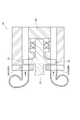
- FIG. 2 is an axial cross-sectional view of the two-phase flow turbine of FIG. 1.
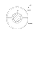
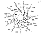
- FIG. 3 is a schematic diagram illustrating a first nozzle chamber and a second nozzle chamber in an axial vertical plane of FIG. 2.
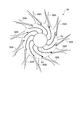
- FIG. 4 is a schematic view illustrating an example of a first turbine nozzle and a second turbine nozzle provided in a first nozzle chamber and a second nozzle chamber of FIG. 3.
- FIG. 3 is a schematic diagram showing a flow of a two-phase refrigerant in a tapered-divergent nozzle. It is a modification of FIG. It is a first modified example of FIG.
- FIG. 5 is a graph showing a correlation between a power generation efficiency of a generator and a parameter ratio of a two-phase flow turbine. It is a 2nd modification of FIG. 1 is a configuration diagram illustrating an entire configuration of a refrigeration cycle system according to a base technology.
- FIG. 10 is a configuration diagram showing an overall configuration of a refrigeration cycle system 10 'according to the base technology.
- the refrigeration cycle system 10 ' is an air conditioning system using a refrigeration cycle.
- a state in which the refrigeration cycle system 10 'is operated in a cooling cycle will be described, but the present invention is also applicable to a state in which it is operated in a heating cycle unless otherwise specified.
- the refrigeration cycle system 10 typically includes two refrigeration cycles (a first refrigeration cycle 10A and a second refrigeration cycle 10B) including a compression step, a condensation step, an expansion step, and an evaporation step.
- Each of the first refrigeration cycle 10A and the second refrigeration cycle 10B is configured by arranging a compressor, a condenser, an expansion valve, and an evaporator corresponding to each process on a circulation path through which a refrigerant flows, and is independent of each other. are doing.
- the first refrigeration cycle 10A includes a first compressor 14A, a first condenser 16A, a first upstream expansion valve 18A, a first gas-liquid separator 20A, a first downstream expansion valve 22A, One evaporator 24A is arranged in order.
- the first compressor 14A is a multi-stage type and includes a first low-pressure compressor 14A1 and a first high-pressure compressor 14A2 arranged in series along the circulation path 12A.
- the first low-pressure side compressor 14A1 and the first high-pressure side compressor 14A2 are coaxially connected to each other, and are configured to be drivable by the electric motor 26A.
- the high-temperature and high-pressure refrigerant discharged from the first compressor 14A is sent to the first condenser 16A and is condensed by heat exchange with the outside air.
- the refrigerant condensed in the first condenser 16A is decompressed by the first upstream expansion valve 18A, and then gas-liquid separated by the first gas-liquid separator 20A.
- a part of the gas phase component separated by the first gas-liquid separator 20A is recompressed by returning to the first high-pressure side compressor 14A2 via the return line 28A, and the rest is mixed with the first component together with the liquid phase component.
- the pressure is further reduced by the downstream expansion valve 22A.
- the refrigerant discharged from the first downstream expansion valve 22A is supplied to the first evaporator 24A.
- the first evaporator 24A cools the cooling water by exchanging heat between the refrigerant and the cooling water to generate cold heat due to the heat of vaporization of the refrigerant.
- the refrigerant that has completed the heat exchange in the first evaporator 24A is returned to the first compressor 14A, and the above cycle is repeated.
- the second refrigeration cycle 10B includes a second compressor 14B, a second condenser 16B, a second upstream expansion valve 18B, a second gas-liquid separator 20B, a second downstream expansion valve 22B, Two evaporators 24B are arranged in order.
- the second compressor 14B is a multi-stage type and includes a second low-pressure side compressor 14B1 and a second high-pressure side compressor 14B2 arranged in series along the circulation path 12B.
- the second low-pressure side compressor 14B1 and the second high-pressure side compressor 14B2 are coaxially connected to each other, and are configured to be drivable by the electric motor 26B.
- the high-temperature and high-pressure refrigerant discharged from the second compressor 14B is sent to the second condenser 16B and is condensed by heat exchange with the outside air.
- the refrigerant condensed in the second condenser 16B is decompressed by the second upstream expansion valve 18B, and then gas-liquid separated by the second gas-liquid separator 20B.
- Part of the gas phase component separated by the second gas-liquid separator 20B is recompressed by being returned to the second high-pressure side compressor 14B2 via the return line 28B, and the rest is mixed with the second component together with the liquid phase component.
- the pressure is further reduced by the downstream expansion valve 22B.
- the refrigerant discharged from the second downstream expansion valve 22B is supplied to the second evaporator 24B.
- the second evaporator 24B exchanges heat between the refrigerant and the cooling water to generate cold heat due to the heat of vaporization of the refrigerant, thereby cooling the cooling water.
- the refrigerant that has completed the heat exchange in the second evaporator 24B is returned to the second compressor 14B, and the above cycle is repeated.
- these two refrigeration cycles change the state at each point of the circulation paths 12A and 12B in accordance with the amount of cold heat supplied to the cooling water to be exchanged.
- the amount (pressure, temperature, etc.) is set.
- the first evaporator 24A and the second evaporator 24B are arranged in series with respect to the flow direction of the cooling water.
- the first evaporator 24A is arranged downstream of the second evaporator 24B. Have been.
- refrigerants handled in the first refrigeration cycle 10A and the second refrigeration cycle 10B are the same, and for example, R134a, R1233ZDE, R1234ZE, or the like is used.
- FIG. 1 is a configuration diagram showing an overall configuration of a refrigeration cycle system 10 according to at least one embodiment of the present invention.
- components corresponding to the above-described prerequisite technology are denoted by common reference numerals, and repeated description will be omitted unless otherwise specified.
- the first refrigeration cycle 10A and the second refrigeration cycle 12 included in the refrigeration cycle system 10 have the same configuration regarding the compression step, the condensation step, and the evaporation step as the above-described base technology, but differ in the configuration regarding the expansion step. That is, it is possible to improve the following embodiment by changing the configuration related to the expansion process in the base technology.
- the refrigeration cycle system 10 is a two-phase drivable by expanding the refrigerant discharged from the first condenser 16A constituting the first refrigeration cycle 10A and the second condenser 16B constituting the second refrigeration cycle 10B.
- a flow turbine 30 is provided.
- the two-phase flow turbine 30 uses a turbine blade 52 (see FIG. 2) by expansion energy generated when the two-phase flow refrigerant condensed in the first condenser 16A and the second condenser 16B is depressurized. ) Is driven.
- the turbine blade 52 generates electric energy by driving a generator 34 mechanically connected to the rotating shaft 32 via the rotating shaft 32.
- the two-phase flow turbine 30 recovers expansion energy generated in the expansion step as electric energy.
- the electric energy generated by the generator 34 may be stored in a power storage device such as a battery (not shown), or may be directly supplied to a load that consumes the electric energy.
- the refrigeration cycle system 10 at least a part of the expansion process in the first refrigeration cycle 10A and the second refrigeration cycle 10B is performed by the common two-phase flow turbine 30.
- the expansion energy generated during the expansion process in each of the first refrigeration cycle 10A and the second refrigeration cycle 10B can be recovered by the single two-phase flow turbine 30, and good system efficiency can be achieved.
- the two-phase flow turbine 30 is provided commonly to the first refrigeration cycle 10A and the second refrigeration cycle 10B, the two-phase flow turbine is provided for each of the first refrigeration cycle 10A and the second refrigeration cycle 10B. As compared with the above, good system efficiency can be obtained while suppressing costs.
- a gas-liquid separator 36 is provided downstream of the two-phase flow turbine 30.
- the first gas-liquid separator 20A and the second gas-liquid separator 20B are provided for the first refrigeration cycle 10A and the second refrigeration cycle 10B, but in the present embodiment, a common two-phase flow is used.
- the refrigerant discharged from the gas-liquid separator 36 passes through the first distribution channels 38A and 38B to the first evaporator 24A of the first refrigeration cycle 10A and the second evaporator 24B of the second refrigeration cycle 10B. Supplied respectively. Thereby, the refrigerant that has passed through the two-phase flow turbine 30 and the gas-liquid separator 36 common to the two refrigeration cycles is distributed to the two refrigeration cycles 10A and 10B via the first distribution channels 38A and 38B.
- a first expansion valve 40A provided between the two-phase flow turbine 30 and the first evaporator 24A, and between the two-phase flow turbine and the second evaporator 24B.
- the second expansion valve 40B provided. That is, the refrigerant discharged from the two-phase flow turbine 30 is further depressurized by the first expansion valve 40A and the second expansion valve 40B provided in the first distribution flow paths 38A and 38B, and then the first evaporator 24A and It is distributed to the second evaporator 24B.
- the first upstream expansion valve 18A and the second upstream expansion valve 18B are replaced with the two-phase flow turbine 30 in the above-described base technology (see FIG.
- the second downstream expansion valve 22B is left as a first expansion valve 40A and a second expansion valve 40B.
- expansion energy can be recovered in a region where the thermal head is large, and good system efficiency is achieved. it can.
- the distribution flow rate of the refrigerant to the first refrigeration cycle 10A and the second refrigeration cycle 10B by the first distribution channels 38A and 38B is, for example, the first expansion valve 40A and the second expansion valve provided on the first distribution channel 38. It may be implemented by adjusting the opening degree of each of the 40Bs. Thereby, the refrigerant whose energy has been recovered by the two-phase flow turbine 30 can be distributed at a flow rate suitable for the first refrigeration cycle 10A and the second refrigeration cycle 10B, so that better system efficiency can be achieved. In particular, even in the case where the prerequisite technology is modified to introduce the two-phase flow turbine 30, the opening of each of the first expansion valve 40A and the second expansion valve 40B is appropriately adjusted, so that each cycle can be started. Can be easily optimized. As a result, it is possible to easily perform a modification for introducing the two-phase flow turbine 30 to an existing system corresponding to the base technology.
- the refrigeration cycle system 10 also includes second distribution channels 42A and 42B configured to supply the gas phase component of the refrigerant separated by the gas-liquid separator 36 to the first compressor 14A and the second compressor 14B, respectively. Is provided.
- the refrigerant discharged from the two-phase flow turbine 30 after energy recovery contains a gas phase component and a liquid phase component, and these are separated by the gas-liquid separator 36.
- the gas phase component separated by the gas-liquid separator 36 is returned to the first compressor 14A and the second compressor 14B of each refrigeration cycle via the second distribution channels 42A and 42B. This makes it possible to recompress and condense gaseous phase components that do not contribute to the heat of vaporization in the first evaporator 24A and the second evaporator 24B, thereby further improving system efficiency.
- FIG. 2 is an axial cross-sectional view of the two-phase flow turbine 30 of FIG. 1
- FIG. 3 is a schematic diagram showing the first nozzle chamber 54A and the second nozzle chamber 54B in the axial vertical plane of FIG.
- circumferential direction when simply described as “circumferential direction”, “axial direction”, and “radial direction”, it means the circumferential direction, axial direction, and radial direction of the two-phase flow turbine 30, respectively.
- the two-phase flow turbine 30 is provided on a rotating shaft 50 extending along the axial direction, a plurality of turbine moving blades 52 arranged on the rotating shaft 50 along the circumferential direction, and an upstream side of the turbine moving blade 52.
- the refrigerant condensed from the first refrigeration cycle 10A (first condenser) and the second refrigeration cycle 10B (second condenser) is introduced into the two-phase flow turbine 30 as described above.
- the refrigerant introduced from the first refrigerant cycle 10A (the first condenser 16A) is supplied to the turbine blade 52 via the first nozzle chamber 54A.
- the refrigerant introduced from the second refrigerant cycle 10B (second condenser 16B) is supplied to the turbine blade 52 via the second nozzle chamber 54B.
- the first nozzle chamber 54A and the second nozzle chamber 54B are arranged at different positions along the circumferential direction around the rotation shaft 50 and are separated from each other. Thereby, even when there is a pressure difference between the refrigerant introduced from the first condenser 16A and the second condenser 16B to the two-phase flow turbine 30, the energy loss is suppressed to be small, and efficient power recovery is performed. be able to.
- the first nozzle chamber 54A includes at least one first turbine nozzle 58A configured to supply the refrigerant flowing from the first condenser 16A to the turbine bucket 52.
- the second nozzle chamber 54B includes at least one second turbine nozzle 58B configured to supply the refrigerant flowing from the second condenser 16B to the turbine bucket 52.
- FIG. 4 is a schematic view showing an example of the first turbine nozzle 58A and the second turbine nozzle 58B provided in the first nozzle chamber 54A and the second nozzle chamber 54B of FIG.
- first turbine nozzles 58A and a plurality of second turbine nozzles 58B are provided in the first nozzle chamber 54A and the second nozzle chamber 54B, respectively.
- the number of nozzles 58B may be the same or different.
- the first turbine nozzle 58A and the second turbine nozzle 58B are tapered-divergent nozzles.
- Such a tapered-divergent nozzle is, for example, a reamer nozzle formed by reaming.
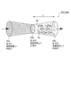
- FIG. 5 is a schematic diagram showing the flow of the two-phase refrigerant in the tapered-divergent nozzle.
- the tapered-divergent nozzle gradually decreases in inner diameter from a nozzle inlet portion 60a having an inner diameter D1 toward a throat portion 60b, has a minimum diameter D2 in the throat portion 60b, and has a throat portion 60b.
- the inner diameter gradually increases from the nozzle toward the nozzle outlet portion 60c having the inner diameter D3 (that is, D1> D2 and D2 ⁇ D3).
- the liquid refrigerant condensed from the first condenser 16A or the second condenser 16B is supplied to the nozzle inlet 60a.
- the refrigerant introduced into the nozzle inlet portion 60a is compressed toward the throat portion 60b, and is flushed in the throat portion 60b, so that the refrigerant becomes a two-phase flow of a gas phase and a liquid phase.
- the two-phase flow includes droplets 64 in gas 62. Since the weight of the droplet 64 is larger than that of the gas 62, the flow rate of the liquid 64 is smaller than the flow rate of the gas 62 (for example, the flow rate of the gas 62 is about 10 times the flow rate of the liquid 64).
- the liquid 64 is accelerated from the throat portion 60b to the nozzle outlet portion 60c by the high-speed gas 62 existing around.
- a two-phase flow including the accelerated droplets 64 is discharged toward the turbine blade.
- the two-phase flow discharged from the nozzle outlet 60c drives the turbine blade, and at this time, the accelerated droplet 64 mainly contained in the two-phase flow gives kinetic energy to the turbine blade. Become.
- the first nozzle chamber 54A and the second nozzle chamber 54B are supplied with refrigerants having different pressures from the first refrigeration cycle 10A and the second refrigeration cycle 10B.
- a refrigerant having a higher pressure than the second nozzle chamber 54B is supplied to 54A.
- the first turbine nozzle 58A and the second turbine nozzle 58B have different nozzle shapes according to the pressure. Specifically, as the pressure ratio P3 / P1 of the pressure P1 at the nozzle inlet 60a and the pressure P3 at the nozzle outlet 60c decreases, the first turbine nozzle 58A and the second turbine nozzle 58B flow through the throat portion 60b.
- the area expansion ratio ⁇ 3 / ⁇ 2 of the flow path area ⁇ 3 of the nozzle outlet 60c with respect to the area ⁇ 2 is formed to be smaller. This makes it possible to optimize the expansion of the working fluid in the nozzle on the low pressure cycle side and to accelerate the droplet acceleration in the nozzle, so that the turbine blade 52 can be driven more efficiently.
- the first turbine nozzle 58A and the second turbine nozzle 58B may be formed such that the length L from the throat portion 60b to the nozzle outlet 60c increases as the pressure P1 at the nozzle inlet 60a decreases.
- the droplet 64 generated at the throat portion 60b is a high-speed gas in the range of the length L between the throat portion 60b and the nozzle outlet portion 60c. Accelerated by 62. Therefore, when the inlet pressure of the turbine nozzle is small, the flow velocity of the liquid droplet (liquid phase component) included in the two-phase flow is relatively low, so that a large acceleration section is secured by designing the nozzle length to be large, The flow velocity at the nozzle outlet 60c can be increased.
- FIG. 6 is a modification of FIG. 4, but since the first turbine nozzle 58A is supplied with a refrigerant having a higher pressure than the second turbine nozzle 58B, in this modification, the length L2 of the second turbine nozzle 58B is , The first turbine nozzle 58A is set to be longer than the length L1. Thereby, the turbine bucket 52 can be driven more efficiently.
- FIG. 7 shows a first modification of FIG.
- a first flow rate control valve 60A and a second flow rate control valve 60B are provided at the nozzle inlet portion 60a of the first nozzle chamber 54A and the second nozzle chamber 54B, respectively.
- the first flow control valve 60A and the second flow control valve 60B are configured to control the flow rate of the refrigerant to the first nozzle chamber 54A and the second nozzle chamber 54B by adjusting the opening.
- the control of the first flow control valve 60A and the second flow control valve 60B may be performed manually (manually) by an operator, or automatically performed using an electronic arithmetic device such as a computer. Is also good.
- FIG. 8 is a graph showing a correlation between the power generation efficiency ⁇ of the generator and the parameter ratio U / C0 of the two-phase flow turbine 30.
- U is the rotational peripheral speed (m / s) of the two-phase flow turbine 30
- C0 indicates the theoretical speed at the turbine inlet (nozzle inlet) and the turbine outlet (moving blade outlet)
- C0 indicates the turbine pressure ratio.
- the turbine pressure ratio is defined by the pressure ratio at the turbine outlet to the turbine inlet.
- the pressure P1 (see FIG. 5) at the nozzle inlet 60a of the first nozzle chamber 54A or the second nozzle chamber 54B corresponds to the pressure at the turbine inlet.
- the pressure at the turbine outlet is strictly the outlet pressure of the turbine blade 52, in the present embodiment, it is simply assumed to be equivalent to the pressure P3 (see FIG. 5) at the nozzle outlet 60c. Therefore, the turbine pressure ratio is defined by the ratio P1 / P3 of the nozzle inlet pressure P1 to the nozzle outlet pressure P3. As shown in FIG. 8, the efficiency ⁇ has a maximum value at a specific parameter ratio U / C0, and the efficiency ⁇ tends to decrease when the operating state of the two-phase flow turbine 30 deviates from the optimum value. .
- the opening of the first flow control valve 60A and the second flow control valve 60B is controlled such that the parameter ratio U / C0 falls within a predetermined range including the maximum value of the efficiency ⁇ .
- the control range R of the parameter ratio U / C0 is indicated by hatching.
- FIG. 9 shows a second modification of FIG.
- the first flow control valve 60A and the second flow control valve 60B are provided for the first nozzle chamber 54A and the second nozzle chamber 54B, but in the second modified example. 9, may be provided for each of the first turbine nozzle 58A and the second turbine nozzle 58B. That is, the first flow control valve 60A and the second flow control valve 60B are individually provided for the first turbine nozzle 58A and the second turbine nozzle 58B included in the first nozzle chamber 54A and the second nozzle chamber 54B. Is also good.
- the first flow rate control valve 60A and the second flow rate control valve 60B are such that the parameter ratio U / C0 falls within a predetermined range including the maximum value of the efficiency ⁇ .
- the degree of opening is controlled.
- the first flow rate control valve 60A and the second flow rate control valve 60B are separately provided for the first turbine nozzle 58A and the second turbine nozzle 58B, so that the flow rate of the refrigerant for each turbine nozzle Can be finely adjusted. Therefore, compared to the first modification, the opening degree can be controlled with higher accuracy so that the parameter ratio U / C0 falls within a predetermined range including the maximum value of the efficiency ⁇ .
- the first flow control valve 60A and the second flow control valve 60B it is necessary to connect the first flow control valve 60A and the second flow control valve 60B to the first turbine nozzle 58A and the second turbine nozzle 58B.
- the second turbine nozzle 58B is easily realized by, for example, using a reamer nozzle that is easily mechanically connected.
- the first turbine nozzle 58A and the second turbine nozzle 58B can take other forms of the reamer nozzle.
- At least one embodiment of the present invention is applicable to a refrigeration cycle system capable of recovering expansion energy in an expansion stroke of a refrigeration cycle.
- Refrigeration cycle system 10A First refrigeration cycle 10B Second refrigeration cycle 12A, 12B Circulation path 14A First compressor 14B Second compressor 16A First condenser 16B Second condenser 24A First evaporator 24B Second evaporator 26A , 26B Electric motor 30 Two-phase flow turbine 34 Generator 36 Gas-liquid separator 38A, 38B First distribution channel 40A First expansion valve 40B Second expansion valve 42A, 42B Second distribution channel 52 Turbine blade 54A First nozzle Chamber 54B Second nozzle chamber 58A First turbine nozzle 58B Second turbine nozzle 60A First flow control valve 60B Second flow control valve 60a Nozzle inlet 60b Throat 60c Nozzle outlet
Landscapes
- Engineering & Computer Science (AREA)
- Mechanical Engineering (AREA)
- General Engineering & Computer Science (AREA)
- Physics & Mathematics (AREA)
- Thermal Sciences (AREA)
- Chemical & Material Sciences (AREA)
- Combustion & Propulsion (AREA)
- Engine Equipment That Uses Special Cycles (AREA)
Abstract
冷凍サイクルシステムは、第1冷凍サイクルの第1凝縮器、及び、第2冷凍サイクルの第2凝縮器から吐出された前記冷媒を膨張させることにより駆動可能な二相流タービンと、当該二相流タービンに機械的に連結された発電装置と、を備える。二相流タービンから吐出された冷媒は、第1分配流路を介して、第1圧縮機及び第2圧縮機にそれぞれ供給されるように構成される。
Description
本開示は、冷凍サイクルの膨張行程における膨張エネルギを回収可能な冷凍サイクルシステムに関する。
圧縮工程、凝縮工程、膨張工程及び蒸発工程を備える冷凍サイクルが知られている。この種の冷凍サイクルは、冷媒が流れる循環経路上に、各工程に対応する圧縮機、凝縮器、膨張弁及び蒸発器等の構成要素を配置することで構成され、例えば空調等に利用されている。冷凍サイクルを冷房として機能させる場合、圧縮工程で生成された高温の圧縮冷媒は凝縮工程で液化され、膨張行程で減圧された後、蒸発工程で気化されることにより冷熱が発生する。
典型的な冷凍サイクルでは、膨張工程は、例えば膨張弁のようなデバイスを用いて液化された冷媒の減圧を行われるが、特許文献1では、膨張弁に代えて、気液混合状態にある冷媒(二相流)によって駆動可能な二相流タービンを配置することにより、膨張工程で生じる膨張エネルギを回収することでシステム効率を向上させることが開示されている。また特許文献2には、二相流タービンの一例が開示されている。
冷凍サイクルを利用したシステムには、複数の冷凍サイクルを備えるものがある。この場合、特許文献1のように各冷凍サイクルの膨張工程を二相流タービンで実現しようとすると、冷凍サイクルの数だけ二相流タービンが必要となる。二相流タービンはコストが高いため、このようなシステムは採算性の面で不利であり、システム効率の向上にも限界がある。
本発明の少なくとも一実施形態は上述の事情に鑑みなされたものであり、低コストな構成を用いて冷凍サイクルにおける冷媒の膨張エネルギを回収することで良好なシステム効率を達成可能な冷凍サイクルシステムを提供することを目的とする。
(1)本発明の少なくとも一実施形態に係る冷凍サイクルシステムは上記課題を解決するために、
冷媒を圧縮する第1圧縮機、前記第1圧縮機から吐出された前記冷媒を凝縮する第1凝縮器、及び、前記第1凝縮器から吐出された前記冷媒を気化させる第1蒸発器を含む第1冷凍サイクルと、
前記冷媒を圧縮する第2圧縮機、前記第2圧縮機から吐出された前記冷媒を凝縮する第2凝縮器、及び、前記第2凝縮器から吐出された前記冷媒を気化させる第2蒸発器を含む第2冷凍サイクルと、
前記第1凝縮器及び前記第2凝縮器から吐出された前記冷媒を膨張させることにより駆動可能な二相流タービンと、
前記二相流タービンに機械的に連結された発電装置と、
前記二相流タービンから吐出された前記冷媒を前記第1圧縮機及び前記第2圧縮機にそれぞれ供給するように構成された第1分配流路と、
を備える。
冷媒を圧縮する第1圧縮機、前記第1圧縮機から吐出された前記冷媒を凝縮する第1凝縮器、及び、前記第1凝縮器から吐出された前記冷媒を気化させる第1蒸発器を含む第1冷凍サイクルと、
前記冷媒を圧縮する第2圧縮機、前記第2圧縮機から吐出された前記冷媒を凝縮する第2凝縮器、及び、前記第2凝縮器から吐出された前記冷媒を気化させる第2蒸発器を含む第2冷凍サイクルと、
前記第1凝縮器及び前記第2凝縮器から吐出された前記冷媒を膨張させることにより駆動可能な二相流タービンと、
前記二相流タービンに機械的に連結された発電装置と、
前記二相流タービンから吐出された前記冷媒を前記第1圧縮機及び前記第2圧縮機にそれぞれ供給するように構成された第1分配流路と、
を備える。
上記(1)の構成によれば、システムを構成する複数の冷凍サイクルにおける膨張行程の少なくとも一部が、共通の二相流タービンで実施される。これにより、各冷凍サイクルの膨張行程で生じる膨張エネルギを二相流タービンで回収し、良好なシステム効率を達成することができる。また二相流タービンは複数の冷凍サイクルに共通して設けられるため、冷凍サイクルの各々に対して二相流タービンをそれぞれ設ける場合に比べて、コストを抑えながら良好なシステム効率が得られる。
(2)幾つかの実施形態では上記(1)の構成において、
前記第1分配流路は、
前記二相流タービンと前記第1蒸発器との間に設けられた第1膨張弁と、
前記二相流タービンと前記第2蒸発器との間に設けられた第2膨張弁と、
を備える。
前記第1分配流路は、
前記二相流タービンと前記第1蒸発器との間に設けられた第1膨張弁と、
前記二相流タービンと前記第2蒸発器との間に設けられた第2膨張弁と、
を備える。
上記(2)の構成によれば、二相流タービンから吐出された冷媒が流れる第1分配流路には、第1冷凍サイクルを構成する第1膨張弁と、第2冷凍サイクルを構成する第2膨張弁とが設けられる。つまり、二相流タービンから吐出された冷媒は、第1分配流路に設けられた第1膨張弁及び第2膨張弁を介して第1冷凍サイクル及び第2冷凍サイクルに分配される。このような構成では、二相流タービンは第1膨張弁及び第膨張弁より上流側に設けられるため、熱落差が大きな領域で膨張エネルギの回収ができ、良好なシステム効率を達成できる。
(3)幾つかの実施形態では上記(2)の構成において、
前記第1膨張弁及び前記第2膨張弁は、各々の開度を調整することにより、前記二相流タービンから前記第1冷凍サイクル及び前記第2冷凍サイクルに対する前記冷媒の分配比率を調整可能に構成される。
前記第1膨張弁及び前記第2膨張弁は、各々の開度を調整することにより、前記二相流タービンから前記第1冷凍サイクル及び前記第2冷凍サイクルに対する前記冷媒の分配比率を調整可能に構成される。
上記(3)の構成によれば、二相流タービンより下流側に設けられる第1膨張弁及び第2膨張弁の開度をそれぞれ調整することにより、二相流タービンから第1冷凍サイクル及び第2冷凍サイクルに対する分配比率を自在に制御できる。これにより、二相流タービンにおけるエネルギ回収後の冷媒を、第1冷凍サイクル及び第2冷凍サイクルに適した流量で分配できるため、より良好なシステム効率を達成できる。
(4)幾つかの実施形態では上記(1)から(3)のいずれか一構成において、
前記二相流タービンの下流側に設けられた気液分離器と、
前記汽水分離器で分離された前記冷媒の気相成分を前記第1圧縮機及び前記第2圧縮機にそれぞれ供給するように構成された第2分配流路と、
を備える。
前記二相流タービンの下流側に設けられた気液分離器と、
前記汽水分離器で分離された前記冷媒の気相成分を前記第1圧縮機及び前記第2圧縮機にそれぞれ供給するように構成された第2分配流路と、
を備える。
上記(4)の構成によれば、二相流タービンから吐出されるエネルギ回収後の冷媒は気液分離器によって気相成分と液相成分に分離可能である。そして気液分離器で分離された気相成分は、第2分配流路を介して各冷凍サイクルの第1圧縮機及び第2圧縮機に戻される。これにより、気化熱に寄与しない気相成分を再圧縮・凝縮することが可能となり、システム効率をより向上できる。
(5)幾つかの実施形態では上記(1)から(4)のいずれか一構成において、
前記二相流タービンは、
前記第1凝縮器から流入する前記冷媒をタービン動翼に供給するように構成された少なくとも一つの第1タービンノズルを含む第1ノズル室と、
前記第2凝縮器から流入する前記冷媒を前記タービン動翼に供給するように構成された少なくとも一つの第2タービンノズルを含む第2ノズル室と、
を備え、
前記第1ノズル室及び前記第2ノズル室は互いに分離されている。
前記二相流タービンは、
前記第1凝縮器から流入する前記冷媒をタービン動翼に供給するように構成された少なくとも一つの第1タービンノズルを含む第1ノズル室と、
前記第2凝縮器から流入する前記冷媒を前記タービン動翼に供給するように構成された少なくとも一つの第2タービンノズルを含む第2ノズル室と、
を備え、
前記第1ノズル室及び前記第2ノズル室は互いに分離されている。
上記(5)の構成によれば、二相流タービンは、各冷凍サイクルの凝縮器から導入される二相流(気相成分及び液相成分の混合流)冷媒によって駆動される。この二相流タービンは、第1冷凍サイクルの第1凝縮器から流入する冷媒を導入してタービン動翼に供給する第1タービンノズルと、第2冷凍サイクルの第2凝縮器から流入する冷媒を導入してタービン動翼に供給する第2タービンノズルとを備える。第1タービンノズル及び第2タービンノズルは、それぞれ第1ノズル室及び第2ノズル室に配置されており、これらは互いに分離される。これにより、第1凝縮器及び第2凝縮器から二相流タービンに導入される冷媒間に圧力差がある場合であっても、エネルギロスを少なく抑え、効率のよい動力回収を行うことができる。
(6)幾つかの実施形態では上記(5)の構成において、
前記第1タービンノズル及び前記第2タービンノズルは、先細-末広型ノズルである。
前記第1タービンノズル及び前記第2タービンノズルは、先細-末広型ノズルである。
上記(6)の構成によれば、第1タービンノズル及び第2タービンノズルに先細-末広型ノズルが採用される。これにより、これらのタービンノズルを通過する二相流に含まれる液滴(液相成分)が気相成分によって効果的に加速され、タービン動翼をより効率的に駆動できる。
(7)幾つかの実施形態では上記(6)の構成において、
前記第1タービンノズル及び前記第2タービンノズルは、ノズル入口圧及びノズル出口圧の圧力比が小さくなるに従って、出口面積に対するスロート面積の面積拡大率が小さくなるように形成される。
前記第1タービンノズル及び前記第2タービンノズルは、ノズル入口圧及びノズル出口圧の圧力比が小さくなるに従って、出口面積に対するスロート面積の面積拡大率が小さくなるように形成される。
上記(7)の構成によれば、二相流タービンに用いられるタービンノズルの形状は、ノズル入口圧及びノズル出口圧の圧力比が小さくなるほど、スロート面積に対する出口面積の面積拡大率が小さくように設計される。これにより、低圧力サイクル側の作動流体のノズル内膨張を適正化し、ノズル内での液滴加速を促進できるため、タービン動翼をより効率的に駆動できる。
(8)幾つかの実施形態では上記(6)又は(7)の構成において、
前記第1タービンノズル及び前記第2タービンノズルは、ノズル入口圧が小さくなるに従って、スロート部からノズル出口部までの長さが大きくなるように形成される。
前記第1タービンノズル及び前記第2タービンノズルは、ノズル入口圧が小さくなるに従って、スロート部からノズル出口部までの長さが大きくなるように形成される。
上記(8)の構成によれば、二相流タービンに用いられるタービンノズルの長さは、タービンノズルのノズル入口圧に応じて設計される。例えばタービンノズルの入口圧が小さい場合には、二相流に含まれる液滴(液相成分)の流速が比較的遅いため、ノズル長さを大きく設計することで加速区間を多く確保し、ノズル出口における流速を高めることができる。これにより、タービン動翼をより効率的に駆動できる。
(9)幾つかの実施形態では上記(5)から(8)のいずれか一構成において、
前記第1ノズル室に対する前記冷媒の流量を調節するための第1流量調節弁と、
前記第2ノズル室に対する前記冷媒の流量を調節するための第2流量調節弁と、
を備え、
前記第1流量調節弁及び前記第2流量調節弁は、前記二相流タービンの回転周速Uと、ノズル入口圧及びタービン出口圧の理論速度C0との比U/C0が所定範囲内になるように制御される。
前記第1ノズル室に対する前記冷媒の流量を調節するための第1流量調節弁と、
前記第2ノズル室に対する前記冷媒の流量を調節するための第2流量調節弁と、
を備え、
前記第1流量調節弁及び前記第2流量調節弁は、前記二相流タービンの回転周速Uと、ノズル入口圧及びタービン出口圧の理論速度C0との比U/C0が所定範囲内になるように制御される。
上記(9)の構成によれば、第1ノズル室及び第2ノズル室に対する冷媒の流量は、第1流量調節弁及び第2流量調節弁によって、システム効率と相関を有する比U/C0が所定範囲内になるように制御される。これにより、例えば本システムが部分負荷運転のように運転状態が変化した場合であっても、所定のシステム効率が確保される。すなわち、部分負荷に対してロバストなシステム性能が得られる。
(10)幾つかの実施形態では上記(9)の構成において、
前記第1流量調節弁は、複数の前記第1タービンノズルを含む前記第1ノズル室に設けられ、
前記第2流量調節弁は、複数の前記第2タービンノズルを含む前記第2ノズル室に設けられる。
前記第1流量調節弁は、複数の前記第1タービンノズルを含む前記第1ノズル室に設けられ、
前記第2流量調節弁は、複数の前記第2タービンノズルを含む前記第2ノズル室に設けられる。
上記(10)の構成によれば、第1流量調節弁及び第2流量調節弁は第1ノズル室及び第2ノズル室に対してそれぞれ設けられるので、各ノズル室に設けられたタービンノズルにおける冷媒の流量をまとめて調節できる。
(11)幾つかの実施形態では上記(9)の構成において、
前記第1流量調節弁は、複数の前記第1タービンノズルの各々に設けられ、
前記第2流量調節弁は、複数の前記第2タービンノズルの各々に設けられる。
前記第1流量調節弁は、複数の前記第1タービンノズルの各々に設けられ、
前記第2流量調節弁は、複数の前記第2タービンノズルの各々に設けられる。
上記(11)の構成によれば、第1流量調節弁及び第2流量調節弁は、第1ノズル室及び第2ノズル室に含まれる各タービンノズルに対してそれぞれ設けられるので、タービンノズル単位で冷媒の流量をきめ細かく調節できる。
(12)幾つかの実施形態では上記(11)の構成において、
前記第1タービンノズル及び前記第2タービンノズルはリーマノズルである。
前記第1タービンノズル及び前記第2タービンノズルはリーマノズルである。
上記(12)の構成によれば、第1タービンノズル及び第2タービンノズルはリーマノズルとして構成されるため、タービンノズル単位で流量調節弁を容易に設けることができる。
本発明の少なくとも一実施形態によれば、低コストな構成を用いて冷凍サイクルにおける冷媒の膨張エネルギを回収することで良好なシステム効率を達成可能な冷凍サイクルシステムを提供できる。
以下、添付図面を参照して本発明の幾つかの実施形態について説明する。ただし、実施形態として記載されている又は図面に示されている構成部品の寸法、材質、形状、その相対的配置等は、本発明の範囲をこれに限定する趣旨ではなく、単なる説明例にすぎない。
<前提技術>
まず、本発明の少なくとも一実施形態に係る冷凍サイクルシステムの前提技術について説明する。図10は前提技術に係る冷凍サイクルシステム10´の全体構成を示す構成図である。冷凍サイクルシステム10´は、冷凍サイクルを利用した空調システムである。以下の説明では、冷凍サイクルシステム10´を冷房サイクルで運転している状態について述べるが、特段の記載がない限りにおいて暖房サイクルで運転している状態についても本発明を適用可能である。
まず、本発明の少なくとも一実施形態に係る冷凍サイクルシステムの前提技術について説明する。図10は前提技術に係る冷凍サイクルシステム10´の全体構成を示す構成図である。冷凍サイクルシステム10´は、冷凍サイクルを利用した空調システムである。以下の説明では、冷凍サイクルシステム10´を冷房サイクルで運転している状態について述べるが、特段の記載がない限りにおいて暖房サイクルで運転している状態についても本発明を適用可能である。
冷凍サイクルシステム10´は、典型的には、圧縮工程、凝縮工程、膨張工程及び蒸発工程からなる2系統の冷凍サイクル(第1冷凍サイクル10A及び第2冷凍サイクル10B)を含む。第1冷凍サイクル10A及び第2冷凍サイクル10Bの各々は、冷媒が流れる循環経路上に、各工程に対応する圧縮機、凝縮器、膨張弁及び蒸発器が配置されることで構成され、互いに独立している。
第1冷凍サイクル10Aは、循環経路12A上に、第1圧縮機14A、第1凝縮器16A、第1上流側膨張弁18A、第1気液分離器20A、第1下流側膨張弁22A、第1蒸発器24Aが順に配置される。第1圧縮機14Aは多段型であり、循環経路12Aに沿って直列的に配置された第1低圧側圧縮機14A1及び第1高圧側圧縮機14A2を含む。第1低圧側圧縮機14A1及び第1高圧側圧縮機14A2は互いに同軸上に連結されており、電動機26Aによって駆動可能に構成される。
第1圧縮機14Aから吐出される高温高圧の冷媒は第1凝縮器16Aに送られ、外気との熱交換により凝縮される。第1凝縮器16Aで凝縮された冷媒は、第1上流側膨張弁18Aによって減圧された後、第1気液分離器20Aによって気液分離される。第1気液分離器20Aによって分離された気相成分の一部は、戻しライン28Aを介して、第1高圧側圧縮機14A2に戻されることにより再圧縮され、残りは液相成分とともに第1下流側膨張弁22Aによって更に減圧される。
第1下流側膨張弁22Aから吐出された冷媒は、第1蒸発器24Aに供給される。第1蒸発器24Aでは、冷媒と冷却水とを熱交換することにより、冷媒の気化熱による冷熱を発生させることで、冷却水を冷却する。第1蒸発器24Aで熱交換を終えた冷媒は、第1圧縮機14Aに戻され、上記サイクルが繰り返される。
第2冷凍サイクル10Bは、循環経路12B上に、第2圧縮機14B、第2凝縮器16B、第2上流側膨張弁18B、第2気液分離器20B、第2下流側膨張弁22B、第2蒸発器24Bが順に配置される。第2圧縮機14Bは多段型であり、循環経路12Bに沿って直列的に配置された第2低圧側圧縮機14B1及び第2高圧側圧縮機14B2を含む。第2低圧側圧縮機14B1及び第2高圧側圧縮機14B2は互いに同軸上に連結されており、電動機26Bによって駆動可能に構成される。
第2圧縮機14Bから吐出される高温高圧の冷媒は第2凝縮器16Bに送られ、外気との熱交換により凝縮される。第2凝縮器16Bで凝縮された冷媒は、第2上流側膨張弁18Bによって減圧された後、第2気液分離器20Bによって気液分離される。第2気液分離器20Bによって分離された気相成分の一部は、戻しライン28Bを介して、第2高圧側圧縮機14B2に戻されることにより再圧縮され、残りは液相成分とともに第2下流側膨張弁22Bによって更に減圧される。
第2下流側膨張弁22Bから吐出された冷媒は、第2蒸発器24Bに供給される。第2蒸発器24Bでは、冷媒と冷却水とを熱交換することにより、冷媒の気化熱による冷熱を発生させることで、冷却水を冷却する。第2蒸発器24Bで熱交換を終えた冷媒は、第2圧縮機14Bに戻され、上記サイクルが繰り返される。
尚、これら2つの冷凍サイクル(第1冷凍サイクル10A及び第2冷凍サイクル10B)は、熱交換対象である冷却水に対して供給する冷熱量に応じて、循環経路12A及び12Bの各ポイントにおける状態量(圧力、温度など)が設定される。図10では、第1蒸発器24A及び第2蒸発器24Bは冷却水の流れ方向に対して直列的に配置されており、特に、第1蒸発器24Aは第2蒸発器24Bの下流側に配置されている。
尚、第1冷凍サイクル10A及び第2冷凍サイクル10Bで取り扱われる冷媒は互いに同じであり、例えばR134a、R1233ZDE、R1234ZEなどが用いられる。
ここで上述の冷凍サイクルシステム10´において、システム効率を向上させるために、第1冷凍サイクル10A及び第2冷凍サイクル10Bの膨張工程に対して、それぞれ二相流タービンを導入することが考えられる。この場合、冷凍サイクルシステム10´に含まれる冷凍サイクルの数(すなわち「2」)だけ二相流タービンが必要となる。二相流タービンはコストが高いため、このようなシステムは採算性の面で不利であり、システム効率の向上にも限界がある。このような課題は、以下に説明する実施形態によって解決可能である。
<冷凍サイクルシステム>
図1は本発明の少なくとも一実施形態に係る冷凍サイクルシステム10の全体構成を示す構成図である。尚、以下の説明では上述の前提技術に対応する構成には共通の符号を付すこととし、特段の記載がない限りにおいて、重複する説明は省略することとする。
図1は本発明の少なくとも一実施形態に係る冷凍サイクルシステム10の全体構成を示す構成図である。尚、以下の説明では上述の前提技術に対応する構成には共通の符号を付すこととし、特段の記載がない限りにおいて、重複する説明は省略することとする。
冷凍サイクルシステム10が備える第1冷凍サイクル10A及び第2冷凍サイクル12は、圧縮工程、凝縮工程及び蒸発工程に関する構成は、上述の前提技術と同じであるが、膨張工程に関する構成が異なっている。すなわち、前提技術について膨張工程に関する構成を変更することによって、以下の実施形態への改良も可能である。
冷凍サイクルシステム10は、第1冷凍サイクル10Aを構成する第1凝縮器16A、及び、第2冷凍サイクル10Bを構成する第2凝縮器16Bから吐出された冷媒を膨張させることにより駆動可能な二相流タービン30を備える。二相流タービン30は、第1凝縮器16A及び第2凝縮器16Bで凝縮された気液混合状態の二相流冷媒が減圧される際に生じる膨張エネルギによってタービン動翼52(図2を参照)が駆動される。タービン動翼52は回転軸32を介して、当該回転軸32に機械的に連結された発電機34を駆動することで、電気エネルギを発生させる。このように二相流タービン30は、膨張工程において生じる膨張エネルギを電気エネルギとして回収する。
尚、発電機34によって生成された電気エネルギは、不図示のバッテリ等の蓄電装置に蓄えられてもよいし、電気エネルギを消費する負荷に直接供給されてもよい。
このように冷凍サイクルシステム10では、第1冷凍サイクル10A及び第2冷凍サイクル10Bにおける膨張行程の少なくとも一部が、共通の二相流タービン30で実施される。これにより、第1冷凍サイクル10A及び第2冷凍サイクル10Bの各々における膨張行程で生じる膨張エネルギを単一の二相流タービン30で回収し、良好なシステム効率を達成することができる。また二相流タービン30は第1冷凍サイクル10A及び第2冷凍サイクル10Bに共通して設けられるため、第1冷凍サイクル10A及び第2冷凍サイクル10Bの各々に対して二相流タービンをそれぞれ設ける場合に比べて、コストを抑えながら良好なシステム効率が得られる。
二相流タービン30の下流側には、気液分離器36設けられる。前提技術では、第1冷凍サイクル10A及び第2冷凍サイクル10Bに対して第1気液分離器20A及び第2気液分離器20Bが設けられていたが、本実施形態では、共通の二相流タービン30の下流側に気液分離器36を設けることで、システム構成の複雑化及び大型化を抑制できている。
気液分離器36から吐出される冷媒は、第1分配流路38A,38Bを介して、第1冷凍サイクル10Aの第1蒸発器24A、及び、第2冷凍サイクル10Bの第2蒸発器24Bにそれぞれ供給される。これにより、2つの冷凍サイクルに共通する二相流タービン30及び気液分離器36を通過した冷媒は、第1分配流路38A,38Bを介して2つの冷凍サイクル10A,10Bに分配される。
第1分配流路38A,38Bには、二相流タービン30と第1蒸発器24Aとの間に設けられた第1膨張弁40Aと、二相流タービンと第2蒸発器24Bとの間に設けられた第2膨張弁40Bと、がそれぞれ設けられる。つまり、二相流タービン30から吐出された冷媒は、第1分配流路38A,38Bに設けられた第1膨張弁40A及び第2膨張弁40Bによって更に減圧された後に、第1蒸発器24A及び第2蒸発器24Bに分配される。言い換えれば、本実施形態は前述の前提技術(図10を参照)において第1上流側膨張弁18A及び第2上流側膨張弁18Bを二相流タービン30に置換し、第1下流側膨張弁22A及び第2下流側膨張弁22Bは、第1膨張弁40A及び第2膨張弁40Bとして残している。このような構成では、二相流タービン30は第1膨張弁40A及び第2膨張弁40Bより上流側に設けられるため、熱落差が大きな領域で膨張エネルギの回収ができ、良好なシステム効率を達成できる。
第1分配流路38A,38Bによる第1冷凍サイクル10A及び第2冷凍サイクル10Bに対する冷媒の分配流量は、例えば、第1分配流路38上に設けられた第1膨張弁40A及び第2膨張弁40Bの開度をそれぞれ調節することにより実施されてもよい。これにより、二相流タービン30によってエネルギ回収がなされた冷媒を、第1冷凍サイクル10A及び第2冷凍サイクル10Bに適した流量で分配できるため、より良好なシステム効率を達成できる。特に、前提技術に対して二相流タービン30を導入する改修を施した場合であっても、第1膨張弁40A及び第2膨張弁40Bの開度を適切に調整することで、各サイクルへの分配比率を容易に最適化できる。これにより、前提技術に対応する既存システムに対して二相流タービン30を導入する改修を容易に行うことが可能となる。
また冷凍サイクルシステム10は、気液分離器36で分離された冷媒の気相成分を第1圧縮機14A及び第2圧縮機14Bにそれぞれ供給するように構成された第2分配流路42A,42Bを備える。二相流タービン30から吐出されるエネルギ回収後の冷媒は気相成分と液相成分が含まれ、これらは気液分離器36によって分離される。そして気液分離器36で分離された気相成分は、第2分配流路42A,42Bを介して各冷凍サイクルの第1圧縮機14A及び第2圧縮機14Bに戻される。これにより、第1蒸発器24A及び第2蒸発器24Bにおいて気化熱に寄与しない気相成分を再圧縮・凝縮することが可能となり、システム効率をより向上できる。
<二相流タービン>
続いて冷凍サイクルシステム10で用いられる二相流タービン30の具体的構成について説明する。図2は図1の二相流タービン30の軸方向断面図であり、図3は図2の軸方向垂直面における第1ノズル室54A及び第2ノズル室54Bを示す模式図である。
尚、以下で単に「周方向」、「軸方向」、「径方向」と記載する場合は、それぞれ二相流タービン30の周方向、軸方向、径方向を意味するものとする。
続いて冷凍サイクルシステム10で用いられる二相流タービン30の具体的構成について説明する。図2は図1の二相流タービン30の軸方向断面図であり、図3は図2の軸方向垂直面における第1ノズル室54A及び第2ノズル室54Bを示す模式図である。
尚、以下で単に「周方向」、「軸方向」、「径方向」と記載する場合は、それぞれ二相流タービン30の周方向、軸方向、径方向を意味するものとする。
二相流タービン30は、軸方向に沿って延びる回転軸50と、回転軸50上に周方向に沿って配列された複数のタービン動翼52と、タービン動翼52の上流側に設けられた第1ノズル室54A及び第2ノズル室54Bと、タービン動翼52の下流側に設けられたタービンディフューザ56と、を備える。
二相流タービン30には、上述したように、第1冷凍サイクル10A(第1凝縮器)及び第2冷凍サイクル10B(第2凝縮器)から、それぞれ凝縮された冷媒が導入される。第1冷媒サイクル10A(第1凝縮器16A)から導入される冷媒は、第1ノズル室54Aを介して、タービン動翼52に供給される。第2冷媒サイクル10B(第2凝縮器16B)から導入される冷媒は、第2ノズル室54Bを介して、タービン動翼52に供給される。
図3に示されるように、第1ノズル室54A及び第2ノズル室54Bは、回転軸50の周囲に周方向に沿った異なる位置に配置されており、互いに分離されている。これにより、第1凝縮器16A及び第2凝縮器16Bから二相流タービン30に導入される冷媒間に圧力差がある場合であっても、エネルギロスを少なく抑え、効率のよい動力回収を行うことができる。
第1ノズル室54Aは、第1凝縮器16Aから流入する冷媒をタービン動翼52に供給するように構成された少なくとも一つの第1タービンノズル58Aを含む。第2ノズル室54Bは、第2凝縮器16Bから流入する冷媒をタービン動翼52に供給するように構成された少なくとも一つの第2タービンノズル58Bを含む。
ここで図4は図3の第1ノズル室54A及び第2ノズル室54Bに設けられた第1タービンノズル58A及び第2タービンノズル58Bの一例を示す模式図である。この実施形態では、第1ノズル室54A及び第2ノズル室54Bには、それぞれ複数の第1タービンノズル58A及び第2タービンノズル58Bが設けられる場合について述べるが、第1タービンノズル58A及び第2タービンノズル58Bの数は同じであってもよいし、異なっていてもよい。
第1タービンノズル58A及び第2タービンノズル58Bは、先細-末広型ノズルである。このような先細-末広型ノズルは、例えばリーマ加工によって形成されるリーマノズルである。図5は先細-末広型ノズルにおける二相流冷媒の流れを示す模式図である。図5に示されるように、先細-末広型ノズルは、内径D1を有するノズル入口部60aからスロート部60bに向けて内径が次第に減少し、スロート部60bにおいて最小径D2を有するとともに、スロート部60bから内径D3を有するノズル出口部60cに向けて内径が次第に増加するように構成される(すなわち、D1>D2且つD2<D3)。
ノズル入口部60aには第1凝縮器16A又は第2凝縮器16Bから凝縮された液相の冷媒が供給される。ノズル入口部60aに導入された冷媒は、スロート部60bに向かうに従って圧縮され、スロート部60bにおいてフラッシュされることにより、気相と液相との二相流となる。二相流は、気体62中に液滴64を含む。液滴64は気体62に比べて重量が大きいため、液体64の流速は気体62の流速に比べて小さくなる(例えば気体62の流速は、液体64の流速の約10倍である)。液体64は、スロート部60bからノズル出口部60cにかけて、周囲に存在する高速な気体62によって加速する。ノズル出口部60cでは、加速された液滴64を含む二相流がタービン動翼に向けて吐出される。ノズル出口部60cから吐出された二相流は、タービン動翼を駆動するが、このとき主に二相流に含まれる加速された液滴64がタービン動翼に対して運動エネルギを与えることとなる。
本実施形態では、第1ノズル室54A及び第2ノズル室54Bには、上述したように、第1冷凍サイクル10A及び第2冷凍サイクル10Bから異なる圧力の冷媒が供給され、特に、第1ノズル室54Aには第2ノズル室54Bより高圧な冷媒が供給される。第1タービンノズル58A及び第2タービンノズル58Bは、圧力に応じて異なるノズル形状を有する。具体的には、第1タービンノズル58A及び第2タービンノズル58Bは、ノズル入口部60aにおける圧力P1及びノズル出口部60cにおける圧力P3の圧力比P3/P1が小さくなるに従って、スロート部60bの流路面積ρ2に対するノズル出口部60cの流路面積ρ3の面積拡大率ρ3/ρ2が小さくなるように形成される。これにより、低圧力サイクル側の作動流体のノズル内膨張を適正化し、ノズル内での液滴加速を促進できるため、タービン動翼52をより効率的に駆動できる。
また第1タービンノズル58A及び第2タービンノズル58Bは、ノズル入口部60aにおける圧力P1が小さくなるに従って、スロート部60bからノズル出口部60cまでの長さLが大きくなるように形成されてもよい。
図5を参照して上述したように、先細-末広型ノズルではスロート部60bで生じた液滴64は、スロート部60bとノズル出口部60cとの間である長さLの範囲において高速な気体62によって加速される。そのため、タービンノズルの入口圧が小さい場合には、二相流に含まれる液滴(液相成分)の流速が比較的遅いため、ノズル長さを大きく設計することで加速区間を大きく確保し、ノズル出口部60cにおける流速を高めることができる。
図6は図4の変形例であるが、第1タービンノズル58Aには第2タービンノズル58Bより高い圧力の冷媒が供給されるため、この変形例では、第2タービンノズル58Bの長さL2は、第1タービンノズル58Aの長さL1より大きく設定されている。これにより、タービン動翼52をより効率的に駆動できる。
<第1変形例>
図7は図4の第1変形例である。本変形例では、第1ノズル室54A及び第2ノズル室54Bのノズル入口部60aに、第1流量調節弁60A及び第2流量調節弁60Bがそれぞれ設けられている。第1流量調節弁60A及び第2流量調節弁60Bは、開度を調節することにより第1ノズル室54A及び第2ノズル室54Bに対する冷媒の流量を制御可能に構成されている。
尚、第1流量調節弁60A及び第2流量調節弁60Bの制御は、オペレータによる手動(マニュアル)によって実施されてもよいし、コンピュータのような電子演算装置を利用して自動的に実施されてもよい。
図7は図4の第1変形例である。本変形例では、第1ノズル室54A及び第2ノズル室54Bのノズル入口部60aに、第1流量調節弁60A及び第2流量調節弁60Bがそれぞれ設けられている。第1流量調節弁60A及び第2流量調節弁60Bは、開度を調節することにより第1ノズル室54A及び第2ノズル室54Bに対する冷媒の流量を制御可能に構成されている。
尚、第1流量調節弁60A及び第2流量調節弁60Bの制御は、オペレータによる手動(マニュアル)によって実施されてもよいし、コンピュータのような電子演算装置を利用して自動的に実施されてもよい。
ここで図8は、二相流タービン30のパラメータ比U/C0に対する発電機の発電効率ηの相関を示すグラフである。ここでUは二相流タービン30の回転周速(m/s)であり、C0はタービン入口(ノズル入口)とタービン出口(動翼出口)における理論速度を示し、このC0はタービン圧力比に相関する。尚、タービン圧力比は、タービン入口部に対するタービン出口部における圧力比によって定義される。本実施形態では、第1ノズル室54A又は第2ノズル室54Bのノズル入口部60aにおける圧力P1(図5を参照)がタービン入口部の圧力に相当する。またタービン出口部における圧力は、厳密にはタービン動翼52の出口圧力であるが、本実施形態では簡略的に、ノズル出口部60cにおける圧力P3(図5を参照)と同等であるとみなす。そのため、タービン圧力比は、ノズル出口圧P3に対するノズル入口圧P1の比P1/P3によって規定される。図8に示されるように、効率ηは特定のパラメータ比U/C0で最大値を有し、二相流タービン30の運転状態が最適値から乖離すると効率ηが低下する傾向が示されている。
本変形例では、第1流量調節弁60A及び第2流量調節弁60Bは、パラメータ比U/C0が効率ηの最大値を含む所定範囲内になるように開度が制御される。図8の例では、パラメータ比U/C0の制御範囲Rがハッチングで示されている。これにより、例えば冷凍サイクルシステム10が部分負荷運転のように運転状態が変化した場合であっても、所定のシステム効率が確保される。すなわち、部分負荷に対してロバストなシステム性能が得られる。
<変形例2>
図9は図4の第2変形例である。第1変形例(図7)では、第1流量調節弁60A及び第2流量調節弁60Bは、第1ノズル室54A及び第2ノズル室54Bに対して設けられているが、第2変形例では、図9に示されるように、第1タービンノズル58A及び第2タービンノズル58Bの各々に対して設けられていてもよい。すなわち、第1ノズル室54A及び第2ノズル室54Bに含まれる第1タービンノズル58A及び第2タービンノズル58Bに対して、第1流量調節弁60A及び第2流量調節弁60Bが個別に設けられてもよい。
図9は図4の第2変形例である。第1変形例(図7)では、第1流量調節弁60A及び第2流量調節弁60Bは、第1ノズル室54A及び第2ノズル室54Bに対して設けられているが、第2変形例では、図9に示されるように、第1タービンノズル58A及び第2タービンノズル58Bの各々に対して設けられていてもよい。すなわち、第1ノズル室54A及び第2ノズル室54Bに含まれる第1タービンノズル58A及び第2タービンノズル58Bに対して、第1流量調節弁60A及び第2流量調節弁60Bが個別に設けられてもよい。
第2変形例においても上述の第1変形例と同様に、第1流量調節弁60A及び第2流量調節弁60Bは、パラメータ比U/C0が効率ηの最大値を含む所定範囲内になるように開度が制御される。第2変形例では、第1タービンノズル58A及び第2タービンノズル58Bに対して、第1流量調節弁60A及び第2流量調節弁60Bが個別に設けられているため、タービンノズル単位で冷媒の流量をきめ細かく調節できる。そのため、第1変形例に比べて、より精度よくパラメータ比U/C0が効率ηの最大値を含む所定範囲内になるように開度制御可能である。
尚、第2変形例では、第1タービンノズル58A及び第2タービンノズル58Bに対して、第1流量調節弁60A及び第2流量調節弁60Bを接続する必要があるため、第1タービンノズル58A及び第2タービンノズル58Bは、例えば機械的に接続が容易なリーマノズルとすることで実現が容易となる。もちろん第1タービンノズル58A及び第2タービンノズル58Bはリーマノズルの他の態様も取り得ることは自明である。
以上説明したように本発明の少なくとも一実施形態によれば、低コストな構成を用いて冷凍サイクルにおける冷媒の膨張エネルギを回収することで良好なシステム効率を達成可能な冷凍サイクルシステムを提供できる。
本発明の少なくとも一実施形態は、冷凍サイクルの膨張行程における膨張エネルギを回収可能な冷凍サイクルシステムに利用可能である。
10 冷凍サイクルシステム
10A 第1冷凍サイクル
10B 第2冷凍サイクル
12A,12B 循環経路
14A 第1圧縮機
14B 第2圧縮機
16A 第1凝縮器
16B 第2凝縮器
24A 第1蒸発器
24B 第2蒸発器
26A,26B 電動機
30 二相流タービン
34 発電機
36 気液分離器
38A,38B 第1分配流路
40A 第1膨張弁
40B 第2膨張弁
42A,42B 第2分配流路
52 タービン動翼
54A 第1ノズル室
54B 第2ノズル室
58A 第1タービンノズル
58B 第2タービンノズル
60A 第1流量調節弁
60B 第2流量調節弁
60a ノズル入口部
60b スロート部
60c ノズル出口部
10A 第1冷凍サイクル
10B 第2冷凍サイクル
12A,12B 循環経路
14A 第1圧縮機
14B 第2圧縮機
16A 第1凝縮器
16B 第2凝縮器
24A 第1蒸発器
24B 第2蒸発器
26A,26B 電動機
30 二相流タービン
34 発電機
36 気液分離器
38A,38B 第1分配流路
40A 第1膨張弁
40B 第2膨張弁
42A,42B 第2分配流路
52 タービン動翼
54A 第1ノズル室
54B 第2ノズル室
58A 第1タービンノズル
58B 第2タービンノズル
60A 第1流量調節弁
60B 第2流量調節弁
60a ノズル入口部
60b スロート部
60c ノズル出口部
Claims (12)
- 冷媒を圧縮する第1圧縮機、前記第1圧縮機から吐出された前記冷媒を凝縮する第1凝縮器、及び、前記第1凝縮器から吐出された前記冷媒を気化させる第1蒸発器を含む第1冷凍サイクルと、
前記冷媒を圧縮する第2圧縮機、前記第2圧縮機から吐出された前記冷媒を凝縮する第2凝縮器、及び、前記第2凝縮器から吐出された前記冷媒を気化させる第2蒸発器を含む第2冷凍サイクルと、
前記第1凝縮器及び前記第2凝縮器から吐出された前記冷媒を膨張させることにより駆動可能な二相流タービンと、
前記二相流タービンに機械的に連結された発電装置と、
前記二相流タービンから吐出された前記冷媒を前記第1圧縮機及び前記第2圧縮機にそれぞれ供給するように構成された第1分配流路と、
を備える、冷凍サイクルシステム。 - 前記第1分配流路は、
前記二相流タービンと前記第1蒸発器との間に設けられた第1膨張弁と、
前記二相流タービンと前記第2蒸発器との間に設けられた第2膨張弁と、
を備える、請求項1に記載の冷凍サイクルシステム。 - 前記第1膨張弁及び前記第2膨張弁は、各々の開度を調整することにより、前記二相流タービンから前記第1冷凍サイクル及び前記第2冷凍サイクルに対する前記冷媒の分配比率を調整可能に構成される、請求項2に記載の冷凍サイクルシステム。
- 前記二相流タービンの下流側に設けられた気液分離器と、
前記汽水分離器で分離された前記冷媒の気相成分を前記第1圧縮機及び前記第2圧縮機にそれぞれ供給するように構成された第2分配流路と、
を備える、請求項1から3のいずれか一項に記載の冷凍サイクルシステム。 - 前記二相流タービンは、
前記第1凝縮器から流入する前記冷媒をタービン動翼に供給するように構成された少なくとも一つの第1タービンノズルを含む第1ノズル室と、
前記第2凝縮器から流入する前記冷媒を前記タービン動翼に供給するように構成された少なくとも一つの第2タービンノズルを含む第2ノズル室と、
を備え、
前記第1ノズル室及び前記第2ノズル室は互いに分離されている、請求項1から4のいずれか一項に記載の冷凍サイクルシステム。 - 前記第1タービンノズル及び前記第2タービンノズルは、先細-末広型ノズルである、請求項5に記載の冷凍サイクルシステム。
- 前記第1タービンノズル及び前記第2タービンノズルは、ノズル入口圧及びノズル出口圧の圧力比が小さくなるに従って、スロート面積に対する出口面積の面積拡大率が小さくなるように形成される、請求項6に記載の冷凍サイクルシステム。
- 前記第1タービンノズル及び前記第2タービンノズルは、ノズル入口圧が小さくなるに従って、スロート部からノズル出口部までの長さが大きくなるように形成される、請求項6又は7に記載の冷凍サイクルシステム。
- 前記第1ノズル室に対する前記冷媒の流量を調節するための第1流量調節弁と、
前記第2ノズル室に対する前記冷媒の流量を調節するための第2流量調節弁と、
を備え、
前記第1流量調節弁及び前記第2流量調節弁は、前記二相流タービンの回転周速Uと、ノズル入口圧及びタービン出口圧の理論速度C0との比U/C0が所定範囲内になるように制御される、請求項5から8のいずれか一項に記載の冷凍サイクルシステム。 - 前記第1流量調節弁は、複数の前記第1タービンノズルを含む前記第1ノズル室に設けられ、
前記第2流量調節弁は、複数の前記第2タービンノズルを含む前記第2ノズル室に設けられる、請求項9に記載の冷凍サイクルシステム。 - 前記第1流量調節弁は、複数の前記第1タービンノズルの各々に設けられ、
前記第2流量調節弁は、複数の前記第2タービンノズルの各々に設けられる、請求項9に記載の冷凍サイクルシステム。 - 前記第1タービンノズル及び前記第2タービンノズルはリーマノズルである、請求項11に記載の冷凍サイクルシステム。
Applications Claiming Priority (2)
| Application Number | Priority Date | Filing Date | Title |
|---|---|---|---|
| JP2018151766A JP7094824B2 (ja) | 2018-08-10 | 2018-08-10 | 冷凍サイクルシステム |
| JP2018-151766 | 2018-08-10 |
Publications (1)
| Publication Number | Publication Date |
|---|---|
| WO2020031725A1 true WO2020031725A1 (ja) | 2020-02-13 |
Family
ID=69414100
Family Applications (1)
| Application Number | Title | Priority Date | Filing Date |
|---|---|---|---|
| PCT/JP2019/029247 Ceased WO2020031725A1 (ja) | 2018-08-10 | 2019-07-25 | 冷凍サイクルシステム |
Country Status (2)
| Country | Link |
|---|---|
| JP (1) | JP7094824B2 (ja) |
| WO (1) | WO2020031725A1 (ja) |
Citations (2)
| Publication number | Priority date | Publication date | Assignee | Title |
|---|---|---|---|---|
| JPS5410102U (ja) * | 1977-06-24 | 1979-01-23 | ||
| JP2002168101A (ja) * | 2000-11-30 | 2002-06-14 | Toshiba Corp | 複合エネルギーシステム |
Family Cites Families (4)
| Publication number | Priority date | Publication date | Assignee | Title |
|---|---|---|---|---|
| FI791079A7 (fi) * | 1979-04-02 | 1981-01-01 | Valmet Oy | Lämpöpumpun hyväksikäyttöön perustuva menetelmä lämmön talteenotossa. |
| JPS6198954U (ja) * | 1985-12-04 | 1986-06-25 | ||
| US5467613A (en) * | 1994-04-05 | 1995-11-21 | Carrier Corporation | Two phase flow turbine |
| EP2889558B1 (en) * | 2013-12-30 | 2019-05-08 | Rolls-Royce Corporation | Cooling system with expander and ejector |
-
2018
- 2018-08-10 JP JP2018151766A patent/JP7094824B2/ja active Active
-
2019
- 2019-07-25 WO PCT/JP2019/029247 patent/WO2020031725A1/ja not_active Ceased
Patent Citations (2)
| Publication number | Priority date | Publication date | Assignee | Title |
|---|---|---|---|---|
| JPS5410102U (ja) * | 1977-06-24 | 1979-01-23 | ||
| JP2002168101A (ja) * | 2000-11-30 | 2002-06-14 | Toshiba Corp | 複合エネルギーシステム |
Also Published As
| Publication number | Publication date |
|---|---|
| JP2020026919A (ja) | 2020-02-20 |
| JP7094824B2 (ja) | 2022-07-04 |
Similar Documents
| Publication | Publication Date | Title |
|---|---|---|
| KR101441765B1 (ko) | 열기 및 냉기 관리용 제트 펌프 시스템, 장치, 배열체 및 사용방법 | |
| JP2002327700A (ja) | 遠心圧縮機および冷凍機 | |
| KR20020029597A (ko) | 다단 압축 냉각기 | |
| JP2011043130A (ja) | 遠心圧縮機及び冷凍装置 | |
| JPH0842930A (ja) | 単流体冷却装置 | |
| WO2013140990A1 (ja) | 冷凍サイクル及び冷凍ショーケース | |
| US11465756B2 (en) | Bootstrap air cycle with vapor power turbine | |
| US7730712B2 (en) | System and method for use in a combined cycle or rankine cycle power plant using an air-cooled steam condenser | |
| JPWO2008139528A1 (ja) | 冷却サイクル系統、天然ガス液化設備、冷却サイクル系統の運転方法及び改造方法 | |
| JP2005345083A (ja) | 冷凍空調装置の液側エネルギ回収システム | |
| US20160363351A1 (en) | Heat exchange apparatus and heat pump apparatus | |
| JP5136096B2 (ja) | ターボ圧縮機及び冷凍機 | |
| JP7094824B2 (ja) | 冷凍サイクルシステム | |
| JP4976426B2 (ja) | 冷凍サイクル系統、天然ガス液化設備、及び冷凍サイクル系統の改造方法 | |
| JP2004300928A (ja) | 多段圧縮機、ヒートポンプ、並びに熱利用装置 | |
| JP7607795B2 (ja) | ガスタービンプラント、その運転方法、及びその改造方法 | |
| JP6987598B2 (ja) | 冷凍サイクルの制御装置、熱源装置、及びその制御方法 | |
| WO2020113332A1 (en) | System and method of mechanical compression refrigeration based on two-phase ejector | |
| US20070157659A1 (en) | Multi-stage refrigerant turbine | |
| WO2023163614A1 (ru) | Установка генерации тепла и холода | |
| JP2013170808A (ja) | 冷凍機 | |
| WO2023095362A1 (ja) | ガスタービンプラント、その運転方法、及びその改造方法 | |
| US7805942B2 (en) | Thermodynamic cycle with power unit and venturi and a method of producing a useful effect therewith | |
| JP7168376B2 (ja) | 二相流タービン動翼、二相流タービン、及び、冷凍サイクルシステム | |
| JP2007212071A (ja) | 冷凍サイクル装置 |
Legal Events
| Date | Code | Title | Description |
|---|---|---|---|
| 121 | Ep: the epo has been informed by wipo that ep was designated in this application |
Ref document number: 19848083 Country of ref document: EP Kind code of ref document: A1 |
|
| NENP | Non-entry into the national phase |
Ref country code: DE |
|
| 122 | Ep: pct application non-entry in european phase |
Ref document number: 19848083 Country of ref document: EP Kind code of ref document: A1 |