WO2020031645A1 - Dispositif de communication, procédé de communication, et support d'enregistrement - Google Patents
Dispositif de communication, procédé de communication, et support d'enregistrement Download PDFInfo
- Publication number
- WO2020031645A1 WO2020031645A1 PCT/JP2019/028173 JP2019028173W WO2020031645A1 WO 2020031645 A1 WO2020031645 A1 WO 2020031645A1 JP 2019028173 W JP2019028173 W JP 2019028173W WO 2020031645 A1 WO2020031645 A1 WO 2020031645A1
- Authority
- WO
- WIPO (PCT)
- Prior art keywords
- beam group
- information
- commonality
- communication device
- measurement result
- Prior art date
Links
Images


Classifications
-
- H—ELECTRICITY
- H04—ELECTRIC COMMUNICATION TECHNIQUE
- H04W—WIRELESS COMMUNICATION NETWORKS
- H04W16/00—Network planning, e.g. coverage or traffic planning tools; Network deployment, e.g. resource partitioning or cells structures
- H04W16/24—Cell structures
- H04W16/28—Cell structures using beam steering
-
- H—ELECTRICITY
- H04—ELECTRIC COMMUNICATION TECHNIQUE
- H04B—TRANSMISSION
- H04B7/00—Radio transmission systems, i.e. using radiation field
- H04B7/02—Diversity systems; Multi-antenna system, i.e. transmission or reception using multiple antennas
- H04B7/04—Diversity systems; Multi-antenna system, i.e. transmission or reception using multiple antennas using two or more spaced independent antennas
- H04B7/06—Diversity systems; Multi-antenna system, i.e. transmission or reception using multiple antennas using two or more spaced independent antennas at the transmitting station
- H04B7/0686—Hybrid systems, i.e. switching and simultaneous transmission
- H04B7/0695—Hybrid systems, i.e. switching and simultaneous transmission using beam selection
-
- H—ELECTRICITY
- H04—ELECTRIC COMMUNICATION TECHNIQUE
- H04B—TRANSMISSION
- H04B7/00—Radio transmission systems, i.e. using radiation field
- H04B7/02—Diversity systems; Multi-antenna system, i.e. transmission or reception using multiple antennas
- H04B7/04—Diversity systems; Multi-antenna system, i.e. transmission or reception using multiple antennas using two or more spaced independent antennas
- H04B7/06—Diversity systems; Multi-antenna system, i.e. transmission or reception using multiple antennas using two or more spaced independent antennas at the transmitting station
- H04B7/0686—Hybrid systems, i.e. switching and simultaneous transmission
- H04B7/0691—Hybrid systems, i.e. switching and simultaneous transmission using subgroups of transmit antennas
-
- H—ELECTRICITY
- H04—ELECTRIC COMMUNICATION TECHNIQUE
- H04W—WIRELESS COMMUNICATION NETWORKS
- H04W24/00—Supervisory, monitoring or testing arrangements
- H04W24/10—Scheduling measurement reports ; Arrangements for measurement reports
-
- H—ELECTRICITY
- H04—ELECTRIC COMMUNICATION TECHNIQUE
- H04W—WIRELESS COMMUNICATION NETWORKS
- H04W68/00—User notification, e.g. alerting and paging, for incoming communication, change of service or the like
- H04W68/005—Transmission of information for alerting of incoming communication
Definitions
- the present disclosure relates to a communication device, a communication method, and a recording medium.
- LTE Long Term Evolution
- LTE-A Long Term Evolution
- LTE-A Pro LTE-Advanced Pro
- 5G 5 generations
- NR New Radio
- NRAT New Radio Access Technology
- EUTRA Evolved Universal Terrestrial Radio Access
- FEUTRA Frether EUTRA
- LTE and NR a base station device (base station) is also called eNodeB (evolved @ NodeB) in LTE and gNodeB in NR, and a terminal device (mobile station, mobile station device, terminal) is also called UE (User @ Equipment).
- eNodeB evolved @ NodeB
- UE User @ Equipment
- LTE and NR are cellular communication systems in which a plurality of areas covered by a base station are arranged in a cell. A single base station may manage multiple cells.
- a component carrier (Component Carrier: CC) can be used by being divided into a plurality of frequency bandwidth parts (Bandwidth Part: BWP).
- BWP Bandwidth Part
- Patent Literature 1 below discloses a technique of feeding back a PMI (Precoding Matrix Indicator) for each BWP.
- the procedure for selecting an optimum beam to be used for communication it is considered to perform beam sweeping for transmitting or receiving a measurement signal (known signal) using each of a plurality of beams belonging to a beam group.
- a measurement signal known signal
- performing a beam selection procedure in a plurality of frequency bandwidths is a burden on the terminal device.
- the present disclosure provides a mechanism capable of reducing a load on a beam selection procedure in a plurality of frequency bandwidths.
- a setting unit that sets a beam group defined in each of a plurality of frequency bandwidths, and notifies a terminal device of information on commonality between the beam groups defined in different frequency bandwidths. And a notifying unit.
- a communication device comprising: a measurement report unit that measures a measurement signal transmitted by beam sweeping using the beam group by the other communication device based on information, and reports a measurement result.
- setting of a beam group defined in each of a plurality of frequency bandwidths, and information regarding commonality between the beam groups defined in different frequency bandwidths is transmitted to a terminal device.
- the commonality between the beam groups defined in different frequency bandwidths Measuring a measurement signal beam-sweeped by the other communication device using the beam group based on the information, and reporting a measurement result.
- a setting unit configured to set a beam group defined in each of a plurality of frequency bandwidths, and information on commonality between the beam groups defined in different frequency bandwidths And a recording medium on which a program for causing the terminal device to function as a notifying unit is recorded.
- a computer is notified from another communication device, and for a beam group defined in each of a plurality of frequency bandwidths, the beam groups defined in different frequency bandwidths are different from each other.
- a program for functioning as a measurement reporting unit that measures the measurement signal transmitted by beam sweeping using the beam group by the other communication device and reports the measurement result is recorded.
- the provided recording medium is provided.
- a mechanism capable of reducing a load on a beam selection procedure in a plurality of frequency bandwidths is provided. Note that the above effects are not necessarily limited, and any of the effects shown in the present specification or other effects that can be grasped from the present specification are used together with or in place of the above effects. May be played.
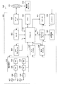
- FIG. 1 is a diagram illustrating an example of an overall configuration of a system according to an embodiment of the present disclosure. It is a figure for explaining BWP. It is a figure for explaining beam sweeping.
- FIG. 11 is a sequence diagram illustrating an example of a flow of a typical measurement report process executed by a base station and a terminal device. It is a block diagram showing an example of the composition of the base station concerning the embodiment. It is a block diagram showing an example of composition of a terminal unit concerning the embodiment.
- FIG. 4 is a diagram for describing an outline of commonality information according to the first embodiment. It is a figure for explaining the example in the case where all the beams which belong to a beam group are common.
- FIG. 9 is a diagram for describing a specific example in a case where a subset of a beam group is common.
- FIG. 3 is a diagram for describing an example of commonality information according to the embodiment.
- FIG. 3 is a diagram for describing an example of commonality information according to the embodiment. It is a figure for explaining a technical subject of a 2nd embodiment. It is a figure for explaining an example of the linkage of the beam sweeping using a plurality of beam groups concerning the embodiment. It is a sequence which shows an example of the flow of the beam selection processing performed by the system concerning the embodiment.
- FIG. 4 is a block diagram illustrating a first example of a schematic configuration of an eNB. It is a block diagram which shows the 2nd example of a schematic structure of eNB. It is a block diagram which shows an example of a schematic structure of a smart phone. It is a block diagram showing an example of a schematic structure of a car navigation device.
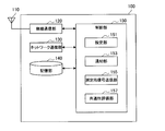
- FIG. 1 is a diagram illustrating an example of an overall configuration of a system 1 according to an embodiment of the present disclosure.
- the system 1 includes a base station 100 (100A and 100B), a terminal device 200 (200A and 200B), a core network (Core Network) 20, and a PDN (Packet Data Network) 30.
- a base station 100 100A and 100B
- a terminal device 200 200A and 200B
- a core network Core Network
- PDN Packet Data Network
- the base station 100 is a communication device that operates the cell 11 (11A and 11B) and provides a wireless service to one or more terminal devices located inside the cell 11.
- the base station 100A provides a wireless service to the terminal device 200A
- the base station 100B provides a wireless service to the terminal device 200B.
- the cell 11 can be operated according to any wireless communication scheme such as LTE or NR (New Radio).
- the base station 100 is connected to the core network 20.
- the core network 20 is connected to the PDN 30.
- the core network 20 may include, for example, an MME (Mobility Management Entity), an S-GW (Serving PDgateway), a P-GW (PDN (gateway), a PCRF (Policy and Charging Rule Function), and an HSS (Home Subscriber Server).
- the MME is a control node that handles signals of the control plane, and manages a moving state of the terminal device.
- the S-GW is a control node that handles user plane signals, and is a gateway device that switches a user data transfer path.
- the P-GW is a control node that handles user plane signals, and is a gateway device serving as a connection point between the core network 20 and the PDN 30.
- the PCRF is a control node that controls policies such as QoS (Quality of Service) and charging for bearers.
- the HSS is a control node that handles subscriber data and performs service control.
- the terminal device 200 is a communication device that performs wireless communication with the base station 100 based on control by the base station 100.
- the terminal device 200 may be a so-called user terminal (User @ Equipment: UE).
- the terminal device 200 transmits an uplink signal to the base station 100 and receives a downlink signal from the base station 100.
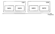
- FIG. 2 is a diagram for explaining BWP.
- CC # 1 includes a plurality of BWPs (# 1 and # 2)
- CC # 2 includes a plurality of BWPs (# 1 and # 2).
- the number after # indicates an index.
- BWPs included in different CCs indicate different BWPs even if the index is the same.
- BWP is obtained by dividing CC which is one operation frequency bandwidth (operation band width) into a plurality of frequency bandwidths. In each BWP, a different subcarrier spacing can be set.
- This BWP has been standardized as a basic frame format of NR of 3GPP Rel15.
- the subcarrier interval was fixed at 15 kHz.
- the subcarrier interval can be set to 60 kHz, 120 kHz or 240 kHz. The longer the subcarrier interval, the shorter the OFDM symbol length. For example, in LTE, since the subcarrier interval is 15 kHz, one slot can be transmitted per 1 ms, in other words, 14 OFDM symbols can be transmitted.
- two slots can be transmitted when the subcarrier interval is 60 kHz, four slots when the subcarrier interval is 120 kHz, and eight slots when the subcarrier interval is 240 kHz.
- the OFDM symbol length is reduced. Accordingly, it is possible to provide a frame configuration suitable for low-delay communication.
- BWP with different subcarrier intervals can be provided simultaneously. Therefore, the NR can simultaneously provide a plurality of BWPs corresponding to different use cases.
- a BWP capable of transmitting and receiving is also called an active BWP.
- the number of BWPs that can transmit and receive at the same time is also called the number of active BWPs.
- the number of active BWPs of the base station 100 is plural.
- the number of active BWPs of the terminal device 200 may be one.
- the terminal device 200 having a plurality of active BWPs is expected to appear in the future. These scenarios are shown in Table 1 below.
- the technology according to the present disclosure can be applied to both the case where the number of active BWPs of the terminal device 200 is one and the case where the number of active BWPs is plural.
- the base station 100 can improve communication quality by performing beamforming and communicating with the terminal device 200, for example.
- a beamforming method there are a method of generating a beam that follows the terminal device 200 and a method of selecting a beam that follows the terminal device 200 from candidate beams.
- the former method is computationally expensive every time a beam is generated, and thus it is unlikely that the former method will be adopted in a future wireless communication system (for example, 5G).
- the latter method is also adopted in FD-MIMO (Full Dimension Multiple Input Multiple Output) of Release 13 of 3GPP (Third Generation Partnership Project).
- the latter method is also called codebook based beam forming.
- the base station 100 prepares (or generates) beams in all directions in advance, and selects a beam suitable for the target terminal device 200 from among the beams prepared in advance. And communicates with the terminal device 200 using the selected beam. For example, when communication at 360 degrees in the horizontal direction is possible, the base station 100 prepares, for example, 360 types of beams at intervals of 1 degree. When making the beams overlap by half, the base station 100 prepares 720 types of beams. In the vertical direction, the base station 100 prepares a beam for 180 degrees, for example, from -90 degrees to +90 degrees.
- the terminal device 200 since the terminal device 200 only observes the beam, it is not necessary to know the existence of the codebook on the base station 100 side.
- a plurality of beams prepared by the base station 100 in advance are also referred to as beam groups below.
- the beam group can be defined for each frequency band, for example. Also, beams may be defined for each Rx / Tx beam and for each downlink / uplink.
- the measurement signal may also be referred to as a reference signal (Reference Signal). It is possible to select an optimal transmission signal (hereinafter also referred to as a Tx beam) based on the measurement result of the measurement signal transmitted while performing beam sweeping.
- a Tx beam an optimal transmission signal
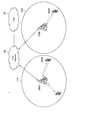
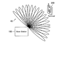
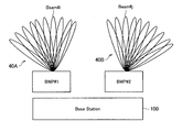
- FIG. 3 is a diagram for explaining beam sweeping.
- the base station 100 transmits the measurement signal while performing beam sweeping using the beam group 40 (that is, switching the Tx beam).
- the transmission while performing beam sweeping is hereinafter also referred to as beam sweeping transmission.
- terminal apparatus 200 measures the measurement signal transmitted by beam sweeping, and determines which Tx beam is most easily received. In this way, the optimal Tx beam of the base station 100 is selected.
- the base station 100 can select the optimal Tx beam of the terminal device 200 by exchanging the base station 100 and the terminal device 200 and performing the same procedure.
- an optimal receiving beam (hereinafter, also referred to as an Rx beam) can be selected based on a measurement result obtained by receiving the measuring signal while beam sweeping.
- the terminal device 200 transmits the measurement signal on the uplink.
- base station 100 receives the measurement signal while performing beam sweeping (that is, while switching Rx beams), and determines which Rx beam is most easily received.
- the optimal Rx beam of the base station 100 is selected.
- the terminal device 200 can select the optimal Rx beam of the terminal device 200.
- receiving while performing beam sweeping is also referred to as beam sweeping reception below.
- the side that receives and measures the measurement signal transmitted by beam sweeping reports the measurement result to the transmission side of the measurement signal.
- the measurement result includes information indicating which Tx beam is optimal.
- the optimal Tx beam is, for example, a Tx beam having the highest received power.
- the measurement result may include information indicating one Tx beam with the highest received power, or may include information indicating the top K Tx beams with the highest received power.
- the measurement result includes, for example, Tx beam identification information (eg, beam index) and information indicating the magnitude of the received power of the Tx beam (eg, RSRP (Reference ⁇ Signal ⁇ Received ⁇ Power)) in association with each other.
- Tx beam identification information eg, beam index
- RSRP Reference ⁇ Signal ⁇ Received ⁇ Power
- the measurement signal is transmitted by beam sweeping using each of the plurality of Tx beams belonging to the beam group. It can be said that each of the Tx beams is identified by a resource called a measurement signal.
- the measurement signal transmitted using the beam may be referred to as a beam resource. Further, the measurement signal transmitted by beam sweeping using the beam group may be referred to as a beam resource group.
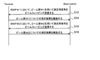
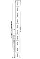
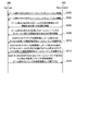
- FIG. 4 is a sequence diagram showing an example of a flow of a typical measurement report process executed by the base station and the terminal device.
- the base station beam-sweep-transmits the measurement signal using BWP # 1 beam group # 1 in BWP # 1 (step S12).
- the terminal device measures the measurement signal transmitted by beam sweeping transmission using beam group # 1 in BWP # 1, and reports the measurement result to the base station (step S14).
- the base station transmits a signal for measurement by beam sweeping using beam group # 2 for BWP # 2 (step S16).
- the terminal device performs measurement of the measurement signal transmitted by beam sweeping using beam group # 2 in BWP # 2, and reports the measurement result to the base station (step S18).
- TS38.214 stipulates that the base station transmits information indicating whether or not different reference signals may be considered to have been transmitted from the same base station. . More specifically, it is stipulated that the base station transmits information indicating whether or not the antenna ports # 0 and # 1 transmit beams in the same direction. However, such information merely indicates the relationship of beams between antenna ports, and is not information indicating the relationship of beams between different BWPs or between different CCs as in the proposed technology.
- the information specified by TS38.214 is information for each of the beams, and is not information for the beam group as in the proposed technology.
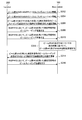
- FIG. 5 is a block diagram illustrating an example of a configuration of the base station 100 according to the present embodiment.
- the base station 100 includes an antenna unit 110, a wireless communication unit 120, a network communication unit 130, a storage unit 140, and a control unit 150.
- Antenna unit 110 The antenna unit 110 radiates a signal output by the wireless communication unit 120 into space as a radio wave.
- the antenna unit 110 converts a radio wave in space into a signal, and outputs the signal to the wireless communication unit 120.
- the antenna section 110 has a plurality of antenna elements and can form a beam.
- the wireless communication unit 120 transmits and receives signals. For example, the wireless communication unit 120 transmits a downlink signal to the terminal device and receives an uplink signal from the terminal device.
- the wireless communication unit 120 can form a plurality of beams by the antenna unit 110 and communicate with the terminal device.
- the network communication unit 130 transmits and receives information.
- the network communication unit 130 transmits information to another node and receives information from another node.
- the other nodes include other base stations and core network nodes.
- Storage unit 140 The storage unit 140 temporarily or permanently stores a program for the operation of the base station 100 and various data.
- Control unit 150 controls the overall operation of the base station 100 and provides various functions of the base station 100.
- the control unit 150 includes a setting unit 151, a notification unit 153, a measurement signal transmission unit 155, and a commonality evaluation unit 157.
- the setting unit 151 has a function of making settings related to communication with the terminal device 200. For example, the setting unit 151 performs resource configuration described later, and transmits resource configuration information indicating a resource configuration result to the terminal device 200.
- the notifier 153 has a function of notifying the terminal device 200 of commonality information described below.
- the notification unit 153 notifies information indicating the relationship between the beam directions of the downlink beam groups and / or setting information of the measurement report. Further, for example, the notifying unit 153 notifies information on linkage of beam sweeping using a plurality of beam groups. Further, for example, the notification unit 153 notifies an instruction for evaluating the commonality between the uplink beam groups and information specifying an uplink beam group to be subjected to beam sweeping.
- the measurement signal transmission unit 155 has a function of transmitting a measurement signal on the downlink. More specifically, the measurement signal transmitting unit 155 performs beam sweeping transmission of the measurement signal using a beam group defined for each of the plurality of frequency bandwidths.
- the commonality evaluation unit 157 has a function of evaluating commonality between uplink beam groups. More specifically, the commonality evaluation unit 157 measures a measurement signal beam-sweeped by the terminal device 200 using the beam group defined for each frequency bandwidth in each of the plurality of frequency bandwidths, and Assess commonality based on
- the control unit 150 may further include other components other than these components. That is, the control unit 150 can perform operations other than the operations of these components.
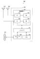
- FIG. 6 is a block diagram illustrating an example of a configuration of the terminal device 200 according to the present embodiment.
- the terminal device 200 includes an antenna unit 210, a wireless communication unit 220, a storage unit 230, and a control unit 240.
- Antenna unit 210 The antenna unit 210 radiates a signal output by the wireless communication unit 220 into space as a radio wave. Further, the antenna unit 210 converts a radio wave in space into a signal, and outputs the signal to the wireless communication unit 220.
- the antenna unit 210 has a plurality of antenna elements and can form a beam.
- Wireless communication unit 220 Wireless communication section 220 transmits and receives signals.
- the wireless communication unit 220 receives a downlink signal from a base station and transmits an uplink signal to the base station.
- the wireless communication unit 220 can form a plurality of beams using the antenna unit 210 and communicate with the base station.
- Storage unit 230 The storage unit 230 temporarily or permanently stores a program for operating the terminal device 200 and various data.
- Control unit 240 controls the overall operation of the terminal device 200 and provides various functions of the terminal device 200.
- the control unit 240 includes a measurement report unit 241 and a measurement signal transmission unit 243.
- the measurement report unit 241 has a function of measuring the measurement signal transmitted from the base station 100 and reporting the measurement result to the base station 100. More specifically, the measurement report unit 241 measures the measurement signal beam-sweeped by the base station 100 based on the commonality information notified from the base station 100, and reports the measurement result to the base station 100.
- the measurement signal transmitting unit 243 has a function of transmitting a measurement signal on the uplink. More specifically, the measurement signal transmitting unit 243 performs beam sweeping transmission of the measurement signal using a beam group defined for each of the plurality of frequency bandwidths.
- the control unit 240 may further include other components other than these components. That is, the control unit 240 can perform operations other than the operations of these components.
- First Embodiment the measurement result of the measurement signal transmitted by beam sweeping using the beam group defined in a certain frequency bandwidth is transmitted by beam sweeping transmission using the beam group defined in another frequency bandwidth. This is a form used as a measurement result of the measured signal for measurement.
- the technical problems of the present embodiment are as described above. Specifically, in an environment where a plurality of frequency bandwidths exist, it is burdensome for the terminal device to execute the beam selection procedure in the plurality of frequency bandwidths. This is because the more the number of times the beam selection procedure is executed, the more the amount of calculation increases, and accordingly the amount of power consumption increases. Further, radio resources for beam sweeping are prepared in all frequency bandwidths, so that radio resource overhead also increases.
- the base station 100 sets a beam group defined in each of the plurality of frequency bandwidths.
- the base station 100 performs resource configuration for a beam group defined in each of a plurality of frequency bandwidths.
- the resource configuration includes setting a radio resource (for example, a frequency resource and / or a time resource) used for beam sweeping transmission of the measurement signal using the beam group for each frequency bandwidth.
- the resource configuration may also include associating each of the plurality of beams belonging to the beam group with a measurement signal transmitted using the beam.
- the base station 100 (for example, the setting unit 151) transmits resource configuration information indicating a result of the resource configuration to the terminal device 200.
- the resource configuration information may include at least information indicating a radio resource used for beam sweeping transmission of the measurement signal using the beam group.
- the resource configuration information may include information for associating a frequency bandwidth with a beam group defined in the frequency bandwidth.
- the resource configuration information is, for each beam group, information that associates each of the plurality of beams belonging to the beam group, a measurement signal transmitted using the beam, and a radio resource used for transmitting the measurement signal. May be included.
- the base station 100 (for example, the notification unit 153) notifies the terminal device 200 of information on the commonality between the beam groups defined in different frequency bandwidths.
- the information on the commonality between the beam groups is hereinafter also referred to as commonality information.
- commonality information For notification of the commonality information, higher layer signaling (Higher layer signaling), system information, DCI (Downlink Control information), or dedicated signaling (dedicated signaling) may be used.
- the technical features of the present embodiment will be described using a first beam group defined corresponding to the first frequency bandwidth and a second beam group defined corresponding to the second frequency bandwidth. Is done.
- the first frequency bandwidth is also called BWP # 1
- the first beam group is also called beam group # 1
- the second frequency bandwidth is also called BWP # 2
- the second beam group is beam group Also called # 2.
- the measurement is performed on the beam group # 1 and at least a part of the measurement on the beam group # 2 is omitted.
- FIG. 7 is a diagram for explaining an outline of the commonality information according to the present embodiment.
- base station 100 can transmit beam group 40A as beam group # 1 defined in BWP # 1, and transmits beam group 40B as beam group # 2 defined in BWP # 2. It is possible.
- the beam directions of the beam group # 1 and the beam group # 2 may coincide. For example, as shown in FIG. 7, the direction of beam #i belonging to beam group # 1 and the direction of beam #j belonging to beam group # 2 match.
- the commonality information may include information indicating the relationship between the beam directions of the beam groups.
- the commonality information may include information indicating that the direction of the beam #i and the direction of the beam #j are common.
- the commonality information may include measurement report setting information.
- the commonality information includes information for setting one of the measurement results of the beam #i and the beam #j to be reported instead of the other measurement result.
- the terminal device 200 can use one measurement result of the beam #i and the beam #j instead of the other measurement result.
- the terminal device 200 can measure one of the beams #i and #j and omit the measurement of the other. Thereby, the load on the terminal device 200 is reduced.
- the commonality information includes information indicating the relationship between the beam directions of the beam groups and the case where the commonness information includes the setting information of the measurement report will be sequentially described in detail.
- the commonality information may include information indicating the relationship between the direction (that is, directivity) of the beam between the beam groups.
- the commonality information may include information indicating whether or not the beam direction characteristics are common between a plurality of beam groups defined in different frequency bandwidths.
- the commonality information may include information indicating that at least a part of the direction of the beam belonging to the beam group # 1 and the direction of the beam belonging to the beam group # 2 are common.
- the fact that the directions of a plurality of beams are common means that the directions of the plurality of beams are the same.
- the fact that the directions of the plurality of beams are common means that the analog circuit of the base station 100 has been calibrated so that the plurality of beams are transmitted in the same direction.
- the commonality information indicates that the direction (that is, the directivity) of the beam belonging to the beam group # 1 and the direction of the beam belonging to the beam group # 2 are all common. Includes information indicating that For example, the commonality information includes identification information of the beam group # 1 and identification information of the beam group # 2, and information indicating that the beam direction is common between the beam group # 1 and the beam group # 2.
- the identification information of the beam group includes the index of the beam group (for example, the beam group ID), the index of the beam belonging to the beam group (for example, the beam ID), and the measurement signal transmitted by beam sweeping using the beam group. Or information indicating a radio resource for beam sweeping transmission using a beam group.
- FIG. 8 is a diagram for explaining a specific example in a case where all the beams belonging to the beam group are common.
- base station 100 can transmit beam group 40A as beam group # 1, and can transmit beam group 40B as beam group # 2.
- Beam group # 1 and beam group # 2 include the following beams, respectively.
- the commonality information includes information indicating that the direction of the beam belonging to the beam group # 1 and the direction of the beam belonging to the beam group # 2 are common.
- the terminal device 200 (for example, the measurement report unit 241) measures the measurement signal beam-sweeping-transmitted using the beam group by the base station 100 based on the commonality information notified from the base station 100, and performs measurement. Report the results. Specifically, terminal apparatus 200 measures which beam group among a plurality of beam groups that can be used for beam sweeping transmission of a measurement signal by base station 100 based on the commonality information notified from base station 100. Select whether to target. Then, the terminal device 200 measures the beam group that is the measurement target, and does not measure the beam group that is not the measurement target. The terminal device 200 reports the measurement result of the beam group to be measured to the base station 100 instead of the measurement result of the beam group not to be measured.
- the terminal device 200 reports the measurement result of the beam group # 1 as the measurement result of the beam group # 2.
- the terminal device 200 compares the measurement result of the measurement signal transmitted by beam sweeping using the beam group # 1 with the measurement signal transmitted by beam sweeping using the beam group # 2. Is reported to the base station 100 instead of the measurement result.
- the terminal device 200 does not have to measure the measurement signal transmitted by beam sweeping using the beam group # 2. In that case, the terminal device 200 can omit the measurement for the beam group # 2, and the burden is reduced.
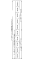
- FIG. 9 is a sequence diagram illustrating an example of a flow of a beam selection process performed by the system 1 according to the present embodiment.
- the base station 100 and the terminal device 200 are involved in this sequence.
- the base station 100 transmits resource configuration information for the beam group # 1 to the terminal device 200 (Step S102). Further, the base station 100 transmits the resource configuration for the beam group # 2 to the terminal device 200 (Step S104).
- the base station 100 transmits commonality information including information indicating that the direction of the beam belonging to the beam group # 1 and the direction of the beam belonging to the beam group # 2 are common to the terminal device 200 (step S106). ).
- the terminal device 200 determines to report the measurement results for the beam groups # 1 and # 2 based on the measurement results for the beam group # 1, based on the received commonality information (step S108). .
- base station 100 performs beam sweeping transmission of the measurement signal using beam group # 1 in BWP # 1 (step S110).
- terminal apparatus 200 performs measurement of the measurement signal transmitted by beam sweeping using beam group # 1 in BWP # 1, and reports the measurement result to base station 100 (step S112).
- base station 100 performs beam sweeping transmission of the measurement signal using beam group # 2 in BWP # 2 (step S114).
- terminal apparatus 200 reports the measurement result of the measurement signal transmitted by beam sweeping using beam group # 1 in BWP # 1 to base station 100 as the measurement result of beam group # 2 (step).
- S116 ).
- the base station 100 may omit transmission of the measurement signal using a beam common to beams belonging to other beam groups among beams belonging to the plurality of beam groups. Specifically, the base station 100 may omit the process in step S114. In this case, radio resources for beam sweeping transmission of the measurement signal in BWP # 2 can be released, and resource efficiency can be improved.
- the commonality information includes information indicating that a part of the direction of the beam belonging to the beam group # 1 and a part of the direction of the beam belonging to the beam group # 2 are common.
- the commonality information includes information indicating that the direction of the beam belonging to the subset of the beam group # 1 and the direction of the beam belonging to the beam group # 2 are common.
- the commonality information may include identification information of the beam group # 1 and identification information of the beam group # 2, and information indicating a subset of the beam group # 1 having the same beam direction as the beam group # 2.
- the beam direction may be common between the subset of the beam group # 1 and the subset of the beam group # 2.
- the commonality information includes information indicating that the beam direction is common between the subset of the beam group # 1 and the subset of the beam group # 2.
- the commonality information may include identification information of the beam group # 1 and identification information of the beam group # 2, and information indicating a subset of the beam group # 1 and a subset of the beam group # 2 having a common beam direction. .
- FIG. 10 is a diagram for explaining a specific example in a case where a subset of the beam group is common.
- base station 100 can transmit beam group 40A as beam group # 1, and can transmit beam group 40B as beam group # 2.
- the beam group # 1 and the beam group # 2 include the following beams, respectively.
- the commonality information includes information indicating that the direction of the beam belonging to the subset of the beam group # 1 and the direction of the beam belonging to the beam group # 2 are common.
- the terminal device 200 (for example, the measurement report unit 241), based on the commonality information notified from the base station 100, among a plurality of beam groups that can be used for beam sweeping transmission of the measurement signal by the base station 100 Select which beam group is to be measured. Further, terminal apparatus 200 specifies which subset of the beam group to be measured is to be reported instead of the measurement result of the beam group not to be measured. The terminal device 200 reports the measurement result of the specified subset of the beam group to be measured to the base station 100 instead of the measurement result of the beam group not to be measured.
- the terminal device 200 reports the measurement result of the subset of the beam group # 1 as the measurement result of the beam group # 2.
- the terminal device 200 transmits the measurement result of the measurement signal transmitted by beam sweeping using the beams # 1 to # 5 belonging to the beam group # 1 to the beam using the beam group # 2. It reports to base station 100 instead of the measurement result of the measurement signal transmitted by the sweep transmission.
- the received power of the beam # 8 is the highest in the beams # 1 to # 10
- the received power of the beam # 5 is the highest in the beams # 1 to # 5.
- terminal apparatus 200 reports that beam # 8 is optimal as a measurement result for beam group # 1, and reports that beam # 5 is optimal as a measurement result for beam group # 2.
- the terminal device 200 does not have to measure the measurement signal transmitted by beam sweeping using the beam group # 2. In that case, the terminal device 200 can omit the measurement for the beam group # 2, and the burden is reduced.
- the commonality information may include measurement report setting information.
- the commonality information may include information for setting to report the measurement result for the beam group # 2 based on the measurement result for the beam group # 1.
- the terminal device 200 can omit the measurement for the beam group # 2, and the burden is reduced.
- the commonality information is the beam group # 2 May include information for setting to report the measurement result for beam group # 1.
- the terminal device 200 (for example, the measurement report unit 241) reports a measurement result on the beam group # 1 based on the commonality information notified from the base station 100.
- Base station 100 handles the measurement result for beam group # 1 as the measurement result for beam group # 2.
- the terminal device 200 can omit the measurement for the beam group # 2, and the burden is reduced. Further, the terminal device 200 does not need to receive the setting for the beam group # 2 in the first place.
- the commonality information is the beam group # 1 And information indicating the range of the beam belonging to the beam group # 1 to be reported as the measurement result of each of the beam group # 2.
- the commonality information may include information indicating a range of a beam belonging to the beam group # 1 to be reported as a measurement result of the beam group # 2.
- the range of beams belonging to beam group # 1 may be considered as a subset of beam group # 1.
- the terminal device 200 (for example, the measurement report unit 241) reports the measurement result on the subset of the beam group # 1 based on the commonality information notified from the base station 100. For example, the terminal device 200 reports the measurement results for all beams belonging to the beam group # 1 as the measurement results for the beam group # 1. In addition, the terminal device 200 reports, as the measurement result of the beam group # 2, the measurement result of the beams belonging to the beam group # 1 and in the range specified by the commonality information. Thus, terminal apparatus 200 can omit measurement for beam group # 2, and the burden is reduced. Further, the terminal device 200 does not need to receive the setting for the beam group # 2 in the first place.
- this point will be specifically described with reference to FIG.
- FIG. 11 is a diagram for explaining an example of the commonality information according to the present embodiment.
- beam group # 1 for BWP # 1 includes beams # 1 to # 10.
- the report target range for the beam group # 1 is the beams # 1 to # 10.
- the report target range for beam group # 2 is beams # 1 to # 5.
- the commonality information includes measurement report setting information indicating that the range of the report target for the beam group # 1 is the beams # 1 to # 10.
- the base station 100 notifies the terminal device 200 of information for setting to report a beam having the maximum RSRP in the beams # 1 to # 10 of the beam group # 1 as a measurement result of the beam group # 1.
- the terminal device 200 reports information indicating the beam having the maximum RSRP among the beams # 1 to # 10 among the beam group # 1 to the base station 100 as the measurement result of the beam group # 1.
- the commonality information includes measurement report setting information indicating that the report target range for beam group # 2 is beams # 1 to # 5.
- the base station 100 notifies the terminal device 200 of information for setting to report a beam having the maximum RSRP in the beams # 1 to # 5 of the beam group # 1 as a measurement result of the beam group # 2. I do.
- the terminal device 200 reports information indicating the beam having the largest RSRP among the beams # 1 to # 5 in the beam group # 1 to the base station 100 as the measurement result of the beam group # 2.
- the base station 100 only needs to set the measurement report, and does not need to notify the information indicating the relationship of the beam direction between the beam groups.
- the commonality information indicates the measurement of each of the beam group # 1 and the beam group # 2. It may include information indicating a combination of subsets of beam group # 1 to be reported as a result.
- beam group # 1 is assumed to include a plurality of subsets.
- the commonality information includes information indicating a combination of target subsets to be reported as a measurement result for beam group # 1, that is, a combination including all subsets of beam group # 1.
- the commonality information includes information indicating a combination of target subsets to be reported as a measurement result of the beam group # 2, that is, information indicating a combination of a subset of the beam group # 1 having the same beam direction as the beam group # 2. .
- the terminal device 200 (for example, the measurement report unit 241) reports the measurement result on the subset of the beam group # 1 based on the commonality information notified from the base station 100. For example, the terminal device 200 reports the measurement result of the combination including all the subsets belonging to the beam group # 1 as the measurement result of the beam group # 1. Further, terminal apparatus 200 reports, as the measurement result of beam group # 2, the measurement result of the combination of the subset of beam group # 1 having the same beam direction as beam group # 2. Thus, terminal apparatus 200 can omit measurement for beam group # 2, and the burden is reduced. Further, the terminal device 200 does not need to receive the setting for the beam group # 2 in the first place.
- this point will be specifically described with reference to FIG.
- FIG. 12 is a diagram for explaining an example of the commonality information according to the present embodiment.
- beam group # 1 for BWP # 1 includes beams # 1 to # 10.
- the beam group # 1 for BWP # 1 includes a subset # 1 including beams # 1 to # 5 and a subset # 2 including beams # 6 to # 10.
- the report target for beam group # 1 is a combination of subsets # 1 and # 2.
- the report target for beam group # 2 is subset # 1.
- the commonality information includes measurement report setting information in which the report target for the beam group # 1 is a combination of the subsets # 1 and # 2.
- the base station 100 notifies the terminal device 200 of information for setting to report a beam having the maximum RSRP in the subsets # 1 and # 2 of the beam group # 1 as a measurement result of the beam group # 1.
- the terminal device 200 transmits information indicating the beam having the largest RSRP among the beams # 1 to # 10 belonging to the combination of the subsets # 1 and # 2 in the beam group # 1 as the measurement result for the beam group # 1. Report to station 100.
- the commonality information includes measurement report setting information that sets the report target for the beam group # 2 as the subset # 1.
- the base station 100 notifies the terminal device 200 of information for setting to report a beam having the maximum RSRP in the subset # 1 of the beam group # 1 as a measurement result of the beam group # 2.
- terminal apparatus 200 reports information indicating the beam having the largest RSRP among beams # 1 to # 5 belonging to subset # 1 of beam group # 1 to base station 100 as a measurement result for beam group # 2. .
- the commonality information transmitted in step S106 includes information for setting to report the measurement result for beam group # 2 based on the measurement result for beam group # 1.
- Second Embodiment is performed over a plurality of frequency bandwidths while switching the frequency bandwidth to be used.
- the number of simultaneously usable frequency bandwidths may be limited due to the capability of the terminal device 200.
- the number of frequency bandwidths that can be used simultaneously by the terminal device 200 may be one.
- the terminal device 200 can transmit and receive signals in a plurality of frequency bandwidths by switching the frequency bandwidth to be used.
- the beam selection procedure can be performed while switching the used frequency bandwidth. This will be described with reference to FIG.
- FIG. 13 is a diagram for explaining the technical problem of the present embodiment. As shown in FIG. 13, beam sweeping is performed in a time zone in which BWP # 3 is active, and then beam sweeping is performed in a time zone in which BWP # 4 is active. However, if the active BWP is switched frequently, it may be difficult to complete beam sweeping within the time when one BWP is active.
- the beam sweeping method shown in FIG. 13 is realized by 3GPP @ Rel15.
- the base station 100 (for example, the measurement signal transmitting unit 155) according to the present embodiment uses a beam sweep using a beam group defined in a certain frequency bandwidth. Part of the ping is represented by beam sweeping using beams defined in other frequency bandwidths. Thereby, even when it is difficult to complete beam sweeping within the time when one BWP is active, it is possible to perform beam sweeping over a plurality of BWPs while switching BWPs. .
- the third frequency bandwidth is also called BWP # 3
- the third beam group is also called beam group # 3
- the fourth frequency bandwidth is also called BWP # 4
- the fourth beam group is beam group Also called # 4. It is assumed that at least a part of the beam direction is common to the beam group # 3 and the beam group # 4. In this case, of the beam sweeping using the beam group # 3, the beam sweeping using the beam common to the beam group # 4 is represented by the beam sweeping using the beam group # 4.
- the base station 100 (for example, the measurement signal transmitting unit 155) transmits a subset of the beam group # 3 and a beam group # 4 or a subset thereof having the same beam direction as the other subset of the beam group # 3. Correspond. Such association is also called linkage. Then, the base station 100 performs beam sweeping transmission of the measurement signal using the subset of the linked beam group # 3 and the beam group # 4 or the subset thereof.
- the base station 100 (for example, the notification unit 153) notifies the terminal device 200 of the information on the linkage as the commonality information.
- the commonality information reports the measurement result of the subset of the beam group # 3 and the measurement result of the beam belonging to the beam group # 4 having the same beam direction as the other subset of the beam group # 3 in association with each other.
- the commonality information includes at least information indicating a subset of the beam group # 3 and a beam group # 4 or a subset thereof to be linked.
- the terminal device 200 (for example, the measurement report unit 241) measures the measurement result for the subset of the beam group # 3 and the beam belonging to the beam group # 4 having the same direction as the beam belonging to another subset of the beam group # 3. The measurement results are reported in association with each other. More specifically, terminal apparatus 200 transmits a measurement signal transmitted using a subset of beam group # 3 and a beam belonging to beam group # 4 having the same direction as a beam belonging to another subset of beam group # 3. The measurement result of the measurement signal transmitted using the measurement result is reported as the measurement result of beam group # 3.
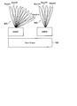
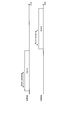
- FIG. 14 is a diagram illustrating an example of a linkage of beam sweeping using a plurality of beam groups according to the present embodiment.
- the base station 100 can use BWP # 3 and BWP # 4, and it is assumed that the terminal device 200 can simultaneously use one BWP. Further, it is assumed that base station 100 can transmit beam group # 3 defined by BWP # 3 and can transmit beam group # 4 defined by BWP # 4. Further, the beam group # 3 and the beam group # 4 include the following beams, respectively.
- Beam group # 4 Beam # 1, beam # 2, ..., beam # 10
- beams having the same index have the same directivity.
- the base station 100 links the subset of the beam group # 3 with the subset of the beam group # 4 having the same beam direction as the other subset of the beam group # 3. For example, base station 100 links beams # 1 to # 5 belonging to beam group # 3 and beams # 6 to # 10 belonging to beam group # 4.
- the base station 100 notifies the terminal device 200 of information for setting to report the measurement result of each linked subset in association with each other. Then, as shown in FIG. 14, the base station 100 performs beam sweeping transmission of the measurement signal using each of the linked subsets while switching from BWP # 3 to # 4.
- the base station 100 performs beam sweeping transmission of the measurement signal using the beams # 1 to # 5 belonging to the beam group # 3 during a time period when BWP # 3 is active.
- base station 100 performs beam sweeping transmission of the measurement signal using beams # 6 to # 10 belonging to beam group # 4 during a time period when BWP # 4 is active.
- Terminal apparatus 200 transmits measurement signals transmitted using beams # 1 to # 5 belonging to beam group # 3 and measurement signals transmitted using beams # 6 to # 10 belonging to beam group # 4. ,Measure. Then, terminal apparatus 200 reports these measurement results to base station 100 as measurement results for beam group # 3. For example, the terminal device 200 reports, to the base station 100, the values of the beam ID and the RSRP of one of the beams having the highest RSRP or the upper K beams having the highest RSRP.
- the terminal device 200 reports the highest one beam, it can be said that beam selection is executed by the terminal device 200.
- the terminal device 200 reports K beams with a high RSRP, the base station 100 selects a beam from the K beams.
- a part of the beam sweeping using the beam group # 3 is represented by the beam sweeping using the beam group # 4. Therefore, even when it is difficult to complete the beam sweeping within the time when one BWP is active, it is possible to perform the beam sweeping seamlessly while switching the BWP.
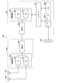
- FIG. 15 is a sequence diagram illustrating an example of a flow of a beam selection process performed by the system 1 according to the present embodiment.
- the base station 100 and the terminal device 200 are involved in this sequence.
- the base station 100 transmits resource configuration information for the beam group # 3 to the terminal device 200 (Step S202). Further, the base station 100 transmits the resource configuration for the beam group # 4 to the terminal device 200 (Step S204).
- the base station 100 transmits first commonality information including information indicating the relationship between the beam directions of the beam groups # 3 and # 4 to the terminal device 200 (Step S206).
- the first commonality information includes information indicating that the direction of the beam belonging to beam group # 3 and the direction of the beam belonging to beam group # 4 are common.
- the base station 100 transmits, to the terminal device 200, the second common information including information on the linkage of beam sweeping using the beam groups # 3 and # 4 (Step S208).
- the second commonality information includes a measurement result for the subset of the beam group # 3 and a measurement result for the beam belonging to the beam group # 4 having the same beam direction as the other subset of the beam group # 3. , And information to be set to be reported in association with each other.
- the base station 100 performs beam sweeping transmission of the measurement signal using the subset of the beam group # 3 during the time period when BWP # 3 is active (step S210).
- base station 100 performs beam sweeping transmission of the measurement signal using the subset of beam group # 4 having the same beam direction as the other subset of beam group # 3 during the time period when BWP # 4 is active. (S212).
- terminal apparatus 200 reports the measurement result of the measurement signal transmitted by beam sweeping in BWP # 3 and BWP # 4 to base station 100 as the measurement result of beam group # 3 (step S214).
- FIG. 16 is a diagram for explaining another example of the linkage of beam sweeping using a plurality of beam groups according to the present embodiment.
- the base station 100 can use BWP # 3 and BWP # 4, and the terminal device 200 can use two BWPs at the same time. Further, it is assumed that base station 100 can transmit beam group # 3 defined by BWP # 3 and can transmit beam group # 4 defined by BWP # 4. Further, the beam group # 3 and the beam group # 4 include the following beams, respectively.
- Beam group # 4 Beam # 1, beam # 2, ..., beam # 10
- beams having the same index have the same directivity.
- the base station 100 simultaneously performs beam sweeping transmission of the measurement signal using the linked subset of the beam group # 3 and the subset of the beam group # 4. That is, the base station 100 may simultaneously perform beam sweeping using a linked beam group in a plurality of BWPs.
- the base station 100 evaluates the commonality of a plurality of uplink beam groups, and the terminal device 200 omits the beam sweeping using one of the plurality of beam groups evaluated to be common. .
- the load on the terminal device 200 in the case where the measurement signal is beam-sweep-transmitted on the downlink and the downlink Tx beam is selected has been reduced.
- the load on the terminal device 200 in the case where the measurement signal is beam-sweep-transmitted on the uplink and a Tx beam for the uplink is selected is reduced.
- the base station 100 can determine whether or not the beam directions of a plurality of uplink beam groups defined in different frequency bandwidths are common, but it is difficult for the terminal device 200 to determine. is there.
- the base station 100 (for example, the setting unit 151) sets a beam group defined in each of a plurality of frequency bandwidths.
- the beam group is an uplink Tx beam.
- the base station 100 performs resource configuration for a beam group including a plurality of uplink Tx beams defined in each of a plurality of frequency bandwidths.
- the terminal device 200 can transmit a beam group # 5 (corresponding to a fifth beam group) defined in BWP # 5 (corresponding to a fifth frequency bandwidth).
- terminal apparatus 200 can transmit beam group # 6 (corresponding to the sixth beam group) defined in BWP # 6 (corresponding to the sixth frequency bandwidth).
- the beam group # 5 and the beam group # 6 include the following beams, respectively. Beam group # 5: Beam # 1, beam # 2, ..., beam # 10
- Beam group # 6 Beam # 1, beam # 2, ..., beam # 10
- beams having the same index have the same directivity.
- the base station 100 (for example, the notification unit 153) includes information that instructs to perform beam sweeping transmission of a measurement signal using a plurality of uplink beams defined in each of a plurality of frequency bandwidths.
- the sex information is notified to the terminal device 200.
- the base station 100 notifies the terminal device 200 of information instructing to perform beam sweeping transmission of the measurement signal using the beam group # 5 and the beam group # 6.
- the base station 100 instructs the terminal device 200 to perform beam sweeping transmission of the measurement signal using the beam group # 5, and then performs beam sweeping of the measurement signal using the beam group # 6. Instruct ping transmission.
- the terminal device 200 (for example, the measurement signal transmission unit 243) transmits a measurement signal using a plurality of uplink beam groups defined in each of a plurality of frequency bandwidths based on the notification from the base station 100. Perform beam sweeping transmission. For example, the terminal device 200 performs beam sweeping transmission of the measurement signal using the beam group # 5 and the beam group # 6.
- the base station 100 (for example, the commonality evaluation unit 157) measures the measurement signal beam-sweeping-transmitted by the terminal device 200 using the plurality of uplink beams, and outputs the plurality of uplink beams. Assess the commonality of Specifically, the base station 100 determines whether the direction of the beam belonging to the beam group # 5 and the direction of the beam belonging to the beam group # 6 match based on the measurement result, and further specifies the matching beam. I do. For example, regarding the above specific example, the base station 100 determines that the directions of the beams belonging to the beam group # 5 and the directions of the beams belonging to the beam group # 6 all match.
- the base station 100 (for example, the notification unit 153) notifies information specifying an uplink beam group to be subjected to beam sweeping based on the evaluation result.
- the base station 100 for example, the notification unit 153
- the commonality information includes information instructing not to perform beam sweeping transmission of a measurement signal using an uplink beam group defined in a specific frequency bandwidth.
- An uplink beam group defined in a specific frequency bandwidth here is a beam group whose beam direction coincides with another beam group, or whose beam direction coincides with a subset of another beam group. is there.
- the commonality information may include information instructing not to perform beam sweeping transmission of the measurement signal using the beam group # 6.
- the commonality information may be information that instructs to delete the resource configuration related to the beam group # 6.
- the commonality information includes information instructing to perform beam sweeping transmission of a measurement signal using an uplink beam group defined in a specific frequency bandwidth.
- the uplink beam group defined in a specific frequency bandwidth means that the beam direction coincides with another beam group, or a subset of the beam group coincides with the beam direction of another beam group.
- a beam group A beam group.
- the commonality information may include information instructing to perform beam sweeping transmission of the measurement signal using the beam group # 5.
- the terminal device 200 (for example, the measurement signal transmitting unit 243) performs the measurement using some of the uplink beam groups among the uplink beam groups defined in each of the plurality of frequency bandwidths. Beam sweeping transmission of a measurement signal using another uplink beam group is performed without performing beam sweeping transmission of the signal.
- the terminal device 200 does not perform beam sweeping transmission of the measurement signal using the beam group # 6, but performs beam sweeping transmission of the measurement signal using the beam group # 5. Since the beam directions of beam group # 5 and beam group # 6 are common, base station 100 can handle the measurement result of beam group # 5 as the measurement result of beam group # 6. . That is, the base station 100 can omit the measurement for the beam group # 6. In addition, the terminal device 200 can omit the beam sweeping transmission of the measurement signal using the beam group # 6. Therefore, the burden on both the base station 100 and the terminal device 200 is reduced.
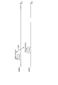
- FIG. 17 is a sequence diagram illustrating an example of a flow of a beam selection process performed by the system 1 according to the present embodiment.
- the base station 100 and the terminal device 200 are involved in this sequence.
- the base station 100 transmits resource configuration information for beam group # 5 to the terminal device 200 (Step S302).
- the base station 100 transmits the resource configuration for the beam group # 6 to the terminal device 200 (Step S304).
- the base station 100 transmits commonality information including information instructing to perform beam sweeping transmission of the measurement signal using each of the beam groups # 5 and # 6 to the terminal device 200 (Step S306).
- terminal apparatus 200 performs beam sweeping transmission of the measurement signal using beam group # 5 in BWP # 5 (step S308). Further, terminal device 200 performs beam sweeping transmission of the measurement signal using beam group # 6 in BWP # 6 (step S310).
- base station 100 measures the measurement signal transmitted by beam sweeping using each of beam groups # 5 and # 6, and evaluates the commonality of beam groups # 5 and # 6 based on the measurement result. (Step S312). Here, it is assumed that the beam groups # 5 and # 6 are determined to have the same beam direction.
- the base station 100 transmits commonality information including information instructing not to perform beam sweeping transmission of the measurement signal using the beam group # 6 to the terminal device 200 (step S314).
- the commonality information here may be information that instructs to delete the resource configuration related to the beam group # 6.
- the commonality information here may include information instructing to perform beam sweeping transmission of the measurement signal using the beam group # 5.
- terminal apparatus 200 performs beam sweeping transmission of the measurement signal using beam group # 5 in BWP # 5 (step S316).
- the base station 100 may be realized as any type of eNB (evolved ⁇ Node ⁇ B) such as a macro eNB or a small eNB.
- the small eNB may be an eNB that covers a cell smaller than a macro cell, such as a pico eNB, a micro eNB, or a home (femto) eNB.
- the base station 100 may be realized as another type of base station such as NodeB or BTS (Base @ Transceiver @ Station).
- the base station 100 may include a main unit (also referred to as a base station device) that controls wireless communication, and one or more RRHs (Remote / Radio / Head) arranged at a different location from the main unit. Further, various types of terminals described later may operate as the base station 100 by temporarily or semi-permanently executing the base station function.
- the terminal device 200 is a mobile terminal such as a smartphone, a tablet PC (Personal Computer), a notebook PC, a portable game terminal, a portable / dongle type mobile router or a digital camera, or a vehicle-mounted terminal such as a car navigation device. It may be realized as. Further, the terminal device 200 may be realized as a terminal that performs M2M (Machine @ To @ Machine) communication (also referred to as an MTC (Machine @ Type @ Communication) terminal). Furthermore, the terminal device 200 may be a wireless communication module (for example, an integrated circuit module configured with one die) mounted on these terminals.
- M2M Machine @ To @ Machine
- MTC Machine @ Type @ Communication
- FIG. 18 is a block diagram illustrating a first example of a schematic configuration of an eNB to which the technology according to the present disclosure can be applied.
- the eNB 800 includes one or more antennas 810 and a base station device 820. Each antenna 810 and the base station device 820 can be connected to each other via an RF cable.
- Each of the antennas 810 has a single or a plurality of antenna elements (for example, a plurality of antenna elements constituting a MIMO antenna), and is used for transmission and reception of radio signals by the base station apparatus 820.
- the eNB 800 includes a plurality of antennas 810 as illustrated in FIG. 18, and the plurality of antennas 810 may correspond to, for example, a plurality of frequency bands used by the eNB 800, respectively.
- FIG. 18 illustrates an example in which the eNB 800 includes a plurality of antennas 810, the eNB 800 may include a single antenna 810.
- the base station device 820 includes a controller 821, a memory 822, a network interface 823, and a wireless communication interface 825.
- the controller 821 may be, for example, a CPU or a DSP, and operates various functions of an upper layer of the base station device 820. For example, the controller 821 generates a data packet from the data in the signal processed by the wireless communication interface 825, and transfers the generated packet via the network interface 823. The controller 821 may generate a bundled packet by bundling data from a plurality of baseband processors, and transfer the generated bundled packet. Also, the controller 821 executes logic such as radio resource management (Radio Resource Control), radio bearer control (Radio Bear Control), mobility management (Mobility Management), inflow control (Admission Control), or scheduling (Scheduling). Function may be provided.
- Radio Resource Control Radio Resource Control
- Radio Bear Control radio bearer control
- Mobility Management Mobility Management
- Admission Control Inflow control
- scheduling scheduling
- the control may be executed in cooperation with a peripheral eNB or a core network node.
- the memory 822 includes a RAM and a ROM, and stores a program executed by the controller 821 and various control data (for example, a terminal list, transmission power data, scheduling data, and the like).
- the network interface 823 is a communication interface for connecting the base station device 820 to the core network 824.
- the controller 821 may communicate with a core network node or another eNB via the network interface 823.
- the eNB 800 and the core network node or another eNB may be connected to each other by a logical interface (for example, an S1 interface or an X2 interface).
- Network interface 823 may be a wired communication interface or a wireless communication interface for wireless backhaul.
- the network interface 823 may use a higher frequency band for wireless communication than the frequency band used by the wireless communication interface 825.
- the wireless communication interface 825 supports any of the cellular communication methods such as LTE (Long Term Evolution) or LTE-Advanced, and provides wireless connection to a terminal located in the cell of the eNB 800 via the antenna 810.
- the wireless communication interface 825 may typically include a baseband (BB) processor 826, an RF circuit 827, and the like.
- the BB processor 826 may perform, for example, encoding / decoding, modulation / demodulation, multiplexing / demultiplexing, and the like.
- Each layer eg, L1, MAC (Medium Access Control), RLC (Radio Link Control), and PDCP) (Packet ⁇ Data ⁇ Convergence ⁇ Protocol)).
- the BB processor 826 may have some or all of the above-described logical functions instead of the controller 821.
- the BB processor 826 may be a module that includes a memory that stores a communication control program, a processor that executes the program, and a related circuit. The function of the BB processor 826 may be changed by updating the program. Good.
- the module may be a card or a blade inserted into a slot of the base station device 820, or may be a chip mounted on the card or the blade.
- the RF circuit 827 may include a mixer, a filter, an amplifier, and the like, and transmits and receives wireless signals via the antenna 810.
- the wireless communication interface 825 includes a plurality of BB processors 826 as shown in FIG. 18, and the plurality of BB processors 826 may correspond to, for example, a plurality of frequency bands used by the eNB 800, respectively.
- the wireless communication interface 825 includes a plurality of RF circuits 827 as shown in FIG. 18, and the plurality of RF circuits 827 may correspond to, for example, a plurality of antenna elements, respectively.
- FIG. 18 illustrates an example in which the wireless communication interface 825 includes a plurality of BB processors 826 and a plurality of RF circuits 827.
- the wireless communication interface 825 includes a single BB processor 826 or a single RF circuit 827. May be.
- one or more components included in the control unit 150 described with reference to FIG. 5 may be implemented in the wireless communication interface 825.
- the eNB 800 includes a module including a part (for example, the BB processor 826) or all of the wireless communication interface 825 and / or the controller 821, and the one or more components described above may be mounted on the module. Good.
- the module stores a program for causing a processor to function as the one or more components (in other words, a program for causing the processor to execute the operations of the one or more components).
- the program may be executed.
- a program for causing the processor to function as the one or more components is installed in the eNB 800, and the wireless communication interface 825 (for example, the BB processor 826) and / or the controller 821 executes the program.
- the eNB 800, the base station device 820, or the module may be provided as a device including the one or more components, and a program for causing a processor to function as the one or more components is provided. You may. Further, a readable recording medium on which the program is recorded may be provided.
- the wireless communication unit 120 described with reference to FIG. 5 may be implemented in the wireless communication interface 825 (for example, the RF circuit 827). Further, the antenna unit 110 may be mounted on the antenna 810. Further, the network communication unit 130 may be implemented in the controller 821 and / or the network interface 823. Further, the storage unit 140 may be implemented in the memory 822.
- FIG. 19 is a block diagram illustrating a second example of a schematic configuration of an eNB to which the technology according to the present disclosure can be applied.
- the eNB 830 includes one or more antennas 840, a base station device 850, and an RRH 860. Each antenna 840 and RRH 860 may be connected to each other via an RF cable. Further, the base station device 850 and the RRH 860 can be connected to each other by a high-speed line such as an optical fiber cable.
- Each of the antennas 840 has a single or a plurality of antenna elements (for example, a plurality of antenna elements constituting a MIMO antenna), and is used for transmission and reception of a radio signal by the RRH 860.
- the eNB 830 includes a plurality of antennas 840 as illustrated in FIG. 19, and the plurality of antennas 840 may correspond to, for example, a plurality of frequency bands used by the eNB 830, respectively.
- FIG. 19 illustrates an example in which the eNB 830 has a plurality of antennas 840, the eNB 830 may have a single antenna 840.
- the base station device 850 includes a controller 851, a memory 852, a network interface 853, a wireless communication interface 855, and a connection interface 857.
- the controller 851, the memory 852, and the network interface 853 are the same as the controller 821, the memory 822, and the network interface 823 described with reference to FIG.
- the wireless communication interface 855 supports any cellular communication scheme such as LTE or LTE-Advanced, and provides a wireless connection to a terminal located in a sector corresponding to the RRH 860 via the RRH 860 and the antenna 840.
- the wireless communication interface 855 may typically include a BB processor 856 and the like.
- the BB processor 856 is similar to the BB processor 826 described with reference to FIG. 18 except that the BB processor 856 is connected to the RF circuit 864 of the RRH 860 via the connection interface 857.
- the wireless communication interface 855 includes a plurality of BB processors 856 as illustrated in FIG.
- the plurality of BB processors 856 may correspond to, for example, a plurality of frequency bands used by the eNB 830, respectively.
- FIG. 19 illustrates an example in which the wireless communication interface 855 includes a plurality of BB processors 856, the wireless communication interface 855 may include a single BB processor 856.
- connection interface 857 is an interface for connecting the base station device 850 (wireless communication interface 855) to the RRH 860.
- the connection interface 857 may be a communication module for communication on the high-speed line that connects the base station device 850 (wireless communication interface 855) and the RRH 860.
- the RRH 860 includes a connection interface 861 and a wireless communication interface 863.
- connection interface 861 is an interface for connecting the RRH 860 (wireless communication interface 863) to the base station device 850.
- the connection interface 861 may be a communication module for communication on the high-speed line.
- the wireless communication interface 863 sends and receives wireless signals via the antenna 840.
- the wireless communication interface 863 may typically include an RF circuit 864 and the like.
- the RF circuit 864 may include a mixer, a filter, an amplifier, and the like, and transmits and receives wireless signals via the antenna 840.
- the wireless communication interface 863 includes a plurality of RF circuits 864 as shown in FIG. 19, and the plurality of RF circuits 864 may correspond to, for example, a plurality of antenna elements, respectively.
- FIG. 19 illustrates an example in which the wireless communication interface 863 includes a plurality of RF circuits 864, the wireless communication interface 863 may include a single RF circuit 864.
- one or more components may be implemented in the wireless communication interface 855 and / or the wireless communication interface 863.
- the controller 851 may include a module including a part (for example, the BB processor 856) or all of the wireless communication interface 855 and / or the controller 851, and the one or more components may be mounted on the module. Good.
- the module stores a program for causing a processor to function as the one or more components (in other words, a program for causing the processor to execute the operations of the one or more components).
- the program may be executed.
- a program for causing the processor to function as the one or more components is installed in the eNB 830, and the wireless communication interface 855 (for example, the BB processor 856) and / or the controller 851 executes the program.
- the eNB 830, the base station device 850, or the module may be provided as a device including the one or more components, and a program for causing a processor to function as the one or more components is provided. You may. Further, a readable recording medium on which the program is recorded may be provided.
- the wireless communication unit 120 described with reference to FIG. 5 may be implemented in the wireless communication interface 863 (for example, the RF circuit 864). Further, the antenna unit 110 may be mounted on the antenna 840. Further, the network communication unit 130 may be implemented in the controller 851 and / or the network interface 853. Further, the storage unit 140 may be implemented in the memory 852.
- FIG. 20 is a block diagram illustrating an example of a schematic configuration of a smartphone 900 to which the technology according to the present disclosure may be applied.
- the smartphone 900 includes a processor 901, a memory 902, a storage 903, an external connection interface 904, a camera 906, a sensor 907, a microphone 908, an input device 909, a display device 910, a speaker 911, a wireless communication interface 912, and one or more antenna switches 915. And one or more antennas 916, a bus 917, a battery 918, and an auxiliary controller 919.
- the processor 901 may be, for example, a CPU or an SoC (System on Chip), and controls functions of an application layer and other layers of the smartphone 900.
- the memory 902 includes a RAM and a ROM, and stores programs and data executed by the processor 901.
- the storage 903 may include a storage medium such as a semiconductor memory or a hard disk.
- the external connection interface 904 is an interface for connecting an external device such as a memory card or a USB (Universal Serial Bus) device to the smartphone 900.
- the camera 906 has an image sensor such as a CCD (Charge Coupled Device) or a CMOS (Complementary Metal Oxide Semiconductor), and generates a captured image.
- the sensor 907 may include, for example, a sensor group such as a positioning sensor, a gyro sensor, a geomagnetic sensor, and an acceleration sensor.
- Microphone 908 converts audio input to smartphone 900 into an audio signal.
- the input device 909 includes, for example, a touch sensor that detects a touch on the screen of the display device 910, a keypad, a keyboard, a button or a switch, and receives an operation or information input from a user.
- the display device 910 has a screen such as a liquid crystal display (LCD) or an organic light emitting diode (OLED) display, and displays an output image of the smartphone 900.
- Speaker 911 converts an audio signal output from smartphone 900 into audio.
- the wireless communication interface 912 supports any one of cellular communication systems such as LTE and LTE-Advanced, and executes wireless communication.
- the wireless communication interface 912 may typically include a BB processor 913, an RF circuit 914, and the like.
- the BB processor 913 may perform, for example, encoding / decoding, modulation / demodulation, multiplexing / demultiplexing, and perform various signal processing for wireless communication.
- the RF circuit 914 may include a mixer, a filter, an amplifier, and the like, and transmits and receives wireless signals via the antenna 916.
- the wireless communication interface 912 may be a one-chip module in which the BB processor 913 and the RF circuit 914 are integrated.
- the wireless communication interface 912 may include a plurality of BB processors 913 and a plurality of RF circuits 914 as illustrated in FIG. Although FIG. 20 illustrates an example in which the wireless communication interface 912 includes a plurality of BB processors 913 and a plurality of RF circuits 914, the wireless communication interface 912 includes a single BB processor 913 or a single RF circuit 914. May be.
- the wireless communication interface 912 may support other types of wireless communication methods such as a short-range wireless communication method, a close-range wireless communication method, or a wireless LAN (Local Area Network) method, in addition to the cellular communication method, In that case, a BB processor 913 and an RF circuit 914 for each wireless communication scheme may be included.
- Each of the antenna switches 915 switches the connection destination of the antenna 916 among a plurality of circuits (for example, circuits for different wireless communication systems) included in the wireless communication interface 912.
- Each of the antennas 916 has a single or a plurality of antenna elements (for example, a plurality of antenna elements constituting a MIMO antenna), and is used for transmission and reception of a radio signal by the radio communication interface 912.
- the smartphone 900 may include a plurality of antennas 916 as illustrated in FIG. Note that FIG. 20 illustrates an example in which the smartphone 900 includes a plurality of antennas 916; however, the smartphone 900 may include a single antenna 916.
- the smartphone 900 may include an antenna 916 for each wireless communication system.
- the antenna switch 915 may be omitted from the configuration of the smartphone 900.
- the bus 917 connects the processor 901, the memory 902, the storage 903, the external connection interface 904, the camera 906, the sensor 907, the microphone 908, the input device 909, the display device 910, the speaker 911, the wireless communication interface 912, and the auxiliary controller 919 to each other.
- the battery 918 supplies power to each block of the smartphone 900 illustrated in FIG. 20 via a power supply line partially indicated by a broken line in the drawing.
- the auxiliary controller 919 operates the minimum functions of the smartphone 900, for example, in the sleep mode.
- the smartphone 900 illustrated in FIG. 20 one or more components (the measurement report unit 241 and / or the measurement signal transmission unit 243) included in the control unit 240 described with reference to FIG. May be implemented. Alternatively, at least some of these components may be implemented in processor 901 or auxiliary controller 919.
- the smartphone 900 includes a module including a part (for example, the BB processor 913) or all of the wireless communication interface 912, the processor 901, and / or the auxiliary controller 919, and the one or more components in the module. May be implemented.
- the module stores a program for causing a processor to function as the one or more components (in other words, a program for causing the processor to execute the operations of the one or more components). The program may be executed.
- a program for causing a processor to function as the one or more components is installed in the smartphone 900, and the wireless communication interface 912 (for example, the BB processor 913), the processor 901, and / or the auxiliary controller 919 is installed in the smartphone 900.
- the program may be executed.
- the smartphone 900 or the module may be provided as a device including the one or more components, and a program for causing a processor to function as the one or more components may be provided. Further, a readable recording medium on which the program is recorded may be provided.
- the wireless communication unit 220 described with reference to FIG. 6 may be implemented in the wireless communication interface 912 (for example, the RF circuit 914). Further, the antenna unit 210 may be mounted on the antenna 916. Further, the storage unit 230 may be implemented in the memory 902.
- FIG. 21 is a block diagram illustrating an example of a schematic configuration of a car navigation device 920 to which the technology according to the present disclosure may be applied.
- the car navigation device 920 includes a processor 921, a memory 922, a GPS (Global Positioning System) module 924, a sensor 925, a data interface 926, a content player 927, a storage medium interface 928, an input device 929, a display device 930, a speaker 931, and wireless communication.
- An interface 933, one or more antenna switches 936, one or more antennas 937, and a battery 938 are provided.
- the processor 921 may be, for example, a CPU or an SoC, and controls the navigation function and other functions of the car navigation device 920.
- the memory 922 includes a RAM and a ROM, and stores programs executed by the processor 921 and data.
- the GPS module 924 measures the position (for example, latitude, longitude, and altitude) of the car navigation device 920 using a GPS signal received from a GPS satellite.
- the sensor 925 may include, for example, a sensor group such as a gyro sensor, a geomagnetic sensor, and a barometric pressure sensor.
- the data interface 926 is connected to the in-vehicle network 941 via a terminal (not shown), for example, and acquires data generated on the vehicle side such as vehicle speed data.
- the content player 927 reproduces the content stored on the storage medium (for example, CD or DVD) inserted into the storage medium interface 928.
- the input device 929 includes, for example, a touch sensor, a button, or a switch that detects a touch on the screen of the display device 930, and receives an operation or information input from a user.
- the display device 930 has a screen such as an LCD or an OLED display, and displays an image of a navigation function or content to be reproduced.
- the speaker 931 outputs the navigation function or the sound of the content to be reproduced.
- the wireless communication interface 933 supports any of the cellular communication systems such as LTE and LTE-Advanced, and executes wireless communication.
- the wireless communication interface 933 may typically include a BB processor 934, an RF circuit 935, and the like.
- the BB processor 934 may perform, for example, encoding / decoding, modulation / demodulation, and multiplexing / demultiplexing, and performs various signal processings for wireless communication.
- the RF circuit 935 may include a mixer, a filter, an amplifier, and the like, and transmits and receives wireless signals via the antenna 937.
- the wireless communication interface 933 may be a one-chip module in which the BB processor 934 and the RF circuit 935 are integrated.
- the wireless communication interface 933 may include a plurality of BB processors 934 and a plurality of RF circuits 935 as illustrated in FIG. Note that FIG. 21 illustrates an example in which the wireless communication interface 933 includes a plurality of BB processors 934 and a plurality of RF circuits 935. However, the wireless communication interface 933 includes a single BB processor 934 or a single RF circuit 935. May be.
- the wireless communication interface 933 may support other types of wireless communication methods such as a short-range wireless communication method, a close-range wireless communication method, or a wireless LAN method in addition to the cellular communication method.
- a BB processor 934 and an RF circuit 935 for each communication method may be included.
- Each of the antenna switches 936 switches the connection destination of the antenna 937 among a plurality of circuits (for example, circuits for different wireless communication systems) included in the wireless communication interface 933.
- Each of the antennas 937 has a single or a plurality of antenna elements (for example, a plurality of antenna elements constituting a MIMO antenna), and is used for transmission and reception of a radio signal by the radio communication interface 933.
- the car navigation device 920 may include a plurality of antennas 937 as shown in FIG. Although FIG. 21 illustrates an example in which the car navigation device 920 includes a plurality of antennas 937, the car navigation device 920 may include a single antenna 937.
- the car navigation device 920 may include an antenna 937 for each wireless communication system.
- the antenna switch 936 may be omitted from the configuration of the car navigation device 920.
- the battery 938 supplies power to each block of the car navigation device 920 shown in FIG. 21 via a power supply line partially indicated by a broken line in the drawing.
- the battery 938 stores power supplied from the vehicle.
- the car navigation device 920 includes a module including a part (for example, the BB processor 934) or all and / or the processor 921 of the wireless communication interface 933, and the one or more components are mounted in the module. You may.
- the module stores a program for causing a processor to function as the one or more components (in other words, a program for causing the processor to execute the operations of the one or more components). The program may be executed.
- a program for causing a processor to function as the one or more components is installed in the car navigation device 920, and the wireless communication interface 933 (for example, the BB processor 934) and / or the processor 921 executes the program.
- the car navigation device 920 or the module may be provided as a device including the one or more components, and a program for causing a processor to function as the one or more components may be provided. Good. Further, a readable recording medium on which the program is recorded may be provided.
- the wireless communication unit 220 described with reference to FIG. 6 may be implemented in the wireless communication interface 933 (for example, the RF circuit 935). Further, the antenna unit 210 may be mounted on the antenna 937. Further, the storage unit 230 may be implemented in the memory 922.
- the technology according to the present disclosure may be implemented as an in-vehicle system (or vehicle) 940 including one or more blocks of the above-described car navigation device 920, an in-vehicle network 941, and a vehicle-side module 942.
- vehicle-side module 942 generates vehicle-side data such as vehicle speed, engine speed, or failure information, and outputs the generated data to the on-vehicle network 941.
- the base station 100 performs setting of a beam group defined in each of a plurality of frequency bandwidths, and information about commonality between the beam groups defined in different frequency bandwidths.
- the terminal device 200 can omit the measurement of the beam common to the plurality of beam groups based on the information on the commonality between the beam groups notified from the base station 100. For example, it is assumed that the direction of the beam belonging to beam group # 1 or a subset thereof and the direction of the beam belonging to beam group # 2 are common.
- the terminal device 200 measures the measurement result of the measurement signal transmitted by beam sweeping using the beam group # 1 or a subset thereof to the measurement of the measurement signal transmitted by beam sweeping using the beam group # 2. As a result, it reports to base station 100. As described above, the terminal device 200 can omit the measurement for the common beam, so that the load on the terminal device 200 is reduced. That is, the calculation amount of the terminal device 200 in the beam selection procedure is reduced, and the power consumption is reduced. Further, an improvement in the throughput of the terminal device 200 can be realized.
- the base station 100 may omit transmission of the measurement signal using a beam common to the beams belonging to the other beam groups among the beams belonging to the plurality of beam groups. For example, it is assumed that the direction of the beam belonging to beam group # 1 or a subset thereof and the direction of the beam belonging to beam group # 2 are common. In this case, the base station 100 may omit the beam sweeping transmission of the measurement signal using the beam group # 2. In this case, it is possible to release radio resources for beam sweeping transmission of the measurement signal using the beam group # 2, and it is possible to improve resource efficiency.
- a plurality of frequency bandwidths are mainly described as a plurality of BWPs, but the present technology is not limited to such an example.
- the plurality of frequency bandwidths may be a plurality of CCs. That is, BWP in the description of each of the above embodiments may be replaced with CC.
- a communication device comprising: (2) The communication device according to (1), wherein the information regarding the commonality includes information indicating whether or not a characteristic regarding a direction of a beam is common among a plurality of the beam groups. (3) The information on the commonality includes a direction of a beam belonging to a first beam group defined in a first frequency bandwidth and a direction of a beam belonging to a second beam group defined in a second frequency band.
- the communication device including information indicating that at least a part of the direction is common.
- the information on the commonality includes information set to report the measurement result on the second beam group based on the measurement result on the first beam group, any of (1) to (4) above.
- the communication device according to claim 1.
- the information on the commonality includes information indicating a range of a beam belonging to the first beam group to be reported as a measurement result of each of the first beam group and the second beam group.
- the communication device 5).
- the first group of beams includes a plurality of subsets;
- the information on the commonality includes information indicating a combination of a subset of the first beam group to be reported as a measurement result of each of the first beam group and the second beam group.
- the communication device according to (5).
- the communication device according to any one of (1) to (7), wherein the communication device further includes a measurement signal transmission unit that performs beam sweep transmission of a measurement signal using the beam group.
- the information about the commonality has a direction common to a measurement result of a subset of a third beam group defined in the third frequency bandwidth and a beam belonging to another subset of the third beam group.
- the communication device further including information for setting a measurement result of a beam belonging to a fourth beam group defined in the fourth frequency bandwidth in association with the measurement result.
- the setting unit performs setting of an uplink beam group defined in each of the plurality of frequency bandwidths,
- the information on the commonality includes information instructing to perform beam sweeping transmission of a measurement signal using the plurality of uplink beams defined in each of the plurality of frequency bandwidths.
- the setting unit performs setting of an uplink beam group defined in each of the plurality of frequency bandwidths,
- the information on the commonality includes information indicating not to perform beam sweeping transmission of a measurement signal using the uplink beam group defined in the specific frequency bandwidth,
- the communication device according to any one of (1) to (10).
- the measurement report unit reports a measurement result of a first beam group defined in a first frequency bandwidth as a measurement result of a second beam group defined in a second frequency bandwidth.
- (14) The communication device according to (13), wherein the measurement report unit reports a measurement result of the subset of the first beam group as a measurement result of the second beam group.
- (15) The measurement report unit is configured to measure a subset of a third beam group defined in the third frequency bandwidth and a fourth beam having the same direction as a beam belonging to another subset of the third beam group.
- the communication device according to any one of (12) to (14), wherein a measurement result of a beam belonging to a fourth beam group defined in the frequency bandwidth described above is reported in association with each other.
- An uplink beam group is defined in each of the plurality of frequency bandwidths,
- the measurement report unit does not perform beam sweeping transmission of the measurement signal using a part of the uplink beam group, among the uplink beam group defined in each of the plurality of frequency bandwidths, Perform beam sweeping transmission of the measurement signal using the other uplink beam group,
- the communication device according to any one of (12) to (15).
- a communication method executed by the processor comprising: (18) Notified from another communication device, for a beam group defined in each of a plurality of frequency bandwidths, based on information about commonality between the beam groups defined in different the frequency bandwidth, the other
- a communication method executed by a processor comprising: measuring a measurement signal transmitted in a beam sweeping manner using the beam group by a communication device, and reporting a measurement result.
Landscapes
- Engineering & Computer Science (AREA)
- Computer Networks & Wireless Communication (AREA)
- Signal Processing (AREA)
- Mobile Radio Communication Systems (AREA)
Abstract
La présente invention concerne un mécanisme avec lequel il est possible de réduire la charge sur une procédure de sélection d'un faisceau dans une pluralité de largeurs de bande de fréquence. Un dispositif de communication comprend une unité de réglage (151) pour régler un groupe de faisceaux défini dans chacune d'une pluralité de largeurs de bande de fréquence, et une unité de notification (153) pour notifier à un dispositif terminal des informations concernant la similitude des groupes de faisceaux définis dans différentes parties de largeurs de bande de fréquence.
Priority Applications (3)
| Application Number | Priority Date | Filing Date | Title |
|---|---|---|---|
| EP19846664.1A EP3836587A4 (fr) | 2018-08-09 | 2019-07-17 | Dispositif de communication, procédé de communication, et support d'enregistrement |
| US17/258,168 US11711702B2 (en) | 2018-08-09 | 2019-07-17 | Communication device, communication method, and recording medium |
| JP2020536417A JPWO2020031645A1 (ja) | 2018-08-09 | 2019-07-17 | 通信装置、通信方法及び記録媒体 |
Applications Claiming Priority (2)
| Application Number | Priority Date | Filing Date | Title |
|---|---|---|---|
| JP2018150414 | 2018-08-09 | ||
| JP2018-150414 | 2018-08-09 |
Publications (1)
| Publication Number | Publication Date |
|---|---|
| WO2020031645A1 true WO2020031645A1 (fr) | 2020-02-13 |
Family
ID=69415595
Family Applications (1)
| Application Number | Title | Priority Date | Filing Date |
|---|---|---|---|
| PCT/JP2019/028173 WO2020031645A1 (fr) | 2018-08-09 | 2019-07-17 | Dispositif de communication, procédé de communication, et support d'enregistrement |
Country Status (4)
| Country | Link |
|---|---|
| US (1) | US11711702B2 (fr) |
| EP (1) | EP3836587A4 (fr) |
| JP (1) | JPWO2020031645A1 (fr) |
| WO (1) | WO2020031645A1 (fr) |
Cited By (1)
| Publication number | Priority date | Publication date | Assignee | Title |
|---|---|---|---|---|
| WO2024144625A1 (fr) * | 2022-12-31 | 2024-07-04 | Ulak Haberlesme Anonim Sirketi | Système et procédé de gestion de faisceau pour systèmes mimo |
Families Citing this family (4)
| Publication number | Priority date | Publication date | Assignee | Title |
|---|---|---|---|---|
| WO2020065818A1 (fr) * | 2018-09-27 | 2020-04-02 | 三菱電機株式会社 | Dispositif de transmission, dispositif de réception et système de communication sans fil |
| US11690083B2 (en) * | 2020-06-09 | 2023-06-27 | Qualcomm Incorporated | Grouping user equipment based on downlink power |
| US11627574B2 (en) | 2020-06-09 | 2023-04-11 | Qualcomm Incorporated | Grouping user equipment based on downlink power |
| US20220030440A1 (en) * | 2020-07-24 | 2022-01-27 | Qualcomm Incorporated | Beam management for radio frequency sensing |
Citations (1)
| Publication number | Priority date | Publication date | Assignee | Title |
|---|---|---|---|---|
| JP2012044316A (ja) | 2010-08-16 | 2012-03-01 | Ntt Docomo Inc | 移動端末装置及び無線通信方法 |
Family Cites Families (2)
| Publication number | Priority date | Publication date | Assignee | Title |
|---|---|---|---|---|
| TWI633765B (zh) * | 2015-08-14 | 2018-08-21 | 財團法人工業技術研究院 | 傳輸和接收csi-rs方法以及使用該方法的基地台和使用者設備 |
| US10904784B2 (en) | 2016-06-15 | 2021-01-26 | Qualcomm Incorporated | Beam reporting and scheduling in multicarrier beamformed communications |
-
2019
- 2019-07-17 JP JP2020536417A patent/JPWO2020031645A1/ja not_active Abandoned
- 2019-07-17 US US17/258,168 patent/US11711702B2/en active Active
- 2019-07-17 WO PCT/JP2019/028173 patent/WO2020031645A1/fr unknown
- 2019-07-17 EP EP19846664.1A patent/EP3836587A4/fr active Pending
Patent Citations (1)
| Publication number | Priority date | Publication date | Assignee | Title |
|---|---|---|---|---|
| JP2012044316A (ja) | 2010-08-16 | 2012-03-01 | Ntt Docomo Inc | 移動端末装置及び無線通信方法 |
Non-Patent Citations (4)
| Title |
|---|
| "Framework for CSI acquisition and beam management", 3GPP TSG RAN WG1 #90, R1-1713141, 12 August 2017 (2017-08-12), pages 1 - 6, XP051315950 * |
| CATT: "L3 Mobility based on CSI-RS based Measurements", 3GPP TSG RAN WG1 NR AD-HOC#2, R1-1711576, 20 June 2017 (2017-06-20), pages 1 - 7, XP051305825 * |
| PANASONIC: "QCL related issues during BWP switching", 3GPP TSG -RAN WG1 #93, R1-1806390, 9 May 2018 (2018-05-09), pages 1 - 2, XP051461547 * |
| See also references of EP3836587A4 |
Cited By (1)
| Publication number | Priority date | Publication date | Assignee | Title |
|---|---|---|---|---|
| WO2024144625A1 (fr) * | 2022-12-31 | 2024-07-04 | Ulak Haberlesme Anonim Sirketi | Système et procédé de gestion de faisceau pour systèmes mimo |
Also Published As
| Publication number | Publication date |
|---|---|
| JPWO2020031645A1 (ja) | 2021-08-26 |
| US20210282028A1 (en) | 2021-09-09 |
| US11711702B2 (en) | 2023-07-25 |
| EP3836587A1 (fr) | 2021-06-16 |
| EP3836587A4 (fr) | 2021-10-13 |
Similar Documents
| Publication | Publication Date | Title |
|---|---|---|
| US10862564B2 (en) | Base station, terminal apparatus, method and recording medium | |
| WO2020031645A1 (fr) | Dispositif de communication, procédé de communication, et support d'enregistrement | |
| JP7314945B2 (ja) | 通信装置、通信方法及び記録媒体 | |
| CN112514433B (zh) | 通信设备、通信控制方法和记录介质 | |
| US11711133B2 (en) | Electronic device, wireless communication method and computer readable storage medium related to transmission configuration indication (TCI) state | |
| US20210175943A1 (en) | Electronic apparatus and server in wireless communication system, and wireless communication method | |
| WO2020062444A1 (fr) | Dispositif de réseau, équipement utilisateur, procédé de communication sans fil et support d'informations | |
| WO2021139669A1 (fr) | Dispositif électronique et procédé pour système de communication sans fil, et support de stockage | |
| WO2020196279A1 (fr) | Appareil de communication, appareil de station de base, procédé de communication, et procédé de commande d'appareil de station de base | |
| WO2021205921A1 (fr) | Dispositif de communication, procédé de commande de communication, et système de communication | |
| JP2024012672A (ja) | 通信装置、及び通信制御装置 | |
| TW202139630A (zh) | 用於無線通信的電子設備和方法、電腦可讀儲存媒體 | |
| CN113615234A (zh) | 终端设备、基站设备、通信方法和基站设备控制方法 | |
| CN113615224B (zh) | 通信设备、基站设备、通信方法和基站设备控制方法 | |
| WO2020145045A1 (fr) | Dispositif de communication, dispositif de commande de communication, procédé de communication et procédé de commande de communication | |
| WO2020145007A1 (fr) | Dispositif de communication, dispositif de commande de communication, procédé de communication, procédé de commande de communication, et programme informatique |
Legal Events
| Date | Code | Title | Description |
|---|---|---|---|
| 121 | Ep: the epo has been informed by wipo that ep was designated in this application |
Ref document number: 19846664 Country of ref document: EP Kind code of ref document: A1 |
|
| ENP | Entry into the national phase |
Ref document number: 2020536417 Country of ref document: JP Kind code of ref document: A |
|
| NENP | Non-entry into the national phase |
Ref country code: DE |
|
| ENP | Entry into the national phase |
Ref document number: 2019846664 Country of ref document: EP Effective date: 20210309 |