WO2020031546A1 - 腐食促進試験方法及び腐食促進試験装置 - Google Patents
腐食促進試験方法及び腐食促進試験装置 Download PDFInfo
- Publication number
- WO2020031546A1 WO2020031546A1 PCT/JP2019/025922 JP2019025922W WO2020031546A1 WO 2020031546 A1 WO2020031546 A1 WO 2020031546A1 JP 2019025922 W JP2019025922 W JP 2019025922W WO 2020031546 A1 WO2020031546 A1 WO 2020031546A1
- Authority
- WO
- WIPO (PCT)
- Prior art keywords
- moisture
- crack
- reinforced concrete
- weight
- change
- Prior art date
- Legal status (The legal status is an assumption and is not a legal conclusion. Google has not performed a legal analysis and makes no representation as to the accuracy of the status listed.)
- Ceased
Links
Images


Classifications
-
- G—PHYSICS
- G01—MEASURING; TESTING
- G01N—INVESTIGATING OR ANALYSING MATERIALS BY DETERMINING THEIR CHEMICAL OR PHYSICAL PROPERTIES
- G01N17/00—Investigating resistance of materials to the weather, to corrosion, or to light
- G01N17/002—Test chambers
-
- G—PHYSICS
- G01—MEASURING; TESTING
- G01N—INVESTIGATING OR ANALYSING MATERIALS BY DETERMINING THEIR CHEMICAL OR PHYSICAL PROPERTIES
- G01N17/00—Investigating resistance of materials to the weather, to corrosion, or to light
- G01N17/006—Investigating resistance of materials to the weather, to corrosion, or to light of metals
-
- G—PHYSICS
- G01—MEASURING; TESTING
- G01N—INVESTIGATING OR ANALYSING MATERIALS BY DETERMINING THEIR CHEMICAL OR PHYSICAL PROPERTIES
- G01N33/00—Investigating or analysing materials by specific methods not covered by groups G01N1/00 - G01N31/00
- G01N33/20—Metals
- G01N33/204—Structure thereof, e.g. crystal structure
- G01N33/2045—Defects
-
- G—PHYSICS
- G01—MEASURING; TESTING
- G01N—INVESTIGATING OR ANALYSING MATERIALS BY DETERMINING THEIR CHEMICAL OR PHYSICAL PROPERTIES
- G01N33/00—Investigating or analysing materials by specific methods not covered by groups G01N1/00 - G01N31/00
- G01N33/38—Concrete; Lime; Mortar; Gypsum; Bricks; Ceramics; Glass
- G01N33/383—Concrete or cement
Definitions
- the present invention relates to a technique for accelerating the corrosion of reinforcing steel contained in a reinforced concrete specimen having a crack.
- Reinforced concrete is also known as a composite material in which the internal reinforcing steel has the role of increasing the strength of the concrete, and in addition, the alkaline concrete covers the reinforcing steel and thereby protects the internal reinforcing steel.
- Non-Patent Document 2 Concrete cracking is a fatal defect in the structure of reinforced concrete, but it is difficult to predict and prevent it, and measures are usually taken to repair or renew as soon as cracks are confirmed.
- cracks are found by visual inspection, the time interval at which the inspection is performed largely depends on the number of target structures and the operation of maintenance and inspection personnel, and it is assumed that a certain period after the occurrence of the crack is left unchecked.
- the present invention has been made in view of the above circumstances, and has as its object to promote corrosion of reinforcing steel included in a reinforced concrete specimen having a crack.
- the corrosion promotion test method of the present invention is a corrosion promotion test method for promoting corrosion of a reinforcing bar contained in a reinforced concrete specimen having a crack, wherein the control terminal includes a moisture sensor disposed near the reinforcing bar exposed from the cracked portion of the concrete. And a weight measuring device for measuring the weight of the reinforced concrete specimen, respectively, and controlling the moisture supply and removal device to supply moisture to the inside of the cracked crack, and the wetting step was started. Thereafter, when moisture is detected by the moisture sensor, or when a change in the slope of the weight change of the reinforced concrete specimen is detected, the wetting step is terminated, and the moisture inside the crack and the moisture on the exposed surface of the reinforcing bar are removed. And a drying step of removing the same.
- the control terminal considers the increased weight of the reinforced concrete specimen as the water content inside the crack, and instead of detecting the change in the slope of the weight change of the reinforced concrete specimen, replaces the inside of the crack.
- the wetting step is ended when a change in the slope of the change in the amount of moisture is detected, or when the amount of water inside the crack reaches a saturated amount of water based on the volume inside the crack.
- control terminal ends the drying step when the water content inside the crack decreases by the saturated water content.
- the reinforced concrete specimen in the wetting step, is immersed in water, or water is sprayed on the reinforced concrete specimen.
- the corrosion promotion test apparatus of the present invention is a corrosion promotion test apparatus for promoting corrosion of a reinforcing bar included in a reinforced concrete specimen having a crack, wherein a moisture sensor disposed near a reinforcing bar exposed from a cracked portion of the concrete; A weighing device for measuring the weight of the specimen, connected to the moisture sensor and the weighing device, respectively, by controlling a moisture supply and removal device, a wetting step of supplying moisture inside the cracked cracks, And a control terminal for alternately and repeatedly performing a drying step of removing moisture inside the cracks and moisture on the exposed surface of the reinforcing bar, and the control terminal starts the wetting step, and then controls the moisture sensor with the moisture sensor. Is detected, or when the change in the slope of the weight change of the reinforced concrete specimen is detected, To start the drying process.
- control terminal may be configured such that, after starting the drying step, when the moisture sensor stops detecting moisture, or when the change in the slope of the weight change is detected, When the weight of the reinforced concrete specimen decreases, the drying step is ended and the wetting step is started.
- the control terminal regards the increased weight of the reinforced concrete specimen as the water content inside the crack, and detects the change in the inclination of the weight change of the reinforced concrete specimen instead of detecting the change in the weight change of the reinforced concrete specimen.
- the wet process is ended and the drying process is started.
- the drying step is terminated and the wetting step is started.
- the present invention provides a wetting step of supplying water to the inside of a crack of concrete to promote corrosion of a reinforcing bar included in a reinforced concrete specimen having a crack, and a drying step of removing water inside the crack and water on an exposed surface of the reinforcing bar. And repeating the steps.
- the present invention suppresses the alkalinization of the moisture inside the crack and prevents the retention of the moisture inside the crack in order to promote the supply of oxygen. That is, the moisture inside the crack is removed by giving a drying step to the reinforced concrete specimen having the crack. After that, the process of infiltrating moisture again and drying it again is repeated. At that time, the wetting process and the drying process are performed at the timing when the moisture content inside the crack is estimated and the moisture content inside the crack is detected to be saturated or eliminated, or when the presence or absence of the moisture inside the crack is detected by the moisture sensor. By alternately switching between, the time of the corrosion promotion test is reduced.
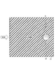
- FIG. 1 is a diagram showing the appearance of a reinforced concrete specimen 1 used in the present embodiment.
- the reinforced concrete specimen 1 includes a rectangular parallelepiped concrete 11 and a columnar reinforcing bar 12 vertically arranged inside the concrete 11.
- the concrete 11 has a crack 13 that is cracked in a direction perpendicular to the vertical direction of the reinforcing bar 12.
- a reinforced concrete specimen 1 be coated with a resin or the like on the concrete surface excluding the front exposed surface.
- a resin having low moisture permeability such as an epoxy resin is desirable.
- the thickness of the coating is desirably 1 mm or more.
- FIG. 2 is a diagram showing a configuration of the corrosion acceleration test apparatus 100 according to the present embodiment.
- the reinforced concrete specimen 1 shows a cross section cut along the depth direction of FIG.
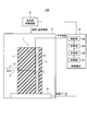
- the corrosion promotion test apparatus 100 includes a test tank 2, a moisture sensor 3, a weight measuring device 4, a temperature and humidity control device 5, And a terminal 6.
- the test tank 2 is a storage device for storing the reinforced concrete specimen 1. In order to keep the temperature and humidity in the tank constant, it is desirable that the test tank 2 has a structure capable of sealing the reinforced concrete specimen 1.
- the moisture sensor 3 is disposed beside the reinforcing bar 12 exposed from the cracked portion 13 of the reinforced concrete specimen 1 and, when detecting moisture inside the crack, sends a moisture detection signal indicating that moisture exists inside the crack to the control terminal 6. It has a function to output to The moisture sensor 3 is disposed adjacent to the reinforcing bar 12 in order to measure the amount of moisture on the exposed surface of the reinforcing bar 12. However, since the moisture sensor 3 may adversely affect the corrosion promotion of the reinforcing bar 12 when disposed adjacently, as shown in FIG. May be arranged at a position near the rebar 12 within a certain range.
- the casing material of the moisture sensor 3 is preferably ceramic or plastic so as not to affect the corrosion of the reinforcing bar 12.
- the weight measuring device 4 is disposed below the reinforced concrete specimen 1 inside the test tank 2, and has a function of measuring the weight of the reinforced concrete specimen 1 and transmitting the measured weight data to the control terminal 6.
- the temperature and humidity control device 5 has a function of controlling the temperature and humidity inside the test tank 2 based on a control signal from the control terminal 6.
- a control signal from the control terminal 6 For example, an air conditioner that can adjust temperature and humidity, a fan with a communication function, a sprayer with a communication function, a water supply and drainage device with a communication function, and the like are used.
- the temperature / humidity control device 5 corresponds to a “water supply / removal device” described in the claims.
- the control terminal 6 is electrically and physically connected to the moisture sensor 3, the weight measuring device 4, and the temperature / humidity controller 5, respectively, and as shown in FIG. 2, a receiving unit 61, a calculating unit 62, and a storing unit 63. And a control unit 64.
- the control terminal 6 is composed of, for example, a computer such as a personal computer.
- the receiver 61 has a function of receiving a moisture detection signal from the moisture sensor 3 and a weight data from the weight measuring device 4.
- the calculating unit 62 uses the weight data of the reinforced concrete specimen 1 measured by the weight measuring device 4 to perform an estimation calculation in which the increased weight of the reinforced concrete specimen 1 is regarded as the water content inside the crack, and stores it in the storage unit 63. Is provided.
- the storage unit 63 stores the moisture content inside the crack after the start of the test estimated and calculated by the calculation unit 62 as data on the moisture content inside the crack in association with the test time, and in order to repeatedly perform the wetting process and the drying process. It has a function of storing a set number of test cycles.
- the controller 64 transmits a control signal to the temperature / humidity controller 5 to control the temperature / humidity controller 5, so that the reinforced concrete specimen 1 in the test tank 2 supplies moisture to the inside of the crack. And a drying step of removing the moisture inside the crack and the moisture on the exposed surface of the reinforcing bar 12 are provided.
- control unit 64 starts the drying process by ending the wetting process when the moisture sensor 3 detects moisture after starting the wetting process, and when the moisture sensor 3 stops detecting moisture, It has a function to end the drying process and start the wetting process.
- control unit 64 ends the wetting step and starts the drying step, and starts the drying step.
- a function is provided to end the drying step and start the wetting step.
- control unit 64 refers to the data on the moisture content inside the crack stored in the storage unit 63 and detects a change in the slope of the change in the moisture content inside the crack, or detects the moisture content inside the crack (the reinforced concrete specimen 1).
- the wetting process is terminated and the drying process is started, and the water content inside the crack becomes saturated. It has a function to end the drying step and start the wetting step when the amount of water decreases.
- the control unit 64 determines only one of the presence or absence of a moisture detection signal from the moisture sensor 3, the change in the weight of the reinforced concrete specimen 1, and the change in the water content inside the crack estimated based on the weight of the reinforced concrete specimen 1. May be used, or two or more may be used in combination.
- FIG. 4 is a diagram showing a processing flow of the corrosion promotion test method.
- the corrosion of the reinforcing bars 12 included in the reinforced concrete specimen 1 is promoted by repeating the wetting step and the drying step on the reinforced concrete specimen 1 an arbitrary number of times.
- Step S101 the control terminal 6 determines the number of test cycles.
- the number of test cycles used for the test the number of test cycles stored in the storage unit 63 may be used, or the number of test cycles input by the user at the start of the test may be used.
- Step S102 wetting step
- the control terminal 6 uses the temperature and humidity control device 5 to humidify the inside of the test tank 2.
- the control terminal 6 may supply water to the test tank 2 by using a water supply / drainage device to immerse and discharge the reinforced concrete specimen 1 in water, or spray water to the cracked portion 13 using a sprayer. You may.
- the control terminal 6 may supply not the moisture but the salt water in order to further promote the corrosion of the reinforcing bar 12.
- Step S103 (wetting step); Next, using the weight data of the reinforced concrete specimen 1 transmitted from the weight measuring device 4 after the start of the test, the control terminal 6 performs an estimation calculation that regards the increased weight of the reinforced concrete specimen 1 as the moisture content inside the crack, It is stored in association with the test time.
- Step S104 (wetting step); Next, the control terminal 6 determines whether or not the moisture has filled the inside of the crack. If the moisture has filled the inside of the crack, the control terminal 6 terminates the water supply started in step S102 and proceeds to step S105, where the moisture is cracked. If the inside is not satisfied, the process returns to step S102 to continue supplying water.
- the control terminal 6 determines that the moisture has filled the inside of the crack when receiving the moisture detection signal from the moisture sensor 3.
- the control terminal 6 uses the slope of the weight change of the reinforced concrete specimen 1, when detecting the change in the slope of the weight change, the control terminal 6 determines that the moisture has filled the inside of the crack. I do. That is, the weight of the reinforced concrete specimen 1 increases at a constant increase rate from the start of the supply of moisture until the moisture saturates the inside of the crack, and the increase rate decreases after saturation. When the change in the inclination of the weight increase of the test piece 1 is detected, it is determined that the moisture has reached the surface of the reinforcing bar 12 and the moisture has filled the inside of the crack.
- a change in the slope of the weight change of the specimen 1 is detected, or when the moisture content inside the crack reaches the saturated moisture content based on the volume inside the crack (when moisture fills the inside of the crack), It is determined that the inside of the crack has been filled.
- the weight measuring device 4 when the crack width is 0.1 mm, the width and the depth of the reinforced concrete specimen 1 are 100 mm and 50 mm, respectively, when the weight of the reinforced concrete specimen 1 increases by 500 mg, or when the moisture inside the crack is increased. When the amount increases by 500 mg, it is determined that the moisture has reached the surface of the reinforcing bar 12 and the moisture has filled the inside of the crack.
- Step S105 drying step
- the control terminal 6 starts removing the moisture inside the crack and the moisture on the exposed surface of the reinforcing bar 12.
- the control terminal 6 uses the temperature and humidity control device 5 to dry the inside of the test tank 2.
- the control terminal 6 may blow wind to the cracked portion 13 using a fan.
- Step S106 drying step
- the control terminal 6 uses the weight data of the reinforced concrete specimen 1 transmitted from the weight measuring device 4 after the start of the test to calculate the reduced weight of the reinforced concrete specimen 1 to determine the moisture inside the crack. Estimate calculation to be regarded as quantity is performed and stored in association with the test time.
- Step S107 drying step
- the control terminal 6 determines whether or not the moisture has been removed from the inside of the crack. If the moisture has been removed from the inside of the crack, the process proceeds to step S108. If the moisture has not been removed from the inside of the crack, the process proceeds to step S105. Return to and continue removing water.
- the control terminal 6 stops receiving the moisture detection signal from the moisture sensor 3, it determines that the moisture has been removed from inside the crack.
- the control terminal 6 uses the inclination of the weight change of the reinforced concrete specimen 1, the control terminal 6 increases the weight of the reinforced concrete specimen 1 by the increased weight when the change in the inclination of the weight change of the reinforced concrete specimen 1 is detected. When the weight of the specimen 1 is reduced, it is determined that the moisture has been removed from the inside of the crack.
- the control terminal 6 determines whether the moisture content inside the crack decreases by the saturated moisture content. Then, it is determined that the water has been removed from the inside of the crack.
- Step S108 Finally, the control terminal 6 determines whether or not the number of execution cycles in which the test has been performed exceeds the number of test cycles. If the number of cycles has not been exceeded, the process returns to step S102.
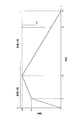
- FIG. 5 is a diagram showing an example of a change in weight of the reinforced concrete specimen 1.
- FIG. 5 shows the weight w2 after the change in the slope of the weight and the time t2.
- the time t1 After the time t1, if the wetting process is continued, the diffusion of moisture into the concrete proceeds, and the weight continues to increase. However, since the supply of water of the weight w1 or more is unnecessary, the timing when the weight increases to the weight w1 instead of the weight w2. Alternatively, by ending the wetting process at the time t1 instead of the time t2, the time relating to the wetting process can be optimized.
- the drying step it is necessary to reduce at least the increased weight w1.
- the moisture inside the crack and the moisture inside the concrete evaporate simultaneously from the exposed surface, so that it is necessary to remove the weight or the amount of moisture of w1 ⁇ w2 in order to remove the moisture inside the crack.
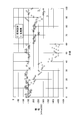
- FIG. 6 is a diagram showing the results of measuring the electric potential of the reinforcing bar 12 during and after corrosion.
- ⁇ indicates the prior art, and ⁇ indicates the present invention.
- the drying step (tank humidity: 0%) and the wetting step (tank humidity: 100%) were alternately repeated every 12 hours.
- the potential of the reinforcing bar 12 is measured using a corrosion determination device (ASTM-C876), the potential after 40 to 60 days is ⁇ 450 to ⁇ 350 mV vs. CSE in the case of the present invention, and ⁇ 100 to ⁇ 150 mV vs CSE in the case of the conventional technology. there were. From this measurement result, it can be seen that the time required for the present invention to decrease in potential is shorter than that of the related art. Therefore, it was shown that the reinforcing bar 12 was corroded in a short time according to the present invention.
- FIG. 7 is a diagram showing the potential measurement result of the reinforcing bar 12 when the reinforcing bar 12 is exposed to the air after the corrosion promotion test of the present invention is performed.
- the accelerated corrosion test showed that the lowered potential increased due to exposure to the atmosphere, and that the moisture stopped inside the crack was not sufficiently dried and removed during the exposure to the atmosphere, and as a result, the corrosion stopped.
- the corrosion promoting test apparatus 100 in the corrosion promotion test apparatus 100 that promotes corrosion of the reinforcing bars 12 included in the reinforced concrete specimen 1 having cracks, the corrosion promoting test apparatus 100 is disposed near the reinforcing bars 12 exposed from the cracked portions 13 of the concrete 11.
- a control terminal 6 that alternately and repeatedly performs a wetting step of supplying moisture to the water and a drying step of removing the moisture inside the crack and the moisture on the exposed surface of the reinforcing bar 12, and the control terminal 6 performs the wetting step.
- the wetting process is terminated. Since starting the drying process by, reducing the time of the accelerated corrosion test corroding reinforcing bars 12, the information that contributes to advance understanding of the state of deterioration of reinforced concrete structures due Corrosion after Cracking can be obtained in a short period of time.
- control terminal 6 can be realized by a computer and a program, and the program can be recorded on a recording medium or provided through a network.
Landscapes
- Life Sciences & Earth Sciences (AREA)
- Chemical & Material Sciences (AREA)
- Health & Medical Sciences (AREA)
- Immunology (AREA)
- Pathology (AREA)
- Physics & Mathematics (AREA)
- General Physics & Mathematics (AREA)
- General Health & Medical Sciences (AREA)
- Analytical Chemistry (AREA)
- Biochemistry (AREA)
- Ecology (AREA)
- Environmental & Geological Engineering (AREA)
- Biodiversity & Conservation Biology (AREA)
- Environmental Sciences (AREA)
- Crystallography & Structural Chemistry (AREA)
- Engineering & Computer Science (AREA)
- Food Science & Technology (AREA)
- Medicinal Chemistry (AREA)
- Testing Resistance To Weather, Investigating Materials By Mechanical Methods (AREA)
Abstract
ひび割れを有する鉄筋コンクリート供試体に含まれる鉄筋の腐食を促進させる。ひび割れを有する鉄筋コンクリート供試体1に含まれる鉄筋12の腐食を促進させる腐食促進試験装置100において、コンクリート11のひび割れ部13から露出した鉄筋12の傍に配置された水分センサ3と、鉄筋コンクリート供試体1の重量を計測する重量計測器4と、水分センサ3と重量計測器4とにそれぞれ接続され、温湿度制御装置5を制御することにより、ひび割れたひび内部に水分を供給する湿潤工程と、ひび内部の水分と鉄筋12の露出面の水分とを除去する乾燥工程と、を交互に繰り返し行う制御端末6と、を備え、制御端末6は、湿潤工程を開始した後、水分センサ3で水分を検知したとき、又は鉄筋コンクリート供試体1の重量変化の傾きの変化を検知したときに、湿潤工程を終了して乾燥工程を開始する。
Description
本発明は、ひび割れを有する鉄筋コンクリート供試体に含まれる鉄筋の腐食を促進させる技術に関する。
鉄筋コンクリートは、内部の鉄筋がコンクリートの強度を高める役割を持つことに加え、アルカリ性のコンクリートが鉄筋を覆うことで内部の鉄筋を防食する複合材料としても知られている。
一方、鉄筋コンクリートが所定環境に設置されると、酸素侵入により大気接触面からコンクリートの中性化が徐々に進行し、鉄筋の位置まで進行すると防食性能が失われ、コンクリート内部の鉄筋は、腐食開始状態となる。このことから、RC構造物等では、コンクリートの中性化により鉄筋の腐食が開始するまでの時間の長さによって、その供用期間が評価されている(非特許文献1)。
特にコンクリートにひび割れが生じると、コンクリート表面からのひび割れの深さに応じてコンクリートの中性化が進行することが報告されている(非特許文献2)。コンクリートのひび割れは、鉄筋コンクリートの構造に致命的な欠陥である反面、その予知予防は難しく、通常、ひび割れを確認次第速やかに補修又は更改を行う措置が採られている。ひび割れは目視点検により発見されるが、点検を行う時間間隔は対象構造物の数及び保守点検人員の稼働に大きく依存し、ひび割れ発生後の一定期間は放置されることが想定される。
そこで、現在では、ひび割れ発生後の鉄筋腐食による鉄筋コンクリート構造物の劣化状態を事前に把握することが求められている。
米澤、外5名、"コンクリートの中性化後における鉄筋の腐食速度に関する研究"、日本建築学会構造系論文集、第79巻、第704号、2014年10月、p.1405-p.1414
伊代田、外1名、"コンクリートのひび割れが中性化深さに及ぼす影響"、生産研究、50巻、9号、1998年9月、p.319-p.321
ひび割れ発生後の鉄筋腐食による鉄筋コンクリート構造物の劣化状態を事前に把握するためには、鉄筋コンクリート内部の鉄筋を短期間で腐食させる必要がある。しかし、ひび割れを有する鉄筋コンクリート供試体の鉄筋を短期間で腐食させる方法は指針化されておらず、鉄筋コンクリート供試体に特化した腐食促進試験方法及びその装置は存在していなかった。
本発明は、上記事情を鑑みてなされたものであり、ひび割れを有する鉄筋コンクリート供試体に含まれる鉄筋の腐食を促進させることを目的とする。
本発明の腐食促進試験方法は、ひび割れを有する鉄筋コンクリート供試体に含まれる鉄筋の腐食を促進させる腐食促進試験方法において、制御端末は、コンクリートのひび割れ部から露出した鉄筋の傍に配置された水分センサと、前記鉄筋コンクリート供試体の重量を計測する重量計測器と、にそれぞれ接続され、水分供給除去装置を制御することにより、ひび割れたひび内部に水分を供給する湿潤ステップと、前記湿潤ステップを開始した後、前記水分センサで水分を検知したとき、又は前記鉄筋コンクリート供試体の重量変化の傾きの変化を検知したときに、前記湿潤ステップを終了し、前記ひび内部の水分と前記鉄筋の露出面の水分とを除去する乾燥ステップと、を交互に繰り返し行う。
上記腐食促進試験方法において、前記制御端末は、前記乾燥ステップを開始した後、前記水分センサで水分が検知されなくなったとき、又は前記重量変化の傾きの変化を検知したときの増加重量分だけ前記鉄筋コンクリート供試体の重量が減少したときに、前記乾燥ステップを終了して前記湿潤ステップを開始する。
上記腐食促進試験方法において、前記制御端末は、前記鉄筋コンクリート供試体の増加重量を前記ひび内部の水分量とみなし、前記鉄筋コンクリート供試体の重量変化の傾きの変化の検知に代えて、前記ひび内部の水分量の変化の傾きの変化を検知したとき、又は前記ひび内部の水分量が前記ひび内部の体積に基づく飽和水分量に到達したときに、前記湿潤ステップを終了する。
上記腐食促進試験方法において、前記制御端末は、前記ひび内部の水分量が前記飽和水分量だけ減少したときに、前記乾燥ステップを終了する。
上記腐食促進試験方法において、前記湿潤ステップでは、前記鉄筋コンクリート供試体を水中に浸水させる、又は前記鉄筋コンクリート供試体に水分を噴霧する。
本発明の腐食促進試験装置は、ひび割れを有する鉄筋コンクリート供試体に含まれる鉄筋の腐食を促進させる腐食促進試験装置において、コンクリートのひび割れ部から露出した鉄筋の傍に配置された水分センサと、前記鉄筋コンクリート供試体の重量を計測する重量計測器と、前記水分センサと前記重量計測器とにそれぞれ接続され、水分供給除去装置を制御することにより、ひび割れたひび内部に水分を供給する湿潤工程と、前記ひび内部の水分と前記鉄筋の露出面の水分とを除去する乾燥工程と、を交互に繰り返し行う制御端末と、を備え、前記制御端末は、前記湿潤工程を開始した後、前記水分センサで水分を検知したとき、又は前記鉄筋コンクリート供試体の重量変化の傾きの変化を検知したときに、前記湿潤工程を終了して前記乾燥工程を開始する。
上記腐食促進試験装置において、前記制御端末は、前記乾燥工程を開始した後、前記水分センサで水分が検知されなくなったとき、又は前記重量変化の傾きの変化を検知したときの増加重量分だけ前記鉄筋コンクリート供試体の重量が減少したときに、前記乾燥工程を終了して前記湿潤工程を開始する。
上記腐食促進試験装置において、前記制御端末は、前記鉄筋コンクリート供試体の増加重量を前記ひび内部の水分量とみなし、前記鉄筋コンクリート供試体の重量変化の傾きの変化の検知に代えて、前記ひび内部の水分量の変化の傾きの変化を検知したとき、又は前記ひび内部の水分量が前記ひび内部の体積に基づく飽和水分量に到達したときに、前記湿潤工程を終了して前記乾燥工程を開始し、前記ひび内部の水分量が前記飽和水分量だけ減少したときに、前記乾燥工程を終了して前記湿潤工程を開始する。
本発明によれば、ひび割れを有する鉄筋コンクリート供試体に含まれる鉄筋の腐食を促進できる。
本発明は、ひび割れを有する鉄筋コンクリート供試体に含まれる鉄筋の腐食を促進させるため、コンクリートのひび内部に水分を供給する湿潤工程と、ひび内部の水分と鉄筋の露出面の水分とを除去する乾燥工程と、を繰り返すことを特徴とする。
ひび割れを有する鉄筋コンクリートの内部では、ひび割れた内壁のコンクリートが中性化し、ひびが鉄筋に到達している場合、鉄筋近傍も中性条件となる。環境内の水分はほぼ中性であることから、ひび内部に水分が侵入すると鉄筋の腐食が進行する。しかし、ひび内部に水分が一定期間滞留すると、腐食生成物や水分により酸素の拡散が抑止され、又はコンクリートからの水酸化カルシウムの拡散により鉄筋近傍がアルカリ化するので、腐食の進行が停止してしまう。それ故、ひび割れた位置の鉄筋の腐食を促進させるためには、ひび内部の水分のアルカリ化を抑止し、又は酸素を供給することが必要である。
そこで本発明は、ひび内部の水分のアルカリ化を抑止し、かつ、酸素の供給を促進するため、ひび内部の水分の滞留を妨げるようにする。つまり、ひび割れを有する鉄筋コンクリート供試体に対して乾燥工程を付与することで、ひび内部の水分を除去する。そして、その後に再度水分を侵入させ、再び乾燥させることを繰り返す。その際、ひび内部の水分量を推定して当該ひび内部の水分量が飽和又は消滅したことを検知したタイミング、又は水分センサでひび割れた内部の水分の有無を検知したタイミングで湿潤工程と乾燥工程とを交互に切り替えることにより、腐食促進試験の時間短縮を図る。
以下、本発明を実施する一実施の形態について図面を用いて説明する。
図1は、本実施形態で用いる鉄筋コンクリート供試体1の外観を示す図である。鉄筋コンクリート供試体1は、図1に示すように、直方体状のコンクリート11と、コンクリート11の内部に垂直方向に配置された円柱状の鉄筋12と、を備えて構成される。コンクリート11には、鉄筋12の上下方向に対して垂直方向にひび割れたひび割れ部13が形成されている。
このような鉄筋コンクリート供試体1は、実環境内の鉄筋コンクリート構造物を模擬するため、正面の露出面を除くコンクリート表面を樹脂等で被覆することが望ましい。被覆に用いる樹脂の種類は、例えばエポキシ樹脂等、水分の透過性が低いものが望ましい。被覆の厚さは、1mm以上あることが望ましい。
図2は、本実施形態に係る腐食促進試験装置100の構成を示す図である。鉄筋コンクリート供試体1は、図1の奥行き方向に沿って切断した断面を示している。図2に示すように、腐食促進試験装置100は、図1に示した鉄筋コンクリート供試体1に加え、試験槽2と、水分センサ3と、重量計測器4と、温湿度制御装置5と、制御端末6と、を備えて構成される。
試験槽2は、鉄筋コンクリート供試体1を格納する格納装置である。槽内の温度及び湿度を一定に維持するため、試験槽2は、鉄筋コンクリート供試体1を密閉できる構造が望ましい。
水分センサ3は、鉄筋コンクリート供試体1のひび割れ部13から露出した鉄筋12の傍に配置され、ひび内部の水分を検知したときに、ひび内部に水分があることを示す水分検知信号を制御端末6へ出力する機能を備える。水分センサ3は、鉄筋12の露出面の水分量を測定するために鉄筋12に隣接配置されるが、隣接配置すると鉄筋12の腐食促進に悪影響を与える可能性があるので、図3に示すように鉄筋12から一定範囲内の近傍位置に配置してもよい。なお、水分センサ3の筐体材質は、鉄筋12の腐食に影響を与えないように、セラミック又はプラスチックであることが望ましい。
重量計測器4は、試験槽2の内部で鉄筋コンクリート供試体1の下に配置され、鉄筋コンクリート供試体1の重量を計測し、計測した重量データを制御端末6へ送信する機能を備える。
温湿度制御装置5は、制御端末6からの制御信号に基づき、試験槽2の内部の温度と湿度をそれぞれ制御する機能を備える。例えば、温度と湿度をそれぞれ調整可能なエアコン、通信機能付きの扇風機、通信機能付きの噴霧器、通信機能付きの給水排水装置等を用いる。温湿度制御装置5は、特許請求の範囲に記載された「水分供給除去装置」に相当する。
制御端末6は、水分センサ3、重量計測器4、及び温湿度制御装置5にそれぞれ電気的物理的に接続され、図2に示すように、受信部61と、計算部62と、記憶部63と、制御部64と、を備えて構成される。制御端末6は、例えばパソコン等のコンピュータで構成される。
受信部61は、水分センサ3から水分検知信号、及び重量計測器4から重量データをそれぞれ受信する機能を備える。
計算部62は、重量計測器4で計測された鉄筋コンクリート供試体1の重量データを用いて、鉄筋コンクリート供試体1の増加重量をひび内部の水分量とみなす推定計算を行い記憶部63に記憶させる機能を備える。
記憶部63は、計算部62で推定計算された試験開始後のひび内部の水分量を試験時刻に関連付けてひび内部水分量データとして記憶するとともに、湿潤工程と乾燥工程とを繰り返し行うために予め設定された任意の試験サイクル数を記憶する機能を備える。
制御部64は、温湿度制御装置5に制御信号を送信して温湿度制御装置5を制御することにより、試験槽2内の鉄筋コンクリート供試体1に対して、ひび内部に水分を供給する湿潤工程と、ひび内部の水分と鉄筋12の露出面の水分とを除去する乾燥工程と、を交互に繰り返し行う機能を備える。
また、制御部64は、湿潤工程を開始した後、水分センサ3で水分を検知したときに、湿潤工程を終了して乾燥工程を開始し、水分センサ3で水分が検知されなくなったときに、乾燥工程を終了して湿潤工程を開始する機能を備える。
また、制御部64は、湿潤工程を開始した後、鉄筋コンクリート供試体1の重量変化の傾きの変化を検知したときに、湿潤工程を終了して乾燥工程を開始し、乾燥工程を開始した後、鉄筋コンクリート供試体1の重量変化の傾きの変化を検知したときの増加重量分だけ鉄筋コンクリート供試体1の重量が減少したときに、乾燥工程を終了して湿潤工程を開始する機能を備える。
また、制御部64は、記憶部63に記憶されたひび内部水分量データを参照し、ひび内部の水分量の変化の傾きの変化を検知したとき、又はひび内部の水分量(鉄筋コンクリート供試体1の重量変化から推定計算されたひび内部の水分量)がひび内部の体積に基づく飽和水分量に到達したときに、湿潤工程を終了して乾燥工程を開始し、ひび内部の水分量が当該飽和水分量だけ減少したときに、乾燥工程を終了して湿潤工程を開始する機能を備える。
なお、制御部64は、水分センサ3からの水分検知信号の有無、鉄筋コンクリート供試体1の重量変化、鉄筋コンクリート供試体1の重量に基づき推定したひび内部の水分量変化のうち、いずれか1つのみを用いてもよいし、2つ以上を組み合わせて用いてもよい。
次に、腐食促進試験装置100で行う腐食促進試験方法について説明する。図4は、腐食促進試験方法の処理フローを示す図である。本実施形態では、鉄筋コンクリート供試体1に対して湿潤工程と乾燥工程とを任意の回数繰り返すことで、鉄筋コンクリート供試体1に含まれる鉄筋12の腐食を促進する。
ステップS101;
まず、制御端末6は、試験サイクル数を決定する。試験に用いる試験サイクル数は、記憶部63に記憶された試験サイクル数を用いてもよいし、試験開始時にユーザが入力した試験サイクル数を用いてもよい。
まず、制御端末6は、試験サイクル数を決定する。試験に用いる試験サイクル数は、記憶部63に記憶された試験サイクル数を用いてもよいし、試験開始時にユーザが入力した試験サイクル数を用いてもよい。
ステップS102(湿潤工程);
制御端末6は、鉄筋コンクリート供試体1が初めて大気環境に放置されている場合、比較的乾燥した状態にあるので、鉄筋コンクリート供試体1に水分の供給を開始する。例えば、制御端末6は、温湿度制御装置5を用いて試験槽2の内部を加湿する。その他、制御端末6は、給水排水装置を用いて試験槽2に水を供給して鉄筋コンクリート供試体1を水中に浸水させ排出してもよいし、噴霧器を用いてひび割れ部13に水分を噴霧してもよい。制御端末6は、鉄筋12の腐食を更に促進させるため、水分ではなく塩水を供給してもよい。
制御端末6は、鉄筋コンクリート供試体1が初めて大気環境に放置されている場合、比較的乾燥した状態にあるので、鉄筋コンクリート供試体1に水分の供給を開始する。例えば、制御端末6は、温湿度制御装置5を用いて試験槽2の内部を加湿する。その他、制御端末6は、給水排水装置を用いて試験槽2に水を供給して鉄筋コンクリート供試体1を水中に浸水させ排出してもよいし、噴霧器を用いてひび割れ部13に水分を噴霧してもよい。制御端末6は、鉄筋12の腐食を更に促進させるため、水分ではなく塩水を供給してもよい。
ステップS103(湿潤工程);
次に、制御端末6は、試験開始後に重量計測器4から送信される鉄筋コンクリート供試体1の重量データを用いて、鉄筋コンクリート供試体1の増加重量をひび内部の水分量とみなす推定計算を行い、試験時刻に関連付けて記憶する。
次に、制御端末6は、試験開始後に重量計測器4から送信される鉄筋コンクリート供試体1の重量データを用いて、鉄筋コンクリート供試体1の増加重量をひび内部の水分量とみなす推定計算を行い、試験時刻に関連付けて記憶する。
ステップS104(湿潤工程);
次に、制御端末6は、水分がひび内部を満たしたか否かを判定し、水分がひび内部を満たした場合、ステップS102で開始した水分の給水を終了してステップS105へ進み、水分がひび内部を満たしていない場合、ステップS102へ戻り水分の給水を継続する。
次に、制御端末6は、水分がひび内部を満たしたか否かを判定し、水分がひび内部を満たした場合、ステップS102で開始した水分の給水を終了してステップS105へ進み、水分がひび内部を満たしていない場合、ステップS102へ戻り水分の給水を継続する。
原理的には、鉄筋12の表面に水分が到達した時点で腐食が生じることから、鉄筋12の表面に水分が到達した時点を湿潤工程終了のタイミングとする。以下、その具体例について説明する。
例えば、水分センサ3を用いる場合、制御端末6は、水分センサ3から水分検知信号を受信したときに、水分がひび内部を満たしたと判定する。
重量計測器4を用いる場合、制御端末6は、鉄筋コンクリート供試体1の重量変化の傾きを用いる場合であれば、その重量変化の傾きの変化を検知したときに、水分がひび内部を満たしたと判定する。つまり、鉄筋コンクリート供試体1の重量は、水分の供給を開始してから水分がひび内部を飽和するまで一定の増加比率で増加し、当該増加比率は飽和後に低下するので、制御端末6は、鉄筋コンクリート供試体1の重量増加の傾きの変化を検知したときに、鉄筋12の表面に水分が到達し、水分がひび内部を満たしたと判定する。
また、同様に重量計測器4を用いる場合において、ステップS103で推定計算したひび内部の水分量を用いる場合であれば、制御端末6は、ひび内部の水分量の変化の傾きの変化(=鉄筋コンクリート供試体1の重量変化の傾きの変化)を検知したとき、又はひび内部の水分量がひび内部の体積に基づく飽和水分量に到達したとき(水分がひび内部を充填したとき)に、水分がひび内部を満たしたと判定する。
重量計測器4を用いた場合、例えば、ひび幅0.1mm、鉄筋コンクリート供試体1の横幅と奥行がそれぞれ100mm,50mmの場合、鉄筋コンクリート供試体1の重量が500mg増加したとき、又はひび内部の水分量が500mg増加したときに、鉄筋12の表面に水分が到達し、水分がひび内部を満たしたと判定する。
ステップS105(乾燥工程);
その後、制御端末6は、ひび内部の水分と鉄筋12の露出面の水分の除去を開始する。例えば、制御端末6は、温湿度制御装置5を用いて試験槽2の内部を乾燥させる。その他、制御端末6は、扇風機を用いてひび割れ部13に風をあててもよい。
その後、制御端末6は、ひび内部の水分と鉄筋12の露出面の水分の除去を開始する。例えば、制御端末6は、温湿度制御装置5を用いて試験槽2の内部を乾燥させる。その他、制御端末6は、扇風機を用いてひび割れ部13に風をあててもよい。
ステップS106(乾燥工程);
次に、制御端末6は、ステップS103と同様に、試験開始後に重量計測器4から送信される鉄筋コンクリート供試体1の重量データを用いて、鉄筋コンクリート供試体1の減少後の重量をひび内部の水分量とみなす推定計算を行い、試験時刻に関連付けて記憶する。
次に、制御端末6は、ステップS103と同様に、試験開始後に重量計測器4から送信される鉄筋コンクリート供試体1の重量データを用いて、鉄筋コンクリート供試体1の減少後の重量をひび内部の水分量とみなす推定計算を行い、試験時刻に関連付けて記憶する。
ステップS107(乾燥工程);
次に、制御端末6は、水分がひび内部から除去されたか否かを判定し、水分がひび内部から除去された場合、ステップS108へ進み、水分がひび内部から除去されていない場合、ステップS105へ戻り水分の除去を継続する。
次に、制御端末6は、水分がひび内部から除去されたか否かを判定し、水分がひび内部から除去された場合、ステップS108へ進み、水分がひび内部から除去されていない場合、ステップS105へ戻り水分の除去を継続する。
例えば、水分センサ3を用いる場合、制御端末6は、水分センサ3から水分検知信号を受信しなくなったときに、水分がひび内部から除去されたと判定する。
重量計測器4を用いる場合、制御端末6は、鉄筋コンクリート供試体1の重量変化の傾きを用いる場合であれば、鉄筋コンクリート供試体1の重量変化の傾きの変化を検知したときの増加重量分だけ鉄筋コンクリート供試体1の重量が減少したときに、水分がひび内部から除去されたと判定する。
また、同様に重量計測器4を用いる場合において、ステップS106で推定計算したひび内部の水分量を用いる場合であれば、制御端末6は、ひび内部の水分量が上記飽和水分量だけ減少したときに、水分がひび内部から除去されたと判定する。
ステップS108;
最後に、制御端末6は、試験を行った実施サイクル数が試験サイクル数を超えたか否かを判定し、実施サイクル数が試験サイクル数を超えた場合、処理を終了し、実施サイクル数が試験サイクル数を超えていない場合、ステップS102へ戻る。
最後に、制御端末6は、試験を行った実施サイクル数が試験サイクル数を超えたか否かを判定し、実施サイクル数が試験サイクル数を超えた場合、処理を終了し、実施サイクル数が試験サイクル数を超えていない場合、ステップS102へ戻る。
図5は、鉄筋コンクリート供試体1の重量変化の例を示す図である。
鉄筋コンクリート供試体1に水分が侵入する場合、ひび内部への水分侵入は速やかに進む一方、ひび内部が水分で満ちた後は、コンクリートへの拡散が律速となり、重量変化は緩やかになる。それ故、乾燥状態の鉄筋コンクリート供試体1に塩水噴霧、加湿、溶液浸漬等を行い、鉄筋コンクリート供試体1の増加重量を測定し、重量変化の傾きの変化を検知した時刻t1の重量w1をひび内の飽和水分量とする。重量変化の傾きの変化を検知する必要があるので、図5には、重量の傾きの変化後の重量w2とその時刻t2も記載している。時刻t1の後、湿潤工程を継続するとコンクリート内部への水分の拡散が進行して重量増加が継続するが、重量w1以上の水分供給は不要なので、重量が重量w2ではなく重量w1まで増加したタイミング、又は時刻が時刻t2ではなく時刻t1のタイミングで湿潤工程を終了することで、湿潤工程に係る時間を最適化できる。
また、乾燥工程においては、少なくとも重量w1の増加重量分を減少させる必要がある。ただし、乾燥工程では、ひび内部の水分とコンクリート内部の水分が露出面から同時に蒸散するので、ひび内部の水分を除去するにはw1≦w2の重量又は水分量を除去する必要があり、時間を用いる場合にはt3≦t4とする必要がある。なお、湿潤工程の終了時刻を時刻t2ではなく時刻t1、又は湿潤工程での増加重量を重量w2ではなく重量w1とした場合、乾燥工程の終了時刻を時刻t3又は減少重量を重量w1として乾燥工程を設定することで、乾湿工程を最適化できる。
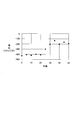
図6は、腐食中及び腐食後の鉄筋12の電位測定結果を示す図である。□は従来技術を示し、◇は本発明を示す。乾燥工程(槽内湿度:0%)と湿潤工程(槽内湿度:100%)とを12時間ごとに交互に繰り返し行った。腐食判定装置(ASTM-C876)を用いて鉄筋12の電位を測定すると、40~60日経過時の電位は、本発明の場合-450~-350mVvs CSE、従来技術の場合-100~-150mVvsCSEであった。この測定結果より、本発明の方が従来技術よりも電位低下までの時間が短いことが分かる。それ故、本発明により鉄筋12が短時間で腐食したことが示された。
図7は、本発明の腐食促進試験を実施した後、鉄筋12を大気暴露したときの鉄筋12の電位測定結果を示す図である。腐食促進試験により、低下していた電位が大気暴露により上昇しており、大気暴露時にはひび内部の水分が十分に乾燥除去されず滞留した結果、腐食が停止することが示された。
以上より、本実施形態によれば、ひび割れを有する鉄筋コンクリート供試体1に含まれる鉄筋12の腐食を促進させる腐食促進試験装置100において、コンクリート11のひび割れ部13から露出した鉄筋12の傍に配置された水分センサ3と、鉄筋コンクリート供試体1の重量を計測する重量計測器4と、水分センサ3と重量計測器4とにそれぞれ接続され、温湿度制御装置5を制御することにより、ひび割れたひび内部に水分を供給する湿潤工程と、ひび内部の水分と鉄筋12の露出面の水分とを除去する乾燥工程と、を交互に繰り返し行う制御端末6と、を備え、制御端末6は、湿潤工程を開始した後、水分センサ3で水分を検知したとき、又は鉄筋コンクリート供試体1の重量変化の傾きの変化を検知したときに、湿潤工程を終了して乾燥工程を開始するので、鉄筋12を腐食させる腐食促進試験に係る時間を短縮でき、ひび割れ発生後の鉄筋腐食による鉄筋コンクリート構造物の劣化状態の事前把握に資する情報を短期間で取得できる。
最後に、制御端末6は、コンピュータとプログラムによっても実現でき、プログラムを記録媒体に記録することも、ネットワークを通して提供することも可能である。
1…鉄筋コンクリート供試体
11…コンクリート
12…鉄筋
13…ひび割れ部
2…試験槽
3…水分センサ
4…重量計測器
5…温湿度制御装置
6…制御端末
61…受信部
62…計算部
63…記憶部
64…制御部
11…コンクリート
12…鉄筋
13…ひび割れ部
2…試験槽
3…水分センサ
4…重量計測器
5…温湿度制御装置
6…制御端末
61…受信部
62…計算部
63…記憶部
64…制御部
Claims (8)
- ひび割れを有する鉄筋コンクリート供試体に含まれる鉄筋の腐食を促進させる腐食促進試験方法において、
制御端末は、コンクリートのひび割れ部から露出した鉄筋の傍に配置された水分センサと、前記鉄筋コンクリート供試体の重量を計測する重量計測器と、にそれぞれ接続され、水分供給除去装置を制御することにより、
ひび割れたひび内部に水分を供給する湿潤ステップと、
前記湿潤ステップを開始した後、前記水分センサで水分を検知したとき、又は前記鉄筋コンクリート供試体の重量変化の傾きの変化を検知したときに、前記湿潤ステップを終了し、前記ひび内部の水分と前記鉄筋の露出面の水分とを除去する乾燥ステップと、
を交互に繰り返し行うことを特徴とする腐食促進試験方法。 - 前記制御端末は、
前記乾燥ステップを開始した後、前記水分センサで水分が検知されなくなったとき、又は前記重量変化の傾きの変化を検知したときの増加重量分だけ前記鉄筋コンクリート供試体の重量が減少したときに、前記乾燥ステップを終了して前記湿潤ステップを開始することを特徴とする請求項1に記載の腐食促進試験方法。 - 前記制御端末は、
前記鉄筋コンクリート供試体の増加重量を前記ひび内部の水分量とみなし、前記鉄筋コンクリート供試体の重量変化の傾きの変化の検知に代えて、前記ひび内部の水分量の変化の傾きの変化を検知したとき、又は前記ひび内部の水分量が前記ひび内部の体積に基づく飽和水分量に到達したときに、前記湿潤ステップを終了することを特徴とする請求項1に記載の腐食促進試験方法。 - 前記制御端末は、
前記ひび内部の水分量が前記飽和水分量だけ減少したときに、前記乾燥ステップを終了することを特徴とする請求項3に記載の腐食促進試験方法。 - 前記湿潤ステップでは、
前記鉄筋コンクリート供試体を水中に浸水させる、又は前記鉄筋コンクリート供試体に水分を噴霧することを特徴とする請求項1乃至4のいずれかに記載の腐食促進試験方法。 - ひび割れを有する鉄筋コンクリート供試体に含まれる鉄筋の腐食を促進させる腐食促進試験装置において、
コンクリートのひび割れ部から露出した鉄筋の傍に配置された水分センサと、
前記鉄筋コンクリート供試体の重量を計測する重量計測器と、
前記水分センサと前記重量計測器とにそれぞれ接続され、水分供給除去装置を制御することにより、ひび割れたひび内部に水分を供給する湿潤工程と、前記ひび内部の水分と前記鉄筋の露出面の水分とを除去する乾燥工程と、を交互に繰り返し行う制御端末と、を備え、
前記制御端末は、
前記湿潤工程を開始した後、前記水分センサで水分を検知したとき、又は前記鉄筋コンクリート供試体の重量変化の傾きの変化を検知したときに、前記湿潤工程を終了して前記乾燥工程を開始することを特徴とする腐食促進試験装置。 - 前記制御端末は、
前記乾燥工程を開始した後、前記水分センサで水分が検知されなくなったとき、又は前記重量変化の傾きの変化を検知したときの増加重量分だけ前記鉄筋コンクリート供試体の重量が減少したときに、前記乾燥工程を終了して前記湿潤工程を開始することを特徴とする請求項6に記載の腐食促進試験装置。 - 前記制御端末は、
前記鉄筋コンクリート供試体の増加重量を前記ひび内部の水分量とみなし、前記鉄筋コンクリート供試体の重量変化の傾きの変化の検知に代えて、前記ひび内部の水分量の変化の傾きの変化を検知したとき、又は前記ひび内部の水分量が前記ひび内部の体積に基づく飽和水分量に到達したときに、前記湿潤工程を終了して前記乾燥工程を開始し、前記ひび内部の水分量が前記飽和水分量だけ減少したときに、前記乾燥工程を終了して前記湿潤工程を開始することを特徴とする請求項6に記載の腐食促進試験装置。
Priority Applications (1)
| Application Number | Priority Date | Filing Date | Title |
|---|---|---|---|
| US17/265,106 US11867609B2 (en) | 2018-08-06 | 2019-06-28 | Method and apparatus for accelerated corrosion testing |
Applications Claiming Priority (2)
| Application Number | Priority Date | Filing Date | Title |
|---|---|---|---|
| JP2018-147517 | 2018-08-06 | ||
| JP2018147517A JP6880413B2 (ja) | 2018-08-06 | 2018-08-06 | 腐食促進試験方法及び腐食促進試験装置 |
Publications (1)
| Publication Number | Publication Date |
|---|---|
| WO2020031546A1 true WO2020031546A1 (ja) | 2020-02-13 |
Family
ID=69414610
Family Applications (1)
| Application Number | Title | Priority Date | Filing Date |
|---|---|---|---|
| PCT/JP2019/025922 Ceased WO2020031546A1 (ja) | 2018-08-06 | 2019-06-28 | 腐食促進試験方法及び腐食促進試験装置 |
Country Status (3)
| Country | Link |
|---|---|
| US (1) | US11867609B2 (ja) |
| JP (1) | JP6880413B2 (ja) |
| WO (1) | WO2020031546A1 (ja) |
Citations (3)
| Publication number | Priority date | Publication date | Assignee | Title |
|---|---|---|---|---|
| JPH03183740A (ja) * | 1989-12-12 | 1991-08-09 | Nippon Steel Corp | コンクリート劣化防止用耐塩鉄筋 |
| JP2012145330A (ja) * | 2009-10-07 | 2012-08-02 | Taiheiyo Cement Corp | 腐食センサ装置、腐食センサ装置の製造方法、腐食検出方法、センサおよびセンサの製造方法 |
| JP2013044529A (ja) * | 2011-08-22 | 2013-03-04 | Ube Ind Ltd | 鉄筋腐食促進試験方法 |
Family Cites Families (3)
| Publication number | Priority date | Publication date | Assignee | Title |
|---|---|---|---|---|
| EP1148329A1 (de) * | 2000-04-19 | 2001-10-24 | Ciments Vigier SA | Vorrichtung zur Bestimmung des Wassergehalts von Frischbeton |
| US9267875B2 (en) * | 2013-11-21 | 2016-02-23 | Medtronic Minimed, Inc. | Accelerated life testing device and method |
| CN204491639U (zh) * | 2015-02-11 | 2015-07-22 | 中铁二十五局集团第一工程有限公司 | 一种防止渗透、防止侵蚀的海上围堰 |
-
2018
- 2018-08-06 JP JP2018147517A patent/JP6880413B2/ja active Active
-
2019
- 2019-06-28 US US17/265,106 patent/US11867609B2/en active Active
- 2019-06-28 WO PCT/JP2019/025922 patent/WO2020031546A1/ja not_active Ceased
Patent Citations (3)
| Publication number | Priority date | Publication date | Assignee | Title |
|---|---|---|---|---|
| JPH03183740A (ja) * | 1989-12-12 | 1991-08-09 | Nippon Steel Corp | コンクリート劣化防止用耐塩鉄筋 |
| JP2012145330A (ja) * | 2009-10-07 | 2012-08-02 | Taiheiyo Cement Corp | 腐食センサ装置、腐食センサ装置の製造方法、腐食検出方法、センサおよびセンサの製造方法 |
| JP2013044529A (ja) * | 2011-08-22 | 2013-03-04 | Ube Ind Ltd | 鉄筋腐食促進試験方法 |
Also Published As
| Publication number | Publication date |
|---|---|
| US11867609B2 (en) | 2024-01-09 |
| JP2020024100A (ja) | 2020-02-13 |
| JP6880413B2 (ja) | 2021-06-02 |
| US20210318228A1 (en) | 2021-10-14 |
Similar Documents
| Publication | Publication Date | Title |
|---|---|---|
| JP6626285B2 (ja) | 腐食状態予測方法 | |
| Parrott | A study of carbonation-induced corrosion | |
| JP6734705B2 (ja) | 測定方法および推定方法 | |
| Vyrides et al. | Efficiency of amino alcohols as corrosion inhibitors in reinforced concrete | |
| CN105036695B (zh) | 钢筋混凝土结构体的修复防护层及其施工方法 | |
| Vedalakshmi et al. | Analysis of the electrochemical phenomenon at the rebar–concrete interface using the electrochemical impedance spectroscopic technique | |
| JP6574331B2 (ja) | 腐食センサおよび腐食検出方法 | |
| Tang et al. | Experiences from RILEM TC 235-CTC in recommending a test method for chloride threshold values in concrete | |
| JP5875171B2 (ja) | コンクリート構造物用腐食環境検知センサ | |
| JP2020024100A (ja) | 腐食促進試験方法及び腐食促進試験装置 | |
| Dauji | Reinforcement corrosion in coastal and marine concrete: A review | |
| JP7364968B2 (ja) | 湿度調整装置及び湿度調整方法 | |
| Olajide et al. | Review on the Role of Moisture and Temperature in Alkali-Silica Reaction (ASR) | |
| JP4374519B2 (ja) | 構造体コンクリートの強度評価方法 | |
| Elinwa et al. | Sawdust ash as an inhibitor for reinforcement corrosion in concrete | |
| JP5422791B2 (ja) | コンクリート構造物の補修方法及びコンクリート構造物の鉄筋腐食防止構造 | |
| Berke et al. | Organofunctional silane inhibitor surface treatment of concrete for corrosion | |
| Hoque et al. | Chloride transport accelerated via modest electromigration as a means to initiate corrosion of the steel reinforcement | |
| JP7079051B2 (ja) | 腐食推定方法および推定方法 | |
| JP2014106003A (ja) | 水硬性材料のひずみ測定方法 | |
| Buenfeld et al. | Impedance spectroscopy monitoring of a polyurethane coating on mortar exposed to NaCl solution | |
| Berke et al. | Protective Surface Treatments for New and Existing Steel Reinforced Concrete to Mitigate Corrosion | |
| Zhang et al. | Influence of water repellent surface impregnation of cracked SHCC on steel corrosion | |
| Vandecruys et al. | Experimental study of vibration-based monitoring of locally corroding reinforced concrete beams | |
| BEUSHAUSEN et al. | HYDROPHOBIC TREATMENT FOR CONTROL OF DETERIORATION IN REINFORCED CONCRETE STRUCTURES |
Legal Events
| Date | Code | Title | Description |
|---|---|---|---|
| 121 | Ep: the epo has been informed by wipo that ep was designated in this application |
Ref document number: 19848420 Country of ref document: EP Kind code of ref document: A1 |
|
| NENP | Non-entry into the national phase |
Ref country code: DE |
|
| 122 | Ep: pct application non-entry in european phase |
Ref document number: 19848420 Country of ref document: EP Kind code of ref document: A1 |