WO2020031336A1 - 受信装置、タイミング検出装置およびタイミング検出方法 - Google Patents
受信装置、タイミング検出装置およびタイミング検出方法 Download PDFInfo
- Publication number
- WO2020031336A1 WO2020031336A1 PCT/JP2018/029953 JP2018029953W WO2020031336A1 WO 2020031336 A1 WO2020031336 A1 WO 2020031336A1 JP 2018029953 W JP2018029953 W JP 2018029953W WO 2020031336 A1 WO2020031336 A1 WO 2020031336A1
- Authority
- WO
- WIPO (PCT)
- Prior art keywords
- correlation
- value
- unit
- power value
- timing
- Prior art date
- Legal status (The legal status is an assumption and is not a legal conclusion. Google has not performed a legal analysis and makes no representation as to the accuracy of the status listed.)
- Ceased
Links
Images





Classifications
-
- H—ELECTRICITY
- H04—ELECTRIC COMMUNICATION TECHNIQUE
- H04B—TRANSMISSION
- H04B1/00—Details of transmission systems, not covered by a single one of groups H04B3/00 - H04B13/00; Details of transmission systems not characterised by the medium used for transmission
- H04B1/69—Spread spectrum techniques
- H04B1/707—Spread spectrum techniques using direct sequence modulation
- H04B1/7073—Synchronisation aspects
Definitions
- the present invention relates to a receiving device, a timing detecting device, and a timing detecting method for directly receiving a signal subjected to spread spectrum.
- a transmitter spreads a signal over a wide band by multiplying a modulated signal by a spreading code, and transmits the spread signal to a receiver.
- the receiver performs despreading by multiplying the received signal by the same spreading code as the spreading code used in the transmitter, and demodulates the despread received signal.
- it is necessary to perform initial acquisition for estimating the spread code timing, that is, the timing at which the transmitter multiplies the modulated signal by the spread code, and multiply the received signal by the spread code at the estimated timing. There is.
- Non-Patent Document 1 which is an example of a conventional initial acquisition method
- a matched filter (Matched Filter) that multiplies a received signal by a spreading code is divided into a plurality of segments, and the positions of signals output from each segment are compared.
- Detect phase difference Furthermore, the detected phase difference is averaged with the phase difference detected in the symbol received in the past, and the spread sequence timing, which is the spread code timing, is estimated based on the averaged phase difference.
- the initial acquisition can be completed accurately and in a short time.
- the resistance to the frequency offset is increased by increasing the number of divisions of the matched filter, but the side lobe of the correlation value appears at the sample timing other than the spread sequence timing. Furthermore, sidelobes appear not only due to an increase in the number of divisions but also due to oversampling. Therefore, there is a high possibility that the timing at which the side lobe exists is erroneously determined as the spread sequence timing, and the determination accuracy deteriorates.
- the present invention has been made in view of the above, and an object of the present invention is to provide a receiving apparatus capable of improving the accuracy of estimating a spreading code timing.
- a receiving apparatus multiplies a received signal subjected to direct spectrum spreading by a complex conjugate of a spreading code used for direct spectrum spreading.
- a spread code multiplying unit that generates a correlation value sequence, and a correlation addition value is generated by adding each correlation value of the correlation value sequence generated each time the spreading code multiplication unit performs multiplication, and the power value of the correlation addition value is used.
- a first correlation power calculator for calculating a certain first correlation power value is provided.
- the receiving apparatus divides the correlation value sequence into a plurality of blocks, generates a partial correlation value by adding each correlation value in the block, and obtains a power value of the partial correlation value for each block.
- a second correlation power calculator for adding the obtained power values together to calculate a second correlation power value, and a transmission source of the received signal based on the first correlation power value and the second correlation power value.
- a timing detector for detecting a timing at which the transmitting device of (1) multiplies a transmission signal by a spreading code in direct spectrum spreading.
- the receiving apparatus has an effect that the estimation accuracy of the spread code timing can be improved.
- FIG. 3 is a diagram illustrating a configuration example of a transmitter according to the first embodiment; Flowchart showing an example of the operation of the transmitter according to the first embodiment
- FIG. 3 is a diagram illustrating a frame configuration of a signal transmitted by the transmitter according to the first embodiment;
- FIG. 3 is a diagram illustrating a configuration example of a receiver according to the first embodiment.
- 5 is a flowchart illustrating an example of the operation of the receiver according to the first embodiment.
- FIG. 3 is a diagram illustrating a configuration example of an initial capturing unit according to the first embodiment; 5 is a flowchart illustrating an example of an operation of the initial capturing unit according to the first embodiment.
- FIG. 3 is a diagram illustrating a configuration example of an initial capturing unit according to the first embodiment
- 5 is a flowchart illustrating an example of an operation of the initial capturing unit according to the first embodiment.
- FIG. 3 is a diagram illustrating a configuration example of a spreading code multiplication unit according to the first embodiment; The figure which shows an example of the 2nd correlation power value for one period transferred to the sample synthesis part. The figure which shows an example of the sample combined power value for one period which the sample combining section outputs. The figure which shows an example of the 1st correlation electric power value which a 1st correlation electric power calculation part outputs. The figure which shows an example of the sample combined power value output by the sample combining section.
- FIG. 7 is a diagram for explaining the reason why the second correlation power value calculated by the second correlation power calculation unit is strong in frequency offset resistance.
- FIG. 4 is a diagram showing a modification of the initial capturing unit included in the receiver according to the first embodiment.
- FIG. 2 is a diagram illustrating a processing circuit that realizes the receiver according to the first embodiment
- FIG. 3 is a diagram illustrating a configuration example of a control circuit that realizes the receiver according to the first embodiment
- FIG. 7 is a diagram illustrating a configuration example of a transmitter according to a second embodiment.
- 9 is a flowchart illustrating an example of the operation of the transmitter according to the second embodiment.
- FIG. 11 is a diagram for explaining processing of an up-sampling unit included in the transmitter according to the second embodiment.
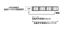
- FIG. 9 is a diagram for explaining an operation of a CP (Cyclic @ Prefix) adding unit included in the transmitter according to the second embodiment;
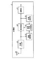
- FIG. 1 is a diagram illustrating a configuration example of the transmitter according to the first embodiment.
- the transmitter 1 according to the present embodiment includes a modulation unit 11, a spreading code generation unit 12, a spreading unit 13, a transmission filter 14, and a transmission antenna 15.
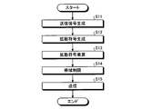
- FIG. 2 is a flowchart illustrating an example of an operation of the transmitter 1 according to the first embodiment.
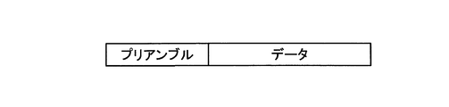
- FIG. 3 is a diagram illustrating a frame configuration of a signal transmitted by the transmitter 1 according to the first embodiment.
- the signal transmitted by the transmitter 1 is composed of a preamble and data.
- a known bit pattern hereinafter, referred to as a known sequence
- the known sequence transmitted by the preamble is used by the initial acquisition unit and the synchronization follow-up unit, which are processes for estimating the timing of the spreading code.
- a known sequence is input to the modulator 11 of the transmitter 1 at the timing of transmitting a preamble, and information bits are input at the timing of transmitting data.
- the modulation unit 11 modulates the input known sequence and the information bits to generate a modulation signal that is a transmission signal, and outputs the generated modulation signal to the spreading unit 13 (step S11).
- the modulator 11 can use, for example, PSK (Phase Shift Keying) and FSK (Frequency Shift Keying) as the modulation method.
- PSK Phase Shift Keying
- FSK Frequency Shift Keying
- the modulator 11 receives the information bits in units of 2 bits and receives a complex signal corresponding to the value indicated by the 2 information bits. Is output.
- the spreading code generation unit 12 generates a spreading code used in a process in which the spreading unit 13 spreads the modulation signal input from the modulation unit 11 over a wide band, and transfers the generated spreading code to the spreading unit 13 (Step S12). .
- a code having good correlation characteristics is used as a spreading code.
- a code having a good correlation characteristic is a code having a maximum value of the autocorrelation function when there is no timing shift, and having a low autocorrelation function when there is a timing shift.
- An example of a code having good correlation characteristics is a Zadoff-Chu sequence. When the sequence length Nc is an even number, the t-th element C (t) of the Zadoff-Chu sequence C is represented by Expression (1).
- C (t) exp (jM c ⁇ t 2 / N c ) (1)
- M c is a sequence parameter and has a disjoint relationship with N c .
- the spreader 13 multiplies the modulated signal input from the modulator 11 by the spread code input from the spread code generator 12 to perform direct spectrum spreading (step S13).
- Spreading section 13 passes a direct spread spectrum signal, which is a modulated signal after direct spread spectrum, to transmission filter 14.
- the transmission filter 14 performs band limitation on the direct spread spectrum signal input from the spreading unit 13, and passes the band-limited signal to the transmission antenna 15 (step S14).
- the transmission antenna 15 transmits the signal passed from the transmission filter 14 (Step S15).
- the signal output from the transmission filter 14 is converted from a digital signal to an analog signal, and after being up-converted, transmitted from the transmission antenna 15.
- FIG. 4 is a diagram illustrating a configuration example of the receiver according to the first embodiment.
- the receiver 2 according to the present embodiment includes a reception antenna 21, a reception filter 22, an initial acquisition unit 23, a spreading code generation unit 24, a despreading unit 25, a synchronization tracking unit 26, and a demodulation unit 27. , Is provided.
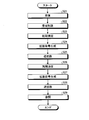
- FIG. 5 is a flowchart illustrating an example of an operation of the receiver 2 according to the first embodiment.
- the receiving antenna 21 receives the signal transmitted from the transmitter 1 and passes the received signal to the receiving filter 22 (Step S21).
- the reception filter 22 performs band limitation on the received signal passed from the reception antenna 21, and passes the band-limited received signal to the initial acquisition unit 23 and the despreading unit 25 (step S22).
- the signal received by the receiving antenna 21 is down-converted, converted from an analog signal to a digital signal, and then subjected to band limitation in the receiving filter 22.
- the initial capturing unit 23 performs initial capturing based on the signal passed from the reception filter 22 (Step S23). More specifically, the initial capturing unit 23 performs coarse synchronization for estimating the timing with an accuracy that the error from the spread code timing is within ⁇ ⁇ ⁇ chip. That is, when the initial capture unit 23 estimates a timing that is equal to or more than “(spread code timing) ⁇ (1 / chip)” and equal to or less than “(spread code timing) + (1/2 chip)”, Detection.
- the spreading code timing is the timing at which the spreading unit 13 multiplies the modulation signal by the spreading code in the transmitter 1, and the chip means a unit of one element of the spreading code.
- the initial capturing unit 23 detects the timing shifted by ⁇ 1 sample from the spread code timing, but still performs the positive detection. Details of the operation of the initial capturing unit 23 will be described later.
- the initial acquisition unit 23 notifies the spreading code generation unit 24 of the estimated timing detected in the coarse synchronization.
- the initial capturing unit 23 constitutes a timing detection device according to the present invention.
- the spread code generation unit 24 generates a spread code for the despreading unit 25 to perform despreading described later (step S24). Note that the spread code generated by the spread code generation unit 24 is the same as the spread code generated by the spread code generation unit 12 of the transmitter 1.
- the spreading code generation unit 24 outputs the generated spreading code to the despreading unit 25 according to the estimation timing notified from the initial capturing unit 23.
- the despreading unit 25 despreads the received signal by multiplying the band-limited received signal input from the reception filter 22 by the complex conjugate of the spread code input from the spread code generation unit 24 (step S25). ). The despreading unit 25 transfers the signal after the despreading in step S25 to the synchronization tracking unit 26.
- the synchronization tracking unit 26 performs a synchronization tracking process based on the signal input from the despreading unit 25 (step S26).
- the synchronization tracking unit 26 employs a synchronization tracking technology for arbitrary symbol timing, which is well known to those skilled in the art. Is applied, the error of the spread code timing is corrected. The synchronization follower 26 notifies the spread code generator 24 of the corrected timing.
- the spreading code generator 24 generates a spreading code for the despreading unit 25 to perform despreading (Step S27).
- the spreading code generation unit 24 outputs the generated spreading code to the despreading unit 25 in accordance with the corrected timing notified from the synchronization tracking unit 26. That is, when the corrected timing is notified from the synchronization tracking unit 26, the spread code generation unit 24 outputs the spread code at the corrected timing notified from the synchronization tracking unit 26.
- the spread code generation unit 24 when the estimated timing is notified from the initial acquisition unit 23 without notifying the corrected timing from the synchronization tracking unit 26, the spread code generation unit 24 generates the spread code at the estimated timing notified from the initial acquisition unit 23. Output.
- the despreading unit 25 despreads the band-limited received signal input from the reception filter 22 based on the spread code input from the spread code generation unit 24 in step S27 (step S28). That is, the despreading unit 25 multiplies the band-limited received signal input from the reception filter 22 by the complex conjugate of the spread code input from the spread code generation unit 24 in step S27 to despread the received signal. Spread.
- the despreading unit 25 transfers the received signal after the despreading in Step S28 to the demodulation unit 27.
- the demodulation unit 27 demodulates the despread received signal received from the despreading unit 25 (Step S29).
- FIG. 6 is a diagram illustrating a configuration example of the initial capturing unit 23 according to the first embodiment.
- the initial acquisition unit 23 includes a spreading code generation unit 231, a spreading code multiplication unit 232, a correlation value addition unit 233, a partial correlation value addition unit 234, power calculation units 235 and 236, an addition processing unit 237, Power memories 238 and 239, a sample combining unit 240, a weighting combining unit 241, and a threshold value determining unit 242 are provided.
- the correlation value addition unit 233 and the power calculation unit 235 constitute a first correlation power calculation unit 23A
- the partial correlation value addition unit 234, the power calculation unit 236, and the addition processing unit 237 include a second correlation power calculation unit 23B. Is configured.
- the sample combining section 240, the weighting combining section 241 and the threshold value determining section 242 constitute a timing detecting section 23C.
- FIG. 7 is a flowchart illustrating an example of an operation of the initial capturing unit 23 according to the first embodiment.
- the spreading code generation unit 231 generates the complex conjugate of the spreading code used in the transmitter 1, that is, the spreading code used when the spreading unit 13 directly spreads the spectrum of the modulated signal in the transmitter 1, and generates the spreading code.
- the output is output to the multiplier 232 (step S31).
- the spreading code generation unit 231 When the spreading codes used in the transmitter 1 are c0 to c7, the spreading code generation unit 231 generates c0 * to c7 * .
- the spreading code multiplication unit 232 multiplies the band-limited received signal passed from the receiving filter 22 in the preceding stage of the initial capturing unit 23 by the complex conjugate of the spreading code passed from the spreading code generation unit 231 (step S32). ).
- Spreading code multiplying section 232 transfers the multiplication result obtained by multiplying the band-limited received signal by the complex conjugate of the spreading code to correlation value adding section 233 and partial correlation value adding section 234.
- the multiplication result output by the spreading code multiplication unit 232 is a correlation value between the received signal after band limitation and the spreading code.
- the delay elements 251 to 266 each correspond to a 1 / N ovs chip length and hold a signal in sample units.
- c0 * to c7 * are complex conjugates of the spread code input from the spread code generation unit 231.
- the spreading code multiplication section 232 shown in FIG. 8 inputs the band-limited received signal input from the reception filter 22 to the delay element 251 in sample units, and shifts the signal to the right delay element at each sample timing. Also, the spreading code multiplication unit 232 calculates the band-limited received signal input to the delay elements 252, 254, 256, 258, 260, 262, 264, and 266 and the complex conjugates c0 * to c7 * of the spreading code. The multiplication is performed to obtain multiplication results a0 to a7 at each sample timing.
- the spreading code multiplication unit 232 transfers the multiplication results a0 to a7, which are correlation value sequences, to the correlation value addition unit 233 and the partial correlation value addition unit 234.
- the spreading code multiplication unit 232 uses Operates at sample timing.
- the correlation value addition unit 233 uses Operates at sample timing.
- the power calculation units 235 and 236, and the addition processing unit 237 use Operates at sample timing.
- Correlation power memories 238 and 239 store signals input at the sample timing.
- the partial correlation value addition unit 234 of the second correlation power calculation unit 23B divides the multiplication results a0 to a7 passed from the spreading code multiplication unit 232 into a plurality of blocks, and adds the multiplication results of the same block to each other. , A partial correlation addition value is generated (step S34). For example, the partial correlation value adding unit 234 divides the multiplication results a0 to a7 into two blocks, divides the result into two blocks, and adds each block to generate two partial correlation addition values.
- the two partial correlation addition values b1 and b2 after the addition are transferred to the power calculation unit 236.
- the power calculation unit 235 of the first correlation power calculation unit 23A calculates the power value
- the value is passed to the correlation power memory 238 as a value (step S35).
- the power calculator 236 of the second correlation power calculator 23B calculates the power values
- the addition processing unit 237 of the second correlation power calculation unit 23B combines the plurality of partial correlation power values passed from the power calculation unit 236.
- the addition processing unit 237 combines two partial correlation power values as
- a second correlation power value to the correlation power memory 239 step S37.
- the correlation power memory 238 at the subsequent stage of the first correlation power calculator 23A is configured to be able to hold the correlation power value for one cycle, which is equal to the spreading code length ⁇ the number of oversamples.
- the correlation power memory 238 stores the first correlation power value passed from the power calculator 235 for one cycle (step S38). After the first correlation power value for one cycle is accumulated, the correlation power memory 238 outputs the held first correlation power value for one cycle to the weighting synthesis unit 241.
- the correlation power memory 239 at the subsequent stage of the second correlation power calculation unit 23B is configured to be able to hold the correlation power value for one cycle, similarly to the correlation power memory 238.
- the correlation power memory 239 stores the second correlation power value, which is the partial correlation combined power value passed from the addition processing unit 237, over one cycle (step S39). After accumulating the second correlation power value for one cycle, the correlation power memory 239 outputs the held second correlation power value for one cycle to the sample synthesizing unit 240 and the threshold determining unit 242. In the processes after the correlation power memories 238 and 239, the processes that have been operating at the sample timing are changed to the operations at the symbol timing.
- the sample synthesizing unit 240 determines whether the timing is k + 1, k ⁇ 1, k + 2, and k ⁇ 2 with respect to the second correlation power value when the timing is k. Are added together.
- the second combined power value output by the sample combining unit 240 after combining is referred to as a sample combined power value.
- the initial capturing unit 23 performs coarse synchronization for detecting the timing so that the error from the spread code timing is within 1/2 chip
- the second correlation power values of log 2 (N ovs ) before and after each timing are combined to generate sample combined power values e0 to e15 (see FIG. 10).
- the sample combining unit 240 transfers the sample combined power value (e0, e1,..., E15) over one cycle to the weighting combining unit 241.
- the weighting / synthesizing unit 241 compares the first correlation power value passed from the correlation power memory 238 and the sample combined power value passed from the sample combining unit 240 at each sample timing, that is, at the same sample timing.
- the objects are weighted and synthesized (step S41). After the weighting synthesis, the weighting synthesis unit 241 transfers the weighted synthesized power value obtained by the weighting synthesis to the threshold determination unit 242.
- step S41 the weighting / synthesizing unit 241 multiplies the previously calculated weighting coefficient by the sample synthesized power value passed from the sample synthesizing unit 240, and adds the result to the first correlation power value to perform weighted synthesis.
- a method of calculating the weighting coefficient will be described with reference to FIGS.
- FIG. 11 is a diagram illustrating an example of a first correlation power value output by the first correlation power calculation unit 23A
- FIG. 12 is a diagram illustrating an example of a sample combined power value output by the sample combining unit 240.
- the designer of the receiver 2 calculates a weighting coefficient based on, for example, the maximum value of the first correlation power and the maximum value of the sample combined power value.
- the designer first checks the maximum power value within one cycle of the spreading code for each of the first correlation power value and the sample combined power value. At this time, the first correlation power value and the sample combined power value do not include a noise component. Thereafter, the designer calculates a weighting coefficient such that the two confirmed maximum power values are combined with equal power.
- the weighting coefficient varies depending on the spreading code length N c , the number of oversamples N ovs , the value of the frequency offset, and the like.
- the weighting / synthesizing unit 241 may have a function of calculating a weighting factor, and the weighting / synthesizing unit 241 may calculate the weighting factor when a predetermined operation is performed on the receiver 2. .
- the threshold determining unit 242 detects the maximum power value from the weighted combined power values for one cycle passed from the weight combining unit 241 and determines the threshold, that is, compares the maximum power value with a predetermined threshold. Is performed (step S42). When the maximum power value exceeds the threshold value, the timing corresponding to the maximum power value is transferred to the spreading code generation unit 24 of the receiver 2 as the estimation timing, that is, the estimation result of the spreading code timing. In the receiver 2, the following method is used as a threshold setting method used by the threshold determination unit 242 in the threshold determination.
- the threshold determination unit 242 calculates the average of the partial correlation power values for one cycle before the sample synthesis, which is passed from the correlation power memory 239 at the subsequent stage of the second correlation power calculation unit 23B, and calculates the constant ⁇ ( 1 ⁇ ⁇ ) times is set as the threshold.
- the value of the constant ⁇ is set to be larger, false alarms that establish an erroneous synchronization point can be reduced, but the initial acquisition takes time.
- the value of the constant ⁇ is set to be smaller, the initial acquisition time can be reduced. The relationship is that false alarms increase.
- the receiver 2 After the threshold value determination unit 242, the receiver 2 performs the processing after the spread code generation unit 24 by the above-described operation.
- the initial acquisition unit 23 of the receiver 2 uses the first correlation powers in which the addition ranges of the correlation value sequences obtained by multiplying the received signal by the complex conjugate of the spreading code are different from each other. It includes a calculator 23A and a second correlation power calculator 23B. Specifically, the first correlation power calculation unit 23A adds all the correlation values of the correlation value sequence, and outputs the obtained power value as the first correlation power value. The second correlation power calculation unit 23B divides the correlation value sequence into a plurality of blocks, adds the correlation values in the blocks for each block, calculates the power value of the obtained addition result, and further Is output as a second correlation power value.
- the initial capturing unit 23 weights and combines the first correlation power value calculated by the first correlation power calculation unit 23A and the second correlation power value calculated by the second correlation power calculation unit 23B. Then, the initial capturing unit 23 compares the power value (weighted combined power value) obtained by the weighted combination with the threshold, and determines the sample timing corresponding to the power value exceeding the threshold as the estimated timing. Further, in the present embodiment, the weighting coefficient used for the weighting synthesis is calculated based on the first correlation power value and the second correlation power value. Specifically, for each of the first correlation power value and the second correlation power value, the maximum power value within one cycle of the spreading code is checked in advance with the noise component removed, and the two maximum power values are checked. Are used as weighting coefficients.
- the initial acquisition unit 23 uses the first correlation power calculation unit 23A and the second correlation power calculation unit 23B in parallel, a large correlation power value of the spreading code timing can be observed. It is possible to improve the deterioration of synchronization accuracy due to the side lobe of the correlation characteristic, which is a problem of the conventional initial acquisition method described in Patent Document 1.
- the initial acquisition unit 23 performs a weighted synthesis of the correlation power value calculated by the first correlation power calculation unit 23A and the correlation power value calculated by the second correlation power calculation unit 23B, so that the frequency When the offset is small, the ratio of the first correlation power value can be increased, and when the frequency offset is large, the ratio of the second correlation power value can be increased.
- FIG. 13 is a diagram for explaining why the second correlation power value calculated by the second correlation power calculation unit 23B is strong in frequency offset tolerance.
- FIG. 13 is a diagram showing, on a complex plane, multiplication results a0 to a7 obtained by the spreading code multiplication unit 232 of the initial acquisition unit 23 in FIG. 8 with the frequency offset set to 1 / Nc .
- Expression (2) is obtained.
- 2 0 (2)
- the second correlation power calculator 23B splits and adds the multiplication result shorter than the first correlation power calculator 23A and performs power calculation, thereby increasing the resistance to the frequency offset.
- the second correlation power calculation unit 23B calculates the correlation power by dividing the multiplication result, the correlation characteristic is inferior to that of the first correlation power calculation unit 23A under the condition that the frequency offset is small. Therefore, in the present embodiment, the first correlation power value and the second correlation power value are weighted and combined to improve the synchronization determination accuracy regardless of the presence or absence of the frequency offset.
- the synchronization determination accuracy can be improved.
- the sample synthesizing section 240 at the subsequent stage of the second correlation power calculating section 23B can be omitted.
- the configuration including the sample combining unit 240 as shown in FIG. 6 is adopted, the synchronization determination accuracy can be further improved.
- the second correlation power value calculated by the second correlation power calculation unit 23B is combined with the second correlation power value at a timing of log 2 (N ovs ) before and after over one cycle of the spreading code.
- the power values at the preceding and following sample timings are combined, the power value at the timing of the positive detection can be relatively increased, and the power value at the timing of the false alarm can be relatively reduced. As a result, it is possible to improve the deterioration of the synchronization accuracy due to the side lobe accompanying the increase in the number of divisions.
- first correlation power calculation unit 23A and second correlation power calculation unit 23B it is possible to accurately perform initial acquisition regardless of the presence or absence of a frequency offset.
- the configuration uses the correlation power calculation unit 23B, the configuration is not limited to the configuration in which the multiplication result is divided into two.
- the second correlation power calculator 23B may be configured to use another division number that can equally divide the spreading code, such as three divisions or four divisions.
- the second correlation power calculation unit 23B having the number of divisions corresponding to the maximum frequency offset assumed in the system is used.
- the first correlation power calculation unit 23A and the second correlation power calculation unit 23B divided into two are configured in parallel, but the second correlation power calculation units 23B having different numbers of divisions are used. May be used.
- the configuration uses a first correlation power calculation unit 23A, a second correlation power calculation unit 23B divided into two, and a second correlation power calculation unit 23B divided into four.
- a first correlation power calculation unit 23A Compared with the configuration shown in FIG. 6, by using this configuration, it is possible to detect the timing at which the correct detection is performed even under the condition where the frequency offset is large.
- the second correlation power calculation unit 23B having a different number of divisions into two and four is used in parallel, the appearance pattern of the side lobe of the correlation power value differs depending on the number of divisions.
- the synchronization determination accuracy can be improved as compared with the configuration using the calculation unit 23A and the quadrant divided second correlation power calculation unit 23B.
- the processing results of the power calculating units 235 and 236 are transferred to the correlation power memories 238 and 239, respectively, but the present invention is not limited to this.
- the configuration may be such that averaging is performed between the correlation power value held in the correlation power memories 238 and 239 one symbol before and the correlation power value newly calculated by the power calculation units 235 and 236.
- the correlation power memories 238 and 239 hold the correlation power values after the averaging, and it is possible to perform a good threshold determination in which noise components are suppressed.
- the second correlation power calculation unit 23B uses the partial correlation value addition unit 234, the power calculation unit 236, and the addition processing unit 237.
- the present invention is not limited to this. It can also be applied to a configuration including a phase difference calculator, such as the initial acquisition unit disclosed in Non-Patent Document 1.
- the configuration of the initial capturing unit 23 in this case is illustrated in FIG.
- FIG. 14 is a diagram illustrating a modification of the initial capturing unit included in the receiver 2 according to the first embodiment.
- the difference between the initial capturing unit 23a shown in FIG. 14 and the initial capturing unit 23 shown in FIG. 6 is that the second correlation power calculating unit 23B-2 in FIG.
- the same processing as in FIG. 6 is denoted by the same reference numeral, and the detailed description is omitted.
- the partial correlation value adding unit 234 divides the multiplication result passed from the spreading code multiplying unit 232 into two parts and adds them to obtain partial correlation addition values b0 and b1.
- the addition processing unit 282 adds the calculation result d0 of the phase difference passed from the phase difference calculation unit 281 and passes the addition result to the power calculation unit 236. Processing after the power calculation unit 236 is the same as that described above.
- the second correlation power value output from the second correlation power calculation unit 23B-2 is made smaller than the first correlation power calculation unit 23A by the process of obtaining the phase difference. Since many multiplications are performed, the power value is larger than the first correlation power value output from the first correlation power calculator 23A. Therefore, the weighting synthesis unit 241 can achieve good initial acquisition performance by performing weighting synthesis at an appropriate power ratio. With this configuration, it is possible to accurately perform the initial acquisition in a short time even under the condition where the frequency offset exists.
- sample combining section 240 is not used downstream of first correlation power calculating section 23A, but is used only downstream of second correlation power calculating section 23B.
- the configuration is not limited to this, and a sample combining unit may be used at a stage subsequent to the first correlation power calculating unit 23A.
- the new sample synthesizing unit is arranged after the correlation power memory 238.
- the operation of the sample combining unit subsequent to the first correlation power calculating unit 23A is the same as that of the sample combining unit 240 described in the first embodiment.
- each cycle of the first correlation power value and the sample synthesis power value in a state where the noise component is removed is one cycle of the spread code.
- the maximum power value in the above is checked in advance, and a weighting coefficient is used to combine the two maximum power values with equal power, but the present invention is not limited to this.
- the average value (refer to FIGS. 11 and 12) for one cycle of the spreading code is obtained for each of the first correlation power value and the sampled combined power value in a state where the noise component is removed. Then, a weighting coefficient may be used so that these average values become equal.
- the ratio of the first correlation power value can be increased as compared with the case of using the above-described weighting coefficient with the maximum power value being equal power, and the synchronization accuracy can be improved when the frequency offset is small.
- the accuracy deteriorates.
- the accuracy can be improved when the frequency offset is small, while the accuracy is not greatly degraded when the frequency offset is large, as compared with the case where the weighting coefficient with the maximum power value being equal power is used.
- the weighting coefficient may not be a fixed value set in advance, but may be changed adaptively for each symbol. For example, a weighting coefficient for which the average value of the first correlation power value held by the correlation power memory 238 is equal to the average value of the sample combined power value held by the sample combining unit 240 is calculated for each symbol.
- the weighting coefficient is appropriately updated, for example, by the weighting synthesis unit.
- the average value of the correlation power values held by the correlation power memory 239 is used, but the present invention is not limited to this.
- a configuration may be used in which the average value of the weighted combined power values output by the weighting and combining unit 241 is used. With such a configuration, it is possible to generate an accurate threshold value including both information of the first correlation power value and the sample combined power value output from the sample combining unit 240, and to perform a good synchronization determination. Accuracy can be achieved.
- the threshold value used by the threshold value determination unit 242 may be adaptively changed instead of a fixed value set in advance. For example, an average value and a maximum value of the first correlation power value for one cycle stored in the correlation power memory 238 are obtained, and the maximum value is ⁇ times the average value ( ⁇ is a predetermined constant and ⁇ > 1). ), A constant ⁇ times the average value of the weighted combined power values is used as a threshold by the threshold determination unit 242. On the other hand, when the maximum value of the weighted combined power value does not exceed ⁇ times the average value, there is a method in which the threshold is a value obtained by multiplying the constant ⁇ by a constant ⁇ ( ⁇ ⁇ 1).
- the maximum correlation power value of the first correlation power calculation unit stored in the correlation power memory 238 decreases when the frequency offset is large.
- the threshold can be adaptively changed according to the magnitude of the frequency offset, and the initial acquisition time can be reduced regardless of the frequency offset condition.
- the receiving antenna 21 is realized by an antenna device.
- the reception filter 22 is realized by a filter circuit.
- the spreading code multiplying unit 232 of the initial capturing unit 23 is realized by the circuit having the configuration shown in FIG. 8 as described above.
- Each component other than the spreading code multiplication unit 232 of the initial acquisition unit 23 is realized by a processing circuit.
- These processing circuits may be realized by dedicated hardware, or may be control circuits using a CPU (Central Processing Unit).
- FIG. 15 is a diagram illustrating a processing circuit that implements the receiver 2 according to the first embodiment.
- the processing circuit 100 is a single circuit, a composite circuit, a programmed processor, a parallel programmed processor, an ASIC (Application Specific Integrated Circuit), an FPGA (Field Programmable Gate Array), or a combination thereof.
- ASIC Application Specific Integrated Circuit
- FPGA Field Programmable Gate Array
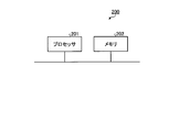
- FIG. 16 is a diagram illustrating a configuration example of a control circuit that realizes the receiver 2 according to the first embodiment.
- the control circuit 200 includes a processor 201 such as a CPU and a memory 202.
- the memory 202 stores a program for realizing the function of each component other than the spreading code multiplication unit 232 of the initial acquisition unit 23.
- the processor 201 reads and executes the above-described program stored in the memory 202, thereby realizing each component other than the spreading code multiplying unit 232 of the initial capturing unit 23.
- the memory 202 is also used as a temporary memory in each process performed by the processor 201.
- the initial capturing unit 23a shown in FIG. 14 is realized by a circuit similar to the circuit that realizes the initial capturing unit 23.
- the spread code generator 24 is realized by the processing circuit 100 shown in FIG. 15 or the control circuit 200 shown in FIG.
- the despreading unit 25 is realized by a circuit in which a plurality of delay elements and a plurality of multipliers are combined.
- the synchronization follow-up unit 26 is realized by the processing circuit 100 shown in FIG. 15 or the control circuit 200 shown in FIG.
- the demodulation unit 27 is realized by a demodulator.
- the modulator 11 of the transmitter 1 according to the first embodiment is realized by a modulator.
- the spreading code generator 12 is realized by a circuit similar to the processing circuit 100 shown in FIG. 15 or the control circuit 200 shown in FIG.
- the spreading unit 13 is realized by a circuit in which a plurality of delay elements and a plurality of multipliers are combined.
- the transmission filter 14 is realized by a filter circuit.
- the transmitting antenna 15 is realized by an antenna device.
- Embodiment 2 FIG. Next, a second embodiment will be described.
- a transmitter generates a transmission signal by repeating a signal after direct spread spectrum a plurality of times. This is a method known as one of spread spectrum techniques. With this technique, the transmitter distributes the transmission signal spectrum at equal intervals on the frequency axis.
- the initial acquisition unit of the receiver according to the second embodiment determines the correlation value addition cycle of the first correlation power calculation unit and the second correlation power calculation unit according to the number of repetitions of the direct spread spectrum signal on the transmission side.
- the configuration and operation of the transmitter and the operation of the receiver are different from those of the first embodiment.
- portions different from the first embodiment will be described, and description of the same portions as the first embodiment will be omitted.
- FIG. 17 is a diagram illustrating a configuration example of a transmitter according to the second embodiment.
- a transmitter 1a according to the second embodiment includes an up-sampling unit 31 between the spreading unit 13 and the transmission filter 14 of the transmitter 1 (see FIG. 1) described in the first embodiment. , A frequency shift unit 32, and a CP adding unit 33.
- FIG. 18 is a flowchart illustrating an example of an operation of the transmitter 1a according to the second embodiment.
- the flowchart shown in FIG. 18 is obtained by adding steps S51 to S53 between steps S13 and S14 of the flowchart shown in FIG.
- the up-sampling unit 31 compresses the signal length of the direct spread spectrum signal input from the spreading unit 13 to 1 / P, and then repeats the compressed direct spread spectrum signal P times (step S51).
- P is an integer of 2 or more.
- Upsampling unit 31 performs an iterative process, length of spreading code N c is repeated P times, length produces a direct spread spectrum signal N c ⁇ P.
- FIG. 19 is a diagram for explaining processing of the up-sampling unit 31 included in the transmitter 1a according to the second embodiment.
- the hatched portion of the signal indicates the first element of the spreading code.
- the up-sampling unit 31 compresses the signal length to 1 / by increasing the sample rate by four times.
- the up-sampling section 31 repeats the signal compressed to a length of 1/4 four times to generate an up-sampled direct spread spectrum signal.
- the direct spread spectrum signal after up-sampling has two spreading code periods.
- the up-sampling section 31 transfers the up-sampled direct spread spectrum signal to the frequency shift section 32.
- the frequency shift unit 32 performs phase rotation on the signal input from the up-sampling unit 31 by a predetermined amount of phase rotation to shift the frequency of the input signal (step S52).
- the frequency shift unit 32 transfers the frequency-shifted direct spread spectrum signal to the CP adding unit 33.
- the CP adding unit 33 duplicates a predetermined number of sample values from the end of the signal input from the frequency shift unit 32 as a cyclic prefix (CP: Cyclic @ Prefix). It is added to the beginning (step S53).
- FIG. 20 is a diagram for explaining the operation of the CP adding unit 33 included in the transmitter 1a according to the second embodiment.
- the CP adding unit 33 passes the direct spread spectrum signal after the CP addition to the transmission filter 14. Subsequent processing of the transmitter 1a is the same as that of the transmitter 1 according to the first embodiment.
- the up-sampling unit 31, the frequency shift unit 32, and the CP adding unit 33 of the transmitter 1a are realized by the processing circuit 100 or the control circuit 200 described in the first embodiment.
- the configuration of the receiver according to the second embodiment is the same as that of the receiver 2 according to the first embodiment (see FIG. 4). However, the operation of the initial capturing unit 23 is different.
- the initial capturing unit 23 according to the second embodiment will be described with reference to FIG. 6 illustrating the configuration of the initial capturing unit 23 according to the first embodiment.
- the flowchart showing the operation of the receiver 2 according to the second embodiment is the same as the flowchart (see FIG. 5) showing the operation of the receiver 2 according to the first embodiment.
- the initial capturing unit 23 estimates the timing of the illustrated spreading code period # 2 for the direct spread spectrum signal after the CP addition shown in FIG.
- ⁇ Correlation value addition section 233 of first correlation power calculation section 23A adds the multiplication result passed from spreading code multiplication section 232 with a length equivalent to spreading code period # 2 shown in FIG.
- the partial correlation value adder 234 of the second correlation power calculator 23B adds the multiplication result passed from the spread code multiplier 232 with a length equal to the spread code period # 1 shown in FIG. That is, the partial correlation value adding unit 234 divides the spreading code period # 2 into P divisions and adds them. For example, when the receiver 2 receives the direct spectrum spread signal after the up-sampling having the configuration shown in FIG. 19, the partial correlation value adder 234 divides the spread code period # 2 into four and adds them.
- the processing performed by the components at the subsequent stage of the correlation value adding unit 233 and the components at the subsequent stage of the partial correlation value adding unit 234 are the same as those of the initial acquisition unit 23 according to the first embodiment. Is the same.
- the despreading unit 25 (see FIG. 4) of the receiver 2 according to the second embodiment uses the spreading code input from the spreading code generation unit 24 to input the signal from the reception filter 22 as in the first embodiment. Despread the signal. However, based on the estimated timing detected by the initial acquisition unit 23 or the synchronization tracking unit 26 or the corrected timing, only the portion excluding the CP is despread.
- the demodulation unit 27 performs a demodulation process corresponding to the signal transmitted by the transmitter 1a illustrated in FIG. This processing can be realized by the following configuration, for example.
- the demodulation unit 27 first performs equalization processing on the despread signal received from the despreading unit 25 to correct waveform distortion received on the transmission path. After performing the equalization process, the demodulation unit 27 performs a process of removing the frequency shift given by the frequency shift unit 32 of the transmitter 1a. Thereafter, the demodulation unit 27 performs the synthesis according to the number of repetitions P performed by the up-sampling unit 31 of the transmitter 1a. The synthesis is performed as described below.
- the demodulation unit 27 samples the signal having the same element number of the spreading code before the repetition by the up-sampling unit 31 of the transmitter 1a for the signal whose spreading code period is N c ⁇ P after removing the frequency shift. These are combined to form a signal of length Nc . After the combining, the demodulation unit 27 performs a demodulation process corresponding to the modulation process performed by the modulation unit 11 of the transmitter 1a.
- the up-sampling unit 31 of the transmitter 1a is configured to generate a transmission signal by repeating the spectrum-spread signal a plurality of times. Further, in the initial acquisition unit 23 of the receiver 2, a correlation value is added by a length corresponding to the spreading code cycle after the repetition by the up-sampling unit 31 and the spreading code cycle before the repetition.
- the calculation unit and the second correlation power calculation unit are used in combination.
- the correlation characteristic of the entire spread code cycle can be obtained instead of the partial correlation, so that a correlation value in which side lobes are suppressed can be obtained.
- the correlation characteristic of the first correlation power calculator together with this characteristic, the synchronization determination accuracy can be improved.
Landscapes
- Engineering & Computer Science (AREA)
- Computer Networks & Wireless Communication (AREA)
- Signal Processing (AREA)
- Synchronisation In Digital Transmission Systems (AREA)
- Radar Systems Or Details Thereof (AREA)
Abstract
受信装置は、直接スペクトル拡散が実施された受信信号に対し、直接スペクトル拡散に用いられた拡散符号の複素共役を乗算して相関値系列を生成する拡散符号乗算部(232)と、拡散符号乗算部(232)が乗算を行うごとに生成される相関値系列の各相関値を加算して相関加算値を生成し、相関加算値の電力値である第1の相関電力値を算出する第1の相関電力算出部(23A)と、相関値系列を複数のブロックに分割し、ブロックごとに、ブロック内の各相関値を加算して部分相関値を生成するとともに部分相関値の電力値を求め、ブロックごとに求めた電力値同士を加算して第2の相関電力値を算出する第2の相関電力算出部(23B)と、第1の相関電力値と第2の相関電力値とに基づいて、受信信号の送信元の送信装置が直接スペクトル拡散において送信信号に拡散符号を乗算したタイミング、を検出するタイミング検出部(23C)と、を備える。
Description
本発明は、直接スペクトル拡散が実施された信号を受信する受信装置、タイミング検出装置およびタイミング検出方法に関する。
直接スペクトル拡散通信において、送信機は、変調信号に拡散符号を乗じることで信号を広帯域に拡散し、拡散された信号を受信機に送信する。受信機は、送信機で用いた拡散符号と同一の拡散符号を受信信号に乗じることで逆拡散し、逆拡散後の受信信号を復調する。受信機が正しく逆拡散を行うためには、拡散符号タイミング、すなわち、送信機が変調信号に拡散符号を乗じたタイミングを推定する初期捕捉を行い、推定したタイミングで拡散符号を受信信号に乗じる必要がある。
従来の初期捕捉方式の一例である非特許文献1に記載の方式では、受信信号に拡散符号を乗じる整合フィルタ(Matched Filter)を複数のセグメントに分割し、各セグメントから出力される信号同士の位相差を検出する。さらに、検出した位相差を過去に受信したシンボルにおいて検出した位相差と平均化し、平均化後の位相差に基づいて、拡散符号タイミングである拡散系列タイミングを推定する。これにより、周波数オフセットが存在する環境においても精度良く短時間で初期捕捉を完了することができる。
東中 雅嗣、他,"拡散系列タイミングと周波数オフセットを同時に推定する直接スペクトル拡散通信用初期捕捉方式",電子情報通信学会論文誌 B Vol.J98-B No.12 pp.1277-1288,2015.
非特許文献1に記載の初期捕捉方式では、整合フィルタの分割数を増やすことにより周波数オフセットに対する耐性は高まるが、拡散系列タイミング以外のサンプルタイミングに、相関値のサイドローブが出現してしまう。更に、分割数の増加だけでなく、オーバーサンプルによってもサイドローブが出現してしまう。そのため、サイドローブが存在するタイミングを拡散系列タイミングと誤判定する可能性が高まり、判定精度が劣化するという問題があった。
本発明は、上記に鑑みてなされたものであって、拡散符号タイミングの推定精度を向上させることが可能な受信装置を得ることを目的とする。
上述した課題を解決し、目的を達成するために、本発明にかかる受信装置は、直接スペクトル拡散が実施された受信信号に対し、直接スペクトル拡散に用いられた拡散符号の複素共役を乗算して相関値系列を生成する拡散符号乗算部と、拡散符号乗算部が乗算を行うごとに生成される相関値系列の各相関値を加算して相関加算値を生成し、相関加算値の電力値である第1の相関電力値を算出する第1の相関電力算出部を備える。また、受信装置は、相関値系列を複数のブロックに分割し、ブロックごとに、ブロック内の各相関値を加算して部分相関値を生成するとともに部分相関値の電力値を求め、ブロックごとに求めた電力値同士を加算して第2の相関電力値を算出する第2の相関電力算出部と、第1の相関電力値と第2の相関電力値とに基づいて、受信信号の送信元の送信装置が直接スペクトル拡散において送信信号に拡散符号を乗算したタイミング、を検出するタイミング検出部と、を備える。
本発明にかかる受信装置は、拡散符号タイミングの推定精度を向上させることができる、という効果を奏する。
以下に、本発明の実施の形態にかかる受信装置、タイミング検出装置およびタイミング検出方法を図面に基づいて詳細に説明する。なお、この実施の形態によりこの発明が限定されるものではない。
実施の形態1.
まず、本発明の実施の形態にかかる受信装置に対して信号を送信する送信装置である送信機の構成および動作について説明する。図1は、実施の形態1にかかる送信機の構成例を示す図である。本実施の形態にかかる送信機1は、変調部11と、拡散符号生成部12と、拡散部13と、送信フィルタ14と、送信アンテナ15と、を備える。
まず、本発明の実施の形態にかかる受信装置に対して信号を送信する送信装置である送信機の構成および動作について説明する。図1は、実施の形態1にかかる送信機の構成例を示す図である。本実施の形態にかかる送信機1は、変調部11と、拡散符号生成部12と、拡散部13と、送信フィルタ14と、送信アンテナ15と、を備える。
図1に示す送信機1の動作概要を説明する。図2は、実施の形態1にかかる送信機1の動作の一例を示すフローチャートである。また、図3は、実施の形態1にかかる送信機1が送信する信号のフレーム構成を示す図である。図3に示したように、送信機1が送信する信号はプリアンブルおよびデータで構成される。プリアンブルでは、受信側で既知のビットパターン(以下、既知系列と称する)が送信される。プリアンブルで送信される既知系列は、拡散符号タイミングを推定する処理である初期捕捉部と同期追従部で用いられる。送信機1の変調部11には、プリアンブルを送信するタイミングでは既知系列が入力され、データを送信するタイミングでは情報ビットが入力される。
変調部11は、入力された既知系列と情報ビットとを変調して送信信号である変調信号を生成し、生成した変調信号を拡散部13へ出力する(ステップS11)。変調部11は、変調方式として、例えばPSK(Phase Shift Keying)およびFSK(Frequency Shift Keying)を用いることができる。変調部11は、PSKの1つであるQPSK(Quadrature Phase Shift Keying)を用いて情報ビットを変調する場合、情報ビットを2ビット単位で受け取り、2ビットの情報ビットが示す値に対応した複素信号を出力する。
拡散符号生成部12は、変調部11から入力された変調信号を拡散部13が広帯域に拡散する処理で用いられる拡散符号を生成し、生成した拡散符号を拡散部13へ受け渡す(ステップS12)。本実施の形態では、拡散符号として相関特性の良い符号を用いる。相関特性が良い符号とは、タイミングのずれがない場合に自己相関関数が最大値となり、ずれがある場合は自己相関関数が低くなる符号である。相関特性の良い符号の一例は、Zadoff-Chu系列である。系列長Ncが偶数である場合、Zadoff-Chu系列Cのt番目の要素C(t)は、式(1)で表される。
C(t)=exp(jMcπt2/Nc) …(1)
C(t)=exp(jMcπt2/Nc) …(1)
ここで、Mcは系列パラメータであり、Ncと互いに素な関係にある。本実施の形態では、送信機1から送信された信号を受信する受信装置がZadoff-Chu系列を用いて初期捕捉を行う場合に、拡散符号タイミングを中心に一定の期間のサンプルタイミングにおいて相関値が大きくなる、Mc=1を用いることとする。Mc≠1の場合、拡散符号タイミングから離れたタイミングで相関値が大きくなる。
拡散部13は、変調部11から入力された変調信号と、拡散符号生成部12から入力された拡散符号とを乗算して直接スペクトル拡散を行う(ステップS13)。拡散部13は、直接スペクトル拡散後の変調信号である直接スペクトル拡散信号を送信フィルタ14へ受け渡す。
送信フィルタ14は、拡散部13から入力された直接スペクトル拡散信号に対して帯域制限を行い、帯域制限後の信号を送信アンテナ15に受け渡す(ステップS14)。
送信アンテナ15は、送信フィルタ14から受け渡された信号を送信する(ステップS15)。
なお、図1および図2では記載を省略しているが、送信フィルタ14から出力される信号は、ディジタル信号からアナログ信号に変換され、アップコンバートされた後に送信アンテナ15から送信される。
次に、本発明の実施の形態にかかる受信装置である受信機の構成および動作について説明する。図4は、実施の形態1にかかる受信機の構成例を示す図である。本実施の形態にかかる受信機2は、受信アンテナ21と、受信フィルタ22と、初期捕捉部23と、拡散符号生成部24と、逆拡散部25と、同期追従部26と、復調部27と、を備える。
図4に示す受信機2の動作概要を説明する。図5は、実施の形態1にかかる受信機2の動作の一例を示すフローチャートである。
受信アンテナ21は、送信機1から送信された信号を受信し、受信信号を受信フィルタ22に受け渡す(ステップS21)。
受信フィルタ22は、受信アンテナ21から受け渡された受信信号に対して帯域制限を行い、帯域制限実施後の受信信号を初期捕捉部23および逆拡散部25へ受け渡す(ステップS22)。
なお、図4および図5では記載を省略しているが、受信アンテナ21が受信した信号は、ダウンコンバートされ、アナログ信号からディジタル信号に変換された後、受信フィルタ22において帯域制限が行われる。
初期捕捉部23は、受信フィルタ22から受け渡された信号に基づき、初期捕捉を行う(ステップS23)。具体的には、初期捕捉部23は、拡散符号タイミングとの誤差が1/2チップ以内となる精度でタイミングを推定する、粗同期を行う。すなわち、初期捕捉部23は、「(拡散符号タイミング)-(1/2チップ)」以上、かつ「(拡散符号タイミング)+(1/2チップ)」以下、となるタイミングを推定した場合、正検出となる。ここで、拡散符号タイミングとは、送信機1において拡散部13が変調信号に拡散符号を乗算したタイミングであり、チップとは、拡散符号の1要素の単位を意味する。拡散符号の1チップに対してオーバーサンプル2倍で処理を行う場合、初期捕捉部23は、拡散符号タイミングから±1サンプルずれたタイミングを推定しても正検出となる。初期捕捉部23の動作の詳細は後述する。初期捕捉部23は、粗同期で検出した推定タイミングを拡散符号生成部24に通知する。初期捕捉部23は本発明にかかるタイミング検出装置を構成する。
拡散符号生成部24は、逆拡散部25が後述する逆拡散を行うための拡散符号を生成する(ステップS24)。なお、拡散符号生成部24が生成する拡散符号は、送信機1の拡散符号生成部12が生成する拡散符号と同一である。拡散符号生成部24は、生成した拡散符号を、初期捕捉部23から通知された推定タイミングに従って逆拡散部25へ出力する。
逆拡散部25は、受信フィルタ22から入力された帯域制限後の受信信号に、拡散符号生成部24から入力された拡散符号の複素共役を乗算することで、受信信号を逆拡散する(ステップS25)。逆拡散部25は、ステップS25で逆拡散を実施した後の信号を同期追従部26へ受け渡す。
同期追従部26は、逆拡散部25から入力される信号に基づき、同期追従処理を行う(ステップS26)。同期追従部26は、初期捕捉部23で検出された推定タイミングと拡散符号タイミングとの誤差が1/2チップ以内である場合、当業者に良く知られている、任意のシンボルタイミングの同期追従技術を適用することで、拡散符号タイミングの誤差を補正する。同期追従部26は、補正後のタイミングを拡散符号生成部24に通知する。
拡散符号生成部24は、逆拡散部25が逆拡散を行うための拡散符号を生成する(ステップS27)。拡散符号生成部24は、生成した拡散符号を同期追従部26から通知された補正後のタイミングに従って逆拡散部25へ出力する。すなわち、拡散符号生成部24は、同期追従部26から補正後のタイミングが通知された場合、同期追従部26から通知された補正後のタイミングで拡散符号を出力する。また、拡散符号生成部24は、同期追従部26から補正後のタイミングが通知されずに初期捕捉部23から推定タイミングが通知された場合、初期捕捉部23から通知された推定タイミングで拡散符号を出力する。
逆拡散部25は、ステップS27において拡散符号生成部24から入力された拡散符号に基づき、受信フィルタ22から入力された帯域制限後の受信信号を逆拡散する(ステップS28)。すなわち、逆拡散部25は、受信フィルタ22から入力された帯域制限後の受信信号に、ステップS27で拡散符号生成部24から入力された拡散符号の複素共役を乗算することで、受信信号を逆拡散する。逆拡散部25は、ステップS28で逆拡散を実施した後の受信信号を復調部27へ受け渡す。
復調部27は、逆拡散部25から受け取った逆拡散後の受信信号を復調する(ステップS29)。
続いて、受信機2の初期捕捉部23の構成および動作について詳しく説明する。タイミング検出装置に相当する初期捕捉部23は、本実施の形態において特徴的な動作を行う。図6は、実施の形態1にかかる初期捕捉部23の構成例を示す図である。初期捕捉部23は、拡散符号生成部231と、拡散符号乗算部232と、相関値加算部233と、部分相関値加算部234と、電力計算部235および236と、加算処理部237と、相関電力メモリ238および239と、サンプル合成部240と、重み付け合成部241と、閾値判定部242と、を備える。相関値加算部233と電力計算部235は第1の相関電力算出部23Aを構成し、部分相関値加算部234と、電力計算部236と、加算処理部237は第2の相関電力算出部23Bを構成する。また、サンプル合成部240、重み付け合成部241および閾値判定部242はタイミング検出部23Cを構成する。
図6に示す初期捕捉部23の動作を説明する。図7は、実施の形態1にかかる初期捕捉部23の動作の一例を示すフローチャートである。
拡散符号生成部231は、送信機1で用いられた拡散符号、すなわち、送信機1において拡散部13が変調信号を直接スペクトル拡散する際に用いられた拡散符号の複素共役を生成し、拡散符号乗算部232へ出力する(ステップS31)。送信機1で用いられた拡散符号をc0~c7とした場合、拡散符号生成部231はc0*~c7*を生成する。
拡散符号乗算部232は、初期捕捉部23前段の受信フィルタ22から受け渡された帯域制限後の受信信号に、拡散符号生成部231から受け渡された拡散符号の複素共役を乗算する(ステップS32)。拡散符号乗算部232は、帯域制限後の受信信号に拡散符号の複素共役を乗算して得られた乗算結果を相関値加算部233および部分相関値加算部234へ受け渡す。拡散符号乗算部232が出力する乗算結果は帯域制限後の受信信号と拡散符号の相関値である。
拡散符号乗算部232は、図8に示す複数の遅延素子と複数の乗算器とを用いて構成できる。図8は、拡散符号長Nc=8、オーバーサンプル数Novs=2の場合の、拡散符号乗算部232の構成例を示している。この場合、拡散符号乗算部232を構成する遅延素子はNc×Novs=16個である。遅延素子251~266はそれぞれ1/Novsチップ長に相当し、サンプル単位で信号を保持する。c0*~c7*は拡散符号生成部231から入力される拡散符号の複素共役である。拡散符号乗算部232を構成する乗算器は、拡散符号長と等しいNc=8個である。図8に示した拡散符号乗算部232は、受信フィルタ22から入力された帯域制限後の受信信号をサンプル単位で遅延素子251に入力し、サンプルタイミング毎に右側の遅延素子にシフトする。また、拡散符号乗算部232は、遅延素子252、254、256、258、260、262、264および266に入力された帯域制限後の受信信号と、拡散符号の複素共役c0*~c7*とを乗算し、サンプルタイミング毎に乗算結果a0~a7を得る。拡散符号乗算部232は、相関値系列である乗算結果a0~a7を相関値加算部233および部分相関値加算部234へ受け渡す。
ここで、初期捕捉部23において、拡散符号乗算部232と、相関値加算部233と、部分相関値加算部234と、電力計算部235および236と、加算処理部237とは、シンボルタイミングでなくサンプルタイミングで動作する。相関電力メモリ238および239は、サンプルタイミングで入力される信号を記憶する。
第1の相関電力算出部23Aの相関値加算部233は、拡散符号乗算部232から受け渡された乗算結果a0~a7をb0=a0+a1+a2+a3+a4+a5+a6+a7のように全て加算し、サンプルタイミング毎に相関加算値を生成する(ステップS33)。相関値加算部233は、相関加算値b0を電力計算部235へ受け渡す。
第2の相関電力算出部23Bの部分相関値加算部234は、拡散符号乗算部232から受け渡された乗算結果a0~a7を複数のブロックに分割し、同じブロックの乗算結果同士を加算して、部分相関加算値を生成する(ステップS34)。部分相関値加算部234は、例えば、乗算結果a0~a7を2分割して2つのブロックに分け、ブロックごとに加算して2つの部分相関加算値を生成する。乗算結果a0~a7を2分割して加算する場合、部分相関値加算部234は、拡散符号乗算部232から受け渡された乗算結果a0~a7をb1=a0+a1+a2+a3、b2=a4+a5+a6+a7のように加算し、加算後の2つの部分相関加算値b1およびb2を電力計算部236へ受け渡す。
第1の相関電力算出部23Aの電力計算部235は、相関値加算部233から受け渡された相関加算値b0の電力値|b0|2を計算し、算出した電力値を第1の相関電力値として相関電力メモリ238へ受け渡す(ステップS35)。
第2の相関電力算出部23Bの電力計算部236は、部分相関値加算部234から受け渡された部分相関加算値b1およびb2のそれぞれの電力値|b1|2および|b2|2を計算し、算出した2つの電力値である2つの部分相関電力値を加算処理部237へ受け渡す(ステップS36)。
第2の相関電力算出部23Bの加算処理部237は、電力計算部236から受け渡された複数の部分相関電力値を合成する。本実施の形態では、加算処理部237は、2つの部分相関電力値を|b1|2+|b2|2のように合成して部分相関合成電力値を生成し、生成した部分相関合成電力値を第2の相関電力値として相関電力メモリ239へ受け渡す(ステップS37)。
第1の相関電力算出部23Aの後段の相関電力メモリ238は、拡散符号長×オーバーサンプル数に相当する、1周期分の相関電力値を保持できるように構成されている。相関電力メモリ238は、電力計算部235から受け渡された第1の相関電力値を1周期にわたって記憶する(ステップS38)。1周期分の第1の相関電力値が蓄積された後、相関電力メモリ238は、保持している1周期分の第1の相関電力値を重み付け合成部241へ出力する。
第2の相関電力算出部23Bの後段の相関電力メモリ239は、相関電力メモリ238と同様に、1周期分の相関電力値を保持できるように構成されている。相関電力メモリ239は、加算処理部237から受け渡された部分相関合成電力値である第2の相関電力値を1周期にわたって記憶する(ステップS39)。1周期分の第2の相関電力値が蓄積された後、相関電力メモリ239は、保持している1周期分の第2の相関電力値をサンプル合成部240および閾値判定部242へ出力する。なお、相関電力メモリ238および239以降の処理は、サンプルタイミングで動作していた処理が、シンボルタイミングでの動作に変わる。
サンプル合成部240は、第2の相関電力算出部23Bの後段の相関電力メモリ239から受け渡された1周期分の第2の相関電力値を隣り合ったサンプルタイミングで合成する(ステップS40)。具体的には、サンプル合成部240は、タイミング毎に、前後log2(Novs)(Novs:オーバーサンプル数)個のタイミングの第2の相関電力値を合成する。例えば、オーバーサンプル数Novs=2の場合、サンプル合成部240は、タイミングがkのときの第2の相関電力値に対して、タイミングがk+1およびk-1のときの2つの第2の相関電力値を加算する。また、オーバーサンプル数Novs=4の場合、サンプル合成部240は、タイミングがkのときの第2の相関電力値に対して、タイミングがk+1、k-1、k+2、およびk-2のときの4つの第2の相関電力値を加算する。以下、サンプル合成部240が出力する、合成後の第2の合成電力値をサンプル合成電力値と称する。
次に、拡散符号長Nc=8、オーバーサンプル数Novs=2の場合を例とし、サンプル合成部240の処理について、図9および図10を用いて詳細に説明する。図9は、相関電力メモリ239からサンプル合成部240に受け渡される1周期分の第2の相関電力値の一例を示す図、図10は、サンプル合成部240が出力する1周期分のサンプル合成電力値の一例を示す図である。図9および図10において、タイミングk=0~15は、初期捕捉部23が検出するタイミングの候補である。ここで、タイミングk=15が拡散符号タイミングであり、このタイミングで、受信フィルタ22からの出力信号が持つ拡散符号と、拡散符号乗算部232が持つ拡散符号とが一致する。また、初期捕捉部23は拡散符号タイミングとの誤差が1/2チップ以内となるようにタイミングを検出する粗同期を行うため、誤差が1/2チップ以内のタイミングk=14およびk=0と推定された場合も正しいタイミングと判断し、正検出となる。タイミングk=0~15におけるそれぞれの第2の相関電力値をd0~d15とすると、サンプル合成部240は、e0=d15+d0+d1,e1=d0+d1+d2,e2=d1+d2+d3,…,e15=d14+d15+d0のように、1周期にわたって、各タイミングの前後log2(Novs)の第2の相関電力値を合成し、サンプル合成電力値e0~e15(図10参照)を生成する。図10に示すように、サンプル合成により、正検出となるタイミングk=14,15,0のそれぞれの電力値を相対的に高められる。合成後、サンプル合成部240は1周期にわたるサンプル合成電力値(e0,e1,…,e15)を、重み付け合成部241へ受け渡す。
重み付け合成部241は、相関電力メモリ238から受け渡された第1の相関電力値と、サンプル合成部240から受け渡されたサンプル合成電力値とを、サンプルタイミングごとに、すなわち、同じサンプルタイミングのもの同士で、重み付け合成する(ステップS41)。重み付け合成後、重み付け合成部241は、重み付け合成により得られた重み付け合成電力値を閾値判定部242へ受け渡す。
ステップS41において、重み付け合成部241は、あらかじめ算出しておいた重み付け係数をサンプル合成部240から受け渡されたサンプル合成電力値に乗算し、第1の相関電力値に加算することにより重み付け合成を行う。ここで、重み付け係数の算出方法について、図11および図12を用いて説明する。図11は、第1の相関電力算出部23Aが出力する第1の相関電力値の一例を示す図、図12は、サンプル合成部240が出力するサンプル合成電力値の一例を示す図である。受信機2の設計者は、例えば、第1の相関電力の最大値とサンプル合成電力値の最大値とに基づいて、重み付け係数を算出する。この場合、設計者は、まず、第1の相関電力値とサンプル合成電力値のそれぞれについて、拡散符号1周期の内の最大電力値を確認する。このとき、第1の相関電力値およびサンプル合成電力値は雑音成分を含んでいないものとする。その後、設計者は、確認した2つの最大電力値が等電力で合成されるような重み付け係数を算出する。重み付け係数は、拡散符号長Nc、オーバーサンプル数Novs、周波数オフセットの値等によって変わる。なお、重み付け係数を算出する機能を重み付け合成部241が有し、予め定められた操作が受信機2に対して行われた場合に、重み付け合成部241が重み付け係数を算出するようにしてもよい。
閾値判定部242は、重み付け合成部241から受け渡された1周期分の重み付け合成電力値の中から最大電力値を検出し、閾値判定、すなわち、最大電力値と予め定められた閾値との比較を行う(ステップS42)。最大電力値が閾値を超えている場合、最大電力値に対応したタイミングを、推定タイミング、すなわち拡散符号タイミングの推定結果として受信機2の拡散符号生成部24へ受け渡す。受信機2においては、閾値判定部242が閾値判定で使用する閾値の設定方法として、次のような方法を用いる。閾値判定部242は、第2の相関電力算出部23B後段の相関電力メモリ239から受け渡された、サンプル合成前の1周期分の部分相関電力値の平均を計算し、平均値の定数α(1≦α)倍を閾値として設定する。ここで、定数αの値を大きく設定する程、誤った同期点を確立する誤警報を低減できるが初期捕捉に時間がかかり、定数αの値を小さく設定する程、初期捕捉時間は短縮できるが誤警報が増加するという関係になる。
閾値判定部242以後、受信機2は前述した動作によって拡散符号生成部24以降の処理を実施する。
以上のように、本実施の形態にかかる受信機2の初期捕捉部23は、受信信号と拡散符号の複素共役とを乗算して得られる相関値系列の加算範囲がそれぞれ異なる第1の相関電力算出部23Aと第2の相関電力算出部23Bとを備える。具体的には、第1の相関電力算出部23Aは、相関値系列のすべての相関値を加算し、得られた加算結果の電力値を第1の相関電力値として出力する。第2の相関電力算出部23Bは、相関値系列を複数のブロックに分割し、ブロックごとに、ブロック内の相関値を加算するとともに、得られた加算結果の電力値を求め、さらに、ブロックごとに求めた電力値の加算結果を第2の相関電力値として出力する。また、初期捕捉部23は、第1の相関電力算出部23Aで算出した第1の相関電力値と第2の相関電力算出部23Bで算出した第2の相関電力値とを重み付け合成する。そして、初期捕捉部23は、重み付け合成により得られた電力値(重み付け合成電力値)を閾値と比較し、閾値を超える電力値に対応するサンプルタイミングを推定タイミングと判定する。また、本実施の形態では、重み付け合成に用いる重み付け係数を、第1の相関電力値および第2の相関電力値に基づいて算出することとした。具体的には、第1の相関電力値および第2の相関電力値のそれぞれに対し、拡散符号1周期内の最大電力値を雑音成分が除去された状態であらかじめ確認し、2つの最大電力値が等電力で合成される値を重み付け係数に用いることとした。初期捕捉部23が第1の相関電力算出部23Aと第2の相関電力算出部23Bとを並列に用いる構成としたことにより、拡散符号タイミングの相関電力値が大きく観測されるようになり、非特許文献1に記載の従来の初期捕捉方式の課題であった、相関特性のサイドローブによる同期精度の劣化を改善することができる。また、初期捕捉部23が、第1の相関電力算出部23Aが算出する相関電力値と第2の相関電力算出部23Bが算出する相関電力値とを重み付け合成を行う構成としたことにより、周波数オフセットが小さい条件では第1の相関電力値の割合を大きくでき、周波数オフセットが大きい条件では第2の相関電力値の割合を大きくできる。
ここで、第2の相関電力算出部23Bが算出する第2の相関電力値が周波数オフセットに対する耐性が強い理由を、図13を用いて説明する。図13は、第2の相関電力算出部23Bが算出する第2の相関電力値が周波数オフセット耐性に強い理由を説明するための図である。図13は、周波数オフセットを1/Ncとし、図8の初期捕捉部23の拡散符号乗算部232で得られる乗算結果a0~a7を複素平面上に示した図である。この場合、第1の相関電力算出部23Aが乗算結果a0~a7を全て加算し電力値に直すと、式(2)となる。
|a0+a1+a2+a3+a4+a5+a6+a7|2=0 …(2)
|a0+a1+a2+a3+a4+a5+a6+a7|2=0 …(2)
また、第2の相関電力算出部23Bが乗算結果a0~a7を2分割にして加算し、電力値に直した後に合成すると、式(3)となる。
|a0+a1+a2+a3|2+|a4+a5+a6+a7|2>0 …(3)
|a0+a1+a2+a3|2+|a4+a5+a6+a7|2>0 …(3)
このように、第2の相関電力算出部23Bは第1の相関電力算出部23Aよりも短く乗算結果を分割して加算し、電力計算を行うことで、周波数オフセットに対する耐性を高めている。ただし、第2の相関電力算出部23Bは、乗算結果を分割して相関電力を算出するため、周波数オフセットが小さい条件では第1の相関電力算出部23Aよりも相関特性が劣る。そこで、本実施の形態では第1の相関電力値と第2の相関電力値とを重み付け合成を行うことで、周波数オフセットの有無によらず同期判定精度を改善している。
第1の相関電力算出部23Aおよび第2の相関電力算出部23Bを備え、第1の相関電力値と第2の相関電力値とを重み付け合成する構成とすることにより同期判定精度を改善できるため、第2の相関電力算出部23Bの後段のサンプル合成部240は省略することも可能である。しかし、図6に示したような、サンプル合成部240を備える構成とした場合、同期判定精度をさらに向上できる。
すなわち、第2の相関電力算出部23Bが算出する第2の相関電力値に対して、拡散符号1周期にわたって、前後log2(Novs)のタイミングの第2の相関電力値を合成する構成とし、前後のサンプルタイミングの電力値を合成する場合、正検出となるタイミングの電力値を相対的に高くし、誤警報となるタイミングの電力値を相対的に低くすることができる。その結果、分割数増加に伴うサイドローブによる同期精度の劣化を改善することができる。
本実施の形態によると、以上の第1の相関電力算出部23Aおよび第2の相関電力算出部23Bを用いることで、周波数オフセットの有無に依らず、精度良く初期捕捉を行うことが可能となる。
なお、本実施の形態では、受信機2の初期捕捉部23において、拡散符号乗算部232による乗算結果a0~a7をb1=a0+a1+a2+a3と、b2=a4+a5+a6+a7のように2分割にして加算する第2の相関電力算出部23Bを用いる構成としたが、乗算結果を2分割する構成に限定するものではない。第2の相関電力算出部23Bは、3分割、4分割等、拡散符号を等分割できる他の分割数を用いる構成にしてもよい。例えば乗算結果a0~a7を4分割とした場合、b1=a0+a1、b2=a2+a3、b3=a4+a5、b4=a6+a7のように部分相関加算値を計算する。一般に、分割数を増やすと周波数オフセットに対する耐性が強まるため、システムで想定される最大の周波数オフセットに対応した分割数の第2の相関電力算出部23Bを用いる構成とするのがよい。更に、本実施の形態では、第1の相関電力算出部23Aと、2分割の第2の相関電力算出部23Bとを並列した構成としたが、分割数が異なる第2の相関電力算出部23Bを複数用いる構成にしてもよい。例えば、第1の相関電力算出部23Aと、2分割の第2の相関電力算出部23Bと、4分割の第2の相関電力算出部23Bとを用いた構成である。図6に示した構成と比べると、この構成を用いることにより、周波数オフセットが大きい条件でも正検出となるタイミングを検出することが可能となる。また、2分割、4分割と分割数が異なる第2の相関電力算出部23Bを並列して用いた場合は、分割数によって相関電力値のサイドローブの出現パターンが異なるため、第1の相関電力算出部23Aと4分割の第2の相関電力算出部23Bとを用いた構成と比べて同期判定精度を改善できる。
また、本実施の形態では、受信機2の初期捕捉部23において、電力計算部235、236の処理結果を、それぞれ相関電力メモリ238、239に受け渡す構成としたが、これに限定されない。例えば、1シンボル前に相関電力メモリ238、239に保持した相関電力値と、新たに電力計算部235、236で計算した相関電力値との間で、平均化を行う構成としてもよい。この場合、相関電力メモリ238、239は平均化後の相関電力値を保持することとなり、雑音成分を抑圧した良好な閾値判定を行うことが可能となる。
また、本実施の形態では、受信機2の初期捕捉部23において、第2の相関電力算出部23Bは部分相関値加算部234と、電力計算部236と、加算処理部237とを用いた構成としたが、これに限定されない。非特許文献1で開示されている初期捕捉部のような、位相差計算器を含めた構成に適用することもできる。この場合の初期捕捉部23の構成を、図14に例示する。図14は、実施の形態1にかかる受信機2が備える初期捕捉部の変形例を示す図である。図14に記載の初期捕捉部23aが図6に記載の初期捕捉部23と異なる点は、図14の第2の相関電力算出部23B-2において、部分相関値加算部234の後段に位相差計算部281および加算処理部282を備え、加算処理部237を削除した点である。なお、図14において、図6と同一の処理を行う箇所は、同一の番号を付してその詳細説明は省略する。部分相関値加算部234が拡散符号乗算部232から受け渡された乗算結果を2分割にして加算し、部分相関加算値b0およびb1が得られた場合を想定する。位相差計算部281は、部分相関値加算部234から受け渡された部分相関加算値b0とb1の位相差を、d0=b1×b0*のように計算し、位相差の計算結果d0を加算処理部282に受け渡す。加算処理部282は、位相差計算部281から受け渡された位相差の計算結果d0を加算し、加算結果を電力計算部236へ受け渡す。電力計算部236以後の処理は、前述したものと同じである。このような位相差を求める構成とした場合、第2の相関電力算出部23B-2から出力される第2の相関電力値は、位相差をとる処理により第1の相関電力算出部23Aよりも多く乗算を行うため、第1の相関電力算出部23Aから出力される第1の相関電力値と比べて電力値が大きくなる。そのため、重み付け合成部241は適切な電力比で重み付け合成を行うことで、良好な初期捕捉性能を実現できる。この構成により、周波数オフセットが存在する条件でも、精度良く短時間で初期捕捉を行うことが可能となる。
また、本実施の形態では、受信機2の初期捕捉部23において、サンプル合成部240は、第1の相関電力算出部23Aの後段に用いず第2の相関電力算出部23Bの後段のみに用いる構成としたが、これに限定されず、第1の相関電力算出部23Aの後段にサンプル合成部を用いることもできる。このとき、新たなサンプル合成部は相関電力メモリ238の後段に配置する。第1の相関電力算出部23Aの後段のサンプル合成部の動作は実施の形態1で説明したサンプル合成部240と同じである。系列パラメータMc=1のZadoff-Chu系列を直接スペクトル拡散の拡散符号とした場合、オーバーサンプル数Novsが1より大きいときに第1の相関電力算出部の相関値のサイドローブが存在し相関特性が劣化する。そのため、Novs>1の場合、第2の相関電力算出部だけでなく第1の相関電力算出部の後段にもサンプル合成部を用いた構成とすることで、同期判定精度を改善できる。
また、本実施の形態では、受信機2の初期捕捉部23の重み付け合成部241において、雑音成分が除去された状態の第1の相関電力値およびサンプル合成電力値のそれぞれの、拡散符号1周期内の最大電力値をあらかじめ確認し、2つの最大電力値が等電力で合成されるような重み付け係数を用いたが、これに限定されない。他の重み付け係数の決定方法として、雑音成分が除去された状態の第1の相関電力値およびサンプル合成電力値のそれぞれに対し、拡散符号1周期分の平均値(図11,図12参照)を求め、これらの平均値が等しくなるような重み付け係数を用いてもよい。この場合、上述した、最大電力値が等電力となる重み付け係数を用いる場合と比べて第1の相関電力値の割合を大きくでき、周波数オフセットが小さい場合に同期精度の改善が得られる。ただし、周波数オフセットが大きい場合に精度が劣化する。また、最大電力値を等電力とする重み付け係数と、平均値を等電力とする重み付け係数との中間値を重み付け係数とする方法がある。この場合、上述した、最大電力値が等電力となる重み付け係数を用いる場合と比べて、周波数オフセットが大きい場合の精度の劣化が少ないまま、周波数オフセットが小さい場合に精度を改善できる。以上のように重み付け係数を決定することによって、第1の相関電力値とサンプル合成電力値の割合を調整することができる。
更に、重み付け係数をあらかじめ設定した固定値とするのではなく、シンボル毎に適応的に変えてもよい。例えば、相関電力メモリ238が保持している第1の相関電力値の平均値と、サンプル合成部240が保持しているサンプル合成電力値の平均値が、等しくなる重み付け係数をシンボル毎に算出する方法もある。この場合、重み付け係数は、例えば、重み付け合成部により適宜更新される。重み付け係数を適応的に変更する構成とすることにより、時間的に変動する受信レベルに応じた重み付け合成が可能となり、良好な同期判定精度を実現できる。
また、本実施の形態では、閾値判定部242で用いる閾値を算出するために、相関電力メモリ239が保持する相関電力値の平均値を用いる構成としたが、これに限定されない。例えば、重み付け合成部241が出力する重み付け合成電力値の平均値を用いる構成としてもよい。このような構成とすることで、第1の相関電力値とサンプル合成部240が出力するサンプル合成電力値との両方の情報を含んだ精度の良い閾値を生成することができ、良好な同期判定精度を達成できる。
更に、閾値判定部242が用いる閾値をあらかじめ設定した固定値とするのではなく、適応的に変えてもよい。例えば、相関電力メモリ238で保持している1周期分の第1の相関電力値の平均値と最大値とを求め、最大値が平均値のγ倍(γはあらかじめ決めた定数でγ>1)を超えている場合、重み付け合成電力値の平均値の定数α倍を閾値判定部242で閾値として使用する。一方、重み付け合成電力値の最大値が平均値のγ倍を超えていない場合、定数αに定数β(β<1)を乗算した値を閾値とする方法がある。相関電力メモリ238が保持している第1の相関電力算出部の最大相関電力値は、周波数オフセットが大きい際に値が小さくなる。このように構成することで、閾値を周波数オフセットの大きさによって適応的に変えることができ、周波数オフセットの条件によらず初期捕捉時間を短縮できる。
つづいて、実施の形態1にかかる受信機2のハードウェア構成について説明する。受信機2において、受信アンテナ21はアンテナ装置で実現される。受信フィルタ22はフィルタ回路で実現される。
初期捕捉部23のうち、拡散符号乗算部232は、上述したように、図8に示す構成の回路で実現される。初期捕捉部23の拡散符号乗算部232以外の各構成要素は、それぞれ処理回路により実現される。これらの処理回路は、専用ハードウェアにより実現されてもよいし、CPU(Central Processing Unit)を用いた制御回路であってもよい。
上記の処理回路が、専用ハードウェアにより実現される場合、これらは、図15に示す処理回路100により実現される。図15は、実施の形態1にかかる受信機2を実現する処理回路を示す図である。処理回路100は、単一回路、複合回路、プログラム化したプロセッサ、並列プログラム化したプロセッサ、ASIC(Application Specific Integrated Circuit)、FPGA(Field Programmable Gate Array)、またはこれらを組み合わせたものである。
上記の処理回路が、CPUを用いた制御回路で実現される場合、この制御回路は例えば図16に示す構成の制御回路200である。図16は、実施の形態1にかかる受信機2を実現する制御回路の構成例を示す図である。図16に示すように制御回路200は、CPUなどであるプロセッサ201と、メモリ202とを備える。上記の処理回路が制御回路200により実現される場合、メモリ202が、初期捕捉部23の拡散符号乗算部232以外の各構成要素の機能を実現するためのプログラムを記憶しておく。そして、プロセッサ201が、メモリ202に記憶された上記のプログラムを読み出して実行することにより、初期捕捉部23の拡散符号乗算部232以外の各構成要素が実現される。また、メモリ202は、プロセッサ201が実施する各処理における一時メモリとしても使用される。
なお、初期捕捉部23の拡散符号乗算部232以外の各構成要素のうち、一部の構成要素を図15に示す処理回路100で実現し、残りの構成要素を図16に示す制御回路200で実現してもよい。
図14に示す初期捕捉部23aは、初期捕捉部23を実現する回路と同様の回路で実現される。
拡散符号生成部24は、図15に示す処理回路100または図16に示す制御回路200で実現される。逆拡散部25は、複数の遅延素子と複数の乗算器とを組み合わせた回路で実現される。同期追従部26は、図15に示す処理回路100または図16に示す制御回路200で実現される。復調部27はデモジュレータで実現される。
また、実施の形態1にかかる送信機1の変調部11はモジュレータで実現される。拡散符号生成部12は、図15に示す処理回路100または図16に示す制御回路200と同様の回路で実現される。拡散部13は、複数の遅延素子と複数の乗算器とを組み合わせた回路で実現される。送信フィルタ14はフィルタ回路で実現される。送信アンテナ15はアンテナ装置で実現される。
実施の形態2.
つづいて、実施の形態2について説明する。実施の形態2では、送信機が、直接スペクトル拡散後の信号を複数回反復して送信信号を生成する。これは、スペクトル拡散技術の一つとして知られている方法である。この技術により、送信機は、送信信号スペクトルを周波数軸上で等間隔に分散配置する。実施の形態2にかかる受信機の初期捕捉部は、送信側の直接スペクトル拡散信号の反復回数に従って、第1の相関電力算出部と第2の相関電力算出部の相関値加算周期を決定する。本実施の形態では、送信機の構成および動作、受信機の動作が実施の形態1と異なる。本実施の形態では、実施の形態1と異なる部分について説明を行い、実施の形態1と同様の部分については説明を割愛する。
つづいて、実施の形態2について説明する。実施の形態2では、送信機が、直接スペクトル拡散後の信号を複数回反復して送信信号を生成する。これは、スペクトル拡散技術の一つとして知られている方法である。この技術により、送信機は、送信信号スペクトルを周波数軸上で等間隔に分散配置する。実施の形態2にかかる受信機の初期捕捉部は、送信側の直接スペクトル拡散信号の反復回数に従って、第1の相関電力算出部と第2の相関電力算出部の相関値加算周期を決定する。本実施の形態では、送信機の構成および動作、受信機の動作が実施の形態1と異なる。本実施の形態では、実施の形態1と異なる部分について説明を行い、実施の形態1と同様の部分については説明を割愛する。
実施の形態2にかかる送信機の構成および動作について説明する。図17は、実施の形態2にかかる送信機の構成例を示す図である。図17に示すように、実施の形態2にかかる送信機1aは、実施の形態1で説明した送信機1(図1参照)の拡散部13と送信フィルタ14との間に、アップサンプル部31と、周波数シフト部32と、CP付加部33とを追加した構成である。
図17に示す送信機1aの動作概要を説明する。図18は、実施の形態2にかかる送信機1aの動作の一例を示すフローチャートである。図18に示すフローチャートは、図2に示すフローチャートのステップS13とステップS14との間にステップS51~S53を追加したものである。
アップサンプル部31は、拡散部13から入力された直接スペクトル拡散信号に対して、信号長を1/Pに圧縮した後、圧縮した直接スペクトル拡散信号をP回反復する(ステップS51)。ここで、Pは2以上の整数とする。アップサンプル部31は、反復処理を行うことにより、長さがNcの拡散符号をP回繰り返した、長さがNc×Pの直接スペクトル拡散信号を生成する。図19は、実施の形態2にかかる送信機1aが備えるアップサンプル部31の処理を説明するための図である。図19は、拡散符号周期がNc=4、反復回数がP=4とした場合のアップサンプル部31による直接スペクトル拡散信号の圧縮および反復の例を示す。信号のハッチングが施された部分は、拡散符号の1番目の要素を示す。図19に示した例の場合、アップサンプル部31は、サンプルレートを4倍にすることで信号長を1/4に圧縮する。アップサンプル部31は、次に、1/4の長さに圧縮した信号を4回繰り返してアップサンプル後の直接スペクトル拡散信号を生成する。図19に示すように、アップサンプル後の直接スペクトル拡散信号は、2つの拡散符号周期が存在する。拡散符号周期#1は、アップサンプル前の直接スペクトル拡散信号の生成に用いた拡散符号周期Nc=4と同一のチップ数、拡散符号周期#2は、拡散符号周期#1の反復回数P=4倍の、Nc×P=16のチップ数となる。アップサンプル部31は、アップサンプル後の直接スペクトル拡散信号を周波数シフト部32へ受け渡す。
周波数シフト部32は、アップサンプル部31から入力された信号に対し、予め設定された位相回転量で位相回転を行い、入力信号を周波数シフトさせる(ステップS52)。位相回転量をθとした場合、周波数シフト部32は、入力信号にexp(j2πθn/Nc)(n=1,…,Ncの整数)を乗算することで、位相回転を行う。周波数シフト部32は、周波数シフト後の直接スペクトル拡散信号をCP付加部33へ受け渡す。
CP付加部33は、周波数シフト部32から入力された信号に対し、図20に示すように、最後尾から予め定められた数のサンプル値を複製し、サイクリックプレフィックス(CP:Cyclic Prefix)として先頭に付加する(ステップS53)。なお、図20は、実施の形態2にかかる送信機1aが備えるCP付加部33の動作を説明するための図である。CP付加部33は、CP付加後の直接スペクトル拡散信号を送信フィルタ14に受け渡す。その後の送信機1aの処理は、実施の形態1にかかる送信機1と同様である。
送信機1aのアップサンプル部31、周波数シフト部32およびCP付加部33は、実施の形態1で説明した処理回路100または制御回路200により実現される。
次に、実施の形態2にかかる受信機の構成および動作について説明する。実施の形態2にかかる受信機の構成は、実施の形態1にかかる受信機2(図4参照)と同様である。ただし、初期捕捉部23の動作が異なる。ここでは、実施の形態1にかかる初期捕捉部23の構成を示す図6を参照しながら実施の形態2にかかる初期捕捉部23を説明する。また、実施の形態2にかかる受信機2の動作を示すフローチャートは、実施の形態1にかかる受信機2の動作を示すフローチャート(図5参照)と同じである。
初期捕捉部23は、図20に示すCP付加後の直接スペクトル拡散信号に対して、図示した拡散符号周期#2のタイミングを推定する。
図6に示す拡散符号生成部231は、送信機1aのアップサンプル部31が直接スペクトル拡散信号を反復させる回数Pに従って、長さがNc×Pの拡散符号を生成する。例えば、送信機1aのアップサンプル部31が図19に示す構成のアップサンプル後の直接信号を生成する場合、拡散符号生成部231は、拡散符号周期#2に対応する、Nc×P=16の周期の拡散符号を生成する。
拡散符号乗算部232は、Nc×P×Novs(Novs:オーバーサンプル数)個の遅延素子と、Nc×P個の乗算器とを用いて構成できる。例えば、図19においてNovs=2とした場合、Nc×P×Novs=32個の遅延素子と、Nc×P=16個の乗算器で拡散符号乗算部232を構成できる。
第1の相関電力算出部23Aの相関値加算部233は、拡散符号乗算部232から受け渡された乗算結果を、図19に示す拡散符号周期#2と同等の長さで加算する。
第2の相関電力算出部23Bの部分相関値加算部234は、拡散符号乗算部232から受け渡された乗算結果を、図19に示す拡散符号周期#1と同等の長さで加算する。つまり、部分相関値加算部234は、拡散符号周期#2をP分割にして加算する。例えば、図19に示した構成のアップサンプル後の直接スペクトル拡散信号を受信機2が受信する場合、部分相関値加算部234は、拡散符号周期#2を4分割して加算する。
相関値加算部233の後段の各構成要素および部分相関値加算部234の後段の各構成要素が行う処理は、実施の形態1にかかる初期捕捉部23の同じ符号が付された各構成要素と同じである。
実施の形態2にかかる受信機2の逆拡散部25(図4参照)は、実施の形態1と同様に、拡散符号生成部24から入力された拡散符号を用いて、受信フィルタ22から入力された信号を逆拡散する。ただし、初期捕捉部23または同期追従部26で検出された推定タイミングまたは補正後のタイミングに基づき、CPを除いた部分だけを逆拡散する。
復調部27は、図17に示す送信機1aが送信する信号に対応した復調処理を行う。この処理は、例えば次のような構成で実現できる。復調部27は、逆拡散部25から受け取った逆拡散後の信号に対して、まず、伝送路で受けた波形歪みを補正する等化処理を行う。復調部27は、等化処理を行った後、送信機1aの周波数シフト部32で与えられた周波数シフトを除去する処理を行う。復調部27は、その後、送信機1aのアップサンプル部31で実施された、反復回数Pに応じた合成を行う。合成は、次に説明するように実施する。復調部27は、周波数シフトが除去された後の拡散符号周期がNc×Pの信号に対して、送信機1aのアップサンプル部31で反復する前の拡散符号の要素番号が同じであるサンプル同士を合成し、長さNcの信号にする。合成後、復調部27は、送信機1aの変調部11が行う変調処理に対応した復調処理を行う。
以上のように、本実施の形態では、送信機1aのアップサンプル部31が、スペクトル拡散後の信号を複数回反復して送信信号を生成する構成とした。更に、受信機2の初期捕捉部23において、アップサンプル部31によって反復された後の拡散符号周期と、反復前の拡散符号周期に対応した長さで相関値を加算する、第1の相関電力算出部と第2の相関電力算出部とを併用する構成とした。短い拡散符号周期に対応した第2の相関電力算出部を用いることにより、部分相関でなく拡散符号周期全体の相関特性が得られるため、サイドローブを抑圧した相関値が得られる。この特性に第1の相関電力算出部の相関特性を併用することで同期判定精度を改善できる。
以上の実施の形態に示した構成は、本発明の内容の一例を示すものであり、別の公知の技術と組み合わせることも可能であるし、本発明の要旨を逸脱しない範囲で、構成の一部を省略、変更することも可能である。
1,1a 送信機、2 受信機、11 変調部、12,24,231 拡散符号生成部、13 拡散部、14 送信フィルタ、15 送信アンテナ、21 受信アンテナ、22 受信フィルタ、23,23a 初期捕捉部、23A 第1の相関電力算出部、23B,23B-2 第2の相関電力算出部、23C タイミング検出部、25 逆拡散部、26 同期追従部、27 復調部、31 アップサンプル部、32 周波数シフト部、33 CP付加部、232 拡散符号乗算部、233 相関値加算部、234 部分相関値加算部、235,236 電力計算部、237,282 加算処理部、238,239 相関電力メモリ、240 サンプル合成部、241 重み付け合成部、242 閾値判定部、281 位相差計算部、251~266 遅延素子。
Claims (11)
- 直接スペクトル拡散が実施された受信信号に対し、前記直接スペクトル拡散に用いられた拡散符号の複素共役を乗算して相関値系列を生成する拡散符号乗算部と、
前記拡散符号乗算部が前記乗算を行うごとに生成される相関値系列の各相関値を加算して相関加算値を生成し、前記相関加算値の電力値である第1の相関電力値を算出する第1の相関電力算出部と、
前記相関値系列を複数のブロックに分割し、前記ブロックごとに、ブロック内の各相関値を加算して部分相関値を生成するとともに前記部分相関値の電力値を求め、前記ブロックごとに求めた電力値同士を加算して第2の相関電力値を算出する第2の相関電力算出部と、
前記第1の相関電力値と前記第2の相関電力値とに基づいて、前記受信信号の送信元の送信装置が前記直接スペクトル拡散において送信信号に前記拡散符号を乗算したタイミング、を検出するタイミング検出部と、
を備えることを特徴とする受信装置。 - 前記第1の相関電力算出部はサンプルタイミングごとに前記第1の相関電力値を算出し、
前記第2の相関電力算出部はサンプルタイミングごとに前記第2の相関電力値を算出し、
前記タイミング検出部は、
前記第1の相関電力値と前記第2の相関電力値とを重み付け合成してサンプルタイミングごとの重み付け合成電力値を生成する重み付け合成部と、
前記拡散符号1周期内において値が最大の、前記サンプルタイミングごとの重み付け合成電力値を閾値と比較して前記タイミングを検出する閾値判定部と、
を備えることを特徴とする請求項1に記載の受信装置。 - 前記第1の相関電力算出部はサンプルタイミングごとに前記第1の相関電力値を算出し、
前記第2の相関電力算出部はサンプルタイミングごとに前記第2の相関電力値を算出し、
前記タイミング検出部は、
各サンプルタイミングについて、サンプルタイミングおよびオーバーサンプル数に基づく範囲に含まれる前記第2の相関電力値同士を合成してサンプルタイミングごとのサンプル合成電力値を生成するサンプル合成部と、
前記第1の相関電力値と前記サンプル合成電力値とを重み付け合成してサンプルタイミングごとの重み付け合成電力値を生成する重み付け合成部と、
前記拡散符号1周期内において値が最大の、前記サンプルタイミングごとの重み付け合成電力値を閾値と比較して前記タイミングを検出する閾値判定部と、
を備えることを特徴とする請求項1に記載の受信装置。 - 前記第1の相関電力算出部はサンプルタイミングごとに前記第1の相関電力値を算出し、
前記第2の相関電力算出部はサンプルタイミングごとに前記第2の相関電力値を算出し、
前記タイミング検出部は、
各サンプルタイミングについて、サンプルタイミングおよびオーバーサンプル数に基づく範囲に含まれる前記第1の相関電力値同士を合成してサンプルタイミングごとのサンプル合成電力値を生成するサンプル合成部と、
前記サンプル合成電力値と前記第2の相関電力値とを重み付け合成してサンプルタイミングごとの重み付け合成電力値を生成する重み付け合成部と、
前記拡散符号1周期内において値が最大の、前記サンプルタイミングごとの重み付け合成電力値を閾値と比較して前記タイミングを検出する閾値判定部と、
を備えることを特徴とする請求項1に記載の受信装置。 - 前記重み付け合成で使用する重み付け係数は、前記第1の相関電力値の特性と前記第2の相関電力値の特性とに基づいて決定される、
ことを特徴とする請求項2から4のいずれか一つに記載の受信装置。 - 前記重み付け係数は、雑音成分を含まない状態の前記第1の相関電力値の最大値と、雑音成分を含まない状態の前記第2の相関電力値の最大値とに基づいて決定される、
ことを特徴とする請求項5に記載の受信装置。 - 前記重み付け係数は、雑音成分を含まない状態の前記第1の相関電力値の平均値と、雑音成分を含まない状態の前記第2の相関電力値の平均値とに基づいて決定される、
ことを特徴とする請求項5に記載の受信装置。 - 前記重み付け係数は、前記第1の相関電力値の平均値と、前記第2の相関電力値の平均値とに基づいて、前記重み付け合成部により適応的に更新される、
ことを特徴とする請求項5に記載の受信装置。 - 前記拡散符号は、第1の長さの系列が複数回繰り返された第2の長さの系列であり、
前記第2の相関電力算出部は、前記相関値系列を複数のブロックに分割する際、前記ブロックの長さが前記第1の長さとなるよう、前記相関値系列を分割する、
ことを特徴とする請求項1から8のいずれか一つに記載の受信装置。 - 直接スペクトル拡散が実施された信号を受信する受信装置が備えるタイミング検出装置であって、
前記信号に対し、前記直接スペクトル拡散に用いられた拡散符号の複素共役を乗算して相関値系列を生成する拡散符号乗算部と、
前記拡散符号乗算部が前記乗算を行うごとに生成される相関値系列の各相関値を加算して相関加算値を生成し、前記相関加算値の電力値である第1の相関電力値を算出する第1の相関電力算出部と、
前記相関値系列を複数のブロックに分割し、前記ブロックごとに、ブロック内の各相関値を加算して部分相関値を生成するとともに前記部分相関値の電力値を求め、前記ブロックごとに求めた電力値同士を加算して第2の相関電力値を算出する第2の相関電力算出部と、
前記第1の相関電力値と前記第2の相関電力値とに基づいて、前記受信装置が受信した信号の送信元の送信装置が前記直接スペクトル拡散において送信信号に前記拡散符号を乗算したタイミング、を検出するタイミング検出部と、
を備えることを特徴とするタイミング検出装置。 - 直接スペクトル拡散が実施された信号を受信する受信装置が実行するタイミング検出方法であって、
前記信号に対し、前記直接スペクトル拡散に用いられた拡散符号の複素共役を乗算して相関値系列を生成する拡散符号乗算ステップと、
前記拡散符号乗算ステップを実行するごとに生成される相関値系列の各相関値を加算して相関加算値を生成し、前記相関加算値の電力値である第1の相関電力値を算出する第1の相関電力算出ステップと、
前記相関値系列を複数のブロックに分割し、前記ブロックごとに、ブロック内の各相関値を加算して部分相関値を生成するとともに前記部分相関値の電力値を求め、前記ブロックごとに求めた電力値同士を加算して第2の相関電力値を算出する第2の相関電力算出ステップと、
前記第1の相関電力値と前記第2の相関電力値とに基づいて、前記受信装置が受信した信号の送信元の送信装置が前記直接スペクトル拡散において送信信号に前記拡散符号を乗算したタイミング、を検出するタイミング検出部と、
を含むことを特徴とするタイミング検出方法。
Priority Applications (3)
| Application Number | Priority Date | Filing Date | Title |
|---|---|---|---|
| PCT/JP2018/029953 WO2020031336A1 (ja) | 2018-08-09 | 2018-08-09 | 受信装置、タイミング検出装置およびタイミング検出方法 |
| JP2020535432A JP6811902B2 (ja) | 2018-08-09 | 2018-08-09 | 受信装置、タイミング検出装置、タイミング検出方法、制御回路および記憶媒体 |
| TW108104115A TW202010279A (zh) | 2018-08-09 | 2019-02-01 | 接收裝置、時序檢測裝置以及時序檢測方法 |
Applications Claiming Priority (1)
| Application Number | Priority Date | Filing Date | Title |
|---|---|---|---|
| PCT/JP2018/029953 WO2020031336A1 (ja) | 2018-08-09 | 2018-08-09 | 受信装置、タイミング検出装置およびタイミング検出方法 |
Publications (1)
| Publication Number | Publication Date |
|---|---|
| WO2020031336A1 true WO2020031336A1 (ja) | 2020-02-13 |
Family
ID=69413429
Family Applications (1)
| Application Number | Title | Priority Date | Filing Date |
|---|---|---|---|
| PCT/JP2018/029953 Ceased WO2020031336A1 (ja) | 2018-08-09 | 2018-08-09 | 受信装置、タイミング検出装置およびタイミング検出方法 |
Country Status (3)
| Country | Link |
|---|---|
| JP (1) | JP6811902B2 (ja) |
| TW (1) | TW202010279A (ja) |
| WO (1) | WO2020031336A1 (ja) |
Citations (3)
| Publication number | Priority date | Publication date | Assignee | Title |
|---|---|---|---|---|
| JP2006261985A (ja) * | 2005-03-16 | 2006-09-28 | Mitsubishi Electric Corp | スペクトル拡散通信用受信機 |
| JP2010011306A (ja) * | 2008-06-30 | 2010-01-14 | Nippon Dempa Kogyo Co Ltd | 受信処理方法及び無線装置 |
| JP2015026972A (ja) * | 2013-07-26 | 2015-02-05 | 三菱電機株式会社 | スペクトル拡散受信機 |
-
2018
- 2018-08-09 JP JP2020535432A patent/JP6811902B2/ja active Active
- 2018-08-09 WO PCT/JP2018/029953 patent/WO2020031336A1/ja not_active Ceased
-
2019
- 2019-02-01 TW TW108104115A patent/TW202010279A/zh unknown
Patent Citations (3)
| Publication number | Priority date | Publication date | Assignee | Title |
|---|---|---|---|---|
| JP2006261985A (ja) * | 2005-03-16 | 2006-09-28 | Mitsubishi Electric Corp | スペクトル拡散通信用受信機 |
| JP2010011306A (ja) * | 2008-06-30 | 2010-01-14 | Nippon Dempa Kogyo Co Ltd | 受信処理方法及び無線装置 |
| JP2015026972A (ja) * | 2013-07-26 | 2015-02-05 | 三菱電機株式会社 | スペクトル拡散受信機 |
Non-Patent Citations (1)
| Title |
|---|
| 24 August 2018 (2018-08-24), Retrieved from the Internet <URL:https://web.archive.org/web/20180824065701/https://www.gakkai-web.net/gakkai/ieice/S_2018/Settings/ab/b_05-070.html>,2018B-5-70> * |
Also Published As
| Publication number | Publication date |
|---|---|
| JP6811902B2 (ja) | 2021-01-13 |
| JPWO2020031336A1 (ja) | 2020-12-17 |
| TW202010279A (zh) | 2020-03-01 |
Similar Documents
| Publication | Publication Date | Title |
|---|---|---|
| US6614864B1 (en) | Apparatus for and method of adaptive synchronization in a spread spectrum communications receiver | |
| EP1856811B1 (en) | Method and apparatus for synchronizing wireless receiver | |
| JP3600459B2 (ja) | 電波到来方向推定方法及びその装置 | |
| JP2006522553A (ja) | 周波数同期装置、及び周波数同期方法 | |
| US20080205492A1 (en) | Joint de-spreading and frequency correction using a correlator | |
| KR102341875B1 (ko) | 송신기 및 수신기와 해당 방법들 | |
| US9621204B2 (en) | Apparatus and method for burst signal detection | |
| JPH1028076A (ja) | スペクトラム直接拡散信号受信装置および同期捕捉回路 | |
| JP7266207B2 (ja) | レーダ装置、及び、レーダ方法 | |
| US8503594B2 (en) | Phase tracking in communications systems | |
| JP2018174490A (ja) | スペクトル拡散受信機 | |
| US10333583B2 (en) | Signal detection circuit and signal detection method | |
| JP5634354B2 (ja) | 通信システムおよび受信機 | |
| WO2020031336A1 (ja) | 受信装置、タイミング検出装置およびタイミング検出方法 | |
| JP2002305504A (ja) | 相関検出装置および相関検出方法 | |
| JP2895399B2 (ja) | 同期追従方法 | |
| US7145942B1 (en) | Radio receiving system | |
| JP4064981B2 (ja) | デジタル放送受信システムの搬送波周波数のオフセット検出装置及びその周波数オフセット検出方法 | |
| KR101924206B1 (ko) | Wh 코드기반 항법위성 데이터 전송방법 및 시스템 | |
| JP6257378B2 (ja) | スペクトル拡散受信機 | |
| KR102869663B1 (ko) | 상관값 기반 주파수 오차 추정 장치 및 방법 | |
| JP7305082B2 (ja) | 通信装置 | |
| JP6009962B2 (ja) | 無線送信装置、無線受信装置、及び方法 | |
| JP5035728B2 (ja) | ワイヤレス通信システムで整合フィルタを実施するための方法および装置 | |
| TWI418160B (zh) | 計算信號相關性的方法及電路 |
Legal Events
| Date | Code | Title | Description |
|---|---|---|---|
| 121 | Ep: the epo has been informed by wipo that ep was designated in this application |
Ref document number: 18929121 Country of ref document: EP Kind code of ref document: A1 |
|
| ENP | Entry into the national phase |
Ref document number: 2020535432 Country of ref document: JP Kind code of ref document: A |
|
| NENP | Non-entry into the national phase |
Ref country code: DE |
|
| 122 | Ep: pct application non-entry in european phase |
Ref document number: 18929121 Country of ref document: EP Kind code of ref document: A1 |