WO2020031258A1 - 受信端末、無線送信装置、送受信システム、受信方法及び送受信方法 - Google Patents
受信端末、無線送信装置、送受信システム、受信方法及び送受信方法 Download PDFInfo
- Publication number
- WO2020031258A1 WO2020031258A1 PCT/JP2018/029592 JP2018029592W WO2020031258A1 WO 2020031258 A1 WO2020031258 A1 WO 2020031258A1 JP 2018029592 W JP2018029592 W JP 2018029592W WO 2020031258 A1 WO2020031258 A1 WO 2020031258A1
- Authority
- WO
- WIPO (PCT)
- Prior art keywords
- area
- wireless transmission
- transmission data
- receiving terminal
- identification number
- Prior art date
- Legal status (The legal status is an assumption and is not a legal conclusion. Google has not performed a legal analysis and makes no representation as to the accuracy of the status listed.)
- Ceased
Links
Images






Classifications
-
- G—PHYSICS
- G01—MEASURING; TESTING
- G01S—RADIO DIRECTION-FINDING; RADIO NAVIGATION; DETERMINING DISTANCE OR VELOCITY BY USE OF RADIO WAVES; LOCATING OR PRESENCE-DETECTING BY USE OF THE REFLECTION OR RERADIATION OF RADIO WAVES; ANALOGOUS ARRANGEMENTS USING OTHER WAVES
- G01S5/00—Position-fixing by co-ordinating two or more direction or position line determinations; Position-fixing by co-ordinating two or more distance determinations
- G01S5/02—Position-fixing by co-ordinating two or more direction or position line determinations; Position-fixing by co-ordinating two or more distance determinations using radio waves
- G01S5/0295—Proximity-based methods, e.g. position inferred from reception of particular signals
- G01S5/02955—Proximity-based methods, e.g. position inferred from reception of particular signals by computing a weighted average of the positions of the signal transmitters
-
- G—PHYSICS
- G01—MEASURING; TESTING
- G01S—RADIO DIRECTION-FINDING; RADIO NAVIGATION; DETERMINING DISTANCE OR VELOCITY BY USE OF RADIO WAVES; LOCATING OR PRESENCE-DETECTING BY USE OF THE REFLECTION OR RERADIATION OF RADIO WAVES; ANALOGOUS ARRANGEMENTS USING OTHER WAVES
- G01S1/00—Beacons or beacon systems transmitting signals having a characteristic or characteristics capable of being detected by non-directional receivers and defining directions, positions, or position lines fixed relatively to the beacon transmitters; Receivers co-operating therewith
- G01S1/02—Beacons or beacon systems transmitting signals having a characteristic or characteristics capable of being detected by non-directional receivers and defining directions, positions, or position lines fixed relatively to the beacon transmitters; Receivers co-operating therewith using radio waves
- G01S1/68—Marker, boundary, call-sign, or like beacons transmitting signals not carrying directional information
-
- H—ELECTRICITY
- H04—ELECTRIC COMMUNICATION TECHNIQUE
- H04W—WIRELESS COMMUNICATION NETWORKS
- H04W64/00—Locating users or terminals or network equipment for network management purposes, e.g. mobility management
Definitions
- the present invention relates to a receiving terminal for estimating a position of a user, a wireless transmitting apparatus, a transmitting / receiving system, a receiving method, and a transmitting / receiving method.
- a portable information terminal such as a smartphone or a tablet owned by a user measures received power from a wireless transmission device.
- a system has been developed which measures the position of a portable information terminal from the received power measured by the portable information terminal and provides information such as guidance and advertisement according to the position of a user who has the portable information terminal. In such a system, it is necessary to accurately estimate the position of the user even when a plurality of wireless transmission devices exist.
- information processing is performed to estimate the area where the user is staying by counting the wireless transmission device from the identification number included in the received data, which is associated with the area where the identification number corresponding to the wireless transmission device is installed.
- a device for example, see Patent Document 1.
- a predetermined threshold value is set for received power in order to reduce processing required for positioning. If the received power is extremely strong, it is estimated that the user is staying in the area where the corresponding wireless transmission device is installed, and if the received power is extremely weak, the wireless transmission device is installed. Or that the user is staying outside the area.
- position estimation is performed based on the identification number and the received power included in the data received from the wireless transmission device installed in each area. If the wireless transmission device is not installed near the area where the user is staying, or is out of order, data cannot be obtained from the wireless transmission device near the user. For this reason, there is a risk that the user may be estimated to be staying in an area different from the area where the user is staying, and there has been a problem that the position of the user cannot be accurately estimated.
- an object of the present invention is to provide a receiving terminal, a wireless transmitting device, and a transmitting / receiving system that can accurately estimate the position of a receiving terminal possessed by a user.
- a receiving terminal is a receiving terminal that receives transmission data transmitted from a plurality of wireless transmission devices installed in a plurality of areas, receives transmission data from the wireless transmission device, and receives transmission data. And a transmission data information analysis unit that obtains transmission data and reception power from the radio reception unit and extracts an identification number for identifying an installation position of the radio transmission device from the transmission data.
- the number of identification numbers used for position estimation of the receiving terminal is determined from among the plurality of identification numbers corresponding to the plurality of received powers, And a position estimating unit for estimating the position of the receiving terminal based on the positional relationship of the number of wireless transmission devices that transmitted the transmission data including the identification number used for the estimation. Is shall.
- the present invention can accurately estimate the position of a receiving terminal owned by a user when the wireless transmitting device is not installed near an area where the receiving terminal owned by the user is present or when the wireless transmitting device is out of order. It can be carried out.
- FIG. 1 is a block diagram schematically showing a configuration of a transmission / reception system according to Embodiment 1 of the present invention. It is a figure which shows the example of installation of the radio
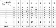
- FIG. 3 is a diagram showing an example of an identification number table of the wireless transmission device according to Embodiment 1 of the present invention.
- FIG. 4 is a diagram showing an example of a reception power table stored in a transmission data information storage unit of the reception terminal according to Embodiment 1 of the present invention.
- 6 is a graph showing a temporal change of an average received power value with movement of the receiving terminal according to Embodiment 1 of the present invention.
- FIG. 1 is a block diagram schematically showing a configuration of a transmission / reception system according to Embodiment 1 of the present invention. It is a figure which shows the example of installation of the radio
- FIG. 6 is a diagram showing an example of a calculation result of a received power average value for each identification number according to Embodiment 1 of the present invention.
- FIG. 6 is a diagram showing an example of a calculation result of a received power average value for each identification number according to Embodiment 1 of the present invention.
- FIG. 6 is a diagram showing an example of a calculation result of a received power average value for each identification number according to Embodiment 1 of the present invention.
- FIG. 6 is a diagram showing an example of a calculation result of a received power average value for each identification number according to Embodiment 1 of the present invention.
- FIG. 6 is a diagram showing an example of a calculation result of a received power average value for each identification number according to Embodiment 1 of the present invention.
- FIG. 6 is a diagram showing an example of a calculation result of a received power average value for each identification number according to Embodiment 1 of the present invention.
- FIG. 6 is a diagram showing an example of a calculation result of a received power average value for each identification number according to Embodiment 1 of the present invention.
- FIG. 6 is a diagram showing an example of a calculation result of a received power average value for each identification number according to Embodiment 1 of the present invention.
- FIG. 3 is a diagram showing an example of a content table stored in a content storage unit of the receiving terminal according to Embodiment 1 of the present invention.
- FIG. 3 is a diagram showing an example of content displayed on a display unit according to Embodiment 1 of the present invention.
- 5 is a flowchart showing a process executed by the receiving terminal according to Embodiment 1 of the present invention.
- 5 is a flowchart showing a position estimation process executed by the receiving terminal according to Embodiment 1 of the present invention.
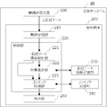
- FIG. 1 is a block diagram schematically showing a configuration of a transmission / reception system according to Embodiment 1 of the present invention.
- a description will be given as a situation in which wireless transmission device 100 is installed in a train, and a passenger (user) in the train has reception terminal 200.
- a transmission / reception system 20 receives a transmission data transmitted from the transmission device 100 and transmission data transmitted from the transmission device 100, estimates a position of the receiving terminal 200, and provides an operation guide of the vehicle. And a receiving terminal 200 for displaying.
- the receiving terminal 200 that has received the transmission data transmitted from the wireless transmission device 100 installed in the train of the train estimates the vehicle on which the user is riding and the position in the vehicle, and determines the position of the user. In response to this, information related to the operation of the train (for example, information indicating the destination of the train) is displayed on the display unit 250 (on the display) of the receiving terminal 200.
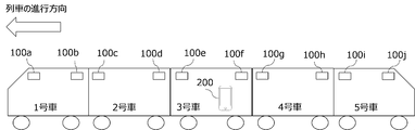
- FIG. 2 is a diagram illustrating an example of installation of the wireless transmission device 100 in a train car.
- FIG. 2 shows a state in which a radio transmission device 100 (that is, radio transmission devices 100a to 100j) is installed in front of and behind each train of a train, taking a 5-car train as an example. I have.
- Receiving terminal 200 receives transmission data transmitted from a plurality of wireless transmission devices 100a to 100j installed in a vehicle that is a plurality of areas. Note that both the first car and the fifth car of the train can be forward, but in the present embodiment, the first car is the front.
- the number of wireless transmission devices installed in each vehicle is described as two, but the number of wireless transmission devices may be three or more.
- the wireless transmission device 100 may be considered as a general term for the wireless transmission devices 100a to 100j. Further, each vehicle on which the wireless transmission device 100 is installed may be represented as an area. In FIG. 2, for example, the first car is an area where the wireless transmission device 100a and the wireless transmission device 100b are installed.
- the wireless transmission device 100 generates transmission data and transmits the transmission data to the receiving terminal 200 at regular intervals.
- the transmission data generated by the wireless transmission device 100 includes device identification information for identifying the wireless transmission device 100, an identification number for identifying an installation position where the wireless transmission device 100 is installed, and contents related to the content to be provided to the reception terminal 200.
- Content information which is information, is included. For example, when displaying information such as the destination of a train on the display unit 250 of the receiving terminal 200, the transmission data includes information about the train as content information.
- the information on trains includes, for example, train type information indicating a train type (normal, express, limited express, etc.), starting station information indicating a starting station, ending station information indicating a ending station, and a next station which is the next stop station of the train. , Train position information indicating the position of the train, and door opening information indicating the door that opens when the vehicle stops.
- the content information may be represented as an arbitrary ID (IDentification).
- IDentification the correspondence between the content information and an arbitrary ID is defined in advance as “CI1” for “station A” and “CI2” for “station B” as the first station information.
- the format of the content information is not limited to this, and may be a numerical value or a text code.
- An arbitrary value indicating the installation position of the wireless transmission device 100 in the train car is set as the identification number.
- an arbitrary value indicating the location of the wireless transmission device 100 in the vehicle and the car number of the installed vehicle is set as the identification number.
- a setting example of the identification number will be described. For example, when the installation location in the vehicle is “front of the vehicle”, the identification number is “odd”, and when the installation location in the vehicle is “rear of the vehicle”, the identification number is “even”.
- the identification number is an odd number
- the car number of the vehicle on which the wireless transmission device 100 is installed is represented by an integer obtained by dividing the identification number by 2 and rounding up the decimal part.
- the identification number is an even number
- the car number of the vehicle on which the wireless transmission device 100 is installed is represented by an integer obtained by dividing the identification number by two.
- FIG. 3 is a diagram showing an example of the identification number table of the wireless transmission device.
- FIG. 3 shows an identification number table indicating an example of identification numbers corresponding to wireless transmission apparatuses 100a to 100j.
- the identification number is “6”
- the car number of the installed vehicle is “car 3”
- the installation location in the vehicle is “rear”.
- another setting method may be used as long as an arbitrary value capable of indicating the car number and the installation position of the vehicle in which the wireless transmission device 100 is installed is set.
- the wireless transmission device 100 may be connected to an information providing device (not shown) that transmits information to be included in transmission data. For example, it may be connected by wire or wirelessly to an information providing device that transmits information about a train to the wireless transmitting device 100. In this case, the radio transmission device 100 receives information about the train from the information providing device at predetermined time intervals, generates transmission data each time, and transmits the transmission data to the reception terminal 200. However, if it is not necessary to generate transmission data each time, the wireless transmission device 100 may repeatedly transmit the same transmission data to the receiving terminal 200 for a certain period without acquiring information from the information providing device. The transmission device 100 has a configuration that is not connected to the information providing device.
- the wireless transmission device 100 transmits transmission data using short-range wireless communication.
- the standard for short-range wireless communication is BLE which is Bluetooth (registered trademark) 4.0.
- BLE uses radio waves in the 2.4 GHz band.
- the communication distance of BLE is a relatively narrow range from 2.5 m to 50 m. For this reason, transmission data can be transmitted within a limited range.
- wireless transmission apparatus 100 periodically transmits transmission data at predetermined intervals.
- the transmission interval is between 20 ms (milliseconds) and 10.24 s (seconds). For this reason, it is assumed that the wireless transmission device sets the transmission interval of the transmission data within the range defined by the BLE standard.
- the wireless transmission device 100 can set the transmission power of the transmission data in a range from -20 dBm to 10 dBm.
- the device identification information is information unique to the wireless transmission device 100.
- the transmission data includes, as device identification information, a specific ID, a flag, or the like capable of distinguishing the wireless transmission device 100 from a smart terminal or a wearable device that transmits and receives data by short-range wireless communication.
- the receiving terminal 200 identifies transmission data transmitted from a device other than the desired wireless transmitting device 100 based on the device identification information, and excludes the transmission data from being processed by the receiving terminal 200. This can prevent erroneous estimation in position estimation at receiving terminal 200.
- the receiving terminal 200 includes a wireless receiving unit 210, a control unit 220, a transmission data information storage unit 230, a content storage unit 240, and a display unit 250.
- the control unit 220 includes a transmission data information analysis unit 221, a position estimation unit 222, and a content acquisition unit 223.
- the control unit 220 may be incorporated in the receiving terminal 200 from the beginning, or may be incorporated in the receiving terminal 200 as an application downloaded from the outside. In this case, a part of the internal memory in the receiving terminal 200 is allocated to the transmission data information storage unit 230 and the content storage unit 240.
- the wireless receiving unit 210 receives the transmission data transmitted from the wireless transmission device 100 and measures the received power when the transmission data is received. Since a plurality of wireless transmission devices 100 are installed, transmission data is received from the plurality of wireless transmission devices 100, and the reception power when receiving the transmission data is measured. Wireless receiving section 210 cannot receive a plurality of transmission data at one time. Therefore, for example, when the reception cycle is 100 ms, the transmission data transmitted from any of the wireless transmission devices 100a to 100j is received every 100 ms. Radio receiving section 210 transmits the transmission data and the measured reception power to control section 220. At this time, the device identification number previously held in the receiving terminal 200 is collated with the device identification information included in the transmission data. As a result of the comparison, if the received transmission data is transmission data received from a terminal other than the wireless transmission device 100, the wireless reception unit 210 does not send the transmission data and the reception power to the control unit 220, and the reception terminal 200 Is completed.
- the wireless receiving unit 210 receives transmission data in accordance with the Bluetooth (registered trademark) 4.0 standard.
- the receiving terminal 200 includes a wireless receiving unit 210 and is capable of performing short-range wireless communication. Specifically, a smartphone, a tablet terminal, or the like can be considered.
- the wireless receiving unit 210 starts receiving the transmission data transmitted from the wireless transmitting device 100. For example, in a case where the wireless transmission device 100 is installed in a train of a train, when the user gets on the vehicle on which the wireless transmission device 100 is installed, reception of transmission data starts.
- the control unit 220 estimates the position of the receiving terminal 200 based on the transmission data and the received power acquired from the wireless receiving unit 210, and acquires the content to be displayed on the display unit 250 of the receiving terminal 200 from the content storage unit 240. Then, the control unit 220 sends the content to the display unit 250.
- the transmission data information analysis unit 221 extracts the identification number and the content information from the transmission data, and transmits the identification number and the reception power to the position estimation unit 222, The information is sent to the content acquisition unit 223. That is, transmission data and reception power are obtained from wireless reception section 210, and an identification number for identifying the installation position of wireless transmission apparatus 100 is extracted from the transmission data.
- the position estimating unit 222 sends the identification number and the received power acquired from the transmission data information analysis unit 221 to the transmission data information storage unit 230. Then, after acquiring the reception history of the reception power for each identification number registered in the transmission data information storage unit 230, the position estimation of the reception terminal 200 is performed, and the position estimation result is sent to the content acquisition unit 223.
- the position estimating unit 222 detects an identification number used for estimating the position of the receiving terminal 200 from among a plurality of identification numbers corresponding to the plurality of reception powers, based on the reception power that is equal to or more than a predetermined threshold among the plurality of reception powers. The number is determined, and the position of the receiving terminal 200 is estimated based on the positional relationship of the number of wireless transmitting devices 100 that has transmitted the transmission data including the identification number used for position estimation. Further, position estimating section 222 obtains the reception histories of the plurality of reception powers from transmission data information storage section 230, calculates the average reception power, and uses the average reception power as the reception power to determine the position of reception terminal 200. presume.
- the transmission data information storage unit 230 stores the identification number and the received power acquired from the position estimation unit 222.
- FIG. 4 is a diagram showing an example of a reception power table stored in the transmission data information storage unit 230.
- “No.” is the number of the received power data stored in the transmission data information storage unit 230.
- the received power data includes the received power and an identification number corresponding to the received power.
- the received power table the received power is registered for each identification number acquired by the transmission data information storage unit 230, and “0” is registered for each No for other identification numbers.
- the received power data to be registered is represented as [received power 1 (identification number 1),..., Received power 10 (identification number 10)] for each No.
- the transmission data information storage unit 230 when the transmission data information storage unit 230 acquires “5” as the identification number and “ ⁇ 69 (dBm)” as the reception power, the transmission data information storage unit 230 stores the reception power data [0 (1) in the reception power table. ), 0 (2), 0 (3), 0 (4), -69 (5), 0 (6), 0 (7), 0 (8), 0 (9), 0 (10)] Will do. That is, the received power corresponding to the identification numbers other than the identification number 5 is 0. In the above description, the identification number not acquired by the transmission data information storage unit 230 only needs to indicate that the identification number has not been acquired.
- the registration of the reception power data to the reception power table is added each time the identification number and the reception power are obtained in the transmission data information storage unit 230. Become.
- the position estimating unit 222 acquires a reception history of a certain number of received powers from the transmission data information storage unit 230 to perform position estimation every time the identification number and the received power are acquired from the transmission data information analysis unit 221. Calculate the received power average value. This is to mitigate the fluctuation of the received power by calculating the average of the received power because the received power may fluctuate greatly depending on the environment around the receiving terminal 200.
- the reception power may be described as a reception power average value.
- the receiving terminal 200 After the start of transmission data reception, until a certain period of time elapses, that is, unless the required number of received power data in the position estimation performed by the position , It is not possible to calculate the average value of the received power and perform position estimation. Therefore, the receiving terminal 200 does not perform position estimation, and ends the processing in the receiving terminal 200.
- the number of pieces of received power data necessary for position estimation performed by position estimating section 222 depends on the time required to calculate the average value of received power. For example, if the receiving terminal 200 receives transmission data every 200 milliseconds (ms), 50 transmission data will be received in 10 seconds. If the average of the received power is calculated every 10 seconds, the number of received power data required for position estimation is 50. In position estimation section 222, the number of pieces of reception power data required for position estimation is set in advance according to the reception cycle of transmission data in reception terminal 200 and the reception power average value calculation time.
- the position estimation unit 222 sends the received power data from the transmission data information storage unit 230 by the number required for position estimation.
- the position estimating unit 222 calculates an average value of the received power for each identification number from the received power data acquired from the transmission data information storage unit 230. It is assumed that the received power average value for each identification number is represented as [average value 1 (identification number 1),..., Average value 10 (identification number 10)]. In the above case, [0 (1),..., 0 (3), -70 (4), -65 (5), -81 (6), 0 (7), 0 (8), -82 (9) , 0 (10)], the received power average value for each identification number is obtained. In calculating the average value, data having a significant received power is used, and data indicating “0” where the received power cannot be measured is not used.
- the position estimating unit 222 sets a predetermined threshold value for estimating whether or not the receiving terminal 200 exists in the area where the wireless transmitting device 100 is installed.
- the value to be set is set in advance based on the reception power measured by the receiving terminal 200 in the area where the wireless transmission device 100 is installed in order to match the environment of the area where the wireless transmission device 100 is installed.
- receiving power “ ⁇ 80 (dBm)” received by receiving terminal 200 from radio transmitting apparatus 100 is set to a predetermined threshold. I do.
- the received power other than “ ⁇ 80 (dBm)” may be set as the predetermined threshold.
- FIG. 5 is a graph showing a change over time in the average received power value with the movement of the receiving terminal. It shows the average value of the received power for each identification number calculated when moving to the transmitting device 100f).
- FIG. 5A is a graph showing a change over time of the received power average value
- FIG. 5B is a diagram showing a state of movement of a user having the receiving terminal 200 in a train car.
- the vertical axis represents the average received power (unit: dBm)
- the horizontal axis represents the elapsed time.
- time t1 is the time when the user possessing the receiving terminal 200 is in front of the car of the third car
- time t2 is the time when the user possessing the receiving terminal 200 is the car of the third car. It is time to be behind.
- the predetermined threshold value is “ ⁇ 80 (dBm)”. If the average received power value is “0”, that is, if the receiving terminal 200 has not received transmission data including the corresponding identification number, it is not shown in the graph.
- the wireless transmission device 100a (1) indicates the wireless transmission device 100a whose identification number is 1. Further, at time t1 and time t2, the wireless transmission devices 100e and 100f corresponding to the identification numbers used for position estimation are shown in black. Further, an arrow indicates a state of movement of the user having the receiving terminal 200 during a time period from the time t1 to the time t2.
- the number of received power averages that are equal to or greater than the predetermined threshold is two, the average of the received power of identification number 5 and the average of the received power of identification number 6.
- the identification numbers of the received power average values that are equal to or greater than the predetermined threshold correspond to the wireless transmission device 100e and the wireless transmission device 100f. Since the wireless transmission device 100e and the wireless transmission device 100f are installed in the same vehicle, it is estimated that the area where the receiving terminal 200 is located is "Car 3". At time t1 in FIG. 5, the reception power average value of the identification number 5 becomes larger than the reception power average value of the identification number 6, so that the position where the reception terminal 200 exists is “in the vicinity of the wireless transmission device 100e having the identification number 5”. ".
- the received power average value that is equal to or greater than the predetermined threshold value is two of the received power average value of the identification number 5 and the received power average value of the identification number 6.
- the identification numbers of the received power average values that are equal to or greater than the predetermined threshold correspond to the wireless transmission device 100e and the wireless transmission device 100f. Since the wireless transmission device 100e and the wireless transmission device 100f are installed in the same vehicle, it is estimated that the area where the receiving terminal 200 is located has not changed from “car 3”. At time t2 in FIG. 5, the reception power average value of the identification number 6 becomes larger than the reception power average value of the identification number 5, and therefore, the position where the receiving terminal 200 is located is “in the vicinity of the wireless transmission device 100f having the identification number 6”. ".
- the position estimation unit 222 estimates that the reception terminal 200 is present in any area where the wireless transmission device 100 is installed if any of the received power average values for each identification number is equal to or greater than a predetermined threshold. That is, in the present embodiment, this is synonymous with presuming that the user carrying the receiving terminal 200 is in a state of riding in any vehicle. Conversely, if any of the received power average values for each identification number is less than the predetermined threshold, it is estimated that the user having the receiving terminal 200 is outside the vehicle.
- the position estimating unit 222 further estimates the area where the receiving terminal 200 exists and the position in the area.
- two wireless transmission devices 100 are installed in one vehicle. Therefore, normally, it is assumed that the reception power average value of the identification numbers set for the two wireless transmission devices 100 installed in the same vehicle is equal to or higher than a predetermined threshold, and the reception power average value is equal to or higher than the predetermined threshold. Two values are obtained. However, when there is a vehicle in which the wireless transmission device 100 cannot be installed due to the layout of the equipment in the vehicle, or when the wireless transmission device 100 is out of order, two received power average values that are equal to or higher than a predetermined threshold are obtained. I can't. On the other hand, a case is also assumed where the average reception power value of the identification number set in the wireless transmission device 100 installed in the vehicle on which the user is not riding is equal to or greater than a predetermined threshold.
- the position estimating unit 222 changes the area where the receiving terminal 200 is present and the number of identification numbers used for estimating the position in the area according to the number of received power average values that are equal to or greater than a predetermined threshold value.
- the position of the receiving terminal 200 is estimated on the basis of the positional relationship in the installation area of the wireless transmission device 100 for the number of transmission data including the identification number to be used.
- the position estimation of the receiving terminal is performed from among the plurality of identification numbers corresponding to the plurality of received power average values. Determine the number of identification numbers to be used. If there are two average received power values that are equal to or greater than the predetermined threshold, and if both are the identification numbers of the wireless transmission devices 100 installed in the same area, the number of identification numbers used for position estimation is two.
- the average value of the received power that is equal to or more than the predetermined threshold is two and the corresponding identification number is the identification number of the wireless transmission device 100 installed in a different area, or the average of the received power that is equal to or more than the predetermined threshold If the value is one, the number of identification numbers used for position estimation is three or more. Note that, depending on the number of wireless transmission devices 100 installed in the area, the index of the number of average reception power values that are equal to or greater than a predetermined threshold may be changed.
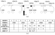
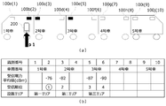
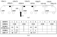
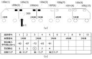
- FIGS. 6 to 12 are diagrams showing an example of a calculation result of the average reception power value for each identification number.
- 6A to FIG. 12A are diagrams showing the arrangement of the wireless transmission devices 100a to 100j in the train car and the position p1 where the receiving terminal 200 exists.
- the target train is the same as in FIG.
- the wireless transmission device 100a (1) indicates the wireless transmission device 100a whose identification number is 1.
- the wireless transmission device 100 corresponding to the identification number used for position estimation is shown in black.
- FIG. 4B shows the calculation results of the average received power, the reception order, and the installation area calculated by each of the wireless transmission devices 100a to 100j (corresponding to the identification numbers 1 to 10) described with reference to FIG.
- a blank portion of the received power average value indicates that the received power is zero.
- the symbol “ ⁇ ” in the number of the reception order indicates that the reception power average value exceeds a predetermined threshold.
- FIG. 6 shows the average received power for each identification number calculated when the user carrying the receiving terminal 200 gets in front of the vehicle in the third car.
- FIG. 7 shows the average received power for each identification number calculated when the user having the receiving terminal 200 moves forward in the fourth car.
- FIG. 8 shows the average received power for each identification number calculated when the user having the receiving terminal 200 gets behind the vehicle in the first car.
- FIG. 9 shows a case where the user having the receiving terminal 200 moves behind the vehicle in the second car, and the wireless transmitting devices 100c and 100d are installed at positions where the wireless transmitting devices 100c and 100d are to be installed.
- 7 shows the average of the received power for each identification number when the wireless transmission device 100c or 100d has failed.
- FIG. 10 shows the average received power for each identification number calculated when the user having the receiving terminal 200 gets in front of the vehicle in the second car.
- FIG. 11 shows the average received power for each identification number calculated when the user having the receiving terminal 200 gets in front of the vehicle in the fifth car.
- FIG. 12 shows a case where the user holding the receiving terminal 200 moves behind the vehicle in the third car, and the wireless transmission devices 100e and 100f are installed at positions where the wireless transmission devices 100e and 100f are to be installed.
- 7 shows the average of the received power for each identification number when the wireless transmission device 100e or 100f is out of order.
- the position estimating unit 222 is configured such that the number of wireless transmission devices 100 equal to the number of identification numbers used for position estimation of the receiving terminal 200 is installed in the same area, or the number of wireless transmission devices 100 is installed in an adjacent area. Based on this, the position of the receiving terminal is estimated.
- the position estimating unit 222 determines that the received power average value that is equal to or greater than the predetermined threshold is two, and both are the identification numbers of the wireless transmission devices 100 installed in the same area (the wireless transmission device installed in the same area). When the number of installed apparatuses 100 is two), it is estimated that the area where the receiving terminal 200 owned by the user is located is the installation area of the wireless transmission apparatus 100. Then, position estimating section 222 selects a larger received power average value from the two received power average values, and moves the vicinity of radio transmitting apparatus 100 having an identification number corresponding to the selected received power average value to receiving terminal 200. Is assumed to be the position where. If the two received power average values match or the difference between the two received power average values is equal to or smaller than a certain value, position estimating section 222 estimates that the position where receiving terminal 200 is located is the center of the area. .
- the wireless transmission devices 100 for the number of identification numbers used for position estimation of the receiving terminal 200 are installed in the same area, and the wireless transmission devices 100 installed in the same area as the number of identification numbers are installed. If the numbers are the same, the position of the receiving terminal 200 is estimated as follows.
- the position estimating unit 222 is located in the same area in the vicinity of the wireless transmission device 100 that has transmitted the transmission data including the identification number corresponding to the maximum received power average value among the received power average values that are equal to or greater than the predetermined threshold value. It is estimated that the receiving terminal 200 is located.
- the position p1 where the receiving terminal 200 exists is ahead of the third car.
- the received power average value that is equal to or larger than the predetermined threshold value is two of the received power average value of the identification number 5 -73 dBm and the received power average value of the identification number 6 -77 dBm.
- the identification numbers 5 and 6 of the received power average value that are equal to or greater than the predetermined threshold correspond to the wireless transmission device 100e and the wireless transmission device 100f.
- Radio transmitting apparatus 100e and radio transmitting apparatus 100f are installed in the same vehicle.
- the position estimating unit 222 estimates that the area where the receiving terminal 200 exists is “car 3”. At the position p1, the received power average value of the identification number 5 becomes larger than the received power average value of the identification number 6, and the position estimating unit 222 determines that the position of the receiving terminal 200 owned by the user is the identification number 5 “wireless transmission”. It is estimated to be “around the device 100e”.
- the two wireless transmission devices that have transmitted the transmission data having one or more received power average values that are equal to or greater than the predetermined threshold and including the identification numbers corresponding to the top two received power average values are located in different areas. The case where the device is installed will be described.
- the position estimating unit 222 determines the identification number of the wireless transmitting apparatus 100 installed in an area where the received power average value that is equal to or more than the predetermined threshold is one or more and the identification numbers corresponding to the top two received power average values are different. In the case of, the top three received power average values are used, and the corresponding identification number of the position of the area where the wireless transmission device 100 is installed is compared.
- the position estimating unit 222 transmits the transmission data including the identification number corresponding to the received power average value equal to or greater than the predetermined threshold (or the identification number corresponding to the largest received power among the plurality of received power average values).
- the area where the wireless transmission device 100 is installed is referred to as a first area.
- Position estimating section 222 sets the area in which radio transmitting apparatus 100 transmitting the transmission data including the identification number corresponding to the second largest received power average value among the plurality of received power average values is set as the second area.
- the position estimating unit 222 sets the area where the wireless transmission device 100 that has transmitted the transmission data including the identification number corresponding to the third largest received power average value among the plurality of received power average values as the third area .
- the position estimating unit 222 estimates that the vicinity of the wireless transmission device 100 installed in the first area and on the second area side is the position where the receiving terminal 200 exists.
- the position p1 where the receiving terminal 200 is located is ahead of the fourth car.
- the received power average value that is equal to or more than the predetermined threshold value is two of the received power average value of the identification number 6 -76 dBm and the received power average value of the identification number 7 -73 dBm.
- the identification number of the average received power value equal to or greater than the predetermined threshold value corresponds to the wireless transmission device 100f and the wireless transmission device 100g.
- the wireless transmission device 100f is installed in the third car (second area).
- the wireless transmission device 100g is installed in the fourth car (first area).
- the wireless transmission device 100i with the identification number 9 having the third largest received power average value is installed in the fifth car (third area) and is adjacent to each other. From this, the position estimating unit 222 estimates that the area where the receiving terminal 200 is located is "No. 4". At the position p1, the wireless transmission device 100f corresponding to the identification number 6 having the second largest average received power is installed in the third car, and therefore the position estimating unit 222 determines that the position where the receiving terminal 200 exists is “wireless”. It is estimated to be “around the transmission device 100 g”.
- the position estimating unit 222 determines that the first area is adjacent to the second area and the third area is located on the second area side and is not adjacent to the first area (the first area, the second area, and the third area). , The first area and the second area are adjacent to each other, and the second area and the third area are adjacent to each other), and the area where the receiving terminal 200 exists is estimated to be the first area. Then, the position estimating unit 222 estimates that the vicinity of the wireless transmission device 100 installed in the first area and on the second area side is the position where the receiving terminal 200 exists.
- the position p1 where the receiving terminal 200 is located is behind the first car.
- the received power average value that is equal to or more than the predetermined threshold value is one of the received power average value of the identification number 2 ⁇ 76 dBm.
- the wireless transmission device 100b corresponding to the identification number 2 is installed in the first car (first area).
- the wireless transmission device 100c corresponding to the identification number 3 having the second largest received power average value is installed in the second car (second area).
- the wireless transmission device 100e corresponding to the identification number 5 having the third largest received power average value is installed in the third car (third area).
- the position estimating unit 222 estimates that the area where the receiving terminal 200 is located is the “first car”. At the position p1, the wireless transmission device 100c corresponding to the identification number 3 having the second largest received power average value is installed in the second car, so the position estimating unit 222 determines that the position where the receiving terminal 200 exists is “wireless”. It is estimated that “the vicinity of the transmitting device 100b”.
- the position estimating unit 222 arranges the first area and the second area in this order.
- the position estimating unit 222 estimates that the area where the receiving terminal 200 exists is an area adjacent to the first area.
- the adjacent area indicates the second area side (the area between the first area and the second area). Then, the position estimating unit 222 estimates that the vicinity of the wireless transmission device 100 installed on the second area side is the position where the receiving terminal 200 is located.
- the position p1 where the receiving terminal 200 is located is behind the No. 2 car.
- the received power average value that is equal to or larger than the predetermined threshold value is one of the received power average value of the identification number 2 ⁇ 76 dBm.
- the wireless transmission device 100b corresponding to the identification number 2 is installed in the first car (first area).
- the wireless transmission device 100e corresponding to the identification number 5 having the second largest average received power is installed in the third car (second area).
- the wireless transmission device 100f corresponding to the identification number 6 having the third largest received power average value is also installed in the third car (second area).
- the position estimating unit 222 estimates that the area where the receiving terminal 200 is located is “car 2”. At the position p1, the wireless transmission device 100f corresponding to the identification number 6 having the third largest received power average value is installed in the third car, so the position estimating unit 222 determines that the position where the receiving terminal 200 exists is “wireless”. It is estimated to be “in the vicinity of the transmitting device 100d”.
- two wireless transmission devices that have transmitted transmission data including one or more received power averages that are equal to or greater than a predetermined threshold and including identification numbers corresponding to the two highest received power averages are located in the same area. The case where the device is installed will be described.
- the position estimating unit 222 determines that the received power average value that is equal to or greater than the predetermined threshold is one, and the identification numbers corresponding to the top two received power average values are the identification numbers of the wireless transmission devices 100 installed in the same area. In some cases, the top four received power averages are used, and the corresponding identification number of the location of the area where the wireless transmission device 100 is installed is compared. This is because the number of installed wireless transmission devices 100 that transmitted transmission data including the identification number corresponding to the received power average value equal to or greater than the predetermined threshold value is greater than the number of installed wireless transmission devices 100 installed in the same area. This is the case when there are few.
- the position estimating unit 222 is configured to transmit the transmission data including the identification number corresponding to the largest received power average value among the plurality of received power average values to the wireless transmission device 100 and the second among the plurality of received power average values.
- the area where the wireless transmission device 100 that has transmitted the transmission data including the identification number corresponding to the larger received power average value is set as the first area.
- Position estimating section 222 sets the area in which radio transmitting apparatus 100 transmitting the transmission data including the identification number corresponding to the third largest received power average value among the plurality of received power average values is set as the second area.
- Position estimating section 222 sets the area where radio transmitting apparatus 100 transmitting the transmission data including the identification number corresponding to the fourth largest received power average value among the plurality of received power average values to be installed as the third area .
- the position estimating unit 222 estimates that the vicinity of the wireless transmission device 100 installed in the first area and on the second area side is the position where the receiving terminal 200 exists.
- the position p1 where the receiving terminal 200 exists is ahead of the second car.
- the received power average value that is equal to or larger than the predetermined threshold is one of the received power average value of the identification number 3 and ⁇ 73 dBm.
- the wireless transmission device 100c corresponding to the identification number 3 and the wireless transmission device 100d corresponding to the identification number 4 having the second largest average received power are installed in the second car (first area).
- the wireless transmission device 100b corresponding to the identification number 2 having the third largest received power average value is installed in the first car (second area).
- the wireless transmission device 100e corresponding to the identification number 5 having the fourth largest received power average value is installed in the third car (third area). From this, the position estimating unit 222 estimates that the area where the receiving terminal 200 is located is “car 2”. At the position p1, the wireless transmission device 100b corresponding to the identification number 2 having the third largest received power average value is installed in the first car, so the position estimating unit 222 determines that the position where the receiving terminal 200 exists is “wireless”. It is estimated to be “in the vicinity of the transmitting device 100c”.
- the position estimating unit 222 determines that the first area is adjacent to the second area and the third area is located on the second area side and is not adjacent to the first area (the first area, the second area, and the third area). , The first area and the second area are adjacent to each other, and the second area and the third area are adjacent to each other), and the area where the receiving terminal 200 exists is estimated to be the first area. Then, the position estimating unit 222 estimates that the vicinity of the wireless transmission device 100 installed in the first area and on the second area side is the position where the receiving terminal 200 exists.
- the position p1 where the receiving terminal 200 exists is ahead of the fifth car.
- the received power average value that is equal to or larger than the predetermined threshold is one of the received power average value of the identification number 9 and -73 dBm.
- the wireless transmission device 100i corresponding to the identification number 9 and the wireless transmission device 100j corresponding to the identification number 10 whose reception power average value is the second largest are installed in the fifth car (first area).
- the wireless transmission device 100h corresponding to the identification number 8 having the third largest received power average value is installed in the fourth car (second area).
- the wireless transmission device 100f corresponding to the identification number 6 having the fourth largest received power average value is installed in the third car (third area). From this, the position estimating unit 222 estimates that the area where the receiving terminal 200 is located is “car 5”. At the position p1, the wireless transmission device 100h corresponding to the identification number 8 whose average received power value becomes the third largest is installed in the fourth car, so the position estimating unit 222 determines that the position where the receiving terminal 200 exists is “wireless”. It is estimated that “the vicinity of the transmitting device 100i”.
- the first area is not adjacent to the second area (the second area, the first area, and the third area are arranged in this order, the second area is not adjacent to the first area, and the first area is not adjacent to the second area). If the area is adjacent), it is estimated that the area where the receiving terminal 200 is located is an area adjacent to the first area.
- the adjacent area indicates the second area side (the area between the first area and the second area). Then, it is estimated that the vicinity of the wireless transmission device 100 installed on the first area side is the position where the receiving terminal 200 exists.
- the position p1 where the receiving terminal 200 is located is behind the No. 3 car.
- the received power average value that is equal to or greater than the predetermined threshold is one of the received power average value of the identification number 7 and ⁇ 76 dBm.
- the wireless transmission device 100g corresponding to the identification number 7 and the wireless transmission device 100h corresponding to the identification number 8 having the second largest average received power are installed in the fourth car (first area).
- the wireless transmission device 100d corresponding to the identification number 4 having the third largest received power average value is installed in the second car (second area).
- the wireless transmission device 100i corresponding to the identification number 9 having the fourth largest received power average value is installed in the fifth car (third area). From this, the position estimating unit 222 estimates that the area where the receiving terminal 200 is located is “Car 3”. At the position p1, the wireless transmission device 100i corresponding to the identification number 9 having the fourth largest received power average value is installed in the fifth car, so the position estimating unit 222 determines that the position where the receiving terminal 200 exists is “wireless”. It is estimated that “the vicinity of the transmitting device 100f”.
- the position estimation unit 222 determines that the position estimation has been completed and sends the position estimation result to the content acquisition unit 223.
- the position estimation result fluctuates in a certain period, the position estimation result is not transmitted to the content acquisition unit 223 while the position estimation result is held, and the subsequent processing in the receiving terminal 200 is not performed.
- the position estimating unit Reference numeral 222 indicates to the content acquisition unit 223 that the area where the receiving terminal 200 is located is “car 3” and the location where the receiving terminal 200 is located is “wireless transmitter 100f” as the position estimation result.
- the position estimating unit 222 determines that the area where the receiving terminal 200 exists is “Car 3” and the receiving terminal 200 The position where 200 exists is maintained as “wireless transmitting device 100e”, and the process of receiving terminal 200 ends.
- the position estimating unit 222 sets in advance a predetermined period for determining whether to send the position estimating result to the content acquiring unit 223.
- the transmission / reception is performed during the stop time of the train, but is changed according to the application destination of the transmission / reception system 20. Further, the number of transmission data that can be received by the receiving terminal 200 per fixed time may be specified.
- the reception terminal 200 by performing the above-described processing in the position estimation unit 222, even if any of the wireless transmission devices 100 is out of order or the wireless transmission device 100 is not installed, the reception terminal 200 The position of the user can be estimated from the received transmission data.
- the content acquisition unit 223 When acquiring the position estimation result from the position estimation unit 222, the content acquisition unit 223 displays the content acquired from the content storage unit 240 on the display unit based on the content information acquired from the transmission data information analysis unit 221 and the position estimation result. Send to 250.
- the content storage unit 240 stores the content displayed by the display unit 250.
- FIG. 13 shows an example of a content table stored in the content storage unit 240.
- the content table indicates the correspondence between the content information and the position with respect to the content. From FIG. 13, for example, the content corresponding to the content information “CI1” and the position corresponding to “P2” is “C2”. Further, the content is character information, a still image, a moving image, sound, or a combination thereof.
- the display unit 250 is an output interface for the content acquired from the content acquiring unit 223, and displays the content based on the position of the receiving terminal 200 and the content information included in the transmission data.
- FIG. 14 shows an example of the content displayed on the display unit 250.
- the display unit 250 displays content corresponding to the position of the user. For example, when the wireless transmission device 100 is installed in the vicinity of the priority seat of the vehicle, a screen as shown in FIG. 14A is displayed on the display of the receiving terminal located away from the priority seat of the first car. You. On the other hand, in the vicinity of the priority seat of the first car, as shown in FIG. 14 (b), a display to which cautions near the priority seat such as "Please switch to the manner mode" is added.
- the wireless transmission device 100 installed in each vehicle transmits transmission data at a fixed cycle after power is turned on.
- the wireless transmission device 100 may be connected to an external terminal (not shown), a transmission data transmission start instruction may be received from the external terminal, and transmission data transmission may be started.
- the transmission power of the transmission data in the wireless transmission device 100 is set so that the reception terminal 200 can receive the transmission data of the wireless transmission device 100 installed in the vehicle.
- the transmission power of the wireless transmission device 100a and the transmission power of the wireless transmission device 100b installed in the first car are the transmission data transmitted from the wireless transmission device 100a and the transmission data transmitted from the wireless transmission device 100b.
- the transmission power is set so as to be able to receive the transmission data transmitted from.
- the wireless transmission device 100 generates transmission data and transmits it to the reception terminal 200. At this time, the wireless transmission device 100 determines the identification number included in the transmission data based on the correspondence between the wireless transmission device 100 and the identification number, and then generates the transmission data.
- wireless transmitting device 100 When connected to an information providing device (not shown), wireless transmitting device 100 newly generates transmission data each time information is acquired from the information providing device.
- the transmission data is generated immediately after the wireless transmission device 100 starts up or after an instruction from an external terminal. In this case, the information included in the transmission data does not change.
- the identification number included in the transmission data is set in advance for each installation position of the wireless transmission device 100.
- FIG. 15 is a flowchart illustrating a process executed by the receiving terminal 200.
- the wireless reception unit 210 receives the transmission data (Step S101), and measures the reception power when receiving the transmission data (Step S102).
- Step S101 the transmission data
- Step S102 measures the reception power when receiving the transmission data
- the process proceeds to step S104. Proceed to processing. If the device identification number of the wireless transmission device 100 held by the receiving terminal 200 in advance does not match the device identification number included in the transmission data (NO in step S103), the process at the receiving terminal 200 ends.
- the transmission data information analysis unit 221 acquires the identification number and the content information included in the transmission data acquired from the wireless reception unit 210 (Step S104). Then, position identification section 222 registers the identification number and the received power in transmission data information storage section 230 (step S105).
- the process proceeds to step S107. If the identification number registered in the transmission data information storage unit 230 and the received power are less than the certain number (NO in step S106), the process in the receiving terminal 200 ends.
- the position estimating unit 222 estimates the position of the receiving terminal 200 from the reception history of the received power for each identification number acquired from the transmission data information storage unit 230 (Step S107).
- the process proceeds to step S109. If the position estimation results do not become the same more than a certain number of times (NO in step S108), the processing in receiving terminal 200 ends with the position estimation result obtained most recently by position estimation section 222 held.
- the content acquisition unit 223 acquires content from the content storage unit 240 based on the content information acquired from the transmission data information analysis unit 221 and the position estimation result acquired from the position estimation unit 222 (step S109). Then, the display unit 250 displays the content acquired by the content acquisition unit 223 (step S110).
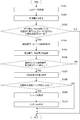
- FIG. 16 is a flowchart illustrating a position estimation process performed by the receiving terminal.
- the position estimating unit 222 calculates an average value of the received power for each identification number in the received power acquired from the transmission data information storage unit 230 (Step S201).
- the process proceeds to step S203. If the received power average value equal to or greater than the predetermined threshold value is zero (NO in step S202), it is estimated that the user having the receiving terminal 200 is outside the vehicle (outside the area) (step S210), and the process ends. I do.
- step S203 There is one or more received power average values that are equal to or greater than a predetermined threshold value, and furthermore, the installation area of the wireless transmission device 100 corresponding to the identification number with the largest received power average value and the identification number with the second largest received power average value Is different from the installation area of the wireless transmission device 100 corresponding to (YES in step S203), the process proceeds to step S204.
- the installation area of the wireless transmission device 100 corresponding to the identification number with the largest received power average value is the same as the installation area of the wireless transmission device 100 with the identification number with the second largest received power average value (step S203) No)
- the process proceeds to step S207.
- position estimating section 222 determines the number of identification numbers to be used for position estimation of receiving terminal 200 to be three, and uses the average of the three highest received power average values. (Step S204). Then, the positional relationship between the installation areas of the wireless transmission devices 100 that transmitted the transmission data including the identification numbers corresponding to the average values of the received powers of the top three is compared (step S205). The position at which the receiving terminal 200 exists is acquired (step S206), and the position estimation processing ends.
- position estimating section 222 determines the number of identification numbers used for estimating the position of receiving terminal 200. The number is determined to be four, and the average value of the four received power average values is used (step S208). Then, the process proceeds to step S205, where the positional relationship of the installation area of the wireless transmission device 100 that has transmitted the transmission data including the identification number corresponding to the average value of the three received powers is compared (step S205). By obtaining the area where the receiving terminal 200 is located and the position where the receiving terminal 200 is located (step S206), the position estimating process ends.
- position estimating section 222 determines the number of identification numbers used for position estimation of receiving terminal 200 to be two, and uses the average of the two highest received power average values. (Step S209). Then, the process proceeds to step S206, where the area where the receiving terminal 200 is present and the position are acquired (step S206), and the position estimation process ends.
- the reception terminal owned by the user 200 position estimates can be made. If the installation area and position of the wireless transmission device 100 corresponding to the identification number at which the reception power of the transmission data received by the reception terminal 200 is the maximum are used as the position estimation result, the wireless transmission device 100 is not installed, or If the transmitting device 100 is out of order, it is estimated that the transmitting device 100 is in a vehicle that is not on board, for example. In the transmission / reception system according to the present embodiment, by comparing the positional relationship of wireless transmission devices 100 that have transmitted the transmission data, it is possible to accurately estimate the position of reception terminal 200 possessed by the user even in the case described above.
- a user who is staying near a priority seat can be warned of a priority seat only.
- a route from the nearest door can be provided at the getting off station.
- the description has been given by limiting to train cars.
- the present invention can be applied even in a situation where a plurality of areas are arranged adjacent to each other in a row. The same effect can be expected.
- 20 ⁇ transmitting / receiving system 100, 100a to 100j ⁇ wireless transmitting device, 200 ⁇ receiving terminal, 210 ⁇ wireless receiving unit, 220 ⁇ control unit, 221 ⁇ transmission data information analysis unit, 222 ⁇ position estimation unit, 223 ⁇ content acquisition unit, 230 ⁇ transmission data information storage unit, 240 content storage unit, 250 display unit.
Landscapes
- Engineering & Computer Science (AREA)
- Physics & Mathematics (AREA)
- General Physics & Mathematics (AREA)
- Radar, Positioning & Navigation (AREA)
- Remote Sensing (AREA)
- Mathematical Physics (AREA)
- Theoretical Computer Science (AREA)
- Computer Networks & Wireless Communication (AREA)
- Signal Processing (AREA)
- Mobile Radio Communication Systems (AREA)
- Position Fixing By Use Of Radio Waves (AREA)
Abstract
受信端末は、付近に無線送信装置が設置されていない場合、又は付近の無線送信装置が故障している場合でも、受信端末の位置の推定を正確に行う。受信端末は、複数の無線送信装置(100)から伝送データを受信し、伝送データを受信した際の受信電力を測定する無線受信部(210)と、無線受信部から伝送データと受信電力とを取得し、無線送信装置の設置位置を識別する識別番号を伝送データから抽出する伝送データ情報解析部(221)と、複数の受信電力のうち所定の閾値以上となる受信電力に基づいて、複数の受信電力に対応する複数の識別番号の中から受信端末の位置推定に使用する識別番号の個数を決定し、位置推定に使用する識別番号が含まれる伝送データを送信した個数の無線送信装置の位置関係に基づいて、受信端末の位置を推定する位置推定部(222)とを備える。
Description
この発明は、ユーザーの位置を推定する受信端末、無線送信装置、送受信システム、受信方法及び送受信方法に関する。
近年、近距離無線通信であるBLE(Bluetooth(登録商標) Low Energy)などの近距離無線通信を利用した屋内での測位技術が知られている。例えば、ユーザーが所持するスマートフォンやタブレット等の携帯情報端末は、無線送信装置からの受信電力を測定する。携帯情報端末が測定した受信電力から携帯情報端末の位置を測定し、携帯情報端末を所持するユーザーの位置に応じた案内や広告等の情報提供を行うシステムが開発されている。このようなシステムにおいては、複数の無線送信装置が存在している中でも精度よくユーザーの位置を推定する必要がある。
そこで、無線送信装置に対応する識別番号が設置されているエリアと関連付けられ、受信したデータに含まれる識別番号より無線送信装置をカウントすることで、ユーザーが滞在しているエリアを推定する情報処理装置がある(例えば、特許文献1参照)。また、この情報処理装置では、測位に要する処理を軽減するために、受信電力に対して所定の閾値を設定している。そして、受信電力が極端に強い場合には、対応する無線送信装置が設置されているエリアにユーザーが滞在していると推定し、受信電力が極端に弱い場合には、無線送信装置が設置されていない、又はエリア外にユーザーが滞在していると推定している。
しかしながら、特許文献1に記載されている装置では、各エリアに設置されている無線送信装置から受信したデータに含まれる識別番号、及び受信電力に基づき、位置推定を行っている。ユーザーが滞在しているエリア付近に無線送信装置が設置されていない場合、又は故障している場合には、ユーザー付近の無線送信装置からデータを取得することができない。このため、ユーザーが滞在しているエリアとは異なるエリアにユーザーが滞在していると推定されてしまう恐れがあり、ユーザーの位置推定を正確に行うことができないという問題があった。
この発明は、上述のような課題を解決するためになされたもので、ユーザーが所持する受信端末の存在するエリア付近に無線送信装置が設置されていない場合、又は無線送信装置が故障している場合でも、ユーザーが所持する受信端末の位置推定を正確に行うことができる受信端末、無線送信装置、送受信システムを提供することを目的とする。
この発明に係る受信端末においては、複数のエリアに設置された複数の無線送信装置から送信される伝送データを受信する受信端末であって、無線送信装置から伝送データを受信し、伝送データを受信した際の受信電力を測定する無線受信部と、無線受信部から伝送データと受信電力とを取得し、無線送信装置の設置位置を識別する識別番号を伝送データから抽出する伝送データ情報解析部と、複数の受信電力のうち所定の閾値以上となる受信電力に基づいて、複数の受信電力に対応する複数の識別番号の中から受信端末の位置推定に使用する識別番号の個数を決定し、位置推定に使用する識別番号が含まれる伝送データを送信した個数の無線送信装置の位置関係に基づいて、受信端末の位置を推定する位置推定部とを備えることを特徴とするものである。
この発明は、ユーザーが所持する受信端末の存在するエリア付近に無線送信装置が設置されていない場合、又は無線送信装置が故障している場合でも、ユーザーが所持する受信端末の位置推定を正確に行うことができる。
以下、図面を参照しながら実施の形態を説明する。以下の図面の記載において、同一又は類似の部分には、同一又は類似の符号を付している。但し、図面は模式的なものであり、各寸法の比率等は現実のものとは異なることに留意すべきである。したがって、具体的な寸法等は以下の説明を参酌して判断すべきものである。また、図面相互間においても互いの寸法の関係や比率が異なる部分が含まれていることは勿論である。
実施の形態1.
図1は、この発明の実施の形態1に係る送受信システムの構成を概略的に示すブロック図である。本実施の形態では、無線送信装置100を列車内に設置し、列車内の乗客(ユーザー)が受信端末200を所持している状況として説明する。図1において、送受信システム20は、伝送データを送信する無線送信装置100と、無線送信装置100から送信された伝送データを受信し、受信端末200の位置を推定した上で、車両の運行案内を表示する受信端末200とを備える。具体的には、列車の車両内に設置された無線送信装置100から送信された伝送データを受信した受信端末200は、ユーザーが乗車している車両や車両内の位置を推定し、ユーザーの位置に応じて列車の運行に関わる情報(例えば、列車の行き先等を示す情報)を受信端末200の表示部250(ディスプレイ上)に表示する。
図1は、この発明の実施の形態1に係る送受信システムの構成を概略的に示すブロック図である。本実施の形態では、無線送信装置100を列車内に設置し、列車内の乗客(ユーザー)が受信端末200を所持している状況として説明する。図1において、送受信システム20は、伝送データを送信する無線送信装置100と、無線送信装置100から送信された伝送データを受信し、受信端末200の位置を推定した上で、車両の運行案内を表示する受信端末200とを備える。具体的には、列車の車両内に設置された無線送信装置100から送信された伝送データを受信した受信端末200は、ユーザーが乗車している車両や車両内の位置を推定し、ユーザーの位置に応じて列車の運行に関わる情報(例えば、列車の行き先等を示す情報)を受信端末200の表示部250(ディスプレイ上)に表示する。
まず、無線送信装置100について説明する。図2は、列車の車両内での無線送信装置100の設置例を示す図である。図2において、5両編成の列車を例にとり、列車の各車両の前方、後方それぞれに1台ずつ、無線送信装置100(すなわち、無線送信装置100a~100j)が設置されている状態を示している。受信端末200は、複数のエリアである車両内に設置された複数の無線送信装置100a~100jから送信される伝送データを受信する。なお、列車の1号車側も5号車側もいずれも前方となり得るが、本実施の形態においては、1号車側を前方とする。本実施の形態では、各車両に設置する無線送信装置の台数を2台として説明するが、無線送信装置の台数が3台以上であってもよい。無線送信装置100は、無線送信装置100a~100jの総称と考えてもよい。また、無線送信装置100が設置される各車両をエリアとして表現してもよい。図2では、例えば、1号車は無線送信装置100a、及び無線送信装置100bが設置されているエリアである。
無線送信装置100は、伝送データを生成し、一定周期で伝送データを受信端末200に送信する。無線送信装置100で生成される伝送データには、無線送信装置100を識別する装置識別情報と、無線送信装置100が設置される設置位置を識別する識別番号と、受信端末200に提供するコンテンツに関する情報であるコンテンツ情報が含まれる。例えば、受信端末200の表示部250に列車の行き先等の情報を表示する場合、伝送データには、コンテンツ情報として列車に関する情報が含まれる。列車に関する情報とは、例えば、列車種別(普通、急行、特急等)を示す列車種別情報、始発駅を示す始発駅情報、終着駅を示す終着駅情報、列車の次の停車駅である次駅を示す次駅情報、列車の位置を示す列車位置情報、そして停車時に開くドアを示すドア開情報等がある。
コンテンツ情報は、任意のID(IDentification)として表してもよい。この場合、始発駅情報として、「駅A」であれば「CI1」、「駅B」であれば「CI2」として、コンテンツ情報と任意のIDとの対応関係が予め定義されているものとする。ただし、コンテンツ情報の形式はこれに限定されず、数値やテキストコードでもよい。
識別番号には、列車の車両内での無線送信装置100の設置位置を示す任意の値を設定する。本実施の形態では、車両内での無線送信装置100の設置箇所、及び設置車両の号車番号を示す任意の値を識別番号として設定する。識別番号の設定例について説明する。例えば、車両内での設置箇所が「車両前方」の場合、識別番号は「奇数」とし、車両内での設置箇所が「車両後方」の場合、識別番号は「偶数」とする。識別番号が奇数の場合、無線送信装置100の設置車両の号車番号は、識別番号を2で割って小数点以下を切り上げた整数で表す。また、識別番号が偶数の場合、無線送信装置100の設置車両の号車番号は、識別番号を2で割った整数で表す。
図3は、無線送信装置の識別番号テーブルの一例を示す図である。図3において、無線送信装置100aから無線送信装置100jに対応する識別番号の例を表す識別番号テーブルを示す。例えば、無線送信装置100fであれば、識別番号は「6」であり、設置車両の号車番号は「3号車」であり、車両内での設置箇所は「後方」となる。識別番号の設定方法としては、無線送信装置100の設置車両の号車番号、及び設置位置を示すことが可能な任意の値が設定されていれば、他の設定方法でも構わない。
無線送信装置100は、伝送データに含むべき情報を送信する情報提供装置(図示せず)と接続されてもよい。例えば、列車に関する情報を無線送信装置100へ送信する情報提供装置と、有線又は無線によって接続されてもよい。この場合、無線送信装置100は、所定の時間間隔で列車に関する情報を情報提供装置から受信し、その都度伝送データを生成し、受信端末200へ送信する。ただし、伝送データをその都度生成する必要がなければ、無線送信装置100は情報提供装置から情報を取得せず、一定期間同じ伝送データを繰り返し受信端末200へ送信してもよく、この場合、無線送信装置100は、情報提供装置と接続されていない構成となる。
無線送信装置100は、近距離無線通信を用いて伝送データを送信する。例えば、近距離無線通信の規格は、Bluetooth(登録商標)4.0であるBLEである。BLEでは、2.4GHz帯の電波が用いられる。また、BLEの通信距離は、2.5mから50mまでの比較的狭い範囲である。このため、限られた範囲内において伝送データを送信することが可能である。また、無線送信装置100は、予め定められた間隔で周期的に伝送データを送信する。BLE規格では、送信間隔は20ms(ミリ秒)から10.24s(秒)までの間である。このため、無線送信装置は、BLE規格に規定されている範囲内で伝送データの送信間隔を設定するものとする。また、無線送信装置100は、伝送データの送信電力を-20dBmから10dBmの範囲で設定可能である。
装置識別情報は、無線送信装置100に対して固有の情報である。伝送データには、装置識別情報として、近距離無線通信によりデータの送受信を行うスマート端末やウェアラブルデバイス等と無線送信装置100とを区別可能である特定のID、又はフラグ等が含まれる。受信端末200は、装置識別情報によって、所望の無線送信装置100以外から送信された伝送データを識別し、受信端末200で行う処理の対象外とする。これにより、受信端末200での位置推定において、誤った推定を防ぐことができる。
次に、受信端末200について説明する。受信端末200は、無線受信部210と、制御部220と、伝送データ情報記憶部230と、コンテンツ記憶部240と、表示部250とを備える。このうち、制御部220は、伝送データ情報解析部221と、位置推定部222と、コンテンツ取得部223とを備える。制御部220は、最初から受信端末200に組み込まれたものでもよいが、外部からダウンロードしたアプリケーションとして受信端末200に組み込まれてもよい。この場合、伝送データ情報記憶部230及びコンテンツ記憶部240には、受信端末200内の内部メモリの一部が割り当てられる。
無線受信部210は、無線送信装置100から送信された伝送データを受信し、伝送データを受信したときの受信電力を測定する。無線送信装置100が複数設置されるので、複数の無線送信装置100から伝送データを受信し、伝送データを受信した際の受信電力を測定することになる。無線受信部210は、一度に複数の伝送データを受信することはできない。このため、例えば、受信周期が100msの場合、100ms毎に無線送信装置100a~100jのいずれかから送信された伝送データを受信する。無線受信部210は、制御部220へ伝送データと測定した受信電力を送る。このとき、予め受信端末200に保持していた装置識別番号と伝送データに含まれる装置識別情報とを照合する。照合した結果、受信した伝送データが無線送信装置100以外の端末から受信した伝送データであった場合、無線受信部210は、制御部220へ伝送データと受信電力とを送らず、受信端末200での処理を終了する。
無線受信部210は、Bluetooth(登録商標)4.0の規格に準拠して伝送データの受信を行う。受信端末200は、無線受信部210を備え、近距離無線通信が可能なものであり、具体的には、スマートフォンやタブレット端末等が考えられる。
受信端末200を所持するユーザーが、無線送信装置100を設置したエリアに入ると、無線受信部210は、無線送信装置100から送信される伝送データの受信を開始する。例えば、列車の車両内に無線送信装置100が設置されている場合、無線送信装置100が設置された車両に乗車すると、伝送データの受信を開始することになる。
制御部220は、無線受信部210から取得した伝送データと受信電力とにより、受信端末200の位置を推定し、受信端末200の表示部250で表示するコンテンツをコンテンツ記憶部240から取得する。そして、制御部220は、表示部250へコンテンツを送る。
制御部220の動作について詳しく説明する。伝送データ情報解析部221は、無線受信部210から伝送データと受信電力とを取得すると、伝送データから識別番号とコンテンツ情報とを抽出し、識別番号と受信電力とを位置推定部222へ、コンテンツ情報をコンテンツ取得部223へ送る。つまり、無線受信部210から伝送データと受信電力とを取得し、無線送信装置100の設置位置を識別する識別番号を伝送データから抽出する。
位置推定部222は、伝送データ情報解析部221から取得した識別番号と受信電力とを伝送データ情報記憶部230へ送る。そして、伝送データ情報記憶部230に登録されている各識別番号に対する受信電力の受信履歴を取得した上で受信端末200の位置推定を行い、位置推定結果をコンテンツ取得部223へ送る。
位置推定部222は、複数の受信電力のうち所定の閾値以上となる受信電力に基づいて、複数の受信電力に対応する複数の識別番号の中から受信端末200の位置推定に使用する識別番号の個数を決定し、位置推定に使用する識別番号が含まれる伝送データを送信した個数分の無線送信装置100の位置関係に基づいて、受信端末200の位置を推定する。また、位置推定部222は、伝送データ情報記憶部230から複数の受信電力の受信履歴を取得して受信電力平均値を算出し、受信電力平均値を受信電力として用いて受信端末200の位置を推定する。
位置推定部222の説明に先立って、伝送データ情報記憶部230について説明する。伝送データ情報記憶部230は、位置推定部222から取得した識別番号と受信電力とを記憶する。
図4は、伝送データ情報記憶部230に格納する受信電力テーブルの一例を示す図である。図4において、「No.」は伝送データ情報記憶部230に格納する受信電力データの番号である。受信電力データには、受信電力と受信電力に対応する識別番号とが含まれる。受信電力テーブルには、伝送データ情報記憶部230で取得した識別番号に対しては受信電力を、それ以外の識別番号に対しては「0」をNo毎に登録する。受信電力テーブルでは、登録する受信電力データをNo毎に[受信電力1(識別番号1),…,受信電力10(識別番号10)]と表す。
例えば、伝送データ情報記憶部230が識別番号として「5」、受信電力として「-69(dBm)」を取得した場合、伝送データ情報記憶部230は、受信電力テーブルに受信電力データ[0(1),0(2),0(3),0(4),-69(5),0(6),0(7),0(8),0(9),0(10)]を登録することになる。つまり、識別番号5以外の識別番号に対応する受信電力は0である。上記では、伝送データ情報記憶部230で取得していない識別番号に対しては、識別番号を取得していないことを示していればよいため、「0」以外の表記でもよい。
位置推定部222では、一定数の受信電力データの受信履歴を使用して位置推定を行う。つまり、位置推定に必要な分だけ受信電力データを登録しておけばよいため、受信電力テーブルでは、受信電力データの登録可能データ数を設定してもよい。登録可能データ数をm(図4のNo.m)とすると、登録可能データ数に登録データ数が達した場合、最も古く登録されたデータ(昇順の場合、図4のNo.1、降順の場合、図4のNo.m)を削除した上で、新規の受信電力データを受信電力テーブル(昇順の場合、図4のNo.m、降順の場合、図4のNo.1)へ登録する。このとき、受信電力テーブルで削除した受信電力データ以外はNoを更新する(昇順の場合、図4のNo=No-1、降順の場合、図4のNo=No+1)。
受信電力テーブルにおいて登録可能データ数が設定されない場合には、伝送データ情報記憶部230で識別番号と受信電力とを取得する度に受信電力テーブルへの受信電力データの登録を追加していくことになる。
位置推定部222に関する説明に戻る。位置推定部222では、伝送データ情報解析部221から識別番号と受信電力とを取得する度に、位置推定を行うために伝送データ情報記憶部230から一定数の受信電力の受信履歴を取得し、受信電力平均値を算出する。これは、受信端末200の周囲の環境によって、受信電力が大きく変動する可能性があるため、受信電力平均値を算出することにより、受信電力の変動を緩和することが目的である。本実施の形態において、受信電力を受信電力平均値として説明する場合がある。
受信端末200において、伝送データ受信開始後は、一定時間が経過するまで、つまり伝送データ情報記憶部230に位置推定部222で行う位置推定での必要数以上の受信電力データが登録されていなければ、受信電力平均値を算出し、位置推定を行うことはできない。このため、受信端末200では位置推定を行わず、受信端末200での処理を終了する。
位置推定部222で行う位置推定のために必要な受信電力データのデータ数は、受信電力平均値の算出に要する時間に依存する。例えば、受信端末200が200ミリ秒(ms)ごとに伝送データを受信する場合、10秒間では50個の伝送データを受信することになる。受信電力平均値の算出を10秒間ずつ行う場合、位置推定に必要な受信電力データのデータ数は50個となる。位置推定部222では、受信端末200における伝送データの受信周期、及び受信電力平均値算出時間に応じて、予め、位置推定で必要な受信電力データのデータ数を設定しておくこととする。
伝送データ情報記憶部230に位置推定を行うための必要数以上の受信電力データが登録されている場合、位置推定部222は、伝送データ情報記憶部230から位置推定に必要な数だけ受信電力データを取得する。例えば、位置推定に必要な受信電力データのデータ数が「50」であり、図4のNo.mを「m=50」とする場合、受信電力テーブルにNo.mのデータを登録した後に位置推定部222で取得する受信電力データを[[受信電力1(識別番号1),…,受信電力10(識別番号10)]No.1,…,[受信電力1(識別番号1),…,受信電力10(識別番号10)]No.m]と表す。図4のような受信電力テーブルから、[[0(1),…,0(4),-69(5),0(6),…,0(10)]1,[0(1),…,0(5),-84(6),0(7),…,0(10)]2,…,[0(1),…,0(4),-57(5),0(6),…,0(10)]m]を取得することになる。
位置推定部222では、伝送データ情報記憶部230から取得した受信電力データから識別番号ごとに受信電力平均値を算出する。識別番号ごとの受信電力平均値を[平均値1(識別番号1),…,平均値10(識別番号10)]と表すとする。上述の場合、[0(1),…,0(3),-70(4),-65(5),-81(6),0(7),0(8),-82(9),0(10)]のように識別番号ごとの受信電力平均値を取得することになる。なお、平均値を算出するにあたり、受信電力が有意な値であるデータを用い、受信電力が測定できない「0」を示すデータについては用いない。
位置推定部222では、無線送信装置100が設置されているエリア内に受信端末200が存在するかどうかを推定する所定の閾値を設定しておく。設定する値は、無線送信装置100が設置されるエリアの環境に合わせるため、予め、無線送信装置100が設置されるエリアにおいて、受信端末200で計測した受信電力に基づいて設定される。本実施の形態では一例として、受信端末200と無線送信装置100とが同じエリアにある場合に、受信端末200が無線送信装置100から受信する受信電力「-80(dBm)」を所定の閾値とする。「-80(dBm)」以外の受信電力を所定の閾値としてもよい。
ここで、受信端末200の位置と受信端末200が無線送信装置100a~100jから伝送データを受信したときの受信電力平均値との関係について説明する。図5は、受信端末の移動に伴う受信電力平均値の時間変化を示したグラフであり、受信端末200を所持したユーザーが、3号車内で車両前方(無線送信装置100e)から車両後方(無線送信装置100f)へ移動したときに算出された識別番号ごとの受信電力平均値を示している。図5(a)は、受信電力平均値の時間変化を示したグラフで、図5(b)は列車の車両内における受信端末200を所持したユーザーの移動の様子を示した図である。図5(a)において、縦軸は受信電力平均値(単位はdBm)、横軸は経過時間である。図5(a)及び図5(b)において、時刻t1は、受信端末200を所持したユーザーが3号車の車両前方にいる時刻、時刻t2は、受信端末200を所持したユーザーが3号車の車両後方にいる時刻である。
図5(a)において、所定の閾値は「-80(dBm)」とする。受信電力平均値が「0」であった場合、つまり、受信端末200が対応する識別番号を含む伝送データを受信していない場合、グラフに図示していない。図5(b)において、無線送信装置100a(1)は識別番号が1である無線送信装置100aを示している。また、時刻t1及び時刻t2において、位置推定に使用する識別番号に対応する無線送信装置100e、100fを黒色で示している。さらに、矢印は時刻t1から時刻t2の時間帯に受信端末200を所持したユーザーの移動の様子を示している。
図5(a)より、時刻t1において、所定の閾値以上となる受信電力平均値は、識別番号5の受信電力平均値と識別番号6の受信電力平均値との2個となる。また、所定の閾値以上となる受信電力平均値の識別番号は、無線送信装置100eと無線送信装置100fに対応している。無線送信装置100eと無線送信装置100fとは、同じ車両に設置されていることから、受信端末200の存在するエリアが「3号車」であると推定する。図5の時刻t1では、識別番号5の受信電力平均値が識別番号6の受信電力平均値より大きくなるため、受信端末200が存在する位置は、識別番号が5である「無線送信装置100e付近」であると推定する。
また、受信端末200を所持したユーザーの移動した時刻t2においても、所定の閾値以上となる受信電力平均値は、識別番号5の受信電力平均値と識別番号6の受信電力平均値との2個となる。また、所定の閾値以上となる受信電力平均値の識別番号は、無線送信装置100eと無線送信装置100fに対応している。無線送信装置100eと無線送信装置100fは、同じ車両に設置されていることから、受信端末200の存在するエリアが「3号車」から変化していないと推定する。図5の時刻t2では、識別番号6の受信電力平均値が識別番号5の受信電力平均値より大きくなるため、受信端末200が存在する位置は、識別番号が6である「無線送信装置100f付近」であると推定する。
位置推定部222では、識別番号ごとの受信電力平均値のいずれかが所定の閾値以上であれば、受信端末200は、無線送信装置100が設置されたいずれかのエリアに存在すると推定する。つまり、本実施の形態では、受信端末200を所持したユーザーがいずれかの車両に乗車している状態であると推定されることと同義である。反対に、識別番号ごとの受信電力平均値のいずれもが所定の閾値未満であれば、受信端末200を所持したユーザーは車両外にいると推定される
無線送信装置100が設置されたいずれかのエリアに受信端末200が存在すると推定されると、位置推定部222では、さらに受信端末200が存在するエリア、及びエリア内での位置を推定する。
本実施の形態では、1つの車両に2台の無線送信装置100が設置されている。そのため、通常であれば、同じ車両に設置された2台の無線送信装置100に設定された識別番号の受信電力平均値が所定の閾値以上になると想定され、所定の閾値以上となる受信電力平均値が2個得られる。しかしながら、車両内設備のレイアウトの関係で無線送信装置100が設置不可能な車両がある場合、又は無線送信装置100が故障している場合、所定の閾値以上となる受信電力平均値が2個得られない。一方、ユーザーが乗車していない車両に設置された無線送信装置100に設定された識別番号の受信電力平均値が所定の閾値以上になる場合も想定される。
そこで、位置推定部222では、所定の閾値以上となる受信電力平均値の個数によって、受信端末200が存在するエリア、及びエリア内の位置推定に使用する識別番号の個数を変更し、位置推定に使用する識別番号が含まれる伝送データを送信した個数分の無線送信装置100の設置エリア内での位置関係に基づいて、受信端末200の位置推定を行う。
本実施の形態では、複数の受信電力平均値のうち所定の閾値以上となる受信電力平均値に基づいて、複数の受信電力平均値に対応する複数の識別番号の中から受信端末の位置推定に使用する識別番号の個数を決定する。所定の閾値以上となる受信電力平均値が2個であり、どちらも同じエリアに設置された無線送信装置100の識別番号であれば、位置推定に使用する識別番号の個数を2個とする。また、所定の閾値以上となる受信電力平均値が2個であり、対応する識別番号が異なるエリアに設置された無線送信装置100の識別番号である場合、又は所定の閾値以上となる受信電力平均値が1個である場合、位置推定に使用する識別番号の個数を3個以上とする。なお、エリア内に設置される無線送信装置100の台数によっては、所定の閾値以上となる受信電力平均値の個数の指標を変更してもよい。
図6~図12は、識別番号ごとの受信電力平均値の算出結果の一例を示す図である。図6~図12において、図(a)は、列車の車両内における無線送信装置100a~100jの配置、及び受信端末200が存在する位置p1を示した図である。対象とする列車は図2と同様である。無線送信装置100a(1)は識別番号が1である無線送信装置100aを示している。位置推定に使用する識別番号に対応する無線送信装置100を黒色で示している。図(b)は、図4を用いて説明した無線送信装置100a~100j(識別番号1~10に対応)の各々で算出された受信電力平均値の算出結果、受信順位、及び設置エリアを示した図である。受信電力平均値が空白となっている箇所は受信電力が0であることを表している。また、受信順位の数字に〇印が付いていることは、受信電力平均値が所定の閾値を超えていることを表している。
図6は、受信端末200を所持したユーザーが、3号車内の車両前方に乗車した場合に算出された識別番号ごとの受信電力平均値を示している。図7は、受信端末200を所持したユーザーが、4号車内の車両前方に移動した場合に算出された識別番号ごとの受信電力平均値を示している。図8は、受信端末200を所持したユーザーが、1号車内の車両後方に乗車した場合に算出された識別番号ごとの受信電力平均値を示している。図9は、受信端末200を所持したユーザーが、2号車内の車両後方に移動した場合であって、無線送信装置100c,100dが設置されるはずの位置に無線送信装置100c,100dが設置されていない場合、又は無線送信装置100c,100dが故障している場合の識別番号ごとの受信電力平均値を示している。
図10は、受信端末200を所持したユーザーが、2号車内の車両前方に乗車した場合に算出された識別番号ごとの受信電力平均値を示している。図11は、受信端末200を所持したユーザーが、5号車内の車両前方に乗車した場合に算出された識別番号ごとの受信電力平均値を示している。図12は、受信端末200を所持したユーザーが、3号車内の車両後方に移動した場合であって、無線送信装置100e,100fが設置されるはずの位置に無線送信装置100e,100fが設置されていない場合、又は無線送信装置100e,100fが故障している場合の識別番号ごとの受信電力平均値を示している。
図6~図12で示した受信電力平均値の具体例の説明を加えながら、受信端末200が存在する位置の位置推定について説明する。
位置推定部222は、受信端末200の位置推定に使用する識別番号の個数分の無線送信装置100が同一のエリアに設置されること、又は個数分の無線送信装置が隣接するエリアに設置されることに基づいて、受信端末の位置を推定する。
まず、所定の閾値以上となる受信電力平均値が2個の場合で、これら2個に対応する識別番号が含まれる伝送データを送信した2個の無線送信装置が同じエリアに設置された場合について説明する。
位置推定部222は、所定の閾値以上となる受信電力平均値が2個であり、どちらも同じエリアに設置された無線送信装置100の識別番号である場合(同じエリア内に設置される無線送信装置100の設置数が2個の場合)、ユーザーが所持する受信端末200の存在するエリアが無線送信装置100の設置エリアであると推定する。そして、位置推定部222は、2個の受信電力平均値のうちでより大きくなる受信電力平均値を選択し、選択した受信電力平均値に対応する識別番号の無線送信装置100付近を受信端末200が存在する位置であると推定する。位置推定部222は、2個の受信電力平均値が一致する場合、又は2個の受信電力平均値の差が一定値以下の場合、受信端末200が存在する位置がエリア中央であると推定する。
このように、受信端末200の位置推定に使用する識別番号の個数分の無線送信装置100が同一のエリアに設置され、識別番号の個数と同一のエリア内に設置される無線送信装置100の設置数とが同じである場合、次のように受信端末200の位置推定を行う。位置推定部222は、同一のエリアにおいて、所定の閾値以上となる受信電力平均値のうち最大となる受信電力平均値に対応する識別番号が含まれる伝送データを送信した無線送信装置100の付近に受信端末200が位置すると推定する。
このような推定を行う場合の具体例について図6を用いて説明する。図6(a)に示すように、受信端末200が存在する位置p1は、3号車の車両前方である。図6(b)に示すように、位置p1において、所定の閾値以上となる受信電力平均値は、識別番号5の受信電力平均値-73dBmと識別番号6の受信電力平均値-77dBmとの2個となる。また、所定の閾値以上となる受信電力平均値の識別番号5,6は、無線送信装置100eと無線送信装置100fとに対応している。無線送信装置100eと無線送信装置100fとは、同じ車両に設置されている。このことから、位置推定部222は、受信端末200の存在するエリアが「3号車」である推定する。位置p1において、識別番号5の受信電力平均値が識別番号6の受信電力平均値より大きくなるため、位置推定部222は、ユーザーが所有する受信端末200の位置が識別番号5である「無線送信装置100e付近」であると推定する。
次に、所定の閾値以上となる受信電力平均値が1個以上で、受信電力平均値の上位2個に対応する識別番号が含まれる伝送データを送信した2個の無線送信装置が異なるエリアに設置された場合について説明する。
位置推定部222は、所定の閾値以上となる受信電力平均値が1個以上であり、受信電力平均値の上位2個に対応する識別番号が異なるエリアに設置された無線送信装置100の識別番号である場合、受信電力平均値の上位3個を使用し、対応する識別番号である無線送信装置100が設置されたエリアの位置を比較する。
位置推定部222は、所定の閾値以上となる受信電力平均値に対応する識別番号(又は複数の受信電力平均値のうち一番目に大きい受信電力に対応する識別番号)が含まれる伝送データを送信した無線送信装置100が設置されるエリアを第一エリアとする。位置推定部222は、複数の受信電力平均値のうちニ番目に大きい受信電力平均値に対応する識別番号が含まれる伝送データを送信した無線送信装置100が設置されるエリアを第ニエリアとする。位置推定部222は、複数の受信電力平均値のうち三番目に大きい受信電力平均値に対応する識別番号が含まれる伝送データを送信した無線送信装置100が設置されるエリアを第三エリアとする。
位置推定部222は、第一エリアが第ニエリアと第三エリアとに隣接する場合(第二エリア、第一エリア、第三エリアの順に並び、第二エリアと第一エリアとが隣接し、第一エリアと第三エリアとが隣接する場合)、受信端末200の存在するエリアが第一エリアであると推定する。そして、位置推定部222は、第一エリアであって、第ニエリア側に設置されている無線送信装置100付近を受信端末200が存在する位置であると推定する。なお、本実施の形態において各エリアの並び順について説明するが、並ぶ順番が車両前方からでも車両後方からでもどちらでも良い。また、並ぶ順番が逆の順番になっても、受信端末200が存在する位置を同じように推定することができる。
このような推定を行う場合の具体例について図7を用いて説明する。図7(a)に示すように、受信端末200が存在する位置p1は、4号車の車両前方である。図7(b)に示すように、位置p1において、所定の閾値以上となる受信電力平均値は、識別番号6の受信電力平均値-76dBmと識別番号7の受信電力平均値-73dBmとの2個となる。また、所定の閾値以上となる受信電力平均値の識別番号は、無線送信装置100fと無線送信装置100gとに対応している。無線送信装置100fは、3号車(第二エリア)に設置されている。無線送信装置100gは、4号車(第一エリア)に設置されている。受信電力平均値が3番目に大きい識別番号9の無線送信装置100iは5号車(第三エリア)に設置されており、それぞれ隣接している。このことから、位置推定部222は、受信端末200の存在するエリアが「4号車」であると推定する。位置p1において、受信電力平均値が2番目に大きくなる識別番号6に対応する無線送信装置100fは3号車に設置されているため、位置推定部222は、受信端末200が存在する位置が「無線送信装置100g付近」であると推定する。
位置推定部222は、第一エリアが第二エリアと隣接し、第三エリアが第二エリア側に位置した状態で、第一エリアとは隣接しない場合(第一エリア、第ニエリア、第三エリアの順に並び、第一エリアと第ニエリアとが隣接し、第ニエリアと第三エリアとが隣接する場合)、受信端末200の存在するエリアが第一エリアであると推定する。そして、位置推定部222は、第一エリアであって、第ニエリア側に設置されている無線送信装置100付近を受信端末200が存在する位置であると推定する。
このような推定を行う場合の具体例について図8を用いて説明する。図8(a)に示すように、受信端末200が存在する位置p1は、1号車の車両後方である。図8(b)に示すように、位置p1において、所定の閾値以上となる受信電力平均値は、識別番号2の受信電力平均値-76dBmの1個である。識別番号2に対応する無線送信装置100bは1号車(第一エリア)に設置されている。受信電力平均値が2番目に大きくなる識別番号3に対応する無線送信装置100cは2号車(第ニエリア)に設置されている。受信電力平均値が3番目に大きくなる識別番号5に対応する無線送信装置100eは3号車(第三エリア)に設置されている。このことから、位置推定部222は、受信端末200の存在するエリアが「1号車」であると推定する。位置p1において、受信電力平均値が2番目に大きくなる識別番号3に対応する無線送信装置100cは2号車に設置されているため、位置推定部222は、受信端末200が存在する位置が「無線送信装置100b付近」であると推定する。
位置推定部222は、第一エリア、第ニエリアの順に並び、第一エリアが第二エリアと隣接しない場合、受信端末200の存在するエリアが第一エリアの隣エリアであると推定する。ここで、隣エリアとは、第ニエリア側(第一エリアと第ニエリアとの間のエリア)を指す。そして、位置推定部222は、隣エリアであって、第ニエリア側に設置されている無線送信装置100付近を受信端末200が存在する位置であると推定する。
このような推定を行う場合の具体例について図9を用いて説明する。図9(a)に示すように、受信端末200が存在する位置p1は、2号車の車両後方である。図9(b)に示すように、位置p1において、所定の閾値以上となる受信電力平均値は、識別番号2の受信電力平均値-76dBmの1個である。識別番号2に対応する無線送信装置100bは1号車(第一エリア)に設置されている。受信電力平均値が2番目に大きくなる識別番号5に対応する無線送信装置100eは3号車(第ニエリア)に設置されている。受信電力平均値が3番目に大きくなる識別番号6に対応する無線送信装置100fも3号車(第ニエリア)に設置されている。このことから、位置推定部222は、受信端末200の存在するエリアが「2号車」であると推定する。位置p1において、受信電力平均値が3番目に大きくなる識別番号6に対応する無線送信装置100fは3号車に設置されているため、位置推定部222は、受信端末200が存在する位置が「無線送信装置100d付近」であると推定する。
次に、所定の閾値以上となる受信電力平均値が1個以上で、受信電力平均値の上位2個に対応する識別番号が含まれる伝送データを送信した2個の無線送信装置が同じエリアに設置された場合について説明する。
位置推定部222は、所定の閾値以上となる受信電力平均値が1個であり、受信電力平均値の上位2個に対応する識別番号が同じエリアに設置された無線送信装置100の識別番号である場合、受信電力平均値の上位4個を使用し、対応する識別番号である無線送信装置100が設置されたエリアの位置を比較する。これは、所定の閾値以上となる受信電力平均値に対応する識別番号が含まれる伝送データを送信した無線送信装置100の設置数が、同じエリア内に設置される無線送信装置100の設置数より少ない場合である。
位置推定部222は、複数の受信電力平均値のうち一番目に大きい受信電力平均値に対応する識別番号が含まれる伝送データを送信した無線送信装置100と複数の受信電力平均値のうちニ番目に大きい受信電力平均値に対応する識別番号が含まれる伝送データを送信した無線送信装置100とが設置されるエリアを第一エリアとする。位置推定部222は、複数の受信電力平均値のうち三番目に大きい受信電力平均値に対応する識別番号が含まれる伝送データを送信した無線送信装置100が設置されるエリアを第ニエリアとする。位置推定部222は、複数の受信電力平均値のうち四番目に大きい受信電力平均値に対応する識別番号が含まれる伝送データを送信した無線送信装置100が設置されるエリアを第三エリアとする。
位置推定部222は、第一エリアが第ニエリアと第三エリアとに隣接する場合(第二エリア、第一エリア、第三エリアの順に並び、第二エリアと第一エリアとが隣接し、第一エリアと第三エリアとが隣接する場合)、受信端末200の存在するエリアが第一エリアであると推定する。そして、位置推定部222は、第一エリアであって、第ニエリア側に設置されている無線送信装置100付近を受信端末200が存在する位置であると推定する。
このような推定を行う場合の具体例について図10を用いて説明する。図10(a)に示すように、受信端末200が存在する位置p1は、2号車の車両前方である。図10(b)に示すように、位置p1において、所定の閾値以上となる受信電力平均値は、識別番号3の受信電力平均値-73dBmの1個である。識別番号3に対応する無線送信装置100c、及び受信電力平均値が2番目に大きくなる識別番号4に対応する無線送信装置100dは2号車(第一エリア)に設置されている。受信電力平均値が3番目に大きくなる識別番号2に対応する無線送信装置100bは1号車(第ニエリア)に設置されている。受信電力平均値が4番目に大きくなる識別番号5に対応する無線送信装置100eは3号車(第三エリア)に設置されている。このことから、位置推定部222は、受信端末200の存在するエリアが「2号車」であると推定する。位置p1において、受信電力平均値が3番目に大きくなる識別番号2に対応する無線送信装置100bは1号車に設置されているため、位置推定部222は、受信端末200が存在する位置が「無線送信装置100c付近」であると推定する。
位置推定部222は、第一エリアが第二エリアと隣接し、第三エリアが第二エリア側に位置した状態で、第一エリアとは隣接しない場合(第一エリア、第ニエリア、第三エリアの順に並び、第一エリアと第ニエリアとが隣接し、第ニエリアと第三エリアとが隣接する場合)、受信端末200の存在するエリアが第一エリアであると推定する。そして、位置推定部222は、第一エリアであって、第ニエリア側に設置されている無線送信装置100付近を受信端末200が存在する位置であると推定する。
このような推定を行う場合の具体例について図11を用いて説明する。図11(a)に示すように、受信端末200が存在する位置p1は、5号車の車両前方である。図11(b)に示すように、位置p1において、所定の閾値以上となる受信電力平均値は、識別番号9の受信電力平均値-73dBmの1個である。識別番号9に対応する無線送信装置100i、及び受信電力平均値が2番目に大きくなる識別番号10に対応する無線送信装置100jは5号車(第一エリア)に設置されている。受信電力平均値が3番目に大きくなる識別番号8に対応する無線送信装置100hは4号車(第ニエリア)に設置されている。受信電力平均値が4番目に大きくなる識別番号6に対応する無線送信装置100fは3号車(第三エリア)に設置されている。このことから、位置推定部222は、受信端末200の存在するエリアが「5号車」であると推定する。位置p1において、受信電力平均値が3番目に大きくなる識別番号8に対応する無線送信装置100hは4号車に設置されているため、位置推定部222は、受信端末200が存在する位置が「無線送信装置100i付近」であると推定する。
位置推定部222は、第一エリアが第二エリアと隣接しない場合(第ニエリア、第一エリア、第三エリアの順に並び、第ニエリアと第一エリアとが隣接せず、第一エリアと第三エリアとが隣接する場合)、受信端末200の存在するエリアが第一エリアの隣エリアであると推定する。ここで、隣エリアとは、第ニエリア側(第一エリアと第ニエリアとの間のエリア)を指す。そして、隣エリアであって、第一エリア側に設置されている無線送信装置100付近を受信端末200が存在する位置であると推定する。
このような推定を行う場合の具体例について図12を用いて説明する。図12より、図12(a)に示すように、受信端末200が存在する位置p1は、3号車の車両後方である。図12(b)に示すように、位置p1において、所定の閾値以上となる受信電力平均値は、識別番号7の受信電力平均値-76dBmの1個である。識別番号7に対応する無線送信装置100g、及び受信電力平均値が2番目に大きくなる識別番号8に対応する無線送信装置100hは4号車(第一エリア)に設置されている。受信電力平均値が3番目に大きくなる識別番号4に対応する無線送信装置100dは2号車(第ニエリア)に設置されている。受信電力平均値が4番目に大きくなる識別番号9に対応する無線送信装置100iは5号車(第三エリア)に設置されている。このことから、位置推定部222は、受信端末200の存在するエリアが「3号車」であると推定する。位置p1において、受信電力平均値が4番目に大きくなる識別番号9に対応する無線送信装置100iは5号車に設置されているため、位置推定部222は、受信端末200が存在する位置が「無線送信装置100f付近」であると推定する。
図1のブロック図の説明に戻る。位置推定部222では、位置推定結果が一定期間変動しない場合、位置推定が完了したとして、コンテンツ取得部223へ位置推定結果を送る。一方、位置推定結果が一定期間において変動している場合、位置推定結果を保持した状態で、コンテンツ取得部223へ位置推定結果を送らず、受信端末200における以降の処理は行わない。
例えば、位置推定結果として、受信端末200の存在するエリアが「3号車」であり、受信端末200が存在する位置が「無線送信装置100f」といった位置推定結果を一定期間得た場合、位置推定部222は、コンテンツ取得部223へ位置推定結果として受信端末200の存在するエリアが「3号車」であり、受信端末200が存在する位置が「無線送信装置100f」を送る。受信端末200の存在するエリアが「3号車」であり、受信端末200が存在する位置が「無線送信装置100f」である位置推定結果を得た後、受信端末200の存在するエリアが「3号車」であり、受信端末200が存在する位置が「無線送信装置100e」という位置推定結果を得た場合、位置推定部222は、受信端末200の存在するエリアが「3号車」であり、受信端末200が存在する位置が「無線送信装置100e」といった状態を保持し、受信端末200の処理を終了する。
ここで、位置推定部222では、位置推定結果をコンテンツ取得部223へ送るかどうか判断する一定期間を予め設定しておく。本実施の形態では、列車停車時間内で行うこととするが、送受信システム20の適用先に応じて変更するものとする。また、受信端末200で一定時間あたりに受信可能な伝送データ数を指定してもよい。
以上説明したとおり、位置推定部222において、上述の処理を行うことにより、いずれかの無線送信装置100が故障している場合、又は無線送信装置100が設置されていない場合でも、受信端末200で受信した伝送データからユーザーの位置を推定することができる。
コンテンツ取得部223は、位置推定部222から位置推定結果を取得すると、伝送データ情報解析部221から取得したコンテンツ情報、及び位置推定結果に基づいて、コンテンツ記憶部240から取得したコンテンツを、表示部250へ送る。
コンテンツ記憶部240は、表示部250が表示するコンテンツを記憶する。図13に、コンテンツ記憶部240に格納するコンテンツテーブルの一例を示す。コンテンツテーブルは、コンテンツに対して、コンテンツ情報と位置との対応を示したものである。図13より、例えば、コンテンツ情報が「CI1」、位置が「P2」に対応するコンテンツは「C2」となる。また、コンテンツとは、文字情報、静止画像、動画画像、音声、又はこれらの組み合わせである。
表示部250は、コンテンツ取得部223から取得したコンテンツの出力インタフェースであり、受信端末200の位置と伝送データに含まれるコンテンツ情報とに基づいたコンテンツを表示する。図14に、表示部250に表示されるコンテンツの一例を示す。表示部250には、ユーザーの位置に応じたコンテンツが表示される。例えば、車両の優先席付近に無線送信装置100が設置されている場合に、1号車の優先席とは離れた位置に存在する受信端末のディスプレイでは図14(a)のような画面が表示される。一方、1号車の優先席付近では、図14(b)のように、「マナーモードに切り替えてください」のような、優先席付近での注意事項が付加された表示となる。
次に、本実施の形態に関わる送受信システム20の各装置の動作について説明する。まず、各車両に設置される無線送信装置100は、電源投入後に一定周期で伝送データを送信する。ただし、無線送信装置100と外部端末(図示せず)とを接続し、伝送データの送信開始指示を外部端末から受信し、伝送データの送信を開始してもよい。無線送信装置100において伝送データの送信電力は、車両内に設置されている無線送信装置100の伝送データを受信端末200が受信できるように設定される。例えば、1号車に設置される無線送信装置100aの送信電力と無線送信装置100bの送信電力とは、1号車に存在する受信端末200が無線送信装置100aから送信される伝送データと無線送信装置100bから送信される伝送データとを受信可能であるように送信電力に設定される。
無線送信装置100は、伝送データを生成し、受信端末200へ送信する。このとき、無線送信装置100は、無線送信装置100と識別番号との対応に基づいて、伝送データに含む識別番号を決定した上で、伝送データを生成する。無線送信装置100は、情報提供装置(図示せず)と接続される場合、情報提供装置から情報を取得するたびに、伝送データを新たに生成する。無線送信装置100が情報提供装置と接続されない場合、無線送信装置100が起動した直後、又は外部端末からの指示後に伝送データを生成する。この場合、伝送データに含まれる情報が変化することはない。また、伝送データに含む識別番号は、無線送信装置100の設置位置ごとに予め設定しておく。
受信端末200の動作について、フローチャートを用いて説明する。図15は、受信端末200が実行する処理を示すフローチャートである。無線受信部210は、伝送データを受信し(ステップS101)、伝送データ受信時の受信電力を測定する(ステップS102)。ここで、受信端末200が予め保持していた無線送信装置100の装置識別番号と、伝送データに含まれる無線送信装置100の装置識別番号とが一致する場合(ステップS103でYES)、ステップS104の処理へ進む。受信端末200が予め保持していた無線送信装置100の装置識別番号と、伝送データに含まれる装置識別番号とが一致しない場合(ステップS103でNO)、受信端末200での処理を終了する。
伝送データ情報解析部221は、無線受信部210から取得した伝送データに含まれる識別番号とコンテンツ情報とを取得する(ステップS104)。そして、位置推定部222にて識別番号と受信電力とを伝送データ情報記憶部230に登録する(ステップS105)。ここで、伝送データ情報記憶部230にて登録されている識別番号、及び受信電力が一定数以上である場合(ステップS106でYES)、ステップS107の処理へ進む。伝送データ情報記憶部230にて登録されている識別番号、及び受信電力が一定数未満である場合(ステップS106でNO)、受信端末200での処理を終了する。
位置推定部222では、伝送データ情報記憶部230から取得した識別番号ごとの受信電力の受信履歴より、受信端末200の位置を推定する(ステップS107)。ここで、ステップS107にて推定した位置推定結果が一定回数以上同じ場合(ステップS108でYES)、ステップS109の処理へ進む。位置推定結果が一定回数以上同じにならない場合(ステップS108でNO)、位置推定部222での直近に取得した位置推定結果を保持した状態で、受信端末200での処理を終了する。
コンテンツ取得部223は、伝送データ情報解析部221から取得したコンテンツ情報、及び位置推定部222から取得した位置推定結果に基づいて、コンテンツ記憶部240からコンテンツを取得する(ステップS109)。そして、表示部250にて、コンテンツ取得部223で取得したコンテンツを表示する(ステップS110)。
ここで、位置推定部222でのステップS107の処理の詳細に関して、フローチャートを用いて説明する。図16は、受信端末が実行する位置推定処理を示すフローチャートである。位置推定部222は、伝送データ情報記憶部230から取得した受信電力において、識別番号ごとの受信電力平均値を算出する(ステップS201)。ここで、所定の閾値以上となる受信電力平均値が1個以上となる場合(ステップS202でYES)、ステップS203の処理へ進む。所定の閾値以上となる受信電力平均値が0個となる場合(ステップS202でNO)、受信端末200を所持したユーザーが車両外(エリア外)にいると推定し(ステップS210)、処理を終了する。
所定の閾値以上となる受信電力平均値が1個以上あり、さらに受信電力平均値が最大となる識別番号に対応する無線送信装置100の設置エリアと受信電力平均値が2番目に大きくなる識別番号に対応する無線送信装置100の設置エリアとが異なる場合(ステップS203でYES)、ステップS204の処理へ進む。受信電力平均値が最大となる識別番号に対応する無線送信装置100の設置エリアと受信電力平均値が2番目に大きくなる識別番号に対応する無線送信装置100の設置エリアとが同じ場合(ステップS203でNO)、ステップS207の処理へ進む。
ステップS203でYESと推定された場合、位置推定部222は、受信端末200の位置推定に使用する識別番号の個数を3個と決定し、平均値が上位3個の受信電力平均値を使用することにする(ステップS204)。そして、上位3個の受信電力平均値に対応する識別番号が含まれる伝送データを送信した無線送信装置100の設置エリアの位置関係を比較し(ステップS205)、受信端末200が存在するエリア、及び受信端末200が存在する位置を取得し(ステップS206)、位置推定処理を終了する。
ステップS203でNOと推定され、所定の閾値以上となる受信電力平均値が1個の場合(ステップS207でYES)、位置推定部222は、受信端末200の位置推定に使用する識別番号の個数を4個と決定し、平均値が上位4個の受信電力平均値を使用することにする(ステップS208)。そして、ステップS205の処理へ進み、上位3個の受信電力平均値に対応する識別番号が含まれる伝送データを送信した無線送信装置100の設置エリアの位置関係を比較し(ステップS205)、受信端末200が存在するエリア、及び受信端末200が存在する位置を取得することで(ステップS206)、位置推定処理を終了する。
ステップS207でNOと推定された場合、位置推定部222は、受信端末200の位置推定に使用する識別番号の個数を2個と決定し、平均値が上位2個の受信電力平均値を使用することにする(ステップS209)。そして、ステップS206の処理へ進み、受信端末200が存在するエリア、及び位置を取得することで(ステップS206)、位置推定処理を終了する。
以上に説明したように、本実施の形態1に係る送受信システムによれば、無線送信装置100が設置されていない場合、又は無線送信装置100が故障している場合でも、ユーザーが所有する受信端末200の位置推定を行うことができる。受信端末200で受信した伝送データの受信電力が最大となる識別番号に対応する無線送信装置100の設置エリア、位置を位置推定結果としてしまうと、無線送信装置100が設置されていない場合、又は無線送信装置100が故障している場合、例えば、乗車していない車両にいるとして推定されてしまう。本実施の形態に係る送受信システムでは、伝送データを送信した無線送信装置100の位置関係を比較することで、上述の場合でもユーザーが所持する受信端末200の位置推定を正確に行うことができる。
また、位置推定結果をもとに、ユーザーの位置に応じた情報を提供することができる。例えば、列車の車両において、優先席付近に滞在しているユーザーに対してのみ優先席の注意喚起を行うことができる。また、降車駅において最寄りのドアからの経路を提供することができる。
なお、本実施の形態では、わかりやすく説明するために、列車の車両に限定する形で説明してきたが、複数のエリアが一列に隣接して配置されている状況下においても適用が可能であり、同様の効果が期待できる。
また、以上のように本発明の実施の形態について説明したが、本発明はこれらの実施の形態に限るものではない。
20 送受信システム、100、100a~100j 無線送信装置、200 受信端末、210 無線受信部、220 制御部、221 伝送データ情報解析部、222 位置推定部、223 コンテンツ取得部、230 伝送データ情報記憶部、240 コンテンツ記憶部、250 表示部。
Claims (15)
- 複数のエリアに設置された複数の無線送信装置から送信される伝送データを受信する受信端末であって、
前記無線送信装置から前記伝送データを受信し、前記伝送データを受信した際の受信電力を測定する無線受信部と、
前記無線受信部から前記伝送データと前記受信電力とを取得し、前記無線送信装置の設置位置を識別する識別番号を前記伝送データから抽出する伝送データ情報解析部と、
複数の前記受信電力のうち所定の閾値以上となる前記受信電力に基づいて、複数の前記受信電力に対応する複数の前記識別番号の中から前記受信端末の位置推定に使用する前記識別番号の個数を決定し、前記位置推定に使用する前記識別番号が含まれる前記伝送データを送信した前記個数の前記無線送信装置の位置関係に基づいて、前記受信端末の位置を推定する位置推定部とを備える
ことを特徴とする受信端末。 - 前記受信電力と前記識別番号を記憶する伝送データ情報記憶部を備え、
前記位置推定部は、前記伝送データ情報記憶部から前記受信電力の受信履歴を取得して受信電力平均値を算出し、前記受信電力平均値を前記受信電力として用いて前記受信端末の位置を推定する
ことを特徴とする請求項1に記載の受信端末。 - 前記受信端末の位置と前記伝送データに含まれるコンテンツ情報とに基づいたコンテンツを表示する表示部を備える
ことを特徴とする請求項1又は請求項2に記載の受信端末。 - 前記位置推定部は、
前記個数の前記無線送信装置が同一の前記エリアに設置されること、又は前記個数の前記無線送信装置が隣接する前記エリアに設置されることに基づいて、前記受信端末の位置を推定する
ことを特徴とする請求項1から請求項3のいずれか1項に記載の受信端末。 - 前記位置推定部は、
前記個数の前記無線送信装置が同一の前記エリアに設置され、前記個数と前記同一のエリア内に設置される前記無線送信装置の設置数とが同じである場合、
前記同一のエリアであって、複数の前記受信電力のうち最大となる前記受信電力に対応する前記識別番号が含まれる前記伝送データを送信した前記無線送信装置の付近に前記受信端末が位置すると推定する
ことを特徴とする請求項1から請求項4のいずれか1項に記載の受信端末。 - 前記位置推定部は、
前記所定の閾値以上となる前記受信電力に対応する前記識別番号が含まれる前記伝送データを送信した前記無線送信装置が設置される前記エリアを第一エリアとし、
複数の前記受信電力のうちニ番目に大きい前記受信電力に対応する前記識別番号が含まれる前記伝送データを送信した前記無線送信装置が設置される前記エリアを第ニエリアとし、
複数の前記受信電力のうち三番目に大きい前記受信電力に対応する前記識別番号が含まれる前記伝送データを送信した前記無線送信装置が設置される前記エリアを第三エリアとし、
前記第二エリア、前記第一エリア、前記第三エリアの順に並び、前記第二エリアと前記第一エリアとが隣接し、前記第一エリアと前記第三エリアとが隣接する場合、
前記第一エリアであって、前記第ニエリア側に設置された前記無線送信装置の付近が受信端末の位置であると推定する
ことを特徴とする請求項1から請求項4のいずれか1項に記載の受信端末。 - 前記位置推定部は、
前記所定の閾値以上となる前記受信電力に対応する前記識別番号が含まれる前記伝送データを送信した前記無線送信装置が設置される前記エリアを第一エリアとし、
複数の前記受信電力のうちニ番目に大きい前記受信電力に対応する前記識別番号が含まれる前記伝送データを送信した前記無線送信装置が設置される前記エリアを第ニエリアとし、
複数の前記受信電力のうち三番目に大きい前記受信電力に対応する前記識別番号が含まれる前記伝送データを送信した前記無線送信装置が設置される前記エリアを第三エリアとし、
前記第一エリア、前記第ニエリア、前記第三エリアの順に並び、前記第一エリアと前記第ニエリアとが隣接し、前記第ニエリアと前記第三エリアとが隣接する場合、
前記第一エリアであって、前記第ニエリア側に設置された前記無線送信装置の付近が受信端末の位置であると推定する
ことを特徴とする請求項1から請求項4のいずれか1項に記載の受信端末。 - 前記位置推定部は、
前記所定の閾値以上となる前記受信電力に対応する前記識別番号が含まれる前記伝送データを送信した前記無線送信装置が設置される前記エリアを第一エリアとし、
複数の前記受信電力のうちニ番目に大きい前記受信電力に対応する前記識別番号が含まれる前記伝送データを送信した前記無線送信装置、及び複数の前記受信電力のうち三番目に大きい前記受信電力に対応する前記識別番号が含まれる前記伝送データを送信した前記無線送信装置が設置される前記エリアを第ニエリアとし、
前記第一エリア、前記第ニエリアの順に並び、前記第一エリアと前記第ニエリアとが隣接しない場合、
前記第一エリアと前記第ニエリアとの間のエリアであって、前記第ニエリア側に設置された前記無線送信装置の付近が受信端末の位置であると推定する
ことを特徴とする請求項1から請求項4のいずれか1項に記載の受信端末。 - 前記位置推定部は、
前記所定の閾値以上となる前記受信電力に対応する前記識別番号が含まれる前記伝送データを送信した前記無線送信装置の設置数が、同一の前記エリア内に設置される前記無線送信装置の設置数より少なく、
複数の前記受信電力のうち一番目に大きい前記受信電力に対応する前記識別番号が含まれる前記伝送データを送信した前記無線送信装置と複数の前記受信電力のうちニ番目に大きい前記受信電力に対応する前記識別番号が含まれる前記伝送データを送信した前記無線送信装置とが設置される前記エリアを第一エリアとし、
複数の前記受信電力のうち三番目に大きい前記受信電力に対応する前記識別番号が含まれる前記伝送データを送信した前記無線送信装置が設置される前記エリアを第ニエリアとし、
複数の前記受信電力のうち四番目に大きい前記受信電力に対応する前記識別番号が含まれる前記伝送データを送信した前記無線送信装置が設置される前記エリアを第三エリアとし、
前記第二エリア、前記第一エリア、前記第三エリアの順に並び、前記第二エリアと前記第一エリアとが隣接し、前記第一エリアと前記第三エリアとが隣接する場合、
前記第一エリアであって、前記第ニエリア側に設置された前記無線送信装置の付近が受信端末の位置であると推定する
ことを特徴とする請求項1から請求項4のいずれか1項に記載の受信端末。 - 前記位置推定部は、
前記所定の閾値以上となる前記受信電力に対応する前記識別番号が含まれる前記伝送データを送信した前記無線送信装置の設置数が、同一の前記エリア内に設置される前記無線送信装置の設置数より少なく、
複数の前記受信電力のうち一番目に大きい前記受信電力に対応する前記識別番号が含まれる前記伝送データを送信した前記無線送信装置と複数の前記受信電力のうちニ番目に大きい前記受信電力に対応する前記識別番号が含まれる前記伝送データを送信した前記無線送信装置とが設置される前記エリアを第一エリアとし、
複数の前記受信電力のうち三番目に大きい前記受信電力に対応する前記識別番号が含まれる前記伝送データを送信した前記無線送信装置が設置される前記エリアを第ニエリアとし、
複数の前記受信電力のうち四番目に大きい前記受信電力に対応する前記識別番号が含まれる前記伝送データを送信した前記無線送信装置が設置される前記エリアを第三エリアとし、
前記第一エリア、前記第ニエリア、前記第三エリアの順に並び、前記第一エリアと前記第ニエリアとが隣接し、前記第ニエリアと前記第三エリアとが隣接する場合、
前記第一エリアであって、前記第ニエリア側に設置された前記無線送信装置の付近が受信端末の位置であると推定する
ことを特徴とする請求項1から請求項4のいずれか1項に記載の受信端末。 - 前記位置推定部は、
前記所定の閾値以上となる前記受信電力に対応する前記識別番号が含まれる前記伝送データを送信した前記無線送信装置の設置数が、同一の前記エリア内に設置される前記無線送信装置の設置数より少なく、
複数の前記受信電力のうち一番目に大きい前記受信電力に対応する前記識別番号が含まれる前記伝送データを送信した前記無線送信装置と複数の前記受信電力のうちニ番目に大きい前記受信電力に対応する前記識別番号が含まれる前記伝送データを送信した前記無線送信装置とが設置される前記エリアを第一エリアとし、
複数の前記受信電力のうち三番目に大きい前記受信電力に対応する前記識別番号が含まれる前記伝送データを送信した前記無線送信装置が設置される前記エリアを第ニエリアとし、
複数の前記受信電力のうち四番目に大きい前記受信電力に対応する前記識別番号が含まれる前記伝送データを送信した前記無線送信装置が設置される前記エリアを第三エリアとし、
前記第ニエリア、前記第一エリア、前記第三エリアの順に並び、前記第ニエリアと前記第一エリアとが隣接せず、前記第一エリアと前記第三エリアとが隣接する場合、
前記第一エリアと前記第二エリアとの間であって、前記第一エリア側に設置された前記無線送信装置の付近が受信端末の位置であると推定する
ことを特徴とする請求項1から請求項4のいずれか1項に記載の受信端末。 - 複数のエリアに設置された複数の無線送信装置と、
請求項1から請求項11のいずれか1項に記載の受信端末とを
を備えることを特徴とする送受信システム。 - 複数のエリアに設置され、受信端末へ伝送データを送信する無線送信装置であって、
前記伝送データには、前記無線送信装置の設置位置を識別する識別番号が含まれ、
前記無線送信装置から前記伝送データを受信し、前記伝送データを受信した際の受信電力を測定し、前記識別番号を前記伝送データから抽出し、複数の前記受信電力のうち所定の閾値以上となる前記受信電力に基づいて、複数の前記受信電力に対応する複数の前記識別番号の中から前記受信端末の位置推定に使用する前記識別番号の個数を決定し、前記位置推定に使用する前記識別番号が含まれる前記伝送データを送信した前記個数の前記無線送信装置の位置関係に基づいて、前記位置推定を行う前記受信端末に対して前記伝送データを送信する
ことを特徴とする無線送信装置。 - 複数のエリアに設置された複数の無線送信装置から送信される伝送データを受信端末が受信する受信方法であって、
前記無線送信装置から前記伝送データを受信し、前記伝送データを受信した際の受信電力を測定し、
前記伝送データと前記受信電力とを取得し、前記無線送信装置の設置位置を識別する識別番号を前記伝送データから抽出し、
複数の前記受信電力のうち所定の閾値以上となる前記受信電力に基づいて、複数の前記受信電力に対応する複数の前記識別番号の中から前記受信端末の位置推定に使用する前記識別番号の個数を決定し、前記位置推定に使用する前記識別番号が含まれる前記伝送データを送信した前記個数の前記無線送信装置の位置関係に基づいて、前記受信端末の位置を推定する
ことを特徴とする受信方法。 - 複数のエリアに設置された複数の無線送信装置から受信端末へ送信される伝送データの送受信方法であって、
前記無線送信装置から前記伝送データを受信し、前記伝送データを受信した際の受信電力を測定し、
前記伝送データと前記受信電力とを取得し、前記無線送信装置の設置位置を識別する識別番号を前記伝送データから抽出し、
複数の前記受信電力のうち所定の閾値以上となる前記受信電力に基づいて、複数の前記受信電力に対応する複数の前記識別番号の中から前記受信端末の位置推定に使用する前記識別番号の個数を決定し、前記位置推定に使用する前記識別番号が含まれる前記伝送データを送信した前記個数の前記無線送信装置の位置関係に基づいて、前記受信端末の位置を推定する
ことを特徴とする送受信方法。
Priority Applications (2)
| Application Number | Priority Date | Filing Date | Title |
|---|---|---|---|
| PCT/JP2018/029592 WO2020031258A1 (ja) | 2018-08-07 | 2018-08-07 | 受信端末、無線送信装置、送受信システム、受信方法及び送受信方法 |
| JP2020535368A JP7065971B2 (ja) | 2018-08-07 | 2018-08-07 | 受信端末、無線送信装置、送受信システム、受信方法及び送受信方法 |
Applications Claiming Priority (1)
| Application Number | Priority Date | Filing Date | Title |
|---|---|---|---|
| PCT/JP2018/029592 WO2020031258A1 (ja) | 2018-08-07 | 2018-08-07 | 受信端末、無線送信装置、送受信システム、受信方法及び送受信方法 |
Publications (1)
| Publication Number | Publication Date |
|---|---|
| WO2020031258A1 true WO2020031258A1 (ja) | 2020-02-13 |
Family
ID=69415198
Family Applications (1)
| Application Number | Title | Priority Date | Filing Date |
|---|---|---|---|
| PCT/JP2018/029592 Ceased WO2020031258A1 (ja) | 2018-08-07 | 2018-08-07 | 受信端末、無線送信装置、送受信システム、受信方法及び送受信方法 |
Country Status (2)
| Country | Link |
|---|---|
| JP (1) | JP7065971B2 (ja) |
| WO (1) | WO2020031258A1 (ja) |
Citations (6)
| Publication number | Priority date | Publication date | Assignee | Title |
|---|---|---|---|---|
| US20130065615A1 (en) * | 2011-09-12 | 2013-03-14 | Kt Corporation | Location measuring method and apparatus using access point for wireless local area network service |
| JP2013090135A (ja) * | 2011-10-18 | 2013-05-13 | Ueda Japan Radio Co Ltd | 位置判別システム及び通信方法 |
| JP5792412B1 (ja) * | 2014-12-26 | 2015-10-14 | 株式会社野村総合研究所 | ロケーション判定システム |
| JP2017067565A (ja) * | 2015-09-29 | 2017-04-06 | 株式会社Nttドコモ | 端末装置および測位プログラム |
| WO2017085758A1 (ja) * | 2015-11-16 | 2017-05-26 | 富士通株式会社 | 情報処理装置、位置推定プログラム及び位置推定方法 |
| JP2017116389A (ja) * | 2015-12-24 | 2017-06-29 | シャープ株式会社 | 携帯通信端末および携帯通信端末の位置を検出する方法 |
-
2018
- 2018-08-07 JP JP2020535368A patent/JP7065971B2/ja active Active
- 2018-08-07 WO PCT/JP2018/029592 patent/WO2020031258A1/ja not_active Ceased
Patent Citations (6)
| Publication number | Priority date | Publication date | Assignee | Title |
|---|---|---|---|---|
| US20130065615A1 (en) * | 2011-09-12 | 2013-03-14 | Kt Corporation | Location measuring method and apparatus using access point for wireless local area network service |
| JP2013090135A (ja) * | 2011-10-18 | 2013-05-13 | Ueda Japan Radio Co Ltd | 位置判別システム及び通信方法 |
| JP5792412B1 (ja) * | 2014-12-26 | 2015-10-14 | 株式会社野村総合研究所 | ロケーション判定システム |
| JP2017067565A (ja) * | 2015-09-29 | 2017-04-06 | 株式会社Nttドコモ | 端末装置および測位プログラム |
| WO2017085758A1 (ja) * | 2015-11-16 | 2017-05-26 | 富士通株式会社 | 情報処理装置、位置推定プログラム及び位置推定方法 |
| JP2017116389A (ja) * | 2015-12-24 | 2017-06-29 | シャープ株式会社 | 携帯通信端末および携帯通信端末の位置を検出する方法 |
Also Published As
| Publication number | Publication date |
|---|---|
| JP7065971B2 (ja) | 2022-05-12 |
| JPWO2020031258A1 (ja) | 2021-03-11 |
Similar Documents
| Publication | Publication Date | Title |
|---|---|---|
| EP3756367B1 (en) | Peer to peer location updates | |
| US9313614B2 (en) | Method of and system for estimating position | |
| US8903417B2 (en) | Mobile terminal and control method therefor | |
| KR20230056641A (ko) | 경로 안내를 위한 장치, 방법, 컴퓨터 프로그램 및 컴퓨터 판독 가능한 기록 매체 | |
| KR20180093684A (ko) | 무선 통신 시스템에서 핸드오프를 수행하는 장치 및 이를 위한 방법 | |
| US20150334534A1 (en) | Method and system for determining a position of a mobile device by an access point | |
| EP3240355A1 (en) | Location determination system and location determination program | |
| EP3503066A1 (en) | Method for determining the position of mobile node and related communication system, road side unit, and vehicle thereof | |
| EP2869279A1 (en) | Vehicle location tracking device and method | |
| CN110226181B (zh) | 移动信息终端、信息取得装置、信息取得方法以及信息提供系统 | |
| KR102530736B1 (ko) | 5g 시스템 기반 열차 측위방법 및 장치 | |
| KR102528421B1 (ko) | 차량용 통신 단말 및 이를 이용한 차량 측위 방법 | |
| JP6275005B2 (ja) | 無線子機、無線親機選択方法、及び通信システム | |
| EP3757970A1 (en) | Methods and systems for authenticating an automatic dependent surveillance-broadcast (ads-b) signal | |
| KR20220025589A (ko) | 퍼스널 모빌리티 교통정보 제공장치 및 방법 | |
| WO2020031258A1 (ja) | 受信端末、無線送信装置、送受信システム、受信方法及び送受信方法 | |
| JP7003326B2 (ja) | 受信端末、送受信システム、無線送信装置、受信方法及び送受信方法 | |
| US20200296547A1 (en) | Position identifying device, position identifying system, and computer program product | |
| US12380752B2 (en) | System, method and computer program product for automatically opening a gate of a public transport station | |
| EP3190567A1 (en) | Support device for locating a door of a vehicle, receiver therefor and operating method | |
| JP2016018234A (ja) | 通信環境判定システム、通信環境判定方法及びプログラム | |
| KR20180131083A (ko) | 주차 현황 안내 서비스 제공 방법 및 이를 수행하는 서비스 제공 서버 | |
| KR101793637B1 (ko) | 단말 장치 및 단말 장치의 위치 측정에 관한 정보를 저장하는 서버 | |
| US12128926B2 (en) | Device and vehicle for V2X system | |
| JP7792689B2 (ja) | 通信システム、通信方法および車載機プログラム |
Legal Events
| Date | Code | Title | Description |
|---|---|---|---|
| 121 | Ep: the epo has been informed by wipo that ep was designated in this application |
Ref document number: 18929358 Country of ref document: EP Kind code of ref document: A1 |
|
| WWE | Wipo information: entry into national phase |
Ref document number: 2020535368 Country of ref document: JP |
|
| NENP | Non-entry into the national phase |
Ref country code: DE |
|
| 122 | Ep: pct application non-entry in european phase |
Ref document number: 18929358 Country of ref document: EP Kind code of ref document: A1 |