WO2020026875A1 - 中空糸膜モジュール - Google Patents
中空糸膜モジュール Download PDFInfo
- Publication number
- WO2020026875A1 WO2020026875A1 PCT/JP2019/028703 JP2019028703W WO2020026875A1 WO 2020026875 A1 WO2020026875 A1 WO 2020026875A1 JP 2019028703 W JP2019028703 W JP 2019028703W WO 2020026875 A1 WO2020026875 A1 WO 2020026875A1
- Authority
- WO
- WIPO (PCT)
- Prior art keywords
- hollow fiber
- fiber membrane
- case
- flow path
- wall surface
- Prior art date
Links
- 239000012528 membrane Substances 0.000 title claims abstract description 217
- 239000012510 hollow fiber Substances 0.000 title claims abstract description 159
- 238000000926 separation method Methods 0.000 claims abstract description 11
- 238000007789 sealing Methods 0.000 claims abstract description 10
- 239000012530 fluid Substances 0.000 claims description 6
- 230000002093 peripheral effect Effects 0.000 claims description 5
- 230000001105 regulatory effect Effects 0.000 claims description 5
- 239000000463 material Substances 0.000 description 7
- 238000007791 dehumidification Methods 0.000 description 3
- 229920005989 resin Polymers 0.000 description 3
- 239000011347 resin Substances 0.000 description 3
- 229920000491 Polyphenylsulfone Polymers 0.000 description 2
- 230000015572 biosynthetic process Effects 0.000 description 2
- 239000003792 electrolyte Substances 0.000 description 2
- 239000000446 fuel Substances 0.000 description 2
- 239000005518 polymer electrolyte Substances 0.000 description 2
- 229920000557 Nafion® Polymers 0.000 description 1
- 239000012141 concentrate Substances 0.000 description 1
- 238000009833 condensation Methods 0.000 description 1
- 230000005494 condensation Effects 0.000 description 1
- 238000009792 diffusion process Methods 0.000 description 1
- 238000007599 discharging Methods 0.000 description 1
- 238000004090 dissolution Methods 0.000 description 1
- 238000001035 drying Methods 0.000 description 1
- 238000010828 elution Methods 0.000 description 1
- 239000003822 epoxy resin Substances 0.000 description 1
- 238000004519 manufacturing process Methods 0.000 description 1
- 238000000465 moulding Methods 0.000 description 1
- 229920000647 polyepoxide Polymers 0.000 description 1
- 239000011148 porous material Substances 0.000 description 1
- 238000004382 potting Methods 0.000 description 1
- 239000007787 solid Substances 0.000 description 1
- 238000003466 welding Methods 0.000 description 1
Images

Classifications
-
- B—PERFORMING OPERATIONS; TRANSPORTING
- B01—PHYSICAL OR CHEMICAL PROCESSES OR APPARATUS IN GENERAL
- B01D—SEPARATION
- B01D63/00—Apparatus in general for separation processes using semi-permeable membranes
- B01D63/02—Hollow fibre modules
- B01D63/021—Manufacturing thereof
- B01D63/022—Encapsulating hollow fibres
- B01D63/0223—Encapsulating hollow fibres by fixing the hollow fibres prior to encapsulation
-
- H—ELECTRICITY
- H01—ELECTRIC ELEMENTS
- H01M—PROCESSES OR MEANS, e.g. BATTERIES, FOR THE DIRECT CONVERSION OF CHEMICAL ENERGY INTO ELECTRICAL ENERGY
- H01M8/00—Fuel cells; Manufacture thereof
- H01M8/04—Auxiliary arrangements, e.g. for control of pressure or for circulation of fluids
- H01M8/04082—Arrangements for control of reactant parameters, e.g. pressure or concentration
- H01M8/04089—Arrangements for control of reactant parameters, e.g. pressure or concentration of gaseous reactants
- H01M8/04119—Arrangements for control of reactant parameters, e.g. pressure or concentration of gaseous reactants with simultaneous supply or evacuation of electrolyte; Humidifying or dehumidifying
- H01M8/04126—Humidifying
- H01M8/04149—Humidifying by diffusion, e.g. making use of membranes
-
- B—PERFORMING OPERATIONS; TRANSPORTING
- B01—PHYSICAL OR CHEMICAL PROCESSES OR APPARATUS IN GENERAL
- B01D—SEPARATION
- B01D53/00—Separation of gases or vapours; Recovering vapours of volatile solvents from gases; Chemical or biological purification of waste gases, e.g. engine exhaust gases, smoke, fumes, flue gases, aerosols
- B01D53/22—Separation of gases or vapours; Recovering vapours of volatile solvents from gases; Chemical or biological purification of waste gases, e.g. engine exhaust gases, smoke, fumes, flue gases, aerosols by diffusion
-
- B—PERFORMING OPERATIONS; TRANSPORTING
- B01—PHYSICAL OR CHEMICAL PROCESSES OR APPARATUS IN GENERAL
- B01D—SEPARATION
- B01D53/00—Separation of gases or vapours; Recovering vapours of volatile solvents from gases; Chemical or biological purification of waste gases, e.g. engine exhaust gases, smoke, fumes, flue gases, aerosols
- B01D53/26—Drying gases or vapours
- B01D53/268—Drying gases or vapours by diffusion
-
- B—PERFORMING OPERATIONS; TRANSPORTING
- B01—PHYSICAL OR CHEMICAL PROCESSES OR APPARATUS IN GENERAL
- B01D—SEPARATION
- B01D63/00—Apparatus in general for separation processes using semi-permeable membranes
- B01D63/02—Hollow fibre modules
-
- B—PERFORMING OPERATIONS; TRANSPORTING
- B01—PHYSICAL OR CHEMICAL PROCESSES OR APPARATUS IN GENERAL
- B01D—SEPARATION
- B01D63/00—Apparatus in general for separation processes using semi-permeable membranes
- B01D63/02—Hollow fibre modules
- B01D63/04—Hollow fibre modules comprising multiple hollow fibre assemblies
-
- F—MECHANICAL ENGINEERING; LIGHTING; HEATING; WEAPONS; BLASTING
- F24—HEATING; RANGES; VENTILATING
- F24F—AIR-CONDITIONING; AIR-HUMIDIFICATION; VENTILATION; USE OF AIR CURRENTS FOR SCREENING
- F24F6/00—Air-humidification, e.g. cooling by humidification
- F24F6/02—Air-humidification, e.g. cooling by humidification by evaporation of water in the air
- F24F6/04—Air-humidification, e.g. cooling by humidification by evaporation of water in the air using stationary unheated wet elements
-
- H—ELECTRICITY
- H01—ELECTRIC ELEMENTS
- H01M—PROCESSES OR MEANS, e.g. BATTERIES, FOR THE DIRECT CONVERSION OF CHEMICAL ENERGY INTO ELECTRICAL ENERGY
- H01M8/00—Fuel cells; Manufacture thereof
- H01M8/04—Auxiliary arrangements, e.g. for control of pressure or for circulation of fluids
- H01M8/04082—Arrangements for control of reactant parameters, e.g. pressure or concentration
- H01M8/04089—Arrangements for control of reactant parameters, e.g. pressure or concentration of gaseous reactants
- H01M8/04119—Arrangements for control of reactant parameters, e.g. pressure or concentration of gaseous reactants with simultaneous supply or evacuation of electrolyte; Humidifying or dehumidifying
- H01M8/04126—Humidifying
- H01M8/04141—Humidifying by water containing exhaust gases
-
- B—PERFORMING OPERATIONS; TRANSPORTING
- B01—PHYSICAL OR CHEMICAL PROCESSES OR APPARATUS IN GENERAL
- B01D—SEPARATION
- B01D53/00—Separation of gases or vapours; Recovering vapours of volatile solvents from gases; Chemical or biological purification of waste gases, e.g. engine exhaust gases, smoke, fumes, flue gases, aerosols
- B01D53/22—Separation of gases or vapours; Recovering vapours of volatile solvents from gases; Chemical or biological purification of waste gases, e.g. engine exhaust gases, smoke, fumes, flue gases, aerosols by diffusion
- B01D2053/221—Devices
- B01D2053/223—Devices with hollow tubes
- B01D2053/224—Devices with hollow tubes with hollow fibres
-
- B—PERFORMING OPERATIONS; TRANSPORTING
- B01—PHYSICAL OR CHEMICAL PROCESSES OR APPARATUS IN GENERAL
- B01D—SEPARATION
- B01D2313/00—Details relating to membrane modules or apparatus
- B01D2313/02—Specific tightening or locking mechanisms
- B01D2313/025—Specific membrane holders
-
- B—PERFORMING OPERATIONS; TRANSPORTING
- B01—PHYSICAL OR CHEMICAL PROCESSES OR APPARATUS IN GENERAL
- B01D—SEPARATION
- B01D2313/00—Details relating to membrane modules or apparatus
- B01D2313/04—Specific sealing means
- B01D2313/042—Adhesives or glues
-
- B—PERFORMING OPERATIONS; TRANSPORTING
- B01—PHYSICAL OR CHEMICAL PROCESSES OR APPARATUS IN GENERAL
- B01D—SEPARATION
- B01D2313/00—Details relating to membrane modules or apparatus
- B01D2313/06—External membrane module supporting or fixing means
-
- B—PERFORMING OPERATIONS; TRANSPORTING
- B01—PHYSICAL OR CHEMICAL PROCESSES OR APPARATUS IN GENERAL
- B01D—SEPARATION
- B01D2313/00—Details relating to membrane modules or apparatus
- B01D2313/08—Flow guidance means within the module or the apparatus
-
- B—PERFORMING OPERATIONS; TRANSPORTING
- B01—PHYSICAL OR CHEMICAL PROCESSES OR APPARATUS IN GENERAL
- B01D—SEPARATION
- B01D2313/00—Details relating to membrane modules or apparatus
- B01D2313/14—Specific spacers
- B01D2313/143—Specific spacers on the feed side
-
- B—PERFORMING OPERATIONS; TRANSPORTING
- B01—PHYSICAL OR CHEMICAL PROCESSES OR APPARATUS IN GENERAL
- B01D—SEPARATION
- B01D2313/00—Details relating to membrane modules or apparatus
- B01D2313/20—Specific housing
-
- B—PERFORMING OPERATIONS; TRANSPORTING
- B01—PHYSICAL OR CHEMICAL PROCESSES OR APPARATUS IN GENERAL
- B01D—SEPARATION
- B01D2313/00—Details relating to membrane modules or apparatus
- B01D2313/23—Specific membrane protectors, e.g. sleeves or screens
Definitions
- the present invention relates to a hollow fiber membrane module that can be used for a humidifier or a dehumidifier.
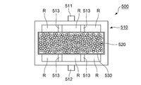
- FIG. 6 is a front view of a hollow fiber membrane module according to a conventional example.
- the hollow fiber membrane module 500 includes a cylindrical case 510 and a hollow fiber membrane bundle 520 housed in the case 510.
- this hollow fiber membrane module 500 an extra-membrane flow path passing through the outer wall surface of each hollow fiber membrane and an intra-membrane flow path passing through the hollow interior of each hollow fiber membrane are formed. Then, by using a hydrophilic material as the material of the hollow fiber membrane, the hollow fiber membrane module 500 can be used as a humidifier.
- the moisture on the wet air side is supplied to the dry air side by the membrane separation action of the hollow fiber membrane, and the dry air Can be humidified. Since the moisture is deprived on the humid air side, it can be used as a dehumidifier for drying the humid air.
- the ratio of the membrane area contributing to the membrane separation action to the membrane area of the entire hollow fiber membrane accommodated in the case 510 is determined. It is important to be able to make it bigger.
- the case 510 is provided with a supply port 511 and a discharge port 512 for the humid air at an upper portion and a lower portion of the case 510 in FIG. 6, respectively.
- a plurality of rectifying projections 513 for adjusting the flow of the fluid are provided on the inner wall surface of the case 510.
- the rectifying projections 513 project toward the outer peripheral surface of the hollow fiber membrane bundle 520 so as to secure a space (gap) R between the inner wall surface of the case 510 and the hollow fiber membrane bundle 520, and It is provided so as to extend from one end side to the other end side (in the drawing, from the near side to the back side of the drawing).
- the hollow fiber membrane bundle 520 is housed in the case 510 in a state where the hollow fiber membrane bundle 520 is inserted into the cylinder 530 made of a resin mesh.
- This cylinder 530 is manufactured by making the mesh into a cylindrical shape and heat-welding the ends. Therefore, not only is the production cost of the cylinder 530 high, but also the operation cost of inserting the hollow fiber membrane bundle 520 into the cylinder 530 is required.
- An object of the present invention is to provide a hollow fiber membrane module that can stabilize the posture of each hollow fiber membrane without inserting a hollow fiber membrane bundle into a cylinder.
- the present invention employs the following means in order to solve the above problems.
- the hollow fiber membrane module of the present invention is: A cylindrical case, A hollow fiber membrane bundle composed of a plurality of hollow fiber membranes housed in the case, At one end and the other end of the case, the openings at both ends of the case are sealed with the hollow interior of each hollow fiber membrane opened, and the hollow fiber membrane bundle is fixed to the case.
- a pair of sealing and fixing parts to be An extra-membrane flow path passing through the outer wall surface side of each hollow fiber membrane and an intra-membrane flow path passing through the hollow interior of each hollow fiber membrane are formed, and wet air is flowed through the extra-membrane flow path,
- the present invention between the inner wall surface of the case and the hollow fiber membrane bundle, there are provided a plurality of spaces serving as flow paths through which wet air flows from one end side of the case to the other end side. Therefore, it is possible to suppress the flow of the humid air from concentrating on any location.
- the restricting portion since the restricting portion is provided, it is restricted that the hollow fiber membrane enters the space, and the deformation of the hollow fiber membrane can be suppressed. Thereby, the posture of each hollow fiber membrane can be stabilized. Therefore, formation of a large gap between the hollow fiber membranes can be suppressed.
- the case has an extra-membrane flow path inlet provided at a position biased toward one end of the case, and a position biased toward the other end of the case, wherein the extra-membrane flow path inlet is provided through the hollow fiber membrane bundle.
- an extra-membrane flow path outlet provided on the opposite side, and
- the space is provided between the hollow fiber membrane bundle and a portion including the opening of the extramembrane flow channel inlet on the case inner wall surface, and the opening of the extramembrane flow channel outlet on the case inner wall surface. It is preferable that the space is also provided between the portion including the hollow fiber membrane bundle and the hollow fiber membrane bundle.
- the case includes a pair of plate portions facing each other, and a pair of side wall surface portions respectively connecting both sides of the pair of plate portions,
- the extramembrane flow channel inlet is provided on one of the pair of plate-like portions, and the extramembrane flow channel outlet is provided on the other,
- the space may be provided by the hollow fiber membrane bundle contacting the inner wall surfaces of the pair of side wall surface portions and not contacting the inner wall surfaces of the pair of plate-like portions.
- a space is provided between the plate-shaped portion provided with the extra-membrane flow channel inlet and the hollow fiber membrane bundle, and the space between the plate-shaped portion provided with the extra-membrane flow channel outlet and the hollow fiber membrane bundle is provided.
- a space is provided therebetween, and no space (gap) is formed between the hollow fiber membrane bundle and the pair of side wall surface portions. Therefore, when wet air flows from the space on the inlet side of the extra-membrane flow path to the space on the outlet side of the extra-membrane flow path, the wet air does not escape from between the hollow fiber membrane bundle and the pair of side wall surfaces, and the hollow air does not flow out. The moist air flows throughout the bundle.
- the inner wall surfaces of the pair of plate-shaped portions project toward the outer peripheral surface of the hollow fiber membrane bundle so as to secure the space, and extend from one end side to the other end side of the case, so that the fluid flows.
- a plurality of rectifying protrusions for adjusting the flow are provided.
- the restricting portion is a beam-shaped portion that connects between the rectifying protrusion and the side wall surface portion and between adjacent rectifying protrusions.
- the posture of each hollow fiber membrane can be stabilized without inserting the hollow fiber membrane bundle into the cylinder.
- FIG. 1 is a plan view of a hollow fiber membrane module according to an embodiment of the present invention.
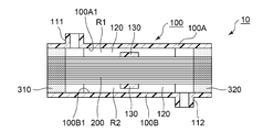
- FIG. 2 is a front view of the hollow fiber membrane module according to the embodiment of the present invention.
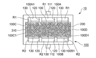
- FIG. 3 is a schematic sectional view of the hollow fiber membrane module according to the embodiment of the present invention.
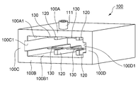
- FIG. 4 is a perspective view of a case according to the embodiment of the present invention.
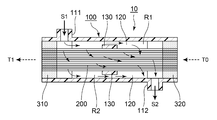
- FIG. 5 is a schematic cross-sectional view showing a main configuration of a humidifier using the hollow fiber membrane module according to the embodiment of the present invention.
- FIG. 6 is a front view of a hollow fiber membrane module according to a conventional example.
- the hollow fiber membrane module according to the present embodiment can be suitably used as, for example, a humidifier for humidifying an electrolyte membrane in a polymer electrolyte fuel cell. However, it can also be used as a dehumidifier.
- FIG. 1 is a plan view of a hollow fiber membrane module according to an embodiment of the present invention.
- FIG. 2 is a front view of the hollow fiber membrane module according to the embodiment of the present invention, and corresponds to a view of the hollow fiber membrane module viewed from the left side in FIG.
- FIG. 3 is a schematic cross-sectional view of the hollow fiber membrane module according to the embodiment of the present invention, and is a cross-sectional view along AA in FIG.
- FIG. 4 is a perspective view of a case provided in the hollow fiber membrane module according to the embodiment of the present invention.
- FIG. 5 is a schematic sectional view when the hollow fiber membrane module according to the embodiment of the present invention is used as a humidifier.
- the hollow fiber membrane module 10 includes a cylindrical case 100, a hollow fiber membrane bundle 200 including a plurality of hollow fiber membranes housed in the case 100, and a hollow fiber membrane bundle at one end and the other end of the case 100.
- a pair of sealing fixing portions 310 and 320 for fixing the fixing member 200 are provided.
- an extramembrane flow path (see solid arrows S1 and S2 in FIG. 5) that passes through the outer wall surface side of each hollow fiber membrane, and passes through the hollow interior of each hollow fiber membrane.
- An intra-membrane flow path is formed.
- the case 100 has a supply port 111 serving as an extra-membrane flow path inlet for supplying wet air to the extra-membrane flow path, an extra-membrane flow path outlet for discharging wet air (dried wet air). Outlet 112 is provided. Further, the hollow fiber membrane module 10 is supplied with dry air from the opening at the other end of the case 100 (on the side where the sealing and fixing portion 320 is provided), and the one end of the case 100 (at the sealing and fixing portion 310). It is used so that dry air (dry air after humidification) is discharged from the opening on the side (provided side).
- the hollow fiber membrane module 10 includes the case 100, the hollow fiber membrane bundle 200, and the pair of sealing fixing portions 310 and 320.
- the hollow fiber membrane bundle 200 has a configuration in which a plurality (about several hundred to several tens of thousands) of hollow fiber membranes are bundled.
- a hydrophilic material is used as a material for the hollow fiber membrane.
- Nafion which has a property of transmitting moisture by dissolution and diffusion
- PPSU polyphenyl sulfone
- the pair of sealing and fixing portions 310 and 320 seal the openings at both ends of the case 100 with the hollow interior of each hollow fiber membrane open at one end and the other end of the case 100, respectively.
- the thread membrane bundle 200 is fixed to the case 100.
- These sealing and fixing portions 310 and 320 are formed by curing a potting material such as an epoxy resin.
- the case 100 includes a pair of opposed plate-shaped portions 100A and 100B, and a pair of side wall surface portions 100C and 100D connecting both sides of the pair of plate-shaped portions 100A and 100B, respectively. Further, a supply port 111 serving as an extra-membrane flow channel inlet is provided in one plate-shaped portion 100A, and a discharge port 112 serving as an extra-membrane flow channel outlet is provided in the other plate-shaped portion 100B.
- the supply port 111 is provided at a position biased toward one end of the case 100, and the discharge port 112 is provided at a position biased toward the other end of the case 100, and is provided via the hollow fiber membrane bundle 200. And on the opposite side.
- rectifying projections 120 projecting toward the outer peripheral surface of the hollow fiber membrane bundle 200 are provided on the inner wall surfaces of the pair of plate portions 100A and 100B so as to secure the spaces R1 and R2.
- two rectifying projections 120 are provided on each of the plate-shaped portions 100A and 100B.
- the plurality of rectifying projections 120 extend from one end to the other end of the case 100 and play a role in regulating the flow of the fluid.
- the hollow fiber membrane bundle 200 comes into contact with the inner wall surfaces 100C1 and 100D1 of the pair of side wall surface portions 100C and 100D, and is provided with the above-described rectifying projections 120. It does not contact the inner wall surfaces 100A1 and 100B1. Thereby, the spaces R1 and R2 are provided. That is, the space R1 is provided between the portion including the opening of the supply port 111 (the inner wall surface 100A1 of the plate-shaped portion 100A) and the hollow fiber membrane bundle 200 on the inner wall surface of the case, and the inner wall surface of the case is exhausted. A space R2 is also provided between a portion including the opening of the outlet 112 (the inner wall surface 100B1 of the plate-shaped portion 100B) and the hollow fiber membrane bundle 200. As described above, between the inner wall surface of the case and the hollow fiber membrane bundle 200, a plurality of spaces R1 and R2 serving as flow paths through which wet air flows from one end side of the case 100 to the other end side are provided.
- the beam-shaped part 130 as a regulation part which regulates that a hollow fiber membrane enters into the space R1, R2 is provided partially, respectively.
- the beam-like portion 130 is provided so as to connect between the rectifying protrusion 120 and the side wall surface portions 100C and 100D, and between adjacent rectifying protrusions 120.
- the case 100 according to the present embodiment is a resin molded product. That is, the case 100 integrally including the pair of plate-like portions 100A and 100B, the pair of side wall surface portions 100C and 100D, the plurality of rectification protrusions 120, and the plurality of beam portions 130 is obtained by resin molding using a mold. Can be.
- the humidification (dehumidification) mechanism in the hollow fiber membrane module 10 according to the present embodiment will be described.
- the extra-membrane flow path passing through the outer wall surface side of each hollow fiber membrane in the hollow fiber membrane bundle 200 and the intramembrane flow passing through the hollow interior of each hollow fiber membrane. A road is formed.
- the extra-membrane flow path is a flow path that passes from the supply port 111 to the outer wall surface side of each hollow fiber membrane in the hollow fiber membrane bundle 200 and is discharged from the discharge port 112 (see solid line arrows S1 and S2 in FIG. 5). .
- the intra-membrane flow path is a flow path that passes through the hollow interior of each hollow fiber membrane in the hollow fiber membrane bundle 200 from the other end side of the case 100 and is discharged from one end side of the case 100 (dotted arrow in FIG. 5). T0, T1).
- the hollow fiber membrane module 10 is used so that wet air flows through the extra-membrane flow path and dry air flows through the intra-membrane flow path.
- the moisture on the humid air side is supplied to the dry air side by the membrane separation action of the hollow fiber membrane, and the dry air is humidified. Since the moisture is deprived on the wet air side, the wet air is dried. Therefore, it can be used as a humidifier or a dehumidifier.
- gaps are ensured between the plate-shaped portion 100A and the beam-shaped portion 130 and between the plate-shaped portion 100B and the beam-shaped portion 130, when the moist air flows through the spaces R1 and R2.
- each beam-shaped portion 130 does not hinder.
- ⁇ Excellent points of the hollow fiber membrane module according to the present example> According to the hollow fiber membrane module 10 according to the present embodiment, between the inner wall surface of the case 100 and the hollow fiber membrane bundle 200, a flow path through which wet air flows from one end side of the case 100 toward the other end side. A plurality of spaces R1 and R2 are provided. Therefore, it is possible to suppress the flow of the humid air from concentrating at any point, and to humid air into the hollow fiber membrane bundle 200 from the one end side of the case 100 to the other end side. Flow can be facilitated, and the ratio of the membrane area contributing to the membrane separation action can be increased.
- the hollow fiber membrane since the case 100 is provided with the beam-shaped part 130 as a regulating part, the hollow fiber membrane may enter the spaces R1 and R2. As a result, the deformation of the hollow fiber membrane can be suppressed. Thereby, the posture of each hollow fiber membrane can be stabilized. Therefore, formation of a large gap between the hollow fiber membranes can be suppressed. Therefore, it is possible to prevent the gap from being formed between the hollow fiber membranes from the space R1 toward the space R2. From this point as well, the ratio of the film area contributing to the membrane separation action can be increased.
- the space R1 is provided between a portion of the inner wall surface of the case including the opening of the supply port 111 (the inner wall surface 100A1 of the plate-shaped portion 100A) and the hollow fiber membrane bundle 200, and the space R2 is provided in the case.
- the hollow fiber membrane bundle 200 is provided between a portion of the inner wall surface including the opening of the outlet 112 (the inner wall surface 100B1 of the plate-shaped portion 100B) and the hollow fiber membrane bundle 200.
- no space is formed between the hollow fiber membrane bundle 200 and the pair of side wall surface portions 100C and 100D.
- the beam-shaped portion 130 may be provided at a plurality of positions between one end and the other end of the case 100.
- Reference Signs List 10 hollow fiber membrane module 50 first head 51 supply port 52 discharge port 60 second head 61 discharge port 62 supply port 100 case 100A, 100B plate portion 100A1, 100B1 inner wall surface 100C, 100D side wall surface portion 100C1, 100D1 inner wall surface 111 supply Mouth 112 Discharge port 120 Rectifying projection 130 Beam-shaped part 200 Hollow fiber membrane bundle 310, 320 Sealing fixing part R1, R2 Space
Landscapes
- Chemical & Material Sciences (AREA)
- Chemical Kinetics & Catalysis (AREA)
- Engineering & Computer Science (AREA)
- General Chemical & Material Sciences (AREA)
- Analytical Chemistry (AREA)
- Oil, Petroleum & Natural Gas (AREA)
- Manufacturing & Machinery (AREA)
- Sustainable Development (AREA)
- Life Sciences & Earth Sciences (AREA)
- Sustainable Energy (AREA)
- Electrochemistry (AREA)
- Combustion & Propulsion (AREA)
- Mechanical Engineering (AREA)
- General Engineering & Computer Science (AREA)
- Separation Using Semi-Permeable Membranes (AREA)
- Fuel Cell (AREA)
- Drying Of Gases (AREA)
Abstract
筒に中空糸膜束を挿入させなくても、各中空糸膜の姿勢を安定させることのできる中空糸膜モジュールを提供する。 筒状のケース100と、中空糸膜束200と、一対の封止固定部310,320と、を備え、各中空糸膜の外壁面側を通る膜外流路と、各中空糸膜の中空内部を通る膜内流路とが形成され、前記膜外流路に湿潤空気が流され、前記膜内流路に乾燥空気が流されることにより、各中空糸膜の膜分離作用により湿潤空気側の水分が乾燥空気側に供給される中空糸膜モジュール10であって、ケース内壁面と中空糸膜束200との間には、空間R1,R2が複数設けられると共に、各々の空間R1,R2と中空糸膜束200との間には、中空糸膜が空間R1,R2内に進入することを規制する規制部(梁状部130)がそれぞれ部分的に設けられていることを特徴とする。
Description
本発明は、加湿装置や除湿装置に用いることができる中空糸膜モジュールに関する。
例えば、固体高分子型の燃料電池においては、電解質膜を加湿させるために、中空糸膜モジュールを用いた加湿装置が設けられている。図6を参照して、従来例に係る中空糸膜モジュールについて説明する。図6は従来例に係る中空糸膜モジュールの正面図である。
従来例に係る中空糸膜モジュール500は、筒状のケース510と、ケース510内に収容される中空糸膜束520とを備えている。この中空糸膜モジュール500においては、各中空糸膜の外壁面側を通る膜外流路と、各中空糸膜の中空内部を通る膜内流路とが形成される。そして、中空糸膜の素材として、親水性の材料を用いることによって、中空糸膜モジュール500を加湿装置として利用することが可能となる。すなわち、膜外流路に湿潤空気が流れるようにし、膜内流路に乾燥空気が流れるようにすると、中空糸膜による膜分離作用によって、湿潤空気側の水分が乾燥空気側に供給され、乾燥空気を加湿させることが可能となる。なお、湿潤空気側は水分が奪われるため、湿潤空気を乾燥させるための除湿装置として利用することも可能である。
以上のような中空糸膜モジュール500において、加湿効率を高めるためには、ケース510内に収容される中空糸膜全体の膜面積に対して、膜分離作用に寄与する膜面積の割合を如何に大きくすることができるかが重要である。そして、ケース510には、図6中、ケース510の上部と下部に、それぞれ湿潤空気の供給口511と排出口512が設けられている。ケース510の内壁面全体に中空糸膜束520の外周面が密着していると、供給口511の付近と排出口512の付近に、流体の流れが集中してしまい易い。そこで、図示の従来例に係る中空糸膜モジュール500においては、ケース510の内壁面に、流体の流れを整える整流用突起513が複数設けられている。この整流用突起513は、ケース510の内壁面と中空糸膜束520との間に空間(隙間)Rを確保せしめるように中空糸膜束520の外周面に向かって突出すると共に、ケース510の一端側から他端側(図中、紙面の手前側から奥側)に向かって伸びるように設けられている。このような整流用突起513が設けられることによって、供給口511の付近と排出口512の付近に、流体の流れが集中してしまうことが抑制でき、膜分離作用に寄与する膜面積の割合を大きくすることが可能となっている。
しかしながら、上記の中空糸膜モジュール500のように、空間Rを設けた場合には、中空糸膜の一部が空間Rに進入するように変形することによって、中空糸膜同士の間に大きな隙間が形成される場合がある。これにより、湿潤空気が、大きな隙間を抜けて、供給口511から排出口512に流れてしまい、膜分離作用に寄与しない膜面積が増加してしまうことがある。そこで、従来、樹脂製のメッシュで作製された筒530に、中空糸膜束520を挿入させた状態で、中空糸膜束520をケース510に収容させていた。この筒530は、メッシュを筒状にして、端同士を熱溶着することに製作している。そのため、筒530の製作コストが高いだけでなく、筒530に中空糸膜束520を挿入させる作業コストも必要になっていた。
本発明の目的は、筒に中空糸膜束を挿入させなくても、各中空糸膜の姿勢を安定させることのできる中空糸膜モジュールを提供することにある。
本発明は、上記課題を解決するために以下の手段を採用した。
すなわち、本発明の中空糸膜モジュールは、
筒状のケースと、
前記ケース内に収容される複数の中空糸膜からなる中空糸膜束と、
前記ケースの一端側と他端側で、各中空糸膜の中空内部を開放させた状態で前記ケースの両端の開口部をそれぞれ封止し、かつ前記中空糸膜束を前記ケースに対して固定する一対の封止固定部と、
を備え、各中空糸膜の外壁面側を通る膜外流路と、各中空糸膜の中空内部を通る膜内流路とが形成され、前記膜外流路に湿潤空気が流され、前記膜内流路に乾燥空気が流されることにより、各中空糸膜の膜分離作用により湿潤空気側の水分が乾燥空気側に供給される中空糸膜モジュールであって、
前記ケース内壁面と前記中空糸膜束との間には、前記ケースの一端側から他端側に向かって湿潤空気が流れる流路となる空間が複数設けられると共に、
各々の前記空間と前記中空糸膜束との間には、前記中空糸膜が前記空間内に進入することを規制する規制部がそれぞれ部分的に設けられていることを特徴とする。
本発明によれば、ケース内壁面と中空糸膜束との間には、ケースの一端側から他端側に向かって湿潤空気が流れる流路となる空間が複数設けられている。そのため、湿潤空気の流れが、いずれかの箇所に集中してしまうことを抑制することができる。また、規制部が設けられているため、中空糸膜が空間内に進入してしまうことが規制され、中空糸膜が変形してしまうことを抑制することができる。これにより、各中空糸膜の姿勢を安定させることができる。従って、中空糸膜同士の間に大きな隙間が形成されてしまうことを抑制することができる。
前記ケースには、該ケースの一端側に偏った位置に設けられる膜外流路入口と、該ケースの他端側に偏った位置であって、前記中空糸膜束を介して前記膜外流路入口とは反対側に設けられる膜外流路出口とが設けられると共に、
前記ケース内壁面のうち前記膜外流路入口の開口部を含む部分と前記中空糸膜束との間に前記空間が設けられ、かつ、前記ケース内壁面のうち前記膜外流路出口の開口部を含む部分と前記中空糸膜束との間にも前記空間が設けられているとよい。
前記ケース内壁面のうち前記膜外流路入口の開口部を含む部分と前記中空糸膜束との間に前記空間が設けられ、かつ、前記ケース内壁面のうち前記膜外流路出口の開口部を含む部分と前記中空糸膜束との間にも前記空間が設けられているとよい。
これにより、膜外流路入口及び膜外流路出口の付近に湿潤空気の流れが集中してしまうことを抑制することができる。
前記ケースは、対向する一対の板状部と、これら一対の板状部の両側をそれぞれ繋ぐ一対の側壁面部と、を備え、
前記一対の板状部の一方に前記膜外流路入口が設けられ、他方に前記膜外流路出口が設けられると共に、
前記中空糸膜束は、前記一対の側壁面部の内壁面には接触し、前記一対の板状部の内壁面には接触しないことにより前記空間が設けられているよい。
前記一対の板状部の一方に前記膜外流路入口が設けられ、他方に前記膜外流路出口が設けられると共に、
前記中空糸膜束は、前記一対の側壁面部の内壁面には接触し、前記一対の板状部の内壁面には接触しないことにより前記空間が設けられているよい。
これにより、膜外流路入口が設けられている板状部と中空糸膜束との間には空間が設けられ、かつ膜外流路出口が設けられている板状部と中空糸膜束との間には空間が設けられると共に、中空糸膜束と一対の側壁面部との間には空間(隙間)は形成されない。従って、膜外流路入口側の空間から膜外流路出口側の空間に湿潤空気が流れる際においては、中空糸膜束と一対の側壁面部との間から湿潤空気が抜けてしまうことはなく、中空糸膜束全体に亘って湿潤空気が流れて行く。
前記一対の板状部の内壁面には、前記空間を確保せしめるように前記中空糸膜束の外周面に向かって突出すると共に、前記ケースの一端側から他端側に向かって伸び、流体の流れを整える複数の整流用突起がそれぞれ設けられているとよい。
また、前記規制部は、前記整流用突起と前記側壁面部との間、及び、隣り合う整流用突起間を繋ぐ梁状部であるとよい。
なお、上記各構成は、可能な限り組み合わせて採用し得る。
以上説明したように、本発明によれば、筒に中空糸膜束を挿入させなくても、各中空糸膜の姿勢を安定させることができる。
以下に図面を参照して、この発明を実施するための形態を、実施例に基づいて例示的に詳しく説明する。ただし、この実施例に記載されている構成部品の寸法、材質、形状、その相対配置などは、特に特定的な記載がない限りは、この発明の範囲をそれらのみに限定する趣旨のものではない。本実施例に係る中空糸膜モジュールは、例えば、固体高分子型の燃料電池において、電解質膜を加湿させるための加湿装置として好適に用いることができる。ただし、除湿装置としても利用することができる。
(実施例)
図1~図5を参照して、本発明の実施例に係る中空糸膜モジュールについて説明する。図1は本発明の実施例に係る中空糸膜モジュールの平面図である。図2は本発明の実施例に係る中空糸膜モジュールの正面図であり、図1中、中空糸膜モジュールを左側から見た図に相当する。図3は本発明の実施例に係る中空糸膜モジュールの模式的断面図であり、図1中のAA断面図である。図4は本発明の実施例に係る中空糸膜モジュールに備えられるケースの斜視図である。図5は本発明の実施例に係る中空糸膜モジュールを加湿装置として用いた場合の模式的断面図である。
図1~図5を参照して、本発明の実施例に係る中空糸膜モジュールについて説明する。図1は本発明の実施例に係る中空糸膜モジュールの平面図である。図2は本発明の実施例に係る中空糸膜モジュールの正面図であり、図1中、中空糸膜モジュールを左側から見た図に相当する。図3は本発明の実施例に係る中空糸膜モジュールの模式的断面図であり、図1中のAA断面図である。図4は本発明の実施例に係る中空糸膜モジュールに備えられるケースの斜視図である。図5は本発明の実施例に係る中空糸膜モジュールを加湿装置として用いた場合の模式的断面図である。
<加湿装置>
本実施例に係る中空糸膜モジュールを加湿装置として用いた場合について、特に、図5を参照して説明する。中空糸膜モジュール10は、筒状のケース100と、ケース100内に収容される複数の中空糸膜からなる中空糸膜束200と、ケース100の一端側と他端側で、中空糸膜束200を固定する一対の封止固定部310,320とを備えている。このように構成される中空糸膜モジュール10においては、各中空糸膜の外壁面側を通る膜外流路(図5中の実線矢印S1,S2参照)と、各中空糸膜の中空内部を通る膜内流路(図5中、点線矢印T0,T1参照)とが形成される。
本実施例に係る中空糸膜モジュールを加湿装置として用いた場合について、特に、図5を参照して説明する。中空糸膜モジュール10は、筒状のケース100と、ケース100内に収容される複数の中空糸膜からなる中空糸膜束200と、ケース100の一端側と他端側で、中空糸膜束200を固定する一対の封止固定部310,320とを備えている。このように構成される中空糸膜モジュール10においては、各中空糸膜の外壁面側を通る膜外流路(図5中の実線矢印S1,S2参照)と、各中空糸膜の中空内部を通る膜内流路(図5中、点線矢印T0,T1参照)とが形成される。
ケース100には、膜外流路に対して湿潤空気を供給するための膜外流路入口となる供給口111と、湿潤空気(乾燥された後の湿潤空気)を排出するための膜外流路出口となる排出口112が設けられている。また、中空糸膜モジュール10は、ケース100の他端側(封止固定部320が設けられている側)の開口部から乾燥空気が供給され、ケース100の一端側(封止固定部310が設けられている側)の開口部から乾燥空気(加湿された後の乾燥空気)が排出されるように用いられる。
<中空糸膜モジュール>
中空糸膜モジュール10について、より詳細に説明する。上記の通り、中空糸膜モジュール10は、ケース100と、中空糸膜束200と、一対の封止固定部310,320とを備えている。中空糸膜束200は、複数(数百本から数万本程度)の中空糸膜が束にされた構成である。中空糸膜の素材としては、親水性の素材が用いられる。例えば、溶解拡散により水分を透過する特性を有するナフィオンや、孔径制御による毛管凝縮機構により水分を透過する特性を有するPPSU(ポリフェニルスルホン)などを好適に用いることができる。これらの材料は、低溶出性であり、かつ強度も高いため、加湿装置や除湿装置に好適に用いることができる。一対の封止固定部310,320は、ケース100の一端側と他端側で、各中空糸膜の中空内部を開放させた状態でケース100の両端の開口部をそれぞれ封止し、かつ中空糸膜束200をケース100に対して固定している。これらの封止固定部310,320は、エポキシ樹脂などのポッティング材料が硬化することにより構成される。
中空糸膜モジュール10について、より詳細に説明する。上記の通り、中空糸膜モジュール10は、ケース100と、中空糸膜束200と、一対の封止固定部310,320とを備えている。中空糸膜束200は、複数(数百本から数万本程度)の中空糸膜が束にされた構成である。中空糸膜の素材としては、親水性の素材が用いられる。例えば、溶解拡散により水分を透過する特性を有するナフィオンや、孔径制御による毛管凝縮機構により水分を透過する特性を有するPPSU(ポリフェニルスルホン)などを好適に用いることができる。これらの材料は、低溶出性であり、かつ強度も高いため、加湿装置や除湿装置に好適に用いることができる。一対の封止固定部310,320は、ケース100の一端側と他端側で、各中空糸膜の中空内部を開放させた状態でケース100の両端の開口部をそれぞれ封止し、かつ中空糸膜束200をケース100に対して固定している。これらの封止固定部310,320は、エポキシ樹脂などのポッティング材料が硬化することにより構成される。
<ケース>
ケース100について、より詳細に説明する。ケース100は、対向する一対の板状部100A,100Bと、これら一対の板状部100A,100Bの両側をそれぞれ繋ぐ一対の側壁面部100C,100Dとを備えている。そして、一方の板状部100Aに膜外流路入口となる供給口111が設けられ、他方の板状部100Bに膜外流路出口となる排出口112が設けられている。供給口111は、ケース100の一端側に偏った位置に設けられており、排出口112は、ケース100の他端側に偏った位置であって、中空糸膜束200を介して供給口111とは反対側に設けられている。また、一対の板状部100A,100Bの内壁面には、空間R1,R2を確保せしめるように中空糸膜束200の外周面に向かって突出する整流用突起120がそれぞれ設けられている。なお、本実施例においては、各板状部100A,100Bに、それぞれ2か所の整流用突起120が設けられている。これら複数の整流用突起120は、ケース100の一端側から他端側に向かって伸び、流体の流れを整える役割を担っている。
ケース100について、より詳細に説明する。ケース100は、対向する一対の板状部100A,100Bと、これら一対の板状部100A,100Bの両側をそれぞれ繋ぐ一対の側壁面部100C,100Dとを備えている。そして、一方の板状部100Aに膜外流路入口となる供給口111が設けられ、他方の板状部100Bに膜外流路出口となる排出口112が設けられている。供給口111は、ケース100の一端側に偏った位置に設けられており、排出口112は、ケース100の他端側に偏った位置であって、中空糸膜束200を介して供給口111とは反対側に設けられている。また、一対の板状部100A,100Bの内壁面には、空間R1,R2を確保せしめるように中空糸膜束200の外周面に向かって突出する整流用突起120がそれぞれ設けられている。なお、本実施例においては、各板状部100A,100Bに、それぞれ2か所の整流用突起120が設けられている。これら複数の整流用突起120は、ケース100の一端側から他端側に向かって伸び、流体の流れを整える役割を担っている。
そして、中空糸膜束200は、一対の側壁面部100C,100Dの内壁面100C1,100D1には接触し、上記の整流用突起120が設けられていることにより、一対の板状部100A,100Bの内壁面100A1,100B1には接触しない。これにより、上記の空間R1,R2が設けられている。つまり、ケース内壁面のうち供給口111の開口部を含む部分(板状部100Aの内壁面100A1)と中空糸膜束200との間に空間R1が設けられ、かつ、ケース内壁面のうち排出口112の開口部を含む部分(板状部100Bの内壁面100B1)と中空糸膜束200との間にも空間R2が設けられている。このように、ケース内壁面と中空糸膜束200との間には、ケース100の一端側から他端側に向かって湿潤空気が流れる流路となる空間R1,R2が複数設けられている。
そして、各々の空間R1,R2と中空糸膜束200との間には、中空糸膜が空間R1,R2内に進入することを規制する規制部としての梁状部130がそれぞれ部分的に設けられている。より具体的には、梁状部130は、整流用突起120と側壁面部100C,100Dとの間、及び、隣り合う整流用突起120間を繋ぐように設けられている。なお、本実施例に係るケース100は、樹脂成形品である。すなわち、一対の板状部100A,100B、一対の側壁面部100C,100D、複数の整流用突起120及び複数の梁状部130を一体に備えるケース100を、金型を用いた樹脂成形によって得ることができる。
<加湿(除湿)メカニズム>
本実施例に係る中空糸膜モジュール10における加湿(除湿)メカニズムについて説明する。上記の通り、本実施例に係る中空糸膜モジュール10においては、中空糸膜束200における各中空糸膜の外壁面側を通る膜外流路と、各中空糸膜の中空内部を通る膜内流路とが形成されている。膜外流路は、供給口111から中空糸膜束200における各中空糸膜の外壁面側を通り、排出口112から排出されていく流路である(図5中の実線矢印S1,S2参照)。膜内流路は、ケース100の他端側から中空糸膜束200における各中空糸膜の中空内部を通り、ケース100の一端側から排出されていく流路である(図5中の点線矢印T0,T1参照)。
本実施例に係る中空糸膜モジュール10における加湿(除湿)メカニズムについて説明する。上記の通り、本実施例に係る中空糸膜モジュール10においては、中空糸膜束200における各中空糸膜の外壁面側を通る膜外流路と、各中空糸膜の中空内部を通る膜内流路とが形成されている。膜外流路は、供給口111から中空糸膜束200における各中空糸膜の外壁面側を通り、排出口112から排出されていく流路である(図5中の実線矢印S1,S2参照)。膜内流路は、ケース100の他端側から中空糸膜束200における各中空糸膜の中空内部を通り、ケース100の一端側から排出されていく流路である(図5中の点線矢印T0,T1参照)。
本実施例においては、膜外流路に湿潤空気が流れるようにし、膜内流路に乾燥空気が流れるように、中空糸膜モジュール10は用いられる。これにより、中空糸膜による膜分離作用によって、湿潤空気側の水分が乾燥空気側に供給され、乾燥空気は加湿される。湿潤空気側は水分が奪われるため、湿潤空気は乾燥される。従って、加湿装置または除湿装置として用いることが可能となる。なお、板状部100Aと梁状部130との間、及び板状部100Bと梁状部130との間には、それぞれ隙間が確保されているため、湿潤空気が空間R1,R2を流れる際に、各梁状部130が支障になることはない。
<本実施例に係る中空糸膜モジュールの優れた点>
本実施例に係る中空糸膜モジュール10によれば、ケース100の内壁面と中空糸膜束200との間には、ケース100の一端側から他端側に向かって湿潤空気が流れる流路となる空間R1,R2が複数設けられている。そのため、湿潤空気の流れが、いずれかの箇所に集中してしまうことを抑制することができ、ケース100の一端側から他端側の全域に亘って、中空糸膜束200内に湿潤空気を流れ易くすることでき、膜分離作用に寄与する膜面積の割合を大きくすることができる。そして、本実施例に係る中空糸膜モジュール10においては、ケース100に、規制部としての梁状部130が設けられているため、中空糸膜が空間R1,R2内に進入してしまうことが規制され、中空糸膜が変形してしまうことを抑制することができる。これにより、各中空糸膜の姿勢を安定させることができる。そのため、中空糸膜同士の間に大きな隙間が形成されてしまうことを抑制することができる。従って、空間R1から空間R2に向かって中空糸膜間に形成された隙間を抜けてしまうことを抑制することができる。この点からも、膜分離作用に寄与する膜面積の割合を大きくすることができる。
本実施例に係る中空糸膜モジュール10によれば、ケース100の内壁面と中空糸膜束200との間には、ケース100の一端側から他端側に向かって湿潤空気が流れる流路となる空間R1,R2が複数設けられている。そのため、湿潤空気の流れが、いずれかの箇所に集中してしまうことを抑制することができ、ケース100の一端側から他端側の全域に亘って、中空糸膜束200内に湿潤空気を流れ易くすることでき、膜分離作用に寄与する膜面積の割合を大きくすることができる。そして、本実施例に係る中空糸膜モジュール10においては、ケース100に、規制部としての梁状部130が設けられているため、中空糸膜が空間R1,R2内に進入してしまうことが規制され、中空糸膜が変形してしまうことを抑制することができる。これにより、各中空糸膜の姿勢を安定させることができる。そのため、中空糸膜同士の間に大きな隙間が形成されてしまうことを抑制することができる。従って、空間R1から空間R2に向かって中空糸膜間に形成された隙間を抜けてしまうことを抑制することができる。この点からも、膜分離作用に寄与する膜面積の割合を大きくすることができる。
また、空間R1は、ケース内壁面のうち供給口111の開口部を含む部分(板状部100Aの内壁面100A1)と中空糸膜束200との間に設けられ、かつ、空間R2は、ケース内壁面のうち排出口112の開口部を含む部分(板状部100Bの内壁面100B1)と中空糸膜束200との間に設けられている。これにより、供給口111及び排出口112の付近に湿潤空気の流れが集中してしまうことを抑制することができる。
更に、本実施例に係る中空糸膜モジュール10においては、中空糸膜束200と一対の側壁面部100C,100Dとの間には空間(隙間)は形成されない。これにより、供給口111側の空間R1から排出口112側の空間R2に湿潤空気が流れる際においては、中空糸膜束200と一対の側壁面部100C,100Dとの間から湿潤空気が抜けてしまうことはなく、中空糸膜束200全体に亘って湿潤空気が流れて行く。従って、膜分離作用に寄与する膜面積の割合を大きくすることができる。
(その他)
上記実施例においては、膜外流路を流れる湿潤空気と、膜内流路を流れる乾燥空気が逆方向となるように構成する場合を示した。しかしながら、膜外流路を流れる湿潤空気と、膜内流路を流れる乾燥空気が同方向となるようにすることもできる。例えば、膜内流路に対しては、点線の矢印とは反対方向に乾燥空気を流すようにすることもできる。ただし、加湿効率及び除湿効率を高めるためには、逆方向にするほうがよい。また、上記実施例においては、梁状部130は、ケース100における一端側と他端側の間の中央付近の一か所にのみ設ける場合を示した。しかしながら、梁状部130については、ケース100における一端側と他端側の間の複数個所に設けることもできる。
上記実施例においては、膜外流路を流れる湿潤空気と、膜内流路を流れる乾燥空気が逆方向となるように構成する場合を示した。しかしながら、膜外流路を流れる湿潤空気と、膜内流路を流れる乾燥空気が同方向となるようにすることもできる。例えば、膜内流路に対しては、点線の矢印とは反対方向に乾燥空気を流すようにすることもできる。ただし、加湿効率及び除湿効率を高めるためには、逆方向にするほうがよい。また、上記実施例においては、梁状部130は、ケース100における一端側と他端側の間の中央付近の一か所にのみ設ける場合を示した。しかしながら、梁状部130については、ケース100における一端側と他端側の間の複数個所に設けることもできる。
10 中空糸膜モジュール
50 第1ヘッド
51 供給口
52 排出口
60 第2ヘッド
61 排出口
62 供給口
100 ケース
100A,100B 板状部
100A1,100B1 内壁面
100C,100D 側壁面部
100C1,100D1 内壁面
111 供給口
112 排出口
120 整流用突起
130 梁状部
200 中空糸膜束
310,320 封止固定部
R1,R2 空間
50 第1ヘッド
51 供給口
52 排出口
60 第2ヘッド
61 排出口
62 供給口
100 ケース
100A,100B 板状部
100A1,100B1 内壁面
100C,100D 側壁面部
100C1,100D1 内壁面
111 供給口
112 排出口
120 整流用突起
130 梁状部
200 中空糸膜束
310,320 封止固定部
R1,R2 空間
Claims (5)
- 筒状のケースと、
前記ケース内に収容される複数の中空糸膜からなる中空糸膜束と、
前記ケースの一端側と他端側で、各中空糸膜の中空内部を開放させた状態で前記ケースの両端の開口部をそれぞれ封止し、かつ前記中空糸膜束を前記ケースに対して固定する一対の封止固定部と、
を備え、各中空糸膜の外壁面側を通る膜外流路と、各中空糸膜の中空内部を通る膜内流路とが形成され、前記膜外流路に湿潤空気が流され、前記膜内流路に乾燥空気が流されることにより、各中空糸膜の膜分離作用により湿潤空気側の水分が乾燥空気側に供給される中空糸膜モジュールであって、
前記ケース内壁面と前記中空糸膜束との間には、前記ケースの一端側から他端側に向かって湿潤空気が流れる流路となる空間が複数設けられると共に、
各々の前記空間と前記中空糸膜束との間には、前記中空糸膜が前記空間内に進入することを規制する規制部がそれぞれ部分的に設けられていることを特徴とする中空糸膜モジュール。 - 前記ケースには、該ケースの一端側に偏った位置に設けられる膜外流路入口と、該ケースの他端側に偏った位置であって、前記中空糸膜束を介して前記膜外流路入口とは反対側に設けられる膜外流路出口とが設けられると共に、
前記ケース内壁面のうち前記膜外流路入口の開口部を含む部分と前記中空糸膜束との間に前記空間が設けられ、かつ、前記ケース内壁面のうち前記膜外流路出口の開口部を含む部分と前記中空糸膜束との間にも前記空間が設けられていることを特徴とする請求項1に記載の中空糸膜モジュール。 - 前記ケースは、対向する一対の板状部と、これら一対の板状部の両側をそれぞれ繋ぐ一対の側壁面部と、を備え、
前記一対の板状部の一方に前記膜外流路入口が設けられ、他方に前記膜外流路出口が設けられると共に、
前記中空糸膜束は、前記一対の側壁面部の内壁面には接触し、前記一対の板状部の内壁面には接触しないことにより前記空間が設けられていることを特徴とする請求項2に記載の中空糸膜モジュール。 - 前記一対の板状部の内壁面には、前記空間を確保せしめるように前記中空糸膜束の外周面に向かって突出すると共に、前記ケースの一端側から他端側に向かって伸び、流体の流れを整える複数の整流用突起がそれぞれ設けられていることを特徴とする請求項1,2または3に記載の中空糸膜モジュール。
- 前記規制部は、前記整流用突起と前記側壁面部との間、及び、隣り合う整流用突起間を繋ぐ梁状部であることを特徴とする請求項4に記載の中空糸膜モジュール。
Priority Applications (4)
| Application Number | Priority Date | Filing Date | Title |
|---|---|---|---|
| US16/963,558 US11351504B2 (en) | 2018-07-30 | 2019-07-22 | Hollow fiber membrane module |
| EP19843737.8A EP3831464A4 (en) | 2018-07-30 | 2019-07-22 | Hollow fiber membrane module |
| JP2020533442A JP7026797B2 (ja) | 2018-07-30 | 2019-07-22 | 中空糸膜モジュール |
| CN201980009173.0A CN111683730B (zh) | 2018-07-30 | 2019-07-22 | 中空纤维膜组件 |
Applications Claiming Priority (2)
| Application Number | Priority Date | Filing Date | Title |
|---|---|---|---|
| JP2018-142504 | 2018-07-30 | ||
| JP2018142504 | 2018-07-30 |
Publications (1)
| Publication Number | Publication Date |
|---|---|
| WO2020026875A1 true WO2020026875A1 (ja) | 2020-02-06 |
Family
ID=69231764
Family Applications (1)
| Application Number | Title | Priority Date | Filing Date |
|---|---|---|---|
| PCT/JP2019/028703 WO2020026875A1 (ja) | 2018-07-30 | 2019-07-22 | 中空糸膜モジュール |
Country Status (5)
| Country | Link |
|---|---|
| US (1) | US11351504B2 (ja) |
| EP (1) | EP3831464A4 (ja) |
| JP (1) | JP7026797B2 (ja) |
| CN (1) | CN111683730B (ja) |
| WO (1) | WO2020026875A1 (ja) |
Cited By (1)
| Publication number | Priority date | Publication date | Assignee | Title |
|---|---|---|---|---|
| WO2022255086A1 (ja) * | 2021-06-02 | 2022-12-08 | Nok株式会社 | 中空糸膜モジュール |
Citations (5)
| Publication number | Priority date | Publication date | Assignee | Title |
|---|---|---|---|---|
| JPH0319535U (ja) * | 1989-07-06 | 1991-02-26 | ||
| JP2004202478A (ja) * | 2002-11-08 | 2004-07-22 | Nok Corp | 膜モジュール |
| JP2007283292A (ja) | 2006-03-24 | 2007-11-01 | Nok Corp | 中空糸膜モジュール |
| JP2011141083A (ja) * | 2010-01-07 | 2011-07-21 | Honda Motor Co Ltd | 加湿モジュール |
| JP2016035895A (ja) * | 2014-07-31 | 2016-03-17 | 現代自動車株式会社Hyundaimotor Company | 燃料電池用膜加湿器の中空糸膜密集度分配装置 |
Family Cites Families (10)
| Publication number | Priority date | Publication date | Assignee | Title |
|---|---|---|---|---|
| JPS5757555A (en) * | 1980-09-25 | 1982-04-06 | Terumo Corp | Hollow fiber type artificial lung |
| JP2003065566A (ja) * | 2001-08-24 | 2003-03-05 | Honda Motor Co Ltd | ガス加湿器およびガス加湿システム |
| JP4111086B2 (ja) * | 2003-07-17 | 2008-07-02 | Nok株式会社 | 中空糸膜モジュール及び燃料電池の加湿装置 |
| DE102004022021B4 (de) * | 2004-05-03 | 2007-05-16 | Daimler Chrysler Ag | Feuchtigkeitsaustauschmodul mit einem Bündel von für Feuchtigkeit durchlässigen Hohlfasermembranen |
| JP2006314919A (ja) | 2005-05-12 | 2006-11-24 | Nok Corp | 中空糸膜モジュール |
| JP5074743B2 (ja) * | 2006-11-13 | 2012-11-14 | トヨタ自動車株式会社 | 中空糸膜モジュール、燃料電池システム |
| US7871520B2 (en) * | 2007-12-18 | 2011-01-18 | Milton Roy Company | High-temperature membrane distillation |
| US20090242474A1 (en) * | 2008-04-01 | 2009-10-01 | Nok Corporation | Hollow fiber membrane module |
| JP2012130864A (ja) | 2010-12-22 | 2012-07-12 | Toray Ind Inc | 中空糸膜モジュール |
| CN110545902B (zh) * | 2017-04-11 | 2021-12-21 | Nok株式会社 | 中空纤维膜组件 |
-
2019
- 2019-07-22 US US16/963,558 patent/US11351504B2/en active Active
- 2019-07-22 WO PCT/JP2019/028703 patent/WO2020026875A1/ja unknown
- 2019-07-22 EP EP19843737.8A patent/EP3831464A4/en active Pending
- 2019-07-22 CN CN201980009173.0A patent/CN111683730B/zh active Active
- 2019-07-22 JP JP2020533442A patent/JP7026797B2/ja active Active
Patent Citations (5)
| Publication number | Priority date | Publication date | Assignee | Title |
|---|---|---|---|---|
| JPH0319535U (ja) * | 1989-07-06 | 1991-02-26 | ||
| JP2004202478A (ja) * | 2002-11-08 | 2004-07-22 | Nok Corp | 膜モジュール |
| JP2007283292A (ja) | 2006-03-24 | 2007-11-01 | Nok Corp | 中空糸膜モジュール |
| JP2011141083A (ja) * | 2010-01-07 | 2011-07-21 | Honda Motor Co Ltd | 加湿モジュール |
| JP2016035895A (ja) * | 2014-07-31 | 2016-03-17 | 現代自動車株式会社Hyundaimotor Company | 燃料電池用膜加湿器の中空糸膜密集度分配装置 |
Non-Patent Citations (1)
| Title |
|---|
| See also references of EP3831464A4 |
Cited By (1)
| Publication number | Priority date | Publication date | Assignee | Title |
|---|---|---|---|---|
| WO2022255086A1 (ja) * | 2021-06-02 | 2022-12-08 | Nok株式会社 | 中空糸膜モジュール |
Also Published As
| Publication number | Publication date |
|---|---|
| JPWO2020026875A1 (ja) | 2021-01-07 |
| CN111683730B (zh) | 2022-06-14 |
| CN111683730A (zh) | 2020-09-18 |
| EP3831464A1 (en) | 2021-06-09 |
| EP3831464A4 (en) | 2022-06-29 |
| US20200353416A1 (en) | 2020-11-12 |
| JP7026797B2 (ja) | 2022-02-28 |
| US11351504B2 (en) | 2022-06-07 |
Similar Documents
| Publication | Publication Date | Title |
|---|---|---|
| US20210075035A1 (en) | Humidifier, for Example for a Fuel Cell | |
| WO2020026875A1 (ja) | 中空糸膜モジュール | |
| JP6918097B2 (ja) | 中空糸膜モジュール | |
| JP5151853B2 (ja) | 加湿装置 | |
| WO2022255086A1 (ja) | 中空糸膜モジュール | |
| WO2022255047A1 (ja) | 中空糸膜モジュール | |
| WO2022255085A1 (ja) | 中空糸膜モジュール及び除加湿装置 | |
| WO2022255039A1 (ja) | 中空糸膜モジュール及び除加湿装置 | |
| WO2023058284A1 (ja) | 中空糸膜モジュール | |
| WO2022255046A1 (ja) | 中空糸膜モジュール | |
| US20240173675A1 (en) | Hollow fiber membrane module and dehumidification/humidification device | |
| WO2022255088A1 (ja) | 中空糸膜モジュール及び除加湿装置 | |
| JP2018199098A (ja) | 膜分離装置 | |
| WO2023276414A1 (ja) | 中空糸膜モジュール | |
| JP2019058896A (ja) | 中空糸膜モジュール | |
| JP2023545154A (ja) | 燃料電池加湿装置 | |
| CN117320798A (zh) | 加湿器 | |
| CN117836050A (zh) | 具有通道板的加湿装置、用于加湿装置的通道部分板和通道板 |
Legal Events
| Date | Code | Title | Description |
|---|---|---|---|
| 121 | Ep: the epo has been informed by wipo that ep was designated in this application |
Ref document number: 19843737 Country of ref document: EP Kind code of ref document: A1 |
|
| ENP | Entry into the national phase |
Ref document number: 2020533442 Country of ref document: JP Kind code of ref document: A |
|
| NENP | Non-entry into the national phase |
Ref country code: DE |
|
| ENP | Entry into the national phase |
Ref document number: 2019843737 Country of ref document: EP Effective date: 20210301 |