WO2020026537A1 - 送電設備監視システム、電線装着無線装置および送電設備監視方法 - Google Patents
送電設備監視システム、電線装着無線装置および送電設備監視方法 Download PDFInfo
- Publication number
- WO2020026537A1 WO2020026537A1 PCT/JP2019/016762 JP2019016762W WO2020026537A1 WO 2020026537 A1 WO2020026537 A1 WO 2020026537A1 JP 2019016762 W JP2019016762 W JP 2019016762W WO 2020026537 A1 WO2020026537 A1 WO 2020026537A1
- Authority
- WO
- WIPO (PCT)
- Prior art keywords
- wireless device
- tower
- data
- wire
- power transmission
- Prior art date
- Legal status (The legal status is an assumption and is not a legal conclusion. Google has not performed a legal analysis and makes no representation as to the accuracy of the status listed.)
- Ceased
Links
Images


Classifications
-
- H—ELECTRICITY
- H02—GENERATION; CONVERSION OR DISTRIBUTION OF ELECTRIC POWER
- H02G—INSTALLATION OF ELECTRIC CABLES OR LINES, OR OF COMBINED OPTICAL AND ELECTRIC CABLES OR LINES
- H02G1/00—Methods or apparatus specially adapted for installing, maintaining, repairing or dismantling electric cables or lines
- H02G1/02—Methods or apparatus specially adapted for installing, maintaining, repairing or dismantling electric cables or lines for overhead lines or cables
-
- H—ELECTRICITY
- H02—GENERATION; CONVERSION OR DISTRIBUTION OF ELECTRIC POWER
- H02J—ELECTRIC POWER NETWORKS; CIRCUIT ARRANGEMENTS OR SYSTEMS FOR SUPPLYING OR DISTRIBUTING ELECTRIC POWER; SYSTEMS FOR STORING ELECTRIC ENERGY
- H02J13/00—Circuit arrangements for providing remote monitoring or remote control of equipment in a power distribution network
-
- H—ELECTRICITY
- H02—GENERATION; CONVERSION OR DISTRIBUTION OF ELECTRIC POWER
- H02J—ELECTRIC POWER NETWORKS; CIRCUIT ARRANGEMENTS OR SYSTEMS FOR SUPPLYING OR DISTRIBUTING ELECTRIC POWER; SYSTEMS FOR STORING ELECTRIC ENERGY
- H02J50/00—Circuit arrangements or systems for wireless supply or distribution of electric power
- H02J50/10—Circuit arrangements or systems for wireless supply or distribution of electric power using inductive coupling
Definitions
- the present disclosure relates to a power transmission facility monitoring system, a wire-mounted radio device, and a power transmission facility monitoring method.
- Data related to the power transmission facility is obtained from a power transmission facility having a plurality of towers and a transmission and distribution line (hereinafter, abbreviated as “wire”) that is laid between the plurality of towers, and the data is wirelessly communicated.
- a power line maintenance and monitoring device power transmission equipment monitoring system
- a slave device wireless device
- a power transmission equipment monitoring system that transmits data obtained from power transmission equipment having a plurality of towers and electric wires that are wired between the plurality of towers while aggregating the data by multi-hop wireless communication, One or a plurality of tower-installed wireless devices installed in any of the plurality of towers and wirelessly transmitting and receiving the data, One or more wire-attached wireless devices attached to the wire, acquiring power by electromagnetic induction from a magnetic field generated around the wire by a current flowing through the wire, and wirelessly transmitting and receiving the data by the power, Has, At least one of the wire-attached wireless devices is arranged at a communicable distance from at least one of the tower-installed wireless devices, and a power transmission equipment monitoring system for transmitting the data with the tower-installed wireless devices is provided.
- a power transmission equipment monitoring system that transmits data obtained from power transmission equipment having a plurality of pylons and electric wires that are laid between the plurality of pylons while aggregating the data by multi-hop wireless communication, Installed in any of the plurality of towers, used with one or more tower installation wireless devices that wirelessly transmit and receive the data, Attached to the electric wire, configured to acquire power by electromagnetic induction from a magnetic field generated around the electric wire by a current flowing through the electric wire, and wirelessly transmit and receive the data by the electric power, There is provided an electric wire-attached wireless device that is arranged at a distance communicable from at least one of the tower installed wireless devices and transmits the data to the tower installed wireless device.
- a power transmission equipment monitoring method for transmitting data obtained from power transmission equipment having a plurality of pylons and electric wires that are laid between the plurality of pylons while aggregating the data by multi-hop wireless communication One or a plurality of tower installation wireless devices that transmit and receive the data wirelessly, and installed in any of the plurality of towers, and power is transmitted by electromagnetic induction from a magnetic field generated around the electric wire by a current flowing through the electric wire.
- FIG. 1 is a schematic configuration diagram illustrating a power transmission facility monitoring system according to an embodiment of the present disclosure.
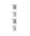
- FIG. 2 is a schematic configuration diagram illustrating an example of arrangement of wireless devices.
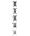
- FIG. 2 is a schematic configuration diagram illustrating an example of arrangement of wireless devices.
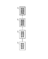
- FIG. 2 is a schematic configuration diagram illustrating an example of arrangement of wireless devices.
- 5 is a flowchart illustrating a power transmission facility monitoring method according to an embodiment of the present disclosure.
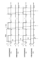
- FIG. 11 is a diagram illustrating operation timing of a wireless device according to a modification of one embodiment of the present disclosure.
- An object of the present disclosure is to provide a technology capable of constructing a power transmission facility monitoring system that performs stable multi-hop wireless communication in various environments in which a wireless device needs to be installed.
- a plurality of slave devices that acquire data on the power transmission equipment and transmit the data are provided.
- the wireless device is installed only on the tower.
- Patent Literature 1 since the wireless devices are installed only in the tower requiring monitoring, the interval between the wireless devices may be long. In such a case, stable wireless communication has been difficult.
- a wireless device has been installed in a tower only for relaying data transmission, even if it is not necessary to monitor a predetermined tower.
- predetermined power distribution equipment is used to connect to an external commercial power supply, or a solar power generation device and a battery are installed in order to obtain necessary power.
- the wireless devices installed on the steel tower have been increased in size.
- the equipment of the wireless device becomes unnecessarily large for a simple relay function, and the cost increases unnecessarily.
- the power transmission equipment monitoring system includes: A power transmission equipment monitoring system that transmits data obtained from power transmission equipment having a plurality of towers and electric wires that are wired between the plurality of towers while aggregating the data by multi-hop wireless communication, One or a plurality of tower-installed wireless devices installed in any of the plurality of towers and wirelessly transmitting and receiving the data, One or more wire-attached wireless devices attached to the wire, acquiring power by electromagnetic induction from a magnetic field generated around the wire by a current flowing through the wire, and wirelessly transmitting and receiving the data by the power, Has, At least one of the wire-mounted wireless devices is arranged at a communicable distance from at least one of the tower-mounted wireless devices, and transmits the data to and from the tower-mounted wireless device. According to this configuration, it is possible to construct a power transmission facility monitoring system that performs stable multi-hop wireless communication according to various environments that require installation of a wireless device.
- the relay wireless device is only the wire-mounted wireless device. According to this configuration, the relay wireless device can be configured at low cost, and the relay wireless device can be easily arranged.
- a plurality of the tower installation wireless devices are provided, At least one of the wire-mounted wireless devices is arranged at a distance communicable with at least one of the tower-installed wireless devices among the plurality of tower-installed wireless devices. According to this configuration, stable multi-hop wireless communication can be performed regardless of the interval between the tower installed wireless devices.
- the transmission distance of the power transmission equipment monitoring system can be interpolated by the amount of the pair of adjacent wire-mounted wireless devices without using a large-scale tower-installed wireless device.
- the power transmission equipment monitoring system according to any one of [1] to [5], A plurality of the tower installation wireless devices are provided, At least one of the wire-mounted wireless devices communicates from an outermost tower-installed wireless device in the inter-tower communication region outside a tower-to-tower communication region connecting the plurality of tower-installed wireless devices in a daisy chain. It is arranged at a possible distance. According to this configuration, the transmission distance of the entire power transmission equipment monitoring system can be lengthened by the amount of the wire-attached wireless device arranged outside the inter-tower communication area.
- Each of the tower-installed wireless device and the wire-mounted wireless device has a time synchronization function of synchronizing time with another wireless device that is either the tower-installed wireless device or the wire-mounted wireless device, At least the tower installed wireless device is based on a predetermined timing by the time synchronization function, a normal mode for transmitting the data with the other wireless device, and a sleep mode for pausing the transmission of the data after transmitting the data. , And the transition is made alternately. According to this configuration, it is possible to reduce power consumption of a tower-installed wireless device whose available power is limited.
- the wire-mounted wireless device is configured to execute only the normal mode without transiting to the sleep mode. According to this configuration, the configuration of the control unit in the wire-mounted wireless device can be simplified.
- a wire-mounted wireless device includes: A power transmission equipment monitoring system that transmits data obtained from power transmission equipment having a plurality of pylons and electric wires that are laid between the plurality of pylons while aggregating the data by multi-hop wireless communication, Installed in any of the plurality of towers, used with one or more tower installation wireless devices that wirelessly transmit and receive the data, Attached to the electric wire, configured to acquire power by electromagnetic induction from a magnetic field generated around the electric wire by a current flowing through the electric wire, and wirelessly transmit and receive the data by the electric power, It is located at a distance communicable from at least one of the tower installed wireless devices, and transmits the data to and from the tower installed wireless device. According to this configuration, it is possible to construct a power transmission facility monitoring system that performs stable multi-hop wireless communication according to various environments that require installation of a wireless device.
- a power transmission facility monitoring method includes: A power transmission equipment monitoring method for transmitting data obtained from power transmission equipment having a plurality of pylons and electric wires that are laid between the plurality of pylons while aggregating the data by multi-hop wireless communication, One or a plurality of tower installation wireless devices that transmit and receive the data wirelessly, and installed in any of the plurality of towers, and power is transmitted by electromagnetic induction from a magnetic field generated around the electric wire by a current flowing through the electric wire.
- FIG. 1 is a schematic configuration diagram illustrating a power transmission facility monitoring system according to the present embodiment.
- the power transmission equipment monitoring system 10 of the present embodiment is configured to transmit data obtained from the power transmission equipment 20 while aggregating the data by multi-hop wireless communication.
- multi-hop wireless communication refers to wireless communication in which data is sequentially transmitted using a plurality of wireless devices, and is referred to as “bucket relay wireless communication” or simply “relay wireless communication”. "Can be paraphrased.
- the “data” here means at least one of physical quantity data and image data that need to be monitored in managing the power transmission equipment 20.
- the power transmission equipment monitoring system 10 includes, for example, a plurality of wireless devices (nodes) 300 installed in the power transmission equipment 20 and a monitoring center (data aggregation device) 500.
- the power transmission facility 20 includes, for example, a plurality of towers 200, electric wires 100, and overhead ground wires 120.
- the plurality of steel towers 200 are provided at predetermined intervals, for example.
- the electric wire 100 is, for example, bridged between a plurality of towers 200.
- the electric wire 100 is configured as, for example, a so-called overhead transmission line.
- the electric wire 100 is, for example, a steel core aluminum stranded wire (ACSR).
- the overhead ground wire 120 is connected between the tops of the steel tower 200. Thereby, the electric wire 100 can be protected from lightning strike.
- the plurality of wireless devices 300 include, for example, one or a plurality of tower-installed wireless devices 320 and one or a plurality of wire-attached wireless devices 340. That is, in the power transmission equipment monitoring system 10 of the present embodiment, the tower installed radio device 320 and the electric wire mounted radio device 340 are provided in a mixed manner. This makes it possible to construct a power transmission facility monitoring system 10 that performs stable multi-hop wireless communication according to various environments where the wireless device 300 needs to be installed.
- Each of the plurality of wireless devices 300 is configured to be able to transmit information such as data with another wireless device 300 disposed at a communicable distance, for example.
- the “communicable distance” means a distance within which information can be transmitted.
- the “information such as data” here includes not only predetermined data but also a control signal described later.
- “transmitting information such as data” here includes transmitting information and receiving information. That is, in the multi-hop wireless communication, the direction in which data is transmitted (hereinafter, also referred to as “data transmission direction”) may be a predetermined one direction, but each of the plurality of wireless devices 300
- the present invention is not limited to the configuration for transmitting data, and may be configured to be capable of transmitting information such as data in both directions.
- each of the plurality of wireless devices 300 is, for example, one of the data acquisition wireless device (measurement wireless device) DD and the relay wireless device RD.
- the data acquisition wireless device DD has, for example, a data acquisition unit (not shown) that acquires data from the power transmission facility 20.
- the relay radio apparatus RD has, for example, no data acquisition unit, and is configured to only relay data transmission. Thereby, when the interval between the data acquisition wireless devices DD is long, the relay wireless device RD can be interposed between them.
- the term “interpose” means that the wireless device 300 is disposed between two wireless devices 300 in a data transmission path (hereinafter, also referred to as a “data transmission path”).
- Each of the plurality of wireless devices 300 has, for example, a time synchronization function of synchronizing the time with another wireless device 300. Thereby, the data acquisition timings of the plurality of data acquisition wireless devices DD can be aligned, and the data transmission timings of the plurality of wireless devices 300 can be aligned.
- the frequency band used for multi-hop wireless communication by the wireless device 300 of the present embodiment is, for example, a 920 MHz band. Note that the frequency band is an example, and another frequency band may be used.
- One or a plurality of tower installation wireless devices 320 are installed, for example, in any of the plurality of towers 200. Specifically, one or a plurality of tower installation wireless devices 320 are installed, for example, one for each tower in the plurality of towers 200. Note that, for example, a plurality of tower installation wireless devices 320 may be installed in one tower 200, or at least one tower 200 in which the tower installation wireless device 320 is not installed may exist.
- the tower installed wireless device 320 is configured to acquire power by a method other than electromagnetic induction, for example.
- the tower installed wireless device 320 is configured to wirelessly transmit and receive data from the power transmission facility 20 using, for example, power obtained from the outside.
- the tower installation wireless device 320 is connected to an external commercial power supply using, for example, predetermined power distribution equipment.
- the tower installed wireless device 320 includes, for example, a solar power generation device and a battery (storage battery), stores power generated by the solar power generation device in the battery, and acquires predetermined power from the battery. Have been.
- the tower-installed wireless device 320 As a disadvantage of the tower-installed wireless device 320, since the tower-installed wireless device 320 has the above-described facilities for obtaining power, the tower-installed wireless device 320 is compared with a wire-mounted wireless device 340 described below. It is large. On the other hand, as an advantage of the tower-installed wireless device 320, the power transmission facility 20 is not installed when the tower-installed wireless device 320 is installed because the electric wire 100 of the power transmission facility 20 is not involved in obtaining power. There is no need for a power outage.
- the tower-installed wireless device 320 is, for example, one of the data acquisition wireless device DD and the relay wireless device RD as described above.
- the tower installed wireless device 320 as the data acquisition wireless device DD includes, for example, a weather data acquisition unit 321, a lightning strike current measurement unit 322, a monitoring camera 323, a vibration sensor (not shown), and a sound level meter (not shown) as data acquisition units. ) And the like.
- the weather data acquisition unit 321 is configured to acquire, for example, at least one of temperature, humidity, wind direction, wind speed, and precipitation (snowfall).
- the lightning current measuring unit 322 is configured to measure a lightning current flowing when a lightning strike occurs on the overhead ground wire 120, for example.
- the monitoring camera 323 is configured to acquire, for example, image data (at least one of still image data and moving image data) of the power transmission facility 20 and its surroundings.
- the vibration sensor is configured to measure the vibration of the tower 200 or the inclination of the tower 200, for example, when wind is blown against the tower 200.
- the sound level meter is configured to measure, for example, wind noise generated from the electric wire 100 or the insulator when wind is blown to the power transmission equipment 20.
- the tower-installed wireless device 320 as the relay wireless device RD does not include the weather data acquisition unit 321 as the data acquisition unit, the lightning current measurement unit 322, the monitoring camera 323, the vibration sensor, the sound level meter, and the like. It is configured to perform only transmission relay.
- wire-attached wireless devices 340 are attached to the wire 100, for example.
- the wire-attached wireless device 340 is configured to acquire power by electromagnetic induction from a magnetic field generated around the wire 100 by a current flowing through the wire 100, for example.
- the wire-attached wireless device 340 is configured to wirelessly transmit and receive data using the power generated as described above, for example.
- the wire-mounted wireless device 340 has, for example, a current transformer unit (not shown).
- the current transformer unit has, for example, a core (not shown) and a coil (not shown).
- the core is provided in an annular shape so as to surround the outer periphery of the electric wire 100, for example.
- the core is made of, for example, a magnetic material.
- the coil is wound around at least a part of the core, for example.
- the wire-attached wireless device 340 is attached to the wire 100 as described above and acquires power by the current transformer unit. 320 is smaller.
- the electric wire mounting radio device 340 obtains electric power by the above-described current transformer unit, it is possible to always obtain a predetermined electric power while the electric wire 100 is energized.
- the wire-mounted wireless device 340 is, for example, one of the data acquisition wireless device DD and the relay wireless device RD as described above.
- the wire-attached wireless device 340 as the data acquisition wireless device DD includes, for example, a current measurement unit (not shown), a temperature sensor (not shown), a vibration sensor (not shown), and a GPS (Global Positioning System) as a data acquisition unit. (Not shown).
- a current measurement unit not shown
- a temperature sensor not shown
- a vibration sensor not shown
- a GPS Global Positioning System
- the current measurement unit has, for example, a measurement current transformer unit attached to the electric wire 100.
- the current transformer for measurement is configured, for example, in the same manner as the current transformer for acquiring electric power, and includes a measurement core (not shown) and a measurement coil (not shown). With such a configuration, an induced voltage can be generated in the measurement coil by electromagnetic induction based on a change in magnetic flux generated in the measurement core around the electric wire 100 by a current flowing through the electric wire 100. Thus, the current flowing through the electric wire 100 can be obtained by measuring the induced voltage generated in the measurement coil.
- the current transformer for measurement included in the current measuring unit may also serve as the current transformer for acquiring the above-described power.
- the temperature sensor is attached to the electric wire 100, for example, and is configured to measure the temperature of the electric wire 100.
- the temperature sensor has, for example, a thermocouple that outputs a voltage according to the temperature.
- the temperature sensor may include a thermistor whose resistance changes according to the temperature.
- the vibration sensor is configured to measure the vibration of the electric wire 100, for example, when wind is blown on the electric wire 100.
- the GPS measures the vibration of the electric wire 100, for example, when wind is blown on the electric wire 100, or measures the sag of the electric wire 100, such as when the electric wire 100 is slackened by snow or the like. It is configured as follows.
- the wire-attached wireless device 340 as the relay wireless device RD does not have a current measurement unit, a temperature sensor, a vibration sensor, a GPS, or the like as a data acquisition unit, and is configured to only relay data transmission. I have.
- the monitoring center 500 is connected, for example, by wire or wirelessly to the wireless device 300 at the last stage (the most downstream side) in the data transmission direction, receives the aggregated data, and monitors the data.
- the last wireless device 300 to which the monitoring center 500 is connected is, for example, a tower-installed wireless device 320.
- the monitoring center 500 is configured to be able to transmit a predetermined control signal to the wireless device 300.
- the control signal from the monitoring center 500 to each wireless device 300 is transmitted in a direction exactly opposite to the data transmission direction (data transmission path).
- the monitoring center 500 is connected to an electric power company (not shown) as a power supply source for supplying power to the electric wire 100 by wire or wirelessly, and transmits the aggregated data to the electric power company. Have been.
- the electric power company can control the power transmission capacity to the electric wire 100 based on the data from the power transmission equipment monitoring system 10.
- FIGS. 2A to 2C are schematic configuration diagrams each showing an example of the arrangement of wireless devices.
- the data transmission direction between the wireless devices 300 is not limited to this, and may be a direction opposite to the illustrated direction.
- At least one of the wire-mounted wireless devices 340 of the present embodiment is arranged, for example, at a communicable distance from at least one of the tower-installed wireless devices 320, and is configured to transmit data to and from the tower-installed wireless device 320. I have.
- the communicable distance of the wire-attached wireless device 340 is substantially equal to the communicable distance of the tower installed wireless device 320.
- At least one of the wire-attached wireless devices 340 of the present embodiment is arranged, for example, adjacent to at least one of the tower-installed wireless devices 320 at a communicable distance.
- adjacent (to adjacent) means that the wireless device 300 is not located between the wire-attached wireless device 340 and the tower-installed wireless device 320, and the tower is located closer to the tower than the other wireless devices 300. It means that it is located near the installed wireless device 320. Since at least one of the wire-mounted wireless devices 340 is adjacent to at least one of the tower installed wireless devices 320, the transmission distance per wireless device 300 can be reduced.
- the tower-installed wireless device 320 and the electric wire-attached wireless device 340 can be arranged, for example, as shown in FIGS. 2A to 2C.
- At least one of the wire-mounted wireless devices 340 is, for example, at a distance communicable with at least one of the tower-mounted wireless devices 320 among the plurality of tower-mounted wireless devices 320.
- At least one of the wire-mounted wireless devices 340 is, for example, interposed between the plurality of tower-installed wireless devices 320 at a distance communicable with at least one of the tower-installed wireless devices 320.
- the tower-installed wireless devices 320 and the electric wire-attached wireless devices 340 are alternately arranged within a communicable distance.
- the pair of wire-mounted wireless devices 340 is provided.
- the pair of wire-mounted wireless devices 340 are arranged, for example, at a distance at which they can communicate with each other, and are configured to transmit data without passing through the tower installed wireless device 320.
- the pair of wire-attached wireless devices 340 are arranged adjacent to each other, for example, at a communicable distance.
- the pair of wire-attached wireless devices 340 is not limited to being configured to transmit data in one predetermined direction, and is configured to be able to transmit information such as data in two directions. Is also good.
- At least one of the wire-mounted wireless devices 340 is, for example, outside the inter-tower communication area in which a plurality of tower-installed wireless devices 320 are connected in a daisy chain. It is arranged at a distance at which communication is possible from the outermost tower installation wireless device 320 in the communication area. Note that at least one of the wire-attached wireless devices 340 is arranged adjacent to, for example, the outermost tower-installed wireless device 320 at a communicable distance.
- a plurality of wireless devices 300 may be connected to one wireless device 300.
- each of the tower installation radio device 320 and the electric wire installation radio device 340 is one of the above-described data acquisition radio device DD or relay radio device RD according to the environment in the power transmission equipment monitoring system 10. Is selectively configured as
- the tower installation wireless device 320 as the data acquisition wireless device DD is installed, for example, on a predetermined tower 200 required to acquire at least one of physical quantity data and image data related to the tower 200.
- the tower installation wireless device 320 as the data acquisition wireless device DD is installed in a predetermined tower 200 in an environment where a large-scale data acquisition unit such as the weather data acquisition unit 321 is required.
- the electric wire attachment wireless device 340 as the data acquisition wireless device DD is attached to the electric wire 100 in an environment where it is required to acquire physical quantity data relating to the electric wire 100, for example.
- the device RD is interposed between the data acquisition wireless devices DD.
- which of the tower-installed wireless device 320 and the wire-mounted wireless device 340 is used as the relay wireless device RD is appropriately selected according to, for example, advantages and disadvantages of each wireless device 300.
- the relay wireless device RD when it is required to install a small or low-cost relay radio device RD, when it is required to obtain the power required for the relay radio device RD by self-generation, or when the radio condition of the relay radio device RD is good.
- the relay wireless device RD can be used as the electric wire mounted wireless device 340.
- the relay radio apparatus RD may be the tower installed radio apparatus 320.
- the relay radio apparatus RD when the power transmission facility 20 can be powered down, the relay radio apparatus RD can be configured at a low cost by using only the small wire-mounted radio apparatus 340 as the relay radio apparatus RD.
- the device RD can be easily arranged. Accordingly, it is possible to easily construct the power transmission equipment monitoring system 10 capable of performing stable transmission while suppressing an increase in the cost of the entire power transmission equipment monitoring system 10 due to the arrangement of the relay wireless devices RD.
- FIG. 3 is a flowchart illustrating a power transmission facility monitoring method according to the present embodiment. Note that steps are abbreviated as “S”.
- a plurality of wireless devices 300 are arranged in the power transmission facility 20.
- the tower installation wireless device 320 is installed on any of the towers 200.
- the wire mounting wireless device 340 is mounted on the wire 100.
- the type of wireless device 300 to be arranged is appropriately selected according to the environment in the power transmission equipment monitoring system 10 as described above.
- the monitoring center 500 is connected to one of the wireless devices 300 by wire or wirelessly.
- the timing of acquiring the first data is based on the information stored in the data acquisition wireless device DD.
- the timing of acquiring data after the second time may be based not only on the information stored in the data acquisition wireless device DD, but also on the control signal transmitted from the monitoring center 500.
- the data acquisition wireless device DD transmits data in the following procedure, for example. Specifically, first, when the upstream wireless device is provided upstream (upstream) of the data acquisition wireless device DD, data is received from the upstream wireless device. When data is received from the preceding wireless device, the data acquired by the data acquisition wireless device DD and the data received from the preceding wireless device are aggregated. After the data is aggregated, the aggregated data is transmitted to a downstream wireless device provided downstream (downstream) of the data acquisition wireless device DD.
- the data acquisition wireless device DD Only transmits the acquired data to the subsequent wireless device.
- the relay radio apparatus RD transmits data in the following procedure, for example. Specifically, first, data is received from the preceding-stage wireless device. When data is received from the upstream wireless device, the data received from the upstream wireless device is transmitted to the downstream wireless device. In other words, only the data transmission is relayed from the preceding wireless device to the succeeding wireless device.
- the last wireless device 300 transmits the aggregated data to the monitoring center 500 wirelessly or by wire, for example.
- the monitoring center 500 transmits the collected data wirelessly or by wire to, for example, an electric power company serving as a power supply source that supplies power to the electric wire 100.
- the electric power company controls the transmission capacity to the electric wire 100 based on the data.
- the data acquisition step S120 and the transmission step S130 are sequentially repeated at a predetermined cycle.
- the cycle of sequentially repeating the data acquisition step S120 and the transmission step S130 is, for example, three minutes.
- the electric power company that supplies power to the electric wire 100 can grasp the status of the power transmission equipment 20 in real time based on the data transmitted from the power transmission equipment monitoring system 10.
- the power transmission capacity to the electric wire 100 can be controlled based on the real-time data.
- efficient power transmission to the electric wire 100 can be realized.
- the above-described repetition cycle may be changed by a control signal transmitted from monitoring center 500.
- each wireless device 300 and the monitoring center 500 are stopped. Thereby, the power transmission equipment monitoring system 10 of the present embodiment is terminated.
- a tower installation wireless device 320 and a wire mounted wireless device 340 are provided in a mixed manner. At least one of the wire-mounted wireless devices 340 is arranged at a distance communicable with at least one of the tower-mounted wireless devices 320, and transmits data to and from the tower-mounted wireless device 320.
- the wire-attached wireless device 340 in combination with the tower-installed wireless device 320, the most appropriate wireless device 300 can be selectively used in the right place at the right place according to various environments where the wireless device 300 needs to be installed. Can be arranged. As a result, it is possible to construct a power transmission facility monitoring system 10 that performs stable multi-hop wireless communication according to various environments.
- Each of the tower installed wireless device 320 and the electric wire mounted wireless device 340 is one of the data acquisition wireless device DD and the relay wireless device RD.
- the relay wireless device RD can be interposed between the data acquisition wireless devices DD.
- stable multi-hop wireless communication can be performed regardless of the interval between the data acquisition wireless devices DD.
- the relay radio apparatus RD when it is possible to cause the power transmission facility 20 to lose power, the relay radio apparatus RD is configured to be only the small wire-mounted radio apparatus 340, so that the relay radio apparatus RD can be configured at low cost and the relay radio apparatus RD can be configured at low cost.
- the wireless device RD can be easily arranged. Accordingly, it is possible to easily construct the power transmission equipment monitoring system 10 capable of performing stable transmission while suppressing an increase in the cost of the entire power transmission equipment monitoring system 10 due to the arrangement of the relay wireless devices RD.
- At least one of the wire-mounted wireless devices 340 can be arranged at a distance communicable with at least one of the tower-installed wireless devices 320 among the plurality of tower-installed wireless devices 320. Accordingly, for example, when the interval between the tower-installed wireless devices 320 is long and wireless communication between the tower-installed wireless devices 320 is difficult, the large-sized tower-installed wireless device 320 is installed as the relay wireless device RD. Thus, a small electric wire mounting wireless device 340 capable of self-power generation can be arranged. As a result, stable multi-hop wireless communication can be performed regardless of the interval between the tower installed wireless devices 320.
- At least a pair of wire-attached wireless devices 340 may be arranged at a distance communicable with each other and configured to transmit data without passing through the tower installed wireless device 320. Accordingly, in an environment where the radio wave condition in the tower 200 is poor, or in an environment where a large amount of physical quantity of the electric wire 100 is required to be measured, a plurality of electric wire mounting wireless devices 340 can be continuously arranged.
- the power transmission equipment monitoring system can be used for the pair of wire-attached wireless devices 340 adjacent to each other.
- Ten transmission distances can be interpolated. As a result, the transmission distance of the entire power transmission equipment monitoring system 10 can be increased while reducing the power consumption of the power transmission equipment monitoring system 10.
- At least one of the wire-attached wireless devices 340 is located outside the inter-tower communication region where the plurality of tower-installed wireless devices 320 are connected in a daisy chain, and the outermost tower is installed in the inter-tower communication region. It can be located at a distance that allows communication from wireless device 320. For example, when the radio wave condition at the tower 200 is deteriorated outside the communication area between the towers, or when the physical quantity of the wire 100 is required to be measured outside the communication area between the towers, A wearable wireless device 340 can be located.
- the electric wire mounting apparatus disposed outside the inter-tower communication area can be used without using the large-sized tower installation wireless device 320.
- the transmission distance of the entire power transmission equipment monitoring system 10 can be increased by the amount of the wireless device 340.
- the following sleep mode may be applied in the processing of the wireless device 300.
- Each of the tower installed radio device 320 and the electric wire mounted radio device 340 has, for example, a time synchronization function of synchronizing the time with another radio device 300.
- At least one of the tower-installed wireless devices 320 is configured to alternately transition between the normal mode and the sleep mode based on a predetermined timing by the time synchronization function, for example.
- the “normal mode” here means, for example, a normal operation mode (operation mode) for transmitting data with another wireless device 300.
- the “sleep mode” here refers to a mode in which data transmission is suspended before transmitting data or after transmitting data. That is, in the “sleep mode”, power consumption can be suppressed.
- the wire-attached wireless device 340 is configured to execute only the normal mode, for example, without shifting to the sleep mode. That is, the wire-attached wireless device 340 always operates.
- FIG. 4 is a diagram illustrating operation timings of the wireless device according to the modification of the present embodiment.
- FIG. 4 shows a case where the data acquisition step S120 and the transmission step S130 are repeatedly performed in a predetermined cycle.
- FIG. 4 shows, as an example, a case where the tower-installed wireless devices 320 and the wire-attached wireless devices 340 are alternately arranged.
- the tower installed radio apparatus 320 is a data acquisition radio apparatus DD
- the electric wire mounted radio apparatus 340 is a relay radio apparatus RD.
- each wireless device 300 transmits a wake-up signal (wake-up data) indicating a time t3 at which the tower-installed wireless device 320 starts next time, together with the transmission of the data relating to the power transmission equipment 20.
- the monitoring center 500 may transmit a wake-up signal to each wireless device 300.
- the tower installation radio device 320a and the tower installation radio device 320c are switched from the normal mode to the sleep mode. (Time t2).
- the wire-attached wireless device 340 does not shift to the sleep mode, and always maintains the operating state.
- the tower installed radio apparatus 320 is activated (waked up) based on the wakeup signal described above.
- the above-described data acquisition step S120 and data transmission are sequentially performed.
- the tower installed wireless device 320 is shifted to the sleep mode until the next start time.
- the above processing is defined as one cycle, and the cycle is repeated.
- the wake-up signal is not transmitted in the last transmission step S130.
- the wire-attached wireless device 340b and the wire-attached wireless device 340d stop when they do not receive the wake-up signal.
- the wire-mounted wireless device 340 is always operated without shifting to the sleep mode, so that the control for making the wire-mounted wireless device 340 transition between the normal mode and the sleep mode is omitted. Can be.
- the configuration of the control unit of the wire-mounted wireless device 340 can be simplified.
- the tower installed wireless device 320 acquires power by an induced current flowing through the overhead ground wire 120 or directly or indirectly acquires power by electromagnetic induction from a magnetic field generated around the electric wire 100 by an electric current flowing through the electric wire 100. May be configured.
- the communicable distance of the wire-attached wireless device 340 is substantially equal to the communicable distance of the tower installed wireless device 320 has been described.
- the communicable distance of the tower installation wireless device 320 may be different.
- sufficient electric power required for communication can be secured. It may be longer than the distance.
- the tower installed wireless device 320 is the data acquisition wireless device DD has been described.
- at least one of the tower installed wireless device 320 is connected to the relay wireless device.
- the device RD may be used. Even when the tower installed wireless device 320 is the relay wireless device RD, the tower installed wireless device 320 is the same as the case where the tower installed wireless device 320 is the data acquisition wireless device DD except that data is not acquired.
- the device 320 can transition to the sleep mode after data transmission.
- the wire-attached wireless device 340 is configured by the relay wireless device RD has been described.
- the data acquisition wireless device DD may be used. Even when the wire-mounted radio device 340 is the data acquisition radio device DD, except that the data acquisition is performed before data transmission, similarly to the case where the wire-mounted radio device 340 is the relay radio device RD, The wire-attached wireless device 340 can be operated continuously without shifting to the sleep mode.
- each wireless device 300 transmits a wake-up signal in the transmission step S130 .
- the cycle ⁇ t at which the tower-installed wireless device 320 wakes up may be set in advance. Good. In this case, each wireless device 300 need not transmit the wake-up signal.
- At least the case where the tower-installed wireless device 320 is configured to transition to the sleep mode has been described. At least one of the devices 340 may be configured to transition to a sleep mode.
- a power transmission equipment monitoring system that transmits data obtained from power transmission equipment having a plurality of towers and electric wires that are wired between the plurality of towers while aggregating the data by multi-hop wireless communication, One or a plurality of tower-installed wireless devices installed in any of the plurality of towers and wirelessly transmitting and receiving the data, One or more wire-attached wireless devices attached to the wire, acquiring power by electromagnetic induction from a magnetic field generated around the wire by a current flowing through the wire, and wirelessly transmitting and receiving the data by the power, Has, A power transmission equipment monitoring system, wherein at least one of the wire-attached wireless devices is arranged at a communicable distance from at least one of the tower installed wireless devices, and transmits the data to the tower installed wireless device.
- the data acquisition wireless device When a previous-stage wireless device is provided at a stage preceding the data acquisition wireless device, a process of receiving the data from the preceding-stage wireless device, The data acquired by the data acquisition wireless device, and the data received from the preceding wireless device, a process of aggregating, A process of transmitting the aggregated data to a subsequent-stage wireless device provided at a later stage than the data acquisition wireless device; Do The relay wireless device, A process of receiving the data from the preceding-stage wireless device; A process of relaying the transmission of the data from the former-stage wireless device toward the latter-stage wireless device; The power transmission equipment monitoring system according to Supplementary Note 2 or 3, which performs the following.
- At least one of the wire-attached wireless devices may be any one of supplementary notes 1 to 4 arranged between the plurality of tower-installed wireless devices at a communicable distance from at least one of the tower-installed wireless devices.
- At least one pair of the wire-attached wireless devices is provided, The power transmission equipment monitoring system according to any one of Supplementary Notes 1 to 5, wherein the pair of wire-attached wireless devices are arranged at a distance communicable with each other, and transmit the data without passing through the tower installed wireless device.
- a plurality of the tower installation wireless devices are provided, At least one of the wire-mounted wireless devices communicates from an outermost tower-installed wireless device in the inter-tower communication region outside a tower-to-tower communication region connecting the plurality of tower-installed wireless devices in a daisy chain. 7.
- the power transmission equipment monitoring system according to any one of Supplementary Notes 1 to 6, arranged at a possible distance.
- Each of the tower-installed wireless device and the wire-mounted wireless device has a time synchronization function of synchronizing time with another wireless device that is either the tower-installed wireless device or the wire-mounted wireless device, At least the tower installed wireless device is based on a predetermined timing by the time synchronization function, a normal mode for transmitting the data with the other wireless device, and a sleep mode for pausing the transmission of the data after transmitting the data.
- the power transmission equipment monitoring system according to any one of Supplementary Notes 1 to 7, configured to alternately transition to:
- a power transmission equipment monitoring system that transmits data obtained from power transmission equipment having a plurality of pylons and electric wires that are laid between the plurality of pylons while aggregating the data by multi-hop wireless communication, Installed in any of the plurality of towers, used with one or more tower installation wireless devices that wirelessly transmit and receive the data, Attached to the electric wire, configured to acquire power by electromagnetic induction from a magnetic field generated around the electric wire by a current flowing through the electric wire, and wirelessly transmit and receive the data by the electric power, An electric wire-attached wireless device that is arranged at a distance communicable from at least one of the tower installed wireless devices and transmits the data to the tower installed wireless device.
- One or a plurality of tower installation wireless devices that transmit and receive the data wirelessly, and installed in any of the plurality of towers, and power is transmitted by electromagnetic induction from a magnetic field generated around the electric wire by a current flowing through the electric wire.
- Reference Signs List 10 power transmission equipment monitoring system 20 power transmission equipment 100 electric wire 120 overhead ground wire 200 pylon 300 radio equipment 320 (320a, 320c) pylon installation radio equipment 321 weather data acquisition part 322 lightning strike current measurement part 323 monitoring camera 340 (340b, 340d) Wireless device 500 Monitoring center DD Data acquisition wireless device RD Relay wireless device
Landscapes
- Engineering & Computer Science (AREA)
- Power Engineering (AREA)
- Computer Networks & Wireless Communication (AREA)
- Remote Monitoring And Control Of Power-Distribution Networks (AREA)
- Electric Cable Installation (AREA)
Abstract
複数の鉄塔と該複数の鉄塔の間に架線される電線とを有する送電設備から得られるデータをマルチホップ無線通信により集約しながら伝送する送電設備監視システムであって、複数の鉄塔のいずれかに設置され、データを無線で送受信する1つ又は複数の鉄塔設置無線装置と、電線に装着され、電線に流れる電流によって該電線の周囲に生じる磁界からの電磁誘導により電力を取得し、当該電力によってデータを無線で送受信する1つ又は複数の電線装着無線装置と、を有し、電線装着無線装置の少なくとも1つは、鉄塔設置無線装置の少なくとも1つから通信可能な距離で配置され、該鉄塔設置無線装置とデータを伝送する。
Description
本開示は、送電設備監視システム、電線装着無線装置および送電設備監視方法に関する。
本出願は、2018年7月30日出願の日本国出願「特願2018-142011」に基づく優先権を主張し、前記日本出願に記載された全ての記載内容を援用するものである。
本出願は、2018年7月30日出願の日本国出願「特願2018-142011」に基づく優先権を主張し、前記日本出願に記載された全ての記載内容を援用するものである。
複数の鉄塔と、該複数の鉄塔の間に架線される送配電線(以下、「電線」と略す)と、を有する送電設備から、該送電設備に係るデータを取得し、該データを無線通信により伝送する子機装置(無線装置)を有する送電線保守監視装置(送電設備監視システム)が開示されている(例えば、特許文献1)。
本開示の一態様によれば、
複数の鉄塔と該複数の鉄塔の間に架線される電線とを有する送電設備から得られるデータをマルチホップ無線通信により集約しながら伝送する送電設備監視システムであって、
前記複数の鉄塔のいずれかに設置され、前記データを無線で送受信する1つ又は複数の鉄塔設置無線装置と、
前記電線に装着され、前記電線に流れる電流によって該電線の周囲に生じる磁界からの電磁誘導により電力を取得し、当該電力によって前記データを無線で送受信する1つ又は複数の電線装着無線装置と、
を有し、
前記電線装着無線装置の少なくとも1つは、前記鉄塔設置無線装置の少なくとも1つから通信可能な距離で配置され、該鉄塔設置無線装置と前記データを伝送する
送電設備監視システムが提供される。
複数の鉄塔と該複数の鉄塔の間に架線される電線とを有する送電設備から得られるデータをマルチホップ無線通信により集約しながら伝送する送電設備監視システムであって、
前記複数の鉄塔のいずれかに設置され、前記データを無線で送受信する1つ又は複数の鉄塔設置無線装置と、
前記電線に装着され、前記電線に流れる電流によって該電線の周囲に生じる磁界からの電磁誘導により電力を取得し、当該電力によって前記データを無線で送受信する1つ又は複数の電線装着無線装置と、
を有し、
前記電線装着無線装置の少なくとも1つは、前記鉄塔設置無線装置の少なくとも1つから通信可能な距離で配置され、該鉄塔設置無線装置と前記データを伝送する
送電設備監視システムが提供される。
本開示の他の態様によれば、
複数の鉄塔と該複数の鉄塔の間に架線される電線とを有する送電設備から得られるデータをマルチホップ無線通信により集約しながら伝送する送電設備監視システムに設けられ、
前記複数の鉄塔のいずれかに設置され、前記データを無線で送受信する1つ又は複数の鉄塔設置無線装置とともに用いられ、
前記電線に装着され、前記電線に流れる電流によって該電線の周囲に生じる磁界からの電磁誘導により電力を取得し、当該電力によって前記データを無線で送受信するよう構成され、
前記鉄塔設置無線装置の少なくとも1つから通信可能な距離で配置され、該鉄塔設置無線装置と前記データを伝送する
電線装着無線装置が提供される。
複数の鉄塔と該複数の鉄塔の間に架線される電線とを有する送電設備から得られるデータをマルチホップ無線通信により集約しながら伝送する送電設備監視システムに設けられ、
前記複数の鉄塔のいずれかに設置され、前記データを無線で送受信する1つ又は複数の鉄塔設置無線装置とともに用いられ、
前記電線に装着され、前記電線に流れる電流によって該電線の周囲に生じる磁界からの電磁誘導により電力を取得し、当該電力によって前記データを無線で送受信するよう構成され、
前記鉄塔設置無線装置の少なくとも1つから通信可能な距離で配置され、該鉄塔設置無線装置と前記データを伝送する
電線装着無線装置が提供される。
本開示の更に他の態様によれば、
複数の鉄塔と該複数の鉄塔間に架線される電線とを有する送電設備から得られるデータをマルチホップ無線通信により集約しながら伝送する送電設備監視方法であって、
前記データを無線で送受信する1つ又は複数の鉄塔設置無線装置を、前記複数の鉄塔のいずれかに設置することと、前記電線に流れる電流によって該電線の周囲に生じる磁界から電磁誘導により電力を取得し、当該電力によって前記データを無線で送受信する1つ又は複数の電線装着無線装置を、前記電線に装着することと、を行う配置工程と、
前記鉄塔設置無線装置および前記電線装着無線装置のうち少なくともいずれかにより、前記送電設備から前記データを取得するデータ取得工程と、
前記鉄塔設置無線装置と前記電線装着無線装置とを用いて、マルチホップ無線通信により前記データを伝送する伝送工程と、
を有し、
前記配置工程では、
前記電線装着無線装置の少なくとも1つを、前記鉄塔設置無線装置の少なくとも1つから通信可能な距離で配置し、
前記伝送工程では、
前記電線装着無線装置と前記鉄塔設置無線装置との間で前記データを伝送する
送電設備監視方法が提供される。
複数の鉄塔と該複数の鉄塔間に架線される電線とを有する送電設備から得られるデータをマルチホップ無線通信により集約しながら伝送する送電設備監視方法であって、
前記データを無線で送受信する1つ又は複数の鉄塔設置無線装置を、前記複数の鉄塔のいずれかに設置することと、前記電線に流れる電流によって該電線の周囲に生じる磁界から電磁誘導により電力を取得し、当該電力によって前記データを無線で送受信する1つ又は複数の電線装着無線装置を、前記電線に装着することと、を行う配置工程と、
前記鉄塔設置無線装置および前記電線装着無線装置のうち少なくともいずれかにより、前記送電設備から前記データを取得するデータ取得工程と、
前記鉄塔設置無線装置と前記電線装着無線装置とを用いて、マルチホップ無線通信により前記データを伝送する伝送工程と、
を有し、
前記配置工程では、
前記電線装着無線装置の少なくとも1つを、前記鉄塔設置無線装置の少なくとも1つから通信可能な距離で配置し、
前記伝送工程では、
前記電線装着無線装置と前記鉄塔設置無線装置との間で前記データを伝送する
送電設備監視方法が提供される。
[本開示が解決しようとする課題]
本開示の目的は、無線装置の設置が必要となる様々な環境に応じて、安定的なマルチホップ無線通信を行う送電設備監視システムを構築することができる技術を提供することである。
本開示の目的は、無線装置の設置が必要となる様々な環境に応じて、安定的なマルチホップ無線通信を行う送電設備監視システムを構築することができる技術を提供することである。
[本開示の効果]
本開示によれば、無線装置の設置が必要となる様々な環境に応じて、安定的なマルチホップ無線通信を行う送電設備監視システムを構築することができる。
本開示によれば、無線装置の設置が必要となる様々な環境に応じて、安定的なマルチホップ無線通信を行う送電設備監視システムを構築することができる。
[本開示の実施形態の説明]
<発明者等の得た知見>
まず、発明者等の得た知見について説明する。
<発明者等の得た知見>
まず、発明者等の得た知見について説明する。
特許文献1の送電設備監視システムでは、送電設備に係るデータを取得するとともに当該データを伝送する複数の子機装置(以下、無線装置)が設けられていた。特許文献1の構成では、無線装置は鉄塔のみに設置されていた。
しかしながら、特許文献1の構成では、監視が必要な鉄塔だけに無線装置を設置していたため、無線装置間の間隔が長くなることがあった。このような場合、安定的な無線通信が困難となっていた。
そこで、従来では、所定の鉄塔を監視する必要がなくても、データの伝送を中継するためだけに、鉄塔に無線装置を設置していた。ここで、鉄塔に設置される無線装置では、必要な電力を得るために、例えば、所定の配電設備を用いて外部の商用電源に接続したり、太陽光発電装置およびバッテリを設置したりしていた。このような設備が必要となることから、鉄塔に設置される無線装置は、大型化していた。このため、上述のように、所定の鉄塔に対して中継用の無線装置を設置する場合では、当該無線装置の設備が、単なる中継機能に対して必要以上に大掛かりとなり、コストが必要以上に増加していた。その結果、小型または低コストな無線装置の設置が求められる環境などでは、安定的なマルチホップ無線通信を行う送電設備監視システムの構築が困難となっていた。
したがって、無線装置の設置が必要となる様々な環境に応じて、安定的なマルチホップ無線通信を行う送電設備監視システムを構築することができる技術が望まれていた。
本開示は、発明者等が見出した上記知見に基づくものである。
<本開示の実施態様>
次に、本開示の実施態様を列記して説明する。
次に、本開示の実施態様を列記して説明する。
[1]本開示の一態様に係る送電設備監視システムは、
複数の鉄塔と該複数の鉄塔の間に架線される電線とを有する送電設備から得られるデータをマルチホップ無線通信により集約しながら伝送する送電設備監視システムであって、
前記複数の鉄塔のいずれかに設置され、前記データを無線で送受信する1つ又は複数の鉄塔設置無線装置と、
前記電線に装着され、前記電線に流れる電流によって該電線の周囲に生じる磁界からの電磁誘導により電力を取得し、当該電力によって前記データを無線で送受信する1つ又は複数の電線装着無線装置と、
を有し、
前記電線装着無線装置の少なくとも1つは、前記鉄塔設置無線装置の少なくとも1つから通信可能な距離で配置され、該鉄塔設置無線装置と前記データを伝送する。
この構成によれば、無線装置の設置が必要となる様々な環境に応じて、安定的なマルチホップ無線通信を行う送電設備監視システムを構築することができる。
複数の鉄塔と該複数の鉄塔の間に架線される電線とを有する送電設備から得られるデータをマルチホップ無線通信により集約しながら伝送する送電設備監視システムであって、
前記複数の鉄塔のいずれかに設置され、前記データを無線で送受信する1つ又は複数の鉄塔設置無線装置と、
前記電線に装着され、前記電線に流れる電流によって該電線の周囲に生じる磁界からの電磁誘導により電力を取得し、当該電力によって前記データを無線で送受信する1つ又は複数の電線装着無線装置と、
を有し、
前記電線装着無線装置の少なくとも1つは、前記鉄塔設置無線装置の少なくとも1つから通信可能な距離で配置され、該鉄塔設置無線装置と前記データを伝送する。
この構成によれば、無線装置の設置が必要となる様々な環境に応じて、安定的なマルチホップ無線通信を行う送電設備監視システムを構築することができる。
[2]上記[1]に記載の送電設備監視システムにおいて、
前記鉄塔設置無線装置および前記電線装着無線装置のそれぞれは、
前記送電設備から前記データを取得するデータ取得部を有するデータ取得無線装置、
または、前記データ取得部を有さず、前記データの伝送の中継のみを行う中継無線装置、
のうちいずれかである。
この構成によれば、データ取得無線装置間の間隔に関わらず、安定的なマルチホップ無線通信を行うことができる。
前記鉄塔設置無線装置および前記電線装着無線装置のそれぞれは、
前記送電設備から前記データを取得するデータ取得部を有するデータ取得無線装置、
または、前記データ取得部を有さず、前記データの伝送の中継のみを行う中継無線装置、
のうちいずれかである。
この構成によれば、データ取得無線装置間の間隔に関わらず、安定的なマルチホップ無線通信を行うことができる。
[3]上記[2]に記載の送電設備監視システムにおいて、
前記中継無線装置は、前記電線装着無線装置のみである。
この構成によれば、中継無線装置を低コストに構成するとともに、中継無線装置を容易に配置することができる。
前記中継無線装置は、前記電線装着無線装置のみである。
この構成によれば、中継無線装置を低コストに構成するとともに、中継無線装置を容易に配置することができる。
[4]上記[1]~[3]のいずれか1つに記載の送電設備監視システムにおいて、
前記鉄塔設置無線装置は、複数設けられ、
前記電線装着無線装置の少なくとも1つは、前記複数の鉄塔設置無線装置の間で前記鉄塔設置無線装置の少なくとも1つから通信可能な距離に配置される。
この構成によれば、鉄塔設置無線装置間の間隔に関わらず、安定的なマルチホップ無線通信を行うことができる。
前記鉄塔設置無線装置は、複数設けられ、
前記電線装着無線装置の少なくとも1つは、前記複数の鉄塔設置無線装置の間で前記鉄塔設置無線装置の少なくとも1つから通信可能な距離に配置される。
この構成によれば、鉄塔設置無線装置間の間隔に関わらず、安定的なマルチホップ無線通信を行うことができる。
[5]上記[1]~[4]のいずれか1つに記載の送電設備監視システムにおいて、
前記電線装着無線装置は、少なくとも一対設けられ、
前記一対の電線装着無線装置は、互いに通信可能な距離で配置され、前記鉄塔設置無線装置を介さずに前記データを伝送する。
この構成によれば、大掛かりな鉄塔設置無線装置を用いずに、隣り合う一対の電線装着無線装置の分だけ、送電設備監視システムの伝送距離を補間することができる。
前記電線装着無線装置は、少なくとも一対設けられ、
前記一対の電線装着無線装置は、互いに通信可能な距離で配置され、前記鉄塔設置無線装置を介さずに前記データを伝送する。
この構成によれば、大掛かりな鉄塔設置無線装置を用いずに、隣り合う一対の電線装着無線装置の分だけ、送電設備監視システムの伝送距離を補間することができる。
[6]上記[1]~[5]のいずれか1つに記載の送電設備監視システムにおいて、
前記鉄塔設置無線装置は、複数設けられ、
前記電線装着無線装置の少なくとも1つは、前記複数の鉄塔設置無線装置同士を数珠つなぎに結んだ鉄塔間通信領域よりも外側に、前記鉄塔間通信領域のうち最も外側の鉄塔設置無線装置から通信可能な距離で配置される。
この構成によれば、鉄塔間通信領域よりも外側に配置された電線装着無線装置の分だけ、送電設備監視システム全体としての伝送距離を長くことができる。
前記鉄塔設置無線装置は、複数設けられ、
前記電線装着無線装置の少なくとも1つは、前記複数の鉄塔設置無線装置同士を数珠つなぎに結んだ鉄塔間通信領域よりも外側に、前記鉄塔間通信領域のうち最も外側の鉄塔設置無線装置から通信可能な距離で配置される。
この構成によれば、鉄塔間通信領域よりも外側に配置された電線装着無線装置の分だけ、送電設備監視システム全体としての伝送距離を長くことができる。
[7]上記[1]~[6]のいずれか1つに記載の送電設備監視システムにおいて、
前記鉄塔設置無線装置および前記電線装着無線装置のそれぞれは、前記鉄塔設置無線装置または前記電線装着無線装置のうちいずれかである他の無線装置と時刻を同期する時刻同期機能を有し、
少なくとも前記鉄塔設置無線装置は、前記時刻同期機能による所定のタイミングに基づいて、前記他の無線装置と前記データを伝送する通常モードと、前記データを伝送した後に前記データの伝送を休止するスリープモードと、に交互に遷移するよう構成される。
この構成によれば、使用可能な電力が有限である鉄塔設置無線装置を省電力化することができる。
前記鉄塔設置無線装置および前記電線装着無線装置のそれぞれは、前記鉄塔設置無線装置または前記電線装着無線装置のうちいずれかである他の無線装置と時刻を同期する時刻同期機能を有し、
少なくとも前記鉄塔設置無線装置は、前記時刻同期機能による所定のタイミングに基づいて、前記他の無線装置と前記データを伝送する通常モードと、前記データを伝送した後に前記データの伝送を休止するスリープモードと、に交互に遷移するよう構成される。
この構成によれば、使用可能な電力が有限である鉄塔設置無線装置を省電力化することができる。
[8]上記[7]に記載の送電設備監視システムにおいて、
前記電線装着無線装置は、前記スリープモードに遷移せずに、前記通常モードのみを実行するよう構成される。
この構成によれば、電線装着無線装置のうちの制御部の構成を簡略化することができる。
前記電線装着無線装置は、前記スリープモードに遷移せずに、前記通常モードのみを実行するよう構成される。
この構成によれば、電線装着無線装置のうちの制御部の構成を簡略化することができる。
[9]本開示の他の態様に係る電線装着無線装置は、
複数の鉄塔と該複数の鉄塔の間に架線される電線とを有する送電設備から得られるデータをマルチホップ無線通信により集約しながら伝送する送電設備監視システムに設けられ、
前記複数の鉄塔のいずれかに設置され、前記データを無線で送受信する1つ又は複数の鉄塔設置無線装置とともに用いられ、
前記電線に装着され、前記電線に流れる電流によって該電線の周囲に生じる磁界からの電磁誘導により電力を取得し、当該電力によって前記データを無線で送受信するよう構成され、
前記鉄塔設置無線装置の少なくとも1つから通信可能な距離で配置され、該鉄塔設置無線装置と前記データを伝送する。
この構成によれば、無線装置の設置が必要となる様々な環境に応じて、安定的なマルチホップ無線通信を行う送電設備監視システムを構築することができる。
複数の鉄塔と該複数の鉄塔の間に架線される電線とを有する送電設備から得られるデータをマルチホップ無線通信により集約しながら伝送する送電設備監視システムに設けられ、
前記複数の鉄塔のいずれかに設置され、前記データを無線で送受信する1つ又は複数の鉄塔設置無線装置とともに用いられ、
前記電線に装着され、前記電線に流れる電流によって該電線の周囲に生じる磁界からの電磁誘導により電力を取得し、当該電力によって前記データを無線で送受信するよう構成され、
前記鉄塔設置無線装置の少なくとも1つから通信可能な距離で配置され、該鉄塔設置無線装置と前記データを伝送する。
この構成によれば、無線装置の設置が必要となる様々な環境に応じて、安定的なマルチホップ無線通信を行う送電設備監視システムを構築することができる。
[10]本開示の他の態様に係る送電設備監視方法は、
複数の鉄塔と該複数の鉄塔間に架線される電線とを有する送電設備から得られるデータをマルチホップ無線通信により集約しながら伝送する送電設備監視方法であって、
前記データを無線で送受信する1つ又は複数の鉄塔設置無線装置を、前記複数の鉄塔のいずれかに設置することと、前記電線に流れる電流によって該電線の周囲に生じる磁界から電磁誘導により電力を取得し、当該電力によって前記データを無線で送受信する1つ又は複数の電線装着無線装置を、前記電線に装着することと、を行う配置工程と、
前記鉄塔設置無線装置および前記電線装着無線装置のうち少なくともいずれかにより、前記送電設備から前記データを取得するデータ取得工程と、
前記鉄塔設置無線装置と前記電線装着無線装置とを用いて、マルチホップ無線通信により前記データを伝送する伝送工程と、
を有し、
前記配置工程では、
前記電線装着無線装置の少なくとも1つを、前記鉄塔設置無線装置の少なくとも1つから通信可能な距離で配置し、
前記伝送工程では、
前記電線装着無線装置と前記鉄塔設置無線装置との間で前記データを伝送する。
この構成によれば、無線装置の設置が必要となる様々な環境に応じて、安定的なマルチホップ無線通信を行う送電設備監視システムを構築することができる。
複数の鉄塔と該複数の鉄塔間に架線される電線とを有する送電設備から得られるデータをマルチホップ無線通信により集約しながら伝送する送電設備監視方法であって、
前記データを無線で送受信する1つ又は複数の鉄塔設置無線装置を、前記複数の鉄塔のいずれかに設置することと、前記電線に流れる電流によって該電線の周囲に生じる磁界から電磁誘導により電力を取得し、当該電力によって前記データを無線で送受信する1つ又は複数の電線装着無線装置を、前記電線に装着することと、を行う配置工程と、
前記鉄塔設置無線装置および前記電線装着無線装置のうち少なくともいずれかにより、前記送電設備から前記データを取得するデータ取得工程と、
前記鉄塔設置無線装置と前記電線装着無線装置とを用いて、マルチホップ無線通信により前記データを伝送する伝送工程と、
を有し、
前記配置工程では、
前記電線装着無線装置の少なくとも1つを、前記鉄塔設置無線装置の少なくとも1つから通信可能な距離で配置し、
前記伝送工程では、
前記電線装着無線装置と前記鉄塔設置無線装置との間で前記データを伝送する。
この構成によれば、無線装置の設置が必要となる様々な環境に応じて、安定的なマルチホップ無線通信を行う送電設備監視システムを構築することができる。
[本開示の実施形態の詳細]
次に、本開示の一実施形態を、以下に図面を参照しつつ説明する。なお、本発明はこれらの例示に限定されるものではなく、特許請求の範囲によって示され、特許請求の範囲と均等の意味および範囲内でのすべての変更が含まれることが意図される。
次に、本開示の一実施形態を、以下に図面を参照しつつ説明する。なお、本発明はこれらの例示に限定されるものではなく、特許請求の範囲によって示され、特許請求の範囲と均等の意味および範囲内でのすべての変更が含まれることが意図される。
<本開示の一実施形態>
(1)送電設備監視システム
本開示の一実施形態に係る送電設備監視システム10について説明する。図1は、本実施形態に係る送電設備監視システムを示す概略構成図である。
(1)送電設備監視システム
本開示の一実施形態に係る送電設備監視システム10について説明する。図1は、本実施形態に係る送電設備監視システムを示す概略構成図である。
図1に示すように、本実施形態の送電設備監視システム10は、送電設備20から得られるデータをマルチホップ無線通信により集約しながら伝送するよう構成されている。なお、ここでいう「マルチホップ無線通信」とは、複数の無線装置を用いて、データを順次伝送していく無線通信のことをいい、「バケツリレー方式無線通信」または単に「リレー方式無線通信」と言い換えることができる。また、ここでいう「データ」とは、送電設備20を管理する上で監視することが必要な物理量データおよび画像データなどのうち少なくともいずれかのことを意味する。
本実施形態の送電設備監視システム10は、例えば、送電設備20に設置される複数の無線装置(ノード)300と、監視センタ(データ集約装置)500と、を有している。
(送電設備)
送電設備20は、例えば、複数の鉄塔200と、電線100と、架空地線120と、を有している。複数の鉄塔200は、例えば、所定の間隔で設けられている。電線100は、例えば、複数の鉄塔200の間に架線されている。本実施形態において、電線100は、例えば、いわゆる架空送電線として構成されている。具体的には、電線100は、例えば、鋼心アルミ撚線(ACSR)などである。架空地線120は、鉄塔200の頂部間に架線されている。これにより、電線100を落雷から保護することができる。
送電設備20は、例えば、複数の鉄塔200と、電線100と、架空地線120と、を有している。複数の鉄塔200は、例えば、所定の間隔で設けられている。電線100は、例えば、複数の鉄塔200の間に架線されている。本実施形態において、電線100は、例えば、いわゆる架空送電線として構成されている。具体的には、電線100は、例えば、鋼心アルミ撚線(ACSR)などである。架空地線120は、鉄塔200の頂部間に架線されている。これにより、電線100を落雷から保護することができる。
(無線装置)
複数の無線装置300は、例えば、1つ又は複数の鉄塔設置無線装置320と、1つ又は複数の電線装着無線装置340と、を有している。つまり、本実施形態の送電設備監視システム10では、鉄塔設置無線装置320と、電線装着無線装置340とが混在して設けられている。これにより、無線装置300の設置が必要となる様々な環境に応じて、安定的なマルチホップ無線通信を行う送電設備監視システム10を構築することができる。
複数の無線装置300は、例えば、1つ又は複数の鉄塔設置無線装置320と、1つ又は複数の電線装着無線装置340と、を有している。つまり、本実施形態の送電設備監視システム10では、鉄塔設置無線装置320と、電線装着無線装置340とが混在して設けられている。これにより、無線装置300の設置が必要となる様々な環境に応じて、安定的なマルチホップ無線通信を行う送電設備監視システム10を構築することができる。
複数の無線装置300のそれぞれは、例えば、通信可能な距離に配置される他の無線装置300とデータ等の情報を伝送可能に構成されている。なお、ここでいう「通信可能な距離」とは、情報を伝送することが可能な距離のことを意味している。また、ここでいう「データ等の情報」とは、所定のデータだけでなく、後述の制御信号等も含んでいる。また、ここでいう「データ等の情報を伝送」とは、情報を送信することと、情報を受信することとを含んでいる。つまり、マルチホップ無線通信では、データを伝送する方向(以下、「データ伝送方向」ともいう)は所定の一方向となることがあるが、複数の無線装置300のそれぞれは、所定の一方向にデータを伝送するよう構成されることに限定されず、双方向にデータ等の情報を伝送可能に構成されていてもよい。
また、複数の無線装置300のそれぞれは、例えば、データ取得無線装置(測定無線装置)DDまたは中継無線装置RDのうちいずれか一方である。データ取得無線装置DDは、例えば、送電設備20からデータを取得するデータ取得部(符号不図示)を有している。一方で、中継無線装置RDは、例えば、データ取得部を有さず、データの伝送の中継のみを行うよう構成されている。これにより、データ取得無線装置DD間の間隔が長い場合に、これらの間に中継無線装置RDを介在させることができる。ここでいう「介在(interpose)」とは、データを伝送する経路(以下、「データ伝送経路」ともいう)において、2つの無線装置300の間に配置されることを意味する。
また、複数の無線装置300のそれぞれは、例えば、他の無線装置300と時刻を同期する時刻同期機能を有している。これにより、複数のデータ取得無線装置DDでのデータ取得タイミングを揃えたり、複数の無線装置300でのデータ伝送タイミングを揃えたりすることができる。
なお、本実施形態の無線装置300によるマルチホップ無線通信に用いられる周波数帯は、例えば、920MHz帯である。なお、当該周波数帯は一例であって、他の周波数帯が用いられていてもよい。
(鉄塔設置無線装置)
1つ又は複数の鉄塔設置無線装置320は、例えば、複数の鉄塔200のいずれかに設置されている。具体的には、1つ又は複数の鉄塔設置無線装置320は、例えば、複数の鉄塔200に1つの鉄塔に対して1つずつ設置されている。なお、例えば、複数の鉄塔設置無線装置320が1つの鉄塔200に設置されていてもよいし、或いは、鉄塔設置無線装置320が設置されていない少なくとも1つの鉄塔200が存在していてもよい。
1つ又は複数の鉄塔設置無線装置320は、例えば、複数の鉄塔200のいずれかに設置されている。具体的には、1つ又は複数の鉄塔設置無線装置320は、例えば、複数の鉄塔200に1つの鉄塔に対して1つずつ設置されている。なお、例えば、複数の鉄塔設置無線装置320が1つの鉄塔200に設置されていてもよいし、或いは、鉄塔設置無線装置320が設置されていない少なくとも1つの鉄塔200が存在していてもよい。
鉄塔設置無線装置320は、例えば、電磁誘導以外の方式により電力を取得するよう構成されている。鉄塔設置無線装置320は、例えば、外部から取得した電力によって、送電設備20からのデータを無線で送受信するよう構成されている。
具体的には、鉄塔設置無線装置320は、例えば、所定の配電設備を用いて外部の商用電源に接続されている。或いは、鉄塔設置無線装置320は、例えば、太陽光発電装置およびバッテリ(蓄電池)を有し、太陽光発電装置によって発電された電力をバッテリに蓄電し、当該バッテリから所定の電力を取得するよう構成されている。
鉄塔設置無線装置320のデメリットとしては、鉄塔設置無線装置320は電力を取得するために上述のような設備を有するため、当該鉄塔設置無線装置320は、後述の電線装着無線装置340に比較して大型となっている。一方で、鉄塔設置無線装置320のメリットとしては、鉄塔設置無線装置320では、電力を取得するために送電設備20の電線100が関わらないことから、当該鉄塔設置無線装置320の設置時に送電設備20を停電させる必要がない。
ここで、鉄塔設置無線装置320は、例えば、上述のように、データ取得無線装置DDまたは中継無線装置RDのうちいずれか一方である。
データ取得無線装置DDとしての鉄塔設置無線装置320は、データ取得部として、例えば、気象データ取得部321、雷撃電流測定部322、監視カメラ323、振動センサ(不図示)、および騒音計(不図示)等のうち少なくともいずれかを有している。
気象データ取得部321は、例えば、気温、湿度、風向、風速、および降水量(積雪量)のうち少なくともいずれかのデータを取得するよう構成されている。
雷撃電流測定部322は、例えば、架空地線120に対して落雷があった際に流れる雷撃電流を測定するよう構成されている。
監視カメラ323は、例えば、送電設備20およびその周辺の画像データ(静止画像データおよび動画データのうち少なくともいずれか)を取得するよう構成されている。
振動センサは、例えば、鉄塔200に対して風が吹き付けられたときなどの、鉄塔200の振動または鉄塔200の傾きを測定するよう構成されている。
騒音計は、例えば、送電設備20に風が吹き付けられたときに、電線100または碍子から生じる風音を測定するよう構成されている。
一方で、中継無線装置RDとしての鉄塔設置無線装置320は、データ取得部としての気象データ取得部321、雷撃電流測定部322、監視カメラ323、振動センサおよび騒音計等を有さず、データの伝送の中継のみを行うよう構成されている。
(電線装着無線装置)
1つ又は複数の電線装着無線装置340は、例えば、電線100に装着されている。電線装着無線装置340は、例えば、電線100に流れる電流によって該電線100の周囲に生じる磁界からの電磁誘導により電力を取得するよう構成されている。電線装着無線装置340は、例えば、上述のように発電された電力によってデータを無線で送受信するよう構成されている。
1つ又は複数の電線装着無線装置340は、例えば、電線100に装着されている。電線装着無線装置340は、例えば、電線100に流れる電流によって該電線100の周囲に生じる磁界からの電磁誘導により電力を取得するよう構成されている。電線装着無線装置340は、例えば、上述のように発電された電力によってデータを無線で送受信するよう構成されている。
具体的には、電線装着無線装置340は、例えば、カレントトランス部(不図示)を有している。カレントトランス部は、例えば、コア(不図示)と、コイル(不図示)と、を有している。コアは、例えば、電線100の外周を囲むように環状に設けられている。また、コアは、例えば、磁性体からなっている。コイルは、例えば、コアの少なくとも一部に巻回されている。このような構成により、電線100に流れる電流によって該電線100の周囲でコアに生じる磁束の変化に基づいて、電磁誘導によりコイルに誘導電流を生じさせることができる。その結果、電線装着無線装置340は、カレントトランス部から所定の電力を得ることができる。
電線装着無線装置340のメリットとしては、電線装着無線装置340は上述のように電線100に装着され、カレントトランス部により電力を取得するため、当該電線装着無線装置340は、上述の鉄塔設置無線装置320に比較して小型となっている。また、電線装着無線装置340は上述のカレントトランス部により電力を取得するため、電線100が通電中であれば、常時、所定の電力を得ることができる。一方で、電線装着無線装置340のデメリットとしては、電線装着無線装置340を電線100に装着するため、送電設備20を停電させる必要がある。
ここで、電線装着無線装置340も、例えば、上述のように、データ取得無線装置DDまたは中継無線装置RDのうちいずれか一方である。
データ取得無線装置DDとしての電線装着無線装置340は、データ取得部として、例えば、電流測定部(不図示)、温度センサ(不図示)、振動センサ(不図示)、およびGPS(Global Positioning System)(不図示)等のうち少なくともいずれかを有している。
電流測定部は、例えば、電線100に装着される測定用カレントトランス部を有している。測定用カレントトランス部は、例えば、上述の電力を取得するカレントトランス部と同様に構成され、測定用コア(不図示)と、測定用コイル(不図示)と、を有している。このような構成により、電線100に流れる電流によって該電線100の周囲で測定用コアに生じる磁束の変化に基づいて、電磁誘導により測定用コイルに誘起電圧を生じさせることができる。これにより、測定用コイルに生じる誘起電圧を測定することで、電線100に流れる電流を求めることができる。なお、電流測定部が有する測定用カレントトランス部は、上述の電力を取得するカレントトランス部と兼ねていてもよい。
温度センサは、例えば、電線100に装着され、電線100の温度を測定するよう構成されている。具体的には、温度センサは、例えば、温度に応じた電圧を出力する熱電対を有している。なお、温度センサは、温度に応じて抵抗が変化するサーミスタを有していてもよい。
振動センサは、例えば、電線100に対して風が吹き付けられたときなどの、電線100の振動を測定するよう構成されている。
GPSは、例えば、電線100に対して風が吹き付けられたときなどの、電線100の振動を測定したり、積雪等によって電線100が弛んだときなどの、電線100の弛度を測定したりするよう構成されている。
一方で、中継無線装置RDとしての電線装着無線装置340は、データ取得部としての電流測定部、温度センサ、振動センサおよびGPS等を有さず、データの伝送の中継のみを行うよう構成されている。
(監視センタ)
監視センタ500は、例えば、データ伝送方向の最後段(最も下流側)の無線装置300に有線または無線により接続され、集約されたデータを受信し、該データを監視するよう構成されている。なお、監視センタ500が接続される最後段の無線装置300は、例えば、鉄塔設置無線装置320である。
監視センタ500は、例えば、データ伝送方向の最後段(最も下流側)の無線装置300に有線または無線により接続され、集約されたデータを受信し、該データを監視するよう構成されている。なお、監視センタ500が接続される最後段の無線装置300は、例えば、鉄塔設置無線装置320である。
また、監視センタ500は、無線装置300に対して所定の制御信号を送信可能に構成されている。監視センタ500からの各無線装置300への制御信号は、データ伝送方向(データ伝送経路)と真逆の方向で伝送されることとなる。
また、監視センタ500は、例えば、電線100へ電力を供給する電力供給源としての電気事業者(不図示)に有線または無線により接続され、集約されたデータを該電気事業者に送信するよう構成されている。電気事業者は、送電設備監視システム10からのデータに基づいて、電線100への送電容量を制御することができる。
(無線装置の配置)
次に、図2A~図2Cを用い、本実施形態の無線装置300の配置について説明する。図2A~図2Cは、それぞれ、無線装置の配置例を示す概略構成図である。
次に、図2A~図2Cを用い、本実施形態の無線装置300の配置について説明する。図2A~図2Cは、それぞれ、無線装置の配置例を示す概略構成図である。
なお、図2A~図2Cにおける矢印は、マルチホップ無線通信における所定のデータ伝送方向を一例として示している。しかしながら、無線装置300間のデータ伝送方向は、これに限られず、図示された方向と逆方向であってもよい。
本実施形態の電線装着無線装置340の少なくとも1つは、例えば、鉄塔設置無線装置320の少なくとも1つから通信可能な距離で配置され、該鉄塔設置無線装置320とデータを伝送するよう構成されている。本実施形態では、電線装着無線装置340の通信可能な距離と、鉄塔設置無線装置320の通信可能な距離とは、ほぼ等しくなっている。
また、本実施形態の電線装着無線装置340の少なくとも1つは、例えば、鉄塔設置無線装置320の少なくとも1つに通信可能な距離で隣り合うように配置されている。なお、ここでいう「隣り合う(adjacent to)」とは、電線装着無線装置340と鉄塔設置無線装置320との間に他の無線装置300を介在させずに、他の無線装置300よりも鉄塔設置無線装置320の近くに配置されていることを意味する。電線装着無線装置340の少なくとも1つが鉄塔設置無線装置320の少なくとも1つと隣り合っていることで、無線装置3001つ当たりの伝送距離を短くすることができる。
具体的な配置としては、鉄塔設置無線装置320および電線装着無線装置340は、例えば、図2A~図2Cのように配置することができる。
図2A(のうち左から2番目)では、電線装着無線装置340の少なくとも1つは、例えば、複数の鉄塔設置無線装置320の間で鉄塔設置無線装置320の少なくとも1つから通信可能な距離に配置されている。言い換えれば、電線装着無線装置340の少なくとも1つは、例えば、複数の鉄塔設置無線装置320の間で鉄塔設置無線装置320の少なくとも1つに通信可能な距離で介在している。図2Aでは、例えば、鉄塔設置無線装置320と電線装着無線装置340とは、互いに通信可能な距離で、交互に配置されている。
図2B(のうち左から2番目および3番目)では、電線装着無線装置340は、例えば、少なくとも一対設けられている。一対の電線装着無線装置340は、例えば、互いに通信可能な距離で配置され、鉄塔設置無線装置320を介さずにデータを伝送するよう構成されている。なお、一対の電線装着無線装置340は、例えば、互いに通信可能な距離で隣り合って配置されている。また、一対の電線装着無線装置340は、上述のように、所定の一方向にデータを伝送するよう構成されることに限定されず、双方向にデータ等の情報を伝送可能に構成されていてもよい。
図2C(のうち左から3番目)では、電線装着無線装置340の少なくとも1つは、例えば、複数の鉄塔設置無線装置320同士を数珠つなぎに結んだ鉄塔間通信領域よりも外側に、鉄塔間通信領域のうち最も外側の鉄塔設置無線装置320から通信可能な距離で配置されている。なお、電線装着無線装置340の少なくとも1つは、例えば、最も外側の鉄塔設置無線装置320に通信可能な距離で隣り合って配置されている。
なお、図1に示すように、一つの無線装置300に対して複数の無線装置300が接続されていてもよい。
図2A~図2Cにおいて、鉄塔設置無線装置320および電線装着無線装置340のそれぞれは、送電設備監視システム10における環境に応じて、上述のデータ取得無線装置DDまたは中継無線装置RDのうちいずれか一方として選択的に構成される。
データ取得無線装置DDとしての鉄塔設置無線装置320は、例えば、鉄塔200に係る物理量データおよび画像データのうち少なくともいずれかを取得することが求められる所定の鉄塔200に設置される。或いは、データ取得無線装置DDとしての鉄塔設置無線装置320は、例えば、気象データ取得部321などの大掛かりなデータ取得部の設置が求められる環境で、所定の鉄塔200に設置される。
データ取得無線装置DDとしての電線装着無線装置340は、例えば、電線100に係る物理量データを取得することが求められる環境で、電線100に装着される。
データ取得無線装置DD間の間隔が長く、データ取得無線装置DD同士での無線通信が困難である場合には、例えば、鉄塔設置無線装置320または電線装着無線装置340のうちいずれか一方を中継無線装置RDとし、データ取得無線装置DDの間に介在させる。この場合、中継無線装置RDとして、鉄塔設置無線装置320または電線装着無線装置340のうちどちらを用いるかは、例えば、それぞれの無線装置300が有するメリットおよびデメリットに応じて適宜選択される。
例えば、小型または低コストな中継無線装置RDを設置することが求められる場合、中継無線装置RDに必要な電力を自己発電により取得することが求められる場合、または中継無線装置RDを電波状況がよい場所に設置したい場合などには、中継無線装置RDを電線装着無線装置340とすることができる。
一方で、例えば、送電設備20を停電させないで中継無線装置RDを設置することが求められる場合には、中継無線装置RDを鉄塔設置無線装置320とすることができる。
ただし、例えば、送電設備20を停電させることが可能な場合には、中継無線装置RDを小型の電線装着無線装置340のみとすることで、中継無線装置RDを低コストに構成するとともに、中継無線装置RDを容易に配置することができる。これにより、中継無線装置RDの配置に起因した送電設備監視システム10全体としてのコストの増加を抑制しつつ、安定的伝送が可能な送電設備監視システム10を容易に構築することが可能となる。
(2)送電設備監視方法
次に、図1および図3を用い、本実施形態の送電設備監視方法について説明する。図3は、本実施形態に係る送電設備監視方法を示すフローチャートである。なお、ステップを「S」と略している。
次に、図1および図3を用い、本実施形態の送電設備監視方法について説明する。図3は、本実施形態に係る送電設備監視方法を示すフローチャートである。なお、ステップを「S」と略している。
(S110:配置工程)
まず、図1に示すように、送電設備20に対して、複数の無線装置300を配置する。例えば、鉄塔設置無線装置320を複数の鉄塔200のいずれかに設置する。また、例えば、電線装着無線装置340を電線100に装着する。どのような種類の無線装置300を配置するかは、上述のように、送電設備監視システム10における環境に応じて適宜選択する。
まず、図1に示すように、送電設備20に対して、複数の無線装置300を配置する。例えば、鉄塔設置無線装置320を複数の鉄塔200のいずれかに設置する。また、例えば、電線装着無線装置340を電線100に装着する。どのような種類の無線装置300を配置するかは、上述のように、送電設備監視システム10における環境に応じて適宜選択する。
このとき、本実施形態では、電線装着無線装置340の少なくとも1つを、鉄塔設置無線装置320の少なくとも1つから通信可能な距離で配置する。
無線装置300の配置が完了したら、無線装置300の1つに対して監視センタ500を有線または無線により接続する。
(S120:データ取得工程)
配置工程S110が完了したら、所定のタイミングで、鉄塔設置無線装置320および電線装着無線装置340のうち少なくともいずれかのデータ取得無線装置DDにより、送電設備20からデータを取得する。例えば、複数のデータ取得無線装置DDにおいて、互いに同じタイミングで、所定のデータを取得する。
配置工程S110が完了したら、所定のタイミングで、鉄塔設置無線装置320および電線装着無線装置340のうち少なくともいずれかのデータ取得無線装置DDにより、送電設備20からデータを取得する。例えば、複数のデータ取得無線装置DDにおいて、互いに同じタイミングで、所定のデータを取得する。
なお、初回のデータを取得するタイミングは、データ取得無線装置DDに記憶されている情報に基づくものとする。二回目以降にデータを取得するタイミングは、データ取得無線装置DDに記憶されている情報に基づくだけでなく、監視センタ500から送信される制御信号に基づくものであってもよい。
(S130:伝送工程)
データ取得工程S120が完了したら、鉄塔設置無線装置320と電線装着無線装置340とを用いて、マルチホップ無線通信によりデータを伝送する。このとき、電線装着無線装置340とこれと隣り合う鉄塔設置無線装置320との間でデータを伝送する。
データ取得工程S120が完了したら、鉄塔設置無線装置320と電線装着無線装置340とを用いて、マルチホップ無線通信によりデータを伝送する。このとき、電線装着無線装置340とこれと隣り合う鉄塔設置無線装置320との間でデータを伝送する。
データ取得無線装置DDでは、例えば、以下の手順でデータの伝送を行う。具体的には、まず、当該データ取得無線装置DDよりも前段側(上流側)に前段側無線装置が設けられている場合に、前段側無線装置からデータを受信する。前段側無線装置からデータを受信したら、当該データ取得無線装置DDが取得したデータと、前段側無線装置から受信したデータと、を集約する。データを集約したら、集約したデータを、当該データ取得無線装置DDよりも後段側(下流側)に設けられる後段側無線装置に送信する。
なお、当該データ取得無線装置DDよりも前段側に前段側無線装置が設けられていない場合(すなわち当該データ取得無線装置DDが先頭の無線装置300である場合)には、当該データ取得無線装置DDが取得したデータを後段側無線装置に送信することのみを行う。
一方で、中継無線装置RDでは、例えば、以下の手順でデータの伝送を行う。具体的には、まず、前段側無線装置からデータを受信する。前段側無線装置からデータを受信したら、前段側無線装置から受信したデータを、後段側無線装置に送信する。つまり、前段側無線装置から後段側無線装置に向けて、データの伝送を中継することのみを行う。
以上の処理のいずれかを、複数の無線装置300のそれぞれにおいて順次繰り返す。
集約したデータが最後段の無線装置300まで伝送されたら、該最後段の無線装置300は、例えば、集約したデータを無線または有線で監視センタ500に送信する。監視センタ500は、例えば、電線100へ電力を供給する電力供給源としての電気事業者に向けて、集約したデータを無線または有線で送信する。例えば、電気事業者は、データを受信したら、データに基づいて、電線100への送電容量を制御する。
(S140:終了判定)
伝送工程S130が完了したら、送電設備監視システム10を終了させるか否かを判定する。なお、当該判定は、例えば、無線装置300に予め設定されている情報に基づいて実施してもよいし、或いは、監視センタ500から送信される制御信号に基づいて実施してもよい。
伝送工程S130が完了したら、送電設備監視システム10を終了させるか否かを判定する。なお、当該判定は、例えば、無線装置300に予め設定されている情報に基づいて実施してもよいし、或いは、監視センタ500から送信される制御信号に基づいて実施してもよい。
送電設備監視システム10を終了させないとき(S140でNo)、所定の周期で、データ取得工程S120および伝送工程S130を順次繰り返し行う。データ取得工程S120および伝送工程S130を順次繰り返し行う周期は、例えば、3分である。これにより、電線100へ電力を供給する電気事業者は、送電設備監視システム10から送信されるデータに基づいて、送電設備20の状況をリアルタイムで把握することができる。送電設備20の状況をリアルタイムで把握することで、当該リアルタイムでのデータに基づいて、電線100への送電容量を制御することができる。その結果、電線100への効率的な送電を実現することが可能となる。なお、上述の繰り返し周期は、監視センタ500から送信される制御信号により変更してもよい。
一方で、送電設備監視システム10を終了させるとき(S140でYes)、各無線装置300と監視センタ500とを停止させる。これにより、本実施形態の送電設備監視システム10を終了させる。
(3)本実施形態に係る効果
本実施形態によれば、以下に示す1つ又は複数の効果を奏する。
本実施形態によれば、以下に示す1つ又は複数の効果を奏する。
(a)本実施形態の送電設備監視システム10では、鉄塔設置無線装置320と、電線装着無線装置340とが混在して設けられている。電線装着無線装置340の少なくとも1つは、鉄塔設置無線装置320の少なくとも1つから通信可能な距離で配置され、該鉄塔設置無線装置320とデータを伝送する。このように、電線装着無線装置340を鉄塔設置無線装置320とともに混在させて用いることで、無線装置300の設置が必要となる様々な環境に応じて、最適な無線装置300を適材適所で選択的に配置することができる。その結果、様々な環境に応じて、安定的なマルチホップ無線通信を行う送電設備監視システム10を構築することが可能となる。
(b)鉄塔設置無線装置320と電線装着無線装置340とを混在させることで、送電設備監視システム10内の無線装置300の設置箇所を増やすことができ、無線装置3001つ当たりの伝送距離を短くすることができる。これにより、各無線装置300に必要な消費電力を低減しつつ、送電設備監視システム10全体としての伝送距離を長くすることができる。
特に、自己発電が困難な鉄塔設置無線装置320の伝送距離を短くすることで、該鉄塔設置無線装置320の消費電力を低減することができる。これにより、鉄塔設置無線装置320のバッテリ交換に係るメンテナンスの周期を長くすることができる。その結果、送電設備監視システム10の維持管理を容易にすることができる。
(c)鉄塔設置無線装置320および電線装着無線装置340のそれぞれは、データ取得無線装置DDまたは中継無線装置RDのうちいずれか一方である。これにより、例えば、データ取得無線装置DD間の間隔が長い場合に、データ取得無線装置DD間に中継無線装置RDを介在させることができる。その結果、データ取得無線装置DD間の間隔に関わらず、安定的なマルチホップ無線通信を行うことができる。
(d)例えば、送電設備20を停電させることが可能な場合には、中継無線装置RDを小型の電線装着無線装置340のみとすることで、中継無線装置RDを低コストに構成するとともに、中継無線装置RDを容易に配置することができる。これにより、中継無線装置RDの配置に起因した送電設備監視システム10全体としてのコストの増加を抑制しつつ、安定的伝送が可能な送電設備監視システム10を容易に構築することが可能となる。
(e)例えば、電線装着無線装置340の少なくとも1つを、複数の鉄塔設置無線装置320の間で鉄塔設置無線装置320の少なくとも1つから通信可能な距離で配置することができる。これにより、例えば、鉄塔設置無線装置320間の間隔が長く、鉄塔設置無線装置320同士での無線通信が困難である場合に、中継無線装置RDとして、わざわざ大掛かりな鉄塔設置無線装置320を設置することなく、自己発電可能な小型の電線装着無線装置340を配置することができる。その結果、鉄塔設置無線装置320間の間隔に関わらず、安定的なマルチホップ無線通信を行うことができる。
(f)例えば、少なくとも一対の電線装着無線装置340を、互いに通信可能な距離で配置し、鉄塔設置無線装置320を介さずにデータを伝送するよう構成することができる。これにより、鉄塔200での電波状況が悪い環境、または電線100の物理量を多く測定することが求められる環境において、複数の電線装着無線装置340を連続的に配置することができる。
また、少なくとも一対の電線装着無線装置340を隣り合って配置することで、例えば、大掛かりな鉄塔設置無線装置320を用いずに、隣り合う一対の電線装着無線装置340の分だけ、送電設備監視システム10の伝送距離を補間することができる。その結果、送電設備監視システム10の消費電力を低減しつつ、送電設備監視システム10全体としての伝送距離を長くすることができる。
(g)例えば、電線装着無線装置340の少なくとも1つを、複数の鉄塔設置無線装置320同士を数珠つなぎに結んだ鉄塔間通信領域よりも外側に、鉄塔間通信領域のうち最も外側の鉄塔設置無線装置320から通信可能な距離で配置することができる。例えば、鉄塔間通信領域よりも外側において、鉄塔200での電波状況が悪くなっている場合、または、鉄塔間通信領域よりも外側において、電線100の物理量を測定することが求められる場合に、電線装着無線装置340を配置することができる。
また、鉄塔間通信領域よりも外側に電線装着無線装置340の少なくとも1つを配置することで、大掛かりな鉄塔設置無線装置320を用いずに、鉄塔間通信領域よりも外側に配置された電線装着無線装置340の分だけ、送電設備監視システム10全体としての伝送距離を長くことができる。
(4)上述の実施形態の変形例
上述の実施形態は、必要に応じて、以下に示す変形例のように変更することができる。
以下、上述の実施形態と異なる要素についてのみ説明し、上述の実施形態で説明した要素と実質的に同一の要素には、同一の符号を付してその説明を省略する。
上述の実施形態は、必要に応じて、以下に示す変形例のように変更することができる。
以下、上述の実施形態と異なる要素についてのみ説明し、上述の実施形態で説明した要素と実質的に同一の要素には、同一の符号を付してその説明を省略する。
以下、本実施形態の変形例に係る送電設備監視システム10について説明する。本実施形態の変形例のように、無線装置300の処理において、例えば、以下のスリープモードを適用してもよい。
(無線装置)
鉄塔設置無線装置320および電線装着無線装置340のそれぞれは、例えば、他の無線装置300と時刻を同期する時刻同期機能を有している。
鉄塔設置無線装置320および電線装着無線装置340のそれぞれは、例えば、他の無線装置300と時刻を同期する時刻同期機能を有している。
ここで、本変形例では、少なくとも鉄塔設置無線装置320(のうち少なくとも1つ)は、例えば、時刻同期機能による所定のタイミングに基づいて、通常モードとスリープモードとに交互に遷移するよう構成されている。ここでいう「通常モード」とは、例えば、他の無線装置300とデータを伝送する通常の動作モード(稼動モード)のことを意味する。一方で、ここでいう「スリープモード」とは、データを伝送する前またはデータを伝送した後にデータの伝送を休止するモードのことを意味する。すなわち、「スリープモード」では、電力の消費を抑制することができる。
これに対し、電線装着無線装置340は、例えば、スリープモードに遷移せずに、通常モードのみを実行するよう構成される。つまり、電線装着無線装置340は、常時稼動することとなる。
(送電設備監視方法)
図4を用い、本実施形態の変形例に係る送電設備監視方法について説明する。図4は、本実施形態の変形例に係る無線装置の動作タイミングを示す図である。
図4を用い、本実施形態の変形例に係る送電設備監視方法について説明する。図4は、本実施形態の変形例に係る無線装置の動作タイミングを示す図である。
図4は、所定の周期でデータ取得工程S120および伝送工程S130を順次繰り返し行う場合を示している。図4は、一例として、鉄塔設置無線装置320および電線装着無線装置340が交互に配置されている場合を示している。また、図4において、一例として、鉄塔設置無線装置320をデータ取得無線装置DDとし、電線装着無線装置340を中継無線装置RDとしている。
(S120:データ取得工程)
図4に示すように、時刻t1において鉄塔設置無線装置320を起動(ウェイクアップ)させたら、全ての無線装置300において時刻同期機能を用いて時刻を同期させる。時刻を同期させたら、データ取得無線装置DDとしての鉄塔設置無線装置320により、互いに同じタイミングで、送電設備20からデータを取得する(白抜き三角印)。
図4に示すように、時刻t1において鉄塔設置無線装置320を起動(ウェイクアップ)させたら、全ての無線装置300において時刻同期機能を用いて時刻を同期させる。時刻を同期させたら、データ取得無線装置DDとしての鉄塔設置無線装置320により、互いに同じタイミングで、送電設備20からデータを取得する(白抜き三角印)。
(S130:伝送工程)
データ取得工程S120が完了したら、鉄塔設置無線装置320a、電線装着無線装置340b、鉄塔設置無線装置320cおよび電線装着無線装置340d等を用いて、この順でマルチホップ無線通信によりデータを伝送する。
データ取得工程S120が完了したら、鉄塔設置無線装置320a、電線装着無線装置340b、鉄塔設置無線装置320cおよび電線装着無線装置340d等を用いて、この順でマルチホップ無線通信によりデータを伝送する。
このとき、各無線装置300は、送電設備20に係るデータの伝送とともに、各鉄塔設置無線装置320が次回起動する時刻t3を示すウェイクアップ信号(ウェイクアップデータ)を伝送する。なお、監視センタ500が各無線装置300に対してウェイクアップ信号を送信してもよい。
鉄塔設置無線装置320a、電線装着無線装置340b、鉄塔設置無線装置320cおよび電線装着無線装置340d等によりデータの伝送が完了したら、鉄塔設置無線装置320aおよび鉄塔設置無線装置320cは、通常モードからスリープモードに遷移する(時刻t2)。
一方で、電線装着無線装置340は、スリープモードに遷移せずに、常時稼動状態を維持する。
送電設備監視システム10を終了させないとき(S140でNo)、所定の周期Δtで、データ取得工程S120および伝送工程S130を順次繰り返し行う。
具体的には、上述したウェイクアップ信号に基づいて、時刻t3において、鉄塔設置無線装置320を起動(ウェイクアップ)させる。鉄塔設置無線装置320を起動させた後には、上述のデータ取得工程S120およびデータの伝送を順次行う。データの伝送が完了したら、鉄塔設置無線装置320を次の起動時刻までスリープモードに遷移させる。以上の処理を1サイクルとして、当該サイクルを繰り返す。
なお、送電設備監視システム10を終了させるときには(S140でYes)、最後の伝送工程S130においてウェイクアップ信号を伝送しなければよい。なお、電線装着無線装置340bおよび電線装着無線装置340dは、ウェイクアップ信号を受信しなかったときに、停止する。
(効果)(a)本変形例では、少なくとも鉄塔設置無線装置320が所定のタイミングでスリープモードに遷移することで、使用可能な電力が有限である鉄塔設置無線装置320を省電力化することができる。これにより、鉄塔設置無線装置320のバッテリ交換に係るメンテナンスの周期を長くすることができる。その結果、送電設備監視システム10の維持管理を容易にすることができる。
(b)本変形例では、電線装着無線装置340をスリープモードに遷移させずに常時稼動させることで、電線装着無線装置340において通常モードとスリープモードとに相互に遷移させるための制御を省くことができる。これにより、電線装着無線装置340のうちの制御部の構成を簡略化することができる。
<本開示の他の実施形態>
以上、本開示の実施形態について具体的に説明したが、本開示は上述の実施形態に限定されるものではなく、その要旨を逸脱しない範囲で種々変更可能である。
以上、本開示の実施形態について具体的に説明したが、本開示は上述の実施形態に限定されるものではなく、その要旨を逸脱しない範囲で種々変更可能である。
上述の実施形態では、鉄塔設置無線装置320が電磁誘導以外の方式により電力を取得するよう構成されている場合について説明したが、本開示はこの場合に限られない。鉄塔設置無線装置320は、架空地線120に流れる誘導電流により電力を取得したり、電線100に流れる電流によって該電線100の周囲に生じる磁界からの電磁誘導により電力を直接的または間接的に取得したりするよう構成されていてもよい。
上述の実施形態では、電線装着無線装置340の通信可能な距離と、鉄塔設置無線装置320の通信可能な距離とがほぼ等しい場合について説明したが、電線装着無線装置340の通信可能な距離と、鉄塔設置無線装置320の通信可能な距離とは異なっていてもよい。例えば、自己発電が可能な電線装着無線装置340では、通信に必要な電力を充分に確保することができることから、当該電線装着無線装置340の通信可能な距離を鉄塔設置無線装置320の通信可能な距離よりも長くしてもよい。
上述の実施形態の変形例では、一例として、鉄塔設置無線装置320がデータ取得無線装置DDである場合について説明したが、当該変形例においても、鉄塔設置無線装置320の少なくとも1つは、中継無線装置RDであってもよい。鉄塔設置無線装置320が中継無線装置RDである場合であっても、データ取得を行わない点を除いて、鉄塔設置無線装置320がデータ取得無線装置DDである場合と同様に、当該鉄塔設置無線装置320をデータ伝送後にスリープモードに遷移させることができる。
上述の実施形態の変形例では、一例として、電線装着無線装置340が中継無線装置RDにより構成されている場合について説明したが、当該変形例においても、電線装着無線装置340の少なくとも1つは、データ取得無線装置DDであってもよい。電線装着無線装置340がデータ取得無線装置DDである場合であっても、データ伝送の前にデータ取得を行う点を除いて、電線装着無線装置340が中継無線装置RDである場合と同様に、当該電線装着無線装置340をスリープモードに遷移させることなく連続的に稼動させることができる。
上述の実施形態の変形例では、伝送工程S130において、各無線装置300がウェイクアップ信号を伝送する場合について説明したが、鉄塔設置無線装置320がウェイクアップする周期Δtを予め設定しておいてもよい。この場合、各無線装置300は、ウェイクアップ信号を伝送しなくてもよい。
上述の実施形態の変形例では、少なくとも鉄塔設置無線装置320がスリープモードに遷移するよう構成されている場合について説明したが、電線装着無線装置340も省電力化させたい場合には、電線装着無線装置340のうち少なくとも1つは、スリープモードに遷移するよう構成されていてもよい。
<本開示の好ましい態様>
以下、本開示の好ましい態様を付記する。
以下、本開示の好ましい態様を付記する。
(付記1)
複数の鉄塔と該複数の鉄塔の間に架線される電線とを有する送電設備から得られるデータをマルチホップ無線通信により集約しながら伝送する送電設備監視システムであって、
前記複数の鉄塔のいずれかに設置され、前記データを無線で送受信する1つ又は複数の鉄塔設置無線装置と、
前記電線に装着され、前記電線に流れる電流によって該電線の周囲に生じる磁界からの電磁誘導により電力を取得し、当該電力によって前記データを無線で送受信する1つ又は複数の電線装着無線装置と、
を有し、
前記電線装着無線装置の少なくとも1つは、前記鉄塔設置無線装置の少なくとも1つから通信可能な距離で配置され、該鉄塔設置無線装置と前記データを伝送する
送電設備監視システム。
複数の鉄塔と該複数の鉄塔の間に架線される電線とを有する送電設備から得られるデータをマルチホップ無線通信により集約しながら伝送する送電設備監視システムであって、
前記複数の鉄塔のいずれかに設置され、前記データを無線で送受信する1つ又は複数の鉄塔設置無線装置と、
前記電線に装着され、前記電線に流れる電流によって該電線の周囲に生じる磁界からの電磁誘導により電力を取得し、当該電力によって前記データを無線で送受信する1つ又は複数の電線装着無線装置と、
を有し、
前記電線装着無線装置の少なくとも1つは、前記鉄塔設置無線装置の少なくとも1つから通信可能な距離で配置され、該鉄塔設置無線装置と前記データを伝送する
送電設備監視システム。
(付記2)
前記鉄塔設置無線装置および前記電線装着無線装置のそれぞれは、
前記送電設備から前記データを取得するデータ取得部を有するデータ取得無線装置、
または、前記データ取得部を有さず、前記データの伝送の中継のみを行う中継無線装置、
のうちいずれか一方である
付記1に記載の送電設備監視システム。
前記鉄塔設置無線装置および前記電線装着無線装置のそれぞれは、
前記送電設備から前記データを取得するデータ取得部を有するデータ取得無線装置、
または、前記データ取得部を有さず、前記データの伝送の中継のみを行う中継無線装置、
のうちいずれか一方である
付記1に記載の送電設備監視システム。
(付記3)
前記中継無線装置は、前記電線装着無線装置のみである
付記2に記載の送電設備監視システム。
前記中継無線装置は、前記電線装着無線装置のみである
付記2に記載の送電設備監視システム。
(付記4)
前記データ取得無線装置は、
当該データ取得無線装置よりも前段側に前段側無線装置が設けられる場合に、前記前段側無線装置から前記データを受信する処理と、
当該データ取得無線装置が取得した前記データと、前記前段側無線装置から受信した前記データと、を集約する処理と、
集約した前記データを、当該データ取得無線装置よりも後段側に設けられる後段側無線装置に送信する処理と、
を行い、
前記中継無線装置は、
前記前段側無線装置から前記データを受信する処理と、
前記前段側無線装置から前記後段側無線装置に向けて前記データの伝送を中継する処理と、
を行う
付記2又は付記3に記載の送電設備監視システム。
前記データ取得無線装置は、
当該データ取得無線装置よりも前段側に前段側無線装置が設けられる場合に、前記前段側無線装置から前記データを受信する処理と、
当該データ取得無線装置が取得した前記データと、前記前段側無線装置から受信した前記データと、を集約する処理と、
集約した前記データを、当該データ取得無線装置よりも後段側に設けられる後段側無線装置に送信する処理と、
を行い、
前記中継無線装置は、
前記前段側無線装置から前記データを受信する処理と、
前記前段側無線装置から前記後段側無線装置に向けて前記データの伝送を中継する処理と、
を行う
付記2又は付記3に記載の送電設備監視システム。
(付記5)
前記鉄塔設置無線装置は、複数設けられ、
前記電線装着無線装置の少なくとも1つは、前記複数の鉄塔設置無線装置の間で前記鉄塔設置無線装置の少なくとも1つから通信可能な距離に配置される
付記1から付記4のいずれか1つに記載の送電設備監視システム。
前記鉄塔設置無線装置は、複数設けられ、
前記電線装着無線装置の少なくとも1つは、前記複数の鉄塔設置無線装置の間で前記鉄塔設置無線装置の少なくとも1つから通信可能な距離に配置される
付記1から付記4のいずれか1つに記載の送電設備監視システム。
(付記6)
前記電線装着無線装置は、少なくとも一対設けられ、
前記一対の電線装着無線装置は、互いに通信可能な距離で配置され、前記鉄塔設置無線装置を介さずに前記データを伝送する
付記1から付記5のいずれか1つに記載の送電設備監視システム。
前記電線装着無線装置は、少なくとも一対設けられ、
前記一対の電線装着無線装置は、互いに通信可能な距離で配置され、前記鉄塔設置無線装置を介さずに前記データを伝送する
付記1から付記5のいずれか1つに記載の送電設備監視システム。
(付記7)
前記鉄塔設置無線装置は、複数設けられ、
前記電線装着無線装置の少なくとも1つは、前記複数の鉄塔設置無線装置同士を数珠つなぎに結んだ鉄塔間通信領域よりも外側に、前記鉄塔間通信領域のうち最も外側の鉄塔設置無線装置から通信可能な距離で配置される
付記1から付記6のいずれか1つに記載の送電設備監視システム。
前記鉄塔設置無線装置は、複数設けられ、
前記電線装着無線装置の少なくとも1つは、前記複数の鉄塔設置無線装置同士を数珠つなぎに結んだ鉄塔間通信領域よりも外側に、前記鉄塔間通信領域のうち最も外側の鉄塔設置無線装置から通信可能な距離で配置される
付記1から付記6のいずれか1つに記載の送電設備監視システム。
(付記8)
前記鉄塔設置無線装置および前記電線装着無線装置のそれぞれは、前記鉄塔設置無線装置または前記電線装着無線装置のうちいずれかである他の無線装置と時刻を同期する時刻同期機能を有し、
少なくとも前記鉄塔設置無線装置は、前記時刻同期機能による所定のタイミングに基づいて、前記他の無線装置と前記データを伝送する通常モードと、前記データを伝送した後に前記データの伝送を休止するスリープモードと、に交互に遷移するよう構成される
付記1から付記7のいずれか1つに記載の送電設備監視システム。
前記鉄塔設置無線装置および前記電線装着無線装置のそれぞれは、前記鉄塔設置無線装置または前記電線装着無線装置のうちいずれかである他の無線装置と時刻を同期する時刻同期機能を有し、
少なくとも前記鉄塔設置無線装置は、前記時刻同期機能による所定のタイミングに基づいて、前記他の無線装置と前記データを伝送する通常モードと、前記データを伝送した後に前記データの伝送を休止するスリープモードと、に交互に遷移するよう構成される
付記1から付記7のいずれか1つに記載の送電設備監視システム。
(付記9)
前記電線装着無線装置は、前記スリープモードに遷移せずに、前記通常モードのみを実行するよう構成される
付記8に記載の送電設備監視システム。
前記電線装着無線装置は、前記スリープモードに遷移せずに、前記通常モードのみを実行するよう構成される
付記8に記載の送電設備監視システム。
(付記10)
複数の鉄塔と該複数の鉄塔の間に架線される電線とを有する送電設備から得られるデータをマルチホップ無線通信により集約しながら伝送する送電設備監視システムに設けられ、
前記複数の鉄塔のいずれかに設置され、前記データを無線で送受信する1つ又は複数の鉄塔設置無線装置とともに用いられ、
前記電線に装着され、前記電線に流れる電流によって該電線の周囲に生じる磁界からの電磁誘導により電力を取得し、当該電力によって前記データを無線で送受信するよう構成され、
前記鉄塔設置無線装置の少なくとも1つから通信可能な距離で配置され、該鉄塔設置無線装置と前記データを伝送する
電線装着無線装置。
複数の鉄塔と該複数の鉄塔の間に架線される電線とを有する送電設備から得られるデータをマルチホップ無線通信により集約しながら伝送する送電設備監視システムに設けられ、
前記複数の鉄塔のいずれかに設置され、前記データを無線で送受信する1つ又は複数の鉄塔設置無線装置とともに用いられ、
前記電線に装着され、前記電線に流れる電流によって該電線の周囲に生じる磁界からの電磁誘導により電力を取得し、当該電力によって前記データを無線で送受信するよう構成され、
前記鉄塔設置無線装置の少なくとも1つから通信可能な距離で配置され、該鉄塔設置無線装置と前記データを伝送する
電線装着無線装置。
(付記11)
前記データを取得せずに、前記データの伝送の中継のみを行う
付記10に記載の電線装着無線装置。
前記データを取得せずに、前記データの伝送の中継のみを行う
付記10に記載の電線装着無線装置。
(付記12)
複数の鉄塔と該複数の鉄塔間に架線される電線とを有する送電設備から得られるデータをマルチホップ無線通信により集約しながら伝送する送電設備監視方法であって、
前記データを無線で送受信する1つ又は複数の鉄塔設置無線装置を、前記複数の鉄塔のいずれかに設置することと、前記電線に流れる電流によって該電線の周囲に生じる磁界から電磁誘導により電力を取得し、当該電力によって前記データを無線で送受信する1つ又は複数の電線装着無線装置を、前記電線に装着することと、を行う配置工程と、
前記鉄塔設置無線装置および前記電線装着無線装置のうち少なくともいずれかにより、前記送電設備から前記データを取得するデータ取得工程と、
前記鉄塔設置無線装置と前記電線装着無線装置とを用いて、マルチホップ無線通信により前記データを伝送する伝送工程と、
を有し、
前記配置工程では、
前記電線装着無線装置の少なくとも1つを、前記鉄塔設置無線装置の少なくとも1つから通信可能な距離で配置し、
前記伝送工程では、
前記電線装着無線装置と前記鉄塔設置無線装置との間で前記データを伝送する
送電設備監視方法。
複数の鉄塔と該複数の鉄塔間に架線される電線とを有する送電設備から得られるデータをマルチホップ無線通信により集約しながら伝送する送電設備監視方法であって、
前記データを無線で送受信する1つ又は複数の鉄塔設置無線装置を、前記複数の鉄塔のいずれかに設置することと、前記電線に流れる電流によって該電線の周囲に生じる磁界から電磁誘導により電力を取得し、当該電力によって前記データを無線で送受信する1つ又は複数の電線装着無線装置を、前記電線に装着することと、を行う配置工程と、
前記鉄塔設置無線装置および前記電線装着無線装置のうち少なくともいずれかにより、前記送電設備から前記データを取得するデータ取得工程と、
前記鉄塔設置無線装置と前記電線装着無線装置とを用いて、マルチホップ無線通信により前記データを伝送する伝送工程と、
を有し、
前記配置工程では、
前記電線装着無線装置の少なくとも1つを、前記鉄塔設置無線装置の少なくとも1つから通信可能な距離で配置し、
前記伝送工程では、
前記電線装着無線装置と前記鉄塔設置無線装置との間で前記データを伝送する
送電設備監視方法。
10 送電設備監視システム
20 送電設備
100 電線
120 架空地線
200 鉄塔
300 無線装置
320(320a,320c) 鉄塔設置無線装置
321 気象データ取得部
322 雷撃電流測定部
323 監視カメラ
340(340b,340d) 電線装着無線装置
500 監視センタ
DD データ取得無線装置
RD 中継無線装置
20 送電設備
100 電線
120 架空地線
200 鉄塔
300 無線装置
320(320a,320c) 鉄塔設置無線装置
321 気象データ取得部
322 雷撃電流測定部
323 監視カメラ
340(340b,340d) 電線装着無線装置
500 監視センタ
DD データ取得無線装置
RD 中継無線装置
Claims (10)
- 複数の鉄塔と該複数の鉄塔の間に架線される電線とを有する送電設備から得られるデータをマルチホップ無線通信により集約しながら伝送する送電設備監視システムであって、
前記複数の鉄塔のいずれかに設置され、前記データを無線で送受信する1つ又は複数の鉄塔設置無線装置と、
前記電線に装着され、前記電線に流れる電流によって該電線の周囲に生じる磁界からの電磁誘導により電力を取得し、当該電力によって前記データを無線で送受信する1つ又は複数の電線装着無線装置と、
を有し、
前記電線装着無線装置の少なくとも1つは、前記鉄塔設置無線装置の少なくとも1つから通信可能な距離で配置され、該鉄塔設置無線装置と前記データを伝送する
送電設備監視システム。 - 前記鉄塔設置無線装置および前記電線装着無線装置のそれぞれは、
前記送電設備から前記データを取得するデータ取得部を有するデータ取得無線装置、
または、前記データ取得部を有さず、前記データの伝送の中継のみを行う中継無線装置、
のうちいずれかである
請求項1に記載の送電設備監視システム。 - 前記中継無線装置は、前記電線装着無線装置のみである
請求項2に記載の送電設備監視システム。 - 前記鉄塔設置無線装置は、複数設けられ、
前記電線装着無線装置の少なくとも1つは、前記複数の鉄塔設置無線装置の間で前記鉄塔設置無線装置の少なくとも1つから通信可能な距離に配置される
請求項1から請求項3のいずれか1項に記載の送電設備監視システム。 - 前記電線装着無線装置は、少なくとも一対設けられ、
前記一対の電線装着無線装置は、互いに通信可能な距離で配置され、前記鉄塔設置無線装置を介さずに前記データを伝送する
請求項1から請求項4のいずれか1項に記載の送電設備監視システム。 - 前記鉄塔設置無線装置は、複数設けられ、
前記電線装着無線装置の少なくとも1つは、前記複数の鉄塔設置無線装置同士を数珠つなぎに結んだ鉄塔間通信領域よりも外側に、前記鉄塔間通信領域のうち最も外側の鉄塔設置無線装置から通信可能な距離で配置される
請求項1から請求項5のいずれか1項に記載の送電設備監視システム。 - 前記鉄塔設置無線装置および前記電線装着無線装置のそれぞれは、前記鉄塔設置無線装置または前記電線装着無線装置のうちいずれかである他の無線装置と時刻を同期する時刻同期機能を有し、
少なくとも前記鉄塔設置無線装置は、前記時刻同期機能による所定のタイミングに基づいて、前記他の無線装置と前記データを伝送する通常モードと、前記データを伝送した後に前記データの伝送を休止するスリープモードと、に交互に遷移するよう構成される
請求項1から請求項6のいずれか1項に記載の送電設備監視システム。 - 前記電線装着無線装置は、前記スリープモードに遷移せずに、前記通常モードのみを実行するよう構成される
請求項7に記載の送電設備監視システム。 - 複数の鉄塔と該複数の鉄塔の間に架線される電線とを有する送電設備から得られるデータをマルチホップ無線通信により集約しながら伝送する送電設備監視システムに設けられ、
前記複数の鉄塔のいずれかに設置され、前記データを無線で送受信する1つ又は複数の鉄塔設置無線装置とともに用いられ、
前記電線に装着され、前記電線に流れる電流によって該電線の周囲に生じる磁界からの電磁誘導により電力を取得し、当該電力によって前記データを無線で送受信するよう構成され、
前記鉄塔設置無線装置の少なくとも1つから通信可能な距離で配置され、該鉄塔設置無線装置と前記データを伝送する
電線装着無線装置。 - 複数の鉄塔と該複数の鉄塔間に架線される電線とを有する送電設備から得られるデータをマルチホップ無線通信により集約しながら伝送する送電設備監視方法であって、
前記データを無線で送受信する1つ又は複数の鉄塔設置無線装置を、前記複数の鉄塔のいずれかに設置することと、前記電線に流れる電流によって該電線の周囲に生じる磁界から電磁誘導により電力を取得し、当該電力によって前記データを無線で送受信する1つ又は複数の電線装着無線装置を、前記電線に装着することと、を行う配置工程と、
前記鉄塔設置無線装置および前記電線装着無線装置のうち少なくともいずれかにより、前記送電設備から前記データを取得するデータ取得工程と、
前記鉄塔設置無線装置と前記電線装着無線装置とを用いて、マルチホップ無線通信により前記データを伝送する伝送工程と、
を有し、
前記配置工程では、
前記電線装着無線装置の少なくとも1つを、前記鉄塔設置無線装置の少なくとも1つから通信可能な距離で配置し、
前記伝送工程では、
前記電線装着無線装置と前記鉄塔設置無線装置との間で前記データを伝送する
送電設備監視方法。
Applications Claiming Priority (2)
| Application Number | Priority Date | Filing Date | Title |
|---|---|---|---|
| JP2018-142011 | 2018-07-30 | ||
| JP2018142011A JP2021176247A (ja) | 2018-07-30 | 2018-07-30 | 送電設備監視システム、電線装着無線装置および送電設備監視方法 |
Publications (1)
| Publication Number | Publication Date |
|---|---|
| WO2020026537A1 true WO2020026537A1 (ja) | 2020-02-06 |
Family
ID=69231194
Family Applications (1)
| Application Number | Title | Priority Date | Filing Date |
|---|---|---|---|
| PCT/JP2019/016762 Ceased WO2020026537A1 (ja) | 2018-07-30 | 2019-04-19 | 送電設備監視システム、電線装着無線装置および送電設備監視方法 |
Country Status (2)
| Country | Link |
|---|---|
| JP (1) | JP2021176247A (ja) |
| WO (1) | WO2020026537A1 (ja) |
Cited By (4)
| Publication number | Priority date | Publication date | Assignee | Title |
|---|---|---|---|---|
| JPWO2021171589A1 (ja) * | 2020-02-28 | 2021-09-02 | ||
| CN113507166A (zh) * | 2021-06-16 | 2021-10-15 | 国网河北省电力有限公司邯郸供电分公司 | 一种线缆监控系统和方法 |
| JP2023012633A (ja) * | 2021-07-14 | 2023-01-26 | 住友電気工業株式会社 | 送電設備監視システム、伝送装置、基地局および送電設備監視方法 |
| WO2023037666A1 (ja) * | 2021-09-08 | 2023-03-16 | 住友電気工業株式会社 | 監視装置、管理装置、監視方法および管理方法 |
Citations (3)
| Publication number | Priority date | Publication date | Assignee | Title |
|---|---|---|---|---|
| JP2011122939A (ja) * | 2009-12-10 | 2011-06-23 | Kagoshima Univ | 無線センサノード及び架空電線監視システム |
| JP2013175865A (ja) * | 2012-02-24 | 2013-09-05 | Futaba Corp | 無線中継システム |
| JP2014529817A (ja) * | 2011-08-31 | 2014-11-13 | ガンテル プロパティーズ リミテッド | 電力供給ライン監視システム |
-
2018
- 2018-07-30 JP JP2018142011A patent/JP2021176247A/ja active Pending
-
2019
- 2019-04-19 WO PCT/JP2019/016762 patent/WO2020026537A1/ja not_active Ceased
Patent Citations (3)
| Publication number | Priority date | Publication date | Assignee | Title |
|---|---|---|---|---|
| JP2011122939A (ja) * | 2009-12-10 | 2011-06-23 | Kagoshima Univ | 無線センサノード及び架空電線監視システム |
| JP2014529817A (ja) * | 2011-08-31 | 2014-11-13 | ガンテル プロパティーズ リミテッド | 電力供給ライン監視システム |
| JP2013175865A (ja) * | 2012-02-24 | 2013-09-05 | Futaba Corp | 無線中継システム |
Cited By (8)
| Publication number | Priority date | Publication date | Assignee | Title |
|---|---|---|---|---|
| JPWO2021171589A1 (ja) * | 2020-02-28 | 2021-09-02 | ||
| WO2021171589A1 (ja) * | 2020-02-28 | 2021-09-02 | 日本電気株式会社 | 風速特定システム、風速特定装置、及び風速特定方法 |
| US20230120899A1 (en) * | 2020-02-28 | 2023-04-20 | Nec Corporation | Wind speed specification system, wind speed specification device, and wind speed specification method |
| JP7323047B2 (ja) | 2020-02-28 | 2023-08-08 | 日本電気株式会社 | 風速特定システム、風速特定装置、及び風速特定方法 |
| CN113507166A (zh) * | 2021-06-16 | 2021-10-15 | 国网河北省电力有限公司邯郸供电分公司 | 一种线缆监控系统和方法 |
| JP2023012633A (ja) * | 2021-07-14 | 2023-01-26 | 住友電気工業株式会社 | 送電設備監視システム、伝送装置、基地局および送電設備監視方法 |
| JP7669840B2 (ja) | 2021-07-14 | 2025-04-30 | 住友電気工業株式会社 | 送電設備監視システム、伝送装置、基地局および送電設備監視方法 |
| WO2023037666A1 (ja) * | 2021-09-08 | 2023-03-16 | 住友電気工業株式会社 | 監視装置、管理装置、監視方法および管理方法 |
Also Published As
| Publication number | Publication date |
|---|---|
| JP2021176247A (ja) | 2021-11-04 |
Similar Documents
| Publication | Publication Date | Title |
|---|---|---|
| WO2020026537A1 (ja) | 送電設備監視システム、電線装着無線装置および送電設備監視方法 | |
| KR101785987B1 (ko) | 실시간 압력계측형 송전선 모니터링 시스템 및 실시간 압력계측형 송전선 모니터링 방법 | |
| US7714592B2 (en) | System and method for determining the impedance of a medium voltage power line | |
| Kottapalli et al. | Two-tiered wireless sensor network architecture for structural health monitoring | |
| EP2784449B1 (en) | Mesh network synchronous power monitoring system. | |
| KR100973545B1 (ko) | 지하전력구 케이블 접속함 표면온도의 무선센서를 이용한감시시스템 | |
| CN104297574A (zh) | 变电站工频电磁环境监测系统 | |
| BR112012002167B1 (pt) | sistemas de monitoramento e de transmissão de energia elétrica, e, método para monitorar parâmetros de um sistema de cabo de um sistema de transmissão de energia elétrica | |
| CN207128911U (zh) | 一种铁路轨道监测系统 | |
| JP2013030871A (ja) | 無線通信システムおよび無線中継局 | |
| CN203674622U (zh) | 基于宽带无线Mesh的输电线路监测系统 | |
| CN109632122A (zh) | 悬索桥索股温度自动测量系统及包括它的物联网温度测控平台 | |
| CN117714234A (zh) | 网关及其用途和在其中接收和转发数据的方法、计算机可读介质 | |
| JP2018506699A (ja) | エネルギー貯蔵装置の低能力通知を提供するための技術 | |
| CN102710671A (zh) | 一种链网式高压输电线实时在线状态监测系统 | |
| CN209841205U (zh) | 一种基于nb-iot传输的架空输电线路电缆测温系统 | |
| JP2017134011A (ja) | ウェアラブル機器及び通信システム | |
| CN106104209A (zh) | 向远程抄表终端远程分发软件更新 | |
| JP7173146B2 (ja) | 監視装置 | |
| JP2011135498A (ja) | 時刻同期方法、制御システム及び測定装置 | |
| US20200112914A1 (en) | Method for operating an electronic data acquisition device and data acquisition device | |
| CN107426901A (zh) | 一种基于无线传感器网络的照明节电测控系统 | |
| Toma et al. | Self-powered high-rate wireless sensor network for underground high voltage power lines | |
| KR101475924B1 (ko) | 지자기 검지기를 이용한 차량검지시스템 | |
| CN205958052U (zh) | 具有无线近抄功能的物联网计量仪表和计量系统 |
Legal Events
| Date | Code | Title | Description |
|---|---|---|---|
| 121 | Ep: the epo has been informed by wipo that ep was designated in this application |
Ref document number: 19844041 Country of ref document: EP Kind code of ref document: A1 |
|
| NENP | Non-entry into the national phase |
Ref country code: DE |
|
| 122 | Ep: pct application non-entry in european phase |
Ref document number: 19844041 Country of ref document: EP Kind code of ref document: A1 |
|
| NENP | Non-entry into the national phase |
Ref country code: JP |