WO2020026518A1 - Terminal and communication method - Google Patents
Terminal and communication method Download PDFInfo
- Publication number
- WO2020026518A1 WO2020026518A1 PCT/JP2019/012444 JP2019012444W WO2020026518A1 WO 2020026518 A1 WO2020026518 A1 WO 2020026518A1 JP 2019012444 W JP2019012444 W JP 2019012444W WO 2020026518 A1 WO2020026518 A1 WO 2020026518A1
- Authority
- WO
- WIPO (PCT)
- Prior art keywords
- uplink control
- terminal
- response signal
- control information
- pucch
- Prior art date
Links
Images


Classifications
-
- H—ELECTRICITY
- H04—ELECTRIC COMMUNICATION TECHNIQUE
- H04W—WIRELESS COMMUNICATION NETWORKS
- H04W72/00—Local resource management
- H04W72/20—Control channels or signalling for resource management
- H04W72/21—Control channels or signalling for resource management in the uplink direction of a wireless link, i.e. towards the network
-
- H—ELECTRICITY
- H04—ELECTRIC COMMUNICATION TECHNIQUE
- H04L—TRANSMISSION OF DIGITAL INFORMATION, e.g. TELEGRAPHIC COMMUNICATION
- H04L1/00—Arrangements for detecting or preventing errors in the information received
- H04L1/12—Arrangements for detecting or preventing errors in the information received by using return channel
- H04L1/16—Arrangements for detecting or preventing errors in the information received by using return channel in which the return channel carries supervisory signals, e.g. repetition request signals
- H04L1/18—Automatic repetition systems, e.g. Van Duuren systems
- H04L1/1829—Arrangements specially adapted for the receiver end
- H04L1/1854—Scheduling and prioritising arrangements
-
- H—ELECTRICITY
- H04—ELECTRIC COMMUNICATION TECHNIQUE
- H04L—TRANSMISSION OF DIGITAL INFORMATION, e.g. TELEGRAPHIC COMMUNICATION
- H04L1/00—Arrangements for detecting or preventing errors in the information received
- H04L1/0001—Systems modifying transmission characteristics according to link quality, e.g. power backoff
- H04L1/0002—Systems modifying transmission characteristics according to link quality, e.g. power backoff by adapting the transmission rate
- H04L1/0003—Systems modifying transmission characteristics according to link quality, e.g. power backoff by adapting the transmission rate by switching between different modulation schemes
- H04L1/0004—Systems modifying transmission characteristics according to link quality, e.g. power backoff by adapting the transmission rate by switching between different modulation schemes applied to control information
-
- H—ELECTRICITY
- H04—ELECTRIC COMMUNICATION TECHNIQUE
- H04L—TRANSMISSION OF DIGITAL INFORMATION, e.g. TELEGRAPHIC COMMUNICATION
- H04L1/00—Arrangements for detecting or preventing errors in the information received
- H04L1/0001—Systems modifying transmission characteristics according to link quality, e.g. power backoff
- H04L1/0009—Systems modifying transmission characteristics according to link quality, e.g. power backoff by adapting the channel coding
- H04L1/001—Systems modifying transmission characteristics according to link quality, e.g. power backoff by adapting the channel coding applied to control information
-
- H—ELECTRICITY
- H04—ELECTRIC COMMUNICATION TECHNIQUE
- H04L—TRANSMISSION OF DIGITAL INFORMATION, e.g. TELEGRAPHIC COMMUNICATION
- H04L1/00—Arrangements for detecting or preventing errors in the information received
- H04L1/0001—Systems modifying transmission characteristics according to link quality, e.g. power backoff
- H04L1/0015—Systems modifying transmission characteristics according to link quality, e.g. power backoff characterised by the adaptation strategy
- H04L1/0016—Systems modifying transmission characteristics according to link quality, e.g. power backoff characterised by the adaptation strategy involving special memory structures, e.g. look-up tables
-
- H—ELECTRICITY
- H04—ELECTRIC COMMUNICATION TECHNIQUE
- H04L—TRANSMISSION OF DIGITAL INFORMATION, e.g. TELEGRAPHIC COMMUNICATION
- H04L1/00—Arrangements for detecting or preventing errors in the information received
- H04L1/0001—Systems modifying transmission characteristics according to link quality, e.g. power backoff
- H04L1/0015—Systems modifying transmission characteristics according to link quality, e.g. power backoff characterised by the adaptation strategy
- H04L1/0017—Systems modifying transmission characteristics according to link quality, e.g. power backoff characterised by the adaptation strategy where the mode-switching is based on Quality of Service requirement
- H04L1/0018—Systems modifying transmission characteristics according to link quality, e.g. power backoff characterised by the adaptation strategy where the mode-switching is based on Quality of Service requirement based on latency requirement
-
- H—ELECTRICITY
- H04—ELECTRIC COMMUNICATION TECHNIQUE
- H04L—TRANSMISSION OF DIGITAL INFORMATION, e.g. TELEGRAPHIC COMMUNICATION
- H04L1/00—Arrangements for detecting or preventing errors in the information received
- H04L1/12—Arrangements for detecting or preventing errors in the information received by using return channel
- H04L1/16—Arrangements for detecting or preventing errors in the information received by using return channel in which the return channel carries supervisory signals, e.g. repetition request signals
- H04L1/18—Automatic repetition systems, e.g. Van Duuren systems
- H04L1/1825—Adaptation of specific ARQ protocol parameters according to transmission conditions
-
- H—ELECTRICITY
- H04—ELECTRIC COMMUNICATION TECHNIQUE
- H04L—TRANSMISSION OF DIGITAL INFORMATION, e.g. TELEGRAPHIC COMMUNICATION
- H04L5/00—Arrangements affording multiple use of the transmission path
- H04L5/003—Arrangements for allocating sub-channels of the transmission path
- H04L5/0053—Allocation of signaling, i.e. of overhead other than pilot signals
- H04L5/0055—Physical resource allocation for ACK/NACK
-
- H—ELECTRICITY
- H04—ELECTRIC COMMUNICATION TECHNIQUE
- H04W—WIRELESS COMMUNICATION NETWORKS
- H04W28/00—Network traffic management; Network resource management
- H04W28/02—Traffic management, e.g. flow control or congestion control
- H04W28/04—Error control
-
- H—ELECTRICITY
- H04—ELECTRIC COMMUNICATION TECHNIQUE
- H04W—WIRELESS COMMUNICATION NETWORKS
- H04W72/00—Local resource management
- H04W72/04—Wireless resource allocation
- H04W72/044—Wireless resource allocation based on the type of the allocated resource
- H04W72/0446—Resources in time domain, e.g. slots or frames
-
- H—ELECTRICITY
- H04—ELECTRIC COMMUNICATION TECHNIQUE
- H04L—TRANSMISSION OF DIGITAL INFORMATION, e.g. TELEGRAPHIC COMMUNICATION
- H04L5/00—Arrangements affording multiple use of the transmission path
- H04L5/003—Arrangements for allocating sub-channels of the transmission path
- H04L5/0058—Allocation criteria
- H04L5/0064—Rate requirement of the data, e.g. scalable bandwidth, data priority
-
- H—ELECTRICITY
- H04—ELECTRIC COMMUNICATION TECHNIQUE
- H04W—WIRELESS COMMUNICATION NETWORKS
- H04W72/00—Local resource management
- H04W72/50—Allocation or scheduling criteria for wireless resources
- H04W72/56—Allocation or scheduling criteria for wireless resources based on priority criteria
Definitions
- the present disclosure relates to a terminal and a communication method.
- NR New Radio Access Technology
- URLLC Ultra-Reliable and Low-Latency Communication
- eMBB Enhanced Mobile Broadband
- low delay is realized by flexibly controlling the subcarrier interval or the number of transmission symbols to shorten the TTI (Transmit Time Interval). Also, by setting or notifying a modulation and coding scheme (MCS: Modulation and Coding Scheme) or a channel state report (CQI: Channel Quality Indicator) for achieving a low target block error rate (BLER).
- MCS Modulation and Coding Scheme
- CQI Channel Quality Indicator
- BLER target block error rate
- 3GPP TS 38.212 V15.2.0 “NR; Multiplexing and channel coding (Release 15),” June 2018.
- 3GPP TS 38.214 V15.2.0 “NR; Physical layer procedures for data (Release 15),” June 2018. H. Shariatmadari, Z. Li, S. Iraji, M. A. Uusitalo, and R. Jantti, “Control channel enhancements for ultra-reliable low-latency communications,” Proc.
- a non-limiting embodiment of the present disclosure contributes to providing a terminal and a communication method that can appropriately transmit uplink control information.
- a terminal a circuit that determines a processing mode for an uplink control channel used for transmission of the uplink control information or the uplink control information, according to a request condition for the uplink control information, And a transmitter for transmitting the uplink control information using the uplink control channel based on the determined processing mode.
- the communication method determines a processing mode for an uplink control channel used for transmission of the uplink control information or the uplink control information according to a request condition for the uplink control information,
- the uplink control information is transmitted using the uplink control channel based on the determined processing mode.
- FIG. 2 is a block diagram showing a partial configuration of a terminal according to Embodiment 1.
- FIG. 3 is a block diagram showing a configuration of a base station according to Embodiment 1.
- FIG. 2 is a block diagram showing a configuration of a terminal according to Embodiment 1.
- FIG. 9 is a diagram showing an example of an ACK / NACK transmission process according to Embodiment 1.
- FIG. 9 is a diagram showing an example of ACK / NACK mapping according to Option # 1 of the first embodiment.
- FIG. 9 is a diagram showing an example of ACK / NACK mapping according to Option # 2 of the first embodiment.
- FIG. 9 is a diagram showing an example of ACK / NACK mapping according to Option # 3 of the first embodiment.
- FIG. 10 is a diagram showing an example of ACK / NACK mapping according to Option # 4 of the first embodiment.
- FIG. 14 is a diagram showing an example of ACK / NACK and transmission processing according to Embodiment 3.
- FIG. 17 is a diagram showing an example of ACK / NACK and transmission processing according to Embodiment 4.
- FIG. 21 is a diagram showing another example of the ACK / NACK and transmission processing according to Embodiment 4.
- HARQ hybrid automatic repeat request
- BLER 10 ⁇ 5
- Release 16 or future URLLC is expected to handle data sizes larger than Release 15 NR, and to expand the use cases of URLLC.
- a low target error rate is set, a huge amount of radio resources may be required to realize highly reliable packet transmission by one transmission, which is inefficient from the viewpoint of resource utilization efficiency. is there.
- high-speed HARQ retransmission control is effective for performing low-delay, highly-reliable packet transmission while improving resource utilization efficiency.
- the terminal UE: User @ Equipment
- ACK / NACK Acknowledgement / Negative @ Acknowledgement or HARQ-ACK
- ACK / NACK Acknowledgement / Negative @ Acknowledgement or HARQ-ACK
- the reliability or delay requirement required for transmitting the response signal differs depending on the reliability of the downlink data transmission, the delay requirement, or the type of use case (or service) (or usageusscenario).
- a response signal to the data transmission of the URLLC requires a lower delay compared to the response signal to the data transmission of the eMBB.
- the terminal transmits a response signal to the base station using an uplink control channel (PUCCH: Physical Uplink Control Channel).
- PUCCH Physical Uplink Control Channel
- reliability required for transmission of a response signal in URLLC that allows retransmission is not designed.
- the NR terminal supports a plurality of use cases or services (for example, eMBB and URLLC, etc.). It is also assumed that the NR terminal supports a plurality of data transmissions with different target error rates in URLLC. At this time, in the same slot of the uplink, there is a possibility that the terminal simultaneously transmits response signals respectively corresponding to data transmissions with different types of reliability, delay request, or use case (or service). .
- the number of PUCCHs that can transmit a response signal in one slot is limited to one. Therefore, if response signals corresponding to data transmission of different types of reliability, delay request or use case (or service) are simultaneously transmitted in the same slot as described above, these response signals are It is multiplexed on PUCCH and transmitted.
- a response signal requiring high reliability level is required in order to satisfy a requirement condition of a response signal level requiring high reliability level. It is conceivable to set a radio resource for PUCCH in accordance with the reliability of. However, in this case, a high reliability is also required for a response signal requiring a low reliability compared to the response signal requiring a high reliability (in other words, a response signal not requiring a high reliability). Since the radio resource for the PUCCH is set in the same manner as the requested response signal, it is inefficient from the viewpoint of resource utilization efficiency.
- the HARQ-ACK codebook for multiplexing the response signals indicates the type of reliability, delay request, or use case (or service). Irrespective of, the response signals corresponding to the downlink data received earlier in time are arranged in order. For example, when response signals having different delay requests (e.g., response signals corresponding to eMBB and URLLC) are multiplexed and transmitted on one PUCCH, transmission of response signals that do not require low delay (e.g., eMBB response signals) May be a bottleneck for delay.
- response signals having different delay requests e.g., response signals corresponding to eMBB and URLLC
- transmission of response signals that do not require low delay e.g., eMBB response signals
- a method of transmitting response signals having different types of reliability, delay request, or use case (or service) will be described.
- a method of transmitting a response signal according to “requirement conditions” such as reliability, delay request, or type of use case (or service) will be described.
- a communication system includes a base station 100 and a terminal 200.
- FIG. 1 is a block diagram showing a partial configuration of terminal 200 according to each embodiment of the present disclosure.
- the control unit 211 determines a request condition (eg, reliability, delay request, or type of use case (service)) for uplink control information (UCI; for example, a response signal to downlink data).
- a processing mode for example, a transmission method or a parameter setting
- an uplink control channel for example, a PUCCH
- the transmitting unit 216 transmits the uplink control information using the uplink control channel based on the determined processing mode.
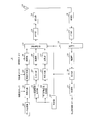
- FIG. 2 is a block diagram illustrating a configuration of the base station 100 according to Embodiment 1 of the present disclosure.
- base station 100 includes control section 101, data generation section 102, coding section 103, retransmission control section 104, modulation section 105, higher control signal generation section 106, coding section 107, , Modulation section 108, downlink control signal generation section 109, encoding section 110, modulation section 111, signal allocation section 112, IFFT (Inverse Fast Fourier Transform) section 113, transmission section 114, antenna 115, , A reception unit 116, an FFT (Fast Fourier Transform) unit 117, an extraction unit 118, a demodulation unit 119, a decoding unit 120, and a determination unit 121.
- FFT Fast Fourier Transform
- Control section 101 determines information related to downlink data transmission of terminal 200, and outputs the determined information to encoding section 103, modulation section 105, and signal allocation section 112.
- the information on downlink data transmission includes, for example, a modulation and coding method for downlink data transmitted on the PDSCH (for example, MCS) or a PDSCH radio resource (hereinafter, referred to as a “PDSCH resource”).
- control section 101 outputs the determined information to downlink control signal generation section 109.
- control unit 101 determines information on the reliability of the downlink data of the terminal 200, the delay request or the type of use case (or service) (in other words, information on the request condition of the response signal), and determines the determined information. It outputs to upper control signal generator 106 or downlink control signal generator 109. This information is notified to the terminal 200 (for example, the control unit 211).
- control section 101 determines information related to transmission of uplink control information (UCI: Uplink ⁇ Control ⁇ Information) of terminal 200, and outputs the determined information to extraction section 118 and decoding section 120. Further, control section 101 outputs information on UCI transmission to upper control signal generation section 106 or downlink control signal generation section 109.
- the information related to UCI transmission includes, for example, a UCI (for example, a response signal or CSI) or a PUCCH transmission method or parameters used for UCI transmission.
- the information output to the higher-level control signal generation unit 106 includes, for example, information on PUCCH resource set and a slot position set semi-statically (for example, PDSCH-to-HARQ-ACK timing). , Or information on the maximum coding rate of UCI.
- information for indicating a radio resource (hereinafter, PUCCH resource) of a PUCCH actually used in the PUCCH resource set, which is set quasi-statically Information for instructing PDSCH-to-HARQ-ACK timing that is actually used in the set of slot positions is included.
- control unit 101 determines and determines a radio resource assignment for a downlink control signal for transmitting a control signal (upper control signal) of a higher layer or a downlink control information, and a radio resource assignment for downlink data.
- the information thus output is output to signal assignment section 112.
- Data generating section 102 generates downlink data for terminal 200 and outputs the data to encoding section 103.
- the coding unit 103 performs error correction coding on the downlink data input from the data generation unit 102 based on information input from the control unit 101 (for example, information on a coding rate).
- the subsequent data signal is output to retransmission control section 104.
- retransmission control section 104 holds the encoded data signal input from encoding section 103 and outputs the signal to modulation section 105. Further, when NACK for the transmitted data signal is input from determination section 121 described later, retransmission control section 104 outputs the corresponding held data to modulation section 105. On the other hand, when ACK for the transmitted data signal is input from determination section 121, retransmission control section 104 deletes the corresponding held data.
- Modulation section 105 modulates a data signal input from retransmission control section 104 based on information input from control section 101 (for example, information on a modulation scheme), and outputs a data modulation signal to signal allocation section 112. I do.
- the higher control signal generation unit 106 generates a control information bit sequence (higher control signal) using the control information input from the control unit 101, and outputs the generated control information bit sequence to the encoding unit 107.
- Encoding section 107 performs error correction encoding on the control information bit sequence input from higher control signal generation section 106 and outputs the encoded control signal to modulation section 108.
- Modulating section 108 modulates the control signal input from encoding section 107 and outputs the modulated control signal to signal allocating section 112.
- Downlink control signal generation section 109 generates a control information bit sequence (downlink control signal; for example, DCI) using control information input from control section 101 and outputs the generated control information bit sequence to encoding section 110. . Since the control information may be transmitted to a plurality of terminals, the downlink control signal generation unit 109 may generate a bit string including the terminal ID of each terminal in the control information for each terminal. Note that a scrambling sequence to be described later may be used for the terminal ID.
- Encoding section 110 performs error correction encoding on the control information bit sequence input from downlink control signal generation section 109, and outputs the encoded control signal to modulation section 111.
- Modulation section 111 modulates the control signal input from encoding section 110 and outputs the modulated control signal to signal allocation section 112.
- the signal allocating unit 112 receives the data signal input from the modulation unit 105, the higher control signal input from the modulation unit 108, or the input from the modulation unit 111 based on the information indicating the radio resource input from the control unit 101.
- the downlink control signal to be mapped is mapped to a radio resource.
- Signal allocating section 112 outputs the downlink signal on which the signal is mapped to IFFT section 113.
- IFFT section 113 performs transmission waveform generation processing such as OFDM on the signal input from signal allocation section 112. IFFT section 113 adds a CP (not shown) in the case of OFDM transmission to which a CP (Cyclic @ Prefix) is added. IFFT section 113 outputs the generated transmission waveform to transmitting section 114.
- Transmitting section 114 performs RF (Radio Frequency) processing such as D / A (Digital-to-Analog) conversion and up-conversion on the signal input from IFFT section 113, and wirelessly transmits to terminal 200 via antenna 115. Send a signal.
- RF Radio Frequency
- the receiving unit 116 performs RF processing such as down-conversion or A / D (Analog-to-Digital) conversion on the uplink signal waveform received from the terminal 200 via the antenna 115, and performs the reception processing.
- RF processing such as down-conversion or A / D (Analog-to-Digital) conversion
- An uplink signal waveform is output to FFT section 117.
- FFT section 117 performs an FFT process on the uplink signal waveform input from receiving section 116 to convert a time domain signal into a frequency domain signal. FFT section 117 outputs the frequency domain signal obtained by the FFT processing to extraction section 118.
- Extraction section 118 extracts a radio resource component to which a PUCCH has been transmitted from a signal input from FFT section 117 based on information input from control section 101 (for example, information on UCI transmission). Extraction section 118 outputs the extracted radio resource component to demodulation section 119.
- Demodulation section 119 performs equalization and demodulation on the radio resource component corresponding to the PUCCH input from extraction section 118, and outputs a demodulation result (demodulation sequence) to decoding section 120.
- the decoding unit 120 performs error correction decoding on the demodulation result input from the demodulation unit 119 based on the information on UCI transmission input from the control unit 101 (for example, information on UCI encoding), and performs decoding.
- the subsequent bit sequence is output to determination section 121.
- the determining unit 121 determines whether the response signal transmitted from the terminal 200 indicates ACK (with error) or NACK (without error) for the transmitted data signal based on the bit sequence input from the decoding unit 120. Is determined. Determination section 121 outputs the determination result to retransmission control section 104.
- FIG. 3 is a block diagram illustrating a configuration of terminal 200 according to Embodiment 1 of the present disclosure.
- terminal 200 includes antenna 201, reception section 202, FFT section 203, extraction section 204, downlink control signal demodulation section 205, decoding section 206, upper control signal demodulation section 207, decoding section 208, a data demodulation unit 209, a decoding unit 210, a control unit 211, an encoding unit 212, a modulation unit 213, a signal allocation unit 214, an IFFT unit 215, and a transmission unit 216.
- the receiving unit 202 performs down conversion or A / D (Analog-to-Digital) conversion on a signal waveform of a downlink signal (data signal or control signal) from the base station 100 received via the antenna 201. And outputs the obtained received signal (baseband signal) to the FFT section 203.
- a / D Analog-to-Digital
- the FFT unit 203 performs an FFT process on the signal (time domain signal) input from the receiving unit 202 to convert the time domain signal into a frequency domain signal.
- FFT section 203 outputs the frequency domain signal obtained by the FFT processing to extraction section 204.
- the extracting unit 204 converts a signal input from the FFT unit 203 into a downlink control signal (for example, DCI) based on control information (for example, information on radio resources of downlink data or a control signal) input from the control unit 211. ), And extract a higher control signal or downlink data.
- Extraction section 204 outputs a downlink control signal to downlink control signal demodulation section 205, outputs an upper control signal to upper control signal demodulation section 207, and outputs downlink data to data demodulation section 209.
- the downlink control signal demodulation unit 205 equalizes and demodulates the downlink control signal input from the extraction unit 204, and outputs the demodulation result to the decoding unit 206.
- Decoding section 206 performs error correction decoding using the demodulation result input from downlink control signal demodulation section 205 to obtain control information. Decoding section 206 outputs the obtained control information to control section 211.
- the higher control signal demodulation unit 207 equalizes and demodulates the higher control signal input from the extraction unit 204, and outputs the demodulation result to the decoding unit 208.
- Decoding section 208 performs error correction decoding using the demodulation result input from higher order control signal demodulation section 207 to obtain control information. Decoding section 208 outputs the obtained control information to control section 211.
- Data demodulation section 209 equalizes and demodulates downlink data input from extraction section 204 and outputs a decoding result to decoding section 210.
- Decoding section 210 performs error correction decoding using the demodulation result input from data demodulation section 209. Further, decoding section 210 performs error detection on downlink data and outputs an error detection result to control section 211. Further, decoding section 210 outputs downlink data determined as having no error as a result of the error detection, as reception data.
- the control unit 211 uses UCI (for example, ACK / NACK or CSI) or UCI transmission based on information related to UCI transmission of the terminal 200 included in the control information input from the decoding unit 206 or the decoding unit 208.
- a PUCCH transmission method or parameter (for example, MCS or radio resource) is determined.
- Control section 211 outputs the determined information to encoding section 212, modulation section 213, and signal allocation section 214.
- Control section 211 generates a response signal (ACK / NACK) using the error detection result input from decoding section 210, and outputs the generated response signal to encoding section 212.
- control unit 211 outputs to the extraction unit 204 information on the radio resource of the downlink data or the control signal included in the control information input from the decoding unit 206 or the decoding unit 208.
- Encoding section 212 performs error correction encoding on the response signal (ACK / NACK bit sequence) based on the information input from control section 211, and outputs the encoded response signal (bit sequence) to modulation section 213. I do.
- the encoding unit 212 applies a different encoding method to response signals having different request conditions such as reliability, a delay request, or a type of use case (or service) to apply an encoded bit sequence. May be generated.
- Modulating section 213 modulates the response signal input from encoding section 212 based on the information input from control section 211, and outputs a modulated response signal (modulated symbol sequence) to signal allocating section 214.
- the modulation unit 213 modulates each encoded bit sequence.
- Signal allocating section 214 maps the response signal (modulated symbol sequence) input from modulating section 213 to the radio resource of PUCCH specified by control section 211.
- Signal allocating section 214 outputs the signal on which the response signal is mapped to IFFT section 215.
- IFFT section 215 performs transmission waveform generation processing such as OFDM on the signal input from signal allocation section 214.
- IFFT section 215 adds a CP (not shown) in the case of OFDM transmission to which a CP (Cyclic @ Prefix) is added.
- a DFT Discrete Fourier Transform
- IFFT section 215 outputs the generated transmission waveform to transmitting section 216.
- the transmitting unit 216 performs RF (Radio Frequency) processing such as D / A (Digital-to-Analog) conversion and up-conversion on the signal input from the IFFT unit 215, and transmits the signal to the base station 100 via the antenna 201. Transmit radio signals.
- RF Radio Frequency
- FIG. 4 shows a processing flow of base station 100 and terminal 200 according to the present embodiment.
- Base station 100 transmits information on PUCCH to terminal 200 (ST101).
- Terminal 200 acquires information on PUCCH notified from base station 100 (ST102).
- the information on PUCCH includes, for example, information on PUCCH ⁇ resource ⁇ set or information on the coding rate of PUCCH.
- Base station 100 transmits DCI including information on downlink data to terminal 200 (ST103).
- Terminal 200 acquires, for example, scheduling information of downlink data or information on PUCCH based on the DCI notified from base station 100 (ST104).
- Base station 100 transmits downlink data to terminal 200 (ST105).
- Terminal 200 receives, for example, downlink data (PDSCH) based on the DCI notified from base station 100 (ST106).
- PDSCH downlink data
- Terminal 200 controls the operation related to the transmission of the response signal or the response signal according to the request condition for the response signal (in other words, the reliability, the delay request, or the type of use case (service)) (ST107). For example, terminal 200 determines a processing mode for the response signal or the PUCCH according to a request condition for the response signal. In determining the processing mode for the response signal or the PUCCH, for example, a coding method of the response signal, a PUCCH resource determination method, a parameter related to PUCCH transmission, or the like may be determined.
- Terminal 200 transmits UCI (for example, including a response signal) to base station 100 using PUCCH based on the determined operation (ST108).
- Base station 100 receives the UCI transmitted from terminal 200 (ST109).
- the terminal 200 applies a different coding method to response signals having different types of reliability, delay request, or use case (or service) (in other words, response signals having different request conditions), and performs HARQ- Generate an ACK bit.
- terminal 200 multiplexes the response signal after encoding to which a different encoding method is applied to PUCCH and transmits the PUCCH.
- the terminal 200 applies encoding processing with different encoding rates to response signals having different types of reliability, delay request, or use case (or service).
- the terminal 200 encodes the response signal using a low coding rate (for example, a coding rate equal to or less than a threshold) with respect to the response signal requiring high reliability, and generates a HARQ-ACK bit. .
- a low coding rate for example, a coding rate equal to or less than a threshold
- the reliability of the response signal can be improved.
- the terminal 200 encodes the response signal using a high coding rate (for example, a coding rate higher than a threshold) for the response signal for which high reliability is not required, and generates a HARQ-ACK bit.
- a high coding rate for example, a coding rate higher than a threshold
- a difference may be caused in the encoding process between the response signal to the downlink data.
- the target error rate of the first data transmission is high, a high reliability is required for the response signal in order to surely retransmit the data. Is applied.
- the target error rate of the first data transmission is low, data errors are unlikely to occur, so that the response signal is not required to have such high reliability. Is applied.
- FIG. 5 shows an example in which different encoding methods (encoding processes) are applied to a response signal between URLLC and eMBB.
- terminal 200 applies encoding process 1 (encoding process 1) to a response signal to eMBB downlink data (eMBB @ PDSCH), and responds to a response signal to URLLC downlink data (URLLC @ PDSCH).
- encoding process 2 encoding ⁇ process ⁇ 2).
- terminal 200 generates HARQ-ACK bits by applying different encoding methods to the URLLC response signal and the eMBB response signal, respectively, and multiplexes the generated HARQ-ACK bits into one PUCCH. And transmits it to base station 100.
- terminal 200 performs an appropriate encoding method (for example, encoding) for each response signal in accordance with the reliability of the response signal, the delay request, or the type of use case (or service). Conversion rate) can be applied. As a result, even when the requirements of the response signals multiplexed on one PUCCH are different, each response signal is encoded using an encoding method corresponding to the requirements of each response signal. Thus, efficient PUCCH transmission becomes possible.
- an appropriate encoding method for example, encoding
- Conversion rate can be applied.
- the encoding process different for each ACK / NACK is not limited to the case where the encoding process is determined based on the above-described reliability or the type of use case (service).
- the reliability, the delay request, or the use case (The service may be determined based on at least one of the types.
- mapping method Next, a method of mapping response signals having different types of reliability, delay request, or use case (or service) (in other words, response signals having different request conditions) to PUCCH resources will be described.
- the terminal 200 maps the PUCCH in the order of the response signals requiring higher reliability or in the order of the response signals requiring lower delay in the delay request. Specifically, terminal 200 first maps a response signal requiring higher reliability or lower delay to a PUCCH resource. Next, terminal 200 maps a response signal that does not require high reliability or low delay to a PUCCH resource.
- response signals in a Short-PUCCH composed of one or two symbols for example, PUCCH Format 2
- a Long-PUCCH composed of four or more symbols for example, PUCCH Format 3 or PUCCH Format 4
- Option 1 and Option 2 can be applied to the mapping of the response signal in the Short PUCCH to the PUCCH resource.
- FIG. 6 shows an example of mapping response signals to REs (Resource Elements) in Option 1.
- terminal 200 converts the modulated symbol sequence after modulating the response signal (HARQ-ACK) into a reference signal (RS-RS) based on the "Frequency-first-time-second format".
- RS-RS reference signal
- ⁇ Reference ⁇ Signal for example, mapping to the RE except for the resource element (RE: ⁇ Resource ⁇ Element) to which DMRS: Demodulation ⁇ RS is mapped.
- terminal 200 maps the response signal in the PUCCH in order from the frequency direction to the time direction.
- a response signal requiring high reliability or low delay (in FIG. 6, HARQ-ACK for URLLC) is first mapped to the PUCCH resource, and subsequently , A response signal that does not require high reliability or low delay (in FIG. 6, HARQ-ACK for eMBB) is mapped to PUCCH resources.
- HARQ-ACK for URLLC includes all REs of the first symbol constituting the PUCCH (excluding the RE to which the DMRS is mapped) and a part of the second symbol.
- the HARQ-ACK for the eMBB, which is mapped to the RE, is mapped to the remaining RE of the second symbol.
- mapping method of ⁇ Option ⁇ 1 for example, a response signal requiring a lower delay is mapped to the first symbol of the PUCCH. Therefore, in the case of Short @ PUCCH of two symbols, a delay reduction effect can be obtained.
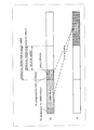
- FIG. 7 shows an example of mapping response signals to REs in Option 2.
- terminal 200 converts the modulation symbol sequence after modulating the response signal (HARQ-ACK) based on the "Frequency-first-time-second format" as in Option # 1. , To the REs except for the RE to which the reference signal is mapped. Further, in Option # 2, terminal 200 performs mapping such that response signals in the allocated band are dispersed in the frequency direction.
- a response signal requiring high reliability or low delay (in FIG. 7, HARQ-ACK for URLLC) is first mapped to the PUCCH resource, and subsequently , A response signal that does not require high reliability or low delay (in FIG. 7, HARQ-ACK for eMBB) is mapped to PUCCH resources.
- ACK / NACK for URLLC and ACK / NACK corresponding to eMBB are mapped in a dispersed manner in the frequency direction.
- HARQ-ACK for URLLC includes all REs of the first symbol constituting the PUCCH (excluding the RE to which the DMRS is mapped) and a part of the second symbol.
- the HARQ-ACK for the eMBB which is mapped to the RE, is mapped to the remaining RE of the second symbol.
- the HARQ-ACK for URLLC and the HARQ-ACK for eMBB are distributed and mapped in the frequency direction in the allocated band of PUCCH (for example, 4 RBs (Resource @ Block)). I have.
- the mapping method of Option # 2 similarly to the mapping method of Option # 1, the response signal requiring a lower delay is mapped to the first symbol of the PUCCH. Therefore, in the case of Short @ PUCCH of two symbols, the delay reduction effect is achieved. Is obtained.
- a frequency diversity effect can be obtained by dispersive mapping in the frequency direction, so that a higher quality response signal (in other words, a higher reliability response signal) can be obtained. Transmission can be realized.
- ⁇ Long PUCCH> The following two methods (Option 3 and Option 4) can be applied to mapping the response signal to the PUCCH resource in Long-PUCCH.
- Option 3 a method similar to the mapping relationship between HARQ-ACK bits and CSI (CSI Part 1 and CSI Part 2) in NR PUCCH Format 3 or PUCCH Format 4 (for example, see Non-Patent Document 2) is reliable. The method is applied to mapping for response signals having different types of delay requests or use cases (or services).
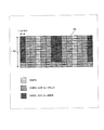
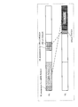
- FIG. 8 shows an example of mapping response signals to REs in Option # 3.
- terminal 200 converts the modulated symbol sequence after modulating the response signal (HARQ-ACK) into RS (FIG. 8) based on the "Frequency-first-time-second format". Then, the mapping is mapped to the RE except the RE to which the DMRS is mapped. Also, as shown in FIG. 8, terminal 200 maps a response signal requiring higher reliability to a symbol closer to a symbol to which a reference signal (eg, DMRS) is mapped in PUCCH.
- a reference signal eg, DMRS
- the HARQ-ACK for the URLLC that requires high reliability is a symbol (a symbol close to the symbol to which the DMRS is mapped) (Symbols before and after).
- HARQ-ACK bits for eMBBs for which high reliability is not so required are mapped to the remaining PUCCH resources.
- HARQ-ACK bits requiring higher reliability are mapped to symbols with high channel estimation accuracy (symbols close to symbols to which DMRS is mapped). For this reason, according to Option # 3, transmission of a higher quality response signal (in other words, a higher reliability response signal) can be realized.
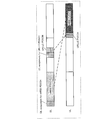
- FIG. 9 shows an example of mapping response signals to REs in Option 4.
- terminal 200 maps the modulation symbol sequence after modulating the response signal (HARQ-ACK) based on the “Frequency-first-time-second format” to the RS. Mapping to the RE excluding the RE Also, as shown in FIG. 9, terminal 200 maps a response signal for which a lower delay is required in a delay request to a symbol earlier in the PUCCH.
- the HARQ-ACK for the URLLC for which low delay is required first starts from the symbol with the earlier timing (for example, the first symbol). Are mapped in order. Subsequently, as shown in FIG. 9, HARQ-ACKs for eMBBs that do not require much low delay are mapped to the remaining PUCCH resources.
- mapping method of ⁇ Option ⁇ 4 since a response signal requiring a lower delay is mapped to the first symbol of the PUCCH, there is an effect of reducing delay.
- mapping response signals to PUCCH resources has been described.
- terminal 200 preferentially maps a response signal requiring high reliability or low delay, that is, a response signal having strict requirements, to a PUCCH resource. Thereby, the terminal 200 preferentially assigns, for example, among the response signals multiplexed on the PUCCH, a response signal requiring higher reliability or lower delay to a PUCCH resource capable of achieving higher reliability or lower delay. Can be mapped. Therefore, according to the present embodiment, terminal 200 can transmit a response signal using a PUCCH resource suitable for a request condition for the response signal.
- Option # 3 and Option # 4 a method of mapping a response signal to Long-PUCCH using four or more symbols has been described.
- using Long-PUCCH is not desirable from the viewpoint of delay reduction. Therefore, in the present embodiment, the multiplexing of response signals having different types of reliability, delay requests, or use cases (or services) on one PUCCH may be limited to the Short-PUCCH. This makes it possible to omit the design for a plurality of PUCCH formats while satisfying the requirement of low delay.
- the method of mapping the response signal to the PUCCH resource is not limited to Option # 1 to Option # 4. Further, for example, any one of Option # 1 to Option # 4 may be combined. For example, in Option # 3 (see FIG. 8) or Option # 4 (see FIG. 9), the response signal (HARQ-ACK) is distributed and mapped in the frequency direction like Option # 2 (see FIG. 7). You may.
- the base station uses a terminal-specific upper layer signal (for example, RRC (Radio Resource Control) signaling) to generate a quasi-static signal.
- RRC Radio Resource Control
- a method of notifying a set of PUCCH resources (PUCCH resource set) and notifying a PUCCH resource actually used in the PUCCH resource set by DCI (Downlink Control Information) that allocates downlink data is adopted (for example, see Non-Patent Documents). 3).
- the PUCCH resource includes, for example, the symbol position in the slot, the number of symbols in the slot, the frequency domain position, the number of resources in the frequency domain (for example, the number of RBs or the number of PRBs (Physical RB)), and whether or not frequency hopping is applied.
- a parameter consisting of at least one of code resources for example, a cyclic shift sequence or an orthogonal code.
- the base station can notify the terminal of a plurality of PUCCH resource sets.
- the terminal can determine which PUCCH resource set among the plurality of notified PUCCH resource sets based on the number of bits of uplink control information (UCI: Uplink Control Information) transmitted using the PUCCH.
- UCI Uplink Control Information
- terminal 200 determines PUCCH resource ⁇ ⁇ ⁇ set based on the total number of encoded bits of a response signal (HARQ-ACK) multiplexed on PUCCH.
- HARQ-ACK response signal
- the maximum coding rate is set for each PUCCH format.
- the terminal determines the number of RBs used for PUCCH transmission from the number of UCI bits transmitted using PUCCH and the maximum coding rate.
- the upper limit is the number of RBs of PUCCH resources notified by the above PUCCH ⁇ resource ⁇ set.
- the maximum coding rate is set for each PUCCH format and for each type of response signal reliability, delay request or use case (or service) (in other words, each response signal request condition).
- the terminal 200 determines the number of bits after encoding the response signal and the set maximum coding rate. Based on this, the resource amount (for example, the number of REs) used for transmitting the response signal is calculated. Then, terminal 200 determines the number of RBs used for transmitting the PUCCH based on the number of REs used for transmitting each response signal multiplexed on one PUCCH.
- the resource amount for example, the number of REs
- terminal 200 for example, as described above, based on the number of bits after encoding by the encoding method set for each response signal, PUCCH ⁇ resource ⁇ set in PUCCH in which response signals having different requirements are multiplexed. Can be determined. For example, the terminal 200 can calculate an appropriate resource amount according to the reliability of the response signal, the delay request, or the type of use case (or service), so that efficient PUCCH transmission can be performed from the viewpoint of resource utilization efficiency. .
- the upper limit of the number of RBs used for PUCCH transmission is the number of RBs of PUCCH resources notified by PUCCH ⁇ resource ⁇ set. Therefore, for example, if the number of RBs determined from the number of bits of the response signal and the maximum coding rate exceeds the upper limit value notified by PUCCH resource set, the actual coding rate of the response signal is set May exceed the set maximum coding rate. In this case, there is a possibility that the quality required for PUCCH transmission cannot be satisfied.
- terminal 200 may drop a part of the response signal transmitted using PUCCH.
- PUCCH resources resources obtained by dropping a part of the response signal are used for the remaining response signals, so that the quality of PUCCH transmission can be improved.
- the threshold value may be, for example, the maximum coding rate set for each PUCCH format and for each type of response signal reliability, delay request, or use case (or service).
- a threshold value for dropping some response signals may be newly notified from the base station 100 to the terminal 200.
- terminal 200 uses PUCCH when the number of RBs calculated from the number of bits of the response signal (or UCI) transmitted using PUCCH and the maximum coding rate exceeds a predetermined threshold (upper limit). At least a part of the response signal to be transmitted may be dropped.
- a predetermined threshold upper limit
- the response signal to be dropped depends on the reliability of the response signal, the priority set according to the type of the delay request or the use case (or service) (in other words, the priority set for each request condition). It may be determined. For example, the terminal 200 may preferentially transmit a response signal of a high priority request condition. In other words, the terminal 200 may preferentially drop a response signal of a low priority request condition.
- the priority of URLLC is set higher than the priority of eMBB.
- terminal 200 may drop response signals with lower priority. As a result, it is possible to suppress the deterioration of the transmission quality of a response signal having a high priority, that is, a response signal requiring higher reliability.
- resource @ sharing @ factor or resource @ splitting @ factor may be notified from the base station 100 to the terminal 200 in advance.
- terminal 200 performs processing on a response signal or a PUCCH according to a request condition (eg, reliability, delay request, or type of use case (service)) for a response signal of downlink data.
- a request condition eg, reliability, delay request, or type of use case (service)
- terminal 200 applies different encoding methods to response signals having different request conditions.
- terminal 200 multiplexes the encoded response signal on the PUCCH and transmits the multiplexed response signal.
- terminal 200 performs processing according to the requirements required for the response signal multiplexed on the PUCCH (for example, Encoding processing) or setting of radio resources (for example, determination of a mapping method or PUCCH resources) can be performed.
- terminal 200 can improve the PUCCH resource utilization efficiency by setting the position or amount of the PUCCH resource according to the reliability required for the response signal.
- terminal 200 can reduce the delay of the response signal by setting the position of the PUCCH resource according to the delay request for the response signal.
- terminal 200 can appropriately transmit UCI including a response signal.
- the base station and the terminal according to the present embodiment have the same basic configuration as base station 100 and terminal 200 according to the first embodiment, and thus will be described with reference to FIGS.
- terminal 200 receives PUCCH resources or PUCCH resource sets for response signals having different types of reliability, delay request, or use case (or service) (in other words, response signals having different request conditions). Different decision methods.
- the number of PUCCHs to which terminal 200 can transmit a response signal in one slot is not limited to one. In other words, in the present embodiment, the number of PUCCHs to which terminal 200 can transmit a response signal in one slot is one or more.
- the terminal 200 transmits each response signal having a different requirement using a different PUCCH in a slot.
- a plurality of PUCCHs are multiplexed in the same slot by time division multiplexing (TDM: Time Division Multiplexing), frequency division multiplexing (FDM: Frequency Division Division Multiplexing), or code division multiplexing (CDM: Code Division Division Multiplexing).
- terminal 200 can allocate an appropriate PUCCH resource for each response signal according to the reliability of the response signal, the delay request, or the type of use case (or service).
- the terminal 200 can transmit response signals having different request conditions by using individual PUCCHs without multiplexing them into one PUCCH. For this reason, efficient PUCCH transmission becomes possible from the viewpoint of resource utilization efficiency.
- terminal 200 can transmit response signals with different delay requests using different PUCCHs, for example. For this reason, for example, by using a Short-PUCCH to transmit a response signal that requires a low delay such as URLLC, and by transmitting a response signal that does not require a long delay such as eMBB using a Long-PUCCH Thus, a bottleneck for a delay request can be eliminated.
- the base station 100 uses a terminal-specific upper layer signal (for example, RRC signaling) to generate a set of quasi-static PUCCH resources (for example, RRC signaling). For example, PUCCH (resource set) is notified.
- the terminal 200 determines the PUCCH resource set based on, for example, one of the following two methods (Option # 1 and Option # 2).
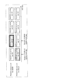
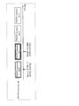
- FIG. 10A shows a setting example of PUCCH resource set in Option # 1.
- a group of PUCCH resource set for eMBB for example, group X
- a group of PUCCH resource set for URLLC for example, group Y
- group X includes PUCCH resource set X0, X1, X2, and X3
- group Y includes PUCCH resource set Y0, Y1, Y2, and Y3.
- the terminal 200 for example, for each response signal of different types of reliability, delay request or use case (or service), based on the number of UCI bits transmitted using PUCCH (eg, the number of HARQ-ACK bits) Decide which PUCCH resource set within each group to use.
- terminal 200 selects PUCCH resource set X1 from PUCCH resource set in group X based on the number of bits of the response signal to the eMBB.
- terminal 200 selects PUCCH ⁇ resource ⁇ set ⁇ Y0 from PUCCH ⁇ resource ⁇ set in group Y based on the number of bits of the response signal to URLLC.
- terminal 200 assigns DCI (e.g., DL @ assignment @ for @ eMBB or DL @ assignment shown in FIG. 10B) for assigning downlink data corresponding to each of response signals having different types of reliability, delay request, or use case (or service).
- DCI e.g., DL @ assignment @ for @ eMBB or DL @ assignment shown in FIG. 10B
- terminal 200 transmits a response signal using the PUCCH resource notified by the DCI among the selected PUCCH resource set.
- PUCCH resource set is set individually for each type of reliability, delay request, or use case (or service), so responses with different reliability, delay request, or use case (or service) type PUCCH resources suitable for signals can be allocated more flexibly.
- the setting example of the PUCCH ⁇ resource ⁇ set shown in FIG. 10A is an example, and is not limited.
- the number of PUCCH resource set included in the group of PUCCH resource set for eMBB and URLLC is not limited to four, and may be another number. Further, the number of PUCCH resource set included in each group of PUCCH resource set for eMBB and URLLC may be the same or different.
- eMBB and URLLC are described as an example of a case where the request conditions are different, but the present invention is not limited to this.
- a PUCCH ⁇ resource ⁇ set It may be set.
- the same PUCCH resource set group is set for response signals having different types of reliability, delay request, or use case (or service) (in other words, response signals having different request conditions). Therefore, terminal 200 sets PUCCH resource sets included in the same group for response signals having different request conditions.
- FIG. 11A shows a setting example of PUCCH ⁇ resource ⁇ set in Option # 2.
- groups including PUCCH resource set 0, # 1, # 2, and 3 are set.
- the terminal 200 may, for example, be in the same group based on the number of UCI bits transmitted using the PUCCH (eg, the number of HARQ-ACK bits) regardless of the type of reliability, delay request, or use case (or service). Which PUCCH resource set to use.
- terminal 200 selects PUCCH resource set 1 from PUCCH resource set 0 to 3 based on the number of bits of the response signal to the eMBB. Also, in FIG. 11A, terminal 200 selects PUCCH resource set 0 from PUCCH resource set 0 to 3 based on the number of bits of the response signal to URLLC.
- terminal 200 assigns DCI (e.g., DL @ assignment @ for @ eMBB or DL @ assignment shown in FIG. 11B) that assigns downlink data corresponding to each of response signals having different types of reliability, delay request, or use case (or service).
- DCI e.g., DL @ assignment @ for @ eMBB or DL @ assignment shown in FIG. 11B
- terminal 200 transmits a response signal using the PUCCH resource notified by the DCI among the selected PUCCH resource set.
- the selectable PUCCH ⁇ resource ⁇ set is the same regardless of the type of reliability, delay request, or use case (or service). For this reason, it is possible to reduce the overhead related to the notification of the PUCCH ⁇ resource ⁇ set.
- Terminal 200 ⁇ can individually determine a PUCCH ⁇ resource ⁇ set to be actually used based on the number of bits of each response signal having different reliability, delay request, or use case (or service) type. Therefore, terminal 200 can use PUCCH resources suitable for response signals having different types of reliability, delay request, or use case (or service).
- terminal 200 applies different resource determination methods to response signals having different request conditions (for example, reliability, delay request, or use case (service) type). Then, terminal 200 transmits the response signal using the PUCCH resource set for each response signal.
- request conditions for example, reliability, delay request, or use case (service) type.
- terminal 200 can individually set radio resources according to the request conditions required for the response signal, thereby improving resource utilization efficiency or reducing the delay of the response signal it can.
- terminal 200 can appropriately transmit UCI including a response signal.
- terminal 200 may apply the same processing as in Embodiment 1.
- Option # 1 a case has been described where different PUCCH ⁇ resource ⁇ set groups are set for each type of reliability, delay request, or use case (or service).
- a difference may be caused in values (or value ranges) that can be set for each type of reliability, delay request, or use case (or service).
- PUCCH Format 0 of NR Sequence selection is used (for example, see Non-Patent Document 1).
- frequency allocation of one-cell repetition is used.
- inter-cell interference is the main factor of characteristic degradation.
- Short-PUCCH since the number of symbols used (one symbol or two symbols) is small, it is not possible to suppress inter-cell interference due to the effect of averaging interference by using a plurality of symbols.
- the number of RBs or the sequence length that can be set for the PUCCH may be varied according to response signals having different types of reliability, delay request, or use case (or service).
- a variable number of PRBs (for example, any of 1, 2, and 4 PRBs) may be settable.
- the number of PRBs that can be set may be 1 PRB.
- the number of PRBs that can be set for each request condition is not limited to the above example, and may be another number.
- the number of PUCCH configurable Repetitions may be made different according to response signals having different reliability, delay request, or type of use case (or service).
- Repetition may be set, and a variable number of repetitions (for example, any one of 1, 2, and 4) may be set.
- a variable number of repetitions for example, any one of 1, 2, and 4
- Repetition cannot be set. Note that the number of Repetitions that can be set for each request condition is not limited to the above example, and may be another number.
- the Repetition in the time domain there is a method of repeatedly transmitting the same sequence over a plurality of symbols.
- this method by performing in-phase synthesis of the Repetition signal on the receiving side (for example, the base station 100), it is possible to expect a characteristic improvement effect by improving the power of the received signal.
- the sequence length is expanded from 12 to 24, the first half of the sequence length 24 is transmitted with the first symbol, and the latter half is transmitted with the next symbol. In this method, the effect of interference suppression by using a long sequence length can be expected.
- Embodiment 2 has described the case where PUCCH resources or PUCCH resource set determination methods are made different for response signals having different types of reliability, delay requests, or use cases (or services).
- the terminal uses the terminal specific to the terminal regarding the specification of the PUCCH slot position (or the time from the slot receiving the downlink data to the slot transmitting the PUCCH) for transmitting the response signal to the downlink data.
- a method is used in which a set of quasi-static slot positions is notified by an upper layer signal (for example, RRC signaling), and a slot position actually used in the set of slot positions is notified by a DCI that allocates downlink data. (For example, see Non-Patent Document 3).
- a set of PUCCH slot positions for transmitting a response signal similarly has a different response signal having different reliability, delay request, or use case (or service) type (in other words, It can be set for each of the response signals having different request conditions.
- terminal 200 can use an appropriate transmission slot for a response signal according to the reliability of the response signal, the delay request, or the type of use case (or service). For example, if different sets of slot positions are set for different delay requests, terminal 200 transmits each of the response signals having different delay requests using different PUCCHs. In contrast, more flexible slot assignment suitable for a delay request becomes possible.
- the base station and the terminal according to the present embodiment have the same basic configuration as base station 100 and terminal 200 according to the first embodiment, and thus will be described with reference to FIGS.
- the terminal 200 in the same slot, when simultaneously transmitting a response signal for data transmission of different types of reliability, delay request or use case (or service), according to the priority of PUCCH, Drop all or partially puncture PUCCH that transmits the response signal.
- PUCCH for dropping or partially puncturing may be determined based on the reliability of ACK / NACK, a delay request, or a priority given according to the type of use case (or service).
- the terminal 200 drops or punctures all PUCCHs with lower priorities based on the requirements.
- FIG. 12 shows a case where two services, URLLC and eMBB, exist.
- the priority of the PUCCH corresponding to URLLC is set higher than the priority of the PUCCH corresponding to eMBB. That is, terminal 200 drops or punctures all PUCCHs corresponding to the eMBB.
- the terminal 200 transmits a response signal corresponding to URLLC using a PUCCH corresponding to URLLC (URLLC PUCCH), and drops all PUCCH corresponding to eMBB (eMBB PUCCH).
- the method of puncturing symbols that overlap in time is performed, for example, when the terminal 200 cannot simultaneously transmit a plurality of uplink signals or when the terminal 200 has a capability of simultaneously transmitting a plurality of uplink signals, Can exceed the maximum transmission power, and can be applied to a case where one of the signals must be transmitted.
- a method of puncturing an RE in which time and frequency overlap with each other is, for example, capable of transmitting a plurality of uplink signals to the terminal 200 at the same time. Applicable when the power is not exceeded.
- Embodiment 4 For example, Embodiment 1 has described the case where different encoding processes are applied to response signals having different types of reliability, delay request, or use case (or service). However, performing different encoding processes may increase the processing amount of the terminal, and may complicate the implementation.
- the base station and the terminal according to the present embodiment have the same basic configuration as base station 100 and terminal 200 according to Embodiment 1, and thus will be described with reference to FIGS.
- the terminal 200 has a capability (UE capability; hereinafter, referred to as “N1”) relating to a processing time required for decoding downlink data, generating a response signal, and transmitting a PUCCH after receiving downlink data.
- N1 UE capability
- terminal 200 reports “N1” to base station 100.
- the base station 100 transmits the PUCCH slot position for transmitting the response signal to the downlink data by the terminal 200 (or the time from the slot receiving the downlink data to the slot transmitting the PUCCH (for example, the response signal): “ PDSCH-to-HARQ-ACK @ timing ”) and notifies terminal 200.
- the base station 100 cannot set and notify a value exceeding the processing capability (N1) of the terminal 200 reported from the terminal 200 (in other words, a value smaller than N1) for PDSCH-to-HARQ-ACK @ timing.
- the terminal 200 specifies the capability (N1) for transmitting response signals having different types of reliability, delay request, or use case (or service), and reports the same to the base station 100.
- terminal 200 transmits the PUCCH used for transmitting the response signal or the response signal based on the value of PDSCH-to-HARQ-ACK timing set and notified from base station 100 and the specified value of N1.
- parameters in other words, the processing mode for the response signal or PUCCH is determined.
- the terminal 200 receives the downlink data, decodes the data, generates a response signal, and processes the necessary processing time (N1) until transmitting the PUCCH. It has two or more capabilities depending on the type of case (or service). The terminal 200 reports two or more capabilities (N1) to the base station 100.
- the terminal 200 has two terminal capabilities (UE capability) of N1 for eMBB (hereinafter, referred to as “N1_X” or “N1_eMBB”) and N1 for URLLC (hereinafter, referred to as “N1_Y” or “N1_URLLC”). ).
- N1_X terminal capabilities
- N1_Y N1 for URLLC
- N1_Y URLLC
- N1_URLLC URLLC
- the base station 100 uses the terminal-specific upper layer.
- a set of quasi-static slot positions is notified by a signal (for example, RRC signaling), and which PDSCH-to-HARQ-ACK timing in the set is actually used is notified by a DCI that allocates downlink data.
- terminal 200 transmits the PDSCH-to-HARQ- for each response signal.
- the processing for the response signal is determined based on the value of ACK @ timing and the capability (N1) of terminal 200.
- the minimum value of the PDSCH-to-HARQ-ACK @ timing value for each response signal is N1 (N1_X or If N1_eMBB or more, the terminal 200 performs common encoding processing (joint @ encoding) on the response signal corresponding to eMBB and the response signal corresponding to URLLC, and generates a HARQ-ACK bit.
- the terminal 200 receives the PDSCH for URLLC and before the time corresponding to PDSCH-to-HARQ-ACK timing for URLLC elapses.
- the processing up to generation of the corresponding response signal and transmission of the PUCCH including the response signal can be completed (in other words, N1_X / N1_eMBBMB ⁇ ⁇ PDSCH-to-HARQ-ACK timing for URLLC). Therefore, the terminal 200 receives the URLLC response signal and the eMBB response signal after the terminal 200 receives the PDSCH for URLLC until the time corresponding to PDSCH-to-HARQ-ACKSCHtiming for URLLC elapses. And a common encoding process can be performed.
- a value of PDSCH-to-HARQ-ACK @ timing for a response signal requiring high reliability or low delay or a response signal corresponding to URLLC (in FIG. 14, PDSCH-to-HARQ If -ACK timing for URLLC is less than N1 (N1_X or N1_eMBB) corresponding to eMBB, terminal 200 performs common encoding processing on the response signal corresponding to eMBB and the response signal corresponding to URLLC. Can not do.
- the terminal 200 after the terminal 200 receives the PDSCH for URLLC and before the time corresponding to PDSCH-to-HARQ-ACK timing for URLLC elapses, the terminal 200 A process until a corresponding response signal is generated and a PUCCH including the response signal is transmitted cannot be completed (in other words, N1_X / N1_eMBB> PDSCH-to-HARQ-ACK timing for URLLC).
- the terminal 200 receives the ACK / NACK of the URLLC and the eMBB of the URLMB from the time when the terminal 200 receives the PDSCH for URLLC until the time corresponding to PDSCH-to-HARQ-ACK-timing for URLLC elapses.
- ACK / NACK cannot be collectively encoded.
- terminal 200 uses any of the methods in Embodiment 3 or Embodiment 1.
- the number of encoding processes can be reduced to one for response signals having different types of reliability, delay request, or use case (or service).
- the implementation of 200 can be simplified.
- terminal 200 performs appropriate coding (or code) according to the reliability of the response signal, the delay request, or the type of use case (or service). Since the HARQ-ACK bit can be generated based on the conversion rate), efficient PUCCH transmission can be performed from the viewpoint of resource utilization efficiency.
- code processing can be shared as much as possible according to the processing capability of terminal 200, so that the processing amount of terminal 200 can be increased or the complexity of implementation can be reduced.
- the reliability of the response signal may be different.
- the former response signal requires high reliability, while the latter response signal does not require very high reliability.
- a case where a delay request of the response signal is different or a use case (or service) is different.
- the former response signal requires high reliability or low delay, while the latter response signal does not require much higher reliability or low delay.
- examples of causing a difference in the transmission method of the response signal or the PUCCH are not limited to the types of the reliability, the delay request, or the use case (service), but may be, for example, different physical layer parameters.
- eMBB may be replaced with “transmission in slot units” and URLLC may be replaced with “transmission in non-slot units”.
- the eMBB may be replaced with “PDSCH mapping type A” or “PUSCH mapping type A”
- the URLLC may be replaced with “PDSCH mapping type B” or “PUSCH mapping type B”.
- the transmission is not limited to transmission corresponding to eMBB and URLLC.
- eMBB is replaced with transmission having a longer transmission interval (for example, slot length or symbol length)
- URLLC is replaced with transmission having a transmission interval shorter than the above transmission interval. You may.
- the target error rate may be the target error rate of the first data transmission as described above, or may be the target error rate in retransmission when retransmission occurs. Further, the target error rate may be referred to as an “instantaneous target error rate” in the sense of the target error rates of the first and retransmission.
- the method of determining the "type of reliability, delay request, or use case (or service)" (in other words, the required condition) of the response signal described in the above embodiment includes, for example, the following Example 1. -There is a method as in Example 5.
- Example 1 Scramble sequence
- the terminal 200 determines the reliability of the response signal, the delay request or the use case (service) based on the terminal-specific scrambling sequence used for DCI for scheduling downlink data transmission corresponding to each response signal. Judge the type.
- C-RNTI Cell-Radio Network Temporary Identifier
- CS-RNTI Configured Scheduling-RNTI
- the control unit 101 of the base station 100 determines information on the reliability of the downlink data of the terminal 200, the delay request, or the type of use case (service).
- the determined information is output to downlink control signal generation section 109 of base station 100.
- downlink control signal generating section 109 generates a DCI bit sequence using a scrambling sequence according to the reliability of downlink data of terminal 200, a delay request, or a type of use case (or service).
- decoding section 206 of terminal 200 (for example, see FIG. 3) outputs the detected scrambling sequence to control section 211.
- the control unit 211 determines information on the reliability of the downlink data, the delay request, or the type of use case (service) based on the obtained scrambling sequence.
- Example 2 MCS table
- the terminal 200 determines the reliability of the response signal, the delay request, or the type of use case (service) based on the MCS table used for scheduling the downlink data transmission corresponding to each response signal.
- terminal 200 determines that the reliability required for the response signal is high.
- terminal 200 determines that the reliability required for the response signal is not high.
- the control unit 101 of the base station 100 determines information on the reliability of the downlink data of the terminal 200, the delay request, or the type of use case (service). The determined information is output to downlink control signal generation section 109, coding section 103 and modulation section 105 of base station 100.
- Downlink control signal generation section 109 includes information on the MCS table used for downlink data transmission in the bit string of DCI. Encoding section 103 and modulation section 105 also encode and modulate downlink data using information on the MCS table input from control section 101.
- the decoding unit 206 of the terminal 200 decodes the DCI and outputs the decoding result to the control unit 211.
- the control unit 211 determines information on the reliability of the downlink data, delay request or type of use case (service) based on the information on the MCS table obtained from the DCI.
- Example 3 PDSCH-to-HARQ-ACK timing or PDSCH transmission symbols
- the terminal 200 determines the reliability of the response signal based on “PDSCH-to-HARQ-ACK timing” notified by the DCI that schedules downlink data transmission corresponding to each response signal or the number of PDSCH transmission symbols. Level, type of delay request or use case (service).
- the terminal 200 has a severe delay request for a response signal or a response for URLLC. It is determined that it is a signal.
- the terminal 200 has a less demanding response signal delay requirement or eMBB. It is determined that this is a response signal.
- the predetermined value or the predetermined number of symbols may be a value predetermined in a standard or a value that can be set by the base station 100 to the terminal 200 by an upper layer signal.
- the control unit 101 of the base station 100 determines the PDSCH-to-HARQ-ACK timing or the number of PDSCH transmission symbols indicating a slot position for transmitting a response signal to the downlink data of the terminal 200.
- the determined information is output to downlink control signal generating section 109, signal allocating section 112 and extracting section 118 of base station 100.
- the downlink control signal generator 109 includes information on the PDSCH-to-HARQ-ACK timing or the number of PDSCH transmission symbols in the DCI bit string.
- the decoding unit 206 of the terminal 200 decodes the DCI and outputs the decoding result to the control unit 211.
- the control unit 211 determines the information on the type of the reliability of the downlink data, the delay request or the use case (service) based on the information on the PDSCH-to-HARQ-ACK timing or the number of transmission symbols of the PDSCH obtained from the DCI. I do.
- Example 4 CQI table
- the terminal 200 determines the reliability of the response signal, the delay request, or the type of use case (service) based on the CQI table set for downlink data transmission corresponding to each response signal.
- terminal 200 determines that the reliability required for the response signal is high.
- control unit 101 of the base station 100 determines information on the CQI table set for the terminal 200 for downlink data transmission.
- the determined information is output to higher control signal generation section 106.
- Upper control signal generating section 106 includes information on the CQI table in the higher control signal.
- the decoding unit 208 of the terminal 200 decodes the higher control signal and outputs the decoding result to the control unit 211.
- the control unit 211 determines information on the reliability of the downlink data, delay request, or type of use case (service) based on the information on the CQI table obtained from the higher control signal.
- Example 5 Explicit notification by DCI
- the terminal 200 determines the reliability of the response signal, the delay request, or the type of use case (service) by explicit notification using several bits in the DCI that schedules downlink data transmission corresponding to each response signal. to decide.
- the explicit notification may be information on the reliability of the response signal itself, information on the type of delay request or use case (service), information on the reliability of the PDSCH (e.g., target BLER), information on the type of delay request or use case (service). May be.
- control unit 101 of the base station 100 determines information on the reliability of the response signal to the downlink data of the terminal 200, the delay request, or the type of use case (service).
- the determined information is output to downlink control signal generation section 109.
- the downlink control signal generation unit 109 includes information on the reliability of the response signal, the delay request, or the type of use case (service) in the DCI bit string.
- the decoding unit 206 of the terminal 200 decodes the DCI and outputs the decoding result to the control unit 211.
- the control unit 211 obtains information on the reliability of the response signal, the delay request, or the type of use case (service) from the DCI.
- the method of determining the “reliability, delay request, or type of use case (or service)” of the response signal has been described above.
- the method of determining the “reliability of the response signal, the type of the delay request or the use case (or service)” is not limited to Examples 1 to 5 described above, and may be a determination method based on other information regarding the request condition. Good.
- ACK / NACK or HARQ-ACK may be replaced with channel state information (CSI), or may be replaced with UCI including the response signal and CSI.
- each functional block used in the description of the above embodiment is partially or entirely realized as an LSI which is an integrated circuit, and each process described in the above embodiment is partially or wholly performed. It may be controlled by one LSI or a combination of LSIs.
- the LSI may be composed of individual chips, or may be composed of one chip so as to include some or all of the functional blocks.
- the LSI may include data input and output.
- the LSI may be called an IC, a system LSI, a super LSI, or an ultra LSI depending on the degree of integration.
- the method of circuit integration is not limited to LSI, and may be realized by a dedicated circuit, a general-purpose processor, or a dedicated processor. Further, a programmable FPGA (Field Programmable Gate Array) or a reconfigurable processor capable of reconfiguring connection and setting of circuit cells inside the LSI after manufacturing the LSI may be used.
- the present disclosure may be implemented as digital processing or analog processing. Furthermore, if an integrated circuit technology that replaces the LSI appears due to the progress of the semiconductor technology or another technology derived therefrom, the functional blocks may be naturally integrated using the technology. Application of biotechnology, etc. is possible.
- the present disclosure can be implemented in any type of device, device, or system having a communication function (collectively, a communication device).
- communication devices include phones (mobile phones, smartphones, etc.), tablets, personal computers (PCs) (laptops, desktops, notebooks, etc.), cameras (digital still / video cameras, etc.). ), Digital players (digital audio / video players, etc.), wearable devices (wearable cameras, smart watches, tracking devices, etc.), game consoles, digital book readers, telehealth telemedicine (remote health) Care / medicine prescription) devices, vehicles or mobile vehicles with communication capabilities (automobiles, airplanes, ships, etc.), and combinations of the various devices described above.
- the communication device is not limited to a portable or movable device, and may be any type of device, device, or system that is not portable or fixed, such as a smart home device (home appliance, lighting device, smart meter or Measurement equipment, control panels, etc.), vending machines, and any other "things" that can exist on an IoT (Internet of Things) network.
- a smart home device home appliance, lighting device, smart meter or Measurement equipment, control panels, etc.
- vending machines and any other "things” that can exist on an IoT (Internet of Things) network.
- Communication includes not only data communication by cellular systems, wireless LAN systems, communication satellite systems, etc., but also data communication by combinations of these.
- the communication device also includes a device such as a controller or a sensor that is connected or connected to a communication device that performs the communication function described in the present disclosure.
- a controller or a sensor that generates a control signal or a data signal used by a communication device that performs a communication function of the communication device is included.
- the communication device includes infrastructure equipment, such as a base station, an access point, and any other device, device, or system that communicates with or controls the above-described various types of devices. .
- infrastructure equipment such as a base station, an access point, and any other device, device, or system that communicates with or controls the above-described various types of devices.
- a terminal a circuit that determines a processing mode for an uplink control channel used for transmission of the uplink control information or the uplink control information, according to a request condition for the uplink control information, And a transmitter for transmitting the uplink control information using the uplink control channel based on the determined processing mode.
- the circuit applies a different encoding method to the uplink control information having the different requirement, and the transmitter performs encoding on the uplink control channel after encoding. And multiplexes the uplink control information.
- the request condition includes a reliability or a delay request, and the higher the reliability is requested in the order of the uplink control information, or a lower request in the delay request.
- the information is mapped to the uplink control channel in the order of the uplink control information requiring a delay.
- the uplink control information is mapped on the uplink control channel in order from the frequency direction to the time direction.
- the uplink control information is mapped in a dispersed manner in the frequency direction.
- the uplink control information for which higher reliability is required is mapped to a symbol closer to a symbol to which a reference signal is mapped in the uplink control channel.
- the uplink control information for which a lower delay is required in the delay request is mapped to an earlier symbol of the uplink control channel.
- the resource set of the uplink control channel is determined based on the total number of encoded bits of the uplink control information multiplexed on the uplink control channel.
- a maximum coding rate is set for each of the request conditions for the uplink control information.
- the terminal when a coding rate of the uplink control information exceeds a predetermined threshold, at least a part of the uplink control information is dropped in the uplink control channel.
- the predetermined threshold is the maximum coding rate.
- the predetermined threshold is reported from the base station to the terminal.
- the uplink control information to be dropped is determined according to a priority set for each of the request conditions.
- the uplink control information in the uplink control channel if the number of resource blocks calculated from the number of bits of the uplink control information and the maximum coding rate exceeds a predetermined threshold, the uplink control information in the uplink control channel. Is dropped at least in part.
- information indicating a ratio of a resource shared between the uplink control information having different request conditions in the uplink control channel is reported from the base station to the terminal.
- a different resource determination method is applied in the uplink control channel to the uplink control information having different request conditions.
- the number of uplink control channels for transmitting the uplink control information in one slot is one or more, and the transmitter transmits the uplink control information having different requirements. , Respectively, using different uplink control channels in the one slot.
- the circuit sets resource sets included in different groups for the uplink control information having different requirements.
- the circuit sets resource sets included in the same group for the uplink control information having different requirements.
- the parameter related to the resource set differs for each of the uplink control information having different requirements.
- the parameter is a number of resource blocks or a sequence length of the uplink control channel.
- the parameter is a number of repetitions of the uplink control information.
- a slot position for transmitting the uplink control information is set for each of the uplink control information having different requirements.
- the circuit drops all of the uplink control channels having lower priorities based on the request conditions when transmission of the uplink control information having different request conditions is the same timing. Or puncture a part.
- the uplink control information is a response signal to downlink data
- the capability of the terminal regarding the processing time required from the reception of the downlink data to the transmission of the response signal
- Timing information that is defined for each of the request conditions and indicates a time period from the reception of the downlink data to the transmission of the response signal is notified from the base station to the terminal
- the circuit includes the timing information and the capability. Based on this, the processing mode is determined.
- the communication method determines a processing mode for the uplink control information or an uplink control channel used for transmitting the uplink control information according to a request condition for the uplink control information, and The uplink control information is transmitted using the uplink control channel based on the performed processing mode.
- One embodiment of the present disclosure is useful for a mobile communication system.
- Reference Signs List 100 base station 101, 211 control unit 102 data generation unit 103, 107, 110, 212 coding unit 104 retransmission control unit 105, 108, 111, 213 modulation unit 106 higher control signal generation unit 109 downlink control signal generation unit 112, 214 Signal allocating unit 113, 215 IFFT unit 114, 216 Transmitting unit 115, 201 Antenna 116, 202 Receiving unit 117, 203 FFT unit 118, 204 Extracting unit 119 Demodulating unit 120, 206, 208, 210 Decoding unit 121 Judgment unit 200 Terminal 205 Downlink control signal demodulation unit 207 Upper control signal demodulation unit 209 Data demodulation unit
Abstract
Description
[通信システムの概要]
本開示の各実施の形態に係る通信システムは、基地局100及び端末200を備える。 (Embodiment 1)
[Overview of Communication System]
A communication system according to each embodiment of the present disclosure includes a
図2は、本開示の実施の形態1に係る基地局100の構成を示すブロック図である。図2において、基地局100は、制御部101と、データ生成部102と、符号化部103と、再送制御部104と、変調部105と、上位制御信号生成部106と、符号化部107と、変調部108と、下り制御信号生成部109と、符号化部110と、変調部111と、信号割当部112と、IFFT(Inverse Fast Fourier Transform)部113と、送信部114と、アンテナ115と、受信部116と、FFT(Fast Fourier Transform)部117と、抽出部118と、復調部119と、復号部120と、判定部121と、を有する。 [Configuration of base station]
FIG. 2 is a block diagram illustrating a configuration of the
図3は、本開示の実施の形態1に係る端末200の構成を示すブロック図である。図3において、端末200は、アンテナ201と、受信部202と、FFT部203と、抽出部204と、下り制御信号復調部205と、復号部206と、上位制御信号復調部207と、復号部208と、データ復調部209と、復号部210と、制御部211と、符号化部212と、変調部213と、信号割当部214と、IFFT部215と、送信部216と、を有する。 [Terminal configuration]
FIG. 3 is a block diagram illustrating a configuration of
以上の構成を有する基地局100及び端末200における動作について詳細に説明する。 [Operations of
Operations in
端末200は、信頼度、遅延要求、又は、ユースケース(またはサービス)の種類が異なる応答信号(換言すると、要求条件の異なる応答信号)に対して、異なる符号化方法を適用して、HARQ-ACKビットを生成する。 [Encoding method]
The terminal 200 applies a different coding method to response signals having different types of reliability, delay request, or use case (or service) (in other words, response signals having different request conditions), and performs HARQ- Generate an ACK bit.
次に、信頼度、遅延要求、又は、ユースケース(またはサービス)の種類が異なる応答信号(換言すると、要求条件の異なる応答信号)のPUCCHリソースへのマッピング方法について説明する。 [Mapping method]
Next, a method of mapping response signals having different types of reliability, delay request, or use case (or service) (in other words, response signals having different request conditions) to PUCCH resources will be described.
Short PUCCHにおける応答信号のPUCCHリソースへのマッピングとしては、以下の2つの方法(Option 1及びOption 2)を適用できる。 <In case of Short PUCCH>
The following two methods (
図6は、Option 1における応答信号のRE(Resource Element)へのマッピング例を示す。 [Option 1]
FIG. 6 shows an example of mapping response signals to REs (Resource Elements) in
図7は、Option 2における応答信号のREへのマッピング例を示す。 [Option 2]
FIG. 7 shows an example of mapping response signals to REs in
Long-PUCCHにおける応答信号のPUCCHリソースへのマッピングとしては、以下の2つの方法(Option 3及びOption 4)を適用できる。 <Long PUCCH>
The following two methods (
Option 3では、NRのPUCCH Format 3又はPUCCH Format 4におけるHARQ-ACKビットとCSI(CSI Part 1及びCSI Part 2)とのマッピング関係と同様の方法(例えば、非特許文献2を参照)を、信頼度、遅延要求又はユースケース(またはサービス)の種類が異なる応答信号に対するマッピングに適用する。 [Option 3]
In
図9は、Option 4における応答信号のREへのマッピング例を示す。 [Option 4]
FIG. 9 shows an example of mapping response signals to REs in Option 4.
次に、本実施の形態におけるPUCCHリソースの決定方法について説明する。 [How to determine PUCCH resources]
Next, a method of determining a PUCCH resource in the present embodiment will be described.
本実施の形態に係る基地局及び端末は、実施の形態1に係る基地局100及び端末200と基本構成が共通するので、図2及び図3を援用して説明する。 (Embodiment 2)
The base station and the terminal according to the present embodiment have the same basic configuration as
Option 1では、信頼度、遅延要求又はユースケース(またはサービス)の種類が異なる応答信号(換言すると、要求条件の異なる応答信号)に対して、異なるPUCCH resource setのグループが設定される。よって、端末200は、要求条件の異なる応答信号に対して、異なるグループに含まれるPUCCH resource setをそれぞれ設定する。 [Option 1]
In
Option 2では、信頼度、遅延要求又はユースケース(またはサービス)の種類が異なる応答信号(換言すると、要求条件の異なる応答信号)に対して、同一のPUCCH resource setのグループが設定される。よって、端末200は、要求条件の異なる応答信号に対して、同一グループに含まれるPUCCH resource setをそれぞれ設定する。 [Option 2]
In
実施の形態2では、信頼度、遅延要求又はユースケース(またはサービス)の種類が異なる応答信号に対して、PUCCHリソース又はPUCCHリソースセットの決定方法を異ならせる場合について説明した。 (Variation of Embodiment 2)
本実施の形態に係る基地局及び端末は、実施の形態1に係る基地局100及び端末200と基本構成が共通するので、図2及び図3を援用して説明する。 (Embodiment 3)
The base station and the terminal according to the present embodiment have the same basic configuration as
例えば、実施の形態1では、信頼度、遅延要求又はユースケース(またはサービス)の種類が異なる応答信号に対して異なる符号化処理を適用する場合について説明した。しかし、異なる符号化処理を行うことは、端末の処理量を増大させるため、実装を複雑にする恐れがある。 (Embodiment 4)
For example,
例1では、端末200は、各応答信号に対応する下りリンクデータ伝送をスケジューリングするDCIに用いられる端末固有のスクランブリング系列に基づいて、応答信号の信頼度、遅延要求又はユースケース(サービス)の種類を判断する。 [Example 1: Scramble sequence]
In Example 1, the terminal 200 determines the reliability of the response signal, the delay request or the use case (service) based on the terminal-specific scrambling sequence used for DCI for scheduling downlink data transmission corresponding to each response signal. Judge the type.
例2では、端末200は、各応答信号に対応する下りリンクデータ伝送のスケジューリングに用いられるMCSテーブルに基づいて、応答信号の信頼度、遅延要求又はユースケース(サービス)の種類を判断する。 [Example 2: MCS table]
In Example 2, the terminal 200 determines the reliability of the response signal, the delay request, or the type of use case (service) based on the MCS table used for scheduling the downlink data transmission corresponding to each response signal.
例3では、端末200は、各応答信号に対応する下りリンクデータ伝送をスケジューリングするDCIによって通知された「PDSCH-to-HARQ-ACK timing」又はPDSCHの送信シンボル数に基づいて、応答信号の信頼度、遅延要求又はユースケース(サービス)の種類を判断する。 [Example 3: PDSCH-to-HARQ-ACK timing or PDSCH transmission symbols]
In Example 3, the terminal 200 determines the reliability of the response signal based on “PDSCH-to-HARQ-ACK timing” notified by the DCI that schedules downlink data transmission corresponding to each response signal or the number of PDSCH transmission symbols. Level, type of delay request or use case (service).
例4では、端末200は、各応答信号に対応する下りリンクデータ伝送用に設定されるCQIテーブルに基づいて、応答信号の信頼度、遅延要求又はユースケース(サービス)の種類を判断する。 [Example 4: CQI table]
In Example 4, the terminal 200 determines the reliability of the response signal, the delay request, or the type of use case (service) based on the CQI table set for downlink data transmission corresponding to each response signal.
例5では、端末200は、各応答信号に対応する下りリンクデータ伝送をスケジューリングするDCI内の数ビットによる明示的な通知により、応答信号の信頼度、遅延要求又はユースケース(サービス)の種類を判断する。 [Example 5: Explicit notification by DCI]
In Example 5, the terminal 200 determines the reliability of the response signal, the delay request, or the type of use case (service) by explicit notification using several bits in the DCI that schedules downlink data transmission corresponding to each response signal. to decide.
101,211 制御部
102 データ生成部
103,107,110,212 符号化部
104 再送制御部
105,108,111,213 変調部
106 上位制御信号生成部
109 下り制御信号生成部
112,214 信号割当部
113,215 IFFT部
114,216 送信部
115,201 アンテナ
116,202 受信部
117,203 FFT部
118,204 抽出部
119 復調部
120,206,208,210 復号部
121 判定部
200 端末
205 下り制御信号復調部
207 上位制御信号復調部
209 データ復調部
Claims (15)
- 上りリンク制御情報に対する要求条件に応じて、前記上りリンク制御情報又は前記上りリンク制御情報の送信に用いる上りリンク制御チャネルに対する処理態様を決定する回路と、
前記決定された処理態様に基づいて、前記上りリンク制御チャネルを用いて前記上りリンク制御情報を送信する送信機と、
を具備する端末。 A circuit that determines a processing mode for an uplink control channel used for transmitting the uplink control information or the uplink control information, according to a request condition for the uplink control information,
Based on the determined processing mode, a transmitter that transmits the uplink control information using the uplink control channel,
A terminal comprising: - 前記回路は、前記要求条件の異なる前記上りリンク制御情報に対して、異なる符号化方法を適用し、
前記送信機は、前記上り制御チャネルにおいて、符号化後の前記上りリンク制御情報を多重して送信する、
請求項1に記載の端末。 The circuit applies a different encoding method to the uplink control information having the different requirement,
The transmitter, in the uplink control channel, multiplexes and transmits the encoded uplink control information,
The terminal according to claim 1. - 前記要求条件には、信頼度又は遅延要求が含まれ、
より高い前記信頼度が要求される前記上りリンク制御情報の順に、又は、前記遅延要求においてより低遅延が要求される前記上りリンク制御情報の順に、前記上り制御チャネルにマッピングされる、
請求項2に記載の端末。 Said requirements include reliability or delay requirements;
In the order of the uplink control information where the higher reliability is required, or in the order of the uplink control information where a lower delay is required in the delay request, mapped to the uplink control channel,
The terminal according to claim 2. - 前記上りリンク制御情報は、前記上り制御チャネルにおいて、周波数方向から時間方向の順にマッピングされる、
請求項3に記載の端末。 The uplink control information is mapped in the uplink control channel in order from the frequency direction to the time direction,
The terminal according to claim 3. - 前記上り制御チャネルに多重される前記上りリンク制御情報の符号化後のビット数の合計に基づいて、前記上り制御チャネルのリソースセットが決定される、
請求項2に記載の端末。 A resource set of the uplink control channel is determined based on a total number of encoded bits of the uplink control information multiplexed on the uplink control channel,
The terminal according to claim 2. - 前記上りリンク制御情報に対する前記要求条件毎に、最大符号化率が設定される、
請求項5に記載の端末。 For each of the request conditions for the uplink control information, a maximum coding rate is set,
The terminal according to claim 5. - 前記上り制御チャネルにおいて、前記要求条件の異なる前記上りリンク制御情報間で共有するリソースの割合を示す情報が、基地局から前記端末へ通知される、
請求項2に記載の端末。 In the uplink control channel, information indicating the ratio of resources shared between the different uplink control information of the request condition is notified from the base station to the terminal,
The terminal according to claim 2. - 前記回路は、前記要求条件の異なる前記上りリンク制御情報に対して、前記上り制御チャネルにおいて異なるリソース決定方法を適用する、
請求項1に記載の端末。 The circuit, for the uplink control information of the different requirements, applies a different resource determination method in the uplink control channel,
The terminal according to claim 1. - 1スロット内の前記上りリンク制御情報を送信する上り制御チャネルの数は1つ以上であり、
前記送信機は、前記要求条件の異なる前記上りリンク制御情報を、前記1スロット内の異なる上り制御チャネルを用いてそれぞれ送信する、
請求項8に記載の端末。 The number of uplink control channels transmitting the uplink control information in one slot is one or more,
The transmitter transmits the uplink control information having the different requirements, using different uplink control channels in the one slot, respectively.
The terminal according to claim 8. - 前記回路は、前記要求条件の異なる前記上りリンク制御情報に対して、異なるグループに含まれるリソースセットをそれぞれ設定する、
請求項8に記載の端末。 The circuit sets the resource sets included in different groups, respectively, for the uplink control information having the different requirements.
The terminal according to claim 8. - 前記回路は、前記要求条件の異なる前記上りリンク制御情報に対して、同一グループに含まれるリソースセットをそれぞれ設定する、
請求項8に記載の端末。 The circuit sets the resource sets included in the same group, respectively, for the uplink control information having the different requirements.
The terminal according to claim 8. - 前記要求条件の異なる前記上りリンク制御情報毎に、前記上りリンク制御情報を送信するためのスロット位置が設定される、
請求項1に記載の端末。 For each of the different uplink control information of the request condition, a slot position for transmitting the uplink control information is set,
The terminal according to claim 1. - 前記回路は、前記要求条件の異なる前記上りリンク制御情報の送信が同一タイミングの場合、前記要求条件に基づく優先度がより低い前記上り制御チャネルの全てをドロップ又は一部をパンクチャする、
請求項1に記載の端末。 The circuit, if the transmission of the different uplink control information of the requirement is the same timing, drop or partially puncture all of the uplink control channel lower priority based on the requirement,
The terminal according to claim 1. - 前記上りリンク制御情報は、下りリンクデータに対する応答信号であり、
前記下りリンクデータの受信から前記応答信号の送信までに要する処理時間に関する前記端末の能力が、前記要求条件毎に規定され、
前記下りリンクデータの受信から前記応答信号の送信までの時間を示すタイミング情報が、基地局から前記端末へ通知され、
前記回路は、前記タイミング情報と前記能力とに基づいて、前記処理態様を決定する、
請求項1に記載の端末。 The uplink control information is a response signal to downlink data,
The capability of the terminal regarding the processing time required from the reception of the downlink data to the transmission of the response signal is defined for each of the request conditions,
Timing information indicating the time from the reception of the downlink data to the transmission of the response signal is notified from the base station to the terminal,
The circuit determines the processing mode based on the timing information and the capability,
The terminal according to claim 1. - 上りリンク制御情報に対する要求条件に応じて、前記上りリンク制御情報又は前記上りリンク制御情報の送信に用いる上りリンク制御チャネルに対する処理態様を決定し、
前記決定された処理態様に基づいて、前記上りリンク制御チャネルを用いて前記上りリンク制御情報を送信する、
通信方法。 According to the requirement for the uplink control information, determine the processing mode for the uplink control information or the uplink control channel used for transmission of the uplink control information,
Based on the determined processing mode, transmitting the uplink control information using the uplink control channel,
Communication method.
Priority Applications (9)
| Application Number | Priority Date | Filing Date | Title |
|---|---|---|---|
| BR112021002802-1A BR112021002802A2 (en) | 2018-08-01 | 2019-03-25 | terminal and communication method. |
| KR1020217002222A KR20210033477A (en) | 2018-08-01 | 2019-03-25 | Terminal and communication method |
| EP19844009.1A EP3833144A4 (en) | 2018-08-01 | 2019-03-25 | Terminal and communication method |
| US17/264,480 US20210227537A1 (en) | 2018-08-01 | 2019-03-25 | Terminal and communication method |
| AU2019313622A AU2019313622A1 (en) | 2018-08-01 | 2019-03-25 | Terminal and communication method |
| CN201980050661.6A CN112771973A (en) | 2018-08-01 | 2019-03-25 | Terminal and communication method |
| JP2020534054A JP7291144B2 (en) | 2018-08-01 | 2019-03-25 | Communication device, communication method and integrated circuit |
| MX2021001187A MX2021001187A (en) | 2018-08-01 | 2019-03-25 | Terminal and communication method. |
| ZA2021/00651A ZA202100651B (en) | 2018-08-01 | 2021-01-29 | Terminal and communication method |
Applications Claiming Priority (2)
| Application Number | Priority Date | Filing Date | Title |
|---|---|---|---|
| JP2018-144982 | 2018-08-01 | ||
| JP2018144982 | 2018-08-01 |
Publications (1)
| Publication Number | Publication Date |
|---|---|
| WO2020026518A1 true WO2020026518A1 (en) | 2020-02-06 |
Family
ID=69231185
Family Applications (1)
| Application Number | Title | Priority Date | Filing Date |
|---|---|---|---|
| PCT/JP2019/012444 WO2020026518A1 (en) | 2018-08-01 | 2019-03-25 | Terminal and communication method |
Country Status (10)
| Country | Link |
|---|---|
| US (1) | US20210227537A1 (en) |
| EP (1) | EP3833144A4 (en) |
| JP (2) | JP7291144B2 (en) |
| KR (1) | KR20210033477A (en) |
| CN (1) | CN112771973A (en) |
| AU (1) | AU2019313622A1 (en) |
| BR (1) | BR112021002802A2 (en) |
| MX (1) | MX2021001187A (en) |
| WO (1) | WO2020026518A1 (en) |
| ZA (1) | ZA202100651B (en) |
Families Citing this family (2)
| Publication number | Priority date | Publication date | Assignee | Title |
|---|---|---|---|---|
| US11451284B2 (en) * | 2019-03-28 | 2022-09-20 | Qualcomm Incorporated | Multiplexing codebooks generated for transmissions having different service types |
| US11877299B2 (en) * | 2020-03-05 | 2024-01-16 | Qualcomm Incorporated | Control channel resources for group-feedback in multi-cast |
Citations (1)
| Publication number | Priority date | Publication date | Assignee | Title |
|---|---|---|---|---|
| JP2018144982A (en) | 2017-03-08 | 2018-09-20 | 株式会社リコー | Binding device and image formation apparatus |
Family Cites Families (15)
| Publication number | Priority date | Publication date | Assignee | Title |
|---|---|---|---|---|
| KR101838284B1 (en) * | 2009-10-01 | 2018-03-13 | 인터디지탈 패튼 홀딩스, 인크 | Uplink control data transmission |
| JP2012005034A (en) * | 2010-06-21 | 2012-01-05 | Sharp Corp | Mobile station device, transmission method, integrated circuit and control program |
| KR20150047570A (en) * | 2012-08-23 | 2015-05-04 | 인터디지탈 패튼 홀딩스, 인크 | Providing physical layer resources to different serving sites |
| KR101566943B1 (en) * | 2013-03-28 | 2015-11-06 | 주식회사 케이티 | Methods of controlling the transmission of uplink control information in multiple serving cells and apparatuses thereof |
| JP6125596B1 (en) * | 2015-11-05 | 2017-05-10 | 株式会社Nttドコモ | User terminal, radio base station, and radio communication method |
| EP3955473A1 (en) * | 2016-09-26 | 2022-02-16 | LG Electronics Inc. | Method for transmitting and receiving channel state information in wireless communication system and apparatus for the same |
| KR102603814B1 (en) * | 2017-01-06 | 2023-11-17 | 한국전자통신연구원 | Method for transmitting uplink control information and apparatus for the same |
| US10805941B2 (en) * | 2017-03-24 | 2020-10-13 | Sharp Kabushiki Kaisha | Radio resource control (RRC) messages for enhanced scheduling request |
| US20180368173A1 (en) * | 2017-06-15 | 2018-12-20 | Sharp Laboratories Of America, Inc. | Systems and methods for an enhanced scheduling request for 5g nr |
| CN111742526B (en) * | 2017-12-27 | 2023-07-18 | 株式会社Ntt都科摩 | User terminal and wireless communication method |
| CN111742592A (en) * | 2018-02-14 | 2020-10-02 | 日本电气株式会社 | Method and apparatus for uplink control information transmission |
| CN112042246A (en) * | 2018-02-26 | 2020-12-04 | 株式会社Ntt都科摩 | User terminal and wireless communication method |
| JP7183260B2 (en) * | 2018-05-11 | 2022-12-05 | 株式会社Nttドコモ | Terminal, wireless communication method, base station and system |
| CN112385163A (en) * | 2018-05-11 | 2021-02-19 | 株式会社Ntt都科摩 | User terminal and wireless communication method |
| US11503619B2 (en) * | 2018-07-06 | 2022-11-15 | Qualcomm Incorporated | Feedback for multi-point communications |
-
2019
- 2019-03-25 CN CN201980050661.6A patent/CN112771973A/en active Pending
- 2019-03-25 KR KR1020217002222A patent/KR20210033477A/en not_active Application Discontinuation
- 2019-03-25 MX MX2021001187A patent/MX2021001187A/en unknown
- 2019-03-25 BR BR112021002802-1A patent/BR112021002802A2/en unknown
- 2019-03-25 US US17/264,480 patent/US20210227537A1/en active Pending
- 2019-03-25 WO PCT/JP2019/012444 patent/WO2020026518A1/en unknown
- 2019-03-25 AU AU2019313622A patent/AU2019313622A1/en active Pending
- 2019-03-25 JP JP2020534054A patent/JP7291144B2/en active Active
- 2019-03-25 EP EP19844009.1A patent/EP3833144A4/en active Pending
-
2021
- 2021-01-29 ZA ZA2021/00651A patent/ZA202100651B/en unknown
-
2023
- 2023-04-17 JP JP2023067124A patent/JP2023099023A/en active Pending
Patent Citations (1)
| Publication number | Priority date | Publication date | Assignee | Title |
|---|---|---|---|---|
| JP2018144982A (en) | 2017-03-08 | 2018-09-20 | 株式会社リコー | Binding device and image formation apparatus |
Non-Patent Citations (12)
| Title |
|---|
| "Considerations for URLLC resource allocation for PUCCH", 3GPP TSG RAN WG1 #93 R1-1807362, 25 August 2018 (2018-08-25), XP051442554, Retrieved from the Internet <URL:http://www.3gpp.org/ftp/tsg_ran/WG1_RL1/TSGR1_93/Docs/Rl-1807362.zip> [retrieved on 20190415] * |
| "NR; Multiplexing and channel coding (Release 15", 3GPP TS 38.212, June 2018 (2018-06-01) |
| "NR; Physical channels and modulation (Release 15", 3GPP TS 38.211, June 2018 (2018-06-01) |
| "NR; Physical layer procedure for control (Release 15", 3GPP TS 38.213, June 2018 (2018-06-01) |
| "NR; Physical layer procedures for data (Release 15", 3GPP TS 38.214, June 2018 (2018-06-01) |
| H. SHARIATMADARIZ. LIS. IRAJIM. A. UUSITALOR. JANTTI: "Control channel enhancements for ultra-reliable low-latency communications", PROC. THE 10TH INTERNATIONAL WORKSHOP ON EVOLUTIONAL TECHNOLOGIES AND ECOSYSTEMS FOR 5G AND BEYOND (WDN-5G ICC2017, May 2017 (2017-05-01) |
| HUAWEI ET AL.: "Discussion on UCI feedback for URLLC", 3GPP TSG RAN WG1 #90B R1-1717094, 13 October 2017 (2017-10-13), XP051340285, Retrieved from the Internet <URL:http://www.3gpp.org/ftp/tsg_ran/WG1_RL1/TSGR1_90b/Docs/Rl-1717094.zip> [retrieved on 20190415] * |
| HUAWEI ET AL.: "Discussion on UCI feedback for URLLC", 3GPP TSG RAN WG1 ADHOC_NR_AH_1801 R1- 1800054, 26 January 2018 (2018-01-26), XP051384557, Retrieved from the Internet <URL:http://www.3gpp.org/ftp/tsg_ran/WG1_RL1/TSGRLAH/NR_AH_1801/Docs/R1-1800054.zip> [retrieved on 20190415] * |
| NTT DOCOMO: "Details on Resource Element Mapping", 3GPP TSG RAN WG1 #90 R1-1714598, 25 August 2017 (2017-08-25), XP051317362, Retrieved from the Internet <URL:http://www.3gpp.org/ftp/tsg_ran/WG1_RL1/TSGR1_90/Docs/R1-1714598.zip> [retrieved on 20190415] * |
| See also references of EP3833144A4 |
| TETSUYA YAMAMOTORYOKO KAWAUCHIYASUAKI YUDAHIDETOSHI SUZUKI: "Study on 1-symbol uplink control channel for Release 16 NR URLLC", IEICE SOCIETY CONFERENCE, vol. 2018, September 2018 (2018-09-01) |
| VIVO: "Discussion on eMBB and URLLC UCI multiplexing", 3GPP TSG RAN WG1 #93 R1-1806064, 25 August 2018 (2018-08-25), XP051441279, Retrieved from the Internet <URL:http://www.3gpp.org/ftp/tsg_ran/WG1_RL1/TSGR1_93/Docs/Rl-1806064.zip> [retrieved on 20190415] * |
Also Published As
| Publication number | Publication date |
|---|---|
| JPWO2020026518A1 (en) | 2021-08-05 |
| MX2021001187A (en) | 2021-04-19 |
| JP7291144B2 (en) | 2023-06-14 |
| BR112021002802A2 (en) | 2021-06-29 |
| US20210227537A1 (en) | 2021-07-22 |
| AU2019313622A1 (en) | 2021-02-25 |
| KR20210033477A (en) | 2021-03-26 |
| EP3833144A1 (en) | 2021-06-09 |
| EP3833144A4 (en) | 2021-10-20 |
| CN112771973A (en) | 2021-05-07 |
| ZA202100651B (en) | 2022-06-29 |
| JP2023099023A (en) | 2023-07-11 |
Similar Documents
| Publication | Publication Date | Title |
|---|---|---|
| JP6523578B1 (en) | HARQ-ACK multiplexing in PUSCH | |
| US11212036B2 (en) | Data communication method, device, and system | |
| US20180199335A1 (en) | Method and apparatus for a physical uplink channel in resource blocks | |
| WO2020026532A1 (en) | Terminal and communication method | |
| JP7150758B2 (en) | Waveform indication in wireless communication network | |
| JP5462085B2 (en) | Base station apparatus and communication control method | |
| WO2020021770A1 (en) | Terminal, base station, and communication method | |
| JP2023099023A (en) | Base station, communication method, and integrated circuit | |
| JPWO2018230137A1 (en) | Terminal and communication method | |
| JP7297663B2 (en) | Terminal and communication method | |
| US11923982B2 (en) | Transmission device, reception device, transmission method, and reception method | |
| CN111615193A (en) | Method and device used in user equipment and base station for wireless communication | |
| JP7250008B2 (en) | Terminal and transmission method | |
| US9491725B2 (en) | User equipment and methods for device-to-device communication over an LTE air interface | |
| JPWO2010073477A1 (en) | Mobile communication system, base station apparatus, mobile station apparatus, and mobile communication method | |
| RU2788968C2 (en) | Communication terminal and communication method |
Legal Events
| Date | Code | Title | Description |
|---|---|---|---|
| 121 | Ep: the epo has been informed by wipo that ep was designated in this application |
Ref document number: 19844009 Country of ref document: EP Kind code of ref document: A1 |
|
| ENP | Entry into the national phase |
Ref document number: 2020534054 Country of ref document: JP Kind code of ref document: A |
|
| NENP | Non-entry into the national phase |
Ref country code: DE |
|
| REG | Reference to national code |
Ref country code: BR Ref legal event code: B01A Ref document number: 112021002802 Country of ref document: BR |
|
| ENP | Entry into the national phase |
Ref document number: 2019313622 Country of ref document: AU Date of ref document: 20190325 Kind code of ref document: A |
|
| ENP | Entry into the national phase |
Ref document number: 2019844009 Country of ref document: EP Effective date: 20210301 |
|
| ENP | Entry into the national phase |
Ref document number: 112021002802 Country of ref document: BR Kind code of ref document: A2 Effective date: 20210212 |