JP7150758B2 - Waveform indication in wireless communication network - Google Patents
Waveform indication in wireless communication network Download PDFInfo
- Publication number
- JP7150758B2 JP7150758B2 JP2019569792A JP2019569792A JP7150758B2 JP 7150758 B2 JP7150758 B2 JP 7150758B2 JP 2019569792 A JP2019569792 A JP 2019569792A JP 2019569792 A JP2019569792 A JP 2019569792A JP 7150758 B2 JP7150758 B2 JP 7150758B2
- Authority
- JP
- Japan
- Prior art keywords
- waveform
- downlink control
- radio network
- control message
- network node
- Prior art date
- Legal status (The legal status is an assumption and is not a legal conclusion. Google has not performed a legal analysis and makes no representation as to the accuracy of the status listed.)
- Active
Links
Images


Classifications
-
- H—ELECTRICITY
- H04—ELECTRIC COMMUNICATION TECHNIQUE
- H04L—TRANSMISSION OF DIGITAL INFORMATION, e.g. TELEGRAPHIC COMMUNICATION
- H04L1/00—Arrangements for detecting or preventing errors in the information received
- H04L1/0001—Systems modifying transmission characteristics according to link quality, e.g. power backoff
- H04L1/0023—Systems modifying transmission characteristics according to link quality, e.g. power backoff characterised by the signalling
-
- H—ELECTRICITY
- H04—ELECTRIC COMMUNICATION TECHNIQUE
- H04L—TRANSMISSION OF DIGITAL INFORMATION, e.g. TELEGRAPHIC COMMUNICATION
- H04L1/00—Arrangements for detecting or preventing errors in the information received
- H04L1/0001—Systems modifying transmission characteristics according to link quality, e.g. power backoff
- H04L1/0002—Systems modifying transmission characteristics according to link quality, e.g. power backoff by adapting the transmission rate
- H04L1/0003—Systems modifying transmission characteristics according to link quality, e.g. power backoff by adapting the transmission rate by switching between different modulation schemes
-
- H—ELECTRICITY
- H04—ELECTRIC COMMUNICATION TECHNIQUE
- H04L—TRANSMISSION OF DIGITAL INFORMATION, e.g. TELEGRAPHIC COMMUNICATION
- H04L1/00—Arrangements for detecting or preventing errors in the information received
- H04L1/0001—Systems modifying transmission characteristics according to link quality, e.g. power backoff
- H04L1/0023—Systems modifying transmission characteristics according to link quality, e.g. power backoff characterised by the signalling
- H04L1/0027—Scheduling of signalling, e.g. occurrence thereof
-
- H—ELECTRICITY
- H04—ELECTRIC COMMUNICATION TECHNIQUE
- H04L—TRANSMISSION OF DIGITAL INFORMATION, e.g. TELEGRAPHIC COMMUNICATION
- H04L27/00—Modulated-carrier systems
- H04L27/0008—Modulated-carrier systems arrangements for allowing a transmitter or receiver to use more than one type of modulation
-
- H—ELECTRICITY
- H04—ELECTRIC COMMUNICATION TECHNIQUE
- H04L—TRANSMISSION OF DIGITAL INFORMATION, e.g. TELEGRAPHIC COMMUNICATION
- H04L27/00—Modulated-carrier systems
- H04L27/26—Systems using multi-frequency codes
- H04L27/2601—Multicarrier modulation systems
- H04L27/2626—Arrangements specific to the transmitter only
- H04L27/2627—Modulators
- H04L27/2634—Inverse fast Fourier transform [IFFT] or inverse discrete Fourier transform [IDFT] modulators in combination with other circuits for modulation
- H04L27/2636—Inverse fast Fourier transform [IFFT] or inverse discrete Fourier transform [IDFT] modulators in combination with other circuits for modulation with FFT or DFT modulators, e.g. standard single-carrier frequency-division multiple access [SC-FDMA] transmitter or DFT spread orthogonal frequency division multiplexing [DFT-SOFDM]
-
- H—ELECTRICITY
- H04—ELECTRIC COMMUNICATION TECHNIQUE
- H04L—TRANSMISSION OF DIGITAL INFORMATION, e.g. TELEGRAPHIC COMMUNICATION
- H04L27/00—Modulated-carrier systems
- H04L27/26—Systems using multi-frequency codes
- H04L27/2601—Multicarrier modulation systems
- H04L27/2626—Arrangements specific to the transmitter only
- H04L27/2627—Modulators
- H04L27/2642—Wavelet transform modulators
-
- H—ELECTRICITY
- H04—ELECTRIC COMMUNICATION TECHNIQUE
- H04L—TRANSMISSION OF DIGITAL INFORMATION, e.g. TELEGRAPHIC COMMUNICATION
- H04L27/00—Modulated-carrier systems
- H04L27/26—Systems using multi-frequency codes
- H04L27/2601—Multicarrier modulation systems
- H04L27/2626—Arrangements specific to the transmitter only
- H04L27/2646—Arrangements specific to the transmitter only using feedback from receiver for adjusting OFDM transmission parameters, e.g. transmission timing or guard interval length
-
- H—ELECTRICITY
- H04—ELECTRIC COMMUNICATION TECHNIQUE
- H04L—TRANSMISSION OF DIGITAL INFORMATION, e.g. TELEGRAPHIC COMMUNICATION
- H04L5/00—Arrangements affording multiple use of the transmission path
- H04L5/003—Arrangements for allocating sub-channels of the transmission path
- H04L5/0048—Allocation of pilot signals, i.e. of signals known to the receiver
- H04L5/0051—Allocation of pilot signals, i.e. of signals known to the receiver of dedicated pilots, i.e. pilots destined for a single user or terminal
-
- H—ELECTRICITY
- H04—ELECTRIC COMMUNICATION TECHNIQUE
- H04L—TRANSMISSION OF DIGITAL INFORMATION, e.g. TELEGRAPHIC COMMUNICATION
- H04L5/00—Arrangements affording multiple use of the transmission path
- H04L5/003—Arrangements for allocating sub-channels of the transmission path
- H04L5/0053—Allocation of signaling, i.e. of overhead other than pilot signals
-
- H—ELECTRICITY
- H04—ELECTRIC COMMUNICATION TECHNIQUE
- H04W—WIRELESS COMMUNICATION NETWORKS
- H04W48/00—Access restriction; Network selection; Access point selection
- H04W48/08—Access restriction or access information delivery, e.g. discovery data delivery
-
- H—ELECTRICITY
- H04—ELECTRIC COMMUNICATION TECHNIQUE
- H04W—WIRELESS COMMUNICATION NETWORKS
- H04W72/00—Local resource management
- H04W72/02—Selection of wireless resources by user or terminal
-
- H—ELECTRICITY
- H04—ELECTRIC COMMUNICATION TECHNIQUE
- H04W—WIRELESS COMMUNICATION NETWORKS
- H04W72/00—Local resource management
- H04W72/50—Allocation or scheduling criteria for wireless resources
- H04W72/51—Allocation or scheduling criteria for wireless resources based on terminal or device properties
Description
本明細書は、一般に、無線通信および無線通信ネットワークに関し、より詳細には、無線通信ネットワークにおける波形指示(waveform indication)に関する。 TECHNICAL FIELD This specification relates generally to wireless communications and wireless communications networks, and more particularly to waveform indication in wireless communications networks.
序論
無線通信システムにおける送信は、しばしば、フレーム(または、時々、サブフレーム)に関して編成され、各フレームは、(少なくとも)1つの制御フィールドと(少なくとも)1つのペイロードデータフィールドの両方を含んでいる送信リソース(たとえば無線時間および周波数リソース)のグループである。一般に、制御フィールドは、フレームの始まりにおいて現れ、たとえば、フレームのデータ部分がどのように符号化および変調されるかに関する情報を含んでいる。制御フィールドは、逆リンク方向におけるデータ送信(すなわち、制御情報の受信機から送信されるデータ)に関係する情報、たとえば、ACK/NACK報告またはチャネル状態情報をも含んでいることがある。
Introduction Transmissions in wireless communication systems are often organized in terms of frames (or sometimes subframes), each frame containing both (at least) one control field and (at least) one payload data field. A group of resources (eg, radio time and frequency resources). Control fields generally appear at the beginning of a frame and contain, for example, information about how the data portion of the frame is encoded and modulated. The control field may also contain information related to data transmission in the reverse link direction (ie, data transmitted from the receiver of control information), eg, ACK/NACK reports or channel state information.
半二重 half duplex
通信システムが、ミリメートル波(mmWave)システムが一般に使用しないように、対スペクトル(2つのリンク方向のための異なる周波数帯域)を使用しない場合、通常、通信を半二重に限定することが必要であり、すなわち、任意の1つの時間インスタンスにおいて、2つのリンク方向のうちの1つにおいてのみ、送信が発生することができる。したがって、時分割複信(TDD)が使用されなければならない。この限定についての1つの理由は、無線ノード、たとえば、送信している無線ネットワークノードまたはユーザ機器が、送信アンテナと受信アンテナとの間の強いオーバーヒアリング(overhearing)により、それ自体のアナログ受信回路を飽和させることである。半二重システムでは、フレームごとに制御情報のための2つのフィールド、すなわち、一方のリンク方向のためのフィールドと他方のリンク方向のためのフィールドとを有することが有用であり得る。リンクの2つの方向は、これ以降、Tx方向/Rx方向と呼ばれることになり、または2つの複信方向と呼ばれることがある。言い換えれば、所与のノードは、送信(Tx)のためにフィールドのうちの一方を使用し、受信(Rx)のために他方のフィールドを使用する。 If the communication system does not use paired spectrum (different frequency bands for the two link directions), which millimeter wave (mmWave) systems generally do not, it is usually necessary to limit communication to half-duplex. Yes, ie, transmission can occur in only one of the two link directions at any one time instance. Therefore, time division duplex (TDD) must be used. One reason for this limitation is that a wireless node, e.g., a transmitting wireless network node or user equipment, may overhear its own analog receiver circuitry due to strong overhearing between the transmit and receive antennas. It is to saturate. In half-duplex systems, it may be useful to have two fields for control information per frame, one for one link direction and one for the other link direction. The two directions of the link will hereinafter be referred to as the Tx direction/Rx direction, or may be referred to as the two duplex directions. In other words, a given node uses one of the fields for transmission (Tx) and the other for reception (Rx).
プリコーディングされたマルチキャリア信号 precoded multi-carrier signal
プリコーディングされたマルチキャリアシグナリングでは、マルチキャリア変調器(たとえば、OFDM、ただし、FBMCなどの他のマルチキャリア変調方式であり得る)は、周波数領域中のデータを直接供給されず、データは、最初にプリコーディングされ、次いでマルチキャリア変調器のサブキャリアに適用される。そのような方式は、図1に示されている。 In precoded multi-carrier signaling, the multi-carrier modulator (e.g., OFDM, but could be other multi-carrier modulation schemes such as FBMC) is not directly fed data in the frequency domain; , and then applied to the subcarriers of the multicarrier modulator. Such a scheme is shown in FIG.
プリコーディング変換は、マルチキャリア変調器の出力において、ある所望のプロパティを可能にする任意のプリコーダであり得、頻繁に、プリコーディングは、マルチキャリア変調器の出力において低いピーク対平均電力比(PAPR)信号を生成するために使用される。マルチキャリア変調器がOFDM変調器である場合、プリコーダの一般的な選定は離散フーリエ変換(DFT)である。この場合、プリコーディングされたマルチキャリア方式は、LTEネットワークにおけるアップリンクにおいて使用される、よく知られているDFTS-OFDMシグナリング方式である。 The precoding transform can be any precoder that enables certain desired properties at the output of the multicarrier modulator; ) used to generate the signal. If the multicarrier modulator is an OFDM modulator, a common choice of precoder is the Discrete Fourier Transform (DFT). In this case, the precoded multi-carrier scheme is the well-known DFTS-OFDM signaling scheme used in the uplink in LTE networks.
マルチキャリア変調器がFBMCである場合、FBMC変調器の出力においてPAPRを低減する選定は、フィルタバンク変換を用いてプリコーディングを実施することである。 If the multi-carrier modulator is FBMC, the choice to reduce the PAPR at the output of the FBMC modulator is to perform precoding with a filterbank transform.
DFTS-OFDMの場合、ブロックiのための出力信号は、(簡単のために下付き文字iを省略して)次のように書かれ得る。
![]()
![]()
FMおよびFNは、それぞれ、サイズMのDFT行列およびサイズNのDFT行列である。Mは、割り当てられたサブキャリアの数であり、Nは、OFDM変調器のIDFTサイズである。N×M行列Sは、拡散演算の出力をM個の割り当てられたサブキャリアにマッピングし、各列において厳密に1つの1、他の場合には0のみを有する。M個のサブキャリアの連続マッピングの場合、以下を有する。

M×M単位行列はIMであり、
![]()
![]()
![]()
![]()
![]()
![]()
![]()
![]()
一般に、受信機における単純な周波数領域等化(frequency-domain equalization)を可能にするために、yの前にガード間隔が付けられる。図2に示されているように、ガード間隔は、真のガード間隔(L成分長ゼロベクトル)またはサイクリックプレフィックス(yの最後のL成分のコピー)のいずれかであり得る。どちらの場合も、ガード間隔をもつ信号は、次のように書かれ得る。
![]()
![]()
Pは、真のガード間隔またはサイクリックプレフィックスを挿入する行列である。 P is the matrix that inserts the true guard interval or cyclic prefix.
フレーム構造 frame structure
通信システムの可能なフレーム構造が、図3に示されている。通信する任意の2つのノードは、原則として恣意的に、TxのためにおよびRxのために2つの制御フィールドのうちのどちらが使用されるべきであるかを選択し得る(図3の左パネルおよび右パネルを参照)。しかしながら、そのような恣意性は、複雑なネゴシエーションプロシージャを必要とし得、したがって、システムのための一般的ルール、たとえば、フィールドのうちの一方は常にTx DL、すなわち無線ネットワークノードによるTxのために使用されるが、他方のフィールドは常にTx UL、すなわちUEによるTxのために使用される(図4の左パネルおよび右パネルを参照)ことを有することが、しばしばより実際的である。また、システムにおける異なるリンク上のフレームが、好ましくは時間整合されるべきであり、その理由の1つは、これにより、ノードは、別の通信リンクがそのフレームを完了するのを待つことなしに、フレームごとに通信パートナー(ノード)をより自由におよび効率的に変えることが可能になるからであることに留意されたい。 A possible frame structure for a communication system is shown in FIG. Any two nodes communicating can, in principle arbitrarily, choose which of the two control fields should be used for Tx and for Rx (Fig. 3 left panel and see right panel). However, such arbitrariness may require complex negotiation procedures, so there are general rules for the system, e.g. one of the fields is always used for Tx DL, i. However, it is often more practical to have the other field always used for Tx UL, ie Tx by the UE (see left and right panels of FIG. 4). Also, frames on different links in the system should preferably be time-aligned, in part because this allows a node to complete its frame without waiting for another communication link to complete its frame. , because it allows to change communication partners (nodes) more freely and efficiently from frame to frame.
フィールドは、たいていの送信システムにおいて、より小さいユニットにさらに分割され、たとえば、OFDMベースシステムにおいて、フィールドは、1つまたは複数のOFDMシンボルにさらに分割されるであろう。たとえば、DFTS-OFDM、FBMCなどに基づくシステムの場合、同様のことが成り立つ。そのようなユニットは、一般にシンボルと呼ばれることがある。いくつかのフィールドが、単一のシンボルのみからなり得る。 The field will be subdivided into smaller units in most transmission systems, eg, in an OFDM-based system the field will be subdivided into one or more OFDM symbols. For example, for systems based on DFTS-OFDM, FBMC, etc., the same holds true. Such units are sometimes commonly referred to as symbols. Some fields may consist of only a single symbol.
フレーム中のおよびフレーム間の他の信号およびフィールド Other signals and fields within and between frames
3つのフィールドの各々内に、一般に、点在した他の信号、たとえば、受信機がチャネル推定を実施することを可能にするための参照信号(またはパイロット信号)もあり得ることに留意されたい。 Note that within each of the three fields there may also be other signals, typically interspersed within each of the three fields, eg, reference signals (or pilot signals) to allow the receiver to perform channel estimation.
MCSおよびTBS決定 MCS and TBS determination
LTE PUSCHの初期送信の場合、MCSインデックス(IMCS)が、DCI中でUEにシグナリングされる。UEは、TS36.213において指定されているMCSテーブルから変調次数(Qm)とTBSインデックス(ITBS)とを読み取るために、行鍵として、受信されたIMCSを使用する。TBSを決定するために、UEは、最初に、割り当てられたPRBの総数(NPRB)を計算する。UEは、次いで、行鍵としてITBSを使用し、列鍵としてNPRBを使用して、TS36.213において指定されているTBSテーブルからTBSを決定する。 For the initial transmission of LTE PUSCH, the MCS index (I MCS ) is signaled to the UE in DCI. The UE uses the received I MCS as a row key to read the modulation order (Q m ) and TBS index (I TBS ) from the MCS table specified in TS36.213. To determine the TBS, the UE first calculates the total number of assigned PRBs (N PRB ). The UE then uses the I TBS as the row key and the N PRB as the column key to determine the TBS from the TBS table specified in TS36.213.
再送信の場合、無線ネットワークノード(たとえば、LTEにおけるeNB)は、UEに変調次数をシグナリングすることを選ぶことができ、UEは、0≦IMCS≦27または28を使用する同じトランスポートブロックの場合、最近のPDCCH中でトランスポートされたDCIから決定されたTBSを仮定するものとする。 For retransmissions, the radio network node (e.g., eNB in LTE) may choose to signal the modulation order to the UE, and the UE may use 0≤I MCS ≤27 or 28 for the same transport block. , we shall assume the TBS determined from the DCI transported in the most recent PDCCH.
PUSCH TBSは、PUSCHを搬送するためにPRBごとに144個のREが利用可能であると仮定して設計される。MCSテーブルは、PUSCHのためのDFTS-OFDM波形を仮定して設計される。 PUSCH TBS is designed assuming 144 REs are available per PRB to carry PUSCH. The MCS table is designed assuming a DFTS-OFDM waveform for PUSCH.
Rel-8 LTE PUSCHは、同期HARQプロトコルを動作させるように設計された。初期送信の場合、反復バージョンは、rvidx=0に制限される。 Rel-8 LTE PUSCH was designed to operate the synchronous HARQ protocol. For initial transmission, the repetition version is restricted to rv idx =0.
NR PUSCHのために、MCSテーブルが、変調次数(Qm)と、TBSインデックス(ITBS)の代わりにターゲットコードレート(R)とを与えることが提案された。OFDM波形をもつPUSCHについての1つのそのような例が、以下の表1で与えられている。ターゲットコードレートは、256QAMサポートのためにLTE MCSテーブルについて同意されたものである。 For NR PUSCH, it was proposed that the MCS table gives the modulation order (Q m ) and the target code rate (R) instead of the TBS index (I TBS ). One such example for PUSCH with OFDM waveform is given in Table 1 below. The target code rate is agreed on the LTE MCS table for 256QAM support.
0≦IMCS≦27の場合、UEは、たとえば、以下に基づいてTBSを決定し、

vは、コードワードがその上にマッピングされるレイヤの数であり、
![]()
v is the number of layers on which the codeword is mapped,
![]()
28≦IMCS≦31の場合、TBSは、0≦IMCS≦27を使用する同じTBについての直近に受信されたPDCCH中のDCIから決定されると仮定される。 For 28≦I MCS ≦31, the TBS is assumed to be determined from the DCI in the most recently received PDCCH for the same TB using 0≦I MCS ≦27.
上記で説明されたように、
![]()
![]()
- デフォルト
![]()
![]()
![]()
- 異なるPUSCH送信長についてのいくつかのデフォルト
![]()
- ネットワークは、特定の
![]()
- ネットワークは、
![]()
![]()
- MCSテーブル中の利用可能なコードレートよりも低いコードレートが、特定の使用事例(たとえば、URLLC)のために必要であることがわかった場合、ネットワークは、割り当てられたリソースが実質的により小さいTBを搬送するために使用されるように、実質的により低い
![]()


![]()
![]()
- Default
![]()
![]()
![]()
- some defaults for different PUSCH transmission lengths
![]()
– The network is
![]()
- the network is
![]()
![]()
- If a code rate lower than the code rate available in the MCS table is found to be required for a particular use case (e.g. URLLC), the network may choose to allocate substantially less resources. Substantially lower as used to carry TB
![]()
RRC設定および処理遅延 RRC setup and processing delay
UEがRRCコマンドを受信するとき、UEは(RRCプロシージャ遅延として図5に示されている)時間ウィンドウを可能にされ、時間ウィンドウ中に、UEは、そのウィンドウ中の任意の時間においてRRCコマンドを適用することができる。この遅延により、UEと通信している無線ネットワークノード(たとえばeノードB(eNB)、gノードB(gNB))は、時間ウィンドウ中に、UEのRRC設定について不確実になる。たとえば、UEが、波形タイプ1を使用してPUSCHを送信するように設定された場合、およびUEが、波形タイプ2を示すRRCコマンドを受信する場合、RRC処理遅延に対応する時間ウィンドウ中に、ネットワークは、UEによるPUSCH送信がタイプ1であるのかタイプ2であるのかが不確実になる。タイプ1はOFDMであり得、タイプ2はDFTS-OFDMであり得、またはその逆もあり得る。
When the UE receives an RRC command, the UE is allowed a time window (shown in FIG. 5 as RRC Procedure Delay) during which the UE can send the RRC command at any time during that window. can be applied. This delay causes radio network nodes (eg, eNodeB (eNB), gNodeB (gNB)) communicating with the UE to be uncertain about the UE's RRC configuration during the time window. For example, if the UE is configured to transmit PUSCH using
送信プロファイル send profile
最後のRAN2会議では、以下がRAN2において結論付けられた。 At the last RAN2 meeting, the following was concluded in RAN2.
LCPについて、およびどの制限を使用すべきかを知るために、MACは、単にTTI長よりも多くの情報(たとえばヌメロロジー)に気づいている必要がある。インデックスまたはプロファイルに基づくアブストラクションが、サポートされ得る。正確なパラメータはFFSである。 In order to know about the LCP and which limits to use, the MAC needs to be aware of more information (eg numerology) than just the TTI length. Index or profile based abstractions may be supported. The exact parameter is FFS.
手法RAN2は、アップリンクのための送信インデックス/プロファイルを規定することである。所与のプロファイルにマッピングするLCP。設定は、最後にRRC設定されるであろう。複数のLCPが同じプロファイルにマッピングされ得るか、または、単一のLCPがプロファイルにマッピングされ得る。現在、RAN2内で規定されている合計8つのLCPがある。RAN1の観点から、開始から設計においてこのことを考慮し、適用可能なセットアップがRAN1から想定され得ることに関してRAN2に知らせることが、良いであろう。物理レイヤの観点から、gNBは、その適用可能なMCS、TBSなどとともに、PUSCHがその内に位置するシンボルの数をセットすることができる。その意味では、gNBは、所与のプロファイルに好適である適用可能なセッティングを選択することができ、したがって、ULグラントは、特定の送信とともに関連するプロファイルを示す必要があるにすぎないであろう。プロファイルとともに、プロファイル依存であるgNBにおいて、受信されたターゲットSINR(P0)をセットするパラメータを有することを、自動的に、潜在的に考慮することができる。 Approach RAN2 is to define a transmission index/profile for the uplink. LCP that maps to a given profile. The configuration will be RRC configured at the end. Multiple LCPs can be mapped to the same profile, or a single LCP can be mapped to a profile. Currently, there are a total of 8 LCPs defined within RAN2. From RAN1's point of view, it would be good to consider this in the design from the start and inform RAN2 as to which applicable setup can be assumed from RAN1. From the physical layer point of view, the gNB can set the number of symbols in which the PUSCH is located, along with its applicable MCS, TBS, etc. In that sense, the gNB can select applicable settings that are suitable for a given profile, so the UL grant would only need to indicate the relevant profile along with the specific transmission. . Along with the profile, it can potentially automatically be considered to have a parameter that sets the received target SINR (P0) at the gNB that is profile dependent.
上記の考慮事項以外に、RAN1が考慮すべき主要な態様は、いくつのプロファイルがサポートされるべきかである。現在規定されている8LCPがあるとすれば、8つのプロファイルを超えることは、魅力的であるようには思われない。同様に、2のように、2つの少数のプロファイルを有することは、いくぶん限定的であるであろう。したがって、4プロファイルまたは8プロファイルのいずれかを目指すことが、好適な選定になるであろう。このことは、関連する送信プロファイルを示すためのULグラントにおける2ビットまたは3ビットのいずれかにつながるであろう。 Besides the above considerations, the main aspect for RAN1 to consider is how many profiles should be supported. Given that there are 8 LCPs currently defined, going beyond 8 profiles does not seem attractive. Similarly, having two minority profiles, such as two, would be somewhat limiting. Therefore, aiming for either 4 or 8 profiles would be a good choice. This will lead to either 2 or 3 bits in the UL grant to indicate the associated transmission profile.
CORESETおよび探索空間 CORESET and search space
NRは、ダウンリンクにおいてOFDMを使用する。したがって、基本NRダウンリンク物理リソースが、図6に示されているように、時間周波数グリッドとして見られ得、各リソースエレメントが、1つのOFDMシンボル間隔中の1つのOFDMサブキャリアに対応する。複数のサブキャリアスペーシングが、NRにおいてサポートされる。図6は、サブキャリアスペーシングが15kHzである場合を示す。 NR uses OFDM in the downlink. Therefore, the basic NR downlink physical resource can be viewed as a time-frequency grid, as shown in FIG. 6, with each resource element corresponding to one OFDM subcarrier during one OFDM symbol interval. Multiple subcarrier spacing is supported in NR. FIG. 6 shows the case where the subcarrier spacing is 15 kHz.
ダウンリンク制御情報(DCI)、たとえばダウンリンクスケジューリング割り振りおよびアップリンクスケジューリンググラントのために、NRにおいてPDCCH(物理ダウンリンク制御チャネル)が使用される。PDCCHは、概して、スロットの始まりにおいて送信され、同じまたは後のスロット中のデータに関係するが、UEは、原則として、たとえば、ミニスロットベース送信をハンドリングするために、スロットごとに1回よりも頻繁にPDCCHを監視するように設定され得る。PDCCHの異なるフォーマット(サイズ)が、異なるDCIペイロードサイズおよび異なるアグリゲーションレベル(すなわち、所与のペイロードサイズのための異なるコードレート)をハンドリングすることが可能である。UEは、異なるアグリゲーションレベルおよびDCIペイロードサイズのいくつかのPDCCH候補についてブラインドで監視(または探索)するように(暗黙的におよび/または明示的に)設定される。有効なDCIメッセージを検出する(すなわち、候補の復号が成功し、DCIが、監視するようにUEが告げられるIDを含んでいる)と、UEは、DCIに従う(たとえば、対応するダウンリンクデータを受信する、またはアップリンクにおいて送信する)。ブラインド復号プロセスは、UEにおける複雑さという犠牲を払うことになるが、フレキシブルスケジューリングおよび異なるDCIペイロードサイズのハンドリングを与えることを必要とされる。 PDCCH (physical downlink control channel) is used in NR for downlink control information (DCI), eg downlink scheduling allocations and uplink scheduling grants. Although the PDCCH is generally transmitted at the beginning of a slot and pertains to data in the same or later slots, a UE may in principle send more than once per slot, e.g. to handle minislot-based transmissions. It may be configured to monitor the PDCCH frequently. Different formats (sizes) of PDCCH can handle different DCI payload sizes and different aggregation levels (ie, different code rates for a given payload size). The UE is configured (implicitly and/or explicitly) to blindly monitor (or search) for several PDCCH candidates with different aggregation levels and DCI payload sizes. Upon detecting a valid DCI message (i.e. the candidate decoded successfully and the DCI contains the ID that the UE is told to monitor), the UE follows the DCI (e.g. the corresponding downlink data receive or transmit on the uplink). The blind decoding process comes at the cost of complexity at the UE, but is required to provide flexible scheduling and handling of different DCI payload sizes.
DCIはまた、送信または受信のために必要とされる量をシグナリングするために、RRCシグナリングと組み合わせて使用され得る。一例は、ハイブリッドARQ確認応答などのアップリンクにおけるフィードバックシグナリングのために使用されるべきリソースのシグナリングである。アップリンクにおける完全なロケーションを指示することは、大きすぎるDCIオーバーヘッドを生じ得る。代わりに、2ビットインデックスが、DCIの一部として送信され、テーブルへのインデックスとして使用され、4つのあらかじめ設定された(またはあらかじめ規定された)エントリの中から1つが選択され得る。このようにして、DCIオーバーヘッドは小さく保たれ得、それと同時に、異なる展開シナリオおよび動作条件をハンドリングするためのかなりの量のフレキシビリティを可能にする。同じ手法は、原則として、アップリンクにおいて使用されるべきハイブリッドARQリソースだけでなく、任意の制御情報のために使用され得る。 DCI may also be used in combination with RRC signaling to signal the amount required for transmission or reception. One example is the signaling of resources to be used for feedback signaling in the uplink, such as hybrid ARQ acknowledgments. Indicating the perfect location in the uplink may result in too much DCI overhead. Alternatively, a 2-bit index may be sent as part of the DCI and used as an index into the table to select one out of four preconfigured (or predefined) entries. In this way, DCI overhead can be kept small while at the same time allowing a significant amount of flexibility for handling different deployment scenarios and operating conditions. The same approach can in principle be used for any control information, not just hybrid ARQ resources to be used in the uplink.
NRでは、現在、UEがPDCCH送信を監視することができる制御リソースリージョンをどのように設定するか、および複数の制御リソースリージョンを伴ってUEがどのように設定され得るかに関して議論がある。これらの制御リージョンのうちのいくつかは、複数のUEを対象とする共通制御メッセージを送るために使用され得、いくつかは、UE固有制御メッセージを対象とし得る。制御リージョンは、共通制御メッセージとUE固有制御メッセージの両方をサーブすることができる。NRにおけるLTEとの1つの相違は、キャリア帯域幅がより大きくなり得、したがって、制御リージョンがキャリアの帯域幅全体にわたらないことにおいて見られる利益があることである。したがって、制御リージョンが時間においておよび周波数において限定されることになることが予想される。 In NR, there is currently a discussion on how to configure the control resource regions in which a UE can monitor PDCCH transmissions and how a UE can be configured with multiple control resource regions. Some of these control regions may be used to send common control messages intended for multiple UEs, and some may be intended for UE-specific control messages. A control region can serve both common control messages and UE-specific control messages. One difference with LTE in NR is that the carrier bandwidth can be larger and thus there is a benefit seen in not having the control region span the entire carrier bandwidth. Therefore, it is expected that the control region will be limited in time and in frequency.
制御リージョンは、概して、複数のUEがそのリージョン内でシグナリングされ得ることを保証するように寸法決定される必要がある。これを行うために、制御メッセージを探索するために制御リージョンに割り振られたUEの数が、制御リージョン中で利用可能なリソースよりもはるかに大きい場合、統計的多重化原理が使用される。したがって、異なるUEのための探索空間は、任意の特定のUEがスケジュールされる必要があるときのブロッキング確率を最小限に抑えるために、統計的多重化が使用され得るように、ランダム化される。したがって、制御リージョンは、複数のUEのためのPDCCHを同時にシグナリングすることが可能であるように寸法決定されることが予想され、制御リージョンを監視するために割り振られるUEの数は、同時にシグナリングされ得るUEの数よりも大きくなることが予想される。 A control region generally needs to be sized to ensure that multiple UEs can be signaled within that region. To do this, statistical multiplexing principles are used when the number of UEs allocated to a control region to search for control messages is much larger than the resources available in the control region. Therefore, the search spaces for different UEs are randomized so that statistical multiplexing can be used to minimize the blocking probability when any particular UE needs to be scheduled. . Therefore, it is expected that the control region will be sized such that the PDCCH for multiple UEs can be signaled simultaneously, and the number of UEs allocated to monitor the control region will be signaled simultaneously. It is expected to be larger than the number of UEs available.
以下では、CORESETは、UEに設定された制御リソースセットである。CORESETは、周波数におけるPRBと時間におけるOFDMシンボルとのセットにわたる、リソースエレメント(RE)のセットである。UEは、1つまたは複数のPDCCHの潜在的受信についてUEが監視するべきである、1つまたは複数のCORESETを伴って設定され得る。1つのUEまたは異なるUEのためのCORESETは、原則として(部分的に)重複し得る。簡単のために、図8および図9では、CORESETが部分的に重複しないと仮定される。 In the following, CORESET is the control resource set configured in the UE. A CORESET is a set of resource elements (REs) spanning a set of PRBs in frequency and OFDM symbols in time. A UE may be configured with one or more CORESETs that the UE should monitor for potential reception of one or more PDCCHs. CORESETs for one UE or different UEs can in principle (partially) overlap. For simplicity, it is assumed in FIGS. 8 and 9 that the CORESETs are non-overlapping.
CORESETによって規定されたリソースを使用して、もしあれば、(1つまたは複数の)有効なPDCCHを検出するために、1つまたは複数の探索空間を使用するブラインド復号が実施され得る(図9参照)。CORESET中のいくつかのリソースが、制御チャネルエレメント(CCE)を形成する。UEは、これらのCCEのうちの1つまたは複数を使用してPDCCHをブラインド復号することを試みる。一般に、異なる探索空間は、異なるアグリゲーションレベルを使用し、ここで、アグリゲーションレベルは、PDCCH候補によって使用されるCCEの数である。たとえば、アグリゲーションレベル1での探索空間は、単一のCCEからなるPDCCH候補を監視し、アグリゲーションレベル2での探索空間は、CCEのペアからなるPDCCH候補を監視する、などである。各探索空間中のPDCCH候補を構成するのがどのCCE(またはCCEのセット)かは、何らかのルールによって与えられる。
Using the resources specified by CORESET, blind decoding using one or more search spaces to detect valid PDCCH(s), if any, may be performed (FIG. 9 reference). Some resources in a CORESET form control channel elements (CCEs). The UE attempts to blind decode the PDCCH using one or more of these CCEs. In general, different search spaces use different aggregation levels, where the aggregation level is the number of CCEs used by a PDCCH candidate. For example, the search space at
いくつかの場合には、共通制御メッセージを受信するために、複数のUEが、同じ探索空間中の制御シグナリングを監視し(または復号することを試み)得る。そのような探索空間は、共通探索空間と呼ばれることがあり、ここで、探索空間に関連するパラメータ(たえば、CCEロケーション、監視されるアグリゲーションレベル、ランダム化/ハッシング関数関係のパラメータ)が、UEに割り振られたUEIDまたはRNTIなどのUE固有パラメータにリンクされない。UE固有制御メッセージを受信するために、UEは、UE固有探索空間中の制御シグナリングを監視し(または復号することを試み)得る。UE固有探索空間では、探索空間に関連する少なくとも1つまたは複数のパラメータ(たとえばCCEロケーション、監視されるアグリゲーションレベル、ランダム化/ハッシング関数関係のパラメータ)が、UEに割り振られたUEIDまたはRNTIなどのUE固有パラメータにリンクされる。 In some cases, multiple UEs may monitor (or attempt to decode) control signaling in the same search space in order to receive common control messages. Such a search space may be referred to as a common search space, where the parameters associated with the search space (e.g., CCE location, monitored aggregation level, randomization/hashing function related parameters) are the UE are not linked to UE-specific parameters such as the UE ID or RNTI assigned to the To receive UE-specific control messages, a UE may monitor (or attempt to decode) control signaling in a UE-specific search space. In the UE-specific search space, at least one or more parameters associated with the search space (e.g., CCE location, monitored aggregation level, randomization/hashing function related parameters) are defined by the UE ID or RNTI allocated to the UE. Linked to UE specific parameters.
NRは、少なくともアップリンクにおいて2つの波形をサポートする。一方がOFDMであり、他方がDFTS-OFDMである。波形切り替えが、たとえば、RRCシグナリングを介して行われる場合、アップリンクにおいてUEが使用することになる波形がネットワークに知られていない場合、RRCシグナリングに関連した、不確実性の期間があることになる。LTEでは、規格からのこの不確実性期間は15msであり、さらに、ネットワーク側からの何らかの実装ベースの不確実性があり得る。 NR supports two waveforms at least on the uplink. One is OFDM and the other is DFTS-OFDM. Note that if waveform switching is done via e.g. RRC signaling, there is a period of uncertainty associated with RRC signaling if the waveform that the UE will use on the uplink is not known to the network. Become. In LTE, this uncertainty period from the standard is 15ms, plus there may be some implementation-based uncertainty from the network side.
いくつかの実施形態によれば、UEは、ダウンリンク送信の特性に少なくとも部分的に基づいて、アップリンクにおいてどの波形を使用すべきかに気づかされる。たとえば、UEは、特定の探索空間(たとえば、共通探索空間)中で受信されたアップリンクグラントに応答して、アップリンク送信のためのデフォルト波形を使用し得る。 According to some embodiments, the UE is made aware of which waveform to use in the uplink based at least in part on the characteristics of the downlink transmission. For example, a UE may use a default waveform for uplink transmissions in response to uplink grants received in a particular search space (eg, common search space).
一態様によれば、いくつかの実施形態は、ユーザ機器(UE)によって実施される方法を含む。本方法は、概して、無線ネットワークノードからダウンリンク送信を受信することであって、ダウンリンク送信が少なくとも1つの特性を有する、ダウンリンク送信を受信することと、無線ネットワークノードへの今度のアップリンク送信のために2つまたはそれ以上の波形から1つの波形を選択することであって、波形が、ダウンリンク送信の少なくとも1つの特性に少なくとも部分的に基づいて選択される、1つの波形を選択することと、選択された波形を使用して、無線ネットワークノードにアップリンク送信を送信することとを含む。 According to one aspect, some embodiments include a method performed by a user equipment (UE). The method generally comprises receiving a downlink transmission from a radio network node, the downlink transmission having at least one characteristic; selecting one waveform from two or more waveforms for transmission, wherein the waveform is selected based at least in part on at least one characteristic of the downlink transmission; and transmitting an uplink transmission to the radio network node using the selected waveform.
いくつかの実施形態では、ダウンリンク送信はダウンリンク制御メッセージを含み得る。いくつかの実施形態では、ダウンリンク制御メッセージはアップリンクグラントを含み得る。 In some embodiments, downlink transmissions may include downlink control messages. In some embodiments, downlink control messages may include uplink grants.
いくつかの実施形態では、少なくとも1つの特性は、ダウンリンク制御メッセージがそこで送信される探索空間であり得る。探索空間は、共通探索空間およびUE固有探索空間のうちの1つであり得る。 In some embodiments, at least one characteristic may be a search space in which downlink control messages are sent. The search space may be one of a common search space and a UE-specific search space.
いくつかの実施形態では、少なくとも1つの特性は、ダウンリンク制御メッセージがそこで送信される制御リソースセットであり得る。制御リソースセットは、第1の制御リソースセットおよび第2の制御リソースセットのうちの1つであり得る。 In some embodiments, the at least one characteristic may be a control resource set on which downlink control messages are sent. The control resource set may be one of the first control resource set and the second control resource set.
いくつかの実施形態では、少なくとも1つの特性は、ダウンリンク制御メッセージの変調符号化方式(MCS)インデックスであり得る。 In some embodiments, the at least one characteristic may be a Modulation Coding Scheme (MCS) index of the downlink control message.
いくつかの実施形態では、少なくとも1つの特性は、ダウンリンク制御メッセージをスクランブルするために使用される無線ネットワーク一時識別子(RNTI)であり得る。 In some embodiments, the at least one characteristic may be a Radio Network Temporary Identifier (RNTI) used to scramble downlink control messages.
いくつかの実施形態では、少なくとも1つの特性は、ダウンリンク制御メッセージのフォーマットであり得る。 In some embodiments, at least one characteristic may be the format of downlink control messages.
いくつかの実施形態では、本方法は、少なくとも1つの特性に少なくとも部分的に基づいて、アップリンク送信のために2つまたはそれ以上のリソース割当から1つのリソース割当を選択することと、選択されたリソース割当を使用して、無線ネットワークノードにアップリンク送信を送信することとを含むか、またはさらに含み得る。 In some embodiments, the method comprises selecting one resource allocation from two or more resource allocations for uplink transmission based at least in part on at least one characteristic; transmitting an uplink transmission to the radio network node using the resource allocation.
いくつかの実施形態では、本方法は、2つまたはそれ以上の波形の識別情報を取得することを含むか、またはさらに含み得る。そのような実施形態では、本方法は、無線ネットワークノードから受信された無線リソース制御(RRC)シグナリングを介して、2つまたはそれ以上の波形のうちの少なくとも1つの識別情報を受信することを含むか、またはさらに含み得る。 In some embodiments, the method includes or may further include obtaining identities of two or more waveforms. In such embodiments, the method includes receiving an identification of at least one of the two or more waveforms via radio resource control (RRC) signaling received from a radio network node. or may further include:
別の態様によれば、いくつかの実施形態は、本明細書で説明される1つまたは複数のUE機能性(たとえば、ステップ、アクションなど)を実施するように設定された、または動作可能なUEを含む。 According to another aspect, some embodiments are configured or operable to implement one or more UE functionality (e.g., steps, actions, etc.) described herein. Includes UE.
いくつかの実施形態では、UEは、1つまたは複数の無線ネットワークノードとおよび/または1つまたは複数の他のUEと通信するように設定されたトランシーバと、トランシーバに動作可能に接続された処理回路とを備え得、処理回路は、本明細書で説明される1つまたは複数のUE機能性を実施するように設定される。いくつかの実施形態では、処理回路は、少なくとも1つのプロセッサと、プロセッサによって実行されると、本明細書で説明される1つまたは複数のUE機能性を実施するようにプロセッサを設定する命令を記憶する少なくとも1つのメモリとを備え得る。 In some embodiments, a UE includes a transceiver configured to communicate with one or more radio network nodes and/or with one or more other UEs, and a process operatively connected to the transceiver. and a processing circuit configured to implement one or more UE functionality described herein. In some embodiments, the processing circuitry comprises at least one processor and instructions that, when executed by the processor, configure the processor to implement one or more UE functionality described herein. and at least one memory for storing.
いくつかの実施形態では、UEは、本明細書で説明される1つまたは複数のUE機能性を実施するように設定された1つまたは複数の機能モジュールを備え得る。 In some embodiments, a UE may comprise one or more functional modules configured to implement one or more UE functionality described herein.
別の態様によれば、いくつかの実施形態は、UEの処理回路(たとえば、プロセッサ)によって実行されると、本明細書で説明される1つまたは複数のUE機能性を実施するように処理回路を設定する命令を備えるコンピュータプログラム製品を記憶する非一時的コンピュータ可読媒体を含む。 According to another aspect, some embodiments process to implement one or more UE functionalities described herein when executed by a processing circuit (e.g., processor) of the UE. It includes a non-transitory computer-readable medium storing a computer program product comprising instructions for configuring a circuit.
別の態様によれば、いくつかの実施形態は、無線ネットワークノードによって実施される方法を含む。本方法は、概して、ユーザ機器にダウンリンク送信を送信することであって、ダウンリンク送信が少なくとも1つの特性を有する、ダウンリンク送信を送信することと、ユーザ機器からアップリンク送信を受信することであって、アップリンク送信が、ダウンリンク送信の少なくとも1つの特性に少なくとも部分的に基づいて2つまたはそれ以上の波形から選択された波形を使用する、アップリンク送信を受信することとを含む。 According to another aspect, some embodiments include a method performed by a radio network node. The method generally comprises transmitting a downlink transmission to a user equipment, the downlink transmission having at least one characteristic; and receiving an uplink transmission from the user equipment. and receiving an uplink transmission, the uplink transmission using a waveform selected from the two or more waveforms based at least in part on at least one characteristic of the downlink transmission. .
いくつかの実施形態では、ダウンリンク送信はダウンリンク制御メッセージを含み得る。いくつかの実施形態では、ダウンリンク制御メッセージはアップリンクグラントを含み得る。 In some embodiments, downlink transmissions may include downlink control messages. In some embodiments, downlink control messages may include uplink grants.
いくつかの実施形態では、少なくとも1つの特性は、ダウンリンク制御メッセージがそこで送信される探索空間であり得る。探索空間は、共通探索空間およびUE固有探索空間のうちの1つであり得る。 In some embodiments, at least one characteristic may be a search space in which downlink control messages are sent. The search space may be one of a common search space and a UE-specific search space.
いくつかの実施形態では、少なくとも1つの特性は、ダウンリンク制御メッセージがそこで送信される制御リソースセットであり得る。制御リソースセットは、第1の制御リソースセットおよび第2の制御リソースセットのうちの1つであり得る。 In some embodiments, the at least one characteristic may be a control resource set on which downlink control messages are sent. The control resource set may be one of the first control resource set and the second control resource set.
いくつかの実施形態では、少なくとも1つの特性は、ダウンリンク制御メッセージの変調符号化方式(MCS)インデックスであり得る。 In some embodiments, the at least one characteristic may be a Modulation Coding Scheme (MCS) index of the downlink control message.
いくつかの実施形態では、少なくとも1つの特性は、ダウンリンク制御メッセージをスクランブルするために使用される無線ネットワーク一時識別子(RNTI)であり得る。 In some embodiments, the at least one characteristic may be a Radio Network Temporary Identifier (RNTI) used to scramble downlink control messages.
いくつかの実施形態では、少なくとも1つの特性は、ダウンリンク制御メッセージのフォーマットであり得る。 In some embodiments, at least one characteristic may be the format of downlink control messages.
いくつかの実施形態では、本方法は、今度のアップリンク送信のために所望される2つまたはそれ以上の波形のうちの1つに少なくとも部分的に基づいて、ダウンリンク送信の少なくとも1つの特性を決定することを含むか、またはさらに含み得る。 In some embodiments, the method determines at least one characteristic of the downlink transmission based at least in part on one of the two or more waveforms desired for the upcoming uplink transmission. or may further comprise determining the
いくつかの実施形態では、本方法は、UEに2つまたはそれ以上の波形のうちの少なくとも1つの識別情報を送信することを含むか、またはさらに含み得る。そのような実施形態では、UEに2つまたはそれ以上の波形のうちの少なくとも1つの識別情報を送信することは、RRCシグナリングを介して実施され得る。 In some embodiments, the method may include or may further include transmitting an identification of at least one of the two or more waveforms to the UE. In such embodiments, transmitting the identification of at least one of the two or more waveforms to the UE may be implemented via RRC signaling.
別の態様によれば、いくつかの実施形態は、本明細書で説明される1つまたは複数の無線ネットワークノード機能性(たとえば、ステップ、アクションなど)を実施するように設定された、または動作可能な無線ネットワークノードを含む。 According to another aspect, some embodiments are configured or operative to implement one or more wireless network node functionality (eg, steps, actions, etc.) described herein. Includes possible radio network nodes.
いくつかの実施形態では、無線ネットワークノードは、1つまたは複数のUEと通信するように設定されたトランシーバと、1つまたは複数の他の無線ネットワークノードとおよび/または(コアネットワークノードを含む)1つまたは複数のネットワークノードと通信するように設定された通信インターフェースと、通信インターフェースに動作可能に接続された処理回路とを備え得、処理回路は、本明細書で説明される1つまたは複数の無線ネットワークノード機能性を実施するように設定される。いくつかの実施形態では、処理回路は、少なくとも1つのプロセッサと、プロセッサによって実行されると、本明細書で説明される1つまたは複数の無線ネットワークノード機能性を実施するようにプロセッサを設定する命令を記憶する少なくとも1つのメモリとを備え得る。 In some embodiments, a radio network node is a transceiver configured to communicate with one or more UEs and one or more other radio network nodes and/or (including core network nodes) It may comprise a communication interface configured to communicate with one or more network nodes, and processing circuitry operably connected to the communication interface, wherein the processing circuitry includes one or more of the network nodes described herein. radio network node functionality. In some embodiments, the processing circuitry comprises at least one processor and, when executed by the processor, configures the processor to implement one or more wireless network node functionality described herein. and at least one memory for storing instructions.
いくつかの実施形態では、無線ネットワークノードは、本明細書で説明される1つまたは複数の無線ネットワークノード機能性を実施するように設定された1つまたは複数の機能モジュールを備え得る。 In some embodiments, a radio network node may comprise one or more functional modules configured to implement one or more radio network node functionality described herein.
別の態様によれば、いくつかの実施形態は、無線ネットワークノードの処理回路(たとえば、プロセッサ)によって実行されると、本明細書で説明される1つまたは複数の無線ネットワークノード機能性を実施するように処理回路を設定する命令を備えるコンピュータプログラム製品を記憶する非一時的コンピュータ可読媒体を含む。 According to another aspect, some embodiments implement one or more radio network node functionality described herein when executed by a processing circuit (e.g., processor) of a radio network node. It includes a non-transitory computer-readable medium storing a computer program product comprising instructions for configuring processing circuitry to do so.
いくつかの実施形態は、波形タイプのRRC再設定中にUEによって使用される波形タイプについての不確実性を除去し得る。 Some embodiments may remove uncertainty about the waveform type used by the UE during RRC reconfiguration of waveform type.
添付図とともに特定の実施形態の以下の説明を検討すると、他の態様および特徴が当業者に明らかになろう。 Other aspects and features will become apparent to those skilled in the art upon reviewing the following description of specific embodiments in conjunction with the accompanying figures.
以下の図を参照しながら、例示的な実施形態がより詳細に説明される。 Exemplary embodiments are described in more detail with reference to the following figures.
以下に記載される実施形態は、当業者が本実施形態を実践することができるようにするための情報を表す。添付の図に照らして以下の説明を読むと、当業者は、その説明の概念を理解し、本明細書では特に扱われないこれらの概念の適用例を認識されよう。これらの概念および適用例は、その説明の範囲内に入ることを理解されたい。 The embodiments described below represent information to enable those skilled in the art to practice the embodiments. Upon reading the following description in light of the accompanying figures, those skilled in the art will understand the concepts of the description and will recognize applications of these concepts not specifically addressed herein. It should be understood that these concepts and applications fall within the scope of that discussion.
以下の説明では、多数の具体的な詳細が記載されている。ただし、実施形態は、これらの具体的な詳細なしに実施され得ることを理解されたい。他の事例では、よく知られている回路、構造および技法は、その説明の理解を不明瞭にしないために詳細に示されていない。当業者は、含まれた説明を用いて、過度の実験なしに適切な機能性を実装することが可能になる。 In the following description, numerous specific details are set forth. However, it is understood that the embodiments may be practiced without these specific details. In other instances, well-known circuits, structures and techniques have not been shown in detail so as not to obscure the understanding of the description. Those skilled in the art, with the included descriptions, will be able to implement appropriate functionality without undue experimentation.
「一実施形態(one embodiment)」、「一実施形態(an embodiment)」、「例示的な実施形態」などへの本明細書における言及は、説明される実施形態が、特定の特徴、構造、または特性を含み得ることを示すが、あらゆる実施形態が、必ずしも、特定の特徴、構造、または特性を含むとは限らないことがある。その上、そのような句は必ずしも同じ実施形態を指しているとは限らない。さらに、特定の特徴、構造、または特性が実施形態に関して説明されるとき、明示的に説明されるか否かにかかわらず、他の実施形態に関してそのような特徴、構造、または特性を実装することは当業者の知識内にあることが具申される。 Reference herein to "one embodiment," "an embodiment," "exemplary embodiment," etc. means that the described embodiment has specific features, structures, or properties, but not all embodiments may necessarily include a particular feature, structure, or property. Moreover, such phrases are not necessarily referring to the same embodiment. Further, when a particular feature, structure or characteristic is described with respect to an embodiment, the implementation of such feature, structure or characteristic with respect to other embodiments, whether explicitly stated or not. is within the knowledge of those skilled in the art.
本明細書で使用される単数形「a」、「an」および「the」は、文脈が別段に明確に示すのでなければ、複数形をも含むものとする。さらに、本明細書で使用される「備える、含む(comprises)」、「備える、含む(comprising)」、「含む(includes)」、および/または「含む(including)」という用語は、述べられた特徴、整数、ステップ、動作、エレメント、および/または構成要素の存在を指定するが、1つまたは複数の他の特徴、整数、ステップ、動作、エレメント、構成要素、および/またはそれらのグループの存在または追加を排除しないことを理解されよう。 As used herein, the singular forms "a," "an," and "the" are intended to include plural forms as well, unless the context clearly dictates otherwise. Further, as used herein, the terms “comprises,” “comprising,” “includes,” and/or “including” may be used to specifying the presence of a feature, integer, step, action, element and/or component but the presence of one or more other features, integers, steps, actions, elements, components and/or groups thereof or addition is not excluded.
図10は、無線通信のために使用され得る無線ネットワーク100の一例を示す。無線ネットワーク100は、(UE110と総称される)UE110A~110Bと、様々なコアネットワークノード130を備え得るコアネットワーク135に直接または間接的に接続された(無線ネットワークノード120と総称される)複数の無線ネットワークノード120A~120B(たとえば、NB、RNC、eNB、gNBなど)とを含む。ネットワーク100は、UMTS地上無線アクセスネットワーク(UTRAN)、および拡張UMTS地上無線アクセスネットワーク(EUTRAN)、および新しい無線(NR)無線アクセスネットワークを含む、任意の好適な無線アクセスネットワーク(RAN)展開シナリオを使用し得る。カバレッジエリア115内のUE110は、各々、無線インターフェース上で無線ネットワークノード120と直接通信することが可能であり得る。いくつかの実施形態では、UEは、デバイスツーデバイス(D2D)通信を介して互いと通信することも可能であり得る。
FIG. 10 shows an
一例として、UE110Aは、無線インターフェース上で無線ネットワークノード120Aと通信し得る。すなわち、UE110Aは、無線ネットワークノード120Aに無線信号を送信し、および/または無線ネットワークノード120Aから無線信号を受信し得る。無線信号は、音声トラフィック、データトラフィック、制御信号、および/または任意の他の好適な情報を含んでいることがある。いくつかの実施形態では、無線ネットワークノード120に関連する無線信号カバレッジのエリアは、セルと呼ばれることがある。
As an example,
説明は、NRのためのアップリンク(UL)においてDFTS-OFDMベース波形とOFDMベース波形との間で選択する文脈におけるものである。ただし、同じ原理がダウンリンク(DL)のためのPDSCHのために適用され得ることが、理解され得る。同じ原理は、さらに、これら2つの波形間の選択以上のために適用され得る。選択は、3つ、4つ、またはそれ以上の波形をも含むように増加され得る。選択は、さらに、OFDM波形と何らかの他のタイプの波形との間のものでもあり得る。 The description is in the context of choosing between DFTS-OFDM-based waveforms and OFDM-based waveforms in the uplink (UL) for NR. However, it can be appreciated that the same principle can be applied for PDSCH for downlink (DL). The same principle can also be applied for more than choosing between these two waveforms. The selection can be increased to include 3, 4 or even more waveforms. The choice may also be between OFDM waveforms and some other type of waveform.
いくつかの実施形態では、デフォルト波形タイプ(たとえばOFDMまたはDFTS-OFDM)が、システム情報の一部としてUE110に指示されるか、または規格において指定される。UE110はまた、RRCを介して波形タイプを伴って設定される(RRC設定された波形タイプ)。UE110がULグラントを受信するとき、UEは、アップリンクグラントの特性に基づいて、デフォルト波形タイプまたはRRC設定された波形タイプのいずれかを使用するであろう。
In some embodiments, a default waveform type (eg, OFDM or DFTS-OFDM) is indicated to
ULグラントの特性は、ULグラントに関連する制御チャネル(たとえばPDCCH)がそこで受信される探索空間であり得る。たとえば、UE110が共通探索空間中でULグラントを受信する場合、UEは、対応するUL送信のためにデフォルト波形タイプを使用するように設定され得る。UE110がUE固有探索空間中でULグラントを受信する場合、UE110は、対応するUL送信のためにRRC設定された波形タイプを使用するように設定され得る。
A characteristic of the UL grant may be the search space in which the control channel (eg, PDCCH) associated with the UL grant is received. For example, if
探索空間を使用することは、アップリンクのための波形を選択するためにUE110によって使用され得る、ダウンリンク送信の特性の一例にすぎない。
Using a search space is just one example of characteristics of downlink transmissions that may be used by
いくつかの他の実施形態では、ULグラントの特性は、ULグラントに関連する制御チャネル(たとえばPDCCH)がそこで受信されるCORESETであり得る。たとえば、UE110が第1のCORESET(たとえば、デフォルトCORESET)中でULグラントを受信する場合、UE110は、対応するUL送信のためにデフォルト波形タイプを使用するように設定され得る。UE110が第2のCORESET中でULグラントを受信する場合、UE110は、対応するUL送信のためにRRC設定された波形タイプを使用するように設定され得る。
In some other embodiments, a characteristic of the UL grant may be the CORESET on which the control channel (eg, PDCCH) associated with the UL grant is received. For example, if
いくつかの他の実施形態では、ULグラントの特性は、ULグラントによってシグナリングされたMCSインデックスであり得る。たとえば、UE110が、値の第1のセットに属するMCSインデックス(たとえば、MCSインデックス<5)をもつULグラントを受信する場合、UE110は、対応するUL送信のためにデフォルト波形タイプを使用するように設定され得る。UE110が、値の第1のセットに属さないMCSインデックスをもつULグラントを受信する場合、UE110は、対応するUL送信のためにRRC設定された波形タイプを使用するように設定され得る。
In some other embodiments, the UL grant property may be the MCS index signaled by the UL grant. For example, if
RRC設定された波形タイプを指示するRRCシグナリングは、以下のようであり得る。
- タイプ1:OFDM;タイプ2:DFTS-OFDM(またはその逆も同様)。
- タイプ1:OFDMまたはDFTS-OFDM;タイプ2:ULグラント中でシグナリングされたMCSインデックスと、関連するMCS/TBSテーブルとを使用して、波形タイプを決定する。
RRC signaling to indicate the RRC-configured waveform type may be as follows.
- Type 1: OFDM; Type 2: DFTS-OFDM (or vice versa).
- Type 1: OFDM or DFTS-OFDM; Type 2: Uses the MCS index signaled in the UL grant and the associated MCS/TBS table to determine the waveform type.
システム情報を介してシグナリングされる代わりに、デフォルト波形タイプは、OFDMまたはDFTS-OFDMとしてあらかじめ指定され得る。言い換えれば、UE110は、特定のデフォルト波形を伴ってプリロードまたはあらかじめ設定され得る。
Instead of being signaled via system information, the default waveform type can be pre-specified as OFDM or DFTS-OFDM. In other words,
いくつかの実施形態では、波形選択はまた、少なくとも1つまたは複数のパラメータ(一例として以下の表を参照)と一緒に、上記で説明されたように行われ得る。ここで、ULグラント特性に加えて、許可されたUL送信のレイヤの数も考慮される。ULグラント特性は、1つのレイヤの場合にのみ重要であり、2つ以上のレイヤを使用するすべての送信が、波形2を使用する。

RRC再設定中に、無線ネットワークノード120は、RRC処理遅延に対応する時間ウィンドウ中の不確実性を克服するためにUE110が「デフォルト波形タイプ」を使用するように、UE110にULグラントを送ることができる。
During RRC reconfiguration, the
いくつかの実施形態では、使用される波形は、UE110がどのDCIフォーマットを伴って許可されるかに基づき得る。たとえば、DCIフォーマットXは常に、DFTS-OFDMが使用されることを指示し得、DCIフォーマットYは常に、CP-OFDMが使用されることを指示し得る。これは、さらに上記の例と組み合わせられ得、その結果、たとえば、所与の探索空間またはCORESET中でのDCIフォーマットXは、ある波形を与えるが、別の探索空間またはCORESET中では、DCIフォーマットXは別の波形を与える。DCIフォーマットの代わりに、ULグラントをスクランブルするために使用されるRNTIも、波形セレクタとして使用され得る。
In some embodiments, the waveform used may be based on which DCI formats
いくつかの実施形態では、波形選択は、それがどの送信プロファイルまたはインデックスを使用したかに基づき得る。その結果、所与の送信プロファイル/インデックスの場合、所与の波形が仮定され、別の送信プロファイルの場合、別の波形が仮定される。 In some embodiments, waveform selection may be based on which transmit profile or index it used. As a result, for a given transmission profile/index, a given waveform is assumed, and for another transmission profile, another waveform is assumed.
特定の態様は、グラントフリー(grant free)/半永続的スケジューリングのための設定/許可であり、そのための波形は、リソース上にセットするときにRRCによって直接設定され得る。別のオプションは、波形が、上記のオプションのうちの1つによって与えられるか、またはアクティブ化DCIメッセージ中で指示されることである。 A particular aspect is the configuration/grant for grant free/semi-persistent scheduling, for which waveforms can be configured directly by RRC when setting on resources. Another option is that the waveform is given by one of the above options or indicated in the Activate DCI message.
いくつかの実施形態では、UE110がULグラントを受信し、UE110が、アップリンクグラントの特性に基づいて、ULグラントがデフォルト波形タイプまたはRRC設定された波形タイプのいずれかに関連すると決定するとき、UEは、その特性に基づいて、PUSCH送信リソース(たとえば、周波数領域リソースブロック(RB))のためのリソース割当タイプ(RAタイプ)をも決定し得る。たとえば、共通探索空間中で監視されるULグラントについて、UE110は、ULグラントがOFDM波形タイプを指示するのかDFTS-OFDM波形タイプを指示するのかにかかわらず、連続RBを割り当てるRAタイプ(たとえばRAタイプ0)を仮定することができ、UE固有探索空間中で監視されるULグラントについて、UE110は、RRC設定された波形タイプがOFDMにセットされた場合、連続RBと不連続RBの両方を割り当てるRAタイプ(たとえばRAタイプ1)を仮定し、RRC設定された波形タイプがDFTS-OFDMにセットされた場合、連続RBのみを割り当てるRAタイプ(RAタイプ0)を仮定することができる。一般に、RAタイプ1は、RAタイプ0よりも多くのシグナリングビットを必要とすることになり、したがって、RAタイプ0をもつULグラントのDCIフォーマットサイズとRAタイプ1をもつULグラントのDCIフォーマットサイズとは、異なり得る。しかしながら、UE110は、共通探索空間中で監視されるULグラントについて単一のRAタイプのみを仮定することができるので、UE110は、複数のDCIフォーマットサイズを監視する必要がなく、それにより、UEブラインド復号の複雑性を低減する。UE固有探索空間中で監視されるULグラントについて、UE110は、RRC設定された波形タイプがDFTS-OFDMである場合、RAタイプ0に従うDCIフォーマットサイズを監視し、RRC設定された波形タイプがOFDMである場合、RAタイプ1に従うDCIフォーマットサイズを監視することができる。
In some embodiments, when
次に図11を参照すると、いくつかの実施形態による、高レベルシグナリング図が示されている。図示のように、UE110は、最初に、UE110がアップリンク送信のために使用することができる2つまたはそれ以上の波形の識別情報を取得し得る(アクションS102)。UE110が波形の識別情報をどのように取得するかは、変動することがある。たとえば、いくつかの実施形態では、UE110は、第1の、またはデフォルト波形の識別情報を伴ってプリロードされ、RRCシグナリングを介して第2の波形の識別情報を取得することができる。他の実施形態では、UE110は、無線ネットワークノード120によって通常ブロードキャストされるシステム情報(SI)シグナリングを介して、第1の波形の識別情報を取得することができる。UE110は、RRCシグナリングを介して、第2の波形の識別情報を取得することができる。UE110が2つまたはそれ以上の波形の識別情報をどのように取得するかにかかわらず、UE110は、その後、無線ネットワークノード120からダウンリンク送信を受信する(アクションS104)。UE110によって受信されたダウンリンク送信は、少なくとも1つの特性を有する。広く、特性は、UE110によって検出され得る、ダウンリンク送信自体の特徴であるか、またはダウンリンク送信が搬送する(1つまたは複数の)メッセージの特徴である。上記のように、ダウンリンク送信の少なくとも1つの特性は、ダウンリンク制御メッセージが位置する特定の探索空間、ダウンリンク制御メッセージが位置する制御リソースのセット、ダウンリンク制御メッセージのMCSインデックス、ダウンリンク制御メッセージのフォーマット、ダウンリンク制御メッセージをスクランブルするためのRNTIなどであり得る。
Referring now to FIG. 11, a high level signaling diagram is shown, according to some embodiments. As shown,
ダウンリンク送信の少なくとも1つの特性に少なくとも部分的に基づいて、UE110は、今度のアップリンク送信のために2つまたはそれ以上の波形のうちの1つの波形を選択する(アクションS106)。たとえば、ダウンリンク送信の例示的特性としてダウンリンク制御メッセージが送信される探索空間を使用して、UE110は、ダウンリンク制御メッセージが共通探索空間中で送信されるとき、第1の、またはデフォルト波形を選択し、ダウンリンク制御メッセージがUE固有探索空間中で送信されるとき、第2の(たとえば、RRC設定された)波形を選択するように設定され得る。
Based at least in part on at least one characteristic of the downlink transmission,
波形を選択した後に、UE110は、選択された波形を使用して、無線ネットワークノード120にアップリンク送信を送信した(アクションS108)。ダウンリンク送信の少なくとも1つの特性に基づいてアップリンク送信のための波形をどのようにUE110が選択することになるかを知ると、無線ネットワークノード120は、アップリンク送信のためにどんな波形を予想すべきかを知ることになる。
After selecting the waveform,
図12は、いくつかの実施形態による、UE110の動作を示すフローチャートである。図示のように、UE110は、最初に、2つまたはそれ以上の波形の識別情報を取得し得る(アクションS202)。これらの2つまたはそれ以上の波形は、無線ネットワークノード120と通信するとき、UE110によって使用され得る。UE110が2つまたはそれ以上の波形の識別情報をどのように取得するかは、変動し得、UE110は、異なるソースから2つまたはそれ以上の波形の識別情報を取得し得る。たとえば、UE110は、2つまたはそれ以上の波形のうちの第1の波形の識別情報を、メモリからそれを取り出すことによって、取得し得、すなわち、UE110は、2つまたはそれ以上の波形のうちの第1の波形の識別情報を伴ってプリロードまたはあらかじめ設定され、無線ネットワークノード120から受信されたメッセージ(たとえば、RRCメッセージ)を介して2つまたはそれ以上の波形のうちの第2の波形の識別情報を取得し得る。
FIG. 12 is a flowchart illustrating operation of
UE110は、次いで、無線ネットワークノード、たとえば、無線ネットワークノード120からダウンリンク送信を受信し、ダウンリンク送信は、少なくとも1つの特性を有する(アクションS204)。ダウンリンク送信の少なくとも1つの特性は、ダウンリンク制御メッセージが位置する特定の探索空間、ダウンリンク制御メッセージが位置する制御リソースのセット、ダウンリンク制御メッセージのMCSインデックス、ダウンリンク制御メッセージのフォーマット、ダウンリンク制御メッセージをスクランブルするためのRNTIなどであり得る。
UE110は、次いで、無線ネットワークノード120への今度のアップリンク送信のために2つまたはそれ以上の波形から1つの波形を選択し、波形は、ダウンリンク送信の少なくとも1つの特性に少なくとも部分的に基づいて選択される(アクションS206)。
次いで、UE110は、選択された波形を使用して、無線ネットワークノード120にアップリンク送信を送信する(アクションS208)。
次に図13を参照すると、いくつかの実施形態による、無線ネットワークノード120の動作を示すフローチャートが示されている。図示のように、無線ネットワークノード120は、最初に、UE110に2つまたはそれ以上の波形のうちの1つ、いくつか、またはすべての識別情報を送信し得る(アクションS302)。いくつかの実施形態では、UE110が、たとえば、2つまたはそれ以上の波形の識別情報を伴ってすでにプリロードまたはあらかじめ設定されている場合、このステップは随意であり得る。
Referring now to FIG. 13, a flowchart illustrating operation of the
無線ネットワークノード120は、次いで、今度のアップリンク送信のために所望される2つまたはそれ以上の波形のうちの1つに少なくとも部分的に基づいて、ダウンリンク送信の少なくとも1つの特性を決定し得る(アクションS304)。無線ネットワークノード120は、次いで、UE110にダウンリンク送信を送信する(アクションS306)。ダウンリンク送信は、2つまたはそれ以上の波形のうちの1つをその後選択するためにUE110によって使用されることになる、少なくとも1つの特性を有する。
その後、無線ネットワークノード120は、UE110からアップリンク送信を受信し、アップリンク送信は、ダウンリンク送信の少なくとも1つの特性に少なくとも部分的に基づいて2つまたはそれ以上の波形から選択された波形を使用する。
次に、UE110の実施形態が、図14および図15に関して説明される。説明全体にわたってユーザ機器という表現が使用されるが、その表現は一般的に使用されることを理解されたい。その意味では、異なる通信規格はしばしば、ユーザ機器について説明するとき、異なる用語を使用する。たとえば、ユーザ機器に加えて、3GPPは、モバイル端末(MT)をも使用する。その部分について、3GPP2は、アクセス端末(AT)という用語を使用し、(WiFi(商標)としても知られる)IEEE802.11は、局(STA)という用語を使用する。
Embodiments of
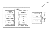
図14は、いくつかの実施形態による、例示的なUE110のブロック図である。UE110は、トランシーバ、プロセッサ、およびメモリのうちの1つまたは複数を含む。いくつかの実施形態では、トランシーバは、(たとえば、(1つまたは複数の)送信機(Tx)、(1つまたは複数の)受信機(Rx)および(1つまたは複数の)アンテナを介して)無線ネットワークノード120に無線信号を送信すること、および無線ネットワークノード120から無線信号を受信することを容易にする。プロセッサは、UE110によって与えられるかまたは実施されるものとして上記で説明された機能性の一部または全部を与えるための命令を実行し、メモリは、プロセッサによって実行される命令を記憶する。いくつかの実施形態では、プロセッサおよびメモリは、処理回路を形成する。
FIG. 14 is a block diagram of an
プロセッサは、上記で説明されたUE110の機能など、UE110の説明された機能の一部または全部を実施するために、命令を実行し、データを操作するための、ハードウェアの任意の好適な組合せを含み得る。いくつかの実施形態では、プロセッサは、たとえば、1つまたは複数のコンピュータ、1つまたは複数の中央処理ユニット(CPU)、1つまたは複数のマイクロプロセッサ、1つまたは複数の特定用途向け集積回路(ASIC)、1つまたは複数のフィールドプログラマブルゲートアレイ(FPGA)および/または他の論理を含み得る。
A processor is any suitable combination of hardware for executing instructions and manipulating data to implement some or all of the described functions of
メモリは、概して、コンピュータプログラム、ソフトウェア、論理、ルール、アルゴリズム、コード、テーブルなどのうちの1つまたは複数を含むアプリケーション、および/またはプロセッサによって実行されることが可能な他の命令など、命令を記憶するように動作可能である。メモリの例は、コンピュータメモリ(たとえば、ランダムアクセスメモリ(RAM)または読取り専用メモリ(ROM))、大容量記憶媒体(たとえば、ハードディスク)、リムーバブル記憶媒体(たとえば、コンパクトディスク(CD)またはデジタルビデオディスク(DVD))、ならびに/あるいは、UE110のプロセッサによって使用され得る情報、データ、および/または命令を記憶する、任意の他の揮発性または不揮発性、非一時的コンピュータ可読および/またはコンピュータ実行可能メモリデバイスを含む。
The memory generally stores instructions, such as computer programs, software, applications including one or more of logic, rules, algorithms, code, tables, etc., and/or other instructions capable of being executed by a processor. operable to store. Examples of memory are computer memory (e.g., random access memory (RAM) or read-only memory (ROM)), mass storage media (e.g., hard disks), removable storage media (e.g., compact discs (CDs) or digital video discs). (DVD)) and/or any other volatile or non-volatile, non-transitory computer-readable and/or computer-executable memory that stores information, data, and/or instructions that may be used by the processor of the
UE110の他の実施形態は、上記で説明された機能性および/または(上記で説明されたソリューションをサポートするのに必要な任意の機能性を含む)任意の追加の機能性のうちのいずれかを含む、UEの機能性のいくつかの態様を与えることを担当し得る、図14に示されている構成要素以外の追加の構成要素を含み得る。ほんの一例として、UE110は、プロセッサの一部であり得る、入力デバイスおよび回路、出力デバイス、ならびに1つまたは複数の同期ユニットまたは回路を含み得る。入力デバイスは、UE110へのデータのエントリのための機構を含む。たとえば、入力デバイスは、マイクロフォン、入力エレメント、ディスプレイなど、入力機構を含み得る。出力デバイスは、オーディオ、ビデオおよび/またはハードコピーフォーマットでデータを出力するための機構を含み得る。たとえば、出力デバイスは、スピーカー、ディスプレイなどを含み得る。
Other embodiments of
いくつかの実施形態では、UE110は、上記で説明されたUE110の機能性を実装するように設定された一連の機能モジュールを備え得る。図15を参照すると、いくつかの実施形態では、UE110は、無線ネットワークノードからダウンリンク送信を受信するように設定された受信モジュールであって、ダウンリンク送信が少なくとも1つの特性を有する、受信モジュールと、無線ネットワークノードへの今度のアップリンク送信のために2つまたはそれ以上の波形から1つの波形を選択するように設定された選択モジュールであって、波形が、ダウンリンク送信の少なくとも1つの特性に少なくとも部分的に基づいて選択される、選択モジュールと、選択された波形を使用して、無線ネットワークノードにアップリンク送信するように設定された送信モジュールとを備え得る。
In some embodiments,
様々なモジュールが、ハードウェアおよび/またはソフトウェア、たとえば、図14に示されているUE110のプロセッサ、メモリおよび(1つまたは複数の)トランシーバの組合せとして実装され得ることが諒解されよう。いくつかの実施形態は、追加のおよび/または随意の機能性をサポートするための追加のモジュールをも含み得る。
It will be appreciated that the various modules may be implemented as hardware and/or software, eg, a combination of processor, memory and transceiver(s) of
次に、無線ネットワークノード120の実施形態が、図16および図17に関して説明される。図16は、いくつかの実施形態による、例示的な無線ネットワークノード120のブロック図である。無線ネットワークノード120は、トランシーバ、プロセッサ、メモリ、および通信インターフェースのうちの1つまたは複数を含み得る。いくつかの実施形態では、トランシーバは、(たとえば、(1つまたは複数の)送信機(Tx)、(1つまたは複数の)受信機(Rx)、および(1つまたは複数の)アンテナを介して)UE110に無線信号を送信すること、およびUE110から無線信号を受信することを容易にする。プロセッサは、無線ネットワークノード120によって与えられるかまたは実施されるものとして上記で説明された機能性の一部または全部を与えるための命令を実行し、メモリは、プロセッサによって実行される命令を記憶する。いくつかの実施形態では、プロセッサおよびメモリは、処理回路を形成する。通信インターフェースは、無線ネットワークノード120が、ゲートウェイ、スイッチ、ルータ、インターネット、公衆交換電話網(PSTN)、コアネットワークノードまたは無線ネットワークコントローラなど、バックエンドネットワーク構成要素に信号を通信することを可能にするためなどの、コアネットワークインターフェースおよび無線ネットワークインターフェースを備え得る。
Embodiments of the
プロセッサは、命令を実行し、上記で説明された機能など、無線ネットワークノード120の説明された機能の一部または全部を実施するようにデータを操作するための、ハードウェアの任意の好適な組合せを含み得る。いくつかの実施形態では、プロセッサは、たとえば、1つまたは複数のコンピュータ、1つまたは複数の中央処理ユニット(CPU)、1つまたは複数のマイクロプロセッサ、1つまたは複数の特定用途向け集積回路(ASIC)、1つまたは複数のフィールドプログラマブルゲートアレイ(FPGA)および/または他の論理を含み得る。
The processor is any suitable combination of hardware for executing instructions and manipulating data to implement some or all of the described functions of the
メモリは、概して、コンピュータプログラム、ソフトウェア、論理、ルール、アルゴリズム、コード、テーブルなどのうちの1つまたは複数を含むアプリケーション、および/またはプロセッサによって実行されることが可能な他の命令など、命令を記憶するように動作可能である。メモリの例は、コンピュータメモリ(たとえば、ランダムアクセスメモリ(RAM)または読取り専用メモリ(ROM))、大容量記憶媒体(たとえば、ハードディスク)、リムーバブル記憶媒体(たとえば、コンパクトディスク(CD)またはデジタルビデオディスク(DVD))、ならびに/あるいは情報を記憶する任意の他の揮発性または不揮発性、非一時的コンピュータ可読および/またはコンピュータ実行可能メモリデバイスを含む。 The memory generally stores instructions, such as computer programs, software, applications including one or more of logic, rules, algorithms, code, tables, etc., and/or other instructions capable of being executed by a processor. operable to store. Examples of memory are computer memory (e.g., random access memory (RAM) or read-only memory (ROM)), mass storage media (e.g., hard disks), removable storage media (e.g., compact discs (CDs) or digital video discs). (DVD)), and/or any other volatile or non-volatile, non-transitory computer-readable and/or computer-executable memory device for storing information.
いくつかの実施形態では、通信インターフェースは、プロセッサに通信可能に結合され、無線ネットワークノード120のための入力を受信するか、無線ネットワークノード120からの出力を送るか、入力または出力またはその両方の好適な処理を実施するか、他のデバイスに通信するか、あるいは前述の任意の組合せを行うように動作可能な任意の好適なデバイスを指し得る。通信インターフェースは、ネットワークを通して通信するために、適切なハードウェア(たとえば、ポート、モデム、ネットワークインターフェースカードなど)と、プロトコル変換能力およびデータ処理能力を含むソフトウェアとを含み得る。
In some embodiments, a communication interface is communicatively coupled to the processor to receive input for the
無線ネットワークノード120の他の実施形態は、上記で説明された機能性および/または(上記で説明されたソリューションをサポートするのに必要な任意の機能性を含む)任意の追加の機能性のうちのいずれかを含む、無線ネットワークノードの機能性のいくつかの態様を与えることを担当し得る、図16に示されている構成要素以外の追加の構成要素を含み得る。様々な異なるタイプのネットワークノードは、同じ物理ハードウェアを有するが(たとえば、プログラミングを介して)異なる無線アクセス技術をサポートするように設定された構成要素を含み得るか、あるいは部分的にまたは完全に異なる物理構成要素を表し得る。
Other embodiments of
いくつかの実施形態では、無線ネットワークノード120は、上記で説明された無線ネットワークノード120の機能性を実装するように設定された一連のモジュールを備え得る。図17を参照すると、いくつかの実施形態では、無線ネットワークノード120は、ユーザ機器にダウンリンク送信を送信するように設定された送信モジュールであって、ダウンリンク送信が少なくとも1つの特性を有する、送信モジュールと、ユーザ機器からアップリンク送信を受信するように設定された受信モジュールであって、アップリンク送信が、ダウンリンク送信の少なくとも1つの特性に少なくとも部分的に基づいて2つまたはそれ以上の波形から選択された波形を使用する、受信モジュールとを備え得る。
In some embodiments, the
様々なモジュールが、ハードウェアおよび/またはソフトウェア、たとえば、図16に示されている無線ネットワークノード120のプロセッサ、メモリおよび(1つまたは複数の)トランシーバの組合せとして実装され得ることが諒解されよう。いくつかの実施形態は、追加のおよび/または随意の機能性をサポートするための追加のモジュールをも含み得る。
It will be appreciated that the various modules may be implemented as hardware and/or software, eg, a combination of processor, memory and transceiver(s) of
いくつかの実施形態は、機械可読媒体(媒体において具現化されたコンピュータ可読プログラムコードを有する、コンピュータ可読媒体、プロセッサ可読媒体、またはコンピュータ使用可能媒体とも呼ばれる)に記憶された非一時的ソフトウェア製品として表され得る。機械可読媒体は、ディスケット、コンパクトディスク読取り専用メモリ(CD-ROM)、デジタル多用途ディスク読取り専用メモリ(DVD-ROM)メモリデバイス(揮発性または不揮発性)、または同様の記憶機構を含む、磁気、光、または電気的記憶媒体を含む任意の好適な有形媒体であり得る。機械可読媒体は、実行されたとき、プロセッサに、説明された実施形態のうちの1つまたは複数による方法におけるステップを実施させる、命令、コードシーケンス、設定情報、または他のデータの様々なセットを含んでいることがある。当業者は、説明された実施形態を実装するのに必要な他の命令および動作も、機械可読媒体に記憶され得ることを諒解されよう。機械可読媒体から動作するソフトウェアは、説明されたタスクを実施するために回路とインターフェースし得る。 Some embodiments are described as a non-transitory software product stored on machine-readable media (also called computer-readable media, processor-readable media, or computer-usable media having computer-readable program code embodied in the media). can be represented. Machine-readable media include diskettes, compact disc read-only memory (CD-ROM), digital versatile disc read-only memory (DVD-ROM) memory devices (volatile or nonvolatile), or similar storage mechanisms, magnetic, It can be any suitable tangible medium, including optical or electrical storage media. Machine-readable media carry various sets of instructions, code sequences, configuration information, or other data that, when executed, cause a processor to perform steps in a method in accordance with one or more of the described embodiments. It may contain Those skilled in the art will appreciate that other instructions and acts required to implement the described embodiments can also be stored on the machine-readable medium. Software running from a machine-readable medium may interface with the circuits to perform the tasks described.
上記で説明された実施形態は、例にすぎないことを意図する。その説明の範囲から逸脱することなく、当業者によって特定の実施形態の改変、修正および変形が実現され得る。 The embodiments described above are intended to be examples only. Variations, modifications and variations of the specific embodiments may be effected by those skilled in the art without departing from the scope of the description.
略語
本明細書は、以下の略語のうちの1つまたは複数を含み得る。
Abbreviations This specification may contain one or more of the following abbreviations.
CDM 符号分割多重 CDM code division multiplexing
CQI チャネル品質情報 CQI channel quality information
CRC サイクリック冗長検査 CRC cyclic redundancy check
DCI ダウンリンク制御情報 DCI downlink control information
DFT 離散フーリエ変換 DFT Discrete Fourier Transform
DM-RS 復調用参照信号 DM-RS Demodulation reference signal
FBMC フィルタバンクマルチキャリア FBMC filter bank multi-carrier
FDM 周波数分割多重 FDM frequency division multiplexing
HARQ ハイブリッド自動再送要求 HARQ Hybrid Automatic Repeat Request
OFDM 直交周波数分割多重 OFDM Orthogonal Frequency Division Multiplexing
PAPR ピーク対平均電力比 PAPR peak-to-average power ratio
PDCCH 物理ダウンリンク制御チャネル PDCCH Physical Downlink Control Channel
PUCCH 物理アップリンク制御チャネル PUCCH Physical Uplink Control Channel
PUSCH 物理アップリンク共有チャネル PUSCH Physical Uplink Shared Channel
PRB 物理リソースブロック PRB physical resource block
RRC 無線リソース制御 RRC radio resource control
UCI アップリンク制御情報 UCI uplink control information
Claims (18)
無線ネットワークノードからダウンリンク制御メッセージを受信することであって、前記ダウンリンク制御メッセージがフォーマットを有し、無線ネットワーク一時識別子(RNTI)を使用してスクランブルされた、ダウンリンク制御メッセージを受信することと、
前記無線ネットワークノードへの今度のアップリンク送信のために2つまたはそれ以上の波形から1つの波形を選択することであって、前記波形が、前記ダウンリンク制御メッセージの前記フォーマットと、前記ダウンリンク制御メッセージをスクランブルするために使用された前記RNTIと、前記UEの無線リソース制御(RRC)設定と、に少なくとも部分的に基づいて選択される、1つの波形を選択することと、
前記選択された波形を使用して、前記無線ネットワークノードに前記アップリンク送信を送信することと、
システム情報から第1の波形を決定することと、
前記UEの前記RRC設定から第2の波形を決定することと、を含み、
2つまたはそれ以上の波形から1つの波形を選択することが、前記無線ネットワークノードへの今度のアップリンク送信のために前記第1の波形および前記第2の波形から1つの波形を選択することをさらに含み、前記波形が、前記ダウンリンク制御メッセージの前記フォーマットと、前記ダウンリンク制御メッセージをスクランブルするために使用された前記RNTIと、前記UEの前記RRC設定と、に少なくとも部分的に基づいて選択され、
前記選択された波形を使用して、前記無線ネットワークノードに前記アップリンク送信を送信することをさらに含む、
方法。 A method in a user equipment (UE), the method comprising:
Receiving a downlink control message from a radio network node, said downlink control message having a format and being scrambled using a Radio Network Temporary Identifier (RNTI). When,
selecting one waveform from two or more waveforms for an upcoming uplink transmission to the radio network node, wherein the waveform corresponds to the format of the downlink control message and the downlink selecting one waveform, selected based at least in part on the RNTI used to scramble control messages and a Radio Resource Control (RRC) setting of the UE;
transmitting the uplink transmission to the radio network node using the selected waveform ;
determining a first waveform from system information;
determining a second waveform from the RRC configuration of the UE;
selecting one waveform from two or more waveforms, selecting one waveform from said first waveform and said second waveform for an upcoming uplink transmission to said radio network node; wherein the waveform is based at least in part on the format of the downlink control message, the RNTI used to scramble the downlink control message, and the RRC configuration of the UE. selected,
further comprising transmitting the uplink transmission to the radio network node using the selected waveform;
Method.
無線ネットワークノードからダウンリンク制御メッセージを受信することであって、前記ダウンリンク制御メッセージがフォーマットを有し、無線ネットワーク一時識別子(RNTI)を使用してスクランブルされた、ダウンリンク制御メッセージを受信することと、
前記無線ネットワークノードへの今度のアップリンク送信のために2つまたはそれ以上の波形から1つの波形を選択することであって、前記波形が、前記ダウンリンク制御メッセージの前記フォーマットと、前記ダウンリンク制御メッセージをスクランブルするために使用された前記RNTIと、前記UEの無線リソース制御(RRC)設定と、に少なくとも部分的に基づいて選択される、1つの波形を選択することと、
前記選択された波形を使用して、前記無線ネットワークノードに前記アップリンク送信を送信することと
を行うように適合された処理回路を備え、
前記処理回路は、
システム情報から第1の波形を決定することと、
前記UEの前記RRC設定から第2の波形を決定することと、
を行うようにさらに適合されていて、
2つまたはそれ以上の波形から1つの波形を選択することが、前記無線ネットワークノードへの今度のアップリンク送信のために前記第1の波形および前記第2の波形から1つの波形を選択することをさらに含み、前記波形が、前記ダウンリンク制御メッセージの前記フォーマットと、前記ダウンリンク制御メッセージをスクランブルするために使用された前記RNTIと、前記UEの前記RRC設定と、に少なくとも部分的に基づいて選択され、
前記選択された波形を使用して、前記無線ネットワークノードに前記アップリンク送信を送信することをさらに含む、
ユーザ機器(UE)。 A user equipment (UE),
Receiving a downlink control message from a radio network node, said downlink control message having a format and being scrambled using a Radio Network Temporary Identifier (RNTI). When,
selecting one waveform from two or more waveforms for an upcoming uplink transmission to the radio network node, wherein the waveform corresponds to the format of the downlink control message and the downlink selecting one waveform, selected based at least in part on the RNTI used to scramble control messages and a Radio Resource Control (RRC) setting of the UE;
transmitting said uplink transmission to said radio network node using said selected waveform ;
The processing circuit is
determining a first waveform from system information;
determining a second waveform from the RRC configuration of the UE;
is further adapted to perform
selecting one waveform from two or more waveforms, selecting one waveform from said first waveform and said second waveform for an upcoming uplink transmission to said radio network node; wherein the waveform is based at least in part on the format of the downlink control message, the RNTI used to scramble the downlink control message, and the RRC configuration of the UE. selected,
further comprising transmitting the uplink transmission to the radio network node using the selected waveform;
User Equipment (UE).
無線ネットワークノードからダウンリンク制御メッセージを受信するためのコンピュータ可読プログラムコードであって、前記ダウンリンク制御メッセージがフォーマットを有し、無線ネットワーク一時識別子(RNTI)を使用してスクランブルされた、ダウンリンク制御メッセージを受信するためのコンピュータ可読プログラムコードと、
前記無線ネットワークノードへの今度のアップリンク送信のために2つまたはそれ以上の波形から1つの波形を選択するためのコンピュータ可読プログラムコードであって、前記波形が、前記ダウンリンク制御メッセージの前記フォーマットと、前記ダウンリンク制御メッセージをスクランブルするために使用された前記RNTIと、ユーザ機器(UE)の無線リソース制御(RRC)設定と、に少なくとも部分的に基づいて選択される、コンピュータ可読プログラムコードと、
前記選択された波形を使用して、前記無線ネットワークノードに前記アップリンク送信を送信するためのコンピュータ可読プログラムコードと、
システム情報から第1の波形を決定するためのコンピュータ可読プログラムコードと、
前記UEの前記RRC設定から第2の波形を決定するためのコンピュータ可読プログラムコードと、を備え、
2つまたはそれ以上の波形から1つの波形を選択することが、前記無線ネットワークノードへの今度のアップリンク送信のために前記第1の波形および前記第2の波形から1つの波形を選択することをさらに含み、前記波形が、前記ダウンリンク制御メッセージの前記フォーマットと、前記ダウンリンク制御メッセージをスクランブルするために使用された前記RNTIと、前記UEの前記RRC設定と、に少なくとも部分的に基づいて選択され、
前記選択された波形を使用して、前記無線ネットワークノードに前記アップリンク送信を送信するためのコンピュータ可読プログラムコードをさらに含む、
コンピュータプログラム。 A computer program,
Computer readable program code for receiving a downlink control message from a radio network node, said downlink control message having a format and scrambled using a Radio Network Temporary Identifier (RNTI). computer readable program code for receiving a message;
computer readable program code for selecting one waveform from two or more waveforms for an upcoming uplink transmission to said radio network node, said waveform corresponding to said format of said downlink control message; and computer readable program code selected based at least in part on the RNTI used to scramble the downlink control message and a radio resource control (RRC) setting of a user equipment (UE). ,
computer readable program code for transmitting the uplink transmission to the wireless network node using the selected waveform ;
computer readable program code for determining a first waveform from system information;
computer readable program code for determining a second waveform from the RRC settings of the UE;
selecting one waveform from two or more waveforms, selecting one waveform from said first waveform and said second waveform for an upcoming uplink transmission to said radio network node; wherein the waveform is based at least in part on the format of the downlink control message, the RNTI used to scramble the downlink control message, and the RRC configuration of the UE. selected,
further comprising computer readable program code for transmitting said uplink transmission to said wireless network node using said selected waveform;
computer program.
ユーザ機器(UE)にダウンリンク制御メッセージを送信することであって、前記ダウンリンク制御メッセージがフォーマットを有し、無線ネットワーク一時識別子(RNTI)を使用してスクランブルされた、ダウンリンク制御メッセージを送信することと、
前記ユーザ機器からアップリンク送信を受信することであって、前記アップリンク送信が、前記ダウンリンク制御メッセージの前記フォーマットと、前記ダウンリンク制御メッセージをスクランブルするために使用された前記RNTIと、前記UEの無線リソース制御(RRC)設定と、に少なくとも部分的に基づいて2つまたはそれ以上の波形から選択された波形を使用する、アップリンク送信を受信することと
を含み、
2つまたはそれ以上の波形は、
システム情報から決定された第1の波形と、前記UEの前記RRC設定から決定された第2の波形とを含む、
方法。 A method in a radio network node, the method comprising:
transmitting a downlink control message to a user equipment (UE), said downlink control message having a format and scrambled using a Radio Network Temporary Identifier (RNTI). and
receiving an uplink transmission from the user equipment, the uplink transmission comprising the format of the downlink control message, the RNTI used to scramble the downlink control message, and the UE. receiving an uplink transmission using a waveform selected from the two or more waveforms based at least in part on a radio resource control (RRC) setting of
Two or more waveforms are
a first waveform determined from system information and a second waveform determined from the RRC configuration of the UE;
Method.
ユーザ機器(UE)にダウンリンク制御メッセージを送信することであって、前記ダウンリンク制御メッセージがフォーマットを有し、無線ネットワーク一時識別子(RNTI)を使用してスクランブルされた、ダウンリンク制御メッセージを送信することと、
前記ユーザ機器からアップリンク送信を受信することであって、前記アップリンク送信が、前記ダウンリンク制御メッセージの前記フォーマットと、前記ダウンリンク制御メッセージをスクランブルするために使用された前記RNTIと、前記UEの無線リソース制御(RRC)設定と、に少なくとも部分的に基づいて2つまたはそれ以上の波形から選択された波形を使用する、アップリンク送信を受信することと
を行うように適合された処理回路を備え、
2つまたはそれ以上の波形は、
システム情報から決定された第1の波形と、前記UEの前記RRC設定から決定された第2の波形とを含む、
無線ネットワークノード。 A radio network node,
transmitting a downlink control message to a user equipment (UE), said downlink control message having a format and scrambled using a Radio Network Temporary Identifier (RNTI). and
receiving an uplink transmission from the user equipment, the uplink transmission comprising the format of the downlink control message, the RNTI used to scramble the downlink control message, and the UE. and receiving an uplink transmission using a waveform selected from two or more waveforms based at least in part on a radio resource control (RRC) setting of with
Two or more waveforms are
a first waveform determined from system information and a second waveform determined from the RRC configuration of the UE;
radio network node.
前記ユーザ機器からアップリンク送信を受信するためのコンピュータ可読プログラムコードであって、前記アップリンク送信が、前記ダウンリンク制御メッセージの前記フォーマットと、前記ダウンリンク制御メッセージをスクランブルするために使用されたRNTIと、前記UEの無線リソース制御(RRC)設定と、に少なくとも部分的に基づいて2つまたはそれ以上の波形から選択された波形を使用する、コンピュータ可読プログラムコードと
を備え、
2つまたはそれ以上の波形は、
システム情報から決定された第1の波形と、前記UEの前記RRC設定から決定された第2の波形とを含む、
コンピュータプログラム。 Computer readable program code for transmitting a downlink control message to a user equipment (UE), said downlink control message formatted and scrambled using a Radio Network Temporary Identifier (RNTI). computer readable program code for sending a message;
computer readable program code for receiving an uplink transmission from said user equipment, said uplink transmission said format of said downlink control message and an RNTI used to scramble said downlink control message and computer readable program code using a waveform selected from two or more waveforms based at least in part on radio resource control (RRC) settings of the UE ;
Two or more waveforms are
a first waveform determined from system information and a second waveform determined from the RRC configuration of the UE;
computer program.
Applications Claiming Priority (3)
| Application Number | Priority Date | Filing Date | Title |
|---|---|---|---|
| US201762521157P | 2017-06-16 | 2017-06-16 | |
| US62/521,157 | 2017-06-16 | ||
| PCT/IB2018/054478 WO2018229736A1 (en) | 2017-06-16 | 2018-06-18 | Waveform indication in wireless communication networks |
Publications (2)
| Publication Number | Publication Date |
|---|---|
| JP2020523941A JP2020523941A (en) | 2020-08-06 |
| JP7150758B2 true JP7150758B2 (en) | 2022-10-11 |
Family
ID=62981281
Family Applications (1)
| Application Number | Title | Priority Date | Filing Date |
|---|---|---|---|
| JP2019569792A Active JP7150758B2 (en) | 2017-06-16 | 2018-06-18 | Waveform indication in wireless communication network |
Country Status (10)
| Country | Link |
|---|---|
| US (1) | US11451357B2 (en) |
| EP (1) | EP3639494A1 (en) |
| JP (1) | JP7150758B2 (en) |
| KR (1) | KR102342174B1 (en) |
| CN (1) | CN110999245B (en) |
| CO (1) | CO2019014824A2 (en) |
| MX (1) | MX2019015113A (en) |
| RU (1) | RU2734860C1 (en) |
| SG (1) | SG11201912136VA (en) |
| WO (1) | WO2018229736A1 (en) |
Families Citing this family (10)
| Publication number | Priority date | Publication date | Assignee | Title |
|---|---|---|---|---|
| US10856280B2 (en) * | 2017-03-15 | 2020-12-01 | Samsung Electronics Co., Ltd. | Method and apparatus for downlink control information design for network coordination |
| EP3616459B1 (en) * | 2017-04-24 | 2022-06-08 | Telefonaktiebolaget LM Ericsson (publ) | Transmission profiles for nr |
| US11564203B2 (en) * | 2017-08-18 | 2023-01-24 | Ntt Docomo, Inc. | User terminal and radio communication method |
| EP4029173A1 (en) * | 2019-09-09 | 2022-07-20 | Telefonaktiebolaget LM Ericsson (publ) | Switching waveforms for uplink transmission in nr network |
| US11658766B2 (en) * | 2020-10-15 | 2023-05-23 | Qualcomm Incorporated | Techniques for indicating a waveform configuration |
| US11924014B2 (en) | 2020-10-15 | 2024-03-05 | Qualcomm Incorporated | Dynamic modulation and coding scheme table switching to indicate transmit waveform switching |
| US11800380B1 (en) | 2021-06-21 | 2023-10-24 | T-Mobile Innovations Llc | Flexible uplink waveform selection |
| CN113434511B (en) * | 2021-07-12 | 2023-08-29 | 北京林业大学 | Clustering index method based on Hilbert curve |
| CN116709528A (en) * | 2022-02-24 | 2023-09-05 | 上海朗帛通信技术有限公司 | Method and apparatus in a node for wireless communication |
| FI130701B1 (en) * | 2022-09-29 | 2024-01-25 | Nokia Technologies Oy | Determining waveform for uplink transmission |
Citations (7)
| Publication number | Priority date | Publication date | Assignee | Title |
|---|---|---|---|---|
| US20100034152A1 (en) | 2008-08-11 | 2010-02-11 | Sharp Laboratories Of America, Inc. | Systems and methods for ofdma and sc-fdma switching |
| JP2011223111A (en) | 2010-04-05 | 2011-11-04 | Ntt Docomo Inc | Wireless communication control device and wireless communication control method |
| JP2013507843A (en) | 2009-10-08 | 2013-03-04 | クゥアルコム・インコーポレイテッド | Downlink control information for efficient decoding |
| US20150341915A1 (en) | 2013-02-05 | 2015-11-26 | Huawei Technologies Co., Ltd. | Carrier indication method, user equipment, and base station |
| WO2016171765A1 (en) | 2015-04-22 | 2016-10-27 | Intel IP Corporation | Transmission designs for radio access technologies |
| WO2018112758A1 (en) | 2016-12-20 | 2018-06-28 | 广东欧珀移动通信有限公司 | Method and device for configuring communication parameter |
| WO2018127202A1 (en) | 2017-01-09 | 2018-07-12 | 华为技术有限公司 | Method and device for transmitting a reference signal |
Family Cites Families (17)
| Publication number | Priority date | Publication date | Assignee | Title |
|---|---|---|---|---|
| DK1949721T3 (en) | 2005-10-07 | 2010-10-25 | Interdigital Tech Corp | Communication of control information for downlink and uplink transmissions in a wireless communication system |
| DE602008054404C5 (en) * | 2007-06-12 | 2024-04-11 | MiiCs & Partners Japan Co., Ltd. | Base station, mobile station, and method for requesting uplink synchronization. |
| US9344259B2 (en) * | 2007-06-20 | 2016-05-17 | Google Technology Holdings LLC | Control channel provisioning and signaling |
| US8169992B2 (en) * | 2007-08-08 | 2012-05-01 | Telefonaktiebolaget Lm Ericsson (Publ) | Uplink scrambling during random access |
| US9137806B2 (en) | 2007-09-21 | 2015-09-15 | Qualcomm Incorporated | Interference management employing fractional time reuse |
| EP2464030B1 (en) * | 2009-08-06 | 2019-01-09 | LG Electronics Inc. | Method and apparatus for transmitting uplink signals in wireless communication system for supporting multiple antenna transmission |
| CN101772179A (en) * | 2010-01-08 | 2010-07-07 | 中兴通讯股份有限公司 | Method and system for transmitting system information in carrier aggregation scene |
| US8902830B2 (en) * | 2010-12-28 | 2014-12-02 | Motorola Mobility Llc | Energy-saving base station and method |
| EP2501057A1 (en) * | 2011-03-17 | 2012-09-19 | Panasonic Corporation | Dynamic PUSCH deactivation/activation for component carriers of a relay node |
| JP5325928B2 (en) | 2011-05-02 | 2013-10-23 | 株式会社エヌ・ティ・ティ・ドコモ | Channel state information notification method, radio base station apparatus, user terminal, and radio communication system |
| CN105264996B (en) * | 2013-07-01 | 2020-03-10 | 华为技术有限公司 | Carrier state indication method and device |
| US9930699B2 (en) * | 2013-10-31 | 2018-03-27 | Telefonaktiebolaget Lm Ericsson (Publ) | Providing access control parameters to a user equipment |
| US9787515B2 (en) * | 2014-02-13 | 2017-10-10 | Huawei Technologies Co., Ltd. | System and method for guard band utilization for synchronous and asynchronous communications |
| CN106559890B (en) * | 2015-09-29 | 2021-08-31 | 华为技术有限公司 | Method and device for transmitting control signaling |
| US10425973B2 (en) * | 2015-11-25 | 2019-09-24 | Qualcomm Incorporated | Random access channel signaling on a shared communication medium |
| US10536946B2 (en) | 2015-12-08 | 2020-01-14 | Huawei Technologies Co., Ltd. | Method and system for performing network slicing in a radio access network |
| US10419086B2 (en) * | 2016-04-26 | 2019-09-17 | Samsung Electronics Co., Ltd. | Method and apparatus for enabling uplink MIMO |
-
2018
- 2018-06-18 MX MX2019015113A patent/MX2019015113A/en unknown
- 2018-06-18 CN CN201880052330.1A patent/CN110999245B/en active Active
- 2018-06-18 KR KR1020207000760A patent/KR102342174B1/en active IP Right Grant
- 2018-06-18 EP EP18743589.6A patent/EP3639494A1/en active Pending
- 2018-06-18 RU RU2020101232A patent/RU2734860C1/en active
- 2018-06-18 SG SG11201912136VA patent/SG11201912136VA/en unknown
- 2018-06-18 JP JP2019569792A patent/JP7150758B2/en active Active
- 2018-06-18 WO PCT/IB2018/054478 patent/WO2018229736A1/en active Application Filing
- 2018-06-18 US US16/621,922 patent/US11451357B2/en active Active
-
2019
- 2019-12-27 CO CONC2019/0014824A patent/CO2019014824A2/en unknown
Patent Citations (8)
| Publication number | Priority date | Publication date | Assignee | Title |
|---|---|---|---|---|
| US20100034152A1 (en) | 2008-08-11 | 2010-02-11 | Sharp Laboratories Of America, Inc. | Systems and methods for ofdma and sc-fdma switching |
| JP2011530837A (en) | 2008-08-11 | 2011-12-22 | シャープ株式会社 | Switching system and method for switching between OFDMA and C-FDMA |
| JP2013507843A (en) | 2009-10-08 | 2013-03-04 | クゥアルコム・インコーポレイテッド | Downlink control information for efficient decoding |
| JP2011223111A (en) | 2010-04-05 | 2011-11-04 | Ntt Docomo Inc | Wireless communication control device and wireless communication control method |
| US20150341915A1 (en) | 2013-02-05 | 2015-11-26 | Huawei Technologies Co., Ltd. | Carrier indication method, user equipment, and base station |
| WO2016171765A1 (en) | 2015-04-22 | 2016-10-27 | Intel IP Corporation | Transmission designs for radio access technologies |
| WO2018112758A1 (en) | 2016-12-20 | 2018-06-28 | 广东欧珀移动通信有限公司 | Method and device for configuring communication parameter |
| WO2018127202A1 (en) | 2017-01-09 | 2018-07-12 | 华为技术有限公司 | Method and device for transmitting a reference signal |
Also Published As
| Publication number | Publication date |
|---|---|
| SG11201912136VA (en) | 2020-01-30 |
| CN110999245A (en) | 2020-04-10 |
| CN110999245B (en) | 2022-09-23 |
| JP2020523941A (en) | 2020-08-06 |
| US11451357B2 (en) | 2022-09-20 |
| KR20200008175A (en) | 2020-01-23 |
| MX2019015113A (en) | 2020-02-07 |
| CO2019014824A2 (en) | 2020-01-17 |
| KR102342174B1 (en) | 2021-12-22 |
| WO2018229736A1 (en) | 2018-12-20 |
| US20200127787A1 (en) | 2020-04-23 |
| RU2734860C1 (en) | 2020-10-23 |
| EP3639494A1 (en) | 2020-04-22 |
Similar Documents
| Publication | Publication Date | Title |
|---|---|---|
| JP7150758B2 (en) | Waveform indication in wireless communication network | |
| US10841904B2 (en) | Short physical uplink control channel (PUCCH) design for 5th generation (5G) new radio (NR) | |
| AU2018313837B2 (en) | Multiple slot long physical uplink control channel (PUCCH) design for 5th generation (5G) new radio (NR) | |
| US10455560B2 (en) | Short physical uplink control channel (PUCCH) design for 5th generation (5G) new radio (NR) | |
| KR102014629B1 (en) | Short PUCCH (SPUCCH) on the uplink | |
| JP6723388B2 (en) | Base station device, terminal device and communication method thereof | |
| US11039429B2 (en) | Method and apparatus for downlink control information communication and interpretation | |
| US11089582B2 (en) | Method and system for downlink control information payload size determination | |
| AU2018216827B2 (en) | Short physical uplink control channel (PUCCH) design for 5th generation (5G) new radio (NR) | |
| JP6163554B2 (en) | Terminal apparatus, base station apparatus, and communication method | |
| WO2019032741A1 (en) | SLOT STRUCTURE OF LONG PHYSICAL UPLINK CONTROL CHANNEL (PUCCH) DESIGN FOR 5th GENERATION (5G) NEW RADIO (NR) | |
| EP3316615B1 (en) | Terminal device, base station, communication method, and integrated circuit | |
| EP3566371B1 (en) | Short physical uplink control channel (pucch) design for 5th generation (5g) new radio (nr) | |
| CN104335652B (en) | User terminal, wireless communications method and wireless communication system | |
| KR20140040741A (en) | Method and device for information transmission in wireless communication system | |
| EP3291624A1 (en) | Terminal device, base station device, communication method, and integrated circuit | |
| EP3291623A1 (en) | Terminal device, base station device, communication method, and integrated circuit | |
| US11943763B2 (en) | Method and apparatus for distributed resource allocation in a wireless communication system | |
| WO2019099738A1 (en) | User equipments, base stations and methods | |
| AU2018284829A1 (en) | Base station apparatus, terminal apparatus, and communication method for the same | |
| WO2022186230A1 (en) | Terminal device and base station device | |
| US20240097959A1 (en) | Waveform indication in wireless communication networks | |
| WO2019167785A1 (en) | Communication device and communication method | |
| OA18894A (en) | User terminal, wireless base station, and wireless communication method |
Legal Events
| Date | Code | Title | Description |
|---|---|---|---|
| A529 | Written submission of copy of amendment under article 34 pct |
Free format text: JAPANESE INTERMEDIATE CODE: A529 Effective date: 20200203 |
|
| A621 | Written request for application examination |
Free format text: JAPANESE INTERMEDIATE CODE: A621 Effective date: 20200204 |
|
| A977 | Report on retrieval |
Free format text: JAPANESE INTERMEDIATE CODE: A971007 Effective date: 20210315 |
|
| A131 | Notification of reasons for refusal |
Free format text: JAPANESE INTERMEDIATE CODE: A131 Effective date: 20210511 |
|
| A521 | Request for written amendment filed |
Free format text: JAPANESE INTERMEDIATE CODE: A523 Effective date: 20210802 |
|
| A131 | Notification of reasons for refusal |
Free format text: JAPANESE INTERMEDIATE CODE: A131 Effective date: 20220118 |
|
| A521 | Request for written amendment filed |
Free format text: JAPANESE INTERMEDIATE CODE: A523 Effective date: 20220407 |
|
| TRDD | Decision of grant or rejection written | ||
| A01 | Written decision to grant a patent or to grant a registration (utility model) |
Free format text: JAPANESE INTERMEDIATE CODE: A01 Effective date: 20220830 |
|
| A61 | First payment of annual fees (during grant procedure) |
Free format text: JAPANESE INTERMEDIATE CODE: A61 Effective date: 20220928 |
|
| R150 | Certificate of patent or registration of utility model |
Ref document number: 7150758 Country of ref document: JP Free format text: JAPANESE INTERMEDIATE CODE: R150 |