WO2020022421A1 - Photoelectric conversion element - Google Patents
Photoelectric conversion element Download PDFInfo
- Publication number
- WO2020022421A1 WO2020022421A1 PCT/JP2019/029184 JP2019029184W WO2020022421A1 WO 2020022421 A1 WO2020022421 A1 WO 2020022421A1 JP 2019029184 W JP2019029184 W JP 2019029184W WO 2020022421 A1 WO2020022421 A1 WO 2020022421A1
- Authority
- WO
- WIPO (PCT)
- Prior art keywords
- organic semiconductor
- semiconductor material
- photoelectric conversion
- conversion layer
- organic
- Prior art date
Links
- 238000006243 chemical reaction Methods 0.000 title claims abstract description 398
- 239000000463 material Substances 0.000 claims abstract description 776
- 239000004065 semiconductor Substances 0.000 claims abstract description 696
- 238000004768 lowest unoccupied molecular orbital Methods 0.000 claims abstract description 71
- 238000004770 highest occupied molecular orbital Methods 0.000 claims abstract description 67
- XMWRBQBLMFGWIX-UHFFFAOYSA-N C60 fullerene Chemical compound C12=C3C(C4=C56)=C7C8=C5C5=C9C%10=C6C6=C4C1=C1C4=C6C6=C%10C%10=C9C9=C%11C5=C8C5=C8C7=C3C3=C7C2=C1C1=C2C4=C6C4=C%10C6=C9C9=C%11C5=C5C8=C3C3=C7C1=C1C2=C4C6=C2C9=C5C3=C12 XMWRBQBLMFGWIX-UHFFFAOYSA-N 0.000 claims description 73
- 229910003472 fullerene Inorganic materials 0.000 claims description 48
- 239000000539 dimer Substances 0.000 claims description 21
- 230000005484 gravity Effects 0.000 claims description 21
- 239000013078 crystal Substances 0.000 claims description 19
- 238000004402 ultra-violet photoelectron spectroscopy Methods 0.000 claims description 18
- 238000010521 absorption reaction Methods 0.000 claims description 17
- 238000000103 photoluminescence spectrum Methods 0.000 claims description 16
- 239000000203 mixture Substances 0.000 claims description 15
- 238000002361 inverse photoelectron spectroscopy Methods 0.000 claims description 13
- 238000003077 quantum chemistry computational method Methods 0.000 claims description 4
- 239000010410 layer Substances 0.000 description 237
- 238000003384 imaging method Methods 0.000 description 97
- 239000000975 dye Substances 0.000 description 90
- 238000004891 communication Methods 0.000 description 73
- 239000000758 substrate Substances 0.000 description 51
- 230000006870 function Effects 0.000 description 48
- 238000001514 detection method Methods 0.000 description 45
- 238000012545 processing Methods 0.000 description 42
- 238000000034 method Methods 0.000 description 35
- 238000005259 measurement Methods 0.000 description 29
- BBEAQIROQSPTKN-UHFFFAOYSA-N pyrene Chemical compound C1=CC=C2C=CC3=CC=CC4=CC=C1C2=C43 BBEAQIROQSPTKN-UHFFFAOYSA-N 0.000 description 28
- 238000005516 engineering process Methods 0.000 description 27
- 230000003287 optical effect Effects 0.000 description 27
- GVEPBJHOBDJJJI-UHFFFAOYSA-N fluoranthrene Natural products C1=CC(C2=CC=CC=C22)=C3C2=CC=CC3=C1 GVEPBJHOBDJJJI-UHFFFAOYSA-N 0.000 description 24
- 238000004220 aggregation Methods 0.000 description 20
- 239000011368 organic material Substances 0.000 description 19
- 238000012546 transfer Methods 0.000 description 19
- MWPLVEDNUUSJAV-UHFFFAOYSA-N anthracene Chemical compound C1=CC=CC2=CC3=CC=CC=C3C=C21 MWPLVEDNUUSJAV-UHFFFAOYSA-N 0.000 description 18
- 238000010586 diagram Methods 0.000 description 18
- 238000009826 distribution Methods 0.000 description 16
- 230000000630 rising effect Effects 0.000 description 16
- 125000003118 aryl group Chemical group 0.000 description 15
- -1 boron chlorinated subphthalocyanine Chemical class 0.000 description 15
- 238000004364 calculation method Methods 0.000 description 15
- 229910052751 metal Inorganic materials 0.000 description 15
- 239000002184 metal Substances 0.000 description 15
- 230000007423 decrease Effects 0.000 description 14
- 230000031700 light absorption Effects 0.000 description 14
- 230000002829 reductive effect Effects 0.000 description 14
- 238000003860 storage Methods 0.000 description 14
- 230000005540 biological transmission Effects 0.000 description 13
- 239000006185 dispersion Substances 0.000 description 13
- 238000005424 photoluminescence Methods 0.000 description 13
- NRCMAYZCPIVABH-UHFFFAOYSA-N Quinacridone Chemical compound N1C2=CC=CC=C2C(=O)C2=C1C=C1C(=O)C3=CC=CC=C3NC1=C2 NRCMAYZCPIVABH-UHFFFAOYSA-N 0.000 description 12
- XUIMIQQOPSSXEZ-UHFFFAOYSA-N Silicon Chemical compound [Si] XUIMIQQOPSSXEZ-UHFFFAOYSA-N 0.000 description 12
- 239000000434 metal complex dye Substances 0.000 description 12
- 230000008569 process Effects 0.000 description 12
- 229910052710 silicon Inorganic materials 0.000 description 12
- 239000010703 silicon Substances 0.000 description 12
- 238000002674 endoscopic surgery Methods 0.000 description 11
- 230000001976 improved effect Effects 0.000 description 11
- 230000003993 interaction Effects 0.000 description 11
- UJOBWOGCFQCDNV-UHFFFAOYSA-N 9H-carbazole Chemical compound C1=CC=C2C3=CC=CC=C3NC2=C1 UJOBWOGCFQCDNV-UHFFFAOYSA-N 0.000 description 10
- SIKJAQJRHWYJAI-UHFFFAOYSA-N Indole Chemical compound C1=CC=C2NC=CC2=C1 SIKJAQJRHWYJAI-UHFFFAOYSA-N 0.000 description 10
- UFWIBTONFRDIAS-UHFFFAOYSA-N Naphthalene Chemical compound C1=CC=CC2=CC=CC=C21 UFWIBTONFRDIAS-UHFFFAOYSA-N 0.000 description 10
- KAESVJOAVNADME-UHFFFAOYSA-N Pyrrole Chemical compound C=1C=CNC=1 KAESVJOAVNADME-UHFFFAOYSA-N 0.000 description 10
- YTPLMLYBLZKORZ-UHFFFAOYSA-N Thiophene Chemical compound C=1C=CSC=1 YTPLMLYBLZKORZ-UHFFFAOYSA-N 0.000 description 10
- 125000000217 alkyl group Chemical group 0.000 description 10
- 150000001875 compounds Chemical class 0.000 description 10
- 125000004093 cyano group Chemical group *C#N 0.000 description 10
- 230000005284 excitation Effects 0.000 description 10
- 239000011229 interlayer Substances 0.000 description 10
- YNPNZTXNASCQKK-UHFFFAOYSA-N phenanthrene Chemical compound C1=CC=C2C3=CC=CC=C3C=CC2=C1 YNPNZTXNASCQKK-UHFFFAOYSA-N 0.000 description 10
- 206010047571 Visual impairment Diseases 0.000 description 9
- 125000001072 heteroaryl group Chemical group 0.000 description 9
- 238000000926 separation method Methods 0.000 description 9
- VYPSYNLAJGMNEJ-UHFFFAOYSA-N Silicium dioxide Chemical compound O=[Si]=O VYPSYNLAJGMNEJ-UHFFFAOYSA-N 0.000 description 8
- 125000003277 amino group Chemical group 0.000 description 8
- CUFNKYGDVFVPHO-UHFFFAOYSA-N azulene Chemical compound C1=CC=CC2=CC=CC2=C1 CUFNKYGDVFVPHO-UHFFFAOYSA-N 0.000 description 8
- IOJUPLGTWVMSFF-UHFFFAOYSA-N benzothiazole Chemical compound C1=CC=C2SC=NC2=C1 IOJUPLGTWVMSFF-UHFFFAOYSA-N 0.000 description 8
- 125000004435 hydrogen atom Chemical group [H]* 0.000 description 8
- 239000011241 protective layer Substances 0.000 description 8
- SMWDFEZZVXVKRB-UHFFFAOYSA-N Quinoline Chemical compound N1=CC=CC2=CC=CC=C21 SMWDFEZZVXVKRB-UHFFFAOYSA-N 0.000 description 7
- 238000001069 Raman spectroscopy Methods 0.000 description 7
- 125000002252 acyl group Chemical group 0.000 description 7
- 125000004442 acylamino group Chemical group 0.000 description 7
- 125000004423 acyloxy group Chemical group 0.000 description 7
- 125000003545 alkoxy group Chemical group 0.000 description 7
- 125000003282 alkyl amino group Chemical group 0.000 description 7
- 125000004390 alkyl sulfonyl group Chemical group 0.000 description 7
- 125000004391 aryl sulfonyl group Chemical group 0.000 description 7
- 230000000903 blocking effect Effects 0.000 description 7
- 238000010336 energy treatment Methods 0.000 description 7
- 125000005843 halogen group Chemical group 0.000 description 7
- 125000002887 hydroxy group Chemical group [H]O* 0.000 description 7
- 238000004519 manufacturing process Methods 0.000 description 7
- 238000002156 mixing Methods 0.000 description 7
- 125000000449 nitro group Chemical group [O-][N+](*)=O 0.000 description 7
- 230000035945 sensitivity Effects 0.000 description 7
- 125000000472 sulfonyl group Chemical group *S(*)(=O)=O 0.000 description 7
- 238000001356 surgical procedure Methods 0.000 description 7
- 210000001519 tissue Anatomy 0.000 description 7
- QGKMIGUHVLGJBR-UHFFFAOYSA-M (4z)-1-(3-methylbutyl)-4-[[1-(3-methylbutyl)quinolin-1-ium-4-yl]methylidene]quinoline;iodide Chemical compound [I-].C12=CC=CC=C2N(CCC(C)C)C=CC1=CC1=CC=[N+](CCC(C)C)C2=CC=CC=C12 QGKMIGUHVLGJBR-UHFFFAOYSA-M 0.000 description 6
- XLOMVQKBTHCTTD-UHFFFAOYSA-N Zinc monoxide Chemical compound [Zn]=O XLOMVQKBTHCTTD-UHFFFAOYSA-N 0.000 description 6
- 125000001769 aryl amino group Chemical group 0.000 description 6
- 125000005392 carboxamide group Chemical group NC(=O)* 0.000 description 6
- 125000003178 carboxy group Chemical group [H]OC(*)=O 0.000 description 6
- 125000005842 heteroatom Chemical group 0.000 description 6
- 230000005525 hole transport Effects 0.000 description 6
- 230000007246 mechanism Effects 0.000 description 6
- 125000001434 methanylylidene group Chemical group [H]C#[*] 0.000 description 6
- SLIUAWYAILUBJU-UHFFFAOYSA-N pentacene Chemical compound C1=CC=CC2=CC3=CC4=CC5=CC=CC=C5C=C4C=C3C=C21 SLIUAWYAILUBJU-UHFFFAOYSA-N 0.000 description 6
- 238000001228 spectrum Methods 0.000 description 6
- 125000004001 thioalkyl group Chemical group 0.000 description 6
- 125000005000 thioaryl group Chemical group 0.000 description 6
- BSKHPKMHTQYZBB-UHFFFAOYSA-N 2-methylpyridine Chemical compound CC1=CC=CC=N1 BSKHPKMHTQYZBB-UHFFFAOYSA-N 0.000 description 5
- XBDYBAVJXHJMNQ-UHFFFAOYSA-N Tetrahydroanthracene Natural products C1=CC=C2C=C(CCCC3)C3=CC2=C1 XBDYBAVJXHJMNQ-UHFFFAOYSA-N 0.000 description 5
- RWBMMASKJODNSV-UHFFFAOYSA-N [1]benzothiolo[2,3-g][1]benzothiole Chemical compound C1=CC=C2C3=C(SC=C4)C4=CC=C3SC2=C1 RWBMMASKJODNSV-UHFFFAOYSA-N 0.000 description 5
- HSFWRNGVRCDJHI-UHFFFAOYSA-N alpha-acetylene Natural products C#C HSFWRNGVRCDJHI-UHFFFAOYSA-N 0.000 description 5
- 238000004458 analytical method Methods 0.000 description 5
- LLCSWKVOHICRDD-UHFFFAOYSA-N buta-1,3-diyne Chemical group C#CC#C LLCSWKVOHICRDD-UHFFFAOYSA-N 0.000 description 5
- 238000000151 deposition Methods 0.000 description 5
- 238000009792 diffusion process Methods 0.000 description 5
- 125000002534 ethynyl group Chemical group [H]C#C* 0.000 description 5
- PZOUSPYUWWUPPK-UHFFFAOYSA-N indole Natural products CC1=CC=CC2=C1C=CN2 PZOUSPYUWWUPPK-UHFFFAOYSA-N 0.000 description 5
- RKJUIXBNRJVNHR-UHFFFAOYSA-N indolenine Natural products C1=CC=C2CC=NC2=C1 RKJUIXBNRJVNHR-UHFFFAOYSA-N 0.000 description 5
- 230000002093 peripheral effect Effects 0.000 description 5
- 125000002080 perylenyl group Chemical group C1(=CC=C2C=CC=C3C4=CC=CC5=CC=CC(C1=C23)=C45)* 0.000 description 5
- CSHWQDPOILHKBI-UHFFFAOYSA-N peryrene Natural products C1=CC(C2=CC=CC=3C2=C2C=CC=3)=C3C2=CC=CC3=C1 CSHWQDPOILHKBI-UHFFFAOYSA-N 0.000 description 5
- 229920000642 polymer Polymers 0.000 description 5
- 230000002441 reversible effect Effects 0.000 description 5
- 239000002356 single layer Substances 0.000 description 5
- 238000004544 sputter deposition Methods 0.000 description 5
- IFLREYGFSNHWGE-UHFFFAOYSA-N tetracene Chemical compound C1=CC=CC2=CC3=CC4=CC=CC=C4C=C3C=C21 IFLREYGFSNHWGE-UHFFFAOYSA-N 0.000 description 5
- 229930192474 thiophene Natural products 0.000 description 5
- BCMCBBGGLRIHSE-UHFFFAOYSA-N 1,3-benzoxazole Chemical compound C1=CC=C2OC=NC2=C1 BCMCBBGGLRIHSE-UHFFFAOYSA-N 0.000 description 4
- AIQCTYVNRWYDIF-UHFFFAOYSA-N 1-phenyl-9h-xanthene Chemical compound C=12CC3=CC=CC=C3OC2=CC=CC=1C1=CC=CC=C1 AIQCTYVNRWYDIF-UHFFFAOYSA-N 0.000 description 4
- XKRFYHLGVUSROY-UHFFFAOYSA-N Argon Chemical compound [Ar] XKRFYHLGVUSROY-UHFFFAOYSA-N 0.000 description 4
- 238000004057 DFT-B3LYP calculation Methods 0.000 description 4
- 229930192627 Naphthoquinone Natural products 0.000 description 4
- CBENFWSGALASAD-UHFFFAOYSA-N Ozone Chemical compound [O-][O+]=O CBENFWSGALASAD-UHFFFAOYSA-N 0.000 description 4
- 239000012327 Ruthenium complex Substances 0.000 description 4
- 238000002441 X-ray diffraction Methods 0.000 description 4
- 125000001931 aliphatic group Chemical group 0.000 description 4
- 150000001491 aromatic compounds Chemical class 0.000 description 4
- 229910052796 boron Inorganic materials 0.000 description 4
- 239000000969 carrier Substances 0.000 description 4
- 238000004040 coloring Methods 0.000 description 4
- 230000008021 deposition Effects 0.000 description 4
- 150000004662 dithiols Chemical class 0.000 description 4
- 230000000694 effects Effects 0.000 description 4
- 238000005530 etching Methods 0.000 description 4
- 238000010438 heat treatment Methods 0.000 description 4
- 150000002391 heterocyclic compounds Chemical class 0.000 description 4
- 230000001678 irradiating effect Effects 0.000 description 4
- DZVCFNFOPIZQKX-LTHRDKTGSA-M merocyanine Chemical compound [Na+].O=C1N(CCCC)C(=O)N(CCCC)C(=O)C1=C\C=C\C=C/1N(CCCS([O-])(=O)=O)C2=CC=CC=C2O\1 DZVCFNFOPIZQKX-LTHRDKTGSA-M 0.000 description 4
- 238000000329 molecular dynamics simulation Methods 0.000 description 4
- 238000004776 molecular orbital Methods 0.000 description 4
- 150000002791 naphthoquinones Chemical class 0.000 description 4
- 238000001420 photoelectron spectroscopy Methods 0.000 description 4
- 239000001007 phthalocyanine dye Substances 0.000 description 4
- 150000004032 porphyrins Chemical class 0.000 description 4
- 229910052814 silicon oxide Inorganic materials 0.000 description 4
- 239000010936 titanium Substances 0.000 description 4
- AAAQKTZKLRYKHR-UHFFFAOYSA-N triphenylmethane Chemical compound C1=CC=CC=C1C(C=1C=CC=CC=1)C1=CC=CC=C1 AAAQKTZKLRYKHR-UHFFFAOYSA-N 0.000 description 4
- 239000001018 xanthene dye Substances 0.000 description 4
- 229910052581 Si3N4 Inorganic materials 0.000 description 3
- 238000000560 X-ray reflectometry Methods 0.000 description 3
- 230000001133 acceleration Effects 0.000 description 3
- 239000001000 anthraquinone dye Substances 0.000 description 3
- 230000015572 biosynthetic process Effects 0.000 description 3
- 210000004204 blood vessel Anatomy 0.000 description 3
- 230000008859 change Effects 0.000 description 3
- JAONJTDQXUSBGG-UHFFFAOYSA-N dialuminum;dizinc;oxygen(2-) Chemical compound [O-2].[O-2].[O-2].[O-2].[O-2].[Al+3].[Al+3].[Zn+2].[Zn+2] JAONJTDQXUSBGG-UHFFFAOYSA-N 0.000 description 3
- 239000002019 doping agent Substances 0.000 description 3
- 238000002474 experimental method Methods 0.000 description 3
- 238000002186 photoelectron spectrum Methods 0.000 description 3
- 238000000206 photolithography Methods 0.000 description 3
- 239000010453 quartz Substances 0.000 description 3
- HQVNEWCFYHHQES-UHFFFAOYSA-N silicon nitride Chemical compound N12[Si]34N5[Si]62N3[Si]51N64 HQVNEWCFYHHQES-UHFFFAOYSA-N 0.000 description 3
- 229910052717 sulfur Inorganic materials 0.000 description 3
- 238000007738 vacuum evaporation Methods 0.000 description 3
- 239000011787 zinc oxide Substances 0.000 description 3
- 238000003775 Density Functional Theory Methods 0.000 description 2
- GYHNNYVSQQEPJS-UHFFFAOYSA-N Gallium Chemical compound [Ga] GYHNNYVSQQEPJS-UHFFFAOYSA-N 0.000 description 2
- 238000004566 IR spectroscopy Methods 0.000 description 2
- RTAQQCXQSZGOHL-UHFFFAOYSA-N Titanium Chemical compound [Ti] RTAQQCXQSZGOHL-UHFFFAOYSA-N 0.000 description 2
- NRTOMJZYCJJWKI-UHFFFAOYSA-N Titanium nitride Chemical compound [Ti]#N NRTOMJZYCJJWKI-UHFFFAOYSA-N 0.000 description 2
- 210000003815 abdominal wall Anatomy 0.000 description 2
- 229910052782 aluminium Inorganic materials 0.000 description 2
- XAGFODPZIPBFFR-UHFFFAOYSA-N aluminium Chemical compound [Al] XAGFODPZIPBFFR-UHFFFAOYSA-N 0.000 description 2
- 229910052786 argon Inorganic materials 0.000 description 2
- 230000004888 barrier function Effects 0.000 description 2
- 230000010267 cellular communication Effects 0.000 description 2
- 239000003153 chemical reaction reagent Substances 0.000 description 2
- 238000004140 cleaning Methods 0.000 description 2
- 239000003086 colorant Substances 0.000 description 2
- 238000002485 combustion reaction Methods 0.000 description 2
- 230000000295 complement effect Effects 0.000 description 2
- 238000005094 computer simulation Methods 0.000 description 2
- 238000012937 correction Methods 0.000 description 2
- ZYGHJZDHTFUPRJ-UHFFFAOYSA-N coumarin Chemical compound C1=CC=C2OC(=O)C=CC2=C1 ZYGHJZDHTFUPRJ-UHFFFAOYSA-N 0.000 description 2
- 125000004122 cyclic group Chemical group 0.000 description 2
- 238000011161 development Methods 0.000 description 2
- 238000000295 emission spectrum Methods 0.000 description 2
- 238000011156 evaluation Methods 0.000 description 2
- 239000000284 extract Substances 0.000 description 2
- 238000007667 floating Methods 0.000 description 2
- 229910052733 gallium Inorganic materials 0.000 description 2
- 239000007789 gas Substances 0.000 description 2
- 230000006872 improvement Effects 0.000 description 2
- MOFVSTNWEDAEEK-UHFFFAOYSA-M indocyanine green Chemical compound [Na+].[O-]S(=O)(=O)CCCCN1C2=CC=C3C=CC=CC3=C2C(C)(C)C1=CC=CC=CC=CC1=[N+](CCCCS([O-])(=O)=O)C2=CC=C(C=CC=C3)C3=C2C1(C)C MOFVSTNWEDAEEK-UHFFFAOYSA-M 0.000 description 2
- 229960004657 indocyanine green Drugs 0.000 description 2
- 238000009434 installation Methods 0.000 description 2
- 150000002500 ions Chemical class 0.000 description 2
- 210000004379 membrane Anatomy 0.000 description 2
- 239000012528 membrane Substances 0.000 description 2
- 229910044991 metal oxide Inorganic materials 0.000 description 2
- 150000004706 metal oxides Chemical class 0.000 description 2
- 239000012299 nitrogen atmosphere Substances 0.000 description 2
- 239000002245 particle Substances 0.000 description 2
- 238000005191 phase separation Methods 0.000 description 2
- 230000004044 response Effects 0.000 description 2
- 238000005464 sample preparation method Methods 0.000 description 2
- 238000007789 sealing Methods 0.000 description 2
- 230000001235 sensitizing effect Effects 0.000 description 2
- 230000005236 sound signal Effects 0.000 description 2
- 238000004611 spectroscopical analysis Methods 0.000 description 2
- PMJMHCXAGMRGBZ-UHFFFAOYSA-N subphthalocyanine Chemical class N1C(N=C2C3=CC=CC=C3C(=N3)N2)=C(C=CC=C2)C2=C1N=C1C2=CC=CC=C2C3=N1 PMJMHCXAGMRGBZ-UHFFFAOYSA-N 0.000 description 2
- 230000008093 supporting effect Effects 0.000 description 2
- 238000010408 sweeping Methods 0.000 description 2
- 229910052719 titanium Inorganic materials 0.000 description 2
- WFKWXMTUELFFGS-UHFFFAOYSA-N tungsten Chemical compound [W] WFKWXMTUELFFGS-UHFFFAOYSA-N 0.000 description 2
- 229910052721 tungsten Inorganic materials 0.000 description 2
- 239000010937 tungsten Substances 0.000 description 2
- NAWXUBYGYWOOIX-SFHVURJKSA-N (2s)-2-[[4-[2-(2,4-diaminoquinazolin-6-yl)ethyl]benzoyl]amino]-4-methylidenepentanedioic acid Chemical compound C1=CC2=NC(N)=NC(N)=C2C=C1CCC1=CC=C(C(=O)N[C@@H](CC(=C)C(O)=O)C(O)=O)C=C1 NAWXUBYGYWOOIX-SFHVURJKSA-N 0.000 description 1
- SBJIDUSVEICMRY-UHFFFAOYSA-N 2,7-diphenyl-[1]benzothiolo[3,2-b][1]benzothiole Chemical compound C1=CC=CC=C1C1=CC=C2C(SC3=CC(=CC=C33)C=4C=CC=CC=4)=C3SC2=C1 SBJIDUSVEICMRY-UHFFFAOYSA-N 0.000 description 1
- 125000002066 L-histidyl group Chemical group [H]N1C([H])=NC(C([H])([H])[C@](C(=O)[*])([H])N([H])[H])=C1[H] 0.000 description 1
- 240000004050 Pentaglottis sempervirens Species 0.000 description 1
- 235000004522 Pentaglottis sempervirens Nutrition 0.000 description 1
- 229910004298 SiO 2 Inorganic materials 0.000 description 1
- 229910006404 SnO 2 Inorganic materials 0.000 description 1
- 229910003363 ZnMgO Inorganic materials 0.000 description 1
- 229910007717 ZnSnO Inorganic materials 0.000 description 1
- FTFYYBZFJZHSLL-UHFFFAOYSA-N [1]benzothiolo[2,3-g][1]benzothiole 1-oxide Chemical class S1(C=CC2=C1C1=C(C=C2)SC2=C1C=CC=C2)=O FTFYYBZFJZHSLL-UHFFFAOYSA-N 0.000 description 1
- 210000001015 abdomen Anatomy 0.000 description 1
- 238000002835 absorbance Methods 0.000 description 1
- 125000004453 alkoxycarbonyl group Chemical group 0.000 description 1
- 125000004414 alkyl thio group Chemical group 0.000 description 1
- 230000003321 amplification Effects 0.000 description 1
- 125000000129 anionic group Chemical group 0.000 description 1
- PYKYMHQGRFAEBM-UHFFFAOYSA-N anthraquinone Natural products CCC(=O)c1c(O)c2C(=O)C3C(C=CC=C3O)C(=O)c2cc1CC(=O)OC PYKYMHQGRFAEBM-UHFFFAOYSA-N 0.000 description 1
- 150000004056 anthraquinones Chemical class 0.000 description 1
- 238000013459 approach Methods 0.000 description 1
- 125000005098 aryl alkoxy carbonyl group Chemical group 0.000 description 1
- 125000003710 aryl alkyl group Chemical group 0.000 description 1
- 125000004659 aryl alkyl thio group Chemical group 0.000 description 1
- 125000002102 aryl alkyloxo group Chemical group 0.000 description 1
- 125000005161 aryl oxy carbonyl group Chemical group 0.000 description 1
- 125000005110 aryl thio group Chemical group 0.000 description 1
- 125000004104 aryloxy group Chemical group 0.000 description 1
- 230000003190 augmentative effect Effects 0.000 description 1
- 230000000740 bleeding effect Effects 0.000 description 1
- 150000001638 boron Chemical class 0.000 description 1
- 229910052799 carbon Inorganic materials 0.000 description 1
- 150000001721 carbon Chemical group 0.000 description 1
- BUZRUIZTMOKRPB-UHFFFAOYSA-N carboxycarbamic acid Chemical compound OC(=O)NC(O)=O BUZRUIZTMOKRPB-UHFFFAOYSA-N 0.000 description 1
- 230000015556 catabolic process Effects 0.000 description 1
- 125000002091 cationic group Chemical group 0.000 description 1
- 239000002131 composite material Substances 0.000 description 1
- 239000000470 constituent Substances 0.000 description 1
- 238000010276 construction Methods 0.000 description 1
- 238000001816 cooling Methods 0.000 description 1
- 229960000956 coumarin Drugs 0.000 description 1
- 235000001671 coumarin Nutrition 0.000 description 1
- 238000005520 cutting process Methods 0.000 description 1
- 238000006731 degradation reaction Methods 0.000 description 1
- 230000006866 deterioration Effects 0.000 description 1
- 238000007865 diluting Methods 0.000 description 1
- 238000007599 discharging Methods 0.000 description 1
- 238000010894 electron beam technology Methods 0.000 description 1
- 238000004299 exfoliation Methods 0.000 description 1
- 239000010419 fine particle Substances 0.000 description 1
- CJNBYAVZURUTKZ-UHFFFAOYSA-N hafnium(iv) oxide Chemical compound O=[Hf]=O CJNBYAVZURUTKZ-UHFFFAOYSA-N 0.000 description 1
- 229910052736 halogen Inorganic materials 0.000 description 1
- 150000002367 halogens Chemical class 0.000 description 1
- 239000012456 homogeneous solution Substances 0.000 description 1
- 125000001841 imino group Chemical group [H]N=* 0.000 description 1
- 230000002779 inactivation Effects 0.000 description 1
- 229910052738 indium Inorganic materials 0.000 description 1
- APFVFJFRJDLVQX-UHFFFAOYSA-N indium atom Chemical compound [In] APFVFJFRJDLVQX-UHFFFAOYSA-N 0.000 description 1
- AMGQUBHHOARCQH-UHFFFAOYSA-N indium;oxotin Chemical compound [In].[Sn]=O AMGQUBHHOARCQH-UHFFFAOYSA-N 0.000 description 1
- 230000002401 inhibitory effect Effects 0.000 description 1
- 238000007689 inspection Methods 0.000 description 1
- 125000005647 linker group Chemical group 0.000 description 1
- 230000007774 longterm Effects 0.000 description 1
- 239000011159 matrix material Substances 0.000 description 1
- 239000007769 metal material Substances 0.000 description 1
- 239000003595 mist Substances 0.000 description 1
- 230000000116 mitigating effect Effects 0.000 description 1
- 238000010295 mobile communication Methods 0.000 description 1
- 210000004400 mucous membrane Anatomy 0.000 description 1
- 238000003199 nucleic acid amplification method Methods 0.000 description 1
- 239000013307 optical fiber Substances 0.000 description 1
- 238000005457 optimization Methods 0.000 description 1
- 230000001151 other effect Effects 0.000 description 1
- 125000004430 oxygen atom Chemical group O* 0.000 description 1
- 238000012856 packing Methods 0.000 description 1
- 125000002924 primary amino group Chemical group [H]N([H])* 0.000 description 1
- 230000009467 reduction Effects 0.000 description 1
- 229910052711 selenium Inorganic materials 0.000 description 1
- 230000035939 shock Effects 0.000 description 1
- 238000010183 spectrum analysis Methods 0.000 description 1
- 230000000087 stabilizing effect Effects 0.000 description 1
- 230000001954 sterilising effect Effects 0.000 description 1
- 238000004659 sterilization and disinfection Methods 0.000 description 1
- 125000004434 sulfur atom Chemical group 0.000 description 1
- 230000001629 suppression Effects 0.000 description 1
- 239000000725 suspension Substances 0.000 description 1
- 230000002194 synthesizing effect Effects 0.000 description 1
- 229910052714 tellurium Inorganic materials 0.000 description 1
- XOLBLPGZBRYERU-UHFFFAOYSA-N tin dioxide Chemical compound O=[Sn]=O XOLBLPGZBRYERU-UHFFFAOYSA-N 0.000 description 1
- 229910001887 tin oxide Inorganic materials 0.000 description 1
- 238000002834 transmittance Methods 0.000 description 1
- 238000007740 vapor deposition Methods 0.000 description 1
- 230000000007 visual effect Effects 0.000 description 1
- YVTHLONGBIQYBO-UHFFFAOYSA-N zinc indium(3+) oxygen(2-) Chemical compound [O--].[Zn++].[In+3] YVTHLONGBIQYBO-UHFFFAOYSA-N 0.000 description 1
Images


Classifications
-
- H—ELECTRICITY
- H10—SEMICONDUCTOR DEVICES; ELECTRIC SOLID-STATE DEVICES NOT OTHERWISE PROVIDED FOR
- H10K—ORGANIC ELECTRIC SOLID-STATE DEVICES
- H10K39/00—Integrated devices, or assemblies of multiple devices, comprising at least one organic radiation-sensitive element covered by group H10K30/00
- H10K39/30—Devices controlled by radiation
- H10K39/32—Organic image sensors
-
- H—ELECTRICITY
- H01—ELECTRIC ELEMENTS
- H01L—SEMICONDUCTOR DEVICES NOT COVERED BY CLASS H10
- H01L27/00—Devices consisting of a plurality of semiconductor or other solid-state components formed in or on a common substrate
- H01L27/14—Devices consisting of a plurality of semiconductor or other solid-state components formed in or on a common substrate including semiconductor components sensitive to infrared radiation, light, electromagnetic radiation of shorter wavelength or corpuscular radiation and specially adapted either for the conversion of the energy of such radiation into electrical energy or for the control of electrical energy by such radiation
- H01L27/144—Devices controlled by radiation
- H01L27/146—Imager structures
- H01L27/14601—Structural or functional details thereof
- H01L27/1462—Coatings
- H01L27/14621—Colour filter arrangements
-
- H—ELECTRICITY
- H01—ELECTRIC ELEMENTS
- H01L—SEMICONDUCTOR DEVICES NOT COVERED BY CLASS H10
- H01L27/00—Devices consisting of a plurality of semiconductor or other solid-state components formed in or on a common substrate
- H01L27/14—Devices consisting of a plurality of semiconductor or other solid-state components formed in or on a common substrate including semiconductor components sensitive to infrared radiation, light, electromagnetic radiation of shorter wavelength or corpuscular radiation and specially adapted either for the conversion of the energy of such radiation into electrical energy or for the control of electrical energy by such radiation
- H01L27/144—Devices controlled by radiation
- H01L27/146—Imager structures
- H01L27/14601—Structural or functional details thereof
- H01L27/14625—Optical elements or arrangements associated with the device
-
- H—ELECTRICITY
- H10—SEMICONDUCTOR DEVICES; ELECTRIC SOLID-STATE DEVICES NOT OTHERWISE PROVIDED FOR
- H10K—ORGANIC ELECTRIC SOLID-STATE DEVICES
- H10K30/00—Organic devices sensitive to infrared radiation, light, electromagnetic radiation of shorter wavelength or corpuscular radiation
- H10K30/30—Organic devices sensitive to infrared radiation, light, electromagnetic radiation of shorter wavelength or corpuscular radiation comprising bulk heterojunctions, e.g. interpenetrating networks of donor and acceptor material domains
-
- H—ELECTRICITY
- H10—SEMICONDUCTOR DEVICES; ELECTRIC SOLID-STATE DEVICES NOT OTHERWISE PROVIDED FOR
- H10K—ORGANIC ELECTRIC SOLID-STATE DEVICES
- H10K30/00—Organic devices sensitive to infrared radiation, light, electromagnetic radiation of shorter wavelength or corpuscular radiation
- H10K30/80—Constructional details
- H10K30/81—Electrodes
-
- H—ELECTRICITY
- H10—SEMICONDUCTOR DEVICES; ELECTRIC SOLID-STATE DEVICES NOT OTHERWISE PROVIDED FOR
- H10K—ORGANIC ELECTRIC SOLID-STATE DEVICES
- H10K85/00—Organic materials used in the body or electrodes of devices covered by this subclass
- H10K85/20—Carbon compounds, e.g. carbon nanotubes or fullerenes
- H10K85/211—Fullerenes, e.g. C60
-
- H—ELECTRICITY
- H10—SEMICONDUCTOR DEVICES; ELECTRIC SOLID-STATE DEVICES NOT OTHERWISE PROVIDED FOR
- H10K—ORGANIC ELECTRIC SOLID-STATE DEVICES
- H10K85/00—Organic materials used in the body or electrodes of devices covered by this subclass
- H10K85/30—Coordination compounds
- H10K85/311—Phthalocyanine
-
- Y—GENERAL TAGGING OF NEW TECHNOLOGICAL DEVELOPMENTS; GENERAL TAGGING OF CROSS-SECTIONAL TECHNOLOGIES SPANNING OVER SEVERAL SECTIONS OF THE IPC; TECHNICAL SUBJECTS COVERED BY FORMER USPC CROSS-REFERENCE ART COLLECTIONS [XRACs] AND DIGESTS
- Y02—TECHNOLOGIES OR APPLICATIONS FOR MITIGATION OR ADAPTATION AGAINST CLIMATE CHANGE
- Y02E—REDUCTION OF GREENHOUSE GAS [GHG] EMISSIONS, RELATED TO ENERGY GENERATION, TRANSMISSION OR DISTRIBUTION
- Y02E10/00—Energy generation through renewable energy sources
- Y02E10/50—Photovoltaic [PV] energy
- Y02E10/549—Organic PV cells
Definitions
- the technology according to the present disclosure (the present technology) relates to, for example, a photoelectric conversion element using an organic semiconductor material.
- Patent Document 1 an organic photoelectric conversion film having sensitivity to blue light (B), an organic photoelectric conversion film having sensitivity to green light (G), and an organic photoelectric conversion film having sensitivity to red light (R) are sequentially provided.
- An image sensor using an organic photoelectric conversion film having a laminated multilayer structure is disclosed. In this image sensor, sensitivity is improved by separately extracting B / G / R signals from one pixel.
- Patent Document 2 discloses an imaging device in which a single-layer organic photoelectric conversion film is formed, a signal of one color is extracted by the organic photoelectric conversion film, and a signal of two colors is extracted by silicon (Si) bulk spectroscopy.
- Non-Patent Document 1 reports that in order to obtain a mobility of 1 ⁇ 10 ⁇ 4 cm 2 / V ⁇ s or more, it is necessary to suppress the standard deviation ⁇ of the energy level to 0.2 eV or less. ing.
- Non-Patent Document 2 reports that the mobility decreases by one digit when the standard deviation ⁇ of the energy level increases by about 25 meV.
- Non-Patent Document 3 reports that a parameter of a force field is given by GAFF (General Amber Force Field).
- the present technology aims to provide a photoelectric conversion element using an organic semiconductor material, which can further improve performance.
- a photoelectric conversion element includes a first electrode and a second electrode that are opposed to each other, and a photoelectric conversion layer provided between the first electrode and the second electrode.
- a first organic semiconductor material and a second organic semiconductor material wherein at least one of the first organic semiconductor material and the second organic semiconductor material has a HOMO volume fraction of 0.15 or less, or a LUMO volume fraction of 0.15 or less. It is a photoelectric conversion element that is an organic molecule.
- a photoelectric conversion element includes a first electrode and a second electrode that are opposed to each other, and a photoelectric conversion layer provided between the first electrode and the second electrode. Is composed of two or more organic semiconductor materials, the film density of the photoelectric conversion layer is m, and the weighted average with respect to the composition of the film density of the single film of each organic semiconductor material forming the photoelectric conversion layer is n, A photoelectric conversion element having m / n of 1 or more.
- a photoelectric conversion element includes a first electrode and a second electrode arranged to face each other, and a photoelectric conversion layer provided between the first electrode and the second electrode.
- the ratio in which the layer contains the first to third organic semiconductor materials and the second organic semiconductor material has only the most stable structure as the coordination structure with the adjacent third organic semiconductor material is 0.5 or more.
- a photoelectric conversion element includes a first electrode and a second electrode arranged to face each other, and a photoelectric conversion layer provided between the first electrode and the second electrode.
- the layer includes first to third organic semiconductor materials, and the photoelectric conversion layer has a first domain composed of the first organic semiconductor material, and the second organic semiconductor material and the third organic semiconductor material are uniformly formed on a molecular level.
- FIG. 1 is a cross-sectional view illustrating an example of the photoelectric conversion element according to the first embodiment.
- FIG. 2 is a graph showing a spatial distribution of energy levels and energy dispersion.
- FIG. 3 is a graph showing ⁇ HOMO and ⁇ LUMO .
- FIG. 4 is a graph showing the relationship between ⁇ HOMO and HOMO volume ratio.
- FIG. 5 is a graph showing a relationship between ⁇ LUMO and LUMO volume ratio.
- FIG. 6A is a conceptual diagram showing a state in which different dimer structures are mixed.
- FIG. 6B is a conceptual diagram showing a state where the dimer structures are aligned.
- FIG. 7 is a conceptual diagram for explaining the definition of the division plane and the like in the most stable dimer structure.
- FIG. 8A is a conceptual diagram of the dimeric structure of the case where the second organic semiconductor material 32 is included in the N A.
- Figure 8B is another schematic diagram of the dimeric structure of the case where the second organic semiconductor material 32 is included in the N A.
- Figure 8C is a conceptual diagram of the dimeric structure of the case where the second organic semiconductor material 32 is not included in the N A.
- FIG. 9 is a graph showing the distribution of the coordination structure in the binary compatible amorphous structure.
- FIG. 10B is a conceptual diagram of a dimer structure when cos ⁇ ⁇ 0.
- FIG. 10C is a conceptual diagram of a dimer structure when cos ⁇ > 0.
- FIG. 10B is a conceptual diagram of a dimer structure when cos ⁇ ⁇ 0.
- FIG. 11 is a graph showing the relationship between the coordination structure and ⁇ LUMO .
- FIG. 12 is a conceptual diagram of a photoelectric conversion layer and the like according to the second embodiment.
- FIG. 13 is a conceptual diagram of the photoelectric conversion layer and the like according to the second embodiment when receiving light.
- FIG. 14A is a conceptual diagram of a compatible state inside the second domain.
- FIG. 14B is a conceptual diagram of a phase separation state inside the second domain.
- FIG. 15 is a cross-sectional view showing a sample structure of Experimental Examples 1 to 3.
- FIG. 16 is a graph showing a photoluminescence (PL) spectrum of a single film.
- FIG. 17 is a graph showing PL spectra of the active layers of Experimental Examples 1 to 3.
- FIG. PL photoluminescence
- FIG. 18 is a graph showing PL spectra of the active layers of Experimental Examples 4 to 7.
- FIG. 19 is a graph showing PL spectra of the active layers of Experimental Examples 8 and 9.
- FIG. 20 is a graph showing an X-ray diffraction result of Experimental Example 3.
- FIG. 21A is a graph showing the measurement results of the energy gap of C60 of the C60 single film.
- FIG. 21B is a graph showing the measurement results of the energy gap of C60 of the photoelectric conversion film composed of B12: 26F2: C60.
- FIG. 22 is a graph showing LUMO levels and HOMO levels of C60 and the like.
- FIG. 23 is a cross-sectional view illustrating an example of an imaging device as a first application example of the present technology.
- FIG. 23 is a cross-sectional view illustrating an example of an imaging device as a first application example of the present technology.
- FIG. 24 is a cross-sectional view illustrating an example of an electronic device as a second application example of the present technology. It is a block diagram showing an example of a schematic structure of a vehicle control system. It is explanatory drawing which shows an example of the installation position of a vehicle exterior information detection part and an imaging part. It is a figure showing an example of the schematic structure of an endoscope operation system.
- FIG. 28 is a block diagram illustrating an example of a functional configuration of the camera head and the CCU illustrated in FIG. 27.
- the definitions of directions such as up and down in the following description are merely for convenience of description, and do not limit the technical idea of the present invention.
- the top and bottom are converted to left and right, and if rotated and observed by 180 °, the top and bottom are inverted and read.
- the upper surface side of the semiconductor substrate 11 of FIG. 1 is defined as “rear surface” and the lower surface side of the semiconductor element 11 is defined based on the structure grasp of “as a back-illuminated photoelectric conversion element”.
- the terms “back side” and “front side” are merely definitions for convenience of explanation.
- the lower electrode is referred to as “lower electrode 15a”, and the upper electrode is referred to as “upper electrode 18”.
- And“ upper ”and“ lower ” are arbitrarily defined in individual layers within the same drawing.
- FIG. 1 shows a cross-sectional configuration of a photoelectric conversion element 10 according to the first embodiment.
- the photoelectric conversion element 10 according to the first embodiment constitutes one pixel (unit pixel) of a solid-state imaging device such as a CCD image sensor or a CMOS image sensor.
- a case where a pixel of a so-called back-illuminated solid-state imaging device is formed is exemplified.
- the light receiving surface the upper surface of the semiconductor substrate 11 of FIG.
- S1 of the semiconductor substrate 11 constituting the photoelectric conversion element 10 is referred to as a “back surface”, and the surface opposite to the rear surface S1 of the semiconductor element 11 (The lower surface of the semiconductor substrate 11 in FIG. 1) S2 is referred to as “front surface”.
- the photoelectric conversion element 10 has a structure in which one organic photoelectric conversion unit 11G and two inorganic photoelectric conversion units 11B and 11R, which selectively detect light in different wavelength ranges and perform photoelectric conversion, are vertically stacked. Accordingly, each element acquires red (R), green (G), and blue (B) color signals with one element.
- the organic photoelectric conversion unit 11G is formed on the back surface S1 of the semiconductor substrate 11.
- the inorganic photoelectric conversion units 11B and 11R are buried in the semiconductor substrate 11.
- the organic photoelectric conversion unit 11G is an organic photoelectric conversion element that generates an electron-hole pair by absorbing light in a selective wavelength range using an organic semiconductor, and the organic photoelectric conversion unit 11G selects green light. To generate electron-hole pairs.
- the organic photoelectric conversion unit 11G is sandwiched between a pair of lower electrodes (first electrodes) 15a and upper electrodes (second electrodes) 18 for taking out signal charges, which are disposed opposite to each other, and between the lower electrodes 15a and the upper electrodes 18. And an organic photoelectric conversion layer 17 provided in this manner.
- the lower electrode 15a and the upper electrode 18 are electrically connected to conductive plugs 12a and 12b embedded in the semiconductor substrate 11 via wiring layers 13a, 13b and 15b and a contact metal layer 20.
- the interlayer insulating films 12 and 14 are formed on the back surface S1 of the semiconductor substrate 11. Through holes are provided in the interlayer insulating film 12, and conductive plugs 12c and 12d are embedded in each through hole.
- wiring layers 13a and 13b are embedded in regions facing the conductive plugs 12c and 12d, respectively.
- a lower electrode 15a is provided, and a wiring layer 15b electrically separated by the lower electrode 15a and the insulating film 16 is provided.
- the organic photoelectric conversion layer 17 is formed on the lower electrode 15a, and the upper electrode 18 is formed so as to cover the organic photoelectric conversion layer 17.
- a protective layer 19 is formed on the upper electrode 18 so as to cover the surface.
- a contact hole 19 a is provided in a predetermined region of the protective layer 19.
- a contact metal layer 20 that fills the contact hole 19a and extends to the upper surface of the wiring layer 15b is formed.
- the conductive plug 12c functions as a connector together with the conductive plug 12a.
- the conductive plug 12d functions as a connector together with the conductive plug 12b.
- the conductive plugs 12c and 12d are desirably formed of a laminated film of a metal material such as titanium (Ti), titanium nitride (TiN), and tungsten in order to function as a light-shielding film. Further, by using such a laminated film, even when the conductive plugs 12a and 12b are formed as n-type or p-type semiconductor layers, it is preferable because a contact with silicon can be ensured.
- the interlayer insulating film 12 reduces the interface state with the silicon layer 11a as the semiconductor substrate 11, and suppresses the generation of dark current from the interface with the silicon layer 11a. Therefore, it is desirable that the interlayer insulating film 12 be formed of an insulating film having a small interface state with the silicon layer 11a.
- a stacked film of a hafnium oxide (HfO 2 ) film and a silicon oxide (SiO 2 ) film can be used as such an insulating film.
- the interlayer insulating film 14 is composed of, for example, a single-layer film made of one of silicon oxide, silicon nitride, silicon oxynitride (SiON), or the like, or a laminated film made of two or more of these. .
- the insulating film 16 is, for example, a single-layer film made of one of silicon oxide, silicon nitride, silicon oxynitride (SiON), or the like, or a laminated film made of two or more of these.
- the insulating film 16 has, for example, a flattened surface and a shape and a pattern having almost no step with the lower electrode 15a.
- the insulating film 16 has a function of electrically separating the lower electrodes 15a of each pixel.
- the lower electrode 15a is provided in a region that directly faces the light receiving surfaces of the inorganic photoelectric conversion units 11B and 11R formed in the semiconductor substrate 11 and covers these light receiving surfaces.
- the lower electrode 15a is made of a light-transmitting conductive film, for example, indium tin oxide (ITO).
- ITO indium tin oxide
- a tin oxide (SnO 2 ) -based material to which a dopant is added or a zinc oxide-based material obtained by adding a dopant to aluminum zinc oxide is used. Is also good.
- zinc oxide-based material examples include aluminum zinc oxide (AZO) to which aluminum (Al) is added as a dopant, gallium zinc oxide (GZO) to which gallium (Ga) is added, and indium zinc oxide to which indium (In) is added. (IZO).
- AZO aluminum zinc oxide
- GZO gallium zinc oxide
- Indium zinc oxide to which indium (In) is added.
- IZO indium zinc oxide
- CuI, InSbO 4 , ZnMgO, CuInO 2 , MgIN 2 O 4 , CdO, ZnSnO 3 or the like may be used.
- signal charges are extracted from the lower electrode 15a. Therefore, in the solid-state imaging device 1 described below using the photoelectric conversion element 10 as the unit pixel 3, the lower electrode 15a Are formed separately.
- the organic photoelectric conversion layer 17 photoelectrically converts light having a selective wavelength, and transmits light having another wavelength.
- the organic photoelectric conversion layer 17 includes, for example, two or more types of organic semiconductor materials (p-type organic semiconductor materials or n-type organic semiconductor materials) each functioning as a p-type semiconductor or an n-type semiconductor.
- the organic photoelectric conversion layer 17 has a bonding surface (p / n bonding surface) between the p-type organic semiconductor material and the n-type organic semiconductor material in the layer.
- the p-type organic semiconductor material relatively functions as an electron donor (donor)
- the n-type organic semiconductor material relatively functions as an electron acceptor (acceptor).
- the organic photoelectric conversion layer 17 provides a field in which excitons generated when light is absorbed are separated into electrons and holes, and specifically, an interface (p) between an electron donor and an electron acceptor. / N junction surface), excitons are separated into electrons and holes.
- the organic photoelectric conversion layer 17 includes, in addition to the p-type semiconductor material and the n-type semiconductor material, an organic semiconductor material that photoelectrically converts light in a predetermined wavelength band while transmitting light in another wavelength band, a so-called dye material. May be configured.
- the organic photoelectric conversion layer 17 is formed using three types of organic semiconductor materials, a p-type semiconductor material, an n-type semiconductor material, and a dye material, the p-type semiconductor material and the n-type semiconductor material are in a visible region (for example, (450 nm to 800 nm).
- the thickness of the organic photoelectric conversion layer 17 is, for example, 50 nm to 500 nm. The details of the organic photoelectric conversion layer 17 will be described later.
- Another layer may be provided between the organic photoelectric conversion layer 17 and the lower electrode 15a and between the organic electrode 17 and the upper electrode 18.
- a hole transport layer, an electron blocking film, an organic photoelectric conversion layer 17, a hole blocking film, a buffer film, an electron transport layer, and a work function adjusting film are laminated in this order from the lower electrode 15a side. Good.
- the upper electrode 18 and the protective layer 19 are provided so as to cover, for example, the organic photoelectric conversion layer 17.
- the upper electrode 18 is formed of a conductive film having the same light transmittance as the lower electrode 15a.
- the upper electrode 18 may be separated for each pixel, or may be formed as a common electrode for each pixel.
- the thickness of the upper electrode 18 is, for example, 10 nm to 200 nm.
- the protective layer 19 is made of a light-transmitting material, and is, for example, a single-layer film made of any one of silicon oxide, silicon nitride, silicon oxynitride, and the like, or a stacked film made of two or more of them. It is.
- the thickness of the protective layer 19 is, for example, 100 nm to 30000 nm.
- the contact metal layer 20 is made of, for example, any one of titanium (Ti), tungsten (W), titanium nitride (TiN), aluminum (Al), or the like, or a laminated film made of two or more of them. .
- a flattening layer 21 is formed so as to cover the entire surface.
- an on-chip lens 22 (microlens) is provided on the planarizing layer 21, an on-chip lens 22 (microlens) is provided.
- the on-chip lens 22 condenses the light incident from above onto the respective light receiving surfaces of the organic photoelectric conversion unit 11G and the inorganic photoelectric conversion units 11B and 11R.
- the multilayer wiring layer 23 is formed on the surface S2 side of the semiconductor substrate 11, the light receiving surfaces of the organic photoelectric conversion unit 11G and the inorganic photoelectric conversion units 11B and 11R are arranged close to each other. Thus, it is possible to reduce the variation in sensitivity between the colors which occurs depending on the F value of the on-chip lens 22.
- the upper electrode 18 since signal charges (electrons) are extracted from the lower electrode 15a, the upper electrode 18 may be used as a common electrode in a solid-state imaging device using the same as pixels.
- the above-described transmission path including the contact hole 19a, the contact metal layer 20, the wiring layers 15b and 13b, and the conductive plugs 12b and 12d may be formed in at least one place for all pixels.
- inorganic photoelectric conversion units 11B and 11R and a green power storage layer 110G are buried in predetermined regions of an n-type silicon (Si) layer 11a.
- conductive plugs 12a and 12b serving as transmission paths for charges (electrons or holes) from the organic photoelectric conversion unit 11G are embedded.
- a plurality of pixel transistors including transfer transistors TR1 to TR3 respectively corresponding to the organic photoelectric conversion units 11G and the inorganic photoelectric conversion units 11B and 11R are formed, and a logic circuit and the like are formed. Is formed.
- a multilayer wiring layer 23 is formed on the surface S2 of the semiconductor substrate 11, a multilayer wiring layer 23 is formed.
- a plurality of wirings 24 are provided via an interlayer insulating film 25.
- the multilayer wiring layer 23 is formed on the side opposite to the light receiving surface, so that a so-called back-illuminated solid-state imaging device can be realized.
- a support substrate 26 made of, for example, silicon (Si) is attached to the multilayer wiring layer 23.
- Examples of the pixel transistor include a transfer transistor, a reset transistor, an amplification transistor, and a selection transistor.
- Each of these pixel transistors is formed of, for example, a MOS transistor, and is formed in a p-type semiconductor well region on the surface S2 side of the semiconductor substrate 11.
- a circuit including such a pixel transistor is formed for each of the red, green, and blue photoelectric conversion units.
- Each circuit may have a three-transistor configuration including a total of three transistors including a transfer transistor, a reset transistor, and an amplifying transistor among these pixel transistors. It may be a configuration.
- FIG. 1 shows only the gate electrodes TG1 to TG3 of the transfer transistors among these pixel transistors as a structure embedded in the multilayer wiring layer 23 on the surface S2 side.
- other pixel transistors than the transfer transistor can be shared between photoelectric conversion units or between pixels.
- a so-called pixel sharing structure in which a floating diffusion region (FD) is shared can be applied.
- the transfer transistor includes gate electrodes TG1 to TG3 and a floating diffusion region.
- the transfer transistor having the gate electrode TG1 transfers the signal charges (electrons) corresponding to green, generated in the organic photoelectric conversion unit 11G and stored in the green power storage layer 110G, to the vertical signal line of the solid-state imaging device.
- the transfer transistor having the gate electrode TG2 transfers the signal charge corresponding to blue generated and accumulated in the inorganic photoelectric conversion unit 11B to the vertical signal line of the solid-state imaging device.
- the transfer transistor 3 having the gate electrode TG3 transfers the signal charge corresponding to red generated and accumulated in the inorganic photoelectric conversion unit 11R to the vertical signal line of the solid-state imaging device.
- each of the inorganic photoelectric conversion units 11B and 11R is a photodiode having a pn junction in the n-type silicon layer 11a.
- the inorganic photoelectric conversion portions 11B and 11R are formed in this order from the back surface S1 side of the semiconductor substrate 11.
- the inorganic photoelectric conversion unit 11B selectively detects blue light and accumulates signal charges corresponding to blue. For example, from the selective region along the back surface S1 of the semiconductor substrate 11, It is formed to extend to a region near the interface with the multilayer wiring layer 23.
- the inorganic photoelectric conversion unit 11R selectively detects red light and accumulates a signal charge corresponding to red. For example, an area below the inorganic photoelectric conversion unit 11B (on the surface S2 side of the semiconductor substrate 11). It is formed over. Note that blue (B) is a color corresponding to a wavelength range of, for example, 450 nm to 495 nm, and red (R) is a color corresponding to a wavelength range of, for example, 620 nm to 750 nm, and the inorganic photoelectric conversion units 11B and 11R are respectively It is only required that light in a part or all of the wavelength range can be detected.
- the organic photoelectric conversion film In an image pickup device that extracts two color signals by the Si bulk spectroscopy and extracts one color signal by the organic photoelectric conversion film provided on the Si bulk, the organic photoelectric conversion film generally includes a p-type organic semiconductor material and n Has a bulk heterostructure in which the organic semiconductor material is irregularly mixed.
- a bulk heterostructure an organic semiconductor material often exists in an amorphous state.
- an amorphous organic semiconductor has a lower mobility because of a larger energy dispersion than a crystal. When the mobility decreases, the time required for the charges generated at the charge separation interface to reach the electrodes increases, and thus there is a problem that the afterimage characteristics deteriorate.
- the first embodiment provides a photoelectric conversion element capable of improving the afterimage characteristics by using an amorphous organic semiconductor having small energy dispersion and high mobility.
- the organic photoelectric conversion layer 17 includes at least a first organic semiconductor material and a second organic semiconductor material having mutually different mother skeletons.
- the first organic semiconductor material and the second organic semiconductor material are respectively composed of a p-type organic semiconductor material and an n-type organic semiconductor material.
- the p-type organic semiconductor material is preferably a material having high hole mobility.
- the n-type organic semiconductor material is preferably a material having high electron mobility.
- the mixing ratio of the p-type organic semiconductor material and the n-type organic semiconductor material constituting the organic photoelectric conversion layer 17 is, for example, about 30% by weight of the p-type organic semiconductor material and about 70% by weight of the n-type organic semiconductor material.
- the organic photoelectric conversion layer 17 may further include a third organic semiconductor material having a mother skeleton different from the first organic semiconductor material and the second organic semiconductor material.
- the carrier conduction energy level of each molecule varies spatially and has a profile that can be approximated by a normal distribution. Since this fluctuated profile becomes an energy barrier to carrier movement, the larger the energy dispersion ⁇ of the carrier conduction energy level, the lower the carrier mobility.
- the carrier conduction energy level is defined by the highest occupied molecular orbital (HOMO) level for holes and the lowest unoccupied molecular orbital (LUMO) level for electrons. Is done.
- HOMO means a molecular orbital in which electrons are filled in order from a stable molecular orbital having a low energy level and the last filled electron exists.
- LUMO refers to a molecular orbital whose energy level is one level higher than that of HOMO, and no electron exists in the orbital of the higher energy level.
- the energy dispersion of the HOMO level when approximated by the normal distribution is ⁇ HOMO
- the energy dispersion of the LUMO level is ⁇ LUMO .
- At least one of the first organic semiconductor material and the second organic semiconductor material included in the organic photoelectric conversion layer 17 is formed of an organic molecule having a HOMO volume ratio or a LUMO volume ratio of about 0.15 or less.
- HOMO volume ratio and “LUMO volume ratio” are defined by the following equations (1) and (2), respectively.
- HOMO volume ratio HOMO volume / volume occupied by one molecule ...
- LUMO volume ratio LUMO volume / volume occupied by one molecule ... (2)
- HOMO volume is the volume of the region where the absolute value of the HOMO level is 0.02 or more.
- LUMO volume is a volume of a region where the absolute value of the LUMO level is 0.02 or more.
- the HOMO volume and LUMO volume can be obtained by first-principles calculations.
- the volume occupied by one molecule can be determined by a measured value of the density or a computer simulation such as a molecular dynamics method.
- the HOMO volume ratio or LUMO volume ratio of at least one of the first organic semiconductor material and the second organic semiconductor material is preferably as small as possible, more preferably about 0.10 or less.
- both the first organic semiconductor material and the second organic semiconductor material included in the organic photoelectric conversion layer 17 may have a HOMO volume ratio or a LUMO volume ratio of 0.15 or less.
- one of the first organic semiconductor material and the second organic semiconductor material may have a HOMO volume ratio or a LUMO volume ratio of 0.15 or less.
- both the HOMO volume ratio and the LUMO volume ratio of the first organic semiconductor material may be 0.15 or less, only one of the HOMO volume ratio and the LUMO volume ratio is 0.15 or less, and the other is 0.15 or less. It may exceed 0.15.
- both the HOMO volume ratio and the LUMO volume ratio of the second organic semiconductor material may be 0.15 or less, and only one of the HOMO volume ratio and the LUMO volume ratio is 0.15 or less, and the other. May exceed 0.15.
- the organic photoelectric conversion layer 17 further includes a third organic semiconductor material
- the HOMO volume ratio or the LUMO volume ratio of the third organic semiconductor material may be 0.15 or less, and may exceed 0.15. You may.
- the HOMO volume ratio or the LUMO volume ratio when the HOMO volume ratio or the LUMO volume ratio is about 0.15 or less, the HOMO volume ratio and the LUMO volume ratio It may be equivalent. Alternatively, when the HOMO volume ratio or the LUMO volume ratio is about 0.15 or less, the HOMO volume ratio may be higher than the LUMO volume ratio, and the HOMO volume ratio may be lower than the LUMO volume ratio.
- Examples of the first organic semiconductor material, the second organic semiconductor material, and the third organic semiconductor material included in the organic photoelectric conversion layer 17 include quinacridone, boron chlorinated subphthalocyanine, pentacene, benzothienobenzothiophene, fullerene, and derivatives thereof. Is mentioned.
- the organic photoelectric conversion layer 17 is configured by, for example, combining two or more of the above-described organic semiconductor materials.
- the organic semiconductor materials described above function as a p-type semiconductor or an n-type semiconductor depending on the combination.
- the first organic semiconductor material, the second organic semiconductor material, and the third organic semiconductor material included in the organic photoelectric conversion layer 17 further include, for example, naphthalene, anthracene, phenanthrene, tetracene, pyrene, perylene, and fluoranthene, or a mixture thereof. Any one of the derivatives is suitably used.
- a polymer such as phenylenevinylene, fluorene, carbazole, indole, pyrene, pyrrole, picoline, thiophene, acetylene, diacetylene, or a derivative thereof may be used.
- Examples of the first organic semiconductor material, the second organic semiconductor material, and the third organic semiconductor material included in the organic photoelectric conversion layer 17 include compounds represented by the following formulas (1-1) to (1-21). .
- R1 to R14 each independently represent a hydrogen atom, a halogen atom, a substituted or unsubstituted alkyl group, a substituted or unsubstituted aryl group, a substituted or unsubstituted heteroaryl group, a thioalkyl group, a thioaryl group, an arylsulfonyl Group, alkylsulfonyl group, amino group, alkylamino group, arylamino group, hydroxy group, alkoxy group, acylamino group, acyloxy group, carboxy group, carboxamide group, carboalkoxy group, acyl group, sulfonyl group, cyano group and nitro
- Adjacent arbitrary R1 to R14 may combine with each other to form a condensed aliphatic ring or a condensed aromatic ring.
- X1 to X4 are each independently a heteroatom.
- Examples of the first organic semiconductor material, the second organic semiconductor material, and the third organic semiconductor material included in the organic photoelectric conversion layer 17 include compounds represented by the following formulas (2-1) to (2-6). Can be
- R1 to R18 each independently represent a hydrogen atom, a halogen atom, a substituted or unsubstituted alkyl group, a substituted or unsubstituted aryl group, a substituted or unsubstituted heteroaryl group, a thioalkyl group, a thioaryl group, an arylsulfonyl Group, alkylsulfonyl group, amino group, alkylamino group, arylamino group, hydroxy group, alkoxy group, acylamino group, acyloxy group, carboxy group, carboxamide group, carboalkoxy group, acyl group, sulfonyl group, cyano group and nitro
- Adjacent R1 to R18 may be bonded to each other to form a condensed aliphatic ring or condensed aromatic ring.
- X1 is an anionic group
- M1 is a cationic group.
- R1 to R11 each independently represent a hydrogen atom, a halogen atom, a substituted or unsubstituted alkyl group, a substituted or unsubstituted aryl group, a substituted or unsubstituted heteroaryl group, a thioalkyl group, a thioaryl group, an arylsulfonyl Group, alkylsulfonyl group, amino group, alkylamino group, arylamino group, hydroxy group, alkoxy group, acylamino group, acyloxy group, carboxy group, carboxamide group, carboalkoxy group, acyl group, sulfonyl group, cyano group and nitro
- Adjacent arbitrary R1 to R11 may combine with each other to form a condensed aliphatic ring or a condensed aromatic ring.
- Examples of the first organic semiconductor material, the second organic semiconductor material, and the third organic semiconductor material included in the organic photoelectric conversion layer 17 include compounds represented by the following formulas (4-1) to (4-4). Can be
- R1 to R11 each independently represent a hydrogen atom, a halogen atom, a substituted or unsubstituted alkyl group, a substituted or unsubstituted aryl group, a substituted or unsubstituted heteroaryl group, a thioalkyl group, a thioaryl group, an arylsulfonyl Group, alkylsulfonyl group, amino group, alkylamino group, arylamino group, hydroxy group, alkoxy group, acylamino group, acyloxy group, carboxy group, carboxamide group, carboalkoxy group, acyl group, sulfonyl group, cyano group and nitro
- Adjacent arbitrary R1 to R11 may combine with each other to form a condensed aliphatic ring or a condensed aromatic ring.
- R1 to R5 each independently represent a hydrogen atom, a halogen atom, a substituted or unsubstituted alkyl group, a substituted or unsubstituted aryl group, a substituted or unsubstituted heteroaryl group, a thioalkyl group, a thioaryl group, an arylsulfonyl Group, alkylsulfonyl group, amino group, alkylamino group, arylamino group, hydroxy group, alkoxy group, acylamino group, acyloxy group, carboxy group, carboxamide group, carboalkoxy group, acyl group, sulfonyl group, cyano group and nitro Group.
- R is each independently a hydrogen atom, a halogen atom, a substituted or unsubstituted alkyl group, a substituted or unsubstituted aryl group, a substituted or unsubstituted heteroaryl group, a thioalkyl group, a thioaryl group, an arylsulfonyl group, Alkylsulfonyl, amino, alkylamino, arylamino, hydroxy, alkoxy, acylamino, acyloxy, carboxy, carboxyamide, carboalkoxy, acyl, sulfonyl, cyano and nitro groups N and m are 0 or an integer of 1 or more. R may have two or more bonds to fullerene.
- Examples of the first organic semiconductor material, the second organic semiconductor material, and the third organic semiconductor material included in the organic photoelectric conversion layer 17 include compounds represented by the following formulas (7-1) and (7-2). Can be
- R1 to R3, R6, and R7 are Each independently represents a hydrogen atom, a substituted or unsubstituted alkyl group, a substituted or unsubstituted aryl group, a substituted or unsubstituted heteroaryl group, a halogen, a cyano group (—CN), a cyano-containing group, R4 and R5 are each independently a substituted or unsubstituted alkyl group, a substituted or unsubstituted aryl group, and a substituted or unsubstituted heteroaryl group, wherein R4 and R5 are substituted or unsubstituted.
- each may combine with R3 or R6 to form a ring
- X is S
- Y represents an oxygen atom or a sulfur atom or a substituted or unsubstituted imino group
- X1 to X6 each independently represent a hydrogen atom, a halogen atom, a nitro group, a cyano group, a hydroxyl group, a carboxyl group, a sulfonyl group, An unsubstituted alkyl group, a substituted or unsubstituted aralkyl group, a substituted or unsubstituted aryl group, a substituted or unsubstituted heteroaryl group, a substituted or unsubstituted alkoxy group, a substituted or unsubstituted aralkyloxy group, An unsubstituted aryloxy group, a substituted or unsubstituted alkylthio group, a substituted or unsubstituted aralkylthio group, a substituted or unsubstituted ary
- the organic photoelectric conversion layer 17 includes the first organic semiconductor material and the second organic semiconductor material, and the first organic semiconductor material and the second organic semiconductor material. Is composed of organic molecules having a HOMO volume ratio or LUMO volume ratio of about 0.15 or less, the energy dispersion of the amorphous organic semiconductor material constituting the bulk heterostructure is small. Therefore, high mobility can be obtained, and excellent afterimage characteristics can be obtained.
- the electronic states of the molecular clusters were calculated by density functional theory, and the energy levels (site energies) of the HOMO level and the LUMO level of the central molecule were obtained. The same calculation was performed for all molecules, and the distribution of site energy was obtained.
- ⁇ HOMO and ⁇ LUMO were calculated by fitting the site energy distribution with a Gaussian function. Table 1 shows the relationship between ⁇ HOMO , ⁇ LUMO , HOMO volume ratio, and LUMO volume ratio of various molecules.
- FIG. 4 shows a plot of the relationship between ⁇ HOMO and HOMO volume ratio in Table 1
- FIG. 5 shows a plot of the relationship between ⁇ LUMO and LUMO volume ratio in Table 1.
- FIGS. 4 and 5 there is a clear correlation between ⁇ HOMO and HOMO volume ratio and between ⁇ LUMO and LUMO volume ratio.
- FIG. 4 shows that if the HOMO volume ratio is 0.15 or less, ⁇ HOMO can be suppressed to 0.2 eV or less.
- FIG. 5 shows that if the LUMO volume ratio is 0.15 or less, ⁇ LUMO can be suppressed to 0.2 eV or less.
- Non-Patent Document 1 it is reported that if the standard deviation ⁇ of the energy level is suppressed to 0.2 eV or less, a mobility of 1 ⁇ 10 ⁇ 4 cm 2 / V ⁇ s or more can be obtained. Therefore, by adopting an organic molecule having a HOMO volume ratio or LUMO volume ratio of 0.15 or less, a mobility of 1 ⁇ 10 ⁇ 4 cm 2 / V ⁇ s or more can be obtained, so that excellent afterimage characteristics can be obtained. Can be.
- the photoelectric conversion element 10 according to the second embodiment also has the cross-sectional structure shown in FIG. 1 and is common to the structure of the photoelectric conversion element according to the first embodiment.
- the configuration of the organic photoelectric conversion layer 17 of the photoelectric conversion element 10 according to the second embodiment is different from that of the first embodiment.
- the following description focuses on the configuration of the organic photoelectric conversion layer 17, and the description of the common parts with the first embodiment is omitted.
- the photoelectric conversion element using an organic semiconductor material employs a bulk hetero structure in which a p-type organic semiconductor material and an n-type organic semiconductor material are irregularly mixed to improve quantum efficiency. Is planned.
- the quantum efficiency is not sufficient, the response speed is slow, and the dark current is large simply by simply using the bulk hetero structure.
- a poorly mixed state of the p-type organic semiconductor material and the n-type organic semiconductor material results in a sparse film, thereby lowering the photoelectric conversion efficiency due to a decrease in the material interface and inhibiting the diffusion of carriers between the materials. It is presumed that generation of trap levels has occurred. Therefore, in the second embodiment, a photoelectric conversion element capable of improving a mixed state of a p-type organic semiconductor material and an n-type organic semiconductor material and suppressing dark current is provided.
- the photoelectric conversion element 10 includes a lower electrode (first electrode) 15 a and an upper electrode (second electrode) 18 that are opposed to each other, and a lower electrode 15 a and an upper electrode 18. And an organic photoelectric conversion layer 17 provided therebetween.
- the organic photoelectric conversion layer 17 is made of an organic semiconductor material having two or more different mother skeletons.
- the organic photoelectric conversion layer 17 may be composed of, for example, two types of organic semiconductor materials, or may be composed of three or more types of organic semiconductor materials.
- the organic semiconductor material forming the organic photoelectric conversion layer 17 includes a p-type semiconductor organic material and an n-type semiconductor organic material.
- the p-type semiconductor organic material relatively functions as an electron donor (donor)
- the n-type semiconductor organic material relatively functions as an electron acceptor (acceptor).
- At least one of the organic semiconductor materials constituting the organic photoelectric conversion layer 17 may be a hole transporting material.
- the organic photoelectric conversion layer 17 preferably contains a hole transporting material in a weight ratio of 30% or more.
- the hole mobility of the hole transporting material is about 1 ⁇ 10 ⁇ 5 cm 2 / V ⁇ s or more, preferably about 1 ⁇ 10 ⁇ 4 cm 2 / V ⁇ s or more, and more preferably 1 ⁇ 10 ⁇ 5 cm 2 / V ⁇ s. It is about 10 ⁇ 2 cm 2 / V ⁇ s or more.
- m / n is 1 or more. That is, due to the interaction of the organic semiconductor materials constituting the organic photoelectric conversion layer 17, the organic photoelectric conversion layer 17 is denser than or equal to the case where each organic semiconductor material constituting the organic photoelectric conversion layer 17 is a single film. It is in the state of becoming.
- m / n is preferably larger than 1.0, more preferably m / n is 1.02 or more, and further preferably m / n is 1.04 or more.
- the organic photoelectric conversion layer 17 is composed of a plurality of organic semiconductor materials and has a bulk heterostructure, the mixed state differs depending on the combination and ratio of the materials. Such a mixed state is complicated because it is affected by the spatial distribution, molecular shape, energy order, and the like of the electrons of the material, but can be defined by the film density ratio between the single film and the mixed film. Even if a single layer of high-density material is collected to form a mixed film, if there is no interaction between the materials or the film becomes sparse, carrier diffusion is inhibited and trap levels are generated at the domain interface, resulting in good characteristics. The organic photoelectric conversion layer 17 cannot be obtained.
- a single film may become a dense mixed film by combining with a different material even if it is sparse. This may be due to a case where the interaction with another specific molecule is stronger than the interaction between the same molecules, or a case where the three-dimensional shape promotes dense packing.
- efficient photoelectric conversion and carrier transfer can be realized due to good adhesion between materials, and dark current can be reduced due to a decrease in interface states.
- Good mixability can be evaluated by the above-mentioned m / n. If the value is 1.0 or more according to the definition, a combination (composition) of materials having good mixability is obtained.
- Examples of the organic semiconductor material constituting the organic photoelectric conversion layer 17 include a combination of two or more organic semiconductor materials such as quinacridone, boron chlorinated subphthalocyanine, pentacene, benzothienobenzothiophene, fullerene, and derivatives thereof. I have.
- the above-mentioned organic semiconductor materials function as a p-type semiconductor or an n-type semiconductor depending on the combination.
- any one of naphthalene, anthracene, phenanthrene, tetracene, pyrene, perylene, and fluoranthene or a derivative thereof is preferably used as the organic semiconductor material constituting the organic photoelectric conversion layer 17, for example, any one of naphthalene, anthracene, phenanthrene, tetracene, pyrene, perylene, and fluoranthene or a derivative thereof is preferably used.
- a polymer such as phenylenevinylene, fluorene, carbazole, indole, pyrene, pyrrole, picoline, thiophene, acetylene, diacetylene, or a derivative thereof may be used.
- examples of the organic semiconductor material constituting the organic photoelectric conversion layer 17 include a metal complex dye material, a cyanine dye material, a merocyanine dye material, a phenylxanthene dye material, a triphenylmethane dye material, and a rhodacyanine dye material.
- Xanthene dye material macrocyclic azaannulene dye material, azulene dye material, naphthoquinone, anthraquinone dye material, condensed polycyclic aromatic and aromatic compounds such as anthracene and pyrene or a chain compound condensed with a heterocyclic compound, or Quinolin, benzothiazole, benzoxazole and other nitrogen-containing heterocycles having a squarylium group and a croconitum methine group as a bonding chain, or a cyanine-based dye material bonded by a squarylium group and a croconit methine group is preferable.
- Use Door can be.
- the metal complex dye material is preferably a dithiol metal complex dye material, a metal phthalocyanine dye material, a metal porphyrin dye material, or a ruthenium complex dye material, but is not limited thereto.
- the problem of a bulk heterostructure in which a p-type organic semiconductor material and an n-type organic semiconductor material are irregularly mixed is to suppress dark current.
- the film density of the organic photoelectric conversion layer 17 is m
- the weighted average with respect to the composition of the film density of the single film of each organic semiconductor material constituting the organic photoelectric conversion layer 17 is n.
- a combination and a composition of the organic semiconductor material having m / n of 1 or more are selected.
- the mixed state of the organic molecules in the bulk hetero layer can be made denser. For this reason, the dark current can be reduced due to a decrease in photoelectric conversion efficiency due to a decrease in interfaces capable of photoelectric conversion, efficient diffusion of carriers between materials, and a decrease in trap levels.
- an organic photoelectric conversion layer was formed by a resistance heating method using an organic vapor deposition apparatus while rotating the substrate holder under a vacuum of 1 ⁇ 10 ⁇ 5 Pa or less. .
- Table 3 shows the film densities of the single films of Samples 1 to 7 calculated from the measurement results of XRR.
- the film density m of the co-evaporated film of samples 8 to 12 the weighted average n of the film density calculated from the film density and the composition ratio of the single films of samples 1 to 7, and the weighted average n Table 4 shows the ratio m / n of the film density m and the dark current characteristics.
- Table 4 shows that when m / n is less than 1.0 as in Samples 8 and 10, the dark current is not less than 10 ⁇ 8 A / cm 2 and the dark current characteristics are not good. On the other hand, when m / n is 1.0 or more as in Samples 9, 11, and 12, the dark current is not more than 10 ⁇ 9 A / cm 2 , indicating that good dark current characteristics were obtained. I understand. When m / n is 1.02 or more as in Samples 11 and 12, the dark current is less than 10 ⁇ 10 A / cm 2 , indicating that better dark current characteristics were obtained. I understand.
- the photoelectric conversion element 10 according to the third embodiment also has the cross-sectional structure shown in FIG. 1 and is common to the structures of the photoelectric conversion elements according to the first and second embodiments.
- the photoelectric conversion element 10 according to the third embodiment is different from the first and second embodiments in the configuration of the organic photoelectric conversion layer 17. The following description focuses on the configuration of the organic photoelectric conversion layer 17, and a description of common parts with the first and second embodiments will be omitted.
- the organic photoelectric conversion layer 17 shown in FIG. 1 has a bulk heterostructure in which a p-type organic semiconductor material and an n-type organic semiconductor material are mixed irregularly.
- the semiconductor material often exists in an amorphous state.
- the carrier conduction energy level of each molecule fluctuates spatially. Since this fluctuated profile becomes an energy barrier for carrier movement, the carrier mobility decreases as the energy dispersion ⁇ of the carrier conduction energy level increases.
- an amorphous organic semiconductor has a lower mobility because of a larger energy dispersion ⁇ than a crystal. When the mobility decreases, the time required for the charges generated at the charge separation interface to reach the electrodes becomes longer, and thus the afterimage characteristics of the photoelectric conversion element deteriorate.
- EQE external quantum efficiency
- EQE external quantum efficiency
- the addition of the dye material may increase the above-mentioned energy dispersion ⁇ by coordinating to the donor or acceptor in the film.
- a photoelectric conversion element that achieves both suppression of afterimage characteristics degradation and high EQE is provided by controlling the structure of a dye material that coordinates to a donor and an acceptor.
- the photoelectric conversion element 10 includes a lower electrode (first electrode) 15a and an upper electrode (second electrode) 18 which are opposed to each other, a lower electrode 15a and an upper electrode 18, And an organic photoelectric conversion layer 17 provided therebetween.
- the organic photoelectric conversion layer 17 includes first to third organic semiconductor materials having different mother skeletons.
- the first organic semiconductor material has an electron donating property
- the second organic semiconductor material has an electron accepting property
- the third organic semiconductor material is a dye material that absorbs and excites light.
- the first organic semiconductor material and the second organic semiconductor material are respectively composed of a p-type semiconductor organic material and an n-type semiconductor organic material.
- the p-type organic semiconductor material relatively functions as an electron donor (donor)
- the n-type organic semiconductor material relatively functions as an electron acceptor (acceptor).
- the total number N A of the second organic semiconductor material of an organic photoelectric conversion layer 17, the most stable structure as a coordination structure of the third organic semiconductor material in which the second organic semiconductor material adjacent only the ratio N / N a number N of the second organic semiconductor material is is on the order of 0.5 or more.
- N A / N may be, for example, 0.5 or more and 1.0 or less, and the closer to 1.0, the more preferable.
- FIG. 6A schematically shows a state in which the coordination structures of the third organic semiconductor material 31 and the second organic semiconductor material 32 which are the dye materials are not uniform
- FIG. 6B schematically shows the third organic semiconductor material 31 which is the dye material. This shows a state where the coordination structures of the semiconductor material 31 and the second organic semiconductor material 32 are aligned.
- the distribution of the coordination structure between the dye material and the organic semiconductor in the organic photoelectric conversion layer 17 can be calculated by computer simulation such as quantum chemical calculation. Further, the coordination structure distribution of the dye material and the organic semiconductor can be identified from an analysis based on experiments. For example, if peak separation derived from the molecular orientation structure can be performed by spectral analysis such as Raman spectroscopy, infrared spectroscopy (IR), and photoluminescence (PL), the ratio of the coordination structure can be determined from the peak intensity ratio. . That is, it is possible in principle to calculate the coordination structure ratio between the dye material and the organic semiconductor material existing in the film from an experiment.
- N / N A for example, can be determined as follows. First, as shown schematically in FIG. 7, the most stable dimer structure between the third organic semiconductor material 31 and the second organic semiconductor material 32, which are dye materials, is obtained by quantum chemical calculation.
- FIG. 7 schematically illustrates a case where the third organic semiconductor material 31 is bowl-shaped (umbrella-shaped) and the second organic semiconductor material 32 is substantially spherical. Furthermore, a plane perpendicular to the axis a passing through the center of gravity C1 of the third organic semiconductor material 31 and the center of gravity C2 of the second organic semiconductor material 32 in the dimer structure, and passing through the center of gravity C1 of the third organic semiconductor material 31 Is used to define a dividing section S.
- region A a region where the second organic semiconductor material 32 exists is defined as “region A”, and a region where the second organic semiconductor material 32 does not exist is defined as “region B”. According to this definition, an arbitrary dimer structure can be classified into two regions, region A and region B.
- the second organic semiconductor material in which the second organic semiconductor material 32 is located only in the region A when viewed from the third organic semiconductor material 31 adjacent to the second organic semiconductor material 32 32 number of the N a, the total number of the second organic semiconductor material 32 of the photoelectric conversion layer 17 as N, can be calculated N a / N.
- the distance between the centers of gravity of the second organic semiconductor material 32 and the third organic semiconductor material 31 is within 1.0 nm, it is considered that the second organic semiconductor material 32 and the dye material 31 are adjacent to each other.
- the dimer structure may be composed of the second organic semiconductor material 32 and a plurality of third organic semiconductor materials 31 adjacent thereto.
- the second organic semiconductor material 32 is located only in the region A when viewed from each third organic semiconductor material 31 adjacent to the second organic semiconductor material 32.
- the second organic semiconductor material 32 each shown in 8B is included in N a.
- the second organic semiconductor material 32 is located in the region A when viewed from the upper third organic semiconductor material 31, but the second organic semiconductor material 32 is viewed from the lower third organic semiconductor material 31. since the organic semiconductor material 32 is positioned in the region B, the second organic semiconductor material 32 each shown in FIG. 8C is not included in the N a.
- FIGS. 8A and 8B illustrate the case where the number of the third organic semiconductor materials 31 adjacent to the second organic semiconductor material 32 is two and three, respectively, but the third organic semiconductor material 31 adjacent to the second organic semiconductor material 32 is illustrated. Four or more semiconductor materials 31 may be present three-dimensionally.
- N A / N 0.5 or more in the organic photoelectric conversion layer 17 it is effective to modify the morphology of the organic photoelectric conversion layer 17.
- the morphology of the organic photoelectric conversion layer 17 can be changed by adjusting the deposition temperature and the deposition rate of the organic photoelectric conversion layer 17 and the base of the organic photoelectric conversion layer 17.
- the structure in the organic photoelectric conversion layer 17 can be made uniform by extremely stabilizing a specific dimer structure in the third organic semiconductor material and the second organic semiconductor material. Further, by making the structure of the third organic semiconductor material symmetrical and making a plurality of second organic semiconductor materials having the same coordination structure adjacent to one third organic semiconductor material, only the most stable coordination structure can be obtained. Can be increased.
- Examples of the first organic semiconductor material and the second organic semiconductor material included in the organic photoelectric conversion layer 17 include organic semiconductor materials such as quinacridone, boron chlorinated subphthalocyanine, pentacene, benzothienobenzothiophene, fullerene, and derivatives thereof. It is configured by combining two or more types.
- the organic semiconductor material functions as a p-type semiconductor or an n-type semiconductor depending on the combination.
- the first organic semiconductor material and the second organic semiconductor material included in the organic photoelectric conversion layer 17 further include, for example, naphthalene, anthracene, phenanthrene, tetracene, pyrene, perylene, and fluoranthene, or any of derivatives thereof. One type is suitably used.
- a polymer such as phenylenevinylene, fluorene, carbazole, indole, pyrene, pyrrole, picoline, thiophene, acetylene, diacetylene, or a derivative thereof may be used.
- the third organic semiconductor material as a dye material contained in the organic photoelectric conversion layer 17 preferably has a high absorbance.
- the third organic semiconductor material include a metal complex dye material, a cyanine dye material, a merocyanine dye material, a phenylxanthene dye material, a triphenylmethane dye material, a rhodacyanine dye material, a xanthene dye material, and a macrocyclic azaannulene dye material.
- Dye material azulene-based dye material, naphthoquinone, anthraquinone-based dye material, condensed polycyclic aromatic and aromatic compounds such as anthracene and pyrene or a chain compound condensed with a heterocyclic compound, or squarylium group and croconitum methine group
- Two nitrogen-containing heterocycles such as quinoline, benzothiazole, and benzoxazole having a chain, or a cyanine-based dye material linked by a squarylium group and a croconite methine group can be preferably used.
- the metal complex dye material is preferably a dithiol metal complex dye material, a metal phthalocyanine dye material, a metal porphyrin dye material, or a ruthenium complex dye material, but is not limited thereto.
- the mixing ratio of the first organic semiconductor material, the second organic semiconductor material, and the third organic semiconductor material contained in the organic photoelectric conversion layer 17 is, for example, about 30% by weight of the first organic semiconductor material, May be about 30% by weight and the coloring material is about 40% by weight, but is not limited thereto.
- the organic photoelectric conversion layer 17 includes, in addition to the first and second organic semiconductor materials each having an electron donating property and an electron accepting property, a third By blending a dye material as an organic semiconductor material, light absorption efficiency can be increased and photoelectric conversion efficiency can be improved.
- the total number N A of the second organic semiconductor material of an organic photoelectric conversion layer 17, first second organic semiconductor material is only the most stable structure as a coordination structure of the third organic semiconductor material adjacent 2 the ratio N / N a number N of the organic semiconductor material by selecting the combination of coordination structure is controlled to be 0.5 or more, it is possible to suppress an increase in the energy dispersion, prevent deterioration in afterimage characteristics can do. Therefore, it is possible to provide the photoelectric conversion element 10 having both excellent afterimage characteristics and high EQE.
- the binary compatible amorphous structure containing about 1000 molecules of F6-OPh2,6F2 as the third organic semiconductor material 31 and about 1000 molecules of C60 as the second organic semiconductor material 32 was used. Generated by kinetic method. As a force field used in the molecular dynamics method, GAFF (General Amber Force Field) disclosed in Non-Patent Document 3 was used.
- FIG. 9 shows the distribution of the coordination structure in the binary compatible amorphous structure generated by the molecular dynamics method.
- the horizontal axis in FIG. 9 indicates the distance r between the centers of gravity of C60 as the second organic semiconductor material 32 and F6-OPh2,6F2 as the third organic semiconductor material 31.
- the vertical axis in FIG. 9 indicates the normal vector v1 in the direction of the region A with respect to the sectional plane S of F6-OPh2,6F2 as the third organic semiconductor material 31, 2 shows an angle ⁇ between the center of gravity C1 of C60 as the organic semiconductor material 32 and the vector v2 connecting the center of gravity C2 of F6-OPh2,6F2.
- the area where cos ⁇ ⁇ 0 corresponds to the area A as shown in FIG. 10B, and the area where cos ⁇ > 0 corresponds to the area B as shown in FIG.
- the periphery where the points are dense in the region A can be extracted as a coordination structure close to a dimer structure in which C60 and F6-OPh2,6F2 are most stable.
- the point in the region B has a different coordination structure from the stable dimer structure.
- the relationship between the bias of the coordination structure distribution and ⁇ LUMO of C60 was examined.
- the bias of the coordination structure distribution the ratio N A / N, which is only the most stable structure as the coordination structure with F6-OPh2,6F2 adjacent to C60, is used.
- N is the total number of C60
- the N A represents the number of C60 when the C60 Te F6-OPh2,6F2 pungent adjacent to C60 are present only in the region A.
- the definition of the adjacent state is that the distance between the centers of gravity is within 1.0 nm.
- Table 5 shows the relationship between N A / N and the relationship between ⁇ LUMO . Also shows a plot of the N A / N and sigma LUMO in Table 5 in Figure 11.
- Non-Patent Document 2 it is reported that the mobility decreases by about one digit when the standard deviation ⁇ of the energy level increases by about 25 meV. From Table 5, when N A / N is 0.2 and 1.0, there is a difference of 24 meV, and it is expected that a difference of about one digit occurs in the mobility.
- the photoelectric conversion element 10 according to the fourth embodiment also has the cross-sectional structure shown in FIG. 1, and is common to the structures of the photoelectric conversion elements according to the first to third embodiments.
- the photoelectric conversion element 10 according to the fourth embodiment differs from the first to third embodiments in the configuration of the organic photoelectric conversion layer 17. The following description focuses on the configuration of the organic photoelectric conversion layer 17, and a description of common parts with the first to third embodiments will be omitted.
- the photoelectric conversion element used as a pixel or the like of the solid-state imaging device is required to have an improved external quantum efficiency (EQE).
- EQE external quantum efficiency
- the amount of the dye material is not more than 10% of the donor and acceptor components or the mass content of the organic semiconductor material. It was necessary to limit to such. For this reason, it was difficult to increase the amount of the coloring material.
- a photoelectric conversion element capable of improving light absorption efficiency by increasing the amount of a coloring material to be used and improving EQE is provided.
- the photoelectric conversion element 10 includes a lower electrode (first electrode) 15a and an upper electrode (second electrode) 18 opposed to each other, and a lower electrode 15a and an upper electrode. And an organic photoelectric conversion layer 17 provided between the electrode 18.
- An electron transport layer 17a is provided between the upper electrode 18 and the organic photoelectric conversion layer 17.
- a hole transport layer 17b is provided between the lower electrode 15a and the organic photoelectric conversion layer 17.
- the organic photoelectric conversion layer 17 includes a first organic semiconductor material 41, a second organic semiconductor material 42, and a third organic semiconductor material 43 having different mother skeletons.
- the first organic semiconductor material 41 has an electron donating property
- the second organic semiconductor material 42 has an electron accepting property
- the third organic semiconductor material 43 is a dye material that absorbs and excites light.
- the organic photoelectric conversion layer 17 includes a first domain 17A composed of only the first organic semiconductor material 41 and a second domain 17B in which the second organic semiconductor material 42 and the third organic semiconductor material 43 are uniformly dissolved. Have.
- the first organic semiconductor material 41 is desirably crystalline, and as schematically shown in FIG. 13, the first domains 17A in the form of fine crystalline particles form a hole transport path.
- the first organic semiconductor material 41 is made of a p-type semiconductor organic material.
- the p-type semiconductor organic material relatively functions as an electron donor (donor).
- the second organic semiconductor material 42 is composed of an n-type semiconductor organic material.
- the n-type semiconductor organic material relatively functions as an electron acceptor (acceptor).
- the mass content of the third organic semiconductor material 43 is larger than the mass content of the second organic semiconductor material 42.
- the first organic semiconductor material 41 is 30% by mass
- the material 42 exemplifies 30% by mass
- the third organic semiconductor material 43 exemplifies 40% by mass, but is not limited to these values.
- Examples of the first organic semiconductor material 41 and the second organic semiconductor material 42 included in the organic photoelectric conversion layer 17 include organic semiconductors such as quinacridone, chlorinated boron subphthalocyanine, pentacene, benzothienobenzothiophene, fullerene, and derivatives thereof. It is composed of a combination of two or more materials.
- the organic semiconductor material functions as a p-type semiconductor or an n-type semiconductor depending on the combination.
- the first organic semiconductor material 41 and the second organic semiconductor material 42 included in the organic photoelectric conversion layer 17 further include, for example, naphthalene, anthracene, phenanthrene, tetracene, pyrene, perylene, and fluoranthene or derivatives thereof.
- a polymer such as phenylenevinylene, fluorene, carbazole, indole, pyrene, pyrrole, picoline, thiophene, acetylene, diacetylene, or a derivative thereof may be used.
- Examples of the third organic semiconductor material 43 include a metal complex dye material, a cyanine dye material, a merocyanine dye material, a phenylxanthene dye material, a triphenylmethane dye material, a rhodacyanine dye material, a xanthene dye material, Cyclic azaannulene dye material, azulene dye material, naphthoquinone, anthraquinone dye material, condensed polycyclic aromatic and aromatic compounds such as anthracene and pyrene or a chain compound condensed with a heterocyclic compound, or a squarylium group and croconitcumethine
- Two nitrogen-containing heterocycles such as quinoline, benzothiazole, and benzoxazole having a group as a bonding chain, or a cyanine-like dye material bonded by a squarylium group and a croconite methine group can be preferably used.
- the second organic semiconductor material 42 and the third organic semiconductor material 43 are uniformly compatible (mixed) at the molecular level, and the second organic semiconductor material 42 and the third organic semiconductor material 4 Self-association and self-aggregation are suppressed.
- the state in which the second organic semiconductor material 42 and the third organic semiconductor material 43 are uniformly compatible means that the second organic semiconductor material 42 and the third organic semiconductor material 43 are, as schematically shown in FIG. This refers to a state in which the semiconductor material 43 does not form self-association or self-aggregation, but forms a uniformly mixed phase.
- the second organic semiconductor material 42 and the third organic semiconductor material 43 are close to each other with an intermolecular distance of less than 1.5 nm.
- phase-separated state a state in which the second organic semiconductor material 42 or the third organic semiconductor material 43 forms each phase by self-association or self-aggregation is called a phase-separated state.
- the second organic semiconductor material 42 and the third organic semiconductor material 43 are close to each other only at the interface where each phase is in contact, but cannot be close to each other inside the phase. . That is, the composition of the second organic semiconductor material 42 and the third organic semiconductor material 43 in the second domain 17B is not constant, and there are many sites where the intermolecular distance is 1.5 nm or more.
- the second organic semiconductor material 42 and the third organic semiconductor material 43 forming the second domain 17B form such a compatible (miscible) state by forming the organic photoelectric conversion layer 17 and forming the third By photoluminescence (PL) measurement excited at a wavelength in the visible absorption band of the organic semiconductor material 43, the emission peak of the third organic semiconductor material 43 itself was not observed, and only the emission peak of the second organic semiconductor material 42 was observed. Can be confirmed.
- the excitons of the third organic semiconductor material 43 excited by the light irradiation emit energy to the second organic semiconductor material 42 by the FORSTER or DEXTER mechanism. Moving.
- the emission peak of the third organic semiconductor material 43 itself disappears, and only the emission peak of the second organic semiconductor material 42 is observed.
- the second organic semiconductor material 42 or the third organic semiconductor material 43 forms self-association or self-aggregation in the second domain 17B and is not in a uniform compatible state, the second organic semiconductor material 42 or the third organic semiconductor material 43 Energy transfer to the organic semiconductor material 42 becomes insufficient, and the emission peak of the third organic semiconductor material 43 itself is observed.
- Raman scattering can be confirmed by the fact that the peak half-width is sufficiently narrow (half-width 3 nm or less). When the Raman scattering overlaps the maximum wavelength, the value of the peak start point of the Raman scattering is defined as the emission maximum intensity.
- the third organic semiconductor material 43 has a maximum absorption wavelength in a wavelength region of, for example, 500 nm or more and 600 nm or less.
- the third organic semiconductor material 43 has a maximum emission intensity in a wavelength region of, for example, 520 nm or more and 580 nm or less.
- the second organic semiconductor material 42 has a maximum emission intensity in a wavelength region of, for example, 710 nm or more and 740 nm or less.
- the second organic semiconductor material 42 may be fullerene or a fullerene derivative.
- the PL spectrum of the photoelectric conversion layer 17 excited by the wavelength of the visible absorption band of the third organic semiconductor material 43 is 710 nm or more.
- the maximum wavelength in the wavelength region of 740 nm or less is 720 nm or less.
- the second organic semiconductor material 42 is a fullerene or a fullerene derivative
- the second organic semiconductor material 42 and the third organic semiconductor material of the second domain 17B also depend on the position of the maximum wavelength of the emission peak derived from the second organic semiconductor material 42. 43 can be confirmed.
- the emission peak maximum wavelength of the fullerene single film is about 735 nm. In the fullerene single film, it is considered that the molecules of the fullerene are close to each other and are in a physically aggregated state.
- the present inventors have found that the full emission of the fullerene is sufficiently dispersed to shorten the emission maximum wavelength to 720 nm or less. I found it empirically. Therefore, when the second organic semiconductor material 42 is fullerene, the fact that the emission maximum wavelength of the second organic semiconductor material 42 is 720 nm or less means that self-aggregation of the second organic semiconductor material 42 is suppressed, and the second domain 17B It serves as a judgment index for forming a state in which the second organic semiconductor material 42 and the third organic semiconductor material 43 form a homogeneous solution. Since fullerene can be deposited and is inexpensive, it is a material expected to be applied to industry, and it is preferable to use fullerene as the second organic semiconductor material 42.
- the light absorption efficiency is improved by blending the dye material as the third organic semiconductor material 43 in the bulk heterojunction type organic photoelectric conversion layer 17. Can be improved. Further, by controlling the morphology of the donor and the acceptor to uniformly dissolve the second organic semiconductor material 42 and the third organic semiconductor material 43, the self-aggregation of the third organic semiconductor material 43 itself or the second organic semiconductor material 43 Inactivation due to self-aggregation of 42 itself can be suppressed.
- the second organic semiconductor material 42 and the third organic semiconductor material 43 are uniformly compatible at the molecular level, the intermolecular distance between the second organic semiconductor materials 42 is kept constant, and the second organic semiconductor material 42 An electron transport path can be ensured even if no 42 self domains or crystal fine particles are formed.
- the amount of light is not limited and the amount of light absorption can be increased.
- the crystal grain size of the first organic semiconductor material 41 is desirably about 5 nm or more and 20 nm or less. By setting the thickness to 20 nm or less, exciton charge separation can be realized at the interface between the second domain 17B and the first domain 17A made of the second organic semiconductor material 42 and the third organic semiconductor material 43. Further, it is desirable that the crystal grain size of the first organic semiconductor material 41 is about 11.5 or more and 12.9 nm or less from the viewpoint of improving EQE.
- the crystal grain size of the first organic semiconductor material 41 can be calculated by, for example, an X-ray diffraction method.
- Samples of Experimental Examples 1 to 3 were produced in the following procedure. An ITO film having a thickness of 100 nm was formed on a quartz substrate using a sputtering device, and the ITO film was patterned by photolithography and etching to form a lower electrode. After the substrate is washed by UV / ozone treatment, the substrate is transferred to a vacuum evaporation machine, and the organic material is formed by a resistance heating method while rotating the substrate holder under a reduced pressure of 1 ⁇ 10 ⁇ 5 Pa or less. Filmed.
- the third organic semiconductor material 43 is F6-SubPc-OPh2,6F2 shown in the above formula (17), and the second organic semiconductor material 42 is C60 shown in the above formula (6-1).
- the film formation rate of the material 43 was set to 0.50 ° / sec, and the film formation rate of the second organic semiconductor material 42 was set to 0.25 ° / sec.
- Xnm, the third organic semiconductor material 43, Ynm, the second organic semiconductor material 42, Xnm, the third organic semiconductor material 43, Ynm,... Were alternately laminated until the total film thickness became 45 nm. Thereafter, an upper electrode 52 was formed by depositing ITO to a thickness of 50 nm.
- PL measurement was performed on Experimental Examples 1 to 3. Using a Raman spectrometer, a YAG laser having a wavelength of 532 nm was used for excitation, and the measurement wavelength range was 500 to 1000 nm. Since the organic film is damaged by strong laser irradiation, the light amount was adjusted using an ND filter to the minimum light amount at which the emission spectrum could be confirmed, and the measurement was performed by irradiating light from above the ITO.
- F6-SubPc-OPh2,6F2 as the third organic semiconductor material 43 used in Experimental Examples 1 to 3 is an organic semiconductor material that absorbs a wavelength region of 500 nm to 600 nm, that is, a green color. 532 nm included in the wavelength region of 500 nm to 600 nm was set as the excitation wavelength. The emission peak of the third organic semiconductor material 43 excited at the wavelength of 532 nm is observed in the range of 520 to 580 nm.
- FIG. 16 shows the PL spectra of a single film of F6-SubPc-OPh2,6F2, which is the third organic semiconductor material 43, and a single film of C60, which is the second organic semiconductor material 42, measured at an excitation wavelength of 532 nm.
- the maximum wavelength of the emission peak of F6-SubPc-OPh2,6F2, which is the third organic semiconductor material 43 is 580 nm.
- the maximum wavelength of the emission peak of C60, which is the second organic semiconductor material 42 is 735 nm.
- FIG. 17 shows the PL spectrum measurement results of Experimental Examples 1 to 3.
- the intermolecular distance between the second organic semiconductor material 42 and the third organic semiconductor material 43 is a maximum (Y + X) / 2 nm. That is, since the experimental example 1 is 4.5 nm, the experimental example 2 is 2.25 nm, and the experimental example 3 is 1.5 nm, the intermolecular distance between the second organic semiconductor material 42 and the third organic semiconductor material 43 is 1.5 nm. It is only in Experimental Example 3 that the value is less than. From the PL spectrum of FIG. 17, the emission peak of the third organic semiconductor material 43 is clearly observed in Experimental Example 1, but the emission peak of the third organic semiconductor material 43 may become smaller as Experimental Examples 2 and 3 are performed. I understand.
- Table 6 shows the A / B results calculated for the PL spectra of Experimental Examples 1 to 3. It can be seen that A / B ⁇ 0.1 is satisfied only in Experimental Example 3 in which the intermolecular distance between the second organic semiconductor material 42 and the third organic semiconductor material 43 is less than 1.5 nm.
- the emission maximum wavelength of the second organic semiconductor material 42 in the PL spectrum of FIG. As shown in Table 6, only in Experimental Example 3 in which the intermolecular distance between the second organic semiconductor material 42 and the third organic semiconductor material 43 is less than 1.5 nm, the emission maximum wavelength is 720 nm or less.
- HTM105 represented by the following formula (18) was formed to a thickness of 10 nm at a substrate temperature of 0 ° C., and then as a third organic semiconductor material 43 at a substrate temperature of 40 ° C. represented by the above formula (17).
- F6-SubPc-OPh2,6F2, BP-rBDT represented by the following formula (19) as a first organic semiconductor material
- C60 as a second organic semiconductor material 42
- NDI-35 represented by the following formula (20) was formed as a hole blocking layer at a substrate temperature of 0 ° C. to a thickness of 10 nm.
- the substrate was transferred to a sputtering apparatus, and ITO was formed to a thickness of 50 nm to form an upper electrode.
- Experimental Examples 5 to 9 were produced in the same manner as in Experimental Example 4, except that the third organic semiconductor material 43 was changed.
- the third organic semiconductor material 43 was obtained by using F6-SubPc-OC6F5 represented by the following formula (21), F6-SubPc-Ph2,6F2 represented by the following formula (22), and the following formula (23), respectively. ), ZCl-Mes represented by the following formula (24), and Du-H represented by the following formula (25).
- the wavelength of light emitted from the green LED light source to the photoelectric conversion element via the band-pass filter is 560 nm, the light amount is 1.62 ⁇ W / cm 2, and the bias voltage applied between the electrodes of the photoelectric conversion element is determined by a semiconductor parameter analyzer.
- the current-voltage curve was obtained by sweeping the voltage applied to the lower electrode with respect to the upper electrode. The bright current value and the dark current value when the bias voltage was -2.6 V were measured, and the EQE was calculated.
- Table 7 shows the calculation results of EQE. Assuming that the EQE of Experimental Example 4 was 1.0, Experimental Examples 5 to 7 had the same good characteristics. On the other hand, in Experimental Examples 8 and 9, good characteristics were not obtained.
- PL measurements were performed on Experimental Examples 4 to 7.
- a YAG laser having a wavelength of 532 nm was used for excitation using a Raman spectrometer, and the measurement wavelength range was 500 nm or more and 1000 nm or less. Since the organic film is damaged by strong laser irradiation, the light intensity was adjusted by using an ND filter to a minimum light amount at which the emission spectrum could be confirmed, and the measurement was performed by irradiating light from above the ITO.
- FIG. 18 shows PL spectra obtained from the active layers of Experimental Examples 4 to 7
- FIG. 19 shows PL spectra obtained from the active layers of Experimental Examples 8 and 9. Since the third organic semiconductor material 43 included in Experimental Examples 4 to 9 has a visible absorption band at 500 nm or more and 600 nm or less, the excitation wavelength of the PL measurement was 532 nm, which is the wavelength of this absorption band.
- Table 8 shows the result of actually calculating A / B by the method described above.
- Experimental Examples 4 to 7 in order to satisfy A / B ⁇ 0.1, a state in which the second organic semiconductor material 42 and the third organic semiconductor material 43 forming the second domain 17B are uniformly dissolved is formed. Can be determined.
- the first organic semiconductor material 41 will be described. It is considered that the first organic semiconductor material 41 having an electron donating property can form a hole transport path by forming a self-domain as the first domain 17A. However, if the crystal grain size (domain size) of the first domain 17A is too large, the charge separation efficiency of excitons decreases, so that the crystal grain size of the first domain 17A is preferably 20 nm or less. In order to confirm the crystal grain size, if the first organic semiconductor material is crystalline, the calculation of the crystal grain size by the X-ray diffraction method is effective.
- FIG. 20 shows an X-ray diffraction spectrum measured on the active layer of Experimental Example 6.
- the X-ray source was CuK ⁇ .
- the crystal grain size was calculated to be 12.9 nm.
- the crystal grain size is obtained by fitting the diffraction peak derived from the first organic semiconductor material 41 observed near the Bragg angle of 19.2 ° using the Pearson VII function, obtaining the half-value width thereof, and substituting it into Scherrer's equation. I asked.
- the Scherrer constant K used was 0.94.
- the dispersion state of the crystal domains may be confirmed by observation with a transmission electron microscope (TEM).
- TEM transmission electron microscope
- the photoelectric conversion element 10 according to the fifth embodiment also has the cross-sectional structure shown in FIG. 1, and is common to the structures of the photoelectric conversion elements according to the first to fourth embodiments.
- the photoelectric conversion element 10 according to the fifth embodiment is different from the first to fourth embodiments in the configuration of the organic photoelectric conversion layer 17. The following description focuses on the configuration of the organic photoelectric conversion layer 17, and a description of common parts with the first to fourth embodiments will be omitted.
- the photoelectric conversion element used as a pixel or the like of the solid-state imaging device is required to have an improved external quantum efficiency (EQE). Therefore, in the fifth embodiment, a photoelectric conversion element capable of improving the EQE is provided.
- the photoelectric conversion element 10 includes a lower electrode (first electrode) 15a and an upper electrode (second electrode) 18 opposed to each other, and a lower electrode 15a and an upper electrode. And an organic photoelectric conversion layer 17 provided between the electrode 18.
- An electron transport layer 17a is provided between the upper electrode 18 and the organic photoelectric conversion layer 17.
- a hole transport layer 17b is provided between the lower electrode 15a and the organic photoelectric conversion layer 17.
- the organic photoelectric conversion layer 17 is composed of two or more organic semiconductor materials containing at least fullerene.
- the organic photoelectric conversion layer 17 may be composed of a first organic semiconductor material and a second organic semiconductor material having mutually different mother skeletons.
- the first organic semiconductor material has an electron donating property
- the second organic semiconductor material has an electron accepting property.
- the first organic semiconductor material is composed of a p-type semiconductor organic material.
- the p-type semiconductor organic material relatively functions as an electron donor (donor).
- the second organic semiconductor material is composed of an n-type semiconductor organic material.
- the n-type semiconductor organic material relatively functions as an electron acceptor (acceptor).
- the mixing ratio of the p-type organic semiconductor material and the n-type organic semiconductor material constituting the organic photoelectric conversion layer 17 may be, for example, about 30% by mass of the p-type organic semiconductor material and about 70% by mass of the n-type organic semiconductor material, It is not limited to this.
- Examples of the first organic semiconductor material and the second organic semiconductor material included in the organic photoelectric conversion layer 17 include organic semiconductor materials such as quinacridone, boron chlorinated subphthalocyanine, pentacene, benzothienobenzothiophene, fullerene, and derivatives thereof. It is configured by combining two or more types.
- the organic semiconductor material functions as a p-type semiconductor or an n-type semiconductor depending on the combination.
- the first organic semiconductor material and the second organic semiconductor material included in the organic photoelectric conversion layer 17 further include, for example, naphthalene, anthracene, phenanthrene, tetracene, pyrene, perylene, and fluoranthene, or any of derivatives thereof. One type is suitably used.
- n-type semiconductor material forming the second organic semiconductor material may be fullerene or a fullerene derivative.
- the organic photoelectric conversion layer 17 is composed of the first organic semiconductor material and the second organic semiconductor material, self-aggregation of fullerene or fullerene derivative constituting the second organic semiconductor material is suppressed, and the first organic semiconductor material and It is preferable that the two organic semiconductor materials be in a state of being uniformly dissolved.
- the state in which the first organic semiconductor material and the second organic semiconductor material are uniformly compatible means that the first organic semiconductor material and the second organic semiconductor material do not form self-association or self-aggregation, but are uniformly mixed. Means the following condition.
- the organic photoelectric conversion layer 17 may include a third organic semiconductor material having a different mother skeleton from the first organic semiconductor material and the second organic semiconductor material, in addition to the first organic semiconductor material and the second organic semiconductor material.
- the third organic semiconductor material is a dye material that absorbs and excites light.
- the first organic semiconductor material is 30% by mass
- the second organic semiconductor material is 30% by mass.
- the third organic semiconductor material is 40% by mass, but is not limited to these values.
- Examples of the third organic semiconductor material 43 include a metal complex dye material, a cyanine dye material, a merocyanine dye material, a phenylxanthene dye material, a triphenylmethane dye material, a rhodacyanine dye material, a xanthene dye material, Cyclic azaannulene dye material, azulene dye material, naphthoquinone, anthraquinone dye material, condensed polycyclic aromatic and aromatic compounds such as anthracene and pyrene or a chain compound condensed with a heterocyclic compound, or a squarylium group and croconitcumethine
- Two nitrogen-containing heterocycles such as quinoline, benzothiazole, and benzoxazole having a group as a bonding chain, or a cyanine-like dye material bonded by a squarylium group and a croconite methine group can be preferably used.
- the organic photoelectric conversion layer 17 is made of the first organic semiconductor material, the second organic semiconductor material, and the third organic semiconductor material, it is as already described in the fourth embodiment, but as schematically shown in FIG.
- a first domain 17A composed of only the first organic semiconductor material 41 and a second domain 17B in which the second organic semiconductor material 42 and the third organic semiconductor material 43 are uniformly mixed may be provided.
- the second organic semiconductor material 42 and the third organic semiconductor material 43 are uniformly compatible (mixed) at the molecular level, and each of the second organic semiconductor material 42 and the third organic semiconductor material 43 Self-association and self-aggregation of the material 4 are suppressed.
- the state in which the second organic semiconductor material 42 and the third organic semiconductor material 43 are uniformly compatible means that the second organic semiconductor material 42 and the third organic semiconductor material 43 are, as schematically shown in FIG. This refers to a state in which the semiconductor material 43 does not form self-association or self-aggregation, but forms a uniformly mixed phase.
- the first organic semiconductor material 41 constituting the first domain 17A is preferably crystalline, and the first domain 17A in the form of fine crystalline particles forms a hole transport path.
- the second organic semiconductor material 42 and the third organic semiconductor material 43 constituting the second domain 17B are uniformly compatible (mixed) at the molecular level, and self-association and self-aggregation of each material are suppressed. I have.
- the third organic semiconductor material 43 forms self-association or self-aggregation, it is conceivable that absorption different from desired absorption occurs due to the associated body, and the charge separation efficiency of excitons decreases.
- the second organic semiconductor material 42 forms self-association or self-aggregation, an energy level different from the dispersed state is generated.
- the organic photoelectric conversion layer 17 is composed of two kinds of the first organic semiconductor material and the second organic semiconductor material, and the second organic semiconductor material is a fullerene or a fullerene derivative
- (1) the state of compatibility and interaction with the organic semiconductor material, and the organic photoelectric conversion layer 17 is composed of three types of first organic semiconductor material, second organic semiconductor material, and third organic semiconductor material
- the organic semiconductor material is a fullerene or a fullerene derivative
- the state of compatibility and interaction between the fullerene or the fullerene derivative and the third organic semiconductor material is determined by observing the energy gap of the fullerene or the fullerene derivative in the organic photoelectric conversion layer 17.
- the present inventors have obtained the knowledge that this can be confirmed by performing the above.
- the present inventors have found that the energy gap Eg (C60) of the crystal of the C60 film is 2.4 eV, while the energy gap Eg (C60) is 2.40 eV when C60 is in a compatible state. It was confirmed to be as large as 6 eV or more. Further, it was confirmed that the energy gap Eg (C60) was further widened from 2.8 eV to 3.1 eV due to the interaction between C60 and the p-type semiconductor material or the compatibility and interaction between C60 and the organic dye material. Note that 3.1 eV is a theoretical maximum value of the energy gap Eg (C60).
- the energy gap of the fullerene or the fullerene derivative in the organic photoelectric conversion layer 17 can be confirmed by combining ultraviolet photoelectron spectroscopy (UPS) and inverse photoelectron spectroscopy (IPES). That is, the ionization energy of HOMO of fullerene or a fullerene derivative measured by ultraviolet photoelectron spectroscopy is determined as a peak rising portion derived from HOMO. In addition, the electron affinity of fullerene or a fullerene derivative measured by inverse photoelectron spectroscopy is determined as a LUMO-derived peak rising portion. Then, the energy difference between the HOMO-derived peak rising portion and the LUMO-derived peak rising portion can be determined as the energy gap.
- UPS ultraviolet photoelectron spectroscopy
- IPES inverse photoelectron spectroscopy
- FIG. 21A shows a spectrum of C60 measured by ultraviolet photoelectron spectroscopy and reverse photoelectron spectroscopy on a C60 single film.
- the ionization potential (IP) measured by ultraviolet photoelectron spectroscopy is 6.5 eV
- the electron affinity (EA) measured by reverse photoelectron spectroscopy is 4.1 eV.
- the energy gap Eg (C60) which is the energy difference between the HOMO-derived peak rising portion measured by ultraviolet photoelectron spectroscopy and the LUMO-derived peak rising portion measured by inverse photoelectron spectroscopy, is 2.4 eV.
- the ionization potential (IP) measured by ultraviolet photoelectron spectroscopy is 6.7 eV
- the electron affinity (EA) measured by reverse photoelectron spectroscopy is 3.7 eV.
- the energy gap Eg (C60) which is the energy difference between the HOMO-derived peak rising portion measured by ultraviolet photoelectron spectroscopy and the LUMO-derived peak rising portion measured by reverse photoelectron spectroscopy, was 2.99 eV
- FIG. 21A It can be seen that it is larger than the case of the C60 single film.
- FIG. 22 shows the LUMO and HOMO levels of C60, dye and HTM. If the LUMO level of C60 is the position indicated by the broken line and the energy gap Eg (C60) is small, it becomes a trap and the characteristics may deteriorate. On the other hand, when the LUMO level of C60 is the position indicated by the solid line and the energy gap Eg (C60) increases, it is possible to suppress the trap from becoming a trap.
- the organic photoelectric conversion layer 17 is composed of two types of the first organic semiconductor material and the second organic semiconductor material, and the second organic semiconductor material is fullerene or a fullerene derivative
- the organic photoelectric conversion layer 17 When the value of the energy gap of the fullerene or fullerene derivative is 2.6 eV or more, self-aggregation of the fullerene or fullerene derivative is suppressed, and a judgment index indicating that the fullerene or the fullerene derivative and the first organic semiconductor material are compatible with each other. Become.
- the organic photoelectric conversion layer 17 is composed of three types of a first organic semiconductor material, a second organic semiconductor material, and a third organic semiconductor material, and the second organic semiconductor material is a fullerene or a fullerene derivative
- the value of the energy gap of the fullerene or the fullerene derivative in the organic photoelectric conversion layer 17 is 2.6 eV or more, self-aggregation of the fullerene or the fullerene derivative is suppressed, and the fullerene or the fullerene derivative is compatible with the third organic semiconductor material. It will be an indicator of what you have done.
- the energy gap Eg (C60) of C60 which is an n-type semiconductor material, is 2.6 eV or more in the bulk heterojunction type organic photoelectric conversion layer 17.
- material, film forming conditions, etc. self-aggregation of C60 can be suppressed, and C60 can be mixed with an organic dye material or C60 and a p-type semiconductor material. The absorption efficiency can be improved.
- the energy gap Eg (C60) of C60 becomes 2.8 eV or more and 3.1 eV or less, self-aggregation of C60 is further suppressed, and compatibility is further improved. Since it can be increased, the light absorption efficiency can be further improved.
- Example preparation method of Experimental Examples 10 to 14 As a manufacturing method of Experimental Example 10, an ITO film having a thickness of 100 nm was formed on a quartz substrate by using a sputtering apparatus, and the ITO film was patterned by photolithography and etching to form an ITO lower electrode. After cleaning the substrate by UV / ozone treatment, the substrate is transferred to a vacuum evaporation machine, and the organic material is formed by a resistance heating method while rotating the substrate holder under a reduced pressure of 1 ⁇ 10 ⁇ 5 Pa or less. The membrane was made. First, as an electron blocking layer, HTM105 represented by the above formula (18) was formed to a thickness of 10 nm at a substrate temperature of 0 ° C.
- a first organic semiconductor material represented by the above formula (19) was formed.
- NDI-35 represented by the above formula (20) was deposited to a thickness of 10 nm at a substrate temperature of 0 ° C.
- the substrate was transferred to a sputtering apparatus, and ITO was formed to a thickness of 50 nm to form an upper electrode.
- a photoelectric conversion element having a 1 mm ⁇ 1 mm photoelectric conversion region was manufactured.
- the fabricated device was annealed at 150 ° C. for 210 minutes in an N 2 atmosphere.
- Experimental Example 11 The method for producing Experimental Example 11 was the same as that in Experimental Example 10, except that the organic dye was changed to F6-SubPc-OC6F5.
- Experimental Example 12 was produced in the same manner as in Experimental Example 10, except that the organic dye was changed to ZCl-Mes.
- the first organic semiconductor material was changed to BTBT19 and manufactured without using an organic dye in the same manner as in Experimental Example 10.
- the production method of Experimental Example 14 was the same as that of Experimental Example 10, except that the organic dye was changed to Du-H.
- the wavelength of light emitted from the green LED light source to the photoelectric conversion element via the band-pass filter is 560 nm, the light amount is 1.62 ⁇ W / cm 2, and the bias voltage applied between the electrodes of the photoelectric conversion element is determined by a semiconductor parameter analyzer.
- the current-voltage curve was obtained by sweeping the voltage applied to the lower electrode with respect to the upper electrode. The bright current value and the dark current value when the bias voltage was -2.6 V were measured, and the EQE was calculated.
- the organic film was exposed by peeling the upper electrode and the lower electrode, and the desired film was exposed on the surface by etching with an argon gas cluster ion gun.
- the conditions of the argon gas cluster ion gun were an acceleration voltage of 2.5 kV, a target current (data current) of 8 nA, and a raster size of 10 ⁇ 10 mm.
- the rising part of the peak derived from HOMO of C60 that is, the ionization energy of HOMO of C60 can be measured by UPS measurement.
- UPS measurement PHI 5000 VersaProbe II manufactured by ULVAC-PHI, Inc. was used.
- a He discharge tube (excitation light: HeI ⁇ , 21.2 eV) was used as a light source.
- a HeI resonance line (21.2 eV) was irradiated to the sample for analysis, and a photoelectron spectrum was measured at a pass energy of 1.18 eV.
- the energy position of the rising edge of the peak derived from HOMO of C60 was used as the ionization energy of HOMO of C60.
- LUMO-derived peak rising portion that is, the electron affinity of C60 can be measured by low energy IPES measurement.
- a low energy inverse photoelectron spectrometer (LEIPS) manufactured by Adcap Vacuum Technology was used.
- the sample for analysis was irradiated with an electron beam, and a reverse photoelectron spectrum was measured using a band-pass filter having a center wavelength of 260 nm. The energy position of the rising edge of the spectrum was used for the electron affinity of C60.
- the energy difference between the ionization energy of C60 (the energy position of the rising HOMO peak of C60 in the ultraviolet photoelectron spectroscopy spectrum) and the electron affinity of C60 (the energy position of the rising LUMO peak of the inverse photoelectron spectrum) is equal to the energy gap Eg (C60) of the C60.
- Table 10 shows the measurement results of the energy gap Eg (C60) and the EQE by the UPS measurement and the IPES measurement for Experimental Examples 10 to 14.
- Eg (C60) was less than 2.6 eV, and C60 was in an agglomerated state, and good EQE was not obtained.
- Eg (C60) was 2.6 eV or more and 3.1 eV or less, and C60 was compatible and interacted with the first organic semiconductor or the organic dye, and a good EQE was obtained.
- the Eg (C60) was 2.8 eV or more and 3.1 eV or less, and a better EQE than in Experimental Examples 12 and 13 was obtained.
- Eg (C60) is preferably 2.6 eV or more and 3.1 eV or less, and more preferably 2.8 eV or more and 3.1 eV or less.
- a solid-state imaging device 1 can be configured as shown in FIG.
- the solid-state imaging device 1 is a CMOS image sensor, has a pixel region 4 as an imaging area on a semiconductor substrate 11, and has, for example, a vertical drive circuit 5, a column selection circuit 6 in a peripheral region of the pixel region 4. , A horizontal drive circuit 7, an output circuit 8, and a control circuit 9 (5, 6, 7, 8, 9).
- the pixel region 4 has, for example, a plurality of unit pixels 3 (corresponding to the photoelectric conversion elements 10) two-dimensionally arranged in a matrix.
- a pixel drive line L1 (specifically, a row selection line and a reset control line) is wired for each pixel row, and a vertical signal line L2 is wired for each pixel column.
- the pixel drive line L1 transmits a drive signal for reading a signal from a pixel.
- One end of the pixel drive line L1 is connected to an output end corresponding to each row of the vertical drive circuit 5.
- the vertical drive circuit 5 includes a shift register, an address decoder, and the like.
- the vertical drive circuit 5 drives each pixel 3 of the pixel region 4 in, for example, a row unit.
- a signal output from each pixel 3 of the pixel row selectively scanned by the vertical driving circuit 5 is supplied to the column selection circuit 6 through each of the vertical signal lines L2.
- the column selection circuit 6 includes an amplifier, a horizontal selection switch, and the like provided for each vertical signal line L2.
- the horizontal drive circuit 7 includes a shift register, an address decoder, and the like.
- the horizontal drive circuit 7 sequentially drives the horizontal selection switches of the column selection circuit 6 while scanning them.
- the signal of each pixel transmitted through each of the vertical signal lines L2 is sequentially output to the horizontal signal line L3, and transmitted to the outside of the semiconductor substrate 11 through the horizontal signal line L3. .
- the circuit portion including the vertical drive circuit 5, the column selection circuit 6, the horizontal drive circuit 7, and the horizontal signal line L3 may be formed on the semiconductor substrate 11, or may be provided on an external control IC. Is also good. Further, those circuit portions may be formed on another substrate connected by a cable or the like.
- the control circuit 9 receives a clock supplied from outside the semiconductor substrate 11, data for instructing an operation mode, and the like, and outputs data such as internal information of the solid-state imaging device 1.
- the control circuit 9 further has a timing generator for generating various timing signals, and the peripheral circuits of the vertical drive circuit 5, the column selection circuit 6, the horizontal drive circuit 7 and the like are based on the various timing signals generated by the timing generator. Performs circuit drive control.
- the solid-state imaging device 1 according to the first application example can be applied to all types of electronic devices having an imaging function, such as a camera system such as a digital still camera and a video camera, and a mobile phone having an imaging function. it can.
- a schematic configuration of an electronic device 2 (camera) as a second application example is shown.
- the electronic device 2 is, for example, a video camera capable of shooting a still image or a moving image, and includes a solid-state imaging device 1, an optical system (optical lens) 201, a shutter device 202, and the solid-state imaging device 1 and the shutter device 202. It has a driving unit 204 for driving and a signal processing unit 203.
- the optical system 201 guides image light (incident light) from a subject to the pixel region 4 of the solid-state imaging device 1.
- This optical system 201 may be composed of a plurality of optical lenses.
- the shutter device 202 controls a light irradiation period and a light blocking period to the solid-state imaging device 1.
- the drive unit 204 controls the transfer operation of the solid-state imaging device 1 and the shutter operation of the shutter device 202.
- the signal processing unit 203 performs various kinds of signal processing on the signal output from the solid-state imaging device 1.
- the video signal after the signal processing is stored in a storage medium such as a memory or output to a monitor or the like.
- the technology according to the present disclosure can be applied to various products.
- the technology according to the present disclosure may be applied to any type of transportation such as an automobile, an electric vehicle, a hybrid electric vehicle, a motorcycle, a bicycle, a personal mobility, an airplane, a drone, a ship, a robot, a construction machine, an agricultural machine (tractor), and the like. It may be realized as a device mounted on the body.
- FIG. 25 is a block diagram illustrating a schematic configuration example of a vehicle control system 7000 which is an example of a mobile object control system to which the technology according to the present disclosure can be applied.
- the vehicle control system 7000 includes a plurality of electronic control units connected via a communication network 7010.
- the vehicle control system 7000 includes a drive system control unit 7100, a body system control unit 7200, a battery control unit 7300, an outside information detection unit 7400, an inside information detection unit 7500, and an integrated control unit 7600. .
- the communication network 7010 connecting these plurality of control units conforms to any standard such as, for example, CAN (Controller Area Network), LIN (Local Interconnect Network), LAN (Local Area Network), or FlexRay (registered trademark). It may be an in-vehicle communication network.
- CAN Controller Area Network
- LIN Local Interconnect Network
- LAN Local Area Network
- FlexRay registered trademark
- Each control unit includes a microcomputer that performs arithmetic processing according to various programs, a storage unit that stores a program executed by the microcomputer or parameters used for various calculations, and a driving circuit that drives a device to be variously controlled. Is provided.
- Each control unit includes a network I / F for performing communication with another control unit via a communication network 7010, and performs wired or wireless communication with devices or sensors inside and outside the vehicle. A communication I / F for performing communication is provided. In FIG.
- a microcomputer 7610 As a functional configuration of the integrated control unit 7600, a microcomputer 7610, a general-purpose communication I / F 7620, a dedicated communication I / F 7630, a positioning unit 7640, a beacon receiving unit 7650, an in-vehicle device I / F 7660, a sound image output unit 7670, An in-vehicle network I / F 7680 and a storage unit 7690 are illustrated.
- Other control units also include a microcomputer, a communication I / F, a storage unit, and the like.
- the drive system control unit 7100 controls the operation of the device related to the drive system of the vehicle according to various programs.
- the drive system control unit 7100 includes a drive force generation device for generating a drive force of the vehicle such as an internal combustion engine or a drive motor, a drive force transmission mechanism for transmitting the drive force to the wheels, and a steering angle of the vehicle. It functions as a control mechanism such as a steering mechanism for adjusting and a braking device for generating a braking force of the vehicle.
- the drive system control unit 7100 may have a function as a control device such as an ABS (Antilock Brake System) or an ESC (Electronic Stability Control).
- the vehicle state detection unit 7110 is connected to the drive system control unit 7100.
- the vehicle state detection unit 7110 includes, for example, a gyro sensor that detects the angular velocity of the rotational movement of the vehicle body, an acceleration sensor that detects the acceleration of the vehicle, an operation amount of an accelerator pedal, an operation amount of a brake pedal, and steering of a steering wheel. At least one of sensors for detecting an angle, an engine speed, a wheel rotation speed, and the like is included.
- the drive system control unit 7100 performs arithmetic processing using a signal input from the vehicle state detection unit 7110, and controls the internal combustion engine, the drive motor, the electric power steering device, the brake device, and the like.
- the body control unit 7200 controls the operation of various devices mounted on the vehicle body according to various programs.
- the body-related control unit 7200 functions as a keyless entry system, a smart key system, a power window device, or a control device for various lamps such as a head lamp, a back lamp, a brake lamp, a blinker, and a fog lamp.
- radio waves or signals of various switches transmitted from a portable device that substitutes for a key can be input to the body system control unit 7200.
- the body system control unit 7200 receives the input of these radio waves or signals and controls a door lock device, a power window device, a lamp, and the like of the vehicle.
- the battery control unit 7300 controls the secondary battery 7310 that is a power supply source of the driving motor according to various programs. For example, information such as the battery temperature, the battery output voltage, or the remaining capacity of the battery is input to the battery control unit 7300 from the battery device including the secondary battery 7310. The battery control unit 7300 performs arithmetic processing using these signals, and performs temperature control of the secondary battery 7310 or control of a cooling device or the like provided in the battery device.
- External information detection unit 7400 detects external information of the vehicle equipped with vehicle control system 7000.
- the imaging unit 7410 and the outside information detection unit 7420 is connected to the outside information detection unit 7400.
- the imaging unit 7410 includes at least one of a time-of-flight (ToF) camera, a stereo camera, a monocular camera, an infrared camera, and another camera.
- the outside-of-vehicle information detection unit 7420 includes, for example, an environment sensor for detecting current weather or weather, or other vehicles, obstacles, or pedestrians around a vehicle equipped with the vehicle control system 7000. At least one of the surrounding information detection sensors.
- the environment sensor may be, for example, at least one of a raindrop sensor for detecting rainy weather, a fog sensor for detecting fog, a sunshine sensor for detecting the degree of sunshine, and a snow sensor for detecting snowfall.
- the surrounding information detection sensor may be at least one of an ultrasonic sensor, a radar device, and a LIDAR (Light Detection and Ranging, Laser Imaging and Detection and Ranging) device.
- These imaging unit 7410 and outside-of-vehicle information detection unit 7420 may be provided as independent sensors or devices, or may be provided as a device in which a plurality of sensors or devices are integrated.
- FIG. 26 illustrates an example of installation positions of the imaging unit 7410 and the outside-of-vehicle information detection unit 7420.
- the imaging units 7910, 7912, 7914, 7916, 7918 are provided at, for example, at least one of a front nose, a side mirror, a rear bumper, a back door, and an upper part of a windshield in the vehicle interior of the vehicle 7900.
- An imaging unit 7910 provided in the front nose and an imaging unit 7918 provided above the windshield in the vehicle cabin mainly acquire an image in front of the vehicle 7900.
- the imaging units 7912 and 7914 provided in the side mirror mainly acquire images of the side of the vehicle 7900.
- An imaging unit 7916 provided in a rear bumper or a back door mainly acquires an image behind the vehicle 7900.
- the imaging unit 7918 provided above the windshield in the vehicle interior is mainly used for detecting a preceding vehicle, a pedestrian, an obstacle, a traffic light, a traffic sign, a lane, and the like.
- FIG. 26 shows an example of the imaging range of each of the imaging units 7910, 7912, 7914, and 7916.
- the imaging range a indicates the imaging range of the imaging unit 7910 provided on the front nose
- the imaging ranges b and c indicate the imaging ranges of the imaging units 7912 and 7914 provided on the side mirrors, respectively
- the imaging range d is 14 shows an imaging range of an imaging unit 7916 provided in a rear bumper or a back door.
- the external information detectors 7920, 7922, 7924, 7926, 7928, 7930 provided on the front, rear, side, corners of the vehicle 7900, and the upper part of the windshield in the passenger compartment may be, for example, an ultrasonic sensor or a radar device.
- the outside information detection units 7920, 7926, 7930 provided on the front nose, rear bumper, back door, and windshield in the vehicle cabin of the vehicle 7900 may be, for example, a LIDAR device.
- These outside-of-vehicle information detection units 7920 to 7930 are mainly used for detecting a preceding vehicle, a pedestrian, an obstacle, or the like.
- Out-of-vehicle information detection unit 7400 causes imaging section 7410 to capture an image of the outside of the vehicle, and receives data of the captured image. Further, the outside-of-vehicle information detection unit 7400 receives the detection information from the connected outside-of-vehicle information detection unit 7420.
- the out-of-vehicle information detection unit 7420 is an ultrasonic sensor, a radar device, or a LIDAR device
- the out-of-vehicle information detection unit 7400 transmits an ultrasonic wave, an electromagnetic wave, or the like, and receives information on a received reflected wave.
- the out-of-vehicle information detection unit 7400 may perform an object detection process or a distance detection process of a person, a vehicle, an obstacle, a sign, a character on a road surface, or the like based on the received information.
- the out-of-vehicle information detection unit 7400 may perform an environment recognition process for recognizing rainfall, fog, road surface conditions, and the like based on the received information.
- the outside-of-vehicle information detection unit 7400 may calculate the distance to an object outside the vehicle based on the received information.
- the outside-of-vehicle information detection unit 7400 may perform an image recognition process or a distance detection process for recognizing a person, a vehicle, an obstacle, a sign, a character on a road surface, or the like based on the received image data.
- the out-of-vehicle information detection unit 7400 performs processing such as distortion correction or positioning on the received image data, and combines image data captured by different imaging units 7410 to generate a bird's-eye view image or a panoramic image. Is also good.
- the outside-of-vehicle information detection unit 7400 may perform a viewpoint conversion process using image data captured by different imaging units 7410.
- In-vehicle information detection unit 7500 detects information in the vehicle.
- a driver state detection unit 7510 that detects the state of the driver is connected.
- the driver state detection unit 7510 may include a camera that captures an image of the driver, a biological sensor that detects biological information of the driver, a microphone that collects sounds in the vehicle compartment, and the like.
- the biological sensor is provided on, for example, a seat surface or a steering wheel, and detects biological information of a passenger sitting on a seat or a driver gripping the steering wheel.
- the in-vehicle information detection unit 7500 may calculate the degree of fatigue or concentration of the driver based on the detection information input from the driver state detection unit 7510, or determine whether the driver has fallen asleep. May be.
- the in-vehicle information detection unit 7500 may perform a process such as a noise canceling process on the collected audio signal.
- the integrated control unit 7600 controls the overall operation of the vehicle control system 7000 according to various programs.
- the input unit 7800 is connected to the integrated control unit 7600.
- the input unit 7800 is realized by, for example, a device that can be input and operated by a passenger, such as a touch panel, a button, a microphone, a switch, or a lever. Data obtained by voice recognition of voice input by the microphone may be input to the integrated control unit 7600.
- the input unit 7800 may be, for example, a remote control device using infrared rays or other radio waves, or an external connection device such as a mobile phone or a PDA (Personal Digital Assistant) corresponding to the operation of the vehicle control system 7000. You may.
- Input unit 7800 may be, for example, a camera, in which case the occupant can input information by gesture. Alternatively, data obtained by detecting the movement of the wearable device worn by the passenger may be input. Further, the input unit 7800 may include, for example, an input control circuit that generates an input signal based on information input by a passenger or the like using the above-described input unit 7800 and outputs the input signal to the integrated control unit 7600. The passenger or the like operates the input unit 7800 to input various data to the vehicle control system 7000 or instruct a processing operation.
- the storage unit 7690 may include a ROM (Read Only Memory) that stores various programs executed by the microcomputer and a RAM (Random Access Memory) that stores various parameters, calculation results, sensor values, and the like. Further, the storage unit 7690 may be realized by a magnetic storage device such as an HDD (Hard Disc Drive), a semiconductor storage device, an optical storage device, or a magneto-optical storage device.
- ROM Read Only Memory
- RAM Random Access Memory
- the general-purpose communication I / F 7620 is a general-purpose communication I / F that mediates communication with various devices existing in the external environment 7750.
- the general-purpose communication I / F 7620 is a cellular communication protocol such as GSM (registered trademark) (Global System of Mobile communications), WiMAX (registered trademark), LTE (registered trademark) (Long Term Evolution) or LTE-A (LTE-Advanced).
- GSM Global System of Mobile communications
- WiMAX registered trademark
- LTE registered trademark
- LTE-A Long Term Evolution
- LTE-A Long Term Evolution-Advanced
- another wireless communication protocol such as a wireless LAN (also referred to as Wi-Fi (registered trademark)) or Bluetooth (registered trademark) may be implemented.
- the general-purpose communication I / F 7620 connects to a device (for example, an application server or a control server) existing on an external network (for example, the Internet, a cloud network, or an operator-specific network) via a base station or an access point. May be.
- a device for example, an application server or a control server
- an external network for example, the Internet, a cloud network, or an operator-specific network
- the general-purpose communication I / F 7620 is, for example, a terminal (for example, a driver, pedestrian or store terminal, or an MTC (Machine Type Communication) terminal) existing near the vehicle using P2P (Peer To Peer) technology. May be connected.
- the dedicated communication I / F 7630 is a communication I / F that supports a communication protocol formulated for use in a vehicle.
- the dedicated communication I / F 7630 uses, for example, a standard protocol such as WAVE (Wireless Access in Vehicle Vehicle Environment), which is a combination of lower layer IEEE 802.11p and upper layer IEEE 1609, DSRC (Dedicated Short Range Communications), or a cellular communication protocol. May be implemented.
- the dedicated communication I / F 7630 typically includes vehicle-to-vehicle communication, vehicle-to-vehicle communication, vehicle-to-home communication, and vehicle-to-vehicle communication. And) performing V2X communication, which is a concept including one or more of the communication.
- the positioning unit 7640 receives, for example, a GNSS signal (for example, a GPS signal from a GPS (Global Positioning System) satellite) from a GNSS (Global Navigation Satellite System) satellite, executes positioning, and executes the positioning, and detects the latitude, longitude, and altitude of the vehicle. Generate location information including.
- the positioning unit 7640 may specify the current position by exchanging signals with a wireless access point, or may obtain position information from a terminal having a positioning function, such as a mobile phone, a PHS, or a smartphone.
- the beacon receiving unit 7650 receives, for example, radio waves or electromagnetic waves transmitted from a wireless station or the like installed on a road, and acquires information such as the current position, traffic congestion, suspension of traffic, or required time. Note that the function of the beacon receiving unit 7650 may be included in the dedicated communication I / F 7630 described above.
- the in-vehicle device I / F 7660 is a communication interface that mediates a connection between the microcomputer 7610 and various in-vehicle devices 7760 existing in the vehicle.
- the in-vehicle device I / F 7660 may establish a wireless connection using a wireless communication protocol such as a wireless LAN, Bluetooth (registered trademark), NFC (Near Field Communication), or WUSB (Wireless USB).
- the in-vehicle device I / F 7660 is connected to a USB (Universal Serial Bus), HDMI (registered trademark) (High-Definition Multimedia Interface, or MHL (Mobile High) via a connection terminal (and a cable if necessary) not shown. -definition @ Link), etc.
- the in-vehicle device 7760 includes, for example, at least one of a mobile device or a wearable device possessed by a passenger, and an information device carried or attached to the vehicle.
- the in-vehicle device 7760 may include a navigation device that searches for a route to an arbitrary destination.
- the in-vehicle device I / F 7660 communicates control signals with these in-vehicle devices 7760. Or, exchange data signals.
- the in-vehicle network I / F 7680 is an interface that mediates communication between the microcomputer 7610 and the communication network 7010.
- the in-vehicle network I / F 7680 transmits and receives signals and the like according to a predetermined protocol supported by the communication network 7010.
- the microcomputer 7610 of the integrated control unit 7600 is connected to at least one of the general-purpose communication I / F 7620, the dedicated communication I / F 7630, the positioning unit 7640, the beacon receiving unit 7650, the in-vehicle device I / F 7660, and the in-vehicle network I / F 7680.
- the vehicle control system 7000 is controlled in accordance with various programs on the basis of the information acquired. For example, the microcomputer 7610 calculates a control target value of the driving force generation device, the steering mechanism or the braking device based on the acquired information on the inside and outside of the vehicle, and outputs a control command to the driving system control unit 7100. Is also good.
- the microcomputer 7610 realizes functions of an ADAS (Advanced Driver Assistance System) including a collision avoidance or a shock mitigation of a vehicle, a follow-up traveling based on an inter-vehicle distance, a vehicle speed maintaining traveling, a vehicle collision warning, or a vehicle lane departure warning. May be performed for the purpose of cooperative control.
- the microcomputer 7610 controls the driving force generation device, the steering mechanism, the braking device, and the like based on the acquired information about the surroundings of the vehicle, so that the microcomputer 7610 can autonomously travel without depending on the driver's operation. Cooperative control for driving or the like may be performed.
- the microcomputer 7610 is information obtained through at least one of the general-purpose communication I / F 7620, the dedicated communication I / F 7630, the positioning unit 7640, the beacon receiving unit 7650, the in-vehicle device I / F 7660, and the in-vehicle network I / F 7680. Based on the above, three-dimensional distance information between the vehicle and an object such as a nearby structure or a person may be generated, and local map information including peripheral information of the current position of the vehicle may be created. In addition, the microcomputer 7610 may generate a warning signal by predicting a danger such as a collision of a vehicle, approach of a pedestrian or the like or entry into a closed road, based on the acquired information. The warning signal may be, for example, a signal for generating a warning sound or lighting a warning lamp.
- the audio image output unit 7670 transmits an output signal of at least one of an audio and an image to an output device capable of visually or audibly notifying a passenger of the vehicle or the outside of the vehicle of information.
- an audio speaker 7710, a display portion 7720, and an instrument panel 7730 are illustrated as output devices.
- Display unit 7720 may include, for example, at least one of an on-board display and a head-up display.
- the display portion 7720 may have an AR (Augmented Reality) display function.
- the output device may be another device such as a headphone, a wearable device such as a spectacle-type display worn by a passenger, a projector or a lamp other than these devices.
- the display device converts results obtained by various processes performed by the microcomputer 7610 or information received from other control units into various formats such as text, images, tables, and graphs. Display visually.
- the audio output device converts an audio signal composed of reproduced audio data, acoustic data, or the like into an analog signal and outputs it audibly.
- At least two control units connected via the communication network 7010 may be integrated as one control unit.
- each control unit may be configured by a plurality of control units.
- the vehicle control system 7000 may include another control unit (not shown).
- some or all of the functions performed by one of the control units may be provided to another control unit. That is, as long as information is transmitted and received via the communication network 7010, the predetermined arithmetic processing may be performed by any of the control units.
- a sensor or device connected to any control unit may be connected to another control unit, and a plurality of control units may transmit and receive detection information to and from each other via the communication network 7010. .
- the technology according to the present disclosure can be applied to various products.
- the technology according to the present disclosure may be applied to an endoscopic surgery system.
- FIG. 27 is a diagram illustrating an example of a schematic configuration of an endoscopic surgery system 5000 to which the technology according to the present disclosure may be applied.
- FIG. 27 illustrates a state in which an operator (doctor) 5067 is performing an operation on a patient 5071 on a patient bed 5069 using the endoscopic surgery system 5000.
- an endoscope surgery system 5000 includes an endoscope 5001, another surgical instrument 5017, a support arm device 5027 for supporting the endoscope 5001, and various devices for endoscopic surgery. And a cart 5037 on which is mounted.
- trocars 5025a to 5025d are punctured into the abdominal wall.
- the lens barrel 5003 of the endoscope 5001 and other surgical tools 5017 are inserted into the body cavity of the patient 5071 from the trocars 5025a to 5025d.
- an insufflation tube 5019, an energy treatment tool 5021, and forceps 5023 are inserted into the body cavity of the patient 5071 as other surgical tools 5017.
- the energy treatment device 5021 is a treatment device that performs incision and exfoliation of tissue, sealing of blood vessels, and the like by using high-frequency current and ultrasonic vibration.
- the illustrated surgical tool 5017 is merely an example, and various surgical tools generally used in endoscopic surgery, such as a set, a retractor, and the like, may be used as the surgical tool 5017.
- the image of the operative site in the body cavity of the patient 5071 captured by the endoscope 5001 is displayed on the display device 5041.
- the operator 5067 performs a procedure such as excision of an affected part using the energy treatment tool 5021 and the forceps 5023 while viewing the image of the operated part displayed on the display device 5041 in real time.
- the insufflation tube 5019, the energy treatment tool 5021, and the forceps 5023 are supported by an operator 5067, an assistant, or the like during the operation.
- the support arm device 5027 includes an arm portion 5031 extending from the base portion 5029.
- the arm unit 5031 includes joints 5033a, 5033b, 5033c, and links 5035a, 5035b, and is driven by the control of the arm control device 5045.
- the endoscope 5001 is supported by the arm unit 5031, and its position and posture are controlled. Thus, stable fixing of the position of the endoscope 5001 can be realized.
- the endoscope 5001 includes a lens barrel 5003 whose predetermined length is inserted into the body cavity of the patient 5071 from the distal end, and a camera head 5005 connected to the proximal end of the lens barrel 5003.
- the endoscope 5001 configured as a so-called rigid endoscope having a hard lens barrel 5003 is illustrated.
- the endoscope 5001 is configured as a so-called flexible endoscope having a soft lens barrel 5003. Is also good.
- An opening in which the objective lens is fitted is provided at the tip of the lens barrel 5003.
- a light source device 5043 is connected to the endoscope 5001, and light generated by the light source device 5043 is guided to a tip of the lens barrel by a light guide extending inside the lens barrel 5003, and an objective is provided. The light is radiated toward the observation target in the body cavity of the patient 5071 via the lens.
- the endoscope 5001 may be a direct view, a perspective view, or a side view.
- An optical system and an image sensor are provided inside the camera head 5005, and the reflected light (observation light) from the observation target is focused on the image sensor by the optical system.
- the observation light is photoelectrically converted by the imaging element, and an electric signal corresponding to the observation light, that is, an image signal corresponding to the observation image is generated.
- the image signal is transmitted to a camera control unit (CCU) 5039 as RAW data.
- the camera head 5005 has a function of adjusting the magnification and the focal length by appropriately driving the optical system.
- the camera head 5005 may be provided with a plurality of image sensors in order to support, for example, stereoscopic viewing (3D display).
- a plurality of relay optical systems are provided inside the lens barrel 5003 to guide observation light to each of the plurality of imaging elements.
- the CCU 5039 is configured by a CPU (Central Processing Unit), a GPU (Graphics Processing Unit), and the like, and controls the operations of the endoscope 5001 and the display device 5041 in an integrated manner. Specifically, the CCU 5039 performs various image processing for displaying an image based on the image signal, such as a development process (demosaicing process), on the image signal received from the camera head 5005. The CCU 5039 provides the image signal subjected to the image processing to the display device 5041. Also, the CCU 5039 transmits a control signal to the camera head 5005, and controls its driving. The control signal may include information on imaging conditions such as a magnification and a focal length.
- the control signal may include information on imaging conditions such as a magnification and a focal length.
- the display device 5041 displays an image based on an image signal on which image processing has been performed by the CCU 5039 under the control of the CCU 5039.
- the endoscope 5001 is compatible with high-resolution imaging such as 4K (3840 horizontal pixels ⁇ 2160 vertical pixels) or 8K (7680 horizontal pixels ⁇ 4320 vertical pixels), and / or 3D display
- a device capable of displaying high resolution and / or a device capable of 3D display may be used as the display device 5041.
- the use of a display device 5041 having a size of 55 inches or more can provide a more immersive feeling.
- a plurality of display devices 5041 having different resolutions and sizes may be provided depending on applications.
- the light source device 5043 is configured by a light source such as an LED (light emitting diode), for example, and supplies the endoscope 5001 with irradiation light when imaging the operation site.
- a light source such as an LED (light emitting diode)
- the arm control device 5045 is configured by a processor such as a CPU, for example, and operates according to a predetermined program to control the driving of the arm unit 5031 of the support arm device 5027 according to a predetermined control method.
- the input device 5047 is an input interface to the endoscopic surgery system 5000.
- the user can input various information and input instructions to the endoscopic surgery system 5000 via the input device 5047.
- the user inputs, via the input device 5047, various types of information related to surgery, such as patient's physical information and information about a surgical procedure.
- the user issues an instruction via the input device 5047 to drive the arm unit 5031 or an instruction to change imaging conditions (such as the type of irradiation light, magnification, and focal length) of the endoscope 5001.
- An instruction to drive the energy treatment tool 5021 is input.
- the type of the input device 5047 is not limited, and the input device 5047 may be various known input devices.
- the input device 5047 for example, a mouse, a keyboard, a touch panel, a switch, a foot switch 5057, and / or a lever can be applied.
- the touch panel may be provided on a display surface of the display device 5041.
- the input device 5047 is a device worn by a user, such as a glasses-type wearable device or an HMD (Head Mounted Display), and various inputs are performed according to a user's gesture or line of sight detected by these devices. Is performed.
- the input device 5047 includes a camera capable of detecting the movement of the user, and performs various inputs in accordance with the user's gestures and eyes, which are detected from the video captured by the camera. Further, the input device 5047 includes a microphone capable of collecting the voice of the user, and various inputs are performed by voice via the microphone.
- the input device 5047 is configured to be able to input various kinds of information in a non-contact manner, in particular, a user (for example, an operator 5067) belonging to a clean area can operate a device belonging to a dirty area in a non-contact manner. Becomes possible.
- the user since the user can operate the device without releasing his / her hand from the surgical tool, the convenience for the user is improved.
- the treatment instrument control device 5049 controls the driving of the energy treatment instrument 5021 for cauterizing, incising, sealing blood vessels, and the like.
- the insufflation device 5051 is used to inflate the body cavity of the patient 5071 through the insufflation tube 5019 in order to secure the visual field by the endoscope 5001 and secure the working space of the operator.
- the recorder 5053 is a device that can record various types of information related to surgery.
- the printer 5055 is a device that can print various types of information on surgery in various formats such as text, images, and graphs.
- the support arm device 5027 includes a base 5029 as a base, and an arm 5031 extending from the base 5029.
- the arm portion 5031 includes a plurality of joint portions 5033a, 5033b, and 5033c, and a plurality of links 5035a and 5035b connected by the joint portion 5033b.
- FIG. The configuration of the arm portion 5031 is simplified. Actually, the shapes, numbers and arrangements of the joints 5033a to 5033c and the links 5035a and 5035b, the direction of the rotation axis of the joints 5033a to 5033c, and the like are appropriately set so that the arm 5031 has a desired degree of freedom. obtain.
- the arm portion 5031 can be preferably configured to have six or more degrees of freedom. Accordingly, since the endoscope 5001 can be freely moved within the movable range of the arm 5031, the lens barrel 5003 of the endoscope 5001 can be inserted into the body cavity of the patient 5071 from a desired direction. Will be possible.
- the joints 5033a to 5033c are provided with actuators, and the joints 5033a to 5033c are configured to be rotatable around a predetermined rotation axis by driving the actuators.
- the arm control device 5045 By controlling the drive of the actuator by the arm control device 5045, the rotation angles of the joints 5033a to 5033c are controlled, and the drive of the arm 5031 is controlled. Thereby, control of the position and orientation of the endoscope 5001 can be realized.
- the arm control device 5045 can control the driving of the arm unit 5031 by various known control methods such as force control or position control.
- the drive of the arm unit 5031 is appropriately controlled by the arm control device 5045 in accordance with the operation input, and The position and orientation of the endoscope 5001 may be controlled.
- the endoscope 5001 at the distal end of the arm portion 5031 can be moved from an arbitrary position to an arbitrary position, and can be fixedly supported at the moved position.
- the arm unit 5031 may be operated by a so-called master slave method. In this case, the arm unit 5031 can be remotely controlled by the user via the input device 5047 installed at a location away from the operating room.
- the arm control device 5045 When the force control is applied, the arm control device 5045 receives the external force from the user and controls the actuators of the joints 5033a to 5033c so that the arm 5031 moves smoothly according to the external force. Driving, so-called power assist control may be performed.
- the arm 5031 when the user moves the arm 5031 while directly touching the arm 5031, the arm 5031 can be moved with a relatively light force. Therefore, the endoscope 5001 can be moved more intuitively and with a simpler operation, and the convenience for the user can be improved.
- the endoscope 5001 is supported by a doctor called a scopist.
- the position of the endoscope 5001 can be fixed more reliably without manual operation, so that an image of the operation site can be stably obtained.
- the operation can be performed smoothly.
- the arm control device 5045 is not necessarily provided in the cart 5037. Further, the arm control device 5045 is not necessarily one device. For example, the arm control device 5045 may be provided in each of the joint portions 5033a to 5033c of the arm portion 5031 of the support arm device 5027, and the plurality of arm control devices 5045 cooperate with each other to drive the arm portion 5031. Control may be implemented.
- the light source device 5043 supplies irradiation light to the endoscope 5001 when imaging an operation part.
- the light source device 5043 includes, for example, a white light source including an LED, a laser light source, or a combination thereof.
- a white light source including an LED, a laser light source, or a combination thereof.
- the output intensity and output timing of each color can be controlled with high precision. Can be adjusted.
- the laser light from each of the RGB laser light sources is irradiated to the observation target in a time-division manner, and the driving of the image pickup device of the camera head 5005 is controlled in synchronization with the irradiation timing, thereby supporting each of the RGB laser light sources. It is also possible to capture the image obtained in a time-division manner. According to this method, a color image can be obtained without providing a color filter in the image sensor.
- the driving of the light source device 5043 may be controlled such that the intensity of light to be output is changed every predetermined time.
- the driving of the image pickup device of the camera head 5005 in synchronization with the timing of the change of the light intensity to acquire an image in a time-division manner and synthesizing the image, a high dynamic image without a so-called blackout or whiteout is obtained. An image of the range can be generated.
- the light source device 5043 may be configured to be able to supply light in a predetermined wavelength band corresponding to special light observation.
- special light observation for example, by utilizing the wavelength dependence of the absorption of light in the body tissue, by irradiating light in a narrower band compared to the irradiation light (ie, white light) during normal observation, the surface of the mucous membrane is exposed.
- a so-called narrow-band light observation (Narrow Band Imaging) for photographing a predetermined tissue such as a blood vessel with high contrast is performed.
- fluorescence observation in which an image is obtained by fluorescence generated by irradiating excitation light may be performed.
- a body tissue is irradiated with excitation light to observe the fluorescence from the body tissue (autofluorescence observation), or a reagent such as indocyanine green (ICG) is locally injected into the body tissue and Irradiation with excitation light corresponding to the fluorescence wavelength of the reagent to obtain a fluorescent image may be performed.
- the light source device 5043 can be configured to be able to supply narrowband light and / or excitation light corresponding to such special light observation.
- FIG. 28 is a block diagram illustrating an example of a functional configuration of the camera head 5005 and the CCU 5039 illustrated in FIG.
- the camera head 5005 has, as its functions, a lens unit 5007, an imaging unit 5009, a driving unit 5011, a communication unit 5013, and a camera head control unit 5015.
- the CCU 5039 has a communication unit 5059, an image processing unit 5061, and a control unit 5063 as its functions.
- the camera head 5005 and the CCU 5039 are communicably connected by a transmission cable 5065.
- the lens unit 5007 is an optical system provided at a connection with the lens barrel 5003. Observation light taken in from the tip of the lens barrel 5003 is guided to the camera head 5005 and enters the lens unit 5007.
- the lens unit 5007 is configured by combining a plurality of lenses including a zoom lens and a focus lens. The optical characteristics of the lens unit 5007 are adjusted so that the observation light is condensed on the light receiving surface of the imaging element of the imaging unit 5009. Further, the zoom lens and the focus lens are configured such that their positions on the optical axis are movable for adjusting the magnification and the focus of the captured image.
- the imaging unit 5009 is constituted by an imaging element, and is arranged at the subsequent stage of the lens unit 5007.
- the observation light that has passed through the lens unit 5007 is collected on the light receiving surface of the image sensor, and an image signal corresponding to the observation image is generated by photoelectric conversion.
- the image signal generated by the imaging unit 5009 is provided to the communication unit 5013.
- CMOS Complementary Metal Oxide Semiconductor
- the image pickup device an image pickup device capable of capturing a high-resolution image of, for example, 4K or more may be used.
- the imaging device included in the imaging unit 5009 is configured to include a pair of imaging devices for acquiring right-eye and left-eye image signals corresponding to 3D display. By performing the 3D display, the operator 5067 can more accurately grasp the depth of the living tissue in the operative part. Note that, when the imaging unit 5009 is configured as a multi-plate system, a plurality of lens units 5007 are provided corresponding to each imaging device.
- the imaging unit 5009 need not always be provided in the camera head 5005.
- the imaging unit 5009 may be provided inside the lens barrel 5003 immediately after the objective lens.
- the drive unit 5011 is configured by an actuator, and moves the zoom lens and the focus lens of the lens unit 5007 by a predetermined distance along the optical axis under the control of the camera head control unit 5015.
- the magnification and the focus of the image captured by the imaging unit 5009 can be appropriately adjusted.
- the communication unit 5013 is configured by a communication device for transmitting and receiving various information to and from the CCU 5039.
- the communication unit 5013 transmits the image signal obtained from the imaging unit 5009 as RAW data to the CCU 5039 via the transmission cable 5065.
- the image signal be transmitted by optical communication in order to display a captured image of the operation section with low latency.
- the operator 5067 performs the operation while observing the state of the affected part with the captured image, so that a moving image of the operation part is displayed in real time as much as possible for safer and more reliable operation. Is required.
- the communication unit 5013 is provided with a photoelectric conversion module that converts an electric signal into an optical signal.
- the image signal is converted into an optical signal by the photoelectric conversion module, and then transmitted to the CCU 5039 via the transmission cable 5065.
- the communication unit 5013 receives a control signal for controlling driving of the camera head 5005 from the CCU 5039.
- the control signal includes, for example, information indicating that the frame rate of the captured image is specified, information that specifies the exposure value at the time of imaging, and / or information that specifies the magnification and focus of the captured image. Contains information about the condition.
- the communication unit 5013 provides the received control signal to the camera head control unit 5015.
- the control signal from the CCU 5039 may also be transmitted by optical communication.
- the communication unit 5013 is provided with a photoelectric conversion module that converts an optical signal into an electric signal.
- the control signal is converted into an electric signal by the photoelectric conversion module, and is provided to the camera head control unit 5015.
- the above-described imaging conditions such as the frame rate, the exposure value, the magnification, and the focus are automatically set by the control unit 5063 of the CCU 5039 based on the acquired image signal. That is, a so-called AE (Auto Exposure) function, an AF (Auto Focus) function, and an AWB (Auto White Balance) function are mounted on the endoscope 5001.
- AE Auto Exposure
- AF Automatic Focus
- AWB Auto White Balance
- the camera head control unit 5015 controls the driving of the camera head 5005 based on a control signal from the CCU 5039 received via the communication unit 5013. For example, the camera head control unit 5015 controls the driving of the imaging element of the imaging unit 5009 based on the information for specifying the frame rate of the captured image and / or the information for specifying the exposure at the time of imaging. In addition, for example, the camera head control unit 5015 appropriately moves the zoom lens and the focus lens of the lens unit 5007 via the driving unit 5011 based on information for designating the magnification and the focus of the captured image.
- the camera head control unit 5015 may further have a function of storing information for identifying the lens barrel 5003 and the camera head 5005.
- the camera head 5005 can have resistance to autoclave sterilization.
- the communication unit 5059 is configured by a communication device for transmitting and receiving various information to and from the camera head 5005.
- the communication unit 5059 receives an image signal transmitted from the camera head 5005 via the transmission cable 5065.
- the image signal can be suitably transmitted by optical communication.
- the communication unit 5059 is provided with a photoelectric conversion module that converts an optical signal into an electric signal in response to optical communication.
- the communication unit 5059 provides the image signal converted to the electric signal to the image processing unit 5061.
- the communication unit 5059 transmits a control signal for controlling the driving of the camera head 5005 to the camera head 5005.
- the control signal may also be transmitted by optical communication.
- the image processing unit 5061 performs various types of image processing on an image signal that is RAW data transmitted from the camera head 5005.
- the image processing includes, for example, development processing, image quality improvement processing (band enhancement processing, super-resolution processing, NR (Noise reduction) processing, and / or camera shake correction processing, etc.), and / or enlargement processing (electronic zoom processing). And various other known signal processing.
- the image processing unit 5061 performs a detection process on the image signal for performing AE, AF, and AWB.
- the image processing unit 5061 is configured by a processor such as a CPU and a GPU, and the above-described image processing and detection processing can be performed by the processor operating according to a predetermined program.
- the image processing unit 5061 includes a plurality of GPUs, the image processing unit 5061 appropriately divides information related to the image signal and performs image processing in parallel by the plurality of GPUs.
- the control unit 5063 performs various kinds of control relating to imaging of the operation site by the endoscope 5001 and display of the captured image. For example, the control unit 5063 generates a control signal for controlling driving of the camera head 5005. At this time, when the imaging condition is input by the user, the control unit 5063 generates a control signal based on the input by the user. Alternatively, when the endoscope 5001 has an AE function, an AF function, and an AWB function, the control unit 5063 controls the optimal exposure value, the focal length, and the distance in accordance with the result of the detection processing performed by the image processing unit 5061. The white balance is appropriately calculated and a control signal is generated.
- the control unit 5063 causes the display device 5041 to display an image of the operative site based on the image signal on which the image processing is performed by the image processing unit 5061. At this time, the control unit 5063 recognizes various objects in the operative image using various image recognition techniques. For example, the control unit 5063 detects a surgical tool such as forceps, a specific living body site, bleeding, a mist when using the energy treatment tool 5021, and the like by detecting the shape, color, and the like of the edge of the object included in the surgical image. Can be recognized. When displaying the image of the surgical site on the display device 5041, the control unit 5063 superimposes and displays various types of surgery support information on the image of the surgical site using the recognition result. By superimposing the operation support information and presenting it to the operator 5067, the operation can be performed more safely and reliably.
- a surgical tool such as forceps, a specific living body site, bleeding, a mist when using the energy treatment tool 5021, and the like.
- the control unit 5063
- the transmission cable 5065 that connects the camera head 5005 and the CCU 5039 is an electric signal cable corresponding to electric signal communication, an optical fiber corresponding to optical communication, or a composite cable thereof.
- the communication is performed by wire using the transmission cable 5065, but the communication between the camera head 5005 and the CCU 5039 may be performed wirelessly.
- the transmission cable 5065 does not need to be laid in the operating room, so that a situation in which the movement of the medical staff in the operating room is hindered by the transmission cable 5065 can be solved.
- the example of the endoscopic surgery system 5000 to which the technology according to the present disclosure can be applied has been described above. Although the endoscopic surgery system 5000 has been described as an example here, the system to which the technology according to the present disclosure can be applied is not limited to such an example. For example, the technology according to the present disclosure may be applied to an inspection flexible endoscope system or a microscopic surgery system.
- the technology according to the present disclosure can be suitably applied to the imaging unit 5009 among the configurations described above.
- a clearer surgical site image can be obtained, so that the operation can be performed more safely and more reliably.
- the contents described in the first to fifth embodiments can be appropriately combined.
- the film density of the photoelectric conversion layer is m
- the film density of the single film of each organic semiconductor material forming the photoelectric conversion layer is m.
- m / n may be 1 or more.
- the photoelectric conversion layer includes a dye material that absorbs and excites light and an organic semiconductor material having an electron-accepting property. The ratio in which the organic semiconductor material has only the most stable structure as the coordination structure with the adjacent dye material may be 0.5 or more.
- the photoelectric conversion layer includes a dye material that absorbs and excites light and a first organic semiconductor material having an electron donating property. And a second organic semiconductor material having an electron accepting property, wherein the photoelectric conversion layer has a first domain 17A made of the first organic semiconductor material, and the second organic semiconductor material and the dye material have a uniform phase at the molecular level. It may have a dissolved second domain 17B.
- the photoelectric conversion element according to the second embodiment as described in the first embodiment, at least one of the organic semiconductor materials forming the photoelectric conversion element has a HOMO volume ratio of 0.15 or less, or a LUMO volume ratio of 0.15 or less. May be an organic molecule of 0.15 or less.
- the photoelectric conversion layer includes a dye material that absorbs and excites light and an organic semiconductor material having an electron-accepting property. The ratio in which the organic semiconductor material has only the most stable structure as the coordination structure with the adjacent dye material may be 0.5 or more.
- the photoelectric conversion layer includes a dye material that absorbs and excites light and a first organic semiconductor material having an electron donating property. And a second organic semiconductor material having an electron accepting property, wherein the photoelectric conversion layer has a first domain 17A made of the first organic semiconductor material, and the second organic semiconductor material and the dye material have a uniform phase at the molecular level. It may have a dissolved second domain 17B.
- At least one of the organic semiconductor materials constituting the photoelectric conversion element has a HOMO volume ratio of 0.15 or less, or a LUMO volume ratio of 0.15 or less. May be an organic molecule of 0.15 or less.
- the film density of the photoelectric conversion layer is set to m, and the film density of the single film of each organic semiconductor material forming the photoelectric conversion layer is reduced.
- n When the weighted average for the composition is n, m / n may be 1 or more.
- the photoelectric conversion layer includes a dye material that absorbs and excites light and a first organic semiconductor material having an electron donating property. And a second organic semiconductor material having an electron accepting property, wherein the photoelectric conversion layer has a first domain 17A made of the first organic semiconductor material, and the second organic semiconductor material and the dye material have a uniform phase at the molecular level. It may have a dissolved second domain 17B.
- the photoelectric conversion element according to the fourth embodiment as described in the first embodiment, at least one of the organic semiconductor materials constituting the photoelectric conversion element has a HOMO volume ratio of 0.15 or less, or a LUMO volume ratio of 0.15 or less. May be an organic molecule of 0.15 or less.
- the film density of the photoelectric conversion layer is set to m, and the film density of the single film of each organic semiconductor material forming the photoelectric conversion layer is reduced.
- n When the weighted average for the composition is n, m / n may be 1 or more.
- the photoelectric conversion layer includes a dye material that absorbs and excites light and an organic semiconductor material having an electron-accepting property.
- the ratio in which the organic semiconductor material has only the most stable structure as the coordination structure with the adjacent dye material may be 0.5 or more.
- the organic photoelectric conversion unit 11G for detecting green light and the inorganic photoelectric conversion units 11B and 11R for detecting blue light and red light, respectively, are stacked as photoelectric conversion elements.
- the present disclosure is not limited to such a structure. That is, red light or blue light may be detected in the organic photoelectric conversion unit, and green light may be detected in the inorganic photoelectric conversion unit.
- the number and ratio of these organic photoelectric conversion units and inorganic photoelectric conversion units are not limited, and two or more organic photoelectric conversion units may be provided. May be obtained.
- the structure is not limited to the structure in which the organic photoelectric conversion units and the inorganic photoelectric conversion units are stacked in the vertical direction, and may be arranged in parallel along the substrate surface.
- the configuration of the back-illuminated solid-state imaging device has been described as an example, but the present disclosure is also applicable to a front-illuminated solid-state imaging device.
- the solid-state imaging device and the photoelectric conversion element according to the present disclosure do not need to include all of the components described in the above-described embodiments and the like, and may include other components.
- the technology of the present disclosure can be applied not only to solid-state imaging devices but also to, for example, solar cells.
- the present technology may have the following configurations.
- the photoelectric conversion layer includes a first organic semiconductor material and a second organic semiconductor material,
- a photoelectric conversion element, wherein at least one of the first organic semiconductor material and the second organic semiconductor material is an organic molecule having a HOMO volume ratio of 0.15 or less or a LUMO volume ratio of 0.15 or less.
- the first organic semiconductor material has an electron donating property
- the second organic semiconductor material has an electron accepting property
- the photoelectric conversion element according to (5), wherein the third organic semiconductor material is a dye material that absorbs and excites light.
- the photoelectric conversion device according to any one of (10) to (16), wherein the second organic semiconductor material is a fullerene or a fullerene derivative.
- the photoelectric conversion layer includes a p-type semiconductor material and an n-type semiconductor material, The photoelectric conversion element according to (21), wherein the n-type semiconductor material is fullerene.
- the photoelectric conversion element according to (22), wherein the photoelectric conversion layer further includes a dye material.
- SYMBOLS 1 Solid-state imaging device, 2 ... Electronic equipment, 3 ... Unit pixel, 4 ... Pixel area, 5 ... Vertical drive circuit, 6 ... Column selection circuit, 7 ... Horizontal drive circuit, 8 ... Output circuit, 9 ... Control circuit, 10 ... photoelectric conversion element, 11 ... semiconductor substrate, 11B, 11R ... inorganic photoelectric conversion part, 11G ... organic photoelectric conversion part, 11a ... silicon layer, 12, 14 ... interlayer insulating film, 12a, 12b #, 12c, 12d ...
- conductive plug 13a, 13b wiring layer, 15a lower electrode, 15b wiring layer, 16 insulating film, 17 organic photoelectric conversion layer, 18 upper electrode, 19 protective layer, 19a contact hole, 20 contact metal layer , 21 ... Planarizing layer, 22 ... On-chip lens, 23 ... Multilayer wiring layer, 24 ... Wiring, 25 ... Interlayer insulating film, 26 ... Support substrate, 31 ... Third organic semiconductor material (dye material), 32 ... Second Semiconductor material, 41: first organic semiconductor material, 42: second organic semiconductor material, 43: third organic semiconductor material, 110G: green power storage layer, 201: optical system, 202: shutter device, 203: signal processing unit , 204 ... drive unit
Abstract
Provided is a photoelectric conversion element that uses an organic semiconductor material and is capable of further improving performance. This photoelectric conversion element comprises a first electrode and a second electrode that are disposed so as to face each other, and an organic photoelectric conversion layer 17 that is provided between the first electrode and the second electrode. The organic photoelectric conversion layer 17 includes a first organic semiconductor material and a second organic semiconductor material, and at least one of the first organic semiconductor material and the second organic semiconductor material is constituted by organic molecules that have a HOMO volume fraction of 0.15 or less or a LUMO volume fraction of 0.15 or less.
Description
本開示に係る技術(本技術)は、例えば有機半導体材料を用いた光電変換素子に関する。
技術 The technology according to the present disclosure (the present technology) relates to, for example, a photoelectric conversion element using an organic semiconductor material.
近年、CCD(Charge Coupled Device)イメージセンサ、あるいはCMOS(Complementary Metal Oxide Semiconductor)イメージセンサ等の固体撮像装置では、画素サイズの縮小化が進んでいる。これにより、単位画素へ入射するフォトン数が減少することから感度が低下すると共に、S/N比の低下が生じている。また、カラー化のために、赤,緑,青の原色フィルタを2次元配列してなるカラーフィルタを用いた場合、赤画素では、緑と青の光がカラーフィルタによって吸収されるために、感度の低下を招いている。また、各色信号を生成する際に、画素間で補間処理を行うことから、いわゆる偽色が発生する。
In recent years, the pixel size of solid-state imaging devices such as a CCD (Charge Coupled Device) image sensor or a CMOS (Complementary Metal Oxide Semiconductor) image sensor has been reduced. As a result, the number of photons incident on the unit pixel is reduced, so that the sensitivity is reduced and the S / N ratio is reduced. Further, when a color filter in which red, green, and blue primary color filters are two-dimensionally arrayed is used for colorization, green and blue light is absorbed by the color filter in the red pixel, so that sensitivity is increased. Has been reduced. In addition, when each color signal is generated, a so-called false color occurs because interpolation processing is performed between pixels.
そこで、特許文献1では、青色光(B)に感度を持つ有機光電変換膜、緑色光(G)に感度を持つ有機光電変換膜、赤色光(R)に感度を持つ有機光電変換膜が順次積層された多層構造の有機光電変換膜を用いたイメージセンサが開示されている。このイメージセンサでは、1画素からB/G/Rの信号を別々に取り出すことで、感度向上が図られている。特許文献2では、1層の有機光電変換膜を形成し、この有機光電変換膜で1色の信号を取り出し、シリコン(Si)バルク分光で2色の信号を取り出す撮像素子が開示されている。
In Patent Document 1, an organic photoelectric conversion film having sensitivity to blue light (B), an organic photoelectric conversion film having sensitivity to green light (G), and an organic photoelectric conversion film having sensitivity to red light (R) are sequentially provided. An image sensor using an organic photoelectric conversion film having a laminated multilayer structure is disclosed. In this image sensor, sensitivity is improved by separately extracting B / G / R signals from one pixel. Patent Document 2 discloses an imaging device in which a single-layer organic photoelectric conversion film is formed, a signal of one color is extracted by the organic photoelectric conversion film, and a signal of two colors is extracted by silicon (Si) bulk spectroscopy.
また、非特許文献1では、1×10⁻⁴cm2/V・s以上の移動度を得るためには、エネルギー準位の標準偏差σを0.2eV以下に抑える必要があることが報告されている。非特許文献2では、エネルギー準位の標準偏差σが25meV程度増加することで、移動度が1桁低下することが報告されている。また、非特許文献3では、GAFF(General Amber Force Field)により力場のパラメータを与えることが報告されている。
Non-Patent Document 1 reports that in order to obtain a mobility of 1 × 10 −4 cm 2 / V · s or more, it is necessary to suppress the standard deviation σ of the energy level to 0.2 eV or less. ing. Non-Patent Document 2 reports that the mobility decreases by one digit when the standard deviation σ of the energy level increases by about 25 meV. Non-Patent Document 3 reports that a parameter of a force field is given by GAFF (General Amber Force Field).
特許文献1および2のような有機半導体材料を用いた光電変換素子では、例えば外部量子効率や残像特性の改善、暗電流抑制等の、更なる性能向上が望まれている。
光電 In the photoelectric conversion element using an organic semiconductor material as disclosed in Patent Documents 1 and 2, further improvement in performance such as improvement in external quantum efficiency and afterimage characteristics, suppression of dark current, and the like is desired.
本技術は、有機半導体材料を用いた光電変換素子において、更なる性能向上を図ることができる光電変換素子を提供することを目的とする。
The present technology aims to provide a photoelectric conversion element using an organic semiconductor material, which can further improve performance.
本技術の一態様に係る光電変換素子は、対向配置された第1電極および第2電極と、第1電極と第2電極との間に設けられた光電変換層とを備え、光電変換層が、第1有機半導体材料および第2有機半導体材料を含み、第1有機半導体材料および第2有機半導体材料の少なくとも一方が、HOMO体積率が0.15以下、またはLUMO体積率が0.15以下の有機分子である、光電変換素子である。
A photoelectric conversion element according to one embodiment of the present technology includes a first electrode and a second electrode that are opposed to each other, and a photoelectric conversion layer provided between the first electrode and the second electrode. , A first organic semiconductor material and a second organic semiconductor material, wherein at least one of the first organic semiconductor material and the second organic semiconductor material has a HOMO volume fraction of 0.15 or less, or a LUMO volume fraction of 0.15 or less. It is a photoelectric conversion element that is an organic molecule.
本技術の他の態様に係る光電変換素子は、対向配置された第1電極および第2電極と、第1電極と第2電極との間に設けられた光電変換層とを備え、光電変換層が2種類以上の有機半導体材料で構成され、光電変換層の膜密度をmとし、光電変換層を構成する各有機半導体材料の単膜の膜密度の組成に対する加重平均をnとしたときに、m/nが1以上である、光電変換素子である。
A photoelectric conversion element according to another aspect of the present technology includes a first electrode and a second electrode that are opposed to each other, and a photoelectric conversion layer provided between the first electrode and the second electrode. Is composed of two or more organic semiconductor materials, the film density of the photoelectric conversion layer is m, and the weighted average with respect to the composition of the film density of the single film of each organic semiconductor material forming the photoelectric conversion layer is n, A photoelectric conversion element having m / n of 1 or more.
本技術の更に他の態様に係る光電変換素子は、対向配置された第1電極および第2電極と、第1電極と第2電極との間に設けられた光電変換層とを備え、光電変換層が、第1~第3有機半導体材料を含み、第2有機半導体材料が、隣接する第3有機半導体材料との配位構造として最も安定な構造のみである比率が、0.5以上である、光電変換素子である。
A photoelectric conversion element according to still another aspect of the present technology includes a first electrode and a second electrode arranged to face each other, and a photoelectric conversion layer provided between the first electrode and the second electrode. The ratio in which the layer contains the first to third organic semiconductor materials and the second organic semiconductor material has only the most stable structure as the coordination structure with the adjacent third organic semiconductor material is 0.5 or more. , A photoelectric conversion element.
本技術の更に他の態様に係る光電変換素子は、対向配置された第1電極および第2電極と、第1電極と第2電極との間に設けられた光電変換層とを備え、光電変換層が、第1~第3有機半導体材料を含み、光電変換層が、第1有機半導体材料で構成される第1ドメインと、第2有機半導体材料と第3有機半導体材料が分子レベルで均一に相溶した第2ドメインとを有する、光電変換素子である。
A photoelectric conversion element according to still another aspect of the present technology includes a first electrode and a second electrode arranged to face each other, and a photoelectric conversion layer provided between the first electrode and the second electrode. The layer includes first to third organic semiconductor materials, and the photoelectric conversion layer has a first domain composed of the first organic semiconductor material, and the second organic semiconductor material and the third organic semiconductor material are uniformly formed on a molecular level. A photoelectric conversion element having a compatible second domain.
以下において、図面を参照して本技術の第1~第5実施形態を説明する。以下の説明で参照する図面の記載において、同一または類似の部分には同一または類似の符号を付している。ただし、図面は模式的なものであり、厚みと平面寸法との関係、各層の厚みの比率等は現実のものとは異なることに留意すべきである。したがって、具体的な厚みや寸法は以下の説明を参酌して判断すべきものである。また、図面相互間においても互いの寸法の関係や比率が異なる部分が含まれていることは勿論である。なお、本明細書中に記載された効果はあくまで例示であって限定されるものでは無く、また他の効果があってもよい。
Hereinafter, first to fifth embodiments of the present technology will be described with reference to the drawings. In the description of the drawings referred to in the following description, the same or similar portions are denoted by the same or similar reference numerals. However, it should be noted that the drawings are schematic, and the relationship between the thickness and the plane dimension, the ratio of the thickness of each layer, and the like are different from actual ones. Therefore, specific thicknesses and dimensions should be determined in consideration of the following description. In addition, it is needless to say that dimensional relationships and ratios are different between drawings. It should be noted that the effects described in the present specification are merely examples, are not limited, and may have other effects.
また、以下の説明における上下等の方向の定義は、単に説明の便宜上の定義であって、本発明の技術的思想を限定するものではない。例えば、対象を90°回転して観察すれば上下は左右に変換して読まれ、180°回転して観察すれば上下は反転して読まれることは勿論である。更に例えば図1等の説明では、「裏面入射型光電変換素子として」の構造把握に依拠して、図1の半導体基板11の上面側を「裏面」と定義し、半導体素子11の下面側を「表面」と定義しているが、「裏面」「表面」の呼び方に付いても単なる説明の便宜上の定義にすぎない。「裏面」「表面」の定義にかかわらず、図1の有機光電変換部の部材名の定義においては、下側にある電極を「下部電極15a」と呼び、上側にある電極を「上部電極18」と呼んでおり、同一図面の内部においても、個別の層で任意に「上」「下」が定義される。
The definitions of directions such as up and down in the following description are merely for convenience of description, and do not limit the technical idea of the present invention. For example, if the subject is rotated by 90 ° and observed, the top and bottom are converted to left and right, and if rotated and observed by 180 °, the top and bottom are inverted and read. Further, for example, in the description of FIG. 1 and the like, the upper surface side of the semiconductor substrate 11 of FIG. 1 is defined as “rear surface” and the lower surface side of the semiconductor element 11 is defined based on the structure grasp of “as a back-illuminated photoelectric conversion element”. Although it is defined as “front side”, the terms “back side” and “front side” are merely definitions for convenience of explanation. Regardless of the definition of “back side” and “front side”, in the definition of the member name of the organic photoelectric conversion unit in FIG. 1, the lower electrode is referred to as “lower electrode 15a”, and the upper electrode is referred to as “upper electrode 18”. ”, And“ upper ”and“ lower ”are arbitrarily defined in individual layers within the same drawing.
(第1実施形態)
<光電変換素子の全体構成>
図1は、第1実施形態に係る光電変換素子10の断面構成を示す。なお、図1に示す光電変換素子10の断面構成は、後述する本技術の第2~第4実施形態と共通する。第1実施形態に係る光電変換素子10は、例えば、CCDイメージセンサまたはCMOSイメージセンサ等の固体撮像装置の1つの画素(単位画素)を構成する。ここでは、いわゆる裏面照射型の固体撮像装置の画素を構成する場合を例示する。このため、図1において、光電変換素子10を構成する半導体基板11の受光面(図1の半導体基板11の上面)S1を「裏面」と呼び、半導体素子11の裏面S1とは反対側の面(図1の半導体基板11の下面)S2を「表面」と呼ぶ。 (1st Embodiment)
<Overall configuration of photoelectric conversion element>
FIG. 1 shows a cross-sectional configuration of aphotoelectric conversion element 10 according to the first embodiment. Note that the cross-sectional configuration of the photoelectric conversion element 10 shown in FIG. 1 is common to second to fourth embodiments of the present technology described later. The photoelectric conversion element 10 according to the first embodiment constitutes one pixel (unit pixel) of a solid-state imaging device such as a CCD image sensor or a CMOS image sensor. Here, a case where a pixel of a so-called back-illuminated solid-state imaging device is formed is exemplified. For this reason, in FIG. 1, the light receiving surface (the upper surface of the semiconductor substrate 11 of FIG. 1) S1 of the semiconductor substrate 11 constituting the photoelectric conversion element 10 is referred to as a “back surface”, and the surface opposite to the rear surface S1 of the semiconductor element 11 (The lower surface of the semiconductor substrate 11 in FIG. 1) S2 is referred to as “front surface”.
<光電変換素子の全体構成>
図1は、第1実施形態に係る光電変換素子10の断面構成を示す。なお、図1に示す光電変換素子10の断面構成は、後述する本技術の第2~第4実施形態と共通する。第1実施形態に係る光電変換素子10は、例えば、CCDイメージセンサまたはCMOSイメージセンサ等の固体撮像装置の1つの画素(単位画素)を構成する。ここでは、いわゆる裏面照射型の固体撮像装置の画素を構成する場合を例示する。このため、図1において、光電変換素子10を構成する半導体基板11の受光面(図1の半導体基板11の上面)S1を「裏面」と呼び、半導体素子11の裏面S1とは反対側の面(図1の半導体基板11の下面)S2を「表面」と呼ぶ。 (1st Embodiment)
<Overall configuration of photoelectric conversion element>
FIG. 1 shows a cross-sectional configuration of a
光電変換素子10は、それぞれ異なる波長域の光を選択的に検出して光電変換を行う1つの有機光電変換部11Gと、2つの無機光電変換部11B,11Rとが縦方向に積層された構造を有しており、これにより、1つの素子で赤(R),緑(G),青(B)の各色信号を取得するようになっている。有機光電変換部11Gは、半導体基板11の裏面S1上に形成されている。無機光電変換部11B,11Rは、半導体基板11内に埋め込み形成されている。
The photoelectric conversion element 10 has a structure in which one organic photoelectric conversion unit 11G and two inorganic photoelectric conversion units 11B and 11R, which selectively detect light in different wavelength ranges and perform photoelectric conversion, are vertically stacked. Accordingly, each element acquires red (R), green (G), and blue (B) color signals with one element. The organic photoelectric conversion unit 11G is formed on the back surface S1 of the semiconductor substrate 11. The inorganic photoelectric conversion units 11B and 11R are buried in the semiconductor substrate 11.
有機光電変換部11Gは、有機半導体を用いて、選択的な波長域の光を吸収して、電子-正孔対を発生させる有機光電変換素子であり、有機光電変換部11Gは緑色光を選択的に吸収して、電子-正孔対を発生させる。有機光電変換部11Gは、対向配置された、信号電荷を取り出すための一対の下部電極(第1電極)15aおよび上部電極(第2電極)18と、下部電極15aと上部電極18の間に挟みこんで設けられた有機光電変換層17とを有する。下部電極15aおよび上部電極18は、配線層13a,13b,15bやコンタクトメタル層20を介して、半導体基板11内に埋設された導電性プラグ12a,12bに電気的に接続されている。
The organic photoelectric conversion unit 11G is an organic photoelectric conversion element that generates an electron-hole pair by absorbing light in a selective wavelength range using an organic semiconductor, and the organic photoelectric conversion unit 11G selects green light. To generate electron-hole pairs. The organic photoelectric conversion unit 11G is sandwiched between a pair of lower electrodes (first electrodes) 15a and upper electrodes (second electrodes) 18 for taking out signal charges, which are disposed opposite to each other, and between the lower electrodes 15a and the upper electrodes 18. And an organic photoelectric conversion layer 17 provided in this manner. The lower electrode 15a and the upper electrode 18 are electrically connected to conductive plugs 12a and 12b embedded in the semiconductor substrate 11 via wiring layers 13a, 13b and 15b and a contact metal layer 20.
具体的には、有機光電変換部11Gでは、半導体基板11の裏面S1上に、層間絶縁膜12,14が形成されている。層間絶縁膜12には貫通孔が設けられ、各貫通孔に導電性プラグ12c,12dが埋設されている。層間絶縁膜14には、導電性プラグ12c,12dのそれぞれと対向する領域に、配線層13a,13bが埋設されている。この層間絶縁膜14上に、下部電極15aが設けられると共に、この下部電極15aと絶縁膜16によって電気的に分離された配線層15bが設けられている。これらのうち、下部電極15a上に、有機光電変換層17が形成され、有機光電変換層17を覆うように上部電極18が形成されている。上部電極18上には、その表面を覆うように保護層19が形成されている。保護層19の所定の領域にはコンタクトホール19aが設けられている。保護層19上には、コンタクトホール19aを埋め込み、かつ配線層15bの上面まで延在するコンタクトメタル層20が形成されている。
Specifically, in the organic photoelectric conversion unit 11G, the interlayer insulating films 12 and 14 are formed on the back surface S1 of the semiconductor substrate 11. Through holes are provided in the interlayer insulating film 12, and conductive plugs 12c and 12d are embedded in each through hole. In the interlayer insulating film 14, wiring layers 13a and 13b are embedded in regions facing the conductive plugs 12c and 12d, respectively. On this interlayer insulating film 14, a lower electrode 15a is provided, and a wiring layer 15b electrically separated by the lower electrode 15a and the insulating film 16 is provided. Among these, the organic photoelectric conversion layer 17 is formed on the lower electrode 15a, and the upper electrode 18 is formed so as to cover the organic photoelectric conversion layer 17. A protective layer 19 is formed on the upper electrode 18 so as to cover the surface. A contact hole 19 a is provided in a predetermined region of the protective layer 19. On the protective layer 19, a contact metal layer 20 that fills the contact hole 19a and extends to the upper surface of the wiring layer 15b is formed.
導電性プラグ12cは、導電性プラグ12aと共にコネクタとして機能する。また、導電性プラグ12cは、導電性プラグ12aおよび配線層13aと共に、下部電極15aから緑用蓄電層110Gへの電荷(電子)の伝送経路を形成する。導電性プラグ12dは、導電性プラグ12bと共にコネクタとして機能する。また、導電性プラグ12dは、導電性プラグ12b、配線層13b、配線層15bおよびコンタクトメタル層20と共に、上部電極18からの電荷(正孔)の排出経路を形成する。導電性プラグ12c,12dは、遮光膜としても機能させるために、例えば、チタン(Ti)、窒化チタン(TiN)およびタングステン等の金属材料の積層膜により構成されることが望ましい。また、このような積層膜を用いることにより、導電性プラグ12a,12bをn型またはp型半導体層として形成した場合にも、シリコンとのコンタクトを確保することができるため望ましい。
The conductive plug 12c functions as a connector together with the conductive plug 12a. The conductive plug 12c, together with the conductive plug 12a and the wiring layer 13a, forms a charge (electron) transmission path from the lower electrode 15a to the green power storage layer 110G. The conductive plug 12d functions as a connector together with the conductive plug 12b. The conductive plug 12d, together with the conductive plug 12b, the wiring layer 13b, the wiring layer 15b, and the contact metal layer 20, forms a path for discharging charges (holes) from the upper electrode 18. The conductive plugs 12c and 12d are desirably formed of a laminated film of a metal material such as titanium (Ti), titanium nitride (TiN), and tungsten in order to function as a light-shielding film. Further, by using such a laminated film, even when the conductive plugs 12a and 12b are formed as n-type or p-type semiconductor layers, it is preferable because a contact with silicon can be ensured.
層間絶縁膜12は、半導体基板11としてのシリコン層11aとの界面準位を低減させると共に、シリコン層11aとの界面からの暗電流の発生を抑制する。このため層間絶縁膜12は、シリコン層11aとの界面準位の小さな絶縁膜から構成されることが望ましい。このような絶縁膜としては、例えば、酸化ハフニウム(HfO2)膜と酸化シリコン(SiO2)膜との積層膜を用いることができる。層間絶縁膜14は、例えば、酸化シリコン、窒化シリコンおよび酸窒化シリコン(SiON)等のうちの1種よりなる単層膜か、あるいはこれらのうちの2種以上よりなる積層膜により構成されている。
The interlayer insulating film 12 reduces the interface state with the silicon layer 11a as the semiconductor substrate 11, and suppresses the generation of dark current from the interface with the silicon layer 11a. Therefore, it is desirable that the interlayer insulating film 12 be formed of an insulating film having a small interface state with the silicon layer 11a. For example, a stacked film of a hafnium oxide (HfO 2 ) film and a silicon oxide (SiO 2 ) film can be used as such an insulating film. The interlayer insulating film 14 is composed of, for example, a single-layer film made of one of silicon oxide, silicon nitride, silicon oxynitride (SiON), or the like, or a laminated film made of two or more of these. .
絶縁膜16は、例えば、酸化シリコン、窒化シリコンおよび酸窒化シリコン(SiON)等のうちの1種よりなる単層膜か、あるいはこれらのうちの2種以上よりなる積層膜により構成されている。絶縁膜16は、例えば、その表面が平坦化されており、下部電極15aとほぼ段差のない形状およびパターンを有する。この絶縁膜16は、光電変換素子10が、固体撮像装置1の単位画素3として用いられる場合に、各画素の下部電極15a間を電気的に分離する機能を有する。
The insulating film 16 is, for example, a single-layer film made of one of silicon oxide, silicon nitride, silicon oxynitride (SiON), or the like, or a laminated film made of two or more of these. The insulating film 16 has, for example, a flattened surface and a shape and a pattern having almost no step with the lower electrode 15a. When the photoelectric conversion element 10 is used as the unit pixel 3 of the solid-state imaging device 1, the insulating film 16 has a function of electrically separating the lower electrodes 15a of each pixel.
下部電極15aは、半導体基板11内に形成された無機光電変換部11B,11Rの受光面と正対して、これらの受光面を覆う領域に設けられている。この下部電極15aは、光透過性を有する導電膜により構成され、例えば、インジウム錫酸化物(ITO)により構成されている。但し、下部電極15aの構成材料としては、このITOの他にも、ドーパントを添加した酸化スズ(SnO2)系材料、あるいはアルミニウム亜鉛酸化物にドーパントを添加してなる酸化亜鉛系材料を用いてもよい。酸化亜鉛系材料としては、例えば、ドーパントとしてアルミニウム(Al)を添加したアルミニウム亜鉛酸化物(AZO)、ガリウム(Ga)添加のガリウム亜鉛酸化物(GZO)、インジウム(In)添加のインジウム亜鉛酸化物(IZO)が挙げられる。また、この他にも、CuI、InSbO4、ZnMgO、CuInO2、MgIN2O4、CdO、ZnSnO3等が用いられてもよい。なお、第1実施形態では、下部電極15aから信号電荷(電子)の取り出しがなされるので、光電変換素子10を単位画素3として用いた後述の固体撮像装置1では、この下部電極15aは画素毎に分離されて形成される。
The lower electrode 15a is provided in a region that directly faces the light receiving surfaces of the inorganic photoelectric conversion units 11B and 11R formed in the semiconductor substrate 11 and covers these light receiving surfaces. The lower electrode 15a is made of a light-transmitting conductive film, for example, indium tin oxide (ITO). However, as a constituent material of the lower electrode 15a, in addition to this ITO, a tin oxide (SnO 2 ) -based material to which a dopant is added or a zinc oxide-based material obtained by adding a dopant to aluminum zinc oxide is used. Is also good. Examples of the zinc oxide-based material include aluminum zinc oxide (AZO) to which aluminum (Al) is added as a dopant, gallium zinc oxide (GZO) to which gallium (Ga) is added, and indium zinc oxide to which indium (In) is added. (IZO). In addition, CuI, InSbO 4 , ZnMgO, CuInO 2 , MgIN 2 O 4 , CdO, ZnSnO 3 or the like may be used. In the first embodiment, signal charges (electrons) are extracted from the lower electrode 15a. Therefore, in the solid-state imaging device 1 described below using the photoelectric conversion element 10 as the unit pixel 3, the lower electrode 15a Are formed separately.
有機光電変換層17は選択的な波長の光を光電変換する一方、他の波長域の光を透過させる。有機光電変換層17は、例えば、それぞれp型半導体またはn型半導体として機能する有機半導体材料(p型有機半導体材料またはn型有機半導体材料)を2種以上含んで構成されている。有機光電変換層17は、層内に、このp型有機半導体材料とn型有機半導体材料との接合面(p/n接合面)を有する。p型有機半導体材料は、相対的に電子供与体(ドナー)として機能し、n型有機半導体材料は、相対的に電子受容体(アクセプタ)として機能する。有機光電変換層17は、光を吸収した際に生じる励起子が電子と正孔とに分離する場を提供するものであり、具体的には、電子供与体と電子受容体との界面(p/n接合面)において、励起子が電子と正孔とに分離する。
(4) The organic photoelectric conversion layer 17 photoelectrically converts light having a selective wavelength, and transmits light having another wavelength. The organic photoelectric conversion layer 17 includes, for example, two or more types of organic semiconductor materials (p-type organic semiconductor materials or n-type organic semiconductor materials) each functioning as a p-type semiconductor or an n-type semiconductor. The organic photoelectric conversion layer 17 has a bonding surface (p / n bonding surface) between the p-type organic semiconductor material and the n-type organic semiconductor material in the layer. The p-type organic semiconductor material relatively functions as an electron donor (donor), and the n-type organic semiconductor material relatively functions as an electron acceptor (acceptor). The organic photoelectric conversion layer 17 provides a field in which excitons generated when light is absorbed are separated into electrons and holes, and specifically, an interface (p) between an electron donor and an electron acceptor. / N junction surface), excitons are separated into electrons and holes.
有機光電変換層17は、p型半導体材料およびn型半導体材料の他に、所定の波長域の光を光電変換する一方、他の波長域の光を透過させる有機半導体材料、いわゆる色素材料を含んで構成されていてもよい。有機光電変換層17をp型半導体材料、n型半導体材料および色素材料の3種類の有機半導体材料を用いて形成する場合には、p型半導体材料およびn型半導体材料は、可視領域(例えば、450nm~800nm)において光透過性を有する材料であることが好ましい。有機光電変換層17の厚みは、例えば、50nm~500nmである。有機光電変換層17の詳細は後述する。
The organic photoelectric conversion layer 17 includes, in addition to the p-type semiconductor material and the n-type semiconductor material, an organic semiconductor material that photoelectrically converts light in a predetermined wavelength band while transmitting light in another wavelength band, a so-called dye material. May be configured. When the organic photoelectric conversion layer 17 is formed using three types of organic semiconductor materials, a p-type semiconductor material, an n-type semiconductor material, and a dye material, the p-type semiconductor material and the n-type semiconductor material are in a visible region (for example, (450 nm to 800 nm). The thickness of the organic photoelectric conversion layer 17 is, for example, 50 nm to 500 nm. The details of the organic photoelectric conversion layer 17 will be described later.
有機光電変換層17と下部電極15aとの間、および上部電極18との間には、図示しない他の層が設けられていてもよい。例えば、下部電極15a側から順に、下引き膜、正孔輸送層、電子ブロッキング膜 、有機光電変換層17、正孔ブロッキング膜、バッファ膜、電子輸送層および仕事関数調整膜が積層されていてもよい。
他 Another layer (not shown) may be provided between the organic photoelectric conversion layer 17 and the lower electrode 15a and between the organic electrode 17 and the upper electrode 18. For example, even if an undercoat film, a hole transport layer, an electron blocking film, an organic photoelectric conversion layer 17, a hole blocking film, a buffer film, an electron transport layer, and a work function adjusting film are laminated in this order from the lower electrode 15a side. Good.
上部電極18および保護層19は、例えば、有機光電変換層17を覆うように設けられている。上部電極18は、下部電極15aと同様の光透過性を有する導電膜により構成されている。光電変換素子10を画素として用いた固体撮像装置では、この上部電極18が画素毎に分離されていてもよく、各画素に共通の電極として形成されていてもよい。上部電極18の厚みは、例えば、10nm~200nmである。
The upper electrode 18 and the protective layer 19 are provided so as to cover, for example, the organic photoelectric conversion layer 17. The upper electrode 18 is formed of a conductive film having the same light transmittance as the lower electrode 15a. In a solid-state imaging device using the photoelectric conversion element 10 as a pixel, the upper electrode 18 may be separated for each pixel, or may be formed as a common electrode for each pixel. The thickness of the upper electrode 18 is, for example, 10 nm to 200 nm.
保護層19は、光透過性を有する材料により構成され、例えば、酸化シリコン、窒化シリコンおよび酸窒化シリコン等のうちのいずれかよりなる単層膜、あるいはそれらのうちの2種以上よりなる積層膜である。この保護層19の厚みは、例えば、100nm~30000nmである。
The protective layer 19 is made of a light-transmitting material, and is, for example, a single-layer film made of any one of silicon oxide, silicon nitride, silicon oxynitride, and the like, or a stacked film made of two or more of them. It is. The thickness of the protective layer 19 is, for example, 100 nm to 30000 nm.
コンタクトメタル層20は、例えば、チタン(Ti)、タングステン(W)、窒化チタン(TiN)およびアルミニウム(Al)等のいずれか、あるいはそれらのうちの2種以上よりなる積層膜により構成されている。
The contact metal layer 20 is made of, for example, any one of titanium (Ti), tungsten (W), titanium nitride (TiN), aluminum (Al), or the like, or a laminated film made of two or more of them. .
保護層19およびコンタクトメタル層20上には、全面を覆うように、平坦化層21が形成されている。平坦化層21上には、オンチップレンズ22(マイクロレンズ)が設けられている。オンチップレンズ22は、その上方から入射した光を、有機光電変換部11G、無機光電変換部11B,11Rの各受光面へ集光させる。第1実施形態では、多層配線層23が半導体基板11の表面S2側に形成されていることから、有機光電変換部11G、無機光電変換部11B,11Rの各受光面を互いに近づけて配置することができ、オンチップレンズ22のF値に依存して生じる各色間の感度のばらつきを低減することができる。
(4) On the protective layer 19 and the contact metal layer 20, a flattening layer 21 is formed so as to cover the entire surface. On the planarizing layer 21, an on-chip lens 22 (microlens) is provided. The on-chip lens 22 condenses the light incident from above onto the respective light receiving surfaces of the organic photoelectric conversion unit 11G and the inorganic photoelectric conversion units 11B and 11R. In the first embodiment, since the multilayer wiring layer 23 is formed on the surface S2 side of the semiconductor substrate 11, the light receiving surfaces of the organic photoelectric conversion unit 11G and the inorganic photoelectric conversion units 11B and 11R are arranged close to each other. Thus, it is possible to reduce the variation in sensitivity between the colors which occurs depending on the F value of the on-chip lens 22.
なお、第1実施形態に係る光電変換素子10では、下部電極15aから信号電荷(電子)を取り出すことから、これを画素として用いる固体撮像装置においては、上部電極18を共通電極としてもよい。この場合には、上述したコンタクトホール19a、コンタクトメタル層20、配線層15b,13b、導電性プラグ12b,12dからなる伝送経路は、全画素に対して少なくとも1箇所に形成されればよい。
In the photoelectric conversion element 10 according to the first embodiment, since signal charges (electrons) are extracted from the lower electrode 15a, the upper electrode 18 may be used as a common electrode in a solid-state imaging device using the same as pixels. In this case, the above-described transmission path including the contact hole 19a, the contact metal layer 20, the wiring layers 15b and 13b, and the conductive plugs 12b and 12d may be formed in at least one place for all pixels.
半導体基板11は、例えば、n型のシリコン(Si)層11aの所定の領域に、無機光電変換部11B,11Rと緑用蓄電層110Gとが埋め込み形成されている。半導体基板11には、また、有機光電変換部11Gからの電荷(電子または正孔)の伝送経路となる導電性プラグ12a,12bが埋設されている。半導体基板11の表面S2側には、有機光電変換部11G,無機光電変換部11B,11Rのそれぞれに対応する複数の画素トランジスタ(転送トランジスタTR1~TR3を含む)が形成されると共に、ロジック回路等からなる周辺回路が形成されている。
(4) In the semiconductor substrate 11, for example, inorganic photoelectric conversion units 11B and 11R and a green power storage layer 110G are buried in predetermined regions of an n-type silicon (Si) layer 11a. In the semiconductor substrate 11, conductive plugs 12a and 12b serving as transmission paths for charges (electrons or holes) from the organic photoelectric conversion unit 11G are embedded. On the surface S2 side of the semiconductor substrate 11, a plurality of pixel transistors (including transfer transistors TR1 to TR3) respectively corresponding to the organic photoelectric conversion units 11G and the inorganic photoelectric conversion units 11B and 11R are formed, and a logic circuit and the like are formed. Is formed.
半導体基板11の表面S2上には、多層配線層23が形成されている。多層配線層23では、複数の配線24が層間絶縁膜25を介して配設されている。このように、光電変換素子10では、多層配線層23が受光面とは反対側に形成されており、いわゆる裏面照射型の固体撮像装置を実現可能となっている。この多層配線層23には、例えば、シリコン(Si)よりなる支持基板26が貼り合わせられている。
多層 On the surface S2 of the semiconductor substrate 11, a multilayer wiring layer 23 is formed. In the multilayer wiring layer 23, a plurality of wirings 24 are provided via an interlayer insulating film 25. Thus, in the photoelectric conversion element 10, the multilayer wiring layer 23 is formed on the side opposite to the light receiving surface, so that a so-called back-illuminated solid-state imaging device can be realized. A support substrate 26 made of, for example, silicon (Si) is attached to the multilayer wiring layer 23.
画素トランジスタとしては、例えば、転送トランジスタ、リセットトランジスタ、増幅トランジスタおよび選択トランジスタが挙げられる。これらの画素トランジスタは、いずれも例えば、MOSトランジスタにより構成され、半導体基板11の表面S2側のp型半導体ウェル領域に形成されている。このような画素トランジスタを含む回路が、赤、緑、青の光電変換部毎に形成されている。各回路では、これらの画素トランジスタのうち、例えば、転送トランジスタ、リセットトランジスタおよび増幅トランジスタからなる、計3つのトランジスタを含む3トランジスタ構成を有していてもよく、これに選択トランジスタを加えた4トランジスタ構成であってもよい。図1では、これらの画素トランジスタのうち、転送トランジスタのゲート電極TG1~TG3についてのみ、表面S2側の多層配線層23に埋め込まれた構造として図示している。また、転送トランジスタ以外の他の画素トランジスタについては、光電変換部間あるいは画素間において共有することもできる。また、浮遊拡散領域(FD)を共有する、いわゆる画素共有構造を適用することもできる。
(4) Examples of the pixel transistor include a transfer transistor, a reset transistor, an amplification transistor, and a selection transistor. Each of these pixel transistors is formed of, for example, a MOS transistor, and is formed in a p-type semiconductor well region on the surface S2 side of the semiconductor substrate 11. A circuit including such a pixel transistor is formed for each of the red, green, and blue photoelectric conversion units. Each circuit may have a three-transistor configuration including a total of three transistors including a transfer transistor, a reset transistor, and an amplifying transistor among these pixel transistors. It may be a configuration. FIG. 1 shows only the gate electrodes TG1 to TG3 of the transfer transistors among these pixel transistors as a structure embedded in the multilayer wiring layer 23 on the surface S2 side. In addition, other pixel transistors than the transfer transistor can be shared between photoelectric conversion units or between pixels. Further, a so-called pixel sharing structure in which a floating diffusion region (FD) is shared can be applied.
転送トランジスタは、ゲート電極TG1~TG3と、浮遊拡散領域とを含んで構成されている。ゲート電極TG1を有する転送トランジスタは、有機光電変換部11Gにおいて発生し、緑用蓄電層110Gに蓄積された、緑色に対応する信号電荷(電子)を、固体撮像装置の垂直信号線へ転送する。ゲート電極TG2を有する転送トランジスタは、無機光電変換部11Bにおいて発生し、蓄積された、青色に対応する信号電荷を、固体撮像装置の垂直信号線へ転送する。同様に、ゲート電極TG3を有する転送トランジスタ3は、無機光電変換部11Rにおいて発生し、蓄積された、赤色に対応する信号電荷を、固体撮像装置の垂直信号線へ転送する。
The transfer transistor includes gate electrodes TG1 to TG3 and a floating diffusion region. The transfer transistor having the gate electrode TG1 transfers the signal charges (electrons) corresponding to green, generated in the organic photoelectric conversion unit 11G and stored in the green power storage layer 110G, to the vertical signal line of the solid-state imaging device. The transfer transistor having the gate electrode TG2 transfers the signal charge corresponding to blue generated and accumulated in the inorganic photoelectric conversion unit 11B to the vertical signal line of the solid-state imaging device. Similarly, the transfer transistor 3 having the gate electrode TG3 transfers the signal charge corresponding to red generated and accumulated in the inorganic photoelectric conversion unit 11R to the vertical signal line of the solid-state imaging device.
p型半導体領域およびn型半導体領域の図示を省略しているが、無機光電変換部11B,11Rはそれぞれ、n型のシリコン層11a中でpn接合を有するフォトダイオードであり、半導体基板11内の光路上において、半導体基板11の裏面S1側から無機光電変換部11B,11Rの順に形成されている。これらのうち、無機光電変換部11Bは、青色光を選択的に検出して青色に対応する信号電荷を蓄積させるものであり、例えば、半導体基板11の裏面S1に沿った選択的な領域から、多層配線層23との界面近傍の領域にかけて延在して形成されている。無機光電変換部11Rは、赤色光を選択的に検出して赤色に対応する信号電荷を蓄積させるものであり、例えば、無機光電変換部11Bよりも下層(半導体基板11の表面S2側)の領域にわたって形成されている。なお、青(B)は、例えば、450nm~495nmの波長域、赤(R)は、例えば、620nm~750nmの波長域にそれぞれ対応する色であり、無機光電変換部11B,11Rはそれぞれ、各波長域のうちの一部または全部の波長域の光を検出可能となっていればよい。
Although illustration of the p-type semiconductor region and the n-type semiconductor region is omitted, each of the inorganic photoelectric conversion units 11B and 11R is a photodiode having a pn junction in the n-type silicon layer 11a. On the optical path, the inorganic photoelectric conversion portions 11B and 11R are formed in this order from the back surface S1 side of the semiconductor substrate 11. Among these, the inorganic photoelectric conversion unit 11B selectively detects blue light and accumulates signal charges corresponding to blue. For example, from the selective region along the back surface S1 of the semiconductor substrate 11, It is formed to extend to a region near the interface with the multilayer wiring layer 23. The inorganic photoelectric conversion unit 11R selectively detects red light and accumulates a signal charge corresponding to red. For example, an area below the inorganic photoelectric conversion unit 11B (on the surface S2 side of the semiconductor substrate 11). It is formed over. Note that blue (B) is a color corresponding to a wavelength range of, for example, 450 nm to 495 nm, and red (R) is a color corresponding to a wavelength range of, for example, 620 nm to 750 nm, and the inorganic photoelectric conversion units 11B and 11R are respectively It is only required that light in a part or all of the wavelength range can be detected.
<有機光電変換層の構成>
前述したSiバルク分光で2色の信号を取り出し、Siバルク上に設けられた有機光電変換膜で1色の信号を取り出す撮像素子では、一般に、有機光電変換膜は、p型有機半導体材料とn型有機半導体材料とが不規則に混合されたバルクヘテロ構造を有する。バルクヘテロ構造では、有機半導体材料がアモルファス状態で存在することが多い。一般的にアモルファス有機半導体は結晶に比べてエネルギー分散が大きいため移動度が低い。移動度が低下すると、電荷分離界面で発生した電荷が電極に到達するまでに要する時間が長くなるため、残像特性が低下するという課題がある。そこで、第1実施形態では、エネルギー分散の小さく移動度の高いアモルファス有機半導体を用いることによって、残像特性を向上させることが可能な光電変換素子を提供する。 <Structure of organic photoelectric conversion layer>
In an image pickup device that extracts two color signals by the Si bulk spectroscopy and extracts one color signal by the organic photoelectric conversion film provided on the Si bulk, the organic photoelectric conversion film generally includes a p-type organic semiconductor material and n Has a bulk heterostructure in which the organic semiconductor material is irregularly mixed. In a bulk heterostructure, an organic semiconductor material often exists in an amorphous state. Generally, an amorphous organic semiconductor has a lower mobility because of a larger energy dispersion than a crystal. When the mobility decreases, the time required for the charges generated at the charge separation interface to reach the electrodes increases, and thus there is a problem that the afterimage characteristics deteriorate. In view of this, the first embodiment provides a photoelectric conversion element capable of improving the afterimage characteristics by using an amorphous organic semiconductor having small energy dispersion and high mobility.
第1実施形態では、有機光電変換層17は、互いに異なる母骨格を有する第1有機半導体材料および第2有機半導体材料を少なくとも含む。第1有機半導体材料および第2有機半導体材料は、p型有機半導体材料およびn型有機半導体材料でそれぞれ構成される。有機光電変換層17により光電変換されたのち、正孔は主にp型有機半導体材料中を伝導するキャリアであるため、p型有機半導体材料は高い正孔移動度を有する材料であることが好ましい。電子は主にn型有機半導体材料中を伝導するキャリアであるため、n型有機半導体材料は高い電子移動度を有する材料であることが望ましい。また、有機光電変換層17を構成するp型有機半導体材料およびn型有機半導体材料の混合割合は、例えばp型有機半導体材料が30重量%、n型有機半導体材料が70重量%程度であってよく、これに限定されない。なお、有機光電変換層17は、第1有機半導体材料および第2有機半導体材料と異なる母骨格を有する第3有機半導体材料を更に含んでもよい。
In the first embodiment, the organic photoelectric conversion layer 17 includes at least a first organic semiconductor material and a second organic semiconductor material having mutually different mother skeletons. The first organic semiconductor material and the second organic semiconductor material are respectively composed of a p-type organic semiconductor material and an n-type organic semiconductor material. After photoelectric conversion by the organic photoelectric conversion layer 17, holes are mainly carriers that are conducted in the p-type organic semiconductor material. Therefore, the p-type organic semiconductor material is preferably a material having high hole mobility. . Since electrons are mainly carriers that conduct in the n-type organic semiconductor material, the n-type organic semiconductor material is preferably a material having high electron mobility. The mixing ratio of the p-type organic semiconductor material and the n-type organic semiconductor material constituting the organic photoelectric conversion layer 17 is, for example, about 30% by weight of the p-type organic semiconductor material and about 70% by weight of the n-type organic semiconductor material. Well, not limited to this. Note that the organic photoelectric conversion layer 17 may further include a third organic semiconductor material having a mother skeleton different from the first organic semiconductor material and the second organic semiconductor material.
一般的にアモルファス有機半導体中では、図2に模式的に示すように、個々の分子のキャリア伝導エネルギー準位が空間的に変動し、正規分布で近似できるプロファイルをなす。この変動したプロファイルはキャリア移動に対するエネルギー障壁となるので、キャリア伝導エネルギー準位のエネルギー分散σが大きいほどキャリア移動度が低下する。アモルファス有機半導体中では、キャリア伝導エネルギー準位として、正孔に対する最高被占分子軌道(Highest Occupied Molecular Orbital; HOMO)準位、電子に対する最低空分子軌道(Lowest Unoccupied Molecular Orbital; LUMO)準位が定義される。HOMOは、エネルギー準位の低い安定な分子軌道から順番に電子が充填されるとして、最後に充填された電子が存在する分子軌道を意味する。LUMOは、HOMOよりもエネルギー準位が一つ上の分子軌道であって、それ以上のエネルギー準位の軌道に電子が存在していない軌道を意味する。図3に示すように、正規分布で近似した場合のHOMO準位のエネルギー分散をσHOMOとし、LUMO準位のエネルギー分散をσLUMOとする。
In general, in an amorphous organic semiconductor, as schematically shown in FIG. 2, the carrier conduction energy level of each molecule varies spatially and has a profile that can be approximated by a normal distribution. Since this fluctuated profile becomes an energy barrier to carrier movement, the larger the energy dispersion σ of the carrier conduction energy level, the lower the carrier mobility. In an amorphous organic semiconductor, the carrier conduction energy level is defined by the highest occupied molecular orbital (HOMO) level for holes and the lowest unoccupied molecular orbital (LUMO) level for electrons. Is done. HOMO means a molecular orbital in which electrons are filled in order from a stable molecular orbital having a low energy level and the last filled electron exists. LUMO refers to a molecular orbital whose energy level is one level higher than that of HOMO, and no electron exists in the orbital of the higher energy level. As shown in FIG. 3, the energy dispersion of the HOMO level when approximated by the normal distribution is σ HOMO, and the energy dispersion of the LUMO level is σ LUMO .
第1実施形態では、有機光電変換層17に含まれる第1有機半導体材料および第2有機半導体材料の少なくとも一方が、HOMO体積率またはLUMO体積率が0.15以下程度の有機分子で構成されている。「HOMO体積率」と「LUMO体積率」はそれぞれ下記式(1),(2)で定義される。
HOMO体積率=HOMO体積/1分子の占有体積 …(1)
LUMO体積率=LUMO体積/1分子の占有体積 …(2)
In the first embodiment, at least one of the first organic semiconductor material and the second organic semiconductor material included in the organicphotoelectric conversion layer 17 is formed of an organic molecule having a HOMO volume ratio or a LUMO volume ratio of about 0.15 or less. I have. “HOMO volume ratio” and “LUMO volume ratio” are defined by the following equations (1) and (2), respectively.
HOMO volume ratio = HOMO volume / volume occupied by one molecule ... (1)
LUMO volume ratio = LUMO volume / volume occupied by one molecule ... (2)
HOMO体積率=HOMO体積/1分子の占有体積 …(1)
LUMO体積率=LUMO体積/1分子の占有体積 …(2)
In the first embodiment, at least one of the first organic semiconductor material and the second organic semiconductor material included in the organic
HOMO volume ratio = HOMO volume / volume occupied by one molecule ... (1)
LUMO volume ratio = LUMO volume / volume occupied by one molecule ... (2)
式(1),(2)で、「HOMO体積」とはHOMO準位の絶対値が0.02以上の領域の体積である。また、「LUMO体積」とは、LUMO準位の絶対値が0.02以上の領域の体積である。HOMO体積およびLUMO体積は第一原理計算で求めることができる。1分子の占有体積は密度の実測値、もしくは分子動力学法などのコンピュータシミュレーションで求めることができる。
で In Equations (1) and (2), “HOMO volume” is the volume of the region where the absolute value of the HOMO level is 0.02 or more. The “LUMO volume” is a volume of a region where the absolute value of the LUMO level is 0.02 or more. The HOMO volume and LUMO volume can be obtained by first-principles calculations. The volume occupied by one molecule can be determined by a measured value of the density or a computer simulation such as a molecular dynamics method.
例えば、第1有機半導体材料および第2有機半導体材料の少なくとも一方のHOMO体積率またはLUMO体積率は、小さい値であるほど好ましく、0.10以下程度であればより好ましい。
For example, the HOMO volume ratio or LUMO volume ratio of at least one of the first organic semiconductor material and the second organic semiconductor material is preferably as small as possible, more preferably about 0.10 or less.
例えば、有機光電変換層17に含まれる第1有機半導体材料および第2有機半導体材料のいずれもが、HOMO体積率またはLUMO体積率が0.15以下であってもよい。また、第1有機半導体材料および第2有機半導体材料のいずれか一方が、HOMO体積率またはLUMO体積率が0.15以下であってもよい。また、第1有機半導体材料のHOMO体積率およびLUMO体積率のいずれもが0.15以下であってもよく、HOMO体積率およびLUMO体積率のいずれか一方のみが0.15以下、且つ他方が0.15を超えていてもよい。同様に、第2有機半導体材料のHOMO体積率およびLUMO体積率のいずれもが0.15以下であってもよく、HOMO体積率およびLUMO体積率のいずれか一方のみが0.15以下、且つ他方が0.15を超えていてもよい。また、有機光電変換層17が第3有機半導体材料を更に有する場合には、第3有機半導体材料のHOMO体積率またはLUMO体積率が0.15以下であってもよく、0.15を超えていてもよい。
For example, both the first organic semiconductor material and the second organic semiconductor material included in the organic photoelectric conversion layer 17 may have a HOMO volume ratio or a LUMO volume ratio of 0.15 or less. Further, one of the first organic semiconductor material and the second organic semiconductor material may have a HOMO volume ratio or a LUMO volume ratio of 0.15 or less. Further, both the HOMO volume ratio and the LUMO volume ratio of the first organic semiconductor material may be 0.15 or less, only one of the HOMO volume ratio and the LUMO volume ratio is 0.15 or less, and the other is 0.15 or less. It may exceed 0.15. Similarly, both the HOMO volume ratio and the LUMO volume ratio of the second organic semiconductor material may be 0.15 or less, and only one of the HOMO volume ratio and the LUMO volume ratio is 0.15 or less, and the other. May exceed 0.15. When the organic photoelectric conversion layer 17 further includes a third organic semiconductor material, the HOMO volume ratio or the LUMO volume ratio of the third organic semiconductor material may be 0.15 or less, and may exceed 0.15. You may.
また、有機光電変換層17に含まれる第1有機半導体材料および第2有機半導体材料のそれぞれにおいて、HOMO体積率またはLUMO体積率が0.15以下程度の場合に、HOMO体積率およびLUMO体積率が同等であってもよい。あるいは、HOMO体積率またはLUMO体積率が0.15以下程度の場合に、HOMO体積率がLUMO体積率より高くてもよく、HOMO体積率がLUMO体積率より低くてもよい。
In each of the first organic semiconductor material and the second organic semiconductor material included in the organic photoelectric conversion layer 17, when the HOMO volume ratio or the LUMO volume ratio is about 0.15 or less, the HOMO volume ratio and the LUMO volume ratio It may be equivalent. Alternatively, when the HOMO volume ratio or the LUMO volume ratio is about 0.15 or less, the HOMO volume ratio may be higher than the LUMO volume ratio, and the HOMO volume ratio may be lower than the LUMO volume ratio.
有機光電変換層17に含まれる第1有機半導体材料、第2有機半導体材料および第3有機半導体材料としては、例えば、キナクリドン、塩素化ホウ素サブフタロシアニン、ペンタセン、ベンゾチエノベンゾチオフェン、フラーレンおよびそれらの誘導体が挙げられる。有機光電変換層17は、例えば、上述した有機半導体材料を2種以上組み合わせて構成されている。上述した有機半導体材料は、その組み合わせによってp型半導体またはn型半導体として機能する。なお、有機光電変換層17に含まれる第1有機半導体材料、第2有機半導体材料および第3有機半導体材料としては更に、例えば、ナフタレン、アントラセン、フェナントレン、テトラセン、ピレン、ペリレン、およびフルオランテンあるいはそれらの誘導体のうちのいずれか1種が好適に用いられる。あるいは、フェニレンビニレン、フルオレン、カルバゾール、インドール、ピレン、ピロール、ピコリン、チオフェン、アセチレン、ジアセチレン等の重合体やそれらの誘導体を用いてもよい。
Examples of the first organic semiconductor material, the second organic semiconductor material, and the third organic semiconductor material included in the organic photoelectric conversion layer 17 include quinacridone, boron chlorinated subphthalocyanine, pentacene, benzothienobenzothiophene, fullerene, and derivatives thereof. Is mentioned. The organic photoelectric conversion layer 17 is configured by, for example, combining two or more of the above-described organic semiconductor materials. The organic semiconductor materials described above function as a p-type semiconductor or an n-type semiconductor depending on the combination. The first organic semiconductor material, the second organic semiconductor material, and the third organic semiconductor material included in the organic photoelectric conversion layer 17 further include, for example, naphthalene, anthracene, phenanthrene, tetracene, pyrene, perylene, and fluoranthene, or a mixture thereof. Any one of the derivatives is suitably used. Alternatively, a polymer such as phenylenevinylene, fluorene, carbazole, indole, pyrene, pyrrole, picoline, thiophene, acetylene, diacetylene, or a derivative thereof may be used.
有機光電変換層17に含まれる第1有機半導体材料、第2有機半導体材料および第3有機半導体材料としては、例えば、下記式(1-1)~(1-21)に示した化合物が挙げられる。
Examples of the first organic semiconductor material, the second organic semiconductor material, and the third organic semiconductor material included in the organic photoelectric conversion layer 17 include compounds represented by the following formulas (1-1) to (1-21). .

(R1~R14は、各々独立して、水素原子、ハロゲン原子、置換若しくは無置換のアルキル基、置換若しくは無置換のアリール基、置換若しくは無置換の複素アリール基、チオアルキル基、チオアリール基、アリールスルホニル基、アルキルスルホニル基、アミノ基、アルキルアミノ基、アリールアミノ基、ヒドロキシ基、アルコキシ基、アシルアミノ基、アシルオキシ基、カルボキシ基、カルボキシアミド基、カルボアルコキシ基、アシル基、スルホニル基、シアノ基およびニトロ基である。隣り合う任意のR1~R14は互いに結合して縮合脂肪族環または縮合芳香環を形成していてもよい。X1~X4は各々独立して、ヘテロ原子である。)
(R1 to R14 each independently represent a hydrogen atom, a halogen atom, a substituted or unsubstituted alkyl group, a substituted or unsubstituted aryl group, a substituted or unsubstituted heteroaryl group, a thioalkyl group, a thioaryl group, an arylsulfonyl Group, alkylsulfonyl group, amino group, alkylamino group, arylamino group, hydroxy group, alkoxy group, acylamino group, acyloxy group, carboxy group, carboxamide group, carboalkoxy group, acyl group, sulfonyl group, cyano group and nitro Adjacent arbitrary R1 to R14 may combine with each other to form a condensed aliphatic ring or a condensed aromatic ring. X1 to X4 are each independently a heteroatom.)
また、有機光電変換層17に含まれる第1有機半導体材料、第2有機半導体材料および第3有機半導体材料としては、例えば下記式(2-1)~(2-6)に示した化合物が挙げられる。
Examples of the first organic semiconductor material, the second organic semiconductor material, and the third organic semiconductor material included in the organic photoelectric conversion layer 17 include compounds represented by the following formulas (2-1) to (2-6). Can be

(R1~R18は、各々独立して、水素原子、ハロゲン原子、置換若しくは無置換のアルキル基、置換若しくは無置換のアリール基、置換若しくは無置換の複素アリール基、チオアルキル基、チオアリール基、アリールスルホニル基、アルキルスルホニル基、アミノ基、アルキルアミノ基、アリールアミノ基、ヒドロキシ基、アルコキシ基、アシルアミノ基、アシルオキシ基、カルボキシ基、カルボキシアミド基、カルボアルコキシ基、アシル基、スルホニル基、シアノ基およびニトロ基である。隣り合う任意のR1~R18は互いに結合して縮合脂肪族環または縮合芳香環を形成していてもよい。X1はアニオン性基である。M1はカチオン性基である。)
(R1 to R18 each independently represent a hydrogen atom, a halogen atom, a substituted or unsubstituted alkyl group, a substituted or unsubstituted aryl group, a substituted or unsubstituted heteroaryl group, a thioalkyl group, a thioaryl group, an arylsulfonyl Group, alkylsulfonyl group, amino group, alkylamino group, arylamino group, hydroxy group, alkoxy group, acylamino group, acyloxy group, carboxy group, carboxamide group, carboalkoxy group, acyl group, sulfonyl group, cyano group and nitro Adjacent R1 to R18 may be bonded to each other to form a condensed aliphatic ring or condensed aromatic ring. X1 is an anionic group; M1 is a cationic group.)
また、有機光電変換層17に含まれる第1有機半導体材料、第2有機半導体材料および第3有機半導体材料としては、例えば下記式(3)に示したキナクリドンおよびその誘導体が挙げられる。
Further, as the first organic semiconductor material, the second organic semiconductor material, and the third organic semiconductor material included in the organic photoelectric conversion layer 17, for example, quinacridone represented by the following formula (3) and a derivative thereof are given.

(R1~R11は、各々独立して、水素原子、ハロゲン原子、置換若しくは無置換のアルキル基、置換若しくは無置換のアリール基、置換若しくは無置換の複素アリール基、チオアルキル基、チオアリール基、アリールスルホニル基、アルキルスルホニル基、アミノ基、アルキルアミノ基、アリールアミノ基、ヒドロキシ基、アルコキシ基、アシルアミノ基、アシルオキシ基、カルボキシ基、カルボキシアミド基、カルボアルコキシ基、アシル基、スルホニル基、シアノ基およびニトロ基である。隣り合う任意のR1~R11は互いに結合して縮合脂肪族環または縮合芳香環を形成していてもよい。)
(R1 to R11 each independently represent a hydrogen atom, a halogen atom, a substituted or unsubstituted alkyl group, a substituted or unsubstituted aryl group, a substituted or unsubstituted heteroaryl group, a thioalkyl group, a thioaryl group, an arylsulfonyl Group, alkylsulfonyl group, amino group, alkylamino group, arylamino group, hydroxy group, alkoxy group, acylamino group, acyloxy group, carboxy group, carboxamide group, carboalkoxy group, acyl group, sulfonyl group, cyano group and nitro Adjacent arbitrary R1 to R11 may combine with each other to form a condensed aliphatic ring or a condensed aromatic ring.)
また、有機光電変換層17に含まれる第1有機半導体材料、第2有機半導体材料および第3有機半導体材料としては、例えば下記式(4-1)~(4-4)に示した化合物が挙げられる。
Examples of the first organic semiconductor material, the second organic semiconductor material, and the third organic semiconductor material included in the organic photoelectric conversion layer 17 include compounds represented by the following formulas (4-1) to (4-4). Can be

(R1~R11は、各々独立して、水素原子、ハロゲン原子、置換若しくは無置換のアルキル基、置換若しくは無置換のアリール基、置換若しくは無置換の複素アリール基、チオアルキル基、チオアリール基、アリールスルホニル基、アルキルスルホニル基、アミノ基、アルキルアミノ基、アリールアミノ基、ヒドロキシ基、アルコキシ基、アシルアミノ基、アシルオキシ基、カルボキシ基、カルボキシアミド基、カルボアルコキシ基、アシル基、スルホニル基、シアノ基およびニトロ基である。隣り合う任意のR1~R11は互いに結合して縮合脂肪族環または縮合芳香環を形成していてもよい。)
(R1 to R11 each independently represent a hydrogen atom, a halogen atom, a substituted or unsubstituted alkyl group, a substituted or unsubstituted aryl group, a substituted or unsubstituted heteroaryl group, a thioalkyl group, a thioaryl group, an arylsulfonyl Group, alkylsulfonyl group, amino group, alkylamino group, arylamino group, hydroxy group, alkoxy group, acylamino group, acyloxy group, carboxy group, carboxamide group, carboalkoxy group, acyl group, sulfonyl group, cyano group and nitro Adjacent arbitrary R1 to R11 may combine with each other to form a condensed aliphatic ring or a condensed aromatic ring.)
また、有機光電変換層17に含まれる第1有機半導体材料、第2有機半導体材料および第3有機半導体材料としては、例えば下記式(5)に示した化合物が挙げられる。
In addition, as the first organic semiconductor material, the second organic semiconductor material, and the third organic semiconductor material included in the organic photoelectric conversion layer 17, for example, a compound represented by the following formula (5) can be given.

(R1~R5は、各々独立して、水素原子、ハロゲン原子、置換若しくは無置換のアルキル基、置換若しくは無置換のアリール基、置換若しくは無置換の複素アリール基、チオアルキル基、チオアリール基、アリールスルホニル基、アルキルスルホニル基、アミノ基、アルキルアミノ基、アリールアミノ基、ヒドロキシ基、アルコキシ基、アシルアミノ基、アシルオキシ基、カルボキシ基、カルボキシアミド基、カルボアルコキシ基、アシル基、スルホニル基、シアノ基およびニトロ基である。)
(R1 to R5 each independently represent a hydrogen atom, a halogen atom, a substituted or unsubstituted alkyl group, a substituted or unsubstituted aryl group, a substituted or unsubstituted heteroaryl group, a thioalkyl group, a thioaryl group, an arylsulfonyl Group, alkylsulfonyl group, amino group, alkylamino group, arylamino group, hydroxy group, alkoxy group, acylamino group, acyloxy group, carboxy group, carboxamide group, carboalkoxy group, acyl group, sulfonyl group, cyano group and nitro Group.)
また、有機光電変換層17に含まれる第1有機半導体材料、第2有機半導体材料および第3有機半導体材料としては、例えば下記式(6-1)に示したC60フラーレンおよびその誘導体が挙げられる。更に、第1有機半導体材料、第2有機半導体材料および第3有機半導体材料としては、例えば下記式(6-2)に示したC70フラーレンおよびその誘導体が挙げられる。なお、第1~第5実施形態では、フラーレンは有機半導体材料として取り扱う。
Further, as the first organic semiconductor material, the second organic semiconductor material, and the third organic semiconductor material included in the organic photoelectric conversion layer 17, for example, C60 fullerene represented by the following formula (6-1) and a derivative thereof are given. Further, examples of the first organic semiconductor material, the second organic semiconductor material, and the third organic semiconductor material include C70 fullerene represented by the following formula (6-2) and a derivative thereof. In the first to fifth embodiments, fullerene is treated as an organic semiconductor material.

(Rは、各々独立して、水素原子、ハロゲン原子、置換若しくは無置換のアルキル基、置換若しくは無置換のアリール基、置換若しくは無置換の複素アリール基、チオアルキル基、チオアリール基、アリールスルホニル基、アルキルスルホニル基、アミノ基、アルキルアミノ基、アリールアミノ基、ヒドロキシ基、アルコキシ基、アシルアミノ基、アシルオキシ基、カルボキシ基、カルボキシアミド基、カルボアルコキシ基、アシル基、スルホニル基、シアノ基およびニトロ基である。n,mは0または1以上の整数である。Rはフラーレンと2点以上の結合を有していてもよい。)
(R is each independently a hydrogen atom, a halogen atom, a substituted or unsubstituted alkyl group, a substituted or unsubstituted aryl group, a substituted or unsubstituted heteroaryl group, a thioalkyl group, a thioaryl group, an arylsulfonyl group, Alkylsulfonyl, amino, alkylamino, arylamino, hydroxy, alkoxy, acylamino, acyloxy, carboxy, carboxyamide, carboalkoxy, acyl, sulfonyl, cyano and nitro groups N and m are 0 or an integer of 1 or more. R may have two or more bonds to fullerene.)
また、有機光電変換層17に含まれる第1有機半導体材料、第2有機半導体材料および第3有機半導体材料としては、例えば下記式(7-1)および(7-2)に示した化合物が挙げられる。
Examples of the first organic semiconductor material, the second organic semiconductor material, and the third organic semiconductor material included in the organic photoelectric conversion layer 17 include compounds represented by the following formulas (7-1) and (7-2). Can be
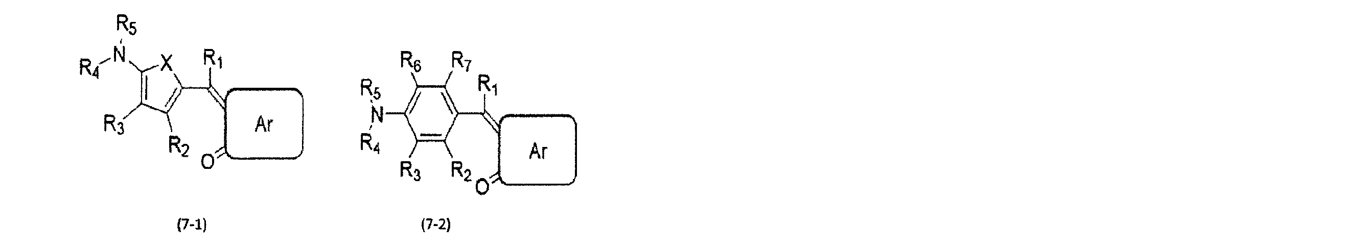
(Arは、置換若しくは無置換の2以上の縮合環、置換若しくは無置換の5員芳香族環、または置換若しくは無置換の6員芳香族環、から選ばれまたはR1~R3、R6、R7は、それぞれ独立して、水素原子、置換若しくは無置換のアルキル基、置換若しくは無置換のアリール基、置換若しくは無置換のヘテロアリール基、ハロゲン、シアノ基(-CN)、シアノ含有基、およびこれらの組み合わせから選ばれる。R4、R5は各々独立して、置換若しくは無置換のアルキル基、置換若しくは無置換のアリール基および置換若しくは無置換のヘテロアリール基である。R4、R5が置換若しくは無置換のアルキル基質の場合、それぞれはR3ないしはR6と互いに結合して環を形成しても良い。Xは、S、Se、Te、S(=O)、またはS(=O)2である。)
(Ar is selected from two or more substituted or unsubstituted condensed rings, substituted or unsubstituted 5-membered aromatic rings, or substituted or unsubstituted 6-membered aromatic rings, or R1 to R3, R6, and R7 are Each independently represents a hydrogen atom, a substituted or unsubstituted alkyl group, a substituted or unsubstituted aryl group, a substituted or unsubstituted heteroaryl group, a halogen, a cyano group (—CN), a cyano-containing group, R4 and R5 are each independently a substituted or unsubstituted alkyl group, a substituted or unsubstituted aryl group, and a substituted or unsubstituted heteroaryl group, wherein R4 and R5 are substituted or unsubstituted. In the case of an alkyl substrate, each may combine with R3 or R6 to form a ring, X is S, Se, Te, S (= O), or S (= O) 2.)
また、有機光電変換層17に含まれる第1有機半導体材料、第2有機半導体材料および第3有機半導体材料としては、例えば下記式(8)に示したクマリンおよびその誘導体が挙げられる。
Further, as the first organic semiconductor material, the second organic semiconductor material, and the third organic semiconductor material included in the organic photoelectric conversion layer 17, for example, coumarin represented by the following formula (8) and a derivative thereof are given.

(Yは酸素原子あるいは硫黄原子あるいは置換または無置換のイミノ基を表し、X1~X6はそれぞれ独立に、水素原子、ハロゲン原子、ニトロ基、シアノ基、ヒドロキシル基、カルボキシル基、スルホニル基、置換または無置換のアルキル基、置換または無置換のアラルキル基、置換または無置換のアリール基、置換または無置換のヘテロアリール基、置換または無置換のアルコキシ基、置換または無置換のアラルキルオキシ基、置換または無置換のアリールオキシ基、置換または無置換のアルキルチオ基、置換または無置換のアラルキルチオ基、置換または無置換のアリールチオ基、置換または無置換のアルキルスルホニル基、置換または無置換のアルキルアミノ基、置換または無置換のアリールスルホニル基、置換または無置換のアリールアミノ基、置換または無置換のアシルアミノ基、置換または無置換のカルボキシアミド基、置換または無置換のアシル基、置換または無置換のアシルオキシ基、置換または無置換のアルコキシカルボニル基、置換または無置換のアラルキルオキシカルボニル基、置換または無置換のアリールオキシカルボニル基、あるいは置換または無置換のアミノ基を表し、更にX1~X6から選ばれる互いに隣接する基は連結基を介して、置換している炭素原子と共に環構造を形成してもよい。)
(Y represents an oxygen atom or a sulfur atom or a substituted or unsubstituted imino group, and X1 to X6 each independently represent a hydrogen atom, a halogen atom, a nitro group, a cyano group, a hydroxyl group, a carboxyl group, a sulfonyl group, An unsubstituted alkyl group, a substituted or unsubstituted aralkyl group, a substituted or unsubstituted aryl group, a substituted or unsubstituted heteroaryl group, a substituted or unsubstituted alkoxy group, a substituted or unsubstituted aralkyloxy group, An unsubstituted aryloxy group, a substituted or unsubstituted alkylthio group, a substituted or unsubstituted aralkylthio group, a substituted or unsubstituted arylthio group, a substituted or unsubstituted alkylsulfonyl group, a substituted or unsubstituted alkylamino group, A substituted or unsubstituted arylsulfonyl group, Amino group, substituted or unsubstituted acylamino group, substituted or unsubstituted carboxamide group, substituted or unsubstituted acyl group, substituted or unsubstituted acyloxy group, substituted or unsubstituted alkoxycarbonyl group, substituted or unsubstituted Represents an aralkyloxycarbonyl group, a substituted or unsubstituted aryloxycarbonyl group, or a substituted or unsubstituted amino group, and a group adjacent to each other selected from X1 to X6 is a carbon atom which is substituted via a linking group. Together with a ring structure.)
以上説明したように、有機光電変換層を構成するバルクへテロ構造では、一般的に、アモルファス有機半導体材料のエネルギー分散が大きく、移動度が低下し易い。これに対して、第1実施形態に係る光電変換素子10によれば、有機光電変換層17が第1有機半導体材料および第2有機半導体材料を含み、第1有機半導体材料および第2有機半導体材料の少なくとも一方が、HOMO体積率またはLUMO体積率が0.15以下程度の有機分子で構成されているので、バルクヘテロ構造を構成するアモルファス有機半導体材料のエネルギー分散が小さい。このため、高い移動度を得ることができるので、優れた残像特性を得ることができる。
As described above, in the bulk hetero structure constituting the organic photoelectric conversion layer, generally, the energy dispersion of the amorphous organic semiconductor material is large, and the mobility is likely to be reduced. On the other hand, according to the photoelectric conversion element 10 according to the first embodiment, the organic photoelectric conversion layer 17 includes the first organic semiconductor material and the second organic semiconductor material, and the first organic semiconductor material and the second organic semiconductor material. Is composed of organic molecules having a HOMO volume ratio or LUMO volume ratio of about 0.15 or less, the energy dispersion of the amorphous organic semiconductor material constituting the bulk heterostructure is small. Therefore, high mobility can be obtained, and excellent afterimage characteristics can be obtained.
<実施例>
計算例1~7として、上記式(1-15)に示したペンタセン、上記式(3)に示したキナクリドン、下記式(9)に示したベンゾチエノベンゾチオフェノン誘導体(DPh-BTBT)、下記式(10)に示したF6-OC6F5、下記式(11)に示したF6-OPh2,6F2、下記式(12)に示したNTCD-Ph、下記式(13)に示したB4PyMPMについて、HOMO体積率およびLUMO体積率を計算した。 <Example>
As calculation examples 1 to 7, pentacene represented by the above formula (1-15), quinacridone represented by the above formula (3), a benzothienobenzothiophenone derivative (DPh-BTBT) represented by the following formula (9), HOMO volume of F6-OC6F5 shown in the formula (10), F6-OPh2,6F2 shown in the following formula (11), NTCD-Ph shown in the following formula (12), and B4PyMPM shown in the following formula (13) The fraction and LUMO volume fraction were calculated.


HOMO体積率とLUMO体積率の計算は密度汎関数法で行い、分子の構造最適化時には汎関数B3LYP、基底関数6-31G(d)を用い、分子軌道とエネルギー計算時には汎関数B3LYP、基底関数6-311++G(d,p)を用いた。続いて、これらの分子がそれぞれ約500分子含まれる単一組成のアモルファス構造を分子動力学法で生成した。その構造から任意の1分子を選び、その分子を中心とした半径12Å内に重心がある周辺分子(分子クラスター)を取り出した。その分子クラスターの電子状態を密度汎関数法で計算して、中心分子のHOMO準位とLUMO準位のエネルギー準位(サイトエネルギー)を求めた。同様の計算を全分子について行い、サイトエネルギーの分布を求めた。サイトエネルギー分布をガウス関数でフィッティングしてσHOMOとσLUMOを算出した。各種分子のσHOMO、σLUMOとHOMO体積率、LUMO体積率の関係を表1に示す。
Calculation of HOMO volume fraction and LUMO volume fraction is performed by density functional method, using functional B3LYP and basis function 6-31G (d) for molecular structure optimization, and functional B3LYP and basis function for molecular orbital and energy calculation. 6-311 ++ G (d, p) was used. Subsequently, a single-composition amorphous structure containing about 500 of these molecules was generated by molecular dynamics. One arbitrary molecule was selected from the structure, and peripheral molecules (molecular clusters) having a center of gravity within a radius of 12 ° around the molecule were extracted. The electronic states of the molecular clusters were calculated by density functional theory, and the energy levels (site energies) of the HOMO level and the LUMO level of the central molecule were obtained. The same calculation was performed for all molecules, and the distribution of site energy was obtained. Σ HOMO and σ LUMO were calculated by fitting the site energy distribution with a Gaussian function. Table 1 shows the relationship between σ HOMO , σ LUMO , HOMO volume ratio, and LUMO volume ratio of various molecules.

表1に示すように、計算例1,2では、HOMO体積率およびLUMO体積率のいずれもが0.15を超えた。一方、計算例3~7では、HOMO体積率およびLUMO体積率のいずれもが0.15以下となった。そのうち、計算4,5,7では、HOMO体積率およびLUMO体積率のいずれもが0.10以下となった。
よ う As shown in Table 1, in Calculation Examples 1 and 2, both the HOMO volume ratio and the LUMO volume ratio exceeded 0.15. On the other hand, in Calculation Examples 3 to 7, both the HOMO volume ratio and the LUMO volume ratio were 0.15 or less. Among them, in calculations 4, 5, and 7, both the HOMO volume ratio and the LUMO volume ratio were 0.10 or less.
表1のσHOMOとHOMO体積率の関係をプロットしたものを図4に示し、表1のσLUMOとLUMO体積率の関係をプロットしたものを図5に示す。図4および図5に示すように、σHOMOとHOMO体積率、およびσLUMOとLUMO体積率には明らかな相関が見られる。図4から、HOMO体積率が0.15以下であれば、σHOMOを0.2eV以下に抑えられることが分かる。また、図5から、LUMO体積率が0.15以下であれば、σLUMOを0.2eV以下に抑えられることが分かる。非特許文献1によると、エネルギー準位の標準偏差σを0.2eV以下に抑えると、1×10⁻⁴cm2/V・s以上の移動度を得られることが報告されている。したがって、HOMO体積率又はLUMO体積率を0.15以下の有機分子を採用することで、1×10-4cm2/V・s以上の移動度を得られるため、優れた残像特性を得ることができる。
FIG. 4 shows a plot of the relationship between σ HOMO and HOMO volume ratio in Table 1, and FIG. 5 shows a plot of the relationship between σ LUMO and LUMO volume ratio in Table 1. As shown in FIGS. 4 and 5, there is a clear correlation between σ HOMO and HOMO volume ratio and between σ LUMO and LUMO volume ratio. FIG. 4 shows that if the HOMO volume ratio is 0.15 or less, σ HOMO can be suppressed to 0.2 eV or less. Further, FIG. 5 shows that if the LUMO volume ratio is 0.15 or less, σ LUMO can be suppressed to 0.2 eV or less. According to Non-Patent Document 1, it is reported that if the standard deviation σ of the energy level is suppressed to 0.2 eV or less, a mobility of 1 × 10 −4 cm 2 / V · s or more can be obtained. Therefore, by adopting an organic molecule having a HOMO volume ratio or LUMO volume ratio of 0.15 or less, a mobility of 1 × 10 −4 cm 2 / V · s or more can be obtained, so that excellent afterimage characteristics can be obtained. Can be.
(第2実施形態)
第2実施形態に係る光電変換素子10も、図1に示した断面構造を有し、第1実施形態に係る光電変換素子の構造と共通する。しかしながら、第2実施形態に係る光電変換素子10は、有機光電変換層17の構成が第1実施形態と相違する。以下では有機光電変換層17の構成に着目して説明し、第1実施形態との共通部分の説明を省略する。 (2nd Embodiment)
Thephotoelectric conversion element 10 according to the second embodiment also has the cross-sectional structure shown in FIG. 1 and is common to the structure of the photoelectric conversion element according to the first embodiment. However, the configuration of the organic photoelectric conversion layer 17 of the photoelectric conversion element 10 according to the second embodiment is different from that of the first embodiment. The following description focuses on the configuration of the organic photoelectric conversion layer 17, and the description of the common parts with the first embodiment is omitted.
第2実施形態に係る光電変換素子10も、図1に示した断面構造を有し、第1実施形態に係る光電変換素子の構造と共通する。しかしながら、第2実施形態に係る光電変換素子10は、有機光電変換層17の構成が第1実施形態と相違する。以下では有機光電変換層17の構成に着目して説明し、第1実施形態との共通部分の説明を省略する。 (2nd Embodiment)
The
第1実施形態で既に述べた通り、有機半導体材料を用いた光電変換素子では、p型有機半導体材料とn型有機半導体材料とが不規則に混合されたバルクヘテロ構造を採用し、量子効率の向上が図られている。しかしながら、単にバルクヘテロ構造にしただけでは量子効率が十分でないことや、応答速度が遅いこと、暗電流が大きいことが課題となっている。特に暗電流の要因として、p型有機半導体材料とn型有機半導体材料の混合状態が悪く疎な膜となることで、材料界面の減少による光電変換効率の低下、材料間のキャリアの拡散の阻害、トラップ準位の生成等が起きていると推測される。そこで、第2実施形態では、p型有機半導体材料とn型有機半導体材料の混合状態を改善し、暗電流を抑制可能な光電変換素子を提供する。
As already described in the first embodiment, the photoelectric conversion element using an organic semiconductor material employs a bulk hetero structure in which a p-type organic semiconductor material and an n-type organic semiconductor material are irregularly mixed to improve quantum efficiency. Is planned. However, there are problems that the quantum efficiency is not sufficient, the response speed is slow, and the dark current is large simply by simply using the bulk hetero structure. In particular, as a cause of the dark current, a poorly mixed state of the p-type organic semiconductor material and the n-type organic semiconductor material results in a sparse film, thereby lowering the photoelectric conversion efficiency due to a decrease in the material interface and inhibiting the diffusion of carriers between the materials. It is presumed that generation of trap levels has occurred. Therefore, in the second embodiment, a photoelectric conversion element capable of improving a mixed state of a p-type organic semiconductor material and an n-type organic semiconductor material and suppressing dark current is provided.
第2実施形態に係る光電変換素子10は、図1に示すように、対向配置された下部電極(第1電極)15aおよび上部電極(第2電極)18と、下部電極15aおよび上部電極18との間に設けられた有機光電変換層17とを備える。有機光電変換層17は、2つ以上の互いに異なる母骨格を有する有機半導体材料で構成されている。有機光電変換層17は、例えば2種類の有機半導体材料で構成されていてもよく、3種類以上の有機半導体材料で構成されていてもよい。有機光電変換層17を構成する有機半導体材料は、p型半導体有機材料およびn型半導体有機材料を含む。p型半導体有機材料は、相対的に電子供与体(ドナー)として機能し、n型半導体有機材料は、相対的に電子受容体(アクセプタ)として機能する。
As shown in FIG. 1, the photoelectric conversion element 10 according to the second embodiment includes a lower electrode (first electrode) 15 a and an upper electrode (second electrode) 18 that are opposed to each other, and a lower electrode 15 a and an upper electrode 18. And an organic photoelectric conversion layer 17 provided therebetween. The organic photoelectric conversion layer 17 is made of an organic semiconductor material having two or more different mother skeletons. The organic photoelectric conversion layer 17 may be composed of, for example, two types of organic semiconductor materials, or may be composed of three or more types of organic semiconductor materials. The organic semiconductor material forming the organic photoelectric conversion layer 17 includes a p-type semiconductor organic material and an n-type semiconductor organic material. The p-type semiconductor organic material relatively functions as an electron donor (donor), and the n-type semiconductor organic material relatively functions as an electron acceptor (acceptor).
有機光電変換層17を構成する有機半導体材料の少なくとも1つは正孔輸送性材料であってよい。有機光電変換層17は、正孔輸送性材料を重量比で30%以上含むことが好ましい。正孔輸送性材料の正孔移動度は1×10⁻⁵cm2/V・s以上程度であり、好ましくは1×10-4cm2/V・s以上程度であり、より好ましくは1×10-2cm2/V・s以上程度である。
At least one of the organic semiconductor materials constituting the organic photoelectric conversion layer 17 may be a hole transporting material. The organic photoelectric conversion layer 17 preferably contains a hole transporting material in a weight ratio of 30% or more. The hole mobility of the hole transporting material is about 1 × 10 −5 cm 2 / V · s or more, preferably about 1 × 10 −4 cm 2 / V · s or more, and more preferably 1 × 10 −5 cm 2 / V · s. It is about 10 −2 cm 2 / V · s or more.
第2実施形態では、有機光電変換層17の膜密度をmとし、有機光電変換層17を構成する各有機半導体材料の単膜の膜密度の組成に対する加重平均をnとしたときに、m/nが1以上である。即ち、有機光電変換層17を構成する各有機半導体材料の相互作用によって、有機光電変換層17が、有機光電変換層17を構成する各有機半導体材料がそれぞれ単膜である場合と同等以上に密となっている状態である。m/nは1.0より大きいことが好ましく、更に、m/nは1.02以上であることがより好ましく、更に、m/nは1.04以上であることがより好ましい。
In the second embodiment, when the film density of the organic photoelectric conversion layer 17 is m and the weighted average with respect to the composition of the film density of the single film of each organic semiconductor material forming the organic photoelectric conversion layer 17 is m / m / m / n is 1 or more. That is, due to the interaction of the organic semiconductor materials constituting the organic photoelectric conversion layer 17, the organic photoelectric conversion layer 17 is denser than or equal to the case where each organic semiconductor material constituting the organic photoelectric conversion layer 17 is a single film. It is in the state of becoming. m / n is preferably larger than 1.0, more preferably m / n is 1.02 or more, and further preferably m / n is 1.04 or more.
有機光電変換層17は複数の有機半導体材料から構成されてバルクヘテロ構造となっているが、材料の組み合わせや比率によって混合状態に差が生じる。このような混合状態は材料のもつ電子の空間分布や分子形状、エネルギー順位等に影響されるため複雑であるが、単膜と混合膜の膜密度比によって規定することができる。単体で高密度な材料を集めて混合膜としても、材料間の相互作用が無い場合や疎な膜となる場合は、キャリア拡散の阻害やドメイン界面でトラップ準位が生じて、良好な特性の有機光電変換層17は得られない。
Although the organic photoelectric conversion layer 17 is composed of a plurality of organic semiconductor materials and has a bulk heterostructure, the mixed state differs depending on the combination and ratio of the materials. Such a mixed state is complicated because it is affected by the spatial distribution, molecular shape, energy order, and the like of the electrons of the material, but can be defined by the film density ratio between the single film and the mixed film. Even if a single layer of high-density material is collected to form a mixed film, if there is no interaction between the materials or the film becomes sparse, carrier diffusion is inhibited and trap levels are generated at the domain interface, resulting in good characteristics. The organic photoelectric conversion layer 17 cannot be obtained.
一方、単膜は疎であっても異なる材料と組み合わせることによって密な混合膜になる場合がある。この要因としては、同一分子同士の相互作用よりも、他の特定の分子との相互作用が強い場合や、立体形状が密なパッキングを促す形になっている等が考えられる。このような有機光電変換層17では、材料間の密着が良いことにより効率の良い光電変換およびキャリア転送が実現でき、かつ界面準位が減少することによって暗電流を低減することができる。混合性の良さは上述のm/nによって評価することができ、その定義より1.0以上であれば混合性が良い材料の組み合わせ(組成)になる。
On the other hand, a single film may become a dense mixed film by combining with a different material even if it is sparse. This may be due to a case where the interaction with another specific molecule is stronger than the interaction between the same molecules, or a case where the three-dimensional shape promotes dense packing. In such an organic photoelectric conversion layer 17, efficient photoelectric conversion and carrier transfer can be realized due to good adhesion between materials, and dark current can be reduced due to a decrease in interface states. Good mixability can be evaluated by the above-mentioned m / n. If the value is 1.0 or more according to the definition, a combination (composition) of materials having good mixability is obtained.
有機光電変換層17を構成する有機半導体材料としては、例えば、キナクリドン、塩素化ホウ素サブフタロシアニン、ペンタセン、ベンゾチエノベンゾチオフェン、フラーレンおよびそれらの誘導体等の有機半導体材料を2種以上組み合わせて構成されている。上述の有機半導体材料は、その組み合わせによってp型半導体またはn型半導体として機能する。なお、有機光電変換層17を構成する有機半導体材料としては更に、例えば、ナフタレン、アントラセン、フェナントレン、テトラセン、ピレン、ペリレン、およびフルオランテンあるいはそれらの誘導体のうちのいずれか1種が好適に用いられる。あるいは、フェニレンビニレン、フルオレン、カルバゾール、インドール、ピレン、ピロール、ピコリン、チオフェン、アセチレン、ジアセチレン等の重合体やそれらの誘導体を用いてもよい。
Examples of the organic semiconductor material constituting the organic photoelectric conversion layer 17 include a combination of two or more organic semiconductor materials such as quinacridone, boron chlorinated subphthalocyanine, pentacene, benzothienobenzothiophene, fullerene, and derivatives thereof. I have. The above-mentioned organic semiconductor materials function as a p-type semiconductor or an n-type semiconductor depending on the combination. Further, as the organic semiconductor material constituting the organic photoelectric conversion layer 17, for example, any one of naphthalene, anthracene, phenanthrene, tetracene, pyrene, perylene, and fluoranthene or a derivative thereof is preferably used. Alternatively, a polymer such as phenylenevinylene, fluorene, carbazole, indole, pyrene, pyrrole, picoline, thiophene, acetylene, diacetylene, or a derivative thereof may be used.
更に、有機光電変換層17を構成する有機半導体材料としては、例えば、金属錯体色素材料、シアニン系色素材料、メロシアニン系色素材料、フェニルキサンテン系色素材料、トリフェニルメタン系色素材料、ロダシアニン系色素材料、キサンテン系色素材料、大環状アザアヌレン系色素材料、アズレン系色素材料、ナフトキノン、アントラキノン系色素材料、アントラセンおよびピレン等の縮合多環芳香族および芳香環あるいは複素環化合物が縮合した鎖状化合物、または、スクアリリウム基およびクロコニツクメチン基を結合鎖として持つキノリン、ベンゾチアゾール、ベンゾオキサゾール等の二つの含窒素複素環、または、スクアリリウム基およびクロコニツクメチン基により結合したシアニン系類似の色素材料等を好ましく用いることができる。なお、上記金属錯体色素材料としては、ジチオール金属錯体系色素材料、金属フタロシアニン色素材料、金属ポルフィリン色素材料、またはルテニウム錯体色素材料が好ましいが、これに限定されるものではない。
Further, examples of the organic semiconductor material constituting the organic photoelectric conversion layer 17 include a metal complex dye material, a cyanine dye material, a merocyanine dye material, a phenylxanthene dye material, a triphenylmethane dye material, and a rhodacyanine dye material. , Xanthene dye material, macrocyclic azaannulene dye material, azulene dye material, naphthoquinone, anthraquinone dye material, condensed polycyclic aromatic and aromatic compounds such as anthracene and pyrene or a chain compound condensed with a heterocyclic compound, or Quinolin, benzothiazole, benzoxazole and other nitrogen-containing heterocycles having a squarylium group and a croconitum methine group as a bonding chain, or a cyanine-based dye material bonded by a squarylium group and a croconit methine group is preferable. Use Door can be. The metal complex dye material is preferably a dithiol metal complex dye material, a metal phthalocyanine dye material, a metal porphyrin dye material, or a ruthenium complex dye material, but is not limited thereto.
以上説明したように、p型有機半導体材料とn型有機半導体材料とが不規則に混合されたバルクヘテロ構造は、暗電流を抑制することが課題となっている。これに対して、第2実施形態によれば、有機光電変換層17の膜密度をmとし、有機光電変換層17を構成する各有機半導体材料の単膜の膜密度の組成に対する加重平均をnとしたときに、m/nが1以上となる有機半導体材料の組み合わせ及び組成を選択する。これにより、バルクヘテロ層中の有機分子の混合状態をより密にすることができる。このため、光電変換可能な界面の減少による光電変換効率の低下、材料間での効率的なキャリアの拡散、トラップ準位の減少によって、暗電流を低減することができる。
As described above, the problem of a bulk heterostructure in which a p-type organic semiconductor material and an n-type organic semiconductor material are irregularly mixed is to suppress dark current. On the other hand, according to the second embodiment, the film density of the organic photoelectric conversion layer 17 is m, and the weighted average with respect to the composition of the film density of the single film of each organic semiconductor material constituting the organic photoelectric conversion layer 17 is n. Then, a combination and a composition of the organic semiconductor material having m / n of 1 or more are selected. Thereby, the mixed state of the organic molecules in the bulk hetero layer can be made denser. For this reason, the dark current can be reduced due to a decrease in photoelectric conversion efficiency due to a decrease in interfaces capable of photoelectric conversion, efficient diffusion of carriers between materials, and a decrease in trap levels.
<実施例>
石英ガラス基板をUV/オゾン処理にて洗浄したのち、有機蒸着装置を用いて、1×10-5Pa以下の真空下で基板ホルダを回転させながら抵抗加熱法により有機光電変換層を成膜した。まず、下記式(14-1)に示したキナクリドン誘導体(QD),下記式(14-2)に示したキナクリドン誘導体(BQD),下記式(14-3)に示したキナクリドン誘導体(MMQD),下記式(15)に示したBP-ChDT,上記式(6-1)に示したC60,下記式(16)に示したF6-SubPc-F,下記式(17)に示したサブフタロシアニン誘導体(F6-SubPc-OPh2,6F2)の単膜をそれぞれ成膜し、試料1~7とした。その後、化合物の組み合わせおよび成膜レート比がQD:F6-SubPc-F=5:5、QD:F6-SubPc-F=7:3、BQD:QD:F6-SubPc-F=3.5:3.5:3、BP-ChDT:C60:F6-SubPc-OPh2,6F2=3;3:4、BP-ChDT:C60:F6-SubPc-OPh2,6F2=4:24:4:2の共蒸着膜をそれぞれ成膜し、試料8~12とした。試料1~7の単膜の膜厚を50nm、試料8~12の共蒸着膜の膜厚を230nmとした。 <Example>
After the quartz glass substrate was washed by UV / ozone treatment, an organic photoelectric conversion layer was formed by a resistance heating method using an organic vapor deposition apparatus while rotating the substrate holder under a vacuum of 1 × 10 −5 Pa or less. . First, a quinacridone derivative (QD) represented by the following formula (14-1), a quinacridone derivative (BQD) represented by the following formula (14-2), a quinacridone derivative (MMQD) represented by the following formula (14-3), BP-ChDT shown in the following formula (15), C60 shown in the above formula (6-1), F6-SubPc-F shown in the following formula (16), and subphthalocyanine derivative shown in the following formula (17) ( Single films of F6-SubPc-OPh2, 6F2) were formed, respectively, to obtainsamples 1 to 7. Thereafter, the combination of compounds and the film formation rate ratio were QD: F6-SubPc-F = 5: 5, QD: F6-SubPc-F = 7: 3, BQD: QD: F6-SubPc-F = 3.5: 3. 0.5: 3, BP-ChDT: C60: F6-SubPc-OPh2,6F2 = 3; 3: 4, BP-ChDT: C60: F6-SubPc-OPh2,6F2 = 4: 24: 4: 2 codeposited film Were formed as Samples 8 to 12, respectively. The thickness of the single film of Samples 1 to 7 was 50 nm, and the thickness of the co-evaporated film of Samples 8 to 12 was 230 nm.
石英ガラス基板をUV/オゾン処理にて洗浄したのち、有機蒸着装置を用いて、1×10-5Pa以下の真空下で基板ホルダを回転させながら抵抗加熱法により有機光電変換層を成膜した。まず、下記式(14-1)に示したキナクリドン誘導体(QD),下記式(14-2)に示したキナクリドン誘導体(BQD),下記式(14-3)に示したキナクリドン誘導体(MMQD),下記式(15)に示したBP-ChDT,上記式(6-1)に示したC60,下記式(16)に示したF6-SubPc-F,下記式(17)に示したサブフタロシアニン誘導体(F6-SubPc-OPh2,6F2)の単膜をそれぞれ成膜し、試料1~7とした。その後、化合物の組み合わせおよび成膜レート比がQD:F6-SubPc-F=5:5、QD:F6-SubPc-F=7:3、BQD:QD:F6-SubPc-F=3.5:3.5:3、BP-ChDT:C60:F6-SubPc-OPh2,6F2=3;3:4、BP-ChDT:C60:F6-SubPc-OPh2,6F2=4:24:4:2の共蒸着膜をそれぞれ成膜し、試料8~12とした。試料1~7の単膜の膜厚を50nm、試料8~12の共蒸着膜の膜厚を230nmとした。 <Example>
After the quartz glass substrate was washed by UV / ozone treatment, an organic photoelectric conversion layer was formed by a resistance heating method using an organic vapor deposition apparatus while rotating the substrate holder under a vacuum of 1 × 10 −5 Pa or less. . First, a quinacridone derivative (QD) represented by the following formula (14-1), a quinacridone derivative (BQD) represented by the following formula (14-2), a quinacridone derivative (MMQD) represented by the following formula (14-3), BP-ChDT shown in the following formula (15), C60 shown in the above formula (6-1), F6-SubPc-F shown in the following formula (16), and subphthalocyanine derivative shown in the following formula (17) ( Single films of F6-SubPc-OPh2, 6F2) were formed, respectively, to obtain


X線反射率法(XRR)を用いて試料1~7の単膜の膜密度と、試料8~12の共蒸着膜の膜密度をそれぞれ算出した。測定条件を表2に示す。表2の走査軸の設定値の「2θ/θ」は、試料に対するX線の視斜角が検出器角度2θの丁度半分になるように走査することを示す。
単 The film densities of the single films of Samples 1 to 7 and the film densities of the co-evaporated films of Samples 8 to 12 were calculated using X-ray reflectivity (XRR). Table 2 shows the measurement conditions. “2θ / θ” of the setting value of the scanning axis in Table 2 indicates that scanning is performed such that the viewing angle of the X-ray with respect to the sample is exactly half the detector angle 2θ.

XRRの測定結果から算出した、試料1~7の単膜の膜密度を表3に示す。
Table 3 shows the film densities of the single films of Samples 1 to 7 calculated from the measurement results of XRR.

また、試料8~12について、試料8~12の共蒸着膜の膜密度mと、試料1~7の単膜の膜密度と組成比から算出した膜密度の加重平均nと、加重平均nに対する膜密度mの比m/nと、暗電流特性を表4に示す。
For samples 8 to 12, the film density m of the co-evaporated film of samples 8 to 12, the weighted average n of the film density calculated from the film density and the composition ratio of the single films of samples 1 to 7, and the weighted average n Table 4 shows the ratio m / n of the film density m and the dark current characteristics.

表4から、試料8,10のようにm/nが1.0未満である場合には、暗電流が10-8A/cm2台以上となり、暗電流特性が良好でないことが分かる。一方、試料9,11,12のようにm/nが1.0以上である場合には、暗電流が10-9A/cm2台以下となり、良好な暗電流特性が得られたことが分かる。このうち、試料11,12のようにm/nが1.02以上である場合には、暗電流が10-10A/cm2台以下となり、更に良好な暗電流特性が得られたことが分かる。このうち、試料12のようにm/nが1.04以上である場合には、暗電流が10-11A/cm2台以下となり、更に良好な暗電流特性が得られたことが分かる。また、試料8,9のように材料が同一でも組成を異ならせることで、m/nおよび暗電流特性が変化することが分かる。
Table 4 shows that when m / n is less than 1.0 as in Samples 8 and 10, the dark current is not less than 10 −8 A / cm 2 and the dark current characteristics are not good. On the other hand, when m / n is 1.0 or more as in Samples 9, 11, and 12, the dark current is not more than 10 −9 A / cm 2 , indicating that good dark current characteristics were obtained. I understand. When m / n is 1.02 or more as in Samples 11 and 12, the dark current is less than 10 −10 A / cm 2 , indicating that better dark current characteristics were obtained. I understand. Among them, when m / n is 1.04 or more as in Sample 12, the dark current becomes 10 −11 A / cm 2 or less, and it is understood that further excellent dark current characteristics were obtained. Further, it can be seen that the m / n and the dark current characteristics are changed by changing the composition even if the materials are the same as in Samples 8 and 9.
(第3実施形態)
第3実施形態に係る光電変換素子10も、図1に示した断面構造を有し、第1および第2実施形態に係る光電変換素子の構造と共通する。しかしながら、第3実施形態に係る光電変換素子10は、有機光電変換層17の構成が第1および第2実施形態と相違する。以下では有機光電変換層17の構成に着目して説明し、第1および第2実施形態との共通部分の説明を省略する。 (Third embodiment)
Thephotoelectric conversion element 10 according to the third embodiment also has the cross-sectional structure shown in FIG. 1 and is common to the structures of the photoelectric conversion elements according to the first and second embodiments. However, the photoelectric conversion element 10 according to the third embodiment is different from the first and second embodiments in the configuration of the organic photoelectric conversion layer 17. The following description focuses on the configuration of the organic photoelectric conversion layer 17, and a description of common parts with the first and second embodiments will be omitted.
第3実施形態に係る光電変換素子10も、図1に示した断面構造を有し、第1および第2実施形態に係る光電変換素子の構造と共通する。しかしながら、第3実施形態に係る光電変換素子10は、有機光電変換層17の構成が第1および第2実施形態と相違する。以下では有機光電変換層17の構成に着目して説明し、第1および第2実施形態との共通部分の説明を省略する。 (Third embodiment)
The
第1および第2実施形態で既に述べた通り、図1に示した有機光電変換層17は、p型有機半導体材料とn型有機半導体材料とが不規則に混合したバルクヘテロ構造を有する。バルクヘテロ層では半導体材料がアモルファス状態で存在することが多い。一般的にアモルファス有機半導体では、図2及び図3に模式的に示すように、個々の分子のキャリア伝導エネルギー準位が空間的に変動している。この変動したプロファイルは、キャリア移動にとってエネルギー障壁となるので、キャリア伝導エネルギー準位のエネルギー分散σが大きいほどキャリア移動度が低下する。一般的にアモルファス有機半導体は結晶に比べてエネルギー分散σが大きいため移動度が低い。移動度が低下すると、電荷分離界面で発生した電荷が電極に到達までに要する時間が長くなるため、光電変換素子の残像特性が低下するという課題がある。
As described in the first and second embodiments, the organic photoelectric conversion layer 17 shown in FIG. 1 has a bulk heterostructure in which a p-type organic semiconductor material and an n-type organic semiconductor material are mixed irregularly. In the bulk hetero layer, the semiconductor material often exists in an amorphous state. Generally, in an amorphous organic semiconductor, as shown schematically in FIGS. 2 and 3, the carrier conduction energy level of each molecule fluctuates spatially. Since this fluctuated profile becomes an energy barrier for carrier movement, the carrier mobility decreases as the energy dispersion σ of the carrier conduction energy level increases. Generally, an amorphous organic semiconductor has a lower mobility because of a larger energy dispersion σ than a crystal. When the mobility decreases, the time required for the charges generated at the charge separation interface to reach the electrodes becomes longer, and thus the afterimage characteristics of the photoelectric conversion element deteriorate.
ところで、固体撮像装置の画素等として用いる光電変換素子においては、外部量子効率(EQE)の改善が求められている。EQEの改善には光吸収量を向上させ、かつ励起子の電荷分離効率を良くすることが望ましい。そこで、例えば、バルクヘテロ接合型の光電変換素子において、ドナーおよびアクセプタ材料に更に色素材料を加えることで、膜体積当たりの光吸収効率を上げることが考えられる。しかしながら、色素材料の添加は膜中のドナーまたはアクセプタに配位することで前述のエネルギー分散σを増大させる恐れがある。そこで、第3実施形態では、ドナーおよびアクセプタに配位する色素材料の構造を制御することで、残像特性低下の抑制と高いEQEを両立した光電変換素子を提供する。
By the way, in a photoelectric conversion element used as a pixel or the like of a solid-state imaging device, improvement in external quantum efficiency (EQE) is required. In order to improve the EQE, it is desirable to improve the light absorption amount and the charge separation efficiency of excitons. Therefore, for example, in a bulk heterojunction photoelectric conversion element, it is conceivable to increase the light absorption efficiency per film volume by further adding a dye material to the donor and acceptor materials. However, the addition of the dye material may increase the above-mentioned energy dispersion σ by coordinating to the donor or acceptor in the film. Thus, in the third embodiment, a photoelectric conversion element that achieves both suppression of afterimage characteristics degradation and high EQE is provided by controlling the structure of a dye material that coordinates to a donor and an acceptor.
第3実施形態に係る光電変換素子10は、図1に示すように、対向配置された下部電極(第1電極)15aおよび上部電極(第2電極)18と、下部電極15aおよび上部電極18との間に設けられた有機光電変換層17とを備える。有機光電変換層17が、互いに異なる母骨格を有する第1~第3有機半導体材料を含む。第1有機半導体材料は電子供与性を有し、第2有機半導体材料は電子受容性を有し、第3有機半導体材料は光を吸収して励起する色素材料である。第1有機半導体材料および第2有機半導体材料は、p型半導体有機材料およびn型半導体有機材料でそれぞれ構成される。p型有機半導体材料は、相対的に電子供与体(ドナー)として機能し、n型有機半導体材料は、相対的に電子受容体(アクセプタ)として機能する。
As shown in FIG. 1, the photoelectric conversion element 10 according to the third embodiment includes a lower electrode (first electrode) 15a and an upper electrode (second electrode) 18 which are opposed to each other, a lower electrode 15a and an upper electrode 18, And an organic photoelectric conversion layer 17 provided therebetween. The organic photoelectric conversion layer 17 includes first to third organic semiconductor materials having different mother skeletons. The first organic semiconductor material has an electron donating property, the second organic semiconductor material has an electron accepting property, and the third organic semiconductor material is a dye material that absorbs and excites light. The first organic semiconductor material and the second organic semiconductor material are respectively composed of a p-type semiconductor organic material and an n-type semiconductor organic material. The p-type organic semiconductor material relatively functions as an electron donor (donor), and the n-type organic semiconductor material relatively functions as an electron acceptor (acceptor).
第3実施形態では、有機光電変換層17内の第2有機半導体材料の総数NAに対して、第2有機半導体材料が隣接する第3有機半導体材料との配位構造として最も安定な構造のみである第2有機半導体材料の個数Nの比率N/NAが0.5以上程度である。NA/Nは、例えば0.5以上1.0以下であってよく1.0に近いほど好ましい。
In the third embodiment, the total number N A of the second organic semiconductor material of an organic photoelectric conversion layer 17, the most stable structure as a coordination structure of the third organic semiconductor material in which the second organic semiconductor material adjacent only the ratio N / N a number N of the second organic semiconductor material is is on the order of 0.5 or more. N A / N may be, for example, 0.5 or more and 1.0 or less, and the closer to 1.0, the more preferable.
ここで、有機半導体材料は、その周囲に配位する有機材料との相互作用によりエネルギー準位が変化するため、色素材料が配合されることによりエネルギー準位のばらつきが増大し、電子移動度が低下することが懸念される。つまり、有機光電変換層に配合される色素材料としては、有機半導体材料に与える相互作用が均一であることが望ましい。有機材料間の相互作用は配位構造によって変化する。即ち、有機光電変換層に含まれる色素材料と有機半導体材料との配位構造は、なるべく一種類に揃っていることが望ましい。図6Aに模式的に、色素材料である第3有機半導体材料31と第2有機半導体材料32の配位構造が揃っていない状態を示し、図6Bに模式的に、色素材料である第3有機半導体材料31と第2有機半導体材料32の配位構造が揃っている状態を示す。
Here, the energy level of the organic semiconductor material changes due to the interaction with the organic material coordinated around the organic semiconductor material. It is feared that it will decrease. That is, it is desirable that the dye material blended in the organic photoelectric conversion layer has a uniform interaction with the organic semiconductor material. Interaction between organic materials varies depending on the coordination structure. That is, it is desirable that the coordination structure of the dye material and the organic semiconductor material contained in the organic photoelectric conversion layer be as uniform as possible. FIG. 6A schematically shows a state in which the coordination structures of the third organic semiconductor material 31 and the second organic semiconductor material 32 which are the dye materials are not uniform, and FIG. 6B schematically shows the third organic semiconductor material 31 which is the dye material. This shows a state where the coordination structures of the semiconductor material 31 and the second organic semiconductor material 32 are aligned.
有機光電変換層17内の配位構造が一種類に揃っている指標としては、配位構造の分布の偏りを見ればよい。有機光電変換層17内の色素材料と有機半導体の配位構造の分布は、量子化学計算などのコンピューターシミュレーションで算出することができる。また、色素材料と有機半導体の配位構造分布は、実験による解析からも同定することができる。例えば、ラマン分光、赤外分光(IR)、フォトルミネッセンス(PL)などの分光解析によって分子の配向構造に由来したピーク分離ができれば、そのピーク強度比から、配位構造の比を求めることができる。即ち、膜中に存在する色素材料と有機半導体材料の配位構造比を実験から算出することが原理的に可能である。
指標 As an index that the coordination structures in the organic photoelectric conversion layer 17 are arranged in one type, it is sufficient to see the bias of the distribution of the coordination structures. The distribution of the coordination structure between the dye material and the organic semiconductor in the organic photoelectric conversion layer 17 can be calculated by computer simulation such as quantum chemical calculation. Further, the coordination structure distribution of the dye material and the organic semiconductor can be identified from an analysis based on experiments. For example, if peak separation derived from the molecular orientation structure can be performed by spectral analysis such as Raman spectroscopy, infrared spectroscopy (IR), and photoluminescence (PL), the ratio of the coordination structure can be determined from the peak intensity ratio. . That is, it is possible in principle to calculate the coordination structure ratio between the dye material and the organic semiconductor material existing in the film from an experiment.
N/NAは、例えば、以下のように求めることができる。まず、図7に模式的に示すように、量子化学計算により、色素材料である第3有機半導体材料31と、第2有機半導体材料32との最も安定な二量体構造を求める。図7では、第3有機半導体材料31がお椀型(傘状)であり、第2有機半導体材料32が略球形である場合を模式的に示している。更に、二量体構造における第3有機半導体材料31の重心C1と第2有機半導体材料32の重心C2を通る軸aに対して垂直であり、かつ第3有機半導体材料31の重心C1を通る面で分断する分断面Sを定義する。更に、その分断面Sで定義された2つの領域のうち、第2有機半導体材料32が有る側の領域を「領域A」、第2有機半導体材料の無い側を「領域B」として定義する。この定義により、任意の二量体構造を領域Aまたは領域Bの2つに分類することができる。
N / N A, for example, can be determined as follows. First, as shown schematically in FIG. 7, the most stable dimer structure between the third organic semiconductor material 31 and the second organic semiconductor material 32, which are dye materials, is obtained by quantum chemical calculation. FIG. 7 schematically illustrates a case where the third organic semiconductor material 31 is bowl-shaped (umbrella-shaped) and the second organic semiconductor material 32 is substantially spherical. Furthermore, a plane perpendicular to the axis a passing through the center of gravity C1 of the third organic semiconductor material 31 and the center of gravity C2 of the second organic semiconductor material 32 in the dimer structure, and passing through the center of gravity C1 of the third organic semiconductor material 31 Is used to define a dividing section S. Further, of the two regions defined by the sectional plane S, a region where the second organic semiconductor material 32 exists is defined as “region A”, and a region where the second organic semiconductor material 32 does not exist is defined as “region B”. According to this definition, an arbitrary dimer structure can be classified into two regions, region A and region B.
光電変換層17内の第2有機半導体材料のうち、第2有機半導体材料32に隣接する第3有機半導体材料31から見て第2有機半導体材料32が領域Aにのみ位置する第2有機半導体材料32の個数をNAとし、光電変換層17内の第2有機半導体材料32の総数をNとして、NA/Nを算出することができる。この際、第2有機半導体材料32と第3有機半導体材料31の重心間距離が1.0nm以内の場合に、第2有機半導体材料32と色素材料31が隣接しているものとみなす。
Among the second organic semiconductor materials in the photoelectric conversion layer 17, the second organic semiconductor material in which the second organic semiconductor material 32 is located only in the region A when viewed from the third organic semiconductor material 31 adjacent to the second organic semiconductor material 32 32 number of the N a, the total number of the second organic semiconductor material 32 of the photoelectric conversion layer 17 as N, can be calculated N a / N. At this time, when the distance between the centers of gravity of the second organic semiconductor material 32 and the third organic semiconductor material 31 is within 1.0 nm, it is considered that the second organic semiconductor material 32 and the dye material 31 are adjacent to each other.
例えば、図7に示した最も安定な二量体構造では、第2有機半導体材料32に隣接する第3有機半導体材料31から見てその第2有機半導体材料32が領域Aにのみ位置するので、第2有機半導体材料32はNAに含まれる。また、図8A~図8Cに示すように、二量体構造が第2有機半導体材料32とそれに隣接する複数の第3有機半導体材料31で構成されていてもよい。図8A及び図8Bに示した構造の場合、第2有機半導体材料32に隣接する各第3有機半導体材料31から見て第2有機半導体材料32が領域Aにのみ位置するので、図8A及び図8Bに示した各第2有機半導体材料32はNAに含まれる。一方、図8Cに示した構造の場合、上側の第3有機半導体材料31から見て第2有機半導体材料32が領域Aに位置するが、下側の第3有機半導体材料31から見て第2有機半導体材料32が領域Bに位置するため、図8Cに示した各第2有機半導体材料32はNAに含まれない。なお、図8A及び図8Bでは第2有機半導体材料32に隣接する第3有機半導体材料31が2個及び3個である場合をそれぞれ例示するが、第2有機半導体材料32に隣接する第3有機半導体材料31が3次元的に4個以上存在してもよい。
For example, in the most stable dimer structure shown in FIG. 7, since the second organic semiconductor material 32 is located only in the region A when viewed from the third organic semiconductor material 31 adjacent to the second organic semiconductor material 32, the second organic semiconductor material 32 is included in N a. As shown in FIGS. 8A to 8C, the dimer structure may be composed of the second organic semiconductor material 32 and a plurality of third organic semiconductor materials 31 adjacent thereto. In the case of the structure shown in FIGS. 8A and 8B, the second organic semiconductor material 32 is located only in the region A when viewed from each third organic semiconductor material 31 adjacent to the second organic semiconductor material 32. the second organic semiconductor material 32 each shown in 8B is included in N a. On the other hand, in the structure shown in FIG. 8C, the second organic semiconductor material 32 is located in the region A when viewed from the upper third organic semiconductor material 31, but the second organic semiconductor material 32 is viewed from the lower third organic semiconductor material 31. since the organic semiconductor material 32 is positioned in the region B, the second organic semiconductor material 32 each shown in FIG. 8C is not included in the N a. FIGS. 8A and 8B illustrate the case where the number of the third organic semiconductor materials 31 adjacent to the second organic semiconductor material 32 is two and three, respectively, but the third organic semiconductor material 31 adjacent to the second organic semiconductor material 32 is illustrated. Four or more semiconductor materials 31 may be present three-dimensionally.
有機光電変換層17において、NA/Nを0.5以上にするには、有機光電変換層17のモルフォロジーを改変することが有効である。例えば、有機光電変換層17の蒸着温度や蒸着レート、有機光電変換層17の下地を調整することにより、有機光電変換層17のモルフォロジーを改変することができる。また、有機光電変換層17において、NA/Nを0.5以上にするには、色素材料の分子構造を改善することが有効である。例えば、第3有機半導体材料と第2有機半導体材料における特定の二量体構造を、極端に安定化させることにより、有機光電変換層17中での構造を揃えることができる。また、第3有機半導体材料の構造を対称にし、1つの第3有機半導体材料に対して同じ配位構造をもつ第2有機半導体材料を複数隣接させることで、配位構造として最も安定な構造のみである比率を増やすことができる。
To make N A / N 0.5 or more in the organic photoelectric conversion layer 17, it is effective to modify the morphology of the organic photoelectric conversion layer 17. For example, the morphology of the organic photoelectric conversion layer 17 can be changed by adjusting the deposition temperature and the deposition rate of the organic photoelectric conversion layer 17 and the base of the organic photoelectric conversion layer 17. In order to make N A / N 0.5 or more in the organic photoelectric conversion layer 17, it is effective to improve the molecular structure of the coloring material. For example, the structure in the organic photoelectric conversion layer 17 can be made uniform by extremely stabilizing a specific dimer structure in the third organic semiconductor material and the second organic semiconductor material. Further, by making the structure of the third organic semiconductor material symmetrical and making a plurality of second organic semiconductor materials having the same coordination structure adjacent to one third organic semiconductor material, only the most stable coordination structure can be obtained. Can be increased.
有機光電変換層17に含まれる第1有機半導体材料および第2有機半導体材料としては、例えば、キナクリドン、塩素化ホウ素サブフタロシアニン、ペンタセン、ベンゾチエノベンゾチオフェン、フラーレンおよびそれらの誘導体等の有機半導体材料を2種以上組み合わせて構成されている。上記有機半導体材料は、その組み合わせによってp型半導体またはn型半導体として機能する。なお、有機光電変換層17に含まれる第1有機半導体材料および第2有機半導体材料としては更に、例えば、ナフタレン、アントラセン、フェナントレン、テトラセン、ピレン、ペリレン、およびフルオランテンあるいはそれらの誘導体のうちのいずれか1種が好適に用いられる。あるいは、フェニレンビニレン、フルオレン、カルバゾール、インドール、ピレン、ピロール、ピコリン、チオフェン、アセチレン、ジアセチレン等の重合体やそれらの誘導体を用いてもよい。
Examples of the first organic semiconductor material and the second organic semiconductor material included in the organic photoelectric conversion layer 17 include organic semiconductor materials such as quinacridone, boron chlorinated subphthalocyanine, pentacene, benzothienobenzothiophene, fullerene, and derivatives thereof. It is configured by combining two or more types. The organic semiconductor material functions as a p-type semiconductor or an n-type semiconductor depending on the combination. The first organic semiconductor material and the second organic semiconductor material included in the organic photoelectric conversion layer 17 further include, for example, naphthalene, anthracene, phenanthrene, tetracene, pyrene, perylene, and fluoranthene, or any of derivatives thereof. One type is suitably used. Alternatively, a polymer such as phenylenevinylene, fluorene, carbazole, indole, pyrene, pyrrole, picoline, thiophene, acetylene, diacetylene, or a derivative thereof may be used.
有機光電変換層17に含まれる色素材料としての第3有機半導体材料は、高い吸光度を持つことが望ましい。第3有機半導体材料としては、金属錯体色素材料、シアニン系色素材料、メロシアニン系色素材料、フェニルキサンテン系色素材料、トリフェニルメタン系色素材料、ロダシアニン系色素材料、キサンテン系色素材料、大環状アザアヌレン系色素材料、アズレン系色素材料、ナフトキノン、アントラキノン系色素材料、アントラセンおよびピレン等の縮合多環芳香族および芳香環あるいは複素環化合物が縮合した鎖状化合物、または、スクアリリウム基およびクロコニツクメチン基を結合鎖として持つキノリン、ベンゾチアゾール、ベンゾオキサゾール等の二つの含窒素複素環、または、スクアリリウム基およびクロコニツクメチン基により結合したシアニン系類似の色素材料等を好ましく用いることができる。なお、上記金属錯体色素材料としては、ジチオール金属錯体系色素材料、金属フタロシアニン色素材料、金属ポルフィリン色素材料、またはルテニウム錯体色素材料が好ましいが、これに限定されるものではない。
3 The third organic semiconductor material as a dye material contained in the organic photoelectric conversion layer 17 preferably has a high absorbance. Examples of the third organic semiconductor material include a metal complex dye material, a cyanine dye material, a merocyanine dye material, a phenylxanthene dye material, a triphenylmethane dye material, a rhodacyanine dye material, a xanthene dye material, and a macrocyclic azaannulene dye material. Dye material, azulene-based dye material, naphthoquinone, anthraquinone-based dye material, condensed polycyclic aromatic and aromatic compounds such as anthracene and pyrene or a chain compound condensed with a heterocyclic compound, or squarylium group and croconitum methine group Two nitrogen-containing heterocycles such as quinoline, benzothiazole, and benzoxazole having a chain, or a cyanine-based dye material linked by a squarylium group and a croconite methine group can be preferably used. The metal complex dye material is preferably a dithiol metal complex dye material, a metal phthalocyanine dye material, a metal porphyrin dye material, or a ruthenium complex dye material, but is not limited thereto.
また、有機光電変換層17に含まれる第1有機半導体材料、第2有機半導体材料、第3有機半導体材料の混合割合としては、例えば第1有機半導体材料が30重量%程度、第2有機半導体材料が30重量%程度、色素材料が40重量%程度であってよいが、これに限定されない。
The mixing ratio of the first organic semiconductor material, the second organic semiconductor material, and the third organic semiconductor material contained in the organic photoelectric conversion layer 17 is, for example, about 30% by weight of the first organic semiconductor material, May be about 30% by weight and the coloring material is about 40% by weight, but is not limited thereto.
以上説明したように、有機半導体材料を用いた光電変換素子において、EQEを改善するために、有機光電変換層に色素材料を配合することが考えられるが、これによりエネルギー準位の変動が大きくなり、残像特性が低下する懸念がある。これに対して、第3実施形態に係る光電変換素子10によれば、有機光電変換層17に、電子供与性及び電子受容性をそれぞれ有する第1及び第2有機半導体材料に加えて、第3有機半導体材料として色素材料を配合することにより光吸収効率を上げて、光電変換効率を向上させることができる。更に、有機光電変換層17内の第2有機半導体材料の総数NAに対して、第2有機半導体材料が隣接する第3有機半導体材料との配位構造として最も安定な構造のみである第2有機半導体材料の個数Nの比率N/NAが0.5以上となる配位構造が制御された組み合わせを選択することで、エネルギー分散の増大を抑制することができ、残像特性の低下を防止することができる。したがって、優れた残像特性と高いEQEを両立した光電変換素子10を提供することができる。
As described above, in a photoelectric conversion element using an organic semiconductor material, it is conceivable to mix a dye material in the organic photoelectric conversion layer in order to improve EQE, but this leads to a large change in energy level. However, there is a concern that the afterimage characteristics may be reduced. On the other hand, according to the photoelectric conversion element 10 according to the third embodiment, the organic photoelectric conversion layer 17 includes, in addition to the first and second organic semiconductor materials each having an electron donating property and an electron accepting property, a third By blending a dye material as an organic semiconductor material, light absorption efficiency can be increased and photoelectric conversion efficiency can be improved. Furthermore, the total number N A of the second organic semiconductor material of an organic photoelectric conversion layer 17, first second organic semiconductor material is only the most stable structure as a coordination structure of the third organic semiconductor material adjacent 2 the ratio N / N a number N of the organic semiconductor material by selecting the combination of coordination structure is controlled to be 0.5 or more, it is possible to suppress an increase in the energy dispersion, prevent deterioration in afterimage characteristics can do. Therefore, it is possible to provide the photoelectric conversion element 10 having both excellent afterimage characteristics and high EQE.
<実施例>
まず、第2有機半導体材料(n型有機半導体材料)として上記式(6-1)に示したC60、第3有機半導体材料(色素材料)として上記式(11)に示したF6-OPh2,6F2を採用し、C60およびF6-OPh2,6F2についての最も安定な二量体構造を求めた。計算は密度汎関数法で行い、分子の構造最適化時には汎関数B3LYP、基底関数6-31G(d)を用い、分子軌道とエネルギー計算時には汎関数B3LYP、基底関数6-311++G(d,p)を用いた。 <Example>
First, as a second organic semiconductor material (n-type organic semiconductor material), C60 shown in the above formula (6-1), and as a third organic semiconductor material (dye material), F6-OPh2,6F2 shown in the above formula (11). Was used to determine the most stable dimer structures for C60 and F6-OPh2,6F2. The calculation is performed by the density functional method, and the functional B3LYP and the basis function 6-31G (d) are used when optimizing the molecular structure, and the functional B3LYP and the basis function 6-311 ++ G (d , p) was used.
これらの最も安定な二量体構造から、配位構造を特徴づけるための定義を行う。まず、図7に模式的に示すように、二量体構造における第3有機半導体材料31としてのF6-OPh2,6F2の重心C1と第2有機半導体材料32としてのC60の重心C2を通る軸aに対して垂直であり、かつ重心C1を通る面で分断する分断面Sを定義する。そして、その分断面Sで定義された2つの領域のうち、第2有機半導体材料32としてのC60が有る側の領域を「領域A」、第2有機半導体材料32としてのC60の無い側を「領域B」として定義する。この定義により、任意の二量体構造を領域Aまたは領域Bの2つに分類することができる。
定義 From these most stable dimer structures, define to characterize the coordination structure. First, as schematically shown in FIG. 7, an axis a passing through the center of gravity C1 of F6-OPh2,6F2 as the third organic semiconductor material 31 and the center of gravity C2 of C60 as the second organic semiconductor material 32 in the dimer structure. , And a dividing plane S which is divided by a plane passing through the center of gravity C1 is defined. Then, of the two regions defined by the sectional plane S, the region having C60 as the second organic semiconductor material 32 is referred to as “region A”, and the side having no C60 as the second organic semiconductor material 32 is referred to as “region A”. Region B ". According to this definition, an arbitrary dimer structure can be classified into two regions, region A and region B.
続いて配位構造の分布を求めるため、第3有機半導体材料31としてのF6-OPh2,6F2と第2有機半導体材料32としてのC60がそれぞれ約1000分子含まれる二元相溶のアモルファス構造を分子動力学法で生成した。分子動力学法で利用される力場は、非特許文献3に開示されたGAFF(General Amber Force Field)を利用した。
Subsequently, in order to obtain the distribution of the coordination structure, the binary compatible amorphous structure containing about 1000 molecules of F6-OPh2,6F2 as the third organic semiconductor material 31 and about 1000 molecules of C60 as the second organic semiconductor material 32 was used. Generated by kinetic method. As a force field used in the molecular dynamics method, GAFF (General Amber Force Field) disclosed in Non-Patent Document 3 was used.
図9に、分子動力学法で生成した二元相溶のアモルファス構造における配位構造の分布を示す。図9の横軸は、第2有機半導体材料32としてのC60と、第3有機半導体材料31としてのF6-OPh2,6F2の重心間距離rを示す。図9の縦軸は、図10A~図10Cに模式的に示すように、第3有機半導体材料31としてのF6-OPh2,6F2の分断面Sに対し領域A方向の法線ベクトルv1と、第2有機半導体材料32としてのC60の重心C1からF6-OPh2,6F2の重心C2を結ぶベクトルv2とのなす角度θを示す。なお、前述の分断面Sの定義より、図10Aに示すようにcosθ=-1が最も安定な二量体構造に対応する。図10Bに示すようにcosθ<0の領域は領域Aに対応し、図10Cに示すようにcosθ>0の領域は領域Bに対応する。図9で、領域Aに点が密集している周辺が、C60とF6-OPh2,6F2が最も安定となる二量体構造に近い配位構造として抽出できる。一方、領域Bの点は、安定な二量体構造とは別の配位構造になる。
FIG. 9 shows the distribution of the coordination structure in the binary compatible amorphous structure generated by the molecular dynamics method. The horizontal axis in FIG. 9 indicates the distance r between the centers of gravity of C60 as the second organic semiconductor material 32 and F6-OPh2,6F2 as the third organic semiconductor material 31. As shown schematically in FIGS. 10A to 10C, the vertical axis in FIG. 9 indicates the normal vector v1 in the direction of the region A with respect to the sectional plane S of F6-OPh2,6F2 as the third organic semiconductor material 31, 2 shows an angle θ between the center of gravity C1 of C60 as the organic semiconductor material 32 and the vector v2 connecting the center of gravity C2 of F6-OPh2,6F2. According to the definition of the division plane S, cos θ = −1 corresponds to the most stable dimer structure as shown in FIG. 10A. The area where cos θ <0 corresponds to the area A as shown in FIG. 10B, and the area where cos θ> 0 corresponds to the area B as shown in FIG. In FIG. 9, the periphery where the points are dense in the region A can be extracted as a coordination structure close to a dimer structure in which C60 and F6-OPh2,6F2 are most stable. On the other hand, the point in the region B has a different coordination structure from the stable dimer structure.
次に、上記で作成した構造におけるC60のエネルギー準位のばらつきを評価した。構造から任意の1分子を選び、その分子を中心とした半径12Å内に重心がある周辺分子(分子クラスター)を取り出した。その分子クラスターの電子状態を密度汎関数法で計算して、中心分子のHOMO準位とLUMO準位のエネルギー準位(サイトエネルギー)を求めた。同様の計算をC60全分子について行い、サイトエネルギーの分布を求めた。サイトエネルギー分布をガウス関数でフィッティングし、LUMO準位の標準偏差σLUMOを算出した。
Next, the variation in the energy level of C60 in the structure created above was evaluated. An arbitrary molecule was selected from the structure, and a peripheral molecule (molecular cluster) having a center of gravity within a radius of 12 ° centered on the molecule was extracted. The electronic states of the molecular clusters were calculated by density functional theory, and the energy levels (site energies) of the HOMO level and the LUMO level of the central molecule were obtained. The same calculation was performed for all molecules of C60, and the distribution of site energy was obtained. The site energy distribution was fitted with a Gaussian function, and the standard deviation σ LUMO of the LUMO level was calculated.
次に、配位構造分布の偏りとC60のσLUMOの関係性を調べた。配位構造分布の偏りとして、C60に隣接するF6-OPh2,6F2との配位構造として最も安定な構造のみである比率NA/Nを用いる。ここでNはC60の総数、NAはC60に隣接するF6-OPh2,6F2からみてそのC60が領域Aにのみ存在している場合のC60の数を表す。また、隣接の定義は重心間距離が1.0nm以内とする。NA/NとσLUMOの関係との関係を表5に示す。また、表5のNA/NとσLUMOをプロットしたものを図11に示す。
Next, the relationship between the bias of the coordination structure distribution and σ LUMO of C60 was examined. As the bias of the coordination structure distribution, the ratio N A / N, which is only the most stable structure as the coordination structure with F6-OPh2,6F2 adjacent to C60, is used. Where N is the total number of C60, the N A represents the number of C60 when the C60 Te F6-OPh2,6F2 pungent adjacent to C60 are present only in the region A. In addition, the definition of the adjacent state is that the distance between the centers of gravity is within 1.0 nm. Table 5 shows the relationship between N A / N and the relationship between σ LUMO . Also shows a plot of the N A / N and sigma LUMO in Table 5 in Figure 11.

表5および図11から、NA/NとσLUMOは明らかな相間があることが分かる。非特許文献2によれば、エネルギー準位の標準偏差σが25meV程度増加することで、移動度は1桁程度低下することが報告されている。表5より、NA/Nが0.2と1.0では24meVの差があり、移動度におおよそ1桁程度の差が出ることが予想される。ここで、NA/N=1.0の条件は最も移動度が高くなる条件である全ての有機半導体に対する色素材料の配位構造が全て同じである。また、NA/Nが0.2である条件に対し、移動度を2倍以上とするためには、NA/Nを0.5以上まで向上すれば良いことが分かる。
From Table 5 and FIG. 11, it can be seen that there is a clear phase between N A / N and σ LUMO . According to Non-Patent Document 2, it is reported that the mobility decreases by about one digit when the standard deviation σ of the energy level increases by about 25 meV. From Table 5, when N A / N is 0.2 and 1.0, there is a difference of 24 meV, and it is expected that a difference of about one digit occurs in the mobility. Here, under the condition of N A /N=1.0, the coordination structure of the dye material with respect to all the organic semiconductors, which is the condition of the highest mobility, is the same. Further, with respect to the condition N A / N is 0.2, to the mobility and 2 times or more, the N A / N it is seen that may be increased to 0.5 or more.
(第4実施形態)
第4実施形態に係る光電変換素子10も、図1に示した断面構造を有し、第1~第3実施形態に係る光電変換素子の構造と共通する。しかしながら、第4実施形態に係る光電変換素子10は、有機光電変換層17の構成が第1~第3実施形態と相違する。以下では有機光電変換層17の構成に着目して説明し、第1~第3実施形態との共通部分の説明を省略する。 (Fourth embodiment)
Thephotoelectric conversion element 10 according to the fourth embodiment also has the cross-sectional structure shown in FIG. 1, and is common to the structures of the photoelectric conversion elements according to the first to third embodiments. However, the photoelectric conversion element 10 according to the fourth embodiment differs from the first to third embodiments in the configuration of the organic photoelectric conversion layer 17. The following description focuses on the configuration of the organic photoelectric conversion layer 17, and a description of common parts with the first to third embodiments will be omitted.
第4実施形態に係る光電変換素子10も、図1に示した断面構造を有し、第1~第3実施形態に係る光電変換素子の構造と共通する。しかしながら、第4実施形態に係る光電変換素子10は、有機光電変換層17の構成が第1~第3実施形態と相違する。以下では有機光電変換層17の構成に着目して説明し、第1~第3実施形態との共通部分の説明を省略する。 (Fourth embodiment)
The
第3実施形態で既に述べた通り、固体撮像装置の画素等として用いる光電変換素子においては、外部量子効率(EQE)の改善が求められている。EQEの改善には光吸収量を向上させ、かつ励起子の電荷分離効率を良くすることが望ましい。そこで、例えば、バルクヘテロ接合型の光電変換素子において、ドナーおよびアクセプタ材料に更に色素材料を加えることで、膜体積当たりの光吸収効率を上げることが考えられる。
As already described in the third embodiment, the photoelectric conversion element used as a pixel or the like of the solid-state imaging device is required to have an improved external quantum efficiency (EQE). In order to improve the EQE, it is desirable to improve the light absorption amount and the charge separation efficiency of excitons. Therefore, for example, in a bulk heterojunction photoelectric conversion element, it is conceivable to increase the light absorption efficiency per film volume by further adding a dye material to the donor and acceptor materials.
しかしながら、色素材料をドナーとアクセプタの接合界面に偏析させたり、有機半導体材料中に分散させたりする場合、色素材料の配合量をドナーおよびアクセプタ成分の10%以下や有機半導体材料の質量含有率以下などに限定する必要があった。このため、色素材料の配合量を増加させることは困難であった。そこで、第4実施形態では、色素材料の配合量を増加させることにより光吸収効率を向上させて、EQEを改善することができる光電変換素子を提供する。
However, when the dye material is segregated at the junction interface between the donor and the acceptor or dispersed in the organic semiconductor material, the amount of the dye material is not more than 10% of the donor and acceptor components or the mass content of the organic semiconductor material. It was necessary to limit to such. For this reason, it was difficult to increase the amount of the coloring material. Thus, in the fourth embodiment, a photoelectric conversion element capable of improving light absorption efficiency by increasing the amount of a coloring material to be used and improving EQE is provided.
第4実施形態に係る光電変換素子10は、図12に模式的に示すように、対向配置された下部電極(第1電極)15aおよび上部電極(第2電極)18と、下部電極15aおよび上部電極18との間に設けられた有機光電変換層17とを備える。上部電極18と有機光電変換層17との間には電子輸送層17aが設けられている。下部電極15aと有機光電変換層17との間には正孔輸送層17bが設けられている。
As schematically shown in FIG. 12, the photoelectric conversion element 10 according to the fourth embodiment includes a lower electrode (first electrode) 15a and an upper electrode (second electrode) 18 opposed to each other, and a lower electrode 15a and an upper electrode. And an organic photoelectric conversion layer 17 provided between the electrode 18. An electron transport layer 17a is provided between the upper electrode 18 and the organic photoelectric conversion layer 17. A hole transport layer 17b is provided between the lower electrode 15a and the organic photoelectric conversion layer 17.
有機光電変換層17は、互いに異なる母骨格を有する第1有機半導体材料41、第2有機半導体材料42及び第3有機半導体材料43を含む。第1有機半導体材料41は電子供与性を有し、第2有機半導体材料42は電子受容性を有し、第3有機半導体材料43は光を吸収して励起する色素材料である。そして、有機光電変換層17は、第1有機半導体材料41のみで構成された第1ドメイン17Aと、第2有機半導体材料42と第3有機半導体材料43が均一に相溶した第2ドメイン17Bを有する。
The organic photoelectric conversion layer 17 includes a first organic semiconductor material 41, a second organic semiconductor material 42, and a third organic semiconductor material 43 having different mother skeletons. The first organic semiconductor material 41 has an electron donating property, the second organic semiconductor material 42 has an electron accepting property, and the third organic semiconductor material 43 is a dye material that absorbs and excites light. The organic photoelectric conversion layer 17 includes a first domain 17A composed of only the first organic semiconductor material 41 and a second domain 17B in which the second organic semiconductor material 42 and the third organic semiconductor material 43 are uniformly dissolved. Have.
第1有機半導体材料41は、結晶性であることが望ましく、図13に模式的に示すように、結晶微粒子状の第1ドメイン17Aが正孔輸送パスを形成する。第1有機半導体材料41は、p型半導体有機材料で構成される。p型半導体有機材料は、相対的に電子供与体(ドナー)として機能する。第2有機半導体材料42は、n型半導体有機材料で構成される。n型半導体有機材料は、相対的に電子受容体(アクセプタ)として機能する。
望 ま し く The first organic semiconductor material 41 is desirably crystalline, and as schematically shown in FIG. 13, the first domains 17A in the form of fine crystalline particles form a hole transport path. The first organic semiconductor material 41 is made of a p-type semiconductor organic material. The p-type semiconductor organic material relatively functions as an electron donor (donor). The second organic semiconductor material 42 is composed of an n-type semiconductor organic material. The n-type semiconductor organic material relatively functions as an electron acceptor (acceptor).
有機光電変換層17において、第3有機半導体材料43の質量含有率が、第2有機半導体材料42の質量含有率よりも大きいことが好ましい。例えば、有機光電変換層17を構成する第1有機半導体材料41、第2有機半導体材料42、第3有機半導体材料43の混合割合として、第1有機半導体材料41が30質量%、第2有機半導体材料42が30質量%、第3有機半導体材料43が40質量%を例示するが、この値に限定するものではない。
に お い て In the organic photoelectric conversion layer 17, it is preferable that the mass content of the third organic semiconductor material 43 is larger than the mass content of the second organic semiconductor material 42. For example, as a mixing ratio of the first organic semiconductor material 41, the second organic semiconductor material 42, and the third organic semiconductor material 43 constituting the organic photoelectric conversion layer 17, the first organic semiconductor material 41 is 30% by mass, The material 42 exemplifies 30% by mass and the third organic semiconductor material 43 exemplifies 40% by mass, but is not limited to these values.
有機光電変換層17に含まれる第1有機半導体材料41および第2有機半導体材料42としては、例えば、キナクリドン、塩素化ホウ素サブフタロシアニン、ペンタセン、ベンゾチエノベンゾチオフェン、フラーレンおよびそれらの誘導体等の有機半導体材料を2種以上組み合わせて構成されている。上記有機半導体材料は、その組み合わせによってp型半導体またはn型半導体として機能する。なお、有機光電変換層17に含まれる第1有機半導体材料41および第2有機半導体材料42としては更に、例えば、ナフタレン、アントラセン、フェナントレン、テトラセン、ピレン、ペリレン、およびフルオランテンあるいはそれらの誘導体のうちのいずれか1種が好適に用いられる。あるいは、フェニレンビニレン、フルオレン、カルバゾール、インドール、ピレン、ピロール、ピコリン、チオフェン、アセチレン、ジアセチレン等の重合体やそれらの誘導体を用いてもよい。
Examples of the first organic semiconductor material 41 and the second organic semiconductor material 42 included in the organic photoelectric conversion layer 17 include organic semiconductors such as quinacridone, chlorinated boron subphthalocyanine, pentacene, benzothienobenzothiophene, fullerene, and derivatives thereof. It is composed of a combination of two or more materials. The organic semiconductor material functions as a p-type semiconductor or an n-type semiconductor depending on the combination. The first organic semiconductor material 41 and the second organic semiconductor material 42 included in the organic photoelectric conversion layer 17 further include, for example, naphthalene, anthracene, phenanthrene, tetracene, pyrene, perylene, and fluoranthene or derivatives thereof. Any one of them is preferably used. Alternatively, a polymer such as phenylenevinylene, fluorene, carbazole, indole, pyrene, pyrrole, picoline, thiophene, acetylene, diacetylene, or a derivative thereof may be used.
第3有機半導体材料43としては、例えば、金属錯体色素材料、シアニン系色素材料、メロシアニン系色素材料、フェニルキサンテン系色素材料、トリフェニルメタン系色素材料、ロダシアニン系色素材料、キサンテン系色素材料、大環状アザアヌレン系色素材料、アズレン系色素材料、ナフトキノン、アントラキノン系色素材料、アントラセンおよびピレン等の縮合多環芳香族および芳香環あるいは複素環化合物が縮合した鎖状化合物、または、スクアリリウム基およびクロコニツクメチン基を結合鎖として持つキノリン、ベンゾチアゾール、ベンゾオキサゾール等の二つの含窒素複素環、または、スクアリリウム基およびクロコニツクメチン基により結合したシアニン系類似の色素材料等を好ましく用いることができる。なお、上記金属錯体色素材料としては、ジチオール金属錯体系色素材料、金属フタロシアニン色素材料、金属ポルフィリン色素材料、またはルテニウム錯体色素材料が好ましいが、これに限定されるものではない。
Examples of the third organic semiconductor material 43 include a metal complex dye material, a cyanine dye material, a merocyanine dye material, a phenylxanthene dye material, a triphenylmethane dye material, a rhodacyanine dye material, a xanthene dye material, Cyclic azaannulene dye material, azulene dye material, naphthoquinone, anthraquinone dye material, condensed polycyclic aromatic and aromatic compounds such as anthracene and pyrene or a chain compound condensed with a heterocyclic compound, or a squarylium group and croconitcumethine Two nitrogen-containing heterocycles such as quinoline, benzothiazole, and benzoxazole having a group as a bonding chain, or a cyanine-like dye material bonded by a squarylium group and a croconite methine group can be preferably used. The metal complex dye material is preferably a dithiol metal complex dye material, a metal phthalocyanine dye material, a metal porphyrin dye material, or a ruthenium complex dye material, but is not limited thereto.
第4実施形態において、第2有機半導体材料42と第3有機半導体材料43は、分子レベルで均一に相溶(混和)しており、各第2有機半導体材料42及び第3有機半導体材料4の自己会合や自己凝集が抑制されている。第2ドメイン17B内において、第2有機半導体材料42と第3有機半導体材料43が均一に相溶した状態とは、図14Aに模式的に示すように、第2有機半導体材料42と第3有機半導体材料43が自己会合や自己凝集を形成せず、均一に混ざり合った一相となる状態を意味する。具体的には、第2ドメイン17B内のどの領域においても、第2有機半導体材料42と第3有機半導体材料43とが、分子間距離1.5nm未満で近接している状態である。
In the fourth embodiment, the second organic semiconductor material 42 and the third organic semiconductor material 43 are uniformly compatible (mixed) at the molecular level, and the second organic semiconductor material 42 and the third organic semiconductor material 4 Self-association and self-aggregation are suppressed. In the second domain 17B, the state in which the second organic semiconductor material 42 and the third organic semiconductor material 43 are uniformly compatible means that the second organic semiconductor material 42 and the third organic semiconductor material 43 are, as schematically shown in FIG. This refers to a state in which the semiconductor material 43 does not form self-association or self-aggregation, but forms a uniformly mixed phase. Specifically, in any region in the second domain 17B, the second organic semiconductor material 42 and the third organic semiconductor material 43 are close to each other with an intermolecular distance of less than 1.5 nm.
これとは反対に、第2有機半導体材料42もしくは第3有機半導体材料43が自己会合や自己凝集によって各相を形成した状態は、相分離状態という。図14Bに模式的に示すように、相分離状態において、第2有機半導体材料42と第3有機半導体材料43は、各相が接する界面でのみ近接するが、相の内部では近接することができない。つまり、第2ドメイン17B内における第2有機半導体材料42と第3有機半導体材料43の組成は一定ではなく、分子間距離が1.5nm以上となる部位が多く存在する。
反 対 Conversely, a state in which the second organic semiconductor material 42 or the third organic semiconductor material 43 forms each phase by self-association or self-aggregation is called a phase-separated state. As schematically shown in FIG. 14B, in the phase separation state, the second organic semiconductor material 42 and the third organic semiconductor material 43 are close to each other only at the interface where each phase is in contact, but cannot be close to each other inside the phase. . That is, the composition of the second organic semiconductor material 42 and the third organic semiconductor material 43 in the second domain 17B is not constant, and there are many sites where the intermolecular distance is 1.5 nm or more.
第2ドメイン17Bを構成する第2有機半導体材料42と第3有機半導体材料43が均一に相溶していることの効果を述べる。第3有機半導体材料43が自己会合や自己凝集を形成すると、その会合体により所望の吸収と異なる吸収が発生したり、励起子の電荷分離効率が低下したりすることが考えられる。第2有機半導体材料42が自己会合や自己凝集を形成すると、分散した状態と異なるエネルギー準位が発生する。これは、トラップやエネルギー移動の阻害要因となり得る。
(4) The effect of the second organic semiconductor material 42 and the third organic semiconductor material 43 constituting the second domain 17B being uniformly compatible will be described. When the third organic semiconductor material 43 forms self-association or self-aggregation, it is conceivable that absorption different from desired absorption occurs due to the associated body, and the charge separation efficiency of excitons decreases. When the second organic semiconductor material 42 forms self-association or self-aggregation, an energy level different from the dispersed state is generated. This can be a hindrance to traps and energy transfer.
そこで、図14Aに示すように第2有機半導体材料42と第3有機半導体材料43を分子レベルで均一に相溶させることで、これらの不利益を抑制することができる。更に、第2有機半導体材料42同士の分子間距離も一定に保たれているため、図13に示すように、電子輸送パスも確保される。このような構造をとることで、色素材料をドナーとアクセプタの接合界面に偏析させたり、有機半導体材料中に分散させたりする場合と比較して、第3有機半導体材料43の配合量を制限する必要がなくなる。第3有機半導体材料43は、光吸収を増感させる効果があるため、第2有機半導体材料42の配合量よりも多くし、光吸収効率を高めることが望ましい。
Therefore, as shown in FIG. 14A, these disadvantages can be suppressed by uniformly dissolving the second organic semiconductor material 42 and the third organic semiconductor material 43 at the molecular level. Further, since the intermolecular distance between the second organic semiconductor materials 42 is kept constant, an electron transport path is also secured as shown in FIG. With such a structure, the amount of the third organic semiconductor material 43 is limited as compared with the case where the dye material is segregated at the junction interface between the donor and the acceptor or dispersed in the organic semiconductor material. Eliminates the need. Since the third organic semiconductor material 43 has an effect of sensitizing light absorption, it is desirable to increase the amount of the second organic semiconductor material 42 to increase the light absorption efficiency.
ところで、このような相溶(混和)状態を、第2ドメイン17Bを構成する第2有機半導体材料42と第3有機半導体材料43が形成することは、有機光電変換層17を作製し、第3有機半導体材料43の可視域吸収帯の波長で励起したフォトルミネッセンス(PL)測定により、第3有機半導体材料43自身の発光ピークが観測されず、第2有機半導体材料42の発光ピークのみが観測されることを以て確認できる。第2有機半導体材料42と第3有機半導体材料43が十分に近接するとき、光照射によって励起された第3有機半導体材料43の励起子は、FORSTERまたはDEXTER機構により第2有機半導体材料42へエネルギー移動する。このエネルギー移動が起こると、第3有機半導体材料43自身の発光ピークが消失し、第2有機半導体材料42の発光ピークのみが観測されることになる。第2ドメイン17B内で、第2有機半導体材料42もしくは第3有機半導体材料43が自己会合や自己凝集を形成していて、均一な相溶状態ではないとき、第3有機半導体材料43から第2有機半導体材料42へのエネルギー移動が不十分となり、第3有機半導体材料43自身の発光ピークが観測される。
The second organic semiconductor material 42 and the third organic semiconductor material 43 forming the second domain 17B form such a compatible (miscible) state by forming the organic photoelectric conversion layer 17 and forming the third By photoluminescence (PL) measurement excited at a wavelength in the visible absorption band of the organic semiconductor material 43, the emission peak of the third organic semiconductor material 43 itself was not observed, and only the emission peak of the second organic semiconductor material 42 was observed. Can be confirmed. When the second organic semiconductor material 42 and the third organic semiconductor material 43 are sufficiently close to each other, the excitons of the third organic semiconductor material 43 excited by the light irradiation emit energy to the second organic semiconductor material 42 by the FORSTER or DEXTER mechanism. Moving. When this energy transfer occurs, the emission peak of the third organic semiconductor material 43 itself disappears, and only the emission peak of the second organic semiconductor material 42 is observed. When the second organic semiconductor material 42 or the third organic semiconductor material 43 forms self-association or self-aggregation in the second domain 17B and is not in a uniform compatible state, the second organic semiconductor material 42 or the third organic semiconductor material 43 Energy transfer to the organic semiconductor material 42 becomes insufficient, and the emission peak of the third organic semiconductor material 43 itself is observed.
第3有機半導体材料43の可視域吸収帯の波長で励起した有機光電変換層17のPLスペクトルにおいて、第3有機半導体材料43の発光ピークが観測されず、第2有機半導体材料42の発光ピークのみが観測されることは、第3有機半導体材料43の発光ピークの極大発光強度をAとし、第2有機半導体材料42に由来する他の波長域の発光ピークにおける極大発光強度をBとし、A/B<0.1であることを以て判断できる。このとき、第3有機半導体材料43の発光ピークが観測される波長領域に、第3有機半導体材料43のラマン散乱が観測されることがあるが、これは極大発光強度に含めない。ラマン散乱であることは、ピーク半値幅が十分に狭いこと(半値幅3nm以下)を以て確認できる。ラマン散乱が極大波長に重複するときは、ラマン散乱のピーク開始点の値を発光極大強度とする。
In the PL spectrum of the organic photoelectric conversion layer 17 excited at the wavelength in the visible absorption band of the third organic semiconductor material 43, no emission peak of the third organic semiconductor material 43 was observed, and only the emission peak of the second organic semiconductor material 42 was observed. Is observed when the maximum emission intensity at the emission peak of the third organic semiconductor material 43 is A, and the maximum emission intensity at the emission peak in another wavelength region derived from the second organic semiconductor material 42 is B, and A / It can be determined from B <0.1. At this time, Raman scattering of the third organic semiconductor material 43 may be observed in a wavelength region where the emission peak of the third organic semiconductor material 43 is observed, but this is not included in the maximum emission intensity. Raman scattering can be confirmed by the fact that the peak half-width is sufficiently narrow (half-width 3 nm or less). When the Raman scattering overlaps the maximum wavelength, the value of the peak start point of the Raman scattering is defined as the emission maximum intensity.
また、第3有機半導体材料43は、例えば500nm以上600nm以下の波長領域に極大吸収波長を有する。また、第3有機半導体材料43は、例えば520nm以上580nm以下の波長領域に極大発光強度を有する。また、第2有機半導体材料42は、例えば710nm以上740nm以下の波長領域に極大発光強度を有する。また、第2有機半導体材料42は、フラーレンまたはフラーレン誘導体であってよく、この場合、第3有機半導体材料43の可視域吸収帯の波長によって励起した、光電変換層17のPLスペクトルにおいて、710nm以上740nm以下の波長領域の極大波長が720nm以下である。
{Circle around (3)} The third organic semiconductor material 43 has a maximum absorption wavelength in a wavelength region of, for example, 500 nm or more and 600 nm or less. The third organic semiconductor material 43 has a maximum emission intensity in a wavelength region of, for example, 520 nm or more and 580 nm or less. The second organic semiconductor material 42 has a maximum emission intensity in a wavelength region of, for example, 710 nm or more and 740 nm or less. In addition, the second organic semiconductor material 42 may be fullerene or a fullerene derivative. In this case, the PL spectrum of the photoelectric conversion layer 17 excited by the wavelength of the visible absorption band of the third organic semiconductor material 43 is 710 nm or more. The maximum wavelength in the wavelength region of 740 nm or less is 720 nm or less.
第2有機半導体材料42をフラーレンまたはフラーレン誘導体としたとき、第2有機半導体材料42由来の発光ピークの極大波長の位置によっても、第2ドメイン17Bの第2有機半導体材料42と第3有機半導体材料43の相溶性を確認できる。第2有機半導体材料42をフラーレンとするとき、フラーレン単膜の発光ピーク極大波長は、735nm程度である。フラーレン単膜の中では、フラーレンの分子同士が近接しており、物理的に凝集した状態をとっていると考えられる。このフラーレンを第3有機半導体材料43で希釈し、膜中濃度を低下させると、フラーレンが十分に分散することにより、この発光極大波長が720nm以下に短波長化することを、本発明者らは経験的に見出した。したがって、第2有機半導体材料42をフラーレンとしたとき、第2有機半導体材料42の発光極大波長が720nm以下であることは、第2有機半導体材料42の自己凝集が抑制され、第2ドメイン17Bの中で第2有機半導体材料42と第3有機半導体材料43が均一に相溶した状態を形成することの判断指標となる。フラーレンは蒸着可能で廉価であるため、産業への応用が期待される材料であり、第2有機半導体材料42としてフラーレンを採用することが好適である。
When the second organic semiconductor material 42 is a fullerene or a fullerene derivative, the second organic semiconductor material 42 and the third organic semiconductor material of the second domain 17B also depend on the position of the maximum wavelength of the emission peak derived from the second organic semiconductor material 42. 43 can be confirmed. When the second organic semiconductor material 42 is fullerene, the emission peak maximum wavelength of the fullerene single film is about 735 nm. In the fullerene single film, it is considered that the molecules of the fullerene are close to each other and are in a physically aggregated state. By diluting the fullerene with the third organic semiconductor material 43 and reducing the concentration in the film, the present inventors have found that the full emission of the fullerene is sufficiently dispersed to shorten the emission maximum wavelength to 720 nm or less. I found it empirically. Therefore, when the second organic semiconductor material 42 is fullerene, the fact that the emission maximum wavelength of the second organic semiconductor material 42 is 720 nm or less means that self-aggregation of the second organic semiconductor material 42 is suppressed, and the second domain 17B It serves as a judgment index for forming a state in which the second organic semiconductor material 42 and the third organic semiconductor material 43 form a homogeneous solution. Since fullerene can be deposited and is inexpensive, it is a material expected to be applied to industry, and it is preferable to use fullerene as the second organic semiconductor material 42.
以上説明したように、第4実施形態に係る光電変換素子10によれば、バルクヘテロ接合型の有機光電変換層17において、第3有機半導体材料43として色素材料を配合することで、光吸収効率を向上させることができる。更に、ドナーおよびアクセプタのモフォロジーを制御して、第2有機半導体材料42と第3有機半導体材料43を均一に相溶させることで、第3有機半導体材料43自身の自己凝集または第2有機半導体材料42自身の自己凝集による失活が抑制できる。また、第2有機半導体材料42と第3有機半導体材料43が分子レベルで均一に相溶することで第2有機半導体材料42同士の分子間距離が一定に保たれており、第2有機半導体材料42の自己ドメインや結晶微粒子を形成していなくても電子輸送パスを確保できる。また、第3有機半導体材料43をドナーとアクセプタの界面に偏析させる必要がないため、配合量に制限がなく、光吸収量を上げることができる。
As described above, according to the photoelectric conversion element 10 according to the fourth embodiment, the light absorption efficiency is improved by blending the dye material as the third organic semiconductor material 43 in the bulk heterojunction type organic photoelectric conversion layer 17. Can be improved. Further, by controlling the morphology of the donor and the acceptor to uniformly dissolve the second organic semiconductor material 42 and the third organic semiconductor material 43, the self-aggregation of the third organic semiconductor material 43 itself or the second organic semiconductor material 43 Inactivation due to self-aggregation of 42 itself can be suppressed. Further, since the second organic semiconductor material 42 and the third organic semiconductor material 43 are uniformly compatible at the molecular level, the intermolecular distance between the second organic semiconductor materials 42 is kept constant, and the second organic semiconductor material 42 An electron transport path can be ensured even if no 42 self domains or crystal fine particles are formed. In addition, since it is not necessary to cause the third organic semiconductor material 43 to segregate at the interface between the donor and the acceptor, the amount of light is not limited and the amount of light absorption can be increased.
また、第1有機半導体材料41の結晶粒径は、5nm以上20nm以下程度であることが望ましい。20nm以下とすることで、第2有機半導体材料42および第3有機半導体材料43で構成された第2ドメイン17Bと第1ドメイン17Aとの界面における励起子の電荷分離を実現できる。更に、第1有機半導体材料41の結晶粒径は、11.5以上12.9nm以下程度であることがEQEを改善する観点からは望ましい。第1有機半導体材料41の結晶粒径は、例えばX線回折法により算出できる。
結晶 Further, the crystal grain size of the first organic semiconductor material 41 is desirably about 5 nm or more and 20 nm or less. By setting the thickness to 20 nm or less, exciton charge separation can be realized at the interface between the second domain 17B and the first domain 17A made of the second organic semiconductor material 42 and the third organic semiconductor material 43. Further, it is desirable that the crystal grain size of the first organic semiconductor material 41 is about 11.5 or more and 12.9 nm or less from the viewpoint of improving EQE. The crystal grain size of the first organic semiconductor material 41 can be calculated by, for example, an X-ray diffraction method.
<実施例>
[実験例1~3の試料作成方法]
実験例1~3の試料を以下の手順で作製した。石英基板上にスパッタリング装置を用いて厚さ100nmのITOを成膜し、フォトリソグラフィーとエッチングにより、ITO膜をパターニングし、下部電極を形成した。この基板をUV/オゾン処理にて洗浄した後、基板を真空蒸着機に移し、1×10-5Pa以下に減圧された状態で、基板ホルダを回転させながら、抵抗加熱法によって有機材料を成膜した。次に、第3有機半導体材料43を上記式(17)に示したF6-SubPc-OPh2,6F2、第2有機半導体材料42を上記式(6-1)に示したC60として、第3有機半導体材料43の成膜レートを0.50Å/秒、第2有機半導体材料42の成膜レートを0.25Å/秒とし、図15に模式的に示すように、基板51上に第2有機半導体材料42をXnm、第3有機半導体材料43をYnm、第2有機半導体材料42をXnm、第3有機半導体材料43をYnm、…と、総膜厚が45nmとなるまで交互に積層して成膜した後、ITOを50nmの厚みで成膜して上部電極52を形成した。実験例1は(X、Y)=(1、2)、実験例2は(X、Y)=(1.5、3)、実験例3は、(X、Y)=(3、6)とした。 <Example>
[Method of preparing samples of Experimental Examples 1 to 3]
Samples of Experimental Examples 1 to 3 were produced in the following procedure. An ITO film having a thickness of 100 nm was formed on a quartz substrate using a sputtering device, and the ITO film was patterned by photolithography and etching to form a lower electrode. After the substrate is washed by UV / ozone treatment, the substrate is transferred to a vacuum evaporation machine, and the organic material is formed by a resistance heating method while rotating the substrate holder under a reduced pressure of 1 × 10 −5 Pa or less. Filmed. Next, the thirdorganic semiconductor material 43 is F6-SubPc-OPh2,6F2 shown in the above formula (17), and the second organic semiconductor material 42 is C60 shown in the above formula (6-1). The film formation rate of the material 43 was set to 0.50 ° / sec, and the film formation rate of the second organic semiconductor material 42 was set to 0.25 ° / sec. As shown schematically in FIG. 42, Xnm, the third organic semiconductor material 43, Ynm, the second organic semiconductor material 42, Xnm, the third organic semiconductor material 43, Ynm,... Were alternately laminated until the total film thickness became 45 nm. Thereafter, an upper electrode 52 was formed by depositing ITO to a thickness of 50 nm. Experimental Example 1 (X, Y) = (1, 2), Experimental Example 2 (X, Y) = (1.5, 3), Experimental Example 3 (X, Y) = (3, 6) And
[実験例1~3の試料作成方法]
実験例1~3の試料を以下の手順で作製した。石英基板上にスパッタリング装置を用いて厚さ100nmのITOを成膜し、フォトリソグラフィーとエッチングにより、ITO膜をパターニングし、下部電極を形成した。この基板をUV/オゾン処理にて洗浄した後、基板を真空蒸着機に移し、1×10-5Pa以下に減圧された状態で、基板ホルダを回転させながら、抵抗加熱法によって有機材料を成膜した。次に、第3有機半導体材料43を上記式(17)に示したF6-SubPc-OPh2,6F2、第2有機半導体材料42を上記式(6-1)に示したC60として、第3有機半導体材料43の成膜レートを0.50Å/秒、第2有機半導体材料42の成膜レートを0.25Å/秒とし、図15に模式的に示すように、基板51上に第2有機半導体材料42をXnm、第3有機半導体材料43をYnm、第2有機半導体材料42をXnm、第3有機半導体材料43をYnm、…と、総膜厚が45nmとなるまで交互に積層して成膜した後、ITOを50nmの厚みで成膜して上部電極52を形成した。実験例1は(X、Y)=(1、2)、実験例2は(X、Y)=(1.5、3)、実験例3は、(X、Y)=(3、6)とした。 <Example>
[Method of preparing samples of Experimental Examples 1 to 3]
Samples of Experimental Examples 1 to 3 were produced in the following procedure. An ITO film having a thickness of 100 nm was formed on a quartz substrate using a sputtering device, and the ITO film was patterned by photolithography and etching to form a lower electrode. After the substrate is washed by UV / ozone treatment, the substrate is transferred to a vacuum evaporation machine, and the organic material is formed by a resistance heating method while rotating the substrate holder under a reduced pressure of 1 × 10 −5 Pa or less. Filmed. Next, the third
[PL測定]
実験例1~3について、PL測定を行った。ラマン分光装置を用いて、励起に波長532nmのYAGレーザーを使用し、測定波長範囲は500~1000nmとした。レーザーを強く照射すると有機膜にダメージが与えられるため、発光スペクトルが確認できる最小限の光量にNDフィルタを用いて調整し、ITOの上から光照射する形で測定した。実験例1~3で用いた第3有機半導体材料43としてのF6-SubPc-OPh2,6F2は、500nm~600nmの波長領域、即ち緑色を吸収する有機半導体材料である。500nm~600nmの波長領域に含まれる532nmを励起波長とした。532nmの波長で励起された第3有機半導体材料43の発光ピークは520~580nmの領域に観測される。 [PL measurement]
PL measurement was performed on Experimental Examples 1 to 3. Using a Raman spectrometer, a YAG laser having a wavelength of 532 nm was used for excitation, and the measurement wavelength range was 500 to 1000 nm. Since the organic film is damaged by strong laser irradiation, the light amount was adjusted using an ND filter to the minimum light amount at which the emission spectrum could be confirmed, and the measurement was performed by irradiating light from above the ITO. F6-SubPc-OPh2,6F2 as the thirdorganic semiconductor material 43 used in Experimental Examples 1 to 3 is an organic semiconductor material that absorbs a wavelength region of 500 nm to 600 nm, that is, a green color. 532 nm included in the wavelength region of 500 nm to 600 nm was set as the excitation wavelength. The emission peak of the third organic semiconductor material 43 excited at the wavelength of 532 nm is observed in the range of 520 to 580 nm.
実験例1~3について、PL測定を行った。ラマン分光装置を用いて、励起に波長532nmのYAGレーザーを使用し、測定波長範囲は500~1000nmとした。レーザーを強く照射すると有機膜にダメージが与えられるため、発光スペクトルが確認できる最小限の光量にNDフィルタを用いて調整し、ITOの上から光照射する形で測定した。実験例1~3で用いた第3有機半導体材料43としてのF6-SubPc-OPh2,6F2は、500nm~600nmの波長領域、即ち緑色を吸収する有機半導体材料である。500nm~600nmの波長領域に含まれる532nmを励起波長とした。532nmの波長で励起された第3有機半導体材料43の発光ピークは520~580nmの領域に観測される。 [PL measurement]
PL measurement was performed on Experimental Examples 1 to 3. Using a Raman spectrometer, a YAG laser having a wavelength of 532 nm was used for excitation, and the measurement wavelength range was 500 to 1000 nm. Since the organic film is damaged by strong laser irradiation, the light amount was adjusted using an ND filter to the minimum light amount at which the emission spectrum could be confirmed, and the measurement was performed by irradiating light from above the ITO. F6-SubPc-OPh2,6F2 as the third
図16に、励起波長532nmで測定した第3有機半導体材料43であるF6-SubPc-OPh2,6F2の単膜と、第2有機半導体材料42であるC60の単膜のPLスペクトルを示す。第3有機半導体材料43であるF6-SubPc-OPh2,6F2の発光ピークの極大波長は580nmである。第2有機半導体材料42であるC60の発光ピークの極大波長は735nmである。
FIG. 16 shows the PL spectra of a single film of F6-SubPc-OPh2,6F2, which is the third organic semiconductor material 43, and a single film of C60, which is the second organic semiconductor material 42, measured at an excitation wavelength of 532 nm. The maximum wavelength of the emission peak of F6-SubPc-OPh2,6F2, which is the third organic semiconductor material 43, is 580 nm. The maximum wavelength of the emission peak of C60, which is the second organic semiconductor material 42, is 735 nm.
図17に、実験例1~3のPLスペクトル測定結果を示す。実験例1~3の積層構造において、第2有機半導体材料42と第3有機半導体材料43の分子間距離は、最大(Y+X)/2nmとなる。即ち、実験例1では4.5nm、実験例2では2.25nm、実験例3は1.5nmとなるため、第2有機半導体材料42と第3有機半導体材料43の分子間距離が1.5nm未満となるのは、実験例3のみとなる。図17のPLスペクトルから、実験例1では第3有機半導体材料43の発光ピークが明確に観測されるが、実験例2,3となるに従い第3有機半導体材料43の発光ピークが小さくなることが分かる。
FIG. 17 shows the PL spectrum measurement results of Experimental Examples 1 to 3. In the stacked structures of Experimental Examples 1 to 3, the intermolecular distance between the second organic semiconductor material 42 and the third organic semiconductor material 43 is a maximum (Y + X) / 2 nm. That is, since the experimental example 1 is 4.5 nm, the experimental example 2 is 2.25 nm, and the experimental example 3 is 1.5 nm, the intermolecular distance between the second organic semiconductor material 42 and the third organic semiconductor material 43 is 1.5 nm. It is only in Experimental Example 3 that the value is less than. From the PL spectrum of FIG. 17, the emission peak of the third organic semiconductor material 43 is clearly observed in Experimental Example 1, but the emission peak of the third organic semiconductor material 43 may become smaller as Experimental Examples 2 and 3 are performed. I understand.
表6に、実験例1~3のPLスペクトルにおいて算出したA/Bの結果を示す。A/B<0.1を満たすのは、第2有機半導体材料42と第3有機半導体材料43の分子間距離が1.5nm未満となる実験例3のみであることが分かる。
Table 6 shows the A / B results calculated for the PL spectra of Experimental Examples 1 to 3. It can be seen that A / B <0.1 is satisfied only in Experimental Example 3 in which the intermolecular distance between the second organic semiconductor material 42 and the third organic semiconductor material 43 is less than 1.5 nm.

次に、図17のPLスペクトルにおける第2有機半導体材料42の発光極大波長に着目する。表6に示すように、第2有機半導体材料42と第3有機半導体材料43の分子間距離が1.5nm未満となる実験例3でのみ、発光極大波長が720nm以下となっている。
Next, attention is paid to the maximum emission wavelength of the second organic semiconductor material 42 in the PL spectrum of FIG. As shown in Table 6, only in Experimental Example 3 in which the intermolecular distance between the second organic semiconductor material 42 and the third organic semiconductor material 43 is less than 1.5 nm, the emission maximum wavelength is 720 nm or less.
以上から、実験例1~3では、第2有機半導体材料42と第3有機半導体材料43が1.5nm未満の分子間距離で近接するとき、第3有機半導体材料43から第2有機半導体材料42へエネルギー移動が起こり、PL測定においてA/B<0.1が満たされることを確認した。
As described above, in Experimental Examples 1 to 3, when the second organic semiconductor material 42 and the third organic semiconductor material 43 are close to each other with an intermolecular distance of less than 1.5 nm, the third organic semiconductor material 43 and the second organic semiconductor material 42 Energy transfer occurred, and it was confirmed that A / B <0.1 was satisfied in the PL measurement.
[実験例4~7の試料作製方法]
実験例4~7として、第1ドメイン17Aを構成する第1有機半導体材料41と、第2ドメイン17Bを構成する第2有機半導体材料42と第3有機半導体材料43とを有する光電変換素子を作製した。実験例4~7の作製方法としては、石英基板上にスパッタリング装置を用いて厚さ100nmのITOを成膜し、フォトリソグラフィーとエッチングにより、ITO膜をパターニングし、ITO下部電極を形成した。この基板をUV/オゾン処理にて洗浄した後、基板を真空蒸着機に移し、1×10-5Pa以下に減圧された状態で、基板ホルダを回転させながら、抵抗加熱法によって有機材料の成膜を行った。はじめに電子ブロッキング層として、下記式(18)に示したHTM105を基板温度0℃にて10nm成膜し、次に基板温度40℃にて第3有機半導体材料43として上記式(17)に示したF6-SubPc-OPh2,6F2、第1有機半導体材料として下記式(19)に示したBP-rBDT、第2有機半導体材料42としてC60を成膜レート、それぞれ、0.50Å/秒、0.50Å/秒、0.25Å/秒で、混合層の厚さが230nmとなるように成膜した。最後に、正孔ブロッキング層として、下記式(20)に示したNDI-35を基板温度0℃にて10nm成膜した。続いて、スパッタリング装置に基板を移し、ITOを50nmの厚みで成膜し、上部電極を形成した。以上の作製方法により1mm×1mmの光電変換領域を有する光電変換素子を作製した。作製した素子は、N2雰囲気下で、150℃、210分アニールを行った。 [Sample Preparation Method of Experimental Examples 4 to 7]
As Experimental Examples 4 to 7, photoelectric conversion elements having a firstorganic semiconductor material 41 forming the first domain 17A, and a second organic semiconductor material 42 and a third organic semiconductor material 43 forming the second domain 17B were manufactured. did. As a manufacturing method of Experimental Examples 4 to 7, an ITO film having a thickness of 100 nm was formed on a quartz substrate using a sputtering apparatus, and the ITO film was patterned by photolithography and etching to form an ITO lower electrode. After cleaning the substrate by UV / ozone treatment, the substrate is transferred to a vacuum evaporation machine, and the organic material is formed by a resistance heating method while rotating the substrate holder under a reduced pressure of 1 × 10 −5 Pa or less. The membrane was made. First, as an electron blocking layer, HTM105 represented by the following formula (18) was formed to a thickness of 10 nm at a substrate temperature of 0 ° C., and then as a third organic semiconductor material 43 at a substrate temperature of 40 ° C. represented by the above formula (17). F6-SubPc-OPh2,6F2, BP-rBDT represented by the following formula (19) as a first organic semiconductor material, and C60 as a second organic semiconductor material 42 are formed at a deposition rate of 0.50 ° / sec and 0.50 °, respectively. / Sec, at 0.25 ° / sec, so that the thickness of the mixed layer was 230 nm. Finally, NDI-35 represented by the following formula (20) was formed as a hole blocking layer at a substrate temperature of 0 ° C. to a thickness of 10 nm. Subsequently, the substrate was transferred to a sputtering apparatus, and ITO was formed to a thickness of 50 nm to form an upper electrode. By the above manufacturing method, a photoelectric conversion element having a 1 mm × 1 mm photoelectric conversion region was manufactured. The fabricated device was annealed at 150 ° C. for 210 minutes in an N 2 atmosphere.
実験例4~7として、第1ドメイン17Aを構成する第1有機半導体材料41と、第2ドメイン17Bを構成する第2有機半導体材料42と第3有機半導体材料43とを有する光電変換素子を作製した。実験例4~7の作製方法としては、石英基板上にスパッタリング装置を用いて厚さ100nmのITOを成膜し、フォトリソグラフィーとエッチングにより、ITO膜をパターニングし、ITO下部電極を形成した。この基板をUV/オゾン処理にて洗浄した後、基板を真空蒸着機に移し、1×10-5Pa以下に減圧された状態で、基板ホルダを回転させながら、抵抗加熱法によって有機材料の成膜を行った。はじめに電子ブロッキング層として、下記式(18)に示したHTM105を基板温度0℃にて10nm成膜し、次に基板温度40℃にて第3有機半導体材料43として上記式(17)に示したF6-SubPc-OPh2,6F2、第1有機半導体材料として下記式(19)に示したBP-rBDT、第2有機半導体材料42としてC60を成膜レート、それぞれ、0.50Å/秒、0.50Å/秒、0.25Å/秒で、混合層の厚さが230nmとなるように成膜した。最後に、正孔ブロッキング層として、下記式(20)に示したNDI-35を基板温度0℃にて10nm成膜した。続いて、スパッタリング装置に基板を移し、ITOを50nmの厚みで成膜し、上部電極を形成した。以上の作製方法により1mm×1mmの光電変換領域を有する光電変換素子を作製した。作製した素子は、N2雰囲気下で、150℃、210分アニールを行った。 [Sample Preparation Method of Experimental Examples 4 to 7]
As Experimental Examples 4 to 7, photoelectric conversion elements having a first


また、実験例4と同じ方法で、第3有機半導体材料43を変更して実験例5~9を作製した。実験例5~9では、第3有機半導体材料43をそれぞれ、下記式(21)に示したF6-SubPc-OC6F5、下記式(22)に示したF6-SubPc-Ph2,6F2、下記式(23)に示したSubPc-OC6F5、下記式(24)に示したZCl-Mes、下記式(25)に示したDu-Hとした。
実 験 In addition, Experimental Examples 5 to 9 were produced in the same manner as in Experimental Example 4, except that the third organic semiconductor material 43 was changed. In Experimental Examples 5 to 9, the third organic semiconductor material 43 was obtained by using F6-SubPc-OC6F5 represented by the following formula (21), F6-SubPc-Ph2,6F2 represented by the following formula (22), and the following formula (23), respectively. ), ZCl-Mes represented by the following formula (24), and Du-H represented by the following formula (25).

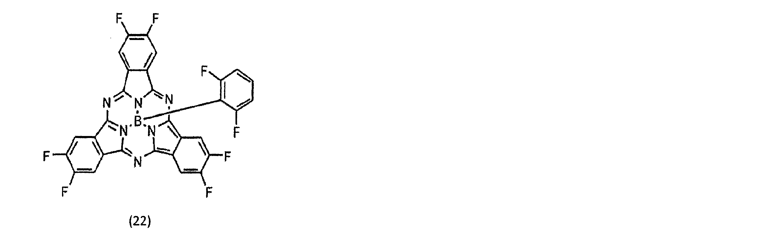


[外部量子効率の評価]
緑色LED光源からバンドパスフィルターを介して光電変換素子に照射される光の波長を560nm、光量を1.62μW/cm2とし、光電変換素子の電極間に印加されるバイアス電圧を半導体パラメータアナライザを用いて制御し、上部電極に対し、下部電極に印加する電圧を掃引することで、電流―電圧曲線を得た。バイアス電圧を-2.6Vとした場合の明電流値および暗電流値を計測し、EQEを算出した。 [Evaluation of external quantum efficiency]
The wavelength of light emitted from the green LED light source to the photoelectric conversion element via the band-pass filter is 560 nm, the light amount is 1.62 μW / cm 2, and the bias voltage applied between the electrodes of the photoelectric conversion element is determined by a semiconductor parameter analyzer. The current-voltage curve was obtained by sweeping the voltage applied to the lower electrode with respect to the upper electrode. The bright current value and the dark current value when the bias voltage was -2.6 V were measured, and the EQE was calculated.
EQEの算出結果を表7に示す。実験例4のEQEを1.0とすると、実験例5~7は同等の良好な特性が得られた。一方、実験例8,9は良好な特性が得られなかった。
Table 7 shows the calculation results of EQE. Assuming that the EQE of Experimental Example 4 was 1.0, Experimental Examples 5 to 7 had the same good characteristics. On the other hand, in Experimental Examples 8 and 9, good characteristics were not obtained.

[PL測定]
実験例4~7に対してPL測定を行った。PL測定は、ラマン分光装置を用いて、励起に波長532nmのYAGレーザーを使用し、測定波長範囲は500nm以上1000nm以下とした。レーザーを強く照射すると有機膜にダメージを与えるため、発光スペクトルが確認できる最小限の光量にNDフィルタを用いて調整し、ITOの上から光照射することにより測定した。 [PL measurement]
PL measurements were performed on Experimental Examples 4 to 7. In the PL measurement, a YAG laser having a wavelength of 532 nm was used for excitation using a Raman spectrometer, and the measurement wavelength range was 500 nm or more and 1000 nm or less. Since the organic film is damaged by strong laser irradiation, the light intensity was adjusted by using an ND filter to a minimum light amount at which the emission spectrum could be confirmed, and the measurement was performed by irradiating light from above the ITO.
図18に、実験例4~7の活性層で取得したPLスペクトルを示し、図19に、実験例8、9の活性層で取得したPLスペクトルを示す。実験例4~9に含まれる第3有機半導体材料43は、500nm以上600nm以下に可視域吸収帯を有するため、PL測定の励起波長は、この吸収帯の波長である532nmとした。
FIG. 18 shows PL spectra obtained from the active layers of Experimental Examples 4 to 7, and FIG. 19 shows PL spectra obtained from the active layers of Experimental Examples 8 and 9. Since the third organic semiconductor material 43 included in Experimental Examples 4 to 9 has a visible absorption band at 500 nm or more and 600 nm or less, the excitation wavelength of the PL measurement was 532 nm, which is the wavelength of this absorption band.
図18に示すように、実験例4~7では520nm以上580nm以下の波長領域に第3有機半導体材料43の発光ピークが観測されず、第2有機半導体材料42として用いたフラーレンの発光ピークのみが715nmを極大波長とする領域に観測されている。よって、実験例4~7では、第2有機半導体材料42と第3有機半導体材料43が均一な相溶状態を形成していると判断できる。
As shown in FIG. 18, in Experimental Examples 4 to 7, no emission peak of the third organic semiconductor material 43 was observed in the wavelength region of 520 nm to 580 nm, and only the emission peak of fullerene used as the second organic semiconductor material 42 was observed. It is observed in the region where the maximum wavelength is 715 nm. Therefore, in Experimental Examples 4 to 7, it can be determined that the second organic semiconductor material 42 and the third organic semiconductor material 43 form a uniform compatible state.
図19に示すように、実験例8,9では、520nm以上580nm以下の波長領域に第3有機半導体材料43の発光ピークが観測される。このため、実験例8,9では、第3有機半導体材料43と第2有機半導体材料42が十分に相溶していないことが推測される。
で は As shown in FIG. 19, in Experimental Examples 8 and 9, the emission peak of the third organic semiconductor material 43 is observed in the wavelength range of 520 nm to 580 nm. Therefore, in Experimental Examples 8 and 9, it is presumed that the third organic semiconductor material 43 and the second organic semiconductor material 42 are not sufficiently compatible.
実際に、前述した方法でA/Bを算出した結果を表8に示す。実験例4~7では、A/B<0.1を満たすため、第2ドメイン17Bを構成する第2有機半導体材料42と第3有機半導体材料43が均一に相溶した状態を形成していると判断できる。
表 Table 8 shows the result of actually calculating A / B by the method described above. In Experimental Examples 4 to 7, in order to satisfy A / B <0.1, a state in which the second organic semiconductor material 42 and the third organic semiconductor material 43 forming the second domain 17B are uniformly dissolved is formed. Can be determined.

次に第1有機半導体材料41について述べる。電子供与性を有する第1有機半導体材料41は、第1ドメイン17Aとして自己ドメインを形成することで、正孔輸送パスを形成できると考えられる。ただし、第1ドメイン17Aの結晶粒径(ドメインサイズ)が大きくなりすぎると励起子の電荷分離効率が低下するため、第1ドメイン17Aの結晶粒径は20nm以下であることが好ましい。結晶粒径の確認は、第1有機半導体材料が結晶性であれば、X線回折法による結晶粒径の算出が有効である。
Next, the first organic semiconductor material 41 will be described. It is considered that the first organic semiconductor material 41 having an electron donating property can form a hole transport path by forming a self-domain as the first domain 17A. However, if the crystal grain size (domain size) of the first domain 17A is too large, the charge separation efficiency of excitons decreases, so that the crystal grain size of the first domain 17A is preferably 20 nm or less. In order to confirm the crystal grain size, if the first organic semiconductor material is crystalline, the calculation of the crystal grain size by the X-ray diffraction method is effective.
図20に、実験例6の活性層で測定したX線回折スペクトルを示す。X線源はCuKαとした。ブラッグ角19.2°付近に観測される第1有機半導体材料41由来の回折ピークから、結晶粒径は、12.9nmと算出された。結晶粒径は、PearsonVII関数を用いて、ブラッグ角19.2°付近に観測される第1有機半導体材料41由来の回折ピークをフィッティングし、その半値幅を求め、シェラーの式に代入することで求めた。その際、シェラー定数Kは0.94を用いた。もしくは、透過型電子顕微鏡(TEM)観察により、結晶ドメインの分散状態を確認してもよい。
FIG. 20 shows an X-ray diffraction spectrum measured on the active layer of Experimental Example 6. The X-ray source was CuKα. From the diffraction peak derived from the first organic semiconductor material 41 observed near the Bragg angle of 19.2 °, the crystal grain size was calculated to be 12.9 nm. The crystal grain size is obtained by fitting the diffraction peak derived from the first organic semiconductor material 41 observed near the Bragg angle of 19.2 ° using the Pearson VII function, obtaining the half-value width thereof, and substituting it into Scherrer's equation. I asked. At that time, the Scherrer constant K used was 0.94. Alternatively, the dispersion state of the crystal domains may be confirmed by observation with a transmission electron microscope (TEM).
実験6と同様に、実験例4,5,7,9についてもXRDにより第1ドメイン17Aの結晶粒径を算出した。第1ドメイン17Aの結晶粒径の算出結果を表9に示す。
同 様 Similar to Experiment 6, the crystal grain size of the first domain 17A was calculated by XRD also for Experimental Examples 4, 5, 7, and 9. Table 9 shows the calculation results of the crystal grain size of the first domain 17A.

表9に示すように実験例4~7のように第1ドメイン17Aの結晶粒径が11.5以上12.9nm以下の場合に、表7に示すように良好なEQEが得られることが分かった。
As shown in Table 9, when the crystal grain size of the first domain 17A is 11.5 or more and 12.9 nm or less as in Experimental Examples 4 to 7, it is found that good EQE is obtained as shown in Table 7. Was.
(第5実施形態)
第5実施形態に係る光電変換素子10も、図1に示した断面構造を有し、第1~第4実施形態に係る光電変換素子の構造と共通する。しかしながら、第5実施形態に係る光電変換素子10は、有機光電変換層17の構成が第1~第4実施形態と相違する。以下では有機光電変換層17の構成に着目して説明し、第1~第4実施形態との共通部分の説明を省略する。 (Fifth embodiment)
Thephotoelectric conversion element 10 according to the fifth embodiment also has the cross-sectional structure shown in FIG. 1, and is common to the structures of the photoelectric conversion elements according to the first to fourth embodiments. However, the photoelectric conversion element 10 according to the fifth embodiment is different from the first to fourth embodiments in the configuration of the organic photoelectric conversion layer 17. The following description focuses on the configuration of the organic photoelectric conversion layer 17, and a description of common parts with the first to fourth embodiments will be omitted.
第5実施形態に係る光電変換素子10も、図1に示した断面構造を有し、第1~第4実施形態に係る光電変換素子の構造と共通する。しかしながら、第5実施形態に係る光電変換素子10は、有機光電変換層17の構成が第1~第4実施形態と相違する。以下では有機光電変換層17の構成に着目して説明し、第1~第4実施形態との共通部分の説明を省略する。 (Fifth embodiment)
The
第3実施形態で既に述べた通り、固体撮像装置の画素等として用いる光電変換素子においては、外部量子効率(EQE)の改善が求められている。そこで、第5実施形態では、EQEを改善することができる光電変換素子を提供する。
As already described in the third embodiment, the photoelectric conversion element used as a pixel or the like of the solid-state imaging device is required to have an improved external quantum efficiency (EQE). Therefore, in the fifth embodiment, a photoelectric conversion element capable of improving the EQE is provided.
第5実施形態に係る光電変換素子10は、図1に模式的に示すように、対向配置された下部電極(第1電極)15aおよび上部電極(第2電極)18と、下部電極15aおよび上部電極18との間に設けられた有機光電変換層17とを備える。上部電極18と有機光電変換層17との間には電子輸送層17aが設けられている。下部電極15aと有機光電変換層17との間には正孔輸送層17bが設けられている。
As schematically shown in FIG. 1, the photoelectric conversion element 10 according to the fifth embodiment includes a lower electrode (first electrode) 15a and an upper electrode (second electrode) 18 opposed to each other, and a lower electrode 15a and an upper electrode. And an organic photoelectric conversion layer 17 provided between the electrode 18. An electron transport layer 17a is provided between the upper electrode 18 and the organic photoelectric conversion layer 17. A hole transport layer 17b is provided between the lower electrode 15a and the organic photoelectric conversion layer 17.
有機光電変換層17は、少なくともフラーレンを含む2種類以上の有機半導体材料で構成されている。例えば、有機光電変換層17は、互いに異なる母骨格を有する第1有機半導体材料及び第2有機半導体材料で構成されていてよい。第1有機半導体材料は電子供与性を有し、第2有機半導体材料は電子受容性を有する。第1有機半導体材料は、p型半導体有機材料で構成される。p型半導体有機材料は、相対的に電子供与体(ドナー)として機能する。第2有機半導体材料は、n型半導体有機材料で構成される。n型半導体有機材料は、相対的に電子受容体(アクセプタ)として機能する。有機光電変換層17を構成するp型有機半導体材料およびn型有機半導体材料の混合割合は、例えばp型有機半導体材料が30質量%、n型有機半導体材料が70質量%程度であってよく、これに限定されない。
The organic photoelectric conversion layer 17 is composed of two or more organic semiconductor materials containing at least fullerene. For example, the organic photoelectric conversion layer 17 may be composed of a first organic semiconductor material and a second organic semiconductor material having mutually different mother skeletons. The first organic semiconductor material has an electron donating property, and the second organic semiconductor material has an electron accepting property. The first organic semiconductor material is composed of a p-type semiconductor organic material. The p-type semiconductor organic material relatively functions as an electron donor (donor). The second organic semiconductor material is composed of an n-type semiconductor organic material. The n-type semiconductor organic material relatively functions as an electron acceptor (acceptor). The mixing ratio of the p-type organic semiconductor material and the n-type organic semiconductor material constituting the organic photoelectric conversion layer 17 may be, for example, about 30% by mass of the p-type organic semiconductor material and about 70% by mass of the n-type organic semiconductor material, It is not limited to this.
有機光電変換層17に含まれる第1有機半導体材料および第2有機半導体材料としては、例えば、キナクリドン、塩素化ホウ素サブフタロシアニン、ペンタセン、ベンゾチエノベンゾチオフェン、フラーレンおよびそれらの誘導体等の有機半導体材料を2種以上組み合わせて構成されている。上記有機半導体材料は、その組み合わせによってp型半導体またはn型半導体として機能する。なお、有機光電変換層17に含まれる第1有機半導体材料および第2有機半導体材料としては更に、例えば、ナフタレン、アントラセン、フェナントレン、テトラセン、ピレン、ペリレン、およびフルオランテンあるいはそれらの誘導体のうちのいずれか1種が好適に用いられる。あるいは、フェニレンビニレン、フルオレン、カルバゾール、インドール、ピレン、ピロール、ピコリン、チオフェン、アセチレン、ジアセチレン等の重合体やそれらの誘導体を用いてもよい。第5実施形態では、例えば第2有機半導体材料を構成するn型半導体材料がフラーレンまたはフラーレン誘導体であってよい。
Examples of the first organic semiconductor material and the second organic semiconductor material included in the organic photoelectric conversion layer 17 include organic semiconductor materials such as quinacridone, boron chlorinated subphthalocyanine, pentacene, benzothienobenzothiophene, fullerene, and derivatives thereof. It is configured by combining two or more types. The organic semiconductor material functions as a p-type semiconductor or an n-type semiconductor depending on the combination. The first organic semiconductor material and the second organic semiconductor material included in the organic photoelectric conversion layer 17 further include, for example, naphthalene, anthracene, phenanthrene, tetracene, pyrene, perylene, and fluoranthene, or any of derivatives thereof. One type is suitably used. Alternatively, a polymer such as phenylenevinylene, fluorene, carbazole, indole, pyrene, pyrrole, picoline, thiophene, acetylene, diacetylene, or a derivative thereof may be used. In the fifth embodiment, for example, the n-type semiconductor material forming the second organic semiconductor material may be fullerene or a fullerene derivative.
有機光電変換層17が第1有機半導体材料及び第2有機半導体材料で構成されている場合、第2有機半導体材料を構成するフラーレンまたはフラーレン誘導体の自己凝集が抑制され、第1有機半導体材料および第2有機半導体材料が均一に相溶した状態となることが好ましい。第1有機半導体材料および第2有機半導体材料が均一に相溶した状態とは、第1有機半導体材料と第2有機半導体材料が自己会合や自己凝集を形成せず、均一に混ざり合った一相となる状態を意味する。
When the organic photoelectric conversion layer 17 is composed of the first organic semiconductor material and the second organic semiconductor material, self-aggregation of fullerene or fullerene derivative constituting the second organic semiconductor material is suppressed, and the first organic semiconductor material and It is preferable that the two organic semiconductor materials be in a state of being uniformly dissolved. The state in which the first organic semiconductor material and the second organic semiconductor material are uniformly compatible means that the first organic semiconductor material and the second organic semiconductor material do not form self-association or self-aggregation, but are uniformly mixed. Means the following condition.
また、有機光電変換層17は、第1有機半導体材料及び第2有機半導体材料に加えて、第1有機半導体材料及び第2有機半導体材料と異なる母骨格を有する第3有機半導体材料を含んでもよい。第3有機半導体材料は光を吸収して励起する色素材料である。例えば、有機光電変換層17を構成する第1有機半導体材料、第2有機半導体材料、第3有機半導体材料の混合割合として、第1有機半導体材料が30質量%、第2有機半導体材料が30質量%、第3有機半導体材料が40質量%を例示するが、この値に限定するものではない。
In addition, the organic photoelectric conversion layer 17 may include a third organic semiconductor material having a different mother skeleton from the first organic semiconductor material and the second organic semiconductor material, in addition to the first organic semiconductor material and the second organic semiconductor material. . The third organic semiconductor material is a dye material that absorbs and excites light. For example, as a mixing ratio of the first organic semiconductor material, the second organic semiconductor material, and the third organic semiconductor material constituting the organic photoelectric conversion layer 17, the first organic semiconductor material is 30% by mass, and the second organic semiconductor material is 30% by mass. %, And the third organic semiconductor material is 40% by mass, but is not limited to these values.
第3有機半導体材料43としては、例えば、金属錯体色素材料、シアニン系色素材料、メロシアニン系色素材料、フェニルキサンテン系色素材料、トリフェニルメタン系色素材料、ロダシアニン系色素材料、キサンテン系色素材料、大環状アザアヌレン系色素材料、アズレン系色素材料、ナフトキノン、アントラキノン系色素材料、アントラセンおよびピレン等の縮合多環芳香族および芳香環あるいは複素環化合物が縮合した鎖状化合物、または、スクアリリウム基およびクロコニツクメチン基を結合鎖として持つキノリン、ベンゾチアゾール、ベンゾオキサゾール等の二つの含窒素複素環、または、スクアリリウム基およびクロコニツクメチン基により結合したシアニン系類似の色素材料等を好ましく用いることができる。なお、上記金属錯体色素材料としては、ジチオール金属錯体系色素材料、金属フタロシアニン色素材料、金属ポルフィリン色素材料、またはルテニウム錯体色素材料が好ましいが、これに限定されるものではない。
Examples of the third organic semiconductor material 43 include a metal complex dye material, a cyanine dye material, a merocyanine dye material, a phenylxanthene dye material, a triphenylmethane dye material, a rhodacyanine dye material, a xanthene dye material, Cyclic azaannulene dye material, azulene dye material, naphthoquinone, anthraquinone dye material, condensed polycyclic aromatic and aromatic compounds such as anthracene and pyrene or a chain compound condensed with a heterocyclic compound, or a squarylium group and croconitcumethine Two nitrogen-containing heterocycles such as quinoline, benzothiazole, and benzoxazole having a group as a bonding chain, or a cyanine-like dye material bonded by a squarylium group and a croconite methine group can be preferably used. The metal complex dye material is preferably a dithiol metal complex dye material, a metal phthalocyanine dye material, a metal porphyrin dye material, or a ruthenium complex dye material, but is not limited thereto.
有機光電変換層17が第1有機半導体材料、第2有機半導体材料及び第3有機半導体材料からなる場合には、第4実施形態で既に述べた通りであるが、図12に模式的に示すように、第1有機半導体材料41のみで構成された第1ドメイン17Aと、第2有機半導体材料42と第3有機半導体材料43が均一に相溶した第2ドメイン17Bを有していてもよい。そして、図14に示すように、第2有機半導体材料42と第3有機半導体材料43は、分子レベルで均一に相溶(混和)しており、各第2有機半導体材料42及び第3有機半導体材料4の自己会合や自己凝集が抑制されている。第2ドメイン17B内において、第2有機半導体材料42と第3有機半導体材料43が均一に相溶した状態とは、図14Aに模式的に示すように、第2有機半導体材料42と第3有機半導体材料43が自己会合や自己凝集を形成せず、均一に混ざり合った一相となる状態を意味する。
When the organic photoelectric conversion layer 17 is made of the first organic semiconductor material, the second organic semiconductor material, and the third organic semiconductor material, it is as already described in the fourth embodiment, but as schematically shown in FIG. In addition, a first domain 17A composed of only the first organic semiconductor material 41 and a second domain 17B in which the second organic semiconductor material 42 and the third organic semiconductor material 43 are uniformly mixed may be provided. Then, as shown in FIG. 14, the second organic semiconductor material 42 and the third organic semiconductor material 43 are uniformly compatible (mixed) at the molecular level, and each of the second organic semiconductor material 42 and the third organic semiconductor material 43 Self-association and self-aggregation of the material 4 are suppressed. In the second domain 17B, the state in which the second organic semiconductor material 42 and the third organic semiconductor material 43 are uniformly compatible means that the second organic semiconductor material 42 and the third organic semiconductor material 43 are, as schematically shown in FIG. This refers to a state in which the semiconductor material 43 does not form self-association or self-aggregation, but forms a uniformly mixed phase.
第1ドメイン17Aを構成する第1有機半導体材料41は、結晶性であることが望ましく、結晶微粒子状の第1ドメイン17Aがホール輸送パスを形成する。一方、第2ドメイン17Bを構成する第2有機半導体材料42と第3有機半導体材料43は、分子レベルで均一に相溶(混和)しており、各材料の自己会合や自己凝集が抑制されている。第3有機半導体材料43が自己会合や自己凝集を形成すると、その会合体により所望の吸収と異なる吸収が発生したり、励起子の電荷分離効率が低下したりすることが考えられる。第2有機半導体材料42が自己会合や自己凝集を形成すると、分散した状態と異なるエネルギー準位が発生する。これは、トラップやエネルギー移動の阻害要因となり得る。そこで、図14Aに示すように第2有機半導体材料42と第3有機半導体材料43を分子レベルで均一に相溶させることで、これらの不利益を抑制することができる。更に、第2有機半導体材料42同士の分子間距離も一定に保たれているため、図13に示すように、電子輸送パスも確保される。このような構造をとることで、色素材料をドナーとアクセプタの接合界面に偏析させたり、有機半導体材料中に分散させたりする場合と比較して、第3有機半導体材料43の配合量を制限する必要がなくなる。第3有機半導体材料43は、光吸収を増感させる効果があるため、第2有機半導体材料42の配合量よりも多くし、光吸収効率を高めることが望ましい。
第 The first organic semiconductor material 41 constituting the first domain 17A is preferably crystalline, and the first domain 17A in the form of fine crystalline particles forms a hole transport path. On the other hand, the second organic semiconductor material 42 and the third organic semiconductor material 43 constituting the second domain 17B are uniformly compatible (mixed) at the molecular level, and self-association and self-aggregation of each material are suppressed. I have. When the third organic semiconductor material 43 forms self-association or self-aggregation, it is conceivable that absorption different from desired absorption occurs due to the associated body, and the charge separation efficiency of excitons decreases. When the second organic semiconductor material 42 forms self-association or self-aggregation, an energy level different from the dispersed state is generated. This can be a hindrance to traps and energy transfer. Therefore, as shown in FIG. 14A, these disadvantages can be suppressed by uniformly dissolving the second organic semiconductor material 42 and the third organic semiconductor material 43 at the molecular level. Further, since the intermolecular distance between the second organic semiconductor materials 42 is kept constant, an electron transport path is also secured as shown in FIG. With such a structure, the amount of the third organic semiconductor material 43 is limited as compared with the case where the dye material is segregated at the junction interface between the donor and the acceptor or dispersed in the organic semiconductor material. Eliminates the need. Since the third organic semiconductor material 43 has an effect of sensitizing light absorption, it is desirable to increase the amount of the second organic semiconductor material 42 to increase the light absorption efficiency.
ここで、有機光電変換層17が第1有機半導体材料及び第2有機半導体材料の2種類で構成されており、第2有機半導体材料がフラーレンまたはフラーレン誘導体である場合の、フラーレンまたはフラーレン誘導体と第1有機半導体材料との相溶及び相互作用の状態、ならびに、有機光電変換層17が第1有機半導体材料、第2有機半導体材料および第3有機半導体材料の3種類で構成されており、第2有機半導体材料がフラーレンまたはフラーレン誘導体である場合の、フラーレンまたはフラーレン誘導体と第3有機半導体材料との相溶及び相互作用の状態は、有機光電変換層17中のフラーレンまたはフラーレン誘導体のエネルギーギャップを観測することで確認できるという知見を本発明者らは得た。
Here, when the organic photoelectric conversion layer 17 is composed of two kinds of the first organic semiconductor material and the second organic semiconductor material, and the second organic semiconductor material is a fullerene or a fullerene derivative, (1) the state of compatibility and interaction with the organic semiconductor material, and the organic photoelectric conversion layer 17 is composed of three types of first organic semiconductor material, second organic semiconductor material, and third organic semiconductor material; When the organic semiconductor material is a fullerene or a fullerene derivative, the state of compatibility and interaction between the fullerene or the fullerene derivative and the third organic semiconductor material is determined by observing the energy gap of the fullerene or the fullerene derivative in the organic photoelectric conversion layer 17. The present inventors have obtained the knowledge that this can be confirmed by performing the above.
即ち、本発明者らは、C60膜の結晶におけるエネルギーギャップEg(C60)は2.4eVであるのに対して、C60が相溶状態にある場合には、エネルギーギャップEg(C60)が2.6eV以上と大きくなることを確認した。更に、C60とp型半導体材料との相互作用、或いはC60と有機色素材料との相溶及び相互作用によってエネルギーギャップEg(C60)が2.8eV以上3.1eV以下と更に広がることを確認した。なお、3.1eVは、エネルギーギャップEg(C60)の原理的な最大値である。
That is, the present inventors have found that the energy gap Eg (C60) of the crystal of the C60 film is 2.4 eV, while the energy gap Eg (C60) is 2.40 eV when C60 is in a compatible state. It was confirmed to be as large as 6 eV or more. Further, it was confirmed that the energy gap Eg (C60) was further widened from 2.8 eV to 3.1 eV due to the interaction between C60 and the p-type semiconductor material or the compatibility and interaction between C60 and the organic dye material. Note that 3.1 eV is a theoretical maximum value of the energy gap Eg (C60).
有機光電変換層17中のフラーレンまたはフラーレン誘導体のエネルギーギャップは紫外光電子分光法(UPS)と逆光電子分光法(IPES)を組み合わせることで確認できる。即ち、紫外光電子分光法により測定されるフラーレンまたはフラーレン誘導体のHOMOのイオン化エネルギーを、HOMO由来のピーク立ち上がり部として求める。また、逆光電子分光法により測定されるフラーレンまたはフラーレン誘導体の電子親和力を、LUMO由来のピーク立ち上がり部として求める。そして、HOMO由来のピーク立ち上がり部と、LUMO由来のピーク立ち上がり部のエネルギー差を、エネルギーギャップとして求めることができる。
(4) The energy gap of the fullerene or the fullerene derivative in the organic photoelectric conversion layer 17 can be confirmed by combining ultraviolet photoelectron spectroscopy (UPS) and inverse photoelectron spectroscopy (IPES). That is, the ionization energy of HOMO of fullerene or a fullerene derivative measured by ultraviolet photoelectron spectroscopy is determined as a peak rising portion derived from HOMO. In addition, the electron affinity of fullerene or a fullerene derivative measured by inverse photoelectron spectroscopy is determined as a LUMO-derived peak rising portion. Then, the energy difference between the HOMO-derived peak rising portion and the LUMO-derived peak rising portion can be determined as the energy gap.
図21Aは、C60単膜に対して、紫外光電子分光法および逆光電子分光法により測定されたC60のスペクトルを示す。紫外光電子分光法により測定されたイオン化ポテンシャル(IP)が6.5eVであり、逆光電子分光法により測定された電子親和力(EA)が4.1eVである。紫外光電子分光法により測定されたHOMO由来のピーク立ち上がり部と、逆光電子分光法により測定されたLUMO由来のピーク立ち上がり部のエネルギー差であるエネルギーギャップEg(C60)は、2.4eVである。
FIG. 21A shows a spectrum of C60 measured by ultraviolet photoelectron spectroscopy and reverse photoelectron spectroscopy on a C60 single film. The ionization potential (IP) measured by ultraviolet photoelectron spectroscopy is 6.5 eV, and the electron affinity (EA) measured by reverse photoelectron spectroscopy is 4.1 eV. The energy gap Eg (C60), which is the energy difference between the HOMO-derived peak rising portion measured by ultraviolet photoelectron spectroscopy and the LUMO-derived peak rising portion measured by inverse photoelectron spectroscopy, is 2.4 eV.
図21Bは、B12:26F2:C60=4:4:2で構成する光電変換膜に対して、紫外光電子分光法および逆光電子分光法により測定されたC60のスペクトルを示す。紫外光電子分光法により測定されたイオン化ポテンシャル(IP)が6.7eVであり、逆光電子分光法により測定された電子親和力(EA)が3.7eVである。紫外光電子分光法により測定されたHOMO由来のピーク立ち上がり部と、逆光電子分光法により測定されたLUMO由来のピーク立ち上がり部のエネルギー差であるエネルギーギャップEg(C60)は、2.99eVとなり、図21AのC60単膜の場合よりも大きいことが分かる。
FIG. 21B shows a C60 spectrum of a photoelectric conversion film composed of B12: 26F2: C60 = 4: 4: 2 measured by ultraviolet photoelectron spectroscopy and inverse photoelectron spectroscopy. The ionization potential (IP) measured by ultraviolet photoelectron spectroscopy is 6.7 eV, and the electron affinity (EA) measured by reverse photoelectron spectroscopy is 3.7 eV. The energy gap Eg (C60), which is the energy difference between the HOMO-derived peak rising portion measured by ultraviolet photoelectron spectroscopy and the LUMO-derived peak rising portion measured by reverse photoelectron spectroscopy, was 2.99 eV, and FIG. 21A It can be seen that it is larger than the case of the C60 single film.
図22は、C60、色素及びHTMのLUMO準位及びHOMO準位を示す。C60のLUMO準位が破線で示す位置であり、エネルギーギャップEg(C60)が小さいと、トラップとなり、特性が悪化する場合がある。これに対して、C60のLUMO準位が実線で示す位置であり、エネルギーギャップEg(C60)が増大すると、トラップとなることを抑制できる。
FIG. 22 shows the LUMO and HOMO levels of C60, dye and HTM. If the LUMO level of C60 is the position indicated by the broken line and the energy gap Eg (C60) is small, it becomes a trap and the characteristics may deteriorate. On the other hand, when the LUMO level of C60 is the position indicated by the solid line and the energy gap Eg (C60) increases, it is possible to suppress the trap from becoming a trap.
このため、有機光電変換層17が第1有機半導体材料及び第2有機半導体材料の2種類で構成されており、第2有機半導体材料がフラーレンまたはフラーレン誘導体である場合に、有機光電変換層17中のフラーレンまたはフラーレン誘導体のエネルギーギャップの値が2.6eV以上であれば、フラーレンまたはフラーレン誘導体の自己凝集が抑制され、フラーレンまたはフラーレン誘導体と第1有機半導体材料とが相溶したことの判断指標となる。
For this reason, when the organic photoelectric conversion layer 17 is composed of two types of the first organic semiconductor material and the second organic semiconductor material, and the second organic semiconductor material is fullerene or a fullerene derivative, the organic photoelectric conversion layer 17 When the value of the energy gap of the fullerene or fullerene derivative is 2.6 eV or more, self-aggregation of the fullerene or fullerene derivative is suppressed, and a judgment index indicating that the fullerene or the fullerene derivative and the first organic semiconductor material are compatible with each other. Become.
また、有機光電変換層17が第1有機半導体材料、第2有機半導体材料および第3有機半導体材料の3種類で構成されており、第2有機半導体材料がフラーレンまたはフラーレン誘導体である場合には、有機光電変換層17中のフラーレンまたはフラーレン誘導体のエネルギーギャップの値が2.6eV以上であれば、フラーレンまたはフラーレン誘導体の自己凝集が抑制され、フラーレンまたはフラーレン誘導体と第3有機半導体材料とが相溶したことの判断指標となる。
Further, when the organic photoelectric conversion layer 17 is composed of three types of a first organic semiconductor material, a second organic semiconductor material, and a third organic semiconductor material, and the second organic semiconductor material is a fullerene or a fullerene derivative, When the value of the energy gap of the fullerene or the fullerene derivative in the organic photoelectric conversion layer 17 is 2.6 eV or more, self-aggregation of the fullerene or the fullerene derivative is suppressed, and the fullerene or the fullerene derivative is compatible with the third organic semiconductor material. It will be an indicator of what you have done.
以上説明したように、第5実施形態に係る光電変換素子10によれば、バルクヘテロ接合型の有機光電変換層17において、n型半導体材料であるC60のエネルギーギャップEg(C60)が2.6eV以上となるような構造、材料、成膜条件等を採用することにより、C60の自己凝集を抑制し、C60と有機色素材料、或いはC60とp型半導体材料とを相溶させることができるので、光吸収効率を向上させることができる。更に、C60のエネルギーギャップEg(C60)が2.8eV以上3.1eV以下となるような構造、材料、成膜条件等を採用することにより、C60の自己凝集をより抑制し、相溶性をより高めることができるので、光吸収効率をより向上させることができる。
As described above, according to the photoelectric conversion element 10 according to the fifth embodiment, the energy gap Eg (C60) of C60, which is an n-type semiconductor material, is 2.6 eV or more in the bulk heterojunction type organic photoelectric conversion layer 17. By adopting such a structure, material, film forming conditions, etc., self-aggregation of C60 can be suppressed, and C60 can be mixed with an organic dye material or C60 and a p-type semiconductor material. The absorption efficiency can be improved. Further, by adopting a structure, a material, film forming conditions, and the like such that the energy gap Eg (C60) of C60 becomes 2.8 eV or more and 3.1 eV or less, self-aggregation of C60 is further suppressed, and compatibility is further improved. Since it can be increased, the light absorption efficiency can be further improved.
<実施例>
[実験例10~14の試料作成方法]
実験例10の作製方法としては、石英基板上にスパッタリング装置を用いて厚さ100nmのITOを成膜し、フォトリソグラフィーとエッチングにより、ITO膜をパターニングし、ITO下部電極を形成した。この基板をUV/オゾン処理にて洗浄した後、基板を真空蒸着機に移し、1×10-5Pa以下に減圧された状態で、基板ホルダを回転させながら、抵抗加熱法によって有機材料の成膜を行った。はじめに電子ブロッキング層として、上記式(18)に示したHTM105を基板温度0℃にて10nm成膜し、次に基板温度40℃にて、第1有機半導体材料として上記式(19)に示したBP-rBDT、第2有機半導体材料としてC60、第3有機半導体材料43として上記式(17)に示したF6-SubPc-OPh2,6F2を成膜レート、それぞれ、0.50Å/秒、0.50Å/秒、0.25Å/秒で、混合層の厚さが230nmとなるように成膜した。最後に、正孔ブロッキング層として、上記式(20)に示したNDI-35を基板温度0℃にて10nm成膜した。続いて、スパッタリング装置に基板を移し、ITOを50nmの厚みで成膜し、上部電極を形成した。以上の作製方法により1mm×1mmの光電変換領域を有する光電変換素子を作製した。作製した素子は、N2雰囲気下で、150℃、210分アニールを行った。 <Example>
[Sample preparation method of Experimental Examples 10 to 14]
As a manufacturing method of Experimental Example 10, an ITO film having a thickness of 100 nm was formed on a quartz substrate by using a sputtering apparatus, and the ITO film was patterned by photolithography and etching to form an ITO lower electrode. After cleaning the substrate by UV / ozone treatment, the substrate is transferred to a vacuum evaporation machine, and the organic material is formed by a resistance heating method while rotating the substrate holder under a reduced pressure of 1 × 10 −5 Pa or less. The membrane was made. First, as an electron blocking layer, HTM105 represented by the above formula (18) was formed to a thickness of 10 nm at a substrate temperature of 0 ° C. Then, at a substrate temperature of 40 ° C., a first organic semiconductor material represented by the above formula (19) was formed. BP-rBDT, C60 as the second organic semiconductor material, and F6-SubPc-OPh2,6F2 represented by the above formula (17) as the thirdorganic semiconductor material 43, at a deposition rate of 0.50 ° / sec and 0.50 °, respectively. / Sec, at 0.25 ° / sec, so that the thickness of the mixed layer was 230 nm. Finally, as a hole blocking layer, NDI-35 represented by the above formula (20) was deposited to a thickness of 10 nm at a substrate temperature of 0 ° C. Subsequently, the substrate was transferred to a sputtering apparatus, and ITO was formed to a thickness of 50 nm to form an upper electrode. By the above manufacturing method, a photoelectric conversion element having a 1 mm × 1 mm photoelectric conversion region was manufactured. The fabricated device was annealed at 150 ° C. for 210 minutes in an N 2 atmosphere.
[実験例10~14の試料作成方法]
実験例10の作製方法としては、石英基板上にスパッタリング装置を用いて厚さ100nmのITOを成膜し、フォトリソグラフィーとエッチングにより、ITO膜をパターニングし、ITO下部電極を形成した。この基板をUV/オゾン処理にて洗浄した後、基板を真空蒸着機に移し、1×10-5Pa以下に減圧された状態で、基板ホルダを回転させながら、抵抗加熱法によって有機材料の成膜を行った。はじめに電子ブロッキング層として、上記式(18)に示したHTM105を基板温度0℃にて10nm成膜し、次に基板温度40℃にて、第1有機半導体材料として上記式(19)に示したBP-rBDT、第2有機半導体材料としてC60、第3有機半導体材料43として上記式(17)に示したF6-SubPc-OPh2,6F2を成膜レート、それぞれ、0.50Å/秒、0.50Å/秒、0.25Å/秒で、混合層の厚さが230nmとなるように成膜した。最後に、正孔ブロッキング層として、上記式(20)に示したNDI-35を基板温度0℃にて10nm成膜した。続いて、スパッタリング装置に基板を移し、ITOを50nmの厚みで成膜し、上部電極を形成した。以上の作製方法により1mm×1mmの光電変換領域を有する光電変換素子を作製した。作製した素子は、N2雰囲気下で、150℃、210分アニールを行った。 <Example>
[Sample preparation method of Experimental Examples 10 to 14]
As a manufacturing method of Experimental Example 10, an ITO film having a thickness of 100 nm was formed on a quartz substrate by using a sputtering apparatus, and the ITO film was patterned by photolithography and etching to form an ITO lower electrode. After cleaning the substrate by UV / ozone treatment, the substrate is transferred to a vacuum evaporation machine, and the organic material is formed by a resistance heating method while rotating the substrate holder under a reduced pressure of 1 × 10 −5 Pa or less. The membrane was made. First, as an electron blocking layer, HTM105 represented by the above formula (18) was formed to a thickness of 10 nm at a substrate temperature of 0 ° C. Then, at a substrate temperature of 40 ° C., a first organic semiconductor material represented by the above formula (19) was formed. BP-rBDT, C60 as the second organic semiconductor material, and F6-SubPc-OPh2,6F2 represented by the above formula (17) as the third
実験例11の作製方法としては、実験例10と同じ方法で、有機色素をF6-SubPc-OC6F5に変更して作製した。実験例12の作製方法としては、実験例10と同じ方法で、有機色素をZCl-Mesに変更して作製した。実験例13の作製方法としては、実験例10と同じ方法で、第1有機半導体材料をBTBT19に変更し、有機色素を用いずに作製した。実験例14の作製方法としては、実験例10と同じ方法で、有機色素をDu-Hに変更して作製した。
作 製 The method for producing Experimental Example 11 was the same as that in Experimental Example 10, except that the organic dye was changed to F6-SubPc-OC6F5. Experimental Example 12 was produced in the same manner as in Experimental Example 10, except that the organic dye was changed to ZCl-Mes. As a manufacturing method of Experimental Example 13, the first organic semiconductor material was changed to BTBT19 and manufactured without using an organic dye in the same manner as in Experimental Example 10. The production method of Experimental Example 14 was the same as that of Experimental Example 10, except that the organic dye was changed to Du-H.
[外部量子効率の評価]
緑色LED光源からバンドパスフィルターを介して光電変換素子に照射される光の波長を560nm、光量を1.62μW/cm2とし、光電変換素子の電極間に印加されるバイアス電圧を半導体パラメータアナライザを用いて制御し、上部電極に対し、下部電極に印加する電圧を掃引することで、電流―電圧曲線を得た。バイアス電圧を-2.6Vとした場合の明電流値および暗電流値を計測し、EQEを算出した。 [Evaluation of external quantum efficiency]
The wavelength of light emitted from the green LED light source to the photoelectric conversion element via the band-pass filter is 560 nm, the light amount is 1.62 μW / cm 2, and the bias voltage applied between the electrodes of the photoelectric conversion element is determined by a semiconductor parameter analyzer. The current-voltage curve was obtained by sweeping the voltage applied to the lower electrode with respect to the upper electrode. The bright current value and the dark current value when the bias voltage was -2.6 V were measured, and the EQE was calculated.
緑色LED光源からバンドパスフィルターを介して光電変換素子に照射される光の波長を560nm、光量を1.62μW/cm2とし、光電変換素子の電極間に印加されるバイアス電圧を半導体パラメータアナライザを用いて制御し、上部電極に対し、下部電極に印加する電圧を掃引することで、電流―電圧曲線を得た。バイアス電圧を-2.6Vとした場合の明電流値および暗電流値を計測し、EQEを算出した。 [Evaluation of external quantum efficiency]
The wavelength of light emitted from the green LED light source to the photoelectric conversion element via the band-pass filter is 560 nm, the light amount is 1.62 μW / cm 2, and the bias voltage applied between the electrodes of the photoelectric conversion element is determined by a semiconductor parameter analyzer. The current-voltage curve was obtained by sweeping the voltage applied to the lower electrode with respect to the upper electrode. The bright current value and the dark current value when the bias voltage was -2.6 V were measured, and the EQE was calculated.
[エネルギーギャップEg(C60)の測定]
エネルギーギャップEg(C60)の測定方法としては、紫外光電子分光(UPS)測定により検出されるC60のHOMO由来のピーク立ち上がり部と逆光電子分光(IPES)測定により検出されるC60のLUMO由来のピーク立ち上がり部とのエネルギー差を用いた。 [Measurement of energy gap Eg (C60)]
As a method of measuring the energy gap Eg (C60), a peak rising portion derived from HOMO of C60 detected by ultraviolet photoelectron spectroscopy (UPS) measurement and a peak rising portion derived from LUMO of C60 detected by inverse photoelectron spectroscopy (IPES) measurement The energy difference with the part was used.
各有機膜のUPS測定、及びIPES測定は、上部電極及び下部電極を剥離することで有機膜を露出させ、アルゴンガスクラスターイオン銃でエッチングすることで所望の膜を表面に露出させた。アルゴンガスクラスターイオン銃の条件は加速電圧2.5kV、ターゲット電流(資料電流)8nA、ラスターサイズ10×10mmとした。
U In the UPS measurement and IPES measurement of each organic film, the organic film was exposed by peeling the upper electrode and the lower electrode, and the desired film was exposed on the surface by etching with an argon gas cluster ion gun. The conditions of the argon gas cluster ion gun were an acceleration voltage of 2.5 kV, a target current (data current) of 8 nA, and a raster size of 10 × 10 mm.
C60のHOMO由来ピーク立ち上がり部、すなわち、C60のHOMOのイオン化エネルギーはUPS測定により測定できる。UPS測定の分析装置としては、アルバック・ファイ(ULVAC-PHI)株式会社製PHI 5000 VersaProbe IIを用いた。光源としてはHe放電管(励起光:HeIα、21.2eV)を用いた。分析時にはHeI共鳴線(21.2eV)を分析用サンプルに照射して、パスエネルギー1.18eVで光電子スペクトルを測定した。C60のHOMOのイオン化エネルギーとしてC60のHOMO由来のピークの立ち上がりのエネルギー位置を用いた。
立 ち 上 が り The rising part of the peak derived from HOMO of C60, that is, the ionization energy of HOMO of C60 can be measured by UPS measurement. As an analyzer for the UPS measurement, PHI 5000 VersaProbe II manufactured by ULVAC-PHI, Inc. was used. A He discharge tube (excitation light: HeIα, 21.2 eV) was used as a light source. At the time of analysis, a HeI resonance line (21.2 eV) was irradiated to the sample for analysis, and a photoelectron spectrum was measured at a pass energy of 1.18 eV. The energy position of the rising edge of the peak derived from HOMO of C60 was used as the ionization energy of HOMO of C60.
C60のLUMO由来のピーク立ち上がり部、すなわち、C60の電子親和力は低エネルギーIPES測定により測定できる。低エネルギーIPES測定の分析装置としては、アドキャップバキュームテクノロジー社製の低エネルギー逆光電子分光装置(LEIPS)を用いた。分析時には電子線を分析用サンプルに照射して、中心波長260nmのバンドパスフィルターを用いて逆光電子スペクトルを測定した。C60の電子親和力はスペクトルの立ち上がりのエネルギー位置を用いた。
ピ ー ク C60 LUMO-derived peak rising portion, that is, the electron affinity of C60 can be measured by low energy IPES measurement. As an analyzer for the low energy IPES measurement, a low energy inverse photoelectron spectrometer (LEIPS) manufactured by Adcap Vacuum Technology was used. At the time of analysis, the sample for analysis was irradiated with an electron beam, and a reverse photoelectron spectrum was measured using a band-pass filter having a center wavelength of 260 nm. The energy position of the rising edge of the spectrum was used for the electron affinity of C60.
C60のイオン化エネルギー(紫外光電子分光スペクトルのC60のHOMOピーク立ち上がりのエネルギー位置)とC60の電子親和力(逆光電子スペクトルのLUMOピーク立ち上がりのエネルギー位置)とのエネルギー差がC60のエネルギーギャップEg(C60)となる。
The energy difference between the ionization energy of C60 (the energy position of the rising HOMO peak of C60 in the ultraviolet photoelectron spectroscopy spectrum) and the electron affinity of C60 (the energy position of the rising LUMO peak of the inverse photoelectron spectrum) is equal to the energy gap Eg (C60) of the C60. Become.
実験例10~14についてのUPS測定及びIPES測定によるエネルギーギャップEg(C60)並びにEQEの測定結果を表10に示す。
Table 10 shows the measurement results of the energy gap Eg (C60) and the EQE by the UPS measurement and the IPES measurement for Experimental Examples 10 to 14.

表10に示すように、実験例14ではEg(C60)が2.6eV未満となり、C60が凝集している状態となり、良好なEQEが得られなかった。一方、実験例10~13では、Eg(C60)が2.6eV以上3.1eV以下となり、C60が第1有機半導体又は有機色素と相溶および相互作用し、良好なEQEが得られた。更に、実験例10,11では、Eg(C60)が2.8eV以上3.1eV以下となり、実験例12,13よりも更に良好なEQEが得られた。このように、Eg(C60)は2.6eV以上3.1eV以下が好ましく、更には2.8eV以上3.1eV以下がより好ましい。
As shown in Table 10, in Experimental Example 14, Eg (C60) was less than 2.6 eV, and C60 was in an agglomerated state, and good EQE was not obtained. On the other hand, in Experimental Examples 10 to 13, Eg (C60) was 2.6 eV or more and 3.1 eV or less, and C60 was compatible and interacted with the first organic semiconductor or the organic dye, and a good EQE was obtained. Further, in Experimental Examples 10 and 11, the Eg (C60) was 2.8 eV or more and 3.1 eV or less, and a better EQE than in Experimental Examples 12 and 13 was obtained. Thus, Eg (C60) is preferably 2.6 eV or more and 3.1 eV or less, and more preferably 2.8 eV or more and 3.1 eV or less.
(第1適用例)
第1~第5実施形態に係る光電変換素子10をそれぞれ画素として用いて、図23に示すように固体撮像装置1を構成することができる。この固体撮像装置1は、CMOSイメージセンサであり、半導体基板11上に、撮像エリアとしての画素領域4を有すると共に、この画素領域4の周辺領域に、例えば、垂直駆動回路5、カラム選択回路6、水平駆動回路7、出力回路8および制御回路9からなる周辺回路部(5,6,7,8,9)を有する。 (First application example)
Using thephotoelectric conversion elements 10 according to the first to fifth embodiments as pixels, a solid-state imaging device 1 can be configured as shown in FIG. The solid-state imaging device 1 is a CMOS image sensor, has a pixel region 4 as an imaging area on a semiconductor substrate 11, and has, for example, a vertical drive circuit 5, a column selection circuit 6 in a peripheral region of the pixel region 4. , A horizontal drive circuit 7, an output circuit 8, and a control circuit 9 (5, 6, 7, 8, 9).
第1~第5実施形態に係る光電変換素子10をそれぞれ画素として用いて、図23に示すように固体撮像装置1を構成することができる。この固体撮像装置1は、CMOSイメージセンサであり、半導体基板11上に、撮像エリアとしての画素領域4を有すると共に、この画素領域4の周辺領域に、例えば、垂直駆動回路5、カラム選択回路6、水平駆動回路7、出力回路8および制御回路9からなる周辺回路部(5,6,7,8,9)を有する。 (First application example)
Using the
画素領域4は、例えば、行列状に2次元配置された複数の単位画素3(光電変換素子10に相当)を有する。この単位画素3には、例えば、画素行ごとに画素駆動線L1(具体的には行選択線およびリセット制御線)が配線され、画素列ごとに垂直信号線L2が配線されている。画素駆動線L1は、画素からの信号読み出しのための駆動信号を伝送する。画素駆動線L1の一端は、垂直駆動回路5の各行に対応した出力端に接続されている。
The pixel region 4 has, for example, a plurality of unit pixels 3 (corresponding to the photoelectric conversion elements 10) two-dimensionally arranged in a matrix. In the unit pixel 3, for example, a pixel drive line L1 (specifically, a row selection line and a reset control line) is wired for each pixel row, and a vertical signal line L2 is wired for each pixel column. The pixel drive line L1 transmits a drive signal for reading a signal from a pixel. One end of the pixel drive line L1 is connected to an output end corresponding to each row of the vertical drive circuit 5.
垂直駆動回路5は、シフトレジスタやアドレスデコーダ等によって構成される。垂直駆動回路5は、画素領域4の各画素3を、例えば、行単位で駆動する。垂直駆動回路5によって選択走査された画素行の各画素3から出力される信号は、垂直信号線L2の各々を通してカラム選択回路6に供給される。カラム選択回路6は、垂直信号線L2ごとに設けられたアンプや水平選択スイッチ等によって構成されている。
(4) The vertical drive circuit 5 includes a shift register, an address decoder, and the like. The vertical drive circuit 5 drives each pixel 3 of the pixel region 4 in, for example, a row unit. A signal output from each pixel 3 of the pixel row selectively scanned by the vertical driving circuit 5 is supplied to the column selection circuit 6 through each of the vertical signal lines L2. The column selection circuit 6 includes an amplifier, a horizontal selection switch, and the like provided for each vertical signal line L2.
水平駆動回路7は、シフトレジスタやアドレスデコーダ等によって構成される。水平駆動回路7は、カラム選択回路6の各水平選択スイッチを走査しつつ順番に駆動する。この水平駆動回路7による選択走査により、垂直信号線L2の各々を通して伝送される各画素の信号が順番に水平信号線L3に出力され、当該水平信号線L3を通して半導体基板11の外部へ伝送される。
The horizontal drive circuit 7 includes a shift register, an address decoder, and the like. The horizontal drive circuit 7 sequentially drives the horizontal selection switches of the column selection circuit 6 while scanning them. By the selective scanning by the horizontal drive circuit 7, the signal of each pixel transmitted through each of the vertical signal lines L2 is sequentially output to the horizontal signal line L3, and transmitted to the outside of the semiconductor substrate 11 through the horizontal signal line L3. .
垂直駆動回路5、カラム選択回路6、水平駆動回路7および水平信号線L3からなる回路部分は、半導体基板11上に形成されていてもよく、あるいは外部制御ICに配設されたものであってもよい。また、それらの回路部分は、ケーブル等により接続された他の基板に形成されていてもよい。
The circuit portion including the vertical drive circuit 5, the column selection circuit 6, the horizontal drive circuit 7, and the horizontal signal line L3 may be formed on the semiconductor substrate 11, or may be provided on an external control IC. Is also good. Further, those circuit portions may be formed on another substrate connected by a cable or the like.
制御回路9は、半導体基板11の外部から与えられるクロックや、動作モードを指令するデータ等を受け取り、また、固体撮像装置1の内部情報等のデータを出力する。制御回路9はさらに、各種のタイミング信号を生成するタイミングジェネレータを有し、当該タイミングジェネレータで生成された各種のタイミング信号を基に垂直駆動回路5、カラム選択回路6および水平駆動回路7等の周辺回路の駆動制御を行う。
The control circuit 9 receives a clock supplied from outside the semiconductor substrate 11, data for instructing an operation mode, and the like, and outputs data such as internal information of the solid-state imaging device 1. The control circuit 9 further has a timing generator for generating various timing signals, and the peripheral circuits of the vertical drive circuit 5, the column selection circuit 6, the horizontal drive circuit 7 and the like are based on the various timing signals generated by the timing generator. Performs circuit drive control.
(第2適用例)
上記第1適用例に係る固体撮像装置1は、例えば、デジタルスチルカメラやビデオカメラ等のカメラシステムや、撮像機能を有する携帯電話等、撮像機能を備えたあらゆるタイプの電子機器に適用することができる。例えば、図24に示すように、第2適用例としての電子機器2(カメラ)の概略構成を示す。この電子機器2は、例えば、静止画または動画を撮影可能なビデオカメラであり、固体撮像装置1と、光学系(光学レンズ)201と、シャッタ装置202と、固体撮像装置1およびシャッタ装置202を駆動する駆動部204と、信号処理部203とを有する。光学系201は、被写体からの像光(入射光)を固体撮像装置1の画素領域4へ導く。この光学系201は、複数の光学レンズから構成されていてもよい。シャッタ装置202は、固体撮像装置1への光照射期間および遮光期間を制御する。駆動部204は、固体撮像装置1の転送動作およびシャッタ装置202のシャッタ動作を制御する。信号処理部203は、固体撮像装置1から出力された信号に対し、各種の信号処理を行う。信号処理後の映像信号は、メモリ等の記憶媒体に記憶されるか、あるいは、モニタ等に出力される。 (Second application example)
The solid-state imaging device 1 according to the first application example can be applied to all types of electronic devices having an imaging function, such as a camera system such as a digital still camera and a video camera, and a mobile phone having an imaging function. it can. For example, as shown in FIG. 24, a schematic configuration of an electronic device 2 (camera) as a second application example is shown. The electronic device 2 is, for example, a video camera capable of shooting a still image or a moving image, and includes a solid-state imaging device 1, an optical system (optical lens) 201, a shutter device 202, and the solid-state imaging device 1 and the shutter device 202. It has a driving unit 204 for driving and a signal processing unit 203. The optical system 201 guides image light (incident light) from a subject to the pixel region 4 of the solid-state imaging device 1. This optical system 201 may be composed of a plurality of optical lenses. The shutter device 202 controls a light irradiation period and a light blocking period to the solid-state imaging device 1. The drive unit 204 controls the transfer operation of the solid-state imaging device 1 and the shutter operation of the shutter device 202. The signal processing unit 203 performs various kinds of signal processing on the signal output from the solid-state imaging device 1. The video signal after the signal processing is stored in a storage medium such as a memory or output to a monitor or the like.
上記第1適用例に係る固体撮像装置1は、例えば、デジタルスチルカメラやビデオカメラ等のカメラシステムや、撮像機能を有する携帯電話等、撮像機能を備えたあらゆるタイプの電子機器に適用することができる。例えば、図24に示すように、第2適用例としての電子機器2(カメラ)の概略構成を示す。この電子機器2は、例えば、静止画または動画を撮影可能なビデオカメラであり、固体撮像装置1と、光学系(光学レンズ)201と、シャッタ装置202と、固体撮像装置1およびシャッタ装置202を駆動する駆動部204と、信号処理部203とを有する。光学系201は、被写体からの像光(入射光)を固体撮像装置1の画素領域4へ導く。この光学系201は、複数の光学レンズから構成されていてもよい。シャッタ装置202は、固体撮像装置1への光照射期間および遮光期間を制御する。駆動部204は、固体撮像装置1の転送動作およびシャッタ装置202のシャッタ動作を制御する。信号処理部203は、固体撮像装置1から出力された信号に対し、各種の信号処理を行う。信号処理後の映像信号は、メモリ等の記憶媒体に記憶されるか、あるいは、モニタ等に出力される。 (Second application example)
The solid-
(第3適用例)
本開示に係る技術は、様々な製品へ応用することができる。例えば、本開示に係る技術は、自動車、電気自動車、ハイブリッド電気自動車、自動二輪車、自転車、パーソナルモビリティ、飛行機、ドローン、船舶、ロボット、建設機械、農業機械(トラクター)などのいずれかの種類の移動体に搭載される装置として実現されてもよい。 (Third application example)
The technology according to the present disclosure can be applied to various products. For example, the technology according to the present disclosure may be applied to any type of transportation such as an automobile, an electric vehicle, a hybrid electric vehicle, a motorcycle, a bicycle, a personal mobility, an airplane, a drone, a ship, a robot, a construction machine, an agricultural machine (tractor), and the like. It may be realized as a device mounted on the body.
図25は、本開示に係る技術が適用され得る移動体制御システムの一例である車両制御システム7000の概略的な構成例を示すブロック図である。車両制御システム7000は、通信ネットワーク7010を介して接続された複数の電子制御ユニットを備える。図25に示した例では、車両制御システム7000は、駆動系制御ユニット7100、ボディ系制御ユニット7200、バッテリ制御ユニット7300、車外情報検出ユニット7400、車内情報検出ユニット7500、及び統合制御ユニット7600を備える。これらの複数の制御ユニットを接続する通信ネットワーク7010は、例えば、CAN(Controller Area Network)、LIN(Local Interconnect Network)、LAN(Local Area Network)又はFlexRay(登録商標)等の任意の規格に準拠した車載通信ネットワークであってよい。
FIG. 25 is a block diagram illustrating a schematic configuration example of a vehicle control system 7000 which is an example of a mobile object control system to which the technology according to the present disclosure can be applied. The vehicle control system 7000 includes a plurality of electronic control units connected via a communication network 7010. In the example shown in FIG. 25, the vehicle control system 7000 includes a drive system control unit 7100, a body system control unit 7200, a battery control unit 7300, an outside information detection unit 7400, an inside information detection unit 7500, and an integrated control unit 7600. . The communication network 7010 connecting these plurality of control units conforms to any standard such as, for example, CAN (Controller Area Network), LIN (Local Interconnect Network), LAN (Local Area Network), or FlexRay (registered trademark). It may be an in-vehicle communication network.
各制御ユニットは、各種プログラムにしたがって演算処理を行うマイクロコンピュータと、マイクロコンピュータにより実行されるプログラム又は各種演算に用いられるパラメータ等を記憶する記憶部と、各種制御対象の装置を駆動する駆動回路とを備える。各制御ユニットは、通信ネットワーク7010を介して他の制御ユニットとの間で通信を行うためのネットワークI/Fを備えるとともに、車内外の装置又はセンサ等との間で、有線通信又は無線通信により通信を行うための通信I/Fを備える。図25では、統合制御ユニット7600の機能構成として、マイクロコンピュータ7610、汎用通信I/F7620、専用通信I/F7630、測位部7640、ビーコン受信部7650、車内機器I/F7660、音声画像出力部7670、車載ネットワークI/F7680及び記憶部7690が図示されている。他の制御ユニットも同様に、マイクロコンピュータ、通信I/F及び記憶部等を備える。
Each control unit includes a microcomputer that performs arithmetic processing according to various programs, a storage unit that stores a program executed by the microcomputer or parameters used for various calculations, and a driving circuit that drives a device to be variously controlled. Is provided. Each control unit includes a network I / F for performing communication with another control unit via a communication network 7010, and performs wired or wireless communication with devices or sensors inside and outside the vehicle. A communication I / F for performing communication is provided. In FIG. 25, as a functional configuration of the integrated control unit 7600, a microcomputer 7610, a general-purpose communication I / F 7620, a dedicated communication I / F 7630, a positioning unit 7640, a beacon receiving unit 7650, an in-vehicle device I / F 7660, a sound image output unit 7670, An in-vehicle network I / F 7680 and a storage unit 7690 are illustrated. Other control units also include a microcomputer, a communication I / F, a storage unit, and the like.
駆動系制御ユニット7100は、各種プログラムにしたがって車両の駆動系に関連する装置の動作を制御する。例えば、駆動系制御ユニット7100は、内燃機関又は駆動用モータ等の車両の駆動力を発生させるための駆動力発生装置、駆動力を車輪に伝達するための駆動力伝達機構、車両の舵角を調節するステアリング機構、及び、車両の制動力を発生させる制動装置等の制御装置として機能する。駆動系制御ユニット7100は、ABS(Antilock Brake System)又はESC(Electronic Stability Control)等の制御装置としての機能を有してもよい。
The drive system control unit 7100 controls the operation of the device related to the drive system of the vehicle according to various programs. For example, the drive system control unit 7100 includes a drive force generation device for generating a drive force of the vehicle such as an internal combustion engine or a drive motor, a drive force transmission mechanism for transmitting the drive force to the wheels, and a steering angle of the vehicle. It functions as a control mechanism such as a steering mechanism for adjusting and a braking device for generating a braking force of the vehicle. The drive system control unit 7100 may have a function as a control device such as an ABS (Antilock Brake System) or an ESC (Electronic Stability Control).
駆動系制御ユニット7100には、車両状態検出部7110が接続される。車両状態検出部7110には、例えば、車体の軸回転運動の角速度を検出するジャイロセンサ、車両の加速度を検出する加速度センサ、あるいは、アクセルペダルの操作量、ブレーキペダルの操作量、ステアリングホイールの操舵角、エンジン回転数又は車輪の回転速度等を検出するためのセンサのうちの少なくとも一つが含まれる。駆動系制御ユニット7100は、車両状態検出部7110から入力される信号を用いて演算処理を行い、内燃機関、駆動用モータ、電動パワーステアリング装置又はブレーキ装置等を制御する。
The vehicle state detection unit 7110 is connected to the drive system control unit 7100. The vehicle state detection unit 7110 includes, for example, a gyro sensor that detects the angular velocity of the rotational movement of the vehicle body, an acceleration sensor that detects the acceleration of the vehicle, an operation amount of an accelerator pedal, an operation amount of a brake pedal, and steering of a steering wheel. At least one of sensors for detecting an angle, an engine speed, a wheel rotation speed, and the like is included. The drive system control unit 7100 performs arithmetic processing using a signal input from the vehicle state detection unit 7110, and controls the internal combustion engine, the drive motor, the electric power steering device, the brake device, and the like.
ボディ系制御ユニット7200は、各種プログラムにしたがって車体に装備された各種装置の動作を制御する。例えば、ボディ系制御ユニット7200は、キーレスエントリシステム、スマートキーシステム、パワーウィンドウ装置、あるいは、ヘッドランプ、バックランプ、ブレーキランプ、ウィンカー又はフォグランプ等の各種ランプの制御装置として機能する。この場合、ボディ系制御ユニット7200には、鍵を代替する携帯機から発信される電波又は各種スイッチの信号が入力され得る。ボディ系制御ユニット7200は、これらの電波又は信号の入力を受け付け、車両のドアロック装置、パワーウィンドウ装置、ランプ等を制御する。
The body control unit 7200 controls the operation of various devices mounted on the vehicle body according to various programs. For example, the body-related control unit 7200 functions as a keyless entry system, a smart key system, a power window device, or a control device for various lamps such as a head lamp, a back lamp, a brake lamp, a blinker, and a fog lamp. In this case, radio waves or signals of various switches transmitted from a portable device that substitutes for a key can be input to the body system control unit 7200. The body system control unit 7200 receives the input of these radio waves or signals and controls a door lock device, a power window device, a lamp, and the like of the vehicle.
バッテリ制御ユニット7300は、各種プログラムにしたがって駆動用モータの電力供給源である二次電池7310を制御する。例えば、バッテリ制御ユニット7300には、二次電池7310を備えたバッテリ装置から、バッテリ温度、バッテリ出力電圧又はバッテリの残存容量等の情報が入力される。バッテリ制御ユニット7300は、これらの信号を用いて演算処理を行い、二次電池7310の温度調節制御又はバッテリ装置に備えられた冷却装置等の制御を行う。
The battery control unit 7300 controls the secondary battery 7310 that is a power supply source of the driving motor according to various programs. For example, information such as the battery temperature, the battery output voltage, or the remaining capacity of the battery is input to the battery control unit 7300 from the battery device including the secondary battery 7310. The battery control unit 7300 performs arithmetic processing using these signals, and performs temperature control of the secondary battery 7310 or control of a cooling device or the like provided in the battery device.
車外情報検出ユニット7400は、車両制御システム7000を搭載した車両の外部の情報を検出する。例えば、車外情報検出ユニット7400には、撮像部7410及び車外情報検出部7420のうちの少なくとも一方が接続される。撮像部7410には、ToF(Time Of Flight)カメラ、ステレオカメラ、単眼カメラ、赤外線カメラ及びその他のカメラのうちの少なくとも一つが含まれる。車外情報検出部7420には、例えば、現在の天候又は気象を検出するための環境センサ、あるいは、車両制御システム7000を搭載した車両の周囲の他の車両、障害物又は歩行者等を検出するための周囲情報検出センサのうちの少なくとも一つが含まれる。
外 External information detection unit 7400 detects external information of the vehicle equipped with vehicle control system 7000. For example, at least one of the imaging unit 7410 and the outside information detection unit 7420 is connected to the outside information detection unit 7400. The imaging unit 7410 includes at least one of a time-of-flight (ToF) camera, a stereo camera, a monocular camera, an infrared camera, and another camera. The outside-of-vehicle information detection unit 7420 includes, for example, an environment sensor for detecting current weather or weather, or other vehicles, obstacles, or pedestrians around a vehicle equipped with the vehicle control system 7000. At least one of the surrounding information detection sensors.
環境センサは、例えば、雨天を検出する雨滴センサ、霧を検出する霧センサ、日照度合いを検出する日照センサ、及び降雪を検出する雪センサのうちの少なくとも一つであってよい。周囲情報検出センサは、超音波センサ、レーダ装置及びLIDAR(Light Detection and Ranging、Laser Imaging Detection and Ranging)装置のうちの少なくとも一つであってよい。これらの撮像部7410及び車外情報検出部7420は、それぞれ独立したセンサないし装置として備えられてもよいし、複数のセンサないし装置が統合された装置として備えられてもよい。
The environment sensor may be, for example, at least one of a raindrop sensor for detecting rainy weather, a fog sensor for detecting fog, a sunshine sensor for detecting the degree of sunshine, and a snow sensor for detecting snowfall. The surrounding information detection sensor may be at least one of an ultrasonic sensor, a radar device, and a LIDAR (Light Detection and Ranging, Laser Imaging and Detection and Ranging) device. These imaging unit 7410 and outside-of-vehicle information detection unit 7420 may be provided as independent sensors or devices, or may be provided as a device in which a plurality of sensors or devices are integrated.
ここで、図26は、撮像部7410及び車外情報検出部7420の設置位置の例を示す。撮像部7910,7912,7914,7916,7918は、例えば、車両7900のフロントノーズ、サイドミラー、リアバンパ、バックドア及び車室内のフロントガラスの上部のうちの少なくとも一つの位置に設けられる。フロントノーズに備えられる撮像部7910及び車室内のフロントガラスの上部に備えられる撮像部7918は、主として車両7900の前方の画像を取得する。サイドミラーに備えられる撮像部7912,7914は、主として車両7900の側方の画像を取得する。リアバンパ又はバックドアに備えられる撮像部7916は、主として車両7900の後方の画像を取得する。車室内のフロントガラスの上部に備えられる撮像部7918は、主として先行車両又は、歩行者、障害物、信号機、交通標識又は車線等の検出に用いられる。
Here, FIG. 26 illustrates an example of installation positions of the imaging unit 7410 and the outside-of-vehicle information detection unit 7420. The imaging units 7910, 7912, 7914, 7916, 7918 are provided at, for example, at least one of a front nose, a side mirror, a rear bumper, a back door, and an upper part of a windshield in the vehicle interior of the vehicle 7900. An imaging unit 7910 provided in the front nose and an imaging unit 7918 provided above the windshield in the vehicle cabin mainly acquire an image in front of the vehicle 7900. The imaging units 7912 and 7914 provided in the side mirror mainly acquire images of the side of the vehicle 7900. An imaging unit 7916 provided in a rear bumper or a back door mainly acquires an image behind the vehicle 7900. The imaging unit 7918 provided above the windshield in the vehicle interior is mainly used for detecting a preceding vehicle, a pedestrian, an obstacle, a traffic light, a traffic sign, a lane, and the like.
なお、図26には、それぞれの撮像部7910,7912,7914,7916の撮影範囲の一例が示されている。撮像範囲aは、フロントノーズに設けられた撮像部7910の撮像範囲を示し、撮像範囲b,cは、それぞれサイドミラーに設けられた撮像部7912,7914の撮像範囲を示し、撮像範囲dは、リアバンパ又はバックドアに設けられた撮像部7916の撮像範囲を示す。例えば、撮像部7910,7912,7914,7916で撮像された画像データが重ね合わせられることにより、車両7900を上方から見た俯瞰画像が得られる。
FIG. 26 shows an example of the imaging range of each of the imaging units 7910, 7912, 7914, and 7916. The imaging range a indicates the imaging range of the imaging unit 7910 provided on the front nose, the imaging ranges b and c indicate the imaging ranges of the imaging units 7912 and 7914 provided on the side mirrors, respectively, and the imaging range d is 14 shows an imaging range of an imaging unit 7916 provided in a rear bumper or a back door. For example, by overlaying image data captured by the imaging units 7910, 7912, 7914, and 7916, an overhead image of the vehicle 7900 viewed from above can be obtained.
車両7900のフロント、リア、サイド、コーナ及び車室内のフロントガラスの上部に設けられる車外情報検出部7920,7922,7924,7926,7928,7930は、例えば超音波センサ又はレーダ装置であってよい。車両7900のフロントノーズ、リアバンパ、バックドア及び車室内のフロントガラスの上部に設けられる車外情報検出部7920,7926,7930は、例えばLIDAR装置であってよい。これらの車外情報検出部7920~7930は、主として先行車両、歩行者又は障害物等の検出に用いられる。
The external information detectors 7920, 7922, 7924, 7926, 7928, 7930 provided on the front, rear, side, corners of the vehicle 7900, and the upper part of the windshield in the passenger compartment may be, for example, an ultrasonic sensor or a radar device. The outside information detection units 7920, 7926, 7930 provided on the front nose, rear bumper, back door, and windshield in the vehicle cabin of the vehicle 7900 may be, for example, a LIDAR device. These outside-of-vehicle information detection units 7920 to 7930 are mainly used for detecting a preceding vehicle, a pedestrian, an obstacle, or the like.
図25に戻って説明を続ける。車外情報検出ユニット7400は、撮像部7410に車外の画像を撮像させるとともに、撮像された画像データを受信する。また、車外情報検出ユニット7400は、接続されている車外情報検出部7420から検出情報を受信する。車外情報検出部7420が超音波センサ、レーダ装置又はLIDAR装置である場合には、車外情報検出ユニット7400は、超音波又は電磁波等を発信させるとともに、受信された反射波の情報を受信する。車外情報検出ユニット7400は、受信した情報に基づいて、人、車、障害物、標識又は路面上の文字等の物体検出処理又は距離検出処理を行ってもよい。車外情報検出ユニット7400は、受信した情報に基づいて、降雨、霧又は路面状況等を認識する環境認識処理を行ってもよい。車外情報検出ユニット7400は、受信した情報に基づいて、車外の物体までの距離を算出してもよい。
戻 っ Return to FIG. 25 and continue description. Out-of-vehicle information detection unit 7400 causes imaging section 7410 to capture an image of the outside of the vehicle, and receives data of the captured image. Further, the outside-of-vehicle information detection unit 7400 receives the detection information from the connected outside-of-vehicle information detection unit 7420. When the out-of-vehicle information detection unit 7420 is an ultrasonic sensor, a radar device, or a LIDAR device, the out-of-vehicle information detection unit 7400 transmits an ultrasonic wave, an electromagnetic wave, or the like, and receives information on a received reflected wave. The out-of-vehicle information detection unit 7400 may perform an object detection process or a distance detection process of a person, a vehicle, an obstacle, a sign, a character on a road surface, or the like based on the received information. The out-of-vehicle information detection unit 7400 may perform an environment recognition process for recognizing rainfall, fog, road surface conditions, and the like based on the received information. The outside-of-vehicle information detection unit 7400 may calculate the distance to an object outside the vehicle based on the received information.
また、車外情報検出ユニット7400は、受信した画像データに基づいて、人、車、障害物、標識又は路面上の文字等を認識する画像認識処理又は距離検出処理を行ってもよい。車外情報検出ユニット7400は、受信した画像データに対して歪補正又は位置合わせ等の処理を行うとともに、異なる撮像部7410により撮像された画像データを合成して、俯瞰画像又はパノラマ画像を生成してもよい。車外情報検出ユニット7400は、異なる撮像部7410により撮像された画像データを用いて、視点変換処理を行ってもよい。
The outside-of-vehicle information detection unit 7400 may perform an image recognition process or a distance detection process for recognizing a person, a vehicle, an obstacle, a sign, a character on a road surface, or the like based on the received image data. The out-of-vehicle information detection unit 7400 performs processing such as distortion correction or positioning on the received image data, and combines image data captured by different imaging units 7410 to generate a bird's-eye view image or a panoramic image. Is also good. The outside-of-vehicle information detection unit 7400 may perform a viewpoint conversion process using image data captured by different imaging units 7410.
車内情報検出ユニット7500は、車内の情報を検出する。車内情報検出ユニット7500には、例えば、運転者の状態を検出する運転者状態検出部7510が接続される。運転者状態検出部7510は、運転者を撮像するカメラ、運転者の生体情報を検出する生体センサ又は車室内の音声を集音するマイク等を含んでもよい。生体センサは、例えば、座面又はステアリングホイール等に設けられ、座席に座った搭乗者又はステアリングホイールを握る運転者の生体情報を検出する。車内情報検出ユニット7500は、運転者状態検出部7510から入力される検出情報に基づいて、運転者の疲労度合い又は集中度合いを算出してもよいし、運転者が居眠りをしていないかを判別してもよい。車内情報検出ユニット7500は、集音された音声信号に対してノイズキャンセリング処理等の処理を行ってもよい。
In-vehicle information detection unit 7500 detects information in the vehicle. To the in-vehicle information detection unit 7500, for example, a driver state detection unit 7510 that detects the state of the driver is connected. The driver state detection unit 7510 may include a camera that captures an image of the driver, a biological sensor that detects biological information of the driver, a microphone that collects sounds in the vehicle compartment, and the like. The biological sensor is provided on, for example, a seat surface or a steering wheel, and detects biological information of a passenger sitting on a seat or a driver gripping the steering wheel. The in-vehicle information detection unit 7500 may calculate the degree of fatigue or concentration of the driver based on the detection information input from the driver state detection unit 7510, or determine whether the driver has fallen asleep. May be. The in-vehicle information detection unit 7500 may perform a process such as a noise canceling process on the collected audio signal.
統合制御ユニット7600は、各種プログラムにしたがって車両制御システム7000内の動作全般を制御する。統合制御ユニット7600には、入力部7800が接続されている。入力部7800は、例えば、タッチパネル、ボタン、マイクロフォン、スイッチ又はレバー等、搭乗者によって入力操作され得る装置によって実現される。統合制御ユニット7600には、マイクロフォンにより入力される音声を音声認識することにより得たデータが入力されてもよい。入力部7800は、例えば、赤外線又はその他の電波を利用したリモートコントロール装置であってもよいし、車両制御システム7000の操作に対応した携帯電話又はPDA(Personal Digital Assistant)等の外部接続機器であってもよい。入力部7800は、例えばカメラであってもよく、その場合搭乗者はジェスチャにより情報を入力することができる。あるいは、搭乗者が装着したウェアラブル装置の動きを検出することで得られたデータが入力されてもよい。さらに、入力部7800は、例えば、上記の入力部7800を用いて搭乗者等により入力された情報に基づいて入力信号を生成し、統合制御ユニット7600に出力する入力制御回路などを含んでもよい。搭乗者等は、この入力部7800を操作することにより、車両制御システム7000に対して各種のデータを入力したり処理動作を指示したりする。
The integrated control unit 7600 controls the overall operation of the vehicle control system 7000 according to various programs. The input unit 7800 is connected to the integrated control unit 7600. The input unit 7800 is realized by, for example, a device that can be input and operated by a passenger, such as a touch panel, a button, a microphone, a switch, or a lever. Data obtained by voice recognition of voice input by the microphone may be input to the integrated control unit 7600. The input unit 7800 may be, for example, a remote control device using infrared rays or other radio waves, or an external connection device such as a mobile phone or a PDA (Personal Digital Assistant) corresponding to the operation of the vehicle control system 7000. You may. Input unit 7800 may be, for example, a camera, in which case the occupant can input information by gesture. Alternatively, data obtained by detecting the movement of the wearable device worn by the passenger may be input. Further, the input unit 7800 may include, for example, an input control circuit that generates an input signal based on information input by a passenger or the like using the above-described input unit 7800 and outputs the input signal to the integrated control unit 7600. The passenger or the like operates the input unit 7800 to input various data to the vehicle control system 7000 or instruct a processing operation.
記憶部7690は、マイクロコンピュータにより実行される各種プログラムを記憶するROM(Read Only Memory)、及び各種パラメータ、演算結果又はセンサ値等を記憶するRAM(Random Access Memory)を含んでいてもよい。また、記憶部7690は、HDD(Hard Disc Drive)等の磁気記憶デバイス、半導体記憶デバイス、光記憶デバイス又は光磁気記憶デバイス等によって実現してもよい。
The storage unit 7690 may include a ROM (Read Only Memory) that stores various programs executed by the microcomputer and a RAM (Random Access Memory) that stores various parameters, calculation results, sensor values, and the like. Further, the storage unit 7690 may be realized by a magnetic storage device such as an HDD (Hard Disc Drive), a semiconductor storage device, an optical storage device, or a magneto-optical storage device.
汎用通信I/F7620は、外部環境7750に存在する様々な機器との間の通信を仲介する汎用的な通信I/Fである。汎用通信I/F7620は、GSM(登録商標)(Global System of Mobile communications)、WiMAX(登録商標)、LTE(登録商標)(Long Term Evolution)若しくはLTE-A(LTE-Advanced)などのセルラー通信プロトコル、又は無線LAN(Wi-Fi(登録商標)ともいう)、Bluetooth(登録商標)などのその他の無線通信プロトコルを実装してよい。汎用通信I/F7620は、例えば、基地局又はアクセスポイントを介して、外部ネットワーク(例えば、インターネット、クラウドネットワーク又は事業者固有のネットワーク)上に存在する機器(例えば、アプリケーションサーバ又は制御サーバ)へ接続してもよい。また、汎用通信I/F7620は、例えばP2P(Peer To Peer)技術を用いて、車両の近傍に存在する端末(例えば、運転者、歩行者若しくは店舗の端末、又はMTC(Machine Type Communication)端末)と接続してもよい。
The general-purpose communication I / F 7620 is a general-purpose communication I / F that mediates communication with various devices existing in the external environment 7750. The general-purpose communication I / F 7620 is a cellular communication protocol such as GSM (registered trademark) (Global System of Mobile communications), WiMAX (registered trademark), LTE (registered trademark) (Long Term Evolution) or LTE-A (LTE-Advanced). Alternatively, another wireless communication protocol such as a wireless LAN (also referred to as Wi-Fi (registered trademark)) or Bluetooth (registered trademark) may be implemented. The general-purpose communication I / F 7620 connects to a device (for example, an application server or a control server) existing on an external network (for example, the Internet, a cloud network, or an operator-specific network) via a base station or an access point. May be. In addition, the general-purpose communication I / F 7620 is, for example, a terminal (for example, a driver, pedestrian or store terminal, or an MTC (Machine Type Communication) terminal) existing near the vehicle using P2P (Peer To Peer) technology. May be connected.
専用通信I/F7630は、車両における使用を目的として策定された通信プロトコルをサポートする通信I/Fである。専用通信I/F7630は、例えば、下位レイヤのIEEE802.11pと上位レイヤのIEEE1609との組合せであるWAVE(Wireless Access in Vehicle Environment)、DSRC(Dedicated Short Range Communications)、又はセルラー通信プロトコルといった標準プロトコルを実装してよい。専用通信I/F7630は、典型的には、車車間(Vehicle to Vehicle)通信、路車間(Vehicle to Infrastructure)通信、車両と家との間(Vehicle to Home)の通信及び歩車間(Vehicle to Pedestrian)通信のうちの1つ以上を含む概念であるV2X通信を遂行する。
The dedicated communication I / F 7630 is a communication I / F that supports a communication protocol formulated for use in a vehicle. The dedicated communication I / F 7630 uses, for example, a standard protocol such as WAVE (Wireless Access in Vehicle Vehicle Environment), which is a combination of lower layer IEEE 802.11p and upper layer IEEE 1609, DSRC (Dedicated Short Range Communications), or a cellular communication protocol. May be implemented. The dedicated communication I / F 7630 typically includes vehicle-to-vehicle communication, vehicle-to-vehicle communication, vehicle-to-home communication, and vehicle-to-vehicle communication. And) performing V2X communication, which is a concept including one or more of the communication.
測位部7640は、例えば、GNSS(Global Navigation Satellite System)衛星からのGNSS信号(例えば、GPS(Global Positioning System)衛星からのGPS信号)を受信して測位を実行し、車両の緯度、経度及び高度を含む位置情報を生成する。なお、測位部7640は、無線アクセスポイントとの信号の交換により現在位置を特定してもよく、又は測位機能を有する携帯電話、PHS若しくはスマートフォンといった端末から位置情報を取得してもよい。
The positioning unit 7640 receives, for example, a GNSS signal (for example, a GPS signal from a GPS (Global Positioning System) satellite) from a GNSS (Global Navigation Satellite System) satellite, executes positioning, and executes the positioning, and detects the latitude, longitude, and altitude of the vehicle. Generate location information including. The positioning unit 7640 may specify the current position by exchanging signals with a wireless access point, or may obtain position information from a terminal having a positioning function, such as a mobile phone, a PHS, or a smartphone.
ビーコン受信部7650は、例えば、道路上に設置された無線局等から発信される電波あるいは電磁波を受信し、現在位置、渋滞、通行止め又は所要時間等の情報を取得する。なお、ビーコン受信部7650の機能は、上述した専用通信I/F7630に含まれてもよい。
The beacon receiving unit 7650 receives, for example, radio waves or electromagnetic waves transmitted from a wireless station or the like installed on a road, and acquires information such as the current position, traffic congestion, suspension of traffic, or required time. Note that the function of the beacon receiving unit 7650 may be included in the dedicated communication I / F 7630 described above.
車内機器I/F7660は、マイクロコンピュータ7610と車内に存在する様々な車内機器7760との間の接続を仲介する通信インタフェースである。車内機器I/F7660は、無線LAN、Bluetooth(登録商標)、NFC(Near Field Communication)又はWUSB(Wireless USB)といった無線通信プロトコルを用いて無線接続を確立してもよい。また、車内機器I/F7660は、図示しない接続端子(及び、必要であればケーブル)を介して、USB(Universal Serial Bus)、HDMI(登録商標)(High-Definition Multimedia Interface、又はMHL(Mobile High-definition Link)等の有線接続を確立してもよい。車内機器7760は、例えば、搭乗者が有するモバイル機器若しくはウェアラブル機器、又は車両に搬入され若しくは取り付けられる情報機器のうちの少なくとも1つを含んでいてもよい。また、車内機器7760は、任意の目的地までの経路探索を行うナビゲーション装置を含んでいてもよい。車内機器I/F7660は、これらの車内機器7760との間で、制御信号又はデータ信号を交換する。
The in-vehicle device I / F 7660 is a communication interface that mediates a connection between the microcomputer 7610 and various in-vehicle devices 7760 existing in the vehicle. The in-vehicle device I / F 7660 may establish a wireless connection using a wireless communication protocol such as a wireless LAN, Bluetooth (registered trademark), NFC (Near Field Communication), or WUSB (Wireless USB). The in-vehicle device I / F 7660 is connected to a USB (Universal Serial Bus), HDMI (registered trademark) (High-Definition Multimedia Interface, or MHL (Mobile High) via a connection terminal (and a cable if necessary) not shown. -definition @ Link), etc. The in-vehicle device 7760 includes, for example, at least one of a mobile device or a wearable device possessed by a passenger, and an information device carried or attached to the vehicle. The in-vehicle device 7760 may include a navigation device that searches for a route to an arbitrary destination.The in-vehicle device I / F 7660 communicates control signals with these in-vehicle devices 7760. Or, exchange data signals.
車載ネットワークI/F7680は、マイクロコンピュータ7610と通信ネットワーク7010との間の通信を仲介するインタフェースである。車載ネットワークI/F7680は、通信ネットワーク7010によりサポートされる所定のプロトコルに則して、信号等を送受信する。
The in-vehicle network I / F 7680 is an interface that mediates communication between the microcomputer 7610 and the communication network 7010. The in-vehicle network I / F 7680 transmits and receives signals and the like according to a predetermined protocol supported by the communication network 7010.
統合制御ユニット7600のマイクロコンピュータ7610は、汎用通信I/F7620、専用通信I/F7630、測位部7640、ビーコン受信部7650、車内機器I/F7660及び車載ネットワークI/F7680のうちの少なくとも一つを介して取得される情報に基づき、各種プログラムにしたがって、車両制御システム7000を制御する。例えば、マイクロコンピュータ7610は、取得される車内外の情報に基づいて、駆動力発生装置、ステアリング機構又は制動装置の制御目標値を演算し、駆動系制御ユニット7100に対して制御指令を出力してもよい。例えば、マイクロコンピュータ7610は、車両の衝突回避あるいは衝撃緩和、車間距離に基づく追従走行、車速維持走行、車両の衝突警告、又は車両のレーン逸脱警告等を含むADAS(Advanced Driver Assistance System)の機能実現を目的とした協調制御を行ってもよい。また、マイクロコンピュータ7610は、取得される車両の周囲の情報に基づいて駆動力発生装置、ステアリング機構又は制動装置等を制御することにより、運転者の操作に拠らずに自律的に走行する自動運転等を目的とした協調制御を行ってもよい。
The microcomputer 7610 of the integrated control unit 7600 is connected to at least one of the general-purpose communication I / F 7620, the dedicated communication I / F 7630, the positioning unit 7640, the beacon receiving unit 7650, the in-vehicle device I / F 7660, and the in-vehicle network I / F 7680. The vehicle control system 7000 is controlled in accordance with various programs on the basis of the information acquired. For example, the microcomputer 7610 calculates a control target value of the driving force generation device, the steering mechanism or the braking device based on the acquired information on the inside and outside of the vehicle, and outputs a control command to the driving system control unit 7100. Is also good. For example, the microcomputer 7610 realizes functions of an ADAS (Advanced Driver Assistance System) including a collision avoidance or a shock mitigation of a vehicle, a follow-up traveling based on an inter-vehicle distance, a vehicle speed maintaining traveling, a vehicle collision warning, or a vehicle lane departure warning. May be performed for the purpose of cooperative control. In addition, the microcomputer 7610 controls the driving force generation device, the steering mechanism, the braking device, and the like based on the acquired information about the surroundings of the vehicle, so that the microcomputer 7610 can autonomously travel without depending on the driver's operation. Cooperative control for driving or the like may be performed.
マイクロコンピュータ7610は、汎用通信I/F7620、専用通信I/F7630、測位部7640、ビーコン受信部7650、車内機器I/F7660及び車載ネットワークI/F7680のうちの少なくとも一つを介して取得される情報に基づき、車両と周辺の構造物や人物等の物体との間の3次元距離情報を生成し、車両の現在位置の周辺情報を含むローカル地図情報を作成してもよい。また、マイクロコンピュータ7610は、取得される情報に基づき、車両の衝突、歩行者等の近接又は通行止めの道路への進入等の危険を予測し、警告用信号を生成してもよい。警告用信号は、例えば、警告音を発生させたり、警告ランプを点灯させたりするための信号であってよい。
The microcomputer 7610 is information obtained through at least one of the general-purpose communication I / F 7620, the dedicated communication I / F 7630, the positioning unit 7640, the beacon receiving unit 7650, the in-vehicle device I / F 7660, and the in-vehicle network I / F 7680. Based on the above, three-dimensional distance information between the vehicle and an object such as a nearby structure or a person may be generated, and local map information including peripheral information of the current position of the vehicle may be created. In addition, the microcomputer 7610 may generate a warning signal by predicting a danger such as a collision of a vehicle, approach of a pedestrian or the like or entry into a closed road, based on the acquired information. The warning signal may be, for example, a signal for generating a warning sound or lighting a warning lamp.
音声画像出力部7670は、車両の搭乗者又は車外に対して、視覚的又は聴覚的に情報を通知することが可能な出力装置へ音声及び画像のうちの少なくとも一方の出力信号を送信する。図25の例では、出力装置として、オーディオスピーカ7710、表示部7720及びインストルメントパネル7730が例示されている。表示部7720は、例えば、オンボードディスプレイ及びヘッドアップディスプレイの少なくとも一つを含んでいてもよい。表示部7720は、AR(Augmented Reality)表示機能を有していてもよい。出力装置は、これらの装置以外の、ヘッドホン、搭乗者が装着する眼鏡型ディスプレイ等のウェアラブルデバイス、プロジェクタ又はランプ等の他の装置であってもよい。出力装置が表示装置の場合、表示装置は、マイクロコンピュータ7610が行った各種処理により得られた結果又は他の制御ユニットから受信された情報を、テキスト、イメージ、表、グラフ等、様々な形式で視覚的に表示する。また、出力装置が音声出力装置の場合、音声出力装置は、再生された音声データ又は音響データ等からなるオーディオ信号をアナログ信号に変換して聴覚的に出力する。
The audio image output unit 7670 transmits an output signal of at least one of an audio and an image to an output device capable of visually or audibly notifying a passenger of the vehicle or the outside of the vehicle of information. In the example of FIG. 25, an audio speaker 7710, a display portion 7720, and an instrument panel 7730 are illustrated as output devices. Display unit 7720 may include, for example, at least one of an on-board display and a head-up display. The display portion 7720 may have an AR (Augmented Reality) display function. The output device may be another device such as a headphone, a wearable device such as a spectacle-type display worn by a passenger, a projector or a lamp other than these devices. When the output device is a display device, the display device converts results obtained by various processes performed by the microcomputer 7610 or information received from other control units into various formats such as text, images, tables, and graphs. Display visually. When the output device is an audio output device, the audio output device converts an audio signal composed of reproduced audio data, acoustic data, or the like into an analog signal and outputs it audibly.
なお、図25に示した例において、通信ネットワーク7010を介して接続された少なくとも二つの制御ユニットが一つの制御ユニットとして一体化されてもよい。あるいは、個々の制御ユニットが、複数の制御ユニットにより構成されてもよい。さらに、車両制御システム7000が、図示されていない別の制御ユニットを備えてもよい。また、上記の説明において、いずれかの制御ユニットが担う機能の一部又は全部を、他の制御ユニットに持たせてもよい。つまり、通信ネットワーク7010を介して情報の送受信がされるようになっていれば、所定の演算処理が、いずれかの制御ユニットで行われるようになってもよい。同様に、いずれかの制御ユニットに接続されているセンサ又は装置が、他の制御ユニットに接続されるとともに、複数の制御ユニットが、通信ネットワーク7010を介して相互に検出情報を送受信してもよい。
In the example shown in FIG. 25, at least two control units connected via the communication network 7010 may be integrated as one control unit. Alternatively, each control unit may be configured by a plurality of control units. Further, the vehicle control system 7000 may include another control unit (not shown). In the above description, some or all of the functions performed by one of the control units may be provided to another control unit. That is, as long as information is transmitted and received via the communication network 7010, the predetermined arithmetic processing may be performed by any of the control units. Similarly, a sensor or device connected to any control unit may be connected to another control unit, and a plurality of control units may transmit and receive detection information to and from each other via the communication network 7010. .
(第4適用例)
本開示に係る技術は、様々な製品へ応用することができる。例えば、本開示に係る技術は、内視鏡手術システムに適用されてもよい。 (Fourth application example)
The technology according to the present disclosure can be applied to various products. For example, the technology according to the present disclosure may be applied to an endoscopic surgery system.
本開示に係る技術は、様々な製品へ応用することができる。例えば、本開示に係る技術は、内視鏡手術システムに適用されてもよい。 (Fourth application example)
The technology according to the present disclosure can be applied to various products. For example, the technology according to the present disclosure may be applied to an endoscopic surgery system.
図27は、本開示に係る技術が適用され得る内視鏡手術システム5000の概略的な構成の一例を示す図である。図27では、術者(医師)5067が、内視鏡手術システム5000を用いて、患者ベッド5069上の患者5071に手術を行っている様子が図示されている。図示するように、内視鏡手術システム5000は、内視鏡5001と、その他の術具5017と、内視鏡5001を支持する支持アーム装置5027と、内視鏡下手術のための各種の装置が搭載されたカート5037と、から構成される。
FIG. 27 is a diagram illustrating an example of a schematic configuration of an endoscopic surgery system 5000 to which the technology according to the present disclosure may be applied. FIG. 27 illustrates a state in which an operator (doctor) 5067 is performing an operation on a patient 5071 on a patient bed 5069 using the endoscopic surgery system 5000. As shown in the figure, an endoscope surgery system 5000 includes an endoscope 5001, another surgical instrument 5017, a support arm device 5027 for supporting the endoscope 5001, and various devices for endoscopic surgery. And a cart 5037 on which is mounted.
内視鏡手術では、腹壁を切って開腹する代わりに、トロッカ5025a~5025dと呼ばれる筒状の開孔器具が腹壁に複数穿刺される。そして、トロッカ5025a~5025dから、内視鏡5001の鏡筒5003や、その他の術具5017が患者5071の体腔内に挿入される。図示する例では、その他の術具5017として、気腹チューブ5019、エネルギー処置具5021及び鉗子5023が、患者5071の体腔内に挿入されている。また、エネルギー処置具5021は、高周波電流や超音波振動により、組織の切開及び剥離、又は血管の封止等を行う処置具である。ただし、図示する術具5017はあくまで一例であり、術具5017としては、例えば攝子、レトラクタ等、一般的に内視鏡下手術において用いられる各種の術具が用いられてよい。
In endoscopic surgery, instead of cutting the abdominal wall to open the abdomen, a plurality of tubular opening instruments called trocars 5025a to 5025d are punctured into the abdominal wall. Then, the lens barrel 5003 of the endoscope 5001 and other surgical tools 5017 are inserted into the body cavity of the patient 5071 from the trocars 5025a to 5025d. In the illustrated example, an insufflation tube 5019, an energy treatment tool 5021, and forceps 5023 are inserted into the body cavity of the patient 5071 as other surgical tools 5017. The energy treatment device 5021 is a treatment device that performs incision and exfoliation of tissue, sealing of blood vessels, and the like by using high-frequency current and ultrasonic vibration. However, the illustrated surgical tool 5017 is merely an example, and various surgical tools generally used in endoscopic surgery, such as a set, a retractor, and the like, may be used as the surgical tool 5017.
内視鏡5001によって撮影された患者5071の体腔内の術部の画像が、表示装置5041に表示される。術者5067は、表示装置5041に表示された術部の画像をリアルタイムで見ながら、エネルギー処置具5021や鉗子5023を用いて、例えば患部を切除する等の処置を行う。なお、図示は省略しているが、気腹チューブ5019、エネルギー処置具5021及び鉗子5023は、手術中に、術者5067又は助手等によって支持される。
画像 The image of the operative site in the body cavity of the patient 5071 captured by the endoscope 5001 is displayed on the display device 5041. The operator 5067 performs a procedure such as excision of an affected part using the energy treatment tool 5021 and the forceps 5023 while viewing the image of the operated part displayed on the display device 5041 in real time. Although not shown, the insufflation tube 5019, the energy treatment tool 5021, and the forceps 5023 are supported by an operator 5067, an assistant, or the like during the operation.
(支持アーム装置)
支持アーム装置5027は、ベース部5029から延伸するアーム部5031を備える。図示する例では、アーム部5031は、関節部5033a、5033b、5033c、及びリンク5035a、5035bから構成されており、アーム制御装置5045からの制御により駆動される。アーム部5031によって内視鏡5001が支持され、その位置及び姿勢が制御される。これにより、内視鏡5001の安定的な位置の固定が実現され得る。 (Support arm device)
Thesupport arm device 5027 includes an arm portion 5031 extending from the base portion 5029. In the illustrated example, the arm unit 5031 includes joints 5033a, 5033b, 5033c, and links 5035a, 5035b, and is driven by the control of the arm control device 5045. The endoscope 5001 is supported by the arm unit 5031, and its position and posture are controlled. Thus, stable fixing of the position of the endoscope 5001 can be realized.
支持アーム装置5027は、ベース部5029から延伸するアーム部5031を備える。図示する例では、アーム部5031は、関節部5033a、5033b、5033c、及びリンク5035a、5035bから構成されており、アーム制御装置5045からの制御により駆動される。アーム部5031によって内視鏡5001が支持され、その位置及び姿勢が制御される。これにより、内視鏡5001の安定的な位置の固定が実現され得る。 (Support arm device)
The
(内視鏡)
内視鏡5001は、先端から所定の長さの領域が患者5071の体腔内に挿入される鏡筒5003と、鏡筒5003の基端に接続されるカメラヘッド5005と、から構成される。図示する例では、硬性の鏡筒5003を有するいわゆる硬性鏡として構成される内視鏡5001を図示しているが、内視鏡5001は、軟性の鏡筒5003を有するいわゆる軟性鏡として構成されてもよい。 (Endoscope)
Theendoscope 5001 includes a lens barrel 5003 whose predetermined length is inserted into the body cavity of the patient 5071 from the distal end, and a camera head 5005 connected to the proximal end of the lens barrel 5003. In the illustrated example, the endoscope 5001 configured as a so-called rigid endoscope having a hard lens barrel 5003 is illustrated. However, the endoscope 5001 is configured as a so-called flexible endoscope having a soft lens barrel 5003. Is also good.
内視鏡5001は、先端から所定の長さの領域が患者5071の体腔内に挿入される鏡筒5003と、鏡筒5003の基端に接続されるカメラヘッド5005と、から構成される。図示する例では、硬性の鏡筒5003を有するいわゆる硬性鏡として構成される内視鏡5001を図示しているが、内視鏡5001は、軟性の鏡筒5003を有するいわゆる軟性鏡として構成されてもよい。 (Endoscope)
The
鏡筒5003の先端には、対物レンズが嵌め込まれた開口部が設けられている。内視鏡5001には光源装置5043が接続されており、当該光源装置5043によって生成された光が、鏡筒5003の内部に延設されるライトガイドによって当該鏡筒の先端まで導光され、対物レンズを介して患者5071の体腔内の観察対象に向かって照射される。なお、内視鏡5001は、直視鏡であってもよいし、斜視鏡又は側視鏡であってもよい。
開口 An opening in which the objective lens is fitted is provided at the tip of the lens barrel 5003. A light source device 5043 is connected to the endoscope 5001, and light generated by the light source device 5043 is guided to a tip of the lens barrel by a light guide extending inside the lens barrel 5003, and an objective is provided. The light is radiated toward the observation target in the body cavity of the patient 5071 via the lens. Note that the endoscope 5001 may be a direct view, a perspective view, or a side view.
カメラヘッド5005の内部には光学系及び撮像素子が設けられており、観察対象からの反射光(観察光)は当該光学系によって当該撮像素子に集光される。当該撮像素子によって観察光が光電変換され、観察光に対応する電気信号、すなわち観察像に対応する画像信号が生成される。当該画像信号は、RAWデータとしてカメラコントロールユニット(CCU:Camera Control Unit)5039に送信される。なお、カメラヘッド5005には、その光学系を適宜駆動させることにより、倍率及び焦点距離を調整する機能が搭載される。
光学 An optical system and an image sensor are provided inside the camera head 5005, and the reflected light (observation light) from the observation target is focused on the image sensor by the optical system. The observation light is photoelectrically converted by the imaging element, and an electric signal corresponding to the observation light, that is, an image signal corresponding to the observation image is generated. The image signal is transmitted to a camera control unit (CCU) 5039 as RAW data. Note that the camera head 5005 has a function of adjusting the magnification and the focal length by appropriately driving the optical system.
なお、例えば立体視(3D表示)等に対応するために、カメラヘッド5005には撮像素子が複数設けられてもよい。この場合、鏡筒5003の内部には、当該複数の撮像素子のそれぞれに観察光を導光するために、リレー光学系が複数系統設けられる。
Note that the camera head 5005 may be provided with a plurality of image sensors in order to support, for example, stereoscopic viewing (3D display). In this case, a plurality of relay optical systems are provided inside the lens barrel 5003 to guide observation light to each of the plurality of imaging elements.
(カートに搭載される各種の装置)
CCU5039は、CPU(Central Processing Unit)やGPU(Graphics Processing Unit)等によって構成され、内視鏡5001及び表示装置5041の動作を統括的に制御する。具体的には、CCU5039は、カメラヘッド5005から受け取った画像信号に対して、例えば現像処理(デモザイク処理)等の、当該画像信号に基づく画像を表示するための各種の画像処理を施す。CCU5039は、当該画像処理を施した画像信号を表示装置5041に提供する。また、CCU5039は、カメラヘッド5005に対して制御信号を送信し、その駆動を制御する。当該制御信号には、倍率や焦点距離等、撮像条件に関する情報が含まれ得る。 (Various devices mounted on cart)
TheCCU 5039 is configured by a CPU (Central Processing Unit), a GPU (Graphics Processing Unit), and the like, and controls the operations of the endoscope 5001 and the display device 5041 in an integrated manner. Specifically, the CCU 5039 performs various image processing for displaying an image based on the image signal, such as a development process (demosaicing process), on the image signal received from the camera head 5005. The CCU 5039 provides the image signal subjected to the image processing to the display device 5041. Also, the CCU 5039 transmits a control signal to the camera head 5005, and controls its driving. The control signal may include information on imaging conditions such as a magnification and a focal length.
CCU5039は、CPU(Central Processing Unit)やGPU(Graphics Processing Unit)等によって構成され、内視鏡5001及び表示装置5041の動作を統括的に制御する。具体的には、CCU5039は、カメラヘッド5005から受け取った画像信号に対して、例えば現像処理(デモザイク処理)等の、当該画像信号に基づく画像を表示するための各種の画像処理を施す。CCU5039は、当該画像処理を施した画像信号を表示装置5041に提供する。また、CCU5039は、カメラヘッド5005に対して制御信号を送信し、その駆動を制御する。当該制御信号には、倍率や焦点距離等、撮像条件に関する情報が含まれ得る。 (Various devices mounted on cart)
The
表示装置5041は、CCU5039からの制御により、当該CCU5039によって画像処理が施された画像信号に基づく画像を表示する。内視鏡5001が例えば4K(水平画素数3840×垂直画素数2160)又は8K(水平画素数7680×垂直画素数4320)等の高解像度の撮影に対応したものである場合、及び/又は3D表示に対応したものである場合には、表示装置5041としては、それぞれに対応して、高解像度の表示が可能なもの、及び/又は3D表示可能なものが用いられ得る。4K又は8K等の高解像度の撮影に対応したものである場合、表示装置5041として55インチ以上のサイズのものを用いることで一層の没入感が得られる。また、用途に応じて、解像度、サイズが異なる複数の表示装置5041が設けられてもよい。
The display device 5041 displays an image based on an image signal on which image processing has been performed by the CCU 5039 under the control of the CCU 5039. When the endoscope 5001 is compatible with high-resolution imaging such as 4K (3840 horizontal pixels × 2160 vertical pixels) or 8K (7680 horizontal pixels × 4320 vertical pixels), and / or 3D display In the case where the display device 5041 is compatible with each other, a device capable of displaying high resolution and / or a device capable of 3D display may be used as the display device 5041. In the case of shooting at a high resolution such as 4K or 8K, the use of a display device 5041 having a size of 55 inches or more can provide a more immersive feeling. In addition, a plurality of display devices 5041 having different resolutions and sizes may be provided depending on applications.
光源装置5043は、例えばLED(light emitting diode)等の光源から構成され、術部を撮影する際の照射光を内視鏡5001に供給する。
The light source device 5043 is configured by a light source such as an LED (light emitting diode), for example, and supplies the endoscope 5001 with irradiation light when imaging the operation site.
アーム制御装置5045は、例えばCPU等のプロセッサによって構成され、所定のプログラムに従って動作することにより、所定の制御方式に従って支持アーム装置5027のアーム部5031の駆動を制御する。
The arm control device 5045 is configured by a processor such as a CPU, for example, and operates according to a predetermined program to control the driving of the arm unit 5031 of the support arm device 5027 according to a predetermined control method.
入力装置5047は、内視鏡手術システム5000に対する入力インタフェースである。ユーザは、入力装置5047を介して、内視鏡手術システム5000に対して各種の情報の入力や指示入力を行うことができる。例えば、ユーザは、入力装置5047を介して、患者の身体情報や、手術の術式についての情報等、手術に関する各種の情報を入力する。また、例えば、ユーザは、入力装置5047を介して、アーム部5031を駆動させる旨の指示や、内視鏡5001による撮像条件(照射光の種類、倍率及び焦点距離等)を変更する旨の指示、エネルギー処置具5021を駆動させる旨の指示等を入力する。
The input device 5047 is an input interface to the endoscopic surgery system 5000. The user can input various information and input instructions to the endoscopic surgery system 5000 via the input device 5047. For example, the user inputs, via the input device 5047, various types of information related to surgery, such as patient's physical information and information about a surgical procedure. Further, for example, the user issues an instruction via the input device 5047 to drive the arm unit 5031 or an instruction to change imaging conditions (such as the type of irradiation light, magnification, and focal length) of the endoscope 5001. , An instruction to drive the energy treatment tool 5021 is input.
入力装置5047の種類は限定されず、入力装置5047は各種の公知の入力装置であってよい。入力装置5047としては、例えば、マウス、キーボード、タッチパネル、スイッチ、フットスイッチ5057及び/又はレバー等が適用され得る。入力装置5047としてタッチパネルが用いられる場合には、当該タッチパネルは表示装置5041の表示面上に設けられてもよい。
The type of the input device 5047 is not limited, and the input device 5047 may be various known input devices. As the input device 5047, for example, a mouse, a keyboard, a touch panel, a switch, a foot switch 5057, and / or a lever can be applied. When a touch panel is used as the input device 5047, the touch panel may be provided on a display surface of the display device 5041.
あるいは、入力装置5047は、例えばメガネ型のウェアラブルデバイスやHMD(Head Mounted Display)等の、ユーザによって装着されるデバイスであり、これらのデバイスによって検出されるユーザのジェスチャや視線に応じて各種の入力が行われる。また、入力装置5047は、ユーザの動きを検出可能なカメラを含み、当該カメラによって撮像された映像から検出されるユーザのジェスチャや視線に応じて各種の入力が行われる。更に、入力装置5047は、ユーザの声を収音可能なマイクロフォンを含み、当該マイクロフォンを介して音声によって各種の入力が行われる。このように、入力装置5047が非接触で各種の情報を入力可能に構成されることにより、特に清潔域に属するユーザ(例えば術者5067)が、不潔域に属する機器を非接触で操作することが可能となる。また、ユーザは、所持している術具から手を離すことなく機器を操作することが可能となるため、ユーザの利便性が向上する。
Alternatively, the input device 5047 is a device worn by a user, such as a glasses-type wearable device or an HMD (Head Mounted Display), and various inputs are performed according to a user's gesture or line of sight detected by these devices. Is performed. The input device 5047 includes a camera capable of detecting the movement of the user, and performs various inputs in accordance with the user's gestures and eyes, which are detected from the video captured by the camera. Further, the input device 5047 includes a microphone capable of collecting the voice of the user, and various inputs are performed by voice via the microphone. As described above, since the input device 5047 is configured to be able to input various kinds of information in a non-contact manner, in particular, a user (for example, an operator 5067) belonging to a clean area can operate a device belonging to a dirty area in a non-contact manner. Becomes possible. In addition, since the user can operate the device without releasing his / her hand from the surgical tool, the convenience for the user is improved.
処置具制御装置5049は、組織の焼灼、切開又は血管の封止等のためのエネルギー処置具5021の駆動を制御する。気腹装置5051は、内視鏡5001による視野の確保及び術者の作業空間の確保の目的で、患者5071の体腔を膨らめるために、気腹チューブ5019を介して当該体腔内にガスを送り込む。レコーダ5053は、手術に関する各種の情報を記録可能な装置である。プリンタ5055は、手術に関する各種の情報を、テキスト、画像又はグラフ等各種の形式で印刷可能な装置である。
The treatment instrument control device 5049 controls the driving of the energy treatment instrument 5021 for cauterizing, incising, sealing blood vessels, and the like. The insufflation device 5051 is used to inflate the body cavity of the patient 5071 through the insufflation tube 5019 in order to secure the visual field by the endoscope 5001 and secure the working space of the operator. Send. The recorder 5053 is a device that can record various types of information related to surgery. The printer 5055 is a device that can print various types of information on surgery in various formats such as text, images, and graphs.
以下、内視鏡手術システム5000において特に特徴的な構成について、更に詳細に説明する。
Hereinafter, a particularly characteristic configuration of the endoscopic surgery system 5000 will be described in more detail.
(支持アーム装置)
支持アーム装置5027は、基台であるベース部5029と、ベース部5029から延伸するアーム部5031と、を備える。図示する例では、アーム部5031は、複数の関節部5033a、5033b、5033cと、関節部5033bによって連結される複数のリンク5035a、5035bと、から構成されているが、図27では、簡単のため、アーム部5031の構成を簡略化して図示している。実際には、アーム部5031が所望の自由度を有するように、関節部5033a~5033c及びリンク5035a、5035bの形状、数及び配置、並びに関節部5033a~5033cの回転軸の方向等が適宜設定され得る。例えば、アーム部5031は、好適に、6自由度以上の自由度を有するように構成され得る。これにより、アーム部5031の可動範囲内において内視鏡5001を自由に移動させることが可能になるため、所望の方向から内視鏡5001の鏡筒5003を患者5071の体腔内に挿入することが可能になる。 (Support arm device)
Thesupport arm device 5027 includes a base 5029 as a base, and an arm 5031 extending from the base 5029. In the illustrated example, the arm portion 5031 includes a plurality of joint portions 5033a, 5033b, and 5033c, and a plurality of links 5035a and 5035b connected by the joint portion 5033b. However, in FIG. , The configuration of the arm portion 5031 is simplified. Actually, the shapes, numbers and arrangements of the joints 5033a to 5033c and the links 5035a and 5035b, the direction of the rotation axis of the joints 5033a to 5033c, and the like are appropriately set so that the arm 5031 has a desired degree of freedom. obtain. For example, the arm portion 5031 can be preferably configured to have six or more degrees of freedom. Accordingly, since the endoscope 5001 can be freely moved within the movable range of the arm 5031, the lens barrel 5003 of the endoscope 5001 can be inserted into the body cavity of the patient 5071 from a desired direction. Will be possible.
支持アーム装置5027は、基台であるベース部5029と、ベース部5029から延伸するアーム部5031と、を備える。図示する例では、アーム部5031は、複数の関節部5033a、5033b、5033cと、関節部5033bによって連結される複数のリンク5035a、5035bと、から構成されているが、図27では、簡単のため、アーム部5031の構成を簡略化して図示している。実際には、アーム部5031が所望の自由度を有するように、関節部5033a~5033c及びリンク5035a、5035bの形状、数及び配置、並びに関節部5033a~5033cの回転軸の方向等が適宜設定され得る。例えば、アーム部5031は、好適に、6自由度以上の自由度を有するように構成され得る。これにより、アーム部5031の可動範囲内において内視鏡5001を自由に移動させることが可能になるため、所望の方向から内視鏡5001の鏡筒5003を患者5071の体腔内に挿入することが可能になる。 (Support arm device)
The
関節部5033a~5033cにはアクチュエータが設けられており、関節部5033a~5033cは当該アクチュエータの駆動により所定の回転軸まわりに回転可能に構成されている。当該アクチュエータの駆動がアーム制御装置5045によって制御されることにより、各関節部5033a~5033cの回転角度が制御され、アーム部5031の駆動が制御される。これにより、内視鏡5001の位置及び姿勢の制御が実現され得る。この際、アーム制御装置5045は、力制御又は位置制御等、各種の公知の制御方式によってアーム部5031の駆動を制御することができる。
The joints 5033a to 5033c are provided with actuators, and the joints 5033a to 5033c are configured to be rotatable around a predetermined rotation axis by driving the actuators. By controlling the drive of the actuator by the arm control device 5045, the rotation angles of the joints 5033a to 5033c are controlled, and the drive of the arm 5031 is controlled. Thereby, control of the position and orientation of the endoscope 5001 can be realized. At this time, the arm control device 5045 can control the driving of the arm unit 5031 by various known control methods such as force control or position control.
例えば、術者5067が、入力装置5047(フットスイッチ5057を含む)を介して適宜操作入力を行うことにより、当該操作入力に応じてアーム制御装置5045によってアーム部5031の駆動が適宜制御され、内視鏡5001の位置及び姿勢が制御されてよい。当該制御により、アーム部5031の先端の内視鏡5001を任意の位置から任意の位置まで移動させた後、その移動後の位置で固定的に支持することができる。なお、アーム部5031は、いわゆるマスタースレイブ方式で操作されてもよい。この場合、アーム部5031は、手術室から離れた場所に設置される入力装置5047を介してユーザによって遠隔操作され得る。
For example, when the operator 5067 performs an appropriate operation input via the input device 5047 (including the foot switch 5057), the drive of the arm unit 5031 is appropriately controlled by the arm control device 5045 in accordance with the operation input, and The position and orientation of the endoscope 5001 may be controlled. With this control, the endoscope 5001 at the distal end of the arm portion 5031 can be moved from an arbitrary position to an arbitrary position, and can be fixedly supported at the moved position. Note that the arm unit 5031 may be operated by a so-called master slave method. In this case, the arm unit 5031 can be remotely controlled by the user via the input device 5047 installed at a location away from the operating room.
また、力制御が適用される場合には、アーム制御装置5045は、ユーザからの外力を受け、その外力にならってスムーズにアーム部5031が移動するように、各関節部5033a~5033cのアクチュエータを駆動させる、いわゆるパワーアシスト制御を行ってもよい。これにより、ユーザが直接アーム部5031に触れながらアーム部5031を移動させる際に、比較的軽い力で当該アーム部5031を移動させることができる。従って、より直感的に、より簡易な操作で内視鏡5001を移動させることが可能となり、ユーザの利便性を向上させることができる。
When the force control is applied, the arm control device 5045 receives the external force from the user and controls the actuators of the joints 5033a to 5033c so that the arm 5031 moves smoothly according to the external force. Driving, so-called power assist control may be performed. Thus, when the user moves the arm 5031 while directly touching the arm 5031, the arm 5031 can be moved with a relatively light force. Therefore, the endoscope 5001 can be moved more intuitively and with a simpler operation, and the convenience for the user can be improved.
ここで、一般的に、内視鏡下手術では、スコピストと呼ばれる医師によって内視鏡5001が支持されていた。これに対して、支持アーム装置5027を用いることにより、人手によらずに内視鏡5001の位置をより確実に固定することが可能になるため、術部の画像を安定的に得ることができ、手術を円滑に行うことが可能になる。
Here, generally, in the endoscopic operation, the endoscope 5001 is supported by a doctor called a scopist. On the other hand, by using the support arm device 5027, the position of the endoscope 5001 can be fixed more reliably without manual operation, so that an image of the operation site can be stably obtained. Thus, the operation can be performed smoothly.
なお、アーム制御装置5045は必ずしもカート5037に設けられなくてもよい。また、アーム制御装置5045は必ずしも1つの装置でなくてもよい。例えば、アーム制御装置5045は、支持アーム装置5027のアーム部5031の各関節部5033a~5033cにそれぞれ設けられてもよく、複数のアーム制御装置5045が互いに協働することにより、アーム部5031の駆動制御が実現されてもよい。
Note that the arm control device 5045 is not necessarily provided in the cart 5037. Further, the arm control device 5045 is not necessarily one device. For example, the arm control device 5045 may be provided in each of the joint portions 5033a to 5033c of the arm portion 5031 of the support arm device 5027, and the plurality of arm control devices 5045 cooperate with each other to drive the arm portion 5031. Control may be implemented.
(光源装置)
光源装置5043は、内視鏡5001に術部を撮影する際の照射光を供給する。光源装置5043は、例えばLED、レーザ光源又はこれらの組み合わせによって構成される白色光源から構成される。このとき、RGBレーザ光源の組み合わせにより白色光源が構成される場合には、各色(各波長)の出力強度及び出力タイミングを高精度に制御することができるため、光源装置5043において撮像画像のホワイトバランスの調整を行うことができる。また、この場合には、RGBレーザ光源それぞれからのレーザ光を時分割で観察対象に照射し、その照射タイミングに同期してカメラヘッド5005の撮像素子の駆動を制御することにより、RGBそれぞれに対応した画像を時分割で撮像することも可能である。当該方法によれば、当該撮像素子にカラーフィルタを設けなくても、カラー画像を得ることができる。 (Light source device)
Thelight source device 5043 supplies irradiation light to the endoscope 5001 when imaging an operation part. The light source device 5043 includes, for example, a white light source including an LED, a laser light source, or a combination thereof. At this time, when a white light source is formed by combining the RGB laser light sources, the output intensity and output timing of each color (each wavelength) can be controlled with high precision. Can be adjusted. In this case, the laser light from each of the RGB laser light sources is irradiated to the observation target in a time-division manner, and the driving of the image pickup device of the camera head 5005 is controlled in synchronization with the irradiation timing, thereby supporting each of the RGB laser light sources. It is also possible to capture the image obtained in a time-division manner. According to this method, a color image can be obtained without providing a color filter in the image sensor.
光源装置5043は、内視鏡5001に術部を撮影する際の照射光を供給する。光源装置5043は、例えばLED、レーザ光源又はこれらの組み合わせによって構成される白色光源から構成される。このとき、RGBレーザ光源の組み合わせにより白色光源が構成される場合には、各色(各波長)の出力強度及び出力タイミングを高精度に制御することができるため、光源装置5043において撮像画像のホワイトバランスの調整を行うことができる。また、この場合には、RGBレーザ光源それぞれからのレーザ光を時分割で観察対象に照射し、その照射タイミングに同期してカメラヘッド5005の撮像素子の駆動を制御することにより、RGBそれぞれに対応した画像を時分割で撮像することも可能である。当該方法によれば、当該撮像素子にカラーフィルタを設けなくても、カラー画像を得ることができる。 (Light source device)
The
また、光源装置5043は、出力する光の強度を所定の時間ごとに変更するようにその駆動が制御されてもよい。その光の強度の変更のタイミングに同期してカメラヘッド5005の撮像素子の駆動を制御して時分割で画像を取得し、その画像を合成することにより、いわゆる黒つぶれ及び白とびのない高ダイナミックレンジの画像を生成することができる。
The driving of the light source device 5043 may be controlled such that the intensity of light to be output is changed every predetermined time. By controlling the driving of the image pickup device of the camera head 5005 in synchronization with the timing of the change of the light intensity to acquire an image in a time-division manner and synthesizing the image, a high dynamic image without a so-called blackout or whiteout is obtained. An image of the range can be generated.
また、光源装置5043は、特殊光観察に対応した所定の波長帯域の光を供給可能に構成されてもよい。特殊光観察では、例えば、体組織における光の吸収の波長依存性を利用して、通常の観察時における照射光(すなわち、白色光)に比べて狭帯域の光を照射することにより、粘膜表層の血管等の所定の組織を高コントラストで撮影する、いわゆる狭帯域光観察(Narrow Band Imaging)が行われる。あるいは、特殊光観察では、励起光を照射することにより発生する蛍光により画像を得る蛍光観察が行われてもよい。蛍光観察では、体組織に励起光を照射し当該体組織からの蛍光を観察するもの(自家蛍光観察)、又はインドシアニングリーン(ICG)等の試薬を体組織に局注するとともに当該体組織にその試薬の蛍光波長に対応した励起光を照射し蛍光像を得るもの等が行われ得る。光源装置5043は、このような特殊光観察に対応した狭帯域光及び/又は励起光を供給可能に構成され得る。
The light source device 5043 may be configured to be able to supply light in a predetermined wavelength band corresponding to special light observation. In the special light observation, for example, by utilizing the wavelength dependence of the absorption of light in the body tissue, by irradiating light in a narrower band compared to the irradiation light (ie, white light) during normal observation, the surface of the mucous membrane is exposed. A so-called narrow-band light observation (Narrow Band Imaging) for photographing a predetermined tissue such as a blood vessel with high contrast is performed. Alternatively, in the special light observation, fluorescence observation in which an image is obtained by fluorescence generated by irradiating excitation light may be performed. In fluorescence observation, a body tissue is irradiated with excitation light to observe the fluorescence from the body tissue (autofluorescence observation), or a reagent such as indocyanine green (ICG) is locally injected into the body tissue and Irradiation with excitation light corresponding to the fluorescence wavelength of the reagent to obtain a fluorescent image may be performed. The light source device 5043 can be configured to be able to supply narrowband light and / or excitation light corresponding to such special light observation.
(カメラヘッド及びCCU)
図28を参照して、内視鏡5001のカメラヘッド5005及びCCU5039の機能についてより詳細に説明する。図28は、図27に示すカメラヘッド5005及びCCU5039の機能構成の一例を示すブロック図である。 (Camera head and CCU)
With reference to FIG. 28, the functions of thecamera head 5005 and the CCU 5039 of the endoscope 5001 will be described in more detail. FIG. 28 is a block diagram illustrating an example of a functional configuration of the camera head 5005 and the CCU 5039 illustrated in FIG.
図28を参照して、内視鏡5001のカメラヘッド5005及びCCU5039の機能についてより詳細に説明する。図28は、図27に示すカメラヘッド5005及びCCU5039の機能構成の一例を示すブロック図である。 (Camera head and CCU)
With reference to FIG. 28, the functions of the
図28を参照すると、カメラヘッド5005は、その機能として、レンズユニット5007と、撮像部5009と、駆動部5011と、通信部5013と、カメラヘッド制御部5015と、を有する。また、CCU5039は、その機能として、通信部5059と、画像処理部5061と、制御部5063と、を有する。カメラヘッド5005とCCU5039とは、伝送ケーブル5065によって双方向に通信可能に接続されている。
Referring to FIG. 28, the camera head 5005 has, as its functions, a lens unit 5007, an imaging unit 5009, a driving unit 5011, a communication unit 5013, and a camera head control unit 5015. The CCU 5039 has a communication unit 5059, an image processing unit 5061, and a control unit 5063 as its functions. The camera head 5005 and the CCU 5039 are communicably connected by a transmission cable 5065.
まず、カメラヘッド5005の機能構成について説明する。レンズユニット5007は、鏡筒5003との接続部に設けられる光学系である。鏡筒5003の先端から取り込まれた観察光は、カメラヘッド5005まで導光され、当該レンズユニット5007に入射する。レンズユニット5007は、ズームレンズ及びフォーカスレンズを含む複数のレンズが組み合わされて構成される。レンズユニット5007は、撮像部5009の撮像素子の受光面上に観察光を集光するように、その光学特性が調整されている。また、ズームレンズ及びフォーカスレンズは、撮像画像の倍率及び焦点の調整のため、その光軸上の位置が移動可能に構成される。
First, the functional configuration of the camera head 5005 will be described. The lens unit 5007 is an optical system provided at a connection with the lens barrel 5003. Observation light taken in from the tip of the lens barrel 5003 is guided to the camera head 5005 and enters the lens unit 5007. The lens unit 5007 is configured by combining a plurality of lenses including a zoom lens and a focus lens. The optical characteristics of the lens unit 5007 are adjusted so that the observation light is condensed on the light receiving surface of the imaging element of the imaging unit 5009. Further, the zoom lens and the focus lens are configured such that their positions on the optical axis are movable for adjusting the magnification and the focus of the captured image.
撮像部5009は撮像素子によって構成され、レンズユニット5007の後段に配置される。レンズユニット5007を通過した観察光は、当該撮像素子の受光面に集光され、光電変換によって、観察像に対応した画像信号が生成される。撮像部5009によって生成された画像信号は、通信部5013に提供される。
The imaging unit 5009 is constituted by an imaging element, and is arranged at the subsequent stage of the lens unit 5007. The observation light that has passed through the lens unit 5007 is collected on the light receiving surface of the image sensor, and an image signal corresponding to the observation image is generated by photoelectric conversion. The image signal generated by the imaging unit 5009 is provided to the communication unit 5013.
撮像部5009を構成する撮像素子としては、例えばCMOS(Complementary Metal Oxide Semiconductor)タイプのイメージセンサであり、Bayer配列を有するカラー撮影可能なものが用いられる。なお、当該撮像素子としては、例えば4K以上の高解像度の画像の撮影に対応可能なものが用いられてもよい。術部の画像が高解像度で得られることにより、術者5067は、当該術部の様子をより詳細に把握することができ、手術をより円滑に進行することが可能となる。
As the imaging element constituting the imaging unit 5009, for example, a CMOS (Complementary Metal Oxide Semiconductor) type image sensor which has a Bayer array and can perform color imaging is used. Note that, as the image pickup device, an image pickup device capable of capturing a high-resolution image of, for example, 4K or more may be used. By obtaining the image of the operative site with high resolution, the operator 5067 can grasp the state of the operative site in more detail, and can proceed with the operation more smoothly.
また、撮像部5009を構成する撮像素子は、3D表示に対応する右目用及び左目用の画像信号をそれぞれ取得するための1対の撮像素子を有するように構成される。3D表示が行われることにより、術者5067は術部における生体組織の奥行きをより正確に把握することが可能になる。なお、撮像部5009が多板式で構成される場合には、各撮像素子に対応して、レンズユニット5007も複数系統設けられる。
(4) The imaging device included in the imaging unit 5009 is configured to include a pair of imaging devices for acquiring right-eye and left-eye image signals corresponding to 3D display. By performing the 3D display, the operator 5067 can more accurately grasp the depth of the living tissue in the operative part. Note that, when the imaging unit 5009 is configured as a multi-plate system, a plurality of lens units 5007 are provided corresponding to each imaging device.
また、撮像部5009は、必ずしもカメラヘッド5005に設けられなくてもよい。例えば、撮像部5009は、鏡筒5003の内部に、対物レンズの直後に設けられてもよい。
撮 像 In addition, the imaging unit 5009 need not always be provided in the camera head 5005. For example, the imaging unit 5009 may be provided inside the lens barrel 5003 immediately after the objective lens.
駆動部5011は、アクチュエータによって構成され、カメラヘッド制御部5015からの制御により、レンズユニット5007のズームレンズ及びフォーカスレンズを光軸に沿って所定の距離だけ移動させる。これにより、撮像部5009による撮像画像の倍率及び焦点が適宜調整され得る。
The drive unit 5011 is configured by an actuator, and moves the zoom lens and the focus lens of the lens unit 5007 by a predetermined distance along the optical axis under the control of the camera head control unit 5015. Thus, the magnification and the focus of the image captured by the imaging unit 5009 can be appropriately adjusted.
通信部5013は、CCU5039との間で各種の情報を送受信するための通信装置によって構成される。通信部5013は、撮像部5009から得た画像信号をRAWデータとして伝送ケーブル5065を介してCCU5039に送信する。この際、術部の撮像画像を低レイテンシで表示するために、当該画像信号は光通信によって送信されることが好ましい。手術の際には、術者5067が撮像画像によって患部の状態を観察しながら手術を行うため、より安全で確実な手術のためには、術部の動画像が可能な限りリアルタイムに表示されることが求められるからである。光通信が行われる場合には、通信部5013には、電気信号を光信号に変換する光電変換モジュールが設けられる。画像信号は当該光電変換モジュールによって光信号に変換された後、伝送ケーブル5065を介してCCU5039に送信される。
The communication unit 5013 is configured by a communication device for transmitting and receiving various information to and from the CCU 5039. The communication unit 5013 transmits the image signal obtained from the imaging unit 5009 as RAW data to the CCU 5039 via the transmission cable 5065. At this time, it is preferable that the image signal be transmitted by optical communication in order to display a captured image of the operation section with low latency. At the time of the operation, the operator 5067 performs the operation while observing the state of the affected part with the captured image, so that a moving image of the operation part is displayed in real time as much as possible for safer and more reliable operation. Is required. When optical communication is performed, the communication unit 5013 is provided with a photoelectric conversion module that converts an electric signal into an optical signal. The image signal is converted into an optical signal by the photoelectric conversion module, and then transmitted to the CCU 5039 via the transmission cable 5065.
また、通信部5013は、CCU5039から、カメラヘッド5005の駆動を制御するための制御信号を受信する。当該制御信号には、例えば、撮像画像のフレームレートを指定する旨の情報、撮像時の露出値を指定する旨の情報、並びに/又は撮像画像の倍率及び焦点を指定する旨の情報等、撮像条件に関する情報が含まれる。通信部5013は、受信した制御信号をカメラヘッド制御部5015に提供する。なお、CCU5039からの制御信号も、光通信によって伝送されてもよい。この場合、通信部5013には、光信号を電気信号に変換する光電変換モジュールが設けられ、制御信号は当該光電変換モジュールによって電気信号に変換された後、カメラヘッド制御部5015に提供される。
(4) The communication unit 5013 receives a control signal for controlling driving of the camera head 5005 from the CCU 5039. The control signal includes, for example, information indicating that the frame rate of the captured image is specified, information that specifies the exposure value at the time of imaging, and / or information that specifies the magnification and focus of the captured image. Contains information about the condition. The communication unit 5013 provides the received control signal to the camera head control unit 5015. Note that the control signal from the CCU 5039 may also be transmitted by optical communication. In this case, the communication unit 5013 is provided with a photoelectric conversion module that converts an optical signal into an electric signal. The control signal is converted into an electric signal by the photoelectric conversion module, and is provided to the camera head control unit 5015.
なお、上記のフレームレートや露出値、倍率、焦点等の撮像条件は、取得された画像信号に基づいてCCU5039の制御部5063によって自動的に設定される。つまり、いわゆるAE(Auto Exposure)機能、AF(Auto Focus)機能及びAWB(Auto White Balance)機能が内視鏡5001に搭載される。
Note that the above-described imaging conditions such as the frame rate, the exposure value, the magnification, and the focus are automatically set by the control unit 5063 of the CCU 5039 based on the acquired image signal. That is, a so-called AE (Auto Exposure) function, an AF (Auto Focus) function, and an AWB (Auto White Balance) function are mounted on the endoscope 5001.
カメラヘッド制御部5015は、通信部5013を介して受信したCCU5039からの制御信号に基づいて、カメラヘッド5005の駆動を制御する。例えば、カメラヘッド制御部5015は、撮像画像のフレームレートを指定する旨の情報及び/又は撮像時の露光を指定する旨の情報に基づいて、撮像部5009の撮像素子の駆動を制御する。また、例えば、カメラヘッド制御部5015は、撮像画像の倍率及び焦点を指定する旨の情報に基づいて、駆動部5011を介してレンズユニット5007のズームレンズ及びフォーカスレンズを適宜移動させる。カメラヘッド制御部5015は、更に、鏡筒5003やカメラヘッド5005を識別するための情報を記憶する機能を備えてもよい。
The camera head control unit 5015 controls the driving of the camera head 5005 based on a control signal from the CCU 5039 received via the communication unit 5013. For example, the camera head control unit 5015 controls the driving of the imaging element of the imaging unit 5009 based on the information for specifying the frame rate of the captured image and / or the information for specifying the exposure at the time of imaging. In addition, for example, the camera head control unit 5015 appropriately moves the zoom lens and the focus lens of the lens unit 5007 via the driving unit 5011 based on information for designating the magnification and the focus of the captured image. The camera head control unit 5015 may further have a function of storing information for identifying the lens barrel 5003 and the camera head 5005.
なお、レンズユニット5007や撮像部5009等の構成を、気密性及び防水性が高い密閉構造内に配置することで、カメラヘッド5005について、オートクレーブ滅菌処理に対する耐性を持たせることができる。
By arranging the components such as the lens unit 5007 and the imaging unit 5009 in a sealed structure having high airtightness and waterproofness, the camera head 5005 can have resistance to autoclave sterilization.
次に、CCU5039の機能構成について説明する。通信部5059は、カメラヘッド5005との間で各種の情報を送受信するための通信装置によって構成される。通信部5059は、カメラヘッド5005から、伝送ケーブル5065を介して送信される画像信号を受信する。この際、上記のように、当該画像信号は好適に光通信によって送信され得る。この場合、光通信に対応して、通信部5059には、光信号を電気信号に変換する光電変換モジュールが設けられる。通信部5059は、電気信号に変換した画像信号を画像処理部5061に提供する。
Next, the functional configuration of the CCU 5039 will be described. The communication unit 5059 is configured by a communication device for transmitting and receiving various information to and from the camera head 5005. The communication unit 5059 receives an image signal transmitted from the camera head 5005 via the transmission cable 5065. At this time, as described above, the image signal can be suitably transmitted by optical communication. In this case, the communication unit 5059 is provided with a photoelectric conversion module that converts an optical signal into an electric signal in response to optical communication. The communication unit 5059 provides the image signal converted to the electric signal to the image processing unit 5061.
また、通信部5059は、カメラヘッド5005に対して、カメラヘッド5005の駆動を制御するための制御信号を送信する。当該制御信号も光通信によって送信されてよい。
(4) The communication unit 5059 transmits a control signal for controlling the driving of the camera head 5005 to the camera head 5005. The control signal may also be transmitted by optical communication.
画像処理部5061は、カメラヘッド5005から送信されたRAWデータである画像信号に対して各種の画像処理を施す。当該画像処理としては、例えば現像処理、高画質化処理(帯域強調処理、超解像処理、NR(Noise reduction)処理及び/又は手ブレ補正処理等)、並びに/又は拡大処理(電子ズーム処理)等、各種の公知の信号処理が含まれる。また、画像処理部5061は、AE、AF及びAWBを行うための、画像信号に対する検波処理を行う。
(4) The image processing unit 5061 performs various types of image processing on an image signal that is RAW data transmitted from the camera head 5005. The image processing includes, for example, development processing, image quality improvement processing (band enhancement processing, super-resolution processing, NR (Noise reduction) processing, and / or camera shake correction processing, etc.), and / or enlargement processing (electronic zoom processing). And various other known signal processing. The image processing unit 5061 performs a detection process on the image signal for performing AE, AF, and AWB.
画像処理部5061は、CPUやGPU等のプロセッサによって構成され、当該プロセッサが所定のプログラムに従って動作することにより、上述した画像処理や検波処理が行われ得る。なお、画像処理部5061が複数のGPUによって構成される場合には、画像処理部5061は、画像信号に係る情報を適宜分割し、これら複数のGPUによって並列的に画像処理を行う。
The image processing unit 5061 is configured by a processor such as a CPU and a GPU, and the above-described image processing and detection processing can be performed by the processor operating according to a predetermined program. When the image processing unit 5061 includes a plurality of GPUs, the image processing unit 5061 appropriately divides information related to the image signal and performs image processing in parallel by the plurality of GPUs.
制御部5063は、内視鏡5001による術部の撮像、及びその撮像画像の表示に関する各種の制御を行う。例えば、制御部5063は、カメラヘッド5005の駆動を制御するための制御信号を生成する。この際、撮像条件がユーザによって入力されている場合には、制御部5063は、当該ユーザによる入力に基づいて制御信号を生成する。あるいは、内視鏡5001にAE機能、AF機能及びAWB機能が搭載されている場合には、制御部5063は、画像処理部5061による検波処理の結果に応じて、最適な露出値、焦点距離及びホワイトバランスを適宜算出し、制御信号を生成する。
The control unit 5063 performs various kinds of control relating to imaging of the operation site by the endoscope 5001 and display of the captured image. For example, the control unit 5063 generates a control signal for controlling driving of the camera head 5005. At this time, when the imaging condition is input by the user, the control unit 5063 generates a control signal based on the input by the user. Alternatively, when the endoscope 5001 has an AE function, an AF function, and an AWB function, the control unit 5063 controls the optimal exposure value, the focal length, and the distance in accordance with the result of the detection processing performed by the image processing unit 5061. The white balance is appropriately calculated and a control signal is generated.
また、制御部5063は、画像処理部5061によって画像処理が施された画像信号に基づいて、術部の画像を表示装置5041に表示させる。この際、制御部5063は、各種の画像認識技術を用いて術部画像内における各種の物体を認識する。例えば、制御部5063は、術部画像に含まれる物体のエッジの形状や色等を検出することにより、鉗子等の術具、特定の生体部位、出血、エネルギー処置具5021使用時のミスト等を認識することができる。制御部5063は、表示装置5041に術部の画像を表示させる際に、その認識結果を用いて、各種の手術支援情報を当該術部の画像に重畳表示させる。手術支援情報が重畳表示され、術者5067に提示されることにより、より安全かつ確実に手術を進めることが可能になる。
(5) The control unit 5063 causes the display device 5041 to display an image of the operative site based on the image signal on which the image processing is performed by the image processing unit 5061. At this time, the control unit 5063 recognizes various objects in the operative image using various image recognition techniques. For example, the control unit 5063 detects a surgical tool such as forceps, a specific living body site, bleeding, a mist when using the energy treatment tool 5021, and the like by detecting the shape, color, and the like of the edge of the object included in the surgical image. Can be recognized. When displaying the image of the surgical site on the display device 5041, the control unit 5063 superimposes and displays various types of surgery support information on the image of the surgical site using the recognition result. By superimposing the operation support information and presenting it to the operator 5067, the operation can be performed more safely and reliably.
カメラヘッド5005及びCCU5039を接続する伝送ケーブル5065は、電気信号の通信に対応した電気信号ケーブル、光通信に対応した光ファイバ、又はこれらの複合ケーブルである。
The transmission cable 5065 that connects the camera head 5005 and the CCU 5039 is an electric signal cable corresponding to electric signal communication, an optical fiber corresponding to optical communication, or a composite cable thereof.
ここで、図示する例では、伝送ケーブル5065を用いて有線で通信が行われていたが、カメラヘッド5005とCCU5039との間の通信は無線で行われてもよい。両者の間の通信が無線で行われる場合には、伝送ケーブル5065を手術室内に敷設する必要がなくなるため、手術室内における医療スタッフの移動が当該伝送ケーブル5065によって妨げられる事態が解消され得る。
Here, in the illustrated example, the communication is performed by wire using the transmission cable 5065, but the communication between the camera head 5005 and the CCU 5039 may be performed wirelessly. When the communication between the two is performed wirelessly, the transmission cable 5065 does not need to be laid in the operating room, so that a situation in which the movement of the medical staff in the operating room is hindered by the transmission cable 5065 can be solved.
以上、本開示に係る技術が適用され得る内視鏡手術システム5000の一例について説明した。なお、ここでは、一例として内視鏡手術システム5000について説明したが、本開示に係る技術が適用され得るシステムはかかる例に限定されない。例えば、本開示に係る技術は、検査用軟性内視鏡システムや顕微鏡手術システムに適用されてもよい。
The example of the endoscopic surgery system 5000 to which the technology according to the present disclosure can be applied has been described above. Although the endoscopic surgery system 5000 has been described as an example here, the system to which the technology according to the present disclosure can be applied is not limited to such an example. For example, the technology according to the present disclosure may be applied to an inspection flexible endoscope system or a microscopic surgery system.
本開示に係る技術は、以上説明した構成のうち、撮像部5009に好適に適用され得る。撮像部5009に本開示に係る技術を適用することにより、より鮮明な術部画像を得ることができるため、手術をより安全にかつより確実に行うことが可能になる。
技術 The technology according to the present disclosure can be suitably applied to the imaging unit 5009 among the configurations described above. By applying the technology according to the present disclosure to the imaging unit 5009, a clearer surgical site image can be obtained, so that the operation can be performed more safely and more reliably.
(その他の実施形態)
上記のように、本技術は第1~第5実施形態によって記載したが、この開示の一部をなす論述および図面は本技術を限定すると理解すべきではない。この開示から当業者には様々な代替実施の形態、実施例および運用技術が明らかとなろう。 (Other embodiments)
As described above, the present technology has been described according to the first to fifth embodiments, but it should not be understood that the description and drawings forming a part of this disclosure limit the present technology. From this disclosure, various alternative embodiments, examples, and operation techniques will be apparent to those skilled in the art.
例えば、第1~第5実施形態で説明した内容を適宜組み合わせることができる。例えば、第1実施形態に係る光電変換素子において、第2実施形態で説明したように、光電変換層の膜密度をmとし、光電変換層を構成する各有機半導体材料の単膜の膜密度の組成に対する加重平均をnとしたときに、m/nが1以上であってもよい。更に、第1実施形態に係る光電変換素子において、第3実施形態で説明したように、光電変換層が、光を吸収して励起する色素材料と、電子受容性を有する有機半導体材料とを含み、有機半導体材料が、隣接する色素材料との配位構造として最も安定な構造のみである比率が、0.5以上であってもよい。更に、第1実施形態に係る光電変換素子において、第4実施形態で説明したように、光電変換層が、光を吸収して励起する色素材料と、電子供与性を有する第1有機半導体材料と、電子受容性を有する第2有機半導体材料とを含み、光電変換層が、第1有機半導体材料で構成される第1ドメイン17Aと、第2有機半導体材料と色素材料が分子レベルで均一に相溶した第2ドメイン17Bとを有していてもよい。
For example, the contents described in the first to fifth embodiments can be appropriately combined. For example, in the photoelectric conversion element according to the first embodiment, as described in the second embodiment, the film density of the photoelectric conversion layer is m, and the film density of the single film of each organic semiconductor material forming the photoelectric conversion layer is m. When the weighted average for the composition is n, m / n may be 1 or more. Further, in the photoelectric conversion element according to the first embodiment, as described in the third embodiment, the photoelectric conversion layer includes a dye material that absorbs and excites light and an organic semiconductor material having an electron-accepting property. The ratio in which the organic semiconductor material has only the most stable structure as the coordination structure with the adjacent dye material may be 0.5 or more. Furthermore, in the photoelectric conversion element according to the first embodiment, as described in the fourth embodiment, the photoelectric conversion layer includes a dye material that absorbs and excites light and a first organic semiconductor material having an electron donating property. And a second organic semiconductor material having an electron accepting property, wherein the photoelectric conversion layer has a first domain 17A made of the first organic semiconductor material, and the second organic semiconductor material and the dye material have a uniform phase at the molecular level. It may have a dissolved second domain 17B.
また、第2実施形態に係る光電変換素子において、第1実施形態で説明したように、光電変換素子を構成する有機半導体材料の少なくとも1つが、HOMO体積率が0.15以下、またはLUMO体積率が0.15以下の有機分子であってもよい。更に、第2実施形態に係る光電変換素子において、第3実施形態で説明したように、光電変換層が、光を吸収して励起する色素材料と、電子受容性を有する有機半導体材料とを含み、有機半導体材料が、隣接する色素材料との配位構造として最も安定な構造のみである比率が、0.5以上であってもよい。更に、第2実施形態に係る光電変換素子において、第4実施形態で説明したように、光電変換層が、光を吸収して励起する色素材料と、電子供与性を有する第1有機半導体材料と、電子受容性を有する第2有機半導体材料とを含み、光電変換層が、第1有機半導体材料で構成される第1ドメイン17Aと、第2有機半導体材料と色素材料が分子レベルで均一に相溶した第2ドメイン17Bとを有していてもよい。
In the photoelectric conversion element according to the second embodiment, as described in the first embodiment, at least one of the organic semiconductor materials forming the photoelectric conversion element has a HOMO volume ratio of 0.15 or less, or a LUMO volume ratio of 0.15 or less. May be an organic molecule of 0.15 or less. Further, in the photoelectric conversion element according to the second embodiment, as described in the third embodiment, the photoelectric conversion layer includes a dye material that absorbs and excites light and an organic semiconductor material having an electron-accepting property. The ratio in which the organic semiconductor material has only the most stable structure as the coordination structure with the adjacent dye material may be 0.5 or more. Furthermore, in the photoelectric conversion element according to the second embodiment, as described in the fourth embodiment, the photoelectric conversion layer includes a dye material that absorbs and excites light and a first organic semiconductor material having an electron donating property. And a second organic semiconductor material having an electron accepting property, wherein the photoelectric conversion layer has a first domain 17A made of the first organic semiconductor material, and the second organic semiconductor material and the dye material have a uniform phase at the molecular level. It may have a dissolved second domain 17B.
また、第3実施形態に係る光電変換素子において、第1実施形態で説明したように、光電変換素子を構成する有機半導体材料の少なくとも1つが、HOMO体積率が0.15以下、またはLUMO体積率が0.15以下の有機分子であってもよい。更に、第3実施形態に係る光電変換素子において、第2実施形態で説明したように、光電変換層の膜密度をmとし、光電変換層を構成する各有機半導体材料の単膜の膜密度の組成に対する加重平均をnとしたときに、m/nが1以上であってもよい。更に、第3実施形態に係る光電変換素子において、第4実施形態で説明したように、光電変換層が、光を吸収して励起する色素材料と、電子供与性を有する第1有機半導体材料と、電子受容性を有する第2有機半導体材料とを含み、光電変換層が、第1有機半導体材料で構成される第1ドメイン17Aと、第2有機半導体材料と色素材料が分子レベルで均一に相溶した第2ドメイン17Bとを有していてもよい。
In the photoelectric conversion element according to the third embodiment, as described in the first embodiment, at least one of the organic semiconductor materials constituting the photoelectric conversion element has a HOMO volume ratio of 0.15 or less, or a LUMO volume ratio of 0.15 or less. May be an organic molecule of 0.15 or less. Further, in the photoelectric conversion element according to the third embodiment, as described in the second embodiment, the film density of the photoelectric conversion layer is set to m, and the film density of the single film of each organic semiconductor material forming the photoelectric conversion layer is reduced. When the weighted average for the composition is n, m / n may be 1 or more. Furthermore, in the photoelectric conversion element according to the third embodiment, as described in the fourth embodiment, the photoelectric conversion layer includes a dye material that absorbs and excites light and a first organic semiconductor material having an electron donating property. And a second organic semiconductor material having an electron accepting property, wherein the photoelectric conversion layer has a first domain 17A made of the first organic semiconductor material, and the second organic semiconductor material and the dye material have a uniform phase at the molecular level. It may have a dissolved second domain 17B.
また、第4実施形態に係る光電変換素子において、第1実施形態で説明したように、光電変換素子を構成する有機半導体材料の少なくとも1つが、HOMO体積率が0.15以下、またはLUMO体積率が0.15以下の有機分子であってもよい。更に、第4実施形態に係る光電変換素子において、第2実施形態で説明したように、光電変換層の膜密度をmとし、光電変換層を構成する各有機半導体材料の単膜の膜密度の組成に対する加重平均をnとしたときに、m/nが1以上であってもよい。更に、第4実施形態に係る光電変換素子において、第3実施形態で説明したように、光電変換層が、光を吸収して励起する色素材料と、電子受容性を有する有機半導体材料とを含み、有機半導体材料が、隣接する色素材料との配位構造として最も安定な構造のみである比率が、0.5以上であってもよい。
Further, in the photoelectric conversion element according to the fourth embodiment, as described in the first embodiment, at least one of the organic semiconductor materials constituting the photoelectric conversion element has a HOMO volume ratio of 0.15 or less, or a LUMO volume ratio of 0.15 or less. May be an organic molecule of 0.15 or less. Further, in the photoelectric conversion element according to the fourth embodiment, as described in the second embodiment, the film density of the photoelectric conversion layer is set to m, and the film density of the single film of each organic semiconductor material forming the photoelectric conversion layer is reduced. When the weighted average for the composition is n, m / n may be 1 or more. Furthermore, in the photoelectric conversion element according to the fourth embodiment, as described in the third embodiment, the photoelectric conversion layer includes a dye material that absorbs and excites light and an organic semiconductor material having an electron-accepting property. The ratio in which the organic semiconductor material has only the most stable structure as the coordination structure with the adjacent dye material may be 0.5 or more.
また、上記第1~第5実施形態では、光電変換素子として、緑色光を検出する有機光電変換部11Gと、青色光,赤色光をそれぞれ検出する無機光電変換部11B,11Rとを積層させた構成を例示したが、本開示内容はこのような構造に限定されるものではない。即ち、有機光電変換部において赤色光あるいは青色光を検出してもよく、無機光電変換部において緑色光を検出してもよい。また、これらの有機光電変換部および無機光電変換部の数やその比率も限定されるものではなく、2以上の有機光電変換部を設けてもよく、有機光電変換部だけで複数色の色信号が得られるようにしてもよい。更に、有機光電変換部および無機光電変換部を縦方向に積層させる構造に限らず、基板面に沿って並列させてもよい。
In the first to fifth embodiments, the organic photoelectric conversion unit 11G for detecting green light and the inorganic photoelectric conversion units 11B and 11R for detecting blue light and red light, respectively, are stacked as photoelectric conversion elements. Although the configuration has been exemplified, the present disclosure is not limited to such a structure. That is, red light or blue light may be detected in the organic photoelectric conversion unit, and green light may be detected in the inorganic photoelectric conversion unit. In addition, the number and ratio of these organic photoelectric conversion units and inorganic photoelectric conversion units are not limited, and two or more organic photoelectric conversion units may be provided. May be obtained. Further, the structure is not limited to the structure in which the organic photoelectric conversion units and the inorganic photoelectric conversion units are stacked in the vertical direction, and may be arranged in parallel along the substrate surface.
また、上記第1~第5実施形態では、裏面照射型の固体撮像装置の構成を例示したが、本開示内容は表面照射型の固体撮像装置にも適用可能である。また、本開示の固体撮像装置および光電変換素子では、上記実施の形態等で説明した各構成要素を全て備えている必要はなく、また逆に他の構成要素を備えていてもよい。更に、本開示の技術は、固体撮像装置だけでなく、例えば太陽電池にも適用することが可能である。
In the first to fifth embodiments, the configuration of the back-illuminated solid-state imaging device has been described as an example, but the present disclosure is also applicable to a front-illuminated solid-state imaging device. Further, the solid-state imaging device and the photoelectric conversion element according to the present disclosure do not need to include all of the components described in the above-described embodiments and the like, and may include other components. Furthermore, the technology of the present disclosure can be applied not only to solid-state imaging devices but also to, for example, solar cells.
なお、本技術は、以下のような構成を取ることができる。
(1)
対向配置された第1電極および第2電極と、
前記第1電極と前記第2電極との間に設けられた光電変換層とを備え、
前記光電変換層が、第1有機半導体材料および第2有機半導体材料を含み、
前記第1有機半導体材料および前記第2有機半導体材料の少なくとも一方が、HOMO体積率が0.15以下、またはLUMO体積率が0.15以下の有機分子である、光電変換素子。
(2)
対向配置された第1電極および第2電極と、
前記第1電極と前記第2電極との間に設けられた光電変換層とを備え、
前記光電変換層が2種類以上の有機半導体材料で構成され、
前記光電変換層の膜密度をmとし、前記光電変換層を構成する各有機半導体材料の単膜の膜密度の組成に対する加重平均をnとしたときに、m/nが1以上である、光電変換素子。
(3)
前記光電変換層を構成する有機半導体材料の少なくとも1つが正孔輸送性材料である、前記(1)または(2)に記載の光電変換素子。
(4)
前記光電変換層が、前記正孔輸送性材料を重量比で30%以上含む、前記(3)に記載の光電変換素子。
(5)
対向配置された第1電極および第2電極と、
前記第1電極と前記第2電極との間に設けられた光電変換層とを備え、
前記光電変換層が、第1~第3有機半導体材料を含み、
前記第2有機半導体材料が、隣接する前記第3有機半導体材料との配位構造として最も安定な構造のみである比率が、0.5以上である、光電変換素子。
(6)
前記第1有機半導体材料が、電子供与性を有し、
前記第2有機半導体材料が、電子受容性を有し、
前記第3有機半導体材料が、光を吸収して励起する色素材料である、前記(5)に記載の光電変換素子。
(7)
量子化学計算から算出される最も安定な前記第2有機半導体材料と前記第3有機半導体材料の二量体構造における前記第3有機半導体材料の重心と前記第2有機半導体材料の重心を通る軸に対して垂直且つ前記第3有機半導体材料の重心を通る面で分断する分断面を定義し、当該分断面で定義された2つの領域のうち、前記第2有機半導体材料が有る方向の領域を特定領域とし、前記光電変換層内の前記第2有機半導体材料のうち、隣接する前記第3有機半導体材料の前記分断面で定義された前記特定領域にのみ位置する前記第2有機半導体材料の個数をNAとし、前記光電変換層内の前記第2有機半導体材料の総数をNとするとき、NA/N≧0.5を満たす、前記(5)または(6)に記載の光電変換素子。
(8)
前記第2有機半導体材料と、隣接する前記第3有機半導体材料との重心間距離が1.0nm以内である、前記(7)に記載の光電変換素子。
(9)
前記第2有機半導体材料は、フラーレンまたはフラーレン誘導体である、前記(5)~(8)のいずれかに記載の光電変換素子。
(10)
対向配置された第1電極および第2電極と、
前記第1電極と前記第2電極との間に設けられた光電変換層とを備え、
前記光電変換層が、第1~第3有機半導体材料を含み、
前記光電変換層が、前記第1有機半導体材料で構成される第1ドメインと、前記第2有機半導体材料と前記第3有機半導体材料が分子レベルで均一に相溶した第2ドメインとを有する、光電変換素子。
(11)
前記第1有機半導体材料が、電子供与性を有し、
前記第2有機半導体材料が、電子受容性を有し、
前記第3有機半導体材料が、光を吸収して励起する色素材料である、前記(10)に記載の光電変換素子。
(12)
前記第2有機半導体材料と前記第3有機半導体材料が分子間距離1.5nm未満で均一に相溶した、前記(10)または(11)に記載の光電変換素子。
(13)
前記第3有機半導体材料の持つ可視域吸収帯の波長によって励起した、前記光電変換層のPLスペクトルで、前記第3有機半導体材料の発光ピークの極大発光強度をAとし、前記第2有機半導体材料の発光ピークの極大発光強度をBとするとき、A/B<0.1を満たす、前記(10)~(12)のいずれかに記載の光電変換素子。
(14)
前記第3有機半導体材料は、500nm以上600nm以下の波長領域に極大吸収波長を有する、前記(10)~(13)のいずれかに記載の光電変換素子。
(15)
前記第3有機半導体材料は、520nm以上580nm以下の波長領域に極大発光強度を有する、前記(10)~(14)のいずれかに記載の光電変換素子。
(16)
前記第2有機半導体材料は、710nm以上740nm以下の波長領域に極大発光強度を有する、前記(10)~(15)のいずれかに記載の光電変換素子。
(17)
前記第2有機半導体材料は、フラーレンまたはフラーレン誘導体である、前記(10)~(16)のいずれかに記載の光電変換素子。
(18)
前記第3有機半導体材料の可視域吸収帯の波長によって励起した、前記光電変換層のPLスペクトルにおいて、710nm以上740nm以下の波長領域の極大波長が720nm以下である、前記(17)に記載の光電変換素子。
(19)
前記第1ドメインの結晶粒径が5nm以上20nm以下である、前記(10)~(18)のいずれかに記載の光電変換素子。
(20)
前記光電変換層において、前記第3有機半導体材料の質量含有率が、前記第2有機半導体材料の質量含有率よりも大きい、前記(10)~(19)のいずれかに記載の光電変換素子。
(21)
対向配置された第1電極および第2電極と、
前記第1電極と前記第2電極との間に設けられた光電変換層とを備え、
前記光電変換層が、少なくともフラーレンを含む2種類以上の有機半導体材料で構成され、
紫外光電子分光法および逆光電子分光法により測定した前記光電変換層中のフラーレンのエネルギーギャップの値が2.6eV以上である、光電変換素子。
(22)
前記光電変換層が、p型半導体材料及びn型半導体材料を含み、
前記n型半導体材料がフラーレンである、前記(21)に記載の光電変換素子。
(23)
前記光電変換層が、色素材料を更に含む、前記(22)に記載の光電変換素子。
(24)
前記エネルギーギャップの値が2.8eV以上3.1eV以下である、前記(21)~(23)のいずれかに記載の光電変換素子。 Note that the present technology may have the following configurations.
(1)
A first electrode and a second electrode that are arranged to face each other;
A photoelectric conversion layer provided between the first electrode and the second electrode,
The photoelectric conversion layer includes a first organic semiconductor material and a second organic semiconductor material,
A photoelectric conversion element, wherein at least one of the first organic semiconductor material and the second organic semiconductor material is an organic molecule having a HOMO volume ratio of 0.15 or less or a LUMO volume ratio of 0.15 or less.
(2)
A first electrode and a second electrode that are arranged to face each other;
A photoelectric conversion layer provided between the first electrode and the second electrode,
The photoelectric conversion layer is composed of two or more organic semiconductor materials,
When the film density of the photoelectric conversion layer is m and the weighted average of the composition of the film density of the single film of each organic semiconductor material constituting the photoelectric conversion layer is n, m / n is 1 or more. Conversion element.
(3)
The photoelectric conversion element according to (1) or (2), wherein at least one of the organic semiconductor materials forming the photoelectric conversion layer is a hole transporting material.
(4)
The photoelectric conversion element according to (3), wherein the photoelectric conversion layer includes the hole transporting material in a weight ratio of 30% or more.
(5)
A first electrode and a second electrode that are arranged to face each other;
A photoelectric conversion layer provided between the first electrode and the second electrode;
The photoelectric conversion layer includes first to third organic semiconductor materials,
A photoelectric conversion element, wherein a ratio of the second organic semiconductor material to only the most stable structure as a coordination structure with the adjacent third organic semiconductor material is 0.5 or more.
(6)
The first organic semiconductor material has an electron donating property,
The second organic semiconductor material has an electron accepting property,
The photoelectric conversion element according to (5), wherein the third organic semiconductor material is a dye material that absorbs and excites light.
(7)
In the axis passing through the center of gravity of the third organic semiconductor material and the center of gravity of the second organic semiconductor material in the dimer structure of the most stable second organic semiconductor material and the third organic semiconductor material calculated from quantum chemical calculation A dividing plane perpendicular to the third organic semiconductor material and passing through the center of gravity of the third organic semiconductor material is defined, and a region in a direction in which the second organic semiconductor material is present is specified among two regions defined by the dividing plane. Region, and among the second organic semiconductor materials in the photoelectric conversion layer, the number of the second organic semiconductor materials located only in the specific region defined by the dividing plane of the adjacent third organic semiconductor material and N a, when the total number of the second organic semiconductor material of the photoelectric conversion layer and N, meet N a /N≧0.5, photoelectric conversion device according to (5) or (6).
(8)
The photoelectric conversion element according to (7), wherein the distance between the centers of gravity of the second organic semiconductor material and the adjacent third organic semiconductor material is within 1.0 nm.
(9)
The photoelectric conversion device according to any one of (5) to (8), wherein the second organic semiconductor material is a fullerene or a fullerene derivative.
(10)
A first electrode and a second electrode that are arranged to face each other;
A photoelectric conversion layer provided between the first electrode and the second electrode,
The photoelectric conversion layer includes first to third organic semiconductor materials,
The photoelectric conversion layer has a first domain composed of the first organic semiconductor material, and a second domain in which the second organic semiconductor material and the third organic semiconductor material are uniformly dissolved at a molecular level. Photoelectric conversion element.
(11)
The first organic semiconductor material has an electron donating property,
The second organic semiconductor material has an electron accepting property,
The photoelectric conversion element according to (10), wherein the third organic semiconductor material is a dye material that absorbs and excites light.
(12)
The photoelectric conversion element according to (10) or (11), wherein the second organic semiconductor material and the third organic semiconductor material are uniformly compatible with each other at a molecular distance of less than 1.5 nm.
(13)
In the PL spectrum of the photoelectric conversion layer excited by the wavelength in the visible absorption band of the third organic semiconductor material, the maximum emission intensity of the emission peak of the third organic semiconductor material is A, and the second organic semiconductor material is The photoelectric conversion device according to any one of the above (10) to (12), wherein A / B <0.1 is satisfied, where B is the maximum light emission intensity of the light emission peak.
(14)
The photoelectric conversion element according to any one of (10) to (13), wherein the third organic semiconductor material has a maximum absorption wavelength in a wavelength region of 500 nm or more and 600 nm or less.
(15)
The photoelectric conversion device according to any one of (10) to (14), wherein the third organic semiconductor material has a maximum emission intensity in a wavelength region of 520 nm to 580 nm.
(16)
The photoelectric conversion element according to any one of (10) to (15), wherein the second organic semiconductor material has a maximum emission intensity in a wavelength region of 710 nm to 740 nm.
(17)
The photoelectric conversion device according to any one of (10) to (16), wherein the second organic semiconductor material is a fullerene or a fullerene derivative.
(18)
The photoelectric conversion device according to (17), wherein a maximum wavelength in a wavelength region of 710 nm to 740 nm is 720 nm or less in a PL spectrum of the photoelectric conversion layer excited by a wavelength in a visible absorption band of the third organic semiconductor material. Conversion element.
(19)
The photoelectric conversion device according to any one of (10) to (18), wherein the first domain has a crystal grain size of 5 nm or more and 20 nm or less.
(20)
20. The photoelectric conversion element according to any one of (10) to (19), wherein in the photoelectric conversion layer, the mass content of the third organic semiconductor material is larger than the mass content of the second organic semiconductor material.
(21)
A first electrode and a second electrode that are arranged to face each other;
A photoelectric conversion layer provided between the first electrode and the second electrode,
The photoelectric conversion layer is composed of two or more organic semiconductor materials including at least fullerene,
A photoelectric conversion element, wherein the value of the energy gap of fullerene in the photoelectric conversion layer measured by ultraviolet photoelectron spectroscopy and inverse photoelectron spectroscopy is 2.6 eV or more.
(22)
The photoelectric conversion layer includes a p-type semiconductor material and an n-type semiconductor material,
The photoelectric conversion element according to (21), wherein the n-type semiconductor material is fullerene.
(23)
The photoelectric conversion element according to (22), wherein the photoelectric conversion layer further includes a dye material.
(24)
The photoelectric conversion element according to any one of (21) to (23), wherein the value of the energy gap is 2.8 eV or more and 3.1 eV or less.
(1)
対向配置された第1電極および第2電極と、
前記第1電極と前記第2電極との間に設けられた光電変換層とを備え、
前記光電変換層が、第1有機半導体材料および第2有機半導体材料を含み、
前記第1有機半導体材料および前記第2有機半導体材料の少なくとも一方が、HOMO体積率が0.15以下、またはLUMO体積率が0.15以下の有機分子である、光電変換素子。
(2)
対向配置された第1電極および第2電極と、
前記第1電極と前記第2電極との間に設けられた光電変換層とを備え、
前記光電変換層が2種類以上の有機半導体材料で構成され、
前記光電変換層の膜密度をmとし、前記光電変換層を構成する各有機半導体材料の単膜の膜密度の組成に対する加重平均をnとしたときに、m/nが1以上である、光電変換素子。
(3)
前記光電変換層を構成する有機半導体材料の少なくとも1つが正孔輸送性材料である、前記(1)または(2)に記載の光電変換素子。
(4)
前記光電変換層が、前記正孔輸送性材料を重量比で30%以上含む、前記(3)に記載の光電変換素子。
(5)
対向配置された第1電極および第2電極と、
前記第1電極と前記第2電極との間に設けられた光電変換層とを備え、
前記光電変換層が、第1~第3有機半導体材料を含み、
前記第2有機半導体材料が、隣接する前記第3有機半導体材料との配位構造として最も安定な構造のみである比率が、0.5以上である、光電変換素子。
(6)
前記第1有機半導体材料が、電子供与性を有し、
前記第2有機半導体材料が、電子受容性を有し、
前記第3有機半導体材料が、光を吸収して励起する色素材料である、前記(5)に記載の光電変換素子。
(7)
量子化学計算から算出される最も安定な前記第2有機半導体材料と前記第3有機半導体材料の二量体構造における前記第3有機半導体材料の重心と前記第2有機半導体材料の重心を通る軸に対して垂直且つ前記第3有機半導体材料の重心を通る面で分断する分断面を定義し、当該分断面で定義された2つの領域のうち、前記第2有機半導体材料が有る方向の領域を特定領域とし、前記光電変換層内の前記第2有機半導体材料のうち、隣接する前記第3有機半導体材料の前記分断面で定義された前記特定領域にのみ位置する前記第2有機半導体材料の個数をNAとし、前記光電変換層内の前記第2有機半導体材料の総数をNとするとき、NA/N≧0.5を満たす、前記(5)または(6)に記載の光電変換素子。
(8)
前記第2有機半導体材料と、隣接する前記第3有機半導体材料との重心間距離が1.0nm以内である、前記(7)に記載の光電変換素子。
(9)
前記第2有機半導体材料は、フラーレンまたはフラーレン誘導体である、前記(5)~(8)のいずれかに記載の光電変換素子。
(10)
対向配置された第1電極および第2電極と、
前記第1電極と前記第2電極との間に設けられた光電変換層とを備え、
前記光電変換層が、第1~第3有機半導体材料を含み、
前記光電変換層が、前記第1有機半導体材料で構成される第1ドメインと、前記第2有機半導体材料と前記第3有機半導体材料が分子レベルで均一に相溶した第2ドメインとを有する、光電変換素子。
(11)
前記第1有機半導体材料が、電子供与性を有し、
前記第2有機半導体材料が、電子受容性を有し、
前記第3有機半導体材料が、光を吸収して励起する色素材料である、前記(10)に記載の光電変換素子。
(12)
前記第2有機半導体材料と前記第3有機半導体材料が分子間距離1.5nm未満で均一に相溶した、前記(10)または(11)に記載の光電変換素子。
(13)
前記第3有機半導体材料の持つ可視域吸収帯の波長によって励起した、前記光電変換層のPLスペクトルで、前記第3有機半導体材料の発光ピークの極大発光強度をAとし、前記第2有機半導体材料の発光ピークの極大発光強度をBとするとき、A/B<0.1を満たす、前記(10)~(12)のいずれかに記載の光電変換素子。
(14)
前記第3有機半導体材料は、500nm以上600nm以下の波長領域に極大吸収波長を有する、前記(10)~(13)のいずれかに記載の光電変換素子。
(15)
前記第3有機半導体材料は、520nm以上580nm以下の波長領域に極大発光強度を有する、前記(10)~(14)のいずれかに記載の光電変換素子。
(16)
前記第2有機半導体材料は、710nm以上740nm以下の波長領域に極大発光強度を有する、前記(10)~(15)のいずれかに記載の光電変換素子。
(17)
前記第2有機半導体材料は、フラーレンまたはフラーレン誘導体である、前記(10)~(16)のいずれかに記載の光電変換素子。
(18)
前記第3有機半導体材料の可視域吸収帯の波長によって励起した、前記光電変換層のPLスペクトルにおいて、710nm以上740nm以下の波長領域の極大波長が720nm以下である、前記(17)に記載の光電変換素子。
(19)
前記第1ドメインの結晶粒径が5nm以上20nm以下である、前記(10)~(18)のいずれかに記載の光電変換素子。
(20)
前記光電変換層において、前記第3有機半導体材料の質量含有率が、前記第2有機半導体材料の質量含有率よりも大きい、前記(10)~(19)のいずれかに記載の光電変換素子。
(21)
対向配置された第1電極および第2電極と、
前記第1電極と前記第2電極との間に設けられた光電変換層とを備え、
前記光電変換層が、少なくともフラーレンを含む2種類以上の有機半導体材料で構成され、
紫外光電子分光法および逆光電子分光法により測定した前記光電変換層中のフラーレンのエネルギーギャップの値が2.6eV以上である、光電変換素子。
(22)
前記光電変換層が、p型半導体材料及びn型半導体材料を含み、
前記n型半導体材料がフラーレンである、前記(21)に記載の光電変換素子。
(23)
前記光電変換層が、色素材料を更に含む、前記(22)に記載の光電変換素子。
(24)
前記エネルギーギャップの値が2.8eV以上3.1eV以下である、前記(21)~(23)のいずれかに記載の光電変換素子。 Note that the present technology may have the following configurations.
(1)
A first electrode and a second electrode that are arranged to face each other;
A photoelectric conversion layer provided between the first electrode and the second electrode,
The photoelectric conversion layer includes a first organic semiconductor material and a second organic semiconductor material,
A photoelectric conversion element, wherein at least one of the first organic semiconductor material and the second organic semiconductor material is an organic molecule having a HOMO volume ratio of 0.15 or less or a LUMO volume ratio of 0.15 or less.
(2)
A first electrode and a second electrode that are arranged to face each other;
A photoelectric conversion layer provided between the first electrode and the second electrode,
The photoelectric conversion layer is composed of two or more organic semiconductor materials,
When the film density of the photoelectric conversion layer is m and the weighted average of the composition of the film density of the single film of each organic semiconductor material constituting the photoelectric conversion layer is n, m / n is 1 or more. Conversion element.
(3)
The photoelectric conversion element according to (1) or (2), wherein at least one of the organic semiconductor materials forming the photoelectric conversion layer is a hole transporting material.
(4)
The photoelectric conversion element according to (3), wherein the photoelectric conversion layer includes the hole transporting material in a weight ratio of 30% or more.
(5)
A first electrode and a second electrode that are arranged to face each other;
A photoelectric conversion layer provided between the first electrode and the second electrode;
The photoelectric conversion layer includes first to third organic semiconductor materials,
A photoelectric conversion element, wherein a ratio of the second organic semiconductor material to only the most stable structure as a coordination structure with the adjacent third organic semiconductor material is 0.5 or more.
(6)
The first organic semiconductor material has an electron donating property,
The second organic semiconductor material has an electron accepting property,
The photoelectric conversion element according to (5), wherein the third organic semiconductor material is a dye material that absorbs and excites light.
(7)
In the axis passing through the center of gravity of the third organic semiconductor material and the center of gravity of the second organic semiconductor material in the dimer structure of the most stable second organic semiconductor material and the third organic semiconductor material calculated from quantum chemical calculation A dividing plane perpendicular to the third organic semiconductor material and passing through the center of gravity of the third organic semiconductor material is defined, and a region in a direction in which the second organic semiconductor material is present is specified among two regions defined by the dividing plane. Region, and among the second organic semiconductor materials in the photoelectric conversion layer, the number of the second organic semiconductor materials located only in the specific region defined by the dividing plane of the adjacent third organic semiconductor material and N a, when the total number of the second organic semiconductor material of the photoelectric conversion layer and N, meet N a /N≧0.5, photoelectric conversion device according to (5) or (6).
(8)
The photoelectric conversion element according to (7), wherein the distance between the centers of gravity of the second organic semiconductor material and the adjacent third organic semiconductor material is within 1.0 nm.
(9)
The photoelectric conversion device according to any one of (5) to (8), wherein the second organic semiconductor material is a fullerene or a fullerene derivative.
(10)
A first electrode and a second electrode that are arranged to face each other;
A photoelectric conversion layer provided between the first electrode and the second electrode,
The photoelectric conversion layer includes first to third organic semiconductor materials,
The photoelectric conversion layer has a first domain composed of the first organic semiconductor material, and a second domain in which the second organic semiconductor material and the third organic semiconductor material are uniformly dissolved at a molecular level. Photoelectric conversion element.
(11)
The first organic semiconductor material has an electron donating property,
The second organic semiconductor material has an electron accepting property,
The photoelectric conversion element according to (10), wherein the third organic semiconductor material is a dye material that absorbs and excites light.
(12)
The photoelectric conversion element according to (10) or (11), wherein the second organic semiconductor material and the third organic semiconductor material are uniformly compatible with each other at a molecular distance of less than 1.5 nm.
(13)
In the PL spectrum of the photoelectric conversion layer excited by the wavelength in the visible absorption band of the third organic semiconductor material, the maximum emission intensity of the emission peak of the third organic semiconductor material is A, and the second organic semiconductor material is The photoelectric conversion device according to any one of the above (10) to (12), wherein A / B <0.1 is satisfied, where B is the maximum light emission intensity of the light emission peak.
(14)
The photoelectric conversion element according to any one of (10) to (13), wherein the third organic semiconductor material has a maximum absorption wavelength in a wavelength region of 500 nm or more and 600 nm or less.
(15)
The photoelectric conversion device according to any one of (10) to (14), wherein the third organic semiconductor material has a maximum emission intensity in a wavelength region of 520 nm to 580 nm.
(16)
The photoelectric conversion element according to any one of (10) to (15), wherein the second organic semiconductor material has a maximum emission intensity in a wavelength region of 710 nm to 740 nm.
(17)
The photoelectric conversion device according to any one of (10) to (16), wherein the second organic semiconductor material is a fullerene or a fullerene derivative.
(18)
The photoelectric conversion device according to (17), wherein a maximum wavelength in a wavelength region of 710 nm to 740 nm is 720 nm or less in a PL spectrum of the photoelectric conversion layer excited by a wavelength in a visible absorption band of the third organic semiconductor material. Conversion element.
(19)
The photoelectric conversion device according to any one of (10) to (18), wherein the first domain has a crystal grain size of 5 nm or more and 20 nm or less.
(20)
20. The photoelectric conversion element according to any one of (10) to (19), wherein in the photoelectric conversion layer, the mass content of the third organic semiconductor material is larger than the mass content of the second organic semiconductor material.
(21)
A first electrode and a second electrode that are arranged to face each other;
A photoelectric conversion layer provided between the first electrode and the second electrode,
The photoelectric conversion layer is composed of two or more organic semiconductor materials including at least fullerene,
A photoelectric conversion element, wherein the value of the energy gap of fullerene in the photoelectric conversion layer measured by ultraviolet photoelectron spectroscopy and inverse photoelectron spectroscopy is 2.6 eV or more.
(22)
The photoelectric conversion layer includes a p-type semiconductor material and an n-type semiconductor material,
The photoelectric conversion element according to (21), wherein the n-type semiconductor material is fullerene.
(23)
The photoelectric conversion element according to (22), wherein the photoelectric conversion layer further includes a dye material.
(24)
The photoelectric conversion element according to any one of (21) to (23), wherein the value of the energy gap is 2.8 eV or more and 3.1 eV or less.
1…固体撮像装置、2…電子機器、3…単位画素、4…画素領域、5…垂直駆動回路、6…カラム選択回路、7…水平駆動回路、8…出力回路、9…制御回路、10…光電変換素子、11…半導体基板、11B,11R…無機光電変換部、11G…有機光電変換部、11a…シリコン層、12,14…層間絶縁膜、12a,12b ,12c,12d…導電性プラグ、13a,13b…配線層、15a…下部電極、15b…配線層、16…絶縁膜、17…有機光電変換層、18…上部電極、19…保護層、19a…コンタクトホール、20…コンタクトメタル層、21…平坦化層、22…オンチップレンズ、23…多層配線層、24…配線、25…層間絶縁膜、26…支持基板、31…第3有機半導体材料(色素材料)、32…第2有機半導体材料、41…第1有機半導体材料、42…第2有機半導体材料、43…第3有機半導体材料、110G…緑用蓄電層、201…光学系、202…シャッタ装置、203…信号処理部、204…駆動部
DESCRIPTION OF SYMBOLS 1 ... Solid-state imaging device, 2 ... Electronic equipment, 3 ... Unit pixel, 4 ... Pixel area, 5 ... Vertical drive circuit, 6 ... Column selection circuit, 7 ... Horizontal drive circuit, 8 ... Output circuit, 9 ... Control circuit, 10 ... photoelectric conversion element, 11 ... semiconductor substrate, 11B, 11R ... inorganic photoelectric conversion part, 11G ... organic photoelectric conversion part, 11a ... silicon layer, 12, 14 ... interlayer insulating film, 12a, 12b #, 12c, 12d ... conductive plug , 13a, 13b wiring layer, 15a lower electrode, 15b wiring layer, 16 insulating film, 17 organic photoelectric conversion layer, 18 upper electrode, 19 protective layer, 19a contact hole, 20 contact metal layer , 21 ... Planarizing layer, 22 ... On-chip lens, 23 ... Multilayer wiring layer, 24 ... Wiring, 25 ... Interlayer insulating film, 26 ... Support substrate, 31 ... Third organic semiconductor material (dye material), 32 ... Second Semiconductor material, 41: first organic semiconductor material, 42: second organic semiconductor material, 43: third organic semiconductor material, 110G: green power storage layer, 201: optical system, 202: shutter device, 203: signal processing unit , 204 ... drive unit
Claims (24)
- 対向配置された第1電極および第2電極と、
前記第1電極と前記第2電極との間に設けられた光電変換層とを備え、
前記光電変換層が、第1有機半導体材料および第2有機半導体材料を含み、
前記第1有機半導体材料および前記第2有機半導体材料の少なくとも一方が、HOMO体積率が0.15以下、またはLUMO体積率が0.15以下の有機分子である、光電変換素子。 A first electrode and a second electrode that are arranged to face each other;
A photoelectric conversion layer provided between the first electrode and the second electrode,
The photoelectric conversion layer includes a first organic semiconductor material and a second organic semiconductor material,
A photoelectric conversion element, wherein at least one of the first organic semiconductor material and the second organic semiconductor material is an organic molecule having a HOMO volume ratio of 0.15 or less or a LUMO volume ratio of 0.15 or less. - 対向配置された第1電極および第2電極と、
前記第1電極と前記第2電極との間に設けられた光電変換層とを備え、
前記光電変換層が2種類以上の有機半導体材料で構成され、
前記光電変換層の膜密度をmとし、前記光電変換層を構成する各有機半導体材料の単膜の膜密度の組成に対する加重平均をnとしたときに、m/nが1以上である、光電変換素子。 A first electrode and a second electrode that are arranged to face each other;
A photoelectric conversion layer provided between the first electrode and the second electrode,
The photoelectric conversion layer is composed of two or more organic semiconductor materials,
When the film density of the photoelectric conversion layer is m and the weighted average of the composition of the film density of the single film of each organic semiconductor material constituting the photoelectric conversion layer is n, m / n is 1 or more. Conversion element. - 前記光電変換層を構成する有機半導体材料の少なくとも1つが正孔輸送性材料である、請求項2に記載の光電変換素子。 The photoelectric conversion device according to claim 2, wherein at least one of the organic semiconductor materials constituting the photoelectric conversion layer is a hole transporting material.
- 前記光電変換層が、前記正孔輸送性材料を重量比で30%以上含む、請求項3に記載の光電変換素子。 4. The photoelectric conversion element according to claim 3, wherein the photoelectric conversion layer contains the hole transporting material in a weight ratio of 30% or more. 5.
- 対向配置された第1電極および第2電極と、
前記第1電極と前記第2電極との間に設けられた光電変換層とを備え、
前記光電変換層が、第1~第3有機半導体材料を含み、
前記第2有機半導体材料が、隣接する前記第3有機半導体材料との配位構造として最も安定な構造のみである比率が、0.5以上である、光電変換素子。 A first electrode and a second electrode that are arranged to face each other;
A photoelectric conversion layer provided between the first electrode and the second electrode,
The photoelectric conversion layer includes first to third organic semiconductor materials,
A photoelectric conversion element, wherein a ratio of the second organic semiconductor material to only the most stable structure as a coordination structure with the adjacent third organic semiconductor material is 0.5 or more. - 前記第1有機半導体材料が、電子供与性を有し、
前記第2有機半導体材料が、電子受容性を有し、
前記第3有機半導体材料が、光を吸収して励起する色素材料である、請求項5に記載の光電変換素子。 The first organic semiconductor material has an electron donating property,
The second organic semiconductor material has an electron accepting property,
The photoelectric conversion element according to claim 5, wherein the third organic semiconductor material is a dye material that absorbs and excites light. - 量子化学計算から算出される最も安定な前記第2有機半導体材料と前記第3有機半導体材料の二量体構造における前記第3有機半導体材料の重心と前記第2有機半導体材料の重心を通る軸に対して垂直且つ前記第3有機半導体材料の重心を通る面で分断する分断面を定義し、当該分断面で定義された2つの領域のうち、前記第2有機半導体材料が有る方向の領域を特定領域とし、前記光電変換層内の前記第2有機半導体材料のうち、隣接する前記第3有機半導体材料の前記分断面で定義された前記特定領域にのみ位置する前記第2有機半導体材料の個数をNAとし、前記光電変換層内の前記第2有機半導体材料の総数をNとするとき、NA/N≧0.5を満たす、請求項5に記載の光電変換素子。 In the axis passing through the center of gravity of the third organic semiconductor material and the center of gravity of the second organic semiconductor material in the dimer structure of the most stable second organic semiconductor material and the third organic semiconductor material calculated from quantum chemical calculation A dividing plane perpendicular to the third organic semiconductor material and passing through the center of gravity of the third organic semiconductor material is defined, and a region in a direction in which the second organic semiconductor material is present is specified among two regions defined by the dividing plane. Region, and among the second organic semiconductor materials in the photoelectric conversion layer, the number of the second organic semiconductor materials located only in the specific region defined by the dividing plane of the adjacent third organic semiconductor material and N a, the total number of the second organic semiconductor material of the photoelectric conversion layer when the N, satisfies the N a /N≧0.5, photoelectric conversion element according to claim 5.
- 前記第2有機半導体材料と、隣接する前記第3有機半導体材料との重心間距離が1.0nm以内である、請求項7に記載の光電変換素子。 The photoelectric conversion element according to claim 7, wherein the distance between the centers of gravity of the second organic semiconductor material and the adjacent third organic semiconductor material is within 1.0 nm.
- 前記第2有機半導体材料は、フラーレンまたはフラーレン誘導体である、請求項5に記載の光電変換素子。 The photoelectric conversion device according to claim 5, wherein the second organic semiconductor material is a fullerene or a fullerene derivative.
- 対向配置された第1電極および第2電極と、
前記第1電極と前記第2電極との間に設けられた光電変換層とを備え、
前記光電変換層が、第1~第3有機半導体材料を含み、
前記光電変換層が、前記第1有機半導体材料で構成される第1ドメインと、前記第2有機半導体材料と前記第3有機半導体材料が分子レベルで均一に相溶した第2ドメインとを有する、光電変換素子。 A first electrode and a second electrode that are arranged to face each other;
A photoelectric conversion layer provided between the first electrode and the second electrode,
The photoelectric conversion layer includes first to third organic semiconductor materials,
The photoelectric conversion layer has a first domain composed of the first organic semiconductor material, and a second domain in which the second organic semiconductor material and the third organic semiconductor material are uniformly dissolved at a molecular level. Photoelectric conversion element. - 前記第1有機半導体材料が、電子供与性を有し、
前記第2有機半導体材料が、電子受容性を有し、
前記第3有機半導体材料が、光を吸収して励起する色素材料である、請求項10に記載の光電変換素子。 The first organic semiconductor material has an electron donating property,
The second organic semiconductor material has an electron accepting property,
The photoelectric conversion element according to claim 10, wherein the third organic semiconductor material is a dye material that absorbs and excites light. - 前記第2有機半導体材料と前記第3有機半導体材料が分子間距離1.5nm未満で均一に相溶した、請求項10に記載の光電変換素子。 11. The photoelectric conversion element according to claim 10, wherein the second organic semiconductor material and the third organic semiconductor material are uniformly compatible with each other at an intermolecular distance of less than 1.5 nm.
- 前記第3有機半導体材料の持つ可視域吸収帯の波長によって励起した、前記光電変換層のフォトルミネッセンススペクトルで、前記第3有機半導体材料の発光ピークの極大発光強度をAとし、前記第2有機半導体材料の発光ピークの極大発光強度をBとするとき、A/B<0.1を満たす、請求項10に記載の光電変換素子。 In the photoluminescence spectrum of the photoelectric conversion layer, which is excited by the wavelength of the visible absorption band of the third organic semiconductor material, the maximum emission intensity of the emission peak of the third organic semiconductor material is A, and the second organic semiconductor is The photoelectric conversion element according to claim 10, wherein A / B <0.1 is satisfied, where B is the maximum emission intensity of the emission peak of the material.
- 前記第3有機半導体材料は、500nm以上600nm以下の波長領域に極大吸収波長を有する、請求項10に記載の光電変換素子。 The photoelectric conversion device according to claim 10, wherein the third organic semiconductor material has a maximum absorption wavelength in a wavelength region of 500 nm or more and 600 nm or less.
- 前記第3有機半導体材料は、520nm以上580nm以下の波長領域に極大発光強度を有する、請求項10に記載の光電変換素子。 The photoelectric conversion element according to claim 10, wherein the third organic semiconductor material has a maximum light emission intensity in a wavelength region of 520 nm or more and 580 nm or less.
- 前記第2有機半導体材料は、710nm以上740nm以下の波長領域に極大発光強度を有する、請求項10に記載の光電変換素子。 The photoelectric conversion element according to claim 10, wherein the second organic semiconductor material has a maximum emission intensity in a wavelength region of 710 nm or more and 740 nm or less.
- 前記第2有機半導体材料は、フラーレンまたはフラーレン誘導体である、請求項10に記載の光電変換素子。 The photoelectric conversion device according to claim 10, wherein the second organic semiconductor material is a fullerene or a fullerene derivative.
- 前記第3有機半導体材料の可視域吸収帯の波長によって励起した、前記光電変換層のフォトルミネッセンススペクトルにおいて、710nm以上740nm以下の波長領域の極大波長が720nm以下である、請求項17に記載の光電変換素子。 18. The photoelectric conversion device according to claim 17, wherein a maximum wavelength in a wavelength region of 710 nm or more and 740 nm or less in the photoluminescence spectrum of the photoelectric conversion layer excited by a wavelength in a visible absorption band of the third organic semiconductor material is 720 nm or less. Conversion element.
- 前記第1ドメインの結晶粒径が5nm以上20nm以下である、請求項10に記載の光電変換素子。 The photoelectric conversion element according to claim 10, wherein the crystal grain size of the first domain is 5 nm or more and 20 nm or less.
- 前記光電変換層において、前記第3有機半導体材料の質量含有率が、前記第2有機半導体材料の質量含有率よりも大きい、請求項10に記載の光電変換素子。 The photoelectric conversion element according to claim 10, wherein, in the photoelectric conversion layer, the mass content of the third organic semiconductor material is larger than the mass content of the second organic semiconductor material.
- 対向配置された第1電極および第2電極と、
前記第1電極と前記第2電極との間に設けられた光電変換層とを備え、
前記光電変換層が、少なくともフラーレンを含む2種類以上の有機半導体材料で構成され、
紫外光電子分光法および逆光電子分光法により測定した前記光電変換層中のフラーレンのエネルギーギャップの値が2.6eV以上である、光電変換素子。 A first electrode and a second electrode that are arranged to face each other;
A photoelectric conversion layer provided between the first electrode and the second electrode,
The photoelectric conversion layer is composed of two or more organic semiconductor materials including at least fullerene,
A photoelectric conversion element, wherein the value of the energy gap of fullerene in the photoelectric conversion layer measured by ultraviolet photoelectron spectroscopy and inverse photoelectron spectroscopy is 2.6 eV or more. - 前記光電変換層が、p型半導体材料及びn型半導体材料を含み、
前記n型半導体材料がフラーレンである、請求項21に記載の光電変換素子。 The photoelectric conversion layer includes a p-type semiconductor material and an n-type semiconductor material,
22. The photoelectric conversion device according to claim 21, wherein the n-type semiconductor material is fullerene. - 前記光電変換層が、色素材料を更に含む、請求項22に記載の光電変換素子。 23. The photoelectric conversion element according to claim 22, wherein the photoelectric conversion layer further includes a dye material.
- 前記エネルギーギャップの値が2.8eV以上3.1eV以下である、請求項21に記載の光電変換素子。 22. The photoelectric conversion element according to claim 21, wherein the value of the energy gap is 2.8 eV or more and 3.1 eV or less.
Priority Applications (4)
| Application Number | Priority Date | Filing Date | Title |
|---|---|---|---|
| JP2020532460A JP7374900B2 (en) | 2018-07-26 | 2019-07-25 | Photoelectric conversion element |
| DE112019003771.4T DE112019003771T5 (en) | 2018-07-26 | 2019-07-25 | PHOTOELECTRIC CONVERSION ELEMENT |
| CN201980047487.XA CN112424967A (en) | 2018-07-26 | 2019-07-25 | Photoelectric conversion element |
| US17/261,215 US20210280639A1 (en) | 2018-07-26 | 2019-07-25 | Photoelectric conversion element |
Applications Claiming Priority (4)
| Application Number | Priority Date | Filing Date | Title |
|---|---|---|---|
| JP2018-140401 | 2018-07-26 | ||
| JP2018140401 | 2018-07-26 | ||
| JP2019-133395 | 2019-07-19 | ||
| JP2019133395 | 2019-07-19 |
Publications (1)
| Publication Number | Publication Date |
|---|---|
| WO2020022421A1 true WO2020022421A1 (en) | 2020-01-30 |
Family
ID=69181553
Family Applications (1)
| Application Number | Title | Priority Date | Filing Date |
|---|---|---|---|
| PCT/JP2019/029184 WO2020022421A1 (en) | 2018-07-26 | 2019-07-25 | Photoelectric conversion element |
Country Status (6)
| Country | Link |
|---|---|
| US (1) | US20210280639A1 (en) |
| JP (1) | JP7374900B2 (en) |
| CN (1) | CN112424967A (en) |
| DE (1) | DE112019003771T5 (en) |
| TW (1) | TWI821341B (en) |
| WO (1) | WO2020022421A1 (en) |
Cited By (7)
| Publication number | Priority date | Publication date | Assignee | Title |
|---|---|---|---|---|
| WO2021177748A1 (en) * | 2020-03-04 | 2021-09-10 | 주식회사 엘지화학 | Compound and optical film comprising same |
| WO2021256385A1 (en) * | 2020-06-19 | 2021-12-23 | ソニーグループ株式会社 | Photoelectric conversion element and imaging device |
| WO2022107654A1 (en) * | 2020-11-20 | 2022-05-27 | ソニーセミコンダクタソリューションズ株式会社 | Photoelectric conversion element and solid-state imaging device |
| WO2023085188A1 (en) * | 2021-11-10 | 2023-05-19 | ソニーセミコンダクタソリューションズ株式会社 | Organic semiconductor film, photoelectric conversion element, and imaging device |
| WO2023100725A1 (en) * | 2021-11-30 | 2023-06-08 | ソニーセミコンダクタソリューションズ株式会社 | Light detection device, electronic apparatus, and light detection system |
| WO2023149195A1 (en) * | 2022-02-01 | 2023-08-10 | 株式会社ジャパンディスプレイ | Detection device |
| KR20240007274A (en) | 2021-06-11 | 2024-01-16 | 도소 가부시키가이샤 | Materials for photoelectric conversion elements for imaging devices and photoelectric conversion elements for imaging devices |
Families Citing this family (2)
| Publication number | Priority date | Publication date | Assignee | Title |
|---|---|---|---|---|
| KR20220170286A (en) * | 2021-06-22 | 2022-12-29 | 삼성에스디아이 주식회사 | Compound, composition comprising the same, antireflection film comprising the same and display device |
| JP2023131195A (en) * | 2022-03-09 | 2023-09-22 | 株式会社東芝 | Photodetector and radiation detector |
Citations (3)
| Publication number | Priority date | Publication date | Assignee | Title |
|---|---|---|---|---|
| WO2016194630A1 (en) * | 2015-05-29 | 2016-12-08 | ソニーセミコンダクタソリューションズ株式会社 | Photoelectric conversion element and solid-state image capture device |
| WO2017014146A1 (en) * | 2015-07-17 | 2017-01-26 | ソニー株式会社 | Photoelectric conversion element, imaging element, multilayer imaging element and solid-state imaging device |
| WO2017191468A1 (en) * | 2016-05-06 | 2017-11-09 | Imperial Innovations Limited | Non-fullerene electron acceptors |
Family Cites Families (6)
| Publication number | Priority date | Publication date | Assignee | Title |
|---|---|---|---|---|
| US7375370B2 (en) * | 2004-08-05 | 2008-05-20 | The Trustees Of Princeton University | Stacked organic photosensitive devices |
| JP5659458B2 (en) * | 2009-03-16 | 2015-01-28 | コニカミノルタ株式会社 | Organic electronics element, organic photoelectric conversion element, and organic electroluminescence element |
| WO2012102390A1 (en) * | 2011-01-28 | 2012-08-02 | 三菱化学株式会社 | Photoelectric conversion element, solar cell, and solar cell module |
| JP5854401B2 (en) * | 2012-02-17 | 2016-02-09 | 国立研究開発法人産業技術総合研究所 | Organic thin film photoelectric conversion element and organic thin film solar cell using the same |
| TWI613833B (en) * | 2012-11-09 | 2018-02-01 | Sony Corp | Photoelectric conversion element, solid-state imaging device, and electronic device |
| JP7013805B2 (en) * | 2016-11-30 | 2022-02-01 | ソニーグループ株式会社 | Photoelectric conversion element and solid-state image sensor |
-
2019
- 2019-07-24 TW TW108126246A patent/TWI821341B/en active
- 2019-07-25 JP JP2020532460A patent/JP7374900B2/en active Active
- 2019-07-25 CN CN201980047487.XA patent/CN112424967A/en active Pending
- 2019-07-25 US US17/261,215 patent/US20210280639A1/en active Pending
- 2019-07-25 DE DE112019003771.4T patent/DE112019003771T5/en active Pending
- 2019-07-25 WO PCT/JP2019/029184 patent/WO2020022421A1/en active Application Filing
Patent Citations (3)
| Publication number | Priority date | Publication date | Assignee | Title |
|---|---|---|---|---|
| WO2016194630A1 (en) * | 2015-05-29 | 2016-12-08 | ソニーセミコンダクタソリューションズ株式会社 | Photoelectric conversion element and solid-state image capture device |
| WO2017014146A1 (en) * | 2015-07-17 | 2017-01-26 | ソニー株式会社 | Photoelectric conversion element, imaging element, multilayer imaging element and solid-state imaging device |
| WO2017191468A1 (en) * | 2016-05-06 | 2017-11-09 | Imperial Innovations Limited | Non-fullerene electron acceptors |
Cited By (9)
| Publication number | Priority date | Publication date | Assignee | Title |
|---|---|---|---|---|
| WO2021177748A1 (en) * | 2020-03-04 | 2021-09-10 | 주식회사 엘지화학 | Compound and optical film comprising same |
| CN114981277A (en) * | 2020-03-04 | 2022-08-30 | 株式会社Lg化学 | Compound and optical film comprising same |
| JP7452664B2 (en) | 2020-03-04 | 2024-03-19 | エルジー・ケム・リミテッド | Compounds and optical films containing them |
| WO2021256385A1 (en) * | 2020-06-19 | 2021-12-23 | ソニーグループ株式会社 | Photoelectric conversion element and imaging device |
| WO2022107654A1 (en) * | 2020-11-20 | 2022-05-27 | ソニーセミコンダクタソリューションズ株式会社 | Photoelectric conversion element and solid-state imaging device |
| KR20240007274A (en) | 2021-06-11 | 2024-01-16 | 도소 가부시키가이샤 | Materials for photoelectric conversion elements for imaging devices and photoelectric conversion elements for imaging devices |
| WO2023085188A1 (en) * | 2021-11-10 | 2023-05-19 | ソニーセミコンダクタソリューションズ株式会社 | Organic semiconductor film, photoelectric conversion element, and imaging device |
| WO2023100725A1 (en) * | 2021-11-30 | 2023-06-08 | ソニーセミコンダクタソリューションズ株式会社 | Light detection device, electronic apparatus, and light detection system |
| WO2023149195A1 (en) * | 2022-02-01 | 2023-08-10 | 株式会社ジャパンディスプレイ | Detection device |
Also Published As
| Publication number | Publication date |
|---|---|
| DE112019003771T5 (en) | 2021-04-08 |
| JP7374900B2 (en) | 2023-11-07 |
| TW202018989A (en) | 2020-05-16 |
| US20210280639A1 (en) | 2021-09-09 |
| TWI821341B (en) | 2023-11-11 |
| JPWO2020022421A1 (en) | 2021-08-05 |
| CN112424967A (en) | 2021-02-26 |
Similar Documents
| Publication | Publication Date | Title |
|---|---|---|
| JP7374900B2 (en) | Photoelectric conversion element | |
| TWI788030B (en) | Solid-state imaging element and solid-state imaging device | |
| US20230134972A1 (en) | Hole transporting material for helios | |
| WO2018016215A1 (en) | Photoelectric conversion element and solid-state image pickup device | |
| TW201826582A (en) | Photoelectric conversion element and solid-state imaging device | |
| JPWO2020026851A1 (en) | Image sensor and image sensor | |
| TWI803638B (en) | Photoelectric conversion element and method for manufacturing photoelectric conversion element | |
| WO2022065153A1 (en) | Solid-state imaging device and electronic apparatus | |
| WO2019098003A1 (en) | Photoelectric conversion element and solid-state imaging device | |
| US20220020819A1 (en) | Solid-state imaging device, method of manufacturing solid-state imaging device, and electronic equipment | |
| WO2018092523A1 (en) | Photoelectric conversion element, solid-state imaging element and electronic device | |
| WO2021085153A1 (en) | Photoelectric conversion element and imaging element | |
| WO2021187208A1 (en) | Photoelectric conversion element, solid-state imaging element, and electronic device | |
| WO2021200508A1 (en) | Imaging element and imaging device | |
| WO2021085227A1 (en) | Photoelectric conversion element and imaging element | |
| WO2018020977A1 (en) | Organic photoelectric conversion element, solid-state imaging element and electronic device | |
| WO2020195935A1 (en) | Solid-state image sensor, method for manufacturing solid-state image sensor, photoelectric transducer, imaging device, and electronic apparatus | |
| WO2020196029A1 (en) | Solid-state image sensor, method for manufacturing solid-state image sensor, and solid-state imaging device | |
| WO2021112001A1 (en) | Solid-state imaging element and electronic device | |
| TW202406182A (en) | Photoelectric conversion element | |
| WO2021153628A1 (en) | Imaging element and method for manufacturing imaging element | |
| TW202341537A (en) | Photoelectric conversion element and solid-state imaging device |
Legal Events
| Date | Code | Title | Description |
|---|---|---|---|
| 121 | Ep: the epo has been informed by wipo that ep was designated in this application |
Ref document number: 19841692 Country of ref document: EP Kind code of ref document: A1 |
|
| ENP | Entry into the national phase |
Ref document number: 2020532460 Country of ref document: JP Kind code of ref document: A |
|
| 122 | Ep: pct application non-entry in european phase |
Ref document number: 19841692 Country of ref document: EP Kind code of ref document: A1 |