WO2020022036A1 - 香気供給装置 - Google Patents
香気供給装置 Download PDFInfo
- Publication number
- WO2020022036A1 WO2020022036A1 PCT/JP2019/026842 JP2019026842W WO2020022036A1 WO 2020022036 A1 WO2020022036 A1 WO 2020022036A1 JP 2019026842 W JP2019026842 W JP 2019026842W WO 2020022036 A1 WO2020022036 A1 WO 2020022036A1
- Authority
- WO
- WIPO (PCT)
- Prior art keywords
- incense
- target
- background
- unit
- way valve
- Prior art date
- Legal status (The legal status is an assumption and is not a legal conclusion. Google has not performed a legal analysis and makes no representation as to the accuracy of the status listed.)
- Ceased
Links
Images




Classifications
-
- G—PHYSICS
- G01—MEASURING; TESTING
- G01N—INVESTIGATING OR ANALYSING MATERIALS BY DETERMINING THEIR CHEMICAL OR PHYSICAL PROPERTIES
- G01N1/00—Sampling; Preparing specimens for investigation
Definitions
- the present invention relates to a scent supply device for supplying a gas with a target scent.
- a Kobal olfactometer is commercially available.
- the Kobal olfactometer includes, for example, an odorless air system and an aroma system as shown in FIG. Odorless air sent from a compression pump always flows through the odorless air system.
- nitrogen with the target scent is always flowing by passing nitrogen through the target scent unit 109 internally provided with absorbent cotton with the target scent.
- the three-way valve 202 By switching these two systems with the three-way valve 202, either the odorless air or the nitrogen with the target scent is discharged from the exhaust device 205 inserted into the nasal cavity by the subject.
- odorless air is usually exhausted from the exhaust device 205, and a target incense is inserted into the flow of the odorless air in a pulsed manner, and it is determined whether or not the subject can detect it.
- the present invention has been made in view of the above circumstances, and has as its object to provide a scent supply device that can temporarily insert a target scent into a flow of a background scent with a simple configuration.
- the fragrance supply device includes: A flow path of the target incense system through which the gas with the target incense flows, and a flow path of the background incense system different from the flow path of the target incense system are connected to a three-way valve.
- a fragrance supply device that supplies one of a system gas and the background scent gas
- a background incense unit inserted into the background incense-based flow path, having a set of first two-way valves in the inflow path and the outflow path, and containing a sample that is a source of background incense
- An odorless air unit that is connected in parallel with the background incense unit, has a pair of second two-way valves in the inflow path and the outflow path, and allows odorless air to pass therethrough in the background incense flow path.
- a humidification unit containing deionized water may be further provided at a stage subsequent to the background incense unit.
- a target incense unit that is inserted into the flow path of the target incense system, has a set of third two-way valves in the inflow path and the outflow path, and contains a sample that is a source of the target incense;
- An odorless nitrogen unit that is connected in parallel with the target incense unit, has a set of fourth two-way valves in the inflow path and the outflow path, and allows odorless nitrogen to pass therethrough, Prepared, One of the third two-way valve set and the fourth two-way valve set may be opened and the other may be closed to switch whether or not to supply the target incense. .
- a heater may be provided downstream of the target incense unit to make the temperature of the target incense-based gas approximate to the temperature of the background incense-based gas.
- a plurality of the target incense units are provided, a plurality of the target incense units are connected in parallel with each other, and any one of a plurality of sets of the third two-way valve and a set of the fourth two-way valve is opened. Then, by closing another set of two-way valves, it may be switched between supplying one of the plurality of target incenses and not supplying the target incense.
- a plurality of the background incense units are provided, the plurality of the background incense units are connected in parallel to each other, and any one of a plurality of sets of the first two-way valve and a set of the second two-way valve is opened. Then, by closing another set of two-way valves, it is possible to switch between supplying one of the plurality of background incense or not supplying the background incense.
- the present invention it is possible to temporarily insert the target incense into the flow of the background incense with a simple configuration.
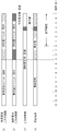
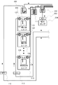
- FIG. 2 is a block diagram illustrating a configuration of an aroma supply device according to the first embodiment. It is a timing chart which shows the switching timing of a two-way valve and a three-way valve. It is a block diagram which shows the structure of the aroma supply apparatus which concerns on Embodiment 2. It is a block diagram showing composition of a fragrance supply device concerning other forms. It is a block diagram showing composition of a fragrance supply device concerning other forms. It is a block diagram which shows the structure of the conventional aroma supply apparatus.
- the scent supply device 1 is a device for supplying a gas having a scent to a subject, and is used for an olfactory test for determining whether or not the subject detects the scent.
- FIG. 1 is a block diagram showing the configuration of the scent supply device 1 according to the present embodiment.
- the scent supply device 1 has two systems, a background scent system and a target scent system.
- the fragrance supply device 1 includes a flow path branching device 201 for passing gas flowing from the background scent system and the target scent system, a three-way valve 202 for passing one of the background scent system and the target scent system, A mass flow controller (MFC) 203 that adjusts the flow rate of the air, a suction pump 204 that suctions gas, and an exhaust device 205 that supplies the gas that has passed through the flow path brancher 201 to the nasal cavity of the subject.
- MFC mass flow controller
- the three-way valve 202 is any three-way valve that is electrically driven, and is, for example, a three-way solenoid valve or a three-way electric valve.
- the three-way valve 202 switches the valve based on a control signal from a control unit that controls the operation of the fragrance supply device 1.
- the background incense system includes a compression pump 101, a deodorizing device 103, a mass flow controller 112, a background incense unit 106, an odorless air unit 107, and a humidification unit 108.
- the target incense system includes a compression pump 101, a nitrogen generator 102, a deodorizer 104, a mass flow controller 113, a target incense unit 109, an odorless nitrogen unit 110, and a heater 111.
- the background incense unit 106 has a set of first two-way valves 121 in the inflow path and the outflow path, and accommodates a sample that is a source of background incense.
- the odorless air unit 107 has a pair of second two-way valves 122 in the inflow path and the outflow path, and allows odorless air to pass through.
- the background incense unit 106 and the odorless air unit 107 are connected in parallel to each other in the background incense flow path, and the inflow ports of the first two-way valve 121 and the second two-way valve 122 on the inflow path side are respectively mass flow controllers. 112.
- the outlets of the first two-way valve 121 and the second two-way valve 122 on the outflow path side are connected to the humidification unit 108, respectively.
- the first two-way valve 121 and the second two-way valve 122 are any two-way valves that are electrically driven, and are, for example, two-way solenoid valves or two-way electric valves.
- the first two-way valve 121 and the second two-way valve 122 open and close based on a control signal from a control unit that controls the operation of the aroma supply device 1.
- the odorless air discharged from the compression pump 101 and deodorized by the deodorizing device 103 flows into the mass flow controller 112 and the flow rate is adjusted.
- the mass flow controller 112 flows out.
- the odorless air passes only through the background incense unit 106.
- the odorless air flows out toward the humidifying unit 108 with the background scent attached by the background scent unit 106.
- the method of applying the background scent of the background scent unit 106 may be any method. However, since a method that lasts for a long time is preferable, for example, bubbling may be performed in a liquid sample that is a source of the background scent.
- the odorless Air passes only through the odorless air unit 107.
- the odorless air flows out toward the humidification unit 108 while keeping the odorless air in the odorless air unit 107.
- Humidification unit 108 contains deionized water. The gas flowing into the humidification unit 108 is humidified by passing through deionized water.
- the target incense unit 109 has a set of third two-way valves 123 in the inflow path and the outflow path, and accommodates a sample that is a source of the target incense.
- the odorless nitrogen unit 110 has a pair of fourth two-way valves 124 in the inflow path and the outflow path, and allows odorless nitrogen to pass.
- the target incense unit 109 and the odorless nitrogen unit 110 are connected in parallel to each other in a target incense system flow path, and the inflow ports of the third two-way valve 123 and the fourth two-way valve 124 on the inflow path side are mass flow controllers, respectively. 113.
- the outlets of the third two-way valve 123 and the fourth two-way valve 124 on the outflow path side are connected to the heater 111, respectively.
- the third two-way valve 123 and the fourth two-way valve 124 are any two-way valves that are electrically driven, and are, for example, two-way solenoid valves or two-way electric valves.
- the third two-way valve 123 and the fourth two-way valve 124 open and close based on a control signal from a control unit that controls the operation of the aroma supply device 1.
- the nitrogen generator 102 generates nitrogen gas from the air flowing out of the compression pump 101, and the odorless nitrogen deodorized by the deodorizer 104 flows into the mass flow controller 113 to adjust the flow rate.
- the set of the third two-way valve 123 of the target incense unit 109 is opened and the set of the fourth two-way valve 124 of the odorless nitrogen unit 110 is closed, it flows out of the mass flow controller 113.
- Odorless nitrogen passes only through the target incense unit 109.
- the odorless nitrogen flows out toward the heater 111 in a state where the target scent is applied by the target scent unit 109.
- the method of applying the target incense of the target incense unit 109 may be any method.
- the target incense unit 109 may be passed through absorbent cotton to which a sample serving as a source of the target incense is attached.
- the odorless liquid flowing out of the mass flow controller 113 is opened. Nitrogen passes only through the odorless nitrogen unit 110. The odorless nitrogen flows toward the heater 111 while keeping the odorless nitrogen in the odorless nitrogen unit 110. The gas flowing into the heater 111 is heated by the heater 111, and its temperature is adjusted so as to approximate the temperature of the background incense-based gas.
- the flow path branching device 201 into which the background incense-based gas and the target incense-based gas flow in is provided with two 2 ⁇ 1 couplers (connection ports are A, B, and C).
- the background incense-based gas flows into the connection port A of the coupler, and the target incense-based gas flows into the connection port A of the second coupler.
- the connection port B of the first coupler is connected to one connection port of the three-way valve 202, and the connection port B of the second coupler 202 is connected to the other connection port of the three-way valve 202.
- the connection port C of the first coupler and the connection port C of the second coupler are both connected to the exhaust device 205 that supplies the nasal cavity of the subject.
- the three-way valve 202 is a three-way valve that connects two of the three connection ports, and is switched based on a control signal from the control unit. Of the three connection ports of the three-way valve 202, a connection port that is not connected to the flow path branching device 201 is connected to the mass flow controller 203. The gas passing through the three-way valve 202 has its flow rate adjusted by the mass flow controller 203 and is sucked by the suction pump 204.
- the background scent-based gas flowing into the flow path branching unit 201 is suction pumped through the mass flow controller 203. Since the air is sucked by the exhaust 204, the air is not exhausted from the exhaust device 205. At this time, the target incense-based gas that has flowed into the flow path branch 201 passes through the flow path branch 201, is discharged from the exhaust device 205, and is supplied to the nasal cavity of the subject.
- the target scent-based gas flowing into the flow path branching unit 201 is sucked into the suction pump 204 via the mass flow controller 203. Therefore, the air is not exhausted from the exhaust device 205. At this time, the background scent-based gas that has flowed into the flow path branch 201 passes through the flow path branch 201, is discharged from the exhaust device 205, and is supplied to the subject's nasal cavity.
- FIG. 2 is a timing chart showing the timing of switching between the two-way valve and the three-way valve by the control unit.
- the odorless air is exhausted from the exhaust device 205.
- the first two-way valve 121 of the background incense unit 106 is closed, and the second two-way valve 122 of the odorless air unit 107 is opened, so that odorlessness is obtained.
- Air flows into the humidification unit 108.
- the odorless air humidified by the humidification unit 108 flows into the flow path branching device 201.
- the third two-way valve 123 of the target incense unit 109 is closed, and the fourth two-way valve 124 of the odorless nitrogen unit 110 is opened.
- the odorless nitrogen whose temperature has been adjusted by the heater 111 flows into the flow path branching device 201.
- the three-way valve 202 is set in a state of passing the target incense-based gas as shown in FIG.
- the suction pump 204 sucks the gas of the target incense system, that is, the odorless nitrogen through the mass flow controller 203.
- the mass flow controller 203 controls the odorless air and odorless nitrogen flowing into the flow path branch 201.
- the odorless air and odorless nitrogen flowing into the flow path branch 201 only the odorless air passes through the flow path branch 201 and the exhaust device 205 and is supplied to the subject.
- the scent supply device 1 starts supplying the background scent.
- each unit since each unit is installed at a position several meters away from the exhaust device 205, it takes time to switch the gas supplied to the subject. Therefore, it is necessary to determine the control timing of each two-way valve and three-way valve in consideration of the time required for gas switching. For example, several seconds before the start of the test, the outflow of the background scent and the target scent is started.
- the first two-way valve 121 of the background incense unit 106 is opened, and the second two-way valve 122 of the odorless air unit 107 is closed. Then, the air with the background scent flows into the humidifying unit 108. The air with the background scent humidified by the humidification unit 108 flows into the flow path branching device 201. 2B, the third two-way valve 123 of the target incense unit 109 is opened, and the fourth two-way valve 124 of the odorless nitrogen unit 110 is closed, so that the target incense is released. Flows into the heater 111. The nitrogen with the target scent, the temperature of which has been adjusted by the heater 111, flows into the flow path branching unit 201.
- the three-way valve 202 is set so as not to switch from the normal state and to pass the target incense-based gas.
- the suction pump 204 sucks the target scent-based gas, that is, nitrogen with the target scent, through the mass flow controller 203.
- the subject inserts the exhaust device 205 into the nasal cavity and starts the olfactory test.
- the scent supply device 1 temporarily supplies the target scent. Specifically, as shown in FIG. 2A, the first two-way valve 121 and the second two-way valve 122 of the background incense are not switched, and the background incense is added from the background incense. The flowed air flows into the flow path branching device 201. Further, as shown in FIG. 2B, the third two-way valve 123 and the fourth two-way valve 124 of the target incense system are not switched, and nitrogen with the target incense is discharged from the target incense system. It flows into the flow path branch 201.
- the three-way valve 202 is temporarily switched to a state in which the background incense gas passes as shown in FIG. Thereby, the suction pump 204 sucks the background-scented gas, that is, the air with the background scent, via the mass flow controller 203. Then, of the air with the background scent and the nitrogen with the target scent that flowed into the flow path branch 201, only the nitrogen with the target scent passed through the flow branch 201 and the exhaust device 205, and Supplied.
- the scent supply device 1 can supply the background scent to the subject and insert the target scent in a pulsed manner.
- the subject examines whether a target scent different from the background scent can be detected.
- the background scent unit 106 and the odorless air unit 107 are inserted in parallel into the background scent-based flow path, and the target scent-based flow path is set in the target scent-based flow path.
- Unit 109 and odorless nitrogen unit 110 are inserted in parallel with each other.
- the scent supply device 1 switches the odorless air, the background scented air, and the target scented nitrogen. To supply.
- the scent supply device 2 is a device that determines whether or not a subject detects a scent by flowing gas with a scent toward the subject in the same manner as in the first embodiment.
- FIG. 3 is a block diagram illustrating a part of the configuration of the scent supply device 2 according to the present embodiment. As shown in FIG. 3, the scent supply device 2 includes a background scent system and a target scent system.
- One of the background scent-based gas and the target scent-based gas is suctioned by the suction pump 204 via the three-way valve 202 and the mass flow controller 203, and the other passes through the flow path branching device 201 and is discharged from the exhaust device 205 to the subject.
- the point supplied to the nasal cavity is the same as in the first embodiment.
- the second embodiment differs from the first embodiment in that a plurality of background incense units 106 and a plurality of target incense units 109 are provided.
- a plurality of background incense units 106 are connected in parallel with each other.
- Each background incense unit 106 has a pair of first two-way valves 121 in the inflow path and the outflow path, and accommodates different samples serving as sources of background incense.
- the background incense system includes an odorless air unit 107 as in the first embodiment, and is connected in parallel with the background incense unit 106.
- One of a plurality of first two-way valves 121 of a plurality of background incense units 106 and a second set of two-way valves 122 of a set of an odorless air unit 107 are opened, and all others are closed. With this, it is possible to switch which unit allows the odorless air to pass through. That is, by switching between the first two-way valve 121 and the second two-way valve 122, air with any one of the background incense can flow out, or odorless air can flow out.
- a plurality of target incense units 109 are connected to each other in parallel.
- Each target incense unit 109 has a pair of third two-way valves 123 in the inflow path and the outflow path, and accommodates different samples serving as sources of target incense.
- the target incense system includes an odorless nitrogen unit 110 as in the first embodiment, and is connected in parallel with the target incense unit 109.
- the odorless air is exhausted from the exhaust device 205.
- the first two-way valves 121 of all the background incense units 106 are closed, and the second two-way valves 122 of the odorless air unit 107 are opened.
- odorless air flows into the humidification unit 108.
- the odorless air humidified by the humidification unit 108 flows into the flow path branching device 201.
- the third two-way valves 123 of all the target incense units 109 are closed, and the fourth two-way valves 124 of the odorless nitrogen unit 110 are opened. Odorless nitrogen flows into the heater 111. The odorless nitrogen whose temperature has been adjusted by the heater 111 flows into the flow path branching device 201.
- the three-way valve 202 is set in a state of passing the target incense-based gas as shown in FIG.
- the suction pump 204 sucks the gas of the target incense system, that is, the odorless nitrogen through the mass flow controller 203.
- the mass flow controller 203 controls the odorless air and odorless nitrogen flowing into the flow path branch 201.
- the odorless air and odorless nitrogen flowing into the flow path branch 201 only the odorless air passes through the flow path branch 201 and the exhaust device 205 and is supplied to the subject.
- the scent supply device 2 starts supplying the background scent. Specifically, as shown in FIG. 2A, one of the plurality of background incense units 106 is opened by the first two-way valve 121, and the first two-way valve 121 of the other background incense unit 106 is opened. When the one-way valve 121 and the second two-way valve 122 of the odorless air unit 107 are closed, the air with the selected background scent flows into the humidification unit 108. The air with the background scent humidified by the humidification unit 108 flows into the flow path branching device 201.
- one of the plurality of target incense units 109 is opened, and the third two-way valve 123 of the other target incense unit 109 is opened.
- the fourth two-way valve 124 of the odorless nitrogen unit 110 is closed, the nitrogen with the selected target scent flows into the heater 111.
- the nitrogen with the target scent flows into the flow path branching unit 201.
- the three-way valve 202 is set so as not to switch from the normal state and to pass the target incense-based gas.
- the suction pump 204 sucks the target scent-based gas, that is, nitrogen with the target scent, through the mass flow controller 203.
- the subject inserts the exhaust device 205 into the nasal cavity and starts the olfactory test.
- the scent supply device 2 temporarily supplies the selected target scent. Specifically, as shown in FIG. 2A, the first two-way valve 121 and the second two-way valve 122 of all the background incense systems are not switched, and the selection is made from the background incense system. The air with the background scent flows into the flow path branching device 201. Further, as shown in FIG. 2B, the switching of the third two-way valve 123 and the fourth two-way valve 124 of the target incense system is not performed, and the selected target incense is added from the target incense system. The dropped nitrogen flows into the flow path branching device 201.
- the three-way valve 202 is temporarily switched to a state in which the background incense gas passes as shown in FIG.
- the suction pump 204 sucks the background-scented gas, that is, the air with the selected background scent, via the mass flow controller 203.
- the mass flow controller 203 controls the suction pump 204 to a state in which the background incense gas.
- the suction pump 204 sucks the background-scented gas, that is, the air with the selected background scent, via the mass flow controller 203.
- the nitrogen with the selected target scent passed through the flow path splitter 201 and the exhaust device 205. , Supplied to the subject.
- the scent supply device 2 can supply the subject with the background scent selected from the plurality of background scents and insert the target scent selected from the plurality of target scents in a pulsed manner.
- the supply of the scent to the subject can be performed by sequentially changing the type of the background scent and the type of the target scent to different combinations.
- the scent supply device 2 includes the background scent unit 106 and the odorless air unit 107 inserted in parallel into the background scent-based flow path,
- the target incense unit 109 and the odorless nitrogen unit 110 are inserted in parallel with each other.
- the plurality of target incense units can be opened. Nitrogen or odorless nitrogen with the target odor selected from the above is discharged. Further, by switching the three-way valve 202 that connects the target scent-based flow path and the background scent-based flow path, the scent supply device 2 applies the odorless air, the air with the selected background scent, and the selected target scent. The supplied nitrogen was switched and supplied. Thus, with a simple configuration, it is possible to temporarily insert the target incense selected from the plurality of types into the flow of the background incense selected from the plurality of types, and perform an inspection for discriminating various target incense.
- the target incense-based flow path and the background incense-based flow path are connected to the three-way valve, and by switching the three-way valve, one of the target incense-based gas and the background incense-based gas is switched.
- a background incense unit that is inserted into a background incense-based flow path has a first two-way valve in each of an inflow path and an outflow path, and stores a sample that is a source of background incense.
- a odorless air unit that is connected in parallel with the background scent unit in the background scent-based flow path, has a second two-way valve in each of the inflow path and the outflow path, and allows odorless air to pass therethrough. One of the two-way valve and the second two-way valve is opened, and the other is closed to switch whether or not to supply the background incense. This makes it possible to temporarily insert the target incense into the flow of the background incense with a simple configuration.
- the target scent system of the scent supply device 1 is such that the target scent unit 109 and the odorless nitrogen unit 110 are connected in parallel, and the switching between the third two-way valve 123 and the fourth two-way valve 124 is performed.
- the configuration of the target scent system may be such that the odorless nitrogen flows directly into the target scent unit 109.
- the background incense system may have a configuration in which a plurality of background incense units 106 are connected in parallel.
- the background scent system of the scent supply device 2 includes a plurality of background scent units 106 and an odorless air unit 107 connected in parallel to each other, and includes a first two-way valve 121 and a second two-way valve 122.
- the scent supply device 2 supplies odorless air without a background scent system, and a nitrogen containing a target scent selected from a plurality of target scents in a flow of the odorless air. May be temporarily inserted.
Landscapes
- Physics & Mathematics (AREA)
- Health & Medical Sciences (AREA)
- Life Sciences & Earth Sciences (AREA)
- Chemical & Material Sciences (AREA)
- Analytical Chemistry (AREA)
- Biochemistry (AREA)
- General Health & Medical Sciences (AREA)
- General Physics & Mathematics (AREA)
- Immunology (AREA)
- Pathology (AREA)
- Sampling And Sample Adjustment (AREA)
- Disinfection, Sterilisation Or Deodorisation Of Air (AREA)
Abstract
香気供給装置(1)は、背景香系の流路に、背景香ユニット(106)と無臭空気ユニット(107)を互いに並列に挿入し、標的香系の流路に標的香ユニット(109)と無臭窒素ユニット(110)を互いに並列に挿入している。背景香ユニット(106)の第1の二方弁(121)と無臭空気ユニット(107)の第2の二方弁(122)とのいずれか一方のみを開弁することにより、背景香を付した空気又は無臭空気が流出する。また、標的香ユニット(109)の第3の二方弁(123)と無臭窒素ユニット(110)の第4の二方弁(124)とのいずれか一方のみを開弁することにより、標的香を付した窒素又は無臭窒素が流出する。さらに香気供給装置(1)は、三方弁(202)を切り替えることにより、無臭空気、背景香を付した空気、標的香を付した窒素を切り替えて供給する。
Description
本発明は、標的香を付した気体を供給する香気供給装置に関する。
人の嗅覚を検査する方法は、種類又は強さの異なる香りを発生させ、その香りを人が検知できるか否かにより判断する方法が知られている。本願の発明者の一人は、第1の接続弁で、複数のニオイラインと提示用マスクとの接続を切り替え、第2の接続弁で、無臭空気ラインと提示用マスクとの接続を切り替える気体提示装置を提案した(特許文献1)。
また、香気を供給する装置として、Kobal式オルファクトメータが市販されている。Kobal式オルファクトメータは、例えば、図6に示すように、無臭空気の系と香気の系とを備えている。無臭空気の系には、圧縮ポンプから送られてくる無臭空気が常時流れている。また、香気の系には、標的香を付した脱脂綿を内部に備えた標的香ユニット109に窒素を通過させることにより、標的香を付した窒素が常時流れている。この2つの系を三方弁202で切り替えることにより、無臭空気と標的香を付した窒素のいずれか一方の気体を、被験者が鼻腔に差し込む排気器具205から排出させる。検査時には、排気器具205からは、通常、無臭空気が排出されており、この無臭空気の流れの中に標的香がパルス的に挿入され、被験者がそれを検知できるか否かを判定する。
人の嗅覚の検査において、標的香とは異なる背景香の流れの中に標的香を一時的に挿入し、標的香の挿入を検知できるか否かの検査もある。また、1セッションの検査の中で、複数種類の標的香の挿入を検知できるか否かの検査もある。
従来のオルファクトメータは、一方の系から無臭空気を供給し他方の系から標的香を付した窒素を供給するため、背景香を供給することができず、背景香の流れの中の標的香を検知する検査に対応できなかった。また、複数種類の標的香を提示する検査にも対応できず、これらの検査に対応するためには新たな機構を組み込む必要があったが、多額な費用を要するという課題があった。
本発明は、上記実情に鑑みてなされたものであり、簡易な構成で、背景香の流れの中に標的香を一時的に挿入することのできる香気供給装置を提供することを目的とする。
上記目的を達成するため、本発明の第1の観点に係る香気供給装置は、
標的香を付した気体が流れる標的香系の流路と、前記標的香系の流路とは異なる背景香系の流路とが三方弁に接続され、前記三方弁の切り替えにより、前記標的香系の気体と前記背景香系の気体とのいずれか一方を供給する香気供給装置であって、
前記背景香系の流路に挿入され、一組の第1の二方弁を流入路及び流出路に有し、背景香の発生源となる試料を収容した背景香ユニットと、
前記背景香系の流路において、前記背景香ユニットと並列に接続され、一組の第2の二方弁を流入路及び流出路に有し、無臭空気を通過させる無臭空気ユニットと、を備え、
前記第1の二方弁の組と前記第2の二方弁の組のいずれか1組を開弁し、他方を閉弁することにより、背景香を供給するか否かを切り替えることを特徴とする。
標的香を付した気体が流れる標的香系の流路と、前記標的香系の流路とは異なる背景香系の流路とが三方弁に接続され、前記三方弁の切り替えにより、前記標的香系の気体と前記背景香系の気体とのいずれか一方を供給する香気供給装置であって、
前記背景香系の流路に挿入され、一組の第1の二方弁を流入路及び流出路に有し、背景香の発生源となる試料を収容した背景香ユニットと、
前記背景香系の流路において、前記背景香ユニットと並列に接続され、一組の第2の二方弁を流入路及び流出路に有し、無臭空気を通過させる無臭空気ユニットと、を備え、
前記第1の二方弁の組と前記第2の二方弁の組のいずれか1組を開弁し、他方を閉弁することにより、背景香を供給するか否かを切り替えることを特徴とする。
前記背景香ユニットの後段に、脱イオン水を収容した加湿ユニットを更に備えてもよい。
前記標的香系の流路に挿入され、一組の第3の二方弁を流入路及び流出路に有し、標的香の発生源となる試料を収容した標的香ユニットと、
前記標的香系の流路において、前記標的香ユニットと並列に接続され、一組の第4の二方弁を流入路及び流出路に有し、無臭窒素を通過させる無臭窒素ユニットと、を更に備え、
前記第3の二方弁の組と前記第4の二方弁の組のいずれか1組を開弁し、他方を閉弁することにより、標的香を供給するか否かを切り替えてもよい。
前記標的香系の流路において、前記標的香ユニットと並列に接続され、一組の第4の二方弁を流入路及び流出路に有し、無臭窒素を通過させる無臭窒素ユニットと、を更に備え、
前記第3の二方弁の組と前記第4の二方弁の組のいずれか1組を開弁し、他方を閉弁することにより、標的香を供給するか否かを切り替えてもよい。
前記標的香ユニットの後段に、標的香系の気体の温度を背景香系の気体の温度に近似させるヒーターを更に備えてもよい。
前記標的香ユニットを複数備え、複数の前記標的香ユニットを互いに並列に接続し、複数組の前記第3の二方弁と一組の前記第4の二方弁のいずれか1組を開弁し、他の組の二方弁を閉弁することにより、複数の標的香のいずれか1つを供給するか、前記標的香を供給しないかを切り替えてもよい。
前記背景香ユニットを複数備え、複数の前記背景香ユニットを互いに並列に接続し、複数組の前記第1の二方弁と一組の前記第2の二方弁のいずれか1組を開弁し、他の組の二方弁を閉弁することにより、複数の背景香のいずれか1つを供給するか、前記背景香を供給しないかを切り替えてもよい。
本発明によれば、簡易な構成で、背景香の流れの中に標的香を一時的に挿入することが可能となる。
(実施形態1)
以下、本発明の実施形態1について図面を参照して詳細に説明する。
以下、本発明の実施形態1について図面を参照して詳細に説明する。
本実施形態に係る香気供給装置1は、香りを有する気体を被検者に向けて供給する装置であり、被検者がその香りを検知するか否かを判定する嗅覚の検査に用いられる。
図1は、本実施形態に係る香気供給装置1の構成を示すブロック図である。香気供給装置1は、図1に示すように、背景香系と標的香系との二系統を有している。香気供給装置1は、背景香系と標的香系から流れてくる気体を通過させる流路分岐器201と、背景香系と標的香系のいずれか一方の気体を通過させる三方弁202と、気体の流量を調整するマスフローコントローラ(Mass Flow Controller:MFC)203と、気体を吸引する吸引ポンプ204と、流路分岐器201を通過した気体を被験者の鼻腔に供給する排気器具205と、を備える。三方弁202は、電気で駆動する任意の三方弁であり、例えば、三方電磁弁又は三方電動弁である。三方弁202は、香気供給装置1の動作を制御する制御部からの制御信号に基づいて、弁を切り替える。
背景香系は、圧縮ポンプ101と、脱臭装置103と、マスフローコントローラ112と、背景香ユニット106と、無臭空気ユニット107と、加湿ユニット108と、を備える。標的香の系は、圧縮ポンプ101と、窒素発生装置102と、脱臭装置104と、マスフローコントローラ113と、標的香ユニット109と、無臭窒素ユニット110と、ヒーター111と、を備える。
背景香系において、背景香ユニット106は、一組の第1の二方弁121を流入路及び流出路に有し、背景香の発生源となる試料を収容している。無臭空気ユニット107は、一組の第2の二方弁122を流入路及び流出路に有し、無臭空気を通過させる。背景香ユニット106と無臭空気ユニット107は、背景香系の流路において、互いに並列に接続され、流入路側の第1の二方弁121及び第2の二方弁122の流入口がそれぞれマスフローコントローラ112に接続されている。また、流出路側の第1の二方弁121及び第2の二方弁122の流出口がそれぞれ加湿ユニット108に接続されている。第1の二方弁121、第2の二方弁122は、電気で駆動する任意の二方弁であり、例えば、二方電磁弁又は二方電動弁である。第1の二方弁121、第2の二方弁122は、香気供給装置1の動作を制御する制御部からの制御信号に基づいて、弁を開閉させる。
背景香系において、圧縮ポンプ101より流出され、脱臭装置103で脱臭された無臭空気がマスフローコントローラ112に流入し流量が調整される。ここで、背景香ユニット106の第1の二方弁121の組を開弁し、無臭空気ユニット107の第2の二方弁122の組を閉弁した場合には、マスフローコントローラ112から流出した無臭空気は、背景香ユニット106のみを通過する。無臭空気は、背景香ユニット106で背景香が付された状態で、加湿ユニット108に向かって流出する。背景香ユニット106の背景香を付す方法は任意の方法でよいが、長時間持続する方法が好ましいため、例えば、背景香の発生源となる液体の試料の中でバブリングしてもよい。
一方、背景香ユニット106の第1の二方弁121の組を閉弁し、無臭空気ユニット107の第2の二方弁122の組を開弁した場合には、マスフローコントローラ112から流出した無臭空気は、無臭空気ユニット107のみを通過する。無臭空気は、無臭空気ユニット107で無臭を保った状態で、加湿ユニット108に向かって流出する。加湿ユニット108は、脱イオン水を収容している。加湿ユニット108に流入した気体は、脱イオン水の中を通過することにより加湿される。
標的香系において、標的香ユニット109は、一組の第3の二方弁123を流入路及び流出路に有し、標的香の発生源となる試料を収容している。無臭窒素ユニット110は、一組の第4の二方弁124を流入路及び流出路に有し、無臭窒素を通過させる。標的香ユニット109と無臭窒素ユニット110は、標的香系の流路において、互いに並列に接続され、流入路側の第3の二方弁123及び第4の二方弁124の流入口がそれぞれマスフローコントローラ113に接続されている。また、流出路側の第3の二方弁123及び第4の二方弁124の流出口がそれぞれヒーター111に接続されている。第3の二方弁123、第4の二方弁124は、電気で駆動する任意の二方弁であり、例えば、二方電磁弁又は二方電動弁である。第3の二方弁123、第4の二方弁124は、香気供給装置1の動作を制御する制御部からの制御信号に基づいて、弁を開閉させる。
標的香系において、圧縮ポンプ101より流出する空気から窒素発生装置102が窒素ガスを生成し、脱臭装置104で脱臭された無臭窒素がマスフローコントローラ113に流入し流量が調整される。ここで、標的香ユニット109の第3の二方弁123の組を開弁し、無臭窒素ユニット110の第4の二方弁124の組を閉弁した場合には、マスフローコントローラ113から流出した無臭窒素は、標的香ユニット109のみを通過する。無臭窒素は、標的香ユニット109で標的香が付された状態で、ヒーター111に向かって流出する。標的香ユニット109の標的香を付す方法は任意の方法でよいが、例えば、標的香の発生源となる試料を付した脱脂綿を通過させてもよい。
一方、標的香ユニット109の第3の二方弁123の組を閉弁し、無臭窒素ユニット110の第4の二方弁124の組を開弁した場合には、マスフローコントローラ113から流出した無臭窒素は、無臭窒素ユニット110のみを通過する。無臭窒素は、無臭窒素ユニット110で無臭を保った状態で、ヒーター111に向かって流出する。ヒーター111に流入した気体は、ヒーター111で加温され、背景香系の気体の温度に近似させるように温度調整される。
背景香系の気体と標的香系の気体が流入する流路分岐器201は、2×1のカプラ(接続口をA,B,Cとする)を二つ備えたものであり、第1のカプラの接続口Aに背景香系の気体が流入し、第2のカプラの接続口Aに標的香系の気体が流入する。第1のカプラの接続口Bは三方弁202の1つの接続口に接続され、第2のカプラの接続口Bは三方弁202の他の接続口に接続される。第1のカプラの接続口C及び第2のカプラの接続口Cは、共に被験者の鼻腔に供給する排気器具205に接続されている。
三方弁202は、3つの接続口のうち2つの接続口間を接続する三方弁であり、制御部からの制御信号に基づいて切り替えられる。三方弁202の3つの接続口のうち、流路分岐器201に接続されていない接続口はマスフローコントローラ203に接続されている。三方弁202を通過する気体は、マスフローコントローラ203で流量を調整され、吸引ポンプ204で吸引される。
三方弁202が、制御部の制御により背景香系の気体を通過する状態に設定している時、流路分岐器201に流入された背景香系の気体は、マスフローコントローラ203を介して吸引ポンプ204に吸引されるため、排気器具205からは排気されない。このとき、流路分岐器201に流入された標的香系の気体は、流路分岐器201を通過して排気器具205から排出され、被検者の鼻腔に供給される。
一方、三方弁202が、標的香系の気体を通過する状態に設定している時、流路分岐器201に流入された標的香系の気体は、マスフローコントローラ203を介して吸引ポンプ204に吸引されるため、排気器具205からは排気されない。このとき、流路分岐器201に流入された背景香系の気体は、流路分岐器201を通過して排気器具205から排出され、被検者の鼻腔に供給される。
以上のように構成された香気供給装置1の動作について、図2のタイミングチャートに沿って詳細に説明する。図2は制御部による各二方弁と三方弁の切り替えのタイミングを示すタイミングチャートである。
香気供給装置1の駆動を開始後、通常は、無臭空気が排気器具205から排気されている。このとき、図2(a)に示すように、背景香ユニット106の第1の二方弁121が閉弁し、無臭空気ユニット107の第2の二方弁122が開弁することにより、無臭空気が加湿ユニット108に流入する。加湿ユニット108で加湿された無臭空気は、流路分岐器201に流入する。また、図2(b)に示すように、標的香ユニット109の第3の二方弁123が閉弁し、無臭窒素ユニット110の第4の二方弁124が開弁することにより、無臭窒素がヒーター111に流入する。ヒーター111で温度調整された無臭窒素は、流路分岐器201に流入する。
このとき、三方弁202は、図2(c)に示すように標的香系の気体を通過する状態に設定されている。これにより、吸引ポンプ204は、マスフローコントローラ203を介して標的香系の気体、すなわち無臭窒素を吸引する。そして、流路分岐器201に流入した無臭空気と無臭窒素のうち、無臭空気のみが流路分岐器201、排気器具205を通過して、被験者に供給される。
次に、嗅覚検査の開始に先立ち、香気供給装置1は背景香の供給を開始する。ここで、各ユニットは、排気器具205から数m離れた位置に設置されるため、被験者に供給する気体の切り替えに時間を要する。よって、各二方弁と三方弁の制御のタイミングは気体の切り替えに要する時間を考慮して決定する必要がある。例えば、検査開始の数秒前に背景香、標的香の流出を開始させる。
具体的には、図2(a)に示すように、背景香ユニット106の第1の二方弁121が開弁し、無臭空気ユニット107の第2の二方弁122が閉弁することにより、背景香を付した空気が加湿ユニット108に流入する。加湿ユニット108で加湿された背景香を付した空気は、流路分岐器201に流入する。また、図2(b)に示すように、標的香ユニット109の第3の二方弁123が開弁し、無臭窒素ユニット110の第4の二方弁124が閉弁することにより、標的香を付した窒素がヒーター111に流入する。ヒーター111で温度調整された標的香を付した窒素は、流路分岐器201に流入する。
このとき、三方弁202は、図2(c)に示すように、通常状態から切り替えを行わず、標的香系の気体を通過する状態に設定されている。これにより、吸引ポンプ204は、マスフローコントローラ203を介して標的香系の気体、すなわち標的香を付した窒素を吸引する。そして、流路分岐器201に流入した背景香を付した空気と標的香を付した窒素のうち、背景香を付した空気のみが流路分岐器201と排気器具205を通過して、被験者に供給される。背景香を付した空気が供給されている状態で、被験者が排気器具205を鼻腔に差し込み、嗅覚の検査を開始する。
その後、予め定めたタイミングで、香気供給装置1は標的香を一時的に供給する。具体的には、図2(a)に示すように、背景香系の第1の二方弁121及び第2の二方弁122の切り替えを行わず、背景香系からは、背景香を付した空気が流路分岐器201に流入する。また、図2(b)に示すように、標的香系の第3の二方弁123及び第4の二方弁124の切り替えを行わず、標的香系からは、標的香を付した窒素が流路分岐器201に流入する。
そして、予め定めたタイミングで三方弁202が、図2(c)に示すように、背景香系の気体を通過する状態に一時的に切り替えられる。これにより、吸引ポンプ204は、マスフローコントローラ203を介して背景香系の気体、すなわち背景香を付した空気を吸引する。そして、流路分岐器201に流入した背景香を付した空気と標的香を付した窒素のうち、標的香を付した窒素のみが流路分岐器201と排気器具205を通過して、被験者に供給される。
このようにして、香気供給装置1は、背景香を被験者に供給し、標的香をパルス状に挿入することができる。被験者は、背景香と異なる標的香を検知できるか否かの検査をする。
以上説明したように、本実施形態において、香気供給装置1は、背景香系の流路に、背景香ユニット106と無臭空気ユニット107が互いに並列に挿入され、標的香系の流路に標的香ユニット109と無臭窒素ユニット110が互いに並列に挿入されている。背景香ユニット106に備えた第1の二方弁121と無臭空気ユニット107に備えた第2の二方弁122とのいずれか一方のみを開弁することにより、背景香を付した空気又は無臭空気が流出する。また、標的香ユニット109に備えた第3の二方弁123と無臭窒素ユニット110に備えた第4の二方弁124とのいずれか一方のみを開弁することにより、標的香を付した窒素又は無臭窒素が流出する。さらに標的香系の流路と背景香系の流路とを接続した三方弁202を切り替えることにより、香気供給装置1は、無臭空気、背景香を付した空気、標的香を付した窒素を切り替えて供給することとした。これにより、簡易な構成で、背景香の流れの中に標的香を一時的に挿入して、標的香を判別する検査が可能となる。
(実施形態2)
以下、本発明の実施形態2について図面を参照して詳細に説明する。
以下、本発明の実施形態2について図面を参照して詳細に説明する。
本実施形態に係る香気供給装置2は、実施形態1と同様に香りを付した気体を被検者に向けて流すことにより、被検者が香りを検知するか否かを判定する装置である。図3は、本実施形態に係る香気供給装置2の構成の一部を示すブロック図である。香気供給装置2は、図3に示すように、背景香系と標的香系とを備えている。
背景香系の気体と標的香系の気体のいずれか一方が三方弁202、マスフローコントローラ203を介して吸引ポンプ204で吸引され、他方が流路分岐器201を通過して排気器具205から被験者の鼻腔に供給される点は、実施形態1と同様である。背景香ユニット106及び標的香ユニット109をそれぞれ複数の備える点が実施形態1と異なる。
本実施形態の背景香系において、複数の背景香ユニット106が、互いに並列に接続されている。各背景香ユニット106は一組の第1の二方弁121を流入路及び流出路に有し、背景香の発生源となる互いに異なる試料を収容している。また、背景香系には、実施形態1と同様に無臭空気ユニット107を備え、背景香ユニット106と並列に接続されている。
複数の背景香ユニット106の複数組の第1の二方弁121と無臭空気ユニット107の一組の第2の二方弁122のいずれか1組を開弁し、他を全て閉弁することにより、無臭空気をどのユニットを通過させるかを切り替えることができる。すなわち、第1の二方弁121及び第2の二方弁122の切り替えにより、いずれか1つの背景香を付した空気を流出させ、又は無臭空気を流出させることができる。
標的香系において、複数の標的香ユニット109が、互いに並列に接続されている。各標的香ユニット109は一組の第3の二方弁123を流入路及び流出路に有し、標的香の発生源となる互いに異なる試料を収容している。また、標的香系には、実施形態1と同様に無臭窒素ユニット110を備え、標的香ユニット109と並列に接続されている。
複数の標的香ユニット109の複数組の第3の二方弁123と無臭窒素ユニット110の一組の第4の二方弁124のいずれか1組を開弁し、他を全て閉弁することにより、無臭窒素をどのユニットを通過させるかを切り替えることができる。すなわち、第3の二方弁123及び第4の二方弁124の切り替えにより、いずれか1つの標的香を付した窒素を流出させ、又は無臭窒素を流出させることができる。
以上のように構成された香気供給装置2の動作について、実施形態1と同様に図2のタイミングチャートに沿って説明する。
香気供給装置2の駆動を開始後、通常は、無臭空気が排気器具205から排気されている。このとき、図2(a)に示すように、全ての背景香ユニット106の第1の二方弁121が閉弁し、無臭空気ユニット107の第2の二方弁122が開弁することにより、無臭空気が加湿ユニット108に流入する。加湿ユニット108で加湿された無臭空気は、流路分岐器201に流入する。
また、図2(b)に示すように、全ての標的香ユニット109の第3の二方弁123が閉弁し、無臭窒素ユニット110の第4の二方弁124が開弁することにより、無臭窒素がヒーター111に流入する。ヒーター111で温度調整された無臭窒素は、流路分岐器201に流入する。
このとき、三方弁202は、図2(c)に示すように標的香系の気体を通過する状態に設定されている。これにより、吸引ポンプ204は、マスフローコントローラ203を介して標的香系の気体、すなわち無臭窒素を吸引する。そして、流路分岐器201に流入した無臭空気と無臭窒素のうち、無臭空気のみが流路分岐器201、排気器具205を通過して、被験者に供給される。
次に、嗅覚検査の開始に先立ち、香気供給装置2は背景香の供給を開始する。具体的には、図2(a)に示すように、複数の背景香ユニット106のうちいずれか1つの第1の二方弁121が開弁し、他の背景香ユニット106の第1の二方弁121及び無臭空気ユニット107の第2の二方弁122が閉弁することにより、選択された背景香を付した空気が加湿ユニット108に流入する。加湿ユニット108で加湿された背景香を付した空気は、流路分岐器201に流入する。
また、図2(b)に示すように、複数の標的香ユニット109のうちいずれか1つの第3の二方弁123が開弁し、他の標的香ユニット109の第3の二方弁123及び無臭窒素ユニット110の第4の二方弁124が閉弁することにより、選択された標的香を付した窒素がヒーター111に流入する。ヒーター111で温度調整された標的香を付した窒素は、流路分岐器201に流入する。
このとき、三方弁202は、図2(c)に示すように、通常状態から切り替えを行わず、標的香系の気体を通過する状態に設定されている。これにより、吸引ポンプ204は、マスフローコントローラ203を介して標的香系の気体、すなわち標的香を付した窒素を吸引する。そして、流路分岐器201に流入した背景香を付した空気と標的香を付した窒素のうち、背景香を付した空気のみが流路分岐器201と排気器具205を通過して、被験者に供給される。選択された背景香を付した空気が供給されている状態で、被験者が排気器具205を鼻腔に差し込み、嗅覚の検査を開始する。
その後、予め定めたタイミングで、香気供給装置2は選択された標的香を一時的に供給する。具体的には、図2(a)に示すように、全ての背景香系の第1の二方弁121及び第2の二方弁122の切り替えを行わず、背景香系からは、選択された背景香を付した空気が流路分岐器201に流入する。また、図2(b)に示すように、標的香系の第3の二方弁123及び第4の二方弁124の切り替えを行わず、標的香系からは、選択された標的香を付した窒素が流路分岐器201に流入する。
そして、予め定めたタイミングで三方弁202が、図2(c)に示すように、背景香系の気体を通過する状態に一時的に切り替えられる。これにより、吸引ポンプ204は、マスフローコントローラ203を介して背景香系の気体、すなわち選択された背景香を付した空気を吸引する。そして、流路分岐器201に流入した背景香を付した空気と標的香を付した窒素のうち、選択された標的香を付した窒素のみが流路分岐器201と排気器具205を通過して、被験者に供給される。
このようにして、香気供給装置2は、複数の背景香から選択された背景香を被験者に供給し、複数の標的香から選択された標的香をパルス状に挿入することができる。被験者への香気の供給は、背景香の種類と標的香の種類を異なる組み合わせに順次変更して、行うことも可能である。
以上説明したように、本実施形態において、香気供給装置2は、背景香系の流路に複数の背景香ユニット106と無臭空気ユニット107が互いに並列に挿入され、標的香系の流路に複数の標的香ユニット109と無臭窒素ユニット110が互いに並列に挿入されている。複数の背景香ユニット106に備えた第1の二方弁121と無臭空気ユニット107に備えた第2の二方弁122とのいずれか1組のみを開弁することにより、複数の背景香から選択した背景香を付した空気又は無臭空気が流出する。また、複数の標的香ユニット109に備えた第3の二方弁123と無臭窒素ユニット110に備えた第4の二方弁124のいずれか1組のみを開弁することにより、複数の標的香から選択した標的香を付した窒素又は無臭窒素が流出する。さらに標的香系の流路と背景香系の流路とを接続した三方弁202を切り替えることにより、香気供給装置2は、無臭空気、選択した背景香を付した空気、選択した標的香を付した窒素を切り替えて供給することとした。これにより、簡易な構成で、複数種類から選択した背景香の流れの中に複数種類から選択した標的香を一時的に挿入して、多様な標的香を判別する検査が可能となる。
このように本発明は、標的香系の流路と背景香系の流路とが三方弁に接続され、三方弁の切り替えにより、標的香系の気体と背景香系の気体とのいずれか一方を供給する香気供給装置において、背景香系の流路に挿入され、流入路と流出路にそれぞれ第1の二方弁を有し、背景香の発生源となる試料を収容した背景香ユニットと、背景香系の流路において、背景香ユニットと並列に接続され、流入路と流出路にそれぞれ第2の二方弁を有し、無臭空気を通過させる無臭空気ユニットと、を備え、第1の二方弁と第2の二方弁のいずれか一方を開弁し、他方を閉弁することにより、背景香を供給するか否かを切り替えることとした。これにより、簡易な構成で、背景香の流れの中に標的香を一時的に挿入することが可能となる。
なお、本発明は、本発明の広義の精神と範囲を逸脱することなく、様々な実施の形態及び変形が可能とされるものである。また、上述した実施の形態は、この発明を説明するためのものであり、本発明の範囲を限定するものではない。すなわち、本発明の範囲は、実施の形態ではなく、特許請求の範囲によって示される。そして、特許請求の範囲内及びそれと同等の発明の意義の範囲内で施される様々な変形が、この発明の範囲内とみなされる。
例えば、実施形態1において、香気供給装置1の標的香系は、標的香ユニット109と無臭窒素ユニット110が並列に接続され、第3の二方弁123と第4の二方弁124との切り替えにより、標的香を付した窒素を供給するか否かを切り替える構成としたが、図4に示すように、標的香系の構成は、無臭窒素を標的香ユニット109に直接流入させる構成にしてもよい。この場合において、実施形態2と同様に、背景香系は複数の背景香ユニット106を並列に接続した構成にしてもよい。
また、実施形態2において、香気供給装置2の背景香系は、複数の背景香ユニット106と無臭空気ユニット107が並列に接続され第1の二方弁121と第2の二方弁122との切り替えにより、背景香のいずれかを供給するか否かを切り替える構成を有し、いずれかの背景香の流れの中に複数の標的香から選択した標的香を付した窒素が一時的に挿入されるとしたが、図5に示すように、香気供給装置2は背景香系を備えずに無臭空気を供給し、無臭空気の流れの中に複数の標的香から選択した標的香を付した窒素を一時的に挿入する構成にしてもよい。
本出願は、2018年7月23日に出願された、日本国特許出願特願2018-138056号に基づく。本明細書中に日本国特許出願特願2018-138056号の明細書、特許請求の範囲、図面全体を参照として取り込むものとする。
1,2…香気供給装置
101…圧縮ポンプ
102…窒素発生装置
103,104…脱臭装置
106…背景香ユニット
107…無臭空気ユニット
108…加湿ユニット
109…標的香ユニット
110…無臭窒素ユニット
111…ヒーター
112,113,203…マスフローコントローラ
121…第1の二方弁
122…第2の二方弁
123…第3の二方弁
124…第4の二方弁
201…流路分岐器
202…三方弁
204…吸引ポンプ
205…排気器具
101…圧縮ポンプ
102…窒素発生装置
103,104…脱臭装置
106…背景香ユニット
107…無臭空気ユニット
108…加湿ユニット
109…標的香ユニット
110…無臭窒素ユニット
111…ヒーター
112,113,203…マスフローコントローラ
121…第1の二方弁
122…第2の二方弁
123…第3の二方弁
124…第4の二方弁
201…流路分岐器
202…三方弁
204…吸引ポンプ
205…排気器具
Claims (6)
- 標的香を付した気体が流れる標的香系の流路と、前記標的香系の流路とは異なる背景香系の流路とが三方弁に接続され、前記三方弁の切り替えにより、前記標的香系の気体と前記背景香系の気体とのいずれか一方を供給する香気供給装置であって、
前記背景香系の流路に挿入され、一組の第1の二方弁を流入路及び流出路に有し、背景香の発生源となる試料を収容した背景香ユニットと、
前記背景香系の流路において、前記背景香ユニットと並列に接続され、一組の第2の二方弁を流入路及び流出路に有し、無臭空気を通過させる無臭空気ユニットと、を備え、
前記第1の二方弁の組と前記第2の二方弁の組のいずれか1組を開弁し、他方を閉弁することにより、背景香を供給するか否かを切り替える、
香気供給装置。 - 前記背景香ユニットの後段に、脱イオン水を収容した加湿ユニットを更に備える、
請求項1に記載の香気供給装置。 - 前記標的香系の流路に挿入され、一組の第3の二方弁を流入路及び流出路に有し、標的香の発生源となる試料を収容した標的香ユニットと、
前記標的香系の流路において、前記標的香ユニットと並列に接続され、一組の第4の二方弁を流入路及び流出路に有し、無臭窒素を通過させる無臭窒素ユニットと、を更に備え、
前記第3の二方弁の組と前記第4の二方弁の組のいずれか1組を開弁し、他方を閉弁することにより、標的香を供給するか否かを切り替える、
請求項1又は2に記載の香気供給装置。 - 前記標的香ユニットの後段に、標的香系の気体の温度を背景香系の気体の温度に近似させるヒーターを更に備える、
請求項3に記載の香気供給装置。 - 前記標的香ユニットを複数備え、複数の前記標的香ユニットを互いに並列に接続し、複数組の前記第3の二方弁と一組の前記第4の二方弁のいずれか1組を開弁し、他の組の二方弁を閉弁することにより、複数の標的香のいずれか1つを供給するか、前記標的香を供給しないかを切り替える、
請求項3又は4に記載の香気供給装置。 - 前記背景香ユニットを複数備え、複数の前記背景香ユニットを互いに並列に接続し、複数組の前記第1の二方弁と一組の前記第2の二方弁のいずれか1組を開弁し、他の組の二方弁を閉弁することにより、複数の背景香のいずれか1つを供給するか、前記背景香を供給しないかを切り替える、
請求項1から5のいずれか1項に記載の香気供給装置。
Applications Claiming Priority (2)
| Application Number | Priority Date | Filing Date | Title |
|---|---|---|---|
| JP2018138056A JP2020016480A (ja) | 2018-07-23 | 2018-07-23 | 香気供給装置 |
| JP2018-138056 | 2018-07-23 |
Publications (1)
| Publication Number | Publication Date |
|---|---|
| WO2020022036A1 true WO2020022036A1 (ja) | 2020-01-30 |
Family
ID=69181406
Family Applications (1)
| Application Number | Title | Priority Date | Filing Date |
|---|---|---|---|
| PCT/JP2019/026842 Ceased WO2020022036A1 (ja) | 2018-07-23 | 2019-07-05 | 香気供給装置 |
Country Status (2)
| Country | Link |
|---|---|
| JP (1) | JP2020016480A (ja) |
| WO (1) | WO2020022036A1 (ja) |
Cited By (1)
| Publication number | Priority date | Publication date | Assignee | Title |
|---|---|---|---|---|
| JP2023148967A (ja) * | 2022-03-30 | 2023-10-13 | 株式会社豊田中央研究所 | 匂い放出装置及び匂い検査装置 |
Families Citing this family (1)
| Publication number | Priority date | Publication date | Assignee | Title |
|---|---|---|---|---|
| JP7486999B2 (ja) * | 2020-04-14 | 2024-05-20 | ジーエルサイエンス株式会社 | におい嗅ぎ装置 |
Citations (6)
| Publication number | Priority date | Publication date | Assignee | Title |
|---|---|---|---|---|
| JPS62231638A (ja) * | 1986-03-31 | 1987-10-12 | カネボウ株式会社 | 香気供給装置 |
| JPH04186139A (ja) * | 1990-11-21 | 1992-07-02 | Suntory Ltd | 匂い識別装置 |
| JP2001174371A (ja) * | 1999-12-16 | 2001-06-29 | Shiseido Co Ltd | 嗅覚検査のための発香方法およびその装置 |
| US6374662B1 (en) * | 2000-01-07 | 2002-04-23 | Shimadzu Corporation | Devices and methods for measuring odor |
| JP2008145271A (ja) * | 2006-12-11 | 2008-06-26 | Shimadzu Corp | におい識別装置 |
| JP2013124929A (ja) * | 2011-12-14 | 2013-06-24 | Toyota Motor Corp | 発香装置 |
-
2018
- 2018-07-23 JP JP2018138056A patent/JP2020016480A/ja active Pending
-
2019
- 2019-07-05 WO PCT/JP2019/026842 patent/WO2020022036A1/ja not_active Ceased
Patent Citations (6)
| Publication number | Priority date | Publication date | Assignee | Title |
|---|---|---|---|---|
| JPS62231638A (ja) * | 1986-03-31 | 1987-10-12 | カネボウ株式会社 | 香気供給装置 |
| JPH04186139A (ja) * | 1990-11-21 | 1992-07-02 | Suntory Ltd | 匂い識別装置 |
| JP2001174371A (ja) * | 1999-12-16 | 2001-06-29 | Shiseido Co Ltd | 嗅覚検査のための発香方法およびその装置 |
| US6374662B1 (en) * | 2000-01-07 | 2002-04-23 | Shimadzu Corporation | Devices and methods for measuring odor |
| JP2008145271A (ja) * | 2006-12-11 | 2008-06-26 | Shimadzu Corp | におい識別装置 |
| JP2013124929A (ja) * | 2011-12-14 | 2013-06-24 | Toyota Motor Corp | 発香装置 |
Cited By (1)
| Publication number | Priority date | Publication date | Assignee | Title |
|---|---|---|---|---|
| JP2023148967A (ja) * | 2022-03-30 | 2023-10-13 | 株式会社豊田中央研究所 | 匂い放出装置及び匂い検査装置 |
Also Published As
| Publication number | Publication date |
|---|---|
| JP2020016480A (ja) | 2020-01-30 |
Similar Documents
| Publication | Publication Date | Title |
|---|---|---|
| WO2018159518A1 (ja) | 嗅覚検査装置、嗅覚検査方法及びプログラム | |
| US20200072859A1 (en) | Olfaction test device, olfaction test method, and program | |
| WO2019240100A1 (ja) | 香り調整システム及び香料カートリッジ | |
| JP2020016480A (ja) | 香気供給装置 | |
| JPH0763481B2 (ja) | レーザ煙排出装置 | |
| WO2003012565A8 (en) | Method and apparatus for generating a volatilized liquid | |
| DE602005009741D1 (de) | Vorrichtung zur selektiven Beduftung und Luftreinigung | |
| JP2011075389A (ja) | 気体提示装置及び気体提示方法 | |
| CN110388713A (zh) | 一种加湿器杀菌控制方法、装置、存储介质及加湿器 | |
| KR20170128062A (ko) | 마사지를 가하고 방향성 향기를 방출하는 시스템 및 방법 | |
| CN108758942A (zh) | 加湿设备及加湿设备的控制方法 | |
| JPH05146499A (ja) | 芳香装置 | |
| JP2005021798A (ja) | オゾン水製造方法、オゾン水製造装置 | |
| NL2025110B1 (en) | Method and apparatus for sterilizing medical instruments | |
| CN107583167A (zh) | 人用嗅觉训练仪 | |
| JP2990170B1 (ja) | 環境試験装置の湿度制御機構 | |
| JP4903510B2 (ja) | ガス希釈装置およびガス混合装置 | |
| JP3221913B2 (ja) | 香り発生装置 | |
| KR102825012B1 (ko) | 향기 농도 제어 장치 및 방법 | |
| JP2001174371A (ja) | 嗅覚検査のための発香方法およびその装置 | |
| JPH03121074A (ja) | 芳香供給装置 | |
| JPS62231638A (ja) | 香気供給装置 | |
| JPH04276256A (ja) | 調香装置 | |
| JPH11146905A (ja) | オゾン燻蒸殺菌装置 | |
| JP3211410B2 (ja) | 香り発生装置 |
Legal Events
| Date | Code | Title | Description |
|---|---|---|---|
| 121 | Ep: the epo has been informed by wipo that ep was designated in this application |
Ref document number: 19841314 Country of ref document: EP Kind code of ref document: A1 |
|
| NENP | Non-entry into the national phase |
Ref country code: DE |
|
| 122 | Ep: pct application non-entry in european phase |
Ref document number: 19841314 Country of ref document: EP Kind code of ref document: A1 |