WO2020021996A1 - マッサージ器及びマッサージ器の使用方法 - Google Patents
マッサージ器及びマッサージ器の使用方法 Download PDFInfo
- Publication number
- WO2020021996A1 WO2020021996A1 PCT/JP2019/026309 JP2019026309W WO2020021996A1 WO 2020021996 A1 WO2020021996 A1 WO 2020021996A1 JP 2019026309 W JP2019026309 W JP 2019026309W WO 2020021996 A1 WO2020021996 A1 WO 2020021996A1
- Authority
- WO
- WIPO (PCT)
- Prior art keywords
- signal
- piezoelectric element
- massager
- diaphragm
- audio signal
- Prior art date
- Legal status (The legal status is an assumption and is not a legal conclusion. Google has not performed a legal analysis and makes no representation as to the accuracy of the status listed.)
- Ceased
Links
Images


Classifications
-
- A—HUMAN NECESSITIES
- A61—MEDICAL OR VETERINARY SCIENCE; HYGIENE
- A61H—PHYSICAL THERAPY APPARATUS, e.g. DEVICES FOR LOCATING OR STIMULATING REFLEX POINTS IN THE BODY; ARTIFICIAL RESPIRATION; MASSAGE; BATHING DEVICES FOR SPECIAL THERAPEUTIC OR HYGIENIC PURPOSES OR SPECIFIC PARTS OF THE BODY
- A61H23/00—Percussion or vibration massage, e.g. using supersonic vibration; Suction-vibration massage; Massage with moving diaphragms
- A61H23/02—Percussion or vibration massage, e.g. using supersonic vibration; Suction-vibration massage; Massage with moving diaphragms with electric or magnetic drive
Definitions
- the present disclosure relates to a massager and a method for using the massager.
- a massager using a piezoelectric element is disclosed.
- the massager of the present disclosure includes a head portion including a diaphragm, a vibration source attached to the diaphragm, and a circuit that supplies a supply signal including a non-discrete signal in an audible range to the vibration source.
- a control unit is included in the head portion including a diaphragm, a vibration source attached to the diaphragm, and a circuit that supplies a supply signal including a non-discrete signal in an audible range to the vibration source.
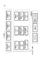
- FIG. 2 is a block diagram showing each functional unit and circuit configuration.
- FIG. 2 is a block diagram showing each functional unit and circuit configuration.
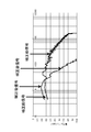
- FIG. 2 is a block diagram showing each functional unit and circuit configuration. It is a figure which shows the frequency characteristic of the supply signal which is a signal before correction
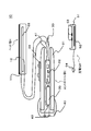
- FIG. 1 is a cross-sectional view showing a first structural example of a massage device 10 according to the present embodiment.
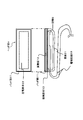
- FIG. 2 is a cross-sectional view and a plan view showing a second structural example of the massage device 10 according to the present embodiment.
- the massage device 10 may be roughly divided into three members.
- the first is a head section H having a vibration source.
- the second part is an operation part, that is, a control part C.
- the third is a charging stand D which is unnecessary for a dry battery, for example, but is convenient for a rechargeable battery.
- the head section H includes a pad section 11, a diaphragm 12, and a piezoelectric element 22.
- the pad portion 11 is, for example, a pad made of silicone resin having a thickness of about 0.1 to 2 mm. Basically, an adhesive sheet or a seal member may be used as long as it is a pad that is in close contact with human skin, and any material and shape may be used.
- the pad part 11 should just cover the diaphragm 12 widely, and should just stick on skin. Both ends of the piezoelectric element 22 have a smaller amplitude than the center. Therefore, the amplitude of the diaphragm 12 is smaller at both ends than at the center.
- the pad section 11 is not essential.
- the head portion H may be arranged and held between a skin tightening member such as a sock or a face mask and the skin. In such a case, the pad portion 11 is not essential.
- the diaphragm 12 may be made of a plastic material such as acrylic or polycarbonate, or glass. Alternatively, a thin metal plate such as aluminum, stainless steel, and duralumin may be used. As an example, the diaphragm 12 has a surface on which the pad portion 11 is provided with a vertical dimension of 15 to 35 mm, a horizontal dimension of 8 to 15 mm, and a thickness perpendicular to the preceding surface includes the thickness of the piezoelectric element 22. And may be 2 to 10 mm.
- a piezoelectric element 22 is embedded in the diaphragm 12.
- the diaphragm 12 only needs to have a plate-like portion on which the pad portion 11 can be arranged, and is not necessarily limited to a plate-like portion as a whole.
- the piezoelectric element 22 has a plate shape, and the largest surface (hereinafter, referred to as a first surface) is arranged to face the surface on the pad portion 11 side.
- the vertical dimension of the first surface may be approximately 0.5 to 0.9 times the vertical dimension (15 to 35 mm) of the hole-side surface.
- the lateral dimension of the first surface of the piezoelectric element 22 may be approximately 0.5 to 0.9 times the lateral dimension (5 to 15 mm) of the hole-side surface.
- the thickness of the piezoelectric element 22 may be about 0.3 to 2.0 mm.
- the piezoelectric element 22 is an element that expands and contracts or bends (curves) in accordance with the electromechanical coupling coefficient of a constituent material when a supply signal (voltage) is applied. These elements are made of, for example, ceramics or quartz.
- the piezoelectric element 22 may be a unimorph, bimorph, or multilayer piezoelectric element.
- the stacked piezoelectric element includes a stacked unimorph element in which unimorphs are stacked (for example, about 16 to 44 layers) or a stacked bimorph element in which bimorphs are stacked (for example, about 16 to 44 layers). It is.
- the laminated piezoelectric element is composed of a laminated structure of a plurality of dielectric layers made of, for example, PZT (lead zirconate titanate) and electrode layers disposed between the plurality of dielectric layers.
- the piezoelectric element 22 is curved in the thickness direction by the first surface extending in the vertical direction and the surface opposite to the first surface contracting in the vertical direction. .
- the first surface side shrinks in the vertical direction at the same time, and at the same time, the surface opposite to the first surface extends in the vertical direction, thereby bending in the thickness direction to the opposite side from the previous direction. I do. Vibration is generated by repeating this.
- an electrode wiring 33 connected to the piezoelectric element 22 is connected.
- the piezoelectric element 22 bends according to a supply signal described later.
- the vibrating plate 12 vibrates so as to bend in accordance with the bending of the piezoelectric element 22.
- the diaphragm 12 massages the skin directly or indirectly through a cloth or the like.
- the soft tissue and the bone tissue of the user may shake and listen to music. it can. That is, the music may be listened to with the same head portion H while obtaining the massage effect.
- the control unit C may include a housing 31 serving as a handle, a board 32 on which a control system, a memory, and the like are mounted, the electrode wiring 33, the cap unit 40, the operation unit 34, and the battery 35.
- the control unit C is an operation unit operated by the user while holding it.
- the housing 31 of the control section C has, for example, a tubular shape so as to be easily held. It is not essential that it be cylindrical, and it may be plate-like, as in many remote controllers. Further, it has a function as a housing for housing the substrate 32, the battery 35, and the like inside.
- the housing 31 may be made of a resin material such as plastic, like the diaphragm 12. Alternatively, the housing 31 may be made of a metal material such as aluminum or stainless steel, or tempered glass.
- the length of the control part C is, for example, about 5 cm to 25 cm.
- a space such as the substrate 32 may be closed.
- the cap portion 40 side the cap portion 40 itself presses the housing 31 similarly to the packing 41, and a waterproof structure is realized.
- the portion of the electrode wiring 33 is also waterproofed by the packing 41. In this way, the massager 10 can be used while taking a bath. Note that waterproofing is not always essential.
- the substrate 32 can be stored in a cylindrical internal space having a waterproof structure.
- the functional units and the circuit configuration of the control unit C shown in FIGS. 3 to 5 are mounted on the board 32.
- a signal generation unit 36, a drive amplifier 37, a memory 38, and the like are mounted on the substrate 32.
- the operation unit 34 may include a power switch (for example, a button switch) for switching ON / OFF of the massager 10 and an adjustment switch (for example, a + button and a-button) for adjusting the volume. These switches are arranged on the outer surface of the housing 31. The user can operate each switch from outside the housing 31. For example, a waterproof sheet may be attached to the outer surface of the housing 31, and these switches may be provided inside the waterproof sheet.
- the battery 35 is housed inside the housing 31. Then, the power supplied from the electrode pad 43 is stored, and the power is supplied to the substrate 32 according to a user operation.
- the battery 35 may be a dry battery.
- the cap section 40 is attached to the end of the control section C.
- the cap 40 together with the packing 41 seals the internal space where the battery 35 and the substrate 32 are arranged.
- an electrode pad 43 is provided on the surface exposed on the surface of the cap portion 40.
- the electrode pad 43 forms a part of a power line circuit that transmits power from the electrode pad 53 of the charging stand D to the battery 35.
- the charging stand D includes a housing 51, a substrate 52, an electrode pad 53, and a plug 54.
- the housing 51 of the charging stand D has a flat main surface on which the control unit C can be mounted.
- An electrode pad 53 is arranged on the main surface, and is electrically connected to the electrode pad 43 of the control unit C.
- a substrate 52 is disposed inside the housing 51, and converts power from a commercial power supply from the plug 54 from AC to DC, and has a function of transforming DC power.
- FIG. 1 The difference from the first structure example of FIG. 1 is particularly the structure of the head portion H.
- the second structure example includes the pad portion 11, the vibration plate 12, the adhesive member 13, the housing 21, the piezoelectric element 22, the electrode wiring 33, and the like.
- the piezoelectric element 22 is joined to the vibration plate 12 via an adhesive member 13.
- the vibration plate 12 is also a support member for the piezoelectric element 22 and a lid member for the housing 21.
- the piezoelectric element 22 causes the diaphragm 12 to bend directly.
- the depth of the concave portion of the housing 21 is such that the maximum amplitude when the piezoelectric element 22 is bent, the thickness of the piezoelectric element 22, the thickness of the adhesive member 13, It is designed by calculating shrinkage.
- the charging stand D has a plug 54 connected to a commercial power supply of, for example, 100 V, 1.5 A, 50/60 Hz.
- the electric power supplied from the plug 54 is converted to an appropriate voltage, for example, DC power of 5 V to 20 V, 1 A to 5 A, through a rectifier and a transformer mounted on the substrate 52.
- DC power from the substrate 52 is stored in the battery 35 via the electrode pads 53 and 43.
- the control unit C includes an electrode pad 43, an operation unit 34, a battery 35, a memory 38, a signal generation unit 36, a drive amplifier 37, an electrode wiring 33, and the like.
- the operation unit 34 may include an ON / OFF switch circuit for the massage device 10 and a circuit for adjusting the volume and the like. Further, a switch circuit for music selection may be provided.
- the battery 35 may include a charging circuit and an overcharge prevention circuit.
- the memory 38 stores a signal for driving the piezoelectric element 22.
- a signal including a signal having a predetermined frequency band in the audible range that is, a signal having a continuous spread which is not discrete at frequencies in the audible range is stored.
- This non-discrete signal is, for example, an analog or digital audio signal.
- the audio signal may include a music signal or human conversation data, a singing voice, and the like.
- a signal that presents only a single frequency which is a so-called pure tone in the field of sound, or a drive signal for driving a motor or the like at a single rotation speed is a non-discrete discrete signal. Is not included in the signal.
- a signal consisting of only a plurality of pure tones having only two A's in the above equation is not included because it is discrete. For example, a signal consisting only of a pure tone of 200 Hz and a pure tone of 10 kHz is not included in the non-discrete signal. Because each is a pure tone and discrete.
- the signal stored in the memory 38 may further include an ultrasonic signal corresponding to a frequency of, for example, 20 kHz to 100 kHz.
- the signal stored in the memory 38 may be encoded and compressed.
- the memory 38 for storing these signals may be a nonvolatile memory.
- an SD memory card (SDHC, SDXC,...) Or the like may be used as a removable memory inside by removing the cap section 40.
- the music may be written in the memory 38 by a personal computer or a smartphone, so that the user can reproduce the favorite music on the massage device 10.
- the signal generator 36 converts a signal recorded in the memory 38 into a supply signal to be supplied to the piezoelectric element 22. In some cases, conversion is not particularly necessary.
- the signal is supplied to the piezoelectric element 22 via the drive amplifier 37, the electrode wiring 33, and the like after a predetermined frequency band is reinforced. Before input to the piezoelectric element 22, the signal may pass through the drive amplifier 37, the gain correction unit 60, the booster circuit 61, and the LPF (low-pass filter) 62.
- the booster circuit 61 may be arranged behind an LPF (low-pass filter) 62.
- the supply signal compounded from the signal generator 36 branches into a right audio signal and a left audio signal.
- the right audio signal and the left audio signal are supplied to respective drive amplifiers 37R and 37L.
- the drive amplifiers 37R and 37L amplify the signals to predetermined strengths and supply signals to the booster circuits 611, 612, 613 and 614.
- the supply signals boosted by the respective booster circuits 611, 612, 613, 614 are supplied to the respective piezoelectric elements 221, 222, 223, 224.
- the four heads H corresponding to the four piezoelectric elements 221, 222, 223, and 224 may be respectively applied to different places.
- the piezoelectric element 221 is located near the right ear, and the piezoelectric element 223 is located near the left ear.
- the remaining piezoelectric elements 222 and 224 may be applied to a portion to be applied as a massager.
- the vicinity of the ear includes, for example, an auricle, an tragus, an antitragus, a bulge of a temporal bone, a zygomatic process, and the like. Also, it may be applied to the forehead or the mandible, etc., not near the ear.
- the combination of the above-described booster circuits 611, 612, 613, 614 and the piezoelectric elements 221, 222, 223, 224 is not limited to four, but may be further increased. In this case, the drive amplifier 37 may be branched.
- FIG. 5 shows an example of the provision.
- the signal generator 36 combines the right audio signal and the left audio signal to obtain a massage signal.
- the right audio signal and the left audio signal are supplied to the respective drive amplifiers 37R and 37L.
- the massage signal is supplied to the drive amplifier 37M.
- the drive amplifiers 37R, 37L, and 37M amplify the signal to a predetermined strength.
- the right audio signal and the left audio signal are supplied to the respective piezoelectric elements 221 and 222 via the respective boosting circuits 611 and 612.
- the massage signal is supplied from the drive amplifier 37M to the gain correction unit 60 as a pre-correction signal.
- the gain correction unit 60 amplifies the original signal by about 12 dB. Then, after boosting to a predetermined voltage value by the booster circuits 613 and 614, the signal of 200 Hz or less is gradually reduced by the LPFs (low-pass filters) 623 and 624 to obtain the corrected signal shown in FIG. This signal is supplied to the piezoelectric elements 223 and 224 for massage.
- the booster circuit 61 may be disposed behind an LPF (low-pass filter) 62.
- Each of the LPFs 623 and 624 supplies an unnecessary audio signal to the massage piezoelectric elements 223 and 224 to play a role in making interference less likely to occur, but may be omitted. For example, when interference is unlikely to occur due to the mounting position of the head portion H or the power of the piezoelectric element 22, this is unnecessary. It is to be noted that this is an example of a case where it is desired to use a low frequency of 200 Hz or less as a signal for massage. When it is desired to apply an ultrasonic signal as a massage signal, the LPF 62 may not be provided. Note that the setting of the LPF 62 may be set to 300 Hz or less.
- the signal supplied to the piezoelectric element 22 is called a supply signal.
- the supply signal also includes a signal that is continuous in a predetermined range in frequency characteristics, that is, a non-discrete signal in a predetermined range, like the non-discrete signal among the signals recorded in the memory 38 described above. Will be.
- the pre-correction signal is a signal for voice having non-discrete and flat frequency characteristics up to more than 10 kHz.
- the pre-correction signal is supplied as an audio signal to the booster circuit 61 and the piezoelectric element 22 via the drive amplifier 37.
- a post-correction signal in which the frequency characteristics in a low frequency band, in this case, 200 Hz or less, in comparison with the pre-correction signal, is enhanced by approximately 12 dB may be supplied to the piezoelectric element 22.
- the frequency band to be enhanced is corrected by the gain correction unit 60 shown in FIG. May be corrected and supplied to the piezoelectric element 22.
- the corrected signal itself may be stored in the memory 38 from the beginning.
- the volume or the power of massage may be operated by switching the mode of the volume adjustment switch of the operation unit 34.
- the mode may be switched by, for example, long pressing and short pressing of the power switch.
- a volume adjustment mode and a partial intensity adjustment mode for massage may be provided.
- the adjustment switch is operated in the volume adjustment mode, the magnitude of the power supplied to the piezoelectric element 22 is changed irrespective of the specific frequency so that the volume of the whole music is increased.
- the associated piezoelectric element 22 goes up or down irrespective of the frequency, both in volume and in the intensity of the massage.
- the magnitude of the power supplied to the piezoelectric element 22 is changed only for a specific frequency band, for example, as in the corrected signal in FIG.
- the adjustment method is not limited to this. These may be combined.
- a continuous signal that is not a delta function and is not discrete is supplied to the piezoelectric element 22 in a predetermined frequency characteristic range in the audible range (from 10 Hz to 20 kHz). May be.
- music can be heard, for example, using music including vibrations of various frequencies in the audible range as a supply signal. Also, by changing the music, vibrations in various frequency bands can be obtained. You may be able to massage while listening to your favorite music.
- the piezoelectric element 22 may vibrate not only in the audible range (from 10 Hz to 20 kHz) but also in the ultrasonic band (20 kHz or more).
- vibration around 50 kHz may be used.
- massage by ultrasonic vibration becomes possible.
- the signal giving the ultrasonic vibration may be a pure tone or a discrete signal.
- a continuous or non-discrete signal may be used.
- the piezoelectric element 22 is embedded in the vibration plate 12, when the piezoelectric element 22 is bent, the vibration plate 12 is also bent. By repeating this bending alternately in accordance with the frequency of upward convex and downward convex, the diaphragm 12 vibrates and is used as a massager. At the same time, a sound corresponding to the frequency is also generated. In other words, you can listen to a song or voice.
- the piezoelectric element 22 is embedded in a resin material made of acrylic or the like that constitutes the diaphragm 12. Since this structure is simple, there is an advantage that a waterproof structure around the piezoelectric element 22 can be easily realized.
- the piezoelectric element 22 is attached to the diaphragm 12 via the adhesive member 13. Therefore, when the piezoelectric element 22 bends, the diaphragm 12 also bends. By repeating this curve alternately according to the frequency of the upward convex and the downward convex, the diaphragm 12 vibrates and can be used as a massager. At the same time, a corresponding sound is generated. That is, a song or voice can be heard.
- the vibration source is formed by using the flat piezoelectric element 22, but the vibration source is not limited to this.
- a piezoelectric element called a stack type which is stacked in one direction and expands and contracts in one direction when each of the stacked layers becomes farther or closer, may be used.
- the invention is not limited to the piezoelectric element in the first place.
- the vibration source may be a coil-type vibration element.
- the coil-type vibrating element is attached to the lower part of the diaphragm 12, similarly to vibrating the cone in the vertical direction as when used in a speaker, and the vibrating element itself moves up and down along the vertical direction,
- the diaphragm 12 may be vibrated with this inertial force. With this, the vibration and the sound can be simultaneously expressed.
- the vibration plate 12 is curved by arranging a vibration source such as the piezoelectric element 22 in the head unit H instead of the control unit C, the soft tissue and the bone are applied when the massager 10 is applied to the skin.
- the user can hear the sound caused by the vibration of the user. Therefore, it is possible to enjoy music while receiving a massage, for example.
- the massage device 10 is applied to the user's head or the vicinity of the ear of the face, the cheek, the chin, the shoulder, the neck, the belly, the back, the leg thigh, the calf, the sole, the arm, the finger, and the like. May be used.
- the massager has a diaphragm, a head unit including a vibration source attached to the diaphragm, and a supply signal including a non-discrete signal in an audible range.
- a control unit including a circuit for supplying the vibration source.
- the vibration source causes the diaphragm to bend directly or indirectly.
- the vibration source vibrates and the diaphragm generates sound.
- the supply signal includes an ultrasonic band signal.
- the supply signal includes a music signal.
- the supply signal is supplied to the vibration source as an enhanced signal obtained by amplifying a predetermined frequency range by a drive amplifier.
- the head section is provided with a pad section.
- the music signal includes a right audio signal and a left audio signal, a right head unit is driven based on the right audio signal, and a left head unit is driven based on the left audio signal.
- a massage head is driven by a synthesized signal obtained by synthesizing the right audio signal and the left audio signal.
- the method of using the massager according to the present embodiment is to simultaneously vibrate the human body by vibrating the diaphragm of the massager, and vibrate the human body by vibrating the vibration plate to generate non-discrete sounds in the audible range. It is a method of generating.
Landscapes
- Health & Medical Sciences (AREA)
- Epidemiology (AREA)
- Pain & Pain Management (AREA)
- Physical Education & Sports Medicine (AREA)
- Rehabilitation Therapy (AREA)
- Life Sciences & Earth Sciences (AREA)
- Animal Behavior & Ethology (AREA)
- General Health & Medical Sciences (AREA)
- Public Health (AREA)
- Veterinary Medicine (AREA)
- Percussion Or Vibration Massage (AREA)
Abstract
マッサージ器は、振動板と、振動板にとりつけられた振動源と、を備えたヘッド部と、可聴域における非離散的な信号を含む供給信号を、振動源に供給する回路を備えたコントロール部と、を備える。
Description
本出願は、2018年7月24日に日本国において提出された特願2018-138811号の優先権を主張するものであり、この先の出願の開示全体を、ここに参照のために取り込む。
本開示は、マッサージ器及びマッサージ器の使用方法に関するものである。
例えば、マッサージ器は、圧電素子を用いるものが開示されている。
本開示のマッサージ器は、振動板と、振動板にとりつけられた振動源と、を備えたヘッド部と、可聴域における非離散的な信号を含む供給信号を、振動源に供給する回路を備えたコントロール部と、を備える。
以下、本開示の実施形態について説明する。
図1は本実施形態に係るマッサージ器10の第1の構造例を示す断面図である。図2は本実施形態に係るマッサージ器10の第2の構造例を示す断面図及び平面図である。マッサージ器10は、大きく分けて3つの部材からなっていてもよい。1つ目は振動源を備えたヘッド部Hである。2つ目は、操作をする部分、つまりコントロール部Cである。3つ目はたとえば乾電池の場合は不要であるが、充電可能なバッテリの場合に便利な充電台Dである。
以下、図1及び図2を用いて説明する。なお、把握の容易化のために、各図における縮尺は、適宜、変更している。
図1の第1の構造例を参照して説明する。ヘッド部Hは、パッド部11、振動板12、圧電素子22を備えている。
パッド部11は、たとえば、厚みが0.1~2mm程度のシリコーン樹脂製のパッドである。基本的には人間の肌に密着するパッドであれば、粘着シートまたはシール部材などでもよく、材料及び形状はなんでもよい。なお、パッド部11は、振動板12を幅広く覆い、肌に貼りつけばよい。圧電素子22の両端部は中央に比較して振幅が小さい。そのため、振動板12の振幅も中央に比較して両端部が小さい。なお、パッド部11は、必須ではない。たとえば靴下またはフェイスマスク等、肌を締め付けるものと肌との間にヘッド部Hを配置させて保持すればよく、このような場合パッド部11は必須ではない。
振動板12は、たとえばアクリルまたはポリカーボネート等のプラスティック素材、あるいはガラスからなっていてもよい。あるいはアルミニウムまたはステンレス、ジェラルミン等の金属薄板でもよい。この振動板12は、一例として、パッド部11が設けられる面の縦の寸法が15~35mm、横の寸法が8~15mm、先の面に直交する厚みが、圧電素子22の厚みを含んで、2~10mmであってもよい。
振動板12の内部には、圧電素子22が埋め込まれている。なお、振動板12は、パッド部11を配置できる板状の部分があればよく、必ずしも全体が板状であるものに限定されない。
圧電素子22は、板状をなしており、最も大きな面(以下、第1面という)が先のパッド部11側の面に対向して配置されている。そして、第1面の縦の寸法は、穴側の面の縦の寸法(15~35mm)のおおよそ0.5倍~0.9倍であってもよい。圧電素子22の第1面の横の寸法は、穴側の面の横の寸法(5~15mm)のおおよそ0.5倍~0.9倍であってもよい。圧電素子22の厚みは、おおよそ0.3~2.0mm程度であってもよい。
圧電素子22は、供給信号(電圧)を印加することで、構成材料の電気機械結合係数に従い伸縮または屈曲(湾曲)する素子である。これらの素子は、例えばセラミック製または水晶からなるものが用いられる。圧電素子22は、ユニモルフ、バイモルフまたは積層型の圧電素子であってよい。積層型の圧電素子には、ユニモルフを積層した(たとえば16層~44層程度積層した)積層型ユニモルフ素子、またはバイモルフを積層した(たとえば16層~44層程度積層した)積層型バイモルフ素子が含まれる。積層型の圧電素子は、例えばPZT(チタン酸ジルコン酸鉛)からなる複数の誘電体層と、該複数の誘電体層間に配置された電極層との積層構造体から構成される。圧電素子22は、まずは、第1面側が先の縦の方向に沿って伸びると同時に、第1面とは逆側の面が先の縦の方向に沿って縮むことにより、厚み方向に湾曲する。次に第1面側が先の縦の方向に沿って縮むと同時に、第1面とは逆側の面が先の縦の方向に沿って伸びることにより、厚み方向に先ほどとは逆側に湾曲する。これを繰り返すことによる振動を発生させる。また、圧電素子22につながる電極配線33が接続されている。
圧電素子22は、後述する供給信号に応じて湾曲する。そして圧電素子22の湾曲に応じて、振動板12が湾曲するように振動する。振動板12は、直接にあるいは布等を介して間接に肌をマッサージする。また、このヘッド部Hを耳の近辺(耳介または耳珠、あるいは側頭骨の乳突部または頬骨あたり)に当てた場合には、ユーザの軟部組織及び骨組織が震えて音楽を聴くこともできる。つまり、マッサージ効果を得ながら同じヘッド部Hで音楽を聴いてもよい。
コントロール部Cは、持ち手となる筐体31、制御系及びメモリ等を搭載した基板32、先の電極配線33、キャップ部40、操作部34、バッテリ35を含んで構成されてもよい。
コントロール部Cは、ユーザが手に持ちながら操作する操作部である。そのため、コントロール部Cの筐体31は、持ちやすいように、たとえば筒状をなしている。筒状であることは必須ではなく、多くのリモートコントローラのように板状でもよい。また、内部に基板32及びバッテリ35等を収納する筐体としての機能を有している。筐体31は、振動板12と同じように、プラスティック等の樹脂材料からなっていてもよい。あるいは筐体31は、アルミニウムもしくはステンレス等の金属材料または強化ガラスからなっていてもよい。コントロール部Cの長さは、たとえば5cm~25cm程度である。
使用される状態では、基板32等のある空間は密閉されていてもよい。たとえばキャップ部40側もキャップ部40自体がパッキン41と同様に筐体31を押圧しており、防水構造が実現されている。また、電極配線33の部位もパッキン41により防水が施されている。このようにすれば入浴しながらマッサージ器10を使用することもできる。なお、防水は必ずしも必須ではない。
基板32は、防水構造が実現された筒状の内部の空間に収納できる。基板32には、図3~図5にあらわされたコントロール部Cの各機能部及び回路構成が搭載される。たとえば、基板32には、信号生成部36、駆動アンプ37、メモリ38などが搭載される。
電極配線33等を通じて、圧電素子22に駆動するための供給信号が供給される。供給信号はたとえば図6のような周波数特性を持つ。なお図6の例に限られない。操作部34は、マッサージ器10のON・OFFを切り替える電源スイッチ(たとえばボタンスイッチ)と、音量調整する調整スイッチ(たとえば+ボタン・-ボタン)とを含んでもよい。これらのスイッチは筐体31の外側の面に配置されている。ユーザが筐体31の外側から各スイッチを操作可能である。たとえば、筐体31の外側表面に防水シートを貼付し、その内側にこれらのスイッチが設けられてもよい。
バッテリ35は、筐体31の内部に収納されている。そして電極パッド43から供給される電力を蓄えるとともに、ユーザの操作に応じて基板32へと電力を供給する。バッテリ35は乾電池でもよい。
キャップ部40は、コントロール部Cの端部に取り付けられる。キャップ部40は、パッキン41とともに、バッテリ35及び基板32が配置されている内部の空間を密閉する。また、キャップ部40の表面に露出する側の面には、電極パッド43が設けられている。
電極パッド43は、充電台Dの電極パッド53からの電力をバッテリ35へと伝達する電力線回路の一部を構成する。
充電台Dは、筐体51、基板52、電極パッド53及びプラグ54を備える。充電台Dの筐体51は、コントロール部Cを搭載可能な平板上の主面を備える。主面には電極パッド53が配置されており、コントロール部Cの電極パッド43と電気的に接続される。筐体51の内部には、基板52が配置されており、プラグ54からの商用電源からの電力を交流から直流に変換し、また、直流となった電力の変圧機能を備える。
次に図2を参照しながら第2の構造例を説明する。特に図1との変更点を中心に説明する。図1の第1の構造例と異なる点は特にヘッド部Hの構造である。
第2の構造例は、パッド部11、振動板12、接着部材13、筐体21、圧電素子22、電極配線33などからなる。圧電素子22は、振動板12に接着部材13を介して接合されている。そして、振動板12は、圧電素子22の支持部材でもあり、また筐体21の蓋部材にもなっている。圧電素子22が振動板12を直に湾曲させる。筐体21の凹部の深さは、湾曲を干渉しないだけの深さを持つ空間Sを構成するように、圧電素子22の湾曲時の最大振幅、圧電素子22の厚み、接着部材13の厚み及び収縮率を計算して設計されている。
次に図3の実施例にて回路構成等の電気的な接続関係を含めて説明する。充電台Dは、たとえば100V、1.5A、50/60Hzの商用電源に接続されるプラグ54をそなえる。プラグ54から供給される電力は、基板52に搭載された整流器及び変圧器等を通して、適切な電圧、たとえば5V~20V、1A~5Aの直流電力に変換される。基板52からの直流電力は、電極パッド53,43を介して、バッテリ35に蓄積される。
コントロール部Cは、電極パッド43、操作部34、バッテリ35、メモリ38、信号生成部36、駆動アンプ37、電極配線33等を含んで構成される。
操作部34は、マッサージ器10のON・OFF切り替えスイッチ回路と、音量等の調整回路とを含んでもよい。さらには、楽曲選択のスイッチ回路を備えていてもよい。バッテリ35は、充電回路及び過充電防止回路を備えていてもよい。
メモリ38は、圧電素子22を駆動するための信号を記憶する。具体的には、可聴域において所定の周波数帯域からなる信号、すなわち可聴域の周波数において離散的でない、連続的な広がりを有する信号を含んで記憶する。この非離散的な信号とは、周波数特性を示すグラフにおいて、周波数F(Hz)=100×A : (Aは1~200の整数)とあらわした時に、暗騒音をのぞいた有意な信号が検出されるAが3つ以上あるものをいう。この非離散的な信号は、たとえばアナログまたはデジタルの音声信号である。音声信号には、楽曲信号または人間の会話データ、歌声等が含まれてよい。ただし、音響の分野でいわゆる純音(pure tone)といわれるような単一の周波数だけを提示する信号、またはたとえばモータ等に単一の回転数で駆動させるための駆動信号はここでいう非離散的な信号には含まれない。また、上記の式のAが2つしかない複数の純音だけからなる信号も離散的であるため、含まれない。たとえば200Hzの純音と10kHzの純音だけからなる信号も非離散的な信号には含まれない。それぞれが純音であり離散的だからである。
また、メモリ38に記憶される信号は、たとえば20kHzから100kHzまでの周波数に対応する超音波信号をさらに含んでいてもよい。またメモリ38に記憶された信号は、符号化圧縮がされていてもよい。
これらの信号を記憶するためのメモリ38は、不揮発性メモリであってもよい。たとえば、キャップ部40を取り外して、内部に取り外し可能なメモリとして、たとえばSDメモリカード(SDHC、SDXC、・・・)等でもよい。このSDメモリカードの場合、パーソナルコンピュータまたはスマートフォンにより、楽曲をメモリ38に書き込むことで、ユーザが好みの楽曲をマッサージ器10にて再生することができるようにしてもよい。
信号生成部36は、メモリ38に記録された信号を圧電素子22に供給する供給信号に変換する。なお、特に変換不要な場合もある。信号は、所定の周波数帯の強化等が行われたのち、駆動アンプ37、電極配線33等を経て圧電素子22へと供給される。なお、圧電素子22に入力する前に、駆動アンプ37からゲイン補正部60、昇圧回路61、LPF(ローパスフィルタ)62を経る場合もある。昇圧回路61は、LPF(ローパスフィルタ)62の後ろに配置してもよい。
たとえば信号生成部36から複合化された供給信号は、図4に示すようなステレオの場合、右用音声信号と左用音声信号とで分岐する。右用音声信号及び左用音声信号はそれぞれの駆動アンプ37R,37Lに供給される。駆動アンプ37R,37Lは、それぞれの所定の強さに増幅を行い、昇圧回路611,612,613,614へと信号を供給する。それぞれの昇圧回路611,612,613,614にて昇圧された供給信号は、各圧電素子221,222,223,224へと供給される。なお、4つの圧電素子221,222,223,224に対応する4つのヘッド部Hをそれぞれ別の箇所に充ててもよいし、たとえば圧電素子221を右耳近傍に、圧電素子223を左耳近傍にあてがい、残りの圧電素子222,224をマッサージ器としてあてがいたい部位にあてがってもよい。なお、耳近傍には、たとえば耳介、耳珠、対耳珠、側頭骨の乳突部、頬骨突起等が含まれる。また、耳近傍ではないが額または下顎骨等にあててもよい。上記した昇圧回路611,612,613,614と圧電素子221,222,223,224の組み合わせは4つではなく、さらにふやしてもよい。この場合、駆動アンプ37から分岐させればよい。
次に、回路構成の別の例を説明する。たとえば信号生成部36から複合化された供給信号は、図4に示すようなステレオの場合、右用音声信号と左用音声信号とで分岐するが、さらにマッサージ用の信号(マッサージ用信号)を別途備える例を図5に示す。信号生成部36は、右用音声信号及び左用音声信号を合成してマッサージ用信号を得る。その後、右用音声信号及び左用音声信号は、それぞれの駆動アンプ37R,37Lに供給される。マッサージ用信号は、駆動アンプ37Mに供給される。駆動アンプ37R,37L、37Mは、それぞれの所定の強さに信号を増幅する。その後、右用音声信号及び左用音声信号は、それぞれの昇圧回路611,612を経て、それぞれの圧電素子221,222へと供給される。
マッサージ用信号が、補正前信号として、駆動アンプ37Mからゲイン補正部60に供給される。ゲイン補正部60は、元の信号よりも12dB程度、増幅している。その後、昇圧回路613,614により所定の電圧値まで昇圧したのち、LPF(ローパスフィルタ)623,624により200Hz以下の信号を漸次低減して、図6に示す補正後信号を得る。この信号をマッサージ用の圧電素子223,224に供給する。なお、昇圧回路61は、LPF(ローパスフィルタ)62の後ろに配置してもよい。各LPF623,624は、マッサージ用の圧電素子223,224に余計な音声信号を供給して干渉が生じにくくする役割を果たすが、必ずしもなくともよい。たとえばヘッド部Hの取り付け位置または圧電素子22のパワーにより干渉が生じにくい場合は、不要である。なお、ここではマッサージ用の信号として、200Hz以下の低域を使用したい場合の例である。マッサージ用の信号として、超音波信号を印加したい場合は、LPF62はなくともよい。なお、LPF62の設定は300Hz以下に設定してもよい。
次に、圧電素子22に供給する信号の周波数特性について説明する。上述したとおり、圧電素子22に供給される信号を供給信号とよぶ。たとえば供給信号も、上記のメモリ38に記録された信号のうち、非離散的な信号と同様に、周波数特性において所定の範囲で連続的な信号、すなわち所定の範囲で非離散的な信号を含むことになる。たとえば図6に示す供給信号のうち、補正前信号は、10kHz超までの非離散的且つ平坦な周波数特性を有する音声用の信号である。この補正前信号は、音声信号として駆動アンプ37を経て昇圧回路61、圧電素子22へと供給される。
また、この補正前信号と比較して、低周波数帯、この場合は200Hz以下の周波数特性をおおよそ12dBだけ強化した補正後信号を、圧電素子22に供給してもよい。この低周波数帯の信号パワーを局所的に上げることにより、マッサージ効果の向上が期待される。なお、この補正後信号は、メモリ38から出力された補正前信号を、駆動アンプ37にかける際に、強化したい周波数帯域を図5に示すゲイン補正部60にて強める補正またはLPF62にかけて余分な信号をカットする補正を行い、これを圧電素子22に供給してもよい。もちろん、最初から補正後信号自体をメモリ38に記憶しておいてもよい。
なお、音量またはマッサージのパワーは、操作部34の音量の調整スイッチのモードを切り替えることにより、操作されてもよい。モードの切り替えは、たとえば電源スイッチの長押しと短押しとで行ってもよい。具体的には、音量調整モードと、マッサージの部分的な強度の調整モードとを備えていてもよい。そして、音量調整モードのときに、調整スイッチが操作されると、楽曲全体のボリュームが上がるように、特定の周波数に関係なく、圧電素子22に供給するパワーの大小が変更される。この場合、関連する圧電素子22は、音量もマッサージの強さも周波数に関係なくアップあるいはダウンする。
一方、マッサージの強度調整モードの場合は、たとえば図6の補正後信号のように、特定の周波数帯に対してだけ、圧電素子22に供給するパワーの大小が変更される。もちろん、調整方法はこれに限られない。これらをくみあわせてもよい。
図6に示したように、圧電素子22には、可聴域(10Hzから20kHzまで)の所定の周波数特性の範囲において、デルタ関数的ではなく、且つ離散的ではない、連続的な信号が供給されてよい。これにより、たとえば可聴域の様々な周波数の振動を含む楽曲を供給信号として、音楽を聞かせることもできる。また、曲を変更することで、様々な周波数帯域の振動を得ることもできる。好みの音楽を聴きながらマッサージができてもよい。
さらには、圧電素子22は、可聴域(10Hzから20kHzまで)に加え、超音波帯(20kHz以上)でも振動させてもよい。たとえば可聴域(10Hzから20kHzまで)の連続的な振動に加え、50kHz付近で振動してもよい。この場合、超音波振動によるマッサージが可能となる。超音波振動を与える信号は純音であってもよいし、また離散的な信号でもよい。もちろん連続的、非離散的な信号でもよい。
次に、ヘッド部Hの動作について説明する。
図1の第1の構造例では、圧電素子22が振動板12に埋め込まれているため、圧電素子22が湾曲すると、振動板12も湾曲する。この湾曲を上に凸、下に凸と周波数に応じて交互に繰り返すことで振動板12が振動してマッサージ器として使用されることとなる。同時に周波数に対応する音も発生する。つまり曲または声を聴かせることもできる。圧電素子22を、振動板12を構成するアクリル等からなる樹脂材に埋め込んでいる。この構造は単純であるため、圧電素子22の周辺の防水構造が容易に実現できるメリットがある。
図2の第2の構造例では、圧電素子22は接着部材13を介して振動板12に貼り付けられている。このため、圧電素子22が湾曲すると、振動板12も湾曲する。この湾曲を上に凸、下に凸と周波数に応じて交互に繰り返すことで振動板12が振動してマッサージ器として使用できることとなる。同時に対応する音声も発生する。すなわち曲または声を聴かせることもできる。
なお、上述したいくつかの例では平板状の圧電素子22を用いて振動源としていたが、これに限られない。たとえば一方向に積層されて、各積層された層が遠くなったり近くなったりすることにより前記一方向に伸び縮みをするスタック型と呼ばれる圧電素子を用いてもよい。また、そもそも圧電素子に限られない。たとえば振動源は、コイル型の振動素子でもよい。コイル型の振動素子は、スピーカで使用されるときのようにコーンを上下方向に振動させるのと同様に、振動板12の下部に取りつけられ、上下方向に沿って振動素子自体が上下移動し、この慣性力をもって、振動板12を振動させてもよい。これによっても振動と音声とを同時に発現させることができる。
本開示では、コントロール部Cではなく、ヘッド部Hに圧電素子22等の振動源を配置して振動板12を湾曲させているために、肌にマッサージ器10を当てたときに軟部組織及び骨が振動することに起因する音をユーザが聴くことができる。そのため、たとえばマッサージを受けながら同時に音楽を楽しむこともできる。
上記した各実施例においては、ユーザの頭または顔の耳近傍、頬、顎、肩、首筋、腹、背中、脚の太もも、ふくらはぎ、足の裏、腕、指等にあててマッサージ器10を使用してもよい。
上述のように、本実施形態に係るマッサージ器は、振動板と、前記振動板にとりつけられた振動源と、を備えたヘッド部と、可聴域における非離散的な信号を含む供給信号を、前記振動源に供給する回路を備えたコントロール部と、を備える。
一実施例において、前記振動源は前記振動板を直にあるいは間接的に湾曲させる。
一実施例において、前記振動源が振動するとともに、前記振動板から音声が発生する。
一実施例において、前記供給信号には、超音波帯域の信号が含まれる。
一実施例において、前記供給信号には、楽曲信号が含まれる。
一実施例において、前記供給信号は駆動アンプにより所定の周波数域を増幅した強化信号として前記振動源に供給される。
一実施例において、前記ヘッド部には、パッド部が設けられている。
一実施例において、前記楽曲信号は右用音声信号及び左用音声信号を含み、前記右用音声信号に基づき右用のヘッド部を駆動させ、前記左用音声信号に基づき左用のヘッド部を駆動させ、前記右用音声信号及び前記左用音声信号を合成して得られた合成信号によりマッサージ用のヘッド部を駆動させる。
本実施形態に係るマッサージ器の使用方法は、マッサージ器の振動板を振動させて人体を振動させると同時に、前記振動板の振動により前記人体を振動させて、可聴域における非離散的な音声を発生させる、という方法である。
H・・・ヘッド部
S・・・空間
C・・・コントロール部
D・・・充電台
10・・・マッサージ器
11・・・パッド部
12・・・振動板
13・・・接着部材
21・・・筐体
22・・・圧電素子
221・・圧電素子
222・・圧電素子
223・・圧電素子
224・・圧電素子
31・・・筐体
32・・・基板
33・・・電極配線
34・・・操作部
35・・・バッテリ
36・・・信号生成部
37・・・駆動アンプ
37L・・駆動アンプ
37M・・駆動アンプ
37R・・駆動アンプ
38・・・メモリ
40・・・キャップ部
41・・・パッキン
43・・・電極パッド
51・・・筐体
52・・・基板
53・・・電極パッド
54・・・プラグ
60・・・ゲイン補正部
61・・・昇圧回路
612・・・昇圧回路
613・・・昇圧回路
614・・・昇圧回路
615・・・昇圧回路
62・・・LPF
623・・LPF
624・・LPF
S・・・空間
C・・・コントロール部
D・・・充電台
10・・・マッサージ器
11・・・パッド部
12・・・振動板
13・・・接着部材
21・・・筐体
22・・・圧電素子
221・・圧電素子
222・・圧電素子
223・・圧電素子
224・・圧電素子
31・・・筐体
32・・・基板
33・・・電極配線
34・・・操作部
35・・・バッテリ
36・・・信号生成部
37・・・駆動アンプ
37L・・駆動アンプ
37M・・駆動アンプ
37R・・駆動アンプ
38・・・メモリ
40・・・キャップ部
41・・・パッキン
43・・・電極パッド
51・・・筐体
52・・・基板
53・・・電極パッド
54・・・プラグ
60・・・ゲイン補正部
61・・・昇圧回路
612・・・昇圧回路
613・・・昇圧回路
614・・・昇圧回路
615・・・昇圧回路
62・・・LPF
623・・LPF
624・・LPF
Claims (9)
- 振動板と、前記振動板にとりつけられた振動源と、を備えたヘッド部と、可聴域における非離散的な信号を含む供給信号を、前記振動源に供給する回路を備えたコントロール部と、を備えたマッサージ器。
- 前記振動源は前記振動板を直にあるいは間接的に湾曲させる請求項1に記載のマッサージ器。
- 前記振動源が振動するとともに、前記振動板から音声が発生する請求項1に記載のマッサージ器。
- 前記供給信号には、超音波帯域の信号が含まれる請求項1に記載のマッサージ器。
- 前記供給信号には、楽曲信号が含まれる請求項1に記載のマッサージ器。
- 前記供給信号は駆動アンプにより所定の周波数域を増幅した強化信号として前記振動源に供給される請求項1に記載のマッサージ器。
- 前記ヘッド部には、パッド部が設けられている請求項1に記載のマッサージ器。
- 前記楽曲信号は右用音声信号及び左用音声信号を含み、前記右用音声信号に基づき右用のヘッド部を駆動させ、前記左用音声信号に基づき左用のヘッド部を駆動させ、前記右用音声信号及び前記左用音声信号を合成して得られた合成信号によりマッサージ用のヘッド部を駆動させる請求項5に記載のマッサージ器。
- マッサージ器の振動板を振動させて人体を振動させると同時に、前記振動板の振動により前記人体を振動させて、可聴域における非離散的な音声を発生させるマッサージ器の使用方法。
Applications Claiming Priority (2)
| Application Number | Priority Date | Filing Date | Title |
|---|---|---|---|
| JP2018-138811 | 2018-07-24 | ||
| JP2018138811A JP2020014612A (ja) | 2018-07-24 | 2018-07-24 | マッサージ器 |
Publications (1)
| Publication Number | Publication Date |
|---|---|
| WO2020021996A1 true WO2020021996A1 (ja) | 2020-01-30 |
Family
ID=69181047
Family Applications (1)
| Application Number | Title | Priority Date | Filing Date |
|---|---|---|---|
| PCT/JP2019/026309 Ceased WO2020021996A1 (ja) | 2018-07-24 | 2019-07-02 | マッサージ器及びマッサージ器の使用方法 |
Country Status (2)
| Country | Link |
|---|---|
| JP (1) | JP2020014612A (ja) |
| WO (1) | WO2020021996A1 (ja) |
Families Citing this family (1)
| Publication number | Priority date | Publication date | Assignee | Title |
|---|---|---|---|---|
| JP7619720B1 (ja) | 2024-03-08 | 2025-01-22 | Necプラットフォームズ株式会社 | 電源制御装置、情報処理装置、および電源制御方法 |
Citations (2)
| Publication number | Priority date | Publication date | Assignee | Title |
|---|---|---|---|---|
| JP2005348994A (ja) * | 2004-06-11 | 2005-12-22 | Koto Denshi Kk | 超音波マッサ−ジシ−トシステム。 |
| JP2015157034A (ja) * | 2014-02-25 | 2015-09-03 | 有限会社上山製作所 | マッサージ装置 |
Family Cites Families (4)
| Publication number | Priority date | Publication date | Assignee | Title |
|---|---|---|---|---|
| US4823042A (en) * | 1986-07-18 | 1989-04-18 | Rich-Mar Corporation | Sonic transducer and method for making the same |
| JPH0657343U (ja) * | 1993-01-22 | 1994-08-09 | 株式会社三協精機製作所 | あんま器 |
| JP2000140060A (ja) * | 1998-09-01 | 2000-05-23 | Mitsubishi Electric Corp | マッサ―ジ装置 |
| JP2012125405A (ja) * | 2010-12-15 | 2012-07-05 | Sunnyhealth Co Ltd | 歯茎マッサージ装置 |
-
2018
- 2018-07-24 JP JP2018138811A patent/JP2020014612A/ja active Pending
-
2019
- 2019-07-02 WO PCT/JP2019/026309 patent/WO2020021996A1/ja not_active Ceased
Patent Citations (2)
| Publication number | Priority date | Publication date | Assignee | Title |
|---|---|---|---|---|
| JP2005348994A (ja) * | 2004-06-11 | 2005-12-22 | Koto Denshi Kk | 超音波マッサ−ジシ−トシステム。 |
| JP2015157034A (ja) * | 2014-02-25 | 2015-09-03 | 有限会社上山製作所 | マッサージ装置 |
Also Published As
| Publication number | Publication date |
|---|---|
| JP2020014612A (ja) | 2020-01-30 |
Similar Documents
| Publication | Publication Date | Title |
|---|---|---|
| US9622000B2 (en) | Audio device | |
| US10904664B2 (en) | Device for generating chest-chamber acoustic resonance and delivering the resultant audio and haptic to headphones | |
| CN103874003B (zh) | 具有裸耳麦克风的骨传导听力装置 | |
| CN104159181B (zh) | 具有自主调校功能的助听方法及系统 | |
| JP7084529B2 (ja) | ブラシ及び交換部材 | |
| JP2009111820A (ja) | 骨伝導イヤホン | |
| CN103607674A (zh) | 头戴送受话器系统和方法 | |
| JP2013218248A (ja) | 電子機器 | |
| JP2007165938A (ja) | 受話装置 | |
| CN204014060U (zh) | 具有自主调校功能的助听装置及系统和应用 | |
| WO2013172019A1 (ja) | 電子機器 | |
| WO2017145521A1 (ja) | ウェアラブル装置 | |
| JPWO2009107305A1 (ja) | 電気音響変換器 | |
| JP2015109589A (ja) | イヤホン | |
| CN104053103B (zh) | 压电扬声器 | |
| JP6359804B2 (ja) | 音響機器 | |
| KR20110024636A (ko) | 압전 진동을 이용해 골전도 기능을 가지는 헤드폰 | |
| EP3827701B1 (en) | Brush, replacement member for brush, and method for using brush | |
| WO2020021996A1 (ja) | マッサージ器及びマッサージ器の使用方法 | |
| US20190110130A1 (en) | Audio device and audio system having audio device attached thereto | |
| JP6250950B2 (ja) | 音響機器 | |
| WO2014061646A1 (ja) | イヤホン | |
| CN108742010A (zh) | 一种基于骨传导的音乐枕头 | |
| CN115334406A (zh) | 音箱 | |
| JP2014096739A (ja) | イヤホン |
Legal Events
| Date | Code | Title | Description |
|---|---|---|---|
| 121 | Ep: the epo has been informed by wipo that ep was designated in this application |
Ref document number: 19842084 Country of ref document: EP Kind code of ref document: A1 |
|
| NENP | Non-entry into the national phase |
Ref country code: DE |
|
| 122 | Ep: pct application non-entry in european phase |
Ref document number: 19842084 Country of ref document: EP Kind code of ref document: A1 |