WO2020021668A1 - 天然ガス処理装置 - Google Patents
天然ガス処理装置 Download PDFInfo
- Publication number
- WO2020021668A1 WO2020021668A1 PCT/JP2018/027992 JP2018027992W WO2020021668A1 WO 2020021668 A1 WO2020021668 A1 WO 2020021668A1 JP 2018027992 W JP2018027992 W JP 2018027992W WO 2020021668 A1 WO2020021668 A1 WO 2020021668A1
- Authority
- WO
- WIPO (PCT)
- Prior art keywords
- natural gas
- fan
- air
- duct
- heat exchanger
- Prior art date
- Legal status (The legal status is an assumption and is not a legal conclusion. Google has not performed a legal analysis and makes no representation as to the accuracy of the status listed.)
- Ceased
Links
Images



Classifications
-
- F—MECHANICAL ENGINEERING; LIGHTING; HEATING; WEAPONS; BLASTING
- F28—HEAT EXCHANGE IN GENERAL
- F28D—HEAT-EXCHANGE APPARATUS, NOT PROVIDED FOR IN ANOTHER SUBCLASS, IN WHICH THE HEAT-EXCHANGE MEDIA DO NOT COME INTO DIRECT CONTACT
- F28D1/00—Heat-exchange apparatus having stationary conduit assemblies for one heat-exchange medium only, the media being in contact with different sides of the conduit wall, in which the other heat-exchange medium is a large body of fluid, e.g. domestic or motor car radiators
- F28D1/02—Heat-exchange apparatus having stationary conduit assemblies for one heat-exchange medium only, the media being in contact with different sides of the conduit wall, in which the other heat-exchange medium is a large body of fluid, e.g. domestic or motor car radiators with heat-exchange conduits immersed in the body of fluid
- F28D1/04—Heat-exchange apparatus having stationary conduit assemblies for one heat-exchange medium only, the media being in contact with different sides of the conduit wall, in which the other heat-exchange medium is a large body of fluid, e.g. domestic or motor car radiators with heat-exchange conduits immersed in the body of fluid with tubular conduits
Definitions
- the present invention relates to a natural gas processing apparatus provided with an air-cooled heat exchanger.
- Natural gas (NG: Natural Gas) produced from the wellhead is subjected to pre-treatment and liquefaction processing to separate impurity components such as acid gas and moisture, and then to storage and shipping facilities for demand. Be transported. In some cases, a process of recovering some high value-added components contained in natural gas is performed.
- the natural gas processing equipment that performs these processes includes an absorbent used to remove impurities, a refrigerant that cools natural gas, and cooling of various components (acid gas and light components) separated and recovered from natural gas.
- a large number of air-cooled heat exchangers hereinafter, also referred to as “ACHE: Air-Cooled Heat Exchanger” are provided.
- the ACHE cools the fluid to be cooled by using a rotary fan to take in cooling air and supply it to a tube bundle in which tubes through which the fluid flows are bundled.
- the ACHE is designed and manufactured so that a predetermined amount of heat can be taken from a fluid to be cooled at a designed flow rate under a preset temperature condition.
- Patent Literature 1 the upper end of a plate-shaped electric heating element which is disposed below a fan and through which a refrigerant flows flows from an opposing surface of the element to a suction port of a fan casing surrounding an outer peripheral portion of the fan.
- An air-cooled cooling tower provided with an extending current plate is described. Even if a rectifying plate is provided on the suction side of the fan casing as in the technique described in Patent Literature 1, it is not possible to affect a problem caused by the outlet side of the fan.
- the present invention has been made under such a background, and provides a technique for suppressing a decrease in airflow of an air-cooled heat exchanger provided in a natural gas processing apparatus.
- the natural gas processing device of the present invention is a natural gas processing device for processing natural gas,
- a tube bundle that bundles tubes through which a fluid to be cooled, which is a fluid handled by the natural gas liquefier, is provided on the upper side of the tube bundle, and cools the fluid to be cooled.
- the natural gas processing device may have the following features.
- a plurality of the stationary blades of the air-cooled heat exchanger are provided so as to radially spread from a central position in a plan view of the duct toward an inner wall surface of the duct.
- the air-cooled heat exchanger has a ratio H / D between the height H from the upper end position of the fan to the opening of the duct and the diameter D of the opening of the duct of 0.1 to 1.5.
- the number of the stationary blades to be installed is between 2 and 8.
- the fan of the air-cooled heat exchanger includes a plurality of moving blades, and the number of moving blades and the number of installed stationary blades are different.
- the number of moving blades provided in the fan of the air-cooled heat exchanger is larger than the number of installed stationary blades, the number of installed stationary blades is different from the divisor of the number of the moving blades.
- the number must be (D)
- the vanes of the air-cooled heat exchanger are curved so that the inclination with respect to the horizontal direction gradually increases from the lower end to the upper end along the rotation direction of the fan.
- the stationary blades of the air-cooled heat exchanger rectify the swirling flow, so that the vertical velocity of the cooling air discharged from the opening of the duct is within a range of 5 to 20 m / s. Being provided.
- the swirl flow is generated in the duct on the upper side of the fan of the air-cooled heat exchanger provided in the natural gas processing device, so that the swirl flow is rectified into a vertical flow. Energy loss due to the air flow can be suppressed, and a decrease in air volume can be suppressed.
- FIG. 3 is a first plan view of the ACHE.
- FIG. 3 is a second plan view of the ACHE. It is a partially broken perspective view of the ACHE. It is an operation
- FIG. 1A is a block diagram schematically illustrating a configuration of the NG liquefaction apparatus 1.
- the NG liquefaction apparatus 1 includes a pretreatment unit 11 that removes various impurities such as mercury, acid gas (hydrogen sulfide, mercaptan, carbon dioxide, etc.), moisture, and heavy components contained in NG produced from a well base.
- Liquefied natural gas (LNG) obtained by the NG liquefaction apparatus 1 is stored in an LNG tank 13 and then shipped outside via an LNG tanker or the like.
- the refrigerant used for liquefaction / subcooling of NG is a mixed refrigerant containing nitrogen, methane, ethane, propane, or the like.
- MR Mixed Refrigerant
- each refrigerant such as propane, ethylene, methane, ethane, and nitrogen is used as the refrigerant.
- the liquefied LNG may be supercooled using a nitrogen expander cycle in addition to the above-described refrigerant. In some cases, the temperature of the LNG is adjusted by vaporizing (end flashing) a part of the LNG.
- the liquefaction unit 12 heat exchange between NG and the above-described refrigerant is performed via a heat exchanger (not shown).
- the liquefaction unit 12 further includes a liquefaction refrigerant cycle 121 in which the refrigerant vaporized by the heat exchange is compressed by the compressor 31, then cooled and liquefied by the cooler, and supplied again to the liquefaction unit 12.
- an air-cooled heat exchanger (ACHE) 2 is used as these coolers.
- the cooler employing ACHE2 may be a condenser for condensing the compressed refrigerant, or a supercooler for subcooling the liquefied refrigerant.
- FIG. 1A which is a schematic diagram, only one set of the compressor 31 and the ACHE2 is shown in the liquefaction refrigerant cycle 121, but the set of the compressor 31 and the ACHE2 is connected in series according to the pressure stage of the refrigerant. May be provided in plurality. Further, a plurality of liquefaction refrigerant cycles 121 including the compressor 31 and the ACHE 2 may be provided in parallel with the liquefaction unit 12 in accordance with the amount of refrigerant handled.
- FIG. 1B is a block diagram schematically illustrating a configuration of an NG liquefaction apparatus 1 including a precooling unit 14 that cools NG before being liquefied using a precooling refrigerant.
- a pre-cooling refrigerant used for pre-cooling NG a propane simple refrigerant or a mixed refrigerant of ethane and propane is used.
- the pre-cooling unit 14 heat exchange between the NG and the pre-cooling refrigerant is performed via a heat exchanger (not shown). Further, the pre-cooling section 14 is provided with a pre-cooling refrigerant cycle 141 in which a refrigerant vaporized by heat exchange is compressed by the compressor 31, then cooled and liquefied by a cooler, and re-supplied to the pre-cooling section 14.
- ACHE2 is also used as these coolers.
- the cooler adopting ACHE2 may be any one of a cooler for reducing the temperature of the compressed refrigerant, a condenser for condensing the refrigerant, and a supercooler for supercooling the liquefied refrigerant.
- the NG liquefaction apparatus 1 shown in FIG. 1 (b) extracts a part of the pre-cooling refrigerant after liquefaction and super-cooling from the pre-cooling refrigerant cycle 141 and supplies the liquefied refrigerant before being supplied to the liquefaction unit 12. And a refrigerant cooling cycle 142 for cooling the refrigerant.
- the pre-cooling refrigerant flowing through the refrigerant cooling cycle 142 cools the liquefying refrigerant on the liquefaction refrigerant cycle 121 side with the cooler 32 and then returns to the inlet of the compressor 31 on the pre-cooling refrigerant cycle 141 side.
- a plurality of pre-cooling refrigerant cycles 141 including the compressor 31 and the ACHE 2 may be provided in parallel with the pre-cooling section 14. Further, a plurality of refrigerant cooling cycles 142 may be connected in parallel to the pre-cooling refrigerant cycle 141.
- the ACHE 2 is used for cooling the liquefaction refrigerant and the pre-cooling refrigerant described with reference to FIGS. 1A and 1B, and may be provided in various processes provided in the pretreatment unit 11. is there.
- ACHE2 may be employed as a condenser for condensing the vapor extracted from the top of the regeneration tower for the amine absorbing solution.
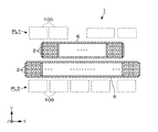
- FIG. 2 shows an example of a plot plan of the NG liquefaction apparatus 1.
- a group of facilities (equipment groups PL1, PL2) constituting the NG liquefaction apparatus 1 are arranged and arranged with the pipe rack 6 interposed therebetween.
- equipment groups PL1 and PL2 as equipment for various impurity removal processes constituting the pretreatment unit 11 and as equipment for the precooling unit 14 and the liquefaction unit 12, a tower tank, a heat exchanger, and a moving equipment as static equipment are used.
- a certain pump is provided.
- the broken line in FIG. 2 indicates the arrangement area 100 of these facilities.
- each pipe rack 6 is configured as an elongated rectangular frame structure as viewed from the upper surface side, and NG and various refrigerants (liquefied refrigerant and precooled refrigerant) exchanged between the devices constituting the above-described equipment groups PL1 and PL2. And a plurality of pipes 61 (an aggregate of the pipes 61) through which a fluid flows.
- refrigerants liquefied refrigerant and precooled refrigerant
- the number of ACHEs 2 provided in the pre-cooling refrigerant cycle 141 and the refrigerant cooling cycle 142 is large, and a condenser, a subcooler, a condenser, or the like may be configured using several to several tens of ACHEs 2. is there. For this reason, depending on the scale, there is an NG liquefaction apparatus 1 equipped with nearly 100 ACHEs 2 as a whole.
- the NG liquefaction apparatus 1 of the present example is configured such that, for example, three ACHEs 2 are arranged on the upper surface of a rectangular pipe rack 6 as viewed from the upper surface side along the short side direction of the rectangle to form a set. A large number of these sets of ACHE2 are arranged along the long side direction of the rectangle.
- FIG. 4 shows a configuration example of the suction-type ACHE 2.
- the ACHE 2 is a bundle of a large number of tubes 23 through which a fluid to be cooled (a fluid handled by the NG liquefaction apparatus 1: a liquefied refrigerant, a precooled refrigerant, and other fluids handled in the process of the pretreatment unit 11) flows. It includes a tube bundle 230 and the fan 22 disposed above the tube bundle 230.
- the tube bundle 230 is open on both upper and lower surfaces, and allows cooling air to flow upward from below through the gap between the adjacent tubes 23. Further, a frame constituting a side peripheral portion of the tube bundle 230 is fixed to an upper surface of a frame constituting the pipe rack 6.
- the fan 22 includes a plurality of blades 220 provided to extend radially from the center of rotation.
- the base end of each rotor blade 220 is connected to the upper end of the rotating shaft 222 at the center of rotation, and the rotating shaft 222 is arranged to extend in the vertical direction.
- the lower side of the rotating shaft 222 penetrates the tube bundle 230, and the lower end thereof is connected to a rotation driving unit 221 disposed below the tube bundle 230.
- the drive belt 225 may be wound around the motor pulley 224 on the side, and the rotating shaft 222 may be rotated via the drive belt 225. Further, the rotating shaft 222 may be directly connected to the rotating motor.
- a duct 21 is provided as an exhaust path for passing air that has passed through the tube bundle 230.
- the duct 21 is open toward the upper surface at a position above the fan 22.
- the energy supplied by rotating the fan 22 mainly takes in cooling air from the lower surface of the tube bundle 230, passes through the gaps between a number of tubes 23, and opens the opening on the upper surface side of the duct 21. It is consumed to form a pressure difference (equivalent energy for static pressure) and to form a flow of cooling air (energy for dynamic pressure) until the gas is discharged.
- the inventor of the present application has understood that, of the entire energy supplied from the fan 22, the above-described static pressure energy consumption is about 70%, and the dynamic pressure energy consumption is about 10%. Therefore, it can be said that the remaining 20% of the energy is not used for forming a pressure difference between the inlet and the outlet of the ACHE 2 '(ie, increasing the pressure) or forming a flow.
- the inventor has found that the energy consumed without contributing to the cooling capacity of the ACHE 2 ′ is consumed by the formation of a swirling flow due to the rotation of the fan 22 and the turbulent dissipation.
- the ACHE 2 of the present application is provided with a configuration capable of converting the energy lost for the formation of the swirl flow into the pressurization of the cooling air and the formation of the flow by suppressing the formation of the swirl flow. .
- the ACHE 2 of the present example includes a stationary blade 24 that rectifies a swirling flow formed by the fan 22 into a vertical flow.
- the stationary blade 24 can be exemplified by a configuration in which a plurality of flat plates are arranged in the duct 21 in a region above the fan 22. As shown in FIG. 5, the plurality of stationary blades 24 are provided so as to radially spread from the center position of the duct 21 in plan view toward the inner wall surface of the duct 21.
- a support shaft 241 is arranged above the rotation shaft 222 of the fan 22 along the direction in which the rotation shaft 222 extends (vertical direction), and the outer peripheral surface of the support shaft 241 and the inner periphery of the duct 21.
- Each stationary blade 24 is held so as to connect with the surface.
- H / D which is the ratio of the height H from the upper end position of the fan to the opening of the duct shown in FIG.
- H / D the value of H from the upper end position of the fan to the opening of the duct shown in FIG.
- the value of H / D can be in the range of 0.1 to 1.5.
- the number of the stationary blades 24 is preferably in the range of 2 to 8.
- the height of the duct 21 whose base position is the connection position to the pipe rack 6 (tube bundle 230) may be in the range of about 1 to 15 m.
- the number of the stationary blades 24 and the number of the moving blades 220 of the fan 22 are different.
- FIGS. 5 and 6 show examples in which the number of moving blades 220 provided on the fan 22 is larger than the number of stationary blades 24 installed.
- the number of stationary blades 24 is more preferably different from the divisor of the number of rotor blades 220.
- the number of the moving blades 220 is six, so the number of the stationary blades 24 is four, which is different from the divisor (3, 2) of the number of the moving blades 220.
- the fan 22 of the ACHE 2 shown in FIG. 6 has four moving blades 220, and thus the number of stationary blades 24 is three different from the divisor (2) of the number of moving blades 220. .
- the vertical flow velocity of the cooling air discharged from the opening of the duct 21 is preferably a value within a range of 5 to 20 m / s. Therefore, as described above, when two to eight vanes 24 are installed with the H / D value in the range of 0.1 to 1.5, the vertical velocity of the cooling air further decreases by 5 to 5.
- the number of stationary blades 24 to be installed may be selected so as to be a value within the range of 20 m / s.
- the flow rate of the cooling air at the opening of the duct 21 when the number of the stationary blades 24 is changed can be specified by CFD (Computational Fluid Dynamics).
- the stationary blades 24 may be installed not only when installing the ACHE 2 having the stationary blades 24 but also by modifying the ACHE 2 ′ provided in the existing NG liquefaction apparatus 1. Can be. For the ACHE 2 'already provided with the duct 21, only the stationary blade 24 may be additionally installed. Further, for the ACHE 2 ′ which does not include the duct 21 or has insufficient height and strength of the duct 21, the vane 24 may be installed together with replacement and modification of the duct 21.
- the following effects are obtained. Since the support shaft 241 for rectifying the swirling flow into a vertical flow is provided in the duct 21 above the fan 22 of the ACHE 2 provided in the NG liquefaction apparatus, the energy loss caused by the generation of the swirling flow is suppressed. In addition, it is possible to suppress a decrease in the air volume of the cooling air.
- the configuration of the support shaft 241 is not limited to the case where a flat plate is used as in the example described with reference to FIGS.
- a plate member curved so that the inclination with respect to the horizontal direction gradually increases from the lower end to the upper end along the rotation direction of the fan 22 may be provided.
- the inclination with respect to the horizontal direction can be adjusted within the range of 30 to 90 ° C. (vertical). By gradually rectifying the flow of the swirling flow into a vertical flow, it is possible to suppress an increase in noise and turbulent dissipation.
- the natural gas processing apparatus using the ACHE 2 provided with the stationary blades 24, 24a is not limited to the example of the NG liquefaction apparatus 1 shown in FIGS. 1 (a) and 1 (b).
- liquids heavier than ethane, including condensate, are recovered from NG, and gases lighter than methane are shipped to customers in gaseous form without liquefaction or consumed as fuel gas in factories.
- the stationary blades 24 and 24a may be provided in parallel with the ACHE 2 provided in a natural gas (Liquids) apparatus.
Landscapes
- Engineering & Computer Science (AREA)
- Physics & Mathematics (AREA)
- Thermal Sciences (AREA)
- Mechanical Engineering (AREA)
- General Engineering & Computer Science (AREA)
- Separation By Low-Temperature Treatments (AREA)
Abstract
【課題】天然ガス処理装置に設けられている空冷式熱交換器の風量低下を抑制する技術を提供する。 【解決手段】天然ガス処理装置1は、天然ガスを処理する際に取り扱われる流体である被冷却流体が流れるチューブ23を束ねたチューブバンドル230と、チューブバンドル230に対して冷却用空気を供給するファン22と、冷却用流体の排気経路を成すダクト21と、が設けられた空冷式熱交換器2を備える。この空冷式熱交換器2のファン22よりも上方側のダクト21内には、ファン11により形成された旋回流を垂直方向の流れに整流する静翼24が設けられている。
Description
本発明は、空冷式熱交換器が設けられた天然ガス処理装置に関する。
井戸元より生産された天然ガス(NG:Natural Gas)は、酸性ガスや水分などの不純物成分を分離する前処理や液化処理が実施された後、貯蔵・出荷設備を経由して需要先へと輸送される。また、天然ガス中に含まれる一部の高付加価値成分を回収する処理が行われる場合もある。
これらの処理を行う天然ガス処理装置には、不純物を取り除くために使われる吸収液や天然ガスの冷却を行う冷媒、天然ガスから分離・回収された各種成分(酸性ガスや軽質成分)の冷却を行う多数台の空冷式熱交換器(以下、「ACHE:Air-Cooled Heat Exchanger」とも記す)が設けられている。
ACHEは、回転式のファンを用いて冷却用空気を取り込み、被冷却流体が流れるチューブを束ねたチューブバンドルに向けて供給することにより、被冷却流体の冷却を行う。天然ガス処理装置において、ACHEは、予め設定された気温条件下で、設計流量の被冷却流体から所定の熱量を奪うことができるように設計、製造されたものが設置されている。
ところが、従来、これらACHEが天然ガス処理装置内に実際に設置された環境の中で、設計通りの冷却能力を発揮できているのか否かについて、十分な検証が行われていなかった。このため、例えばACHEの風量不足により、設計通りの冷却能力が得られない事象が発生した際には、原因不明のまま運転制約などが生じ、意図しない運転調整(例えば吸収液や冷媒の循環量調整など)を行わざるを得なくなる場合もある。
ここで特許文献1には、ファンの下方側に配置され、内部に冷媒が流れるプレート状の電熱エレメントの上端部に、エレメントの対向面から、前記ファンの外周部を取り囲むファンケーシングの吸込口へ延びる整流板を設けた空冷式の冷却塔が記載されている。
特許文献1に記載の技術のように、ファンケーシングの吸込側に整流板を設けたとしても、ファンの出口側に原因がある不具合には影響を及ぼすことができない。
特許文献1に記載の技術のように、ファンケーシングの吸込側に整流板を設けたとしても、ファンの出口側に原因がある不具合には影響を及ぼすことができない。
本発明は、このような背景の下になされたものであり、天然ガス処理装置に設けられている空冷式熱交換器の風量低下を抑制する技術を提供する。
本発明の天然ガス処理装置は、天然ガスを処理する天然ガス処理装置において、
前記天然ガス液化装置にて取り扱われる流体である被冷却流体が流れるチューブを束ねたチューブバンドルと、前記チューブバンドルの上方側に設けられ、前記被冷却流体を冷却するために、前記チューブバンドルに対して冷却用空気を供給するファンと、前記チューブバンドルの上面から、前記ファンの側方位置を通って当該ファンの上方側の位置にて開口し、前記冷却用流体の排気経路を成すダクトと、が設けられた空冷式熱交換器を備え、
前記空冷式熱交換器は、前記ファンよりも上方側の前記ダクト内に設けられ、当該ファンにより形成された旋回流を垂直方向の流れに整流する静翼を備えたこと特徴とする。
前記天然ガス液化装置にて取り扱われる流体である被冷却流体が流れるチューブを束ねたチューブバンドルと、前記チューブバンドルの上方側に設けられ、前記被冷却流体を冷却するために、前記チューブバンドルに対して冷却用空気を供給するファンと、前記チューブバンドルの上面から、前記ファンの側方位置を通って当該ファンの上方側の位置にて開口し、前記冷却用流体の排気経路を成すダクトと、が設けられた空冷式熱交換器を備え、
前記空冷式熱交換器は、前記ファンよりも上方側の前記ダクト内に設けられ、当該ファンにより形成された旋回流を垂直方向の流れに整流する静翼を備えたこと特徴とする。
前記天然ガス処理装置は以下の特徴を備えていてもよい。
(a)前記空冷式熱交換器の静翼は、前記ダクトを平面視したときの中央位置から、当該ダクトの内壁面へ向けて、放射状に広がるように複数枚設けられていること。
(b)前記空冷式熱交換器は、ファンの上端位置から、前記ダクトの開口までの高さHと、前記ダクトの開口直径Dとの比であるH/Dが0.1~1.5の範囲内の値であるとき、前記静翼の設置枚数が2~8の間の枚数であること。
(c)前記空冷式熱交換器のファンは複数枚の動翼を備え、前記動翼の枚数と、前記静翼の設置枚数とが異なること。さらに、前記空冷式熱交換器のファンに設けられている動翼の枚数が、前記静翼の設置枚数よりも多いとき、当該静翼の設置枚数は、前記動翼の枚数の約数と相違する枚数であること。
(d)前記空冷式熱交換器の静翼は、前記ファンの回転方向に沿って、下端部側から上端部側へ向けて、水平方向に対する傾きが次第に大きくなるように湾曲していること。
(e)前記空冷式熱交換器の静翼は、前記旋回流を整流して、前記ダクトの開口から排出される冷却用空気の垂直方向の流速が5~20m/sの範囲内の値となるように設けられていること。
(a)前記空冷式熱交換器の静翼は、前記ダクトを平面視したときの中央位置から、当該ダクトの内壁面へ向けて、放射状に広がるように複数枚設けられていること。
(b)前記空冷式熱交換器は、ファンの上端位置から、前記ダクトの開口までの高さHと、前記ダクトの開口直径Dとの比であるH/Dが0.1~1.5の範囲内の値であるとき、前記静翼の設置枚数が2~8の間の枚数であること。
(c)前記空冷式熱交換器のファンは複数枚の動翼を備え、前記動翼の枚数と、前記静翼の設置枚数とが異なること。さらに、前記空冷式熱交換器のファンに設けられている動翼の枚数が、前記静翼の設置枚数よりも多いとき、当該静翼の設置枚数は、前記動翼の枚数の約数と相違する枚数であること。
(d)前記空冷式熱交換器の静翼は、前記ファンの回転方向に沿って、下端部側から上端部側へ向けて、水平方向に対する傾きが次第に大きくなるように湾曲していること。
(e)前記空冷式熱交換器の静翼は、前記旋回流を整流して、前記ダクトの開口から排出される冷却用空気の垂直方向の流速が5~20m/sの範囲内の値となるように設けられていること。
本発明は、天然ガス処理装置に設けられている空冷式熱交換器のファンの上方側のダクト内に、旋回流を垂直方向の流れに整流する静翼を設けているので、旋回流の発生に伴うエネルギー損失を抑え、風量低下を抑制することができる。
始めに、本実施の形態が適用される天然ガス処理装置の一例として、天然ガスの液化を行う天然ガス(NG)液化装置1の概略構成について説明する。
図1(a)は、NG液化装置1の構成を模式的に示したブロック図である。NG液化装置1は、井戸元より産出されたNG中に含まれる水銀、酸性ガス(硫化水素、メルカプタン、二酸化炭素など)、水分や重質分などの各種の不純物の除去を行う前処理部11と、不純物が除去された後のNGを、冷媒を用いて冷却し、液化・過冷却する液化部12とを備える。NG液化装置1にて得られた液化天然ガス(LNG:Liquefied Natural Gas)は、LNGタンク13に貯蔵された後、LNGタンカーなどを介して外部に出荷される。
図1(a)は、NG液化装置1の構成を模式的に示したブロック図である。NG液化装置1は、井戸元より産出されたNG中に含まれる水銀、酸性ガス(硫化水素、メルカプタン、二酸化炭素など)、水分や重質分などの各種の不純物の除去を行う前処理部11と、不純物が除去された後のNGを、冷媒を用いて冷却し、液化・過冷却する液化部12とを備える。NG液化装置1にて得られた液化天然ガス(LNG:Liquefied Natural Gas)は、LNGタンク13に貯蔵された後、LNGタンカーなどを介して外部に出荷される。
液化部12が混合冷媒方式を採用している場合、NGの液化・過冷却に用いられる冷媒(以下、「液化用冷媒」ともいう)には、窒素、メタン、エタン、プロパンなどを含む混合冷媒(MR:Mixed Refrigerant)が用いられる。また、液化部12が単体冷媒方式を採用している場合、冷媒にはプロパン、エチレン、メタン、エタン、窒素などの各単体冷媒が用いられる。
なお、液化した後のLNGは、上述の冷媒に加えて窒素エキスパンダーサイクルを利用して過冷却してもよい。また、LNGの一部を気化(エンドフラッシュ)させることにより、LNGの温度調整を行う場合もある。
なお、液化した後のLNGは、上述の冷媒に加えて窒素エキスパンダーサイクルを利用して過冷却してもよい。また、LNGの一部を気化(エンドフラッシュ)させることにより、LNGの温度調整を行う場合もある。
液化部12においては、不図示の熱交換器を介してNGと上述の冷媒との間の熱交換が行われる。さらに液化部12は、熱交換により気化した冷媒をコンプレッサー31で圧縮した後、クーラーで冷却、液化し、液化部12へと再供給する液化用冷媒サイクル121を備えている。本例では、これらのクーラーとして、空冷式熱交換器(ACHE)2を用いている。
ACHE2を採用するクーラーは、圧縮された冷媒を凝縮させる凝縮器であってもよいし、液化した後の冷媒を過冷却する過冷却器であってもよい。
ACHE2を採用するクーラーは、圧縮された冷媒を凝縮させる凝縮器であってもよいし、液化した後の冷媒を過冷却する過冷却器であってもよい。
模式図である図1(a)においては、液化用冷媒サイクル121にコンプレッサー31とACHE2との組を1つだけ示してあるが、冷媒の圧力段階に応じてコンプレッサー31とACHE2との組を直列に複数設けてもよい。また、冷媒の取扱量などに応じてコンプレッサー31とACHE2とを備えた複数の液化用冷媒サイクル121を液化部12に対して並列に複数設けてもよい。
次に、図1(b)は、予冷用冷媒を用いて、液化される前のNGを冷却する予冷部14を備えたNG液化装置1の構成を模式的にしたブロック図である。NGの予冷に用いられる予冷用冷媒としては、プロパンの単体冷媒やエタンとプロパンとの混合冷媒などが用いられる。
予冷部14においては、不図示の熱交換器を介してNGと予冷用冷媒との間の熱交換が行われる。さらに予冷部14は、熱交換により気化した冷媒をコンプレッサー31で圧縮した後、クーラーで冷却、液化し、予冷部14へと再供給する予冷用冷媒サイクル141が設けられている。本例では、これらのクーラーとしても、ACHE2を用いている。
ACHE2を採用するクーラーは、圧縮された冷媒を減温する減温器、冷媒を凝縮させる凝縮器、液化した後の冷媒を過冷却する過冷却器のいずれであってもよい。
ACHE2を採用するクーラーは、圧縮された冷媒を減温する減温器、冷媒を凝縮させる凝縮器、液化した後の冷媒を過冷却する過冷却器のいずれであってもよい。
また、図1(b)に示すNG液化装置1は、液化・過冷却された後の予冷用冷媒の一部を予冷用冷媒サイクル141から抜き出し、液化部12に供給される前の液化用冷媒を冷却するための冷媒冷却サイクル142を併設した構成となっている。冷媒冷却サイクル142を流れる予冷用冷媒は、冷却器32にて液化用冷媒サイクル121側の液化用冷媒を冷却した後、予冷用冷媒サイクル141側のコンプレッサー31の入口に戻される。
予冷部14においても、コンプレッサー31とACHE2とを備えた複数の予冷用冷媒サイクル141を予冷部14に対して並列に複数設けてもよい。また、予冷用冷媒サイクル141に複数の冷媒冷却サイクル142を並列に接続してもよい。
また、ACHE2は、図1(a)、(b)を用いて説明した液化用冷媒や予冷用冷媒の冷却に用いられる他、前処理部11に設けられている各種プロセスにも設けられる場合がある。
例えば、酸性ガスの除去プロセスにて、アミン吸収液を用いる場合に、アミン吸収液の再生塔の塔頂部から抜き出された蒸気を凝縮させる凝縮器としてACHE2を採用してもよい。
例えば、酸性ガスの除去プロセスにて、アミン吸収液を用いる場合に、アミン吸収液の再生塔の塔頂部から抜き出された蒸気を凝縮させる凝縮器としてACHE2を採用してもよい。
図2は、NG液化装置1のプロットプランの一例を示している。NG液化装置1の敷地内には、パイプラック6を挟んで、NG液化装置1を構成する設備の群(設備群PL1、PL2)が整列配置されている。
例えば設備群PL1、PL2には、前処理部11を構成する各種不純物の除去プロセスの機器や、予冷部14や液化部12の機器として、静機器である塔槽や熱交換器、動機器であるポンプなどが設けられている。図2中の破線は、これらの設備の配置領域100を示している。
例えば設備群PL1、PL2には、前処理部11を構成する各種不純物の除去プロセスの機器や、予冷部14や液化部12の機器として、静機器である塔槽や熱交換器、動機器であるポンプなどが設けられている。図2中の破線は、これらの設備の配置領域100を示している。
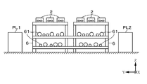
図2、図3に示すように、本例のNG液化装置1には、2系統のパイプラック6が隣り合って並列に配置されている。各パイプラック6は、上面側から見て細長い長方形の架構構造体として構成され、上述の設備群PL1、PL2を構成する機器間で授受されるNGや各種冷媒(液化用冷媒や予冷用冷媒)などの流体が流れる複数の配管61(配管61の集合体)を保持している。
前記パイプラック6の上面には、既述の液化部12に設けられている液化用冷媒サイクル121の凝縮器や過冷却器を構成するACHE2、また予冷部14が設けられている場合には、予冷用冷媒サイクル141や冷媒冷却サイクル142の減温器、凝縮器、過冷却器を構成するACHE2などが配置されている。特に、予冷用冷媒サイクル141、冷媒冷却サイクル142に設けられるACHE2は設置台数が多く、数台~数十台のACHE2を用いて凝縮器、過冷却器や凝縮器などを構成している場合もある。このため、規模によっては全体として100台近くのACHE2を備えたNG液化装置1も存在する。
図2に示すように、本例のNG液化装置1は、上面側から見て長方形のパイプラック6の上面に、前記長方形の短辺方向に沿って例えば3台のACHE2を並べて1組とし、前記長方形の長辺方向に沿って、これらACHE2の組を多数組、並べた構成となっている。
パイプラック6の上面に設けられるACHE2の一例として、図4は吸込型のACHE2の構成例を示している。
ACHE2は、被冷却流体(NG液化装置1にて取り扱われる流体:液化用冷媒や予冷用冷媒、その他、前処理部11のプロセスにて取り扱われる流体など)が流れる多数本のチューブ23を束ねたチューブバンドル230と、チューブバンドル230の上方側に配置されたファン22とを備える。
ACHE2は、被冷却流体(NG液化装置1にて取り扱われる流体:液化用冷媒や予冷用冷媒、その他、前処理部11のプロセスにて取り扱われる流体など)が流れる多数本のチューブ23を束ねたチューブバンドル230と、チューブバンドル230の上方側に配置されたファン22とを備える。
チューブバンドル230は、上下両面が開放され、隣り合うチューブ23の隙間を介して、下から上へ向かって冷却用空気を通流させることができる。またチューブバンドル230の側周部分を構成する枠体は、パイプラック6を構成する架構の上面に固定されている。
ファン22は、回転中心から放射状に伸びるように設けられた複数枚の動翼220を備える。各動翼220の基端部は、前記回転中心にて回転軸222の上端部に接続され、当該回転軸222は上下方向へ伸びるように配置されている。回転軸222の下部側はチューブバンドル230を貫通し、その下端部は、当該チューブバンドル230の下方に配置された回転駆動部221と接続されている。
例えば図4の縦断側面図に示すように、回転駆動部221は、回転軸222の下端部に設けられたファンプーリー223と、当該ファンプーリー223の側方に配置された回転モーター226の回転軸側のモータープーリー224とに駆動ベルト225を捲回し、駆動ベルト225を介して回転軸222を回転させる構成としてもよい。
また、回転軸222を回転モーターに直接、連結した構成としてもよい。
また、回転軸222を回転モーターに直接、連結した構成としてもよい。
チューブバンドル230の枠体の上面から、ファン22の側方一を通ってその上方側に至る領域には、チューブバンドル230を通過した空気を通流させる排気経路を成すダクト21が設けられている。ダクト21は、ファン22の上方側の位置にて、上面側へ向けて開口している。
上述の構成を備えたACHE2にて、ファン22を回転させると、チューブバンドル230を下方側から上方側へ通過する冷却用空気(冷却用流体)の流れが形成される。そして各チューブ23の表面に供給された冷却用空気との熱交換により、チューブ23内を流れる被冷却流体の冷却が行われる。
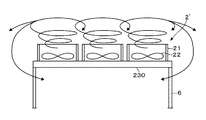
ここで、チューブバンドル230、ファン22、回転駆動部221、及びダクト21を備えた従来のACHE2’についての問題点について、図10の模式図を参照しながら説明する。
従来のACHE2’において、ファン22を回転させることにより供給されたエネルギーは、主としてチューブバンドル230の下面から冷却用空気を取り込み、多数のチューブ23の隙間を通過させて、ダクト21の上面側の開口から排出するまでの圧力差の形成(静圧分のエネルギー)、冷却用空気の流れの形成(動圧分のエネルギー)に消費される。
従来のACHE2’において、ファン22を回転させることにより供給されたエネルギーは、主としてチューブバンドル230の下面から冷却用空気を取り込み、多数のチューブ23の隙間を通過させて、ダクト21の上面側の開口から排出するまでの圧力差の形成(静圧分のエネルギー)、冷却用空気の流れの形成(動圧分のエネルギー)に消費される。
本願の発明者は、ファン22から供給されたエネルギー全体のうち、上述の静圧分のエネルギーの消費が70%程度、動圧分のエネルギーの消費が10%程度であることを把握した。従って、残る20%分のエネルギーは、ACHE2’の入口-出口間の圧力差形成(即ち、昇圧)や流れの形成に利用されていないとも言える。
さらに発明者は、ACHE2’の冷却能力に寄与せずに失われているエネルギーの消費先が、ファン22の回転に伴う旋回流の形成や、乱流散逸であることを把握した。一般にACHE2’により形成される冷却用空気の流れは乱流であることから、乱流散逸を低減することは困難である。
そこで、本願のACHE2は、旋回流の形成を抑えることにより、旋回流の形成のために失われていたエネルギーを冷却用空気の昇圧や流れの形成に変換することが可能な構成を備えている。
そこで、本願のACHE2は、旋回流の形成を抑えることにより、旋回流の形成のために失われていたエネルギーを冷却用空気の昇圧や流れの形成に変換することが可能な構成を備えている。
また、図10に模式的に示すように、ダクト21から放出された旋回流は、横方向に広がる。このため、ACHE2’から排出された比較的温度の高い空気が、当該ACHE2’の下方側や、隣接するパイプラック6に設置されたACHE2’の下方側に流れ込んでその冷却能力を低下させてしまう、HAR(Hot Air Recirculation)と呼ばれる現象を発生させるおそれもある。このようなHARの発生を抑制する観点でも、旋回流の形成を抑制することが望ましい。
以下、図4~図7を参照しながら旋回流の形成を抑えるための構成について説明する。
本例のACHE2は、ファン22によって形成された旋回流を垂直方向の流れに整流する静翼24を備えている。
本例のACHE2は、ファン22によって形成された旋回流を垂直方向の流れに整流する静翼24を備えている。
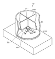
図4、図7などに示すように、静翼24は、ファン22よりも上方側の領域のダクト21内に複数枚の平板を配置して構成する場合を例示することができる。図5に示すように、これら複数枚の静翼24は、ダクト21を平面視したときの中央位置から、ダクト21の内壁面へ向けて、放射状に広がるように設けられている。
本例では、ファン22の回転軸222の上方位置に、当該回転軸222の延伸方向(垂直方向)に沿って支持軸241を配置し、当該支持軸241の外周面と、ダクト21の内周面との間を繋ぐように各静翼24が保持されている。
ここで、旋回流を十分に整流するためには、図4に示すファンの上端位置からダクトの開口までの高さHと、ダクトの開口直径Dの比であるH/Dの値が小さくなる程、多数枚の静翼24を設置しなければならない。一方で、H/Dの値が大きくなるに連れて、静翼24の設置枚数は少なくすることができる。
NG液化装置1に設けられるACHE2においては、H/Dは0.1~1.5の範囲内の値を例示することができる。このとき、静翼24の設置枚数は2~8の範囲内の枚数が好適である。
なお、パイプラック6(チューブバンドル230)への接続位置を基端位置とするダクト21の高さとしては、1~15m程度の範囲を例示することができる。
なお、パイプラック6(チューブバンドル230)への接続位置を基端位置とするダクト21の高さとしては、1~15m程度の範囲を例示することができる。
また、静翼24を設置することに伴う騒音の発生を抑制する観点からは、静翼24の設置枚数とファン22の動翼220の設置枚数とが異なっていることが好ましい。
例えば図5、図6には、ファン22に設けられている動翼220の枚数が、静翼24の設置枚数よりも多い例を示している。この場合には静翼24の設置枚数は、動翼220の枚数の約数と相違する枚数であることがさらに好ましい。
例えば図5、図6には、ファン22に設けられている動翼220の枚数が、静翼24の設置枚数よりも多い例を示している。この場合には静翼24の設置枚数は、動翼220の枚数の約数と相違する枚数であることがさらに好ましい。
図5に示すACHE2のファン22は、動翼220が6枚であるので、静翼24の設置枚数は、動翼220の枚数の約数(3、2)と相違する4枚となっている。
また、図6に示すACHE2のファン22は、動翼220が4枚であるので、静翼24の設置枚数は、動翼220の枚数の約数(2)と相違する3枚となっている。
また、図6に示すACHE2のファン22は、動翼220が4枚であるので、静翼24の設置枚数は、動翼220の枚数の約数(2)と相違する3枚となっている。
上述の構成を備えたACHE2の作用について、図8の模式図を参照しながら説明する。ファン22によって形成された旋回流は静翼24によって垂直方向の流れに整流されるので、旋回流の形成を抑えることができる。この結果、従来のACHE2’にて、発生していた旋回流の形成に伴うエネルギー損失を、ACHE2の入口-出口間の昇圧や、冷却用空気の流速に転換することができる。この結果、静翼24を設けない場合と比較して、冷却用空気の流量が増加すると共に、ダクト21の開口位置における冷却用空気の排気流速も上昇する。
HARの発生を抑える観点からは、ダクト21の開口から排出される冷却用空気の垂直方向の流速は5~20m/sの範囲内の値であることが好ましい。
従って、既述のようにH/Dの値が0.1~1.5の範囲内で、2~8枚の静翼24を設置する際に、さらに冷却用空気の垂直方向の流速が5~20m/sの範囲内の値となるように、静翼24の設置枚数を選択してもよい。静翼24の設置枚数を変化させたときのダクト21の開口における冷却用空気の流速は、CFD(Computational Fluid Dynamics、数値流体力学解析)により特定することができる。
従って、既述のようにH/Dの値が0.1~1.5の範囲内で、2~8枚の静翼24を設置する際に、さらに冷却用空気の垂直方向の流速が5~20m/sの範囲内の値となるように、静翼24の設置枚数を選択してもよい。静翼24の設置枚数を変化させたときのダクト21の開口における冷却用空気の流速は、CFD(Computational Fluid Dynamics、数値流体力学解析)により特定することができる。
静翼24は、NG液化装置1の建設時に、当該静翼24を備えたACHE2を設置する場合のみならず、既設のNG液化装置1に設けられたACHE2’を改造することによっても設置することができる。
既にダクト21を備えるACHE2’に対しては、静翼24のみを追加設置してもよい。また、ダクト21を備えない、またはダクト21の高さや強度が不足するACHE2’に対しては、ダクト21の交換、改造と共に静翼24を設置してもよい。
既にダクト21を備えるACHE2’に対しては、静翼24のみを追加設置してもよい。また、ダクト21を備えない、またはダクト21の高さや強度が不足するACHE2’に対しては、ダクト21の交換、改造と共に静翼24を設置してもよい。
NG液化装置1内に設けられている多数のACHE2のうち、全てのACHE2に静翼24を設けてもよいし、一部のACHE2にのみ静翼24を設けてもよい。
本実施の形態に係るNG液化装置1によれば以下の効果がある。NG液化装置に設けられているACHE2のファン22の上方側のダクト21内に、旋回流を垂直方向の流れに整流する支持軸241を設けているので、旋回流の発生に伴うエネルギー損失を抑え、冷却用空気の風量低下を抑制することができる。
ここで、支持軸241の構成については、図4~図7を用いて説明した例の如く、平板を用いる場合に限定されない。例えば図9に示す静翼24aのように、ファン22の回転方向に沿って、下端部側から上端部側へ向けて、水平方向に対する傾きが次第に大きくなるように湾曲した板材を設けてもよい。例えば、30~90℃(垂直)の範囲で水平方向に対する傾きを調整することができる。旋回流の流れを次第に垂直方向の流れに整流することにより、騒音や乱流散逸の増大を抑えることができる。
さらにここで、静翼24、24aが設けられたACHE2を利用する天然ガス処理装置は、図1(a)、(b)に示したNG液化装置1の例に限定されるものではない。例えばNGから、コンデンセートを含むエタンよりも重質の液体を回収し、メタンより軽質の気体については、液化を行わずにガスの状態で需要先に出荷したり、工場内で燃料ガスとして消費したりするNGL(Natural Gas Liquids)装置内に設けられるACHE2に静翼24、24aを併設してもよい。
1 NG液化装置
2、2’ ACHE
21 ダクト
22 ファン
220 動翼
221 回転駆動部
230 チューブバンドル
24、24a
静翼
241 支持軸
6 パイプラック
2、2’ ACHE
21 ダクト
22 ファン
220 動翼
221 回転駆動部
230 チューブバンドル
24、24a
静翼
241 支持軸
6 パイプラック
Claims (7)
- 天然ガスを処理する天然ガス処理装置において、
前記天然ガス液化装置にて取り扱われる流体である被冷却流体が流れるチューブを束ねたチューブバンドルと、前記チューブバンドルの上方側に設けられ、前記被冷却流体を冷却するために、前記チューブバンドルに対して冷却用空気を供給するファンと、前記チューブバンドルの上面から、前記ファンの側方位置を通って当該ファンの上方側の位置にて開口し、前記冷却用流体の排気経路を成すダクトと、が設けられた空冷式熱交換器を備え、
前記空冷式熱交換器は、前記ファンよりも上方側の前記ダクト内に設けられ、当該ファンにより形成された旋回流を垂直方向の流れに整流する静翼を備えたこと特徴とする天然ガス処理装置。 - 前記空冷式熱交換器の静翼は、前記ダクトを平面視したときの中央位置から、当該ダクトの内壁面へ向けて、放射状に広がるように複数枚設けられていることを特徴とする請求項1に記載の天然ガス処理装置。
- 前記空冷式熱交換器は、ファンの上端位置から、前記ダクトの開口までの高さHと、前記ダクトの開口直径Dとの比であるH/Dが0.1~1.5の範囲内の値であるとき、前記静翼の設置枚数が2~8の間の枚数であることを特徴とする請求項1に記載の天然ガス処理装置。
- 前記空冷式熱交換器のファンは複数枚の動翼を備え、前記動翼の枚数と、前記静翼の設置枚数とが異なることを特徴とする請求項1に記載の天然ガス処理装置。
- 前記空冷式熱交換器のファンに設けられている動翼の枚数が、前記静翼の設置枚数よりも多いとき、当該静翼の設置枚数は、前記動翼の枚数の約数と相違する枚数であることを特徴とする請求項4に記載の天然ガス処理装置。
- 前記空冷式熱交換器の静翼は、前記ファンの回転方向に沿って、下端部側から上端部側へ向けて、水平方向に対する傾きが次第に大きくなるように湾曲していることを特徴とする請求項1に記載の天然ガス処理装置。
- 前記空冷式熱交換器の静翼は、前記旋回流を整流して、前記ダクトの開口から排出される冷却用空気の垂直方向の流速が5~20m/sの範囲内の値となるように設けられていることを特徴とする請求項1に記載の天然ガス処理装置。
Priority Applications (1)
| Application Number | Priority Date | Filing Date | Title |
|---|---|---|---|
| PCT/JP2018/027992 WO2020021668A1 (ja) | 2018-07-25 | 2018-07-25 | 天然ガス処理装置 |
Applications Claiming Priority (1)
| Application Number | Priority Date | Filing Date | Title |
|---|---|---|---|
| PCT/JP2018/027992 WO2020021668A1 (ja) | 2018-07-25 | 2018-07-25 | 天然ガス処理装置 |
Publications (1)
| Publication Number | Publication Date |
|---|---|
| WO2020021668A1 true WO2020021668A1 (ja) | 2020-01-30 |
Family
ID=69181506
Family Applications (1)
| Application Number | Title | Priority Date | Filing Date |
|---|---|---|---|
| PCT/JP2018/027992 Ceased WO2020021668A1 (ja) | 2018-07-25 | 2018-07-25 | 天然ガス処理装置 |
Country Status (1)
| Country | Link |
|---|---|
| WO (1) | WO2020021668A1 (ja) |
Citations (8)
| Publication number | Priority date | Publication date | Assignee | Title |
|---|---|---|---|---|
| JPS5029629U (ja) * | 1973-07-11 | 1975-04-03 | ||
| JPS61502267A (ja) * | 1984-05-23 | 1986-10-09 | エアフロ−・リサ−チ・アンド・マニュファクチュアリング・コ−ポレ−ション | ファン及びハウジング |
| US5066194A (en) * | 1991-02-11 | 1991-11-19 | Carrier Corporation | Fan orifice structure and cover for outside enclosure of an air conditioning system |
| JP2000205194A (ja) * | 1998-12-31 | 2000-07-25 | Halla Aircon Co Ltd | 軸流ファン用案内羽及びその案内羽を備える軸流ファンシュラウド組立体 |
| JP2003294269A (ja) * | 2002-04-01 | 2003-10-15 | Takasago Thermal Eng Co Ltd | 室外機の配置システム |
| JP2006214419A (ja) * | 2005-02-07 | 2006-08-17 | Sanyo Denki Co Ltd | 軸流送風機 |
| CN102374801A (zh) * | 2010-08-23 | 2012-03-14 | 李宁 | 驭风空冷塔 |
| WO2017125965A1 (ja) * | 2016-01-21 | 2017-07-27 | 日揮株式会社 | 天然ガス処理装置 |
-
2018
- 2018-07-25 WO PCT/JP2018/027992 patent/WO2020021668A1/ja not_active Ceased
Patent Citations (8)
| Publication number | Priority date | Publication date | Assignee | Title |
|---|---|---|---|---|
| JPS5029629U (ja) * | 1973-07-11 | 1975-04-03 | ||
| JPS61502267A (ja) * | 1984-05-23 | 1986-10-09 | エアフロ−・リサ−チ・アンド・マニュファクチュアリング・コ−ポレ−ション | ファン及びハウジング |
| US5066194A (en) * | 1991-02-11 | 1991-11-19 | Carrier Corporation | Fan orifice structure and cover for outside enclosure of an air conditioning system |
| JP2000205194A (ja) * | 1998-12-31 | 2000-07-25 | Halla Aircon Co Ltd | 軸流ファン用案内羽及びその案内羽を備える軸流ファンシュラウド組立体 |
| JP2003294269A (ja) * | 2002-04-01 | 2003-10-15 | Takasago Thermal Eng Co Ltd | 室外機の配置システム |
| JP2006214419A (ja) * | 2005-02-07 | 2006-08-17 | Sanyo Denki Co Ltd | 軸流送風機 |
| CN102374801A (zh) * | 2010-08-23 | 2012-03-14 | 李宁 | 驭风空冷塔 |
| WO2017125965A1 (ja) * | 2016-01-21 | 2017-07-27 | 日揮株式会社 | 天然ガス処理装置 |
Similar Documents
| Publication | Publication Date | Title |
|---|---|---|
| CN1122807C (zh) | 液化天然气的设备 | |
| BRPI0904895A2 (pt) | sistema de liquefação de gás natural, método para liquefação de gás natural, e sistema de liquefação de gás natural para plantas de liquefação de grande capacidade | |
| JP6725571B2 (ja) | ダブルフロー圧縮器を用いたlngプラントにおける並列圧縮 | |
| BR112019017533A2 (pt) | Sistema liquidificante de gás natural, e, método. | |
| WO2016001952A1 (ja) | 空冷式液化ガス製造設備 | |
| JP6360987B1 (ja) | 天然ガス液化装置、及び天然ガス液化装置の設計方法 | |
| WO2017175384A1 (ja) | ガス処理装置 | |
| RU2747868C1 (ru) | Модуль для устройства сжижения природного газа и устройство сжижения природного газа | |
| US11162746B2 (en) | Liquid drains in core-in-shell heat exchanger | |
| US10935312B2 (en) | Balancing power in split mixed refrigerant liquefaction system | |
| RU2665015C1 (ru) | Установка для сжижения газа | |
| US11747081B2 (en) | Method and system for efficient nonsynchronous LNG production using large scale multi-shaft gas turbines | |
| US11913717B2 (en) | Natural gas liquefying apparatus | |
| JP7313459B2 (ja) | 天然ガス液化装置 | |
| WO2019159371A1 (ja) | 天然ガス液化装置 | |
| WO2017125965A1 (ja) | 天然ガス処理装置 | |
| JP2020159647A (ja) | 天然ガス液化装置 | |
| CA3150438A1 (en) | Heat exchanger system and method | |
| AU2017419936A1 (en) | Natural gas liquefaction device | |
| WO2020075295A1 (ja) | 天然ガス液化装置 | |
| BR112020005256A2 (pt) | sistema de refrigerante misto e método |
Legal Events
| Date | Code | Title | Description |
|---|---|---|---|
| 121 | Ep: the epo has been informed by wipo that ep was designated in this application |
Ref document number: 18927359 Country of ref document: EP Kind code of ref document: A1 |
|
| NENP | Non-entry into the national phase |
Ref country code: DE |
|
| 122 | Ep: pct application non-entry in european phase |
Ref document number: 18927359 Country of ref document: EP Kind code of ref document: A1 |