WO2020013088A1 - アクセスポイント及び通信方法 - Google Patents
アクセスポイント及び通信方法 Download PDFInfo
- Publication number
- WO2020013088A1 WO2020013088A1 PCT/JP2019/026753 JP2019026753W WO2020013088A1 WO 2020013088 A1 WO2020013088 A1 WO 2020013088A1 JP 2019026753 W JP2019026753 W JP 2019026753W WO 2020013088 A1 WO2020013088 A1 WO 2020013088A1
- Authority
- WO
- WIPO (PCT)
- Prior art keywords
- band
- frequency band
- channel
- terminal
- rts
- Prior art date
Links
- 238000004891 communication Methods 0.000 title claims description 371
- 238000000034 method Methods 0.000 title claims description 215
- 230000005540 biological transmission Effects 0.000 description 300
- 238000010586 diagram Methods 0.000 description 88
- 230000004044 response Effects 0.000 description 72
- 238000012545 processing Methods 0.000 description 45
- 238000012937 correction Methods 0.000 description 43
- 230000000694 effects Effects 0.000 description 17
- 238000013507 mapping Methods 0.000 description 11
- 238000001514 detection method Methods 0.000 description 10
- 239000000523 sample Substances 0.000 description 10
- 230000008569 process Effects 0.000 description 9
- 230000002123 temporal effect Effects 0.000 description 7
- 239000000969 carrier Substances 0.000 description 5
- 238000004590 computer program Methods 0.000 description 4
- 238000005516 engineering process Methods 0.000 description 4
- 239000013589 supplement Substances 0.000 description 4
- 101100172132 Mus musculus Eif3a gene Proteins 0.000 description 3
- 230000002411 adverse Effects 0.000 description 3
- 230000008054 signal transmission Effects 0.000 description 3
- 230000009471 action Effects 0.000 description 2
- 238000006243 chemical reaction Methods 0.000 description 2
- 239000000470 constituent Substances 0.000 description 2
- 230000010354 integration Effects 0.000 description 2
- 238000012986 modification Methods 0.000 description 2
- 230000004048 modification Effects 0.000 description 2
- 239000004065 semiconductor Substances 0.000 description 2
- 230000006978 adaptation Effects 0.000 description 1
- 238000001914 filtration Methods 0.000 description 1
- 230000006872 improvement Effects 0.000 description 1
- 239000000463 material Substances 0.000 description 1
- 230000002093 peripheral effect Effects 0.000 description 1
- 238000002360 preparation method Methods 0.000 description 1
- 230000001360 synchronised effect Effects 0.000 description 1
Images


Classifications
-
- H—ELECTRICITY
- H04—ELECTRIC COMMUNICATION TECHNIQUE
- H04W—WIRELESS COMMUNICATION NETWORKS
- H04W74/00—Wireless channel access
- H04W74/08—Non-scheduled access, e.g. ALOHA
- H04W74/0808—Non-scheduled access, e.g. ALOHA using carrier sensing, e.g. carrier sense multiple access [CSMA]
- H04W74/0816—Non-scheduled access, e.g. ALOHA using carrier sensing, e.g. carrier sense multiple access [CSMA] with collision avoidance
-
- H—ELECTRICITY
- H04—ELECTRIC COMMUNICATION TECHNIQUE
- H04W—WIRELESS COMMUNICATION NETWORKS
- H04W72/00—Local resource management
- H04W72/04—Wireless resource allocation
- H04W72/044—Wireless resource allocation based on the type of the allocated resource
- H04W72/0453—Resources in frequency domain, e.g. a carrier in FDMA
-
- H—ELECTRICITY
- H04—ELECTRIC COMMUNICATION TECHNIQUE
- H04W—WIRELESS COMMUNICATION NETWORKS
- H04W72/00—Local resource management
- H04W72/20—Control channels or signalling for resource management
- H04W72/23—Control channels or signalling for resource management in the downlink direction of a wireless link, i.e. towards a terminal
-
- H—ELECTRICITY
- H04—ELECTRIC COMMUNICATION TECHNIQUE
- H04W—WIRELESS COMMUNICATION NETWORKS
- H04W74/00—Wireless channel access
- H04W74/002—Transmission of channel access control information
-
- H—ELECTRICITY
- H04—ELECTRIC COMMUNICATION TECHNIQUE
- H04W—WIRELESS COMMUNICATION NETWORKS
- H04W80/00—Wireless network protocols or protocol adaptations to wireless operation
- H04W80/02—Data link layer protocols
Definitions
- the present invention relates to an access point and a communication method.
- IEEE 802.11a As a conventional wireless communication system relating to a wireless LAN (Local Area Network), there are IEEE 802.11a, IEEE 802.11ax and the like shown in Non-Patent Documents 1 and 2.
- IEEE@802.11ax is a wireless communication system having a maximum frequency band of 160 MHz in a 2.4 GHz band or a 5 GHz band.
- the modulated signals of a plurality of streams are simultaneously transmitted using the same frequency (common frequency) using a plurality of antennas, thereby improving the data reception quality and / or (per unit time).
- a communication method called MIMO (Multiple-Input @ Multiple-Out) that increases the data communication speed is applied.
- the present invention provides an access point or the like that executes a new communication method for further improving the data transmission speed.
- An access point includes a first interface that performs wireless communication in a first band, a second interface that performs wireless communication in a second band different from the first band, the first interface and the second interface.
- RTS Request to Send
- CTS Cert to Send
- a terminal and a control unit to perform, the first method of the three methods transmits a first RTS signal in the first band or the second band, and is transmitted with respect to the first RTS signal.
- the first CTS signal is received.
- the second of the three methods is the first band or the second band.
- Is a method of transmitting a second RTS signal addressed to a plurality of terminals and receiving a second CTS signal transmitted in response to the second RTS signal, and a third method of the three methods is: In this method, a third RTS signal addressed to a plurality of terminals is transmitted in each of the first band and the second band, and a third CTS signal transmitted in response to the third RTS signal is received.
- a recording medium such as a system, a method, an integrated circuit, a computer program or a computer-readable CD-ROM, and the system, the method, the integrated circuit, and the computer program. And any combination of recording media.
- one or more frequency bands can be suitably selected and used, so that the effect of improving the data transmission speed of the communication system can be obtained.
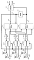
- FIG. 1 is a diagram illustrating an example of a configuration of a communication device.
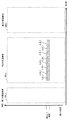
- FIG. 2 is a diagram illustrating transmission and reception of a modulated signal.
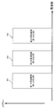
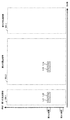
- FIG. 3A is a diagram illustrating a configuration of an RTS signal.
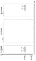
- FIG. 3B is a diagram illustrating a configuration of a signal of the MU-RTS.
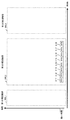
- FIG. 3C is a diagram illustrating a configuration of a signal of the MC-MU-RTS.
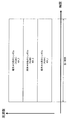
- FIG. 4A is a diagram illustrating an example of a frame configuration.
- FIG. 4B is a diagram illustrating an example of a frame configuration.
- FIG. 5A is a diagram illustrating an example of a frame configuration.
- FIG. 5B is a diagram illustrating an example of a frame configuration.
- FIG. 5A is a diagram illustrating an example of a frame configuration.
- FIG. 5B is a diagram illustrating an example of a frame configuration.
- FIG. 5C is a diagram illustrating an example of a frame configuration.
- FIG. 5D is a diagram illustrating an example of a frame configuration.
- FIG. 5E is a diagram illustrating an example of a frame configuration.
- FIG. 5F is a diagram illustrating an example of a frame configuration.
- FIG. 5G is a diagram illustrating an example of a frame configuration.
- FIG. 5H is a diagram illustrating an example of a frame configuration.
- FIG. 5I is a diagram illustrating an example of a frame configuration.
- FIG. 5J is a diagram illustrating an example of a frame configuration.
- FIG. 5K is a diagram illustrating an example of a frame configuration.
- FIG. 6A is a diagram illustrating an example of the configuration of a data symbol.
- FIG. 6A is a diagram illustrating an example of the configuration of a data symbol.
- FIG. 6A is a diagram illustrating an example of the configuration of a data symbol.
- FIG. 6A is
- FIG. 6B is a diagram illustrating an example of the configuration of a data symbol.
- FIG. 7 is a diagram illustrating an example of a frame configuration.
- FIG. 8 is a diagram illustrating an example of a frame configuration.
- FIG. 9 is a diagram illustrating an example of a frame configuration.
- FIG. 10 is a diagram illustrating an example of a frame configuration.
- FIG. 11 is a diagram illustrating an example of a frame configuration.
- FIG. 12 is a diagram illustrating an example of a frame configuration.
- FIG. 13 is a diagram illustrating an example of a frame configuration.
- FIG. 14 is a diagram illustrating an example of a frame configuration.
- FIG. 15 is a diagram illustrating an example of a frame configuration.
- FIG. 16 is a diagram illustrating an example of a frame configuration.
- FIG. 15 is a diagram illustrating an example of a frame configuration.
- FIG. 17 is a diagram illustrating an example of a frame configuration.
- FIG. 18 is a diagram illustrating an example of a frame configuration.
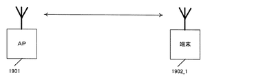
- FIG. 19A is a diagram illustrating an example of a communication state of an access point.
- FIG. 19B is a diagram illustrating an example of the communication state of the access point.
- FIG. 20A is a diagram illustrating a configuration of a transmission unit included in the transmission / reception device.
- FIG. 20B is a diagram illustrating a configuration of a receiving unit included in the transmission / reception device.
- FIG. 21A is a diagram illustrating a frequency band for transmitting a modulation signal.
- FIG. 21B is a diagram showing a frequency band for transmitting a modulation signal.
- FIG. 21A is a diagram illustrating a frequency band for transmitting a modulation signal.
- FIG. 21C is a diagram showing a frequency band for transmitting a modulation signal.
- FIG. 22A is a diagram illustrating an example of transmission of the RTS.
- FIG. 22B is a diagram illustrating an example of CTS transmission.
- FIG. 22C is a diagram illustrating an example of transmission of a symbol group.
- FIG. 23A is a diagram illustrating an example of transmission of a CTS.
- FIG. 23B is a diagram illustrating an example of transmission of a symbol group.
- FIG. 24A is a diagram illustrating an example of CTS transmission.
- FIG. 24B is a diagram illustrating an example of transmission of a symbol group.
- FIG. 25A is a diagram illustrating an example of CTS transmission.
- FIG. 25B is a diagram illustrating an example of transmission of a symbol group.
- FIG. 26A is a diagram illustrating an example of RTS transmission.
- FIG. 26B is a diagram illustrating an example of transmission of the CTS.
- FIG. 26C is a diagram illustrating an example of transmission of a symbol group.
- FIG. 27A is a diagram illustrating an example of RTS transmission.
- FIG. 27B is a diagram illustrating an example of CTS transmission.
- FIG. 27C is a diagram illustrating an example of transmission of a symbol group.
- FIG. 28A is a diagram illustrating an example of RTS transmission.
- FIG. 28B is a diagram illustrating an example of CTS transmission.
- FIG. 28C is a diagram illustrating an example of transmission of a symbol group.
- FIG. 29A is a diagram illustrating an example of RTS transmission.
- FIG. 29A is a diagram illustrating an example of RTS transmission.
- FIG. 29A is a diagram illustrating an example of RTS transmission.
- FIG. 29A is a diagram illustrating an example of RTS
- FIG. 29B is a diagram illustrating an example of CTS transmission.
- FIG. 29C is a diagram illustrating an example of CTS transmission.
- FIG. 29D is a diagram illustrating an example of transmission of a symbol group.
- FIG. 30 is a diagram illustrating an example of communication between a terminal and an access point.
- FIG. 31A is a diagram illustrating an example of transmission of the RTS.
- FIG. 31B is a diagram illustrating an example of transmission of the CTS.
- FIG. 31C is a diagram illustrating an example of transmission of a symbol group.
- FIG. 32 is a diagram illustrating an example of communication between a terminal and an access point.
- FIG. 33A is a diagram illustrating an example of transmission of the RTS.
- FIG. 33B is a diagram illustrating an example of transmission of the CTS.
- FIG. 33C is a diagram illustrating an example of transmission of the CTS.
- FIG. 33D is a diagram illustrating an example of transmission of a symbol group.
- FIG. 34 is a diagram illustrating an example of symbol transmission.
- FIG. 35 is a diagram illustrating an example of symbol transmission.
- FIG. 36 is a diagram illustrating an example of the configuration of a data frame.
- FIG. 37 is a diagram illustrating an example of a configuration of a beacon frame.
- FIG. 38 is a diagram illustrating an example of the configuration of a Probe @ request frame.
- FIG. 39 is a diagram illustrating an example of the configuration of a Probe @ response frame.
- FIG. 40 is a diagram illustrating an example of the configuration of an Association @ request frame.
- FIG. 41 is a diagram illustrating an example of the configuration of an Association @ response frame.
- FIG. 42 is a diagram showing the state of the system.
- FIG. 43 is a diagram illustrating an example of a configuration of a terminal.
- FIG. 44 is a diagram illustrating an example of the configuration of an Association @ request frame.
- FIG. 45 is a diagram illustrating an example of the configuration of an Association @ request frame.
- FIG. 46 is a diagram illustrating an example of the configuration of an Association @ response frame.
- FIG. 47 is a diagram illustrating an example of the configuration of the Association @ response frame.
- FIG. 48 is a diagram illustrating an example of a configuration of a beacon frame.
- FIG. 49 is a diagram illustrating an example of a configuration of a beacon frame.
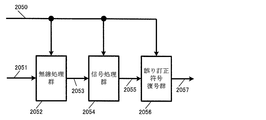
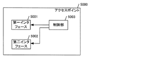
- FIG. 50 is a diagram illustrating an example of a configuration of an access point.
- FIG. 51 is a flowchart illustrating an example of a communication method executed by the access point.
- An access point includes a first interface that performs wireless communication in a first band, a second interface that performs wireless communication in a second band different from the first band, the first interface and the second interface.
- RTS Request to Send
- CTS Cert to Send
- control of one of three different systems is selected, and RTS / CTS control of the selected one system is selected.
- a control unit for performing the first RTS signal in the first band or the second band, and the first system of the three systems is transmitted with respect to the first RTS signal.
- the third of the three methods is And transmitting a third RTS signal addressed to a plurality of terminals in each of the first band and the second band, and receiving a third CTS signal transmitted in response to the third RTS signal.
- the access point can secure a communication opportunity with the terminal by one selected from the three types of RTS / CTS control. This can contribute to an improvement in the data transmission speed of communication between the access point and the terminal.
- the access point aims to improve the data transmission speed of the communication system.
- the control unit may transmit communication data using at least one of the resource units that received the CTS signal.
- the access point can use the resource unit to which the CTS signal is returned in the RTS / CTS control for communication with the terminal.
- a CTS signal may be returned in a plurality of resource units, and in that case, at least one resource unit among the plurality of resource units can be used for communication.
- the access point aims to improve the data transmission speed of the communication system.
- a source MAC (Medium Access Control) address of the third RTS signal transmitted in each of the first band and the second band may be common.
- the access point transmits the RTS signal including the common transmission source MAC address in the third scheme to the plurality of terminals in the plurality of bands. This allows the access point to more easily improve the data transmission speed of the communication system based on a more specific configuration.
- a communication method provides a communication method executed by an access point including a first interface for performing wireless communication in a first band and a second interface for performing wireless communication in a second band different from the first band.
- a method wherein at least one of the first interface and the second interface is used to select RTS (Request to Send) / CTS (Clear to Send) control of one of three different systems.
- a first CTS transmitted to the first RTS signal is transmitted to the first RTS signal.
- the second of the three systems transmits a second RTS signal addressed to a plurality of terminals in the first band or the second band, and the second RTS signal Is a method of receiving a second CTS signal transmitted to the third band.
- the third of the three systems is a third system having a plurality of terminals as destinations in each of the first band and the second band. This is a method of transmitting an RTS signal and receiving a third CTS signal transmitted in response to the third RTS signal.
- a recording medium such as a system, a method, an integrated circuit, a computer program or a computer-readable CD-ROM, and the system, the method, the integrated circuit, and the computer program.
- a recording medium such as a system, a method, an integrated circuit, a computer program or a computer-readable CD-ROM, and the system, the method, the integrated circuit, and the computer program.
- it may be realized by an arbitrary combination of recording media.
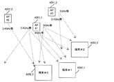
- the communication device in FIG. 1 transmits and receives a modulated signal in a first frequency band 201, for example, a 2.4 GHz band, and a modulated signal in a second frequency band 202, a 5 GHz band, as shown in FIG. It is assumed that the communication device is a communication device for performing transmission and reception of the third frequency band 203 which is a 6 (or 7) GHz band.
- antennas 104_1 and 105_1 and a transmission / reception device 102_1 are for transmitting and receiving a modulated signal in a first frequency band 201
- antennas 104_2 and 105_2 and a transmission / reception device 102_2 are used for modulation and Signals are transmitted and received
- the antennas 104_3 and 105_3 and the transmission / reception device 102_3 transmit and receive a modulated signal in the third frequency band 203.
- the communication device in FIG. 1 has a configuration of an access point (AP) device, and the AP is a communication device capable of communicating with one or more terminals. , It is possible to transmit and receive a modulated signal according to the communication method of IEEE 802.11.
- Non-Patent Document 1 a communication method related to IEEE 802.11 is described in Non-Patent Document 1, for example.
- Non-Patent Document 1 discloses a description of transmission and reception of a method of CSMA / CA (Carrier Sense Multiple Access with Collision Avoidance) in IEEE 802.11.
- CSMA / CA Carrier Sense Multiple Access with Collision Avoidance
- RTS request to to send
- CTS clear to to send
- the AP transmits an RTS signal. It is assumed that the AP can transmit the following modulated signal.
- First transmission method OFDM (Orthogonal frequency Division Multiplexing) At this time, it is assumed that a modulated signal addressed to one terminal is transmitted using the first frequency band or the second frequency band.
- Second transmission method OFDMA (Orthogonal Frequency Division Multiplexing Access)
- OFDMA Orthogonal Frequency Division Multiplexing Access
- Third transmission method One or more frequency bands of the first frequency band, the second frequency band, and the third frequency band are used, and in each frequency band, modulation for one or more terminals is performed using OFDM or OFDMA.
- a signal shall be transmitted.
- FIG. 3A shows the structure of an RTS (Request @ to @ Send) signal for the first transmission method, and the horizontal axis represents time.
- RTS Request @ to @ Send
- the RTS in FIG. 3A includes, for example, information on the address of the receiving station (communication partner) and information on the address of the transmitting station (here, the AP).
- the “address of the receiving station” is information on the address of one receiving station (communication partner).
- FIG. 3B shows the configuration of a MU-RTS (Multi-user request to to send) signal for the second transmission method, where the horizontal axis is time.
- MU-RTS Multi-user request to to send
- the MU-RTS in FIG. 3B includes, for example, information on the address of the receiving station (communication partner) and information on the address of the transmitting station (here, the AP).
- the “address of the receiving station” is information on the address of one or more receiving stations (communication partners) or information on the address of two or more receiving stations (communication partners).
- FIG. 3C shows the configuration of a signal of MC-MU-RTS (Multi-channel multi-user request to send) for the third transmission method, and the horizontal axis is time.
- MC-MU-RTS Multi-channel multi-user request to send
- the MC-MU-RTS in FIG. 3C includes, for example, information on the address of the receiving station (communication partner) and information on the address of the transmitting station (here, the AP).
- the “address of the receiving station” is information on the address of one or more receiving stations (communication partners) or information on the address of two or more receiving stations (communication partners).
- the AP transmitting / receiving apparatus 102_1 having the configuration shown in FIG. 1 transmits and receives a modulated signal in the first frequency band. Therefore, when transmitting / receiving the RTS signal, the transmitting / receiving apparatus 102_1 transmits one of the RTS in FIG. 3A, the MU-RTS in FIG. 3B, and the MC-MU-RTS in FIG. 3C.
- the transmitting / receiving apparatus 102_2 of the AP having the configuration in FIG. 1 transmits and receives the modulated signal in the second frequency band. Therefore, when transmitting / receiving the RTS signal, the transmission / reception device 102_2 transmits one of the RTS in FIG. 3A, the MU-RTS in FIG. 3B, and the MC-MU-RTS in FIG. 3C.
- the AP transmitting / receiving apparatus 102_3 having the configuration shown in FIG. 1 transmits and receives a modulated signal in the third frequency band. Therefore, when transmitting / receiving the RTS signal, the transmitting / receiving apparatus 102_3 transmits the MC-MU-RTS in FIG. 3C.
- the AP When transmitting the MC-MU-RTS of FIG. 3C, the AP transmits in one or more of the first frequency band, the second frequency band, and the third frequency band. Therefore, the following cases can be considered.
- the AP transmits the first MC-MU-RTS only in the first frequency band.
- the AP transmits the second MC-MU-RTS only in the second frequency band.
- the AP transmits the third MC-MU-RTS only in the third frequency band.
- the AP transmits a first MC-MU-RTS in a first frequency band, and transmits a second MC-MU-RTS in a second frequency band.
- the AP transmits a first MC-MU-RTS in a first frequency band and transmits a third MC-MU-RTS in a third frequency band.
- the AP transmits a second MC-MU-RTS in the second frequency band and transmits a third MC-MU-RTS in the third frequency band.
- the AP transmits a first MC-MU-RTS in a first frequency band, transmits a second MC-MU-RTS in a second frequency band, and transmits in a third frequency band.
- the third MC-MU-RTS is transmitted.
- -It is possible to communicate with one terminal only in the third frequency band.
- -It is possible to communicate with two or more terminals only in the third frequency band.
- -It is possible to communicate with one or more terminals in the third frequency band and to communicate with one or more terminals in another frequency band.
- the AP does not transmit the RTS signal of FIG. 3A and the MU-RTS signal of FIG. 3B in the third frequency band.
- Second example It is assumed that the AP can transmit the following modulated signal.
- Sixth transmission method One or more frequency bands of a first frequency band, a second frequency band, and a third frequency band are used, and in each frequency band, modulation of one or more terminals is performed using OFDM or OFDMA.
- a signal shall be transmitted.
- a modulated signal at a certain time or at a certain time zone includes a symbol of one or more terminals (one or more RUs (Resource @ Unit)).
- the frame configuration is as shown in FIGS. 4A and 4B.
- the vertical axis represents frequency (carrier), and the horizontal axis represents time.
- a symbol (RU # A) 401_1 addressed to the terminal #A exists at the first time.
- the vertical axis represents frequency (carrier), and the horizontal axis represents time.
- a symbol (RU # A) 401_1 addressed to terminal #A a symbol (RU # B) 401_2 addressed to terminal #B, and a symbol (RU # B) addressed to terminal #C ( RU # C) 401_3 is present.
- the number of frequency divisions is not limited to three.
- the frame configuration is not limited to the examples in FIGS. 4A and 4B.
- the number of frequency divisions that is, the number of destination terminals may be two or four or more. Further, the number of carriers allocated to each terminal may be different.
- frequency division is performed in FIG. 4B, but in FIG. 4B, time may be divided into three RUs by considering the vertical axis as time and the horizontal axis as frequency.
- the number of time divisions that is, the number of destination terminals may be two or more, and the number of time slots allocated to each terminal may be different.
- one or more frequency bands of the first frequency band, the second frequency band, and the third frequency band are used in a certain time zone, and one or more frequency bands are used.
- the terminal one or more RUs.
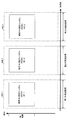
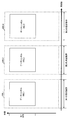
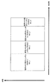
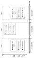
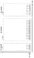
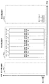
- the frame configuration is as shown in FIGS. 5A, 5B, 5C, 5D, 5E, 5F, 5G, 5H, 5I, 5J, and 5K.
- 500_1 is a frame configuration in the first frequency band
- 500_2 is a frame configuration in the second frequency band
- 500_3 is a frame configuration in the third frequency band.
- a symbol (RU # A) 501_1 destined for terminal #A exists in the first frequency band, and in the first time, the symbol (RU # A) 501_1 exists in the second frequency band.
- the symbol (RU # A) 501_2 exists in the terminal #A, and a symbol (RU # A) 501_3 destined for the terminal #A exists in the third frequency band at the first time.
- the vertical axis represents time
- the horizontal axis represents frequency (carrier).
- 5A are denoted by the same reference numerals, and description thereof will be omitted.
- a symbol (RU # A) 501_1 destined for terminal #A exists in the first frequency band, and in the first time, the symbol (RU # A) 501_1 exists in the second frequency band. And a symbol (RU # A) 501_2 addressed to the terminal #A.
- the vertical axis is time
- the horizontal axis is frequency (carrier). 5A are denoted by the same reference numerals, and description thereof will be omitted.
- a symbol (RU # A) 501_1 destined for terminal #A exists in the first frequency band, and in the first time, in the third frequency band, There is a symbol (RU # A) 501_3 addressed to terminal #A.
- FIG. 5D the vertical axis represents time, and the horizontal axis represents frequency (carrier). 5A are denoted by the same reference numerals, and description thereof will be omitted.
- a symbol (RU # A) 501_2 destined for terminal #A exists in the second frequency band, and at the first time, in the third frequency band, There is a symbol (RU # A) 501_3 addressed to terminal #A.
- the vertical axis is time, and the horizontal axis is frequency (carrier).
- 5A are denoted by the same reference numerals, and description thereof will be omitted.
- a data symbol 502_1 exists in a first frequency band
- a data symbol 502_2 exists in a second frequency band
- the data symbol 502_3 exists in the third frequency band.
- the data symbols 502_1, 502_2, and 502_3 are symbols for transmitting data, and the configuration of the data symbols 502_1, 502_2, and 502_3 will be described later with reference to FIGS. 6A and 6B.
- the vertical axis is time, and the horizontal axis is frequency (carrier).
- 5A and 5E are denoted by the same reference numerals, and description thereof is omitted.
- a data symbol 502_1 exists in a first frequency band
- a data symbol 502_2 exists in a second frequency band.
- the data symbols 502_1, 502_2, and 502_3 are symbols for transmitting data, and the configuration of the data symbols 502_1, 502_2, and 502_3 will be described later with reference to FIGS. 6A and 6B.
- the vertical axis represents time
- the horizontal axis represents frequency (carrier).
- 5A and 5E are denoted by the same reference numerals, and description thereof is omitted.
- a data symbol 502_1 exists in a first frequency band
- a data symbol 502_3 exists in a third frequency band.
- the data symbols 502_1, 502_2, and 502_3 are symbols for transmitting data, and the configuration of the data symbols 502_1, 502_2, and 502_3 will be described later with reference to FIGS. 6A and 6B.
- the vertical axis represents time
- the horizontal axis represents frequency (carrier).
- 5A and 5E are denoted by the same reference numerals, and description thereof is omitted.
- a data symbol 502_2 exists in the second frequency band
- a data symbol 502_3 exists in the third frequency band.
- the data symbols 502_1, 502_2, and 502_3 are symbols for transmitting data, and the configuration of the data symbols 502_1, 502_2, and 502_3 will be described later with reference to FIGS. 6A and 6B.
- the vertical axis is time, and the horizontal axis is frequency (carrier).
- 5A and 5E are denoted by the same reference numerals, and description thereof is omitted.
- the data symbol 502_1 exists in the first frequency band.
- the data symbols 502_1, 502_2, and 502_3 are symbols for transmitting data, and the configuration of the data symbols 502_1, 502_2, and 502_3 will be described later with reference to FIGS. 6A and 6B.
- the vertical axis represents time
- the horizontal axis represents frequency (carrier).
- 5A and 5E are denoted by the same reference numerals, and description thereof is omitted.
- the data symbols 502_1, 502_2, and 502_3 are symbols for transmitting data, and the configuration of the data symbols 502_1, 502_2, and 502_3 will be described later with reference to FIGS. 6A and 6B.
- a data symbol 502_3 exists in the third frequency band.
- the data symbols 502_1, 502_2, and 502_3 are symbols for transmitting data, and the configuration of the data symbols 502_1, 502_2, and 502_3 will be described later with reference to FIGS. 6A and 6B.
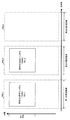
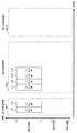
- FIG. 6A shows an example of the configuration of the data symbol 502_X in the Xth frequency band in FIGS. 5E, 5F, 5G, 5H, 5I, 5J, and 5K.
- X is 1, 2, and 3.
- the vertical axis is time, and the horizontal axis is frequency (carrier).
- data symbol 502_X is composed of symbol (RU # X1) 601_1 addressed to terminal # X1.
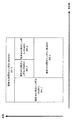
- FIG. 6B shows an example of the configuration of the data symbol 502_X in the Xth frequency band in FIGS. 5E, 5F, 5G, 5H, 5I, 5J, and 5K.
- X is 1, 2, and 3.
- the vertical axis is time, and the horizontal axis is frequency (carrier).
- data symbol 502_X includes symbol (RU # X1) 601_1 addressed to terminal # X1, symbol (RU # X2) 601_2 addressed to terminal # X2, and symbol (RU # X3) 601_3 addressed to terminal # X3.
- FIG. 6A shows an example of the configuration of the data symbol 502_X in the Xth frequency band in FIGS. 5E, 5F, 5G, 5H, 5I, 5J, and 5K.
- X is 1, 2, and 3.
- the vertical axis is time, and the horizontal axis is frequency (carrier).
- data symbol 502_X is composed of symbol (RU # X1) 601_1 addressed to terminal # X1.
- FIG. 6B shows an example of the configuration of the data symbol 502_X in the Xth frequency band in FIGS. 5E, 5F, 5G, 5H, 5I, 5J, and 5K.
- X is 1, 2, and 3.
- the vertical axis is time, and the horizontal axis is frequency (carrier).
- data symbol 502_X includes symbol (RU # X1) 601_1 addressed to terminal # X1, symbol (RU # X2) 601_2 addressed to terminal # X2, and symbol (RU # X3) 601_3 addressed to terminal # X3.
- frequency division is performed on four RUs, but the number of frequency divisions is not limited to four. Further, the configuration of data symbols 502_1, 502_2, and 502_3 is not limited to the configurations of FIGS. 6A and 6B.
- the data symbol 502_1 has one of the frame configurations shown in FIGS. 6A and 6B. 6A and 6B, and the data symbol 502_3 also adopts any of the frame configurations of FIGS. 6A and 6B.
- the data symbols 502_1, 502_2, and 502_3 may include symbols addressed to the same terminal. (For example, symbols addressed to terminal #A exist in data symbols 502_1, 502_2, and 502_3.)
- data symbols 502_1 and 502_2 may include symbols addressed to the same terminal. (For example, data symbols 502_1 and 502_2 have symbols addressed to terminal #A.)
- Data symbols 502_1 and 502_3 may include symbols addressed to the same terminal. (For example, the data symbols 502_1 and 502_3 have symbols addressed to the terminal #A.)
- Data symbols 502_2 and 502_3 may include symbols addressed to the same terminal. (For example, data symbols 502_2 and 502_3 have symbols addressed to terminal #A.)
- the APs that transmit the modulated signal by the third transmission method and the sixth transmission method include, for example, the ones shown in FIGS. 5A, 5B, 5C, 5D, 5E, 5F, 5G, 5H, 5I, and 5I. 5J and one of the frame configurations shown in FIG. 5K is selected, and the modulated signal is transmitted.
- the AP transmitting the modulated signal by the third transmission method or the sixth transmission method may be, for example, the one shown in FIGS. 5A, 5B, 5C, 5D, 5E, 5F, 5G, and 5H.
- 5I, 5J, and 5K is a selection candidate, and selects and transmits one frame configuration from the selection candidates.
- 5A, 5B, 5C, 5D, 5E, 5F, 5G, 5H, 5I, 5J, and 5K there may be symbols other than those shown in the figures.
- a preamble, a reference symbol, a control information symbol, a pilot symbol, a midamble, a null symbol (no symbol exists), a null carrier (no symbol exists), and the like may exist.
- a preamble a reference symbol, a control information symbol, a pilot symbol, a midamble, a null symbol (no symbol exists), a null carrier (no symbol exists), and the like may exist.
- FIG. 3A shows the configuration of an RTS (Request @ to @ Send) signal for the fourth transmission method, where the horizontal axis represents time.
- RTS Request @ to @ Send
- the RTS in FIG. 3A includes, for example, information on the address of the receiving station (communication partner) and information on the address of the transmitting station (here, the AP).
- the “address of the receiving station” is information on the address of one receiving station (communication partner).
- FIG. 3B shows the configuration of a MU-RTS (Multi-user request to to send) signal for the fifth transmission method, where the horizontal axis is time.
- MU-RTS Multi-user request to to send
- the MU-RTS in FIG. 3B includes, for example, information on the address of the receiving station (communication partner) and information on the address of the transmitting station (here, the AP).
- the “address of the receiving station” is information on the address of one or more receiving stations (communication partners) or information on the address of two or more receiving stations (communication partners).
- FIG. 3C shows the configuration of a signal of MC-MU-RTS (Multi-channel multi-user request to to send) for the sixth transmission method, where the horizontal axis is time.
- MC-MU-RTS Multi-channel multi-user request to to send
- the MC-MU-RTS in FIG. 3C includes, for example, information on the address of the receiving station (communication partner) and information on the address of the transmitting station (here, the AP).
- the “address of the receiving station” is information on the address of one or more receiving stations (communication partners) or information on the address of two or more receiving stations (communication partners).
- the AP transmitting / receiving apparatus 102_1 having the configuration shown in FIG. 1 transmits and receives a modulated signal in the first frequency band. Therefore, when transmitting / receiving the RTS signal, the transmitting / receiving apparatus 102_1 transmits one of the RTS in FIG. 3A, the MU-RTS in FIG. 3B, and the MC-MU-RTS in FIG. 3C.
- the transmitting / receiving apparatus 102_2 of the AP having the configuration in FIG. 1 transmits and receives the modulated signal in the second frequency band. Therefore, when transmitting / receiving the RTS signal, the transmission / reception device 102_2 transmits one of the RTS in FIG. 3A, the MU-RTS in FIG. 3B, and the MC-MU-RTS in FIG. 3C.
- the AP transmitting / receiving apparatus 102_3 having the configuration shown in FIG. 1 transmits and receives a modulated signal in the third frequency band. Therefore, when transmitting / receiving the RTS signal, the transmitting / receiving apparatus 102_3 transmits either the MU-RTS in FIG. 3B or the MC-MU-RTS in FIG. 3C.
- the AP When transmitting the MC-MU-RTS of FIG. 3C, the AP transmits in one or more of the first frequency band, the second frequency band, and the third frequency band. Therefore, the following cases can be considered.
- the AP transmits the first MC-MU-RTS only in the first frequency band.
- the AP transmits the second MC-MU-RTS only in the second frequency band.
- the AP transmits the third MC-MU-RTS only in the third frequency band.
- the AP transmits a first MC-MU-RTS in a first frequency band, and transmits a second MC-MU-RTS in a second frequency band.
- the AP transmits a first MC-MU-RTS in a first frequency band and transmits a third MC-MU-RTS in a third frequency band.
- the AP transmits a second MC-MU-RTS in the second frequency band and transmits a third MC-MU-RTS in the third frequency band.
- the AP transmits a first MC-MU-RTS in a first frequency band, transmits a second MC-MU-RTS in a second frequency band, and transmits in a third frequency band.
- the third MC-MU-RTS is transmitted.
- -It is possible to communicate with one terminal only in the third frequency band.
- -It is possible to communicate with two or more terminals only in the third frequency band.
- -It is possible to communicate with one or more terminals in the third frequency band and to communicate with one or more terminals in another frequency band.
- the AP does not transmit the RTS signal of FIG. 3A in the third frequency band.
- Case X When the A-th frequency band is the 2.4 GHz band and the B-th frequency band is 5 GHz, the A-th frequency band is considered to be the first frequency band described above, and the B-th frequency band is described above. This is considered the second frequency band, and the description up to this point is performed.
- Case Y When the A-th frequency band is the 2.4 GHz band and the B-th frequency band is 6 GHz, the A-th frequency band is considered to be the first frequency band described above, and the B-th frequency band is described above. This is considered the third frequency band, and the description so far will be made.
- Case Z If the A-th frequency band is a 5 GHz band and the B-th frequency band is 6 GHz, the A-th frequency band is considered as the second frequency band described so far, and the B-th frequency band is the second frequency band in the above description. Considering the frequency band No. 3, the description so far will be made.
- frequency bands there are four or more frequency bands as frequency bands, and the first or second frequency band or the third frequency band described so far is included in the four or more frequency bands. If it exists, it can be implemented in the same manner as described above.
- the terminal that has received each RTS transmitted by the AP transmits a CTS signal to the AP when the address of the terminal itself is included in the RTS.
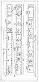
- an AP having the configuration shown in FIG. 1 transmits a modulated signal having any one of the frame configurations shown in FIGS. 7, 8, 9, 10, 10, 11, 12, and 13.
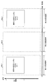
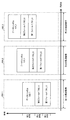
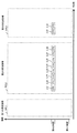
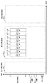
- FIG. 7 shows an example of a frame configuration of a modulated signal transmitted by the AP.
- components that operate in the same manner as in FIG. 7 are shown in FIG. 7 in FIG. 7, components that operate in the same manner as in FIG.
- the vertical axis represents time
- the horizontal axis represents frequency (carrier).
- 500_1 is a frame configuration in the first frequency band
- 500_2 is a frame configuration in the second frequency band
- 500_3 is a frame configuration in the third frequency band.
- the first field 701_1 exists in the first frequency band. Then, at the first time, the first field 701_2 exists in the second frequency band. At the first time, a first field 701_3 exists in the third frequency band.
- first fields 701_1, 701_2, and 701_3 include, for example, symbols for the communication partner of the AP to perform signal detection, time synchronization, frequency synchronization, channel estimation, and the like.
- the second field 702_1 exists in the first frequency band. Then, in the second time, the second field 702_2 exists in the second frequency band. At the second time, a second field 702_3 exists in the third frequency band.
- the second field 701_1 is a field for transmitting control information to a communication partner of the AP, and includes, for example, information on an error correction code scheme for generating a symbol (RU # A) 501_1 addressed to the terminal #A. , Modulation scheme information, transmission method information, and the like.
- the second field 701_2 is a field for transmitting control information to a communication partner of the AP. For example, information on an error correction code scheme for generating a symbol (RU # A) 501_2 addressed to the terminal #A , Modulation scheme information, transmission method information, and the like.
- a second field 701_3 is a field for transmitting control information to a communication partner of the AP, and includes, for example, information on an error correction code scheme for generating a symbol (RU # A) 501_3 addressed to the terminal #A. , Modulation scheme information, transmission method information, and the like.
- a feature is that, at a certain time, data symbols addressed to the same terminal exist in the first frequency band, the second frequency band and the third frequency band. At this time, it is assumed that there is no data symbol addressed to another terminal.
- the temporal transmission timing of the first fields 701_1, 701_2, 701_3, and the second fields 702_1, 702_2, 702_3 is not limited to the example of FIG.
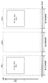
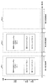
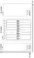
- FIG. 8 shows an example of a frame configuration of a modulated signal transmitted by the AP. 8, the same operations as those in FIGS. 5 and 7 are denoted by the same reference numerals, and description thereof will be omitted.
- the vertical axis represents time
- the horizontal axis represents frequency (carrier).
- 500_1 is a frame configuration in the first frequency band
- 500_2 is a frame configuration in the second frequency band
- 500_3 is a frame configuration in the third frequency band.
- the first field 701_1 exists in the first frequency band. Then, at the first time, the first field 701_2 exists in the second frequency band.
- first fields 701_1 and 701_2 include, for example, symbols for the communication partner of the AP to perform signal detection, time synchronization, frequency synchronization, channel estimation, and the like.
- the second field 702_1 exists in the first frequency band. Then, in the second time, the second field 702_2 exists in the second frequency band.
- the second field 701_1 is a field for transmitting control information to a communication partner of the AP, and includes, for example, information on an error correction code scheme for generating a symbol (RU # A) 501_1 addressed to the terminal #A. , Modulation scheme information, transmission method information, and the like.
- the second field 701_2 is a field for transmitting control information to a communication partner of the AP. For example, information on an error correction code scheme for generating a symbol (RU # A) 501_2 addressed to the terminal #A , Modulation scheme information, transmission method information, and the like.
- a feature is that at a certain time, data symbols addressed to the same terminal exist in the first frequency band and the second frequency band. At this time, it is assumed that there is no data symbol addressed to another terminal.
- the temporal transmission timing of the first fields 701_1, 701_2 and the second fields 702_1, 702_2 is not limited to the example in FIG.
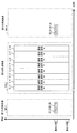
- the vertical axis represents time
- the horizontal axis represents frequency (carrier).
- 500_1 is a frame configuration in the first frequency band
- 500_2 is a frame configuration in the second frequency band
- 500_3 is a frame configuration in the third frequency band.
- the first field 701_1 exists in the first frequency band. Then, in the first time, the first field 701_3 exists in the third frequency band.
- the first fields 701_1 and 701_3 include, for example, symbols for a communication partner of the AP to perform signal detection, time synchronization, frequency synchronization, channel estimation, and the like.
- the second field 702_1 exists in the first frequency band. Then, at the second time, the second field 702_3 exists in the third frequency band.
- the second field 701_1 is a field for transmitting control information to a communication partner of the AP, and includes, for example, information on an error correction code scheme for generating a symbol (RU # A) 501_1 addressed to the terminal #A. , Modulation scheme information, transmission method information, and the like.
- the second field 701_3 is a field for transmitting control information to a communication partner of the AP, for example, information of an error correction code scheme for generating a symbol (RU # A) 501_3 addressed to the terminal #A. , Modulation scheme information, transmission method information, and the like.
- a symbol (RU # A) 501_1 destined for the terminal #A exists in the first frequency band
- a symbol (RU # A) destined for the terminal #A exists in the third frequency band.
- RU # A) 501_3 is present.
- a feature is that data symbols addressed to the same terminal exist in the first frequency band and the third frequency band at a certain time. At this time, it is assumed that there is no data symbol addressed to another terminal.
- the temporal transmission timings of the first fields 701_1 and 701_3 and the second fields 702_1 and 702_3 are not limited to the example in FIG.
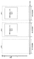
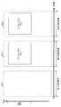
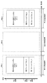
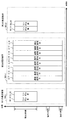
- FIG. 10 shows an example of a frame configuration of a modulated signal transmitted by the AP.
- the same operations as those in FIGS. 5 and 7 are denoted by the same reference numerals, and description thereof will be omitted.
- the vertical axis represents time
- the horizontal axis represents frequency (carrier).
- 500_1 is a frame configuration in the first frequency band
- 500_2 is a frame configuration in the second frequency band
- 500_3 is a frame configuration in the third frequency band.
- the first field 701_2 exists in the second frequency band.
- a first field 701_3 exists in the third frequency band.
- first fields 701_2 and 701_3 include, for example, symbols for a communication partner of the AP to perform signal detection, time synchronization, frequency synchronization, channel estimation, and the like.
- the second field 702_2 exists in the second frequency band.
- a second field 702_3 exists in the third frequency band.
- the second field 701_2 is a field for transmitting control information to a communication partner of the AP, and includes, for example, information on an error correction code scheme for generating a symbol (RU # A) 501_2 addressed to the terminal #A. , Modulation scheme information, transmission method information, and the like.
- a second field 701_3 is a field for transmitting control information to a communication partner of the AP, and includes, for example, information on an error correction code scheme for generating a symbol (RU # A) 501_3 addressed to the terminal #A. , Modulation scheme information, transmission method information, and the like.
- a symbol (RU # A) 501_2 destined for the terminal #A exists in the second frequency band, and at the third time, a symbol (RU # A) destined for the terminal #A in the third frequency band.
- RU # A) 501_3 is present.
- a feature is that at a certain time, data symbols addressed to the same terminal exist in the second frequency band and the third frequency band. At this time, it is assumed that there is no data symbol addressed to another terminal.
- the temporal transmission timing of the first fields 701_2 and 701_3 and the second fields 702_2 and 702_3 is not limited to the example in FIG.
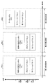
- FIG. 11 shows an example of a frame configuration of a modulated signal transmitted by the AP. 11, the same operations as those in FIGS. 5 and 7 are denoted by the same reference numerals, and description thereof will be omitted.
- the vertical axis represents time
- the horizontal axis represents frequency (carrier).
- 500_1 is a frame configuration in the first frequency band
- 500_2 is a frame configuration in the second frequency band
- 500_3 is a frame configuration in the third frequency band.
- the first field 701_1 exists in the first frequency band. Then, at the first time, the first field 701_2 exists in the second frequency band.
- first fields 701_1 and 701_2 include, for example, symbols for the communication partner of the AP to perform signal detection, time synchronization, frequency synchronization, channel estimation, and the like.
- the second field 702_1 exists in the first frequency band. Then, in the second time, the second field 702_2 exists in the second frequency band.
- the second field 701_1 is a field for transmitting control information to a communication partner of the AP, and includes, for example, information of an error correction code scheme for generating a symbol (RU # A) 501_1 addressed to the terminal #A. , Modulation scheme information, transmission method information, and the like.
- the second field 701_2 is a field for transmitting control information to the communication partner of the AP, for example, information of an error correction code scheme for generating a symbol (RU # A) 501_2 addressed to the terminal #A. , Modulation scheme information, transmission method information, and the like.
- a modulated signal exists at a timing irrelevant to the modulated signal of the first frequency band and the modulated signal of the second frequency band.
- 6A and 6B can be considered as the configuration of the data symbol 502_3.
- FIG. 6A shows an example of the configuration of data symbol 502_X in the Xth frequency band.
- X is 3.
- the vertical axis is time, and the horizontal axis is frequency (carrier).
- data symbol 502_X is composed of symbol (RU # X1) 601_1 addressed to terminal # X1.
- the symbol (RU # X1) 601_1 addressed to the terminal # X1 is not a symbol (RU # A) addressed to the terminal #A.
- the symbol (RU # X1) 601_1 addressed to the terminal # X1 may be a symbol (RU # A) addressed to the terminal #A.)
- FIG. 6B shows an example of the configuration of data symbol 502_X in the X-th frequency band.
- X is 3.
- the vertical axis is time, and the horizontal axis is frequency (carrier).
- data symbol 502_X includes symbol (RU # X1) 601_1 addressed to terminal # X1, symbol (RU # X2) 601_2 addressed to terminal # X2, and symbol (RU # X3) 601_3 addressed to terminal # X3.
- data symbol 502_X does not include a symbol (RU # A) addressed to terminal #A.
- the data symbol 502_X may include a symbol (RU # A) addressed to the terminal #A.
- frequency division is performed on four RUs, but the number of frequency divisions is not limited to four.
- the number of frequency divisions that is, the number of destination terminals may be two or more. Further, the number of carriers allocated to each terminal may be different. Further, the configuration of data symbol 502_3 is not limited to the configurations in FIGS. 6A and 6B.
- frequency division is performed, but in FIG. 6B, the vertical axis may be considered as time and the horizontal axis as frequency, and time division may be performed on four RUs.
- the number of time divisions that is, the number of destination terminals may be two or more, and the number of time slots allocated to each terminal may be different.
- data symbol 502_3 has one of the frame configurations shown in FIGS. 6A and 6B.
- a feature may be that a data symbol addressed to the same terminal exists in the first frequency band and the second frequency band at a certain time.
- FIG. 12 shows an example of a frame configuration of a modulated signal transmitted by the AP. 12, the same operations as those in FIGS. 5 and 7 are denoted by the same reference numerals, and description thereof will be omitted.
- the vertical axis represents time
- the horizontal axis represents frequency (carrier).
- 500_1 is a frame configuration in the first frequency band
- 500_2 is a frame configuration in the second frequency band
- 500_3 is a frame configuration in the third frequency band.
- the first field 701_1 exists in the first frequency band. Then, in the first time, the first field 701_3 exists in the third frequency band.
- the first fields 701_1 and 701_3 include, for example, symbols for a communication partner of the AP to perform signal detection, time synchronization, frequency synchronization, channel estimation, and the like.
- the second field 702_1 exists in the first frequency band. Then, at the second time, the second field 702_3 exists in the third frequency band.
- the second field 701_1 is a field for transmitting control information to a communication partner of the AP, and includes, for example, information of an error correction code scheme for generating a symbol (RU # A) 501_1 addressed to the terminal #A. , Modulation scheme information, transmission method information, and the like.
- the second field 701_3 is a field for transmitting control information to a communication partner of the AP, and includes, for example, information of an error correction code scheme for generating a symbol (RU # A) 501_3 addressed to the terminal #A. , Modulation scheme information, transmission method information, and the like.
- a modulated signal exists at a timing irrelevant to the modulated signal of the first frequency band and the modulated signal of the third frequency band.
- a first field 701_2 there are a first field 701_2, a second field 702_2, and a data symbol 502_2.
- 6A and 6B can be considered as the configuration of the data symbol 502_2.
- FIG. 6A shows an example of the configuration of data symbol 502_X in the Xth frequency band.
- X is 2.
- the vertical axis is time, and the horizontal axis is frequency (carrier).
- data symbol 502_X is composed of symbol (RU # X1) 601_1 addressed to terminal # X1.
- the symbol (RU # X1) 601_1 addressed to the terminal # X1 is not a symbol (RU # A) addressed to the terminal #A.
- the symbol (RU # X1) 601_1 addressed to the terminal # X1 may be a symbol (RU # A) addressed to the terminal #A.)
- FIG. 6B shows an example of the configuration of data symbol 502_X in the X-th frequency band.
- X is 2.
- the vertical axis is time, and the horizontal axis is frequency (carrier).
- data symbol 502_X includes symbol (RU # X1) 601_1 addressed to terminal # X1, symbol (RU # X2) 601_2 addressed to terminal # X2, and symbol (RU # X3) 601_3 addressed to terminal # X3.
- data symbol 502_X does not include a symbol (RU # A) addressed to terminal #A.
- the data symbol 502_X may include a symbol (RU # A) addressed to the terminal #A.
- frequency division is performed on four RUs, but the number of frequency divisions is not limited to four.
- the number of frequency divisions that is, the number of destination terminals may be two or more. Further, the number of carriers allocated to each terminal may be different. Further, the configuration of data symbol 502_2 is not limited to the configurations of FIGS. 6A and 6B.
- frequency division is performed, but in FIG. 6B, the vertical axis may be considered as time and the horizontal axis as frequency, and time division may be performed on four RUs.
- the number of time divisions that is, the number of destination terminals may be two or more, and the number of time slots allocated to each terminal may be different.
- data symbol 502_3 has one of the frame configurations shown in FIGS. 6A and 6B.
- first and third frequency bands As in the example of FIG. 12, at a certain time, data symbols addressed to the same terminal exist in the first and third frequency bands, and only data symbols addressed to other terminals exist in the second frequency band.
- the feature is that it exists.
- the temporal transmission timing of the first fields 701_1, 701_2, 701_3 and the second fields 702_1, 702_2, 702_3 is not limited to the example in FIG.
- a feature may be that a data symbol addressed to the same terminal exists in the first frequency band and the second frequency band at a certain time.
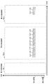
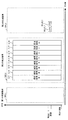
- FIG. 13 shows an example of a frame configuration of a modulated signal transmitted by the AP.
- components that operate in the same manner as in FIGS. 5 and 7 are given the same reference numerals, and descriptions thereof will be omitted.
- the vertical axis represents time
- the horizontal axis represents frequency (carrier).
- 500_1 is a frame configuration in the first frequency band
- 500_2 is a frame configuration in the second frequency band
- 500_3 is a frame configuration in the third frequency band.
- the first field 701_2 exists in the second frequency band. Then, in the first time, the first field 701_3 exists in the third frequency band.
- first fields 701_2 and 701_3 include, for example, symbols for a communication partner of the AP to perform signal detection, time synchronization, frequency synchronization, channel estimation, and the like.
- the second field 702_2 exists in the second frequency band. Then, at the second time, the second field 702_3 exists in the third frequency band.
- the second field 701_2 is a field for transmitting control information to a communication partner of the AP, and includes, for example, information of an error correction code scheme for generating a symbol (RU # A) 501_2 addressed to the terminal #A. , Modulation scheme information, transmission method information, and the like.
- the second field 701_3 is a field for transmitting control information to a communication partner of the AP, and includes, for example, information of an error correction code scheme for generating a symbol (RU # A) 501_3 addressed to the terminal #A. , Modulation scheme information, transmission method information, and the like.
- the first frequency band there is a modulated signal at a timing irrelevant to the modulated signal of the second frequency band and the modulated signal of the third frequency band.
- a modulated signal at a timing irrelevant to the modulated signal of the second frequency band and the modulated signal of the third frequency band.
- 6A and 6B can be considered as the configuration of the data symbol 502_1.
- FIG. 6A shows an example of the configuration of data symbol 502_X in the Xth frequency band.
- X becomes 1.
- the vertical axis is time, and the horizontal axis is frequency (carrier).
- data symbol 502_X is composed of symbol (RU # X1) 601_1 addressed to terminal # X1.
- the symbol (RU # X1) 601_1 addressed to the terminal # X1 is not a symbol (RU # A) addressed to the terminal #A.
- the symbol (RU # X1) 601_1 addressed to the terminal # X1 may be a symbol (RU # A) addressed to the terminal #A.)
- FIG. 6B shows an example of the configuration of data symbol 502_X in the X-th frequency band.
- X becomes 1.
- the vertical axis is time, and the horizontal axis is frequency (carrier).
- data symbol 502_X includes symbol (RU # X1) 601_1 addressed to terminal # X1, symbol (RU # X2) 601_2 addressed to terminal # X2, and symbol (RU # X3) 601_3 addressed to terminal # X3.
- data symbol 502_X does not include a symbol (RU # A) addressed to terminal #A.
- the data symbol 502_X may include a symbol (RU # A) addressed to the terminal #A.
- frequency division is performed on four RUs, but the number of frequency divisions is not limited to four.
- the number of frequency divisions that is, the number of destination terminals may be two or more. Further, the number of carriers allocated to each terminal may be different. Further, the configuration of data symbol 502_1 is not limited to the configurations of FIGS. 6A and 6B.
- frequency division is performed, but in FIG. 6B, the vertical axis may be considered as time and the horizontal axis as frequency, and time division may be performed on four RUs.
- the number of time divisions that is, the number of destination terminals may be two or more, and the number of time slots allocated to each terminal may be different.
- data symbol 502_3 has one of the frame configurations shown in FIGS. 6A and 6B.
- first fields 701_1, 701_2, 701_3 and the second fields 702_1, 702_2, 702_3 is not limited to the example of FIG.
- a feature may be that a data symbol addressed to the same terminal exists in the first frequency band and the second frequency band at a certain time.
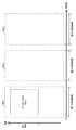
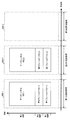
- FIG. 14 shows an example of a frame configuration of a modulated signal transmitted by the AP. 14, the same operations as those in FIGS. 5 and 7 are denoted by the same reference numerals, and description thereof will be omitted.
- the vertical axis is time, and the horizontal axis is frequency (carrier).
- 500_1 is a frame configuration in the first frequency band
- 500_2 is a frame configuration in the second frequency band
- 500_3 is a frame configuration in the third frequency band.
- the first field 701_1 exists in the first frequency band.
- the first field 701_1 includes, for example, a symbol for a communication partner of the AP to perform signal detection, time synchronization, frequency synchronization, channel estimation, and the like.
- the second field 702_1 exists in the first frequency band.
- the second field 701_1 is a field for transmitting control information to a communication partner of the AP, and includes, for example, information on an error correction code for generating a data symbol 502_1, information on a modulation scheme, and information on a transmission method. It shall contain information and the like.
- the data symbol 502_1 exists in the first frequency band.
- ⁇ ⁇ As shown in FIG. 14, in the second frequency band, there is a modulated signal at a timing unrelated to the modulated signal in the first frequency band. Also, in the third frequency band, a modulated signal exists at a timing unrelated to the modulated signal in the first frequency band. Also, in the third frequency band, a modulated signal exists at a timing irrelevant to the modulated signal in the second frequency band.
- 6A and 6B can be considered as the configuration of the data symbols 502_1, 502_2, and 502_3.
- the data symbol 502_1 has the structure of FIG. 6A or the structure of FIG. 6B.
- the data symbol 502_2 has the configuration of FIG. 6A or the configuration of FIG. 6B.
- the data symbol 502_3 has the structure of FIG. 6A or the structure of FIG. 6B.
- FIG. 6A shows an example of the configuration of data symbol 502_X in the Xth frequency band.
- X is 1, 2, and 3.
- the vertical axis is time, and the horizontal axis is frequency (carrier).
- data symbol 502_X is composed of symbol (RU # X1) 601_1 addressed to terminal # X1.
- FIG. 6B shows an example of the configuration of data symbol 502_X in the X-th frequency band.
- X is 1, 2, and 3.
- the vertical axis is time, and the horizontal axis is frequency (carrier).
- data symbol 502_X includes symbol (RU # X1) 601_1 addressed to terminal # X1, symbol (RU # X2) 601_2 addressed to terminal # X2, and symbol (RU # X3) 601_3 addressed to terminal # X3.
- frequency division is performed on four RUs, but the number of frequency divisions is not limited to four.
- the number of frequency divisions that is, the number of destination terminals may be two or more. Further, the number of carriers allocated to each terminal may be different.
- frequency division is performed, but in FIG. 6B, the vertical axis may be considered as time and the horizontal axis as frequency, and time division may be performed on four RUs.
- the number of time divisions that is, the number of destination terminals may be two or more, and the number of time slots allocated to each terminal may be different.
- a symbol (RU) addressed to the same terminal does not exist in both the data symbol 502_1 and the data symbol 502_2, and a symbol (RU) addressed to the same terminal does not exist in both the data symbol 502_1 and the data symbol 502_3; There is no symbol (RU) addressed to the same terminal in both symbol 502_2 and data symbol 502_3.
- symbols other than those shown in the figures may exist.
- a preamble, a reference symbol, a control information symbol, a pilot symbol, a midamble, a null symbol (no symbol exists), a null carrier (no symbol exists), and the like may exist.
- 6A and 6B there may be symbols other than those illustrated.
- a preamble, a reference symbol, a control information symbol, a pilot symbol, a midamble, a null symbol (no symbol exists), a null carrier (no symbol exists), and the like may exist.
- the AP transmitting the modulated signal by the third transmission method or the sixth transmission method may be, for example, any one of the frames shown in FIGS. 7, 8, 9, 10, 11, 11, 12, and 13. Select the configuration and transmit the modulated signal.
- the AP that transmits the modulated signal by the third transmission method and the sixth transmission method may be, for example, the ones shown in FIGS. 7, 8, 9, 10, 11, 12, 13, and 14. , Two or more frame configurations are selection candidates, and one frame configuration is selected from the selection candidates and transmitted.
- the AP that transmits the modulated signals of the third transmission method and the sixth transmission method has the following features.
- the data symbol 502_1 exists in the first frequency band
- the data symbol 502_2 exists in the second frequency band
- the data symbol 502_3 exists in the third frequency band.
- none of the data symbol 502_1, the data symbol 502_2, and the data symbol 502_3 have the configuration shown in FIG. 6B.
- FIG. 16 when the data symbol 502_1 exists in the first frequency band and the data symbol 502_2 exists in the second frequency band at the third time, both the data symbol 502_1 and the data symbol 502_2 are displayed. 6B is not obtained.
- FIG. 16 is not obtained.
- the data symbol 502_1 has a configuration as shown in FIG. 6B. Then, for example, consider a case where the number of symbols (RU # X1) 601_1 destined for terminal # X1 is temporally the largest. At this time, in another RU, a time period in which no symbol exists exists while the symbol of the symbol (RU # X1) 601_1 addressed to the terminal # X1 exists. Also, in the data symbol 502_2 of the second frequency band and the data symbol 502_3 of the third frequency band, while the symbol of the symbol (RU # X1) 601_1 destined for the terminal # X1 exists, the time during which no symbol exists There will be a target section.
- the AP transmits the modulated signals of the third transmission method and the sixth transmission method having the above-described features, the above-described adverse effects can be reduced, and the data transmission speed is improved. Will be.
- Case X When the A-th frequency band is the 2.4 GHz band and the B-th frequency band is 5 GHz, the A-th frequency band is considered to be the first frequency band described above, and the B-th frequency band is described above. This is considered the second frequency band, and the description up to this point is performed.
- Case Y When the A-th frequency band is the 2.4 GHz band and the B-th frequency band is 6 GHz, the A-th frequency band is considered to be the first frequency band described above, and the B-th frequency band is described above. This is considered the third frequency band, and the description so far will be made.
- Case Z If the A-th frequency band is a 5 GHz band and the B-th frequency band is 6 GHz, the A-th frequency band is considered as the second frequency band described so far, and the B-th frequency band is the second frequency band in the above description. Considering the frequency band No. 3, the description so far will be made.
- frequency bands there are four or more frequency bands as frequency bands, and the first or second frequency band or the third frequency band described so far is included in the four or more frequency bands. If it exists, it can be implemented in the same manner as described above.
- the AP transmits the modulated signal described in the present embodiment, and the terminal receiving the modulated signal obtains data by performing processing such as demodulation of the received modulated signal and decoding of an error correction code.
- processing such as demodulation of the received modulated signal and decoding of an error correction code.
- the configuration of the access point is not limited to that shown in FIG. 1 as an example.
- one or more or a plurality of transmission antennas are provided, and in each frequency band, one or more or a plurality of transmission antennas are provided.
- Any access point that generates and transmits a modulated signal can implement the present disclosure.
- each embodiment is merely an example, and illustrates, for example, “modulation method, error correction coding method (error correction code to be used, code length, coding rate, etc.), control information, and the like”. Also, the same configuration can be implemented when another “modulation scheme, error correction coding scheme (error correction code to be used, code length, coding rate, etc.), control information, etc.” is applied.
- APSK for example, 16APSK, $ 64APSK, $ 128APSK, $ 256APSK, $ 1024APSK, $ 4096APSK, etc.
- PAM for example, 4PAM, $ 8PAM, $ 16PAM, $ 64PAM, $ 128PAM, $ 256PAM, $ 1024PAM, $ 4096PAM, etc.
- PSK for example, BPSK, QPSK, QPSK 8PSK, 16PSK, 64PSK, 128PSK, 256PSK, 1024PSK, 4096PSK, etc.
- QAM eg, 4QAM, 8QAM, 16QAM, 64QAM, 128QAM, 256QAM, 1024QAM, 4096QAM, etc.
- the modulation scheme having 64, 128, 256, 1024 signal points, etc.) is not limited to the signal point arrangement method of the modulation scheme described in this specification.
- a broadcasting device for example, a broadcasting device, a base station, an access point, a terminal, a communication / broadcasting device such as a mobile phone (mobile @ phone), a television, and a radio are provided with a transmitting device, a receiving device, and a communication device. And communication devices such as personal computers. Further, the transmitting device and the receiving device according to the present disclosure are devices having a communication function, and the device provides some interface to a device for executing an application such as a television, a radio, a personal computer, and a mobile phone. It is also conceivable that it is a form that can be connected by unraveling.
- pilot symbols preamble, unique word, postamble, reference symbol, midamble, etc.
- control information symbols null symbols, and the like
- null symbols null symbols, and the like
- the pilot symbol may be, for example, a known symbol modulated using PSK modulation in a transceiver, and the receiver uses this symbol to perform frequency synchronization, time synchronization, and channel estimation (CSI (CSI) Channel ⁇ State ⁇ Information) estimation, signal detection, etc.
- the pilot symbols may be synchronized by the receiver so that the receiver can know the symbols transmitted by the transmitter.
- control information symbol is information that needs to be transmitted to a communication partner in order to realize communication other than data (data of an application or the like) (for example, a modulation scheme used for communication, an error correction coding scheme). , A coding rate of an error correction coding scheme, setting information in an upper layer, etc.).
- the present disclosure is not limited to each embodiment, and can be implemented with various modifications.
- the case where the communication method is performed as a communication device is described.
- the present invention is not limited to this, and the communication method can be performed as software.
- a program for executing the above communication method may be stored in the ROM in advance, and the program may be operated by the CPU.
- a program for executing the communication method may be stored in a computer-readable storage medium, the program stored in the storage medium may be recorded in a RAM of the computer, and the computer may be operated according to the program. .
- Each configuration of the above-described embodiments and the like may be typically realized as an LSI which is an integrated circuit having an input terminal and an output terminal. These may be individually formed into one chip, or may be formed into one chip so as to include all or a part of the configuration of each embodiment.
- the name used here is LSI, but it may also be called IC, system LSI, super LSI, or ultra LSI depending on the degree of integration.
- the method of circuit integration is not limited to LSI, and may be realized by a dedicated circuit or a general-purpose processor. After the LSI is manufactured, a programmable FPGA or a reconfigurable processor capable of reconfiguring connection and setting of circuit cells inside the LSI may be used.
- an integrated circuit technology that replaces the LSI appears due to the progress of the semiconductor technology or another derivative technology, the functional blocks may be naturally integrated using the technology. Adaptation of biotechnology is possible.
- the transmission method supported by the base station and the terminal may be a multicarrier method such as OFDM or a single carrier method. Further, the base station may support both the multi-carrier scheme and the single-carrier scheme. At this time, there are a plurality of methods for generating a single-carrier modulation signal, and any of these methods can be used.
- DFT Discrete Fourier Transform
- SC Single Carrier
- SC Single Carrier
- At least one of an FPGA (Field Programmable Gate Array) and a CPU (Central Processing Unit) can download all or a part of software necessary for realizing the communication method described in the present disclosure by wireless communication or wired communication.
- an FPGA Field Programmable Gate Array
- a CPU Central Processing Unit
- the configuration may be such that all or a part of the software for updating can be downloaded by wireless communication or wired communication.
- the downloaded software may be stored in the storage unit, and the digital signal processing described in the present disclosure may be executed by operating at least one of the FPGA and the CPU based on the stored software.
- the device including at least one of the FPGA and the CPU may be connected to the communication modem wirelessly or by wire, and the communication method described in the present disclosure may be realized by the device and the communication modem.
- a communication device such as a base station, an AP, or a terminal described in this specification includes at least one of an FPGA and a CPU, and externally operates software for operating at least one of the FPGA and the CPU.
- the communication device may include an interface for obtaining from the communication device.
- the communication device includes a storage unit for storing software obtained from the outside, and operates the FPGA and the CPU based on the stored software to realize the signal processing described in the present disclosure. You may.
- a plurality of A MIMO (Multiple-Input / Multiple-Output) transmission scheme for transmitting a modulated signal from a plurality of antennas may be used.
- MI a MIMO transmission scheme for transmitting a plurality of modulated signals from a plurality of antennas to one or more RUs of the RU of FIG. 6B may be used.
- the first frequency band is described as a 2.4 GHz band
- the second frequency band is described as a 5 GHz band
- the third frequency band is described as a 6 (or 7) GHz band.
- the example of "band, second frequency band, and third frequency band” is not limited to this example. The following may be used.
- the first frequency band is the first channel of the 2.4 GHz band
- the second frequency band is the second channel of the 2.4 GHz band
- the third frequency band is the first channel of the 5 GHz band.
- the first frequency band is a first channel of the 2.4 GHz band
- the second frequency band is a first channel of 5 GHz
- the third frequency band is a second channel of the 5 GHz band.
- the first frequency band is a first channel of a 2.4 GHz band
- the second frequency band is a second channel of a 2.4 GHz band
- the third frequency band is a first channel of a 6 (or 7) GHz band. I do.
- the first frequency band is the first channel of the 2.4 GHz band
- the second frequency band is the first channel of 6 (or 7) GHz
- the third frequency band is the second channel of the 6 (or 7) GHz band. Channel.
- the first frequency band is a first channel of a 5 GHz band
- the second frequency band is a second channel of a 5 GHz band
- the third frequency band is a first channel of a 6 (or 7) GHz band.
- the first frequency band is a first channel of a 5 GHz band
- the second frequency band is a first channel of 6 (or 7) GHz
- the third frequency band is a second channel of a 6 (or 7) GHz band. I do.
- the first frequency band is a first channel of the 2.4 GHz band
- the second frequency band is a second channel of the 2.4 GHz band
- the third frequency band is a third channel of the 2.4 GHz band.
- the first frequency band is the first channel of the 5 GHz band
- the second frequency band is the second channel of the 5 GHz band
- the third frequency band is the third channel of the 5 GHz band.
- the first frequency band is the first channel of the 6 (or 7) GHz band
- the second frequency band is the second channel of the 6 (or 7) GHz band
- the third frequency band is 6 (or 7) GHz. This is the third channel of the band.
- Embodiment 3 In this embodiment, a supplementary description of Embodiments 1 and 2 will be given.
- FIG. 1 shows the configuration of a communication device such as an AP, for example.
- FIG. 19A shows an example of the communication state of the AP. As shown in FIG. 19A, the AP 1901 communicates with the terminal 1902_1.
- FIG. 19B shows an example of the communication state of the AP.
- the AP of 1901 communicates with the terminal 1902_i (i is an integer of 1 or more and N or less; N is an integer of 2 or more), that is, the AP communicates with two or more terminals. Communication will be performed.
- the communication device 113 receives the signal 114 including data as input and outputs data 109.
- the transmission data processing unit 107 receives the data 109 and the control signal 112 as input, and outputs first data 101_1, second data 101_2, and third data 101_3 based on the control signal 112.
- the transmission data processing unit 107 when the AP transmits a modulated signal in the first frequency band 201, the transmission data processing unit 107 outputs first data 101_1, and when the AP transmits a modulated signal in the second frequency band 202, the transmission data The processing unit 107 outputs the second data 101_2, and when the AP transmits the modulated signal of the third frequency band 203, the transmission data processing unit 107 outputs the third data 101_3.
- the transmission data processing unit 107 When the AP transmits a modulated signal in the first frequency band 201, a modulated signal in the second frequency band 202, and a modulated signal in the third frequency band 203, the transmission data processing unit 107 The first data 101_1, the second data 101_2, and the third data 101_3 are output. It should be noted that, for example, a set of frequency bands to be used simultaneously is as described in the first and second embodiments.
- the transmission / reception device 102_1 receives the first data 101_1 and the control signal 112 as input, and encodes an error correction code based on information included in the control signal 112, such as a transmission method, a modulation method, and an error correction coding method. , And performs processing such as mapping to generate and output a first transmission signal 103_1 of the first frequency band 201. Then, the first modulated signal transmission signal 103_1 is output as a radio wave from the antenna 104_1.
- the transmission / reception device 102_2 receives the second data 101_2 and the control signal 112, and encodes an error correction code based on information included in the control signal 112, such as a transmission method, a modulation method, and an error correction coding method. , Mapping, etc., to generate and output a second transmission signal 103_2 of the second frequency band 202. Then, the second modulated signal transmission signal 103_2 is output as a radio wave from the antenna 104_2.
- the transmission / reception device 102_3 receives the third data 101_3 and the control signal 112 as inputs, and encodes an error correction code based on information included in the control signal 112, such as a transmission method, a modulation method, and an error correction coding method. , Mapping, etc., to generate and output a 32nd transmission signal 103_3 of the third frequency band 203. Then, third modulated signal transmission signal 103_3 is output as a radio wave from antenna 104_3.
- the antennas 104_1, 104_2, and 104_3 include one or more antennas.
- a plurality of modulation signals are transmitted, and thereby MIMO (or MISO (Multiple-Input @ Single-Output)) transmission becomes possible.
- the transmitting / receiving apparatus 102_1 of the AP (communication apparatus) in FIG. 1 receives the first received signal 199_1 received by the antenna 105_1 as an input and demodulates (demodulates). Mapping), decoding of an error correction code, and the like, and outputs a first data group 106_1.
- the transmitting / receiving apparatus 102_2 of the AP (communication apparatus) in FIG. 1 receives the second received signal 199_2 received by the antenna 105_2 as an input and demodulates (demodulates). Mapping), decoding of an error correction code, and the like, and outputs a second data group 106_2.
- the transmitting / receiving apparatus 102_3 of the AP (communication apparatus) in FIG. 1 receives the third received signal 199_3 received by the antenna 105_3 as an input and demodulates (demodulates) Mapping), decoding of an error correction code, and the like, and outputs a third data group 106_3.
- the received data processing unit 108 receives the first data group 106_1, the second data group 106_2, and the third data group 106_3, and outputs the received data group 110.
- the control unit 111 receives the received data group 110, determines one or more frequency bands for transmitting a modulated signal among the first frequency band, the second frequency band, and the third frequency band, and determines the frequency band.
- the control signal 112 including the information is output. Further, it outputs a control signal 112 including information on a transmission method, a modulation method, and an error correction code encoding method of each modulated signal to be transmitted.
- antennas 105_1, 105_2, and 105_3 include one or more antennas.
- a portion for transmitting and receiving a modulated signal in a first frequency band a portion for transmitting and receiving a modulated signal in a second frequency band, and a portion for transmitting and receiving a modulated signal in a third frequency band
- the AP is configured to transmit and receive a modulated signal in the first frequency band, transmit and receive a modulated signal in the second frequency band, and modulate a signal in the third frequency band.
- the embodiment of the present specification can be implemented by providing any two or more of the “parts for transmitting and receiving signals”.
- the terminal that is the communication partner of the AP 1901 illustrated in FIGS. 19A and 19B also has, for example, the configuration illustrated in FIG. However, in FIG. 1, a portion for transmitting and receiving a modulated signal in a first frequency band, a portion for transmitting and receiving a modulated signal in a second frequency band, and a portion for transmitting and receiving a modulated signal in a third frequency band
- the AP is configured to transmit and receive a modulated signal in the first frequency band, transmit and receive a modulated signal in the second frequency band, and modulate a signal in the third frequency band.
- the embodiment of the present specification can be implemented by providing any two or more of the “parts for transmitting and receiving signals”.
- FIG. 20A shows a configuration of a transmission unit included in transmission / reception apparatuses 102_1, 102_2, and 102_3 in FIG.
- the error correction coding group 2002 receives the control signal 2000 and the data 2001 as inputs, and performs error correction coding based on information such as the type of code, code length, and coding rate included in the control signal 2000. Correction encoding is performed, and an encoded data group 2003 is output. Note that the error correction encoding group 2002 may include one or more error correction encoding units. Therefore, the encoded data group 2003 is composed of one or more encoded word data.
- the signal processing group 2004 receives the control signal 2000 and the encoded data group 2003 as input, performs processing such as mapping (modulation), precoding, and interleaving based on the control signal 2000, and outputs a modulated signal group 2005. .
- the signal processing group 2004 when the signal processing group 2004 outputs one modulation signal, the signal processing group 2004 performs, for example, interleaving and mapping processing, and outputs one modulation signal as the modulation signal group 2005.
- the signal processing group 2004 when the signal processing group 2004 outputs a plurality of modulation signals, the signal processing group 2004 performs, for example, interleaving, mapping, and if necessary, precoding, and outputs the plurality of modulation signals as a modulation signal group 2005. .
- the wireless processing group 2006 receives the control signal 2000 and the modulation signal group 2005 as input, and based on the control signal 2000, generates, for example, an OFDM (Orthogonal Frequency Division Multiplexing) signal, quadrature modulation, frequency conversion, and the like. And outputs a transmission signal group 2007.
- a transmission signal group 2007 of N transmission signals is generated. Note that N is an integer of 1 or more.
- the transmission signal group 2005 is transmitted as a radio wave from the antenna.
- the transmission signal group 2005 includes a plurality of transmission signals
- the transmission signal group 2005 is transmitted as radio waves using a plurality of antennas.
- MIMO transmission a plurality of modulated signals are transmitted at the same frequency and at the same time.
- FIG. 20B illustrates a configuration of a receiving unit included in the transmitting / receiving apparatuses 102_1, 102_2, and 102_3 in FIG.
- the wireless processing group 2052 receives the control signal 2050 and the received signal group 2051 as inputs, performs processing for frequency conversion, quadrature demodulation, and OFDM, and outputs a baseband signal group 2053.
- the received signal group 2051 is composed of one or more received signals
- the baseband signal group 2053 is composed of one or more baseband signals.
- the signal processing group 2054 receives the control signal 2050 and the baseband signal group 2053 as inputs, performs signal detection, time synchronization, frequency synchronization, frequency offset estimation, channel estimation, and performs demapping, and performs likelihood 2055 of a received bit. Output.
- the error correction code decoding group 2056 receives the control signal 2050 and the likelihood 2056 of the received bit as inputs, decodes the error correction code based on the error correction coding method information included in the control signal 2050, and converts the received data 2057. Output.
- FIG. 21A show examples of frequency bands used when, for example, an AP (or a terminal) transmits a modulated signal using the first frequency band.
- the horizontal axis represents frequency
- the vertical axis represents time
- the transmission symbol 2101 which is a symbol included in the modulated signal has a 20 MHz band.
- the horizontal axis is frequency
- the vertical axis is time
- the transmission symbol 2101 which is a symbol included in the modulated signal is in a 40 MHz band.
- the frequency band used is assumed to be 20 MHz or 40 MHz.
- (1) and (2) in FIG. 21A are merely examples.
- (1), (2), (3) and (4) in FIG. 21B are examples of frequency bands used when, for example, an AP (or a terminal) transmits a modulated signal using the second frequency band. Is shown.
- the horizontal axis is frequency
- the vertical axis is time
- the transmission symbol 2101 which is a symbol included in the modulation signal is in a 20 MHz band.
- the horizontal axis is frequency
- the vertical axis is time
- the transmission symbol 2101 which is a symbol included in the modulation signal is in a 40 MHz band.
- the horizontal axis is frequency
- the vertical axis is time
- the transmission symbol 2101 which is a symbol included in the modulation signal is in the 80 MHz band.
- the horizontal axis is frequency
- the vertical axis is time
- the transmission symbol 2101 which is a symbol included in the modulation signal is in a 160 MHz band.
- the frequency band used is 20 MHz, 40 MHz, 80 MHz, or 160 MHz. Shall be. However, (1), (2), (3) and (4) in FIG. 21B are merely examples.
- FIG. 21C show examples of frequency bands used when, for example, an AP (or a terminal) transmits a modulated signal using the third frequency band.
- the horizontal axis represents frequency
- the vertical axis represents time
- the transmission symbol 2101 which is a symbol included in the modulated signal has an 80 MHz band.
- the horizontal axis represents frequency
- the vertical axis represents time
- the transmission symbol 2101 which is a symbol included in the modulated signal has a 160 MHz band.
- the horizontal axis is frequency
- the vertical axis is time
- the transmission symbol 2101 which is a symbol included in the modulation signal is in a 320 MHz band.
- the frequency band used is assumed to be 80 MHz, 160 MHz, or 320 MHz.
- (1), (2) and (3) in FIG. 21C are merely examples.
- the data symbol addressed to the same terminal exists in the first frequency band, the second frequency band, and the third frequency band at a certain time” or “the first frequency band In the band and the second frequency band, a data symbol addressed to the same terminal exists "or” At a certain time, a data symbol addressed to the same terminal exists in the first frequency band and the third frequency band. " Or "at a certain time, there is a data symbol addressed to the same terminal in the second frequency band and the third frequency band.” An example of a method of transmitting RTS and CTS at this time will be described.
- FIG. 22A shows an example in which AP 1901 transmits an RTS to terminal 1902_1.
- the horizontal axis represents frequency
- the vertical axis represents time.
- the RTSs 1_11, 1_12, 2_11, 2_12, 2_13, 2_14, 2_15, 2_16, 2_17, 2_18, the RTSs 3_11, 3_12, 3_13, 3_14 exist at the A1 time.
- the AP 1901 transmits the RTSs of 1_11 and 1_12 using the first frequency band 500_1.
- each of the RTSs 1_11 and 1_12 exists, for example, within an interval of a 20 MHz band. It is assumed that the RTS of 1_11 exists in the first channel of the first frequency band 500_1, and the RTS of 1_12 exists in the second channel of the first frequency band 500_1. Note that although only the first channel and the second channel are described in the first frequency band 500_1, other channels may exist, and channels other than the first channel and the second channel may be used.
- the AP 1901 may transmit the RTS.
- the AP 1901 also transmits the RTSs of 2_11, 2_12, 2_13, 2_14, 2_15, 2_16, 2_17, 2_18 using the second frequency band 500_2.
- each of the RTSs 2_11, 2_12, 2_13, 2_14, 2_15, 2_16, 2_17, and 2_18 exists, for example, within an interval of a 20 MHz band.
- the RTS of 2_11 is in the first channel of the second frequency band 500_2
- the RTS of 2_12 is in the second channel of the second frequency band 500_2
- the RTS of 2_13 is in the second frequency band 500_2.
- the RTS of 2_14 exists in the fourth channel of the second frequency band 500_2, the RTS of 2_15 exists in the fifth channel of the second frequency band 500_2, The RTS of 2_16 is present on the sixth channel of the second frequency band 500_2, the RTS of 2_17 is present on the seventh channel of the second frequency band 500_2, and the RTS of 2_18 is on the second frequency band 500_2. Is present in the eighth channel. Note that, in the second frequency band 500_2, only the first to eighth channels are described, but other channels may exist, and channels other than the first to eighth channels may be used.
- the AP 1901 may transmit the RTS.
- the AP 1901 transmits the RTSs of 3_11, 3_12, 3_13, and 3_14 using the third frequency band 500_3.
- each of the RTSs 3_11, 3_12, 3_13, and 3_14 exists, for example, within the interval of the 80 MHz band.
- the RTS of 3_11 exists in the first channel of the third frequency band 500_3, the RTS of 3_12 exists in the second channel of the third frequency band 500_3, and the RTS of 3_13 exists in the third frequency band 500_3. It is assumed that the RTS of 3_14 exists in the third channel of the third frequency band 500_3.
- the AP 1901 may transmit the RTS.
- the RTS includes at least information on the address of the communication partner. Then, it is assumed that the RTS transmitted by the AP 1901 using the first frequency band can include address information of one or more communication partners (that is, one or more terminals). Similarly, it is assumed that the RTS transmitted by the AP 1901 using the second frequency band can include address information of one or more communication partners (that is, one or more terminals). It is assumed that the RTS transmitted by the AP 1901 using the third frequency band can include addresses of one or more communication partners (that is, one or more terminals).
- the AP 1901 transmits the RTS, the RTS of 1_11, 1_12, and the RTS of 2_11, 2_12, 2_13, 2_14, 2_15, 2_16, 2_17, 2_18, and 3_11, 3_12, 3_13, 3_14, respectively Contains information on the address of one terminal (1902_1).
- the terminal 1902_1 receives the RTS of FIG. 22A transmitted by the AP 1901. Then, based on the reception of the RTS, the terminal 1902_1 sets “the first channel, the second channel, the third channel, the fourth channel, the fifth channel, the sixth channel, the seventh channel, and the eighth channel of the second frequency band 500_2. In the “channel” and the “first channel and the second channel of the third frequency band 500_3”, it is assumed that the “terminal is ready for reception”.
- FIG. 22B shows an example in which terminal 1902_1 transmits a CTS to AP 1901. In FIG. 22B, it is assumed that the horizontal axis is frequency and the vertical axis is time. As shown in FIG. 22B, CTSs of 2_21, 2_22, 2_23, 2_24, 2_25, 2_26, 2_27, 2_28, and CTSs of 3_21, 3_22 exist at the A2 time.
- the terminal 1902_1 transmits the CTSs of 2_21, 2_22, 2_23, 2_24, 2_25, 2_26, 2_27, 2_28 using the second frequency band 500_2.
- Each of the CTSs 2_21, 2_22, 2_23, 2_24, 2_25, 2_26, 2_27, 2_28 exists, for example, within a 20 MHz band interval.
- the CTS of 2_21 is present in the first channel of the second frequency band 500_2
- the CTS of 2_22 is present in the second channel of the second frequency band 500_2
- the CTS of 2_23 is in the second frequency band 500_2.
- the CTS of 2_24 is present in the fourth channel of the second frequency band 500_2, the CTS of 2_25 is present in the fifth channel of the second frequency band 500_2, The CTS of 2_26 exists in the sixth channel of the second frequency band 500_2, the CTS of 2_27 exists in the seventh channel of the second frequency band 500_2, and the CTS of 2_28 exists in the second frequency band 500_2. Is present in the eighth channel. Although only the first to eighth channels are described in the second frequency band 500_2, other channels may be present.
- ⁇ Terminal 1902_1 also transmits CTSs of 3_21 and 3_22 using third frequency band 500_3.
- Each of the CTSs 3_21 and 3_22 exists, for example, within the interval of the 80 MHz band. It is assumed that the CTS of 3_21 exists in the first channel of the third frequency band 500_3, and the CTS of 3_22 exists in the second channel of the third frequency band 500_3. Although only the first to fourth channels are described in the third frequency band 500_3, other channels may be present.
- the AP 1901 receives the CTS of FIG. 22B transmitted by the terminal 1902_1. Then, based on the reception of the CTS, the AP 1901 determines that “the group of symbols including the data symbols is to be transmitted” by “the first channel, the second channel, the third channel, the fourth channel, and the fifth channel of the second frequency band 500_2. Channel, sixth channel, seventh channel, eighth channel "and” first channel and second channel of third frequency band 500_3 ".
- FIG. 22C shows an example in which AP 1901 transmits a symbol group including a data symbol to terminal 1902_1.
- the horizontal axis represents frequency
- the vertical axis represents time.
- the symbol groups 2_31, 2_32, 2_33, 2_34, 2_35, 2_36, 2_37, 2_38 and the symbol groups 3_31, 3_32 exist at the A3 time.
- AP1901 transmits a symbol group of 2_31, 2_32, 2_33, 2_34, 2_35, 2_36, 2_37, 2_38 using the second frequency band 500_2.
- Each of the symbol groups 2_31, 2_32, 2_33, 2_34, 2_35, 2_36, 2_37, and 2_38 exists, for example, within a 20-MHz band interval.
- the symbol group 2_31 exists in the first channel of the second frequency band 500_2
- the symbol group 2_32 exists in the second channel of the second frequency band 500_2
- the symbol group 2_33 exists in the second channel.
- the symbol group of 2_34 exists in the fourth channel of the second frequency band 500_2, and the symbol group of 2_35 belongs to the fifth channel of the second frequency band 500_2. It is assumed that the symbol group of 2_36 exists in the sixth channel of the second frequency band 500_2, the symbol group of 2_37 exists in the seventh channel of the second frequency band 500_2, and the symbol group of 2_38 It is assumed that the group exists in the eighth channel of the second frequency band 500_2. Although only the first to eighth channels are described in the second frequency band 500_2, other channels may be present.
- the AP 1901 transmits the symbol groups 3_31 and 3_32 using the third frequency band 500_3.
- Each of the symbol groups 3_31 and 3_32 exists, for example, within an interval of an 80 MHz band. It is assumed that the symbol group 3_31 exists in the first channel of the third frequency band 500_3, and the symbol group 3_32 exists in the second channel of the third frequency band 500_3. Although only the first to fourth channels are described in the third frequency band 500_3, other channels may be present.
- the AP can transmit a data symbol to a specific terminal using the second frequency band and the third frequency band. Can be obtained.
- the RTS has a feature that only the address of a specific terminal is included. Note that the method of configuring the channel used by the first frequency, the method of configuring the channel used by the second frequency, and the method of configuring the channel used by the third frequency are not limited to the above examples. , FIG. 22A, FIG. 22B, and FIG. 22C.
- FIG. 22A shows an example in which the AP 1901 transmits an RTS to the terminal 1902_1. Since FIG. 22A has already been described, detailed description is omitted.
- the terminal 1902_1 receives the RTS of FIG. 22A transmitted by the AP 1901. Then, based on the reception of the RTS, the terminal 1902_1 transmits “the first channel of the first frequency band 500_1” and “the first channel, the second channel, the third channel, and the fourth channel of the second frequency band 500_2”. "And" the first channel of the third frequency band 500_3 "are in a state of" terminal is ready for reception ".
- FIG. 23A shows an example in which terminal 1902_1 transmits a CTS to AP 1901.
- the horizontal axis represents frequency
- the vertical axis represents time.
- the 1_21 CTS, 2_21, 2_22, 2_23, 2_24 CTS, and 3_21 CTS exist at the A2 time.
- the terminal 1902_1 transmits the CTS of 1_21 using the first frequency band 500_1.
- the CTS of 1_21 exists, for example, within the interval of the 20 MHz band. It is assumed that the CTS 1_21 exists in the first channel of the first frequency band 500_1. Note that although only the first channel and the second channel are described in the first frequency band 500_1, other channels may exist.
- the terminal 1902_1 transmits the CTSs of 2_21, 2_22, 2_23, and 2_24 using the second frequency band 500_2.
- Each of the CTSs 2_21, 2_22, 2_23, and 2_24 exists, for example, within an interval of a 20 MHz band.
- the CTS of 2_21 is present in the first channel of the second frequency band 500_2
- the CTS of 2_22 is present in the second channel of the second frequency band 500_2
- the CTS of 2_23 is in the second frequency band 500_2.
- It is assumed that the CTS of 2_24 exists in the third channel of the second frequency band 500_2. Although only the first to eighth channels are described in the second frequency band 500_2, other channels may be present.
- the terminal 1902_1 transmits the CTS of 3_21 using the third frequency band 500_3.
- the 3_21 CTS exists, for example, within the interval of the 80 MHz band. It is assumed that the CTS of 3_21 exists in the first channel of the third frequency band 500_3. Although only the first to fourth channels are described in the third frequency band 500_3, other channels may be present.
- the AP 1901 receives the CTS of FIG. 23A transmitted by the terminal 1902_1. Then, based on the reception of the CTS, the AP 1901 determines that “a symbol group including a data symbol is to be transmitted, the“ first channel of the first frequency band 500_1 ”and“ the first channel of the second frequency band 500_2 ”. , Second channel, third channel, fourth channel "and” first channel of third frequency band 500_3 ".
- FIG. 23B shows an example in which AP 1901 transmits a symbol group including a data symbol to terminal 1902_1.
- the horizontal axis represents frequency
- the vertical axis represents time.
- the 1_31 symbol group, 2_31, 2_32, 2_33, 2_34 symbol group, and 3_31 symbol group exist at the A3 time.
- the AP 1901 transmits 1_31 symbol groups using the first frequency band 500_1.
- the 1_31 symbol group exists, for example, within the interval of the 20 MHz band. It is assumed that the symbol group of 1_31 exists in the first channel of the first frequency band 500_1. Note that although only the first channel and the second channel are described in the first frequency band 500_1, other channels may exist.
- the AP 1901 transmits a symbol group of 2_31, 2_32, 2_33, 2_34 using the second frequency band 500_2.
- Each of the symbol groups 2_31, 2_32, 2_33, and 2_34 exists, for example, within an interval of a 20 MHz band.
- the symbol group 2_31 exists in the first channel of the second frequency band 500_2
- the symbol group 2_32 exists in the second channel of the second frequency band 500_2
- the symbol group 2_33 exists in the second channel. It is assumed that the symbol group of 2_34 exists in the third channel of the frequency band 500_2 and the symbol group of 2_34 exists in the fourth channel of the second frequency band 500_2. Although only the first to eighth channels are described in the second frequency band 500_2, other channels may be present.
- the AP 1901 transmits the symbol group of 3_31 using the third frequency band 500_3. Note that the symbol group 3_31 exists, for example, within the interval of the 80 MHz band. It is assumed that the symbol group 3_31 exists in the first channel of the third frequency band 500_3. Although only the first to fourth channels are described in the third frequency band 500_3, other channels may be present.
- the AP can transmit a data symbol to a specific terminal. Therefore, the effect that the data transmission speed to a specific terminal is improved can be obtained.
- the RTS has a feature that only the address of a specific terminal is included. Note that the method of configuring the channel used by the first frequency, the method of configuring the channel used by the second frequency, and the method of configuring the channel used by the third frequency are not limited to the above examples. , FIG. 22A, FIG. 23A, and FIG. 23B.
- FIG. 22A shows an example in which the AP 1901 transmits an RTS to the terminal 1902_1. Since FIG. 22A has already been described, detailed description is omitted.
- the terminal 1902_1 receives the RTS of FIG. 22A transmitted by the AP 1901. Then, based on the reception of the RTS, the terminal 1902_1 transmits “the first channel and the second channel of the first frequency band 500_1” and “the first channel, the second channel, and the third channel of the second frequency band 500_2” And the fourth channel "," the terminal is ready for reception ".
- FIG. 24A it is assumed that the horizontal axis is frequency and the vertical axis is time. As shown in FIG. 24A, the CTSs 1_21 and 1_22, the CTSs 2_21, 2_22, 2_23, and 2_24 exist at the A2 time.
- the terminal 1902_1 transmits the CTS of 1_21 and 1_22 using the first frequency band 500_1.
- Each of the CTSs 1_21 and 1_22 exists within the interval of the 20 MHz band.
- the CTS of 1_21 exists in the first channel of the first frequency band 500_1, and the CTS of 1_22 exists in the second channel of the first frequency band 500_1. Note that although only the first channel and the second channel are described in the first frequency band 500_1, other channels may exist.
- the terminal 1902_1 transmits the CTSs of 2_21, 2_22, 2_23, and 2_24 using the second frequency band 500_2.
- Each of the CTSs 2_21, 2_22, 2_23, and 2_24 exists within the interval of the 20 MHz band.
- the CTS of 2_21 is present in the first channel of the second frequency band 500_2
- the CTS of 2_22 is present in the second channel of the second frequency band 500_2
- the CTS of 2_23 is in the second frequency band 500_2.
- the AP 1901 receives the CTS of FIG. 24A transmitted by the terminal 1902_1. Then, based on the reception of the CTS, the AP 1901 determines that “a group of symbols including a data symbol is to be transmitted” is “a first channel and a second channel of the first frequency band 500_1” and “a second frequency band 500_2”. , The first channel, the second channel, the third channel, and the fourth channel ”.
- FIG. 24B shows an example in which AP 1901 transmits a data symbol group including a data symbol to terminal 1902_1.
- the horizontal axis represents frequency
- the vertical axis represents time.
- the symbol groups 1_31, 1_32, 2_31, 2_32, 2_33, and 2_34 exist at the A3 time.
- the AP 1901 transmits the symbol groups 1_31 and 1_32 using the first frequency band 500_1.
- Each of the symbol groups 1_31 and 1_32 exists, for example, within an interval of a 20 MHz band. It is assumed that the symbol group 1_31 exists in the first channel of the first frequency band 500_1 and the symbol group 1_32 exists in the second channel of the first frequency band 500_1. Note that although only the first channel and the second channel are described in the first frequency band 500_1, other channels may exist.
- the AP 1901 transmits a symbol group of 2_31, 2_32, 2_33, 2_34 using the second frequency band 500_2.
- the symbol groups 2_31, 2_32, 2_33, and 2_34 exist, for example, within the interval of the 20 MHz band.
- the symbol group 2_31 exists in the first channel of the second frequency band 500_2
- the symbol group 2_32 exists in the second channel of the second frequency band 500_2
- the symbol group 2_33 exists in the second channel. It is assumed that the symbol group of 2_34 exists in the third channel of the frequency band 500_2 and the symbol group of 2_34 exists in the fourth channel of the second frequency band 500_2. Although only the first to eighth channels are described in the second frequency band 500_2, other channels may be present.
- the AP can transmit a data symbol to a specific terminal by using the first frequency band and the second frequency band, the data transmission rate to the specific terminal Can be obtained.
- the RTS has a feature that only the address of a specific terminal is included. Note that the method of configuring the channel used by the first frequency, the method of configuring the channel used by the second frequency, and the method of configuring the channel used by the third frequency are not limited to the above examples. , FIG. 22A, FIG. 24A, and FIG. 24B.
- FIG. 22A shows an example in which the AP 1901 transmits an RTS to the terminal 1902_1. Since FIG. 22A has already been described, detailed description is omitted.
- FIG. 25A illustrates an example in which terminal 1902_1 transmits a CTS to AP 1901.
- the horizontal axis represents frequency
- the vertical axis represents time.
- the CTSs 1_21 and 1_22 and the CTS 3_21 exist at the A2 time.
- the terminal 1902_1 transmits the CTS of 1_21 and 1_22 using the first frequency band 500_1.
- Each of the CTSs 1_21 and 1_22 exists, for example, within an interval of a 20 MHz band.
- the CTS of 1_21 exists in the first channel of the first frequency band 500_1, and the CTS of 1_22 exists in the second channel of the first frequency band 500_1. Note that although only the first channel and the second channel are described in the first frequency band 500_1, other channels may exist.
- the terminal 1902_1 transmits the CTS of 3_21 using the third frequency band 500_3.
- the 3_21 CTS exists, for example, within the interval of the 80 MHz band. It is assumed that the CTS of 3_21 exists in the first channel of the third frequency band 500_3. Although only the first to fourth channels are described in the third frequency band 500_3, other channels may be present.
- the AP 1901 receives the CTS of FIG. 25A transmitted by the terminal 1902_1. Then, based on the reception of the CTS, the AP 1901 determines that "the symbol channel including the data symbol is to be transmitted," the first channel and the second channel of the first frequency band 500_1 "and" the third frequency band 500_3 Of the first channel. " FIG. 25B shows an example in which AP 1901 transmits a symbol group including a data symbol to terminal 1902_1. In FIG. 25B, it is assumed that the horizontal axis is frequency and the vertical axis is time. As shown in FIG. 25B, the 1_31 and 1_32 symbol groups and the 3_31 symbol group exist at the A3 time.
- the AP 1901 transmits the symbol groups 1_31 and 1_32 using the first frequency band 500_1.
- the symbol groups 1_31 and 1_32 exist, for example, within the interval of the 20 MHz band. It is assumed that the symbol group 1_31 exists in the first channel of the first frequency band 500_1 and the symbol group 1_32 exists in the second channel of the first frequency band 500_1. Note that although only the first channel and the second channel are described in the first frequency band 500_1, other channels may exist.
- the AP 1901 transmits the symbol group of 3_31 using the third frequency band 500_3. Note that the symbol group 3_31 exists, for example, within the interval of the 80 MHz band. It is assumed that the symbol group 3_31 exists in the first channel of the third frequency band 500_3. Although only the first to fourth channels are described in the third frequency band 500_3, other channels may be present.
- the AP can transmit a data symbol to a specific terminal using the first frequency band and the third frequency band.
- the effect of improving the transmission speed can be obtained.
- the RTS has a feature that only the address of a specific terminal is included. Note that the method of configuring the channel used by the first frequency, the method of configuring the channel used by the second frequency, and the method of configuring the channel used by the third frequency are not limited to the above examples. , FIG. 22A, FIG. 25A, and FIG. 25B.
- FIG. 26A shows an example in which AP 1901 transmits an RTS to terminal 1902_1.
- the horizontal axis is frequency and the vertical axis is time.
- the RTSs of 2_11, 2_12, 2_13, 2_14, 2_15, 2_16, 2_17, 2_18 exist at the A1 time, and the RTSs of 3_13, 3_14 exist.
- the AP 1901 transmits the RTS of 2_11, 2_12, 2_13, 2_14, 2_15, 2_16, 2_17, 2_18 using the second frequency band 500_2.
- each of the RTSs 2_11, 2_12, 2_13, 2_14, 2_15, 2_16, 2_17, and 2_18 exists, for example, within an interval of a 20 MHz band.
- the RTS of 2_11 is in the first channel of the second frequency band 500_2
- the RTS of 2_12 is in the second channel of the second frequency band 500_2
- the RTS of 2_13 is in the second frequency band 500_2.
- the RTS of 2_14 exists in the fourth channel of the second frequency band 500_2, the RTS of 2_15 exists in the fifth channel of the second frequency band 500_2, The RTS of 2_16 is present on the sixth channel of the second frequency band 500_2, the RTS of 2_17 is present on the seventh channel of the second frequency band 500_2, and the RTS of 2_18 is on the second frequency band 500_2. Is present in the eighth channel. Note that, in the second frequency band 500_2, only the first to eighth channels are described, but other channels may exist, and channels other than the first to eighth channels may be used.
- the AP 1901 may transmit the RTS.
- the AP 1901 transmits the RTSs of 3_13 and 3_14 using the third frequency band 500_3. Note that each of the RTSs 3_13 and 3_14 exists, for example, within the interval of the 80 MHz band. It is assumed that the RTS of 3_13 exists in the third channel of the third frequency band 500_3, and the RTS of 3_14 exists in the fourth channel of the third frequency band 500_3. Note that although only the first to fourth channels are described in the third frequency band 500_3, other channels may be present, and channels other than the first to fourth channels may be used.
- the AP 1901 may transmit the RTS.
- the RTS includes at least information on the address of the communication partner. Then, it is assumed that the RTS transmitted by the AP 1901 using the second frequency band can include address information of one or more communication partners (that is, one or more terminals). It is assumed that the RTS transmitted by the AP 1901 using the third frequency band can include addresses of one or more communication partners (that is, one or more terminals).
- the RTSs of 2_11, 2_12, 2_13, 2_14, 2_15, 2_16, 2_17, 2_18, and 3_13, 3_14 each include the address information of one terminal (1902_1). Will be included.
- the terminal 1902_1 receives the RTS of FIG. 26A transmitted by the AP 1901. Then, based on the reception of the RTS, the terminal 1902_1 sets “the first channel, the second channel, the third channel, the fourth channel, the fifth channel, the sixth channel, the seventh channel, and the eighth channel of the second frequency band 500_2. In the “channel” and the “third and fourth channels of the third frequency band 500_3”, it is assumed that “terminal is ready for reception”.
- FIG. 26B illustrates an example in which terminal 1902_1 transmits a CTS to AP 1901.
- the horizontal axis represents frequency
- the vertical axis represents time.
- the CTSs of 2_21, 2_22, 2_23, 2_24, 2_25, 2_26, 2_27, 2_28, and the CTSs of 3_23, 3_24 exist at the A2 time.
- the terminal 1902_1 transmits the CTSs of 2_21, 2_22, 2_23, 2_24, 2_25, 2_26, 2_27, 2_28 using the second frequency band 500_2.
- Each of the CTSs 2_21, 2_22, 2_23, 2_24, 2_25, 2_26, 2_27, 2_28 exists, for example, within a 20 MHz band interval.
- the CTS of 2_21 is present in the first channel of the second frequency band 500_2
- the CTS of 2_22 is present in the second channel of the second frequency band 500_2
- the CTS of 2_23 is in the second frequency band 500_2.
- the CTS of 2_24 is present in the fourth channel of the second frequency band 500_2, the CTS of 2_25 is present in the fifth channel of the second frequency band 500_2, The CTS of 2_26 exists in the sixth channel of the second frequency band 500_2, the CTS of 2_27 exists in the seventh channel of the second frequency band 500_2, and the CTS of 2_28 exists in the second frequency band 500_2. Is present in the eighth channel. Although only the first to eighth channels are described in the second frequency band 500_2, other channels may be present.
- ⁇ Terminal 1902_1 also transmits CTSs of 3_23 and 3_24 using third frequency band 500_3.
- Each of the CTSs 3_23 and 3_24 exists, for example, within the interval of the 80 MHz band. It is assumed that the CTS of 3_23 exists in the third channel of the third frequency band 500_3, and the CTS of 3_24 exists in the fourth channel of the third frequency band 500_3. Although only the first to fourth channels are described in the third frequency band 500_3, other channels may be present.
- the AP 1901 receives the CTS of FIG. 26B transmitted by the terminal 1902_1. Then, based on the reception of the CTS, the AP 1901 determines that “the group of symbols including the data symbols is to be transmitted” by “the first channel, the second channel, the third channel, the fourth channel, and the fifth channel of the second frequency band 500_2. Channels, sixth channels, seventh channels, eighth channels "and" third and fourth channels of the third frequency band 500_3 ".
- FIG. 26C shows an example in which AP 1901 transmits a symbol group including a data symbol to terminal 1902_1.
- the horizontal axis represents frequency
- the vertical axis represents time.
- the symbol groups 2_31, 2_32, 2_33, 2_34, 2_35, 2_36, 2_37, 2_38 and the symbol groups 3_33, 3_34 exist at the A3 time.
- AP1901 transmits a symbol group of 2_31, 2_32, 2_33, 2_34, 2_35, 2_36, 2_37, 2_38 using the second frequency band 500_2.
- Each of the symbol groups 2_31, 2_32, 2_33, 2_34, 2_35, 2_36, 2_37, and 2_38 exists, for example, within a 20-MHz band interval.
- the symbol group 2_31 exists in the first channel of the second frequency band 500_2
- the symbol group 2_32 exists in the second channel of the second frequency band 500_2
- the symbol group 2_33 exists in the second channel.
- the symbol group of 2_34 exists in the fourth channel of the second frequency band 500_2, and the symbol group of 2_35 belongs to the fifth channel of the second frequency band 500_2. It is assumed that the symbol group of 2_36 exists in the sixth channel of the second frequency band 500_2, the symbol group of 2_37 exists in the seventh channel of the second frequency band 500_2, and the symbol group of 2_38 It is assumed that the group exists in the eighth channel of the second frequency band 500_2. Although only the first to eighth channels are described in the second frequency band 500_2, other channels may be present.
- the AP 1901 transmits the symbol groups 3_33 and 3_34 using the third frequency band 500_3. Note that each of the symbol groups 3_33 and 3_34 exists, for example, within the interval of the 80 MHz band. It is assumed that the symbol group 3_33 exists in the third channel of the third frequency band 500_3, and the symbol group 3_34 exists in the fourth channel of the third frequency band 500_3. Although only the first to fourth channels are described in the third frequency band 500_3, other channels may be present.
- the AP can transmit a data symbol to a specific terminal using the second frequency band and the third frequency band. Can be obtained.
- the RTS has a feature that only the address of a specific terminal is included.
- the configuration method of the channel used by the first frequency, the configuration method of the channel used by the second frequency, and the configuration method of the channel used by the third frequency are not limited to the above examples. Therefore, the present invention can be similarly implemented by a configuration method different from the examples of FIGS. 26A, 26B, and 26C.
- FIG. 27A shows an example in which AP 1901 transmits an RTS to terminal 1902_1.
- the horizontal axis is frequency and the vertical axis is time.
- the RTSs 1_11, 1_12, 2_13, 2_14, 2_15, 2_16 exist at the A1 time.
- the AP 1901 transmits the RTSs of 1_11 and 1_12 using the first frequency band 500_1.
- each of the RTSs 1_11 and 1_12 exists, for example, within an interval of a 20 MHz band. It is assumed that the RTS of 1_11 exists in the first channel of the first frequency band 500_1, and the RTS of 1_12 exists in the second channel of the first frequency band 500_1. Note that although only the first channel and the second channel are described in the first frequency band 500_1, other channels may exist, and channels other than the first channel and the second channel may be used.
- the AP 1901 may transmit the RTS.
- the AP 1901 transmits the RTSs of 2_13, 2_14, 2_15, and 2_16 using the second frequency band 500_2. Note that each of the RTSs 2_13, 2_14, 2_15, and 2_16 exists, for example, within a 20-MHz band interval.
- the RTS of 2_13 is present in the third channel of the second frequency band 500_2, the RTS of 2_14 is present in the fourth channel of the second frequency band 500_2, and the RTS of 2_15 is in the second frequency band 500_2. It is assumed that the RTS of 2_16 exists on the sixth channel of the second frequency band 500_2. Note that, in the second frequency band 500_2, only the first to eighth channels are described, but other channels may exist, and channels other than the first to eighth channels may be used.
- the AP 1901 may transmit the RTS.
- the RTS includes at least information on the address of the communication partner. Then, it is assumed that the RTS transmitted by the AP 1901 using the first frequency band can include address information of one or more communication partners (that is, one or more terminals). Similarly, it is assumed that the RTS transmitted by the AP 1901 using the second frequency band can include address information of one or more communication partners (that is, one or more terminals).
- the RTS of 1_11, 1_12 and the RTS of 2_13, 2_14, 2_15, 2_16 each include information of the address of one terminal (1902_1). become.
- the terminal 1902_1 receives the RTS of FIG. 27A transmitted by the AP 1901. Then, based on the reception of the RTS, the terminal 1902_1 sets the “terminal 1902 and the second channel of the first frequency band” and the “terminal 3 and the fourth channel of the second frequency band 500_2” to the “terminal 1902_1”. Is ready for reception ".
- FIG. 27B illustrates an example in which terminal 1902_1 transmits a CTS to AP 1901. In FIG. 27B, it is assumed that the horizontal axis is frequency and the vertical axis is time. As shown in FIG. 27B, the CTSs of 1_21, 1_22, 2_23, and 2_24 exist at the A2 time.
- the terminal 1902_1 transmits the CTS of 1_21 and 1_22 using the first frequency band 500_1.
- Each of the CTSs 1_21 and 1_22 exists, for example, within an interval of a 20 MHz band.
- the CTS of 1_21 exists in the first channel of the first frequency band 500_1, and the CTS of 1_22 exists in the second channel of the first frequency band 500_1. Note that although only the first channel and the second channel are described in the first frequency band 500_1, other channels may exist.
- the terminal 1902_1 transmits the CTS of 2_23 and 2_24 using the second frequency band 500_2.
- each of the CTSs 2_23 and 2_24 exists, for example, within the interval of the 20 MHz band.
- the CTS of 2_23 exists in the third channel of the second frequency band 500_2, and the CTS of 2_24 exists in the fourth channel of the second frequency band 500_2.
- the first to eighth channels are described in the second frequency band 500_2, other channels may be present.
- the AP 1901 receives the CTS of FIG. 27B transmitted from the terminal 1902_1. Then, based on the reception of the CTS, the AP 1901 determines that “a group of symbols including a data symbol is to be transmitted” is “a first channel and a second channel of the first frequency band 500_1” and “a second frequency band 500_2”. Of the third and fourth channels. " FIG. 27C shows an example in which AP 1901 transmits a symbol group including a data symbol to terminal 1902_1. In FIG. 27C, the horizontal axis represents frequency, and the vertical axis represents time. As shown in FIG. 27C, the symbol groups 1_31 and 1_32 and the symbol groups 2_33 and 2_34 exist at the A3 time.
- the AP 1901 transmits the symbol groups 1_31 and 1_32 using the first frequency band 500_1.
- Each of the symbol groups 1_31 and 1_32 exists, for example, within an interval of a 20 MHz band. It is assumed that the symbol group 1_31 exists in the first channel of the first frequency band 500_1 and the symbol group 1_32 exists in the second channel of the first frequency band 500_1. Note that although only the first channel and the second channel are described in the first frequency band 500_1, other channels may exist.
- the AP 1901 transmits the symbol groups 2_33 and 2_34 using the second frequency band 500_2.
- Each of the symbol groups 2_33 and 2_34 exists, for example, within the interval of the 20 MHz band. It is assumed that the symbol group 2_33 exists in the third channel of the second frequency band 500_2, and the symbol group 2_34 exists in the fourth channel of the second frequency band 500_2. Although only the first to eighth channels are described in the second frequency band 500_2, other channels may be present.
- the AP can transmit a data symbol to a specific terminal using the first frequency band and the second frequency band. Can be obtained.
- the RTS has a feature that only the address of a specific terminal is included. Note that the method of configuring the channel used by the first frequency, the method of configuring the channel used by the second frequency, and the method of configuring the channel used by the third frequency are not limited to the above examples. 27A, FIG. 27B, and FIG. 27C can be implemented in a similar manner.
- FIG. 28A shows an example in which AP 1901 transmits an RTS to terminal 1902_1.
- the horizontal axis represents frequency
- the vertical axis represents time.
- the RTSs of 1_11, 1_12, 3_13, and 3_14 exist at the A1 time.
- the AP 1901 transmits the RTSs of 1_11 and 1_12 using the first frequency band 500_1.
- each of the RTSs 1_11 and 1_12 exists, for example, within an interval of a 20 MHz band. It is assumed that the RTS of 1_11 exists in the first channel of the first frequency band 500_1, and the RTS of 1_12 exists in the second channel of the first frequency band 500_1. Note that although only the first channel and the second channel are described in the first frequency band 500_1, other channels may exist, and channels other than the first channel and the second channel may be used.
- the AP 1901 may transmit the RTS.
- the AP 1901 transmits the RTSs of 3_13 and 3_14 using the third frequency band 500_3. Note that each of the RTSs 3_13 and 3_14 exists, for example, within the interval of the 80 MHz band. It is assumed that the RTS of 3_13 exists in the third channel of the third frequency band 500_3, and the RTS of 3_14 exists in the fourth channel of the third frequency band 500_3. Note that although only the first to fourth channels are described in the third frequency band 500_3, other channels may be present, and channels other than the first to fourth channels may be used.
- the AP 1901 may transmit the RTS.
- the RTS includes at least information on the address of the communication partner. Then, it is assumed that the RTS transmitted by the AP 1901 using the first frequency band can include address information of one or more communication partners (that is, one or more terminals). Similarly, it is assumed that the RTS transmitted by the AP 1901 using the third frequency band can include address information of one or more communication partners (that is, one or more terminals).
- the RTSs 1_11 and 1_12 and the RTSs 3_13 and 3_14 each include information on the address of one terminal (1902_1).
- the terminal 1902_1 receives the RTS of FIG. 28A transmitted by the AP 1901. Then, based on the reception of the RTS, the terminal 1902_1 outputs the “terminal 1902” in “the first channel and the second channel of the first frequency band” and “the third channel and the fourth channel of the third frequency band 500_3”. Is ready for reception ".
- FIG. 28B illustrates an example in which terminal 1902_1 transmits a CTS to AP 1901.
- the horizontal axis represents frequency
- the vertical axis represents time.
- the CTSs 1_21, 1_22, 3_23, and 3_24 exist at the A2 time.
- the terminal 1902_1 transmits the CTS of 1_21 and 1_22 using the first frequency band 500_1.
- Each of the CTSs 1_21 and 1_22 exists, for example, within an interval of a 20 MHz band.
- the CTS of 1_21 exists in the first channel of the first frequency band 500_1, and the CTS of 1_22 exists in the second channel of the first frequency band 500_1. Note that although only the first channel and the second channel are described in the first frequency band 500_1, other channels may exist.
- the terminal 1902_1 transmits the CTSs of 3_23 and 3_24 using the third frequency band 500_3.
- Each of the CTSs 3_23 and 3_24 exists, for example, within the interval of the 80 MHz band. It is assumed that the CTS of 3_23 exists in the third channel of the third frequency band 500_3, and the CTS of 3_24 exists in the fourth channel of the third frequency band 500_3. Although only the first to fourth channels are described in the third frequency band 500_3, other channels may be present.
- the AP 1901 receives the CTS of FIG. 28B transmitted from the terminal 1902_1. Then, based on the reception of the CTS, the AP 1901 determines that “a symbol group including a data symbol is to be transmitted, the“ first and second channels of the first frequency band 500_1 ”and the“ third frequency band 500_3 ”. Of the third and fourth channels. " FIG. 28C shows an example in which AP 1901 transmits a symbol group including a data symbol to terminal 1902_1. In FIG. 28C, the horizontal axis represents frequency, and the vertical axis represents time. As shown in FIG. 28C, the symbol groups 1_31 and 1_32 and the symbol groups 3_33 and 3_34 exist at the A3 time.
- the AP 1901 transmits the symbol groups 1_31 and 1_32 using the first frequency band 500_1.
- Each of the symbol groups 1_31 and 1_32 exists, for example, within an interval of a 20 MHz band. It is assumed that the symbol group 1_31 exists in the first channel of the first frequency band 500_1 and the symbol group 1_32 exists in the second channel of the first frequency band 500_1. Note that although only the first channel and the second channel are described in the first frequency band 500_1, other channels may exist.
- the AP 1901 transmits the symbol groups 3_33 and 3_34 using the third frequency band 500_3. Note that each of the symbol groups 3_33 and 3_34 exists, for example, within the interval of the 80 MHz band. It is assumed that the symbol group 3_33 exists in the third channel of the third frequency band 500_3, and the symbol group 3_34 exists in the fourth channel of the third frequency band 500_3. Although only the first to fourth channels are described in the third frequency band 500_3, other channels may be present.
- the AP can transmit a data symbol to a specific terminal using the first frequency band and the third frequency band. Can be obtained.
- the RTS has a feature that only the address of a specific terminal is included. Note that the method of configuring the channel used by the first frequency, the method of configuring the channel used by the second frequency, and the method of configuring the channel used by the third frequency are not limited to the above examples. 28A, FIG. 28B, and FIG. 28C can be similarly implemented by a configuration method different from the example of FIG.
- the information of the address of the communication partner included in the RTS is In the above, the embodiment has been described in which the information is constituted by the address information of one communication partner. In the following, an embodiment will be described in which, when the AP 1901 transmits the RTS, the information on the address of the communication partner included in the RTS is composed of the address information of two or more communication partners.
- the AP 1901 is communicating with a plurality of terminals, that is, the terminal 1902 — i as shown in FIG. 19B.
- i is an integer of 1 or more and N or less
- N is an integer of 2 or more.
- FIG. 29A shows an example in which AP 1901 transmits an RTS to terminals 1902_1 and 1902_2.
- the horizontal axis represents frequency
- the vertical axis represents time.
- the RTSs of 2_11, 2_12, 2_13, 2_14, 2_15, 2_16, 2_17, 2_18 exist at the A1 time.
- the AP 1901 transmits the RTS of 2_11, 2_12, 2_13, 2_14, 2_15, 2_16, 2_17, 2_18 by using the second frequency band 500_2.
- each of the RTSs 2_11, 2_12, 2_13, 2_14, 2_15, 2_16, 2_17, and 2_18 exists, for example, within an interval of a 20 MHz band.
- the RTS of 2_11 is in the first channel of the second frequency band 500_2
- the RTS of 2_12 is in the second channel of the second frequency band 500_2
- the RTS of 2_13 is in the second frequency band 500_2.
- the RTS of 2_14 exists in the fourth channel of the second frequency band 500_2, the RTS of 2_15 exists in the fifth channel of the second frequency band 500_2, The RTS of 2_16 is present on the sixth channel of the second frequency band 500_2, the RTS of 2_17 is present on the seventh channel of the second frequency band 500_2, and the RTS of 2_18 is on the second frequency band 500_2. Is present in the eighth channel. Note that, in the second frequency band 500_2, only the first to eighth channels are described, but other channels may exist, and channels other than the first to eighth channels may be used.
- the AP 1901 may transmit the RTS.
- the RTS includes at least information on the address of the communication partner. It is assumed that the RTS transmitted by the AP 1901 using the second frequency band can include address information of one or more communication partners (that is, one or more terminals).
- each of the RTSs 2_11, 2_12, 2_13, 2_14, 2_15, 2_16, 2_17, and 2_18 includes information on the address of the terminal 1902_1 and information on the address of the terminal 1902_2.
- the terminal 1902_1 receives the RTS of FIG. 29A transmitted by the AP 1901. Then, based on the reception of the RTS, the terminal 1902_1 sets “the first channel, the second channel, the third channel, the fourth channel, the fifth channel, the sixth channel, the seventh channel, and the eighth channel of the second frequency band. ", The terminal is in a state of" ready for reception ".
- FIG. 29B illustrates an example in which terminal 1902_1 transmits a CTS to AP 1901.
- the horizontal axis represents frequency
- the vertical axis represents time.
- the CTSs of 2_21_1, 2_22_1, 2_23_1, 2_24_1, 2_25_1, 2_26_1, 2_27_1, and 2_28_1 exist at the A2_1 time.
- the terminal 1902_1 transmits the CTS of 2_21_1, 2_22_1, 2_23_1, 2_24_1, 2_25_1, 2_26_1, 2_27_1, 2_28_1 using the second frequency band 500_2.
- Each of the CTSs 2_21_1, 2_22_1, 2_23_1, 2_24_1, 2_25_1, 2_26_1, 2_27_1, and 2_28_1 exists, for example, within a 20 MHz band interval.
- the CTS of 2_21_1 exists in the first channel of the second frequency band 500_2, the CTS of 2_22_1 exists in the second channel of the second frequency band 500_2, and the CTS of 2_23_1 is the second frequency band 500_2.
- the CTS of 2_24_1 exists in the fourth channel of the second frequency band 500_2, and the CTS of 2_25_1 exists in the fifth channel of the second frequency band 500_2.
- the CTS of 2_26_1 exists in the sixth channel of the second frequency band 500_2, the CTS of 2_27_1 exists in the seventh channel of the second frequency band 500_2, and the CTS of 2_28_1 is the second frequency band 500_2. Is present in the eighth channel. Although only the first to eighth channels are described in the second frequency band 500_2, other channels may be present.
- the terminal 1902_2 receives the RTS of FIG. 29A transmitted by the AP 1901. Then, based on the reception of the RTS, the terminal 1902_2 is in the “terminal is ready for reception” state in the “first, second, third, and fourth channels of the second frequency band”.
- FIG. 29C illustrates an example in which terminal 1902_2 transmits a CTS to AP 1901.
- the horizontal axis represents frequency
- the vertical axis represents time.
- the CTSs of 2_21_2, 2_22_2, 2_23_2, and 2_24_2 exist at the A2_2 time.
- the terminal 1902_2 transmits the CTS of 2_21_2, 2_22_2, 2_23_2, and 2_24_2 using the second frequency band 500_2.
- Each of the CTSs 2_21_2, 2_22_2, 2_23_2, and 2_24_2 exists, for example, within an interval of a 20 MHz band.
- the CTS of 2_21_2 exists in the first channel of the second frequency band 500_2, the CTS of 2_22_2 exists in the second channel of the second frequency band 500_2, and the CTS of 2_23_2 is the second frequency band 500_2. It is assumed that the CTS of 2_24_2 exists in the fourth channel of the second frequency band 500_2. Although only the first to eighth channels are described in the second frequency band 500_2, other channels may be present.
- the AP 1901 receives the CTS of FIG. 29B transmitted by the terminal 1902_1 and the CTS of FIG. 29C transmitted by the terminal 1902_2. Then, based on the reception of these CTSs, the AP 1901 determines that “a group of symbols including a data symbol is to be transmitted” by “a first channel, a second channel, a third channel, a fourth channel, and a fourth channel of the second frequency band 500_2”. Fifth channel, sixth channel, seventh channel, eighth channel ".
- FIG. 29D illustrates an example in which AP 1901 transmits a symbol group including a data symbol to terminals 1902_1 and 1902_2.
- the horizontal axis represents frequency
- the vertical axis represents time.
- the symbol groups 2_31, 2_32, 2_33, 2_34, 2_35, 2_36, 2_37, and 2_38 exist at the A3 time.
- AP1901 transmits a symbol group of 2_31, 2_32, 2_33, 2_34, 2_35, 2_36, 2_37, 2_38 using the second frequency band 500_2.
- Each of the symbol groups 2_31, 2_32, 2_33, 2_34, 2_35, 2_36, 2_37, and 2_38 exists, for example, within a 20-MHz band interval.
- the symbol group 2_31 exists in the first channel of the second frequency band 500_2
- the symbol group 2_32 exists in the second channel of the second frequency band 500_2
- the symbol group 2_33 exists in the second channel.
- the symbol group of 2_34 exists in the fourth channel of the second frequency band 500_2, and the symbol group of 2_35 belongs to the fifth channel of the second frequency band 500_2. It is assumed that the symbol group of 2_36 exists in the sixth channel of the second frequency band 500_2, the symbol group of 2_37 exists in the seventh channel of the second frequency band 500_2, and the symbol group of 2_38 It is assumed that the group exists in the eighth channel of the second frequency band 500_2. Although only the first to eighth channels are described in the second frequency band 500_2, other channels may be present.
- the symbol group composed of the symbol groups 2_31, 2_32, 2_33, 2_34, 2_35, 2_36, 2_37, and 2_38 includes a data symbol addressed to the terminal 1902_1 and a data symbol addressed to the terminal 1902_2. I do.
- the data symbol for terminal 1902_1 and the data symbol for terminal 1902_2 are frequency-divided, and AP 1901 transmits a symbol group.
- the data symbol addressed to the terminal 1902_1 and the data symbol addressed to the terminal 1902_2 may be time-divided, or a symbol group of 2_31, 2_32, 2_33, 2_34, 2_35, 2_36, 2_37, 2_38 is composed of time and frequency.
- the same operation can be performed if two areas are prepared and one area includes a data symbol destined for the terminal 1902_2 and the other area includes a data symbol destined for the terminal 1902_2.
- the feature of the above example is that “when the AP simultaneously transmits a plurality of (two or more) symbols addressed to the terminal, any one of the first frequency band 500_1, the second frequency band 500_2, and the third frequency band 500_3.
- the AP transmits a modulated signal using one frequency band of ".”
- the detailed description is also given in the second embodiment.
- the AP1901 when the AP1901 transmits a modulated signal using a symbol group including a data symbol addressed to the terminal 1902_1 and a data symbol addressed to the terminal 1902_2 using the first frequency band 500_1, the AP1901 changes the RTS to the first frequency band 500_1.
- the terminal 1902_1 and 1902_2 transmit the CTS using the first frequency band 500_1. That is, in FIG. 29A, FIG. 29B, FIG. 29C, and FIG. 29D, the second frequency band 500_2 may be considered as the first frequency band, and may be similarly implemented.
- the third frequency band 500_3 may be considered as the first frequency band, and may be similarly implemented.
- the terminal 3001_1 starts communication with the AP 1901 as shown in FIG. 30 while the terminal 3001_1 communicates with the terminal as shown in FIG. 19B.
- FIG. 31A illustrates an example in which the AP 1901 transmits an RTS to the terminal 3001_1.
- the horizontal axis is frequency and the vertical axis is time.
- the RTS of B1_11 and B_12 and the RTS of B3_11 and B3_12 exist at the B1 time.
- the AP 1901 transmits the RTSs of B1_11 and B1_12 using the first frequency band 500_1.
- each of the RTSs B1_11 and B1_12 exists, for example, within an interval of a 20 MHz band. It is assumed that the RTS of B1_11 exists in the first channel of the first frequency band 500_1, and the RTS of B1_12 exists in the second channel of the first frequency band 500_1. Note that although only the first channel and the second channel are described in the first frequency band 500_1, other channels may exist, and channels other than the first channel and the second channel may be used.
- the AP 1901 may transmit the RTS.
- the AP 1901 transmits the RTSs of B3_11 and B3_12 using the third frequency band 500_3.
- the RTSs of B3_11 and B3_12 exist, for example, within the interval of the 80 MHz band. It is assumed that the RTS of B3_11 exists in the first channel of the third frequency band 500_3, and the RTS of B3_12 exists in the second channel of the third frequency band 500_3. Note that although only the first to fourth channels are described in the third frequency band 500_3, other channels may be present, and channels other than the first to fourth channels may be used.
- the AP 1901 may transmit the RTS.
- the RTS includes at least information on the address of the communication partner. Then, it is assumed that the RTS transmitted by the AP 1901 using the first frequency band can include address information of one or more communication partners (that is, one or more terminals). Similarly, it is assumed that the RTS transmitted by the AP 1901 using the third frequency band can include address information of one or more communication partners (that is, one or more terminals).
- the RTSs of B1_11 and B1_12 and the RTSs of B3_11 and B3_12 each include information on the address of one terminal (3001_1).
- the AP 1901 is communicating with the terminals 1902_1 and 1902_2, for example, as in 2_11, 2_12, 2_13, 2_14, 2_15, 2_16, 2_17, and 2_18. Shall be.
- 2_11 is a first channel of the second frequency band 500_2
- 2_12 is a second channel of the second frequency band 500_2
- 2_13 is a third channel of the second frequency band 500_2
- 2_14 is a 4 is a fourth channel of the second frequency band 500_2
- 2_15 is a fifth channel of the second frequency band 500_2
- 2_16 is a sixth channel of the second frequency band 500_2
- 2_17 is a second frequency band 500_2.
- 2_18 is the eighth channel of the second frequency band 500_2.
- the terminal 3001_1 receives the RTS of FIG. 31A transmitted by the AP 1901. Then, based on the reception of the RTS, the terminal 3001_1 transmits “the first channel and the second channel of the first frequency band 500_1” and “the first channel and the second channel of the third frequency band 500_3” to “ It is assumed that the terminal is in a state of “ready for reception”.
- the horizontal axis represents frequency
- the vertical axis represents time.
- the CTS of B1_21, B1_22 and the CTS of B3_21, B3_22 exist at the B2 time.
- the terminal 3001_1 transmits the CTSs of B1_21 and B1_22 using the first frequency band 500_1.
- each of the CTSs of B1_21 and B1_22 exists, for example, within an interval of a 20 MHz band. It is assumed that the CTS of B1_21 exists in the first channel of the first frequency band 500_1, and the CTS of B1_22 exists in the second channel of the first frequency band 500_1. Note that although only the first channel and the second channel are described in the first frequency band 500_1, other channels may exist.
- the terminal 3001_1 transmits the CTSs of B3_21 and B3_22 using the third frequency band 500_3.
- Each of the CTSs of B3_21 and B3_22 exists, for example, within the interval of the 80 MHz band. It is assumed that the CTS of B3_21 exists in the first channel of the third frequency band 500_3, and that the CTS of B3_22 exists in the third channel of the third frequency band 500_3. Although only the first to fourth channels are described in the third frequency band 500_3, other channels may be present.
- the AP 1901 is communicating with the terminals 1902_1 and 1902_2, for example, as in 2_11, 2_12, 2_13, 2_14, 2_15, 2_16, 2_17, 2_18. Shall be.
- 2_11 is a first channel of the second frequency band 500_2
- 2_12 is a second channel of the second frequency band 500_2
- 2_13 is a third channel of the second frequency band 500_2
- 2_14 is a 4 is a fourth channel of the second frequency band 500_2
- 2_15 is a fifth channel of the second frequency band 500_2
- 2_16 is a sixth channel of the second frequency band 500_2
- 2_17 is a second frequency band 500_2.
- 2_18 is the eighth channel of the second frequency band 500_2.
- the AP 1901 receives the CTS of FIG. 31B transmitted by the terminal 3001_1. Then, based on the reception of the CTS, the AP 1901 determines that “a symbol group including a data symbol is to be transmitted, the“ first and second channels of the first frequency band 500_1 ”and the“ third frequency band 500_3 ”. Of the first and second channels. " FIG. 31C shows an example in which AP 1901 transmits a symbol group including a data symbol to terminal 3001_1. In FIG. 31C, the horizontal axis represents frequency, and the vertical axis represents time. As shown in FIG. 31C, the symbol group of B1_31 and B1_32 and the symbol group of B3_31 and B3_32 exist at the B3 time.
- the AP 1901 transmits the symbol groups of B1_31 and B1_32 using the first frequency band 500_1.
- Each of the symbol groups B1_31 and B1_32 exists, for example, within a 20-MHz band interval. It is assumed that the symbol group of B1_31 exists in the first channel of the first frequency band 500_1, and the symbol group of B1_32 exists in the second channel of the first frequency band 500_1. Note that although only the first channel and the second channel are described in the first frequency band 500_1, other channels may exist.
- the AP 1901 is communicating with the terminals 1902_1 and 1902_2, for example, as in 2_11, 2_12, 2_13, 2_14, 2_15, 2_16, 2_17, and 2_18. Shall be.
- 2_11 is a first channel of the second frequency band 500_2
- 2_12 is a second channel of the second frequency band 500_2
- 2_13 is a third channel of the second frequency band 500_2
- 2_14 is a 4 is a fourth channel of the second frequency band 500_2
- 2_15 is a fifth channel of the second frequency band 500_2
- 2_16 is a sixth channel of the second frequency band 500_2
- 2_17 is a second frequency band 500_2.
- 2_18 is the eighth channel of the second frequency band 500_2.
- the AP can transmit a data symbol to a specific terminal using the first frequency band and the third frequency band. Can be obtained.
- the RTS of FIG. 31A has a feature that only the address of a specific terminal is included.
- the method of configuring the channel used by the first frequency, the method of configuring the channel used by the second frequency, and the method of configuring the channel used by the third frequency are not limited to the above examples. 31A, FIG. 31B, and FIG. 31C, it is also possible to implement the present invention in a similar manner.
- the second frequency band 500_2 which is another frequency band, communication is performed with a terminal other than the terminal, so that an effect of improving data transmission efficiency in this communication system can be obtained. .
- the second frequency band 500_2 is described as being in communication, but the present invention is not limited to this example.
- the first frequency band 500_1 may be in a communication state, and the AP may transmit a data symbol to a specific terminal using the second frequency band 500_2 and the third frequency band 500_3.
- the RTS transmitted by the AP 1901 using the second frequency band 500_2 and the third frequency band 500_3 includes only the address of the specific terminal.
- the third frequency band 500_3 may be in a communication state, and the AP may transmit a data symbol to a specific terminal using the first frequency band 500_1 and the second frequency band 500_2.
- the RTS transmitted by the AP 1901 using the first frequency band 500_1 and the second frequency band 500_2 includes only the address of a specific terminal.
- FIG. 32 shows a case where two terminals start communication with the AP, but a case where two or more terminals start communication with the AP may be used.
- FIG. 33A shows an example in which AP 1901 transmits an RTS to terminals 3001_1 and 3001_2.
- the horizontal axis is frequency and the vertical axis is time.
- the RTSs of B3_11 and B3_12 exist at the time B1.
- the AP 1901 transmits the RTSs of B3_11 and B3_12 using the third frequency band 500_3.
- the RTSs of B3_11 and B3_12 exist, for example, within the interval of the 80 MHz band. It is assumed that the RTS of B3_11 exists in the first channel of the third frequency band 500_3, and the RTS of B3_12 exists in the second channel of the third frequency band 500_3. Note that although only the first to fourth channels are described in the third frequency band 500_3, other channels may be present, and channels other than the first to fourth channels may be used.
- the AP 1901 may transmit the RTS.
- the RTS includes at least information on the address of the communication partner.
- the RTS transmitted by the AP 1901 using the third frequency band can include address information of one or more communication partners (that is, one or more terminals).
- each of the RTSs of B3_11 and B3_12 includes information on the addresses of a plurality of terminals (3001_1 and 3001_2).
- the AP 1901 is communicating with the terminals 1902_1 and 1902_2, for example, as in 2_11, 2_12, 2_13, 2_14, 2_15, 2_16, 2_17, and 2_18. Shall be.
- 2_11 is a first channel of the second frequency band 500_2
- 2_12 is a second channel of the second frequency band 500_2
- 2_13 is a third channel of the second frequency band 500_2
- 2_14 is a 4 is a fourth channel of the second frequency band 500_2
- 2_15 is a fifth channel of the second frequency band 500_2
- 2_16 is a sixth channel of the second frequency band 500_2
- 2_17 is a second frequency band 500_2.
- 2_18 is the eighth channel of the second frequency band 500_2.
- the terminal 3001_1 receives the RTS of FIG. 33A transmitted by the AP 1901. Then, based on the reception of the RTS, terminal 3001_1 is assumed to be in a state of "terminal is ready for reception" in "first and second channels of third frequency band 500_3".
- the horizontal axis represents frequency
- the vertical axis represents time.
- the CTSs of B3_21_1 and B3_22_1 exist at the B2_1 time.
- the terminal 3001_1 transmits the CTSs of B3_21_1 and B3_22_1 using the third frequency band 500_3.
- the CTSs of B3_21_1 and B3_22_1 exist, for example, within an interval of an 80 MHz band. It is assumed that the CTS of B3_21_1 exists in the first channel of the third frequency band 500_3, and that the CTS of B3_22_1 exists in the second channel of the third frequency band 500_3. Although only the first to fourth channels are described in the third frequency band 500_3, other channels may be present.
- the AP 1901 is communicating with, for example, the terminals 1902_1 and 1902_2 as in 2_11, 2_12, 2_13, 2_14, 2_15, 2_16, 2_17, and 2_18.
- 2_11 is a first channel of the second frequency band 500_2
- 2_12 is a second channel of the second frequency band 500_2
- 2_13 is a third channel of the second frequency band 500_2
- 2_14 is a second channel of the second frequency band 500_2.
- 4 is a fourth channel of the second frequency band 500_2
- 2_15 is a fifth channel of the second frequency band 500_2
- 2_16 is a sixth channel of the second frequency band 500_2
- 2_17 is a second frequency band 500_2.
- 2_18 is the eighth channel of the second frequency band 500_2.
- the terminal 3001_2 receives the RTS of FIG. 33A transmitted by the AP 1901. Then, based on the reception of the RTS, terminal 3001_2 is assumed to be in a state of "terminal is ready for reception" in "first and second channels of third frequency band 500_3".
- the horizontal axis represents frequency
- the vertical axis represents time. As shown in FIG. 33C, the CTSs of B3_21_1 and B3_22_1 exist at the B2_1 time.
- the terminal 3001_2 transmits the CTSs of B3_21_2 and B3_22_2 using the third frequency band 500_3.
- each of the CTSs of B3_21_2 and B3_22_2 exists, for example, within the interval of the 80 MHz band. It is assumed that the CTS of B3_21_2 exists in the first channel of the third frequency band 500_3, and that the CTS of B3_22_2 exists in the second channel of the third frequency band 500_3. Although only the first to fourth channels are described in the third frequency band 500_3, other channels may be present.
- the AP 1901 is communicating with the terminals 1902_1 and 1902_2, for example, as in 2_11, 2_12, 2_13, 2_14, 2_15, 2_16, 2_17, and 2_18. Shall be.
- 2_11 is a first channel of the second frequency band 500_2
- 2_12 is a second channel of the second frequency band 500_2
- 2_13 is a third channel of the second frequency band 500_2
- 2_14 is a 4 is a fourth channel of the second frequency band 500_2
- 2_15 is a fifth channel of the second frequency band 500_2
- 2_16 is a sixth channel of the second frequency band 500_2
- 2_17 is a second frequency band 500_2.
- 2_18 is the eighth channel of the second frequency band 500_2.
- the AP 1901 receives the CTS of FIG. 33B transmitted by the terminal 3001_1 and the CTS of FIG. 33C transmitted by the terminal 3001_2. Then, based on the reception of the CTS, the AP 1901 determines that “the transmission of the symbol group including the data symbol is“ the first channel and the second channel of the third frequency band 500_3 ””.
- FIG. 33D illustrates an example in which AP 1901 transmits a symbol group including a data symbol to terminal 3001_1 and terminal 3001_2.
- the horizontal axis represents frequency
- the vertical axis represents time.
- the symbol groups B3_31 and B3_32 exist at the B3 time.
- the AP 1901 transmits the symbol groups of B3_31 and B3_32 using the third frequency band tail 500_3.
- Each of the symbol groups B3_31 and B3_32 exists, for example, within the interval of the 80 MHz band. It is assumed that the symbol group of B3_31 exists in the first channel of the third frequency band 500_3, and the symbol group of B3_32 exists in the second channel of the third frequency band 500_3. Although only the first to fourth channels are described in the third frequency band 500_3, other channels may be present.
- the AP 1901 is communicating with the terminals 1902_1 and 1902_2, for example, as in 2_11, 2_12, 2_13, 2_14, 2_15, 2_16, 2_17, and 2_18. Shall be.
- 2_11 is a first channel of the second frequency band 500_2
- 2_12 is a second channel of the second frequency band 500_2
- 2_13 is a third channel of the second frequency band 500_2
- 2_14 is a 4 is a fourth channel of the second frequency band 500_2
- 2_15 is a fifth channel of the second frequency band 500_2
- 2_16 is a sixth channel of the second frequency band 500_2
- 2_17 is a second frequency band 500_2.
- 2_18 is the eighth channel of the second frequency band 500_2.
- the AP is communicating with a plurality of terminals using the second frequency band 500_2, and during that time, for example, using the third frequency band 500_3,
- the RTS of FIG. 33A has a feature that it includes addresses of a plurality of terminals. Note that the method of configuring the channel used by the first frequency, the method of configuring the channel used by the second frequency, and the method of configuring the channel used by the third frequency are not limited to the above examples. 33A, FIG. 33B, FIG. 33C, and FIG.
- the second frequency band 500_2 is described as being in communication, but the present invention is not limited to this example.
- the first frequency band 500_1 may be in a communication state, and the AP may transmit data symbols to a plurality of terminals using the second frequency band 500_2.
- the RTS transmitted by the AP 1901 using the second frequency band 500_2 includes addresses of a plurality of terminals.
- the first frequency band 500_1 may be in a communication state, and the AP may transmit data symbols to a plurality of terminals using the third frequency band 500_3.
- the RTS transmitted by the AP 1901 using the third frequency band 500_3 includes addresses of a plurality of terminals.
- the third frequency band 500_3 may be in a communication state, and the AP may transmit data symbols to a plurality of terminals using the first frequency band 500_1.
- the RTS transmitted by the AP 1901 using the first frequency band 500_1 includes addresses of a plurality of terminals.
- the third frequency band 500_3 may be in a communication state, and the AP may transmit data symbols to a plurality of terminals using the second frequency band 500_2.
- the RTS transmitted by the AP 1901 using the second frequency band 500_2 includes addresses of a plurality of terminals.
- the part and the operation described regarding the AP may be the part and the operation of a base station, a repeater, a terminal, a communication device, a personal computer, a mobile phone (mobile phone), and the like.
- a part or operation described with respect to a terminal may be an operation of an AP, a base station, a relay, a communication device, a personal computer, a mobile phone (mobile @ phone), or the like.
- Embodiment 4 In this embodiment, a communication method related to Embodiments 1 to 3 will be described.
- multi-band communication and multi-channel communication are defined as follows.
- the first communication device may simultaneously receive a plurality of modulated signals transmitted by one or more communication devices (for example, an AP (access point), a base station) that are communication partners.
- the modulation signals of a plurality of frequency bands for example, a 5 GHz band and a 6 GHz band
- a 5 GHz band and a 6 GHz band exist in the plurality of modulation signals.
- the first communication device may simultaneously communicate with one or more communication devices as communication partners using a plurality of frequency bands. Examples are described in Embodiments 1 to 3.
- the first communication device may simultaneously receive a plurality of modulated signals transmitted by one or more communication devices (for example, an AP (access point), a base station) that are communication partners. It should be noted that among these plurality of modulation signals, there are modulation signals of a plurality of channels of the first frequency band (for example, a first channel and a second channel of a 5 GHz band).
- the first communication device may simultaneously communicate with one or more communication devices as communication partners using a plurality of channels in the first frequency band. Examples are described in Embodiments 1 to 3.
- multiband and “multichannel” are described separately, but “multiband” and “multichannel” may be collectively referred to as “multichannel”.
- MAC Medium Access Control
- MAC frames • There are three types: management frames, control frames, and data frames.
- management (management) frame will be described.
- An example of a management (management) frame is as follows.
- Beacon frame Probe request frame for reporting network information to peripheral wireless devices
- Probe request frame A frame for the terminal to inquire whether there is a wireless cell present in the vicinity
- Probe Response frame Response frame for Probe request Association request frame: A frame for the terminal to request a connection relation from the base station Association Response frame: Response frame for association request
- Disassociation frame Authentication frame for disconnecting communication
- De-authentication frame for authentication between wireless devices Action frame to disconnect (cancel authentication): Frame for additional features in general
- control (control) frame An example of a control (control) frame is as follows.
- RTS Request to Send
- CTS Clear to Send
- CTS Clear to Send
- a frame ACK Acknowledgement
- Block ACK request frame Frame for requesting Block ACK
- Block ACK frame Frame for confirming and responding to normal reception of data for multiple MAC frames
- the data frame is a frame for transmitting user data.
- FIG. 36 shows a configuration example of a data frame of ⁇ IEEE ⁇ 802.11.
- the numerical value in FIG. 36 indicates the data length of the field described below, and the unit is byte.
- the data frame includes, for example, the following. .2-byte frame control (field) -2-byte duration ID (ID: Identifier) (field) 6-byte (receiver) address 1 (field) 6-byte (transmitter) address 2 (field) 6-byte (filtering) address 3 (field) ⁇ Sequence control of 2 bytes (field) 6-byte (optional) address 4 (field) -Frame body-4-byte FCS (Frame Check Sequence) (field)
- Table 1 shows the usage of the address field of the data frame.
- IBSS Independent Basic Service Set
- AP stands for Access Point
- WDS Wireless Distribution System
- DS stands for Distribution System
- BSSID Basic Service Set ID (ID: identifier).
- DA is a destination address (Destination @ Address)
- SA is a source address (Source @ Address)
- RA is a receiver address (Receiver @ Address)
- TA is a transmitter address (Transmitter @ Address).
- BSSID and SSID Service Set ID
- the BSSID In an infrastructure network, the BSSID is the MAC address of the access point's wireless interface. In an ad hoc network, a BSSID is randomly generated and the Universal / Local bit is set to 1.
- SSID Larger identifiers (0 to 32 bytes) than regular 48-bit identifiers
- FIG. 37 shows a configuration example of a beacon frame of ⁇ IEEE ⁇ 802.11.
- the numerical value in FIG. 37 indicates the data length of the field described below, and the unit is byte.
- the beacon frame includes, for example, the following. .2-byte frame control (field) • 2-byte duration (field) 6-byte DA (destination address) (field) 6-byte SA (source address) (field) 6-byte BSSID (field) ⁇ Sequence control of 2 bytes (field)
- the above is the MAC header. It also includes: ⁇ Variable length frame body (field) ⁇ 4-byte FCS (Frame Check Sequence) (field) • 8-byte time stamp (field) -2-byte beacon interval (field) -2-byte capability information (field) -Variable-length SSID (field) 7-byte FH (Frequency Hopping) parameter set (field) ⁇ 2-byte DS (Direct Sequence) parameter set (field) -8-byte CF (Contention Free) parameter set (field) • 4-byte IBSS parameter set (field) -Variable length TIM (Traffic Indication Map) (field) ⁇ Variable length country (field) ⁇ 3 bytes power limit (field) • 6-byte channel switching (field) ⁇ 8-byte quiet (field) ⁇ 4-byte TPC (Transmit Power Control) report (field) -Variable length ERP (Effective Radiated Power) (field) ⁇ Extended support rate of variable length (field) -Variable length RSN (Robust Security Network
- BSSID is the BSSID of the AP
- SSID is the SSID of the AP
- DA is composed of all 1s (for broadcast)
- SA and BSID are MAC addresses of the AP.
- FIG. 38 shows an example of the structure of a Probe @ request frame in IEEE 802.11.
- the numerical value in FIG. 38 indicates the data length of the field described below, and the unit is byte.
- the Probe request frame includes, for example, the following. .2-byte frame control (field) • 2-byte duration (field) 6-byte DA (destination address) (field) 6-byte SA (source address) (field) 6-byte BSSID (field) ⁇ Sequence control of 2 bytes (field)
- the above is the MAC header. It also includes: -Variable-length SSID (field) ⁇ Variable length support rate (field)
- the above is the frame main body, and also includes the following. -4-byte FCS (field)
- DA is the MAC address of the AP
- SA and “BSSID” are the MAC addresses of the terminal.
- SSID is the SSID of the AP.
- FIG. 39 shows a configuration example of a Probe @ response frame of IEEE 802.11.
- the numerical value in FIG. 39 indicates the data length of the field described below, and the unit is byte.
- the Probe response frame includes, for example, the following. .2-byte frame control (field) • 2-byte duration (field) 6-byte DA (destination address) (field) 6-byte SA (source address) (field) 6-byte BSSID (field) ⁇ Sequence control of 2 bytes (field)
- the above is the MAC header. It also includes: ⁇ Variable length body (field) ⁇ 4-byte FCS (Frame Check Sequence) (field) • 8-byte time stamp (field) -2-byte beacon interval (field) -2-byte capability information (field) -Variable-length SSID (field) 7-byte FH (Frequency Hopping) parameter set (field) ⁇ 2-byte DS (Direct Sequence) parameter set (field) -8-byte CF (Contention Free) parameter set (field) • 4-byte IBSS parameter set (field) ⁇ Variable length country (field) • 4-byte FH hopping parameter (field) ⁇ FH pattern table (field) ⁇ 3 bytes power limit (field) • 6-byte variable-length channel switching (field) ⁇ 8-byte quiet (field) ⁇ 4-byte TPC (Transmit Power Control) report (field) -Variable length ERP (Effective Radiated Power) (field) ⁇ Extended support rate of variable length (field) -Variable length RSN (Robus
- DA is a MAC address of a terminal
- SA and “BSSID” are MAC addresses of the AP.
- SSID is the SSID of the AP.
- FIG. 40 shows an example of the structure of the Association @ request frame of IEEE 802.11.
- the numerical value in FIG. 40 indicates the data length of the field described below, and the unit is byte.
- the Association request frame includes, for example, the following. .2-byte frame control (field) • 2-byte duration (field) 6-byte DA (destination address) (field) 6-byte SA (source address) (field) 6-byte BSSID (field) ⁇ Sequence control of 2 bytes (field)
- the above is the MAC header. It also includes: -2-byte capability information (field) -Listening interval of 2 bytes (field) -Variable-length SSID (field) ⁇ Variable length support rate (field)
- the above is the frame main body, and also includes the following. -4-byte FCS (field)
- DA is the MAC address of the AP
- SA and “BSSID” are the MAC addresses of the terminal.
- SSID is the SSID of the AP.
- FIG. 41 shows an example of the configuration of the ⁇ Association ⁇ response frame of ⁇ IEEE ⁇ 802.11.
- the numerical value in FIG. 41 indicates the data length of the field described below, and the unit is byte.
- the Association response frame includes, for example, the following. .2-byte frame control (field) • 2-byte duration (field) 6-byte DA (destination address) (field) 6-byte SA (source address) (field) 6-byte BSSID (field) ⁇ Sequence control of 2 bytes (field)
- the above is the MAC header. It also includes: -2-byte capability information (field) • 2-byte status code (field) • 2-byte association identifier (field) ⁇ Variable length support rate (field)
- the above is the frame main body, and also includes the following. -4-byte FCS (field)
- DA is the MAC address of the terminal
- SA and “BSSID” are the MAC addresses of the AP.
- the AP # 1 4201_1 is capable of transmitting a 2.4 GHz band modulation signal, a 5 GHz band modulation signal, and a 6 GHz band modulation signal. It is assumed that AP # 2 of 4201_2 can transmit a modulated signal of 2.4 GHz. It is assumed that AP # 3 4201_3 can transmit a modulated signal in the 2.4 GHz band and a modulated signal in the 5 GHz band.
- the MAC address used uses the first MAC address. It shall be. Further, even if AP # 3 of 4201_3 transmits the modulation signal of any frequency band, the MAC address to be used is assumed to use the third MAC address. Naturally, the first MAC address and the second MAC address are different, the first MAC address and the third MAC address are different, and the second MAC address and the third MAC address are different.
- the AP # 1 of # 4201_1 uses the first_1 SSID for the 2.4 GHz band, uses the first_2 SSID for the 5 GHz band, and uses the first_3 SSID for the 6 GHz band.
- the 1_1 SSID is different from the 1_2 SSID
- the 1_1 SSID is different from the 1_3 SSID
- the 1_2 SSID is different from the 1_3 SSID.
- AP # 2 of # 4201_2 uses the 2_1st SSID for the 2.4 GHz band.
- the AP # 3 of # 4201_3 uses the 3_1-th SSID for the 2.4 GHz band and uses the 3_2-th SSID for the 5 GHz band. Needless to say, the 3_1-th SSID and the 3_2-th SSID are different.
- AP # 1 of # 4201_1 transmits a 2.4 GHz band beacon frame.
- the SA (field) and the BSSID (field) of the 2.4 GHz band beacon frame are the first MAC address.
- the SSID (field) of the beacon frame in the 2.4 GHz band is the 1_1st SSID.
- AP # 1 of 4201_1 transmits a beacon frame in the 5 GHz band.
- the SA (field) and the BSSID (field) of the 5 GHz band beacon frame are the first MAC address.
- the SSID (field) of the beacon frame in the 5 GHz band is the 1_2nd SSID.
- the AP # 1 of # 4201_1 transmits a 6 GHz band beacon frame.
- the SA (field) and the BSSID (field) of the 6 GHz band beacon frame are the first MAC address.
- the SSID (field) of the beacon frame in the 6 GHz band is the first_3 SSID.
- the AP # 2 of # 4201_2 transmits a beacon frame in the 2.4 GHz band.
- the SA (field) and the BSSID (field) of the 2.4 GHz band beacon frame are the second MAC address.
- the SSID (field) of the 2.4 GHz band beacon frame is the 2_1-th SSID.
- the AP # 3 of # 4201_3 transmits a beacon frame in the 2.4 GHz band.
- the SA (field) and the BSSID (field) of the 2.4 GHz band beacon frame are the third MAC address.
- the SSID (field) of the 2.4 GHz band beacon frame is the 3_1-th SSID.
- AP # 3 4201_3 transmits a 5 GHz band beacon frame.
- the SA (field) and the BSSID (field) of the 5 GHz band beacon frame serve as a third MAC address.
- the SSID (field) of the beacon frame in the 5 GHz band is the 3_2-th SSID.
- AP # 1 of 4201_1 is assumed to be capable of transmitting or receiving a multi-band using a 2.4 GHz band modulation signal and a 5 GHz band modulation signal, and a 2.4 GHz band modulation signal and a 6 GHz band. It is assumed that multi-band transmission or reception can be performed by using the modulation signal of (1), and that multi-band transmission or reception can be performed by using a modulation signal of 5 GHz and a modulation signal of 6 GHz.
- the terminal # 1 of 4202_1, the terminal # 2 of 4202_2, and the terminal # 3 of 4202_3 transmit a “2.4 GHz band beacon frame, a 5 GHz band beacon frame, a 6 GHz beacon frame” transmitted by the 4201_1 AP # 1, 4201_2.
- AP # 2 transmits at least one beacon frame of “2.4 GHz band beacon frame” transmitted by AP # 3 of 4201_3, and “2.4 GHz band beacon frame transmitted by AP # 3”. Shall be received.
- terminal # 1 4202_1 has received the "2.4 GHz band beacon frame, 5 GHz band beacon frame, 6 GHz band beacon frame" transmitted by the 4201_1 AP # 1.
- An operation example of terminal # 1 of 4202_1 at this time will be described with reference to FIG.
- FIG. 43 illustrates an example of a configuration of a terminal including the terminal # 1 of 4202_1.
- components that operate in the same manner as in FIG. 1 are denoted by the same reference numerals, and detailed description thereof will be omitted.
- the transmission / reception device 102_1 is a device that performs a process for transmitting a modulated signal in a first frequency band, here, a 2.4 GHz band, and a process for receiving a modulated signal.
- the transmission / reception device 102_2 is a device that performs a process for transmitting a modulated signal in a second frequency band, here, a 5 GHz band, and a process for receiving a modulated signal.
- the transmission / reception device 102_3 is a device that performs a process for transmitting a modulated signal in a third frequency band, here, a 6 GHz band, and a process for receiving.
- the transmission / reception device 102_1 performs a process for receiving a modulated signal in the 2.4 GHz band. Therefore, in the case of FIG. 42, a beacon frame transmitted by AP # 1 of 4201_1 and a beacon frame transmitted by AP # 2 of 2401_2 are received, and a beacon frame transmitted by AP # 3 of 4201_3 is received. You will get.
- the transmitting / receiving apparatus 102_2 performs a process for receiving a modulated signal in the 5 GHz band. Therefore, in the case of FIG. 42, a beacon frame transmitted by AP # 1 4201_1 and a beacon frame transmitted by AP # 3 4201_3 are received, and data is obtained from each beacon frame.
- the transmission / reception device 102_3 performs a process for receiving a modulation signal in the 6 GHz band. Therefore, in the case of FIG. 42, the beacon frame transmitted by AP # 1 4201_1 is received, and data is obtained from this beacon frame.
- the received data processing unit 108 receives the first data group 106_1, the second data group 106_2, and the third data group 106_3 as input, thereby obtaining beacon frame data in each frequency band. Note that the reception data processing unit 108 also obtains other data.
- the control unit 111 receives the received data group 100 as input, and obtains data of each beacon frame. Then, control section 111 outputs the obtained data of the beacon frame as beacon frame information signal 4301.
- the setting unit 4303 receives the setting signal 4302 as an input.
- the setting signal 4302 includes information on the SSID of the AP to which the terminal shown in FIG. 43 (here, the terminal # 1 4202_1) is connected.
- the setting signal 4302 includes information of the 1_1 SSID, the 1_2 SSID, and the 1_3 SSID
- the setting unit 4303 includes the information of the 1_1 SSID, the 1_2 SSID, and the 1_3 SSID. Based on this, the following processing is performed.
- the setting unit 4303 sets “SA (field) or BSSID (field) of the beacon frame including the 1_1st SSID”, “SA (field) or BSSID (field) of the beacon frame including the 1_2nd SSID” , “SA (field) or BSSID (field) of the beacon frame including the first_3 SSID”, that is, the setting unit 4303 determines “the MAC address of the AP corresponding to the first_1 SSID”, “1_2 , The MAC address of the AP corresponding to the first SSID ”and“ the MAC address of the AP corresponding to the first_3 SSID ”.
- the setting unit 4303 sets the “SA (field) or BSSID (field) of the beacon frame including the 1_1st SSID” and the “SA (field) of the beacon frame including the 1_2nd SSID” or the BSSID (field). )), It is determined that "multi-band communication is possible between the AP corresponding to the 1_1st SSID and the AP corresponding to the 1_2nd SSID". Note that “the AP corresponding to the first_1 SSID and the AP corresponding to the first_2 SSID” may be determined to be one device.
- the setting unit 4303 sets “SA (field) or BSSID (field) of the beacon frame including the 1_1st SSID” and “SA (field) of the beacon frame including the 1_2nd SSID” or BSSID (field). )), It is determined that “the multi-band communication by the AP corresponding to the 1_1st SSID and the AP corresponding to the 1_2nd SSID cannot be performed”.
- the setting unit 4303 determines whether the “SA (field) or BSSID (field) of the beacon frame including the 1_1st SSID” or the “SA (field) of the beacon frame including the 1_3rd SSID” or the BSSID (field )), It is determined that "multi-band communication is possible between the AP corresponding to the 1_1st SSID and the AP corresponding to the 1_3rd SSID”. Note that “the AP corresponding to the 1_1st SSID and the AP corresponding to the 1st_3 SSID” may be determined to be one device.
- the setting unit 4303 determines whether the “SA (field) or BSSID (field) of the beacon frame including the 1_1st SSID” or the “SA (field) of the beacon frame including the 1_3rd SSID” or the BSSID (field )), It is determined that “the multiband communication by the AP corresponding to the 1_1st SSID and the AP corresponding to the 1st_3 SSID cannot be performed”.
- the setting unit 4303 sets “SA (field) or BSSID (field) of the beacon frame including the first_2nd SSID” and “SA (field) or BSSID (field) of the beacon frame including the first_3 SSID”. Are the same, it is determined that "multi-band communication is possible between the AP corresponding to the 1_2nd SSID and the AP corresponding to the 1_3rd SSID”. Note that “the AP corresponding to the first_2nd SSID and the AP corresponding to the first_third SSID” may be determined to be one device.
- the setting unit 4303 determines whether the “SA (field) or BSSID (field) of the beacon frame including the first_2nd SSID” and the “SA (field) of the beacon frame including the first_3 SSID” or the BSSID (field) )), It is determined that “the multi-band communication cannot be performed by the AP corresponding to the first_2 SSID and the AP corresponding to the first_3 SSID”.
- the setting unit 4303 outputs to the control unit 111 a signal 4304 of information on whether or not the multi-band communication can be performed.
- the control unit 111 includes information indicating whether the “transmitting / receiving apparatuses 102_1, 102_2, and 102_3 perform transmission processing or reception processing for multiband communication” based on the signal 4304 of information regarding whether multiband communication is possible.
- the control signal 112 is output.
- the transmission / reception devices 102_1, 102_2, and 102_3 determine whether to perform transmission for multiband communication or reception for multiband based on the control signal 112.
- association request frame in FIG. 44 includes “frame control (field)”, “duration (field)”, “DA (destination address) (field)”, “SA (source address) ( Field), “BSSID (field)”, “sequence control (field)”, “capability (capability) information (field)”, “listening interval (field)”, “SSID (field)”, “support rate ( Field), FCS (field), and “multi-band transmission capability (Capability) information (field)” and “multi-band reception capability (Capability) information (field)”.
- the terminal having the configuration shown in FIG. 43 includes the information “whether or not transmission of a multiband modulated signal is possible” in the “multiband transmission capability information ( Field) ".
- the terminal having the configuration shown in FIG. 43 includes information indicating “whether or not the terminal can receive or cannot receive when the communication partner transmits a multi-band modulated signal”. 44 "Multi-band reception capability information (field)".
- the terminal # 1 of 4202_1 having the configuration of FIG. 43 capable of performing multi-band communication is the AP # 1 of 4201_1, the association request frame of the 2.4 GHz band (modulated signal of the 2.4 GHz band), and the 5 GHz An association request frame (modulated signal of 5 GHz band) and an association frame of 6 GHz band (modulated signal of 6 GHz band) are transmitted.
- the terminal # 1 of 4202_1 can perform “multi-band transmission” using the 2.4 GHz band and another frequency band (here, the 5 GHz band or the 6 GHz band), the association request frame of the 2.4 GHz band is transmitted.
- the “multi-band transmission capability information (field)” is information indicating that “multi-band modulated signals can be transmitted”.
- terminal # 1 of 4202_1 can perform “multi-band transmission” using the 5 GHz band and another frequency band (here, 2.4 GHz band or 6 GHz band), “multi-band transmission” of the 5 GHz band association request frame is possible.
- the “band transmission capability information (field)” is information indicating that “multi-band modulated signals can be transmitted”.
- terminal # 1 of 4202_1 can perform “multi-band transmission” in another frequency band of the 6 GHz band (here, 2.4 GHz band or 5 GHz band), “multi-band transmission” of the association request frame of the 6 GHz band is possible.
- the “capability information (field)” is information that “multi-band modulated signals can be transmitted”.
- the terminal cannot perform “multi-band transmission” using the 2.4 GHz band and another frequency band (here, the 5 GHz band or 6 GHz band), the “multi-band transmission capability information” of the association request frame in the 2.4 GHz band. (Field) "is information indicating that transmission of a multi-band modulated signal is impossible.
- the terminal cannot perform “multi-band transmission” in another frequency band (here, 2.4 GHz band or 6 GHz band) of the 5 GHz band, the “multi-band transmission capability information (field ) "Is information indicating that transmission of a multi-band modulated signal is impossible.
- the terminal If the terminal cannot perform “multi-band transmission” in another frequency band of the 6 GHz band (here, the 2.4 GHz band or the 5 GHz band), the terminal transmits “multi-band transmission capability information (6 GHz band association request frame)”. Field) "is information indicating that transmission of a multi-band modulated signal is impossible.
- ⁇ Terminal # 1 of 4201_1 performs the following setting for "multi-band reception capability information (field)" in FIG.
- the terminal # 1 of 4202_1 performs “multiband reception” using the 2.4 GHz band and another frequency band (here, the 5 GHz band or the 6 GHz band), that is, the multiband modulation signal transmitted by the communication partner.
- the “multiband reception capability information (field)” of the association request frame in the 2.4 GHz band is “receivable, that is, demodulatable when the communication partner transmits a multiband modulated signal.
- the “multiband reception capability information (field)” of the association request frame in the 2.4 GHz band is “receivable, that is, demodulatable when the communication partner transmits a multiband modulated signal.
- information information.
- the terminal # 1 of 4202_1 performs “multi-band reception” using the 5 GHz band and another frequency band (here, the 2.4 GHz band or 6 GHz band), that is, the multi-band modulation signal transmitted by the communication partner.
- the “multiband reception capability information (field)” of the 5 GHz band association request frame is “receivable, that is, demodulation is possible when the communication partner transmits a multiband modulation signal”. Information.
- the terminal # 1 of 4202_1 performs “multi-band reception” in another frequency band (here, 2.4 GHz band or 5 GHz band) of the 6 GHz band, that is, demodulation of a multi-band modulated signal transmitted by a communication partner.
- the "multi-band reception capability information (field)" of the 6 GHz band association request frame contains information that "when a communication partner transmits a multi-band modulated signal, reception is possible, that is, demodulation is possible.” It becomes.
- the “multi-band reception capability information (field)” of the association request frame in the 4 GHz band includes information that “when a communication partner transmits a multi-band modulated signal, reception is impossible, that is, demodulation is not possible”. Become.
- the “multi-band reception capability information (field)” of the band association request frame is information that “when a communication partner transmits a multi-band modulated signal, reception is impossible, that is, demodulation is not possible”.
- the “multi-band reception capability information (field)” of the band association request frame is information that “when a communication partner transmits a multi-band modulated signal, reception is impossible, that is, demodulation is not possible”.
- FIG. 45 shows a different structure of the association request frame transmitted by the terminal from FIG. FIG. 45 differs from FIG. 44 in that “multi-band capability information” is present instead of “multi-band transmission capability information” and “multi-band reception capability information”.
- the terminal having the configuration of FIG. 43 includes the information “whether or not communication using a multi-band modulated signal is possible” in the “multi-band capability information (field ) ".
- Multi-band capability information (field) in FIG. 45 is information indicating that “multi-band modulated signal communication is possible”.
- the terminal # 1 of 4202_1 can perform “multi-band communication” using the 5 GHz band and another frequency band (here, the 2.4 GHz band or the 6 GHz band).
- the association request frame of the 5 GHz band shown in FIG. "Multi-band capability information (field)" is information indicating that "multi-band modulated signal communication is possible”.
- the “multi-band capper” of the association request frame of the 6 GHz band is used.
- the “ability information (field)” is information that “communication of a multi-band modulated signal is possible”.
- the terminal cannot perform “multi-band communication” using the 2.4 GHz band and another frequency band (here, the 5 GHz band or the 6 GHz band), the “multi-band capability information (of the 2.4 GHz band association request frame) Field) "is information that" communication of a multi-band modulated signal is not possible. "
- the terminal cannot perform “multi-band communication” using another frequency band (here, 2.4 GHz band or 6 GHz band) of the 5 GHz band, the “multi-band capability information (field)” of the association request frame of the 5 GHz band "Is information that" communication of a multi-band modulated signal is not possible. "
- the terminal cannot perform “multi-band communication” using another frequency band of the 6 GHz band (here, the 2.4 GHz band or the 5 GHz band), the “multi-band capability information (field )) Is information indicating that communication of a multi-band modulated signal is impossible.
- the “multi-band capability information (field )) Is information indicating that communication of a multi-band modulated signal is impossible.
- the present invention can be implemented by arranging “multi-band transmission capability information (field)” and “multi-band reception capability information (field)” in FIG. 44 in the capability information field in FIG.
- the present invention can be implemented by arranging the “multi-band capability information (field)” in FIG. 45 in the capability information field in FIG.
- multi-band transmission capability information (field) and “multi-band reception capability information (field)”, but the present invention is not limited to this.
- FIG. 45 the term “multi-band capability information (field)” is used, but the term is not limited to this.
- Information other than the information described in FIG. 44 may be included in the association request frame.
- information other than the information described in FIG. 45 may be included in the association request frame.
- the AP # 1 4201_1 in FIG. 42 transmits the “2.4 GHz band association request frame (2.4 GHz band modulation signal) and the 5 GHz band association request frame (5 GHz band modulation) transmitted by the terminal # 1 4202_1. Signal), and an association request frame (modulated signal in the 6 GHz band) in the 6 GHz band. Then, AP # 1 4201_1 determines a transmission method, a modulation method, an error correction coding method, a multi-band configuration method, and the like based on the data obtained in these association request frames, and creates a data frame. The modulated signal of the data frame is transmitted to terminal # 1 of 4202_1.
- the transmission / reception device 102_1 in FIG. 1 demodulates the association request frame in the 2.4 GHz band and obtains the data of the association request frame in the 2.4 GHz band.
- the transmission / reception apparatus 102_2 in FIG. 1 demodulates the association request frame in the 5 GHz band and obtains the data of the association request frame in the 5 GHz band.
- the transmission / reception device 102_3 in FIG. 1 demodulates the association request frame in the 6 GHz band and obtains the data of the association request frame in the 6 GHz band.
- the control unit 111 in FIG. 1 obtains the data of the association request frame of the 2.4 GHz band, the data of the association request frame of the 5 GHz band, and the data of the association request frame of the 6 GHz band via the reception data processing unit. Then, the control unit 111 generates data of an association response (Association @ response) frame of the 2.4 GHz band, data of an association response frame of the 5 GHz band, and data of an association response frame of the 6 GHz band based on the data. Output as the control signal 112.
- the transmission / reception apparatus 102_1 in the AP # 1 4201_1 of FIG. 42 receives the control signal 112 as an input and modulates the 2.4 GHz band association response frame from the data of the 2.4 GHz band association response frame included in the control signal 112. A signal is generated and output, and a modulated signal of an association response frame in the 2.4 GHz band is output as a radio wave from the antenna 103_1.
- the transmission / reception apparatus 102_2 in the AP # 1 4201_1 of FIG. 42 receives the control signal 112 as input, generates a modulation signal of an association response frame of 5 GHz band from the data of the association response frame of 5 GHz band included in the control signal 112, and outputs the modulated signal. Then, a modulation signal of an association response frame of the 5 GHz band is output as a radio wave from the antenna 103_2.
- the transmission / reception apparatus 102_3 in the AP # 1 4201_1 of FIG. 42 receives the control signal 112, generates a modulation signal of an association response frame of the 6 GHz band from the data of the association response frame of the 6 GHz band included in the control signal 112, and outputs the modulated signal. Then, the modulated signal of the association response frame in the 6 GHz band is output as a radio wave from the antenna 103_3.
- the AP # 1 4201_1 may have a frequency band in which the association response frame is not transmitted.
- FIG. 46 shows an example of the configuration of an association response frame transmitted by the AP.
- the association response frame in FIG. 46 includes “frame control (field)”, “duration (field)”, “DA (destination address) (field)”, and “SA (source address) (field)” shown in FIG. ",” BSSID (field) “,” sequence control (field) “,” capability information (field) “,” status code (field) “,” association identifier (field) “,” support rate (field) ), “FCS (field)” and “multi-band transmission corresponding information (field)” and “multi-band reception corresponding information (field)”.
- the AP having the configuration of FIG. 1 includes the information of “whether or not it supports transmission of a multi-band modulated signal” in “multi-band transmission correspondence information (field ) ".
- the AP having the configuration of FIG. 1 includes information indicating “if the communication partner transmits a multi-band modulated signal, is the AP receivable or impossible?” 46 is “multi-band reception correspondence information (field)”.
- the “multi-band transmission correspondence information (field)” of the response frame is information that “multi-band modulated signals can be transmitted”.
- AP # 1 4201_1 in FIG. 42 is capable of “multi-band transmission” using a 5 GHz band and another frequency band (here, 2.4 GHz band or 6 GHz band), an association response frame of 5 GHz band
- the “multiband transmission correspondence information (field)” is information that “multiband modulated signals can be transmitted”.
- the “multi-band transmission correspondence information (field)” is information indicating that “multi-band modulated signals can be transmitted”.
- the “multi-band transmission correspondence information (of the 2.4 GHz band association response frame) Field) "is information indicating that” it does not support transmission of a multi-band modulated signal ".
- the “multiband transmission correspondence information (field)” of the association response frame of the 5 GHz band "Is information that” it does not support transmission of a multi-band modulated signal. "
- the “multi-band transmission correspondence information (field )) Is information indicating that "it does not support transmission of a multi-band modulated signal".
- the AP # 1 4201_1 in FIG. 42 performs the following settings for the “multiband reception correspondence information (field)” in FIG.
- the AP # 1 4201_1 in FIG. 42 performs “multi-band reception” using the 2.4 GHz band and another frequency band (here, the 5 GHz band or 6 GHz band), that is, the multi-band reception performed by the communication partner.
- the modulated signal can be demodulated
- the “multiband reception correspondence information (field)” of the association response frame in the 2.4 GHz band is “receivable when the communication partner transmits a multiband modulated signal, that is, demodulated. It is possible ".
- AP # 1 4201_1 in FIG. 42 performs “multi-band reception” using the 5 GHz band and another frequency band (here, the 2.4 GHz band or 6 GHz band), that is, the multi-band reception performed by the communication partner.
- the “multiband reception-compatible information (field)” of the 5 GHz band association response frame is “receivable, that is, demodulatable when the communication partner transmits a multiband modulated signal.
- information information
- AP # 1 4201_1 in FIG. 42 performs “multi-band reception” in another frequency band (here, 2.4 GHz band or 5 GHz band) of the 6 GHz band, that is, a multi-band modulated signal transmitted by a communication partner. If the demodulation is possible, the "multiband reception correspondence information (field)" of the 6 GHz band association response frame is "receivable, that is, demodulation is possible when the communication partner transmits a multiband modulation signal.” Information.
- the “multiband reception correspondence information (field)” of the association response frame in the .4 GHz band is information that “when a communication partner transmits a multiband modulation signal, reception is impossible, that is, demodulation is not possible”.
- the “multiband reception correspondence information (field)” of the band association response frame is information that “when a communication partner transmits a multiband modulated signal, reception is impossible, that is, demodulation is not possible”.
- the “multiband reception correspondence information (field)” of the band association response frame is information that “when a communication partner transmits a multiband modulated signal, reception is impossible, that is, demodulation is not possible”.
- FIG. 47 shows a configuration of the association response frame transmitted by the AP, which is different from FIG. FIG. 47 differs from FIG. 46 in that “multi-band communication corresponding information (field)” exists instead of “multi-band transmission corresponding information (field)” and “multi-band reception corresponding information (field)”. .
- the AP having the configuration shown in FIG. 1 includes the information “whether or not communication using a multiband modulated signal is possible” in the “multiband communication correspondence information (field ) ".
- the AP # 1 4201_1 in FIG. 42 can perform “multi-band communication” using the 2.4 GHz band and another frequency band (here, the 5 GHz band or the 6 GHz band), the association of the 2.4 GHz band is performed.
- the “information (field) corresponding to multi-band communication” in FIG. 47 of the response frame is information indicating that “communication of a multi-band modulated signal is possible”.
- AP # 1 4201_1 in FIG. 42 is capable of “multi-band communication” using a 5 GHz band and another frequency band (here, a 2.4 GHz band or a 6 GHz band)
- an association response frame of the 5 GHz band is information indicating that "multi-band modulated signal communication is possible”.
- FIG. 42 illustrates an association response frame in the 6 GHz band when AP # 1 4201_1 in FIG. 42 can perform “multi-band communication” in another frequency band (here, the 2.4 GHz band or the 5 GHz band) in the 6 GHz band.
- the “multi-band communication compatible information (field)” of 47 is information that “multi-band modulated signal communication is possible”.
- the “multi-band communication” in FIG. 47 of the association response frame of the 2.4 GHz band is information indicating that "communication of a multi-band modulated signal is impossible”.
- the “multiband communication correspondence information” in FIG. 47 of the association response frame of the 5 GHz band is impossible.
- the AP If the AP cannot perform “multi-band communication” using another frequency band (here, 2.4 GHz band or 5 GHz band) of the 6 GHz band, the AP responds to “6 GHz band association response frame” in FIG.
- the "information (field)” is information that "communication of a multi-band modulated signal is not possible”.
- the present invention can be implemented by arranging “multi-band transmission corresponding information (field)” and “multi-band reception corresponding information (field)” in FIG. Also, the present invention can be implemented by arranging the “multi-band communication correspondence information (field)” in FIG. 47 in the capability information field in FIG.
- multi-band transmission correspondence information (field) and “multi-band reception correspondence information (field)” are called, but the names are not limited to these. Further, in FIG. 47, the term “multi-band communication correspondence information (field)” is used, but the term is not limited to this.
- Information other than the information described in FIG. 46 may be included in the association response frame.
- information other than the information described in FIG. 47 may be included in the association response frame.
- the terminal # 1 4202_1 of FIG. 42 transmits the “2.4 GHz band association response frame (2.4 GHz band modulation signal) and the 5 GHz band association response frame (5 GHz band modulation) transmitted by the 4201_1 AP # 1. Signal) and an association response frame (modulated signal in the 6 GHz band) in the 6 GHz band.
- the transmission / reception device 102_1 receives the modulated signal of the association response frame of the 2.4 GHz band received by the antenna 105_1 as input, demodulates the signal, and demodulates the signal of the association response frame of the 2.4 GHz band. Get data.
- the transmission / reception device 102_2 receives the modulation signal of the 5 GHz band association response frame received by the antenna 105_2, demodulates the signal, and obtains the data of the 5 GHz band association response frame.
- the transmission / reception device 102_3 receives the modulation signal of the 6 GHz band association response frame received by the antenna 105_3, demodulates the signal, and obtains the data of the 6 GHz band association response frame.
- the control unit 111 obtains the data of the association response frame of the 2.4 GHz band, the data of the association response frame of the 5 GHz band, and the data of the association response frame of the 6 GHz band via the reception data processing unit 108.
- the AP # 1 of 4201_1 determines a transmission method, a modulation method, an error correction coding method, a multi-band configuration method, etc., based on the data obtained in these association request frames. become.
- the transmission / reception device 102_1, the transmission / reception device 102_2, and the transmission / reception device 102_3 generate a modulated signal of the data frame.
- the AP and the terminal can transmit and receive the multi-band modulated signal.
- the AP and the terminal can transmit and receive the multi-band modulated signal.
- FIG. 48 shows a configuration of the beacon frame transmitted by the AP, which is different from FIG.
- the beacon frame in FIG. 48 includes “frame control (field)”, “duration (field)”, “DA (destination address) (field)”, “SA (source address) (field)”, “BSSID (field)”, “sequence control (field)", “frame body (field)”, “FCS (Frame Check Sequence) (field)", “time stamp (field)”, “beacon interval (field)” , “Capability information (field)”, “SSID (field)”, “FH (Frequency @ Hopping) parameter set (field)”, “DS (Direct @ Sequence) parameter set (field)”, “CF (Contention) Free) parameter set (field) ”,“ IBSS parameter set ( Field), “TIM (Traffic Indication Map) (field)”, “country (field)”, “power limit (field)”, “channel switching (field)”, “quiet (field)”, “TPC (Transmit Power Control) report (field), ERP (
- the AP having the configuration of FIG. 1 includes the information of “whether or not it supports transmission of a multi-band modulated signal” in “multi-band transmission correspondence information (field ) ".
- the AP having the configuration of FIG. 1 includes information indicating “if the communication partner transmits a multi-band modulated signal, is the AP receivable or impossible?” 48 "Multiband reception correspondence information (field)".
- the AP # 1 4201_1 in FIG. 42 can perform “multi-band transmission” using the 2.4 GHz band and another frequency band (here, the 5 GHz band or the 6 GHz band), the 2.4 GHz band beacon is used.
- the “multiband transmission correspondence information (field)” of the frame is information that “multiband modulated signals can be transmitted”.
- AP # 1 4201_1 in FIG. 42 can perform “multi-band transmission” using the 5 GHz band and another frequency band (here, the 2.4 GHz band or the 6 GHz band), the beacon frame of the 5 GHz band is used.
- the “multi-band transmission correspondence information (field)” is information indicating that “a multi-band modulated signal can be transmitted”.
- AP # 1 4201_1 in FIG. 42 can perform “multi-band transmission” in another frequency band (here, 2.4 GHz band or 5 GHz band) of 6 GHz band, “multi-band transmission” of 6 GHz band beacon frame is possible.
- the “band transmission correspondence information (field)” is information indicating that “multi-band modulated signals can be transmitted”.
- the “multi-band transmission correspondence information (field )) Is information indicating that "it does not support transmission of a multi-band modulated signal".
- the “multiband transmission correspondence information (field)” of the 5 GHz band beacon frame Is information that “it does not support transmission of a multi-band modulated signal”.
- the “multi-band transmission correspondence information (field)” of the beacon frame of the 6 GHz band "Is information that” it does not support transmission of a multi-band modulated signal. "
- the AP # 1 4201_1 in FIG. 42 performs the following settings for the “multiband reception correspondence information (field)” in FIG.
- the AP # 1 4201_1 in FIG. 42 performs “multi-band reception” using the 2.4 GHz band and another frequency band (here, the 5 GHz band or 6 GHz band), that is, the multi-band reception performed by the communication partner.
- the “multiband reception corresponding information (field)” of the 2.4 GHz band beacon frame is “receivable, that is, demodulatable when the communication partner transmits the multiband modulated signal. Is ".
- AP # 1 4201_1 in FIG. 42 performs “multi-band reception” using the 5 GHz band and another frequency band (here, the 2.4 GHz band or 6 GHz band), that is, the multi-band reception performed by the communication partner.
- the “multiband reception corresponding information (field)” of the 5 GHz band beacon frame is “receivable, ie, demodulatable, when the communication partner transmits a multiband modulated signal. ".
- AP # 1 4201_1 in FIG. 42 performs “multi-band reception” in another frequency band (here, 2.4 GHz band or 5 GHz band) of the 6 GHz band, that is, a multi-band modulated signal transmitted by a communication partner.
- the "multiband reception correspondence information (field)" of the 6 GHz band beacon frame is "receivable, that is, demodulation is possible when the communication partner transmits a multiband modulation signal.”
- the “multiband reception correspondence information (field)” of the .4 GHz band beacon frame is information that “when a communication partner transmits a multiband modulation signal, reception is impossible, that is, demodulation is not possible”.
- the “multiband reception correspondence information (field)” of the band beacon frame is information that “when a communication partner transmits a multiband modulation signal, reception is impossible, that is, demodulation is not possible”.
- the “multiband reception correspondence information (field)” of the band beacon frame is information that “when a communication partner transmits a multiband modulation signal, reception is impossible, that is, demodulation is not possible”.
- FIG. 49 shows a configuration of the beacon frame transmitted by the AP, which is different from FIG. FIG. 49 differs from FIG. 48 in that “multi-band communication corresponding information (field)” exists instead of “multi-band transmission corresponding information (field)” and “multi-band reception corresponding information (field)”. .
- the AP having the configuration of FIG. 1 includes the information “whether or not communication using a multi-band modulated signal is possible” in the “multi-band communication correspondence information (field ) ".
- the AP # 1 4201_1 in FIG. 42 can perform “multi-band communication” using the 2.4 GHz band and another frequency band (here, the 5 GHz band or the 6 GHz band), the 2.4 GHz band beacon is used.
- the “multi-band communication correspondence information (field)” in FIG. 49 of the frame is information indicating that “multi-band modulated signal communication is possible”.
- the beacon frame of the 5 GHz band is used.
- the “multi-band communication compatible information (field)” in FIG. 49 is information indicating that “multi-band modulated signal communication is possible”.
- FIG. 49 of a beacon frame of 6 GHz band The “multi-band communication compatible information (field)” is information indicating that “multi-band modulated signal communication is possible”.
- the “multi-band communication compatible” of FIG. 1 When the AP cannot perform the “multi-band communication” using the 2.4 GHz band and another frequency band (here, the 5 GHz band or the 6 GHz band), the “multi-band communication compatible” of FIG.
- the “information (field)” is information that "communication of a multi-band modulated signal is not possible”.
- the “multi-band communication correspondence information” (FIG. 49) of the 5 GHz band beacon frame is used. Field) "is information that" communication of a multi-band modulated signal is not possible. "
- the “multi-band communication correspondence information” of FIG. (Field) is information indicating that communication of a multi-band modulated signal is impossible.
- multi-band transmission corresponding information (field)” and “multi-band reception corresponding information (field)” are called, but the present invention is not limited to this.
- FIG. 49 it is called “multi-band communication correspondence information (field)”, but the present invention is not limited to this.
- Information other than the information described in FIG. 48 may be included in the beacon frame.
- information other than the information described in FIG. 49 may be included in the beacon frame.
- the terminal # 1 of 4202_1 in FIG. 42 transmits the “2.4 GHz band beacon frame (2.4 GHz band modulated signal) and the 5 GHz band beacon frame (5 GHz band modulated signal) transmitted by the 4201_1 AP # 1. , 6 GHz band beacon frame (modulated signal in the 6 GHz band).
- control unit 111 in FIG. 43 receives the received data group 100 and obtains data of each beacon frame. Then, control section 111 outputs the obtained data of the beacon frame as beacon frame information signal 4301.
- multi-band related information (“multi-band transmission corresponding information”, “multi-band reception corresponding information”, and “multi-band communication corresponding information”) included in a 2.4 GHz band beacon frame (a 2.4 GHz band modulated signal).
- the multi-band related information included in the 5 GHz band beacon frame (5 GHz band modulated signal) as the second multi-band related information the 6 GHz band beacon frame (6 GHz band modulated signal).
- the included multiband-related information is referred to as third multiband-related information.
- the received data processing unit 108 receives the first data group 106_1, the second data group 106_2, and the third data group 106_3 as input, thereby obtaining beacon frame data in each frequency band. Note that the reception data processing unit 108 also obtains other data.
- the control unit 111 receives the received data group 100 as input, and obtains data of each beacon frame. Then, control section 111 outputs the obtained data of the beacon frame as beacon frame information signal 4301.
- the setting unit 4303 receives the setting signal 4302 as an input.
- the setting signal 4302 includes information on the SSID of the AP to which the terminal shown in FIG. 43 (here, the terminal # 1 4202_1) is connected.
- the setting signal 4302 includes information of the 1_1 SSID, the 1_2 SSID, and the 1_3 SSID
- the setting unit 4303 includes the information of the 1_1 SSID, the 1_2 SSID, and the 1_3 SSID. Based on this, the following processing is performed.
- the setting unit 4303 sets “SA (field) or BSSID (field) of the beacon frame including the 1_1st SSID”, “SA (field) or BSSID (field) of the beacon frame including the 1_2nd SSID” , “SA (field) or BSSID (field) of the beacon frame including the first_3 SSID”, that is, the setting unit 4303 determines “the MAC address of the AP corresponding to the first_1 SSID”, “1_2 , The MAC address of the AP corresponding to the first SSID ”and“ the MAC address of the AP corresponding to the first_3 SSID ”.
- the setting unit 4303 obtains the first multi-band related information, the second multi-band related information, and the third multi-band related information.
- the setting unit 4303 sets the “SA (field) or BSSID (field) of the beacon frame including the 1_1st SSID” and the “SA (field) of the beacon frame including the 1_2nd SSID” or the BSSID (field). )) And “the first multi-band related information and the second multi-band information indicate that multi-band communication is possible”, and “the AP corresponding to the first_1 SSID and the first_2 Multi-band communication by the AP corresponding to the SSID is possible ". Note that “the AP corresponding to the first_1 SSID and the AP corresponding to the first_2 SSID” may be determined to be one device.
- the setting unit 4303 sets “SA (field) or BSSID (field) of the beacon frame including the 1_1st SSID” and “SA (field) or BSSID (field) of the beacon frame including the 1_2nd SSID”. Are different from each other, it is determined that “the multiband communication by the AP corresponding to the 1_1st SSID and the AP corresponding to the 1_2nd SSID cannot be performed”.
- the setting unit 403 determines that “the AP corresponding to the first_1 SSID is The multiband communication by the AP corresponding to the 1_2nd SSID cannot be performed ".
- the setting unit 4303 sets “SA (field) or BSSID (field) of the beacon frame including the 1_1st SSID” and “SA (field) or BSSID (field) of the beacon frame including the 1_3rd SSID”.
- SA field or BSSID
- the first multi-band related information and the third multi-band information indicate that multi-band communication is possible
- the AP corresponding to the 1_1 SSID and the 1_3 SSID Multi-band communication is possible with the corresponding AP.
- the AP corresponding to the 1_1st SSID and the AP corresponding to the 1st_3 SSID may be determined to be one device.
- the setting unit 4303 sets “SA (field) or BSSID (field) of the beacon frame including the 1_1st SSID” and “SA (field) or BSSID (field) of the beacon frame including the 1_3rd SSID”. Are different, it is determined that “the multiband communication by the AP corresponding to the 1_1st SSID and the AP corresponding to the 1st_3 SSID cannot be performed”.
- the setting unit 403 determines that “the AP corresponding to the 1_1-th SSID is The multiband communication by the AP corresponding to the first_3 SSID cannot be performed ".
- the setting unit 4303 sets “SA (field) or BSSID (field) of the beacon frame including the first_2nd SSID” and “SA (field) or BSSID (field) of the beacon frame including the first_3 SSID”.
- the second multi-band related information and the third multi-band information indicate that multi-band communication is possible
- the AP corresponding to the first_2 SSID and the first_3 SSID Multi-band communication is possible with the corresponding AP.
- the AP corresponding to the first_2nd SSID and the AP corresponding to the first_third SSID may be determined to be one device.
- the setting unit 4303 sets “SA (field) or BSSID (field) of the beacon frame including the first_2nd SSID” and “SA (field) or BSSID (field) of the beacon frame including the first_3 SSID”. Are different, it is determined that “the multiband communication by the AP corresponding to the 1_2nd SSID and the AP corresponding to the 1_3rd SSID cannot be performed”.
- the setting unit 403 determines that “the AP corresponding to the 1_2 The multiband communication by the AP corresponding to the first_3 SSID cannot be performed ".
- the setting unit 4303 outputs to the control unit 111 a signal 4304 of information on whether or not the multi-band communication can be performed.
- the control unit 111 includes information indicating whether the “transmitting / receiving apparatuses 102_1, 102_2, and 102_3 perform transmission processing or reception processing for multiband communication” based on the signal 4304 of information regarding whether multiband communication is possible.
- the control signal 112 is output.
- the transmission / reception devices 102_1, 102_2, and 102_3 determine whether to perform transmission for multiband communication or reception for multiband based on the control signal 112.
- the setting unit 111 may obtain the first multi-band related information, the second multi-band related information, and the third multi-band related information, and search for an AP that can perform multi-channel communication.
- the setting unit 111 has designated by the setting signal 4302 to perform communication with the 2.4 GHz band AP. Then, it is assumed that the setting unit 111 has obtained, from the first multiband-related information, information indicating that multiband communication is possible in the first frequency band (2.4 GHz band). Based on this, the setting unit 111 searches for an SSID that can perform multi-band communication in the second frequency band (5 GHz band) or the third frequency band (6 GHz band).
- the setting unit 111 obtains second multi-band related information from the beacon frame of the second frequency band, and searches for a beacon frame having information that multi-band communication is possible. Then, as described above, the SSID, SA, and BSSID are confirmed, and an AP (SSID) in the 5-GHz band capable of performing multi-band communication with the 2.4-GHz band is detected.
- SSID SSID
- the setting unit 111 obtains third multi-band related information from the beacon frame in the third frequency band, and searches for a beacon frame having information that multi-band communication is possible. Then, as described above, the SSID, SA, and BSSID are confirmed, and an AP (SSID) in the 6 GHz band capable of performing multi-band communication with the 2.4 GHz band is detected.
- SSID SSID
- an AP capable of performing multiband communication can be detected, so that the procedure for performing multiband communication can be simplified. The effect can be obtained.
- FIG. 43 has been described as the configuration of the terminal and FIG. 1 has been described as the configuration of the AP, but the configuration of the terminal and the configuration of the AP are limited to the configurations of FIG. 43 and FIG. 1, respectively.
- the terminal and the AP may use a MIMO (Multiple-Input @ Multiple-Output) in the "transmission method of the first frequency band, the transmission method of the second frequency band, or the transmission method of the third frequency band".
- a transmission method such as a transmission method, a MISO (Multiple-Input / Single-Output) transmission method, or a SIMO (Single-Input / Multiple-Output) transmission method may be used. Therefore, the transmitting / receiving apparatuses 102_1, 102_2, and 102_3 in FIGS. 43 and 1 may be connected to a plurality of transmitting antennas or may be connected to a plurality of receiving antennas.
- the transmitting / receiving apparatuses 102_1, 102_2, and 102_3 transmit a plurality of modulated signals at the same frequency (same frequency band) and at the same time using a plurality of antennas.
- the AP and the terminal can perform communication in three frequency bands.
- the AP and the terminal support communication in two or more frequency bands, similar to the present embodiment, If implemented, multi-band communication becomes possible. Therefore, in the configuration example of the AP in FIG. 1, an example is described in which the transmission / reception devices 102_1, 102_2, and 102_3 are provided.
- the transmission / reception device 102_1 A configuration in which one of 102_2 and 102_3 does not exist may be employed.
- the AP supports communication in four or more frequency bands, it may include one or more transmission / reception devices in addition to the configuration in FIG.
- the transmission / reception devices 102_1, 102_2, and 102_3 are provided.
- the transmission / reception device 102_1 , 102_2, and 102_3 may be absent.
- one or more transmitting / receiving devices may be provided in addition to the configuration in FIG.
- the AP and the terminal may transmit frames other than the management (management) frame, the control (control) frame, and the data frame.
- a management (management) frame even if there is a frame other than a Beacon frame, a Probe request frame, a Probe response frame, an Association request frame, an Association response frame, a Disassociation frame, an Authentication frame, a De-authentication frame, and an Action frame.
- control (control) frames other than RTS (Request to Send; transmission request) frame, CTS (Clear to Send; reception preparation completion) frame, ACK (Acknowledgement; acknowledgment) frame, Block ACK request frame, and Block ACK frame May exist.
- the present embodiment is merely an example, and for example, the present invention can be similarly implemented when the AP is a terminal and the terminal is an AP.
- an AP and a terminal are described, but the AP may be called a base station, a communication device, a terminal, a broadcasting station, a node, or the like, and the terminal may be referred to as a communication device. , Access points, nodes, base stations, and the like.
- multiband transmission may be performed by the first AP and the second AP. That is, a plurality of APs may transmit a modulation signal for multiband communication.
- the first frequency band is the first channel
- the second frequency band is the second channel. It is of course possible to consider the two channels and the third frequency band as the third channel and to implement the present embodiment in the same manner as the multi-channel communication.
- a communication method using RTS and CTS has been described, but a communication method using neither RTS nor CTS may be used.
- the above embodiments can be similarly applied to TDD (Time Division Duplex), TDMA (Time Division Multiple Access), and TDM (Time Division Multiplexing).
- RTS and CTS may or may not be used.
- the communication device and the communication system of each of the above embodiments may be configured to be able to switch between communication using RTS and CTS or communication without using RTS and CTS. , CSMA / CA, or “TDD, TDMA, or TDM”.
- the terminal does not necessarily need to include three transmission / reception devices.
- a configuration including two transmission / reception devices may be adopted.
- terminals that are assumed to be used by being connected to a power outlet relatively frequently (for example, personal computers and servers can be considered, but are not limited thereto, and may be used with smartphones, mobile phones, tablets, and the like).
- a terminal for example, a smartphone, a mobile phone, a tablet, or the like
- a personal computer, a server, or the like may be used instead.
- multi-band transmission capability information (field)” and “multi-band reception capability information (field)” shown in FIG. 44 may be arranged in the extension field. At this time, “multi-band transmission capability information (field)” and / or “multi-band reception capability information (field)” may not necessarily be included in FIG. Then, for example, the frame of FIG. 44 includes information indicating whether or not the extension field is included.
- the “information indicating whether or not the extension field is included” is the information “not included”, the “multi-band transmission capability information (field)” and the “multi-band reception capability”
- the information (field) is not included in the frame shown in FIG.
- the “information indicating whether or not the extension field is included” is the information “included”, “multi-band transmission capability information (field)” and / or “multi-band reception capability”
- the “capability information (field)” is included in the frame of FIG.
- the communication device that has received the frame can know whether or not the received frame includes the extension field by the “information indicating whether or not the extension field is included”. It is possible to know whether or not “multi-band transmission capability information (field)” and / or “multi-band reception capability information (field)” are included in the frame.
- the “information indicating whether or not the extension field is included” may include information indicating the data size of the extension field, information indicating the included information, and the like. Further, information other than “multi-band transmission capability information (field)” and “multi-band reception capability information (field)” may be included in the extension field.
- FIG. 46 may be arranged in the extension field.
- FIG. 46 does not necessarily include “multi-band transmission corresponding information (field)” and / or “multi-band reception corresponding information (field)”.
- the frame in FIG. 46 includes information indicating whether or not the extension field is included.
- the “information indicating whether or not the extension field is included” is the information “not included”, the “multi-band transmission corresponding information (field)” and the “multi-band reception corresponding information ( Field) "is not included in the frame of FIG.
- the “information indicating whether or not the extension field is included” is the information “included”, the “multi-band transmission corresponding information (field)” and / or the “multi-band reception corresponding information” (Field) "is included in the frame of FIG.
- the communication device that has received the frame can know whether or not the received frame includes the extension field by the “information indicating whether or not the extension field is included”. It is possible to know whether or not “multi-band transmission correspondence information (field)” and / or “multi-band reception correspondence information (field)” are included in the frame.
- the “information indicating whether or not the extension field is included” may include information indicating the data size of the extension field, information indicating the included information, and the like. Further, the extension field may include information other than “multi-band transmission correspondence information (field)” and “multi-band reception correspondence information (field)”.
- ⁇ The“ multi-band capability information (field) ”shown in FIG. 45 may be arranged in the extension field. At this time, “multiband capability information (field)” need not be included in FIG. Then, for example, the frame shown in FIG. 45 includes information indicating whether or not the extension field is included.
- the “information indicating whether or not the extension field is included” is the information “not included”, the “multi-band capability information (field)” must not be included in the frame of FIG. become.
- the “information indicating whether or not the extension field is included” is the information “included”, the “multi-band capability information (field)” is included in the frame of FIG. Will be.
- the communication device that has received the frame can know whether or not the received frame includes the extension field by the “information indicating whether or not the extension field is included”. It is possible to know whether or not "multi-band capability information (field)" is included in the frame.
- the “information indicating whether or not the extension field is included” may include information indicating the data size of the extension field, information indicating the included information, and the like. Further, information other than “multi-band capability information (field)” may be included in the extension field.
- FIG. 47 may be arranged in the extension field. At this time, FIG. 47 does not need to include “multi-band communication correspondence information (field)”. Then, for example, the frame of FIG. 47 includes information indicating whether or not the extension field is included.
- the “multi-band communication correspondence information (field)” When the “information indicating whether or not the extension field is included” is the information “not included”, the “multi-band communication correspondence information (field)” must not be included in the frame of FIG. become. On the other hand, when the “information indicating whether or not the extension field is included” is the information “included”, the “multiband communication correspondence information (field)” is included in the frame of FIG. Will be.
- the communication device that has received the frame can know whether or not the received frame includes the extension field by the “information indicating whether or not the extension field is included”. It is possible to know whether or not "multi-band communication correspondence information (field)" is included in the frame.
- the “information indicating whether or not the extension field is included” may include information indicating the data size of the extension field, information indicating the included information, and the like.
- information other than “multi-band communication correspondence information (field)” may be included in the extension field.
- RTS1_11 and the like shown in FIG. 22A and the like, CTS2_21 and the like shown in FIG. 22B and the like and the symbol group 2_31 and the like shown in FIG. 22C and the like use multicarriers, for example, when OFDMA is used.
- the resource unit corresponds to a bundle of a predetermined number (for example, 16 or an integer of 1 or more) of subcarriers. .
- the receiver address (for example, MAC address) included in each RTS Address) may be the same. (It does not have to be the same.)
- FIG. 22A, FIG. 26A, FIG. 27A, FIG. 28A, FIG. 29A, FIG. The above may be present. However, the method of setting the RTS receiver address is not limited to this.
- the transmitter address (for example, MAC Address) may be the same. 22A, 26A, 27A, 28A, 29A, 31A, 33A, etc., two RTSs having the same transmitter address in a certain time interval. The above may be present. However, the method of setting the RTS transmitter address is not limited to this.
- FIGS. 22B, 23A, 24A, 25A, 26B, 27B, 28B, 29B, 29C, 31B, 33B, 33C, etc. when a plurality of CTSs exist in a certain time section , The receiver address (for example, the MAC address) included in each CTS may be the same. (It does not have to be the same.) In addition, there is in FIGS. 22B, 23A, 24A, 25A, 26B, 27B, 28B, 29B, 29C, 31B, 33B, 33C, and the like. In a time section, two or more CTSs having the same receiver address may exist. However, the method of setting the CTS receiver address is not limited to this.
- a trigger frame for adjusting the transmission timing of a symbol has a certain time. It may exist in a section.
- the operation of the part described with respect to the AP includes a base station, a relay, a terminal, a communication device, a personal computer, a mobile phone (mobile @ phone), a smartphone, a tablet, a server, an eNB (e @ Node @ B),
- the operation may be gNB (g Node B), a car, a bicycle, a satellite, a robot, a motorcycle, a ship, a drone, an aircraft, a moving object, a home appliance, a computer, or the like.
- a part described with respect to a terminal includes an AP, a base station, a relay, a communication device, a personal computer, a mobile phone (mobile @ phone), a smartphone, a tablet, a server, and an eNB (e @ Node @ B). ), GNB (g Node B), car, bicycle, satellite, robot, motorcycle, ship, drone, aircraft, moving object, home appliance, computer, and the like.
- GNB g Node B
- car bicycle, satellite, robot, motorcycle, ship, drone, aircraft, moving object, home appliance, computer, and the like.
- X-th frequency band can be paraphrased as “frequency band X”.
- X-th time can be paraphrased as “time X”. The same applies to the case where there is an alphabet or a number such as “A”, “B” or “A1” instead of the above “X”.
- the configuration and communication method of the communication device or the access point according to each of the above embodiments can be expressed as follows, but are not limited thereto.
- FIG. 50 is a diagram illustrating an example of a configuration of the access point 5000.
- the access point 5000 includes a first interface 5001, a second interface 5002, and a control unit 5003.
- the first interface 5001 performs wireless communication in the first band.
- the second interface 5002 performs wireless communication in a second band different from the first band.
- the control unit 5003 selects RTS (Request to Send) / CTS (Clear to Send) control of one of three different systems using at least one of the first interface 5001 and the second interface 5002. , And performs RTS / CTS control of the selected one method with the terminal.
- the first of the three systems transmits the first RTS signal addressed to one terminal in the first band or the second band, and transmits the first RTS signal transmitted to the first RTS signal.
- This is a method for receiving a CTS signal.
- the second method is a method of transmitting a second RTS signal addressed to a plurality of terminals in the first band or the second band, and receiving a second CTS signal transmitted in response to the second RTS signal.
- the third method is a method of transmitting a third RTS signal addressed to a plurality of terminals in each of the first band and the second band, and receiving a third CTS signal transmitted with respect to the third RTS signal. It is.
- control unit 5003 may transmit data in the resource unit that has received the CTS signal.
- the source MAC (Medium Access Control) address of the third RTS signal transmitted in each of the first band and the second band may be common.
- FIG. 51 is a flowchart showing an example of a communication method executed by the access point 5000.
- step S5001 the control unit 5003 uses at least one of the first interface 5001 and the second interface 5002 to perform RTS (Request @ to @ Send) of one of three different systems. ) / CTS (Clear to Send) control is selected.
- step S5002 the control unit 5003 performs RTS / CTS control of one selected system with the terminal.
- the access point 5000 aims to improve the data transmission speed of the communication system.
- each component may be configured by dedicated hardware, or may be realized by executing a software program suitable for each component.
- Each component may be realized by a program execution unit such as a CPU or a processor reading and executing a software program recorded on a recording medium such as a hard disk or a semiconductor memory.
- the software for realizing the access point and the like in each of the above embodiments is the following program.
- the program is a communication method executed by an access point including a first interface for performing wireless communication in a first band and a second interface for performing wireless communication in a second band different from the first band. And selecting at least one of the first interface and the second interface to select RTS (Request to Send) / CTS (Clear to Send) control of one of three different methods from among the three different methods. And a control step of performing RTS / CTS control of the selected one scheme with a terminal, wherein the first one of the three schemes has one destination in the first band or the second band. A first RTS signal is transmitted, and transmitted for the first RTS signal.
- a method for receiving a first CTS signal wherein a second method of the three methods transmits a second RTS signal addressed to a plurality of terminals in the first band or the second band, A second CTS signal transmitted for the two RTS signals is received, and a third of the three methods is configured to address a plurality of terminals in each of the first band and the second band.
- This is a program for transmitting a third RTS signal to be transmitted and executing a communication method that is a method of receiving a third CTS signal transmitted in response to the third RTS signal.
- the access point according to one or more aspects has been described based on the embodiments, the present invention is not limited to the embodiments. Unless departing from the spirit of the present invention, various modifications conceivable to those skilled in the art may be applied to the present embodiment, and a form constructed by combining components in different embodiments may be in the range of one or more aspects. May be included within.
- the present invention is applicable to wireless communication access points.
Landscapes
- Engineering & Computer Science (AREA)
- Computer Networks & Wireless Communication (AREA)
- Signal Processing (AREA)
- Mobile Radio Communication Systems (AREA)
Priority Applications (7)
| Application Number | Priority Date | Filing Date | Title |
|---|---|---|---|
| JP2020530151A JP7404236B2 (ja) | 2018-07-09 | 2019-07-04 | アクセスポイント及び通信方法 |
| EP24177201.1A EP4398673A3 (en) | 2018-07-09 | 2019-07-04 | Access point and communication method |
| EP19833171.2A EP3823403B1 (en) | 2018-07-09 | 2019-07-04 | Access point and communication method |
| CN201980039904.6A CN112335320A (zh) | 2018-07-09 | 2019-07-04 | 访问接入点以及通信方法 |
| US17/136,696 US11856604B2 (en) | 2018-07-09 | 2020-12-29 | Access point and communication method |
| US18/388,975 US20240080894A1 (en) | 2018-07-09 | 2023-11-13 | Access point and communication method |
| JP2023210138A JP2024015388A (ja) | 2018-07-09 | 2023-12-13 | アクセスポイント及び通信方法 |
Applications Claiming Priority (8)
| Application Number | Priority Date | Filing Date | Title |
|---|---|---|---|
| US201862695273P | 2018-07-09 | 2018-07-09 | |
| US62/695,273 | 2018-07-09 | ||
| US201862701184P | 2018-07-20 | 2018-07-20 | |
| US62/701,184 | 2018-07-20 | ||
| US201862716009P | 2018-08-08 | 2018-08-08 | |
| US62/716,009 | 2018-08-08 | ||
| US201862756832P | 2018-11-07 | 2018-11-07 | |
| US62/756,832 | 2018-11-07 |
Related Child Applications (1)
| Application Number | Title | Priority Date | Filing Date |
|---|---|---|---|
| US17/136,696 Continuation US11856604B2 (en) | 2018-07-09 | 2020-12-29 | Access point and communication method |
Publications (1)
| Publication Number | Publication Date |
|---|---|
| WO2020013088A1 true WO2020013088A1 (ja) | 2020-01-16 |
Family
ID=69141846
Family Applications (1)
| Application Number | Title | Priority Date | Filing Date |
|---|---|---|---|
| PCT/JP2019/026753 WO2020013088A1 (ja) | 2018-07-09 | 2019-07-04 | アクセスポイント及び通信方法 |
Country Status (5)
| Country | Link |
|---|---|
| US (2) | US11856604B2 (zh) |
| EP (2) | EP3823403B1 (zh) |
| JP (2) | JP7404236B2 (zh) |
| CN (1) | CN112335320A (zh) |
| WO (1) | WO2020013088A1 (zh) |
Cited By (2)
| Publication number | Priority date | Publication date | Assignee | Title |
|---|---|---|---|---|
| JP2022537239A (ja) * | 2020-05-19 | 2022-08-25 | チョントゥー ジミー テクノロジー カンパニー リミテッド | 無線lanにおいてデータを受送信する方法、端末、システム及びネットワークアクセス機器 |
| WO2023054252A1 (ja) * | 2021-09-30 | 2023-04-06 | キヤノン株式会社 | 通信装置、通信装置の制御方法、およびそのプログラム |
Families Citing this family (4)
| Publication number | Priority date | Publication date | Assignee | Title |
|---|---|---|---|---|
| CN110831107A (zh) * | 2018-08-07 | 2020-02-21 | 华为技术有限公司 | 信息指示方法及装置 |
| CN110167201B (zh) * | 2018-09-30 | 2022-05-17 | 腾讯科技(深圳)有限公司 | 一种数据传输的方法、相关装置以及系统 |
| CN112703762B (zh) * | 2019-08-22 | 2023-06-06 | 北京小米移动软件有限公司 | 多频段通信方法及装置 |
| WO2024197202A2 (en) * | 2023-03-21 | 2024-09-26 | Maxlinear, Inc. | Low latency multi-link device (mld) phy/mac relay (llmr) |
Citations (1)
| Publication number | Priority date | Publication date | Assignee | Title |
|---|---|---|---|---|
| US20180192421A1 (en) * | 2015-09-02 | 2018-07-05 | Wilus Institute Of Standards And Technology Inc. | Wireless communication method and wireless communication terminal, which use network allocation vector |
Family Cites Families (8)
| Publication number | Priority date | Publication date | Assignee | Title |
|---|---|---|---|---|
| US8582485B2 (en) * | 2009-06-05 | 2013-11-12 | Broadcom Corporation | Scheduled clear to send (CTS) for multiple user, multiple access, and/or MIMO wireless communications |
| CN112333845B (zh) * | 2013-03-15 | 2024-06-14 | 交互数字专利控股公司 | 用于无线lan系统的多频带操作 |
| US9736850B2 (en) * | 2013-08-28 | 2017-08-15 | Qualcomm Incorporated | Adaptive RTS/CTS in high-efficiency wireless communications |
| US10476648B2 (en) * | 2014-06-19 | 2019-11-12 | Lg Electronics Inc. | Method and apparatus for transmitting frame |
| WO2016006854A1 (ko) * | 2014-07-07 | 2016-01-14 | 엘지전자 주식회사 | 비-면허 대역을 통한 데이터 수신 방법 및 단말 |
| US10396952B2 (en) * | 2014-12-03 | 2019-08-27 | Intel IP Corporation | Wireless device, method, and computer readable media for multiply-user request-to-send and clear-to-send and uplink ACK protection in a high efficiency wireless local-area network |
| US10278022B2 (en) * | 2015-05-06 | 2019-04-30 | Qualcomm Incorporated | Communication deferral policies to increase reuse |
| KR102517089B1 (ko) * | 2015-06-29 | 2023-04-03 | 주식회사 윌러스표준기술연구소 | 데이터 전송을 위한 채널 접근 방법, 이를 이용한 무선 통신 방법 및 무선 통신 단말 |
-
2019
- 2019-07-04 WO PCT/JP2019/026753 patent/WO2020013088A1/ja unknown
- 2019-07-04 EP EP19833171.2A patent/EP3823403B1/en active Active
- 2019-07-04 CN CN201980039904.6A patent/CN112335320A/zh active Pending
- 2019-07-04 JP JP2020530151A patent/JP7404236B2/ja active Active
- 2019-07-04 EP EP24177201.1A patent/EP4398673A3/en active Pending
-
2020
- 2020-12-29 US US17/136,696 patent/US11856604B2/en active Active
-
2023
- 2023-11-13 US US18/388,975 patent/US20240080894A1/en active Pending
- 2023-12-13 JP JP2023210138A patent/JP2024015388A/ja active Pending
Patent Citations (1)
| Publication number | Priority date | Publication date | Assignee | Title |
|---|---|---|---|---|
| US20180192421A1 (en) * | 2015-09-02 | 2018-07-05 | Wilus Institute Of Standards And Technology Inc. | Wireless communication method and wireless communication terminal, which use network allocation vector |
Non-Patent Citations (3)
| Title |
|---|
| "IEEE 802.11ax: High-efficiency WLANS", IEEE WIRELESS COMMUNICATIONS, vol. 23, no. 1, 2016 |
| "IEEE Draft Standard for Information Technology -Telecommunications and Information Exchange Between Systems Local and Metropolitan Area Networks -- Specific Requirements - Part 11", WIRELESS LAN MEDIUM ACCESS CONTROL (MAC) AND PHYSICAL LAYER (PHY) SPECIFICATIONS IEEE P802.11-REVMD/D1.0, February 2018 (2018-02-01) |
| See also references of EP3823403A4 |
Cited By (3)
| Publication number | Priority date | Publication date | Assignee | Title |
|---|---|---|---|---|
| JP2022537239A (ja) * | 2020-05-19 | 2022-08-25 | チョントゥー ジミー テクノロジー カンパニー リミテッド | 無線lanにおいてデータを受送信する方法、端末、システム及びネットワークアクセス機器 |
| JP7229387B2 (ja) | 2020-05-19 | 2023-02-27 | チョントゥー ジミー テクノロジー カンパニー リミテッド | 無線lanにおいてデータを受送信する方法、端末、システム及びネットワークアクセス機器 |
| WO2023054252A1 (ja) * | 2021-09-30 | 2023-04-06 | キヤノン株式会社 | 通信装置、通信装置の制御方法、およびそのプログラム |
Also Published As
| Publication number | Publication date |
|---|---|
| EP4398673A2 (en) | 2024-07-10 |
| EP3823403A4 (en) | 2021-09-08 |
| CN112335320A (zh) | 2021-02-05 |
| EP4398673A3 (en) | 2024-09-25 |
| JPWO2020013088A1 (ja) | 2021-07-08 |
| JP7404236B2 (ja) | 2023-12-25 |
| JP2024015388A (ja) | 2024-02-01 |
| EP3823403A1 (en) | 2021-05-19 |
| US20240080894A1 (en) | 2024-03-07 |
| EP3823403B1 (en) | 2024-07-03 |
| US11856604B2 (en) | 2023-12-26 |
| US20210120587A1 (en) | 2021-04-22 |
Similar Documents
| Publication | Publication Date | Title |
|---|---|---|
| US20210329500A1 (en) | Methods and Arrangements for Application Service Discovery | |
| JP7404236B2 (ja) | アクセスポイント及び通信方法 | |
| US12137015B2 (en) | Multi-generation communication in a wireless local area network (WLAN) | |
| US20250023679A1 (en) | Multi-generation communication in a wireless local area network (wlan) | |
| JP2019503111A (ja) | マルチプロトコル送信の方法およびシステム | |
| US20170324525A1 (en) | Method and device for transmitting signal by using resource unit including plurality of subcarriers | |
| TW202203676A (zh) | 具有減少的峰均功率比的長訓練欄位 | |
| US12058230B2 (en) | Apparatus and method for signaling expansion in wireless local area network system | |
| KR102283170B1 (ko) | 무선 통신 방법 및 무선 통신 단말 | |
| US20240388399A1 (en) | Wireless communication method and wireless communication terminal using training signal | |
| US10212731B2 (en) | TXOP protection method and apparatus | |
| JP7617006B2 (ja) | 通信装置および通信方法 | |
| US20250063473A1 (en) | Communication device and communication method | |
| KR20250003646A (ko) | 무선 로컬 영역 네트워크들(wlan들)용 60 ㎓ 동작 모드 |
Legal Events
| Date | Code | Title | Description |
|---|---|---|---|
| 121 | Ep: the epo has been informed by wipo that ep was designated in this application |
Ref document number: 19833171 Country of ref document: EP Kind code of ref document: A1 |
|
| ENP | Entry into the national phase |
Ref document number: 2020530151 Country of ref document: JP Kind code of ref document: A |
|
| NENP | Non-entry into the national phase |
Ref country code: DE |