WO2020012948A1 - 通信装置及び通信方法 - Google Patents
通信装置及び通信方法 Download PDFInfo
- Publication number
- WO2020012948A1 WO2020012948A1 PCT/JP2019/025086 JP2019025086W WO2020012948A1 WO 2020012948 A1 WO2020012948 A1 WO 2020012948A1 JP 2019025086 W JP2019025086 W JP 2019025086W WO 2020012948 A1 WO2020012948 A1 WO 2020012948A1
- Authority
- WO
- WIPO (PCT)
- Prior art keywords
- initial connection
- communication device
- link failure
- communication
- unit
- Prior art date
- Legal status (The legal status is an assumption and is not a legal conclusion. Google has not performed a legal analysis and makes no representation as to the accuracy of the status listed.)
- Ceased
Links
Images





Classifications
-
- H—ELECTRICITY
- H04—ELECTRIC COMMUNICATION TECHNIQUE
- H04L—TRANSMISSION OF DIGITAL INFORMATION, e.g. TELEGRAPHIC COMMUNICATION
- H04L45/00—Routing or path finding of packets in data switching networks
- H04L45/28—Routing or path finding of packets in data switching networks using route fault recovery
-
- H—ELECTRICITY
- H04—ELECTRIC COMMUNICATION TECHNIQUE
- H04J—MULTIPLEX COMMUNICATION
- H04J14/00—Optical multiplex systems
- H04J14/08—Time-division multiplex systems
-
- H—ELECTRICITY
- H04—ELECTRIC COMMUNICATION TECHNIQUE
- H04L—TRANSMISSION OF DIGITAL INFORMATION, e.g. TELEGRAPHIC COMMUNICATION
- H04L12/00—Data switching networks
- H04L12/28—Data switching networks characterised by path configuration, e.g. LAN [Local Area Networks] or WAN [Wide Area Networks]
- H04L12/44—Star or tree networks
-
- H—ELECTRICITY
- H04—ELECTRIC COMMUNICATION TECHNIQUE
- H04L—TRANSMISSION OF DIGITAL INFORMATION, e.g. TELEGRAPHIC COMMUNICATION
- H04L41/00—Arrangements for maintenance, administration or management of data switching networks, e.g. of packet switching networks
- H04L41/06—Management of faults, events, alarms or notifications
- H04L41/0654—Management of faults, events, alarms or notifications using network fault recovery
-
- H—ELECTRICITY
- H04—ELECTRIC COMMUNICATION TECHNIQUE
- H04Q—SELECTING
- H04Q11/00—Selecting arrangements for multiplex systems
- H04Q11/0001—Selecting arrangements for multiplex systems using optical switching
- H04Q11/0062—Network aspects
- H04Q11/0066—Provisions for optical burst or packet networks
-
- H—ELECTRICITY
- H04—ELECTRIC COMMUNICATION TECHNIQUE
- H04Q—SELECTING
- H04Q11/00—Selecting arrangements for multiplex systems
- H04Q11/0001—Selecting arrangements for multiplex systems using optical switching
- H04Q11/0062—Network aspects
- H04Q11/0067—Provisions for optical access or distribution networks, e.g. Gigabit Ethernet Passive Optical Network (GE-PON), ATM-based Passive Optical Network (A-PON), PON-Ring
-
- H—ELECTRICITY
- H04—ELECTRIC COMMUNICATION TECHNIQUE
- H04Q—SELECTING
- H04Q11/00—Selecting arrangements for multiplex systems
- H04Q11/0001—Selecting arrangements for multiplex systems using optical switching
- H04Q11/0062—Network aspects
- H04Q2011/0079—Operation or maintenance aspects
- H04Q2011/0081—Fault tolerance; Redundancy; Recovery; Reconfigurability
-
- H—ELECTRICITY
- H04—ELECTRIC COMMUNICATION TECHNIQUE
- H04Q—SELECTING
- H04Q11/00—Selecting arrangements for multiplex systems
- H04Q11/0001—Selecting arrangements for multiplex systems using optical switching
- H04Q11/0062—Network aspects
- H04Q2011/0079—Operation or maintenance aspects
- H04Q2011/0083—Testing; Monitoring
Definitions
- the present invention relates to a communication device and a communication method.
- Ethernet (registered trademark) is a wired network protocol used worldwide, and is used by many standard network devices. Among them, Ethernet (registered trademark) in which a physical layer is defined by an optical interface to which an optical transmission technology is applied is exclusively used in P2P (point-to-point) communication, and is used for long-distance high-speed communication. Widespread as an enabling interface.
- a P2MP (point-to-multipoint) communication system using a PON (Passive @ Optical @ Network) topology is used for an access network as a PON system.
- the PON system shares an optical fiber and an optical line terminal (OLT) with a plurality of optical network units (ONUs), thereby reducing the installation cost of the optical fiber.
- OLT optical line terminal
- ONUs optical network units
- the configuration of this PON system that can reduce the area occupied by the OLT is defined by IEEE (Institute of Electrical and Electronics Engineers).
- a Discovery process is executed for an initial connection between the OLT / ONU.
- the Discovery process is a method in which the OLT newly registers an ONU. Based on this registration, an initial connection between the OLT and the ONU is executed (see Non-Patent Document 1).
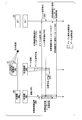
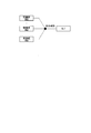
- FIG. 9 is a diagram showing a network configuration when an ONU newly connects to the PON system.
- the OLT is already connected to one or more connected ONUs (hereinafter, referred to as “connected ONUs”).
- One or more unconnected ONUs (hereinafter, referred to as “unconnected ONUs”) perform an initial connection with the OLT by a Discovery process.
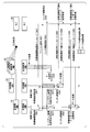
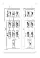
- FIG. 10 is a block diagram showing a configuration of a communication system that executes a Discovery process according to the related art.
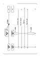
- FIG. 11 is a sequence diagram showing the flow of the process of the Discovery process in the related art.
- FIG. 12 is a flowchart showing a process flow of a Discovery process according to the related art. Based on FIGS. 10 to 12, the processing flow of the Discovery process in the related art will be described below.
- the Discovery process is executed in a state where all the connected ONUs are not transmitting data.
- the message processing unit of the OLT transmits the Discovery_Gate signal to all ONUs via the data signal transmission processing unit, the data signal transmission unit, and the data signal light transmission unit.
- the message processing unit of the unconnected ONU receives the Discovery_Gate signal via the data signal light receiving unit, the data signal receiving unit, and the data signal receiving processing unit.
- the message processing unit of the unconnected ONU Upon receiving the Discovery_Gate signal, the message processing unit of the unconnected ONU transmits a Register_Request signal to the OLT via the data signal transmission processing unit, the data signal transmission unit, and the data signal light transmission unit. At this time, the optical signal is transmitted in a burst to the OLT via the optical signal control command unit, the optical signal output control unit, and the optical signal control unit of the unconnected ONU.
- the message processing unit of the OLT receives the Register_Request signal via the data signal light receiving unit, the data signal receiving unit, and the data signal receiving processing unit. Upon receiving the Register_Request signal, the message processing unit of the OLT recognizes the identifier described in the Discovery_Gate signal. The message processing unit of the OLT transmits the Register signal to the unconnected ONU via the data signal transmission processing unit, the data signal transmission unit, and the data signal light transmission unit.
- the message processing unit of the unconnected ONU receives the Register signal via the data signal light receiving unit, the data signal receiving unit, and the data signal receiving processing unit. Upon receiving the Register signal, the message processing unit of the unconnected ONU transmits a Register_ACK signal to the OLT via the data signal transmission processing unit, the data signal transmission unit, and the data signal light transmission unit.
- the message processing unit of the OLT receives the Register_ACK signal via the data signal light receiving unit, the data signal receiving unit, and the data signal receiving processing unit.
- the Discovery process is completed, the unconnected ONU is registered in the OLT, and the initial connection is completed.
- Ethernet registered trademark
- P2P Point-to-Point
- PON Point-to-Point
- a Discovery process is executed for an initial connection between the OLT / ONU.
- Ethernet registered trademark
- 10G @ Ethernet registered trademark
- the Discovery process cannot be executed when all connected ONUs are not transmitting optical signals. Therefore, there is a problem that the initial connection cannot be performed by using the same technology as the related art.
- the present invention has been made in view of such circumstances, and provides a technology that can perform initial connection only with a standard Ethernet (registered trademark) device when a plurality of network devices are connected in a PON topology.
- the purpose is to provide.
- One embodiment of the present invention is the first communication device in an optical access system in which a first communication device and a plurality of second communication devices communicate with each other by a time-division multiple access method, wherein the first communication device is an Ethernet (registered trademark).
- An Ethernet controller that realizes communication as described above, and when the second communication device makes an initial connection to a network of the optical access system, based on collision detection of optical signals respectively transmitted from the plurality of second communication devices.
- a link failure detection unit that detects the presence or absence of a link failure, and a notification for starting the initial connection process when the link failure detection unit detects that the link failure has not occurred.
- a signal processing unit that outputs an initial connection start notification.
- One embodiment of the present invention is the second communication device in an optical access system in which a first communication device and a plurality of second communication devices communicate with each other by a time-division multiple access method, wherein the second communication device includes Ethernet (registered A first stop command indicating a command for stopping output of an optical signal to the first communication device for a predetermined time when an initial connection to a network of the optical access system and an Ethernet controller for realizing communication as a trademark are performed. And a first stop command unit that outputs a command.
- one aspect of the present invention is the communication device described above, wherein after connecting to the network, an initial connection start notification for starting the initial connection process transmitted from the first communication device is provided.
- the apparatus further includes a first transmission command unit that outputs a first transmission command indicating a command to cause the first communication device to transmit an idle signal when the reception is not performed after a lapse of a predetermined time.
- one aspect of the present invention is the communication device described above, wherein the transmission of the idle signal to the first communication device indicates the occurrence of a link failure transmitted from the first communication device.
- the retransmission command unit that stops the output of the optical signal to the first communication device and outputs a retransmission command for retransmitting the idle signal after an arbitrary time has elapsed. Further prepare.
- one aspect of the present invention is the above communication device, wherein after receiving an initial connection start notification for starting the initial connection process, receiving a link failure occurrence notification indicating the occurrence of a link failure. And a second stop command unit that outputs a second stop command indicating a command for stopping output of the optical signal to the first communication device when the device is already connected to the network.
- one aspect of the present invention is the communication device described above, wherein when receiving a link failure occurrence notification indicating the occurrence of a link failure, the communication device has already been connected to the network. If the connection of the optical signal is stopped and the network is not connected when the link failure occurrence notification is received, after an elapse of an arbitrary time, an initial connection start notification for starting the initial connection process is transmitted.
- the information processing apparatus further includes a second transmission command unit that outputs a second transmission command for transmitting an initial connection response indicating a response to the first communication device to the first communication device.
- One embodiment of the present invention is a communication method by a computer of the first communication device in an optical access system in which a first communication device and a plurality of second communication devices communicate by a time-division multiple access method.
- Realizing communication as Ethernet (registered trademark) and, when the second communication device makes an initial connection to the network of the optical access system, transmitting the light transmitted from each of the plurality of second communication devices.
- One embodiment of the present invention is a communication method by a computer of the second communication device in an optical access system in which a first communication device and a plurality of second communication devices communicate by a time division multiple access method.
- Ethernet registered trademark
- the initial connection can be performed only with standard Ethernet (registered trademark) devices.
- FIG. 1 is a block diagram illustrating a functional configuration of a communication system 1 according to an embodiment of the present invention.
- FIG. 6 is a diagram showing a process flow when connecting a first device in a Discovery process by the communication system 1 according to an embodiment of the present invention.
- FIG. 9 is a diagram showing a process flow when a first ONU and a second or more ONUs are simultaneously connected in a Discovery process by the communication system 1 according to an embodiment of the present invention.
- FIG. 8 is a diagram showing a process flow when one new ONU is connected in a state where one or more ONUs are connected in the Discovery process by the communication system 1 according to an embodiment of the present invention.
- FIG. 6 is a diagram showing a process flow when connecting a first device in a Discovery process by the communication system 1 according to an embodiment of the present invention.
- FIG. 9 is a diagram showing a process flow when a first ONU and a second or more ONUs are simultaneously connected in a Discovery process by the communication system 1 according to
- 4 is a diagram showing a process flow when two new ONUs are connected in a state where one or more ONUs are connected in the Discovery process by the communication system 1 according to an embodiment of the present invention.
- 4 is a flowchart illustrating a flow of a process in a Discovery process performed by the communication system 1.
- 4 is a flowchart illustrating a flow of a process in a Discovery process performed by the communication system 1.
- 4 is a flowchart illustrating a flow of a process in a Discovery process performed by the communication system 1.
- FIG. 2 is a diagram illustrating a network configuration when an ONU newly connects to a PON system.
- FIG. 11 is a block diagram illustrating a configuration of a communication system that executes a Discovery process according to the related art.
- FIG. 13 is a sequence diagram illustrating a flow of a process of a Discovery process in the related art.
- 11 is a flowchart illustrating a flow of a process of a Discovery process according to the related
- FIG. 1 is a block diagram illustrating a functional configuration of a communication system 1 according to an embodiment of the present invention.
- the communication system 1 includes an ONU 10 and an OLT 20.
- the communication system 1 is an optical access system in which an OLT 20 (first communication device) and a plurality of ONUs 10 (second communication devices) communicate with each other by a time division multiple access method.
- the ONU 10 includes an arithmetic processing unit 11, an Ethernet controller 13, and an optical signal transceiver 15.
- the arithmetic processing unit 11 is configured to include a processor such as a CPU (Central Processing Unit). As shown in FIG. 1, the arithmetic processing unit 11 includes a message processing unit 111, a data signal transmission processing unit 112, an optical signal control instruction unit 113, a data signal reception processing unit 114, and an initial connection start waiting instruction unit 115. , An initial connection start processing unit 116, an idle signal retransmission command unit 117, an initial connection response waiting processing adding unit 118, a link failure processing unit 119, and an initial connection response waiting processing unit 120. .
- a processor such as a CPU (Central Processing Unit).
- the arithmetic processing unit 11 includes a message processing unit 111, a data signal transmission processing unit 112, an optical signal control instruction unit 113, a data signal reception processing unit 114, and an initial connection start waiting instruction unit 115.
- the initial connection response waiting processing adding unit 118, the link failure processing unit 119, and the initial connection response waiting processing unit 120 are software programs executed by a processor such as a CPU.
- the message processing unit 111 outputs a control start command and a control end command to the data signal transmission processing unit 112 and the optical signal control command unit 113, respectively.
- the data signal transmission processing unit 112 starts transmission processing on data transmitted from the request source and waiting for transmission (hereinafter referred to as “transmission waiting data”). It is assumed that the transmission waiting data is stored in a temporary storage medium (not shown) provided in the arithmetic processing unit 11 or another functional block of the ONU 10.
- the data signal transmission processing unit 112 transmits the data signal transmission command for executing the transmission of the data signal and the data subjected to the transmission processing to the data signal of the optical signal transceiver 15 via the data signal transmission unit 131 of the Ethernet controller 13.
- the signal is output to the optical transmission unit 151.
- the optical signal control command unit 113 When the control start command is input, the optical signal control command unit 113 outputs an optical signal control command for controlling the output of the optical signal to the optical signal output control unit 132 of the Ethernet controller 13.
- the data signal reception processing unit 114 acquires a data signal based on the optical signal received by the data signal light reception unit 153 from the data signal reception unit 133 via the link failure detection unit 134.
- the initial connection start wait instruction unit 115 outputs an instruction to the optical signal control instruction unit 113 so as not to output an optical signal for a certain period of time during network connection.
- the initial connection start processing unit 116 If the initial connection start processing unit 116 does not receive the initial connection start notification message even after a certain period of time has elapsed after the network connection, the initial connection start processing unit 116 issues a command to the optical signal control command unit 113 to output an idle signal. Output.
- the idle signal retransmission command unit 117 stops outputting the optical signal when receiving the link failure notification for the transmission of the idle signal. Then, after a random (arbitrary) time has elapsed, the idle signal retransmission command unit 117 outputs a command for re-outputting the idle signal to the optical signal control command unit 113.
- the initial connection response waiting process adding unit 118 When receiving the initial connection start notification message before the re-output of the idle signal, the initial connection response waiting process adding unit 118 again transmits the data signal transmission processing unit 112 after a random (arbitrary) time elapses. Output an instruction for transmitting an initial connection response message.
- the link failure processing unit 119 When receiving the link failure notification after receiving the initial connection start notification message, the link failure processing unit 119 causes the optical signal control command unit 113 to stop outputting the optical signal when the link failure processing unit 119 is connected to the network. Output instructions for When receiving the link failure notification for the transmission of the idle signal, the initial connection response waiting processing unit 120 stops outputting the optical signal. Then, after a random (arbitrary) time has elapsed, the initial connection response waiting processing unit 120 outputs a command for transmitting an initial connection response message to the data signal transmission processing unit 112.
- the Ethernet controller 13 is, for example, a circuit (Ethernet (registered trademark)) among circuits that enable data communication by a MAC (Media Access Control) layer and a PHY layer (physical layer) protocol, which are mounted on a network interface and a network device, for example. ) Is a circuit that realizes communication. As shown in FIG. 1, the Ethernet controller 13 includes a data signal transmission unit 131, an optical signal output control unit 132, a data signal reception unit 133, and a link failure detection unit 134.
- Ethernet registered trademark
- PHY layer physical layer
- the data signal transmission unit 131 outputs an electric signal based on the data signal input from the data signal transmission processing unit 112 to the data signal light transmission unit 151.
- the optical signal output control unit 132 controls the optical signal control unit 152 based on the electric signal output from the data signal transmission unit 131 to the data signal optical transmission unit 151, so that the data signal optical transmission unit 151 The output of the transmitted optical signal is controlled.
- the data signal receiving unit 133 acquires an electric signal based on the optical signal received by the data signal light receiving unit 153 from the link failure detecting unit 134, and outputs a data signal based on the acquired electric signal to the data signal reception processing unit 114. .
- the link failure detecting unit 134 acquires an electric signal based on the optical signal received by the data signal light receiving unit 153, and detects the presence or absence of a link failure notification.
- the link failure detection unit 134 outputs the acquired link failure notification to the link failure processing unit 119. Further, the link failure detection unit 134 outputs a data signal based on the acquired electric signal to the data signal reception unit 133.
- the optical signal transceiver 15 is a device having a physical medium dependent unit function capable of outputting an electric signal as an optical signal.
- the optical signal transceiver 15 is, for example, an optical module such as SFP (Small Form-factor Pluggable / Mini-GBIC) / SFP + or an optical module mounted on a printed circuit board.
- the optical signal transceiver 15 includes a data signal light transmitting unit 151, an optical signal control unit 152, and a data signal light receiving unit 153.
- the data signal light transmission unit 151 transmits an optical signal based on the electric signal input from the data signal transmission unit 131 to the OLT 20 via a network under the control of the optical signal control unit 152.
- the optical signal control unit 152 switches ON / OFF of the optical pulse based on the values of 0 and 1 of the electric signal input to the data signal optical transmission unit 151 under the control of the optical signal output control unit 132. Execute. Thereby, the optical signal is transmitted to the OLT 20.
- the ONU 10 can transmit a data signal to the OLT 20 as an optical burst signal without using an optical line terminal.
- the data signal light receiving unit 153 receives the optical signal transmitted from the OLT 20.
- the data signal light receiving section 153 outputs an electric signal based on the received optical signal to the link failure detecting section 134.
- the OLT 20 includes an arithmetic processing unit 21, an Ethernet controller 23, and an optical signal transceiver 25.
- the arithmetic processing unit 21 includes, for example, a processor such as a CPU. As shown in FIG. 1, the arithmetic processing unit 21 includes a message processing unit 211, a data signal transmission processing unit 212, a data signal reception processing unit 213, and an idle signal processing unit 214.
- the message processing unit 211 outputs a control start command and a control end command to the data signal transmission processing unit 212 and the data signal reception processing unit 213.
- the data signal transmission processing unit 212 starts transmission processing for data waiting to be transmitted. It is assumed that the transmission waiting data is stored in a temporary storage medium (not shown) provided in the arithmetic processing unit 21 or another functional block of the OLT 20.
- the data signal transmission processing unit 212 transmits the data signal transmission command for executing the transmission of the data signal and the data subjected to the transmission processing to the data signal of the optical signal transceiver 25 via the data signal transmission unit 231 of the Ethernet controller 23. Output to the optical transmission unit 251.
- the data signal reception processing unit 213 acquires a data signal based on the optical signal received by the data signal light reception unit 252 from the data signal reception unit 232 via the link failure detection unit 233.
- the idle signal processing unit 214 receives the idle signal regarding the initial connection, and outputs a transmission instruction of the initial connection start notification message to the data signal transmission processing unit 212 in a state where no link failure has occurred.
- the Ethernet controller 23 implements communication as Ethernet (registered trademark) among circuits that enable data communication by a protocol of a MAC layer and a PHY layer (physical layer) mounted on a network interface and a network device, for example. Circuit. As shown in FIG. 1, the Ethernet controller 23 is configured to include a data signal transmission unit 231, a data signal reception unit 232, and a link failure detection unit 233.
- the data signal transmission unit 231 outputs an electric signal based on the data signal input from the data signal transmission processing unit 212 to the data signal light transmission unit 251.
- the data signal receiving unit 232 acquires an electric signal based on the optical signal received by the data signal light receiving unit 252 from the link failure detecting unit 233, and outputs a data signal based on the received electric signal to the data signal reception processing unit 213.
- the link failure detection unit 233 acquires an electric signal based on the optical signal received by the data signal light receiving unit 252, and detects the presence or absence of a link failure. Further, the link failure detecting unit 233 outputs the obtained electric signal to the data signal receiving unit 232.
- the optical signal transceiver 25 is a device having a physical medium dependent unit function capable of outputting an electric signal as an optical signal.
- the optical signal transceiver 25 is, for example, an optical module such as SFP / SFP + or an optical module mounted on a printed circuit board.
- the optical signal transceiver 25 includes a data signal light transmitting unit 251 and a data signal light receiving unit 252.
- the data signal light transmission unit 251 transmits an optical signal based on the electric signal input from the data signal transmission unit 231 to the ONU 10 via the network.
- the data signal light receiving section 252 receives the light signal transmitted from the OLT 10.
- the data signal light receiving section 252 outputs an electric signal based on the received optical signal to the link failure detecting section 233.
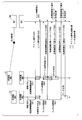
- FIG. 2 is a diagram showing a process flow when a first device is connected in the Discovery process by the communication system 1 according to an embodiment of the present invention.
- the unconnected ONU 10 connected to the network as the first ONU is connected to the network (step S10), and waits for the start of the initial connection without outputting an optical signal according to the instruction of the initial connection start wait instruction unit 115 (step S10).
- Step S11) The unconnected ONU 10 transmits an idle signal according to a command of the initial connection start waiting command unit 115 after not receiving the initial connection start notification message for a certain period of time (step S12).
- the OLT 20 that has received the idle signal transmits an initial connection start notification message according to an instruction of the idle signal processing unit 214 (Step S13).
- the unconnected ONU 10 that has received the initial connection start notification message transmits an initial connection response message according to a command from the message processing unit 111 (step S14).
- the OLT 20 that has received the initial connection response message transmits an initial connection completion notification message according to an instruction of the message processing unit 211 (step S15).
- the initial connection is completed when the unconnected ONU 10 receives the initial connection completion notification message.
- FIG. 3 is a diagram showing a process flow when a first ONU and two or more ONUs are simultaneously connected in a Discovery process by the communication system 1 according to an embodiment of the present invention.
- the unconnected ONUs 10 that are initially connected to the network as the first ONU and the second or more ONUs at the same time are connected to the network (step S20), and then output an optical signal in accordance with a command from the initial connection start waiting command unit 115. Without waiting for the start of the initial connection (step S21).
- the unconnected ONU 10 transmits an idle signal to the OLT 20 according to a command of the initial connection start waiting command unit 115 after not receiving the initial connection start notification message for a certain period of time (step S22).
- the idle signals transmitted from the two unconnected ONUs 10 are collided and received by the OLT 10. Therefore, the OLT 20 detects a link failure by the link failure detection unit 233 (Step S23).
- the OLT 20 transmits a link failure notification to the unconnected ONU 10 via the data signal light transmission unit 251 (Step S24).
- the unconnected ONU 10 that has received the link failure notification recognizes that a link failure has occurred due to the transmission of the idle signal, and stops outputting the optical signal (step S25).
- the unconnected ONU 10 retransmits the idle signal to the OLT 20 according to the command of the idle signal retransmission command unit 117 after a random (arbitrary) time elapses for the device-specific value (step S26) (step S27).
- the OLT 20 that has received the idle signal from one unconnected ONU 10 transmits an initial connection start notification message to the unconnected ONU 10 according to an instruction of the idle signal processing unit 214 (step S28).
- the unconnected ONU 10 that has received the initial connection start notification message transmits an initial connection response message to the OLT 20 according to a command of the message processing unit 111 (step S29).
- the OLT 20 that has received the initial connection response message transmits an initial connection completion notification message to the unconnected ONU 10 according to an instruction of the message processing unit 211 (step S30).
- the initial connection is completed when the unconnected ONU 10 receives the initial connection completion notification message.
- the unconnected ONU 10 that has received the initial connection start notification message before transmitting the idle signal again performs the initial connection after a random (arbitrary) time elapses with respect to the device-specific value (step S31).
- An initial connection response message is transmitted to the OLT 20 according to a command from the response waiting process adding unit 118 (step S32).
- the OLT 20 that has received the initial connection response message transmits an initial connection completion notification message to the unconnected ONU 10 according to a command from the message processing unit 211 (step S33).
- the initial connection is completed when the unconnected ONU 10 receives the initial connection completion notification message.
- FIG. 4 is a diagram showing a flow of a process when a new ONU is connected in a state where one or more ONUs are connected in the Discovery process by the communication system 1 according to the embodiment of the present invention. is there.
- the unconnected ONU 10 newly connected to the network after connecting to the network (step S40), waits for the start of the initial connection without outputting an optical signal according to the instruction of the initial connection start wait instruction unit 115 (step S41).
- the unconnected ONU 10 that has received the initial connection start notification message (step S42) transmitted by the command of the message processing unit 211 of the OLT 20 during a certain time period receives an idle connection to the OLT 20 according to the command of the initial connection start waiting command unit 115.
- Signal transmission is started (step S43).
- the OLT 20 that has received the idle signal detects a link failure by the link failure detection unit 233 (Step S44).
- the OLT 20 transmits a link failure notification to the connected ONU 10 and the unconnected ONU 10 via the data signal light transmission unit 251 (Step S45).
- the connected ONU 10 that has received the link failure notification stops outputting the optical signal in accordance with the instruction of the link failure processing unit 119 (step S46).
- the unconnected ONU 10 transmits an initial connection response message to the initial connection start message to the OLT 20 according to an instruction of the message processing unit 111 (step S47).
- the OLT 20 that has received the initial connection response message transmits an initial connection completion notification message to the unconnected ONU 10 according to a command of the message processing unit 211 (step S48).
- the initial connection is completed when the unconnected ONU 10 receives the initial connection completion notification message.
- FIG. 5 is a diagram showing a process flow when two new ONUs are connected in a state where one or more ONUs are connected in the Discovery process by the communication system 1 according to an embodiment of the present invention. is there.
- the unconnected ONUs 10 that are initially connected to the network simultaneously as the first ONU and the second or more ONUs that are newly connected to the network are connected to the network (step S50), and then the instruction of the initial connection start wait instruction unit 115 is issued. As a result, it waits for the start of the initial connection without outputting the optical signal (step S51).
- the unconnected ONU 10 that has received the initial connection start notification message (step S52) transmitted by the command of the message processing unit 211 of the OLT 20 during a certain period of time receives the idle connection to the OLT 20 according to the command of the initial connection start waiting command unit 115. Signal transmission is started (step S53).
- the OLT 20 that has received the idle signal detects a link failure by the link failure detection unit 233 (Step S54). Then, the OLT 20 transmits a link failure notification to the connected ONU 10 and the unconnected ONU 10 via the data signal light transmission unit 251 (Step S55). The connected ONU 10 that has received the link failure notification stops outputting the optical signal in accordance with the instruction of the link failure processing unit 119 (step S56).
- the unconnected ONU 10 stops transmitting the optical signal to the OLT 20 according to the instruction of the initial connection response waiting process adding unit 118 (step S57). After a random (arbitrary) time has elapsed (step S58), the unconnected ONU 10 transmits an idle signal, and then transmits an initial connection response message to the OLT 20 according to a command of the message processing unit 111 (step S59). ).
- the OLT 20 that has received the initial connection response message transmits an initial connection completion notification message to the unconnected ONU 10 according to a command of the message processing unit 211 (step S60).
- the initial connection is completed when the unconnected ONU 10 receives the initial connection completion notification message.
- the above flow is repeated until the initial connection of all the unconnected ONUs 20 is completed.
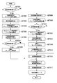
- FIG. 6 is a flowchart showing the flow of processing in the Discovery process by the communication system 1.
- the connected ONUs 10 transmit an idle signal to the OLT 20 (ACT002).
- an initial connection process A shown in FIG. 7 is performed (ACT003).
- the OLT 20 transmits an initial connection start notification message to the unconnected ONU 10 (ACT 101).
- the unconnected ONU 10 receives the initial connection start notification message transmitted from the OLT 20 (ACT 102).
- the unconnected ONU 10 transmits an idle signal to the OLT 20 (ACT004).
- the OLT 20 detects a link failure and transmits a link failure notification to all the connected ONUs 10 (ACT005). All the connected ONUs 10 stop outputting the optical signal (ACT006).
- the ONU 10 waits for a random (arbitrary) time to elapse (ACT008). If the number of the unconnected ONUs 10 is less than two (that is, the number of the unconnected ONUs 10 is one) (ACT 007 No), the ONU 10 does not wait for the random (arbitrary) time to elapse. Not performed.
- the initial connection process B shown in FIG. 8 is repeated by the number of unconnected ONUs 10 (ACT017).
- the unconnected ONU 10 transmits an initial connection response message to the OLT 20 (ACT 201).
- the OLT 20 receives the initial connection response message transmitted from the unconnected ONU 10 (ACT 202).
- the OLT 20 transmits an initial connection completion notification message to the unconnected ONU 10 (ACT 203).
- the unconnected ONU 10 receives the initial connection completion notification message transmitted from the OLT 20 (ACT 204).
- the unconnected ONU 10 waits for the start of the initial connection without outputting an optical signal (ACT009).
- the unconnected ONU 10 transmits an idle signal to the OLT 20 (ACT010).
- the OLT 20 detects a link failure and transmits a link failure notification to all the connected ONUs 10 (ACT012).
- All the unconnected ONUs 10 stop outputting the optical signal (ACT013).
- the ONU 10 waits for a random (arbitrary) time to elapse (ACT014).
- One of the unconnected ONUs 10 transmits an idle signal to the OLT 20 (ACY015).
- the initial connection process A described above with reference to FIG. 7 is performed (ACT016).
- the initial connection process B described above with reference to FIG. 8 is repeated by the number of unconnected ONUs 10 (ACT017).
- the processing of the flowcharts shown in FIGS. 6 to 8 is completed.
- an Ethernet (registered trademark) device ONU
- an optical signal transmitted by another ONU does not collide with an optical signal transmitted by its own ONU.
- control is required to prevent the transmission of the optical signal until the initial connection starts.
- a means that can execute an initial connection even when the link failure notification function operates is required.
- the ONU 10 composed of Ethernet (registered trademark) controls so as not to transmit an optical signal when connected to the OLT 20, and the connected ONU 10 that has received the link failure notification outputs the optical signal. Control to stop.
- initial connection can be performed only with standard Ethernet (registered trademark) devices.
- a part or all of the ONU 10 and the OLT 20 in the above-described embodiment may be realized by a computer.
- a program for realizing this control function may be recorded on a computer-readable recording medium, and the program recorded on this recording medium may be read by a computer system and executed.
- the “computer system” is a computer system built in the ONU 10 and the OLT 20 and includes hardware such as an OS and peripheral devices.
- the “computer-readable recording medium” refers to a portable medium such as a flexible disk, a magneto-optical disk, a ROM, and a CD-ROM, and a storage device such as a hard disk built in a computer system.
- the "computer-readable recording medium” is a medium that holds the program dynamically for a short time, such as a communication line when transmitting the program through a communication line such as a network such as the Internet or a telephone line,
- a program holding a program for a certain period of time such as a volatile memory in a computer system serving as a server or a client, may be included.
- the above-mentioned program may be for realizing a part of the above-mentioned functions, or may be for realizing the above-mentioned functions in combination with a program already recorded in a computer system.
- a part or all of the ONU 10 and the OLT 20 in the above-described embodiment may be realized as an integrated circuit such as an LSI (Large Scale Integration).
- LSI Large Scale Integration
- Each functional block of the ONU 10 and the OLT 20 may be individually formed into a processor, or a part or all may be integrated into a processor.
- the method of circuit integration is not limited to an LSI, and may be realized by a dedicated circuit or a general-purpose processor. Further, in the case where a technology for forming an integrated circuit that replaces the LSI appears due to the progress of semiconductor technology, an integrated circuit based on the technology may be used.
- SYMBOLS 1 Communication system, 10 ... ONU (Optical subscriber line terminating equipment), 11 ... Operation processing part, 13 ... Ethernet controller, 15 ... Optical signal transceiver, 20 ... OLT (Optical subscriber line terminal equipment), 21 ...
Landscapes
- Engineering & Computer Science (AREA)
- Computer Networks & Wireless Communication (AREA)
- Signal Processing (AREA)
- Small-Scale Networks (AREA)
Abstract
第1の通信装置と複数の第2の通信装置とが時分割多元接続方式により通信を行う光アクセスシステムにおける前記第1の通信装置は、イーサネット(登録商標)として通信を実現するイーサネットコントローラと、前記第2の通信装置が前記光アクセスシステムのネットワークに初期接続を行う場合において、前記複数の第2の通信装置からそれぞれ送信された光信号の衝突検知に基づいてリンク障害の発生の有無を検知するリンク障害検知部と、前記リンク障害検知部によって前記リンク障害が発生していないことが検知された場合、前記初期接続の処理を開始させるための通知を示す初期接続開始通知を出力する信号処理部と、を備える。
Description
本発明は、通信装置及び通信方法に関する。
Ethernet(イーサネット)(登録商標)は、世界的に使用されている有線ネットワークプロトコルであり、多くの標準的なネットワーク機器によって用いられている。
その中でも、光伝送技術を適用した、物理層を光インターフェースで規定しているEthernet(登録商標)は、専らP2P(ポイント・ツー・ポイント)方式の通信において用いられており、長距離高速通信を可能にするインターフェースとして普及している。
その中でも、光伝送技術を適用した、物理層を光インターフェースで規定しているEthernet(登録商標)は、専らP2P(ポイント・ツー・ポイント)方式の通信において用いられており、長距離高速通信を可能にするインターフェースとして普及している。
複数のネットワーク機器を収容する、特に長距離伝送を行うアクセスネットワークにおいて、上記P2Pのネットワークトポロジを用いた場合、光ファイバの敷設コスト及び局内装置の占有面積が増加する。そこで、PON(Passive Optical Network)トポロジを用いたP2MP(ポイント・ツー・マルチポイント)方式の通信システムが、PONシステムとしてアクセスネットワークに用いられている。PONシステムは、光ファイバと光加入者線端局装置(OLT;Optical Line Terminal)を、複数の光加入者線終端装置(ONU;Optical Network Unit)で共有することにより、光ファイバの敷設コストとOLTの占有面積とを削減することができる、このPONシステムの構成は、IEEE(Institute of Electrical and Electronics Engineers)によって規定されている。
従来のPONシステムでは、OLT/ONU間の初期接続のために、Discoveryプロセスを実行する。Discoveryプロセスとは、OLTがONUを新たに登録する方法である。この登録に基づいて、OLT/ONU間の初期接続が実行される(非特許文献1参照)。
図9は、ONUが新たにPONシステムに接続する際のネットワーク構成を示す図である。図9に示すように、OLTは、既に1台以上の接続済みのONU(以下「接続済ONU」という。)に接続している。1台以上の未接続のONU(以下「未接続ONU」という。)が、Discoveryプロセスにより、OLTとの初期接続を行う。
図10は、従来技術におけるDiscoveryプロセスを実行する通信システムの構成を示すブロック図である。また、図11は、従来技術におけるDiscoveryプロセスの処理の流れを示すシーケンス図である。また、図12は、従来技術におけるDiscoveryプロセスの処理の流れを示すフローチャートである。図10~図12に基づいて、従来技術におけるDiscoveryプロセスの処理の流れを以下に示す。
Discoveryプロセスは、全接続済ONUがデータ送信をしていない状態で実行される。Discoveryプロセスが開始されると、OLTのメッセージ処理部は、データ信号送信処理部、データ信号送信部及びデータ信号光送信部を介して、Discovery_Gate信号を全ONUに向けて送信する。
未接続ONUのメッセージ処理部は、データ信号光受信部、データ信号受信部及びデータ信号受信処理部を介して、Discovery_Gate信号を受信する。
未接続ONUのメッセージ処理部は、データ信号光受信部、データ信号受信部及びデータ信号受信処理部を介して、Discovery_Gate信号を受信する。
未接続ONUのメッセージ処理部は、Discovery_Gate信号を受信すると、データ信号送信処理部、データ信号送信部及びデータ信号光送信部を介して、Register_Request信号をOLTに向けて送信する。この際、未接続ONUの、光信号制御命令部、光信号出力制御部及び光信号制御部を介して、OLTに向けて光信号がバースト的に送信される。
OLTのメッセージ処理部は、データ信号光受信部、データ信号受信部及びデータ信号受信処理部を介して、Register_Request信号を受信する。OLTのメッセージ処理部は、Register_Request信号を受信すると、Discovery_Gate信号に記載された識別子を認識する。OLTのメッセージ処理部は、データ信号送信処理部、データ信号送信部及びデータ信号光送信部を介して、Register信号を未接続ONUに向けて送信する。
未接続ONUのメッセージ処理部は、データ信号光受信部、データ信号受信部及びデータ信号受信処理部を介して、Register信号を受信する。未接続ONUのメッセージ処理部は、Register信号を受信すると、データ信号送信処理部、データ信号送信部及びデータ信号光送信部を介して、Register_ACK信号をOLTに向けて送信する。
OLTのメッセージ処理部は、データ信号光受信部、データ信号受信部及びデータ信号受信処理部を介して、Register_ACK信号を受信する。
以上の処理により、Discoveryプロセスが完了し、未接続ONUがOLTに登録され、初期接続が完了する。
以上の処理により、Discoveryプロセスが完了し、未接続ONUがOLTに登録され、初期接続が完了する。
"IEEE Standard for Ethernet SECTION FIVE", IEEE Std 802.3TM-2015", IEEE Computer Society, pp.310-343,675-709, 2015年
"IEEE Standard for Ethernet SECTION FOUR", IEEE Std 802.3TM-2015", IEEE Computer Society, pp.321-323, 2015年
ところで、従来技術において、物理層を光インターフェースで規定したEthernet(登録商標)は、P2P(Point-to-Point)方式の長距離高速通信等に用いられる。アクセスネットワークにP2Pのネットワークトポロジを用いた場合、光ファイバの敷設コストの増加が懸念される。そのため、PONトポロジを用いたP2MP(Point-to-MultiPoint)を行う方式が、PONシステムとしてアクセスネットワークに用いられている。
PONシステムでは、OLT/ONU間の初期接続のために、Discoveryプロセスが実行される。汎用装置であるイーサネット(登録商標)機器を用いてPONシステムを実現した場合、特に10G Ethernet(登録商標)機器を用いたONUは、OLTから制御される前に光信号を送出する。そのため、自己のONUが送信する光信号と他のONUが送信する光信号とが衝突する。これにより、初期接続を行うことができない。また、10G Ethernet(登録商標)の必須規格であるリンク障害通知機能による制限から、接続済ONU全てが光信号を送信していない状態ではDiscoveryプロセスを実行することができない。そのため、従来と同様の技術を用いると、初期接続を行うことができないという課題がある。
本発明は、このような事情を考慮してなされたものであり、複数ネットワーク機器をPONトポロジで接続した際に、標準的なEthernet(登録商標)機器のみで初期接続を行うことができる技術を提供することを目的とする。
本発明の一態様は、第1の通信装置と複数の第2の通信装置とが時分割多元接続方式により通信を行う光アクセスシステムにおける前記第1の通信装置であって、イーサネット(登録商標)として通信を実現するイーサネットコントローラと、前記第2の通信装置が前記光アクセスシステムのネットワークに初期接続を行う場合において、前記複数の第2の通信装置からそれぞれ送信された光信号の衝突検知に基づいてリンク障害の発生の有無を検知するリンク障害検知部と、前記リンク障害検知部によって前記リンク障害が発生していないことが検知された場合、前記初期接続の処理を開始させるための通知を示す初期接続開始通知を出力する信号処理部と、を備える通信装置である。
また、本発明の一態様は、第1の通信装置と複数の第2の通信装置とが時分割多元接続方式により通信を行う光アクセスシステムにおける前記第2の通信装置であって、イーサネット(登録商標)として通信を実現するイーサネットコントローラと、前記光アクセスシステムのネットワークに初期接続を行う場合において、一定時間、前記第1の通信装置に対する光信号の出力を中止させるための命令を示す第1中止命令を出力する第1中止命令部と、を備える通信装置である。
また、本発明の一態様は、上記の通信装置であって、前記ネットワークに接続した後、前記第1の通信装置から送信される前記初期接続の処理を開始させるための初期接続開始通知を前記一定時間が経過しても受信しなかった場合、前記第1の通信装置へのアイドル信号の送信をさせるための命令を示す第1送信命令を出力する第1送信命令部をさらに備える。
また、本発明の一態様は、上記の通信装置であって、前記第1の通信装置への前記アイドル信号の送信に対して前記第1の通信装置から送信される、リンク障害の発生を示すリンク障害発生通知を受信した場合、前記第1の通信装置への光信号の出力を中止させ、任意の時間が経過した後に、前記アイドル信号を再送させるための再送命令を出力する再送命令部をさらに備える。
また、本発明の一態様は、上記の通信装置であって、前記初期接続の処理を開始させるための初期接続開始通知を受信した後、リンク障害の発生を示すリンク障害発生通知を受信した際に前記ネットワークに接続済みである場合、前記第1の通信装置に対する光信号の出力を中止させるための命令を示す第2中止命令を出力する第2中止命令部をさらに備える。
また、本発明の一態様は、上記の通信装置であって、リンク障害の発生を示すリンク障害発生通知を受信した際に前記ネットワークに接続済みである場合、前記第1の通信装置への前記光信号の出力を中止させ、前記リンク障害発生通知を受信した際に前記ネットワークに接続していない場合、任意の時間が経過した後に、前記初期接続の処理を開始させるための初期接続開始通知に対する前記第1の通信装置への応答を示す初期接続応答を前記第1の通信装置へ送信させるための第2送信命令を出力する第2送信命令部をさらに備える。
また、本発明の一態様は、第1の通信装置と複数の第2の通信装置とが時分割多元接続方式により通信を行う光アクセスシステムにおける前記第1の通信装置のコンピュータによる通信方法であって、イーサネット(登録商標)として通信を実現するステップと、前記第2の通信装置が前記光アクセスシステムのネットワークに初期接続を行う場合において、前記複数の第2の通信装置からそれぞれ送信された光信号の衝突検知に基づいてリンク障害の発生の有無を検知するステップと、前記リンク障害が発生していないことが検知された場合、前記初期接続の処理を開始させるための通知を示す初期接続開始通知を出力するステップと、を有する通信方法である。
また、本発明の一態様は、第1の通信装置と複数の第2の通信装置とが時分割多元接続方式により通信を行う光アクセスシステムにおける前記第2の通信装置のコンピュータによる通信方法であって、イーサネット(登録商標)として通信を実現するステップと、前記光アクセスシステムのネットワークに初期接続を行う場合において、一定時間、前記第1の通信装置に対する光信号の出力を中止させるための命令を示す中止命令を出力するステップと、を有する通信方法である。
本発明によれば、複数ネットワーク機器をPONトポロジで接続した際に、標準的なEthernet(登録商標)機器のみで初期接続を行うことができる。
<実施形態>
以下、本発明の一実施形態について、図面を参照しながら説明する。
以下、本発明の一実施形態について、図面を参照しながら説明する。
[通信システムの機能構成]
図1は、本発明の一実施形態に係る通信システム1の機能構成を示すブロック図である。図1に示すように、通信システム1は、ONU10と、OLT20と、を含んで構成される。通信システム1は、OLT20(第1の通信装置)と複数のONU10(第2の通信装置)とが時分割多元接続方式により通信を行う光アクセスシステムである。
図1は、本発明の一実施形態に係る通信システム1の機能構成を示すブロック図である。図1に示すように、通信システム1は、ONU10と、OLT20と、を含んで構成される。通信システム1は、OLT20(第1の通信装置)と複数のONU10(第2の通信装置)とが時分割多元接続方式により通信を行う光アクセスシステムである。
ONU10は、演算処理部11と、イーサネットコントローラ13と、光信号送受信器15と、を含んで構成される。
演算処理部11は、例えば、CPU(Central Processing Unit;中央演算処理装置)等のプロセッサを含んで構成される。図1に示すように、演算処理部11は、メッセージ処理部111と、データ信号送信処理部112と、光信号制御命令部113と、データ信号受信処理部114と、初期接続開始待ち命令部115と、初期接続開始処理部116と、アイドル信号再送命令部117と、初期接続応答待ち処理追加部118と、リンク障害処理部119と、初期接続応答待ち処理部120と、を含んで構成される。
なお、メッセージ処理部111、データ信号送信処理部112、光信号制御命令部113、データ信号受信処理部114、初期接続開始待ち命令部115、初期接続開始処理部116、アイドル信号再送命令部117、初期接続応答待ち処理追加部118、リンク障害処理部119及び初期接続応答待ち処理部120は、CPU等のプロセッサによって実行されるソフトウェアプログラムである。
メッセージ処理部111は、データ信号送信処理部112及び光信号制御命令部113に対して、それぞれ制御開始命令及び制御終了命令を出力する。
データ信号送信処理部112は、制御開始命令が入力されると、要求元から送信されて送信待ちとなっているデータ(以下「送信待ちデータ」という。)に対する送信処理を開始する。なお、送信待ちデータは、演算処理部11あるいはONU10の他の機能ブロックが備える一時記憶媒体(図示せず)に記憶されているものとする。データ信号送信処理部112は、データ信号の送信を実行させるためのデータ信号送信命令及び送信処理されたデータを、イーサネットコントローラ13のデータ信号送信部131を介して、光信号送受信器15のデータ信号光送信部151へ向けて出力する。
データ信号送信処理部112は、制御開始命令が入力されると、要求元から送信されて送信待ちとなっているデータ(以下「送信待ちデータ」という。)に対する送信処理を開始する。なお、送信待ちデータは、演算処理部11あるいはONU10の他の機能ブロックが備える一時記憶媒体(図示せず)に記憶されているものとする。データ信号送信処理部112は、データ信号の送信を実行させるためのデータ信号送信命令及び送信処理されたデータを、イーサネットコントローラ13のデータ信号送信部131を介して、光信号送受信器15のデータ信号光送信部151へ向けて出力する。
光信号制御命令部113は、制御開始命令が入力されると、光信号の出力の制御を実行させるための光信号制御命令を、イーサネットコントローラ13の光信号出力制御部132へ出力する。
データ信号受信処理部114は、データ信号光受信部153が受信した光信号に基づくデータ信号を、リンク障害検知部134を介してデータ信号受信部133から取得する。
初期接続開始待ち命令部115は、ネットワーク接続時に、一定時間、光信号の出力をしないよう光信号制御命令部113に対して命令を出力する。
データ信号受信処理部114は、データ信号光受信部153が受信した光信号に基づくデータ信号を、リンク障害検知部134を介してデータ信号受信部133から取得する。
初期接続開始待ち命令部115は、ネットワーク接続時に、一定時間、光信号の出力をしないよう光信号制御命令部113に対して命令を出力する。
初期接続開始処理部116は、ネットワーク接続後、一定時間が経過しても初期接続開始通知メッセージを受信しなかった場合、光信号制御命令部113に対して、アイドル信号を出力させるための命令を出力する。
アイドル信号再送命令部117は、アイドル信号の送信に対してリンク障害通知を受信した際に、光信号の出力を中止する。そして、アイドル信号再送命令部117は、ランダムな(任意の)時間が経過した後、光信号制御命令部113に対して、アイドル信号を再出力させるための命令を出力する。
アイドル信号再送命令部117は、アイドル信号の送信に対してリンク障害通知を受信した際に、光信号の出力を中止する。そして、アイドル信号再送命令部117は、ランダムな(任意の)時間が経過した後、光信号制御命令部113に対して、アイドル信号を再出力させるための命令を出力する。
初期接続応答待ち処理追加部118は、上記アイドル信号の再出力よりも前に初期接続開始通知メッセージを受信した場合、再度、ランダムな(任意の)時間が経過した後、データ信号送信処理部112に対して、初期接続応答メッセージを送信させるための命令を出力する。
リンク障害処理部119は、初期接続開始通知メッセージを受信した後にリンク障害通知を受信した場合、ネットワークに接続済みの場合には、光信号制御命令部113に対して、光信号の出力を中止させるための命令を出力する。
初期接続応答待ち処理部120は、アイドル信号の送信に対してリンク障害通知を受信した場合、光信号の出力を中止する。そして、初期接続応答待ち処理部120は、ランダムな(任意の)時間が経過した後、データ信号送信処理部112に対して、初期接続応答メッセージを送信させるための命令を出力する。
初期接続応答待ち処理部120は、アイドル信号の送信に対してリンク障害通知を受信した場合、光信号の出力を中止する。そして、初期接続応答待ち処理部120は、ランダムな(任意の)時間が経過した後、データ信号送信処理部112に対して、初期接続応答メッセージを送信させるための命令を出力する。
イーサネットコントローラ13は、例えばネットワークインターフェース及びネットワーク機器に実装されている、MAC(Media Access Control)層及びPHY層(物理層)のプロトコルでデータの通信を可能にする回路のうち、特にEthernet(登録商標)として通信を実現する回路である。図1に示すように、イーサネットコントローラ13は、データ信号送信部131と、光信号出力制御部132と、データ信号受信部133と、リンク障害検知部134と、を含んで構成される。
データ信号送信部131は、データ信号送信処理部112から入力されたデータ信号に基づく電気信号を、データ信号光送信部151へ出力する。ここで、光信号出力制御部132は、データ信号送信部131からデータ信号光送信部151へ出力される電気信号に基づいて光信号制御部152を制御することにより、データ信号光送信部151から送信される光信号の出力制御を行う。
データ信号受信部133は、データ信号光受信部153が受信した光信号に基づく電気信号をリンク障害検知部134から取得し、取得した電気信号に基づくデータ信号をデータ信号受信処理部114へ出力する。
リンク障害検知部134は、データ信号光受信部153が受信した光信号に基づく電気信号を取得し、リンク障害通知の有無を検知する。リンク障害検知部134は、取得したリンク障害通知をリンク障害処理部119へ出力する。
また、リンク障害検知部134は、取得した電気信号に基づくデータ信号をデータ信号受信部133へ出力する。
データ信号受信部133は、データ信号光受信部153が受信した光信号に基づく電気信号をリンク障害検知部134から取得し、取得した電気信号に基づくデータ信号をデータ信号受信処理部114へ出力する。
リンク障害検知部134は、データ信号光受信部153が受信した光信号に基づく電気信号を取得し、リンク障害通知の有無を検知する。リンク障害検知部134は、取得したリンク障害通知をリンク障害処理部119へ出力する。
また、リンク障害検知部134は、取得した電気信号に基づくデータ信号をデータ信号受信部133へ出力する。
光信号送受信器15は、電気信号を光信号として出力可能な物理媒体依存部機能を有した機器である。具体的には、光信号送受信器15は、例えば、SFP(Small Form-factor Pluggable/Mini-GBIC)/SFP+等の光モジュール、あるいは、プリント基板上に実装された光モジュールである。図1に示すように、光信号送受信器15は、データ信号光送信部151と、光信号制御部152と、データ信号光受信部153と、を含んで構成される。
データ信号光送信部151は、光信号制御部152による制御のもと、データ信号送信部131から入力された電気信号に基づく光信号を、ネットワークを介してOLT20へ送信する。
光信号制御部152は、光信号出力制御部132による制御のもと、データ信号光送信部151へ入力された電気信号の0及び1の値を踏まえて、光パルスのON/OFFの切り替えを実行する。これにより、OLT20へ向けて光信号が送信される。上記の構成により、ONU10は、光回線終端装置を用いずに、データ信号を光バースト信号としてOLT20へ送信することができる。
データ信号光受信部153は、OLT20から送信された光信号を受信する。データ信号光受信部153は、受信した光信号に基づく電気信号をリンク障害検知部134へ出力する。
光信号制御部152は、光信号出力制御部132による制御のもと、データ信号光送信部151へ入力された電気信号の0及び1の値を踏まえて、光パルスのON/OFFの切り替えを実行する。これにより、OLT20へ向けて光信号が送信される。上記の構成により、ONU10は、光回線終端装置を用いずに、データ信号を光バースト信号としてOLT20へ送信することができる。
データ信号光受信部153は、OLT20から送信された光信号を受信する。データ信号光受信部153は、受信した光信号に基づく電気信号をリンク障害検知部134へ出力する。
OLT20は、演算処理部21と、イーサネットコントローラ23と、光信号送受信器25と、を含んで構成される。
演算処理部21は、例えば、CPU等のプロセッサを含んで構成される。図1に示すように、演算処理部21は、メッセージ処理部211と、データ信号送信処理部212と、データ信号受信処理部213と、アイドル信号処理部214と、を含んで構成される。
メッセージ処理部211は、データ信号送信処理部212及びデータ信号受信処理部213に対して、制御開始命令及び制御終了命令を出力する。
データ信号送信処理部212は、制御開始命令が入力されると、送信待ちデータに対する送信処理を開始する。なお、送信待ちデータは、演算処理部21あるいはOLT20の他の機能ブロックが備える一時記憶媒体(図示せず)に記憶されているものとする。データ信号送信処理部212は、データ信号の送信を実行させるためのデータ信号送信命令及び送信処理されたデータを、イーサネットコントローラ23のデータ信号送信部231を介して、光信号送受信器25のデータ信号光送信部251へ向けて出力する。
データ信号送信処理部212は、制御開始命令が入力されると、送信待ちデータに対する送信処理を開始する。なお、送信待ちデータは、演算処理部21あるいはOLT20の他の機能ブロックが備える一時記憶媒体(図示せず)に記憶されているものとする。データ信号送信処理部212は、データ信号の送信を実行させるためのデータ信号送信命令及び送信処理されたデータを、イーサネットコントローラ23のデータ信号送信部231を介して、光信号送受信器25のデータ信号光送信部251へ向けて出力する。
データ信号受信処理部213は、データ信号光受信部252が受信した光信号に基づくデータ信号を、リンク障害検知部233を介してデータ信号受信部232から取得する。
アイドル信号処理部214は、初期接続に関して、アイドル信号を受信し、リンク障害が発生していない状態において、初期接続開始通知メッセージの送信命令をデータ信号送信処理部212に出力する。
アイドル信号処理部214は、初期接続に関して、アイドル信号を受信し、リンク障害が発生していない状態において、初期接続開始通知メッセージの送信命令をデータ信号送信処理部212に出力する。
イーサネットコントローラ23は、例えばネットワークインターフェース及びネットワーク機器に実装されている、MAC層及びPHY層(物理層)のプロトコルでデータの通信を可能にする回路のうち、特にEthernet(登録商標)として通信を実現する回路である。図1に示すように、イーサネットコントローラ23は、データ信号送信部231と、データ信号受信部232と、リンク障害検知部233と、を含んで構成される。
データ信号送信部231は、データ信号送信処理部212から入力されたデータ信号に基づく電気信号を、データ信号光送信部251へ出力する。
データ信号受信部232は、データ信号光受信部252が受信した光信号に基づく電気信号をリンク障害検知部233から取得し、受信した電気信号に基づくデータ信号をデータ信号受信処理部213へ出力する。
リンク障害検知部233は、データ信号光受信部252が受信した光信号に基づく電気信号を取得し、リンク障害の有無を検知する。また、リンク障害検知部233は、取得した電気信号をデータ信号受信部232へ出力する。
データ信号受信部232は、データ信号光受信部252が受信した光信号に基づく電気信号をリンク障害検知部233から取得し、受信した電気信号に基づくデータ信号をデータ信号受信処理部213へ出力する。
リンク障害検知部233は、データ信号光受信部252が受信した光信号に基づく電気信号を取得し、リンク障害の有無を検知する。また、リンク障害検知部233は、取得した電気信号をデータ信号受信部232へ出力する。
光信号送受信器25は、電気信号を光信号として出力可能な物理媒体依存部機能を有した機器である。具体的には、光信号送受信器25は、例えば、SFP/SFP+等の光モジュール、あるいは、プリント基板上に実装された光モジュールである。図1に示すように、光信号送受信器25は、データ信号光送信部251と、データ信号光受信部252と、を含んで構成される。
データ信号光送信部251は、データ信号送信部231から入力された電気信号に基づく光信号を、ネットワークを介してONU10へ送信する。
データ信号光受信部252は、OLT10から送信された光信号を受信する。データ信号光受信部252は、受信した光信号に基づく電気信号をリンク障害検知部233へ出力する。
以上の構成により、初期接続が実現される。
データ信号光受信部252は、OLT10から送信された光信号を受信する。データ信号光受信部252は、受信した光信号に基づく電気信号をリンク障害検知部233へ出力する。
以上の構成により、初期接続が実現される。
以下、図2~8を参照しながら、通信システム1によるDiscoveryプロセスにおいて、1台目のONUを接続する際のプロセス、1台目のONUと2台目以上のONUとを同時に接続する際のプロセス、1台以上のONUが接続されている状態で新たに1台のONUを接続する際のプロセス、及び、1台以上のONUが接続されている状態で新たに2台のONUを接続する際のプロセスについて説明する。
[1台目のONUを接続する際のプロセス]
図2は、本発明の一実施形態に係る通信システム1によるDiscoveryプロセスにおいて、1台目の装置を接続する際のプロセスの流れを示す図である。
図2は、本発明の一実施形態に係る通信システム1によるDiscoveryプロセスにおいて、1台目の装置を接続する際のプロセスの流れを示す図である。
1台目のONUとしてネットワークに接続する未接続ONU10は、ネットワークに接続した後(ステップS10)、初期接続開始待ち命令部115の命令により、光信号を出力せずに初期接続の開始を待つ(ステップS11)。
未接続ONU10は、一定時間、初期接続開始通知メッセージを受信しなかった後、初期接続開始待ち命令部115の命令により、アイドル信号を送信する(ステップS12)。
アイドル信号を受信したOLT20は、アイドル信号処理部214の命令により、初期接続開始通知メッセージを送信する(ステップS13)。
未接続ONU10は、一定時間、初期接続開始通知メッセージを受信しなかった後、初期接続開始待ち命令部115の命令により、アイドル信号を送信する(ステップS12)。
アイドル信号を受信したOLT20は、アイドル信号処理部214の命令により、初期接続開始通知メッセージを送信する(ステップS13)。
初期接続開始通知メッセージを受信した未接続ONU10は、メッセージ処理部111の命令により、初期接続応答メッセージを送信する(ステップS14)。
初期接続応答メッセージを受信したOLT20は、メッセージ処理部211の命令により、初期接続完了通知メッセージを送信する(ステップS15)。
初期接続完了通知メッセージを未接続ONU10が受信することにより、初期接続が完了する。
初期接続応答メッセージを受信したOLT20は、メッセージ処理部211の命令により、初期接続完了通知メッセージを送信する(ステップS15)。
初期接続完了通知メッセージを未接続ONU10が受信することにより、初期接続が完了する。
[1台目のONUと2台目以上のONUとを同時に接続する際のプロセス]
図3は、本発明の一実施形態に係る通信システム1によるDiscoveryプロセスにおいて、1台目のONUと2台目以上のONUとを同時に接続する際のプロセスの流れを示す図である。
図3は、本発明の一実施形態に係る通信システム1によるDiscoveryプロセスにおいて、1台目のONUと2台目以上のONUとを同時に接続する際のプロセスの流れを示す図である。
1台目のONU及び2台目以上のONUとしてネットワークに同時に初期接続する未接続ONU10は、ネットワークに接続した後(ステップS20)、初期接続開始待ち命令部115の命令により、光信号を出力せずに初期接続の開始を待つ(ステップS21)。
未接続ONU10は、一定時間、初期接続開始通知メッセージを受信しなかった後、初期接続開始待ち命令部115の命令により、アイドル信号をOLT20へ送信する(ステップS22)。
2台の未接続ONU10から送信されたアイドル信号はOLT10において衝突して受信される。そのため、OLT20は、リンク障害検知部233によりリンク障害を検知する(ステップS23)。
未接続ONU10は、一定時間、初期接続開始通知メッセージを受信しなかった後、初期接続開始待ち命令部115の命令により、アイドル信号をOLT20へ送信する(ステップS22)。
2台の未接続ONU10から送信されたアイドル信号はOLT10において衝突して受信される。そのため、OLT20は、リンク障害検知部233によりリンク障害を検知する(ステップS23)。
そして、OLT20は、データ信号光送信部251を介して、リンク障害通知を未接続ONU10へ送信する(ステップS24)。
リンク障害通知を受信した未接続ONU10は、アイドル信号の送信によりリンク障害が発生したと認識して、光信号の出力を中止する(ステップS25)。
未接続ONU10は、装置固有の値に対してランダムな(任意の)時間が経過した後(ステップS26)、アイドル信号再送命令部117の命令により、OLT20へアイドル信号を再送する(ステップS27)。
リンク障害通知を受信した未接続ONU10は、アイドル信号の送信によりリンク障害が発生したと認識して、光信号の出力を中止する(ステップS25)。
未接続ONU10は、装置固有の値に対してランダムな(任意の)時間が経過した後(ステップS26)、アイドル信号再送命令部117の命令により、OLT20へアイドル信号を再送する(ステップS27)。
1台の未接続ONU10からアイドル信号を受信したOLT20は、アイドル信号処理部214の命令により、初期接続開始通知メッセージを未接続ONU10へ送信する(ステップS28)。
初期接続開始通知メッセージを受信した未接続ONU10は、メッセージ処理部111の命令により、初期接続応答メッセージをOLT20へ送信する(ステップS29)。
初期接続応答メッセージを受信したOLT20は、メッセージ処理部211の命令により、初期接続完了通知メッセージを未接続ONU10へ送信する(ステップS30)。
初期接続完了通知メッセージを未接続ONU10が受信することにより、初期接続が完了する。
初期接続開始通知メッセージを受信した未接続ONU10は、メッセージ処理部111の命令により、初期接続応答メッセージをOLT20へ送信する(ステップS29)。
初期接続応答メッセージを受信したOLT20は、メッセージ処理部211の命令により、初期接続完了通知メッセージを未接続ONU10へ送信する(ステップS30)。
初期接続完了通知メッセージを未接続ONU10が受信することにより、初期接続が完了する。
一方,上記アイドル信号を送信する前に初期接続開始通知メッセージを受信した未接続ONU10は、再度、装置固有の値に対してランダムな(任意の)時間が経過した後(ステップS31)、初期接続応答待ち処理追加部118の命令により、初期接続応答メッセージをOLT20へ送信する(ステップS32)。
初期接続応答メッセージを受信したOLT20は、メッセージ処理部211の命令により、初期接続完了通知メッセージを未接続ONU10へ送信する(ステップS33)。
初期接続完了通知メッセージを未接続ONU10が受信することにより、初期接続が完了する。
初期接続応答メッセージを受信したOLT20は、メッセージ処理部211の命令により、初期接続完了通知メッセージを未接続ONU10へ送信する(ステップS33)。
初期接続完了通知メッセージを未接続ONU10が受信することにより、初期接続が完了する。
なお、3台目以降に接続する未接続ONU10は、上記プロセスを繰り返すことで、初期接続を実行し続ける。
全未接続ONU10が初期接続を完了すると、プロセスが終了する。
全未接続ONU10が初期接続を完了すると、プロセスが終了する。
[1台以上のONUが接続されている状態で新たに1台のONUを接続する際のプロセス]
図4は、本発明の一実施形態に係る通信システム1によるDiscoveryプロセスにおいて、1台以上のONUが接続されている状態で新たに1台のONUを接続する際のプロセスの流れを示す図である。
図4は、本発明の一実施形態に係る通信システム1によるDiscoveryプロセスにおいて、1台以上のONUが接続されている状態で新たに1台のONUを接続する際のプロセスの流れを示す図である。
新たにネットワークに接続する未接続ONU10は、ネットワークに接続した後(ステップS40)、初期接続開始待ち命令部115の命令により、光信号を出力せずに初期接続の開始を待つ(ステップS41)。
一定時間の間に、OLT20のメッセージ処理部211の命令によって送信される初期接続開始通知メッセージ(ステップS42)を受信した未接続ONU10は、初期接続開始待ち命令部115の命令により、OLT20へのアイドル信号の送信を開始する(ステップS43)。
アイドル信号を受信したOLT20は、リンク障害検知部233によりリンク障害を検知する(ステップS44)。
一定時間の間に、OLT20のメッセージ処理部211の命令によって送信される初期接続開始通知メッセージ(ステップS42)を受信した未接続ONU10は、初期接続開始待ち命令部115の命令により、OLT20へのアイドル信号の送信を開始する(ステップS43)。
アイドル信号を受信したOLT20は、リンク障害検知部233によりリンク障害を検知する(ステップS44)。
そして、OLT20は、データ信号光送信部251を介して、リンク障害通知を接続済ONU10及び未接続ONU10へ送信する(ステップS45)。
リンク障害通知を受信した接続済ONU10は、リンク障害処理部119の命令により、光信号の出力を中止する(ステップS46)。
上記光信号の出力の中止により、未接続ONU10は、メッセージ処理部111の命令により、上記初期接続開始メッセージに対する初期接続応答メッセージをOLT20へ送信する(ステップS47)。
リンク障害通知を受信した接続済ONU10は、リンク障害処理部119の命令により、光信号の出力を中止する(ステップS46)。
上記光信号の出力の中止により、未接続ONU10は、メッセージ処理部111の命令により、上記初期接続開始メッセージに対する初期接続応答メッセージをOLT20へ送信する(ステップS47)。
初期接続応答メッセージを受信したOLT20は、メッセージ処理部211の命令により、初期接続完了通知メッセージを未接続ONU10へ送信する(ステップS48)。
初期接続完了通知メッセージを未接続ONU10が受信することにより、初期接続が完了する。
初期接続完了通知メッセージを未接続ONU10が受信することにより、初期接続が完了する。
[1台以上のONUが接続されている状態で新たに2台のONUを接続する際のプロセス]
図5は、本発明の一実施形態に係る通信システム1によるDiscoveryプロセスにおいて、1台以上のONUが接続されている状態で新たに2台のONUを接続する際のプロセスの流れを示す図である。
図5は、本発明の一実施形態に係る通信システム1によるDiscoveryプロセスにおいて、1台以上のONUが接続されている状態で新たに2台のONUを接続する際のプロセスの流れを示す図である。
新たにネットワークに接続する1台目のONU及び2台目以上のONUとして、ネットワークに同時に初期接続する未接続ONU10は、ネットワークに接続した後(ステップS50)、初期接続開始待ち命令部115の命令により、光信号を出力せずに初期接続の開始を待つ(ステップS51)。
一定時間の間に、OLT20のメッセージ処理部211の命令によって送信される初期接続開始通知メッセージ(ステップS52)を受信した未接続ONU10は、初期接続開始待ち命令部115の命令により、OLT20へのアイドル信号の送信を開始する(ステップS53)。
一定時間の間に、OLT20のメッセージ処理部211の命令によって送信される初期接続開始通知メッセージ(ステップS52)を受信した未接続ONU10は、初期接続開始待ち命令部115の命令により、OLT20へのアイドル信号の送信を開始する(ステップS53)。
アイドル信号を受信したOLT20は、リンク障害検知部233でリンク障害を検知する(ステップS54)。
そして、OLT20は、データ信号光送信部251を介して、リンク障害通知を接続済ONU10及び未接続ONU10へ送信する(ステップS55)。
リンク障害通知を受信した接続済ONU10は、リンク障害処理部119の命令により、光信号の出力を中止する(ステップS56)。
そして、OLT20は、データ信号光送信部251を介して、リンク障害通知を接続済ONU10及び未接続ONU10へ送信する(ステップS55)。
リンク障害通知を受信した接続済ONU10は、リンク障害処理部119の命令により、光信号の出力を中止する(ステップS56)。
しかしながら、2台以上の未接続ONU10がアイドル信号を送信し続けるため、リンク障害は継続して発生し続ける。一定時間、リンク障害が発生し続けると、未接続ONU10は、初期接続応答待ち処理追加部118の命令により、OLT20への光信号の送信を中止する(ステップS57)。
ランダムな(任意の)時間が経過した後(ステップS58)、未接続ONU10は、アイドル信号の送信を行い、その後、メッセージ処理部111の命令により、初期接続応答メッセージをOLT20へ送信する(ステップS59)。
ランダムな(任意の)時間が経過した後(ステップS58)、未接続ONU10は、アイドル信号の送信を行い、その後、メッセージ処理部111の命令により、初期接続応答メッセージをOLT20へ送信する(ステップS59)。
初期接続応答メッセージを受信したOLT20は、メッセージ処理部211の命令により、初期接続完了通知メッセージを未接続ONU10へ送信する(ステップS60)。
初期接続完了通知メッセージを未接続ONU10が受信することにより、初期接続が完了する。
上記のフローは、全未接続ONU20の初期接続が完了するまで繰り返される。
初期接続完了通知メッセージを未接続ONU10が受信することにより、初期接続が完了する。
上記のフローは、全未接続ONU20の初期接続が完了するまで繰り返される。
図6は、通信システム1によるDiscoveryプロセスにおける処理の流れを示すフローチャートである。
接続済ONU10の数が1つ以上ある場合(ACT001・Yes)、接続済ONU10は、アイドル信号をOLT20へ送信する(ACT002)。
次に、図7に示す初期接続処理Aが行われる(ACT003)。
次に、図7に示す初期接続処理Aが行われる(ACT003)。
OLT20は、初期接続開始通知メッセージを未接続ONU10へ送信する(ACT101)。
未接続ONU10は、OLT20から送信された初期接続開始通知メッセージを受信する(ACT102)。
未接続ONU10は、OLT20から送信された初期接続開始通知メッセージを受信する(ACT102)。
図6に戻って説明する。
未接続ONU10は、アイドル信号をOLT20へ送信する(ACT004)。
OLT20は、リンク障害を検知し、リンク障害通知を全接続済ONU10へ送信する(ACT005)。
全接続済ONU10は、光信号の出力を中止する(ACT006)。
未接続ONU10の数が2つ以上ある場合(ACT007・Yes)、ONU10は、ランダムな(任意の)時間の経過を待つ(ACT008)。未接続ONU10の数が2つ未満である(すなわち、未接続ONU10の数が1つである)場合(ACT007・No)、ONU10は、上記のランダムな(任意の)時間の経過を待つことは行わない。
次に、未接続ONU10の数だけ、図8に示す初期接続処理Bが繰り返される(ACT017)。
未接続ONU10は、アイドル信号をOLT20へ送信する(ACT004)。
OLT20は、リンク障害を検知し、リンク障害通知を全接続済ONU10へ送信する(ACT005)。
全接続済ONU10は、光信号の出力を中止する(ACT006)。
未接続ONU10の数が2つ以上ある場合(ACT007・Yes)、ONU10は、ランダムな(任意の)時間の経過を待つ(ACT008)。未接続ONU10の数が2つ未満である(すなわち、未接続ONU10の数が1つである)場合(ACT007・No)、ONU10は、上記のランダムな(任意の)時間の経過を待つことは行わない。
次に、未接続ONU10の数だけ、図8に示す初期接続処理Bが繰り返される(ACT017)。
未接続ONU10は、初期接続応答メッセージをOLT20へ送信する(ACT201)。
OLT20は、未接続ONU10から送信された初期接続応答メッセージを受信する(ACT202)。
OLT20は、初期接続完了通知メッセージを未接続ONU10へ送信する(ACT203)。
未接続ONU10は、OLT20から送信された初期接続完了通知メッセージを受信する(ACT204)。
OLT20は、未接続ONU10から送信された初期接続応答メッセージを受信する(ACT202)。
OLT20は、初期接続完了通知メッセージを未接続ONU10へ送信する(ACT203)。
未接続ONU10は、OLT20から送信された初期接続完了通知メッセージを受信する(ACT204)。
図6に戻って説明する。
接続済ONU10の数が1つ未満である(すなわち、接続済ONU10が存在しない)場合(ACT001・Yes)、未接続ONU10は、光信号を出力せずに初期接続の開始を待つ(ACT009)。
未接続ONU10は、アイドル信号をOLT20へ送信する(ACT010)。
未接続ONU10の数が2つ未満である(すなわち、未接続ONU10の数が1つである)場合(ACT011・No)、以下に説明するACT016の処理へ進む。未接続ONU10の数が2つ以上ある場合(ACT011・Yes)、OLT20は、リンク障害を検知し、リンク障害通知を全接続済ONU10へ送信する(ACT012)。
接続済ONU10の数が1つ未満である(すなわち、接続済ONU10が存在しない)場合(ACT001・Yes)、未接続ONU10は、光信号を出力せずに初期接続の開始を待つ(ACT009)。
未接続ONU10は、アイドル信号をOLT20へ送信する(ACT010)。
未接続ONU10の数が2つ未満である(すなわち、未接続ONU10の数が1つである)場合(ACT011・No)、以下に説明するACT016の処理へ進む。未接続ONU10の数が2つ以上ある場合(ACT011・Yes)、OLT20は、リンク障害を検知し、リンク障害通知を全接続済ONU10へ送信する(ACT012)。
全未接続ONU10は、光信号の出力を中止する(ACT013)。
ONU10は、ランダムな(任意の)時間の経過を待つ(ACT014)。
未接続ONU10の1つは、アイドル信号をOLT20へ送信する(ACY015)。
次に、図7を参照しながら説明した、上記の初期接続処理Aが行われる(ACT016)。
次に、未接続ONU10の数だけ、図8を参照しながら説明した、上記の初期接続処理Bが繰り返される(ACT017)。
以上で、図6~8に示したフローチャートの処理が終了する。
ONU10は、ランダムな(任意の)時間の経過を待つ(ACT014)。
未接続ONU10の1つは、アイドル信号をOLT20へ送信する(ACY015)。
次に、図7を参照しながら説明した、上記の初期接続処理Aが行われる(ACT016)。
次に、未接続ONU10の数だけ、図8を参照しながら説明した、上記の初期接続処理Bが繰り返される(ACT017)。
以上で、図6~8に示したフローチャートの処理が終了する。
以上説明したように、Ethernet(登録商標)機器(ONU)が新たにPONシステムに接続した場合、他のONUが送信する光信号と自己のONUが送信する光信号とを衝突させないために、ネットワーク接続後に、初期接続が開始するまで光信号を送信させないための制御が必要となる。また、リンク障害通知機能が動作しても初期接続が実行できる手段が必要となる。
本発明では、Ethernet(登録商標)機器から構成されるONU10が、OLT20に接続した際に光信号を送信しないように制御を行い、またリンク障害通知を受けた接続済ONU10が光信号の出力を中止する制御を行う。これにより、本発明によれば、複数ネットワーク機器をPONトポロジで接続した際に、標準的なEthernet(登録商標)機器のみで初期接続が可能となる。
以上、この発明の実施形態について図面を参照して詳述してきたが、具体的な構成はこの実施形態に限られるものではなく、この発明の要旨を逸脱しない範囲の設計等も含まれる。
なお、上述した実施形態におけるONU10及びOLT20の一部または全部をコンピュータで実現するようにしてもよい。その場合、この制御機能を実現するためのプログラムをコンピュータ読み取り可能な記録媒体に記録して、この記録媒体に記録されたプログラムをコンピュータシステムに読み込ませ、実行することによって実現してもよい。
なお、ここでいう「コンピュータシステム」とは、ONU10及びOLT20に内蔵されたコンピュータシステムであって、OSや周辺機器等のハードウェアを含むものとする。また、「コンピュータ読み取り可能な記録媒体」とは、フレキシブルディスク、光磁気ディスク、ROM、CD-ROM等の可搬媒体、コンピュータシステムに内蔵されるハードディスク等の記憶装置のことをいう。
なお、ここでいう「コンピュータシステム」とは、ONU10及びOLT20に内蔵されたコンピュータシステムであって、OSや周辺機器等のハードウェアを含むものとする。また、「コンピュータ読み取り可能な記録媒体」とは、フレキシブルディスク、光磁気ディスク、ROM、CD-ROM等の可搬媒体、コンピュータシステムに内蔵されるハードディスク等の記憶装置のことをいう。
さらに「コンピュータ読み取り可能な記録媒体」とは、インターネット等のネットワークや電話回線等の通信回線を介してプログラムを送信する場合の通信回線のように、短時間、動的にプログラムを保持するもの、その場合のサーバやクライアントとなるコンピュータシステム内部の揮発性メモリのように、一定時間プログラムを保持しているものも含んでもよい。また上記プログラムは、前述した機能の一部を実現するためのものであっても良く、さらに前述した機能をコンピュータシステムにすでに記録されているプログラムとの組み合わせで実現できるものであってもよい。
また、上述した実施形態におけるONU10及びOLT20の一部または全部を、LSI(Large Scale Integration)等の集積回路として実現してもよい。ONU10及びOLT20の各機能ブロックは個別にプロセッサ化してもよいし、一部、または全部を集積してプロセッサ化してもよい。また、集積回路化の手法はLSIに限らず専用回路、または汎用プロセッサで実現してもよい。また、半導体技術の進歩によりLSIに代替する集積回路化の技術が出現した場合、当該技術による集積回路を用いてもよい。
1…通信システム、10…ONU(光加入者線終端装置)、11…演算処理部、13…イーサネットコントローラ、15…光信号送受信器、20…OLT(光加入者線端局装置)、21…演算処理部、23…イーサネットコントローラ、25…光信号送受信器、111…メッセージ処理部、112…データ信号送信処理部、113…光信号制御命令部、114…データ信号受信処理部、115…初期接続開始待ち命令部、116…初期接続開始処理部、117…アイドル信号再送命令部、118…初期接続応答待ち処理追加部、119…リンク障害処理部、120…初期接続応答待ち処理部、131…データ信号送信部、132…光信号出力制御部、133…データ信号受信部、134…リンク障害検知部、151…データ信号光送信部、152…光信号制御部、153…データ信号光受信部、211…メッセージ処理部、212…データ信号送信処理部、213…データ信号受信処理部、214…アイドル信号処理部、231…データ信号送信部、232…データ信号受信部、233…リンク障害検知部、251…データ信号光送信部、252…データ信号光受信部
Claims (8)
- 第1の通信装置と複数の第2の通信装置とが時分割多元接続方式により通信を行う光アクセスシステムにおける前記第1の通信装置であって、
イーサネット(登録商標)として通信を実現するイーサネットコントローラと、
前記第2の通信装置が前記光アクセスシステムのネットワークに初期接続を行う場合において、前記複数の第2の通信装置からそれぞれ送信された光信号の衝突検知に基づいてリンク障害の発生の有無を検知するリンク障害検知部と、
前記リンク障害検知部によって前記リンク障害が発生していないことが検知された場合、前記初期接続の処理を開始させるための通知を示す初期接続開始通知を出力する信号処理部と、
を備える通信装置。 - 第1の通信装置と複数の第2の通信装置とが時分割多元接続方式により通信を行う光アクセスシステムにおける前記第2の通信装置であって、
イーサネット(登録商標)として通信を実現するイーサネットコントローラと、
前記光アクセスシステムのネットワークに初期接続を行う場合において、一定時間、前記第1の通信装置に対する光信号の出力を中止させるための命令を示す第1中止命令を出力する第1中止命令部と、
を備える通信装置。 - 前記ネットワークに接続した後、前記第1の通信装置から送信される前記初期接続の処理を開始させるための初期接続開始通知を前記一定時間が経過しても受信しなかった場合、前記第1の通信装置へのアイドル信号の送信をさせるための命令を示す第1送信命令を出力する第1送信命令部
をさらに備える請求項2に記載の通信装置。 - 前記第1の通信装置への前記アイドル信号の送信に対して前記第1の通信装置から送信される、リンク障害の発生を示すリンク障害発生通知を受信した場合、前記第1の通信装置への光信号の出力を中止させ、任意の時間が経過した後に、前記アイドル信号を再送させるための再送命令を出力する再送命令部
をさらに備える請求項3に記載の通信装置。 - 前記初期接続の処理を開始させるための初期接続開始通知を受信した後、リンク障害の発生を示すリンク障害発生通知を受信した際に前記ネットワークに接続済みである場合、前記第1の通信装置に対する光信号の出力を中止させるための命令を示す第2中止命令を出力する第2中止命令部
をさらに備える請求項2に記載の通信装置。 - リンク障害の発生を示すリンク障害発生通知を受信した際に前記ネットワークに接続済みである場合、前記第1の通信装置への前記光信号の出力を中止させ、前記リンク障害発生通知を受信した際に前記ネットワークに接続していない場合、任意の時間が経過した後に、前記初期接続の処理を開始させるための初期接続開始通知に対する前記第1の通信装置への応答を示す初期接続応答を前記第1の通信装置へ送信させるための第2送信命令を出力する第2送信命令部
をさらに備える請求項2又は請求項5に記載の通信装置。 - 第1の通信装置と複数の第2の通信装置とが時分割多元接続方式により通信を行う光アクセスシステムにおける前記第1の通信装置のコンピュータによる通信方法であって、
イーサネット(登録商標)として通信を実現するステップと、
前記第2の通信装置が前記光アクセスシステムのネットワークに初期接続を行う場合において、前記複数の第2の通信装置からそれぞれ送信された光信号の衝突検知に基づいてリンク障害の発生の有無を検知するステップと、
前記リンク障害が発生していないことが検知された場合、前記初期接続の処理を開始させるための通知を示す初期接続開始通知を出力するステップと、
を有する通信方法。 - 第1の通信装置と複数の第2の通信装置とが時分割多元接続方式により通信を行う光アクセスシステムにおける前記第2の通信装置のコンピュータによる通信方法であって、
イーサネット(登録商標)として通信を実現するステップと、
前記光アクセスシステムのネットワークに初期接続を行う場合において、一定時間、前記第1の通信装置に対する光信号の出力を中止させるための命令を示す中止命令を出力するステップと、
を有する通信方法。
Priority Applications (1)
| Application Number | Priority Date | Filing Date | Title |
|---|---|---|---|
| US17/258,589 US20210168022A1 (en) | 2018-07-11 | 2019-06-25 | Communication apparatus and communication method |
Applications Claiming Priority (2)
| Application Number | Priority Date | Filing Date | Title |
|---|---|---|---|
| JP2018-131516 | 2018-07-11 | ||
| JP2018131516A JP6982246B2 (ja) | 2018-07-11 | 2018-07-11 | 通信装置、通信システム及び通信方法 |
Publications (1)
| Publication Number | Publication Date |
|---|---|
| WO2020012948A1 true WO2020012948A1 (ja) | 2020-01-16 |
Family
ID=69141563
Family Applications (1)
| Application Number | Title | Priority Date | Filing Date |
|---|---|---|---|
| PCT/JP2019/025086 Ceased WO2020012948A1 (ja) | 2018-07-11 | 2019-06-25 | 通信装置及び通信方法 |
Country Status (3)
| Country | Link |
|---|---|
| US (1) | US20210168022A1 (ja) |
| JP (1) | JP6982246B2 (ja) |
| WO (1) | WO2020012948A1 (ja) |
Families Citing this family (1)
| Publication number | Priority date | Publication date | Assignee | Title |
|---|---|---|---|---|
| US20200045610A1 (en) * | 2018-07-31 | 2020-02-06 | Asustek Computer Inc. | Method and apparatus of updating routing table of an iab (integrated access backhaul) node in a wireless communication system |
Citations (3)
| Publication number | Priority date | Publication date | Assignee | Title |
|---|---|---|---|---|
| JP2008028451A (ja) * | 2006-07-18 | 2008-02-07 | Nec Access Technica Ltd | 光加入者通信システム、光加入者通信システムにおける光加入者装置の異常発光抑止方法及びそのプログラム |
| JP2014165558A (ja) * | 2013-02-22 | 2014-09-08 | Nippon Telegr & Teleph Corp <Ntt> | 光ネットワークシステム、局側終端装置、及び加入者側終端装置 |
| JP2017130853A (ja) * | 2016-01-21 | 2017-07-27 | 日本電信電話株式会社 | 局内光終端装置、光通信システムおよび光通信方法 |
Family Cites Families (2)
| Publication number | Priority date | Publication date | Assignee | Title |
|---|---|---|---|---|
| US7230926B2 (en) * | 2002-03-12 | 2007-06-12 | Intel Corporation | Isolation technique for networks |
| US7600171B2 (en) * | 2003-12-18 | 2009-10-06 | Electronics And Telecommunications Research Institute | Method of controlling FEC in EPON |
-
2018
- 2018-07-11 JP JP2018131516A patent/JP6982246B2/ja active Active
-
2019
- 2019-06-25 US US17/258,589 patent/US20210168022A1/en not_active Abandoned
- 2019-06-25 WO PCT/JP2019/025086 patent/WO2020012948A1/ja not_active Ceased
Patent Citations (3)
| Publication number | Priority date | Publication date | Assignee | Title |
|---|---|---|---|---|
| JP2008028451A (ja) * | 2006-07-18 | 2008-02-07 | Nec Access Technica Ltd | 光加入者通信システム、光加入者通信システムにおける光加入者装置の異常発光抑止方法及びそのプログラム |
| JP2014165558A (ja) * | 2013-02-22 | 2014-09-08 | Nippon Telegr & Teleph Corp <Ntt> | 光ネットワークシステム、局側終端装置、及び加入者側終端装置 |
| JP2017130853A (ja) * | 2016-01-21 | 2017-07-27 | 日本電信電話株式会社 | 局内光終端装置、光通信システムおよび光通信方法 |
Also Published As
| Publication number | Publication date |
|---|---|
| JP2020010247A (ja) | 2020-01-16 |
| US20210168022A1 (en) | 2021-06-03 |
| JP6982246B2 (ja) | 2021-12-17 |
Similar Documents
| Publication | Publication Date | Title |
|---|---|---|
| JP2004112803A5 (ja) | ||
| WO2019052069A1 (zh) | 一种主备竞争方法、装置及应用设备 | |
| US10523547B2 (en) | Methods, systems, and computer readable media for multiple bidirectional forwarding detection (BFD) session optimization | |
| WO2015120695A1 (zh) | 光线路终端/光网络单元波长调节方法及装置 | |
| WO2016015216A1 (zh) | 以太网无源光网络系统中设备注册和波长切换的方法和装置 | |
| WO2017190442A1 (zh) | 一种无源光网络的注册方法、装置和无源光网络系统 | |
| CN104081693B (zh) | 光学连接基础设施的重新配置 | |
| US20170277495A1 (en) | Cloud services activation for a printing device | |
| JP2008061248A (ja) | 通信システム内のポートのアクティブ状態からスタンバイ状態への遷移 | |
| WO2020012948A1 (ja) | 通信装置及び通信方法 | |
| JP6242376B2 (ja) | 通信システム及び加入者側装置 | |
| US9792193B2 (en) | Method and system for processing data conflict | |
| JP7054002B2 (ja) | 光アクセスシステム及び通信方法 | |
| US20050019035A1 (en) | Data communications system, station device, subscriber device, redundant configuration switch determination method, operation control method, and program therefor | |
| JP2017038258A (ja) | Ponシステムおよびユーザ端末 | |
| CN117149678A (zh) | 一种多主多从的rs485总线仲裁系统和方法 | |
| CN103916276A (zh) | 具有多通道绑定接口的设备和系统及其快速初始化方法 | |
| JP4627456B2 (ja) | 通信システム、サイクルマスタノード及び通信方法 | |
| WO2018076903A1 (zh) | 一种动态时间分配方法及装置 | |
| JP4732493B2 (ja) | 光アクセスシステム、光通信路切替装置及び光回線装置 | |
| JP6912727B2 (ja) | 送信装置及び送信方法 | |
| WO2019202665A1 (ja) | 光通信装置、制御方法、及び制御プログラム | |
| WO2025203482A1 (ja) | 局側光回線終端装置および情報処理方法 | |
| JP7190967B2 (ja) | 光通信装置、制御方法、及び制御プログラム | |
| JP6845747B2 (ja) | 加入者線端局装置 |
Legal Events
| Date | Code | Title | Description |
|---|---|---|---|
| 121 | Ep: the epo has been informed by wipo that ep was designated in this application |
Ref document number: 19833303 Country of ref document: EP Kind code of ref document: A1 |
|
| NENP | Non-entry into the national phase |
Ref country code: DE |
|
| 122 | Ep: pct application non-entry in european phase |
Ref document number: 19833303 Country of ref document: EP Kind code of ref document: A1 |