WO2020008989A1 - 伝送システムの管理装置および伝送システムの設計方法 - Google Patents
伝送システムの管理装置および伝送システムの設計方法 Download PDFInfo
- Publication number
- WO2020008989A1 WO2020008989A1 PCT/JP2019/025556 JP2019025556W WO2020008989A1 WO 2020008989 A1 WO2020008989 A1 WO 2020008989A1 JP 2019025556 W JP2019025556 W JP 2019025556W WO 2020008989 A1 WO2020008989 A1 WO 2020008989A1
- Authority
- WO
- WIPO (PCT)
- Prior art keywords
- path
- information
- fluctuation
- node
- unit
- Prior art date
- Legal status (The legal status is an assumption and is not a legal conclusion. Google has not performed a legal analysis and makes no representation as to the accuracy of the status listed.)
- Ceased
Links
Images




Classifications
-
- H—ELECTRICITY
- H04—ELECTRIC COMMUNICATION TECHNIQUE
- H04L—TRANSMISSION OF DIGITAL INFORMATION, e.g. TELEGRAPHIC COMMUNICATION
- H04L47/00—Traffic control in data switching networks
- H04L47/10—Flow control; Congestion control
- H04L47/28—Flow control; Congestion control in relation to timing considerations
- H04L47/283—Flow control; Congestion control in relation to timing considerations in response to processing delays, e.g. caused by jitter or round trip time [RTT]
-
- H—ELECTRICITY
- H04—ELECTRIC COMMUNICATION TECHNIQUE
- H04L—TRANSMISSION OF DIGITAL INFORMATION, e.g. TELEGRAPHIC COMMUNICATION
- H04L45/00—Routing or path finding of packets in data switching networks
- H04L45/12—Shortest path evaluation
- H04L45/121—Shortest path evaluation by minimising delays
-
- H—ELECTRICITY
- H04—ELECTRIC COMMUNICATION TECHNIQUE
- H04L—TRANSMISSION OF DIGITAL INFORMATION, e.g. TELEGRAPHIC COMMUNICATION
- H04L47/00—Traffic control in data switching networks
- H04L47/10—Flow control; Congestion control
- H04L47/26—Flow control; Congestion control using explicit feedback to the source, e.g. choke packets
-
- H—ELECTRICITY
- H04—ELECTRIC COMMUNICATION TECHNIQUE
- H04L—TRANSMISSION OF DIGITAL INFORMATION, e.g. TELEGRAPHIC COMMUNICATION
- H04L47/00—Traffic control in data switching networks
- H04L47/10—Flow control; Congestion control
- H04L47/30—Flow control; Congestion control in combination with information about buffer occupancy at either end or at transit nodes
Definitions
- the present invention relates to a management apparatus for a transmission system and a method for designing a transmission system, and more particularly, to a management apparatus for a transmission system and a method for designing a transmission system that constitute an uninterrupted path.
- Non-Patent Documents 1 and 2 disclose that an LSP (Label Switched Path) can have a redundant configuration for each set section, and perform instantaneous interruption protection by high-speed switching within 50 ms or less when a failure occurs. It states that it can.
- Non-Patent Document 2 discloses that a packet difference between the active system and the standby system is absorbed by a buffer inside the device by using a packet overhead, so that one packet of a packet is triggered by a transmission line failure or a device failure.
- Patent Literature 1 discloses a first-come-first-served non-instantaneous switching technology that realizes non-instantaneous switching while suppressing an increase in delay when a transmission path fails. As described above, in networks where highly reliable communication is required, non-interruptible technology that realizes non-interruptible operation when there is a failure, and planned uninterrupted non-interruptible technology that realizes non-interruptive operation during manual switching Technology has been realized.
- FIG. 8 is a configuration diagram schematically showing a conventional transmission system that realizes an uninterrupted path.
- the transmission system 101 illustrated in FIG. 8 includes, for example, a transmission node NE1, a reception node NE2, relay nodes NE11 to NE16, and a management device 110.
- a part of the illustration is simplified.
- the transmission system 101 has a redundant path between the transmission node NE1 and the reception node NE2.
- FIG. 1 shows that the same duplicated packet is transmitted from the transmission node NE1 to the reception node NE2, transmission in the opposite direction is also possible.
- the number of hops is, for example, three.
- the relay nodes NE11 to NE13 form a short path.
- the relay nodes NE14 to NE16 form a long path.
- Each node includes a CPU (Central Processing Unit), a switch SW, a plurality of interface boards (hereinafter, referred to as IF boards, and simply referred to as IFs in the drawings).
- IF boards are also called line cards.
- the buffers are provided at the end nodes (the transmission node NE1 and the reception node NE2), and the two end nodes have symmetric components in FIG.
- the relay node has a different configuration from the end node. Illustration of the CPUs and the switches SW of the relay nodes NE11 to NE16 is omitted.
- the configuration of the relay node on the long path side may be the same as the configuration of the relay node on the short path side.
- the short-route relay nodes NE11 to NE13 are configured so that another traffic can be interrupted from above in the figure in addition to the traffic from the transmission node NE1 to the reception node NE2. For this reason, in the relay node NE11, when input packets from two different IF boards (line cards) are output from another IF board (line card), delay fluctuation occurs at the merging point. Similarly, also in the relay nodes NE12 and NE13, delay fluctuations occur at the merging points.
- the management device 110 of the transmission system 101 adjusts the timing by inserting a delay into a short path of a packet transmitted from the transmission node NE1 to the reception node NE2, and realizes instantaneous interruption switching.
- To insert a delay into the short path means to set the fluctuation absorption buffer delay time as the fluctuation absorption buffer amount in the buffer of the IF board arranged on the path side passing through the short path in the receiving node NE2.
- the designer of the transmission system 101 determines the number of hops based on the allowable maximum value of the fluctuation absorption buffer amount (hereinafter, referred to as the maximum fluctuation amount). Also, a band (accommodation band) capable of accommodating traffic in a path was designed (worst value design). For this reason, the accommodating band of the path has been limited to a low level.
- FIG. 9A is a schematic view of a path for explaining a design of a transmission system that realizes a conventional path without any interruption.
- ten squares arranged in a row indicate nodes that can form a hitless path in the communication network.
- node A is a transmitting node
- node J is a receiving node
- nodes B to I are relay nodes.
- the path from the transmitting node to the receiving node passes through all the relay nodes in the horizontal direction in the figure.
- nine paths that can be set for this network are indicated by nine arrows when considering the interruption of another traffic from below.
- the number of hops is “the maximum number of hops” and all the relay nodes are “interrupted”. That is, the number of hops is eight and the number of interrupts is eight. More specifically, the configuration is such that different traffic is interrupted from below in the figure for each of the eight relay nodes B to I. This is because, in the prior art, the number of relay nodes is fixed regardless of the accommodation condition, and the accommodation is restricted on the assumption that traffic interruption occurs in all nodes. On this assumption, the prior art is designed so that the delay fluctuation is equal to or less than the maximum fluctuation amount based on the set band 901 under the same conditions for all paths. That is, in the prior art, the worst value design based on the band (set band) preset for each path by the designer under the same calculation conditions for all the paths is performed.
- FIGS. 9B to 9D are schematic diagrams of paths for explaining the design of a transmission system that realizes a path without any interruption under the conditions of each path.
- the nine paths shown in FIG. 9B have the same calculation conditions as those of the path shown in FIG. 9A, in which the number of hops is eight and the number of interrupts is eight.
- the delay fluctuation is designed to be equal to or less than the maximum fluctuation amount based on the effective band 902 reflecting the actual traffic as a condition for each path, not based on the set band.
- the three paths shown in FIG. 9C are calculated on the assumption that the number of hops is 2 and the number of interrupts is 2, and the delay fluctuation is equal to or less than the maximum fluctuation amount based on the effective bandwidth 903.
- the node A is a transmitting node
- the node D is a receiving node
- the nodes B and C are relay nodes.
- the four paths shown in FIG. 9D are calculated on the assumption that the number of hops is eight and the number of interrupts is three, and the delay fluctuation is equal to or less than the maximum fluctuation amount based on the effective bandwidth 904.
- the thickness of the arrow in FIGS. 9B to 9D indicates a difference in the size of the accommodation band.
- an invention according to claim 1 is a management apparatus for a transmission system having a redundant path including a relay node between a transmission node and a reception node, wherein at least a path A new path information input unit that receives the new path information including the accommodated bandwidth and stores the new path information in the new path information storage unit, and a statistical information collection unit that collects, from each node, statistical information of actual traffic including at least the used bandwidth and the packet length.
- a delay fluctuation in the entire path is calculated for the fluctuation of each section of the path based on the collected statistical information of the actual traffic, and the calculated delay fluctuation is stored in a buffer in the receiving node.
- An uninterrupted path design unit that designs a path smaller than the maximum fluctuation amount according to the amount as an uninterrupted path, For a path designed as an instantaneous path, the path information including at least the accommodating band of the path is updated and stored in the existing path information storage unit, and the band allowed in the node configuring the path is set as the path information.
- a transmission system management device comprising: a path information setting unit configured to be set in a node; and a notification unit configured to notify a user of a path not designed as the uninterrupted path.
- the invention according to claim 6 is a transmission system design method by a transmission system management apparatus having a redundant path including a relay node between a transmission node and a reception node, A step in which the management device collects, from each node, statistical information of actual traffic including at least a used bandwidth and a packet length; and a new path information storage unit which receives new path information including at least a path of a path and an accommodation band as path conditions. And calculating the delay fluctuation for the entire path with respect to the fluctuation for each section of the path based on the collected statistical information of the actual traffic each time the new path information is received, and calculates the calculated delay fluctuation.
- a step of notifying a user of a path that is not designed as the uninterrupted path is a method for designing a transmission system.
- the management device of the transmission system collects statistical information of the actual traffic including the used bandwidth and the packet length from each node. Then, the management device can set a path in which the delay fluctuation calculated based on the statistical information of the actual traffic is smaller than the maximum fluctuation amount as an uninterrupted path, and notify the user of the path that could not be set. Therefore, it is possible to design a flexible band according to the conditions of each path in the transmission system.
- the instantaneous uninterrupted path design unit uses, as the information for updating the accommodation band stored in the new path information storage unit, the collected bandwidth, which is the collected statistical information of the actual traffic.
- an effective bandwidth calculating unit that calculates an effective bandwidth based on the calculation of a delay fluctuation occurring at a merging point when an input packet from a different line card is output from one line card.
- a delay fluctuation calculator that calculates the delay fluctuation of the entire path by summing up the delay fluctuations generated in the above, and determines whether the delay fluctuation of the entire path is smaller than the maximum fluctuation amount, and determines the delay of the entire path.
- the path is designed as the uninterrupted path, and the delay fluctuation of the entire path is the maximum fluctuation. Is greater than or equal to a management apparatus of a transmission system according to claim 1 and a setting determining section for notifying the notification unit determines that the not be set.
- the management apparatus of the transmission system can updateably calculate the effective bandwidth and the delay fluctuation based on the statistical information of the actual traffic.
- the delay fluctuation calculating unit calculates the maximum delay fluctuation that occurs when packets collide with each other at the maximum packet length at the merging point, thereby reducing the delay fluctuation of the entire path.
- the management apparatus of the transmission system can estimate the maximum value of the delay fluctuation and compare it with the maximum fluctuation amount, so that it is possible to reliably determine the magnitude with a sufficient margin.
- the delay fluctuation calculating section uses a collision occurrence probability based on a utilization band and an average packet length, which are statistical information of the collected actual traffic, to generate a delay fluctuation generated at the merging point.
- the transmission system management device according to claim 2, wherein the delay fluctuation of the entire path is calculated by calculating the delay fluctuation.
- the management apparatus of the transmission system estimates the delay fluctuation using the collision probability based on the used bandwidth and the average packet length, the delay fluctuation calculated with high accuracy should be compared with the maximum fluctuation amount. Can be.
- the effective bandwidth calculation unit calculates the effective bandwidth by multiplying a maximum value in a predetermined period of the used bandwidth, which is the collected statistical information of the actual traffic, by a safety coefficient.
- the management device of the transmission system can estimate the effective bandwidth with a sufficient margin, and thus the reliability can be improved.
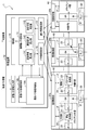
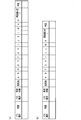
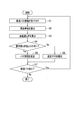
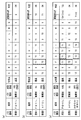
- FIG. 1 is a configuration diagram schematically illustrating a management device of a transmission system according to an embodiment of the present invention. It is a schematic diagram which shows the example of a structure of a relay node. 7A and 7B are schematic diagrams illustrating a storage structure of path information. (A)-(b) is a schematic diagram which shows the example of a setting of an effective band. 3 is a flowchart illustrating a flow of a process performed by the management device in FIG. 1. FIG. 3 is a schematic diagram illustrating a configuration example of a path. (A)-(c) is a schematic diagram which shows the example of calculation of delay fluctuation. FIG. 2 is a configuration diagram schematically illustrating a conventional transmission system that realizes an uninterrupted path. (A) to (d) are schematic diagrams of paths.
- the transmission system 1 shown in FIG. 1 is a network constituting a non-stop path, and transmits a client signal from a client (not shown).
- the transmission system 1 includes a management device 10 and a plurality of node devices 20 (20a, 20b, 20c, etc.) communicably connected to the management device 10.
- the transmission system 1 has a redundant path from a transmitting node (not shown) to a receiving node, and the same duplicated packet is transmitted through the redundant path.
- FIG. 1 illustrates the node devices 20a, 20b, and 20c.
- the node device 20a is, for example, a transmission node similar to the transmission node NE1 illustrated in FIG.
- the node device 20b is, for example, a relay node similar to the relay nodes NE11 to NE13 arranged on the short path in FIG.
- the node device 20c is, for example, a receiving node similar to the receiving node NE2 illustrated in FIG.
- one relay node (node device 20c) is illustrated for simplicity, but the number of relay nodes may be two or more.
- node devices 20 when the node devices 20a, 20b, and 20c are not distinguished, they are referred to as node devices 20.
- the node device 20 includes, for example, a switch SW, an interface board IF, and a CPU functioning as the monitoring control unit 40.
- the interface board IF IF board, line card
- the client IF board is provided at least at the end node devices 20a and 20b.
- the client IF board processes client signals input / output via the port 22, and includes a band control unit 21, a queue 23, a control IF 24, and the like.
- the band control unit 21 controls the band of the client signal so that the packet is transmitted within the network band set as permitted by the node device 20.
- the fluctuation absorption buffer delay time is set in the queue 23 (buffer) of the client IF board.
- the control IF 24 is an interface for transmitting and receiving signals between the IF board and the monitoring control unit 40.
- the relay IF boards are provided in all the node devices 20.
- the relay IF board includes a path header processing unit 25 for relaying between the node devices 20, a control IF 24, a queue 23, and the like.
- the path header processing unit 25 performs processing such as determining the identifier of the IF board to which the packet is output.
- In the interface board IF only one queue 23 is shown, but a queue divided for each priority may be provided.
- the monitoring control unit 40 monitors traffic information used as statistical information in the management device 10. Examples of such traffic information include a bandwidth used, a packet length, a priority, and the like for each relay node.
- the monitoring control unit 40 acquires information on the used band from, for example, the band control unit 21.
- the monitoring control unit 40 acquires the header information of the packet from, for example, the path header processing unit 25, and acquires the priority, the packet length, and the like described as the header information.
- the node device 20 includes, for example, a CPU, a memory such as a RAM and a ROM, and an NIC (Network Interface Card) for communication, and is a device including an optical cross connect, a router, a switch, and the like.
- a CPU central processing unit
- a memory such as a RAM and a ROM
- an NIC Network Interface Card
- FIG. 1 illustrates the node devices 20a, 20b, and 20c provided with three IF boards (line cards), but the configuration of the node device 20 is not limited to this.
- the node device 20d may include four IF boards (line cards).
- the node device 20d includes a switch SW and four IF boards.
- the number of node devices 20d is not particularly limited, a design using 15 relay nodes will be described below.
- the node devices 20d (hereinafter, referred to as nodes A to O) illustrated in FIG. 2 are, for example, relay nodes having the same configuration.
- the node device 20d includes a CPU that functions as the monitoring control unit 40 (see FIG. 1).
- FIG. 1 illustrates the node devices 20a, 20b, and 20c provided with three IF boards (line cards), but the configuration of the node device 20 is not limited to this.
- the node device 20d may include four IF boards (line cards).
- the node device 20d includes a switch SW and four
- the path of the path 1 is indicated by a dashed line as the path of the path to be set.
- the path of the path 1 is a path that passes through the nodes F, G, H, I, and J in this order.
- this route is simply referred to as FGHIJ.
- the management apparatus 10 of the transmission system 1 includes a new path information input unit 11, a new path information storage unit 12a, an existing path information storage unit 12b, a statistical information collection unit 13, a non-interruptible path design unit 14, An information setting unit 15 and a notification unit 16 are provided.
- the management device 10 is communicably connected to a terminal device operated by a user (operator) of the transmission system 1.
- the terminal device is, for example, a personal computer or the like, and a user can log in to the management device 10 from the terminal device and control the terminal device.
- the statistical information collection unit 13 collects statistical information of actual traffic from each node device 20.
- the statistical information of the actual traffic to be collected includes at least the used bandwidth and the packet length.
- the statistical information collecting unit 13 collects traffic information such as a used band, a packet length, and a priority for each node device 20.
- the statistical information collection unit 13 acquires the priority, the packet length, and the like from the monitoring control unit 40 of the node device 20.
- the statistical information collecting unit 13 outputs the statistical information collected from the node device 20 to the uninterrupted path design unit 14.
- the packet length may be the maximum packet length thus far or the average packet length.
- the new path information input unit 11 is a predetermined input interface or communication interface.
- the new path information input unit 11 receives, from a terminal device operated by a user of the transmission system 1, new path information including at least a path of a path and an accommodation band as path conditions, and stores the new path information in the new path information storage unit 12a.
- the accepted path information includes a path route, an accommodation band, a priority, a path type, and the like.
- the accommodation band is a band that can be accommodated in the link, and indicates a set value that is predetermined according to a path route or the like.
- the user writes the new path information to the new path information storage unit 12a via the new path information input unit 11 using a predetermined user interface such as a keyboard, a mouse, and a touch panel of the terminal device.
- the new path information storage unit 12a stores newly input path information. Thereafter, when new path information is received, the previous new path information storage unit 12a becomes a new existing path information storage unit 12b. When new path information is continuously received, a plurality of existing path information storage units 12b are provided, and identification information is assigned to each of them and managed. The new path information storage unit 12a is newly created each time new path information is received.
- the existing path information storage unit 12b stores existing path information already input before receiving the latest new path information, and has the same configuration as the new path information storage unit 12a.
- FIG. 3A shows an example of the storage structure of the path information stored in the path information storage unit 12.
- the path information storage unit 12 for example, as shown in FIG. 3A, the path identification, the route, the path type, the effective bandwidth, the priority, the fluctuation amount in the relay nodes A to O, the delay fluctuation T in the entire path, Information about each item of determination is stored.
- the path identification indicates a number or the like for identifying each path.
- the path identification includes information that distinguishes new path information from existing path information in addition to the number.
- the route is one piece of information of a path condition input as new path information. As described above, a delay fluctuation occurs due to collision of packets at a merging point when input packets from two different line cards are output from another line card. This route information is used to specify a collision location based on a route in line card units.
- the path type is one piece of information of the path condition input as new path information.
- the path type includes information for distinguishing between instantaneous interruption (failureless instantaneous interruption), planned instantaneous interruption, instantaneous interruption switching, and the like.
- the planned non-stop means that the short route is selected during normal operation and the non-stop is manually switched from the short route to the long route manually at the time of trouble transfer. Therefore, the planned uninterrupted interruption is also referred to as short-path uninterrupted interruption to be distinguished from the instantaneous interruption of failure.
- trouble transfer indicates that a route such as a user line is moved due to road construction or construction such as electricity, gas, and water supply.
- the effective band is band information calculated based on the actual traffic statistical information. The method of calculating the effective band will be described later. However, for a new path, a set value (set band) input as new path information is used as an effective band.
- the priority is one piece of path condition information input as new path information. The priority includes, for example, information for distinguishing the highest, normal, and the like.
- the amount of fluctuation in the relay nodes A to O means that collision occurs at a merging point when an input packet from a different IF board (line card) is output from one IF board (line card) in each node.
- the amount of fluctuation given from path n (n is an integer) to path m (m is an integer) is referred to as Tn.
- T1 indicates the amount of fluctuation given from path 1 to another path (path 2 or path 3).
- T2 indicates the amount of fluctuation given from path 2 to another path (path 1 or path 3).
- a to O are identifiers of the node device 20d shown in FIG. 2, and indicate locations where a fluctuation amount may occur.
- the delay fluctuation T is the total value of the fluctuation amount generated at the time of collision at each merging point in the entire path.
- the delay fluctuation T of the entire path for the path 1 is the fluctuation amount given to the own path (T1) from another path (path 2 or path 3) at the time of collision at the confluence point relating to path 1, and all of the fluctuation amounts for the collision point Shows the total value of the added fluctuation amount.
- the judgment indicates the result of judging whether or not the delay fluctuation T is smaller than the maximum fluctuation amount Tmax. For example, if the delay fluctuation T for the path 1 is smaller than the maximum fluctuation amount Tmax set in advance for the path 1 (T ⁇ Tmax), it is OK. If the delay fluctuation T is larger than the maximum fluctuation amount Tmax (T ⁇ Tmax), NG.
- the uninterrupted path design unit 14 calculates the delay fluctuation of the entire path with respect to the fluctuation of each section of the path based on the collected statistical information of the actual traffic every time the new path information is received, and calculates the calculated delay.
- a path whose fluctuation is smaller than the maximum fluctuation amount is designed as an uninterrupted path.
- the maximum fluctuation amount is a maximum value of the fluctuation absorption buffer amount predetermined according to the buffer amount in the receiving node.
- the uninterrupted path design unit 14 includes an effective band calculation unit 141, a delay fluctuation calculation unit 142, and a setting availability determination unit 143.
- the effective bandwidth calculation unit 141 calculates the effective bandwidth based on the utilization bandwidth that is the collected statistical information of the actual traffic.
- the effective bandwidth calculation unit 141 calculates an effective bandwidth for each existing path in consideration of the received new path.
- the effective bandwidth calculation unit 141 calculates the effective bandwidth based on the collected bandwidth, which is the statistical information of the actual traffic, as information for updating the accommodated bandwidth (set bandwidth) stored in the new path information storage unit 12a.
- the effective bandwidth calculation unit 141 can calculate the effective bandwidth by, for example, multiplying the maximum value of the utilization bandwidth, which is collected statistical information of the actual traffic, in a predetermined period by a safety coefficient.
- the calculation of the effective band performed by the effective band calculation unit 141 will be described with reference to FIG.
- the horizontal axis of the graph indicates time t, and the vertical axis indicates actual traffic.
- the unit of actual traffic is bps (bit @ per @ second).
- the set band is stored in the new path information storage unit 12a as an initial value of the effective band.
- the set bandwidth is, for example, 1 Gbps.
- the effective band is 0.4 Gbps, which is much smaller than the initially set band (1 Gbps).
- the effective bandwidth can be estimated by multiplying the maximum bandwidth of the statistical information of the actual traffic collected during the period from t1 to t2 by a predetermined safety coefficient.
- the effective band is 0.4 Gbps.
- the set bandwidth is merely set for any path regardless of the period. According to the present embodiment, since the effective band is set, the resources of the band can be used effectively.
- the longer the data collection period for calculating the effective bandwidth and the longer the data collection period as a whole the lower the probability that a traffic volume exceeding the maximum bandwidth occurs. That is, the accuracy of the effective bandwidth calculated for each data collection period for calculating the effective bandwidth increases. Therefore, as shown in FIG. 4B, the longer the collection period as a whole, the more the safety coefficient can be gradually reduced.
- the horizontal axis of the graph indicates time t
- the vertical axis indicates the effective band.
- a predetermined set band is stored in the new path information storage unit 12a as an initial value of the effective band.
- the effective band is calculated by multiplying the maximum band in the data collection period for calculating the effective band by the first safety coefficient.
- the effective band calculated at this time is greatly reduced as compared with the initially set band as shown in the figure.
- the effective band is calculated by multiplying the maximum band in the data collection period for calculating the effective band by a second safety coefficient slightly smaller than the first safety coefficient.
- the effective band calculated at this time is slightly smaller than the previous effective band as shown in the figure. Further, thereafter, the effective band is calculated by multiplying the maximum band in the data collection period for calculating the effective band by a third safety coefficient slightly smaller than the second safety coefficient. The effective band calculated at this time is slightly smaller than the previous effective band as shown in the figure.
- the safety coefficient can be similarly reduced. This makes it possible to increase the traffic accommodation efficiency.
- the delay fluctuation calculator 142 calculates delay fluctuations for a new path and an existing path.
- the delay fluctuation calculator 142 calculates, in the node device 20, the delay fluctuation that occurs at the merging point when an input packet from a different IF board (line card) is output from one IF board (line card).
- the delay fluctuation T of the entire path is calculated by summing the delay fluctuations occurring at the merging point.
- the delay fluctuation calculator 142 calculates the delay fluctuation occurring at each merging point using the statistical information of the actual traffic collected from each node device 20.
- the fluctuation (maximum delay fluctuation) that occurs when packets collide with each other at the maximum packet length at the merging point is calculated, and this is integrated for the collision point.
- the method of calculating the maximum fluctuation is not particularly limited.
- the fluctuation amount Tn given from the path n (n is an integer) to the path m (m is an integer) at the merging point may be calculated using the following equation (1).
- the maximum packet length indicates, for example, a maximum value within a predetermined period of a packet length collected as statistical information of actual traffic collected from the node device 20.
- the maximum transmission band length indicates, for example, the maximum value of a collected accommodation band within a predetermined period.
- the fluctuation amount T1 given from the path 1 to the path 3 is expressed by the following equation (2), and the fluctuation amount T3 given from the path 3 to the path 1 Is represented by the following equation (4).
- the sum of Tn for the collision location means that the number of background traffic inputs from different line cards is integrated.
- the delay fluctuation of the entire path 1 is the sum of the fluctuation amounts that the path 1 receives from other paths at the merging point.
- the delay fluctuation T of the entire path 1 is expressed by the following equation (6). Indicated by Here, T2 indicates the amount of fluctuation given from path 2 to path 1, and T3 indicates the amount of fluctuation given from path 3 to path 1.
- the setting availability determination unit 143 determines, for each of the new path and the existing path, whether or not the delay fluctuation T of the entire path is smaller than the maximum fluctuation amount Tmax determined for each path. When the delay fluctuation T of the entire path is smaller than the maximum fluctuation amount Tmax, the setting possibility determination unit 143 determines that the setting is possible, and designs the path as an uninterrupted path. At this time, the setting availability determination unit 143 notifies the path information setting unit 15 that a path in which the delay fluctuation T is smaller than the maximum fluctuation amount Tmax can be designed as an uninterrupted path (setting possible). When the delay fluctuation T of the entire path is equal to or larger than the maximum fluctuation amount Tmax, the setting possibility determination unit 143 determines that setting is not possible and notifies the notification unit 16 of that (setting failure).
- the path information setting unit 15 sets a path designed as a hitless path by the hitless path design unit 14 in each node device 20. That is, the path information setting unit 15 converts the effective bandwidth (path information) stored in the path information storage unit 12 for the path in which the delay fluctuation of the entire path is smaller than the maximum fluctuation amount, into the node device 20 configuring the path. Is set in the node device 20 as an allowable band.
- the path information setting unit 15 determines the non-instantaneous path in which the path information is stored in the existing path information storage unit 12b. Update path information.
- the path information updated here includes at least the accommodation band.
- the path information setting unit 15 updates the effective bandwidth recorded in the existing path information storage unit 12b based on the calculation result of the effective bandwidth calculation unit 141.
- the set value is used as it is as the effective band.
- the path information setting unit 15 updates the delay fluctuation T already stored in the existing path information storage unit 12b with the delay fluctuation T calculated for the existing path.
- the path information setting unit 15 stores the delay fluctuation T calculated for the new path in the new path information. It is stored in the unit 12a.
- the notifying unit 16 notifies the user of a path that has not been designed as an uninterrupted path by the uninterrupted path designing unit 14.
- the notification unit 16 transmits information of a path that cannot be set as an uninterrupted path among the path information received by the management apparatus 10 to a terminal device operated by a user of the transmission system 1.
- the notification unit 16 also transmits information on a path designed as a hitless path to the terminal device. By confirming the path information displayed on, for example, the liquid crystal display of the terminal device, the user can recognize whether or not the path under the desired path condition has been set as the uninterrupted path.
- the management device 10 includes, for example, an arithmetic device such as a CPU, a storage device such as a memory, and an interface device that transmits and receives various information to and from the outside.
- an arithmetic device such as a CPU
- a storage device such as a memory
- an interface device that transmits and receives various information to and from the outside.
- FIG. 5 is a flowchart showing a flow of processing by the management device of FIG.
- the management device 10 executes a step of collecting, from each node device 20, statistical information of actual traffic including at least the used bandwidth and the packet length.
- the management apparatus 10 receives the new path information including at least the path of the path and the accommodation band as the path condition by the new path information input unit 11 (step S1).
- the new path information input unit 11 stores the received new path information in the new path information storage unit 12a.
- the effective bandwidth calculation unit 141 calculates the effective bandwidth for each existing path based on the collected actual traffic statistical information, taking into account the new path received in step S1 ( Step S2).
- the path information setting unit 15 updates the effective band recorded in the existing path information storage unit 12b according to the calculation result of the effective band calculation unit 141.
- the set value is used as it is as the effective band.
- the delay fluctuation calculator 142 calculates the delay fluctuation of the entire path with respect to the fluctuation of each section of the path for the new path and the existing path (step S3).
- the path information setting unit 15 records the delay fluctuation calculated for the new path in the new path information storage unit 12a. Further, the path information setting unit 15 updates the delay fluctuation recorded in the existing path information storage unit 12b with the delay fluctuation calculated for the existing path.
- step S4 determines whether the calculated delay fluctuation is smaller than the maximum fluctuation amount determined for each path for the new path and the existing path (step S4).
- step S4: Yes when the delay fluctuation is smaller than the maximum fluctuation amount for the new path (step S4: Yes), the path information setting unit 15 sets the path information recorded in the new path information storage unit 12a to each node device. (Step S5).
- step S5 When the delay fluctuation of the existing path is smaller than the maximum fluctuation amount (step S4: Yes), the path information setting unit 15 designs the path as a non-instantaneous path and sets the existing path information storage unit as the non-instant path.
- the path information recorded in 12b is set in each node device 20 (step S5).
- step S4 when the delay fluctuation is equal to or more than the maximum fluctuation amount for the new path or the existing path (step S4: No), the path information setting unit 15 does not design the path as the path without instantaneous interruption. Instead, the notification unit 16 notifies that a path that has not been designed as a hitless path cannot be set (step S6). If a new path is input following step S5 or step S6 (step S7: Yes), the process returns to step S1, and if no new path is input (step S7: No), the process ends.
- FIG. 6 is a schematic diagram illustrating a configuration example of a path.
- the node device illustrated in FIG. 6 is similar to the node device 20d illustrated in FIG.
- FIG. 6 schematically illustrates paths of paths 2 and 3 in addition to the path of path 1 (dashed line) shown in FIG.
- the path of the path 2 is a path that passes through the nodes A, F, G, and L in this order. In the following, this path will be simply referred to as AFGL.
- the path of the path 3 is a path that passes through the nodes A, B, G, H, M, N, I, and J in this order. Hereinafter, this path is simply referred to as ABGHHMNIJ.
- both the path 1 and the path 2 pass through the node F. Therefore, in the node F, when a packet is output from an IF board (hereinafter, referred to as a line card), a delay fluctuation occurs at a merging point (a location shown by a broken-line circle in FIG. 6). In addition, as shown in FIG. 6, both the path 1 and the path 3 pass through the node G and the node I. For this reason, in the nodes G and I, when packets are output from the line card, delay fluctuation occurs at a merging point (a location indicated by a broken-line circle in FIG. 6).
- the design is performed by determining whether or not the delay fluctuation based on the set bandwidth is equal to or less than the maximum fluctuation amount under the same conditions for all the paths.
- FIG. 7 it will be described with reference to FIG. 7 (refer to FIG. 6 as appropriate) that the setting can be performed under the condition for each pass.
- FIG. 7A shows the path conditions of the path 1 shown in FIG. 6 as "FGHIJ", the path type is "uninterrupted", the set bandwidth is "10G”, and the priority is
- FIG. 7 is a diagram schematically illustrating a new path information storage unit 12a when new path information in which is “highest” is input. Since the identification number of the path 1 is “1” and is the new path information here, it is assumed that the path identification is “new 1”. Also, since the information is new path information, the set bandwidth (10 G (setting)) is stored in the effective bandwidth of path 1. Further, it is assumed that the amount of fluctuation at each of the nodes F, G, H, I, and J constituting the path route is T1.
- the delay fluctuation T is smaller than the maximum fluctuation amount Tmax of the path 1 (T ⁇ Tmax), so that the judgment item is OK (can be set as a path without any interruption).
- the data of the path type “existing 1” is the same as the data of the path type “new 1” in FIG. 7A.
- the description of the data of the path type “existing 1” will be described later.
- the data of the path type “new 2” schematically shows the new path information storage unit 12a storing the new path information of the path 2 shown in FIG.
- the path condition of the path 2 is that the path is “AFGL”, the path type is “uninterrupted”, the set bandwidth is “20G”, and the priority is “highest”.
- the identification number of the path 2 is “2”, which is new path information here, so the path identification is “new 2”.
- the set bandwidth (20 G (setting)) is stored in the effective bandwidth of the path 2.
- the amount of fluctuation in each of the nodes A, F, G, and L constituting the path route is T2.
- the delay fluctuation T in the entire path 2 is the fluctuation amount T1 given from another path (path 1) to the own path (path 2).
- the judgment item is OK (can be set as a non-interruptible path).
- the effective bandwidth is calculated by multiplying the maximum bandwidth of the statistical information of the actual traffic collected during the data collection period for calculating the effective bandwidth by a predetermined safety coefficient.
- the effective bandwidth is 5 Gbps, which is much smaller than the initially set bandwidth (10 Gbps).
- the delay fluctuation T in the entire path 1 is the fluctuation amount T2 given to the own path (path 1) from another path (path 2).
- the item of the judgment is OK (can be set as a path without an instantaneous interruption).
- the data of the path type “existing 2” is the same as the data of the path type “new 2” in FIG. 7 (b). This means that the new path information storage unit 12a storing the path information of the path 2 in the past becomes the existing path information storage unit 12b again.
- the data of the path type “existing 2” and the data of the path type “existing 1” will be described later.
- the data of the path type “new 3” schematically shows the new path information storage unit 12a storing the new path information of the path 3 shown in FIG.
- the path condition of the path 3 is as follows: the route is “ABGHHMNIJ”, the path type is “uninterrupted”, the set bandwidth is “30G”, and the priority is “highest”. There is.
- the identification number of the path 3 is “3”, which is the new path information here, so the path identification is “new 3”.
- the set bandwidth (30G (setting)) is stored in the effective bandwidth of the path 3. Further, it is assumed that the amount of fluctuation in each of the nodes A, B, G, H, M, N, I and J constituting the path route is T3.
- the delay fluctuation T in the entire path 3 is the integrated value (T1 ⁇ 2) of the collision amount with respect to the fluctuation amount T1 given from the other path (path 1) to the own path (path 3).
- the item of the determination is OK (can be set as a path without instantaneous interruption).
- the data of the path type “existing 2” has some information updated compared to the data of the path type “new 2” in FIG. 7 (b).
- the effective bandwidth is calculated by multiplying the maximum bandwidth of the statistical information of the actual traffic collected during the data collection period for calculating the effective bandwidth by a predetermined safety coefficient.
- the effective bandwidth is 8 Gbps [bps], which is much smaller than the initially set bandwidth (20 Gbps [bps]). Note that the delay fluctuation T of the entire path for the path 2 does not change, and the determination item is OK (can be set as a non-instantaneous interruption path).
- FIG. 7C some information of the data of the path type “existing 1” is updated compared to the data of the path type “existing 1” in FIG. 7B.
- the newly calculated effective bandwidth is 4.4 Gbps [bps], which is smaller than the previous effective bandwidth (5 Gbps [bps]).
- the collision also occurs at the merging point of the node G and the node I through which both the path 1 and the path 3 pass. appear.
- the delay fluctuation T in the entire path 1 is the fluctuation amount T2 applied from the other path (path 2) to the own path (path 1) and the fluctuation applied from the other path (path 3) to the own path (path 1). It is the sum of the integrated value (T3 ⁇ 2) for the collision location for the amount T3.
- the judgment item is NG (cannot be set as a path without any interruption).
- the management device of the present embodiment by performing flexible bandwidth design based on the effective bandwidth calculated from the statistical information of the actual traffic, it is possible to effectively use the bandwidth in the path without any interruption.
- the designer since the designer has set based on the worst value condition, it is difficult to design a flexible band, and the accommodation efficiency has been reduced.
- operability and traffic accommodation efficiency in a highly reliable network are improved.
- the delay fluctuation of the entire path only needs to be equal to or less than the maximum fluctuation amount only at the time of manual switching.
- a path with a small number of relay nodes that relays between a transmitting node and a receiving node or a path with a small number of interrupts in a relay node is traffic-free. Can be increased, or the number of relay nodes can be increased. Therefore, the reliability of the network can be further improved.
- the delay fluctuation calculating unit 142 has been described as calculating the delay fluctuation occurring at the merging point using the maximum packet length collected as statistical information, but is not limited thereto.
- the fluctuation may be calculated using the maximum packet length in design. For example, if the device can pass from 64 bytes to 9000 bytes including the jumbo frame, the maximum packet length in design is 9000 bytes.
- the packet length in the statistical information if only the packet length from 64 bytes to 1000 bytes passes, 1000 bytes can be used as the maximum packet length in collecting the statistical information (the packet used by the user).
- the length is 64 bytes to 1000 bytes).
- the fluctuation may be calculated using the average packet length on the statistical information instead of the maximum packet length. For example, in a network where a packet of 1000 bytes hardly comes, if the average packet length is 300 bytes, the accommodation efficiency can be further improved.
- the delay fluctuation calculating unit 142 has been described as calculating the delay fluctuation generated at the merging point using the maximum packet length and the maximum accommodating bandwidth collected as statistical information, together with the maximum packet length. Instead of the information maximum band, a design maximum band or statistical information average band may be used.
- the delay fluctuation calculating unit 142 may calculate the delay fluctuation occurring at the merging point using the collision occurrence probability based on the used bandwidth and the average packet length, which are collected statistical information of the actual traffic. Good.
- the method of calculating the collision occurrence probability is not particularly limited as long as it can be calculated.
- the fluctuation amount T'n given from the path n (n is an integer) to the path m (m is an integer) at the merging point may be calculated using the following equation (7).
- the average service time in the first term on the right side of the equation (8) indicates a time until an input packet is output when a packet is transferred at a predetermined rate. For example, when a packet is transferred at a rate of 100 Gbps, an average service time until a 1000-byte packet is input and output is 1000 ⁇ 8 ⁇ 10 -11 seconds or the like.
- the average packet length which is the numerator of the second term on the right side of the equation (8), indicates an average value within a predetermined period of the packet length collected as the statistical information of the actual traffic collected from the node device 20 at the merging point.
- 10 11 which is the denominator of the second term on the right side of Expression (8) indicates 10 11 [bps].
- the maximum bandwidth which is the denominator on the rightmost side of Expression (9) indicates the maximum accommodation bandwidth collected as statistical information. Instead of the maximum bandwidth on the statistical information, a maximum bandwidth on the design or an average bandwidth on the statistical information may be used.
- the sum of the effective bands as the numerator on the rightmost side of the equation (9) is the sum of the effective bands of the paths merging at the merging point. In the example of FIG. 7C, the sum is 4.4G + 8G + 30G.
- the delay fluctuation of the path n over the entire path is calculated.
- T the delay fluctuation T is expressed by the following equation (10).
- the sum of T'n for the collision location means that the sum of the number of background traffic inputs merging from different line cards is added.
- the notification unit 16 notifies the user that the path cannot be designed as an uninterrupted path under the path conditions received as path information from the outside (cannot be set).
- An optional function of notifying other information may be provided.
- other information for example, a maximum accommodable band can be cited. As a result, the user can recognize that the reason why the path to be designed as the uninterrupted path cannot be set is due to insufficient bandwidth.
- the management apparatus 10 searches for a path that does not become short on a path different from the path path input as the path condition.
- a function may be further provided.
- the notification unit 16 can include, for example, information on a recommended alternative route as other information to be notified by the optional function. This allows the user to set a hitless path when the recommended alternative path is accepted.
Landscapes
- Engineering & Computer Science (AREA)
- Computer Networks & Wireless Communication (AREA)
- Signal Processing (AREA)
- Data Exchanges In Wide-Area Networks (AREA)
Abstract
【課題】各パスの条件に応じた柔軟な帯域設計をすることのできる伝送システムの管理装置および伝送システムの設計方法を提供する。 【解決手段】伝送システム1の管理装置10は、新規パス情報入力部11と、各ノードから実トラヒックの統計情報を収集する統計情報収集部13と、新規パス情報を受け付けるたびに、収集された実トラヒックの統計情報に基づいて、パスの区間ごとの揺らぎに対しパス全体における遅延揺らぎを算出し、遅延揺らぎが受信ノードにおけるバッファ量に応じた最大揺らぎ量よりも小さいパスを無瞬断パスとして設計する無瞬断パス設計部14と、無瞬断パスについて、当該パスのパス情報を更新して既存パス情報格納部12bに格納すると共に、当該パスを構成するノードにおいて許容される帯域をノードに設定するパス情報設定部15と、無瞬断パスとして設計されなかったパスをユーザに報知する報知部16と、を備える。
Description
本発明は、伝送システムの管理装置および伝送システムの設計方法に係り、特に、無瞬断パスを構成する伝送システムの管理装置および伝送システムの設計方法に関する。
これまでに、100Gbit/s級の大容量光伝送と、IP系トラヒックの柔軟かつ効率的な収容を実現する技術が開発されてきている(非特許文献1、非特許文献2参照)。また、非特許文献1および非特許文献2には、LSP(Label Switched Path)が設定区間ごとに冗長構成をとることができ、障害発生時には50ms以下での高速切替えによる瞬断プロテクションを行うことができることが記載されている。また、非特許文献2には、パケットのオーバヘッドを用いて、運用系・予備系それぞれのパケットの遅延差を装置内部のバッファで吸収することにより、伝送路障害あるいは装置故障を契機に1パケットの欠落もなく切り替える無瞬断プロテクションを実現できることが紹介されている。無瞬断プロテクションによれば、通信サービスを中断させることなく、高い信頼性を担保することができる。さらに、特許文献1には、伝送経路故障時の遅延増加を抑えた無瞬断切替えを実現する先着優先型の無瞬断切替え技術が開示されている。このように、高信頼な通信が要求されるネットワークにおいては、無瞬断パスにより、障害時に無瞬断を実現する故障無瞬断技術や、手動切替え時に無瞬断を実現する計画無瞬断技術などが実現されている。
図8は、無瞬断パスを実現する従来の伝送システムを模式的に示す構成図である。
図8に示す伝送システム101は、例えば、送信ノードNE1、受信ノードNE2、中継ノードNE11~NE16および管理装置110を備えている。図8では、一部の図示を簡略化している。伝送システム101は、送信ノードNE1と受信ノードNE2との間には冗長経路を有する。図1では、送信ノードNE1から受信ノードNE2へ、複製された同一パケットが伝送されるものとして示しているが、反対向きの伝送も可能である。ここでは、ホップ数は例えば3である。中継ノードNE11~NE13は短経路を構成している。中継ノードNE14~NE16は長経路を構成している。各ノードは、CPU(Central Processing Unit)、スイッチSW、複数のインタフェース盤(以下、IF盤と称し、図面では単にIFと表記する)等を備えている。IF盤は、ラインカードとも呼ばれている。なお、バッファは、端点ノード(送信ノードNE1、受信ノードNE2)に設けられており、2つの端点ノードは図8において対称な構成要素を備えている。中継ノードは、端点ノードとは構成が異なる。中継ノードNE11~NE16のCPUおよびスイッチSWについては図示を省略している。長経路側の中継ノードの構成は、短経路側の中継ノードの構成と同じでも構わない。
図8に示す伝送システム101は、例えば、送信ノードNE1、受信ノードNE2、中継ノードNE11~NE16および管理装置110を備えている。図8では、一部の図示を簡略化している。伝送システム101は、送信ノードNE1と受信ノードNE2との間には冗長経路を有する。図1では、送信ノードNE1から受信ノードNE2へ、複製された同一パケットが伝送されるものとして示しているが、反対向きの伝送も可能である。ここでは、ホップ数は例えば3である。中継ノードNE11~NE13は短経路を構成している。中継ノードNE14~NE16は長経路を構成している。各ノードは、CPU(Central Processing Unit)、スイッチSW、複数のインタフェース盤(以下、IF盤と称し、図面では単にIFと表記する)等を備えている。IF盤は、ラインカードとも呼ばれている。なお、バッファは、端点ノード(送信ノードNE1、受信ノードNE2)に設けられており、2つの端点ノードは図8において対称な構成要素を備えている。中継ノードは、端点ノードとは構成が異なる。中継ノードNE11~NE16のCPUおよびスイッチSWについては図示を省略している。長経路側の中継ノードの構成は、短経路側の中継ノードの構成と同じでも構わない。
短経路の中継ノードNE11~NE13は、送信ノードNE1から受信ノードNE2へのトラヒック以外に、図中上方から別のトラヒックが割入れられるように構成されている。そのため、中継ノードNE11において、異なる2つのIF盤(ラインカード)からの入力パケットが別の1つのIF盤(ラインカード)から出力される際に合流ポイントで遅延揺らぎが発生する。同様に、中継ノードNE12,NE13においても、合流ポイントで遅延揺らぎがそれぞれ発生する。
そのため、伝送システム101の管理装置110は、送信ノードNE1から受信ノードNE2へ伝送されるパケットの短経路に対して遅延を挿入することによりタイミングを調整し、無瞬断切替えを実現している。短経路に遅延を挿入するとは、受信ノードNE2において、短経路を通るパス側に配備されたIF盤のバッファでの揺らぎ吸収バッファ量として、揺らぎ吸収バッファ遅延時間を設定することを意味する。
堀口真、外4名、「100Gパケットトランスポートシステム(100G-PTS)の実用化」、NTT技術ジャーナル、2014年10月、第26巻、第10号、p.54-57.
川崎岳、外3名、「100Gbit/s高速大容量パケットトランスポートシステムの実用化開発」、電子情報通信学会論文誌B、一般社団法人電子情報通信学会、2016年4月、第J99-B巻、第4号、p.275-282.
従来技術では、中継ノードNE11~NE13で変動する遅延揺らぎを保障できないため、伝送システム101の設計者は、揺らぎ吸収バッファ量の許容できる最大値(以下、最大揺らぎ量と呼ぶ)に基づき、ホップ数や、パスにおいてトラヒックを収容できる帯域(収容帯域)を設計していた(最悪値設計)。そのため、パスの収容帯域が低く制限されていた。
従来のホップ数と収容帯域の設計について図9を参照して説明する。図9(a)は、従来の無瞬断パスを実現する伝送システムの設計を説明するためのパスの模式図である。図9(a)において、一列に並んだ10個の正方形は、通信ネットワークにおいて無瞬断パスを構成可能なノードをそれぞれ示している。ここでは、ノードAは送信ノード、ノードJは受信ノード、ノードB~Iは中継ノードであるものとする。送信ノードから受信ノードへのパスの経路は、図において水平方向にすべての中継ノードを経由するものとしている。また、図において下方からの別トラヒックの割入れを考慮したときに、このネットワークへ設定可能な9本のパスが9本の矢印で示されている。
この例では、算出条件としては、ホップ数が「最大ホップ数」であり、すべての中継ノードが「割入れ有」であるものとする。すなわち、ホップ数が8であり、割入れ数が8であるものとしている。具体的には、8個の中継ノードB~Iに対して、図中下方から別のトラヒックがそれぞれ割入れられるように構成されている。これは、従来技術では、収容条件によらず中継ノード数固定、全ノードにおいてトラヒック割入れが発生すると仮定し、収容制限しているからである。この前提で、従来技術は、全パスについて同一条件で設定帯域901に基づいて遅延揺らぎが最大揺らぎ量以下となるように設計している。すなわち、従来技術は、すべてのパスに同一の算出条件で、設計者によって各パスに予め設定された帯域(設定帯域)を基にした最悪値設計を行っている。
図9(b)~図9(d)は、パスごとの条件で無瞬断パスを実現する伝送システムの設計を説明するためのパスの模式図である。図9(b)に示す9本のパスは、算出条件としては図9(a)に示すパスと同様に、ホップ数が8であり、割入れ数が8であるものとしている。ただし、この場合には、設定帯域を基にするのではなく、パスごとの条件として実トラヒックを反映した実効帯域902に基づいて遅延揺らぎが最大揺らぎ量以下となるように設計する。
図9(c)に示す3本のパスは、算出条件としては、ホップ数が2であり、割入れ数が2であるものとして、実効帯域903に基づいて遅延揺らぎが最大揺らぎ量以下となるように設計することを模式的に示している。なお、ここでは、ノードAは送信ノード、ノードDは受信ノード、ノードB、Cは中継ノードであるものとする。
図9(d)に示す4本のパスは、算出条件としては、ホップ数が8であり、割入れ数が3であるものとして、実効帯域904に基づいて遅延揺らぎが最大揺らぎ量以下となるように設計することを模式的に示している。なお、図9(b)~図9(d)において矢印の太さは収容帯域の大きさの違いを表している。
図9(c)に示す3本のパスは、算出条件としては、ホップ数が2であり、割入れ数が2であるものとして、実効帯域903に基づいて遅延揺らぎが最大揺らぎ量以下となるように設計することを模式的に示している。なお、ここでは、ノードAは送信ノード、ノードDは受信ノード、ノードB、Cは中継ノードであるものとする。
図9(d)に示す4本のパスは、算出条件としては、ホップ数が8であり、割入れ数が3であるものとして、実効帯域904に基づいて遅延揺らぎが最大揺らぎ量以下となるように設計することを模式的に示している。なお、図9(b)~図9(d)において矢印の太さは収容帯域の大きさの違いを表している。
従来技術では、無瞬断パスに対して、図9(b)~図9(d)に示すようなパスごとの条件で柔軟に伝送システムを設計することができなかった。一方、高信頼ネットワークにおける運用性と収容効率の観点からは、全パス同一条件で設計する代わりに、パスごとの条件で設計することが望まれている。
そこで、本発明では、前記した問題を解決し、各パスの条件に応じた柔軟な帯域設計をすることのできる伝送システムの管理装置および伝送システムの設計方法を提供することを課題とする。
前記した課題を解決するため、請求項1に係る発明は、送信ノードと受信ノードとの間に中継ノードからなる冗長経路を有する伝送システムの管理装置であって、パス条件として少なくともパスの経路および収容帯域を含む新規パス情報を受け付けて新規パス情報格納部に格納する新規パス情報入力部と、各ノードから少なくとも利用帯域およびパケット長を含む実トラヒックの統計情報を収集する統計情報収集部と、前記新規パス情報を受け付けるたびに、前記収集された実トラヒックの統計情報に基づいて、パスの区間ごとの揺らぎに対しパス全体における遅延揺らぎを算出し、算出された遅延揺らぎが前記受信ノードにおけるバッファ量に応じた最大揺らぎ量よりも小さいパスを無瞬断パスとして設計する無瞬断パス設計部と、前記無瞬断パスとして設計されたパスについて、当該パスの収容帯域を少なくとも含むパス情報を更新して既存パス情報格納部に格納すると共に、当該パスを構成するノードにおいて許容される帯域をパス情報として前記ノードに設定するパス情報設定部と、前記無瞬断パスとして設計されなかったパスをユーザに報知する報知部と、を備える伝送システムの管理装置である。
また、前記した課題を解決するため、請求項6に係る発明は、送信ノードと受信ノードとの間に中継ノードからなる冗長経路を有する伝送システムの管理装置による伝送システムの設計方法であって、前記管理装置が、各ノードから少なくとも利用帯域およびパケット長を含む実トラヒックの統計情報を収集する工程と、パス条件として少なくともパスの経路および収容帯域を含む新規パス情報を受け付けて新規パス情報格納部に格納する工程と、前記新規パス情報を受け付けるたびに、前記収集された実トラヒックの統計情報に基づいて、パスの区間ごとの揺らぎに対しパス全体における遅延揺らぎを算出し、算出された遅延揺らぎが前記受信ノードにおけるバッファ量に応じた最大揺らぎ量よりも小さいパスを無瞬断パスとして設計する工程と、前記無瞬断パスとして設計されたパスについて、当該パスの収容帯域を少なくとも含むパス情報を更新して既存パス情報格納部に格納すると共に、当該パスを構成するノードにおいて許容される帯域をパス情報として前記ノードに設定する工程と、前記無瞬断パスとして設計されなかったパスをユーザに報知する工程と、を含む伝送システムの設計方法である。
このようにすることで、伝送システムの管理装置は、各ノードから利用帯域およびパケット長を含む実トラヒックの統計情報を収集する。そして、管理装置は、実トラヒックの統計情報に基づいて算出した遅延揺らぎが最大揺らぎ量よりも小さいパスを無瞬断パスとして設定し、設定できなかったパスについてはユーザに報知することができる。よって、伝送システムにおいて各パスの条件に応じた柔軟な帯域設計をすることが可能となる。
また、請求項2に係る発明は、前記無瞬断パス設計部が、前記新規パス情報格納部に格納された収容帯域を更新する情報として、前記収集された実トラヒックの統計情報である利用帯域に基づいて実効帯域を算出する実効帯域算出部と、前記ノードにおいて、異なるラインカードからの入力パケットが1つのラインカードから出力される際に合流ポイントで発生する遅延揺らぎを算出し、各合流ポイントで発生する遅延揺らぎを合計することで前記パス全体の遅延揺らぎを算出する遅延揺らぎ算出部と、前記パス全体の遅延揺らぎを前記最大揺らぎ量より小さいか否かを判別し、前記パス全体の遅延揺らぎが前記最大揺らぎ量より小さい場合、設定可能と判定して前記無瞬断パスとして設計し、前記パス全体の遅延揺らぎが前記最大揺らぎ量以上である場合、設定不可と判定して前記報知部に通知する設定可否判定部と、を備える請求項1に記載の伝送システムの管理装置である。
このようにすることで、伝送システムの管理装置は、実トラヒックの統計情報に基づいて実効帯域および遅延揺らぎを更新可能に算出することができる。
また、請求項3に係る発明は、前記遅延揺らぎ算出部が、前記合流ポイントにおいてパケット同士が最大パケット長で衝突する場合に発生する最大遅延揺らぎを算出することで、前記パス全体の遅延揺らぎを算出する請求項2に記載の伝送システムの管理装置である。
このようにすることで、伝送システムの管理装置は、遅延揺らぎの最大値を見積もって最大揺らぎ量と比較できるので、充分な余裕を持って大小判定を確実に行うことができる。
また、請求項4に係る発明は、前記遅延揺らぎ算出部が、前記収集された実トラヒックの統計情報である利用帯域および平均パケット長に基づく衝突発生確率を用いて前記合流ポイントで発生する遅延揺らぎを算出することで、前記パス全体の遅延揺らぎを算出する請求項2に記載の伝送システムの管理装置である。
このようにすることで、伝送システムの管理装置は、利用帯域および平均パケット長に基づく衝突発生確率を用いて遅延揺らぎを見積もるので、高精度に算出された遅延揺らぎを最大揺らぎ量と比較することができる。
また、請求項5に係る発明は、前記実効帯域算出部が、前記収集された実トラヒックの統計情報である利用帯域の所定期間における最大値に対して安全係数を掛けることで前記実効帯域を算出する請求項2から請求項4のいずれか一項に記載の伝送システムの管理装置である。
このようにすることで、伝送システムの管理装置は、充分な余裕を持って実効帯域を見積もることができるので、信頼性を高めることができる。
本発明によれば、伝送システムにおいて各パスの条件に応じた柔軟な帯域設計をすることができる。
以下、本発明の伝送システムの管理装置について図面を参照して詳細に説明する。
図1に示す伝送システム1は、無瞬断パスを構成するネットワークであり、図示しないクライアントからのクライアント信号を伝送するものである。伝送システム1は、管理装置10と、当該管理装置10と通信可能に接続された複数のノード装置20(20a,20b,20c等)と、を備えている。
図1に示す伝送システム1は、無瞬断パスを構成するネットワークであり、図示しないクライアントからのクライアント信号を伝送するものである。伝送システム1は、管理装置10と、当該管理装置10と通信可能に接続された複数のノード装置20(20a,20b,20c等)と、を備えている。
伝送システム1は、図示しない送信ノードから受信ノードへの冗長経路を有し、冗長経路には、複製された同一パケットが伝送される。図1には、ノード装置20a,20b,20cを図示している。ノード装置20aは、例えば、図8に示した送信ノードNE1と同様の送信ノードである。ノード装置20bは、例えば、図8において短経路に配置された中継ノードNE11~NE13と同様の中継ノードである。ノード装置20cは、例えば、図8に示した受信ノードNE2と同様の受信ノードである。ここでは、簡単のため1台の中継ノード(ノード装置20c)を図示しているが、中継ノードは2個以上であってもよい。以下では、ノード装置20a,20b,20cを区別しない場合、ノード装置20と表記する。
ノード装置20は、例えばスイッチSWと、インタフェース盤IFと、監視制御部40として機能するCPUと、を備えている。インタフェース盤IF(IF盤、ラインカード)は、例えばクライアントIF盤や中継IF盤として構成されている。
クライアントIF盤は、少なくとも端点のノード装置20a,20bに設けられている。クライアントIF盤は、ポート22を介して入出力するクライアント信号を処理するものであり、帯域制御部21、キュー23、制御IF24等を備える。帯域制御部21は、ノード装置20において許容するものとして設定されたネットワーク帯域内でパケットの送信を行うように、クライアント信号を帯域制御するものである。クライアントIF盤のキュー23(バッファ)には、揺らぎ吸収バッファ遅延時間が設定される。制御IF24は、IF盤と監視制御部40との間で信号の送受信を行うインタフェースである。
中継IF盤は、すべてのノード装置20に設けられている。中継IF盤は、ノード装置20間を中継するためのパスヘッダ処理部25、制御IF24、キュー23等を備える。パスヘッダ処理部25は、パケットを出力する先のIF盤の識別子を判定する等の処理を実行する。なお、インタフェース盤IFにおいて、キュー23は1つだけ図示されているが、優先度ごとに分けられたキューを備えるようにしてもよい。
クライアントIF盤は、少なくとも端点のノード装置20a,20bに設けられている。クライアントIF盤は、ポート22を介して入出力するクライアント信号を処理するものであり、帯域制御部21、キュー23、制御IF24等を備える。帯域制御部21は、ノード装置20において許容するものとして設定されたネットワーク帯域内でパケットの送信を行うように、クライアント信号を帯域制御するものである。クライアントIF盤のキュー23(バッファ)には、揺らぎ吸収バッファ遅延時間が設定される。制御IF24は、IF盤と監視制御部40との間で信号の送受信を行うインタフェースである。
中継IF盤は、すべてのノード装置20に設けられている。中継IF盤は、ノード装置20間を中継するためのパスヘッダ処理部25、制御IF24、キュー23等を備える。パスヘッダ処理部25は、パケットを出力する先のIF盤の識別子を判定する等の処理を実行する。なお、インタフェース盤IFにおいて、キュー23は1つだけ図示されているが、優先度ごとに分けられたキューを備えるようにしてもよい。
監視制御部40は、管理装置10において統計情報として利用されるトラヒック情報を監視するものである。このようなトラヒック情報としては、中継ノードごとの利用帯域、パケット長、優先度等を挙げることができる。監視制御部40は、例えば帯域制御部21から利用帯域の情報を取得する。監視制御部40は、例えばパスヘッダ処理部25からパケットのヘッダ情報を取得して、ヘッダ情報として記載された優先度やパケット長等を取得する。
ノード装置20は、例えば、CPUと、RAMやROM等のメモリと、通信を行うためのNIC(Network Interface Card)等を備え、光クロスコネクト、ルータ、スイッチ等からなる装置である。
図1には、3個のIF盤(ラインカード)を備えたノード装置20a,20b,20cを図示したが、ノード装置20の構成はこれに限定されない。例えば、図2に示すように、4個のIF盤(ラインカード)を備えたノード装置20dであってもよい。ノード装置20dは、スイッチSWと、4個のIF盤と、を備えている。ノード装置20dの個数は、特に限定されないが、以下では15個の中継ノードによる設計を説明する。図2に示すノード装置20d(以下、ノードA~ノードOという)は、例えば同じ構成を持った中継ノードである。図2では省略したが、ノード装置20dは、監視制御部40(図1参照)として機能するCPUを備えている。また、図2には、設定されるパスの経路として、パス1の経路が一点鎖線で示されている。パス1の経路は、ノードF、ノードG、ノードH、ノードI、ノードJをこの順序で経由する経路である。この経路を、以下では、単に、F-G-H-I-Jと表記する。
図1に戻って、伝送システム1の構成の説明を続ける。
伝送システム1の管理装置10は、新規パス情報入力部11と、新規パス情報格納部12aと、既存パス情報格納部12bと、統計情報収集部13と、無瞬断パス設計部14と、パス情報設定部15と、報知部16と、を備えている。なお、管理装置10は、伝送システム1のユーザ(オペレータ)が操作する端末装置と通信可能に接続されている。この端末装置は例えばパーソナルコンピュータ等であり、ユーザは端末装置から管理装置10にログインして制御することができる。
伝送システム1の管理装置10は、新規パス情報入力部11と、新規パス情報格納部12aと、既存パス情報格納部12bと、統計情報収集部13と、無瞬断パス設計部14と、パス情報設定部15と、報知部16と、を備えている。なお、管理装置10は、伝送システム1のユーザ(オペレータ)が操作する端末装置と通信可能に接続されている。この端末装置は例えばパーソナルコンピュータ等であり、ユーザは端末装置から管理装置10にログインして制御することができる。
統計情報収集部13は、各ノード装置20から、実トラヒックの統計情報を収集するものである。収集する実トラヒックの統計情報には、少なくとも利用帯域およびパケット長を含む。本実施形態では、統計情報収集部13は、ノード装置20ごとの利用帯域、パケット長、優先度等のトラヒック情報を収集する。統計情報収集部13は、ノード装置20の監視制御部40から、優先度やパケット長等を取得する。統計情報収集部13は、ノード装置20から収集した統計情報を無瞬断パス設計部14に出力する。
パケット長としては、これまでにきた最大パケット長としてもよいし、平均パケット長としてもよい。
パケット長としては、これまでにきた最大パケット長としてもよいし、平均パケット長としてもよい。
新規パス情報入力部11は、所定の入力インタフェースや通信インタフェースである。新規パス情報入力部11は、伝送システム1のユーザが操作する端末装置から、パス条件として少なくともパスの経路および収容帯域を含む新規パス情報を受け付けて新規パス情報格納部12aに格納する。受け付けるパス情報は、パス経路、収容帯域、優先度、パス種別等を含む。ここで、収容帯域は、リンクに収容できる帯域であって、パス経路等に応じて予め定められた設定値を示す。ユーザは、端末装置の例えばキーボード、マウス、タッチパネル等の所定のユーザインタフェースを用いて新規パス情報を、新規パス情報入力部11を介して、新規パス情報格納部12aに書き込む。
新規パス情報格納部12aは、新規に入力されたパス情報を格納するものである。その後に新規パス情報を受け付けた場合、以前の新規パス情報格納部12aは、新たに既存パス情報格納部12bとなる。また、新規パス情報を続けて受け付ける場合、既存パス情報格納部12bは複数設けられることになり、それぞれに識別情報が付与されて管理される。
新規パス情報格納部12aは、新規パス情報を受け付けるたびに新たに作成される。
既存パス情報格納部12bは、最新の新規パス情報を受け付ける前に既に入力された既存パス情報を記憶するものであり、新規パス情報格納部12aと同様な構成である。
新規パス情報格納部12aは、新規パス情報を受け付けるたびに新たに作成される。
既存パス情報格納部12bは、最新の新規パス情報を受け付ける前に既に入力された既存パス情報を記憶するものであり、新規パス情報格納部12aと同様な構成である。
以下では、新規パス情報格納部12aと既存パス情報格納部12bとを区別しない場合、単にパス情報格納部12と表記する。パス情報格納部12に記憶されるパス情報の記憶構造の一例を図3(a)に示す。パス情報格納部12には、例えば図3(a)に示すように、パス識別、経路、パス種別、実効帯域、優先度、中継ノードA~Oにおける揺らぎ量、パス全体での遅延揺らぎT、判定の各項目に関する情報が記憶される。
図3(a)において、パス識別は、各パスを識別するためのナンバー等を示す。この例では、パス識別は、ナンバー以外に新規パス情報と既存パス情報とを区別する情報を含む。
経路とは、新規パス情報として入力されるパス条件の1つの情報である。前記したように、異なる2つのラインカードからの入力パケットが別のラインカードから出力される際の合流ポイントではパケット同士の衝突によって遅延揺らぎが発生する。この経路情報は、ラインカード単位の経路を基にした衝突箇所の特定に利用される。
経路とは、新規パス情報として入力されるパス条件の1つの情報である。前記したように、異なる2つのラインカードからの入力パケットが別のラインカードから出力される際の合流ポイントではパケット同士の衝突によって遅延揺らぎが発生する。この経路情報は、ラインカード単位の経路を基にした衝突箇所の特定に利用される。
図3(a)において、パス種別とは、新規パス情報として入力されるパス条件の1つの情報である。パス種別は、無瞬断(故障無瞬断)、計画無瞬断、瞬断切替等を区別する情報を含む。ここで、計画無瞬断とは、通常運用時は短経路を選択し、支障移転時に計画的に短経路から長経路へと手動で無瞬断切替を行うことである。よって、計画無瞬断は、故障瞬断と区別して短経路無瞬断ともいう。なお、支障移転は、道路工事や電気・ガス・水道などの工事のため、ユーザ回線等の経路が移転されることを示す。
図3(a)において、実効帯域とは、実トラヒックの統計情報に基づき算出される帯域の情報である。なお、実効帯域の算出方法については後記する。ただし、新規パスについては、実効帯域として、新規パス情報として入力される設定値(設定帯域)が利用される。
優先度とは、新規パス情報として入力されるパス条件の1つの情報である。優先度は、例えば、最高、普通等を区別する情報を含む。
優先度とは、新規パス情報として入力されるパス条件の1つの情報である。優先度は、例えば、最高、普通等を区別する情報を含む。
また、中継ノードA~Oにおける揺らぎ量とは、各ノードにおいて、異なるIF盤(ラインカード)からの入力パケットが1つのIF盤(ラインカード)から出力される際に合流ポイントで衝突が発生するときに自パスから他パスへ与える揺らぎ量を示す。以下では、パスn(nは整数)からパスm(mは整数)へ与える揺らぎ量をTnと表記する。例えばT1は、パス1から他のパス(パス2やパス3)へ与える揺らぎ量を示す。また、T2は、パス2から他のパス(パス1やパス3)へ与える揺らぎ量を示す。図3(a)において、A~Oは、図2に示すノード装置20dの識別子であって、揺らぎ量が発生する可能性がある箇所を示す。後記する具体的な説明では、図2に示す15台のノード装置20dのうち、C~E、KおよびOの5台のノード装置20dを経由しないパスで説明する。そのため、後記する具体例の説明においては、図3(a)の記憶構造の代わりに、図3(b)に示すようにノード識別子の一部(C~E、KおよびO)を省略した簡易的な記憶構造を用いて説明する。
図3(a)において、遅延揺らぎTとは、各合流ポイントで衝突時に発生する揺らぎ量のパス全体での合計値である。例えばパス1についてのパス全体での遅延揺らぎTとは、パス1に関する合流ポイントにおいて衝突時に他のパス(パス2やパス3)から自パス(T1)へ与えられる揺らぎ量を、衝突箇所に関してすべて加算した揺らぎ量の総計値を示す。
図3(a)において、判定とは、遅延揺らぎTが最大揺らぎ量Tmaxより小さいか否かを判定した結果を示す。例えばパス1についての遅延揺らぎTが、パス1について予め設定された最大揺らぎ量Tmaxより小さい場合(T<Tmax)はOK、遅延揺らぎTが最大揺らぎ量Tmax以上である場合(T≧Tmax)はNGとする。
無瞬断パス設計部14は、新規パス情報を受け付けるたびに、収集された実トラヒックの統計情報に基づいて、パスの区間ごとの揺らぎに対しパス全体における遅延揺らぎを算出し、算出された遅延揺らぎが最大揺らぎ量よりも小さいパスを無瞬断パスとして設計するものである。ここで、最大揺らぎ量は、受信ノードにおけるバッファ量に応じて予め定められた揺らぎ吸収バッファ量の最大値である。
無瞬断パス設計部14は、実効帯域算出部141と、遅延揺らぎ算出部142と、設定可否判定部143と、を備えている。
実効帯域算出部141は、収集された実トラヒックの統計情報である利用帯域に基づいて実効帯域を算出するものである。実効帯域算出部141は、受け付けた新規パスを考慮して、各既存パスについて実効帯域をそれぞれ算出する。実効帯域算出部141は、新規パス情報格納部12aに格納された収容帯域(設定帯域)を更新する情報として、収集された実トラヒックの統計情報である利用帯域に基づいて実効帯域を算出する。
実効帯域算出部141は、例えば、収集された実トラヒックの統計情報である利用帯域の所定期間における最大値に対して安全係数を掛けることで実効帯域を算出することができる。実効帯域算出部141が行う実効帯域の算出について図4(a)を参照して説明する。図4(a)において、グラフの横軸は時間tを示し、縦軸は実トラヒックを示す。実トラヒックの単位はbps(bit per second)である。この例では、新規パスが設定された当初には、実効帯域の初期値として設定帯域が新規パス情報格納部12aに格納される。ここでは、設定帯域が例えば、1G[bps]である。前記所定期間である実効帯域算出用のデータ収集期間としては、例えば時刻t=0を開始時刻、時刻t=t1を終了時刻としてもよい。この場合、時刻t=0~時刻t=t1の期間に収集された実トラヒックの統計情報の最大帯域に対し、所定の安全係数を掛けることで実効帯域を見積もることができる。この例では、実効帯域が0.4G[bps]であり、当初の設定帯域(1G[bps])よりも大きく減少している。
また、例えば時刻t=t1、時刻t=t2を、それぞれ、実効帯域算出用のデータ収集期間の開始時刻および終了時刻としてもよい。この場合、t1~t2の期間に収集された実トラヒックの統計情報の最大帯域に対し、所定の安全係数を掛けることで実効帯域を見積もることができる。この例では、実効帯域が0.4G[bps]である。
従来技術では、実トラヒックの統計情報を考慮していなかったので、どのパスにも期間に関わらず設定帯域が設定されるのみであった。本実施形態によれば、実効帯域を設定するので、帯域の資源を有効に利用することができる。
従来技術では、実トラヒックの統計情報を考慮していなかったので、どのパスにも期間に関わらず設定帯域が設定されるのみであった。本実施形態によれば、実効帯域を設定するので、帯域の資源を有効に利用することができる。
また、この実トラヒックの統計情報については、実効帯域算出用のデータ収集期間を繰り返して全体としてのデータ収集期間を長くすればするほど、最大帯域を超えるトラヒック量が発生する確率は減少する。すなわち、実効帯域算出用のデータ収集期間ごとに算出した実効帯域の確度が高まってくる。そのため、図4(b)に示すように、全体としての収集期間が長くなるほど、徐々に安全係数を低減することができる。
図4(b)において、グラフの横軸は時間tを示し、縦軸は実効帯域を示している。図4(b)に示すように、新規パスが設定された当初(時刻t=0)には、所定の設定帯域が実効帯域の初期値として新規パス情報格納部12aに格納される。その後、実効帯域算出用のデータ収集期間における最大帯域に、第1の安全係数を掛けることで、実効帯域が算出される。このときに算出される実効帯域は、図示するように当初の設定帯域よりも大きく減少している。その後、実効帯域算出用のデータ収集期間における最大帯域に、第1の安全係数よりも僅かに小さな第2の安全係数を掛けることで、実効帯域が算出される。このときに算出される実効帯域は、図示するように前回の実効帯域よりも僅かに減少している。さらに、その後、実効帯域算出用のデータ収集期間における最大帯域に、第2の安全係数よりも僅かに小さな第3の安全係数を掛けることで、実効帯域が算出される。このときに算出される実効帯域は、図示するように前回の実効帯域よりも僅かに減少している。以下、同様に安全係数を小さくすることができる。これにより、トラフィックの収容効率を上げることが可能である。
遅延揺らぎ算出部142は、新規パスおよび既存パスについて遅延揺らぎを算出するものである。遅延揺らぎ算出部142は、ノード装置20において、異なるIF盤(ラインカード)からの入力パケットが1つのIF盤(ラインカード)から出力される際に合流ポイントで発生する遅延揺らぎを算出し、各合流ポイントで発生する遅延揺らぎを合計することでパス全体の遅延揺らぎTを算出する。
遅延揺らぎ算出部142は、各ノード装置20から収集した実トラヒックの統計情報を用いて、各合流ポイントで発生する遅延揺らぎを算出する。本実施形態では、例えば合流ポイントにおいてパケット同士が最大パケット長で衝突する場合に発生する揺らぎ(最大遅延揺らぎ)を算出し、これを衝突箇所について積算することとする。最大遅延揺らぎを算出することができれば、それを算出する方法は特に限定されない。一例として、合流ポイントにおいてパスn(nは整数)からパスm(mは整数)へ与える揺らぎ量Tnは、下記の式(1)を用いて算出することとしてもよい。

式(1)において、最大パケット長とは、例えば、ノード装置20から収集した実トラヒックの統計情報として収集されたパケット長に関して所定期間内の最大値を示す。また、最大伝送帯域長とは、例えば、収集された収容帯域に関して所定期間内の最大値を示す。
例えばパス1とパス2とが合流ポイントで衝突するときに、パス1からパス2へ与える揺らぎ量T1は、下記の式(2)で示され、パス2からパス1へ与える揺らぎ量T2は、下記の式(3)で示される。
また、例えばパス1とパス3とが合流ポイントで衝突するときに、パス1からパス3へ与える揺らぎ量T1は、下記の式(2)で示され、パス3からパス1へ与える揺らぎ量T3は、下記の式(4)で示される。
例えばパス1とパス2とが合流ポイントで衝突するときに、パス1からパス2へ与える揺らぎ量T1は、下記の式(2)で示され、パス2からパス1へ与える揺らぎ量T2は、下記の式(3)で示される。
また、例えばパス1とパス3とが合流ポイントで衝突するときに、パス1からパス3へ与える揺らぎ量T1は、下記の式(2)で示され、パス3からパス1へ与える揺らぎ量T3は、下記の式(4)で示される。

また、前記式(1)等を用いる最大遅延揺らぎを算出する方法において式(1)のTnを合流ポイントで発生する遅延揺らぎとして用いたとき、パスnについてのパス全体での遅延揺らぎをTとすると、この遅延揺らぎTは下記の式(5)で示される。

式(5)において、衝突箇所についてのTnの和は、別ラインカードから合流する背景トラヒックの入力の個数だけ積算することを意味する。例えばパス1の全体の遅延揺らぎとは、パス1が合流ポイントで他のパスから受ける揺らぎ量の積算となる。具体的には、パス1とパス2とが1箇所で合流し、かつ、パス1とパス3とが2箇所で合流する場合、パス1の全体の遅延揺らぎTは、下記の式(6)で示される。なお、T2はパス2からパス1へ与える揺らぎ量を示し、T3はパス3からパス1へ与える揺らぎ量を示す。

設定可否判定部143は、新規パスおよび既存パスそれぞれについて、パス全体の遅延揺らぎTが、パスごとに定められる最大揺らぎ量Tmaxより小さいか否かを判別するものである。設定可否判定部143は、パス全体の遅延揺らぎTが最大揺らぎ量Tmaxより小さい場合、設定可能と判定して無瞬断パスとして設計する。このとき、設定可否判定部143は、遅延揺らぎTが最大揺らぎ量Tmaxよりも小さなパスが無瞬断パスとして設計可能であること(設定可)をパス情報設定部15に通知する。設定可否判定部143は、パス全体の遅延揺らぎTが最大揺らぎ量Tmax以上である場合、設定不可と判定してその旨(設定不可)を報知部16に通知する。
パス情報設定部15は、無瞬断パス設計部14によって無瞬断パスとして設計されたパスを各ノード装置20に設定するものである。すなわち、パス情報設定部15は、パス全体についての遅延揺らぎが最大揺らぎ量より小さいパスについて、パス情報格納部12に格納されている実効帯域(パス情報)を、当該パスを構成するノード装置20において許容される帯域として、当該ノード装置20に設定する。
パス情報設定部15は、無瞬断パス設計部14から無瞬断パスとして設定可の通知を受けると、既存パス情報格納部12bにパス情報が格納された無瞬断パスについて、当該パスのパス情報を更新する。ここで更新されるパス情報は、少なくとも収容帯域を含んでいる。具体的には、パス情報設定部15は、実効帯域算出部141の算出結果によって、既存パス情報格納部12bに記録されている実効帯域を更新する。なお、新規パスの実効帯域については、設定値をそのまま実効帯域として用いる。また、パス情報設定部15は、既存パスについて算出された遅延揺らぎTによって、既存パス情報格納部12bに既に格納されている遅延揺らぎTを更新する。
パス情報設定部15は、新規パス情報格納部12aにパス情報としてパス条件が格納された新規パスについて、無瞬断パスとして設計するときには、新規パスについて算出された遅延揺らぎTを新規パス情報格納部12aに格納する。
報知部16は、無瞬断パス設計部14により無瞬断パスとして設計されなかったパスをユーザに報知するものである。報知部16は、管理装置10が入力を受け付けたパス情報のうち、無瞬断パスとして設定不可となったパスの情報を、伝送システム1のユーザが操作する端末装置へ送信する。また、報知部16は、無瞬断パスとして設計されたパスの情報も端末装置へ送信する。ユーザは、端末装置の例えば液晶ディスプレイ等に表示されるパスの情報を確認することにより、所望のパス条件のパスが、無瞬断パスとして設定できたか否かを認識することができる。
なお、管理装置10は、例えば、CPU等の演算装置と、メモリ等の記憶装置と、外部との間で各種情報の送受信を行うインタフェース装置とを備えている。
[管理装置による動作]
管理装置10による動作について図5を参照(適宜図1参照)して説明する。図5は、図1の管理装置による処理の流れを示すフローチャートである。
管理装置10は、各ノード装置20から少なくとも利用帯域およびパケット長を含む実トラヒックの統計情報を収集する工程を実行する。
上記前提のもと、管理装置10は、新規パス情報入力部11によって、パス条件として少なくともパスの経路および収容帯域を含む新規パス情報を受け付ける(ステップS1)。新規パス情報入力部11は、受け付けた新規パス情報を、新規パス情報格納部12aに格納する。
管理装置10による動作について図5を参照(適宜図1参照)して説明する。図5は、図1の管理装置による処理の流れを示すフローチャートである。
管理装置10は、各ノード装置20から少なくとも利用帯域およびパケット長を含む実トラヒックの統計情報を収集する工程を実行する。
上記前提のもと、管理装置10は、新規パス情報入力部11によって、パス条件として少なくともパスの経路および収容帯域を含む新規パス情報を受け付ける(ステップS1)。新規パス情報入力部11は、受け付けた新規パス情報を、新規パス情報格納部12aに格納する。
新規パス情報を受け付けるたびに、実効帯域算出部141は、ステップS1で受け付けた新規パスを考慮して、収集された実トラヒックの統計情報に基づいて、各既存パスについて実効帯域をそれぞれ算出する(ステップS2)。このとき、パス情報設定部15は、実効帯域算出部141の算出結果によって、既存パス情報格納部12bに記録されている実効帯域を更新する。なお、新規パスの実効帯域については、設定値をそのまま実効帯域として用いる。
また、ステップS2の前後あるいはステップS2と並行して、遅延揺らぎ算出部142は、新規パスおよび既存パスについて、パスの区間ごとの揺らぎに対しパス全体における遅延揺らぎを算出する(ステップS3)。このとき、パス情報設定部15は、新規パスについて算出された遅延揺らぎを新規パス情報格納部12aに記録する。また、パス情報設定部15は、既存パスについて算出された遅延揺らぎによって、既存パス情報格納部12bに記録されている遅延揺らぎを更新する。
そして、設定可否判定部143は、新規パスおよび既存パスについて、算出された遅延揺らぎが、パスごとに定められる最大揺らぎ量より小さいか否かを判別する(ステップS4)。ステップS4において、新規パスについて遅延揺らぎが最大揺らぎ量より小さい場合(ステップS4:Yes)、パス情報設定部15は、新規パス情報格納部12aに記録されているパス情報を各ノード装置へ設定する(ステップS5)。また、既存パスについて遅延揺らぎが最大揺らぎ量より小さい場合(ステップS4:Yes)、パス情報設定部15は、そのパスを無瞬断パスとして設計し、その無瞬断パスとして既存パス情報格納部12bに記録されているパス情報を各ノード装置20に設定する(ステップS5)。
一方、ステップS4において、新規パスまたは既存パスについて、遅延揺らぎが最大揺らぎ量以上である場合(ステップS4:No)、パス情報設定部15は、そのパスを無瞬断パスとしては設計しない。代わりに、報知部16は、無瞬断パスとして設計されなかったパスが設定不可である旨を報知する(ステップS6)。ステップS5またはステップS6に続いて、新規パスが入力される場合(ステップS7:Yes)、ステップS1に戻り、新規パスが入力されなければ(ステップS7:No)、処理を終了する。
[無瞬断パスの設計の具体例]
次に、管理装置100による無瞬断パスの設計の具体例について図6および図7を参照して説明する。まず、図6を参照する。図6は、パスの構成例を示す模式図である。図6に示すノード装置は、図2に示したノード装置20dと同様なものである。図6は、図2に示したパス1の経路(一点鎖線)に加えて、パス2、パス3の経路を模式的に示している。
次に、管理装置100による無瞬断パスの設計の具体例について図6および図7を参照して説明する。まず、図6を参照する。図6は、パスの構成例を示す模式図である。図6に示すノード装置は、図2に示したノード装置20dと同様なものである。図6は、図2に示したパス1の経路(一点鎖線)に加えて、パス2、パス3の経路を模式的に示している。
パス2の経路は、ノードA、ノードF、ノードG、ノードLをこの順序で経由する経路である。この経路を、以下では、単に、A-F-G-Lと表記する。
パス3の経路は、ノードA、ノードB、ノードG、ノードH、ノードM、ノードN、ノードI、ノードJをこの順序で経由する経路である。この経路を、以下では、単に、A-B-G-H-M-N-I-Jと表記する。
パス3の経路は、ノードA、ノードB、ノードG、ノードH、ノードM、ノードN、ノードI、ノードJをこの順序で経由する経路である。この経路を、以下では、単に、A-B-G-H-M-N-I-Jと表記する。
図6に示すように、パス1とパス2は、共にノードFを経由する。そのため、ノードFでは、IF盤(以下、ラインカードと呼ぶ)からパケットが出力される際に合流ポイント(図6において破線の円で示す箇所)で遅延揺らぎが発生する。
また、図6に示すように、パス1とパス3は、共にノードGおよびノードIを経由する。そのため、ノードGおよびノードIでは、ラインカードからパケットが出力される際に合流ポイント(図6において破線の円で示す箇所)で遅延揺らぎが発生する。
例えば上記パス1~パス3が設定される場合について、従来技術では、全パス同一条件で設定帯域に基づく遅延揺らぎが最大揺らぎ量以下であるかどうかを判定して設計していた。これに対して、本実施形態は、パスごとの条件で設定できることについて図7を参照(適宜図6参照)して説明する。
また、図6に示すように、パス1とパス3は、共にノードGおよびノードIを経由する。そのため、ノードGおよびノードIでは、ラインカードからパケットが出力される際に合流ポイント(図6において破線の円で示す箇所)で遅延揺らぎが発生する。
例えば上記パス1~パス3が設定される場合について、従来技術では、全パス同一条件で設定帯域に基づく遅延揺らぎが最大揺らぎ量以下であるかどうかを判定して設計していた。これに対して、本実施形態は、パスごとの条件で設定できることについて図7を参照(適宜図6参照)して説明する。
図7(a)は、図6に示すパス1のパス条件として、経路が「F-G-H-I-J」、パス種別が「無瞬断」、設定帯域が「10G」、優先度が「最高」である新規パス情報が入力された場合の新規パス情報格納部12aを模式的に示す図である。
パス1の識別ナンバーは「1」であり、ここでは新規パス情報であるため、パス識別は「新規1」であるものとする。
また、新規パス情報であるため、パス1の実効帯域には、設定帯域(10G(設定))が格納されている。
また、パス経路を構成するノードF、ノードG、ノードH、ノードI、ノードJにおける揺らぎ量は、いずれもT1であるものとする。
また、この段階では合流ポイントでの衝突は起こらないので、パス1の全体における遅延揺らぎは存在しない(T=0)。よって、当然ながら、遅延揺らぎTは、パス1の最大揺らぎ量Tmaxより小さい(T<Tmax)ので、判定の項目ではOK(無瞬断パスとして設定可)となる。
パス1の識別ナンバーは「1」であり、ここでは新規パス情報であるため、パス識別は「新規1」であるものとする。
また、新規パス情報であるため、パス1の実効帯域には、設定帯域(10G(設定))が格納されている。
また、パス経路を構成するノードF、ノードG、ノードH、ノードI、ノードJにおける揺らぎ量は、いずれもT1であるものとする。
また、この段階では合流ポイントでの衝突は起こらないので、パス1の全体における遅延揺らぎは存在しない(T=0)。よって、当然ながら、遅延揺らぎTは、パス1の最大揺らぎ量Tmaxより小さい(T<Tmax)ので、判定の項目ではOK(無瞬断パスとして設定可)となる。
図7(b)において、パス種別「既存1」のデータは、図7(a)においてパス種別「新規1」のデータと同様なものである。これは、過去にパス1のパス情報を格納した新規パス情報格納部12aが、あらためて既存パス情報格納部12bになったことを意味する。このパス種別「既存1」のデータの説明は後記する。
図7(b)において、パス種別「新規2」のデータは、図6に示すパス2の新規パス情報が格納された新規パス情報格納部12aを模式的に示している。パス2のパス条件は、経路が「A-F-G-L」、パス種別が「無瞬断」、設定帯域が「20G」、優先度が「最高」であるものとする。パス2の識別ナンバーは「2」であり、ここでは新規パス情報であるため、パス識別は「新規2」であるものとする。また、新規パス情報であるため、パス2の実効帯域には、設定帯域(20G(設定))が格納されている。また、パス経路を構成するノードA、ノードF、ノードG、ノードLにおける揺らぎ量は、いずれもT2であるものとする。
また、この段階では、パス1とパス2が共に経由するノードFの合流ポイントで衝突が発生することが分かる(図7(b)において破線の矩形で示す箇所)。そのため、パス2の全体における遅延揺らぎTは、他のパス(パス1)から自パス(パス2)へ与える揺らぎ量T1である。この場合、遅延揺らぎT(=T1)がパス2の最大揺らぎ量Tmaxより小さい(T<Tmax)ので、判定の項目ではOK(無瞬断パスとして設定可)となる。
一方、図7(b)において、パス種別「既存1」のデータは、図7(a)においてパス種別「新規1」のデータと比べていくつかの情報が更新されている。
パス1については、実効帯域算出用のデータ収集期間に収集された実トラヒックの統計情報の最大帯域に対し、所定の安全係数を掛けることで実効帯域が算出される。この例では、実効帯域が5G[bps]であり、当初の設定帯域(10G[bps])よりも大きく減少している。
パス1については、実効帯域算出用のデータ収集期間に収集された実トラヒックの統計情報の最大帯域に対し、所定の安全係数を掛けることで実効帯域が算出される。この例では、実効帯域が5G[bps]であり、当初の設定帯域(10G[bps])よりも大きく減少している。
また、この段階では、パス1とパス2が共に経由するノードFの合流ポイントで衝突が発生することが分かる(図7(b)において破線の矩形で示す箇所)。そのため、パス1の全体における遅延揺らぎTは、他のパス(パス2)から自パス(パス1)へ与える揺らぎ量T2である。この場合、遅延揺らぎT(=T2)がパス1の最大揺らぎ量Tmaxより小さい(T<Tmax)ので、判定の項目ではOK(無瞬断パスとして設定可)となる。
図7(c)において、パス種別「既存2」のデータは、図7(b)においてパス種別「新規2」のデータと同様なものである。これは、過去にパス2のパス情報を格納した新規パス情報格納部12aが、あらためて既存パス情報格納部12bになったことを意味する。このパス種別「既存2」のデータ、およびパス種別「既存1」のデータの説明は後記する。
図7(c)において、パス種別「新規3」のデータは、図6に示すパス3の新規パス情報が格納された新規パス情報格納部12aを模式的に示している。パス3のパス条件は、経路が「A-B-G-H-M-N-I-J」、パス種別が「無瞬断」、設定帯域が「30G」、優先度が「最高」であるものとする。パス3の識別ナンバーは「3」であり、ここでは新規パス情報であるため、パス識別は「新規3」であるものとする。また、新規パス情報であるため、パス3の実効帯域には、設定帯域(30G(設定))が格納されている。また、パス経路を構成するノードA、ノードB、ノードG、ノードH、ノードM、ノードN、ノードI、ノードJにおける揺らぎ量は、いずれもT3であるものとする。
また、この段階では、パス3に関して、パス3とパス1が共に経由するノードGおよびノードIの合流ポイントで衝突が発生することが分かる(図7(c)に追加された破線の矩形で示す箇所)。そのため、パス3の全体における遅延揺らぎTは、他のパス(パス1)から自パス(パス3)へ与える揺らぎ量T1についての衝突箇所に関する積算値(T1×2)である。この場合、遅延揺らぎT(=T1×2)がパス3の最大揺らぎ量Tmaxより小さい(T<Tmax)ので、判定の項目ではOK(無瞬断パスとして設定可)となる。
また、図7(c)において、パス種別「既存2」のデータは、図7(b)においてパス種別「新規2」のデータと比べていくつかの情報が更新されている。パス2については、実効帯域算出用のデータ収集期間に収集された実トラヒックの統計情報の最大帯域に対し、所定の安全係数を掛けることで実効帯域が算出される。この例では、実効帯域が8G[bps]であり、当初の設定帯域(20G[bps])よりも大きく減少している。なお、パス2に関してはパス全体における遅延揺らぎTは変わらず、判定の項目ではOK(無瞬断パスとして設定可)となる。
さらに、図7(c)において、パス種別「既存1」のデータは、図7(b)においてパス種別「既存1」のデータと比べていくつかの情報が更新されている。パス1については、この例では、新たに算出された実効帯域が4.4G[bps]であり、前回の実効帯域(5G[bps])よりも減少している。
また、この段階では、パス1に関して、パス1とパス2が共に経由するノードFの合流ポイントでの衝突に加え、パス1とパス3が共に経由するノードGおよびノードIの合流ポイントでも衝突が発生する。そのため、パス1の全体における遅延揺らぎTは、他のパス(パス2)から自パス(パス1)へ与える揺らぎ量T2と、他のパス(パス3)から自パス(パス1)へ与える揺らぎ量T3についての衝突箇所に関する積算値(T3×2)と、の和である。この場合、遅延揺らぎT(=T2+T3×2)がパス1の最大揺らぎ量Tmax以上(T≧Tmax)なので、判定の項目ではNG(無瞬断パスとして設定不可)となる。
また、この段階では、パス1に関して、パス1とパス2が共に経由するノードFの合流ポイントでの衝突に加え、パス1とパス3が共に経由するノードGおよびノードIの合流ポイントでも衝突が発生する。そのため、パス1の全体における遅延揺らぎTは、他のパス(パス2)から自パス(パス1)へ与える揺らぎ量T2と、他のパス(パス3)から自パス(パス1)へ与える揺らぎ量T3についての衝突箇所に関する積算値(T3×2)と、の和である。この場合、遅延揺らぎT(=T2+T3×2)がパス1の最大揺らぎ量Tmax以上(T≧Tmax)なので、判定の項目ではNG(無瞬断パスとして設定不可)となる。
本実施形態の管理装置によれば、実トラヒックの統計情報から算出した実効帯域に基づく柔軟な帯域設計を行うことで、無瞬断パスにおける帯域の有効利用が可能となる。一方、従来技術では、最悪値条件に基づいて設計者が設定していたため、柔軟な帯域設計が困難であり、収容効率が低下していた。これに対して、本実施形態によれば、高信頼ネットワークにおける運用性とトラヒックの収容効率が向上する。
また、本実施形態によれば、計画無瞬断パスの設計については、手動による切替え時のみ、パス全体の遅延揺らぎが最大揺らぎ量以下となっていればよい。そのため、多くのクライアントが同時に最大伝送速度で通信するには少ない帯域で設計していたとしても帯域不足にはならない効果(多重効果)を大きく出すことが可能である。
さらに、本実施形態によれば、無瞬断パスを設計する際に、送信ノードと受信ノードの間を中継する中継ノード数が少ないパスや、中継ノードにおける割入れ数が少ないパスについては、トラフィックを収容できる帯域を増加させたり、中継ノード数を増加させたりすることが可能となる。そのため、ネットワークの信頼性をいっそう高めることができる。
また、本実施形態によれば、計画無瞬断パスの設計については、手動による切替え時のみ、パス全体の遅延揺らぎが最大揺らぎ量以下となっていればよい。そのため、多くのクライアントが同時に最大伝送速度で通信するには少ない帯域で設計していたとしても帯域不足にはならない効果(多重効果)を大きく出すことが可能である。
さらに、本実施形態によれば、無瞬断パスを設計する際に、送信ノードと受信ノードの間を中継する中継ノード数が少ないパスや、中継ノードにおける割入れ数が少ないパスについては、トラフィックを収容できる帯域を増加させたり、中継ノード数を増加させたりすることが可能となる。そのため、ネットワークの信頼性をいっそう高めることができる。
以上、本発明の実施形態について説明したが、本発明はこれに限定されるものではなく、その趣旨を変えない範囲で実施することができる。例えば、遅延揺らぎ算出部142は、合流ポイントで発生する遅延揺らぎを、統計情報として収集した中での最大パケット長を用いて算出するものとして説明したが、これに限らない。例えば設計上の最大パケット長を用いて揺らぎを算出してもよい。例えばジャンボフレームまで含め、64byte~9000byteまで通せる装置であれば、設計上の最大パケット長は9000byteとなる。一方、統計情報におけるパケット長を用いるとき、64byte~1000byteまでのパケット長しか通らないのであれば、1000byteを、統計情報を収集した中での最大パケット長として利用することができる(ユーザの利用パケット長が64byte~1000byte)。
また、収容効率を上げるために、最大パケット長の代わりに統計情報上の平均パケット長を用いて揺らぎを算出するようにしてもよい。例えば1000byteのパケットがほとんど来ないようなネットワークにおいて、平均パケット長が300byteであったとすると、収容効率をさらに上げることが可能になる。
また、遅延揺らぎ算出部142は、合流ポイントで発生する遅延揺らぎを算出する際に、最大パケット長と共に、統計情報として収集した中での最大収容帯域を用いて算出するものとして説明したが、統計情報上の最大帯域の代わりに、設計上の最大帯域や統計情報上の平均帯域を用いても構わない。
また、収容効率を上げるために、最大パケット長の代わりに統計情報上の平均パケット長を用いて揺らぎを算出するようにしてもよい。例えば1000byteのパケットがほとんど来ないようなネットワークにおいて、平均パケット長が300byteであったとすると、収容効率をさらに上げることが可能になる。
また、遅延揺らぎ算出部142は、合流ポイントで発生する遅延揺らぎを算出する際に、最大パケット長と共に、統計情報として収集した中での最大収容帯域を用いて算出するものとして説明したが、統計情報上の最大帯域の代わりに、設計上の最大帯域や統計情報上の平均帯域を用いても構わない。
さらに、例えば、遅延揺らぎ算出部142は、合流ポイントで発生する遅延揺らぎを、収集された実トラヒックの統計情報である利用帯域および平均パケット長に基づく衝突発生確率を用いて算出するようにしてもよい。衝突発生確率を算出することができれば、それを算出する方法は特に限定されない。一例として、合流ポイントにおいてパスn(nは整数)からパスm(mは整数)へ与える揺らぎ量T′nは、下記の式(7)を用いて算出することとしてもよい。
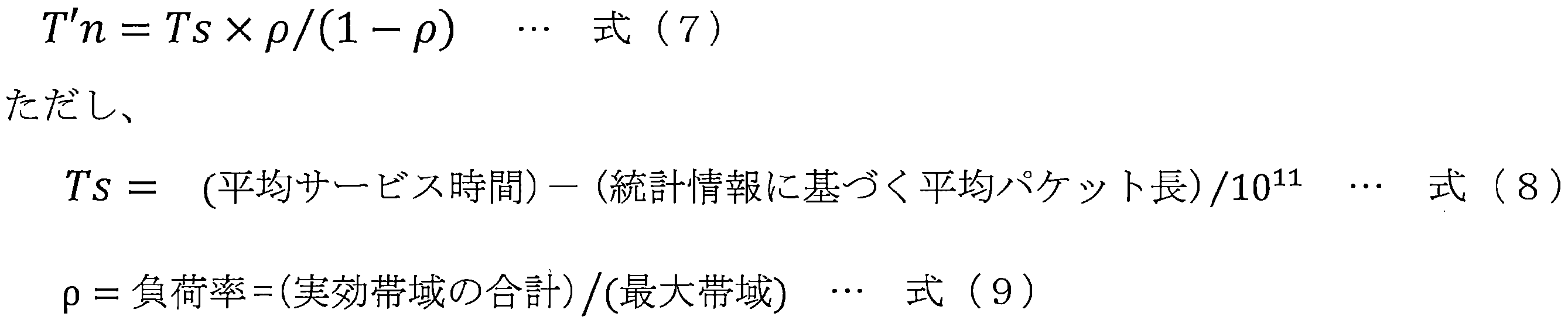
式(8)の右辺第1項の平均サービス時間とは、所定レートでパケットが転送されるとき、入力されたパケットが出力されるまでの時間を示す。例えば100Gbpsのレートでパケットが転送されるとき、1000byteのパケットが入力され、出力されるまでの平均サービス時間は、1000×8×10-11秒等となる。
式(8)の右辺第2項の分子である平均パケット長とは、合流ポイントのノード装置20から収集した実トラヒックの統計情報として収集されたパケット長に関して所定期間内の平均値を示す。式(8)の右辺第2項の分母である1011は1011[bps]を示す。また、式(9)の最右辺の分母である最大帯域とは、統計情報として収集した中での最大収容帯域を示す。なお、統計情報上の最大帯域の代わりに、設計上の最大帯域や統計情報上の平均帯域を用いても構わない。
式(9)の最右辺の分子である実効帯域の合計とは、合流ポイントで合流する各パスの実効帯域の和である。図7(c)の例では、合計とは4.4G+8G+30Gである。
前記式(7)のように平均サービス時間を導入することで、所定パスに対して合流する他のパスに、前記平均サービス時間の時間待ち合わせが発生し、揺らぎにつながることを反映することができる。また、平均サービス時間に対して負荷率を掛けることで、実際に衝突が起こり遅延の揺らぎが発生する実効的な値を見込むことができる。
式(8)の右辺第2項の分子である平均パケット長とは、合流ポイントのノード装置20から収集した実トラヒックの統計情報として収集されたパケット長に関して所定期間内の平均値を示す。式(8)の右辺第2項の分母である1011は1011[bps]を示す。また、式(9)の最右辺の分母である最大帯域とは、統計情報として収集した中での最大収容帯域を示す。なお、統計情報上の最大帯域の代わりに、設計上の最大帯域や統計情報上の平均帯域を用いても構わない。
式(9)の最右辺の分子である実効帯域の合計とは、合流ポイントで合流する各パスの実効帯域の和である。図7(c)の例では、合計とは4.4G+8G+30Gである。
前記式(7)のように平均サービス時間を導入することで、所定パスに対して合流する他のパスに、前記平均サービス時間の時間待ち合わせが発生し、揺らぎにつながることを反映することができる。また、平均サービス時間に対して負荷率を掛けることで、実際に衝突が起こり遅延の揺らぎが発生する実効的な値を見込むことができる。
また、前記式(7)等を用いる衝突発生確率を算出する方法において式(7)のT′nを合流ポイントで発生する遅延揺らぎとして用いたとき、パスnについてのパス全体での遅延揺らぎをTとすると、この遅延揺らぎTは下記の式(10)で示される。なお、式(10)において、衝突箇所についてのT′nの和は、別ラインカードから合流する背景トラヒックの入力の個数だけ積算することを意味する。

また、前記実施形態では、報知部16は、外部からパス情報として受け付けたパス条件では無瞬断パスとして設計できなかった旨(設定不可)をユーザに報知するものとしたが、それに加えて、他の情報を報知するオプション機能を備えることとしてもよい。
他の情報としては、例えば最大収容可能帯域を挙げることができる。これにより、ユーザは、無瞬断パスとして設計しようとしたパスが設定不可になった理由が、帯域不足によるものであることを認識することができる。
他の情報としては、例えば最大収容可能帯域を挙げることができる。これにより、ユーザは、無瞬断パスとして設計しようとしたパスが設定不可になった理由が、帯域不足によるものであることを認識することができる。
また、管理装置10は、ユーザが無瞬断パスとして設計しようとしたパスでは帯域不足となるような場合に、パス条件として入力されたパス経路とは異なる経路で帯域不足にならない経路を探索する機能をさらに備えるようにしてもよい。この場合には、報知部16は、オプション機能で報知する他の情報として、例えば、推奨される別経路の情報を挙げることができる。これにより、ユーザは、推奨される別経路が受け入れられる場合、無瞬断パスを設定することができる。
1 伝送システム
10 管理装置
11 新規パス情報入力部
12a 新規パス情報格納部
12b 既存パス情報格納部
13 統計情報収集部
14 無瞬断パス設計部
141 実効帯域算出部
142 遅延揺らぎ算出部
143 設定可否判定部
15 パス情報設定部
16 報知部
20(20a,20b,20c,20d) ノード装置
40 監視制御部
10 管理装置
11 新規パス情報入力部
12a 新規パス情報格納部
12b 既存パス情報格納部
13 統計情報収集部
14 無瞬断パス設計部
141 実効帯域算出部
142 遅延揺らぎ算出部
143 設定可否判定部
15 パス情報設定部
16 報知部
20(20a,20b,20c,20d) ノード装置
40 監視制御部
Claims (6)
- 送信ノードと受信ノードとの間に中継ノードからなる冗長経路を有する伝送システムの管理装置であって、
パス条件として少なくともパスの経路および収容帯域を含む新規パス情報を受け付けて新規パス情報格納部に格納する新規パス情報入力部と、
各ノードから少なくとも利用帯域およびパケット長を含む実トラヒックの統計情報を収集する統計情報収集部と、
前記新規パス情報を受け付けるたびに、前記収集された実トラヒックの統計情報に基づいて、パスの区間ごとの揺らぎに対しパス全体における遅延揺らぎを算出し、算出された遅延揺らぎが前記受信ノードにおけるバッファ量に応じた最大揺らぎ量よりも小さいパスを無瞬断パスとして設計する無瞬断パス設計部と、
前記無瞬断パスとして設計されたパスについて、当該パスの収容帯域を少なくとも含むパス情報を更新して既存パス情報格納部に格納すると共に、当該パスを構成するノードにおいて許容される帯域をパス情報として前記ノードに設定するパス情報設定部と、
前記無瞬断パスとして設計されなかったパスをユーザに報知する報知部と、
を備える伝送システムの管理装置。 - 前記無瞬断パス設計部は、
前記新規パス情報格納部に格納された収容帯域を更新する情報として、前記収集された実トラヒックの統計情報である利用帯域に基づいて実効帯域を算出する実効帯域算出部と、
前記ノードにおいて、異なるラインカードからの入力パケットが1つのラインカードから出力される際に合流ポイントで発生する遅延揺らぎを算出し、各合流ポイントで発生する遅延揺らぎを合計することで前記パス全体の遅延揺らぎを算出する遅延揺らぎ算出部と、
前記パス全体の遅延揺らぎを前記最大揺らぎ量より小さいか否かを判別し、前記パス全体の遅延揺らぎが前記最大揺らぎ量より小さい場合、設定可能と判定して前記無瞬断パスとして設計し、前記パス全体の遅延揺らぎが前記最大揺らぎ量以上である場合、設定不可と判定して前記報知部に通知する設定可否判定部と、
を備える請求項1に記載の伝送システムの管理装置。 - 前記遅延揺らぎ算出部は、前記合流ポイントにおいてパケット同士が最大パケット長で衝突する場合に発生する最大遅延揺らぎを算出することで、前記パス全体の遅延揺らぎを算出する請求項2に記載の伝送システムの管理装置。
- 前記遅延揺らぎ算出部は、前記収集された実トラヒックの統計情報である利用帯域および平均パケット長に基づく衝突発生確率を用いて前記合流ポイントで発生する遅延揺らぎを算出することで、前記パス全体の遅延揺らぎを算出する請求項2に記載の伝送システムの管理装置。
- 前記実効帯域算出部は、前記収集された実トラヒックの統計情報である利用帯域の所定期間における最大値に対して安全係数を掛けることで前記実効帯域を算出する請求項2から請求項4のいずれか一項に記載の伝送システムの管理装置。
- 送信ノードと受信ノードとの間に中継ノードからなる冗長経路を有する伝送システムの管理装置による伝送システムの設計方法であって、
前記管理装置が、
各ノードから少なくとも利用帯域およびパケット長を含む実トラヒックの統計情報を収集する工程と、
パス条件として少なくともパスの経路および収容帯域を含む新規パス情報を受け付けて新規パス情報格納部に格納する工程と、
前記新規パス情報を受け付けるたびに、前記収集された実トラヒックの統計情報に基づいて、パスの区間ごとの揺らぎに対しパス全体における遅延揺らぎを算出し、算出された遅延揺らぎが前記受信ノードにおけるバッファ量に応じた最大揺らぎ量よりも小さいパスを無瞬断パスとして設計する工程と、
前記無瞬断パスとして設計されたパスについて、当該パスの収容帯域を少なくとも含むパス情報を更新して既存パス情報格納部に格納すると共に、当該パスを構成するノードにおいて許容される帯域をパス情報として前記ノードに設定する工程と、
前記無瞬断パスとして設計されなかったパスをユーザに報知する工程と、
を含む伝送システムの設計方法。
Priority Applications (1)
| Application Number | Priority Date | Filing Date | Title |
|---|---|---|---|
| US17/255,131 US11411879B2 (en) | 2018-07-02 | 2019-06-27 | Transmission system management device and transmission system design method |
Applications Claiming Priority (2)
| Application Number | Priority Date | Filing Date | Title |
|---|---|---|---|
| JP2018-125786 | 2018-07-02 | ||
| JP2018125786A JP6950633B2 (ja) | 2018-07-02 | 2018-07-02 | 伝送システムの管理装置および伝送システムの設計方法 |
Publications (1)
| Publication Number | Publication Date |
|---|---|
| WO2020008989A1 true WO2020008989A1 (ja) | 2020-01-09 |
Family
ID=69060939
Family Applications (1)
| Application Number | Title | Priority Date | Filing Date |
|---|---|---|---|
| PCT/JP2019/025556 Ceased WO2020008989A1 (ja) | 2018-07-02 | 2019-06-27 | 伝送システムの管理装置および伝送システムの設計方法 |
Country Status (3)
| Country | Link |
|---|---|
| US (1) | US11411879B2 (ja) |
| JP (1) | JP6950633B2 (ja) |
| WO (1) | WO2020008989A1 (ja) |
Cited By (1)
| Publication number | Priority date | Publication date | Assignee | Title |
|---|---|---|---|---|
| WO2021181601A1 (ja) * | 2020-03-12 | 2021-09-16 | 三菱電機株式会社 | 光通信装置 |
Families Citing this family (2)
| Publication number | Priority date | Publication date | Assignee | Title |
|---|---|---|---|---|
| JP7247952B2 (ja) * | 2020-05-19 | 2023-03-29 | トヨタ自動車株式会社 | 設定装置、パラメータの設定方法及びプログラム |
| WO2026023025A1 (ja) * | 2024-07-25 | 2026-01-29 | Ntt株式会社 | 電子計算機 |
Citations (2)
| Publication number | Priority date | Publication date | Assignee | Title |
|---|---|---|---|---|
| JP2006074600A (ja) * | 2004-09-03 | 2006-03-16 | Fujitsu Ltd | 遅延保証パス設定システム |
| JP2012015668A (ja) * | 2010-06-30 | 2012-01-19 | Hitachi Ltd | 遅延を管理するトランスポート制御サーバ、ネットワークシステム及びトランスポート制御方法 |
Family Cites Families (7)
| Publication number | Priority date | Publication date | Assignee | Title |
|---|---|---|---|---|
| JP3986729B2 (ja) * | 2000-05-26 | 2007-10-03 | 富士通株式会社 | 遅延揺らぎ吸収制御方法およびその方法を利用する多重化装置 |
| EP1233573B1 (en) * | 2001-02-15 | 2008-03-26 | Oki Electric Industry Company, Limited | Network management system |
| JP2005503092A (ja) * | 2001-08-28 | 2005-01-27 | アイピーツーエイチ アーゲー | リレーシステムにおける通信パスを維持および/または質的に改良する方法 |
| JP5071165B2 (ja) * | 2007-03-19 | 2012-11-14 | 日本電気株式会社 | 経路多重化通信システム、通信ノード及び通信方法 |
| WO2013025146A2 (en) * | 2011-08-17 | 2013-02-21 | Telefonaktiebolaget L M Ericsson (Publ) | Method and controlling network node in a radio access network |
| JP6219233B2 (ja) | 2014-05-29 | 2017-10-25 | 日本電信電話株式会社 | 無瞬断切替装置および無瞬断切替方法 |
| JP6457340B2 (ja) * | 2015-06-05 | 2019-01-23 | 株式会社東芝 | 推定装置、システム、方法及びプログラム |
-
2018
- 2018-07-02 JP JP2018125786A patent/JP6950633B2/ja active Active
-
2019
- 2019-06-27 WO PCT/JP2019/025556 patent/WO2020008989A1/ja not_active Ceased
- 2019-06-27 US US17/255,131 patent/US11411879B2/en active Active
Patent Citations (2)
| Publication number | Priority date | Publication date | Assignee | Title |
|---|---|---|---|---|
| JP2006074600A (ja) * | 2004-09-03 | 2006-03-16 | Fujitsu Ltd | 遅延保証パス設定システム |
| JP2012015668A (ja) * | 2010-06-30 | 2012-01-19 | Hitachi Ltd | 遅延を管理するトランスポート制御サーバ、ネットワークシステム及びトランスポート制御方法 |
Cited By (3)
| Publication number | Priority date | Publication date | Assignee | Title |
|---|---|---|---|---|
| WO2021181601A1 (ja) * | 2020-03-12 | 2021-09-16 | 三菱電機株式会社 | 光通信装置 |
| JPWO2021181601A1 (ja) * | 2020-03-12 | 2021-09-16 | ||
| JP7258223B2 (ja) | 2020-03-12 | 2023-04-14 | 三菱電機株式会社 | 光通信装置 |
Also Published As
| Publication number | Publication date |
|---|---|
| US20210266266A1 (en) | 2021-08-26 |
| JP6950633B2 (ja) | 2021-10-13 |
| JP2020005221A (ja) | 2020-01-09 |
| US11411879B2 (en) | 2022-08-09 |
Similar Documents
| Publication | Publication Date | Title |
|---|---|---|
| US9397933B2 (en) | Method and system of providing micro-facilities for network recovery | |
| CN103081410B (zh) | 通信质量监视系统、通信质量监视方法 | |
| CN101656732A (zh) | 路径控制系统 | |
| KR101538244B1 (ko) | 서버 관리 장치, 서버 관리 방법, 및 프로그램 | |
| JP5784139B2 (ja) | 通信システム | |
| US20140093231A1 (en) | Procedure, apparatus, system, and computer program for network recovery | |
| Xie et al. | Designing a disaster-resilient network with software defined networking | |
| JP6950633B2 (ja) | 伝送システムの管理装置および伝送システムの設計方法 | |
| US12289196B2 (en) | Smart online link repair and job scheduling in machine learning supercomputers | |
| US9495256B2 (en) | Apparatus and method for switching a packet | |
| CN106533771B (zh) | 一种网络设备以及控制信息传输方法 | |
| US7426562B1 (en) | Method for network capacity planning with proper accounting of spare capacity | |
| EP2923464B1 (en) | Method and apparatus for allocating shared spare bandwidth for a flow on two disjoint routes between end nodes | |
| CN118802730A (zh) | 业务数据传输方法、装置、电子设备和存储介质 | |
| CN113347099A (zh) | 一种分布式网络流量转发方法、装置、设备及存储介质 | |
| Huang et al. | Resilient and Reliable Cloud Network Control for Mission-Critical Latency-Sensitive Applications | |
| JP2008283646A (ja) | ルータ装置 | |
| US20100260184A1 (en) | Control apparatus | |
| CN102769605B (zh) | 一种确定中继电路的方法及装置 | |
| JP3049301B2 (ja) | コネクション型通信網での障害回復方式および輻輳回復方式 | |
| CN119520233B (zh) | 网络设备失联后的自动恢复方法、系统、介质及电子设备 | |
| Samadi et al. | Reconfigurable optical dragonfly architecture for high performance computing | |
| EP4053694B1 (en) | Hardware-assisted fast data path switchover for a network device with redundant forwarding components | |
| Biswas et al. | A SDN-based on-demand path provisioning approach across multi-domain optical networks | |
| JP4900268B2 (ja) | アプリケーション通信制御装置及びプログラム |
Legal Events
| Date | Code | Title | Description |
|---|---|---|---|
| 121 | Ep: the epo has been informed by wipo that ep was designated in this application |
Ref document number: 19830205 Country of ref document: EP Kind code of ref document: A1 |
|
| NENP | Non-entry into the national phase |
Ref country code: DE |
|
| 122 | Ep: pct application non-entry in european phase |
Ref document number: 19830205 Country of ref document: EP Kind code of ref document: A1 |