WO2020008945A1 - 無線通信システム、制御方法、制御装置及び制御プログラム - Google Patents
無線通信システム、制御方法、制御装置及び制御プログラム Download PDFInfo
- Publication number
- WO2020008945A1 WO2020008945A1 PCT/JP2019/025097 JP2019025097W WO2020008945A1 WO 2020008945 A1 WO2020008945 A1 WO 2020008945A1 JP 2019025097 W JP2019025097 W JP 2019025097W WO 2020008945 A1 WO2020008945 A1 WO 2020008945A1
- Authority
- WO
- WIPO (PCT)
- Prior art keywords
- wireless
- wireless communication
- route
- value
- arrival
- Prior art date
- Legal status (The legal status is an assumption and is not a legal conclusion. Google has not performed a legal analysis and makes no representation as to the accuracy of the status listed.)
- Ceased
Links
Images




Classifications
-
- H—ELECTRICITY
- H04—ELECTRIC COMMUNICATION TECHNIQUE
- H04W—WIRELESS COMMUNICATION NETWORKS
- H04W40/00—Communication routing or communication path finding
- H04W40/02—Communication route or path selection, e.g. power-based or shortest path routing
- H04W40/12—Communication route or path selection, e.g. power-based or shortest path routing based on transmission quality or channel quality
- H04W40/14—Communication route or path selection, e.g. power-based or shortest path routing based on transmission quality or channel quality based on stability
-
- H—ELECTRICITY
- H04—ELECTRIC COMMUNICATION TECHNIQUE
- H04L—TRANSMISSION OF DIGITAL INFORMATION, e.g. TELEGRAPHIC COMMUNICATION
- H04L1/00—Arrangements for detecting or preventing errors in the information received
- H04L1/12—Arrangements for detecting or preventing errors in the information received by using return channel
- H04L1/16—Arrangements for detecting or preventing errors in the information received by using return channel in which the return channel carries supervisory signals, e.g. repetition request signals
- H04L1/18—Automatic repetition systems, e.g. Van Duuren systems
- H04L1/1867—Arrangements specially adapted for the transmitter end
- H04L1/1887—Scheduling and prioritising arrangements
-
- H—ELECTRICITY
- H04—ELECTRIC COMMUNICATION TECHNIQUE
- H04L—TRANSMISSION OF DIGITAL INFORMATION, e.g. TELEGRAPHIC COMMUNICATION
- H04L1/00—Arrangements for detecting or preventing errors in the information received
- H04L1/22—Arrangements for detecting or preventing errors in the information received using redundant apparatus to increase reliability
-
- H—ELECTRICITY
- H04—ELECTRIC COMMUNICATION TECHNIQUE
- H04W—WIRELESS COMMUNICATION NETWORKS
- H04W28/00—Network traffic management; Network resource management
- H04W28/02—Traffic management, e.g. flow control or congestion control
- H04W28/04—Error control
-
- H—ELECTRICITY
- H04—ELECTRIC COMMUNICATION TECHNIQUE
- H04W—WIRELESS COMMUNICATION NETWORKS
- H04W40/00—Communication routing or communication path finding
- H04W40/02—Communication route or path selection, e.g. power-based or shortest path routing
-
- H—ELECTRICITY
- H04—ELECTRIC COMMUNICATION TECHNIQUE
- H04W—WIRELESS COMMUNICATION NETWORKS
- H04W84/00—Network topologies
- H04W84/18—Self-organising networks, e.g. ad-hoc networks or sensor networks
Definitions
- the present invention relates to a wireless communication system, a control method, a control device, and a control program.
- a wireless communication system a transmitter that performs redundant communication for transmitting the duplicated packet by using wireless frames in a plurality of frequency bands, and a receiver that acquires the earliest normally received wireless frame as a packet. May be provided.
- Such a wireless communication system can realize high reliability with respect to a packet arrival probability (a wireless frame arrival probability) within a required delay time even in an environment where a wireless frame loss probability is high. Reference 1).
- Each wireless communication system shown in FIGS. 11 to 13 includes three wireless communication devices. Between each wireless communication device, there is a wireless section constituting a wireless multi-hop route. The wireless communication devices communicate with each other via a wireless section of the selected route. A plurality of wireless links may exist in one wireless section. The wireless communication device can execute redundant communication using a plurality of wireless links.
- FIG. 11 is a diagram illustrating a first example of selection of a wireless multi-hop route.
- the wireless communication system selects the first wireless section as the shortest path so that the number of hops (the number of wireless sections of the path) is reduced.
- frame loss rate the loss rate of a wireless frame
- redundant communication using a plurality of wireless links is required.
- the resource consumption of the shortest path (first wireless section) may be greater than the resource consumption of the non-shortest path (second wireless section and third wireless section).
- FIG. 12 is a diagram illustrating a second example of selection of a wireless multi-hop route.
- the wireless communication system determines whether or not the requested packet arrival probability is satisfied, that is, whether or not the requested reliability (hereinafter, referred to as “required reliability”) is satisfied for each wireless section. judge. However, even if the route satisfies the required reliability in each wireless section, the route may not satisfy the required reliability from the start point to the end point (the wireless communication device A and the wireless communication device Z) of the route. .
- the required reliability is, for example, the reliability that the ratio of packets (wireless frames) arriving within seven times of transmission is 99.99% or more.
- the frame loss rate in the first wireless section is, for example, 10%.
- the frame loss rate in the second wireless section is, for example, 20%.
- the required reliability is satisfied in the first wireless section (the ratio of packets arriving within seven transmissions is 99.999999%).
- the required reliability is satisfied (the ratio of packets arriving within 7 transmissions is 99.99872%).
- the required reliability is not satisfied between the wireless communication device A and the wireless communication device Z (the ratio of packets arriving within seven times is 99.98856%).
- the control device of the wireless communication system may select a route that does not satisfy the required reliability in this way.
- FIG. 13 is a diagram illustrating a third example of selection of a wireless multi-hop route.
- the control device of the wireless communication system divides a required delay (hereinafter, referred to as a “request delay”) according to the number of hops of a path from a start point to an end point.
- the control device of the wireless communication system determines the required reliability for each wireless section based on the division result.
- the required delay is expressed by using the upper limit of the number of transmissions of the radio frame.
- the required reliability is a reliability that, for example, the ratio of packets arriving at a transmission count of eight or less in the path from the wireless communication device A to the wireless communication device Z is 99.99% or more.
- the required reliability of each wireless section requires that the ratio of packets arriving within four times of transmission be 99.99% or more.
- the upper limit of the number of transmissions, which is the required delay, of eight times is divided by the number of hops “2”, so that the upper limit of the number of transmissions of each wireless section is set to four or less.
- the frame loss rate in the first wireless section is, for example, 15%.
- the frame loss rate in the second wireless section is, for example, 20%.
- the ratio of packets arriving with the number of transmissions of four or less is 99.949375% in the first wireless section and 99.84% in the second wireless section. Therefore, it is determined that neither the first wireless section nor the second wireless section satisfies the required reliability.
- the ratio of packets arriving within eight transmissions between the wireless communication device A and the wireless communication device Z is 99.9960581%, which satisfies the required reliability.
- the wireless communication system erroneously determines that the first wireless section and the second wireless section satisfying the required reliability are wireless sections that do not satisfy the required reliability. Based on this erroneous determination, the wireless communication system may perform unnecessary redundant communication.
- a wireless frame passes through a plurality of wireless sections as in a wireless multi-hop in a wireless access network (wireless backhaul), even if one wireless section satisfies the required reliability, a route including a plurality of wireless sections is required. Between endpoints, the path may not meet the required reliability.
- the conventional control device may not be able to select a path that satisfies the required reliability and required delay for wireless multi-hop.
- an object of the present invention is to provide a wireless communication system, a control method, a control device, and a control program capable of selecting a path that satisfies required reliability and required delay for wireless multi-hop. .
- One embodiment of the present invention is a wireless communication system including three or more wireless communication devices and a control device, wherein the control device includes a plurality of wireless communication devices from a first wireless communication device to a second wireless communication device.
- the control device includes a plurality of wireless communication devices from a first wireless communication device to a second wireless communication device.
- a setting unit that determines, for each of the routes, a total power value that is a result of the sum of the arrival probabilities of the wireless frames for each of the wireless sections configuring the route, and the number of transmissions of the wireless frame for each of the routes is
- a search unit that selects the path whose number is equal to or less than a predetermined number and whose total power value is equal to or more than a predetermined threshold.
- One aspect of the present invention is the wireless communication system described above, wherein the setting unit calculates a logarithmic value of a surplus event of a predetermined arrival probability, and calculates a total arrival probability of the radio frame for each of the plurality of routes in the wireless section.
- the number of transmissions of the radio frame is determined based on a result obtained by dividing the result of the multiplication by the logarithmic value of the surplus event.
- One aspect of the present invention is the wireless communication system described above, wherein the setting unit is configured such that, when the number of transmissions of the radio frame for each path exceeds the predetermined number, the total power is the largest.
- the wireless section in which the arrival probability of the wireless frame is less than a predetermined probability in the path is detected, and the redundancy of communication in the detected wireless section is increased.
- One embodiment of the present invention is a control method executed by a wireless communication system including three or more wireless communication devices and a control device, wherein the control device is configured to perform a second wireless communication from a first wireless communication device.
- a total power value which is a result of summing the arrival probabilities of wireless frames for each wireless section constituting the route, is determined for each of the routes, and the number of transmissions of the wireless frame for each route Is less than or equal to a predetermined number of times and the total power value is greater than or equal to a predetermined threshold.
- One aspect of the present invention is the above wireless communication method, wherein the control device calculates a logarithmic value of a surplus event of a predetermined arrival probability, and calculates a total of the arrival probabilities of the wireless frames for the plurality of routes in the wireless section.
- the number of transmissions of the radio frame is determined based on a result obtained by dividing the result of the multiplication by the logarithmic value of the surplus event.
- One aspect of the present invention is a wireless communication apparatus, comprising: a plurality of routes from a first wireless communication device to a second wireless communication device among three or more wireless communication devices; A setting unit that determines, for each of the routes, a total power value that is a result of the sum of the arrival probabilities, the number of transmissions of the radio frame for each of the routes is equal to or less than a predetermined number, and the total power value is equal to or greater than a predetermined threshold value And a search unit for selecting the route.
- One aspect of the present invention is the wireless communication apparatus described above, wherein the setting unit calculates a logarithmic value of a surplus event of the predetermined arrival probability, and calculates a total of the arrival probabilities of the radio frames for the plurality of routes in the radio section.
- the number of transmissions of the radio frame is determined based on a result obtained by dividing the result of the multiplication by the logarithmic value of the surplus event.
- One embodiment of the present invention is a control program for causing a computer to function as the control device.
- FIG. 1 is a diagram illustrating a configuration example of a wireless communication system in an embodiment. It is a figure in an embodiment which shows the example of an arrival probability total square path
- FIG. 3 is a diagram illustrating a configuration example of a control device in the embodiment.
- FIG. 3 is a diagram illustrating an example of topology data in the embodiment.
- FIG. 4 is a diagram illustrating an example of a path tree data table in the embodiment.
- 9 is a flowchart illustrating an example of a procedure for setting a route tree data table with priority given to the arrival probability over the number of hops in the embodiment.
- 9 is a flowchart illustrating an example of a procedure for setting a path tree data table by giving priority to the number of hops over the arrival probability in the embodiment.
- FIG. 6 is a flowchart illustrating an example of a procedure for setting a redundancy satisfying required reliability in the embodiment.
- FIG. 8 is a diagram illustrating an example of the number of transmissions that satisfies the required reliability according to the arrival probability total value in the embodiment.
- 9 is a flowchart illustrating an example of details of a delay calculation process according to the embodiment.
- FIG. 9 is a diagram illustrating a first example of conventional wireless multi-hop route selection.
- FIG. 13 is a diagram illustrating a second example of conventional wireless multi-hop route selection.
- FIG. 11 is a diagram illustrating a third example of conventional wireless multi-hop route selection.
- FIG. 1 is a diagram illustrating a configuration example of the wireless communication system 1.
- the wireless communication system 1 is a system that executes wireless multi-hop communication in a wireless access network (wireless backhaul).
- the wireless communication system 1 includes a plurality of wireless communication devices 2 and a control device 3.
- the wireless communication device 2 executes wireless multi-hop communication using a wireless frame (packet) transmitted on a route determined by one or more wireless sections selected by the control device 3.
- the wireless communication device 2 on the transmission side executes redundant communication for transmitting the copied packet using wireless frames in a plurality of frequency bands.
- the wireless communication device 2 on the receiving side obtains, as a packet, the wireless frame normally received first.
- the control device 3 selects a path that satisfies the required reliability and the required delay for the wireless multi-hop from the arrival probability total squared path tree.
- the total arrival probability path tree is a path tree having each wireless communication device 2 as a node, and is a path tree representing a total arrival probability value.
- the arrival probability sum value is a value obtained by summing the arrival probability of a packet along the route.
- FIG. 2 is a diagram showing an example of the arrival probability total power path tree.
- each symbol from “A” to “F” represents each wireless communication device 2.
- the wireless communication device 2 is a node (point), and the wireless section is a link.
- the starting point of the arrival probability total power path tree is the wireless communication device to which the code A is assigned.
- the arrival probability of a packet between the wireless communication device (start point) to which the code A is assigned and the wireless communication device (end point) to which the code B is assigned is 0.8.
- FIG. 3 is a diagram illustrating a configuration example of the control device 3.
- the control device 3 includes a storage unit 30 and a route search unit 31.
- the storage unit 30 is a non-volatile recording medium (non-temporary recording medium) such as a flash memory and a hard disk drive (HDD).
- the storage unit 30 may include, for example, a volatile recording medium such as a RAM (Random Access Memory) or a register.
- the storage unit 30 stores the topology data 300 as a topology data storage unit.
- the storage unit 30 stores a path tree data table 301 as a data table storage unit.
- the storage unit 30 may store a program executed by the route search unit 31.
- the path search unit 31 is realized by a processor such as a CPU (Central Processing Unit) executing a program stored in the storage unit.
- the route search unit 31 may be realized using hardware such as an LSI (Large Scale Integration) or an ASIC (Application Specific Integrated Circuit).
- the route search unit 31 includes a setting unit 310 and a search unit 311.
- the setting unit 310 sets a data table (hereinafter, referred to as a “path tree data table”) of the arrival probability total power path tree.
- the setting unit 310 is a result of summing the arrival probabilities of the wireless frames for each of the wireless sections constituting the route for a plurality of routes from the first wireless communication device 2 to the second wireless communication device 2.
- the total power is determined for each route as the arrival probability total power.
- the search unit 311 selects a path that satisfies the required reliability and required delay for wireless multi-hop from the arrival probability total squared path tree. That is, the search unit 311 selects the route having the highest total arrival probability total value from the total arrival probability total path tree.
- FIG. 4 is a diagram illustrating an example of the topology data 300.
- the topology data 300 is topology data of a total probability path tree of arrival probability.
- the wireless section the number of available wireless links, the available channels, and the arrival probability (not including retransmission) of wireless frames are associated with each other.
- the wireless section “AB” the number of available wireless links is, for example, “2”
- the available channels are, for example, “ch40”
- the likelihood of the wireless frame of “ch40” (not including retransmission). ) Is, for example, 0.8.
- FIG. 5 is a diagram showing an example of a path tree data table.
- a route that prioritizes the arrival probability when the wireless communication device to which code B is assigned is the starting point and the wireless communication device to which code A is assigned is the final fixed point
- a path tree data table showing a state in the middle of the search is shown as an example.
- FIG. 6 is a flowchart illustrating an example of a procedure for setting a path tree data table with priority given to the arrival probability over the number of hops.
- the wireless communication system 1 executes the operation procedure shown in FIG. 6 when the network of the wireless communication device 2 is established.
- the setting unit 310 determines whether or not there is a wireless communication device 2 whose starting point has not been calculated in the path tree data table (the progress of the search process) (step S101). If there is no wireless communication device at the starting point whose calculation status has not been set in the path tree data table (step S101: NO), the setting unit 310 ends the processing of setting the path tree data table.
- step S101 When there is a wireless communication device whose calculation status is not yet available in the path tree data table (step S101: YES), the setting unit 310 determines one of the wireless communication devices whose calculation status is not available. It is selected as the starting point of the search processing (step S102).
- the setting unit 310 For a cell having the same start point and end point in the path tree data table, the setting unit 310 sets the arrival probability total value (initial cost) to 1, the number of hops to 0, the upstream flag to zero, and sets the decision flag. Set to confirm. The setting unit 310 selects the starting point as the final fixed point (Step S103).
- the setting unit 310 passes a point adjacent to the final determined point (hereinafter, referred to as an “adjacent point”), that is, one wireless section in the arrival probability total path tree having the wireless communication device 2 as a node (point). Then, among the points connected to the final fixed point, all the points whose fixed flag is “not yet recorded” are recorded in the list (step S104).
- the setting unit 310 determines whether the list is an empty set (step S105). If the list is an empty set (step S105: YES), the setting unit 310 proceeds to step S111. If the list is not an empty set (one or more points whose fixed flag is “not yet” are recorded in the list) (step S105: NO), the setting unit 310 selects one adjacent point from the list (step S105). Step S106).
- the setting unit 310 calculates the sum of the powers of the “final arrival total power value” of the final fixed point and the arrival probability (not including retransmission) of the frame in the wireless section between the selected final fixed point and the adjacent point.
- the value is calculated as the total sum of the arrival probabilities of the selected adjacent points (step S107).
- the setting unit 310 calculates a total arrival probability value instead of calculating an added value of communication costs.
- the setting unit 310 sets the case where the “total arrival probability total value” of the adjacent point in the path tree data table is “not yet”, and the “total arrival probability total value of the adjacent point in the path tree data table” than the calculated total value. It is determined whether the “value” is larger than one of the cases (step S108).
- step S108 YES
- step S110 the setting unit 310 determines that the “total probability value of arrival probability” of the adjacent point is equal to the calculated total value and the “hop number” of the adjacent point. Is larger than the “hop number” of the final fixed point by 2 or more (step S109).
- step S109 NO
- the setting unit 310 returns the process to step S105.
- the setting unit 310 sets the calculated total power value to the “arrival probability total power value” of the selected adjacent point.
- the setting unit 310 sets a final fixed point with respect to “upstream” of the selected adjacent point.
- the setting unit 310 sets a value obtained by adding 1 to the “hop number” of the final fixed point for the “hop number” of the selected adjacent point (step S110).
- the setting unit 310 returns the process to step S105.
- the setting unit 310 selects, as a final confirmed point, a point having the largest total arrival probability value from among the points for which the finalization flag is “not yet” and the total arrival probability value is set.
- the setting unit 310 sets the confirmation flag to “confirmed” for the selected final confirmation point (step S111).
- the setting unit 310 determines whether or not the finalization flag is “determined” at all end points with respect to the start point selected in step S102 (the selected start point) (step S112). If the finalization flag is “not yet” at any end point with respect to the starting point selected in step S102 (step S112: NO), the setting unit 310 returns the process to step S104. When the finalization flag is “confirmed” at all the end points for the starting point selected in step S102 (step S112: YES), the setting unit 310 sets the calculation status of the starting point selected in step S102 to “done”. (Step S113).
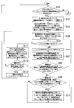
- FIG. 7 is a flowchart showing an example of a procedure for setting a path tree data table by giving priority to the number of hops over the arrival probability.
- the wireless communication system 1 executes the operation procedure shown in FIG. 7 when the network of the wireless communication device 2 is established. Steps S201 to S207 are the same as steps S101 to S107 shown in FIG.
- the setting unit 310 determines that the “hop number” of the adjacent point in the path tree data table is “not yet” and that the “hop number” of the selected adjacent point is two or more larger than the “hop number” of the final fixed point. It is determined whether any of the above cases is satisfied (step S208).
- step S208: YES If any of those cases (step S208: YES), the setting unit 310 advances the process to step S210. If neither of these cases is true (step S208: NO), the setting unit 310 determines that the “hop number” of the adjacent point and the “hop number” of the final fixed point are equal and smaller than the calculated total power value. It is determined whether the “total power of arrival probability” of the adjacent point is large (step S209).
- step S109 NO.
- the setting unit 310 returns the process to step S205.
- Step S210 If the “hop number” of the adjacent point is equal to the “hop number” of the final fixed point, and the “arrival probability total square value” of the adjacent point is larger than the calculated total square value (step S209: YES), The setting unit 310 proceeds with the process to step S210. Steps S210 to S213 are the same as steps S110 to S113 shown in FIG.
- the redundancy is the number of wireless links used for communication in the same wireless section at the same time.
- the redundancy is set for each wireless section.
- the number of wireless links available in the wireless section “AB” is two.
- the setting unit 310 can set the redundancy up to “2”.
- the setting unit 310 sets a value equal to or smaller than the smaller number among the numbers of wireless units (antennas) of the two wireless communication devices constituting both ends of the wireless section in the “available wireless” in the topology data 300. Set to "Number of links".
- the wireless communication device executes redundant communication using two wireless links simultaneously.
- the wireless communication device on the transmitting side copies one packet transmitted in the same wireless section to both of two wireless links used simultaneously in the wireless section.
- the transmitting-side wireless communication device transmits the duplicated packet to the receiving-side wireless communication device using two wireless links.
- the wireless communication device on the receiving side acquires the packet that has arrived first among the two copied packets.
- the wireless communication device on the receiving side discards packets other than the packet that has arrived first.
- the arrival probability (not including retransmission) of the packet of the first radio link is 0.80 (80%)
- the probability that one of the wireless frames copied in one redundant communication will arrive is 0.95 (95%).
- the wireless communication device can increase the reliability of the wireless section by the redundant communication.
- the wireless communication device allocates a different channel to each wireless link used for redundant communication.
- Each wireless communication device includes a sufficient number of wireless units (antennas) that can assign different channels to each wireless link.
- the setting unit 310 detects a radio section in which the arrival probability of the radio frame is less than the predetermined probability on the path having the maximum total power.
- the setting unit 310 may increase the redundancy of communication in the detected wireless section.
- FIG. 8 is a flowchart illustrating an example of a procedure for setting the redundancy that satisfies the required reliability.
- the setting unit 310 executes the operation procedure shown in FIG. 8 after executing the operation procedure shown in FIG. 6 or FIG.
- the setting unit 310 uses the information indicating the required delay, the information indicating the required arrival probability, and the information indicating the two wireless communication devices that execute the wireless communication as a wireless communication start request that satisfies the required reliability. Obtain (step S301). The setting unit 310 selects a route between two points to execute wireless communication in the total arrival probability tree (step S302). The setting unit 310 executes a delay calculation process for calculating the worst delay value of the frame (step S303).
- the setting unit 310 determines whether the calculated delay value is equal to or less than the required delay (step S304). When the calculated delay value is equal to or less than the required delay (step S304: YES), the setting unit 310 proceeds with the process to step S308.
- the setting unit 310 determines, from among one or more wireless sections in which the redundancy can be increased, the wireless frame having the lowest arrival probability of the wireless frame. It is determined whether or not a section exists. If there is a wireless section with the lowest radio frame arrival probability, the radio section with the lowest radio frame arrival probability is selected (step S305).
- step S305 If there is no wireless section with the lowest wireless frame arrival probability (step S305: no wireless section capable of increasing the redundancy), the setting unit 310 proceeds to step S307. If there is a wireless section with the lowest radio frame arrival probability (step S305: there is a wireless section in which redundancy can be increased), the setting unit 310 determines the number of transmissions that satisfy the required reliability in the selected wireless section. Is calculated (step S306). The setting unit 310 returns the process to step S303.
- the setting unit 310 outputs information indicating that a route satisfying the required reliability has not been detected, and ends the process of setting the redundancy (step S307).
- the setting unit 310 sets the redundancy in the communication function unit of the wireless communication device 2 (step S308).
- the setting unit 310 outputs information indicating that there is a path satisfying the required reliability, and ends the process of setting the redundancy (step S309).
- FIG. 9 is a diagram illustrating an example of the number of transmissions that satisfies the required reliability according to the total value of the arrival probabilities.
- the wireless communication device to which the code A is assigned is the starting point, and the wireless communication device to which the code Z is assigned is the end point.
- the total arrival probability value is equal to the frame arrival probability from the start point to the end point, and is 0.72.
- the wireless communication device to which the code A is assigned is a starting point
- the wireless communication device to which the code M is assigned is a relay point
- the wireless communication device to which the code Z is assigned is an end point.
- the total sum of the arrival probabilities is the total sum “0.72” of the frame arrival probability 0.9 from the start point to the relay point and the frame arrival probability 0.8 from the relay point to the end point.
- the total arrival probability power value is a total power value “0.81” of the frame arrival probability 0.9 from the start point to the relay point and the frame arrival probability 0.9 from the relay point to the end point.
- FIG. 10 is a flowchart showing an example of the details of the delay calculation process (step S303 shown in FIG. 8).
- the setting unit 310 calculates the minimum value of the number of times of transmission of the frame.
- Setting section 310 calculates the worst delay value based on the calculated minimum value of the number of transmissions.
- the setting unit 310 can accurately calculate the worst delay value based on the minimum value S of the number of times of transmission of a frame satisfying the required reliability.
- the minimum value S of the number of times of transmission of a frame that satisfies the required reliability is represented by Expression (1).
- R represents a probability (99.99% or the like) serving as a reference for required reliability.
- s represents the number of transmissions of a frame in which the packet arrives between the end points of the route with the packet arrival probability R or more.
- S represents the minimum value of the number of transmissions s of the frame.
- k represents the number of hops between the end points of the route.
- ij represents the number of transmissions of the frame on the radio link with the hop index j.
- r j represents the arrival probability of the frame on the radio link with the hop index j.
- the setting unit 310 can calculate the approximate value of the worst delay value with a small amount of calculation based on the approximate value of the minimum value S of the number of times of transmission of the frame satisfying the required reliability.
- the approximate value of the minimum value S of the number of times of transmission of the frame satisfying the required reliability is represented by Expression (2).
- R represents a probability (99.99% or the like) serving as a reference for required reliability.
- s represents the number of transmissions of a frame in which the packet arrives between the end points of the route with the packet arrival probability R or more.
- S represents an approximate value of the minimum value of the number of transmissions s of the frame.
- F represents a residual event (1-R).
- ln represents a natural logarithm.
- k represents the number of hops between the end points of the route.
- r j represents a frame arrival probability on the radio link with the index j of the hop. 1 1 ⁇ j ⁇ kr j represents the frame arrival probability summed up over the entire path.
- f represents a residual event (1 ⁇ 1 ⁇ j ⁇ k r j ).
- the setting unit 310 can calculate the approximate value of the worst delay value based on the approximate value S of the minimum value of the number of times of transmission of the frame satisfying the required reliability.
- the calculation amount of Expression (2) is O (1).
- the setting unit 310 determines a smaller value based on a better approximation of the minimum value S of the number of transmissions of the frame satisfying the required reliability.
- a better approximation of the worst delay value can be calculated with a calculation amount.
- a better approximation S ′ of the minimum value of the number of times of transmission of the frame satisfying the required reliability is expressed by Expression (3).
- the wireless communication system 1 includes three or more wireless communication devices 2 and the control device 3.
- the control device 3 includes a setting unit 310 and a search unit 311.
- the setting unit 310 calculates, for a plurality of routes from the first wireless communication device 2 to the second wireless communication device 2, the arrival probabilities of wireless frames (packets) for each wireless section constituting the route, which are summed up. A certain arrival probability total value is determined for each route.
- the search unit 311 selects a route in which the number of times of transmission of the radio frame for each route is equal to or less than a predetermined number (the number of times satisfying the required delay) and the total probability of arrival is equal to or greater than a predetermined threshold (a value satisfying the required reliability). .
- the search unit 311 may select the route having the highest total arrival probability value.
- the wireless communication system 1 can select a path that satisfies the required reliability and required delay for wireless multi-hop.
- the control device 3 can construct a route such as a wireless backhaul that satisfies the required reliability between end points of a route passing through a plurality of wireless sections.
- the control device 3 can improve the accuracy of determining whether or not the required reliability is satisfied in wireless multi-hop.
- the control device 3 determines not the path with the simplest number of hops (the path with the minimum average delay) but the path that easily satisfies the required reliability (the worst delay value is the minimum). ) Can be selected.
- the control device 3 can construct a route that satisfies the required reliability between endpoints of a route that passes through a plurality of wireless sections, such as a wireless backhaul. Therefore, the control device 3 can extend the connection distance of the highly reliable wireless communication.
- the setting unit 310 uses the arrival probability (not including retransmission) of the wireless frame in each wireless section instead of using the cost in the algorithm for calculating the shortest path tree.
- the setting unit 310 executes the sum of the arrival probabilities instead of adding the cost.
- the setting unit 310 selects the maximum arrival probability in the arrival probability comparison instead of selecting the minimum cost in the cost comparison.
- the setting unit 310 calculates the arrival probability total squared path tree table by setting the initial cost at the starting point of the path to 1.
- the search unit 311 determines the route having the smallest number of hops. May be selected.
- the setting unit 310 uses an algorithm for calculating the shortest path tree to compare the routes having the same number of hops and to determine the arrival probability (retransmission rate) of a wireless frame in each wireless section on the route. (Excluding) is selected.
- the setting unit 310 calculates the arrival probability (which may include retransmission) of the wireless frame in each wireless section based on the required reliability indicating the packet arrival probability within the required time, as in Expression (1).
- the setting unit 310 calculates the number of transmissions of a radio frame in which the same radio frame can be transmitted with a predetermined arrival probability or higher (including retransmission) in each radio section.
- the setting unit 310 is required for a route between two points in the route tree based on the result of adding all the values of the number of transmissions calculated for each wireless section for the entire wireless section of the route with the highest arrival probability.
- the number of times of transmission of a radio frame that can transmit the radio frame while satisfying the arrival probability (requested reliability) is calculated.
- the setting unit 310 calculates the logarithmic value of the surplus event of the predetermined arrival probability as the expression (2) or the expression (3), and calculates the remainder of the sum of the arrival probabilities of the radio frames for the radio sections for a plurality of routes.
- the number of transmissions of the radio frame may be determined based on the result obtained by dividing the logarithm of the event.
- the control device 3 calculates a route that passes through a plurality of wireless sections such as a wireless backhaul, and uses a probability R that is a reference of required reliability between the two wireless communication devices on the calculated route,
- the worst delay value of the route can be calculated based on the formula (1), the formula (2) or the formula (3).
- the control device 3 can set the redundancy of each wireless section so that the worst delay value is equal to or less than the required delay.
- the control device and the wireless communication device in the above-described embodiment may be realized by a computer.
- a program for realizing this function may be recorded on a computer-readable recording medium, and the program recorded on this recording medium may be read and executed by a computer system.
- the “computer system” includes an OS and hardware such as peripheral devices.
- the “computer-readable recording medium” refers to a portable medium such as a flexible disk, a magneto-optical disk, a ROM, and a CD-ROM, and a storage device such as a hard disk built in a computer system.
- a “computer-readable recording medium” refers to a communication line for transmitting a program via a network such as the Internet or a communication line such as a telephone line, which dynamically holds the program for a short time.
- a program may include a program that holds a program for a certain period of time, such as a volatile memory in a computer system serving as a server or a client in that case.
- the program may be for realizing a part of the functions described above, or may be a program that can realize the functions described above in combination with a program already recorded in a computer system, It may be realized using a programmable logic device such as an FPGA (Field Programmable ⁇ Gate ⁇ Array).
- FPGA Field Programmable ⁇ Gate ⁇ Array
- the present invention is applicable to a wireless communication system.
Landscapes
- Engineering & Computer Science (AREA)
- Computer Networks & Wireless Communication (AREA)
- Signal Processing (AREA)
- Mobile Radio Communication Systems (AREA)
Abstract
無線通信システムは、3以上の無線通信装置と、制御装置とを備える無線通信システムであって、制御装置は、第1の無線通信装置から第2の無線通信装置までの複数の経路について、経路を構成する無線区間ごとの無線フレームの到達確率が総乗された結果である総乗値を経路ごとに定める設定部と、経路ごとの無線フレームの送信回数が所定回数以下であり、総乗値が所定閾値以上である経路を選択する探索部とを備える。
Description
本発明は、無線通信システム、制御方法、制御装置及び制御プログラムに関する。
無線通信システムが、複製されたパケットを複数の周波数帯の無線フレームを利用して送信する冗長通信を実行する送信機と、最先で正常に受信された無線フレームをパケットとして取得する受信機とを備える場合がある。このような無線通信システムは、無線フレームの損失確率が高い環境であっても、要求される遅延時間内のパケット到達確率(無線フレーム到達確率)に関して高い信頼性を実現することができる(非特許文献1参照)。
図11から図13までに示された各無線通信システムは、3台の無線通信装置を備える。各無線通信装置の間には、無線マルチホップ経路を構成する無線区間が存在する。無線通信装置は、選択された経路の無線区間を介して、互いに通信する。一つの無線区間には、複数の無線リンクが存在してもよい。無線通信装置は、複数の無線リンクを利用して冗長通信を実行することができる。
図11は、無線マルチホップ経路の選択の第1例を示す図である。図11では、無線通信システムは、ホップ数(経路の無線区間の数)が少なくなるように、第1無線区間を最短経路として選択する。しかしながら、最短経路の第1無線区間(無線リンク)において無線フレームの損失率(以下「フレーム損失率」という。)が高い場合には、複数の無線リンクを利用した冗長通信が必要となる。このため、最短経路(第1無線区間)のリソース消費は、最短でない経路(第2無線区間及び第3無線区間)のリソース消費よりも多くなることがある。
図12は、無線マルチホップ経路の選択の第2例を示す図である。図12では、無線通信システムは、要求されたパケット到達確率を満たすか否かを、すなわち、要求された信頼性(以下「要求信頼性」という。)を満たすか否かを、無線区間ごとに判定する。しかしながら、各無線区間では経路が要求信頼性を満たしている場合でも、経路の起点から終点まで(無線通信装置A及び無線通信装置Z)の間では、経路が要求信頼性を満たさない場合がある。
図12では、要求信頼性は、例えば7回以内の送信回数で到達するパケット(無線フレーム)の割合が99.99%以上であるという信頼性である。第1無線区間のフレーム損失率は、例えば10%である。第2無線区間のフレーム損失率は、例えば20%である。
この場合、第1無線区間では要求信頼性が満たされている(7回以内の送信回数で到達するパケットの割合は、99.99999%である)。第2無線区間では要求信頼性が満たされている(7回以内の送信回数で到達するパケットの割合は、99.99872%である)。しかしながら、無線通信装置A及び無線通信装置Zの間では、要求信頼性が満たされていない(7回以内に到達するパケットの割合は、99.98856%である)。無線通信システムの制御装置は、このように要求信頼性を満たさない経路を選択してしまう場合がある。
この場合、第1無線区間では要求信頼性が満たされている(7回以内の送信回数で到達するパケットの割合は、99.99999%である)。第2無線区間では要求信頼性が満たされている(7回以内の送信回数で到達するパケットの割合は、99.99872%である)。しかしながら、無線通信装置A及び無線通信装置Zの間では、要求信頼性が満たされていない(7回以内に到達するパケットの割合は、99.98856%である)。無線通信システムの制御装置は、このように要求信頼性を満たさない経路を選択してしまう場合がある。
図13は、無線マルチホップ経路の選択の第3例を示す図である。図13では、無線通信システムの制御装置は、要求される遅延(以下「要求遅延」という。)を、起点から終点までの経路のホップ数に応じて分割する。無線通信システムの制御装置は、分割結果に基づいて、無線区間ごとに要求信頼性を判定する。要求遅延は、無線フレームの送信回数の上限を用いて表現される。
図13では、要求信頼性は、無線通信装置Aから無線通信装置Zまでの経路において、例えば8回以内の送信回数で到達するパケットの割合が99.99%以上であるという信頼性である。この要求信頼性を満たすためには、無線区間ごとの要求信頼性は、4回以内の送信回数で到達するパケットの割合が99.99%以上である必要がある。ここで、要求遅延である送信回数の上限8回をホップ数「2」で分割することによって、各無線区間の送信回数の上限は4回以内とされた。
第1無線区間のフレーム損失率は、例えば15%である。第2無線区間のフレーム損失率は、例えば20%である。この場合、4回以内の送信回数で到達するパケットの割合は、第1無線区間では99.949375%であり、第2無線区間では99.84%である。したがって、第1無線区間と第2無線区間とはいずれも要求信頼性を満たさないと判定される。しかしながら、無線通信装置Aと無線通信装置Zの間では、8回以内の送信回数で到達するパケットの割合が99.9960581%であり、要求信頼性は満たされている。このように、無線通信システムは、要求信頼性を満たしている第1無線区間と第2無線区間とを、要求信頼性を満たさない無線区間であると誤判定する。この誤判定に基づいて、無線通信システムは、不必要な冗長通信を実行してしまう場合がある。
宗、納谷、藤田、吉澤、清水、「複数無線方式冗長送信を用いた高信頼・低遅延無線アクセスの他システム干渉下における遅延特性評価」、信学技報、RCC2017-42(2017-07)
無線アクセスネットワーク(無線バックホール)における無線マルチホップのように、複数の無線区間を無線フレームが経由する場合、一つの無線区間が要求信頼性を満たしていても、複数の無線区間を含む経路の端点間では、要求される信頼性を経路が満たさない可能性がある。
しかしながら、従来の制御装置は、無線マルチホップに対する要求信頼性及び要求遅延を満たす経路を選択することができない場合があった。
上記事情に鑑み、本発明は、無線マルチホップに対する要求信頼性及び要求遅延を満たす経路を選択することが可能である無線通信システム、制御方法、制御装置及び制御プログラムを提供することを目的としている。
本発明の一態様は、3以上の無線通信装置と、制御装置とを備える無線通信システムであって、前記制御装置は、第1の前記無線通信装置から第2の前記無線通信装置までの複数の経路について、前記経路を構成する無線区間ごとの無線フレームの到達確率が総乗された結果である総乗値を前記経路ごとに定める設定部と、前記経路ごとの前記無線フレームの送信回数が所定回数以下であり、前記総乗値が所定閾値以上である前記経路を選択する探索部とを備える、無線通信システムである。
本発明の一態様は、上記の無線通信システムであって、前記設定部は、所定到達確率の余事象の対数値を、前記複数の経路について前記無線区間ごとの前記無線フレームの到達確率が総乗された結果の余事象の対数値で除算した結果に基づいて、前記無線フレームの送信回数を定める。
本発明の一態様は、上記の無線通信システムであって、前記設定部は、前記経路ごとの前記無線フレームの送信回数が前記所定回数を超えている場合、前記総乗値が最大である前記経路において前記無線フレームの到達確率が所定確率未満となっている前記無線区間を検出し、検出された前記無線区間の通信の冗長度を増加させる。
本発明の一態様は、3以上の無線通信装置と、制御装置を備える無線通信システムが実行する制御方法であって、前記制御装置は、第1の前記無線通信装置から第2の前記無線通信装置までの複数の経路について、前記経路を構成する無線区間ごとの無線フレームの到達確率が総乗された結果である総乗値を前記経路ごとに定め、前記経路ごとの前記無線フレームの送信回数が所定回数以下であり、前記総乗値が所定閾値以上である前記経路を選択する。
本発明の一態様は、上記の無線通信方法であって、前記制御装置は、所定到達確率の余事象の対数値を、前記複数の経路について前記無線区間ごとの前記無線フレームの到達確率が総乗された結果の余事象の対数値で除算した結果に基づいて、前記無線フレームの送信回数を定める。
本発明の一態様は、3以上の無線通信装置のうちの第1の前記無線通信装置から第2の前記無線通信装置までの複数の経路について、前記経路を構成する無線区間ごとの無線フレームの到達確率が総乗された結果である総乗値を前記経路ごとに定める設定部と、前記経路ごとの前記無線フレームの送信回数が所定回数以下であり、前記総乗値が所定閾値以上である前記経路を選択する探索部とを備える制御装置である。
本発明の一態様は、上記の無線通信装置であって、前記設定部は、所定到達確率の余事象の対数値を、前記複数の経路について前記無線区間ごとの前記無線フレームの到達確率が総乗された結果の余事象の対数値で除算した結果に基づいて、前記無線フレームの送信回数を定める。
本発明の一態様は、上記の制御装置としてコンピュータを機能させるための制御プログラムである。
本発明により、無線マルチホップに対する要求信頼性及び要求遅延を満たす経路を選択することが可能である。
本発明の実施形態について、図面を参照して詳細に説明する。
図1は、無線通信システム1の構成例を示す図である。無線通信システム1は、無線アクセスネットワーク(無線バックホール)において、無線マルチホップの通信を実行するシステムである。無線通信システム1は、複数の無線通信装置2と、制御装置3とを備える。
図1は、無線通信システム1の構成例を示す図である。無線通信システム1は、無線アクセスネットワーク(無線バックホール)において、無線マルチホップの通信を実行するシステムである。無線通信システム1は、複数の無線通信装置2と、制御装置3とを備える。
無線通信装置2は、制御装置3によって選択された1以上の無線区間により定まる経路を送信される無線フレーム(パケット)によって、無線マルチホップの通信を実行する。
送信側の無線通信装置2は、複製されたパケットを複数の周波数帯の無線フレームを利用して送信する冗長通信を実行する。受信側の無線通信装置2は、最先で正常に受信された無線フレームを、パケットとして取得する。
送信側の無線通信装置2は、複製されたパケットを複数の周波数帯の無線フレームを利用して送信する冗長通信を実行する。受信側の無線通信装置2は、最先で正常に受信された無線フレームを、パケットとして取得する。
制御装置3は、無線マルチホップに対する要求信頼性及び要求遅延を満たす経路を、到達確率総乗経路木から選択する。到達確率総乗経路木とは、各無線通信装置2をノードとする経路木であり、到達確率総乗値を表す経路木である。到達確率総乗値とは、パケットの到達確率が経路に沿って総乗された値である。
図2は、到達確率総乗経路木の例を示す図である。以下では、「A」から「F」までの各符号は、各無線通信装置2を表す。到達確率総乗経路木では、無線通信装置2がノード(点)であり、無線区間がリンクである。図2では、到達確率総乗経路木の起点は、符号Aが割り当てられた無線通信装置である。例えば、符号Aが割り当てられた無線通信装置(起点)と、符号Bが割り当てられた無線通信装置(終点)との間のパケットの到達確率は、0.8である。
図3は、制御装置3の構成例を示す図である。制御装置3は、記憶部30と、経路探索部31とを備える。記憶部30は、例えばフラッシュメモリ、HDD(Hard Disk Drive)などの不揮発性の記録媒体(非一時的な記録媒体)である。記憶部30は、例えば、RAM(Random Access Memory)やレジスタなどの揮発性の記録媒体を有してもよい。
記憶部30は、トポロジデータ記憶部として、トポロジデータ300を記憶する。記憶部30は、データテーブル記憶部として、経路木データテーブル301を記憶する。記憶部30は、経路探索部31が実行するプログラムを記憶してもよい。
経路探索部31は、例えば、CPU(Central Processing Unit)等のプロセッサが、記憶部に記憶されたプログラムを実行することにより実現される。経路探索部31は、LSI(Large Scale Integration)やASIC(Application Specific Integrated Circuit)等のハードウェアを用いて実現されてもよい。
経路探索部31は、設定部310と、探索部311とを備える。設定部310は、到達確率総乗経路木のデータテーブル(以下「経路木データテーブル」という。)を設定する。すなわち、設定部310は、第1の無線通信装置2から第2の無線通信装置2までの複数の経路について、経路を構成する無線区間ごとの無線フレームの到達確率が総乗された結果である総乗値を、到達確率総乗値として経路ごとに定める。探索部311は、無線マルチホップに対する要求信頼性及び要求遅延を満たす経路を、到達確率総乗経路木から選択する。すなわち、探索部311は、到達確率総乗値が最大である経路を、到達確率総乗経路木から選択する。
次に、設定部310の詳細について説明する。
図4は、トポロジデータ300の例を示す図である。トポロジデータ300は、到達確率総乗経路木のトポロジデータである。トポロジデータでは、無線区間と、利用可能な無線リンク数と、利用可能なチャネルと、無線フレームの到達確率(再送を含まない)とが、互いに対応付けられている。無線区間「A-B」では、利用可能な無線リンク数は例えば「2」であり、利用可能なチャネルは例えば「ch40」等であり、「ch40」の無線フレームの到達確率(再送を含まない)は例えば0.8である。
図4は、トポロジデータ300の例を示す図である。トポロジデータ300は、到達確率総乗経路木のトポロジデータである。トポロジデータでは、無線区間と、利用可能な無線リンク数と、利用可能なチャネルと、無線フレームの到達確率(再送を含まない)とが、互いに対応付けられている。無線区間「A-B」では、利用可能な無線リンク数は例えば「2」であり、利用可能なチャネルは例えば「ch40」等であり、「ch40」の無線フレームの到達確率(再送を含まない)は例えば0.8である。
図5は、経路木データテーブルの例を示す図である。経路木データテーブルの上から2行目において、符号Bが割り当てられた無線通信装置を起点とし、符号Aが割り当てられた無線通信装置を最終の確定点とした場合における、到達確率を優先する経路探索の途中状態を表す経路木データテーブルが、一例として示されている。
次に、無線通信システム1の動作手順を説明する。
図6は、ホップ数よりも到達確率を優先して経路木データテーブルを設定する手順の例を示すフローチャートである。無線通信システム1は、図6に示された動作手順を、無線通信装置2のネットワークが構築された段階で実行する。
図6は、ホップ数よりも到達確率を優先して経路木データテーブルを設定する手順の例を示すフローチャートである。無線通信システム1は、図6に示された動作手順を、無線通信装置2のネットワークが構築された段階で実行する。
設定部310は、経路木データテーブルにおいて計算状況(探索処理の進捗状況)が未となっている起点の無線通信装置2が存在するか否かを判定する(ステップS101)。
経路木データテーブルにおいて計算状況が未となっている起点の無線通信装置が存在しない場合(ステップS101:NO)、設定部310は、経路木データテーブルを設定する処理を終了する。
経路木データテーブルにおいて計算状況が未となっている起点の無線通信装置が存在しない場合(ステップS101:NO)、設定部310は、経路木データテーブルを設定する処理を終了する。
経路木データテーブルにおいて計算状況が未となっている起点の無線通信装置が存在する場合(ステップS101:YES)、設定部310は、計算状況が未となっている無線通信装置の一つを、探索処理の起点として選択する(ステップS102)。
経路木データテーブルにおいて起点と終点とが同一であるセルに対して、設定部310は、到達確率総乗値(初期コスト)を1に、ホップ数を0に、上流を無しに、確定フラグを確定に、それぞれ設定する。設定部310は、その起点を最終確定点として選択する(ステップS103)。
設定部310は、無線通信装置2をノード(点)とする到達確率総乗経路木において、最終確定点に隣接する点(以下「隣接点」という。)、すなわち、一つの無線区間を経由して最終確定点と接続される点のうちから、確定フラグが「未」である全ての点をリストに記録する(ステップS104)。
設定部310は、リストが空集合であるか否かを判定する(ステップS105)。リストが空集合である場合(ステップS105:YES)、設定部310は、ステップS111に処理を進める。リストが空集合でない(確定フラグが「未」である1個以上の点がリストに記録されている)場合(ステップS105:NO)、設定部310は、一つの隣接点をリストから選択する(ステップS106)。
設定部310は、最終確定点の「到達確率総乗値」と、選択された最終確定点及び隣接点の無線区間におけるフレームの到達確率(再送を含まない)との総乗結果である総乗値を、選択された隣接点の到達確率総乗値として算出する(ステップS107)。このように、設定部310は、通信に関するコストの加算値を算出する代わりに、到達確率総乗値を算出する。
設定部310は、経路木データテーブルにおける隣接点の「到達確率総乗値」が「未」である場合と、算出された総乗値よりも経路木データテーブルにおける隣接点の「到達確率総乗値」が大きい場合とのいずれかであるか否かを判定する(ステップS108)。
それらの場合のいずれかである場合(ステップS108:YES)、設定部310は、ステップS110に処理を進める。それらの場合のいずれでもない場合(ステップS108:NO)、設定部310は、隣接点の「到達確率総乗値」と算出された総乗値とが等しく、かつ、隣接点の「ホップ数」が最終確定点の「ホップ数」よりも2以上大きいか否かを判定する(ステップS109)。
隣接点の「到達確率総乗値」と算出された総乗値とが異なる場合、又は、隣接点の「ホップ数」が最終確定点の「ホップ数」以下、若しくは、隣接点の「ホップ数」が最終確定点の「ホップ数」よりも1大きい場合(ステップS109:NO)、設定部310は、ステップS105に処理を戻す。
隣接点の「到達確率総乗値」と算出された総乗値とが等しく、かつ、隣接点の「ホップ数」が最終確定点の「ホップ数」よりも2以上大きい場合(ステップS109:YES)、設定部310は、選択された隣接点の「到達確率総乗値」に対して、算出された総乗値を設定する。設定部310は、選択された隣接点の「上流」に対して、最終確定点を設定する。設定部310は、選択された隣接点の「ホップ数」に対して、最終確定点の「ホップ数」に1が加算された値を設定する(ステップS110)。設定部310は、ステップS105に処理を戻す。
設定部310は、確定フラグが「未」であり、かつ、到達確率総乗値が設定されている点のうちから、到達確率総乗値が最大である点を、最終確定点として選択する。設定部310は、選択された最終確定点に対して、確定フラグを「確定」に設定する(ステップS111)。
設定部310は、ステップS102において選択された起点(選択中の起点)に対する全ての終点で確定フラグが「確定」であるか否かを判定する(ステップS112)。ステップS102において選択された起点に対するいずれかの終点で確定フラグが「未」である場合(ステップS112:NO)、設定部310は、ステップS104に処理を戻す。
ステップS102において選択された起点に対する全ての終点で確定フラグが「確定」である場合(ステップS112:YES)、設定部310は、ステップS102において選択された起点の計算状況を、「済」に設定する(ステップS113)。
ステップS102において選択された起点に対する全ての終点で確定フラグが「確定」である場合(ステップS112:YES)、設定部310は、ステップS102において選択された起点の計算状況を、「済」に設定する(ステップS113)。
図7は、到達確率よりもホップ数を優先して経路木データテーブルを設定する手順の例を示すフローチャートである。無線通信システム1は、図7に示された動作手順を、無線通信装置2のネットワークが構築された段階で実行する。ステップS201からステップS207までは、図6に示されたステップS101からステップS107までと同様である。
設定部310は、経路木データテーブルにおける隣接点の「ホップ数」が「未」である場合と、選択された隣接点の「ホップ数」が最終確定点の「ホップ数」よりも2以上大きい場合とのいずれかであるか否かを判定する(ステップS208)。
それらの場合のいずれかである場合(ステップS208:YES)、設定部310は、ステップS210に処理を進める。それらの場合のいずれでもない場合(ステップS208:NO)、設定部310は、隣接点の「ホップ数」と最終確定点の「ホップ数」とが等しく、かつ、算出された総乗値よりも隣接点の「到達確率総乗値」が大きいか否かを判定する(ステップS209)。
隣接点の「ホップ数」と最終確定点の「ホップ数」とが異なる場合、又は、隣接点の「到達確率総乗値」が算出された総乗値以下である場合(ステップS109:NO)、設定部310は、ステップS205に処理を戻す。
隣接点の「ホップ数」と最終確定点の「ホップ数」とが等しく、かつ、算出された総乗値よりも隣接点の「到達確率総乗値」が大きい場合(ステップS209:YES)、設定部310は、ステップS210に処理を進める。ステップS210からステップS213までは、図6に示されたステップS110からステップS113までと同様である。
以下、冗長度とは、同一の無線区間で同時に通信に利用される無線リンクの数である。
冗長度は、無線区間ごとに設定される。図4に示されたトポロジデータ300によれば、例えば、無線区間「A-B」で利用可能な無線リンクの数は2である。このため、無線区間「A-B」では、設定部310は、最大「2」まで冗長度を設定可能である。ここで、設定部310は、無線区間の両端を構成する2台の無線通信装置の無線部(アンテナ)の数のうちで少ないほうの数以下の値を、トポロジデータ300における「利用可能な無線リンク数」に設定する。
冗長度は、無線区間ごとに設定される。図4に示されたトポロジデータ300によれば、例えば、無線区間「A-B」で利用可能な無線リンクの数は2である。このため、無線区間「A-B」では、設定部310は、最大「2」まで冗長度を設定可能である。ここで、設定部310は、無線区間の両端を構成する2台の無線通信装置の無線部(アンテナ)の数のうちで少ないほうの数以下の値を、トポロジデータ300における「利用可能な無線リンク数」に設定する。
冗長度が「2」の場合、無線通信装置は、2本の無線リンクを同時に利用した冗長通信を実行する。送信側の無線通信装置は、同一無線区間に送信される1個のパケットを、その無線区間で同時に利用される2本の無線リンクの両方に複製する。送信側の無線通信装置は、複製されたパケットを、2本の無線リンクを利用して受信側の無線通信装置に送信する。受信側の無線通信装置は、複製された2個のパケットのうち最先に到着したパケットを取得する。受信側の無線通信装置は、最先に到着したパケット以外のパケットを破棄する。
同時に利用される2本の無線リンクのうち、第1無線リンクのパケットの到達確率(再送を含まない)が0.80(80%)であり、第2無線リンクのパケットの到達確率(再送を含まない)が0.75(75%)であった場合、1回の冗長通信で複製された無線フレームのいずれか一方が到達する確率は0.95(95%)である。このように、無線通信装置は、冗長通信によって、無線区間の信頼性を高めることができる。
なお、無線通信装置は、冗長通信に利用される無線リンクごとに、異なるチャネルを割り当てる。各無線通信装置は、無線リンクごとに異なるチャネルを割り当て可能である十分な数の無線部(アンテナ)を備える。
設定部310は、経路ごとの無線フレームの送信回数が所定回数を超えている場合、総乗値が最大である経路において無線フレームの到達確率が所定確率未満となっている無線区間を検出する。設定部310は、検出された無線区間の通信の冗長度を増加させてもよい。
図8は、要求信頼性を満たす冗長度を設定する手順の例を示すフローチャートである。
設定部310は、図6又は図7に示された動作手順を実行した後で、図8に示された動作手順を実行する。
設定部310は、図6又は図7に示された動作手順を実行した後で、図8に示された動作手順を実行する。
設定部310は、要求遅延を表す情報と、要求される到達確率を表す情報と、無線通信を実行する2台の無線通信装置を表す情報とを、要求信頼性を満たす無線通信の開始要求として取得する(ステップS301)。設定部310は、到達確率総乗経路木において、無線通信を実行する2点間の経路を選択する(ステップS302)。設定部310は、フレームの最悪遅延値を算出する処理である遅延算出処理を実行する(ステップS303)。
設定部310は、算出された遅延値が要求遅延以下であるか否かを判定する(ステップS304)。算出された遅延値が要求遅延以下である場合(ステップS304:YES)、設定部310は、ステップS308に処理を進める。
算出された遅延値が要求遅延を超えている場合(ステップS304:YES)、設定部310は、冗長度を増加可能な1以上の無線区間のうちから、無線フレームの到達確率が最低である無線区間が存在するか否かを判定する。無線フレームの到達確率が最低である無線区間が存在する場合、無線フレームの到達確率が最低である無線区間を選択する(ステップS305)。
無線フレームの到達確率が最低である無線区間が存在しない場合(ステップS305:冗長度を増加可能な無線区間が存在しない)、設定部310は、ステップS307に処理を進める。無線フレームの到達確率が最低である無線区間が存在する場合(ステップS305:冗長度を増加可能な無線区間が存在する)、設定部310は、選択された無線区間において要求信頼性を満たす送信回数が減少する冗長度を算出する(ステップS306)。設定部310は、ステップS303に処理を戻す。
設定部310は、要求信頼性を満たす経路を検出できなかったことを表す情報を出力し、冗長度を設定する処理を終了する(ステップS307)。
設定部310は、冗長度が変更された場合、冗長度を無線通信装置2の通信機能部に設定する(ステップS308)。設定部310は、要求信頼性を満たす経路が存在することを表す情報を出力し、冗長度を設定する処理を終了する(ステップS309)。
図9は、到達確率総乗値に応じて要求信頼性を満たす送信回数の例を示す図である。ケース1では、符号Aが割り当てられた無線通信装置が起点であり、符号Zが割り当てられた無線通信装置が終点である。ケース1では、到達確率総乗値は、起点から終点までのフレーム到達確率と等しく、0.72である。ケース2及びケース3では、符号Aが割り当てられた無線通信装置が起点であり、符号Mが割り当てられた無線通信装置が中継点であり、符号Zが割り当てられた無線通信装置が終点である。ケース2では、到達確率総乗値は、起点から中継点までのフレーム到達確率0.9と、中継点から終点までのフレーム到達確率0.8との総乗値「0.72」である。ケース3では、到達確率総乗値は、起点から中継点までのフレーム到達確率0.9と、中継点から終点までのフレーム到達確率0.9との総乗値「0.81」である。
到達確率総乗値が大きいケースであるほど、要求信頼性(起点から終点までのフレーム到達確率)を満たす送信回数が少ない。すなわち、到達確率総乗値が大きいケースであるほど、遅延が少ない。したがって、到達確率総乗値が高い経路であるほど、より厳しい要求遅延を満たす。
図10は、遅延算出処理(図8に示されたステップS303)の詳細の例を示すフローチャートである。図8及び図10に示されたステップS303の遅延算出処理において、設定部310は、フレームの送信回数の最小値を算出する。設定部310は、算出された送信回数の最小値に基づいて、最悪遅延値を算出する。
遅延算出処理の第1例では、設定部310は、要求信頼性を満たすフレームの送信回数の最小値Sに基づいて、最悪遅延値を精度よく算出することができる。要求信頼性を満たすフレームの送信回数の最小値Sは、式(1)のように表される。

ここで、Rは、要求信頼性の基準となる確率(99.99%等)を表す。sは、パケット到達確率R以上で経路の端点間をパケットが到達するフレームの送信回数を表す。Sは、フレームの送信回数sの最小値を表す。kは、経路の端点間のホップ数を表す。ijは、ホップのインデックスjの無線リンクにおけるフレームの送信回数を表す。rjは、ホップのインデックスjの無線リンクにおけるフレームの到達確率を表す。
なお、ホップ数の増加に応じて、計算量は増加する。式(1)の右辺の(Πrj(1-rj)ij)の計算量がxと表される場合、式(1)の計算量は、O(x(s-k)k)である。
遅延算出処理の第2例では、設定部310は、要求信頼性を満たすフレームの送信回数の最小値Sの近似値に基づいて、少ない計算量で最悪遅延値の近似値を算出することができる。要求信頼性を満たすフレームの送信回数の最小値Sの近似値は、式(2)のように表される。

ここで、Rは、要求信頼性の基準となる確率(99.99%等)を表す。sは、パケット到達確率R以上で経路の端点間をパケットが到達するフレームの送信回数を表す。Sは、フレームの送信回数sの最小値の近似値を表す。Fは、余事象(1-R)を表す。lnは、自然対数を表す。kは、経路の端点間のホップ数を表す。rjは、ホップのインデックスjの無線リンクにおけるフレーム到達確率を表す。Π1≦j≦krjは、経路全体で総乗されたフレーム到達確率を表す。fは、余事象(1-Π1≦j≦krj)を表す。
Rのナイン数が大きい場合、設定部310は、要求信頼性を満たすフレームの送信回数の最小値の近似値Sに基づいて、最悪遅延値の近似値を算出することができる。式(2)の計算量は、O(1)である。
なお、フレームの到達確率rjが1に近い(0.9よりも大きい)場合、設定部310は、要求信頼性を満たすフレームの送信回数の最小値Sのより良い近似値に基づいて、少ない計算量で最悪遅延値のより良い近似値を算出することができる。要求信頼性を満たすフレームの送信回数の最小値のより良い近似値S’は、式(3)のように表される。

以上のように、実施形態の無線通信システム1は、3以上の無線通信装置2と、制御装置3とを備える。制御装置3は、設定部310と、探索部311とを備える。設定部310は、第1の無線通信装置2から第2の無線通信装置2までの複数の経路について、経路を構成する無線区間ごとの無線フレーム(パケット)の到達確率が総乗された結果である到達確率総乗値を、経路ごとに定める。探索部311は、経路ごとの無線フレームの送信回数が所定回数以下(要求遅延を満たす回数)であり、到達確率総乗値が所定閾値以上(要求信頼性を満たす値)である経路を選択する。探索部311は、到達確率総乗値が最大である経路を選択してもよい。
これによって、実施形態の無線通信システム1は、無線マルチホップに対する要求信頼性及び要求遅延を満たす経路を選択することが可能である。
制御装置3は、無線バックホールのように複数の無線区間を経由する経路の端点間において要求された信頼性を満たすような経路を構築ことが可能である。制御装置3は、無線マルチホップにおいて要求信頼性を満たすか否かを判定する精度を、向上させることが可能である。
制御装置3は、無線マルチホップの到達確率総乗経路木において、ホップ数が単に最小である経路(平均遅延が最小である経路)ではなく、要求信頼性を満たし易い経路(最悪遅延値が最小である経路)を選択することが可能である。
制御装置3は、無線バックホールのように複数の無線区間を経由する経路の端点間において、要求された信頼性を満たすような経路を構築することが可能である。したがって、制御装置3は、信頼度が高い無線通信の接続距離を長延化することが可能である。
到達確率を優先して探索する処理に関して、設定部310は、最短の経路木を算出するアルゴリズムにおいて、コストを用いる代わりに、各無線区間の無線フレームの到達確率(再送を含まない)を用いる。設定部310は、コストを加算する代わりに、到達確率の総乗を実行する。設定部310は、コストの比較において最小コストを選択する代わりに、到達確率の比較において最大の到達確率を選択する。設定部310は、経路の起点における初期コストを1に設定することで、到達確率総乗経路木テーブルを算出する。探索部311は、到達確率の比較において各無線区間の無線フレームの到達確率(再送を含まない)の総乗値が同じ値である経路が複数存在する場合には、ホップ数が最小である経路を選択してもよい。
ホップ数を優先して探索する処理に関して、設定部310は、最短の経路木を算出するアルゴリズムにおいて、ホップ数が等しい経路同士の比較において、経路上の各無線区間の無線フレームの到達確率(再送を含まない)の総乗値が最大である経路を選択する。
設定部310は、式(1)のように、要求時間内のパケット到達確率を表す要求信頼性に基づいて、各無線区間の無線フレームの到達確率(再送を含んでもよい)を算出する。
設定部310は、各無線区間において同一の無線フレームを所定到達確率以上(再送を含でもよい)で送信可能である無線フレームの送信回数を算出する。設定部310は、無線区間ごとに算出された送信回数の値の全てを、到達確率が最も高い経路の無線区間の全体について加算した結果に基づいて、経路木の二点間の経路において要求された到達確率(要求信頼性)を満たして無線フレームを送信可能である無線フレームの送信回数を算出する。
設定部310は、各無線区間において同一の無線フレームを所定到達確率以上(再送を含でもよい)で送信可能である無線フレームの送信回数を算出する。設定部310は、無線区間ごとに算出された送信回数の値の全てを、到達確率が最も高い経路の無線区間の全体について加算した結果に基づいて、経路木の二点間の経路において要求された到達確率(要求信頼性)を満たして無線フレームを送信可能である無線フレームの送信回数を算出する。
設定部310は、式(2)又は式(3)のように、所定到達確率の余事象の対数値を、複数の経路について無線区間ごとの無線フレームの到達確率が総乗された結果の余事象の対数値で除算した結果に基づいて、無線フレームの送信回数を定めてもよい。
制御装置3は、無線バックホールのように複数の無線区間を経由する経路を算出し、算出された経路の2台の無線通信装置の間の要求信頼性の基準となる確率Rを用いて、式(1)、式(2)又は式(3)に基づいて、経路における最悪遅延値を算出することが可能である。制御装置3は、最悪遅延値が要求遅延以下となるように、各無線区間の冗長度を設定することが可能である。
以上、この発明の実施形態について図面を参照して詳述してきたが、具体的な構成はこの実施形態に限られるものではなく、この発明の要旨を逸脱しない範囲の設計等も含まれる。
上述した実施形態における制御装置及び無線通信装置をコンピュータで実現するようにしてもよい。その場合、この機能を実現するためのプログラムをコンピュータ読み取り可能な記録媒体に記録して、この記録媒体に記録されたプログラムをコンピュータシステムに読み込ませ、実行することによって実現してもよい。なお、ここでいう「コンピュータシステム」とは、OSや周辺機器等のハードウェアを含むものとする。また、「コンピュータ読み取り可能な記録媒体」とは、フレキシブルディスク、光磁気ディスク、ROM、CD-ROM等の可搬媒体、コンピュータシステムに内蔵されるハードディスク等の記憶装置のことをいう。さらに「コンピュータ読み取り可能な記録媒体」とは、インターネット等のネットワークや電話回線等の通信回線を介してプログラムを送信する場合の通信線のように、短時間の間、動的にプログラムを保持するもの、その場合のサーバやクライアントとなるコンピュータシステム内部の揮発性メモリのように、一定時間プログラムを保持しているものも含んでもよい。また上記プログラムは、前述した機能の一部を実現するためのものであってもよく、さらに前述した機能をコンピュータシステムにすでに記録されているプログラムとの組み合わせで実現できるものであってもよく、FPGA(FieldProgrammable Gate Array)等のプログラマブルロジックデバイスを用いて実現されるものであってもよい。
本発明は、無線通信システムに適用可能である。
1…無線通信システム、2…無線通信装置、3…制御装置、4…無線区間、30…記憶部、31…経路探索部、300…トポロジデータ、301…経路木データテーブル、310…設定部、311…探索部、A~F,M,Z…無線通信装置
Claims (8)
- 3以上の無線通信装置と、制御装置とを備える無線通信システムであって、
前記制御装置は、
第1の前記無線通信装置から第2の前記無線通信装置までの複数の経路について、前記経路を構成する無線区間ごとの無線フレームの到達確率が総乗された結果である総乗値を前記経路ごとに定める設定部と、
前記経路ごとの前記無線フレームの送信回数が所定回数以下であり、前記総乗値が所定閾値以上である前記経路を選択する探索部と
を備える、無線通信システム。 - 前記設定部は、所定到達確率の余事象の対数値を、前記複数の経路について前記無線区間ごとの前記無線フレームの到達確率が総乗された結果の余事象の対数値で除算した結果に基づいて、前記無線フレームの送信回数を定める、
請求項1に記載の無線通信システム。 - 前記設定部は、前記経路ごとの前記無線フレームの送信回数が前記所定回数を超えている場合、前記総乗値が最大である前記経路において前記無線フレームの到達確率が所定確率未満となっている前記無線区間を検出し、検出された前記無線区間の通信の冗長度を増加させる、
請求項1又は請求項2に記載の無線通信システム。 - 3以上の無線通信装置と、制御装置を備える無線通信システムが実行する制御方法であって、
前記制御装置は、
第1の前記無線通信装置から第2の前記無線通信装置までの複数の経路について、前記経路を構成する無線区間ごとの無線フレームの到達確率が総乗された結果である総乗値を前記経路ごとに定め、
前記経路ごとの前記無線フレームの送信回数が所定回数以下であり、前記総乗値が所定閾値以上である前記経路を選択する、
制御方法。 - 前記制御装置は、所定到達確率の余事象の対数値を、前記複数の経路について前記無線区間ごとの前記無線フレームの到達確率が総乗された結果の余事象の対数値で除算した結果に基づいて、前記無線フレームの送信回数を定める、
請求項4に記載の制御方法。 - 3以上の無線通信装置のうちの第1の前記無線通信装置から第2の前記無線通信装置までの複数の経路について、前記経路を構成する無線区間ごとの無線フレームの到達確率が総乗された結果である総乗値を前記経路ごとに定める設定部と、
前記経路ごとの前記無線フレームの送信回数が所定回数以下であり、前記総乗値が所定閾値以上である前記経路を選択する探索部と
を備える制御装置。 - 前記設定部は、所定到達確率の余事象の対数値を、前記複数の経路について前記無線区間ごとの前記無線フレームの到達確率が総乗された結果の余事象の対数値で除算した結果に基づいて、前記無線フレームの送信回数を定める、
請求項6に記載の制御装置。 - 請求項6又は請求項7に記載の制御装置としてコンピュータを機能させるための制御プログラム。
Priority Applications (1)
| Application Number | Priority Date | Filing Date | Title |
|---|---|---|---|
| US17/257,650 US11765640B2 (en) | 2018-07-06 | 2019-06-25 | Wireless communication system, control method, control apparatus, and control program |
Applications Claiming Priority (2)
| Application Number | Priority Date | Filing Date | Title |
|---|---|---|---|
| JP2018128992A JP7108180B2 (ja) | 2018-07-06 | 2018-07-06 | 無線通信システム、制御方法、制御装置及び制御プログラム |
| JP2018-128992 | 2018-07-06 |
Publications (1)
| Publication Number | Publication Date |
|---|---|
| WO2020008945A1 true WO2020008945A1 (ja) | 2020-01-09 |
Family
ID=69059641
Family Applications (1)
| Application Number | Title | Priority Date | Filing Date |
|---|---|---|---|
| PCT/JP2019/025097 Ceased WO2020008945A1 (ja) | 2018-07-06 | 2019-06-25 | 無線通信システム、制御方法、制御装置及び制御プログラム |
Country Status (3)
| Country | Link |
|---|---|
| US (1) | US11765640B2 (ja) |
| JP (1) | JP7108180B2 (ja) |
| WO (1) | WO2020008945A1 (ja) |
Families Citing this family (1)
| Publication number | Priority date | Publication date | Assignee | Title |
|---|---|---|---|---|
| JP7419195B2 (ja) * | 2020-08-31 | 2024-01-22 | 株式会社東芝 | 通信装置、通信方法およびプログラム |
Citations (4)
| Publication number | Priority date | Publication date | Assignee | Title |
|---|---|---|---|---|
| JP2008227850A (ja) * | 2007-03-12 | 2008-09-25 | Nippon Hoso Kyokai <Nhk> | 経路選択装置 |
| JP2014216709A (ja) * | 2013-04-23 | 2014-11-17 | 富士通株式会社 | 通信装置、マルチホップ無線通信ネットワークシステム及び通信方法 |
| JP2015103849A (ja) * | 2013-11-21 | 2015-06-04 | 富士通株式会社 | 無線通信装置、無線通信システムおよびバックオフ時間制御方法 |
| WO2016132429A1 (ja) * | 2015-02-16 | 2016-08-25 | 株式会社日立製作所 | 通信システム、通信制御方法、および、制御サーバ |
Family Cites Families (1)
| Publication number | Priority date | Publication date | Assignee | Title |
|---|---|---|---|---|
| CN104093180B (zh) * | 2014-06-10 | 2017-04-12 | 西北大学 | 一种基于多网关数据传输的无线传感网络路由方法 |
-
2018
- 2018-07-06 JP JP2018128992A patent/JP7108180B2/ja active Active
-
2019
- 2019-06-25 US US17/257,650 patent/US11765640B2/en active Active
- 2019-06-25 WO PCT/JP2019/025097 patent/WO2020008945A1/ja not_active Ceased
Patent Citations (4)
| Publication number | Priority date | Publication date | Assignee | Title |
|---|---|---|---|---|
| JP2008227850A (ja) * | 2007-03-12 | 2008-09-25 | Nippon Hoso Kyokai <Nhk> | 経路選択装置 |
| JP2014216709A (ja) * | 2013-04-23 | 2014-11-17 | 富士通株式会社 | 通信装置、マルチホップ無線通信ネットワークシステム及び通信方法 |
| JP2015103849A (ja) * | 2013-11-21 | 2015-06-04 | 富士通株式会社 | 無線通信装置、無線通信システムおよびバックオフ時間制御方法 |
| WO2016132429A1 (ja) * | 2015-02-16 | 2016-08-25 | 株式会社日立製作所 | 通信システム、通信制御方法、および、制御サーバ |
Also Published As
| Publication number | Publication date |
|---|---|
| JP7108180B2 (ja) | 2022-07-28 |
| JP2020010162A (ja) | 2020-01-16 |
| US20210274421A1 (en) | 2021-09-02 |
| US11765640B2 (en) | 2023-09-19 |
Similar Documents
| Publication | Publication Date | Title |
|---|---|---|
| US10805194B2 (en) | Proactive path quality reporting in packet transmission | |
| US20170019214A1 (en) | Polar code hybrid automatic repeat request method and apparatus, and wireless communications apparatus | |
| JP6102461B2 (ja) | 通信装置、マルチホップ無線通信ネットワークシステム及び通信方法 | |
| WO2016172940A1 (zh) | 极性码的译码方法和译码装置 | |
| CN110430135B (zh) | 一种报文处理方法和装置 | |
| US20130279339A1 (en) | Communication device and method | |
| WO2016132429A1 (ja) | 通信システム、通信制御方法、および、制御サーバ | |
| CN108696427B (zh) | 一种数据传输方法及装置 | |
| US20180026900A1 (en) | Method Of Transmitting Data Between A Source Node And Destination Node | |
| CN117014947A (zh) | 网络拥塞控制方法、装置、设备及存储介质 | |
| TW201531123A (zh) | 資料傳輸方法、裝置及其系統 | |
| CN106888492B (zh) | 负载感知缓存受限断续连通的卫星网络路由方法 | |
| CN117155851B (zh) | 数据包的传输方法及系统、存储介质及电子装置 | |
| JP7108180B2 (ja) | 無線通信システム、制御方法、制御装置及び制御プログラム | |
| US20200083908A1 (en) | Polar Code Encoding Method and Apparatus | |
| CN114641030B (zh) | 基于fttr的家庭用户热点区域识别方法、系统、设备及介质 | |
| US8730825B2 (en) | Packet retransmission optimization in wireless network | |
| WO2018042885A1 (ja) | 送信端末、送信方法および送信プログラム | |
| Wen et al. | Enhancing DTN routing strategies with deep reinforcement learning in disaster recovery networks | |
| CN117978737A (zh) | 报文传输方法、设备、存储介质和程序产品 | |
| CN119299363B (zh) | 路径构建的方法、装置、设备、存储介质及程序产品 | |
| JPWO2012172665A1 (ja) | データ通信方法およびデータ通信システム | |
| CN107592269B (zh) | 传输路径的负载信息的方法和网络节点 | |
| GB2544524A (en) | Wireless mesh communications networks | |
| RU2522851C2 (ru) | Способ динамической реконфигурации сетей связи с многомерными маршрутами передачи сообщений |
Legal Events
| Date | Code | Title | Description |
|---|---|---|---|
| 121 | Ep: the epo has been informed by wipo that ep was designated in this application |
Ref document number: 19830534 Country of ref document: EP Kind code of ref document: A1 |
|
| NENP | Non-entry into the national phase |
Ref country code: DE |
|
| 122 | Ep: pct application non-entry in european phase |
Ref document number: 19830534 Country of ref document: EP Kind code of ref document: A1 |