WO2020008733A1 - 画像補正装置、撮像装置、画像補正方法、及び画像補正プログラム - Google Patents
画像補正装置、撮像装置、画像補正方法、及び画像補正プログラム Download PDFInfo
- Publication number
- WO2020008733A1 WO2020008733A1 PCT/JP2019/019311 JP2019019311W WO2020008733A1 WO 2020008733 A1 WO2020008733 A1 WO 2020008733A1 JP 2019019311 W JP2019019311 W JP 2019019311W WO 2020008733 A1 WO2020008733 A1 WO 2020008733A1
- Authority
- WO
- WIPO (PCT)
- Prior art keywords
- image
- correction
- imaging
- moving image
- image data
- Prior art date
- Legal status (The legal status is an assumption and is not a legal conclusion. Google has not performed a legal analysis and makes no representation as to the accuracy of the status listed.)
- Ceased
Links
Images






Classifications
-
- H—ELECTRICITY
- H04—ELECTRIC COMMUNICATION TECHNIQUE
- H04N—PICTORIAL COMMUNICATION, e.g. TELEVISION
- H04N9/00—Details of colour television systems
- H04N9/64—Circuits for processing colour signals
- H04N9/646—Circuits for processing colour signals for image enhancement, e.g. vertical detail restoration, cross-colour elimination, contour correction, chrominance trapping filters
-
- H—ELECTRICITY
- H04—ELECTRIC COMMUNICATION TECHNIQUE
- H04N—PICTORIAL COMMUNICATION, e.g. TELEVISION
- H04N23/00—Cameras or camera modules comprising electronic image sensors; Control thereof
- H04N23/10—Cameras or camera modules comprising electronic image sensors; Control thereof for generating image signals from different wavelengths
-
- H—ELECTRICITY
- H04—ELECTRIC COMMUNICATION TECHNIQUE
- H04N—PICTORIAL COMMUNICATION, e.g. TELEVISION
- H04N23/00—Cameras or camera modules comprising electronic image sensors; Control thereof
- H04N23/80—Camera processing pipelines; Components thereof
- H04N23/84—Camera processing pipelines; Components thereof for processing colour signals
- H04N23/88—Camera processing pipelines; Components thereof for processing colour signals for colour balance, e.g. white-balance circuits or colour temperature control
-
- H—ELECTRICITY
- H04—ELECTRIC COMMUNICATION TECHNIQUE
- H04N—PICTORIAL COMMUNICATION, e.g. TELEVISION
- H04N23/00—Cameras or camera modules comprising electronic image sensors; Control thereof
- H04N23/90—Arrangement of cameras or camera modules, e.g. multiple cameras in TV studios or sports stadiums
-
- H—ELECTRICITY
- H04—ELECTRIC COMMUNICATION TECHNIQUE
- H04N—PICTORIAL COMMUNICATION, e.g. TELEVISION
- H04N23/00—Cameras or camera modules comprising electronic image sensors; Control thereof
- H04N23/95—Computational photography systems, e.g. light-field imaging systems
-
- H—ELECTRICITY
- H04—ELECTRIC COMMUNICATION TECHNIQUE
- H04N—PICTORIAL COMMUNICATION, e.g. TELEVISION
- H04N5/00—Details of television systems
- H04N5/222—Studio circuitry; Studio devices; Studio equipment
- H04N5/262—Studio circuits, e.g. for mixing, switching-over, change of character of image, other special effects ; Cameras specially adapted for the electronic generation of special effects
- H04N5/2625—Studio circuits, e.g. for mixing, switching-over, change of character of image, other special effects ; Cameras specially adapted for the electronic generation of special effects for obtaining an image which is composed of images from a temporal image sequence, e.g. for a stroboscopic effect
-
- H—ELECTRICITY
- H04—ELECTRIC COMMUNICATION TECHNIQUE
- H04N—PICTORIAL COMMUNICATION, e.g. TELEVISION
- H04N5/00—Details of television systems
- H04N5/222—Studio circuitry; Studio devices; Studio equipment
- H04N5/262—Studio circuits, e.g. for mixing, switching-over, change of character of image, other special effects ; Cameras specially adapted for the electronic generation of special effects
- H04N5/265—Mixing
-
- H—ELECTRICITY
- H04—ELECTRIC COMMUNICATION TECHNIQUE
- H04N—PICTORIAL COMMUNICATION, e.g. TELEVISION
- H04N5/00—Details of television systems
- H04N5/76—Television signal recording
- H04N5/91—Television signal processing therefor
-
- H—ELECTRICITY
- H04—ELECTRIC COMMUNICATION TECHNIQUE
- H04N—PICTORIAL COMMUNICATION, e.g. TELEVISION
- H04N9/00—Details of colour television systems
- H04N9/64—Circuits for processing colour signals
- H04N9/643—Hue control means, e.g. flesh tone control
-
- H—ELECTRICITY
- H04—ELECTRIC COMMUNICATION TECHNIQUE
- H04N—PICTORIAL COMMUNICATION, e.g. TELEVISION
- H04N1/00—Scanning, transmission or reproduction of documents or the like, e.g. facsimile transmission; Details thereof
- H04N1/46—Colour picture communication systems
- H04N1/56—Processing of colour picture signals
- H04N1/60—Colour correction or control
- H04N1/603—Colour correction or control controlled by characteristics of the picture signal generator or the picture reproducer
- H04N1/6052—Matching two or more picture signal generators or two or more picture reproducers
Definitions
- the technology of the present disclosure relates to an image correction device, an imaging device, an image correction method, and an image correction program.
- one moving image obtained by combining moving images obtained by imaging by each imaging device may be a moving image without a sense of unity in video.
- the present disclosure has been made in consideration of the above circumstances, and can reduce a difference in color between moving images obtained by imaging by each of a plurality of imaging devices. , An image correction method, and an image correction program.
- an image correction device corresponds to a plurality of moving image data obtained by imaging by each of a plurality of imaging devices and each of the plurality of moving image data.
- a receiving unit for receiving at least one of the information on the imaging date and time and the information on the imaging location; and a plurality of pieces of moving image data based on at least one information corresponding to each of the plurality of pieces of moving image data received by the receiving unit.
- a detection unit that detects the same scene between the images indicated by, and a common subject between the images is extracted and extracted from each of the images indicated by the plurality of moving image data corresponding to the same scene detected by the detection unit.
- a correction unit for performing color correction for bringing the color of the subject closer to the corresponding image.
- the image correction apparatus is the image correction apparatus according to the first aspect, wherein, when a plurality of subjects are extracted, the correction unit performs color correction for bringing all of the plurality of subjects closer to the color of the subject as a whole. Do.
- An image correction device is the image correction device according to the first aspect or the second aspect, wherein the correction unit performs color correction by approximating the extracted object's saturation depending on hue.
- An image correction apparatus is the image correction apparatus according to any one of the first aspect to the third aspect, wherein the correction unit is configured to output each of the images represented by a plurality of pieces of moving image data corresponding to the same scene. From among the extracted images, it is possible to derive a correction amount to be used for color correction based on the images having the same brightness value of the subject.
- the image correction apparatus is the image correction apparatus according to the fourth aspect, wherein, when a plurality of subjects are extracted, the correction unit performs color correction on each of the subjects by using images having the same brightness value of the subject. The amount of correction to be used is derived.
- the image correction device is the image correction device according to any one of the first to fifth aspects, wherein the correction unit performs the first color correction for the color correction, and further performs a plurality of color corrections.
- the correction unit performs the first color correction for the color correction, and further performs a plurality of color corrections.
- a second color correction different from the first color correction is performed on an image indicated by one piece of moving image data of the moving image data
- the other moving image data of the plurality of moving image data indicates The second color correction is also performed on the image.
- An image correction device is the image correction device according to any one of the first to sixth aspects, wherein an upper limit of a correction amount of color correction is predetermined according to a type of a subject. .
- An imaging device includes an imaging unit that captures a moving image of a subject and outputs moving image data obtained by the imaging, moving image data output from the imaging unit, and imaging by another imaging device.
- a receiving unit that receives a plurality of pieces of moving image data including the obtained moving image data, information about an imaging date and time corresponding to each of the plurality of pieces of moving image data, and information about at least one of information about an imaging place; and a receiving unit.
- a detecting unit Based on at least one piece of information corresponding to each of the plurality of pieces of received moving image data, a detecting unit that detects the same scene between the images indicated by the plurality of moving image data, and a detecting unit that detects the same scene detected by the detecting unit.
- a common subject between the images is extracted from each of the images represented by the plurality of pieces of moving image data, and color correction for bringing the color of the extracted subject closer is performed on the corresponding image It includes a Tadashibu, the.
- An image correction method includes a method of obtaining a plurality of pieces of moving image data obtained by imaging by each of a plurality of image capturing apparatuses, information about an imaging date and time corresponding to each of the plurality of pieces of moving image data, and information about an imaging place. At least one of the pieces of information is received, and based on at least one piece of information corresponding to each of the plurality of pieces of received moving image data, the same scene between images indicated by the plurality of pieces of moving image data is detected, and the detected same scene is detected.
- the computer executes a process of extracting a common subject between the images from each of the images represented by the plurality of moving image data corresponding to the image data, and performing color correction for bringing the color of the extracted subject closer to the corresponding image. How to
- the image correction program includes a plurality of pieces of moving image data obtained by imaging by each of the plurality of imaging devices, information on an imaging date and time corresponding to each of the plurality of moving image data, and information on an imaging location. At least one of the pieces of information is received, and based on at least one piece of information corresponding to each of the plurality of pieces of received moving image data, the same scene between images indicated by the plurality of pieces of moving image data is detected, and the detected same scene is detected. Executes a process of extracting a common subject between the images from each of the images represented by the plurality of moving image data corresponding to and performing color correction on the corresponding image to bring the color of the extracted subject closer to the corresponding image. It is to make it.
- an image correction device of the present disclosure is an image correction device having a processor, wherein the processor has a plurality of moving image data obtained by imaging by each of the plurality of imaging devices, Based on at least one piece of information corresponding to each of the plurality of pieces of moving image data, information on the imaging date and time corresponding to each of the plurality of pieces of moving image data, and information on at least one of the pieces of information on the imaging location are received. Detects the same scene between the images indicated by the moving image data, extracts a subject common to the images from each of the images indicated by the plurality of moving image data corresponding to the detected same scene, and extracts the extracted subject. Is an image correction apparatus that performs color correction to bring the colors closer to the corresponding image.
- FIG. 3 is an explanatory diagram illustrating an example of a first image captured by a first imaging device and a second image captured by a second imaging device of the embodiment.
- FIG. 2 is a block diagram illustrating an example of a hardware configuration of the image correction device according to the embodiment.
- FIG. 2 is a block diagram illustrating an example of a functional configuration of the image correction device according to the embodiment.
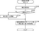
- 6 is a flowchart illustrating an example of a flow of an image correction process performed by the image correction device according to the first embodiment. 6 is a flowchart illustrating an example of a flow of a color correction process performed by the image correction device according to the first embodiment.
- FIG. 9 is a graph for explaining an example of saturation correction according to a common subject.
- 9 is a graph for explaining an example of saturation correction according to a common subject.
- 9 is a graph for explaining an example of saturation correction according to a common subject.
- 6 is a graph for explaining an example of a relationship between a hue angle and a correction amount.
- FIG. 14 is an explanatory diagram for describing an example of a first image and a second image according to the second embodiment.
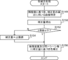
- 13 is a flowchart illustrating another example of the flow of the color correction process according to the second embodiment.
- 15 is a flowchart illustrating another example of the flow of the image correction process according to the third embodiment.
- 6 is a graph for explaining an example of color correction by a user.
- 11 is a graph for explaining color correction according to a third embodiment. It is a top view showing other examples of the composition of the imaging system of an embodiment.
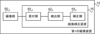
- FIG. 17 is a block diagram illustrating an example of a functional configuration of the first
- obtaining a captured image such as a moving image by capturing an image of an object to be captured by an image capturing apparatus is referred to as capturing. Therefore, “imaging” when the user performs imaging using the imaging device and “imaging” performed by the imaging device may be interchangeable in some cases.
- the imaging system 10 of the present embodiment includes two imaging devices, a first imaging device 12 and a second imaging device 14, and an image correction device 16.
- the first imaging device 12 and the second imaging device 14 of the present embodiment are examples of a plurality of imaging devices of the present disclosure.
- a user takes an image of a person P to be imaged from different directions by using the first imaging device 12 and the second imaging device 14, and the first imaging device 12 and the second imaging device A mode in which moving images obtained by the respective imaging devices 14 are edited and combined to generate one moving image, so-called video content, will be described.
- one person or a plurality of persons who actually operate each of the first imaging device 12 and the second imaging device 14 may be used. Then, they are simply called "users”.
- a moving image captured by the first imaging device 12 is referred to as a “first image”
- a moving image captured by the second imaging device 14 is referred to as a “second image”.
- first image and the “second image” are collectively referred to without distinction, they are referred to as “moving images”.
- FIG. 2 shows an example of a first image D1 captured by the first imaging device 12 and a second image D2 captured by the second imaging device 14.
- the first image D1 includes a person image PG1 of the person P, a sky image SG1 of the sky S, a tree image TG1 of the tree T, and a house image HG1 of the house H.
- the second image D2 includes a person image PG2 of the person P, a sky image SG1 of the sky S, and a tree image TG2 of the tree T.
- the user edits the first image D1 and the second image D2 in chronological order and connects them, thereby combining the first image D1 and the second image D2 with one another.
- a mode for generating two moving images will be described. Specifically, for example, the first image D1 until 3 minutes after the start of shooting of the person P, the second image D2 from 3 minutes to 4 minutes later, and 7 minutes after 4 minutes Up to this point, a case will be described in which the first image D1 and the like, and the first image D1 and the second image D2 are combined in chronological order. Note that the method of combining the first image D1 and the second image D2 is not limited to the present embodiment.
- one screen is divided into two regions, and the first image D1 and the second image are arranged by arranging the first image D1 in one of the divided regions and the second image D2 in the other region. You may combine with D2. Further, one image of the first image D1 and the second image D2 may be combined with the other image so that both images are displayed at the same time.
- Each of the first imaging device 12 and the second imaging device 14 is connected to the image correction device 16 by an HDMI (High-Definition Multimedia Interface) (registered trademark) cable.
- HDMI High-Definition Multimedia Interface
- the connection method between the first imaging device 12 and the second imaging device 14 and the image correction device 16 is not limited to the present embodiment, and other wired connection modes or wireless connection modes may be used. May be performed. Further, the first imaging device 12 and the second imaging device 14 may be connected to the image correction device 16 by different methods. Moving image data representing a moving image captured by each of the first imaging device 12 and the second imaging device 14 is output to the image correction device 16.
- the image correction device 16 approximates the colors of the same scene between the first image D1 captured by the first imaging device 12 and the second image D2 captured by the second imaging device 14. It has a function to perform correction.
- the image correction device 16 of the present embodiment includes a CPU (Central Processing Unit) 20, a memory 21 as a temporary storage area, and a nonvolatile storage unit 22. Further, the image correction device 16 includes a display unit 23 such as a liquid crystal display and an operation unit 24 including various buttons and the like. The display unit 23 and a part of the operation unit 24 are configured as an integrated touch panel display.
- the image correction device 16 includes an external I / F 26 to which the first imaging device 12 and the second imaging device 14 are connected.
- the CPU 20, the memory 21, the storage unit 22, the display unit 23, the operation unit 24, and the external I / F 26 are connected to a bus 29. Examples of the image correction device 16 include a personal computer and a server computer.
- the storage unit 22 is realized by a hard disk drive (HDD), a solid state drive (SSD), a flash memory, and the like.
- An image correction program 30 is stored in the storage unit 22 as a storage medium.
- the CPU 20 reads out the image correction program 30 from the storage unit 22 and then develops it in the memory 21, and executes the developed image correction program 30.
- the image correction device 16 of the present embodiment includes a receiving unit 40, a detection unit 42, and a correction unit 44.
- the CPU 20 executes the image correction program 30, it functions as the receiving unit 40, the detecting unit 42, and the correcting unit 44.
- the receiving unit 40 includes a first image D1 captured by the first imaging device 12, a second image D2 captured by the second imaging device 14, a first image D1, and a second image D2.
- at least one of the information related to the shooting date and time and the information related to the shooting location associated with each moving image is referred to as “shooting condition”.
- the “imaging date and time” may be at least one of the year, month, day, and time at which the user performed imaging using the first imaging device 12 or the second imaging device 14, or
- the information is not limited to the month, day, and time itself, but may be information that can specify them.
- the “shooting place” is not limited to a specific geographical position itself obtained by a position detection sensor such as a GPS (Global Positioning System) sensor, for example.
- the information may be identifiable.
- the detection unit 42 determines the image indicated by the first image D1 and the second image D2 based on the information indicating the imaging condition corresponding to each of the first image D1 and the second image D2 received by the reception unit 40. It has a function of detecting the same scene between each other.
- the correction unit 44 extracts a common subject between the images from each of the images indicated by the first image D1 and the second image D2 corresponding to the same scene detected by the detection unit 42, and It has a function of performing color correction for bringing colors closer to each other for a corresponding image.
- the image correction processing shown in FIG. 5 is executed.
- the image correction processing illustrated in FIG. 5 is executed, for example, when the first imaging device 12 and the second imaging device 14 are connected to the image correction device 16.
- the receiving unit 40 receives moving image data and corresponding shooting conditions from each of the first imaging device 12 and the second imaging device 14. Specifically, the receiving unit 40 receives the first image D1 and the imaging conditions of the first image D1 from the first imaging device 12, and receives the second image D2 and the second image D2 from the second imaging device 14. The photographing condition of the image D2 is received.
- the photographing conditions can be accepted, for example, by obtaining Exif (Exchangeable image file format) information attached to the metadata of each of the first image D1 and the second image D2.
- the detection unit 42 detects the same scene between the first image D1 and the second image D2 based on the imaging conditions received by the reception unit 40.
- the same scene refers to a scene where the first imaging device 12 and the second imaging device 14 are shooting the same shooting target, a scene where the same event is shooting, and
- the user edits the first image D1 and the second image D2 it refers to a scene or the like determined to be combined into one video.
- the method by which the detection unit 42 detects the same scene based on the shooting conditions is not particularly limited, but as an example, in the present embodiment, first, in the present embodiment, the detection unit 42 first determines the first image D1 and the second image D2.
- the same scene is detected in each moving image, and images (frames) included in each moving image are collected for each same scene.
- the detection unit 42 puts together images captured within a predetermined time as images of the same scene. Further, the detection unit 42 determines, for the first image D1 and the second image D2, an image group in which the difference in the shooting date and time is within the threshold and the difference in the shooting location is within the threshold among the images grouped as the same scene. The groups are detected as the same scene.
- both the shooting date and time and the shooting location may be used, or only one of them may be used.
- There is no particular limitation on which one is used to detect the same scene and for example, a predetermined form or a form that can be set by the user may be used.
- the method of detecting the same scene is not limited to the detection method of the present embodiment. For example, information other than the shooting date and time and the shooting location may be used, and information indicating that the same scene is input by the user in shooting. May be detected.
- step S104 the detection unit 42 determines whether the same scene has been detected between the first image D1 and the second image D2. If the same scene is not detected, the determination in step S104 is negative, and the image correction processing ends. On the other hand, when the same scene is detected, the determination in step S104 is affirmative, and the process proceeds to step S106.
- step S106 the detection unit 42 associates the same detected scene between the first image D1 and the second image D2.
- the method by which the detection unit 42 associates the same scene with each other is not particularly limited. For example, a mode in which the same identifier is assigned to each scene may be used.
- the correction unit 44 extracts a subject (hereinafter, referred to as a “common subject”) that is commonly included in each image for each identical scene between the first image D1 and the second image D2.
- a subject hereinafter, referred to as a “common subject”
- the first image D1 includes the person image PG1, the sky image SG1, and the tree image TG1
- the second image D2 Includes the person image PG2, the sky image SG2, and the tree image TG2, and the subjects commonly included in both images are the face P1, the sky S, and the tree T of the person P.
- the correction unit 44 extracts at least one of the person P, the sky S, and the tree T as a common subject.
- the number of common subjects extracted by the correction unit 44 may be one or more, and the number of common subjects may be in a predetermined form.
- the setting may be possible.
- an upper limit value may be set from the viewpoint of avoiding complicated processing.
- a specific subject such as the set person P may be extracted as a common subject in accordance with an instruction and setting by a user or the like.
- the method by which the correction unit 44 extracts the common subject from the image is not particularly limited, and a method according to each subject can be applied.
- the face P1 of the person P is set as a common subject
- the face of the same person may be extracted as a common subject by applying existing face detection technology and face authentication technology to the image.
- an existing object recognition technique for judging an image based on color, resolution, contrast, angle of view, and the like is applied, and the same is applied. May be extracted as a common subject.
- an existing technique for making a determination based on an area in the image specifically, an upper area), a color, or the like, or a horizon is detected, and determination is made based on a position based on the horizon. It is sufficient to extract a subject such as the sky as a common subject by applying an existing technique for performing the above.
- the correction unit 44 performs a color correction process, an example of which is shown in FIG. 6, to correct the color of the common subject in the same scene between the first image D1 and the second image D2.
- a color correction process illustrated in FIG. 6, one image of the same scene between the first image D1 and the second image D2 is to be corrected, and the same scene detected by the detection unit 42 is used for each of the same scenes.
- the color correction process is repeated for the number of times corresponding to the same scene.
- the first imaging device 12 is a main camera mainly used by a user for imaging of an imaging target
- the second imaging device 14 is a sub-camera. An embodiment in which the color of the second image D2 obtained by the second imaging device 14 is made closer to the first image D1 obtained by the imaging device 12 will be described.
- step S150 in FIG. 6 the correction unit 44 derives a correction amount.
- the method of deriving the correction amount is not particularly limited, but includes, for example, the following derivation methods.
- the correction unit 44 determines the colors of the person image PG1 included in the first image D1 and the person image PG2 included in the second image D2. Color correction is performed so as to make the colors closer to each other and make the difference between the colors less than or equal to the threshold, and more preferably to make the colors the same. As an example, in the present embodiment, correction is performed to match the color of the person image PG2 with the color of the person image PG1.
- the correction unit 44 adjusts the white balance of the person image PG2 to shift the color to approximate the color of the person image PG1, and adjusts the saturation gain (magnification) to increase the saturation of the person image PG1. Perform the process of approaching. Therefore, the correction unit 44 derives the color shift amount and the saturation magnification as correction amounts.
- the correction unit 44 adds the person image PG1 included in the image of the first image D1 and the image of the second image D2.
- the color correction is performed such that the color tone of the included person image PG2 is made close to the color image so that the color difference is within the threshold value, more preferably, the color tone is the same.
- the correction unit 44 brings the color of the sky image SG1 included in the image of the first image D1 and the color of the sky image SG2 included in the image of the second image D2 closer to each other, and sets the difference in the color to within a threshold value. And more preferably, color correction for making the colors the same. Further, the correction unit 44 makes the color of the tree image TG1 included in the image of the first image D1 and the color of the tree image TG2 included in the image of the second image D2 close to each other so that the color difference is within the threshold value. And more preferably, color correction for making the colors the same. As an example, as shown in FIG.
- each of the person image PG1, the sky image SG1, and the tree image TG1 of the first image D1, and the person image PG1, the sky image SG2, and the tree image TG2 of the second image D2 are each shown.
- FIG. 8 shows an example in which the saturation of the second image D2 is corrected based on the face P1 of the person P, which is a common subject.
- the correction unit 44 derives a correction amount (magnification) for matching the saturation of the person image PG2 with the saturation of the person image PG1, and uses the derived correction amount to generate another common object. Is also corrected.
- the saturation of the person image PG1 and the saturation of the person image PG2 are matched for the above, the saturation of the sky image SG1 and the saturation of the sky image SG2 are close to each other.
- the saturation of the tree image TG1 and the saturation of the tree image TG2 are close to each other, but do not match.
- the saturation of a single common subject when used as a reference, the saturation of another common subject may not always match, but the difference in chromaticity is within a predetermined range. If it is inside. If the chromaticity difference does not fall within the predetermined range, for example, the reference common subject may be changed.
- the saturation may be corrected to a state where the difference in chromaticity is within a predetermined range for all common subjects without providing a common subject as a reference.
- the color white The shift amount of (balance) may be corrected.
- the tint adjustment accuracy can be increased as compared with the case where the correction amount is derived using a single common subject. .
- the correction unit 44 derives a correction amount for approximating the saturation for each of the face P1, the sky S, and the tree T of the person P, which is a common subject.
- FIG. 9 shows an example in which a correction amount is derived for each common subject and the saturation of the second image D2 is corrected. In the embodiment shown in FIG. 9, it can be seen that the difference in saturation for all common subjects is smaller than in the embodiment shown in FIG. 8.
- the correction unit 44 further derives a hue (a correction amount for each hue angle based on the correction amount derived for each common subject.
- the hue angle is calculated in the second image D2. 11 is a graph showing an example of the relationship between the hue angle, which is the horizontal axis of the graph shown in FIG. The case where the angle is set to 0 degree is shown, and when the correction amount is 1 (times), it indicates that the correction does not need to be performed. Interpolation is performed so as to smoothly connect between the correction amounts of the face P1, the sky S, and the tree T of the person P, and a correction amount corresponding to the hue angle is derived. In the example shown in FIG. 10, only the correction of the saturation has been described.
- the shift amount of the tint may be corrected in the same manner as in the case of a single common subject described above.
- the color of the entire image can be made closer to that in the case where the correction is performed using a single correction amount for all hues.
- step S152 the correction unit 44 determines whether the derived correction amount is equal to or less than a predetermined upper limit. Note that, when a plurality of common subjects are detected, it is preferable to perform this determination for each common subject, and an upper limit value is determined according to the type of the common subject, for example, a person, an object, and a background. Is also good. If the correction amount exceeds the upper limit, the determination in step S152 is negative, and the process proceeds to step S154. In step S154, the correction unit 44 sets the correction amount to the upper limit instead of the derived correction amount, and then proceeds to step S156.
- step S152 determines whether the correction amount is equal to or smaller than the upper limit. If the correction amount is equal to or smaller than the upper limit, the determination in step S152 is affirmative, and the process proceeds to step S156.
- step S156 the correction unit 44 performs the color correction based on the correction amount for each image included in the same scene for each of the imaging device and the same scene, and ends the color correction processing. When the color correction processing is completed in this way, the process proceeds to step S112 of the image correction processing (see FIG. 5).
- step S112 the correction unit 44 stores the first image D1 and the second image D2 after color correction in the storage unit 22, and then ends the image correction processing.
- the first image D1 and the second image D2 after color correction may be displayed on the display unit 23, or may be transmitted to an external device via the external I / F 26 as desired by the user. May be output.
- the configurations of the imaging system 10 and the image correction device 16 of the present embodiment are the same as the configurations of the imaging system 10 and the image correction device 16 of the first embodiment (see FIGS. 1, 3, and 4), and thus will be described. Is omitted.
- the operation of the image correction device 16 of the present embodiment is different in a part of the color correction processing executed in the image correction processing.
- the detection unit 42 detects and associates the same scene between the first image D1 and the second image D2.
- the brightness values (exposure) of the images of the image group determined to be the same scene in the first image D1 are different.
- the brightness values of the images of the image group determined to be the same scene in the second image D2 are different.
- the first image D1 and the second image D2 associated with the same scene by the detection unit 42 each include three images (frames).
- the first image D1 includes an image F11, an image F12, and an image F13.
- the luminance value of the image F12 is higher than the luminance value of the image F11
- the image F13 is higher than the luminance value of the image F11.
- the second image D2 includes an image F21, an image F22, and an image F23.
- the luminance value of the image F23 is higher than the luminance value of the image F22.
- the brightness value of the image F21 is low. In the example shown in FIG.
- the image F13 of the image D1 and the image F21 of the second image D2 have a combination in which the luminance values are close to each other (for example, the difference between the luminance values is within a predetermined threshold).
- the saturation varies even for the same subject.
- the saturation decreases.
- the saturation increases. In other words, the saturation may be different even for the same imaging device, the same scene, and the same subject.
- the first image D1 and the second image D2 are corrected so that the colors of the common subject extracted from the images having similar luminance values are brought close to each other. Reduces the effect of differences in saturation due to differences in
- FIG. 12 is a flowchart illustrating an example of the flow of the color correction process according to the present embodiment. As shown in FIG. 12, in the color correction process of the present embodiment, the process of step S149 is performed before step S150 of the color correction process of the first embodiment (see FIG. 6) and immediately after the start of the color correction process. The points are different.
- the correction unit 44 specifies an image used to derive a correction amount from the first image D1 and the second image D2 based on the luminance value of each image.
- the correction unit 44 includes the image F11 of the first image D1, the image F22 of the second image D2, the image F12 of the first image D1, and the second image One of the image F23 of D2, the image F13 of the first image D1, and the image F21 of the second image D2 is specified. Note that when correcting the color tone, it is preferable that the luminance value of the image is not too high (not too over) and the luminance value is not too low (not too under).
- the range of the luminance value applied to the image used to derive the correction amount is determined in advance, and the correction unit 44 determines that the image is within the determined range and that the luminance value is A combination of images having a small difference is specified as an image used for deriving a correction amount.
- the correction unit 44 may specify an image used to derive a correction amount for each common subject.
- the image F11 of the first image D1 and the image F22 of the second image D2 are specified for the face P1 of the person P, and the image F22 of the second image D2 is specified for the sky S.
- the image F12 of the first image D1 and the image F23 of the second image D2 may be specified, and for the tree T, the image F13 of the first image D1 and the image F21 of the second image D2 may be specified. .
- the correction amount is derived from the specified image as described above.
- the image correction device 16 of the present embodiment derives the correction amount used for color correction from an image having a relatively close luminance value, so that color correction can be performed with higher accuracy.
- the configurations of the imaging system 10 and the image correction device 16 of the present embodiment are the same as the configurations of the imaging system 10 and the image correction device 16 of the first embodiment (see FIGS. 1, 3, and 4), and thus will be described. Is omitted.
- the operation of the image correction device 16 of the present embodiment is different in part of the image correction processing.
- the color correction performed by the image correction device 16 in the image correction process is a color correction for approximating the colors of the same scene between the first image D1 and the second image D2.
- a description will be given of a mode in which a user performs color correction by so-called post-production.
- FIG. 13 is a flowchart illustrating an example of the flow of the image correction process according to the present embodiment. As shown in FIG. 13, in the image correction processing of the present embodiment, each processing of steps S111A and S111B is performed between steps S110 and S112 of the image correction processing of the first embodiment (see FIG. 5). Are different.
- step S111A the correction unit 44 determines whether the user has performed color correction as post-production, that is, the user refers to at least one of the first image D1 and the second image D2 displayed on the display unit 23. Then, it is determined whether or not the color correction has been performed by the operation unit 24.
- the color correction performed in step S110 according to the present embodiment is an example of the first color correction according to the present disclosure
- the color correction performed by the user in post-production according to the present embodiment is the second color correction according to the present disclosure. It is an example of correction.
- step S110 After the process of step S110 is completed, for example, in the present embodiment, even if a predetermined period elapses, if there is no operation of the operation unit 24 by the user, and the image correction process is performed via the operation unit 24, Has been instructed by the user, the determination in step S111A is negative, and the process proceeds to step S112. On the other hand, when the user performs color correction using the operation unit 24, the determination in step S111A is affirmative, and the process proceeds to step S111B.
- FIG. 14 shows an example of color correction performed by the user in post-production. The example illustrated in FIG. 14 illustrates a state in which the saturation of the entire first image D1 has been corrected. In other words, the case where the saturation of the image of the first image D1 is shifted as a whole is shown.
- the correction unit 44 performs the same color correction on all the images of the same scene as the image on which the color correction has been performed by the user.
- the correction unit 44 performs the color correction.
- the first image D1 of the same scene as the image is similarly shifted in saturation as color correction.
- all the second images D2 associated with the same scene as the first image D1 whose saturation has been shifted are similarly subjected to color correction as color correction. Perform a degree shift.
- the image correction device 16 of the present embodiment reduces the difference between the first image D1 and the second image D2, that is, the difference between the first imaging device 12 and the second imaging device 14.
- the color correction that reflects the post-production of the color correction by the user is automatically performed. Therefore, according to the image correction device 16 of the present embodiment, the user does not need to perform the color correction on both the first image D1 and the second image D2, which is troublesome for the user. Can be simplified.
- the image correction device 16 of each of the above embodiments includes the reception unit 40, the detection unit 42, and the correction unit 44.
- the receiving unit 40 includes a first image D1 and a second image D2 obtained by imaging by each of the first imaging device 12 and the second imaging device 14, and a first image D1 and a second image D2. And the imaging condition corresponding to at least one of the information on the imaging date and the information on the imaging location corresponding to each of the imaging conditions.
- the detecting unit 42 determines the same between the images indicated by the first image D1 and the second image D2 based on the shooting conditions corresponding to each of the first image D1 and the second image D2 received by the receiving unit 40. Is detected.
- the correction unit 44 extracts a common subject common between the images from each of the images indicated by the first image D1 and the second image D2 corresponding to the same scene detected by the detection unit 42, and The color correction that brings the color of the subject closer is performed on the corresponding image.
- the image correction device 16 of the present embodiment it is possible to reduce a difference in color between moving images obtained by each of the plurality of imaging devices. Therefore, when the first image D1 and the second image D2 of the same scene are combined and edited into one moving image, a natural moving image with a sense of unity can be obtained.
- the image correction device 16 automatically performs color correction for each same scene without requiring post-production by the user, so that the user can save time and effort, and is a user unfamiliar with shooting. Even so, it is possible to easily edit a moving image with a sense of unity.
- the mode in which the color of the second image D2 is matched with the color of the first image D1 is described.
- the color of the second image D2 may be changed.
- the color of the first image D1 may be adjusted to the color of the first image D1 or the color of the first image D1 and the color of the second image D2 to a predetermined color such as a color desired by the user. May be combined. Further, when a plurality of common subjects are extracted, it may be set for each common subject which color to match.
- the imaging system 10 has been described in which the imaging device (the first imaging device 12 and the second imaging device 14) and the image correction device 16 are provided as separate devices. It is not limited to the form. For example, any of the imaging devices may have the function of the image correction device 16.
- FIG. 16 shows an example of the configuration of the imaging system 10 in this case.
- the imaging system 10 shown in FIG. 16 an embodiment in which the first imaging device 12 has the function of the image correction device 16 is shown.
- FIG. 17 is a block diagram showing an example of a functional configuration of the first imaging device 12 shown in FIG. As illustrated in FIG. 17, the first imaging device 12 includes an imaging unit 50 and the image correction device 16 including a reception unit 40, a detection unit 42, and a correction unit 44.
- the detection unit 42 and the correction unit 44 have the same functions as those in the above-described embodiments, and a description thereof is omitted.
- the imaging unit 50 illustrated in FIG. 17 has a function of capturing a first image D1 that is a moving image of a subject and outputting moving image data of the first image D1 obtained by the imaging.
- the reception unit 40 includes a first image D1 (moving image data) output from the imaging unit 50, a second image D2 captured by the second imaging device 14, a first image D1, and a second image D1. And at least one of the information on the shooting date and time and the information on the shooting location corresponding to each of the two images D2.
- the present invention is not limited to the embodiments shown in FIGS. 16 and 17.
- the image correction device 16 may have an imaging function such as including the imaging unit 50.
- the hardware structure of a processing unit that executes various processes includes the following various processors: Can be used.
- the CPU which is a general-purpose processor that executes software (program) and functions as various processing units
- the above-described various processors include a circuit after manufacturing an FPGA (Field Programmable Gate Array) or the like.
- Dedicated electricity which is a processor having a circuit configuration specifically designed to execute a specific process such as a programmable logic device (PLD) or an ASIC (Application Specific Integrated Circuit), which is a processor whose configuration can be changed. Circuit etc. are included.
- One processing unit may be constituted by one of these various processors, or a combination of two or more processors of the same type or different types (for example, a combination of a plurality of FPGAs or a combination of a CPU and an FPGA). Combination). Further, a plurality of processing units may be configured by one processor. As an example in which a plurality of processing units are configured by one processor, first, as represented by computers such as a client and a server, one processor is configured by a combination of one or more CPUs and software. There is a form in which the processor functions as a plurality of processing units.
- SoC system-on-chip
- a form using a processor that realizes the functions of the entire system including a plurality of processing units by one IC (Integrated Circuit) chip is used.
- the various processing units are configured by using one or more of the various processors described above as a hardware structure.
- circuitry in which circuit elements such as semiconductor elements are combined can be used.
- the image correction program 30 is provided in a form recorded on a recording medium such as a CD-ROM (Compact Disk Read Only Memory), a DVD-ROM (Digital Versatile Disk Read Only Memory), and a USB (Universal Serial Bus) memory. Is also good. Further, the image correction program 30 may be downloaded from an external device via a network.
- a recording medium such as a CD-ROM (Compact Disk Read Only Memory), a DVD-ROM (Digital Versatile Disk Read Only Memory), and a USB (Universal Serial Bus) memory. Is also good.
- the image correction program 30 may be downloaded from an external device via a network.
- Imaging system 10 Imaging system 12 First imaging device 14 Second imaging device 16 Image correction device 20 CPU 21 memory 22 Memory 23 Display 24 Operation unit 26 External I / F 29 bus 30 Image correction program 40 Reception desk 42 Detector 44 Correction unit 50 Imaging unit D1 First image D2 Second image F11, F12, F13, F21, F22, F23 Image (frame) P person P1 face PG1, PG2 person image H house HG1, HG2 house image S sky SG1, SG2 sky image T tree TG1, TG2 Tree image
Landscapes
- Engineering & Computer Science (AREA)
- Multimedia (AREA)
- Signal Processing (AREA)
- Computing Systems (AREA)
- Theoretical Computer Science (AREA)
- Image Processing (AREA)
- Processing Of Color Television Signals (AREA)
Abstract
複数の撮像装置の各々による撮像により得られた動画像間の色味の差異を低減することができる画像補正装置、撮像装置、画像補正方法、及び画像補正プログラムを提供する。画像補正装置16の受付部40は、第1の撮像装置12及び第2の撮像装置14の各々により得られた第1の画像D1及び第2の画像D2と、第1の画像D1及び第2の画像D2の各々に対応する撮像日時に関する情報、及び撮像場所に関する情報の少なくとも一方の情報である撮影条件とを受け付ける。検出部42は、第1の画像D1及び第2の画像D2の各々に対応する撮影条件に基づいて第1の画像D1及び第2の画像D2が示す画像間における同一のシーンを検出する。補正部44は、同一のシーンに対応する第1の画像D1及び第2の画像D2が示す画像の各々から画像の間で共通する共通被写体を抽出し、抽出した共通被写体の色を近づける色補正を対応する画像に対して行う。
Description
本開示の技術は、画像補正装置、撮像装置、画像補正方法、及び画像補正プログラムに関する。
従来、ユーザが共通の撮影対象を複数の撮像装置の各々により撮影する場合に、各撮像装置による撮像により得られた動画像を1つの動画像にまとめることが一般的に行われている。例えば、特許文献1には、動画像コンテンツに関連付けられている撮影時刻及び空間情報に基づいて、複数の動画像コンテンツの中から再生対象のコンテンツを選択することで、関連する動画像コンテンツをまとめて再生する技術が記載されている。
ところで、上記のように、複数の撮像装置各々による撮像により得られた動画像を1つの動画像にまとめる場合、各撮像装置の撮像方向が異なったり、各撮像装置の機種及び撮像年代が異なったりする場合、各撮像装置による撮像により得られた動画像間の色味の差異が比較的大きくなってしまう。この結果、各撮像装置による撮像により得られた動画像をまとめることによって得られた1つの動画像は、映像に統一感のない動画像になってしまう場合があった。
本開示は、上記事情を考慮して成されたものであり、複数の撮像装置の各々による撮像により得られた動画像間の色味の差異を低減することができる、画像補正装置、撮像装置、画像補正方法、及び画像補正プログラムを提供することを目的とする。
上記目的を達成するために、本開示の第1の態様の画像補正装置は、複数の撮像装置の各々による撮像により得られた複数の動画像データと、複数の動画像データの各々に対応する撮像日時に関する情報、及び撮像場所に関する情報の少なくとも一方の情報とを受け付ける受付部と、受付部が受け付けた複数の動画像データの各々に対応する少なくとも一方の情報に基づいて、複数の動画像データが示す画像間における同一のシーンを検出する検出部と、検出部が検出した同一のシーンに対応する複数の動画像データが示す画像の各々から、画像の間で共通する被写体を抽出し、抽出した被写体の色を近づける色補正を、対応する画像に対して行う補正部と、を備える。
第2の態様の画像補正装置は、第1の態様の画像補正装置において、補正部は、被写体を複数抽出した場合、複数の被写体の全てについて、被写体の色を全体として近付けるための色補正を行う。
第3の態様の画像補正装置は、第1の態様または第2の態様の画像補正装置において、補正部は、抽出した被写体の彩度を、色相依存で近付けることにより、色補正を行う。
第4の態様の画像補正装置は、第1の態様から第3の態様のいずれか1態様の画像補正装置において、補正部は、同一のシーンに対応する複数の動画像データが示す画像の各々のうち、抽出した被写体の輝度値が同じとみなせる画像同士により、色補正に用いる補正量を導出する。
第5の態様の画像補正装置は、第4の態様の画像補正装置において、補正部は、被写体を複数抽出した場合、被写体毎に、被写体の輝度値が同じとみなせる画像同士により、色補正に用いる補正量を導出する。
第6の態様の画像補正装置は、第1の態様から第5の態様のいずれか1態様の画像補正装置において、補正部は、色補正を第1の色補正を行った後、さらに、複数の動画像データのうちの1つの動画像データが示す画像に対して第1の色補正と異なる第2の色補正を行った場合、複数の動画像データのうちの他の動画像データが示す画像に対しても、第2の色補正を行う。
第7の態様の画像補正装置は、第1の態様から第6の態様のいずれか1態様の画像補正装置において、被写体の種類に応じて、色補正の補正量の上限が予め定められている。
第8の態様の撮像装置は、被写体の動画像を撮像し、撮像により得られた動画像データを出力する撮像部と、撮像部から出力された動画像データ、及び他の撮像装置による撮像により得られた動画像データを含む複数の動画像データと、複数の動画像データの各々に対応する撮像日時に関する情報、及び撮像場所に関する情報の少なくとも一方の情報とを受け付ける受付部と、受付部が受け付けた複数の動画像データの各々に対応する少なくとも一方の情報に基づいて、複数の動画像データが示す画像間における同一のシーンを検出する検出部と、検出部が検出した同一のシーンに対応する複数の動画像データが示す画像の各々から、画像の間で共通する被写体を抽出し、抽出した被写体の色を近づける色補正を、対応する画像に対して行う補正部と、を備える。
第9の態様の画像補正方法は、複数の撮像装置の各々による撮像により得られた複数の動画像データと、複数の動画像データの各々に対応する撮像日時に関する情報、及び撮像場所に関する情報の少なくとも一方の情報とを受け付け、受け付けた複数の動画像データの各々に対応する少なくとも一方の情報に基づいて、複数の動画像データが示す画像間における同一のシーンを検出し、検出した同一のシーンに対応する複数の動画像データが示す画像の各々から、画像の間で共通する被写体を抽出し、抽出した被写体の色を近づける色補正を、対応する画像に対して行う、処理をコンピュータが実行する方法である。
第10の態様の画像補正プログラムは、複数の撮像装置の各々による撮像により得られた複数の動画像データと、複数の動画像データの各々に対応する撮像日時に関する情報、及び撮像場所に関する情報の少なくとも一方の情報とを受け付け、受け付けた複数の動画像データの各々に対応する少なくとも一方の情報に基づいて、複数の動画像データが示す画像間における同一のシーンを検出し、検出した同一のシーンに対応する複数の動画像データが示す画像の各々から、画像の間で共通する被写体を抽出し、抽出した被写体の色を近づける色補正を、対応する画像に対して行う、処理をコンピュータに実行させるためのものである。
また、上記目的を達成するために、本開示の画像補正装置は、プロセッサを有する画像補正装置であって、プロセッサが、複数の撮像装置の各々による撮像により得られた複数の動画像データと、複数の動画像データの各々に対応する撮像日時に関する情報、及び撮像場所に関する情報の少なくとも一方の情報とを受け付け、受け付けた複数の動画像データの各々に対応する少なくとも一方の情報に基づいて、複数の動画像データが示す画像間における同一のシーンを検出し、検出した同一のシーンに対応する複数の動画像データが示す画像の各々から、画像の間で共通する被写体を抽出し、抽出した被写体の色を近づける色補正を、対応する画像に対して行う、画像補正装置である。
本開示によれば、複数の撮像装置の各々による撮像により得られた動画像間の色味の差異を低減することができる。
以下、図面を参照して本開示の技術を実施するための形態例を詳細に説明する。なお、以下では、ユーザが撮影対象を、撮像装置により撮像して動画像等の撮像画像を得ることを、撮影という。そのため、ユーザが撮像装置を用いて撮影を行う場合の「撮影」と、撮像装置による「撮像」とは、置き換えが可能な場合がある。
[第1実施形態]
まず、図1を参照して、本実施形態の撮像システム10の構成を説明する。図1に示すように、本実施形態の撮像システム10は、第1の撮像装置12及び第2の撮像装置14の2台の撮像装置と、画像補正装置16と、を備える。本実施形態の第1の撮像装置12及び第2の撮像装置14が、本開示の複数の撮像装置の一例である。
本実施形態では、一例として、ユーザが、第1の撮像装置12と、第2の撮像装置14とにより、異なる方向から撮影対象である人物Pを撮影し、第1の撮像装置12及び第2の撮像装置14の各々により得られた動画像を編集し、組み合わせて1つの動画像、いわゆる映像コンテンツを生成する形態について説明する。なお、人物Pの撮影において、実際に第1の撮像装置12及び第2の撮像装置14の各々を操作する人物は一人であってもよいし、複数人であってもよいが、本実施形態では、総称して単に「ユーザ」という。また、以下では、第1の撮像装置12により撮像された動画像を「第1の画像」といい、第2の撮像装置14により撮影された動画像を「第2の画像」という。また、「第1の画像」及び「第2の画像」の各々を区別せずに総称する場合、「動画像」という。
図2には、第1の撮像装置12により撮影された第1の画像D1、及び第2の撮像装置14により撮影された第2の画像D2の一例を示す。第1の画像D1には、人物Pの人物画像PG1、空Sの空画像SG1、樹木Tの樹木画像TG1、及び家屋Hの家屋画像HG1が含まれている。また、第2の画像D2には、人物Pの人物画像PG2、空Sの空画像SG1、及び樹木Tの樹木画像TG2が含まれている。
本実施形態では、一例として、ユーザが、時系列順に第1の画像D1と第2の画像D2とを編集し、つなげることにより、第1の画像D1と第2の画像D2とを組み合わせて1つの動画像を生成する形態について説明する。具体的には、例えば、人物Pの撮影を開始してから3分後までは第1の画像D1、3分後から4分後までは第2の画像D2、及び4分後から7分後までは第1の画像D1等と、第1の画像D1と第2の画像D2とを時系列順に組み合わせる場合について説明する。なお、第1の画像D1と第2の画像D2との組み合わせ方は本実施形態に限定されない。例えば、1つの画面を2つの領域に分割し、分割した一方の領域に第1の画像D1を、他方の領域に第2の画像D2を配置することで第1の画像D1と第2の画像D2とを組み合わせてもよい。また、第1の画像D1及び第2の画像D2の一方の画像中に、他方の画像を組み合わせ、同時に両方の画像が表示される形態として組み合わせてもよい。
第1の撮像装置12及び第2の撮像装置14の各々は、HDMI(High-Definition Multimedia Interface)(登録商標)ケーブルによって画像補正装置16に接続される。なお、第1の撮像装置12及び第2の撮像装置14と、画像補正装置16との接続方法は本実施形態に限定されず、その他の有線接続を行う形態であってもよいし、無線接続を行う形態であってもよい。また、第1の撮像装置12及び第2の撮像装置14の各々が異なる方法により、画像補正装置16と接続を行う形態であってもよい。第1の撮像装置12及び第2の撮像装置14の各々により撮像された動画像を表す動画像データは、画像補正装置16に出力される。
画像補正装置16は、第1の撮像装置12により撮影された第1の画像D1と、第2の撮像装置14により撮影された第2の画像D2とにおける、同一のシーンについて、色味を近づける補正を行う機能を有する。
図3を参照して、本実施形態の画像補正装置16のハードウェア構成を説明する。図3に示すように、本実施形態の画像補正装置16は、CPU(Central Processing Unit)20、一時記憶領域としてのメモリ21、及び不揮発性の記憶部22を含む。また、画像補正装置16は、液晶ディスプレイ等の表示部23、及び各種ボタン等を含む操作部24を含む。なお、表示部23と、操作部24の一部とは一体化されたタッチパネルディスプレイとして構成されている。また、画像補正装置16は、第1の撮像装置12及び第2の撮像装置14が接続される外部I/F26を含む。CPU20、メモリ21、記憶部22、表示部23、操作部24、及び外部I/F26は、バス29に接続される。画像補正装置16の例としては、パーソナルコンピュータ及びサーバコンピュータ等が挙げられる。
記憶部22は、HDD(Hard Disk Drive)、SSD(Solid State Drive)、及びフラッシュメモリ等によって実現される。記憶媒体としての記憶部22には、画像補正プログラム30が記憶される。CPU20は、記憶部22から画像補正プログラム30を読み出してからメモリ21に展開し、展開した画像補正プログラム30を実行する。
次に、図4を参照して、本実施形態の画像補正装置16の機能的な構成について説明する。図4に示すように、本実施形態の画像補正装置16は、受付部40、検出部42、及び補正部44を備える。CPU20が画像補正プログラム30を実行することで、受付部40、検出部42、及び補正部44として機能する。
受付部40は、第1の撮像装置12で撮像された第1の画像D1と、第2の撮像装置14で撮像された第2の画像D2と、第1の画像D1及び第2の画像D2の各々に対応する撮影日時に関する情報、及び撮影場所に関する情報の少なくとも一方の情報とを受け付ける機能を有する。なお、本実施形態では、動画像の各々に対応付けられている、撮影日時に関する情報、及び撮影場所に関する情報の少なくとも一方を、「撮影条件」という。なお、「撮影日時」とは、ユーザが第1の撮像装置12または第2の撮像装置14により撮影を行った年、月、日、及び時刻の少なくとも一つであってもよいし、年、月、日、及び時刻そのものに限定されず、これらを特定可能な情報であってもよい。また、「撮影場所」とは、例えば、GPS(Global Positioning System)センサ等の位置検出センサにより得られる具体的な地理的位置そのものに限定されず、撮影場所の名称等のその他の、撮影場所を特定可能な情報であってもよい。
検出部42は、受付部40が受け付けた第1の画像D1及び第2の画像D2の各々に対応する撮影条件を表す情報に基づいて、第1の画像D1及び第2の画像D2が示す画像同士における同一のシーンを検出する機能を有する。
補正部44は、検出部42が検出した同一のシーンに対応する第1の画像D1及び第2の画像D2が示す画像の各々から、画像の間で共通する被写体を抽出し、抽出した被写体の色を近づける色補正を、対応する画像に対して行う機能を有する。
次に、図5を参照して、本実施形態の画像補正装置16の作用を説明する。CPU20が画像補正プログラム30を実行することによって、図5に示す画像補正処理が実行される。図5に示す画像補正処理は、例えば、第1の撮像装置12及び第2の撮像装置14が画像補正装置16に接続された場合に実行される。
図5のステップS100で、受付部40は、第1の撮像装置12及び第2の撮像装置14の各々から、動画像データと、対応する撮影条件とを受け付ける。具体的には、受付部40は、第1の撮像装置12から第1の画像D1及び第1の画像D1の撮影条件を受け付け、第2の撮像装置14から第2の画像D2及び第2の画像D2の撮影条件を受け付ける。撮影条件は、例えば、第1の画像D1及び第2の画像D2各々のメタデータに付随するExif(Exchangeable image file format)情報を得ることにより、受け付けることができる。
次のステップS102で検出部42は、受付部40が受け付けた撮影条件に基づいて、第1の画像D1及び第2の画像D2間における同一のシーンを検出する。なお、本実施形態において「同一のシーン」とは、第1の撮像装置12及び第2の撮像装置14により同一の撮影対象を撮影している場面、同一の出来事を撮影している場面、及びユーザが第1の画像D1及び第2の画像D2を編集する場合に一つの映像としてまとめると定めた場面等をいう。検出部42が、撮影条件に基づき、同一のシーンを検出する方法は特に限定されないが、一例として、本実施形態では、まず、検出部42は、第1の画像D1及び第2の画像D2の各々において、各動画像内において、同一のシーンを検出し、同一のシーン毎に、各動画像に含まれる画像(フレーム)をまとめる。例えば、検出部42は、第1の画像D1及び第2の画像D2の各々において、所定の時間内に撮影された画像を、同一のシーンの画像としてまとめる。さらに、検出部42は、第1の画像D1及び第2の画像D2について、同一のシーンとしてまとめた画像群のうち、撮影日時の差が閾値以内、及び撮影場所の差が閾値以内である画像群同士を同一のシーンとして検出する。
なお、同一シーンの検出には、撮影日時及び撮影場所の両方を用いてもよいし、いずれか一方のみを用いてもよい。同一のシーンの検出にいずれを用いるかについては、特に限定されず、例えば、予め定められている形態としてもよいし、ユーザにより設定が可能な形態であってもよい。同一のシーンの検出方法は本実施形態の検出方法に限定されず、例えば、撮影日時及び撮影場所以外の情報を用いる形態としてもよく、撮影においてユーザが入力した同一のシーンであることを示す情報を検出する形態としてもよい。
次のステップS104で検出部42は、第1の画像D1及び第2の画像D2の間で同一のシーンが検出されたか否かを判定する。同一のシーンが検出されなかった場合、ステップS104の判定が否定判定となり、本画像補正処理を終了する。一方、同一のシーンが検出された場合、ステップS104の判定が肯定判定となり、ステップS106へ移行する。
ステップS106で検出部42は、第1の画像D1及び第2の画像D2間における検出した同一のシーン同士を対応付ける。検出部42が同一のシーン同士を対応付ける方法は特に限定されず、例えば、シーン毎に、同一の識別子を付与する等の形態としてもよい。
次のステップS108で補正部44は、第1の画像D1及び第2の画像D2間における同一のシーン毎に、各画像に共通して含まれる被写体(以下、「共通被写体」という)を抽出する。例えば、図2に示した第1の画像D1及び第2の画像D2の場合、第1の画像D1には、人物画像PG1、空画像SG1、及び樹木画像TG1が含まれ、第2の画像D2には、人物画像PG2、空画像SG2、及び樹木画像TG2が含まれるため、両画像に共通して含まれる被写体は、人物Pの顔P1、空S、及び樹木Tである。この場合、補正部44は、人物P、空S、及び樹木Tの少なくとも一つを共通被写体として抽出する。なお、補正部44が、抽出する共通被写体の数は、1つであってもよいし、複数であってもよく、共通被写体の数は、予め定められている形態としてもよいし、ユーザにより設定が可能な形態であってもよい。また、抽出する共通被写体の数を複数とする場合、処理が煩雑になるのを避けるため等の観点から上限値を定めておいてもよい。また、ユーザ等の指示及び設定に応じて、設定された人物P等の特定の被写体を共通被写体として抽出する形態としてもよい。
なお、補正部44が、画像から共通被写体を抽出する方法は特に限定されず、各被写体に応じた方法を適用することができる。例えば、人物Pの顔P1を共通被写体とする場合、画像に対して、既存の顔検出技術、及び顔認証技術を適用し、同一人物の顔を共通被写体として抽出すればよい。また例えば、樹木Tや家屋H等の物体(オブジェクト)を共通被写体とする場合、画像に対して、色、解像度、コントラスト、及び画角等から判断を行う既存のオブジェクト認識技術を適用し、同一の物体を共通被写体として抽出すればよい。また例えば、空Sを共通被写体とする場合、画像における領域(具体例として、上側の領域)、及び色等から判断を行う既存の技術や、地平線を検出し、地平線を基準とした位置で判断を行う既存の技術を適用して、空等の被写体を共通被写体として抽出すればよい。
次のステップS110で補正部44は、図6に一例を示す色補正処理を行って、第1の画像D1及び第2の画像D2間の同一シーンにおける共通被写体の色味を補正する。なお、図6に一例を示す色補正処理は、第1の画像D1及び第2の画像D2間の1つの同一シーンの画像が補正の対象であり、検出部42により検出された同一のシーン毎に、換言すると、同一のシーンとして対応付けられている数だけ、色補正処理が繰り返される。また、一例として、本実施形態では、第1の撮像装置12がユーザが撮影対象の撮影に主として用いるメインカメラであり、第2の撮像装置14がサブカメラである形態であって、第1の撮像装置12により得られた第1の画像D1に、第2の撮像装置14により得られた第2の画像D2の色味を近づける形態について説明する。
図6のステップS150で補正部44は、補正量を導出する。補正量の導出方法は特に限定されないが、例えば、以下の導出方法が挙げられる。
まず、抽出した共通被写体が1つ(単一)の場合の補正量の導出の方法の一例について説明する。例えば、共通被写体が人物Pの顔P1である場合、補正部44は、第1の画像D1の画像に含まれる人物画像PG1と、第2の画像D2の画像に含まれる人物画像PG2との色味を近づけて、色味の差を閾値以内とする、より好ましくは色味を同一とする色補正を行う。一例として、本実施形態では、人物画像PG1の色味に、人物画像PG2の色味を合わせる補正を行う。補正部44は、人物画像PG2のホワイトバランスを調整して色味をシフトさせて人物画像PG1の色味に近づける処理、及び彩度のゲイン(倍率)を調整して人物画像PG1の彩度に近づける処理を行う。そのため、補正部44は、色味のシフト量及び彩度の倍率を補正量として導出する。
次に、抽出した共通被写体が複数の場合の補正量の導出の方法の一例について説明する。例えば、共通被写体が、人物Pの顔P1、空S、及び樹木Tである場合、補正部44は、第1の画像D1の画像に含まれる人物画像PG1と、第2の画像D2の画像に含まれる人物画像PG2との色味を近づけて、色味の差を閾値以内とする、より好ましくは色味を同一とする色補正を行う。また、補正部44は、第1の画像D1の画像に含まれる空画像SG1と、第2の画像D2の画像に含まれる空画像SG2との色味を近づけて、色味の差を閾値以内とする、より好ましくは色味を同一とする色補正を行う。また、補正部44は、第1の画像D1の画像に含まれる樹木画像TG1と、第2の画像D2の画像に含まれる樹木画像TG2との色味を近づけて、色味の差を閾値以内とする、より好ましくは色味を同一とする色補正を行う。一例として、図7に示すように、第1の画像D1の人物画像PG1、空画像SG1、及び樹木画像TG1と、第2の画像D2の人物画像PG1、空画像SG2、及び樹木画像TG2の各々の色味(彩度)が異なるとする。なお、図7に示したグラフでは、中心から離れるほど、彩度が高くなることを表しており、全体的に、第2の画像D2の方が、第1の画像D1よりも彩度が低いことを表している。
図7に示した例では、上記のように第2の画像D2の方が彩度が低いため、第2の画像D2の彩度を、第1の画像D1に合わせて高くする補正を行う。図8には、共通被写体である人物Pの顔P1を基準として、第2の画像D2の彩度を補正した場合の一例を示す。図8に示した形態では、補正部44は、人物画像PG2の彩度を人物画像PG1の彩度に一致させるための補正量(倍率)を導出し、導出した補正量により、他の共通被写体の彩度も補正する。
図8に示した一例では、上述用に人物画像PG1の彩度と、人物画像PG2の彩度とを一致させているため、空画像SG1の彩度と、空画像SG2の彩度とは近づいてはいるが一致はしておらず、また、樹木画像TG1の彩度と、樹木画像TG2の彩度とについても近づいてはいるが、一致はしていない。このように、共通被写体が複数ある場合、単一の共通被写体の彩度を基準とすると、他の共通被写体の彩度が必ずしも一致しない場合があるが、色度の差が予め定められた範囲内であればよい。なお、色度の差が予め定められた範囲内とならない場合、例えば、基準とする共通被写体を変更してもよい。また例えば基準となる共通被写体を設けず、全ての共通被写体について、色度の差が予め定められた範囲内となる状態に彩度を補正してもよい。なお、図7及び図8に示した例では、彩度の補正のみについて説明したが、彩度に代わり、または彩度とともに、上述した共通被写体が単一の場合と同様に、色味(ホワイトバランス)のシフト量についても補正してもよい。
このように、複数の共通被写体を用いて補正量を導出する形態とする場合、単一の共通被写体を用いて補正量を導出する形態に比べて、色味の調整精度を高くすることができる。
さらに、抽出した共通被写体が複数の場合の補正量の導出の方法の他の例について説明する。なお、上述のように、共通被写体が、人物Pの顔P1、空S、及び樹木Tであり、第1の画像D1及び第2の画像D2が、図8に示した関係を有している場合とする。補正部44は、まず、共通被写体である人物Pの顔P1、空S、及び樹木Tの各々について、彩度を近づけるための補正量を導出する。従って、人物画像PG1の彩度に人物画像PG2の彩度を近づける補正量と、空画像SG1の彩度に空画像SG2の彩度を近づける補正量と、樹木画像TG1の彩度に樹木画像TG2の彩度を近づける補正量とは、異なる場合がある。図9には、共通被写体毎に補正量を導出して、第2の画像D2の彩度の補正を行った場合の一例を示す。図9に示した形態では、図8に示して形態に比べて、全ての共通被写体について彩度の差が小さいことがわかる。
本形態の場合、補正部44は、さらに、共通被写体毎に導出した補正量に基づいて、色相(色相角毎の補正量を導出する。図10には、第2の画像D2において、色相角と彩度の補正量(倍率)との関係の一例を表すグラフを示す。図10に示したグラフの横軸である色相角は、図9におけるCr軸上、かつCb=0の場合の色相角を0度とした場合について示している。また、補正量が1(倍)の場合は、補正を行わなくてよいことを示している。補正部44は、図10に示すように、共通被写体が人物Pの顔P1、空S、及び樹木T各々の補正量の間は、滑らかにつながるように補間を行い、色相角に応じた補正量を導出している。なお、図9及び図10に示した例では、彩度の補正のみについて説明したが、彩度に代わり、または彩度とともに、上述した共通被写体が単一の場合と同様に、色味(ホワイトバランス)のシフト量についても補正してもよい。このように、複数の共通被写体各々について、補正量を導出し、色相毎に補正を行う形態とする場合、全色相に対して単一の補正量により補正を行う形態に比べて、画像全体の色味を近づけることができる。
このようにして補正部44が補正量を導出すると、次のステップS152で補正部44は、導出した補正量が予め定められた上限値以下であるか否かを判定する。なお、本判定は、複数の共通被写体が検出されている場合、共通被写体毎に行うことが好ましく、共通被写体の種類、例えば、人物、オブジェクト、及び背景等に応じて上限値を定めておいてもよい。補正量が上限値を超えている場合、ステップS152の判定が否定判定となり、ステップS154へ移行する。ステップS154で、補正部44は、導出した補正量に代えて、補正量を上限値とした後、ステップS156へ移行する。
一方、補正量が上限値以下の場合、ステップS152の判定が肯定判定となり、ステップS156へ移行する。ステップS156で補正部44は、撮像装置及び同一シーン毎に、同一シーンに含まれる各画像に対して、補正量に基づき色補正を行った後、本色補正処理を終了する。このようにして色補正処理を終了すると、画像補正処理(図5参照)のステップS112へ移行する。
ステップS112で補正部44は、色補正後の第1の画像D1及び第2の画像D2を記憶部22に記憶させた後、本画像補正処理を終了する。なお、ユーザの所望等に応じて、色補正後の第1の画像D1及び第2の画像D2を、表示部23に表示させてもよいし、外部I/F26を介して、外部の装置に出力してもよい。
[第2実施形態]
以下、第2実施形態について詳細に説明する。なお、本実施形態では、上記第1実施形態で説明した構成及び作用と同一の構成及び作用については同一の符号を付し、詳細な説明を省略する。
本実施形態の撮像システム10及び画像補正装置16の構成は、第1実施形態の撮像システム10及び画像補正装置16の構成(図1、図3、及び図4参照)と同様であるため、説明を省略する。
一方、本実施形態の画像補正装置16の作用は、画像補正処理において実行される色補正処理の一部が異なっている。上述したように、検出部42は、第1の画像D1及び第2の画像D2間における同一のシーンを検出し対応付ける。ここで、第1の画像D1において同一のシーンであるとされた画像群の各画像の輝度値(露出)が異なる場合が有る。同様に、第2の画像D2において同一のシーンであるとされた画像群の各画像の輝度値が異なる場合が有る。例えば、図11に示した一例では、検出部42により同一のシーンであると対応付けられた第1の画像D1と、第2の画像D2とは、各々3つの画像(フレーム)を含む。第1の画像D1には、画像F11、画像F12、及び画像F13が含まれており、画像F11の輝度値に比べて画像F12の輝度値が高く、画像F11の輝度値に比べて、画像F13の輝度値が低い。また、第2の画像D2には、画像F21、画像F22、及び画像F23が含まれており、画像F22の輝度値に比べて画像F23の輝度値が高く、画像F22の輝度値に比べて、画像F21の輝度値が低い。また、図11に示した一例では、第1の画像D1の画像F11及び第2の画像D2の画像F22、第1の画像D1の画像F12及び第2の画像D2の画像F23、及び第1の画像D1の画像F13及び第2の画像D2の画像F21が、互いに輝度値が近い(例えば、輝度値の差が予め定められた閾値以内)組み合わせとなっている。
このように、画像の明るさ(輝度値)が異なると、同一の被写体であっても、彩度が変動する。例えば、画像F13及び画像F21のように、輝度値が比較的低く、画像が暗く、黒つぶれ気味の場合、彩度が低下する。一方、画像F12及び画像F22のように、輝度値が比較的高く、画像が明るく白飛び気味の場合、彩度が高くなる。すなわち、同一の撮像装置、同一のシーン、かつ同一の被写体であっても彩度が異なる場合がある。
そこで、本実施形態の色補正では、第1の画像D1と第2の画像D2とで、輝度値が近い画像から抽出した共通被写体の色を近づける補正を行うことで、上述のような輝度値の違いによる彩度の相異の影響を低減する。
図12には、本実施形態の色補正処理の流れの一例を示すフローチャートを示す。図12に示すように、本実施形態の色補正処理では、第1実施形態の色補正処理(図6参照)のステップS150の前、色補正処理を開始した直後に、ステップS149の処理を行う点が異なっている。
ステップS149で補正部44は、各画像の輝度値に基づき、第1の画像D1及び第2の画像D2から、補正量の導出に用いる画像を各々特定する。上述したように、図11に示した一例の場合、補正部44は、第1の画像D1の画像F11及び第2の画像D2の画像F22、第1の画像D1の画像F12及び第2の画像D2の画像F23、及び第1の画像D1の画像F13及び第2の画像D2の画像F21のいずれかを特定する。なお、色味の補正を行う場合、画像の輝度値が高すぎず(オーバーすぎず)、かつ輝度値が低すぎない(アンダーすぎない)、ことが好ましい。そのため、一例として本実施形態では、補正量の導出に用いる画像に適用される輝度値の範囲を予め定めておき、補正部44は、定められた範囲内の画像であり、かつ、輝度値の差が小さい画像同士の組み合わせを、補正量の導出に用いる画像として特定する。なお、共通被写体を複数抽出した場合、補正部44は、共通被写体毎に、補正量の導出に用いる画像を特定してもよい。
例えば、図11に示した一例の場合、人物Pの顔P1に対しては、第1の画像D1の画像F11及び第2の画像D2の画像F22を特定し、空Sに対しては、第1の画像D1の画像F12及び第2の画像D2の画像F23を特定し、樹木Tに対しては、第1の画像D1の画像F13及び第2の画像D2の画像F21を特定してもよい。
このように、補正量の導出に用いる画像を特定することにより、後のステップS150では、特定した画像により、上述したように補正量を導出する。
このように、本実施形態の画像補正装置16では、輝度値が比較的近い画像から、色補正に用いる補正量を導出するため、より精度良く、色補正を行うことができる。
[第3実施形態]
以下、第3実施形態について詳細に説明する。なお、本実施形態では、上記第1実施形態及び第2実施形態で説明した構成及び作用と同一の構成及び作用については同一の符号を付し、詳細な説明を省略する。
本実施形態の撮像システム10及び画像補正装置16の構成は、第1実施形態の撮像システム10及び画像補正装置16の構成(図1、図3、及び図4参照)と同様であるため、説明を省略する。
一方、本実施形態の画像補正装置16の作用は、画像補正処理の一部が異なっている。
上記第1及び第2実施形態では、画像補正装置16が画像補正処理において行う色に関する補正として、第1の画像D1及び第2の画像D2間の同一シーン同士の色味を近づけるための色補正を自動的に行う場合について説明した。本実施形態では、さらに、ユーザがいわゆるポストプロダクションにより、色に関する補正を行う形態について説明する。
図13には、本実施形態の画像補正処理の流れの一例を示すフローチャートを示す。図13に示すように、本実施形態の画像補正処理では、第1実施形態の画像補正処理(図5参照)のステップS110とステップS112との間に、ステップS111A及びステップS111Bの各処理を実行する点が異なっている。
本実施形態では、上述したようにステップS110で色補正処理が終了した後、ステップS111Aへ移行する。ステップS111Aで補正部44は、ユーザが、色に関する補正をポストプロダクションとして実行したか、すなわち、ユーザが表示部23に表示されている第1の画像D1及び第2の画像D2の少なくとも一方を参照し、操作部24により、色に関する補正を行ったか否かを判定する。なお、本実施形態におけるステップS110で行われる色補正が、本開示の第1の色補正の一例であり、本実施形態におけるユーザがポストプロダクションにより行った色補正が、本開示の第2の色補正の一例である。
ステップS110の処理が終了後、一例として本実施形態では、予め定められた期間が経過しても、ユーザによる操作部24の操作が無かった場合、及び操作部24を介して、本画像補正処理の終了をユーザから指示された場合、ステップS111Aの判定が否定判定となり、ステップS112へ移行する。一方、操作部24により、色に関する補正をユーザが行った場合、ステップS111Aの判定が肯定判定となり、ステップS111Bへ移行する。図14には、ユーザがポストプロダクションにより行った色に関する補正の一例を示す。図14に示した一例では、第1の画像D1の画像の全体について、彩度を補正した状態を示している。換言すると、第1の画像D1の画像の彩度を全体的にシフトさせた場合を示している。
次のステップS111Bで補正部44は、ユーザにより色に関する補正が行われた画像と、同一のシーンの画像全てに、同様の色補正を行う。具体例として、補正部44は、第1の画像D1のうちの1つの画像に対して、ユーザが、図14に示した色補正(彩度のシフト)を行った場合、色補正を行った画像と同一のシーンの第1の画像D1に対して、同様に色補正として彩度のシフトを行う。さらに、図15に示した一例のように、彩度のシフトを行った第1の画像D1と同一のシーンとして対応付けられている第2の画像D2全てに対して、同様に色補正として彩度のシフトを行う。
このように、本実施形態の画像補正装置16は、第1の画像D1と第2の画像D2との相異、いわば第1の撮像装置12と第2の撮像装置14との相異を低減する色補正に加えて、ユーザによる色に関する補正のポストプロダクションを反映させる色補正を自動的に行う。そのため、本実施形態の画像補正装置16によれば、ユーザは、第1の画像D1及び第2の画像D2の両方に対して色に関する補正を行わなくてもよいため、ユーザの手間
を簡略化することができる。
以上説明したように、上記各実施形態の画像補正装置16は、受付部40、検出部42、及び補正部44を備える。受付部40は、第1の撮像装置12及び第2の撮像装置14の各々による撮像により得られた第1の画像D1及び第2の画像D2と、第1の画像D1及び第2の画像D2の各々に対応する撮像日時に関する情報、及び撮像場所に関する情報の少なくとも一方の情報である撮影条件とを受け付ける。検出部42は、受付部40が受け付けた第1の画像D1及び第2の画像D2の各々に対応する撮影条件に基づいて、第1の画像D1及び第2の画像D2が示す画像間における同一のシーンを検出する。補正部44は、検出部42が検出した同一のシーンに対応する第1の画像D1及び第2の画像D2が示す画像の各々から、画像の間で共通する共通被写体を抽出し、抽出した共通被写体の色を近づける色補正を、対応する画像に対して行う。
このような構成により、本実施形態の画像補正装置16によれば、複数の撮像装置の各々による撮像により得られた動画像間の色味の差異を低減することができる。そのため、同一のシーンの第1の画像D1及び第2の画像D2を組み合わせて1つの動画像に編集した場合、統一感のとれた自然な動画とすることができる。また、画像補正装置16では、ユーザによるポストプロダクションを要せずとも、同一のシーン毎に、自動的に色補正を行うため、ユーザの手間を省くことができ、また撮影に不慣れなユーザであっても容易に統一感のとれた動画像を編集することができる。
なお、上記各実施形態では、第1の画像D1の色味に第2の画像D2の色味を合わせる形態について説明したが、本実施形態に限定されず、例えば、第2の画像D2の色味に第1の画像D1の色味を合わせる形態としてもよいし、ユーザが所望する色味等、予め定められた色味に第1の画像D1の色味及び第2の画像D2の色味の両方を合わせる形態としてもよい。また、複数の共通被写体を抽出した場合、共通被写体毎に、いずれの色味に合わせるかを設定してもよい。
なお、上記各実施形態では、撮影対象の撮影にユーザが用いる撮像装置が第1の撮像装置12及び第2の撮像装置14の2台である形態について説明したが、撮影に用いる撮像装置の数に制限はない。
また、上記各実施形態では、撮像システム10が、撮像装置(第1の撮像装置12及び第2の撮像装置14)と、画像補正装置16とを別々の装置として備える形態について説明したが、上記形態に限定されない。例えば、撮像装置のいずれかが画像補正装置16の機能を有していてもよい。この場合における撮像システム10の構成の一例を図16に示す。図16に示した撮像システム10では、第1の撮像装置12が、画像補正装置16の機能を有する形態を示している。図16に示した第1の撮像装置12の機能的な構成の一例のブロック図を図17に示す。図17に示すように、第1の撮像装置12は、撮像部50と、受付部40、検出部42、及び補正部44を有する画像補正装置16と、を備える。検出部42及び補正部44は、上記各実施形態と同様の機能を有するため説明を省略する。一方、図17に示した撮像部50は、被写体の動画像である第1の画像D1を撮像し、撮像により得られた第1の画像D1の動画像データを出力する機能を有する。また、受付部40は、撮像部50から出力された第1の画像D1(動画像データ)と、第2の撮像装置14で撮像された第2の画像D2と、第1の画像D1及び第2の画像D2の各々に対応する撮影日時に関する情報、及び撮影場所に関する情報の少なくとも一方の情報とを受け付ける。 また、図16及び図17に示した形態に限定されず、例えば、画像補正装置16が、撮像部50を備える等、撮像機能を有していてもよい。
上記各実施形態において、例えば受付部40、検出部42、及び補正部44といった各種の処理を実行する処理部(processing unit)のハードウェア的な構造としては、次に示す各種のプロセッサ(processor)を用いることができる。上記各種のプロセッサには、上述したように、ソフトウェア(プログラム)を実行して各種の処理部として機能する汎用的なプロセッサであるCPUに加えて、FPGA(Field Programmable Gate Array)等の製造後に回路構成を変更可能なプロセッサであるプログラマブルロジックデバイス(Programmable Logic Device :PLD)、ASIC(Application Specific Integrated Circuit)等の特定の処理を実行させるために専用に設計された回路構成を有するプロセッサである専用電気回路などが含まれる。
1つの処理部は、これらの各種のプロセッサのうちの1つで構成されてもよいし、同種または異種の2つ以上のプロセッサの組み合わせ(例えば、複数のFPGAの組み合わせや、CPUとFPGAとの組み合わせ)で構成されてもよい。また、複数の処理部を1つのプロセッサで構成してもよい。
複数の処理部を1つのプロセッサで構成する例としては、第1に、クライアント及びサーバ等のコンピュータに代表されるように、1つ以上のCPUとソフトウェアの組み合わせで1つのプロセッサを構成し、このプロセッサが複数の処理部として機能する形態が挙げられる。第2に、システムオンチップ(System On Chip:SoC)等に代表されるように、複数の処理部を含むシステム全体の機能を1つのIC(Integrated Circuit)チップで実現するプロセッサを使用する形態が挙げられる。このように、各種の処理部は、ハードウェア的な構造として、上記各種のプロセッサの1つ以上を用いて構成される。
さらに、これらの各種のプロセッサのハードウェア的な構造としては、より具体的には、半導体素子等の回路素子を組み合わせた電気回路(circuitry)を用いることができる。
また、上記実施形態では、画像補正プログラム30が記憶部22に予め記憶(インストール)されている態様を説明したが、これに限定されない。画像補正プログラム30は、CD-ROM(Compact Disk Read Only Memory)、DVD-ROM(Digital Versatile Disk Read Only Memory)、及びUSB(Universal Serial Bus)メモリ等の記録媒体に記録された形態で提供されてもよい。また、画像補正プログラム30は、ネットワークを介して外部装置からダウンロードされる形態としてもよい。
本明細書に記載された全ての文献、特許出願及び技術規格は、個々の文献、特許出願及び技術規格が参照により取り込まれることが具体的かつ個々に記された場合と同程度に、本明細書中に参照により取り込まれる。
10 撮像システム
12 第1の撮像装置
14 第2の撮像装置
16 画像補正装置
20 CPU
21 メモリ
22 記憶部
23 表示部
24 操作部
26 外部I/F
29 バス
30 画像補正プログラム
40 受付部
42 検出部
44 補正部
50 撮像部
D1 第1の画像
D2 第2の画像
F11、F12、F13、F21、F22、F23 画像(フレーム)
P 人物
P1 顔
PG1、PG2 人物画像
H 家屋
HG1、HG2 家屋画像
S 空
SG1、SG2 空画像
T 樹木
TG1、TG2 樹木画像
Claims (10)
-
複数の撮像装置の各々による撮像により得られた複数の動画像データと、前記複数の動画像データの各々に対応する撮像日時に関する情報、及び撮像場所に関する情報の少なくとも一方の情報とを受け付ける受付部と、
前記受付部が受け付けた前記複数の動画像データの各々に対応する前記少なくとも一方の情報に基づいて、前記複数の動画像データが示す画像間における同一のシーンを検出する検出部と、
前記検出部が検出した同一のシーンに対応する前記複数の動画像データが示す画像の各々から、前記画像の間で共通する被写体を抽出し、抽出した前記被写体の色を近づける色補正を、対応する前記画像に対して行う補正部と、
を備えた、画像補正装置。
-
前記補正部は、前記被写体を複数抽出した場合、複数の前記被写体の全てについて、前記被写体の色を全体として近付けるための色補正を行う、
請求項1に記載の画像補正装置。
-
前記補正部は、抽出した前記被写体の彩度を、色相依存で近付けることにより、前記色補正を行う、
請求項1または請求項2に記載の画像補正装置。
-
前記補正部は、前記同一のシーンに対応する前記複数の動画像データが示す画像の各々のうち、抽出した前記被写体の輝度値が同じとみなせる画像同士により、前記色補正に用いる補正量を導出する、
請求項1から請求項3のいずれか1項に記載の画像補正装置。
-
前記補正部は、前記被写体を複数抽出した場合、前記被写体毎に、前記被写体の輝度値
が同じとみなせる画像同士により、前記色補正に用いる補正量を導出する、
請求項4に記載の画像補正装置。
-
前記補正部は、前記色補正を第1の色補正を行った後、さらに、前記複数の動画像データのうちの1つの動画像データが示す画像に対して前記第1の色補正と異なる第2の色補正を行った場合、前記複数の動画像データのうちの他の動画像データが示す画像に対しても、前記第2の色補正を行う、
請求項1から請求項5のいずれか1項に記載の画像補正装置。
-
前記被写体の種類に応じて、前記色補正の補正量の上限が予め定められている、
請求項1から請求項6のいずれか1項に記載の画像補正装置。
-
被写体の動画像を撮像し、撮像により得られた動画像データを出力する撮像部と、
前記撮像部から出力された動画像データ、及び他の撮像装置による撮像により得られた動画像データを含む複数の動画像データと、前記複数の動画像データの各々に対応する撮像日時に関する情報、及び撮像場所に関する情報の少なくとも一方の情報とを受け付ける受付部と、
前記受付部が受け付けた前記複数の動画像データの各々に対応する前記少なくとも一方の情報に基づいて、前記複数の動画像データが示す画像間における同一のシーンを検出する検出部と、
前記検出部が検出した同一のシーンに対応する前記複数の動画像データが示す画像の各々から、前記画像の間で共通する被写体を抽出し、抽出した前記被写体の色を近づける色補正を、対応する前記画像に対して行う補正部と、
を備えた、撮像装置。
-
複数の撮像装置の各々による撮像により得られた複数の動画像データと、前記複数の動画像データの各々に対応する撮像日時に関する情報、及び撮像場所に関する情報の少なくとも一方の情報とを受け付け、
受け付けた前記複数の動画像データの各々に対応する前記少なくとも一方の情報に基づいて、前記複数の動画像データが示す画像間における同一のシーンを検出し、
検出した同一のシーンに対応する前記複数の動画像データが示す画像の各々から、前記画像の間で共通する被写体を抽出し、抽出した前記被写体の色を近づける色補正を、対応する前記画像に対して行う、
処理をコンピュータが実行する画像補正方法。
-
複数の撮像装置の各々による撮像により得られた複数の動画像データと、前記複数の動画像データの各々に対応する撮像日時に関する情報、及び撮像場所に関する情報の少なくとも一方の情報とを受け付け、
受け付けた前記複数の動画像データの各々に対応する前記少なくとも一方の情報に基づいて、前記複数の動画像データが示す画像間における同一のシーンを検出し、
検出した同一のシーンに対応する前記複数の動画像データが示す画像の各々から、前記画像の間で共通する被写体を抽出し、抽出した前記被写体の色を近づける色補正を、対応する前記画像に対して行う、
処理をコンピュータに実行させるための画像補正プログラム。
Priority Applications (3)
| Application Number | Priority Date | Filing Date | Title |
|---|---|---|---|
| JP2020528704A JP6873330B2 (ja) | 2018-07-03 | 2019-05-15 | 画像補正装置、撮像装置、画像補正方法、及び画像補正プログラム |
| CN201980039442.8A CN112313945B (zh) | 2018-07-03 | 2019-05-15 | 图像校正装置、摄像装置、图像校正方法及存储介质 |
| US16/950,190 US11178370B2 (en) | 2018-07-03 | 2020-11-17 | Image correction device, imaging device, image correction method, and image correction program |
Applications Claiming Priority (2)
| Application Number | Priority Date | Filing Date | Title |
|---|---|---|---|
| JP2018126970 | 2018-07-03 | ||
| JP2018-126970 | 2018-07-03 |
Related Child Applications (1)
| Application Number | Title | Priority Date | Filing Date |
|---|---|---|---|
| US16/950,190 Continuation US11178370B2 (en) | 2018-07-03 | 2020-11-17 | Image correction device, imaging device, image correction method, and image correction program |
Publications (1)
| Publication Number | Publication Date |
|---|---|
| WO2020008733A1 true WO2020008733A1 (ja) | 2020-01-09 |
Family
ID=69060512
Family Applications (1)
| Application Number | Title | Priority Date | Filing Date |
|---|---|---|---|
| PCT/JP2019/019311 Ceased WO2020008733A1 (ja) | 2018-07-03 | 2019-05-15 | 画像補正装置、撮像装置、画像補正方法、及び画像補正プログラム |
Country Status (4)
| Country | Link |
|---|---|
| US (1) | US11178370B2 (ja) |
| JP (1) | JP6873330B2 (ja) |
| CN (1) | CN112313945B (ja) |
| WO (1) | WO2020008733A1 (ja) |
Cited By (1)
| Publication number | Priority date | Publication date | Assignee | Title |
|---|---|---|---|---|
| WO2021230580A1 (ko) * | 2020-05-14 | 2021-11-18 | 삼성전자 주식회사 | 멀티 카메라를 이용하여 화질 개선하는 전자 장치 및 방법 |
Families Citing this family (4)
| Publication number | Priority date | Publication date | Assignee | Title |
|---|---|---|---|---|
| US20240007599A1 (en) * | 2020-10-16 | 2024-01-04 | Sony Group Corporation | Information processing system, information processing device, information processing method, information processing program, imaging device, control method of imaging device, and control program |
| CN113055659B (zh) * | 2021-03-11 | 2022-10-25 | Oppo广东移动通信有限公司 | 颜色补偿参数生成方法、装置、计算机设备以及存储介质 |
| JP7840665B2 (ja) * | 2021-11-24 | 2026-04-06 | キヤノン株式会社 | 情報処理装置、情報処理方法及びプログラム |
| JP2025005233A (ja) * | 2023-06-27 | 2025-01-16 | キヤノン株式会社 | 画像処理装置、制御方法、プログラムおよびカラーチャート |
Citations (3)
| Publication number | Priority date | Publication date | Assignee | Title |
|---|---|---|---|---|
| JP2016134803A (ja) * | 2015-01-20 | 2016-07-25 | キヤノン株式会社 | 画像処理装置及び画像処理方法 |
| JP2017184132A (ja) * | 2016-03-31 | 2017-10-05 | サクサ株式会社 | 画像処理装置及び画像処理方法 |
| JP2017200200A (ja) * | 2012-04-27 | 2017-11-02 | パナソニックIpマネジメント株式会社 | コンテンツ再生方法、コンテンツ再生装置およびコンテンツ再生プログラム |
Family Cites Families (2)
| Publication number | Priority date | Publication date | Assignee | Title |
|---|---|---|---|---|
| CN103338343A (zh) * | 2013-05-29 | 2013-10-02 | 山西绿色光电产业科学技术研究院(有限公司) | 以全景图像为基准的多路图像无缝拼接方法及装置 |
| CN103916632B (zh) * | 2014-04-03 | 2017-01-25 | 北京工业大学 | 一种飞机跑道实时全景视频远程监控系统 |
-
2019
- 2019-05-15 JP JP2020528704A patent/JP6873330B2/ja active Active
- 2019-05-15 CN CN201980039442.8A patent/CN112313945B/zh active Active
- 2019-05-15 WO PCT/JP2019/019311 patent/WO2020008733A1/ja not_active Ceased
-
2020
- 2020-11-17 US US16/950,190 patent/US11178370B2/en active Active
Patent Citations (3)
| Publication number | Priority date | Publication date | Assignee | Title |
|---|---|---|---|---|
| JP2017200200A (ja) * | 2012-04-27 | 2017-11-02 | パナソニックIpマネジメント株式会社 | コンテンツ再生方法、コンテンツ再生装置およびコンテンツ再生プログラム |
| JP2016134803A (ja) * | 2015-01-20 | 2016-07-25 | キヤノン株式会社 | 画像処理装置及び画像処理方法 |
| JP2017184132A (ja) * | 2016-03-31 | 2017-10-05 | サクサ株式会社 | 画像処理装置及び画像処理方法 |
Cited By (2)
| Publication number | Priority date | Publication date | Assignee | Title |
|---|---|---|---|---|
| WO2021230580A1 (ko) * | 2020-05-14 | 2021-11-18 | 삼성전자 주식회사 | 멀티 카메라를 이용하여 화질 개선하는 전자 장치 및 방법 |
| US12120432B2 (en) | 2020-05-14 | 2024-10-15 | Samsung Electronics Co., Ltd. | Electronic device and method for improving quality of image by using multiple cameras |
Also Published As
| Publication number | Publication date |
|---|---|
| CN112313945A (zh) | 2021-02-02 |
| CN112313945B (zh) | 2022-06-14 |
| US11178370B2 (en) | 2021-11-16 |
| US20210076019A1 (en) | 2021-03-11 |
| JPWO2020008733A1 (ja) | 2021-04-22 |
| JP6873330B2 (ja) | 2021-05-19 |
Similar Documents
| Publication | Publication Date | Title |
|---|---|---|
| WO2020008733A1 (ja) | 画像補正装置、撮像装置、画像補正方法、及び画像補正プログラム | |
| US20240029460A1 (en) | Apparatus and method for performing image authentication | |
| TWI624182B (zh) | 高動態範圍影像的編碼、解碼及表示 | |
| US12524838B2 (en) | Image generation method and apparatus and electronic device | |
| US8929683B2 (en) | Techniques for registering and warping image stacks | |
| JP6079297B2 (ja) | 編集装置、編集方法、及び編集プログラム | |
| CN108293090B (zh) | 图像处理设备和图像处理方法 | |
| TW448411B (en) | Global white point detection and white balance for color images | |
| US20110134208A1 (en) | Panoramic image synthesizer, panoramic image synthesis method, and program | |
| CN104012075A (zh) | 成像设备及图像处理设备 | |
| CN103403765B (zh) | 内容加工装置及其集成电路、方法 | |
| CN102067582A (zh) | 颜色调整 | |
| US11367229B2 (en) | Image processing apparatus, image processing method, and storage medium | |
| US12010433B2 (en) | Image processing apparatus, image processing method, and storage medium | |
| CN107770447B (zh) | 图像处理方法、装置、计算机可读存储介质和电子设备 | |
| CN110460773B (zh) | 图像处理方法和装置、电子设备、计算机可读存储介质 | |
| CN115134564A (zh) | 拍摄方法、拍摄装置、电子设备和可读存储介质 | |
| CN112672209A (zh) | 视频编辑方法和视频编辑装置 | |
| JP2009071480A (ja) | 撮像装置、撮像方法、およびプログラム | |
| CN116664820B (zh) | 图像处理方法、装置、电子设备及存储介质 | |
| US10868970B2 (en) | Image processing apparatus outputting display environment, image processing method, and storage medium | |
| CN109672917B (zh) | 视频文件读取分析方法 | |
| JP2016009890A (ja) | 撮像装置、画像処理装置及び画像処理方法 | |
| CN118018859A (zh) | 训练数据的生成方法、装置、电子设备和存储介质 | |
| JP6668646B2 (ja) | 画像処理装置、画像処理方法及びプログラム |
Legal Events
| Date | Code | Title | Description |
|---|---|---|---|
| 121 | Ep: the epo has been informed by wipo that ep was designated in this application |
Ref document number: 19830091 Country of ref document: EP Kind code of ref document: A1 |
|
| ENP | Entry into the national phase |
Ref document number: 2020528704 Country of ref document: JP Kind code of ref document: A |
|
| NENP | Non-entry into the national phase |
Ref country code: DE |
|
| 122 | Ep: pct application non-entry in european phase |
Ref document number: 19830091 Country of ref document: EP Kind code of ref document: A1 |