WO2020008669A1 - 通信制御装置、通信制御システム、通信制御方法、および通信制御プログラム - Google Patents
通信制御装置、通信制御システム、通信制御方法、および通信制御プログラム Download PDFInfo
- Publication number
- WO2020008669A1 WO2020008669A1 PCT/JP2019/003527 JP2019003527W WO2020008669A1 WO 2020008669 A1 WO2020008669 A1 WO 2020008669A1 JP 2019003527 W JP2019003527 W JP 2019003527W WO 2020008669 A1 WO2020008669 A1 WO 2020008669A1
- Authority
- WO
- WIPO (PCT)
- Prior art keywords
- node terminal
- communication
- node
- information
- terminal
- Prior art date
- Legal status (The legal status is an assumption and is not a legal conclusion. Google has not performed a legal analysis and makes no representation as to the accuracy of the status listed.)
- Ceased
Links
Images




Classifications
-
- H—ELECTRICITY
- H04—ELECTRIC COMMUNICATION TECHNIQUE
- H04W—WIRELESS COMMUNICATION NETWORKS
- H04W40/00—Communication routing or communication path finding
- H04W40/24—Connectivity information management, e.g. connectivity discovery or connectivity update
-
- H—ELECTRICITY
- H04—ELECTRIC COMMUNICATION TECHNIQUE
- H04W—WIRELESS COMMUNICATION NETWORKS
- H04W84/00—Network topologies
- H04W84/18—Self-organising networks, e.g. ad-hoc networks or sensor networks
Definitions
- Embodiments of the present invention relate to a communication control device, a communication control system, a communication control method, and a communication control program.
- Multi-hop communication is known in which communication from a source node terminal to a destination node terminal is relayed by another node terminal for communication. Also, in a mesh-type multi-hop communication network, when a node terminal on a certain communication path becomes unable to communicate, another communication path is newly configured by another node terminal. When a new node terminal is added, a new communication path with another node terminal is additionally configured by the new node terminal. As described above, the multi-hop communication network using the multi-hop communication is designed so that the tree structure of the network is optimized according to the communication state. For this reason, in a multi-hop communication network, a network configuration changes according to a change in connection status and the like.
- each node terminal constituting the multi-hop communication network transmits connection relationship information indicating a connection relationship with another node terminal that has established a connection, with the root node as a destination.
- this connection relation information identification information of all the child node terminals connected directly or via another node terminal on a downlink communication path directed to the own terminal in a direction away from the root node terminal And information including the number of hops of each of these child node terminals, the identification information of the own terminal, and the number of hops are communicated in a multi-hop manner toward the root node terminal. For this reason, in the related art, as the number of hops increases, the data amount of the route information to be multi-hop-communicated increases, and it is difficult for the root node terminal to easily manage the network configuration of the multi-hop communication network. .
- An object of the present invention is to provide a communication control device, a communication control system, a communication control method, and a communication control program that can easily manage a network configuration of a multi-hop communication network. .
- a communication control device includes a first identification information of a first node terminal constituting a multi-hop communication network, and a first identification information adjacent to the first node terminal on a communication path from the first node terminal to a root node terminal.
- a communication control unit that controls the first node terminal so that multi-hop communication is performed with the first adjacent communication information including the second identification information of the second node terminal to the root node terminal as a destination.
- FIG. 1 is a schematic diagram of a communication control system.
- FIG. 2 is a hardware configuration diagram of the node management device and the management device.
- FIG. 3 is a functional block diagram illustrating a functional configuration of a node terminal, a root node terminal, a communication control device, and a management device.
- FIG. 4 is a schematic diagram of the data configuration of the route information.
- FIG. 5 is an explanatory diagram of communication of adjacent communication information.
- FIG. 6 is an explanatory diagram of communication of adjacent communication information.
- FIG. 7 is a schematic diagram of the data configuration of the connection management information.
- FIG. 8 is a specific explanatory diagram of the connection relation of the node terminals.
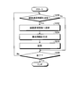
- FIG. 9 is a flowchart of the node management process.
- FIG. 10 is a flowchart of the information processing.
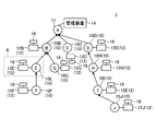
- FIG. 1 is a schematic diagram illustrating an example of the communication control system 1 according to the present embodiment.
- the communication control system 1 includes a plurality of node terminals 10, a root node terminal 11, a node management device 12, a management device 14, and a target device 16.
- the plurality of node terminals 10 and the root node terminals 11 form a tree-structured network with the root node terminals 11 as root nodes.
- the root node is a parent node for all the node terminals 10 in the communication control system 1, and may be referred to as a root node, an aggregation device, or the like.
- a plurality of node terminals 10 are wirelessly connected to the root node terminal 11 in a tree structure.
- the node terminal 10 is a node that configures a multi-hop communication network.
- the node terminal 10 is a communication device that relays information by multi-hop communication and performs wireless communication.
- another node terminal 10 relays communication from the transmission source node terminal 10 to the transmission destination node terminal 10 (or the root node terminal 11). Therefore, the information transmitted by each node terminal 10 is relayed by another node terminal 10 or transmitted directly to the root node terminal 11.
- the root node terminal 11 aggregates information transmitted from each of the node terminals 10.
- a known communication method may be used for the multi-hop communication between the node terminal 10 and the root node terminal 11.
- the node terminal 10 and the root node terminal 11 perform wireless communication by multi-hop communication using a known time-division wireless communication method.
- FIG. 1 shows an example of uplink communication from each of the node terminals 10 to the root node terminal 11.
- the alphabet shown for each of the root node terminal 11 and the plurality of node terminals 10 is an example of the ID (identification information) of each of the root node terminal 11 and the plurality of node terminals 10.
- the arrow in FIG. 1 indicates the direction of information transmission.
- the other node terminal 10 with which the node terminal 10 performs wireless communication and which is closer to the root node terminal 11 than the root node terminal 11 is defined as a parent node. Closer to the root node terminal 11 indicates that the number of hops to the root node terminal 11 is smaller than that of the node terminal 10.
- another node terminal 10 with which the node terminal 10 performs wireless communication that is, another lower node terminal 10 farther from the root node terminal 11 is defined as a child node. Being farther from the root node terminal 11 indicates that the number of hops to the root node terminal 11 is larger than that of the node terminal 10.
- the parent nodes of the node terminal 10E are the node terminal 10B and the root node terminal 11.
- the child node of the node terminal 10E is the node terminal 10F.
- the child nodes of the node terminal 10B are a node terminal 10E, a node terminal 10F, and a node terminal 10G.
- the child nodes of the root node terminal 11 are all the node terminals 10.
- the node management device 12 is an example of the communication control device of the present invention.
- the node management device 12 is a device for controlling multi-hop communication by the node terminal 10.
- one node management device 12 is connected to one node terminal 10. That is, as shown in FIG. 1, in the present embodiment, one node management device 12 (node management device 12B to node terminal 10J) is provided for each of the plurality of node terminals 10 (node terminals 10B to 10J). Management device 12J) is connected.
- a configuration in which a plurality of node terminals 10 are connected to one node management device 12 may be employed.
- one or a plurality of node terminals 10 and the root node terminal 11 may be connected to one node management device 12. In this case, the node management device 12 may individually control the multi-hop communication of the plurality of connected node terminals 10.
- node management device 12 when an unspecified node management device 12 is indicated, it will be simply described as the node management device 12. In addition, when a specific node management device 12 is indicated, an explanation will be given by giving an alphabet. Also, a description will be given on the assumption that the node terminal 10 and the node management device 12 to which the same alphabet is assigned are connected. For example, the node management device 12E is connected to the node terminal 10E.
- the node terminal 10 and the node management device 12 need only be connected so that signals can be transmitted and received, and may be either a wireless connection or a wired connection.
- a case where the node terminal 10 and the node management device 12 are connected by wire will be described as an example.
- the management device 14 is a device for managing the root node terminal 11.
- the management device 14 manages information collected from the node terminal 10 to the root node terminal 11.
- the management device 14 generates and manages configuration information indicating the network configuration of the multi-hop communication network (details will be described later).
- the target device 16 is a device to be monitored by the node management device 12.
- the node management device 12 is, for example, various detection devices. Specifically, the node management device 12 is a photographing device that detects a photographed image by photographing a specific region, a sensor that detects environment information of the specific region, and the like.
- the environmental information includes, for example, atmospheric components, air temperature, water temperature, light amount of ultraviolet rays and the like, sound volume, and the like, but is not limited thereto. In the present embodiment, a case will be described as an example where the target device 16 sequentially outputs detection results of detecting environment information to the connected node management devices 12.
- one target device 16 is connected to one node management device 12 as an example. That is, as shown in FIG. 1, in the present embodiment, one target device 16 (target device 16B to target device 16B) is assigned to each of a plurality of node management devices 12 (node management devices 12B to 12J). 16J) are connected.
- one node management device 12 to which one target device 16 is connected is connected to each of the node terminals 10 configuring the communication control system 1.
- a configuration in which a plurality of target devices 16 are connected to one node management device 12 may be employed.
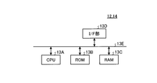
- FIG. 2 is an example of a hardware configuration diagram of the node management device 12 and the management device 14.
- the node management device 12 and the management device 14 include a CPU (Central Processing Unit) 13A, a ROM (Read Only Memory) 13B, a RAM (Random Access Memory) 13C, an I / F unit 13D, and the like, which are mutually connected by a bus 13E. And has a hardware configuration using a normal computer.
- CPU Central Processing Unit
- ROM Read Only Memory
- RAM Random Access Memory
- I / F unit 13D I / F unit
- the CPU 13A is an arithmetic device that controls the node management device 12 and the management device 14 according to the present embodiment.
- the ROM 13B stores a program for implementing various processes by the CPU 13A and the like.
- the RAM 13C stores data necessary for various processes by the CPU 13A.
- the I / F unit 13D is an interface for connecting to an external device or the like.
- the program executed by each of the node management device 12 and the management device 14 according to the present embodiment is provided by being incorporated in the ROM 13B or the like in advance.
- the program executed by each of the node management device 12 and the management device 14 according to the present embodiment is a file in a format that can be installed or executed on each of the node management device 12 and the management device 14, and is a CD-ROM. , A flexible disk (FD), a CD-R, a DVD (Digital @ Versatile @ Disk), or another computer-readable recording medium.
- FIG. 3 is a functional block diagram showing a functional configuration of the node terminal 10, the root node terminal 11, the node management device 12, and the management device 14.
- the node terminal 10E, the node management device 12E, and the node terminal 10E (in the dotted line A in FIG. 1), the root node terminal 11, and the management device 14 in the communication control system 1 shown in FIG. ,
- the functional block diagram of FIG. Note that the other node terminals 10 (node terminals 10B to 10D, node terminals 10F to 10J) and other node management devices 12 (node management devices 12B to 12D, node management devices 12F to 12F)
- the functional configuration of the node terminal 12J) is the same as that of the node terminal 10E and the node management device 12E shown in FIG.
- the node terminal 10E includes a wireless communication unit 20A, a communication unit 20B, and a storage unit 20C.
- the wireless communication unit 20A is a communication function unit that performs multi-hop communication with another node terminal 10.
- the wireless communication unit 20A may be realized by a known wireless function for performing multi-hop communication.
- the communication unit 20B is a communication function unit that performs communication with the node management device 12E.
- the storage unit 20C stores various information.
- the storage unit 20C is, for example, a memory card such as an SD card, a semiconductor memory device such as a flash memory, a USB (Universal Serial Bus) memory, or the like.
- the storage unit 20C stores the ID of the node terminal 10E equipped with the storage unit 20C, the number of hops of the node terminal 10E to the root node terminal 11, and the route information 20D.
- the route information 20D is information indicating a communication route with another node terminal 10 that has already established a wireless connection with the node terminal 10E.
- the wireless communication unit 20A of the node terminal 10E executes a known network topology construction process by multi-hop communication, and establishes a connection with another node terminal 10B (in the example shown in FIG. 3, the node terminal 10B and the node terminal 10F). Then, the wireless communication unit 20A uses the IDs of the other node terminals 10 (node terminals 10B and 10F) that have established the connection and the number of hops of these other nodes to the root node terminal 11 as the route information 20D. Register in storage unit 20C.
- the storage unit 20C stores the ID and the hop count of the other node terminal 10 that has established the connection.
- the information 20D is registered. Note that the wireless communication unit 20A appropriately updates the route information 20D according to the wireless communication status with another node terminal 10.
- FIG. 4 is a schematic diagram showing an example of the data configuration of the route information 20D.
- FIG. 4 illustrates an example of the route information 20D stored in the storage unit 20C of the node terminal 10E.
- the route information 20D associates the ID of another node terminal 10 that has already established a wireless connection with the node terminal 10E, and the number of hops of the node terminal 10 identified by the ID to the root node terminal 11. Information.
- node management device 12 will be described.
- the node management device 12E connected to the node terminal 10E will be described as an example.
- the functional configurations of the other node management devices 12 are the same as those of the node management device 12E.
- the node management device 12E includes a control unit 22A, a storage unit 22B, a first communication unit 22C, and a second communication unit 22D.
- the control unit 22A, the storage unit 22B, the second communication unit 22D, and the first communication unit 22C are connected via a bus.
- the control unit 22A controls the node management device 12E.
- the storage unit 22B stores various information.
- the storage unit 22B is, for example, a semiconductor memory device such as a flash memory, a hard disk, an optical disk, a RAM, or the like. Note that the storage unit 22B may be a storage device provided outside the node management device 12E. Further, the storage unit 22B may be one or a plurality of storage media.
- the first communication unit 22C is a communication function unit that communicates with the target device 16.
- the second communication unit 22D is a communication function unit that communicates with the node terminal 10E.
- the control unit 22A includes a communication control unit 22E.
- the communication control unit 22E is realized by, for example, one or a plurality of processors.
- the communication control unit 22E may be realized by causing a processor such as a CPU to execute a program, that is, by software.
- the communication control unit 22E may be realized by a processor such as a dedicated IC (Integrated Circuit), that is, hardware.
- the communication control unit 22E may be realized by using software and hardware together.
- the wireless communication unit 20A of the node terminal 10E performs the multi-hop communication of the first adjacent communication information with the destination being the root node terminal 11.
- the first adjacent communication information is adjacent communication information transmitted when the node terminal 10E connected to the node management device 12E performs multi-hop communication with the information toward the root node terminal 11 from the own node terminal as a source. is there.
- the adjacent communication information is information including an ID of the own node and an ID of an adjacent parent node that has established a connection to the own node.
- the first adjacent communication information includes the first identification information and the second identification information.
- the first identification information is the ID of the first node terminal.
- the first node terminal indicates a node terminal 10 that is a source of information among the plurality of node terminals 10. That is, the first identification information is the ID of the node terminal 10 that has transmitted the information. In other words, the first identification information is the ID of the own node of the node terminal 10 that has transmitted the information. For example, when the node terminal 10E is the source of the information, the first identification information is the ID “E” of the node terminal 10E.
- the second identification information is the ID of the second node terminal.
- the second node terminal is a parent node adjacent to the information source node terminal 10 on the communication path from the first node terminal, which is the information source node terminal 10, to the root node terminal 11. That is, the second identification information is the ID of the parent node adjacent to the node terminal 10 that has transmitted the information. In other words, the second identification information is the ID of an adjacent parent node that has established a connection to the node terminal 10 that has transmitted the information.
- the second identification information is the ID “B” of the node terminal 10B, which is an adjacent parent node that has established a connection with the node terminal 10E.
- the radio communication unit 20A of the node terminal 10E generates the first adjacent communication information using the route information 20D stored in the node terminal 10E.
- the radio communication unit 20A of the node terminal 10E reads the route information 20D from the storage unit 20C. Also, the wireless communication unit 20A of the node terminal 10E reads the ID of the node terminal 10E and the number of hops to the root node terminal 11 of the node terminal 10E from the storage unit 20C.
- the wireless communication unit 20A of the node terminal 10E generates the first adjacent communication information using the acquired route information 20D and the hop count of the node terminal 10E.
- the wireless communication unit 20A of the node terminal 10E specifies the ID of the node terminal 10E read from the storage unit 20C as the first identification information.
- the radio communication unit 20A of the node terminal 10E specifies the second identification information.
- the path information 20D includes the ID of the other node terminal 10 with which the node terminal 10E having the storage unit 20C storing the path information 20D establishes a wireless connection, and the node terminal identified by the ID. This is information in which 10 hop numbers are associated with each other. For this reason, the radio communication unit 20A of the node terminal 10E specifies, as the second identification information, the ID corresponding to the hop number obtained by subtracting “1” from the hop number of the node terminal 10E in the route information 20D.
- the wireless communication unit 20A of the node terminal 10E reads the route information 20D illustrated in FIG. 4 from the storage unit 20C.
- the wireless communication unit 20A of the node terminal 10E specifies the ID “B” corresponding to the hop number “1” obtained by subtracting “1” from the hop number “2” as the second identification information.
- the wireless communication unit 20A of the node terminal 10E generates the specified first identification information and the specified second identification information as the first adjacent communication information, and outputs the first adjacent communication information to the node management device 12E via the communication unit 20B.
- the communication control unit 22E of the node management device 12E outputs the first adjacent communication information acquired from the node terminal 10E to the node terminal 10E. In other words, the communication control unit 22E controls the node terminal 10E such that multihop communication is performed on the first adjacent communication information with the root node terminal 11 as a destination.
- the communication unit 20B of the node terminal 10E performs multi-hop communication of the first adjacent communication information with the root node terminal 11 as a destination.
- the radio communication unit 20A of the node terminal 10E may perform multi-hop communication of the first adjacent communication information with the root node terminal 11 as a destination when a predetermined condition is satisfied.
- the predetermined condition may be determined in advance. For example, the predetermined condition is every predetermined time or when a new detection result is obtained from the target device 16. Note that the predetermined condition may be appropriately changed by a user's operation instruction or the like.
- the communication control unit 22E of the node management device 12E transmits the communication instruction information including the first adjacent communication information received from the node terminal 10E and the detection result obtained from the target device 16 via the second communication unit 22D. May be output to the node terminal 10E.
- the wireless communication unit 20A of the node terminal 10E that has received the communication instruction information performs multi-hop communication with the first adjacent communication information and the detection result of the target device 16 included in the communication instruction information, with the root node terminal 11 as a destination. Good.
- the identification of the first identification information and the second identification information and the generation of the first adjacent communication information may be performed by the communication control unit 22E of the node management device 12. That is, the communication control unit 22E calculates the first identification information of the node terminal 10E and the second identification information of the node terminal 10B adjacent to the node terminal 10E on the communication path from the node terminal 10E to the root node terminal 11.
- the node terminal 10E may be controlled such that the first adjacent communication information including the multi-hop communication is transmitted to the root node terminal 11 as a destination.
- the communication control unit 22E may control the node terminal 10E such that the first adjacent communication information and the detection result detected by the target device 16 are subjected to multi-hop communication with the root node terminal 11 as a destination. Under the control of these node management devices 12, the node terminal 10 may execute multi-hop communication.
- the node terminal 10E when the node terminal 10E performs multi-hop communication of information toward the root node terminal 11 with the node terminal 10E as a source, the node terminal 10E performs multi-hop communication of the first adjacent communication information with the root node terminal 11 as a destination. .
- node terminals 10 node terminals 10B to 10D, node terminals 10F to 10J
- node management devices 12 node management devices 12B to 12D, node management devices 12F to 12D included in the communication control system 1.
- the node management device 12J also performs the same processing as the node terminal 10E and the node management device 12E.
- the plurality of node terminals 10 constituting the communication control system 1 perform multi-hop communication toward the root node terminal 11 with information originating from each of the nodes, the first identification information being the ID of the node terminal 10.
- the first adjacent communication information including the ID of the adjacent parent node that has established a connection with the node terminal 10 is communicated to the root node terminal 11 by multi-hop communication. Therefore, the first adjacent communication information transmitted from each of the node terminals 10 is relayed by the other node terminals 10 and sequentially transmitted to the root node terminal 11.
- the wireless communication unit 20A of the node terminal 10E may receive the second adjacent communication information from another node terminal 10 (for example, the node terminal 10F) corresponding to the child node.
- another node terminal 10 for example, the node terminal 10F
- the second adjacent communication information is the first adjacent communication information transmitted by multi-hop communication from another node terminal 10 to the node terminal 10E. That is, the second adjacent communication information is adjacent communication information transmitted from a node terminal 10 other than the node terminal 10E connected to the node management device 12E as a source.
- the second adjacent communication information includes the third identification information and the fourth identification information.
- the third identification information is the ID of the third node terminal.
- the third identification information is an ID of the node terminal 10 having a larger number of hops from the root node terminal 11 than the node terminal 10E that has received the second adjacent communication information.
- the third identification information is the ID of the node terminal 10 of the child node that is adjacent or non-adjacent to the node terminal 10E that has received the second adjacent communication information.
- the third identification information is the ID of the node terminal 10 when the node terminal 10 of the child node of the node terminal 10E that has received the second adjacent communication information is the source of the information.
- the third identification information is the ID of the own node of the node terminal 10 that is the source of the information, similarly to the first identification information.
- the third identification information is an ID of the node terminal 10 that is different from the node terminal 10E that has received the second adjacent communication information including the third identification information and has another node terminal 10 as a source of the information. is there.
- the fourth identification information is the ID of the fourth node terminal.
- the fourth node terminal is a parent node adjacent to the information source node terminal 10 on the communication path from the third node terminal, which is the information source node terminal 10, to the root node terminal 11. That is, similarly to the second identification information, the fourth identification information is the ID of the parent node adjacent to the node terminal 10 that has transmitted the information. However, the fourth identification information is different from the node terminal 10E that has received the second adjacent communication information including the fourth identification information, and is different from the node terminal 10 when another node terminal 10 is the source of the information. This is the ID of the adjacent parent node.
- both the first identification information and the third identification information are the IDs of the node terminals 10 that transmitted the information. Therefore, when the first identification information and the third identification information are collectively described, they may be described as their own node IDs.
- both the second identification information and the fourth identification information are the IDs of adjacent parent nodes that have established a connection with the node terminal 10 that has transmitted the information. Therefore, when the second identification information and the fourth identification information are collectively described, they may be described as adjacent parent node IDs.
- the wireless communication unit 20A of the node terminal 10E receives the second adjacent communication information from another node terminal 10 (for example, the node terminal 10F) corresponding to the child node, the wireless communication unit 20A of the node terminal 10E
- the node terminal 10E is controlled such that multi-hop communication is performed on the two adjacent communication information with the root node terminal 11 as a destination.
- the wireless communication unit 20A of the node terminal 10E relays the second adjacent communication information without adding new information, and performs multi-hop communication toward the root node terminal 11 as it is.
- the communication control unit 22E of the node management device 12E controls the node terminal 10E such that the second adjacent communication information is subjected to multi-hop communication as it is with the root node terminal 11 as a destination, thereby realizing the above processing. You may.
- the wireless communication unit 20A of the node terminal 10E performs multi-hop communication with the root node terminal 11 as a destination without adding any information to the second adjacent communication information received from the node terminal 10F.
- the node terminal 10E when the node terminal 10E receives the second neighboring communication information from the other node terminal 10F which is a child node of the node terminal 10E, the node terminal 10E receives some information from the received second neighboring communication information.
- the multi-hop communication is performed with the root node terminal 11 as a destination without adding the.
- node terminals 10 node terminals 10B to 10D, node terminals 10F to 10J
- node management devices 12 node management devices 12B to 12D, node management devices 12F to 12D included in the communication control system 1.
- the node management device 12J also performs the same processing as the node terminal 10E and the node management device 12E.
- each of the plurality of node terminals 10 configuring the communication control system 1 receives the second adjacent communication information from another node terminal 10 corresponding to each child node, the second adjacent communication information To the root node terminal 11 as it is.
- the first neighboring communication information transmitted from each of the node terminals 10 is received as the second neighboring communication information by the other node terminals 10, and is relayed by the other node terminals 10 without adding new information. , To the root node terminal 11.
- FIGS. 5 and 6 are explanatory diagrams showing an example of communication of the adjacent communication information 30 relayed by multi-hop communication.
- the first adjacent communication information and the second adjacent communication information are collectively referred to as adjacent communication information 30 and described.
- the illustration of the node management device 12, the management device 14, and the target device 16 is partially omitted.
- FIG. 5 is an explanatory diagram assuming that the node terminal 10F in the communication control system 1 is a source of information.
- the node terminal 10F under the control of the node management device 12F connected to the node terminal 10F, the node terminal 10F receives the own node ID (first identification information) “F” and the adjacent parent node ID (second identification information) “E”. And multi-hop communication is performed toward the root node terminal 11 with the adjacent communication information 30 ⁇ / b> F as the first adjacent communication information including the following (step S ⁇ b> 1).
- each node terminal 10 (node terminal 10F, node terminal 10B) existing on the communication path from the node terminal 10F to the root node terminal 11 receives the adjacent communication information 30F as the second adjacent communication information. Then, these node terminals 10 (node terminal 10F, node terminal 10B) sequentially pass the received adjacent communication information 30F to another node terminal 10 (node terminal 10B) and the root node terminal 11 that are adjacent on the upper side as they are. (Step S2, Step S3). Therefore, the adjacent communication information 30F transmitted from the node terminal 10F is notified to the root node terminal 11 through a plurality of node terminals 10 (node terminals 10E and 10B) in a multi-hop manner.
- FIG. 6 is an explanatory diagram assuming that the node terminal 10H in the communication control system 1 is a source of information.
- the node terminal 10H under the control of the node management device 12H connected to the node terminal 10H, the node terminal 10H sets its own node ID (first identification information) “H” and the adjacent parent node ID (second identification information) “D”. Is transmitted to the root node terminal 11 in a multi-hop manner (step S10).
- each node terminal 10D existing on the communication path from the node terminal 10H to the root node terminal 11 receives the adjacent communication information 30H as the second adjacent communication information. Then, the node terminal 10D transfers the received adjacent communication information 30H to the root node terminal 11 as it is (Step S11). Therefore, the adjacent communication information 30H transmitted from the node terminal 10H is notified to the root node terminal 11 via the node terminal 10D in a multi-hop manner.
- the root node terminal 11 does not The adjacent communication information 30 having the same data amount arrives. That is, in the case where the node terminal 10 having a larger number of hops is the source of information and the case where the node terminal 10 having the smaller number of hops is the source of information, the adjacent communication information 30 having substantially the same data amount is the root. It will reach the node terminal 11. For this reason, in the communication control system 1 of the present embodiment, an increase in the data amount of the adjacent communication information 30 to be multihop-communicated is suppressed by the number of hops of the source node terminal 10.
- the root node terminal 11 includes a wireless communication unit 24A, a communication unit 24B, and a storage unit 24C.
- the wireless communication unit 24A is a communication function unit that performs multi-hop communication with the node terminal 10.
- the wireless communication unit 24A may be realized by a known wireless function for performing multi-hop communication.
- the communication unit 24B is a communication function unit that performs communication with the management device 14.
- the storage unit 24C stores various information.
- the storage unit 24C is, for example, a memory card such as an SD card, a semiconductor memory device such as a flash memory, or a USB (Universal Serial Bus) memory.
- a memory card such as an SD card
- a semiconductor memory device such as a flash memory
- USB Universal Serial Bus
- adjacent communication information 30 received from each of the plurality of node terminals 10 by multi-hop communication is stored.
- the wireless communication unit 24A Upon receiving the adjacent communication information 30 from the node terminal 10, the wireless communication unit 24A stores the received adjacent communication information 30 in the storage unit 24C.
- the communication unit 24B outputs the newly stored adjacent communication information 30 to the management device 14 each time the new adjacent communication information 30 is stored in the storage unit 24C.
- the management device 14 includes a control unit 26A, a communication unit 26B, and a storage unit 26C.
- the control unit 26A, the communication unit 26B, and the storage unit 26C are connected via a bus.
- the control unit 26A controls the management device 14.
- the communication unit 26B is a communication function unit that communicates with the communication unit 24B of the root node terminal 11.
- the storage unit 26C stores various information.
- the storage unit 26C stores the connection management information 26D and the configuration information 26E.
- connection management information 26D is a database for managing the adjacent communication information 30 received by the root node terminal 11.
- the data format of the connection management information 26D is not limited to a database.
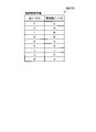
- FIG. 7 is a schematic diagram showing an example of the data configuration of the connection management information 26D.
- the connection management information 26 ⁇ / b> D registers the adjacent communication information 30 that is multi-hop-communicated to the root node terminal 11 from each of the node terminals 10 as a transmission source.
- the connection management information 26 ⁇ / b> D registers a plurality of pieces of adjacent communication information 30 in which the own node ID and the adjacent parent node ID of each of the node terminals 10 are associated.
- the adjacent communication information 30 is a general term for the first adjacent communication information and the second adjacent communication information.
- the own node ID is a general term for the first identification information and the third identification information.
- the adjacent parent node ID is a general term for the second identification information and the fourth identification information.
- the configuration information 26E is information indicating the network configuration of the multi-hop communication network configured by the root node terminal 11 and the plurality of node terminals 10 in the communication control system 1.
- the configuration information 26E is information indicating the established connection relationship between each of the plurality of node terminals 10 included in the communication control system 1 and another node terminal 10 or the root node terminal 11. That is, the configuration information 26E is information indicating a tree configuration configured by a wireless communication network including the root node terminal 11 and the plurality of node terminals 10.
- the configuration information 26E is generated and updated by the control unit 26A.
- the control unit 26A controls the management device 14.
- the control unit 26A includes an acquisition unit 26F and a generation unit 26G.
- the acquisition unit 26F and the generation unit 26G are realized by, for example, one or a plurality of processors.
- these units may be realized by causing a processor such as a CPU to execute a program, that is, by software.
- a processor such as a CPU
- Each of the above units may be realized by a processor such as a dedicated IC, that is, hardware.
- Each of the above units may be realized by using software and hardware together. When a plurality of processors are used, each processor may realize one of the units, or may realize two or more of the units.
- the acquisition unit 26F acquires the adjacent communication information 30 from the root node terminal 11. Each time the wireless communication unit 24A of the root node terminal 11 receives the new adjacent communication information 30, the acquisition unit 26F receives the new adjacent communication information 30 from the root node terminal 11 via the communication unit 26B, and performs connection management. Register in information 26D.
- the generation unit 26G generates configuration information 26E indicating the network configuration of the multi-hop communication network based on the plurality of adjacent communication information 30.
- the generation unit 26G generates configuration information using the connection management information 26D (see FIG. 7).
- the generation unit 26G communicates with the node terminal 10 identified by the adjacent parent node ID included in the adjacent communication information 30 and another adjacent communication
- the connection relationship is sequentially specified so that the node terminal 10 identified by the own node ID included in the information 30 is connected.
- FIG. 8 is an explanatory diagram of one example of specifying the connection relationship between the node terminals 10.
- the generation unit 26G transmits a plurality of adjacent communication information 30 (adjacent communication information 30B to adjacent communication information 30) that are multi-hop-communicated toward the root node terminal 11 with each of the node terminals 10 (node terminals 10B to 10J) as a source of information.
- adjacent communication information 30B adjacent communication information 30
- the node terminal 10 identified by the adjacent parent node ID included in the adjacent communication information 30 and the node terminal 10 identified by the own node ID included in the other adjacent communication information 30 include:
- the connection relation 28 is specified so as to be connected.
- the generation unit 26G By specifying the connection relationship 28, the generation unit 26G generates, for example, configuration information 26E represented by a tree configuration illustrated in FIG. 5 or FIG.
- the generation unit 26G updates the configuration information 26E stored in the storage unit 26C by storing the generated configuration information 26E in the storage unit 26C.
- FIG. 9 is a flowchart illustrating an example of a procedure of a node management procedure executed by the node management apparatus 12.
- the communication control unit 22E determines whether a predetermined condition is satisfied (step S100).
- the communication control unit 22E performs the determination in step S100, for example, by determining whether a predetermined time has elapsed. Note that the communication control unit 22E may determine the step S100 by determining whether a new detection result has been obtained from the target device 16.
- Step S100 If it is determined that the predetermined condition is satisfied (step S100: Yes), the process proceeds to step S102.
- Step S102 the communication control unit 22E acquires the first adjacent communication information from the connected node terminal 10 (Step S102).
- the communication control unit 22E outputs the first adjacent communication information acquired in step S102 and the detection result of the target device 16 to the connected node terminal 10 (step S104).
- the node terminal 10 performs multi-hop communication of the first adjacent communication information and the detection result received from the node management device 12 with the root node terminal 11 as a destination.
- Step S106 determines whether to end the node management process. If an affirmative determination is made in step S106 (step S106: Yes), this routine ends. If a negative determination is made in step S106 (step S106: No), the process returns to step S100. On the other hand, if a negative determination is made in step S100 (step S100: No), the process proceeds to step S106.
- FIG. 10 is a flowchart illustrating an example of a procedure of information processing executed by the management device 14.
- the acquisition unit 26F of the management device 14 determines whether the root node terminal 11 has received the adjacent communication information 30 from the node terminal 10 (Step S200). If an affirmative determination is made in step S200 (step S200: Yes), the process proceeds to step S202. If a negative determination is made in step S200, the process proceeds to step S208 described below.
- step S202 the acquiring unit 26F registers the adjacent communication information 30 newly received by the root node terminal 11 in the connection management information 26D (step S202).
- the generation unit 26G generates the configuration information 26E using the plurality of adjacent communication information 30 indicated in the connection management information 26D (Step S204).
- the generation unit 26G updates the configuration information 26E by storing the configuration information 26E generated in step S204 in the storage unit 26C (step S206).
- Step S208 determines whether to terminate the information processing. If a negative determination is made in step S208 (step S208: No), the process returns to step S200. On the other hand, if an affirmative determination is made in step S208 (step S208: Yes), this routine ends.
- the communication control unit 22 ⁇ / b> E includes the first identification information (ID) of the first node terminal and the first node on the communication path from the first node terminal to the root node terminal 11.
- the first adjacent communication information including the second identification information (ID) of the second node terminal (node terminal 10) adjacent to the terminal is transmitted to the first node terminal ( It controls the node terminal 10).
- the node terminal 10 transmits the first adjacent communication information including the first identification information of the node terminal 10 and the second identification information of the adjacent parent node that has established communication with the node terminal 10 to the root node. Multi-hop communication can be performed with the terminal 11 as a destination.
- each of the plurality of node terminals 10 constituting the multi-hop communication network is represented by a simple configuration such as the first identification information and the second identification information.
- the network configuration of the multi-hop communication network can be easily managed.
- the node management device 12 of the present embodiment can easily manage the network configuration of the multi-hop communication network.
- each of the node terminals 10 performs multi-hop communication with the identification information of all the child nodes connected to the own node and the number of hops of each of the child nodes to the root node terminal 11 as communication information. For this reason, the amount of information transmitted to the root node terminal 11 increases as the number of hops in the multi-hop communication network including the node terminal 10 increases.
- the node terminal 10 has the first identification information of the node terminal 10 and the second identification information of the parent node adjacent to the node terminal 10. And multi-hop communication with the first adjacent communication information including the destination as the destination of the root node terminal 11.
- the generation unit 26G of the management device 14 connected to the root node terminal 11 indicates a network configuration of the multi-hop communication network based on the plurality of first neighboring communication information transmitted from each of the plurality of node terminals 10.
- the configuration information 26E is generated.
- the first adjacent communication information indicates the communication status of the node terminal 10 with a simple configuration such as the first identification information and the second identification information.
- the generation unit 26G can easily generate the configuration information 26E of the multi-hop communication network. Therefore, the communication control system 1 of the present embodiment can easily manage the configuration information 26E in addition to the above effects.
- the case where the node terminal 10 and the node management device 12 are configured separately is shown as an example.
- the node terminal 10 and the node management device 12 may be integrally configured.
- the configuration may be such that the node terminal 10 includes at least the communication control unit 22E.
- the case where the root node terminal 11 and the management device 14 are configured separately is described as an example.
- the root node terminal 11 and the management device 14 may be integrally configured.
- the root node terminal 11 may be configured to include at least the generation unit 26G.
- the program for executing the above processing is a file in an installable format or an executable format in the form of a CD-ROM, a flexible disk (FD), a CD-R, or a DVD (Digital Versatile Disk). ), A USB (Universal Serial Bus) memory or other computer-readable recording medium, or may be provided, or may be provided or distributed via a network such as the Internet.
- various programs may be configured to be provided by being incorporated in a ROM or the like in advance.
- the program for executing the above-described processing in the above-described embodiment has a module configuration including the above-described respective functional units.
- a CPU processor circuit
- ROM read-only memory
- HDD high-density dynamic memory
- the above-described functional units are loaded on the RAM (main memory), and the above-described functional units are generated on the RAM (main memory).
- ASIC Application Specific Integrated Circuit
- FPGA Field-Programmable Gate Array
Landscapes
- Engineering & Computer Science (AREA)
- Computer Networks & Wireless Communication (AREA)
- Signal Processing (AREA)
- Mobile Radio Communication Systems (AREA)
Abstract
通信制御部(22E)は、第1ノード端末の第1識別情報と、第1ノード端末から根ノード端末(11)に向かう通信経路上で該第1ノード端末に隣接する第2ノード端末の第2識別情報と、を含む第1隣接通信情報を、根ノード端末(11)を宛先としてマルチホップ通信するように第1ノード端末を制御する。
Description
本発明の実施の形態は、通信制御装置、通信制御システム、通信制御方法、および通信制御プログラムに関する。
送信元のノード端末から送信先のノード端末への通信を、他のノード端末が中継して通信する、マルチホップ通信が知られている。また、メッシュ型のマルチホップ通信網では、ある通信経路におけるノード端末が通信不能となった場合、他のノード端末により他の通信経路が新たに構成される。また、新たなノード端末が追加された場合、該新たなノード端末によって他のノード端末との新たな通信経路が追加構成される。このように、マルチホップ通信を用いたマルチホップ通信網では、通信状況に合わせてネットワークのツリー構成が最適化されるように設計されている。このため、マルチホップ通信網では、接続状況の変化などに応じて、ネットワーク構成が変化する。
ここで、マルチホップ通信網を構成する各ノード端末は、接続を確立している他のノード端末との接続関係を示す接続関係情報を、根ノードを宛先として送信する。従来では、この接続関係情報として、自端末に対して根ノード端末から離れる方向に向かう下り方向の通信経路上に直接または他のノード端末を介して接続されている全ての子ノード端末の識別情報と、これらの子ノード端末の各々のホップ数と、自端末の識別情報およびホップ数と、を含む情報を、根ノード端末に向かってマルチホップ通信していた。このため、従来技術では、ホップ数が増えるほど、マルチホップ通信される経路情報のデータ量が増大し、根ノード端末側でマルチホップ通信網のネットワーク構成を容易に管理することは困難であった。
本発明が解決しようとする課題は、マルチホップ通信網のネットワーク構成を容易に管理可能とすることができる、通信制御装置、通信制御システム、通信制御方法、および通信制御プログラムを提供することである。
実施の形態の通信制御装置は、マルチホップ通信網を構成する第1ノード端末の第1識別情報と、前記第1ノード端末から根ノード端末に向かう通信経路上で該第1ノード端末に隣接する第2ノード端末の第2識別情報と、を含む第1隣接通信情報を、前記根ノード端末を宛先としてマルチホップ通信するように前記第1ノード端末を制御する通信制御部、を備える。
以下に添付図面を参照して、通信制御装置、通信制御システム、通信制御方法、および通信制御プログラムを詳細に説明する。
図1は、本実施の形態の通信制御システム1の一例を示す模式図である。
通信制御システム1は、複数のノード端末10と、根ノード端末11と、ノード管理装置12と、管理装置14と、対象装置16と、を備える。
複数のノード端末10と根ノード端末11は、根ノード端末11を根ノードとしたツリー構成のネットワークを構成する。根ノードは、通信制御システム1における全てのノード端末10に対する親ノードであり、ルートノード、集約装置、などと称される場合もある。本実施の形態の通信制御システム1では、根ノード端末11に対して、複数のノード端末10がツリー構造で無線接続されている。
ノード端末10は、マルチホップ通信網を構成するノードである。言い換えると、ノード端末10は、マルチホップ通信により情報を中継して無線通信する、通信装置である。マルチホップ通信では、送信元のノード端末10から送信先のノード端末10(または根ノード端末11)への通信を、他のノード端末10が中継して通信する。このため、各ノード端末10が送信した情報は、他のノード端末10により中継され、または直接、根ノード端末11へ送信される。根ノード端末11は、ノード端末10の各々から送信された情報を集約する。
なお、ノード端末10および根ノード端末11によるマルチホップ通信には、公知の通信方法を用いればよい。例えば、ノード端末10および根ノード端末11は、公知の時分割無線通信方式を用いたマルチホップ通信により、無線通信を行う。
図1には、ノード端末10の各々から根ノード端末11への上り方向の通信の一例を示した。なお、図1において、根ノード端末11および複数のノード端末10の各々に示したアルファベットは、根ノード端末11および複数のノード端末10の各々のID(識別情報)の一例である。また、図1中の矢印は、情報の伝達方向を示す。
なお、以下の説明において、不特定なノード端末10を示す場合には、単にノード端末10として説明する。また、特定のノード端末10を示す場合には、アルファベットを付与して説明する。
本実施の形態では、ノード端末10が無線通信する他のノード端末10であって、根ノード端末11により近い上位側の他のノード端末10を、親ノードと定義する。根ノード端末11により近い、とは、根ノード端末11までのホップ数が、当該ノード端末10より少ない事を示す。同様に、ノード端末10が無線通信する他のノード端末10であって、根ノード端末11からより遠い下位側の他のノード端末10を、子ノードと定義する。根ノード端末11からより遠い、とは、根ノード端末11までのホップ数が、当該ノード端末10より多い事を示す。
例えば、ノード端末10Eの親ノードは、ノード端末10Bおよび根ノード端末11である。また、ノード端末10Eの子ノードは、ノード端末10Fである。また、ノード端末10Bの子ノードは、ノード端末10E、ノード端末10F、およびノード端末10Gである。また、根ノード端末11の子ノードは、全てのノード端末10である。
次に、ノード管理装置12について説明する。ノード管理装置12は、本発明の通信制御装置の一例である。ノード管理装置12は、ノード端末10によるマルチホップ通信を制御するための装置である。本実施の形態では、1つのノード端末10に対して、1つのノード管理装置12が接続されている。すなわち、図1に示すように、本実施の形態では、複数のノード端末10(ノード端末10B~ノード端末10J)の各々に対して、それぞれ、1つのノード管理装置12(ノード管理装置12B~ノード管理装置12J)が接続されている。なお、1つのノード管理装置12に対して、複数のノード端末10が接続された形態であってもよい。なお、1つのノード管理装置12に対して、1または複数のノード端末10と、根ノード端末11と、が接続された形態であってもよい。この場合、ノード管理装置12は、接続された複数のノード端末10のマルチホップ通信を個別に制御すればよい。
なお、以下の説明において、不特定なノード管理装置12を示す場合には、単にノード管理装置12として説明する。また、特定のノード管理装置12を示す場合には、アルファベットを付与して説明する。また、同じアルファベットを付与されたノード端末10とノード管理装置12が、接続されているものとして説明する。例えば、ノード管理装置12Eは、ノード端末10Eに接続されている。
なお、ノード端末10とノード管理装置12は、信号を授受可能に接続されていればよく、無線接続および有線接続の何れであってもよい。本実施の形態では、ノード端末10とノード管理装置12とが有線接続されている場合を、一例として説明する。
管理装置14は、根ノード端末11を管理するための装置である。管理装置14は、ノード端末10から根ノード端末11に集約された情報を管理する。本実施の形態では、管理装置14は、マルチホップ通信網のネットワーク構成を示す構成情報を生成し管理する(詳細後述)。
対象装置16は、ノード管理装置12による監視対象の機器である。ノード管理装置12は、例えば、各種の検出装置である。具体的には、ノード管理装置12は、特定領域を撮影することで撮影画像を検出する撮影装置や、特定領域の環境情報を検出するセンサなどである。環境情報は、例えば、大気の成分、気温、水温、紫外線などの光量、音量、などであるが、これらに限定されない。本実施の形態では、対象装置16は、環境情報を検出した検出結果を、順次、接続されたノード管理装置12へ出力する場合を一例として説明する。
本実施の形態では、1つのノード管理装置12に対して1つの対象装置16が接続されている場合を一例として説明する。すなわち、図1に示すように、本実施の形態では、複数のノード管理装置12(ノード管理装置12B~ノード管理装置12J)の各々に対して、1つの対象装置16(対象装置16B~対象装置16J)が接続されている。
このため、本実施の形態では、通信制御システム1を構成するノード端末10の各々には、1つの対象装置16が接続された1つのノード管理装置12が、接続されている。
なお、1つのノード管理装置12に対して、複数の対象装置16が接続された形態であってもよい。
次に、ノード管理装置12および管理装置14のハードウェア構成を説明する。
図2は、ノード管理装置12および管理装置14のハードウェア構成図の一例である。
ノード管理装置12および管理装置14は、CPU(Central Processing Unit)13A、ROM(Read Only Memory)13B、RAM(Random Access Memory)13C、およびI/F部13D等がバス13Eにより相互に接続されており、通常のコンピュータを利用したハードウェア構成となっている。
CPU13Aは、本実施の形態のノード管理装置12および管理装置14を制御する演算装置である。ROM13Bは、CPU13Aによる各種処理を実現するプログラム等を記憶する。RAM13Cは、CPU13Aによる各種処理に必要なデータを記憶する。I/F部13Dは、外部装置などに接続するためのインターフェースである。
本実施の形態のノード管理装置12および管理装置14の各々で実行されるプログラムは、ROM13B等に予め組み込んで提供される。なお、本実施の形態のノード管理装置12および管理装置14の各々で実行されるプログラムは、ノード管理装置12および管理装置14の各々にインストール可能な形式又は実行可能な形式のファイルでCD-ROM、フレキシブルディスク(FD)、CD-R、DVD(Digital Versatile Disk)等のコンピュータで読み取り可能な記録媒体に記録されて提供するように構成してもよい。
次に、ノード端末10、根ノード端末11、ノード管理装置12、および管理装置14の機能的構成を説明する。
図3は、ノード端末10、根ノード端末11、ノード管理装置12、および管理装置14の機能的構成を示す機能ブロック図である。
なお、図3には、図1に示す通信制御システム1におけるノード端末10E、ノード管理装置12E、およびノード端末10E(図1中、点線A内)と、根ノード端末11と、管理装置14と、の機能ブロック図を示した。なお、他のノード端末10(ノード端末10B~ノード端末10D、ノード端末10F~ノード端末10J)および他のノード管理装置12(ノード管理装置12B~ノード管理装置12D、ノード管理装置12F~ノード管理装置12J)の機能的構成も、図3に示すノード端末10Eおよびノード管理装置12Eと同様である。
ノード端末10Eは、無線通信部20Aと、通信部20Bと、記憶部20Cと、を備える。無線通信部20Aは、他のノード端末10とマルチホップ通信を行う通信機能部である。無線通信部20Aは、マルチホップ通信を行う公知の無線機能で実現すればよい。通信部20Bは、ノード管理装置12Eとの間で通信を行う通信機能部である。
記憶部20Cは、各種情報を記憶する。記憶部20Cは、例えば、SDカードなどのメモリカード、フラッシュメモリ等の半導体メモリ素子、USB(Universal Serial Bus)メモリなどである。
本実施の形態では、記憶部20Cは、当該記憶部20Cを搭載したノード端末10EのIDと、該ノード端末10Eの根ノード端末11までのホップ数と、経路情報20Dを記憶する。
経路情報20Dは、ノード端末10Eと無線接続を確立済の他のノード端末10との通信経路を示す情報である。
ノード端末10Eの無線通信部20Aは、マルチホップ通信による公知のネットワークトポロジ構築処理を実行し、他のノード端末10B(図3に示す例ではノード端末10Bおよびノード端末10F)と接続を確立する。そして、無線通信部20Aは、接続を確立した他のノード端末10(ノード端末10B、ノード端末10F)のIDと、これらの他のノードの根ノード端末11までのホップ数を、経路情報20Dとして記憶部20Cへ登録する。
このため、ノード端末10Eと他のノード端末10との間で無線通信の接続が確立された状態では、記憶部20Cには、接続を確立した他のノード端末10のIDとホップ数を示す経路情報20Dが登録された状態となる。なお、無線通信部20Aは、他のノード端末10との無線通信状況に応じて、経路情報20Dを適宜更新する。
図4は、経路情報20Dのデータ構成の一例を示す模式図である。図4には、ノード端末10Eの記憶部20Cに記憶された経路情報20Dの一例を示した。経路情報20Dは、ノード端末10Eとの間で無線接続を確立済の他のノード端末10のIDと、該IDによって識別されるノード端末10の根ノード端末11までのホップ数と、を対応付けた情報である。
図3に戻り説明を続ける。次に、ノード管理装置12について説明する。ここでは、ノード端末10Eに接続されたノード管理装置12Eを一例として説明する。なお、上述したように、他のノード管理装置12(ノード管理装置12B~ノード管理装置12D、ノード管理装置12F~ノード管理装置12J)の機能的構成も、ノード管理装置12Eと同様である。
ノード管理装置12Eは、制御部22Aと、記憶部22Bと、第1通信部22Cと、第2通信部22Dと、を備える。制御部22Aと、記憶部22Bと、第2通信部22Dと、第1通信部22Cとは、バスを介して接続されている。
制御部22Aは、ノード管理装置12Eを制御する。記憶部22Bは、各種情報を記憶する。記憶部22Bは、例えば、フラッシュメモリ等の半導体メモリ素子、ハードディスク、光ディスク、RAM等である。なお、記憶部22Bは、ノード管理装置12Eの外部に設けられた記憶装置であってもよい。また、記憶部22Bは、1または複数の記憶媒体であってもよい。
第1通信部22Cは、対象装置16と通信する通信機能部である。第2通信部22Dは、ノード端末10Eと通信する通信機能部である。
制御部22Aは、通信制御部22Eを備える。通信制御部22Eは、例えば、1または複数のプロセッサにより実現される。例えば、通信制御部22Eは、CPUなどのプロセッサにプログラムを実行させること、すなわちソフトウェアにより実現してもよい。また、通信制御部22Eは、専用のIC(Integrated Circuit)などのプロセッサ、すなわちハードウェアにより実現してもよい。通信制御部22Eは、ソフトウェアおよびハードウェアを併用して実現してもよい。
ノード端末10Eの無線通信部20Aは、根ノード端末11を宛先として第1隣接通信情報をマルチホップ通信する。
第1隣接通信情報とは、ノード管理装置12Eに接続されたノード端末10Eが自ノード端末を発信元として情報を根ノード端末11へ向かってマルチホップ通信するときに送信される、隣接通信情報である。隣接通信情報とは、自ノードのIDと、該自ノードに対して接続を確立した隣接する親ノードのIDと、を含む情報である。
第1隣接通信情報は、第1識別情報と、第2識別情報と、を含む。
第1識別情報は、第1ノード端末のIDである。第1ノード端末は、複数のノード端末10の内、情報の発信元のノード端末10を示す。すなわち、第1識別情報は、情報の発信元のノード端末10のIDである。言い換えると、第1識別情報は、情報の発信元のノード端末10の、自ノードのIDである。例えば、ノード端末10Eが情報の発信元である場合、第1識別情報は、ノード端末10EのID“E”である。
第2識別情報は、第2ノード端末のIDである。第2ノード端末は、情報の発信元のノード端末10である第1ノード端末から根ノード端末11に向かう通信経路上で、該情報の発信元のノード端末10に隣接する親ノードである。すなわち、第2識別情報は、情報の発信元のノード端末10に隣接する親ノードのIDである。言い換えると、第2識別情報は、情報の発信元のノード端末10に対して接続を確立した隣接する親ノードのIDである。例えば、ノード端末10Eが情報の発信元である場合、第2識別情報は、ノード端末10Eと接続を確立した隣接する親ノードである、ノード端末10BのID“B”である。
ノード端末10Eの無線通信部20Aは、ノード端末10Eに記憶されている経路情報20Dを用いて、第1隣接通信情報を生成する。
詳細には、ノード端末10Eの無線通信部20Aは、記憶部20Cから経路情報20Dを読取る。また、ノード端末10Eの無線通信部20Aは、記憶部20Cから、ノード端末10EのIDおよびノード端末10Eの根ノード端末11までのホップ数を読取る。
そして、ノード端末10Eの無線通信部20Aは、取得した経路情報20Dおよびノード端末10Eのホップ数を用いて、第1隣接通信情報を生成する。
まず、ノード端末10Eの無線通信部20Aは、記憶部20Cから読取ったノード端末10EのIDを、第1識別情報として特定する。
次に、ノード端末10Eの無線通信部20Aは、第2識別情報を特定する。上述したように、経路情報20Dは、当該経路情報20Dを記憶した記憶部20Cを搭載したノード端末10Eが無線接続を確立した、他のノード端末10のIDと、該IDによって識別されるノード端末10のホップ数と、を対応付けた情報である。このため、ノード端末10Eの無線通信部20Aは、経路情報20Dにおける、ノード端末10Eのホップ数から“1”を減算したホップ数に対応するIDを、第2識別情報として特定する。
例えば、ノード端末10Eの根ノード端末11までのホップ数が“2”であると想定する。そして、ノード端末10Eの無線通信部20Aが、図4に示す経路情報20Dを記憶部20Cから読取った場合を想定する。この場合、ノード端末10Eの無線通信部20Aは、該ホップ数“2”から“1”を減算したホップ数“1”に対応するID“B”を、第2識別情報として特定する。
そして、ノード端末10Eの無線通信部20Aは、特定した第1識別情報および第2識別情報を、第1隣接通信情報として生成し、通信部20Bを介してノード管理装置12Eへ出力する。
ノード管理装置12Eの通信制御部22Eは、ノード端末10Eから取得した第1隣接通信情報を、ノード端末10Eへ出力する。言い換えると、通信制御部22Eは、第1隣接通信情報を、根ノード端末11を宛先としてマルチホップ通信するように、ノード端末10Eを制御する。
すると、ノード端末10Eの通信部20Bは、第1隣接通信情報を、根ノード端末11を宛先としてマルチホップ通信する。
なお、ノード端末10Eの無線通信部20Aは、所定条件を満たした時に、根ノード端末11を宛先として第1隣接通信情報をマルチホップ通信すればよい。
所定条件は、予め定めればよい。例えば、所定条件は、予め定めた時間ごとや、対象装置16から新たな検出結果を取得したとき、などである。なお、所定条件は、ユーザの操作指示などによって適宜変更可能としてもよい。
なお、ノード管理装置12Eの通信制御部22Eは、ノード端末10Eから受付けた第1隣接通信情報と、対象装置16から取得した検出結果と、を含む通信指示情報を、第2通信部22Dを介してノード端末10Eへ出力してもよい。
該通信指示情報を受付けたノード端末10Eの無線通信部20Aは、該通信指示情報に含まれる第1隣接通信情報および対象装置16の検出結果を、根ノード端末11を宛先としてマルチホップ通信すればよい。
なお、第1識別情報および第2識別情報の特定や、第1隣接通信情報の生成は、ノード管理装置12の通信制御部22E側で行ってもよい。すなわち、通信制御部22Eが、ノード端末10Eの第1識別情報と、ノード端末10Eから根ノード端末11に向かう通信経路上で該ノード端末10Eに隣接するノード端末10Bの第2識別情報と、を含む第1隣接通信情報を、根ノード端末11を宛先としてマルチホップ通信するように、ノード端末10Eを制御してもよい。また、通信制御部22Eが、第1隣接通信情報および対象装置16で検出された検出結果を、根ノード端末11を宛先としてマルチホップ通信するように、ノード端末10Eを制御してもよい。これらのノード管理装置12の制御により、ノード端末10がマルチホップ通信を実行してもよい。
このように、ノード端末10Eは、ノード端末10Eを発信元として情報を根ノード端末11へ向かってマルチホップ通信するときに、第1隣接通信情報を、根ノード端末11を宛先としてマルチホップ通信する。
通信制御システム1に含まれる他のノード端末10(ノード端末10B~ノード端末10D、ノード端末10F~ノード端末10J)およびノード管理装置12(ノード管理装置12B~ノード管理装置12D、ノード管理装置12F~ノード管理装置12J)もまた、ノード端末10Eおよびノード管理装置12Eと同様の処理を実行する。
このため、通信制御システム1を構成する複数のノード端末10は、それぞれを発信元とした情報を根ノード端末11へ向かってマルチホップ通信するときに、ノード端末10のIDである第1識別情報と、ノード端末10と接続を確立した隣接する親ノードのIDである第2識別情報と、を含む第1隣接通信情報を、根ノード端末11へ向かってマルチホップ通信する。このため、ノード端末10の各々から送信された第1隣接通信情報は、他のノード端末10によって中継されて、根ノード端末11へ順次送信される。
ここで、ノード端末10Eの無線通信部20Aは、子ノードに相当する他のノード端末10(例えば、ノード端末10F)から、第2隣接通信情報を受信する場合がある。
第2隣接通信情報は、他のノード端末10からノード端末10Eへマルチホップ通信により送信されてきた第1隣接通信情報である。すなわち、第2隣接通信情報とは、ノード管理装置12Eに接続されたノード端末10E以外の他のノード端末10を発信元として送信された、隣接通信情報である。
第2隣接通信情報は、第3識別情報と、第4識別情報と、を含む。
第3識別情報は、第3ノード端末のIDである。詳細には、第3識別情報は、第2隣接通信情報を受信したノード端末10Eより、根ノード端末11からのホップ数の大きいノード端末10のIDである。言い換えると、第3識別情報は、第2隣接通信情報を受信したノード端末10Eに対して、隣接または非隣接の子ノードのノード端末10のIDである。そして、第3識別情報は、第2隣接通信情報を受信したノード端末10Eの子ノードのノード端末10が情報の発信元であるときの、該ノード端末10のIDである。
すなわち、第3識別情報は、第1識別情報と同様に、情報の発信元のノード端末10の、自ノードのIDである。但し、第3識別情報は、該第3識別情報を含む第2隣接通信情報を受信したノード端末10Eとは異なる、他のノード端末10を情報の発信元とした、該ノード端末10のIDである。
第4識別情報は、第4ノード端末のIDである。第4ノード端末は、情報の発信元のノード端末10である第3ノード端末から根ノード端末11に向かう通信経路上で、該情報の発信元のノード端末10に隣接する親ノードである。すなわち、第4識別情報は、第2識別情報と同様に、情報の発信元のノード端末10に隣接する親ノードのIDである。但し、第4識別情報は、該第4識別情報を含む第2隣接通信情報を受信したノード端末10Eとは異なる、他のノード端末10を情報の発信元としたときの、該ノード端末10に隣接する親ノードのIDである。
なお、上述したように、第1識別情報および第3識別情報は、共に、情報の発信元のノード端末10のIDである。このため、第1識別情報および第3識別情報を総称して説明する場合には、自ノードIDと称して説明する場合がある。
また、上述したように、第2識別情報および第4識別情報は、共に、情報の発信元のノード端末10と接続を確立した隣接する親ノードのIDである。このため、第2識別情報および第4識別情報を総称して説明する場合には、隣接親ノードIDと称して説明する場合がある。
ノード端末10Eの無線通信部20Aが、子ノードに相当する他のノード端末10(例えば、ノード端末10F)から第2隣接通信情報を受信した場合、ノード端末10Eの無線通信部20Aは、該第2隣接通信情報を、根ノード端末11を宛先としてそのままマルチホップ通信するように、ノード端末10Eを制御する。詳細には、ノード端末10Eの無線通信部20Aは、該第2隣接通信情報に新たな情報を加えることなく中継し、そのまま根ノード端末11へ向かってマルチホップ通信する。
なお、ノード管理装置12Eの通信制御部22Eが、該第2隣接通信情報を、根ノード端末11を宛先としてそのままマルチホップ通信するように、ノード端末10Eを制御することで、上記処理を実現してもよい。
このため、ノード端末10Eの無線通信部20Aは、ノード端末10Fから受信した第2隣接通信情報に対して、何等かの情報を加えることなく、根ノード端末11を宛先としてマルチホップ通信する。
このように、ノード端末10Eが、ノード端末10Eの子ノードである他のノード端末10Fか第2隣接通信情報を受信した場合、ノード端末10Eは、受信した第2隣接通信情報に何等かの情報を加えることなく根ノード端末11を宛先としてマルチホップ通信する。
通信制御システム1に含まれる他のノード端末10(ノード端末10B~ノード端末10D、ノード端末10F~ノード端末10J)およびノード管理装置12(ノード管理装置12B~ノード管理装置12D、ノード管理装置12F~ノード管理装置12J)もまた、ノード端末10Eおよびノード管理装置12Eと同様の処理を実行する。
このため、通信制御システム1を構成する複数のノード端末10の各々は、それぞれ、各々の子ノードに相当する他のノード端末10から第2隣接通信情報を受信した場合、該第2隣接通信情報をそのまま根ノード端末11へ向かってマルチホップ通信する。
このため、ノード端末10の各々から送信された第1隣接通信情報は、他のノード端末10によって第2隣接通信情報として受信され、他のノード端末10によって新しい情報を加えられることなく中継されて、根ノード端末11へ送信されることとなる。
図5および図6は、マルチホップ通信によって中継される隣接通信情報30の通信の一例を示す説明図である。なお、図5および図6では、第1隣接通信情報および第2隣接通信情報を総称して、隣接通信情報30と称して説明する。なお、図5および図6には、ノード管理装置12、管理装置14、および対象装置16の図示を一部省略した。
図5は、通信制御システム1におけるノード端末10Fが情報の発信元である場合を想定した説明図である。この場合、ノード端末10Fに接続されたノード管理装置12Fの制御によって、ノード端末10Fは、自ノードID(第1識別情報)“F”と、隣接親ノードID(第2識別情報)“E”と、を含む第1隣接通信情報としての隣接通信情報30Fを、根ノード端末11に向かってマルチホップ通信する(ステップS1)。
すると、ノード端末10Fから根ノード端末11へ向かう通信経路上に存在する各ノード端末10(ノード端末10F、ノード端末10B)は、隣接通信情報30Fを第2隣接通信情報として受信する。そして、これらのノード端末10(ノード端末10F、ノード端末10B)は、受付けた隣接通信情報30Fをそのまま上位側に隣接する他のノード端末10(ノード端末10B)および根ノード端末11へ順次受け渡す(ステップS2、ステップS3)。このため、ノード端末10Fから発信された隣接通信情報30Fは、複数のノード端末10(ノード端末10E、ノード端末10B)を経由して、根ノード端末11へマルチホップ通知される。
図6は、通信制御システム1におけるノード端末10Hが情報の発信元である場合を想定した説明図である。この場合、ノード端末10Hに接続されたノード管理装置12Hの制御によって、ノード端末10Hは、自ノードID(第1識別情報)“H”と、隣接親ノードID(第2識別情報)“D”と、を含む第1隣接通信情報としての隣接通信情報30Hを、根ノード端末11に向かってマルチホップ通信する(ステップS10)。
すると、ノード端末10Hから根ノード端末11へ向かう通信経路上に存在する各ノード端末10Dは、隣接通信情報30Hを第2隣接通信情報として受信する。そして、ノード端末10Dは、受付けた隣接通信情報30Hをそのまま根ノード端末11へ受け渡す(ステップS11)。このため、ノード端末10Hから発信された隣接通信情報30Hは、ノード端末10Dを経由して、根ノード端末11へマルチホップ通知される。
図5および図6を用いて説明したように、マルチホップ通信網の何れのホップ数の位置に存在するノード端末10が情報の発信元である場合であっても、根ノード端末11には、同じデータ量の隣接通信情報30が到達することとなる。すなわち、ホップ数のより大きいノード端末10が情報の発信元の場合と、ホップ数のより小さいノード端末10が情報の発信元である場合と、では、略同じデータ量の隣接通信情報30が根ノード端末11に到達することとなる。このため、本実施の形態の通信制御システム1では、発信元のノード端末10のホップ数によって、マルチホップ通信される隣接通信情報30のデータ量が増大することが抑制される。
図3に戻り説明を続ける。次に、根ノード端末11および管理装置14について説明する。
根ノード端末11は、無線通信部24Aと、通信部24Bと、記憶部24Cと、を備える。
無線通信部24Aは、ノード端末10とマルチホップ通信を行う通信機能部である。無線通信部24Aは、マルチホップ通信を行う公知の無線機能で実現すればよい。通信部24Bは、管理装置14との間で通信を行う通信機能部である。
記憶部24Cは、各種情報を記憶する。記憶部24Cは、例えば、SDカードなどのメモリカード、フラッシュメモリ等の半導体メモリ素子、USB(Universal Serial Bus)メモリなどである。本実施の形態では、複数のノード端末10の各々からマルチホップ通信により受信した隣接通信情報30を記憶する。
無線通信部24Aは、ノード端末10から隣接通信情報30を受信すると、受信した隣接通信情報30を記憶部24Cへ記憶する。通信部24Bは、記憶部24Cに新たな隣接通信情報30が記憶されるごとに、新たに記憶された隣接通信情報30を、管理装置14へ出力する。
次に、管理装置14について説明する。
管理装置14は、制御部26Aと、通信部26Bと、記憶部26Cと、を備える。制御部26A、通信部26B、および記憶部26Cは、バスを介して接続されている。
制御部26Aは、管理装置14を制御する。通信部26Bは、根ノード端末11の通信部24Bと通信する通信機能部である。記憶部26Cは、各種情報を記憶する。記憶部26Cは、接続管理情報26Dと、構成情報26Eと、を記憶する。
接続管理情報26Dは、根ノード端末11で受信した隣接通信情報30を管理するためのデータベースである。なお接続管理情報26Dのデータ形式は、データベースに限定されない。
図7は、接続管理情報26Dのデータ構成の一例を示す模式図である。接続管理情報26Dは、ノード端末10の各々を発信元として根ノード端末11にマルチホップ通信された、隣接通信情報30を登録したものである。
図7に示すように、接続管理情報26Dは、ノード端末10の各々の、自ノードIDと、隣接親ノードIDと、を対応づけた複数の隣接通信情報30を登録したものである。上述したように、隣接通信情報30は、第1隣接通信情報および第2隣接通信情報の総称である。また、上述したように、自ノードIDは、第1識別情報および第3識別情報の総称である。また、隣接親ノードIDは、第2識別情報および第4識別情報の総称である。
図3に戻り説明を続ける。構成情報26Eは、通信制御システム1における根ノード端末11と複数のノード端末10により構成された、マルチホップ通信網のネットワーク構成を示す情報である。言い換えると、構成情報26Eは、通信制御システム1に含まれる複数のノード端末10の各々の、他のノード端末10または根ノード端末11との確立された接続関係を表す情報である。すなわち、構成情報26Eは、根ノード端末11と複数のノード端末10による無線通信網によって構成された、ツリー構成を示す情報である。構成情報26Eは、制御部26Aによって生成および更新される。
制御部26Aは、管理装置14を制御する。制御部26Aは、取得部26Fと、生成部26Gと、を含む。取得部26Fおよび生成部26Gは、例えば、1または複数のプロセッサにより実現される。例えば、これらの各部(取得部26F、生成部26G)は、CPUなどのプロセッサにプログラムを実行させること、すなわちソフトウェアにより実現してもよい。上記各部は、専用のICなどのプロセッサ、すなわちハードウェアにより実現してもよい。上記各部は、ソフトウェアおよびハードウェアを併用して実現してもよい。複数のプロセッサを用いる場合、各プロセッサは、各部のうち1つを実現してもよいし、各部のうち2以上を実現してもよい。
取得部26Fは、根ノード端末11から隣接通信情報30を取得する。根ノード端末11の無線通信部24Aが新たな隣接通信情報30を受信するごとに、取得部26Fは、根ノード端末11から通信部26Bを介して新たな隣接通信情報30を受信し、接続管理情報26Dへ登録する。
生成部26Gは、複数の隣接通信情報30に基づいて、マルチホップ通信網のネットワーク構成を示す構成情報26Eを生成する。生成部26Gは、接続管理情報26D(図7参照)を用いて、構成情報を生成する。
詳細には、生成部26Gは、接続管理情報26Dに示される複数の隣接通信情報30の各々について、隣接通信情報30に含まれる隣接親ノードIDによって識別されるノード端末10と、他の隣接通信情報30に含まれる自ノードIDによって識別されるノード端末10と、が接続するように、接続関係を順次特定する。
図8は、ノード端末10間の接続関係の特定の一例の説明図である。生成部26Gは、ノード端末10(ノード端末10B~ノード端末10J)の各々を情報の発信元として根ノード端末11に向かってマルチホップ通信された複数の隣接通信情報30(隣接通信情報30B~隣接通信情報30J)の各々について、隣接通信情報30に含まれる隣接親ノードIDによって識別されるノード端末10と、他の隣接通信情報30に含まれる自ノードIDによって識別されるノード端末10と、が接続するように接続関係28を特定する。
この接続関係28の特定によって、生成部26Gは、例えば、図5や図6に示す、ツリー構成によって表される構成情報26Eを生成する。
図3に戻り説明を続ける。そして、生成部26Gは、生成した構成情報26Eを記憶部26Cへ記憶することで、記憶部26Cに記憶されている構成情報26Eを更新する。
次に、ノード管理装置12が実行する通信処理の手順の一例を説明する。
図9は、ノード管理装置12が実行するノード管理処置の手順の一例を示す、フローチャートである。
まず、通信制御部22Eが、所定条件を満たすか否かを判断する(ステップS100)。通信制御部22Eは、例えば、予め定めた時間を経過したか否かを判別することで、ステップS100の判断を行う。なお、通信制御部22Eは、対象装置16から新たな検出結果を取得したか否かを判別することで、ステップS100の判断を行ってもよい。
所定条件を満たすと判断した場合(ステップS100:Yes)、ステップS102へ進む。ステップS102では、通信制御部22Eは、接続されたノード端末10から、第1隣接通信情報を取得する(ステップS102)。
次に、通信制御部22Eは、ステップS102で取得した第1隣接通信情報と、対象装置16の検出結果を、接続されたノード端末10へ出力する(ステップS104)。ノード端末10は、ノード管理装置12から受付けた第1隣接通信情報と検出結果を、根ノード端末11を宛先としてマルチホップ通信する。
次に、通信制御部22Eは、ノード管理処置を終了するか否かを判断する(ステップS106)。ステップS106で肯定判断すると(ステップS106:Yes)、本ルーチンを終了する。ステップS106で否定判断すると(ステップS106:No)、上記ステップS100へ戻る。一方、上記ステップS100で否定判断すると(ステップS100:No)、上記ステップS106へ進む。
次に、管理装置14が実行する情報処理の手順の一例を説明する。
図10は、管理装置14が実行する情報処理の手順の一例を示す、フローチャートである。
管理装置14の取得部26Fは、根ノード端末11がノード端末10から隣接通信情報30を受信したか否かを判断する(ステップS200)。ステップS200で肯定判断すると(ステップS200:Yes)、ステップS202へ進む。ステップS200で否定判断すると、後述するステップS208へ進む。
ステップS202では、取得部26Fは、根ノード端末11で新たに受信した隣接通信情報30を接続管理情報26Dへ登録する(ステップS202)。
次に、生成部26Gが、接続管理情報26Dに示される複数の隣接通信情報30を用いて、構成情報26Eを生成する(ステップS204)。
次に、生成部26Gは、ステップS204で生成した構成情報26Eを記憶部26Cへ記憶することで、構成情報26Eを更新する(ステップS206)。
次に、制御部26Aは、情報処理を終了するか否かを判断する(ステップS208)。ステップS208で否定判断すると(ステップS208:No)、上記ステップS200へ戻る。一方、ステップS208で肯定判断すると(ステップS208:Yes)、本ルーチンを終了する。
以上説明したように、本実施の形態の通信制御部22Eは、第1ノード端末の第1識別情報(ID)と、第1ノード端末から根ノード端末11に向かう通信経路上で該第1ノード端末に隣接する第2ノード端末(ノード端末10)の第2識別情報(ID)と、を含む第1隣接通信情報を、根ノード端末11を宛先としてマルチホップ通信するように第1ノード端末(ノード端末10)を制御する。
このため、ノード端末10は、該ノード端末10の第1識別情報と、該ノード端末10と通信を確立した隣接する親ノードの第2識別情報と、を含む第1隣接通信情報を、根ノード端末11を宛先としてマルチホップ通信することができる。
このため、第1隣接通信情報を受信した根ノード端末11側では、マルチホップ通信網を構成する複数のノード端末10の各々から、第1識別情報と第2識別情報といった簡易な構成で表される第1隣接通信情報を受信することで、マルチホップ通信網のネットワーク構成を容易に管理することができる。
従って、本実施の形態のノード管理装置12は、マルチホップ通信網のネットワーク構成を容易に管理可能とすることができる。
ここで、従来では、ノード端末10の各々が、自ノードに接続する全ての子ノードの識別情報および子ノードの各々のホップ数を、通信情報として根ノード端末11へマルチホップ通信していた。このため、ホップ数の大きいノード端末10を含むマルチホップ通信網であるほど、根ノード端末11へ送信される情報量が多くなっていた。
一方、本実施の形態では、ノード端末10は、根ノード端末11までのホップ数に拘らず、該ノード端末10の第1識別情報と、該ノード端末10に隣接する親ノードの第2識別情報と、を含む第1隣接通信情報を、根ノード端末11を宛先としてマルチホップ通信する。
このため、本実施の形態では、上記効果に加えて、ネットワーク構成を管理するために用いる情報量が、ノード端末10のホップ数により増大することを抑制することができる。
また、根ノード端末11に接続された管理装置14の生成部26Gは、複数のノード端末10の各々から送信された複数の第1隣接通信情報に基づいて、マルチホップ通信網のネットワーク構成を示す構成情報26Eを生成する。第1隣接通信情報は、第1識別情報と第2識別情報、といった簡易な構成で、ノード端末10の通信状況を表したものである。
このため、生成部26Gは、マルチホップ通信網の構成情報26Eを、容易に生成することができる。従って、本実施の形態の通信制御システム1は、上記効果に加えて、構成情報26Eを容易に管理することができる。
なお、本実施の形態では、ノード端末10と、ノード管理装置12と、を別体として構成した場合を一例として示した。しかし、ノード端末10と、ノード管理装置12と、を一体的に構成してもよい。この場合、ノード端末10に、少なくとも通信制御部22Eを備えた構成とすればよい。
また、本実施の形態では、根ノード端末11と、管理装置14と、を別体として構成した場合を一例として示した。しかし、根ノード端末11と、管理装置14と、を一体的に構成してもよい。この場合、根ノード端末11に、少なくとも生成部26Gを備えた構成とすればよい。
なお、上述した実施の形態における、上記処理を実行するためのプログラムは、インストール可能な形式または実行可能な形式のファイルでCD-ROM、フレキシブルディスク(FD)、CD-R、DVD(Digital Versatile Disk)、USB(Universal Serial Bus)メモリ等のコンピュータで読み取り可能な記録媒体に記録して提供するように構成してもよいし、インターネット等のネットワーク経由で提供または配布するように構成してもよい。また、各種プログラムを、ROM等に予め組み込んで提供するように構成してもよい。
また、上述した実施の形態における、上記処理を実行するためのプログラムは、上記各機能部を含むモジュール構成となっており、実際のハードウェアとしては、例えば、CPU(プロセッサ回路)がROMまたはHDDから上記プログラムを読み出して実行することにより、上述した各機能部がRAM(主記憶)上にロードされ、上述した各機能部がRAM(主記憶)上に生成されるようになっている。なお、上述した各機能部の一部または全部を、ASIC(Application Specific Integrated Circuit)やFPGA(Field-Programmable Gate Array)などの専用のハードウェアを用いて実現することも可能である。
なお、上記には、実施の形態を説明したが、上記実施の形態は、例として提示したものであり、発明の範囲を限定することは意図していない。上記新規な実施の形態は、その他の様々な形態で実施されることが可能であり、発明の要旨を逸脱しない範囲で、種々の省略、置き換え、変更を行うことができる。上記実施の形態は、発明の範囲や要旨に含まれるとともに、請求の範囲に記載された発明とその均等の範囲に含まれる。
1 通信制御システム
10、10B~10J ノード端末
11 根ノード端末
12、12B~12J ノード管理装置
14 管理装置
16 対象装置
22E 通信制御部
26F 取得部
26G 生成部
10、10B~10J ノード端末
11 根ノード端末
12、12B~12J ノード管理装置
14 管理装置
16 対象装置
22E 通信制御部
26F 取得部
26G 生成部
Claims (7)
- マルチホップ通信網を構成する第1ノード端末の第1識別情報と、前記第1ノード端末から根ノード端末に向かう通信経路上で該第1ノード端末に隣接する第2ノード端末の第2識別情報と、を含む第1隣接通信情報を、前記根ノード端末を宛先としてマルチホップ通信するように前記第1ノード端末を制御する通信制御部、
を備える通信制御装置。 - 前記通信制御部は、
所定条件を満たしたときに、前記根ノード端末を宛先として前記第1隣接通信情報をマルチホップ通信するように、前記第1ノード端末を制御する、
請求項1に記載の通信制御装置。 - 前記通信制御部は、
前記通信制御装置に接続された対象装置で検出された検出結果および前記第1隣接通信情報をマルチホップ通信するように、前記第1ノード端末を制御する、
請求項1に記載の通信制御装置。 - 前記通信制御部は、
前記根ノード端末からのホップ数が前記第1ノード端末より大きい第3ノード端末から、該第3ノード端末の第3識別情報と該第3ノード端末から前記根ノード端末に向かう通信経路上に隣接する第4ノード端末の第4識別情報と、を含む第2隣接通信情報を受信した場合、該第2隣接通信情報を、前記根ノード端末を宛先としてマルチホップ通信するように前記第1ノード端末を制御する
請求項1に記載の通信制御装置。 - マルチホップ通信網における根ノード端末に接続された管理装置と、通信制御装置と、を備えた通信制御システムであって、
前記通信制御装置は、
前記マルチホップ通信網を構成するノード端末の第1識別情報と、該ノード端末から根ノード端末に向かう通信経路上で該ノード端末に隣接する他の前記ノード端末の第2識別情報と、を含む隣接通信情報を、前記根ノード端末を宛先としてマルチホップ通信するように、接続された前記ノード端末を制御する通信制御部を備え、
前記管理装置は、
複数の前記ノード端末から前記根ノード端末で受信した前記隣接通信情報を取得する取得部と、
複数の前記隣接通信情報に基づいて、前記マルチホップ通信網のネットワーク構成を示す構成情報を生成する生成部と、
を備える、
通信制御システム。 - マルチホップ通信網を構成する第1ノード端末の第1識別情報と、前記第1ノード端末から根ノード端末に向かう通信経路上で該第1ノード端末に隣接する第2ノード端末の第2識別情報と、を含む第1隣接通信情報を、前記根ノード端末を宛先としてマルチホップ通信するように前記第1ノード端末を制御するステップを含む、
通信制御方法。 - マルチホップ通信網を構成する第1ノード端末の第1識別情報と、前記第1ノード端末から根ノード端末に向かう通信経路上で該第1ノード端末に隣接する第2ノード端末の第2識別情報と、を含む第1隣接通信情報を、前記根ノード端末を宛先としてマルチホップ通信するように前記第1ノード端末を制御するステップをコンピュータに実行させるための、
通信制御プログラム。
Priority Applications (1)
| Application Number | Priority Date | Filing Date | Title |
|---|---|---|---|
| JP2020528678A JPWO2020008669A1 (ja) | 2018-07-04 | 2019-01-31 | 通信制御装置、通信制御システム、通信制御方法、および通信制御プログラム |
Applications Claiming Priority (2)
| Application Number | Priority Date | Filing Date | Title |
|---|---|---|---|
| JP2018127754 | 2018-07-04 | ||
| JP2018-127754 | 2018-07-04 |
Publications (1)
| Publication Number | Publication Date |
|---|---|
| WO2020008669A1 true WO2020008669A1 (ja) | 2020-01-09 |
Family
ID=69059567
Family Applications (1)
| Application Number | Title | Priority Date | Filing Date |
|---|---|---|---|
| PCT/JP2019/003527 Ceased WO2020008669A1 (ja) | 2018-07-04 | 2019-01-31 | 通信制御装置、通信制御システム、通信制御方法、および通信制御プログラム |
Country Status (2)
| Country | Link |
|---|---|
| JP (1) | JPWO2020008669A1 (ja) |
| WO (1) | WO2020008669A1 (ja) |
Citations (2)
| Publication number | Priority date | Publication date | Assignee | Title |
|---|---|---|---|---|
| JP2015149640A (ja) * | 2014-02-07 | 2015-08-20 | 日本電気通信システム株式会社 | 無線装置およびそれを備える無線ネットワーク |
| JP2016076903A (ja) * | 2014-10-09 | 2016-05-12 | 三菱電機株式会社 | ゲートウェイ、通信機器及び無線通信システム |
-
2019
- 2019-01-31 JP JP2020528678A patent/JPWO2020008669A1/ja active Pending
- 2019-01-31 WO PCT/JP2019/003527 patent/WO2020008669A1/ja not_active Ceased
Patent Citations (2)
| Publication number | Priority date | Publication date | Assignee | Title |
|---|---|---|---|---|
| JP2015149640A (ja) * | 2014-02-07 | 2015-08-20 | 日本電気通信システム株式会社 | 無線装置およびそれを備える無線ネットワーク |
| JP2016076903A (ja) * | 2014-10-09 | 2016-05-12 | 三菱電機株式会社 | ゲートウェイ、通信機器及び無線通信システム |
Also Published As
| Publication number | Publication date |
|---|---|
| JPWO2020008669A1 (ja) | 2021-07-08 |
Similar Documents
| Publication | Publication Date | Title |
|---|---|---|
| US9602406B2 (en) | Data transfer control device and data transfer control method | |
| Sitanayah et al. | A fault-tolerant relay placement algorithm for ensuring k vertex-disjoint shortest paths in wireless sensor networks | |
| JP2015507378A (ja) | パケットのループフリールーティングのためのスマートメーターネットワークにおける破損したリンクを回避する方法 | |
| KR101094649B1 (ko) | 베이스 스테이션과 이를 포함하는 센서 네트워크 시스템 및 그 보안 경계 값 결정방법 | |
| US10298346B2 (en) | Directed acyclic graph optimization based on timing information for generating optimized network clock | |
| US10355971B2 (en) | System and method for data path validation and verification | |
| US11252076B2 (en) | Data forwarding method and apparatus | |
| US9419887B1 (en) | Minimum latency routing | |
| US9185028B2 (en) | Wireless communication apparatus, a computer-readable recording medium and wireless communication method | |
| US10382317B2 (en) | Transfer destination selecting method, communication device and recording medium | |
| US20140225896A1 (en) | Resource oriented dependency graph for network configuration | |
| US9621656B2 (en) | Distributed deployment device and method | |
| WO2018225226A1 (ja) | 情報収集装置、自動検針システム、および経路更新方法 | |
| JPWO2020008669A1 (ja) | 通信制御装置、通信制御システム、通信制御方法、および通信制御プログラム | |
| JP6129443B1 (ja) | 通信装置、通信システムおよび通信障害検出方法 | |
| JP5927983B2 (ja) | イベント収集方法、イベント収集プログラム及び情報処理装置 | |
| JP6241339B2 (ja) | 経路選択方法、ノード装置、及び、プログラム | |
| JP2018095142A (ja) | 車載制御装置 | |
| CN101569144B (zh) | 用于确定路由度量的方法和设备 | |
| US20180077607A1 (en) | Method for authorising transmission requests | |
| WO2016141524A1 (zh) | 一种路径选择方法、光网络控制器和光传送网络 | |
| US9825728B2 (en) | Demand accommodation changing order determination method | |
| JP6965290B2 (ja) | 無線通信装置、無線通信方法、および無線通信システム | |
| JP7219832B1 (ja) | 通信システム、通信装置、プログラム、及び処理方法 | |
| JP6246510B2 (ja) | 無線通信システム、無線通信装置、主調停装置及び無線通信方法 |
Legal Events
| Date | Code | Title | Description |
|---|---|---|---|
| 121 | Ep: the epo has been informed by wipo that ep was designated in this application |
Ref document number: 19830515 Country of ref document: EP Kind code of ref document: A1 |
|
| WWE | Wipo information: entry into national phase |
Ref document number: 2020528678 Country of ref document: JP |
|
| NENP | Non-entry into the national phase |
Ref country code: DE |
|
| 122 | Ep: pct application non-entry in european phase |
Ref document number: 19830515 Country of ref document: EP Kind code of ref document: A1 |