WO2020008646A1 - Terminal d'utilisateur et procédé de communication sans fil - Google Patents
Terminal d'utilisateur et procédé de communication sans fil Download PDFInfo
- Publication number
- WO2020008646A1 WO2020008646A1 PCT/JP2018/025782 JP2018025782W WO2020008646A1 WO 2020008646 A1 WO2020008646 A1 WO 2020008646A1 JP 2018025782 W JP2018025782 W JP 2018025782W WO 2020008646 A1 WO2020008646 A1 WO 2020008646A1
- Authority
- WO
- WIPO (PCT)
- Prior art keywords
- transmission
- pusch
- signal
- shared channel
- uplink shared
- Prior art date
Links
Images


Classifications
-
- H—ELECTRICITY
- H04—ELECTRIC COMMUNICATION TECHNIQUE
- H04L—TRANSMISSION OF DIGITAL INFORMATION, e.g. TELEGRAPHIC COMMUNICATION
- H04L27/00—Modulated-carrier systems
- H04L27/26—Systems using multi-frequency codes
-
- H—ELECTRICITY
- H04—ELECTRIC COMMUNICATION TECHNIQUE
- H04W—WIRELESS COMMUNICATION NETWORKS
- H04W24/00—Supervisory, monitoring or testing arrangements
- H04W24/10—Scheduling measurement reports ; Arrangements for measurement reports
-
- H—ELECTRICITY
- H04—ELECTRIC COMMUNICATION TECHNIQUE
- H04W—WIRELESS COMMUNICATION NETWORKS
- H04W52/00—Power management, e.g. TPC [Transmission Power Control], power saving or power classes
- H04W52/04—TPC
- H04W52/30—TPC using constraints in the total amount of available transmission power
-
- H—ELECTRICITY
- H04—ELECTRIC COMMUNICATION TECHNIQUE
- H04W—WIRELESS COMMUNICATION NETWORKS
- H04W72/00—Local resource management
- H04W72/04—Wireless resource allocation
Definitions
- LTE Long Term Evolution
- LTE-A LTE Advanced, LTE @ Rel. 10, 11, 12, 13
- LTE @ Rel. 8, 9 LTE @ Rel. 8, 9
- a user terminal (UE: User @ Equipment) provides an uplink power margin (PH: Power @ Headroom) for each serving cell to a device on the network side (for example, a base station). ) Is fed back as a power headroom report (PHR: Power @ Headroom @ Report).
- UE User @ Equipment
- PH Power @ Headroom
- the base station determines the uplink transmission power of the UE based on the PHR, and notifies the UE of a transmission power control (TPC: Transmit Power Control) command so that the uplink transmission power is appropriate.
- TPC Transmit Power Control
- E-UTRA Evolved Universal Terrestrial Radio Access
- E-UTRAN Evolved Universal Terrestrial Radio Access Network
- the PH based on the actual PUSCH transmission is not always reported. If an appropriate PH cannot be obtained for a plurality of cells, appropriate transmission power control cannot be performed, and communication throughput and communication quality may be degraded.
- an object of the present disclosure is to provide a user terminal and a wireless communication method that can report an appropriate PH even in a future wireless communication system.
- a user terminal includes a transmission unit that performs transmission of a plurality of uplink shared channels corresponding to a plurality of cells, wherein the transmission of the plurality of uplink shared channels temporally overlaps and dynamic grant uplink sharing is performed.
- a transmission unit that performs transmission of a plurality of uplink shared channels corresponding to a plurality of cells, wherein the transmission of the plurality of uplink shared channels temporally overlaps and dynamic grant uplink sharing is performed.
- a control unit for reporting a plurality of corresponding power headrooms (PH).
- an appropriate PH can be reported even in a future wireless communication system.
- FIG. 1A and 1B are diagrams illustrating an example of PHR for a plurality of CCs.
- FIG. 2 is a diagram illustrating an example of a PHR according to aspect 1-1.
- FIG. 3 is a diagram illustrating an example of the PHR according to aspect 1-2.
- FIG. 4 is a diagram illustrating an example of setting grant PUSCH transmission.
- FIG. 5 is a diagram illustrating an example of a PHR according to aspect 2-1.
- 6A and 6B are diagrams illustrating an example of the PHR according to aspect 2-2.
- FIG. 7 is a diagram illustrating an example of the PHR according to aspect 2-3.
- FIG. 8 is a diagram illustrating an example of a schematic configuration of the wireless communication system according to the embodiment.
- FIG. 1A and 1B are diagrams illustrating an example of a schematic configuration of the wireless communication system according to the embodiment.
- the UE performs PH calculation as follows.
- UL TTI-length (ul-TTI-Length), which is an upper layer parameter, is set in a sub-slot for serving cell c, and when a UE is in a sub-slot i of serving cell c for a serving cell other than serving cell c.
- the UE calculates the PH as follows.
- the UE calculates the PH for sub-slot i.
- the UE calculates the PH for the slot including subslot i.
- the UE calculates the PH for the slot including subslot i.
- UE calculates the PH as follows.
- the UE calculates the PH for slot i. -Otherwise, the UE calculates the PH for the subframe containing slot i.
- the UE When the upper layer parameter ul-TTI-Length is set to the slot for the serving cell c, and the UE reports the PH on the subframe i of the serving cell c using the slot PUSCH to the serving cells other than the serving cell c. If so, the UE calculates the PH for subframe i.
- the type of the PHR of the UE As the type of the PHR of the UE, the type 1 UE @ PH valid for the PUSCH transmission opportunity (occasion) i on the UL @ BWP @ b of the carrier f of the serving cell c and the SRS transmission opportunity on the UL @ BWP @ b of the carrier f of the serving cell c Type 3UE @ PH that is valid for i is being considered. Further, the type of the PHR of the UE may include, for example, a type 2 UE @ PH that is valid for a PUCCH transmission opportunity i on UL ⁇ BWP ⁇ b of the carrier f of the serving cell c.
- the UE may schedule the first transmission of a transport block (TB) after the PHR is triggered (as determined by the NDI (New ⁇ Data ⁇ Indicator) field in DCI format 0_0 or DCI format 0_1), the first DCI format 0_0 or DCI.
- NDI New ⁇ Data ⁇ Indicator
- the subcarrier interval setting ⁇ 1 on the active UL BWP b 1 of the carrier f 1 of the serving cell c 1 is set to the active UL BWP b 2 of the carrier f 2 of the serving cell c 2
- Type 1 PHR for PUSCH transmission in one slot on UL BWP b 1 that is less than the above subcarrier spacing setting ⁇ 2 and if the UE completely overlaps multiple slots on UL BWP b 2 If it, UE has been studied to provide a type 1PHR for the first slot of the plurality of slots on the UL BWP b 2.
- the UE includes the first transmission of a TB on active UL BWP b 1 of carrier f 1 of serving cell c 1 .
- to calculate types 1PHR in 1PUSCH transmission it is considered to not consider the 2PUSCH transmission on the active UL BWP b 2 of the carrier f 2 of the serving cell c 2 overlapping with transmission first 1PUSCH.
- the “not considered” may mean that the virtual PH is calculated and reported assuming that there is no second PUSCH transmission, and the PH of the carrier f 2 of the serving cell c 2 performing the second PUSCH transmission is: It may not be included in the PHR.
- the second PUSCH transmission is a PUSCH scheduled in DCI format 0_0 or DCI format 0_1 in the PDCCH received in the corresponding second PDCCH monitoring opportunity, and (condition 2)
- the second PDCCH monitoring opportunity is after the first PDCCH monitoring opportunity where the UE detects the first DCI format 0_0 or DCI format 0_1 to schedule the first PUSCH transmission.
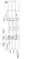
- the UE receives the PDCCH for scheduling the PUSCH transmission of CC # 2, the PDCCH for the scheduling of the PUSCH transmission of CC # 1, and CC # 0. It is assumed that PDCCHs for PUSCH transmission scheduling are detected in this order.
- the UE is a CC # 0 virtual PH (Virtual @ PH: VPH, PH based on the reference format), a CC # 1 virtual PH, and a CC # 2 real PH (Real @ PH: RPH, PH based on actual transmission). ) And can be calculated.
- the UE when PUSCH transmission of CC # 0, PUSCH transmission of CC # 1, and PUSCH transmission of CC # 2 are scheduled in the same time resource by these three PDCCHs as shown in FIG. 1B, the UE: It is conceivable to transmit data and PHR in the PUSCH transmission of CC # 2 based on the first DCI for PUSCH scheduling after the PHR is triggered. In this case, the UE does not consider the PUSCH transmission of CC # 0 and CC # 1 for the calculation of the PHR in the PUSCH transmission of CC # 2. For example, the UE may transmit a virtual PH of CC # 0, a virtual PH of CC # 1, and a real PH of CC # 2.
- the present inventors conceived PHR in PUSCH transmission of a plurality of cells (serving cells, CCs).
- the upper layer signaling includes, for example, RRC (Radio Resource Control) signaling, MAC (Medium Access Control) signaling (for example, MAC CE, MAC PDU (Protocol Data Data Unit)), broadcast information (master information block (MIB: Master Information Block)). Or a system information block (SIB: System @ Information @ Block), or a combination thereof.
- RRC Radio Resource Control
- MAC Medium Access Control
- MIB Master Information Block
- SIB System @ Information @ Block
- the UE may transmit the PHR on a dynamic grant PUSCH.
- the UE may calculate the correct PH and include it in the PUSCH. Let T be the time required for the UE to calculate the PH.
- the time domain resource allocation field (start and length indicator value, start and length indicator value: SLIV ) in DCI for scheduling PUSCH transmission when the slot offset K 2 indicated by indicating the above time T The UE may calculate the actual PH for the PUSCH transmission.
- the UE may send capability information on T to the base station. Thereby, the base station may schedule the PUSCH based on the capability information so that the actual PH is obtained.
- T may be a value defined in association with a terminal capability (for example, also referred to as UE @ processing @ capability, PUSCH @ timing @ capability) regarding the processing time of PDSCH / PUSCH.
- ⁇ Aspect 1-1> For the PUSCH transmitting the PHR, the PUSCH transmitted in a different cell that temporally overlaps the PUSCH, and the last DCI transmitted in the PDCCH (or DCI) that schedules these PUSCHs, If a predetermined processing time is secured between the PUSCH and the PUSCH, the actual PH calculated at the timing of the PUSCH transmitting the PHR may be reported.
- the predetermined processing time may be the T or a different value.
- the UE may perform this operation regardless of whether PUSCH transmissions on multiple CCs overlap in time.
- the UE may use the PDCCH for scheduling the PUSCH transmission of CC # 2, the PDCCH for the scheduling of the PUSCH transmission of CC # 1, and the PUSCH of CC # 0. It is assumed that PDCCHs for transmission scheduling are detected in this order. Also, it is assumed that PUSCH transmission of CC # 0, PUSCH transmission of CC # 1, and PUSCH transmission of CC # 2 are scheduled in the same time resource.
- the UE determines to transmit the CC # 0, CC # 1, and CC # 2 PHR in the PUSCH transmission of CC # 2 scheduled for the first UL grant after the PHR is triggered.
- the PUSCH transmitting the PHR may be the PUSCH having the lowest CC index (or cell index) among the PUSCHs, or may be the PUSCH of a predetermined CC (for example, PCell). , The PUSCH of any CC selected by the terminal.
- the UE can appropriately determine whether to calculate the actual PH based on the PUSCH scheduling. Further, even when the PUSCH is scheduled in a plurality of CCs after the PHR is triggered, the UE can appropriately determine the CC that transmits the PHR. Also, the UE can transmit a PHR corresponding to an actual situation by transmitting the PHRs for a plurality of CCs collectively.
- the UE may include a PUSCH transmitting the PHR and a PDCCH (or DCI) that schedules these PUSCHs for the PUSCH transmitted in the same or a different cell in the slot transmitting the PUSCH or a slot overlapping the slot. If a predetermined processing time is secured between the last transmitted DCI and the earliest PUSCH among these PUSCHs, the actual PH calculated at the timing of the PUSCH transmitting the PHR may be reported. Good.
- the predetermined processing time may be the T or a different value.
- the UE determines to transmit the PHRs of CC # 0, CC # 1, and CC # 2 in the earliest PUSCH transmission of CC # 0.
- the PHR transmitted from the PDCCH reception time interval between (CC # PUSCH transmission of 0) (t 0 of CC # 0, CC # 1 of t 1, CC # 2 of t 2) is not less than T. Therefore, the UE calculates the real PH of CC # 0, the real PH of CC # 1, and the real PH of CC # 2, and transmits the calculated PH in the PUSCH transmission of CC # 0.
- the PUSCH transmitting the PHR may be the PUSCH having the lowest CC index (or cell index) among the PUSCHs, or may be the PUSCH of a predetermined CC (for example, PCell). , The PUSCH of any CC selected by the terminal. Also, when there are a plurality of PUSCH transmissions in the corresponding slot of a predetermined CC, the UE may transmit the PHR in the earliest PUSCH transmission or may transmit the PHR in the latest PUSCH transmission.
- the UE can appropriately determine whether to calculate the actual PH based on the PUSCH scheduling. Further, even when the PUSCH is scheduled in a plurality of CCs after the PHR is triggered, the UE can appropriately determine the CC that transmits the PHR. In addition, in the earliest PUSCH transmission, the UE can transmit the PHRs for a plurality of CCs at the earliest possible timing by transmitting the PHRs for the plurality of CCs collectively.
- the UE may be configured for configured grant PUSCH transmission.
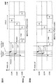
- the UE is configured to transmit the set grant PUSCH for CC # 2 and periodically performs the PUSCH transmission. Furthermore, it is assumed that after the PHR is triggered, the UE detects a PDCCH for scheduling the PUSCH transmission of CC # 1 and a PDCCH for scheduling the PUSCH transmission of CC # 0 in this order. Thereafter, in the same time resource, the set grant PUSCH transmission of CC # 2 and the dynamic grant (dynamic @ grant) PUSCH transmission of CC # 1 are performed, and then the dynamic grant PUSCH transmission of CC # 0 is performed. .
- the present inventors conceived the relationship between the set grant PUSCH transmission and the PHR.
- the UE may not report the PH on the configuration grant PUSCH.
- the UE may not report PH on the configuration grant PUSCH, even if the configuration grant PUSCH is the first PUSCH transmission after triggering the PHR. Also, even if the PHR prohibition timer (phrProhibitTimer) has expired at the transmission timing of the set grant PUSCH, the UE does not have to report the PH in the set grant PUSCH.
- the UE may not consider the configuration grant PUSCH in the PH calculation. For example, the UE may always calculate the virtual PH for the configuration grant PUSCH.
- ⁇ Aspect 2-1-2 If the time interval between the PDCCH that schedules the PUSCH carrying the PHR and the configured grant PUSCH transmission is greater than or equal to T, the UE may consider the configured grant PUSCH transmission in the PH calculation (for the configured grant PUSCH transmission). The actual PH may be calculated).
- the processing is simplified, and the processing load on the UE and the base station can be reduced.
- the UE may transmit the PHR on the configuration grant PUSCH.
- the UE may transmit the PHR on the first PUSCH transmission after the PHR is triggered. If the configured grant PUSCH transmission is the first PUSCH transmission after the PHR is triggered, and if the TB size of the configured grant PUSCH transmission is sufficient to carry the PHR, the UE may perform PHR in the configured grant PUSCH transmission. May be transmitted.
- the UE transmits a PHR on the configured grant PUSCH instead, the PHR may be transmitted in the next dynamic grant PUSCH transmission.
- the UE may calculate the actual PH as the PH for the PUSCH of a CC other than the CC carrying the PHR. If the time interval between the UL grant and the PUSCH carrying the PHR is smaller than T, the UE may calculate the virtual PH as the PH for the PUSCH of a CC other than the CC carrying the PHR.
- the UE may calculate the actual PH as the PH for the set grant PUSCH. If the time interval between triggering the PHR and transmitting the set grant PUSCH carrying the PHR is smaller than T, the UE may calculate the virtual PH as the PH for the set grant PUSCH.
- the UE calculates the actual PH for the PUSCH transmission of CC # 1.
- the UE reports the actual PH of CC # 0, the actual PH of CC # 1, and the actual PH of CC # 2 in CC # 2.
- the UE calculates a virtual PH for PUSCH transmission of CC # 0.
- the UE calculates a virtual PH for the PUSCH transmission of CC # 1.
- the UE calculates the actual PH for the CC # 2 set grant PUSCH transmission.
- the UE reports the virtual PH of CC # 0, the virtual PH of CC # 1, and the real PH of CC # 2 in CC # 2.
- the configured grant PUSCH transmission is the first PUSCH transmission after the PHR is triggered and overlaps with the dynamic grant PUSCH transmission of another CC, whether to transmit the PHR in the configured grant PUSCH transmission is determined by the UE implementation ( implementation / selection.
- the UE may not transmit the PHR in the configured grant PUSCH transmission Good.
- the UE may calculate the PH of CCs # 0 to # 2 in the same manner as in aspect 2-1.
- the UE may calculate the real PH of CC # 1, the real PH of CC # 2, and the virtual PH of CC # 0 in the same manner as in aspect 2-1-2.
- the UE may carry one PHR from the first plurality of PUSCH transmissions after the PHR is triggered, based on at least one of timing of a corresponding PDCCH, cell index, and whether or not a dynamic grant PUSCH transmission.
- PUSCH transmission may be determined. For example, the UE may select a dynamic grant PUSCH transmission scheduled by the earliest PDCCH after the PHR is triggered out of a plurality of initial PUSCH transmissions. The UE may select the PUSCH transmission corresponding to the smallest cell index from the plurality of first PUSCH transmissions. The UE may select a dynamic grant PUSCH transmission among a plurality of initial PUSCH transmissions. The UE may select a configuration grant PUSCH transmission among a plurality of first PUSCH transmissions.
- the UE may calculate the actual PH as the PH for the PUSCH of a CC other than the CC carrying the PHR. If the time interval between the UL grant and the PUSCH carrying the PHR is smaller than T, the UE may calculate the virtual PH as the PH for the PUSCH of a CC other than the CC carrying the PHR.
- the UE may transmit the PHR in the configured grant PUSCH transmission .
- the UE can flexibly determine the PUSCH transmission for transmitting the PHR.
- the UE may determine the real PH or the virtual PH based on the type of the configuration grant PUSCH.
- Type 1 PUSCH transmission with configured grant Type 1 configuration grant PUSCH transmission
- Type 1 configuration grant PUSCH transmission is configured by higher layer signaling and does not require activation.
- the UE may calculate the PH for Type 2 PUSCH transmission with configuration grant (Type 2 PUSCH transmission with configured grant, Type 2 configuration grant PUSCH transmission) as follows.
- Type 2 configuration grant PUSCH transmission is configured by higher layer signaling and requires activation.
- the UE may always transmit the first type 2 setting grant PUSCH transmission regardless of the presence or absence of the uplink data or the PHR. Therefore, in the first type-2 setting grant PUSCH transmission, the UE performs an operation close to the dynamic grant PUSCH transmission. Further, in transmission of the type 2 setting grant PUSCH other than the first type 2 setting grant PUSCH transmission, the UE performs an operation similar to the type 1 setting grant PUSCH transmission.
- the UE may calculate the actual PH as the PH for the first Type 2 PUSCH transmission after receiving the activation DCI.
- wireless communication system Wireless communication system
- communication is performed using any of the wireless communication methods according to the above embodiments of the present disclosure or a combination thereof.
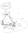
- FIG. 8 is a diagram illustrating an example of a schematic configuration of a wireless communication system according to an embodiment.
- carrier aggregation (CA) and / or dual connectivity (DC) in which a plurality of basic frequency blocks (component carriers) each having a system bandwidth (for example, 20 MHz) of the LTE system as one unit are applied. can do.
- DC dual connectivity
- the wireless communication system 1 includes LTE (Long Term Evolution), LTE-A (LTE-Advanced), LTE-B (LTE-Beyond), SUPER 3G, IMT-Advanced, 4G (4th generation mobile communication system), and 5G. (5th generation mobile communication system), NR (New Radio), FRA (Future Radio Access), New-RAT (Radio Access Technology), etc., or a system for realizing these.
- LTE Long Term Evolution
- LTE-A LTE-Advanced
- LTE-B LTE-Beyond
- SUPER 3G IMT-Advanced
- 4G 4th generation mobile communication system
- 5G 5th generation mobile communication system
- NR New Radio
- FRA Full Radio Access
- New-RAT Radio Access Technology
- the wireless communication system 1 includes a base station 11 forming a macro cell C1 having relatively wide coverage, and a base station 12 (12a to 12c) arranged in the macro cell C1 and forming a small cell C2 smaller than the macro cell C1.
- a base station 11 forming a macro cell C1 having relatively wide coverage
- a base station 12 (12a to 12c) arranged in the macro cell C1 and forming a small cell C2 smaller than the macro cell C1.
- user terminals 20 are arranged in the macro cell C1 and each small cell C2.
- the arrangement, number, and the like of each cell and the user terminals 20 are not limited to the modes shown in the figure.
- a communication between the user terminal 20 and the base station 11 can be performed using a carrier having a relatively low frequency band (for example, 2 GHz) and a narrow bandwidth (also referred to as an existing carrier or a legacy carrier).
- a carrier having a relatively high frequency band for example, 3.5 GHz, 5 GHz or the like
- a wide bandwidth may be used, or between the user terminal 20 and the base station 11.
- the same carrier as described above may be used.
- the configuration of the frequency band used by each base station is not limited to this.
- the user terminal 20 can perform communication using time division duplex (TDD: Time Division Duplex) and / or frequency division duplex (FDD: Frequency Division Duplex) in each cell.
- TDD Time Division Duplex
- FDD Frequency Division Duplex
- a single numerology may be applied, or a plurality of different numerologies may be applied.
- the base station 11 and the base station 12 may be connected by a wire (for example, an optical fiber compliant with CPRI (Common Public Radio Interface), an X2 interface, or the like) or wirelessly. Good.
- a wire for example, an optical fiber compliant with CPRI (Common Public Radio Interface), an X2 interface, or the like
- CPRI Common Public Radio Interface
- X2 interface or the like
- the base station 11 and each base station 12 are connected to the upper station device 30 and are connected to the core network 40 via the upper station device 30.
- the higher station apparatus 30 includes, for example, an access gateway apparatus, a radio network controller (RNC), and a mobility management entity (MME), but is not limited thereto.
- RNC radio network controller
- MME mobility management entity
- each base station 12 may be connected to the upper station device 30 via the base station 11.
- Each user terminal 20 is a terminal corresponding to various communication systems such as LTE and LTE-A, and may include not only mobile communication terminals (mobile stations) but also fixed communication terminals (fixed stations).
- PCFICH transmits the number of OFDM symbols used for PDCCH.
- the PHICH transmits acknowledgment information (for example, retransmission control information, HARQ-ACK, ACK / NACK, etc.) of HARQ (Hybrid Automatic Repeat Repeat request) for the PUSCH.
- the EPDCCH is frequency-division multiplexed with a PDSCH (Downlink Shared Data Channel) and used for transmission of DCI and the like like the PDCCH.
- PDSCH Downlink Shared Data Channel
- a cell-specific reference signal CRS: Cell-specific Reference Signal
- CSI-RS Channel State Information-Reference Signal
- DMRS Demodulation Reference Signal
- PRS Positioning Reference Signal
- a measurement reference signal SRS: Sounding Reference Signal
- DMRS demodulation reference signal
- PRS Positioning Reference Signal
- the transmitted reference signal is not limited to these.
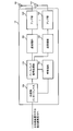
- FIG. 9 is a diagram illustrating an example of the entire configuration of the base station according to the embodiment.
- the base station 10 includes a plurality of transmitting / receiving antennas 101, an amplifier unit 102, a transmitting / receiving unit 103, a baseband signal processing unit 104, a call processing unit 105, and a transmission path interface 106.
- the transmitting / receiving antenna 101, the amplifier unit 102, and the transmitting / receiving unit 103 may be configured to include at least one each.
- the baseband signal processing unit 104 regarding user data, processing of a PDCP (Packet Data Convergence Protocol) layer, division / combination of user data, transmission processing of an RLC layer such as RLC (Radio Link Control) retransmission control, and MAC (Medium Access) Control)
- the transmission / reception unit performs retransmission control (for example, HARQ transmission processing), scheduling, transmission format selection, channel coding, inverse fast Fourier transform (IFFT) processing, precoding processing, and so on.
- HARQ transmission processing for example, HARQ transmission processing
- IFFT inverse fast Fourier transform
- precoding processing precoding processing
- the downlink control signal is also subjected to transmission processing such as channel coding and inverse fast Fourier transform, and transferred to the transmission / reception unit 103.
- the transmission / reception section 103 converts the baseband signal output from the baseband signal processing section 104 after precoding for each antenna into a radio frequency band, and transmits the radio frequency band.
- the radio frequency signal frequency-converted by the transmitting / receiving section 103 is amplified by the amplifier section 102 and transmitted from the transmitting / receiving antenna 101.
- the transmission / reception unit 103 can be configured from a transmitter / receiver, a transmission / reception circuit, or a transmission / reception device described based on common recognition in the technical field according to the present disclosure. Note that the transmission / reception unit 103 may be configured as an integrated transmission / reception unit, or may be configured from a transmission unit and a reception unit.
- fast Fourier transform FFT: Fast Fourier Transform
- IDFT inverse discrete Fourier transform
- error correction is performed on user data included in the input uplink signal.
- Decoding, reception processing of MAC retransmission control, reception processing of the RLC layer and PDCP layer are performed, and the data is transferred to the upper station apparatus 30 via the transmission path interface 106.
- the call processing unit 105 performs call processing (setting, release, etc.) of a communication channel, state management of the base station 10, management of radio resources, and the like.
- the transmission path interface 106 transmits and receives signals to and from the higher-level station device 30 via a predetermined interface.
- the transmission line interface 106 transmits and receives signals (backhaul signaling) to and from another base station 10 via an interface between base stations (for example, an optical fiber compliant with CPRI (Common Public Radio Interface), an X2 interface). Is also good.
- CPRI Common Public Radio Interface
- X2 interface X2 interface
- the transmitting / receiving section 103 may receive a plurality of uplink shared channel transmissions corresponding to a plurality of cells, respectively.
- the baseband signal processing unit 104 includes at least a control unit (scheduler) 301, a transmission signal generation unit 302, a mapping unit 303, a reception signal processing unit 304, and a measurement unit 305. Note that these configurations need only be included in base station 10, and some or all of the configurations need not be included in baseband signal processing section 104.
- the control unit (scheduler) 301 controls the entire base station 10.
- the control unit 301 can be configured from a controller, a control circuit, or a control device described based on common recognition in the technical field according to the present disclosure.
- the control unit 301 controls, for example, signal generation in the transmission signal generation unit 302, signal assignment in the mapping unit 303, and the like. Further, the control unit 301 controls a signal reception process in the reception signal processing unit 304, a signal measurement in the measurement unit 305, and the like.
- the control unit 301 performs scheduling (for example, resources) of system information, a downlink data signal (for example, a signal transmitted on the PDSCH), and a downlink control signal (for example, a signal transmitted on the PDCCH and / or the EPDCCH; acknowledgment information and the like). Allocation). Further, control section 301 controls generation of a downlink control signal, a downlink data signal, and the like based on a result of determining whether or not retransmission control is required for an uplink data signal.
- scheduling for example, resources
- a downlink data signal for example, a signal transmitted on the PDSCH
- a downlink control signal for example, a signal transmitted on the PDCCH and / or the EPDCCH; acknowledgment information and the like. Allocation.
- control section 301 controls generation of a downlink control signal, a downlink data signal, and the like based on a result of determining whether or not retransmission control is required for an uplink data signal.
- the control unit 301 controls scheduling of a synchronization signal (for example, Primary Synchronization Signal (PSS) / Secondary Synchronization Signal (SSS)) and a downlink reference signal (for example, CRS, CSI-RS, DMRS).
- a synchronization signal for example, Primary Synchronization Signal (PSS) / Secondary Synchronization Signal (SSS)
- SSS Secondary Synchronization Signal
- CRS channel CSI-RS
- DMRS Downlink reference signal
- the control unit 301 includes an uplink data signal (for example, a signal transmitted on PUSCH), an uplink control signal (for example, a signal transmitted on PUCCH and / or PUSCH, acknowledgment information, etc.), a random access preamble (for example, PRACH). (Transmission signal), scheduling of uplink reference signals and the like.
- an uplink data signal for example, a signal transmitted on PUSCH
- an uplink control signal for example, a signal transmitted on PUCCH and / or PUSCH, acknowledgment information, etc.
- a random access preamble for example, PRACH.
- Transmission signal scheduling of uplink reference signals and the like.
- Transmission signal generation section 302 generates a downlink signal (downlink control signal, downlink data signal, downlink reference signal, etc.) based on an instruction from control section 301, and outputs the generated downlink signal to mapping section 303.
- the transmission signal generation unit 302 can be configured from a signal generator, a signal generation circuit, or a signal generation device described based on common recognition in the technical field according to the present disclosure.
- the transmission signal generation unit 302 generates a DL assignment for notifying downlink data allocation information and / or a UL grant for notifying uplink data allocation information, based on an instruction from the control unit 301, for example.
- the DL assignment and the UL grant are both DCI and follow the DCI format.
- the downlink data signal is subjected to an encoding process and a modulation process according to an encoding rate, a modulation scheme, and the like determined based on channel state information (CSI: Channel ⁇ State ⁇ Information) from each user terminal 20 and the like.
- CSI Channel ⁇ State ⁇ Information
- Mapping section 303 maps the downlink signal generated by transmission signal generating section 302 to a predetermined radio resource based on an instruction from control section 301, and outputs it to transmitting / receiving section 103.
- the mapping unit 303 can be configured from a mapper, a mapping circuit, or a mapping device described based on common recognition in the technical field according to the present disclosure.
- the reception signal processing unit 304 performs reception processing (for example, demapping, demodulation, decoding, and the like) on the reception signal input from the transmission / reception unit 103.
- the received signal is, for example, an uplink signal (uplink control signal, uplink data signal, uplink reference signal, etc.) transmitted from the user terminal 20.
- the reception signal processing unit 304 can be configured from a signal processor, a signal processing circuit, or a signal processing device described based on common recognition in the technical field according to the present disclosure.
- the measurement unit 305 may perform RRM (Radio Resource Management) measurement, CSI (Channel State Information) measurement, or the like based on the received signal.
- the measurement unit 305 is configured to receive power (for example, RSRP (Reference Signal Received Power)), reception quality (for example, RSRQ (Reference Signal Received Quality), SINR (Signal to Interference plus Noise Ratio, SNR (Signal to Noise Ratio)). , Signal strength (for example, RSSI (Received @ Signal @ Strength @ Indicator)), channel information (for example, CSI), and the like.
- the measurement result may be output to the control unit 301.
- FIG. 11 is a diagram illustrating an example of the overall configuration of the user terminal according to the embodiment.
- the user terminal 20 includes a plurality of transmitting / receiving antennas 201, an amplifier unit 202, a transmitting / receiving unit 203, a baseband signal processing unit 204, and an application unit 205.
- the transmitting / receiving antenna 201, the amplifier unit 202, and the transmitting / receiving unit 203 may be configured to include at least one each.
- the radio frequency signal received by the transmitting / receiving antenna 201 is amplified by the amplifier unit 202.
- the transmission / reception unit 203 receives the downlink signal amplified by the amplifier unit 202.
- the transmission / reception section 203 converts the frequency of the received signal into a baseband signal, and outputs the baseband signal to the baseband signal processing section 204.
- the transmission / reception unit 203 can be configured from a transmitter / receiver, a transmission / reception circuit, or a transmission / reception device described based on common recognition in the technical field according to the present disclosure. Note that the transmission / reception unit 203 may be configured as an integrated transmission / reception unit, or may be configured from a transmission unit and a reception unit.
- the baseband signal processing unit 204 performs FFT processing, error correction decoding, reception processing for retransmission control, and the like on the input baseband signal.
- the downlink user data is transferred to the application unit 205.
- the application unit 205 performs processing related to layers higher than the physical layer and the MAC layer. Also, of the downlink data, broadcast information may be transferred to the application unit 205.
- uplink user data is input from the application unit 205 to the baseband signal processing unit 204.
- the baseband signal processing unit 204 performs retransmission control transmission processing (eg, HARQ transmission processing), channel coding, precoding, discrete Fourier transform (DFT) processing, IFFT processing, and the like, and performs transmission / reception processing. Transferred to 203.
- the transmission / reception unit 203 converts the baseband signal output from the baseband signal processing unit 204 into a radio frequency band and transmits the radio frequency band.
- the radio frequency signal frequency-converted by the transmitting / receiving section 203 is amplified by the amplifier section 202 and transmitted from the transmitting / receiving antenna 201.
- the transmission / reception unit 203 may also perform a plurality of uplink shared channel (PUSCH) transmissions (dynamic grant PUSCH transmission or set grant PUSCH transmission) corresponding to a plurality of cells (CCs).
- PUSCH uplink shared channel
- the baseband signal processing unit 204 of the user terminal 20 includes at least a control unit 401, a transmission signal generation unit 402, a mapping unit 403, a reception signal processing unit 404, and a measurement unit 405. Note that these configurations need only be included in the user terminal 20, and some or all of the configurations need not be included in the baseband signal processing unit 204.
- the control unit 401 controls the entire user terminal 20.
- the control unit 401 can be configured by a controller, a control circuit, or a control device described based on common recognition in the technical field according to the present disclosure.
- Transmission signal generating section 402 generates an uplink signal (uplink control signal, uplink data signal, uplink reference signal, etc.) based on an instruction from control section 401 and outputs the generated signal to mapping section 403.
- the transmission signal generation unit 402 can be configured from a signal generator, a signal generation circuit, or a signal generation device described based on common recognition in the technical field according to the present disclosure.
- the transmission signal generation unit 402 generates an uplink control signal related to acknowledgment information, channel state information (CSI), and the like, based on an instruction from the control unit 401, for example. Further, transmission signal generating section 402 generates an uplink data signal based on an instruction from control section 401. For example, the transmission signal generation unit 402 is instructed by the control unit 401 to generate an uplink data signal when the downlink control signal notified from the base station 10 includes a UL grant.
- CSI channel state information
- Mapping section 403 maps the uplink signal generated by transmission signal generation section 402 to a radio resource based on an instruction from control section 401, and outputs the result to transmission / reception section 203.
- the mapping unit 403 can be configured from a mapper, a mapping circuit, or a mapping device described based on common recognition in the technical field according to the present disclosure.
- the reception signal processing unit 404 performs reception processing (for example, demapping, demodulation, and decoding) on the reception signal input from the transmission / reception unit 203.
- the received signal is, for example, a downlink signal (a downlink control signal, a downlink data signal, a downlink reference signal, etc.) transmitted from the base station 10.
- the reception signal processing unit 404 can be configured from a signal processor, a signal processing circuit, or a signal processing device described based on common recognition in the technical field according to the present disclosure.
- the reception signal processing unit 404 can configure a reception unit according to the present disclosure.
- the reception signal processing unit 404 outputs the information decoded by the reception processing to the control unit 401.
- the reception signal processing unit 404 outputs, for example, broadcast information, system information, RRC signaling, DCI, and the like to the control unit 401. Further, the reception signal processing unit 404 outputs the reception signal and / or the signal after the reception processing to the measurement unit 405.
- the measurement unit 405 performs measurement on the received signal.
- the measurement unit 405 can be configured from a measurement device, a measurement circuit, or a measurement device described based on common recognition in the technical field according to the present disclosure.
- the measurement unit 405 may perform RRM measurement, CSI measurement, and the like based on the received signal.
- the measurement unit 405 may measure reception power (for example, RSRP), reception quality (for example, RSRQ, SINR, SNR), signal strength (for example, RSSI), channel information (for example, CSI), and the like.
- the measurement result may be output to the control unit 401.
- control unit 401 determines that the processing time of each of the plurality of PHs (the time required for calculating the PH, capability information) and that each of the plurality of uplink shared channel transmissions is a set grant uplink shared channel transmission. And determining whether the plurality of PHs are based on actual plurality of uplink shared channel transmissions (whether real or virtual PH, based on actual transmissions or based on a reference format) based on at least one of: You may.
- control unit 401 determines the timing of the downlink shared channel for scheduling the uplink shared channel transmission (for example, the earliest PDCCH after the PHR trigger) and the timing of the uplink shared channel transmission (for example, the most recent after the PHR trigger).
- the uplink shared channel transmission used for the report may be determined based on at least one of the early PUSCH) and whether each of the plurality of uplink shared channel transmissions is a configured grant uplink shared channel transmission.
- the control unit 401 may determine the uplink shared channel transmission used for the report based on the size of the set grant uplink shared channel transmission (for example, the TB size).
- control unit 401 when the plurality of uplink shared channel transmissions overlap in time, and includes dynamic grant uplink shared channel transmission and set grant uplink shared channel transmission, the dynamic grant uplink shared channel transmission and the A plurality of power headrooms (PH) respectively corresponding to the plurality of cells may be reported in one uplink shared channel transmission of a predetermined type among the set grant uplink shared channel transmissions.
- PH power headrooms
- the predetermined type may be the dynamic grant uplink shared channel transmission.
- the predetermined type may be the set grant uplink shared channel transmission.
- each functional block may be realized using one device physically or logically coupled, or directly or indirectly (for example, two or more devices physically or logically separated from each other). , Wired, wireless, etc.) and using these multiple devices.
- the functional block may be realized by combining one device or the plurality of devices with software.
- the functions include judgment, decision, judgment, calculation, calculation, processing, derivation, investigation, search, confirmation, reception, transmission, output, access, resolution, selection, selection, establishment, comparison, assumption, expectation, and deemed. , Broadcasting, notifying, communicating, forwarding, configuring, reconfiguring, allocating, mapping, assigning, etc.
- a functional block that makes transmission function may be referred to as a transmitting unit (transmitting unit), a transmitter (transmitter), or the like.
- the realization method is not particularly limited.
- a base station, a user terminal, and the like may function as a computer that performs processing of the wireless communication method according to the present disclosure.
- FIG. 13 is a diagram illustrating an example of a hardware configuration of the base station and the user terminal according to the embodiment.
- the above-described base station 10 and user terminal 20 may be physically configured as a computer device including a processor 1001, a memory 1002, a storage 1003, a communication device 1004, an input device 1005, an output device 1006, a bus 1007, and the like. .
- the term “apparatus” can be read as a circuit, a device, a unit, or the like.
- the hardware configuration of the base station 10 and the user terminal 20 may be configured to include one or more of the devices illustrated in the drawing, or may be configured to exclude some of the devices.
- processor 1001 may be implemented by one or more chips.
- the processor 1001 controls the entire computer by operating an operating system, for example.
- the processor 1001 may be configured by a central processing unit (CPU: Central Processing Unit) including an interface with a peripheral device, a control device, an arithmetic device, a register, and the like.
- CPU Central Processing Unit
- the above-described baseband signal processing unit 104 (204), call processing unit 105, and the like may be realized by the processor 1001.
- the storage 1003 is a computer-readable recording medium such as a flexible disk, a floppy (registered trademark) disk, a magneto-optical disk (for example, a compact disk (CD-ROM (Compact Disc) ROM, etc.)), a digital versatile disc, At least one of a Blu-ray (registered trademark) disk, a removable disk, a hard disk drive, a smart card, a flash memory device (eg, a card, a stick, a key drive), a magnetic stripe, a database, a server, and other suitable storage media. May be configured.
- the storage 1003 may be called an auxiliary storage device.
- the communication device 1004 is hardware (transmission / reception device) for performing communication between computers via at least one of a wired network and a wireless network, and is also referred to as, for example, a network device, a network controller, a network card, a communication module, or the like.
- the communication device 1004 includes, for example, a high-frequency switch, a duplexer, a filter, a frequency synthesizer, and the like in order to realize at least one of frequency division duplex (FDD: Frequency Division Duplex) and time division duplex (TDD: Time Division Duplex). May be configured.
- FDD Frequency Division Duplex
- TDD Time Division Duplex
- the transmission / reception antenna 101 (201), the amplifier unit 102 (202), the transmission / reception unit 103 (203), the transmission line interface 106, and the like may be realized by the communication device 1004.
- the transmission / reception unit 103 may be physically or logically separated by the transmission unit 103a and the reception unit 103b.
- the input device 1005 is an input device (for example, a keyboard, a mouse, a microphone, a switch, a button, a sensor, and the like) that receives an external input.
- the output device 1006 is an output device that performs output to the outside (for example, a display, a speaker, an LED (Light Emitting Diode) lamp, and the like). Note that the input device 1005 and the output device 1006 may have an integrated configuration (for example, a touch panel).
- the devices such as the processor 1001 and the memory 1002 are connected by a bus 1007 for communicating information.
- the bus 1007 may be configured using a single bus, or may be configured using a different bus for each device.
- the base station 10 and the user terminal 20 include hardware such as a microprocessor, a digital signal processor (DSP), an ASIC (Application Specific Integrated Circuit), a PLD (Programmable Logic Device), and an FPGA (Field Programmable Gate Array). It may be configured to include hardware, and some or all of the functional blocks may be realized using the hardware.
- the processor 1001 may be implemented using at least one of these hardware.
- the radio frame may be configured by one or a plurality of periods (frames) in the time domain.
- the one or more respective periods (frames) forming the radio frame may be referred to as a subframe.
- a subframe may be configured by one or more slots in the time domain.
- the subframe may be of a fixed length of time (eg, 1 ms) that does not depend on numerology.
- the new melology may be a communication parameter applied to at least one of transmission and reception of a certain signal or channel.
- Numerology includes, for example, subcarrier interval (SCS: SubCarrier @ Spacing), bandwidth, symbol length, cyclic prefix length, transmission time interval (TTI: Transmission @ Time @ Interval), number of symbols per TTI, radio frame configuration, transmission and reception.
- SCS SubCarrier @ Spacing
- TTI Transmission @ Time @ Interval
- TTI Transmission @ Time @ Interval
- radio frame configuration transmission and reception.
- At least one of a specific filtering process performed by the transceiver in the frequency domain and a specific windowing process performed by the transceiver in the time domain may be indicated.
- the slot may be configured by one or more symbols (OFDM (Orthogonal Frequency Division Multiplexing) symbol, SC-FDMA (Single Carrier Frequency Division Multiple Access) symbol, etc.) in the time domain. Further, the slot may be a time unit based on numerology.
- OFDM Orthogonal Frequency Division Multiplexing
- SC-FDMA Single Carrier Frequency Division Multiple Access
- the slot may include a plurality of mini slots.
- Each minislot may be constituted by one or more symbols in the time domain.
- minislots may be called subslots.
- a minislot may be made up of a smaller number of symbols than slots.
- a PDSCH (or PUSCH) transmitted in time units larger than minislots may be referred to as PDSCH (PUSCH) mapping type A.
- a PDSCH (or PUSCH) transmitted using minislots may be referred to as PDSCH (PUSCH) mapping type B.
- Radio frames, subframes, slots, minislots, and symbols all represent time units when transmitting signals.
- the radio frame, the subframe, the slot, the minislot, and the symbol may have different names corresponding thereto. Note that time units such as frames, subframes, slots, minislots, and symbols in the present disclosure may be interchanged with each other.
- one subframe may be called a transmission time interval (TTI: Transmission @ Time @ Interval)
- TTI Transmission @ Time @ Interval
- TTI Transmission Time interval
- TTI Transmission @ Time @ Interval
- TTI Transmission Time interval
- TTI Transmission @ Time @ Interval
- TTI Transmission Time interval
- TTI Transmission @ Time @ Interval
- TTI Transmission Time interval
- TTI Transmission @ Time @ Interval
- TTI Transmission Time interval
- TTI Transmission @ Time @ Interval
- one slot or one minislot is called a TTI.
- TTI means, for example, a minimum time unit of scheduling in wireless communication.
- the base station performs scheduling for allocating radio resources (frequency bandwidth, transmission power, and the like that can be used in each user terminal) to each user terminal in TTI units.
- radio resources frequency bandwidth, transmission power, and the like that can be used in each user terminal
- the TTI may be a transmission time unit such as a channel-encoded data packet (transport block), a code block, a code word, or a processing unit such as scheduling and link adaptation. Note that when a TTI is given, a time section (for example, the number of symbols) in which a transport block, a code block, a codeword, and the like are actually mapped may be shorter than the TTI.
- one slot or one minislot is called a TTI
- one or more TTIs may be the minimum time unit for scheduling. Further, the number of slots (mini-slot number) constituting the minimum time unit of the scheduling may be controlled.
- a TTI having a time length of 1 ms may be called a normal TTI (TTI in LTE@Rel.8-12), a normal TTI, a long TTI, a normal subframe, a normal subframe, a long subframe, a slot, and the like.
- a TTI shorter than the normal TTI may be called a shortened TTI, a short TTI, a partial TTI (partial or fractional TTI), a shortened subframe, a short subframe, a minislot, a subslot, a slot, and the like.
- a long TTI (for example, a normal TTI, a subframe, etc.) may be read as a TTI having a time length exceeding 1 ms, and a short TTI (for example, a shortened TTI, etc.) may be replaced with a TTI shorter than the long TTI and 1 ms.
- the TTI having the TTI length described above may be replaced with the TTI.
- the resource block (RB: Resource Block) is a resource allocation unit in the time domain and the frequency domain, and may include one or a plurality of continuous subcarriers (subcarriers) in the frequency domain.
- the number of subcarriers included in the RB may be the same irrespective of the numerology, and may be, for example, 12.
- the number of subcarriers included in the RB may be determined based on numerology.
- the RB may include one or more symbols in the time domain, and may have a length of one slot, one minislot, one subframe, or one TTI.
- One TTI, one subframe, and the like may each be configured by one or a plurality of resource blocks.
- one or a plurality of RBs include a physical resource block (PRB: Physical @ RB), a subcarrier group (SCG: Sub-Carrier @ Group), a resource element group (REG: Resource @ Element @ Group), a PRB pair, an RB pair, and the like. May be called.
- PRB Physical @ RB
- SCG Sub-Carrier @ Group
- REG Resource @ Element @ Group
- PRB pair an RB pair, and the like. May be called.
- a resource block may be composed of one or more resource elements (RE: Resource @ Element).
- RE Resource @ Element
- one RE may be a radio resource area of one subcarrier and one symbol.
- a bandwidth part (which may also be referred to as a partial bandwidth or the like) may represent a subset of contiguous common RBs (common @ resource @ blocks) for a certain numerology in a certain carrier. Good.
- the common RB may be specified by an index of the RB based on the common reference point of the carrier.
- a PRB may be defined in a BWP and numbered within the BWP.
- $ BWP may include a BWP for UL (UL @ BWP) and a BWP for DL (DL @ BWP).
- BWP for a UE, one or more BWPs may be configured in one carrier.
- At least one of the configured BWPs may be active, and the UE may not have to assume transmitting and receiving a given signal / channel outside the active BWP.
- “cell”, “carrier”, and the like in the present disclosure may be replaced with “BWP”.
- the structures of the above-described radio frame, subframe, slot, minislot, and symbol are merely examples.
- the number of subframes included in a radio frame, the number of slots per subframe or radio frame, the number of minislots included in a slot, the number of symbols and RBs included in a slot or minislot, included in an RB The number of subcarriers, the number of symbols in a TTI, the symbol length, the configuration such as the cyclic prefix (CP) length can be variously changed.
- the information, parameters, and the like described in the present disclosure may be represented using an absolute value, may be represented using a relative value from a predetermined value, or may be represented using another corresponding information. May be represented.
- a radio resource may be indicated by a predetermined index.
- Names used for parameters and the like in the present disclosure are not limited in any way. Further, the formulas and the like using these parameters may be different from those explicitly disclosed in the present disclosure.
- the various channels (PUCCH (Physical Uplink Control Channel), PDCCH (Physical Downlink Control Channel), etc.) and information elements can be identified by any suitable name, so the various names assigned to these various channels and information elements Is not a limiting name in any way.
- the information, signals, etc. described in this disclosure may be represented using any of a variety of different technologies.
- data, instructions, commands, information, signals, bits, symbols, chips, etc. that can be referred to throughout the above description are not limited to voltages, currents, electromagnetic waves, magnetic or magnetic particles, optical or photons, or any of these. May be represented by a combination of
- information, signals, etc. can be output from the upper layer to at least one of the lower layer and the lower layer to the upper layer.
- Information, signals, and the like may be input and output via a plurality of network nodes.
- Information and signals input and output may be stored in a specific location (for example, a memory) or may be managed using a management table. Information and signals that are input and output can be overwritten, updated, or added. The output information, signal, and the like may be deleted. The input information, signal, and the like may be transmitted to another device.
- Notification of information is not limited to the aspect / embodiment described in the present disclosure, and may be performed using another method.
- the information is notified by physical layer signaling (for example, downlink control information (DCI: Downlink Control Information), uplink control information (UCI: Uplink Control Information)), upper layer signaling (for example, RRC (Radio Resource Control) signaling, It may be implemented by broadcast information (master information block (MIB: Master Information Block), system information block (SIB: System Information Block), etc.), MAC (Medium Access Control) signaling), other signals, or a combination thereof.
- DCI Downlink Control Information
- UCI Uplink Control Information
- RRC Radio Resource Control
- MIB Master Information Block
- SIB System Information Block
- MAC Medium Access Control
- the notification of the predetermined information is not limited to an explicit notification, and is implicit (for example, by not performing the notification of the predetermined information or by another information). May be performed).
- the determination may be made by a value represented by 1 bit (0 or 1) or by a boolean value represented by true or false. , May be performed by comparing numerical values (for example, comparison with a predetermined value).
- Software whether called software, firmware, middleware, microcode, hardware description language, or any other name, instructions, instruction sets, codes, code segments, program codes, programs, subprograms, software modules , Applications, software applications, software packages, routines, subroutines, objects, executables, threads of execution, procedures, functions, and the like.
- system and “network” may be used interchangeably.
- base station (BS: Base @ Station)”, “wireless base station”, “fixed station (fixed @ station)”, “NodeB”, “eNodeB (eNB)”, “gNodeB (gNB)”, “ “Access point (access @ point)”, “transmission point (TP: Transmission @ Point)”, “reception point (RP: Reception @ Point)”, “transmission / reception point (TRP: Transmission / Reception @ Point)", “panel”, “cell” Terms such as, “sector”, “cell group”, “carrier”, “component carrier” may be used interchangeably.
- a base station may be referred to by a term such as a macro cell, a small cell, a femto cell, a pico cell, and the like.
- a base station can accommodate one or more (eg, three) cells. If the base station accommodates multiple cells, the entire coverage area of the base station can be partitioned into multiple smaller areas, each smaller area being a base station subsystem (eg, a small indoor base station (RRH: Communication services can also be provided by Remote Radio ⁇ Head)).
- a base station subsystem eg, a small indoor base station (RRH: Communication services can also be provided by Remote Radio ⁇ Head).
- RRH Small indoor base station
- the term “cell” or “sector” refers to part or all of the coverage area of at least one of a base station and a base station subsystem that provides communication services in this coverage.
- MS mobile station
- UE user equipment
- terminal terminal
- a mobile station is a subscriber station, mobile unit, subscriber unit, wireless unit, remote unit, mobile device, wireless device, wireless communication device, remote device, mobile subscriber station, access terminal, mobile terminal, wireless terminal, remote terminal. , A handset, a user agent, a mobile client, a client or some other suitable terminology.
- At least one of the base station and the mobile station may be called a transmitting device, a receiving device, a communication device, or the like.
- at least one of the base station and the mobile station may be a device mounted on the mobile unit, the mobile unit itself, or the like.
- the moving object may be a vehicle (for example, a car, an airplane, etc.), an unmanned moving object (for example, a drone, a self-driving car, etc.), or a robot (maned or unmanned). ).
- at least one of the base station and the mobile station includes a device that does not necessarily move during a communication operation.
- at least one of the base station and the mobile station may be an IoT (Internet of Things) device such as a sensor.
- IoT Internet of Things
- the base station in the present disclosure may be replaced with a user terminal.
- communication between a base station and a user terminal is replaced with communication between a plurality of user terminals (for example, it may be called D2D (Device-to-Device), V2X (Vehicle-to-Everything), etc.).
- D2D Device-to-Device
- V2X Vehicle-to-Everything
- each aspect / embodiment of the present disclosure may be applied.
- the configuration may be such that the user terminal 20 has the function of the base station 10 described above.
- words such as “up” and “down” may be read as words corresponding to communication between terminals (for example, “side”).
- an uplink channel, a downlink channel, and the like may be replaced with a side channel.
- the user terminal in the present disclosure may be replaced with a base station.
- the base station 10 may have the function of the user terminal 20 described above.
- an operation performed by the base station may be performed by an upper node (upper node) in some cases.
- various operations performed for communication with a terminal include a base station, one or more network nodes other than the base station (eg, Obviously, it can be performed by MME (Mobility @ Management @ Entity), S-GW (Serving-Gateway), etc., but not limited thereto, or a combination thereof.
- Each aspect / embodiment described in the present disclosure may be used alone, may be used in combination, or may be switched and used in execution.
- the order of the processing procedure, sequence, flowchart, and the like of each aspect / embodiment described in the present disclosure may be changed as long as there is no inconsistency.
- elements of the various steps are presented in an exemplary order, and are not limited to the specific order presented.
- LTE Long Term Evolution
- LTE-A Long Term Evolution
- LTE-B Long Term Evolution-Beyond
- SUPER 3G IMT-Advanced
- 4G 4th generation mobile communication
- system 5G (5th generation mobile communication system)
- FRA Fluture Radio Access
- New-RAT Radio Access Technology
- NR New Radio
- NX New radio access
- FX Fluture generation radio access
- GSM Registered trademark
- CDMA2000 Code Division Multiple Access
- UMB Ultra Mobile Broadband
- IEEE 802.11 Wi-Fi (registered trademark)
- IEEE 802.16 WiMAX (registered trademark)
- UWB Ultra-WideBand
- Bluetooth registered trademark
- a system using other appropriate wireless communication methods a next-generation system extended based on these systems, and the like.
- a plurality of systems may be combined (for example, a combination of LTE or LTE-A and 5G) and applied.
- any reference to elements using designations such as "first,” “second,” etc., as used in this disclosure, does not generally limit the quantity or order of those elements. These designations may be used in the present disclosure as a convenient way to distinguish between two or more elements. Thus, reference to a first and second element does not mean that only two elements can be employed or that the first element must precede the second element in some way.
- determining means judging, calculating, computing, processing, deriving, investigating, searching (up, search, inquiry) ( For example, a search in a table, database, or another data structure), ascertaining, etc., may be regarded as "deciding".
- determination includes receiving (eg, receiving information), transmitting (eg, transmitting information), input (input), output (output), and access ( accessing) (e.g., accessing data in a memory) or the like.
- judgment (decision) is regarded as “judgment (decision)” of resolving, selecting, selecting, establishing, comparing, and the like. Is also good. That is, “judgment (decision)” may be regarded as “judgment (decision)” of any operation.
- “judgment (decision)” may be read as “assuming”, “expecting”, “considering”, or the like.
- the “maximum transmission power” described in the present disclosure may mean the maximum value of the transmission power, may mean the nominal maximum transmission power (the nominal UE maximum transmit power), or may refer to the rated maximum transmission power (the rated UE maximum transmit power).
- connection refers to any direct or indirect connection or coupling between two or more elements. And may include the presence of one or more intermediate elements between two elements “connected” or “coupled” to each other.
- the coupling or connection between the elements may be physical, logical, or a combination thereof. For example, “connection” may be read as “access”.
- the radio frequency domain, microwave It can be considered to be “connected” or “coupled” to each other using electromagnetic energy having a wavelength in the region, the light (both visible and invisible) regions, and the like.
- the term “A and B are different” may mean that “A and B are different from each other”.
- the term may mean that “A and B are different from C”.
- Terms such as “separate” and “coupled” may be construed similarly to “different.”
Landscapes
- Engineering & Computer Science (AREA)
- Computer Networks & Wireless Communication (AREA)
- Signal Processing (AREA)
- Mobile Radio Communication Systems (AREA)
Abstract
Un terminal d'utilisateur selon un aspect de la présente invention comprend : une unité de transmission pour réaliser une pluralité de transmissions de canal partagé de liaison montante correspondant à chaque cellule d'une pluralité de cellules ; et une unité de commande qui, lorsque la pluralité des transmissions de canal partagé de liaison montante se recouvrent dans le temps et incluent une transmission de canal partagé de liaison montante à autorisation dynamique et une transmission de canal partagé de liaison montante à autorisation définie, établit un rapport d'une pluralité de marges de puissance (PH) correspondant à chaque cellule de la pluralité des cellules dans une transmission de canal partagé de liaison montante qui a un type prescrit parmi les transmissions de canal partagé de liaison montante à autorisation dynamique et les transmissions de canal partagé de liaison montante à autorisation définie. Selon un aspect de la présente invention, il est possible d'établir un rapport de PH appropriée dans un futur système de communication sans fil.
Priority Applications (1)
| Application Number | Priority Date | Filing Date | Title |
|---|---|---|---|
| PCT/JP2018/025782 WO2020008646A1 (fr) | 2018-07-06 | 2018-07-06 | Terminal d'utilisateur et procédé de communication sans fil |
Applications Claiming Priority (1)
| Application Number | Priority Date | Filing Date | Title |
|---|---|---|---|
| PCT/JP2018/025782 WO2020008646A1 (fr) | 2018-07-06 | 2018-07-06 | Terminal d'utilisateur et procédé de communication sans fil |
Publications (1)
| Publication Number | Publication Date |
|---|---|
| WO2020008646A1 true WO2020008646A1 (fr) | 2020-01-09 |
Family
ID=69059634
Family Applications (1)
| Application Number | Title | Priority Date | Filing Date |
|---|---|---|---|
| PCT/JP2018/025782 WO2020008646A1 (fr) | 2018-07-06 | 2018-07-06 | Terminal d'utilisateur et procédé de communication sans fil |
Country Status (1)
| Country | Link |
|---|---|
| WO (1) | WO2020008646A1 (fr) |
Cited By (1)
| Publication number | Priority date | Publication date | Assignee | Title |
|---|---|---|---|---|
| JP2021533695A (ja) * | 2018-08-10 | 2021-12-02 | 華為技術有限公司Huawei Technologies Co., Ltd. | 通信方法および装置 |
-
2018
- 2018-07-06 WO PCT/JP2018/025782 patent/WO2020008646A1/fr active Application Filing
Non-Patent Citations (2)
| Title |
|---|
| ZTE CORPORATION: "Discussion on the determination of the PH value type", 3GPP TSG-RAN WG2 MEETING #102 R2-1807407, 11 May 2018 (2018-05-11), XP051443804 * |
| ZTE: "CR for PH value type determination", 3GPP TSG- RAN WG2 MEETING #102 R2-1807406, 11 May 2018 (2018-05-11), XP1807406 * |
Cited By (1)
| Publication number | Priority date | Publication date | Assignee | Title |
|---|---|---|---|---|
| JP2021533695A (ja) * | 2018-08-10 | 2021-12-02 | 華為技術有限公司Huawei Technologies Co., Ltd. | 通信方法および装置 |
Similar Documents
| Publication | Publication Date | Title |
|---|---|---|
| WO2019244218A1 (fr) | Terminal utilisateur | |
| WO2019244221A1 (fr) | Terminal utilisateur | |
| WO2020053978A1 (fr) | Équipement d'utilisateur et procédé de communication sans fil | |
| WO2020026296A1 (fr) | Terminal d'utilisateur et procédé de communication sans fil | |
| WO2019193700A1 (fr) | Terminal utilisateur et station de base sans fil | |
| WO2019049282A1 (fr) | Terminal utilisateur et procédé de communication radio | |
| WO2020003443A1 (fr) | Équipement utilisateur et station de base radio | |
| WO2019087340A1 (fr) | Équipement d'utilisateur, et procédé de communication sans fil | |
| WO2020039484A1 (fr) | Équipement utilisateur | |
| WO2020031353A1 (fr) | Terminal d'utilisateur et procédé de communication sans fil | |
| WO2020016934A1 (fr) | Équipement utilisateur | |
| WO2020053941A1 (fr) | Terminal utilisateur, et procédé de communication sans fil | |
| WO2020035956A1 (fr) | Terminal d'utilisateur et procédé de communication sans fil | |
| WO2020053942A1 (fr) | Terminal utilisateur, et procédé de communication sans fil | |
| WO2020008649A1 (fr) | Équipement d'utilisateur et procédé de communication sans fil | |
| WO2020031387A1 (fr) | Équipement utilisateur et procédé de communication sans fil | |
| WO2020008644A1 (fr) | Terminal utilisateur et station de base | |
| WO2019193731A1 (fr) | Terminal utilisateur, et station de base sans fil | |
| WO2019180886A1 (fr) | Équipement utilisateur et procédé de communication sans fil | |
| WO2020003522A1 (fr) | Terminal d'utilisateur | |
| WO2020016938A1 (fr) | Équipement utilisateur | |
| WO2020003541A1 (fr) | Équipement utilisateur | |
| WO2020031354A1 (fr) | Terminal utilisateur et procédé de communication sans fil | |
| WO2020035954A1 (fr) | Équipement d'utilisateur et procédé de communication radio | |
| WO2020003523A1 (fr) | Terminal utilisateur |
Legal Events
| Date | Code | Title | Description |
|---|---|---|---|
| 121 | Ep: the epo has been informed by wipo that ep was designated in this application |
Ref document number: 18925661 Country of ref document: EP Kind code of ref document: A1 |
|
| NENP | Non-entry into the national phase |
Ref country code: DE |
|
| 122 | Ep: pct application non-entry in european phase |
Ref document number: 18925661 Country of ref document: EP Kind code of ref document: A1 |
|
| NENP | Non-entry into the national phase |
Ref country code: JP |