WO2020006757A1 - 手写输入装置及其页面定位方法 - Google Patents
手写输入装置及其页面定位方法 Download PDFInfo
- Publication number
- WO2020006757A1 WO2020006757A1 PCT/CN2018/094850 CN2018094850W WO2020006757A1 WO 2020006757 A1 WO2020006757 A1 WO 2020006757A1 CN 2018094850 W CN2018094850 W CN 2018094850W WO 2020006757 A1 WO2020006757 A1 WO 2020006757A1
- Authority
- WO
- WIPO (PCT)
- Prior art keywords
- paper
- sensing
- turned
- page
- identification code
- Prior art date
- Legal status (The legal status is an assumption and is not a legal conclusion. Google has not performed a legal analysis and makes no representation as to the accuracy of the status listed.)
- Ceased
Links
Images




Classifications
-
- G—PHYSICS
- G06—COMPUTING OR CALCULATING; COUNTING
- G06F—ELECTRIC DIGITAL DATA PROCESSING
- G06F3/00—Input arrangements for transferring data to be processed into a form capable of being handled by the computer; Output arrangements for transferring data from processing unit to output unit, e.g. interface arrangements
- G06F3/01—Input arrangements or combined input and output arrangements for interaction between user and computer
- G06F3/03—Arrangements for converting the position or the displacement of a member into a coded form
- G06F3/041—Digitisers, e.g. for touch screens or touch pads, characterised by the transducing means
- G06F3/046—Digitisers, e.g. for touch screens or touch pads, characterised by the transducing means by electromagnetic means
-
- H—ELECTRICITY
- H04—ELECTRIC COMMUNICATION TECHNIQUE
- H04N—PICTORIAL COMMUNICATION, e.g. TELEVISION
- H04N1/00—Scanning, transmission or reproduction of documents or the like, e.g. facsimile transmission; Details thereof
- H04N1/04—Scanning arrangements, i.e. arrangements for the displacement of active reading or reproducing elements relative to the original or reproducing medium, or vice versa
Definitions
- the present application relates to an input device, and particularly to a handwriting input device and a page positioning method thereof.
- smart handwriting input devices have been widely used in various occasions such as meeting records where information needs to be recorded.
- a more widely used intelligent handwriting input device is to lay paper on the top of the tablet. People can use the stylus to write physical handwriting on the paper. At the same time, the stylus and tablet will detect the written content and control the display of the written content. In other devices. In some usage scenarios, there are often multiple sheets of paper placed above the tablet. Users often need to scroll to the next page when they finish writing one, or need to return to the previous page to add supplementary record content.
- the embodiment of the present application discloses a handwriting input device and a page positioning method thereof, which can automatically identify the page number of the currently exposed paper and automatically locate the page number of the currently exposed paper in response to the user's paper turning action when multiple sheets of paper are flipped, so as to solve the above problem.
- An embodiment of the present application discloses a handwriting input device including a handwriting pad and a writing pad, the writing pad is placed on a surface of the handwriting pad, the writing pad includes a plurality of stacked papers, and the handwriting pad includes processing And a sensor module electrically connected to the processor, the sensor module is disposed at a position that each of the paper passes through, and each paper is disposed at a position corresponding to the sensor module There is a paper identification code, and when the paper is turned, the processor senses the paper identification code of the corresponding paper through the sensor module to determine the page number of the currently exposed paper.
- the embodiment of the present application also discloses a page positioning method, which is applied to a handwriting input device.
- the handwriting input device includes a tablet and a writing pad placed on the surface of the writing pad.
- the writing pad includes a plurality of papers.
- the tablet includes a sensor module, and the sensor module is disposed at a position that each of the paper passes through, and a paper identification code is provided at a position corresponding to the sensor module of each paper, and the page
- the positioning method includes: when the paper is flipped, the sensing module senses a paper identification code of a corresponding paper and generates a sensing signal; and determines a page number of a currently exposed paper according to the sensing signal.
- the handwriting input device and the page positioning method of the present application use a sensor module provided at a position that the paper will pass during the turning process of the plurality of papers.
- the processor senses through the sensor module.
- the page number of the currently exposed paper is determined according to the paper identification code of the paper. Even if multiple sheets are turned at one time, the page number of the currently exposed paper can also be accurately identified, the page number is accurately identified, and the response is more timely and convenient.
- FIG. 1 is a schematic view of a handwriting input device in a top view according to an embodiment of the present application.
- FIG. 2 is a block diagram of a hardware structure of a tablet according to an embodiment of the present application.
- FIG. 3 is a front view of the handwriting input device shown in FIG. 1.
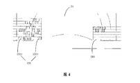
- FIG. 4 is a partially enlarged schematic diagram of FIG. 3.
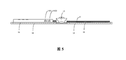
- FIG. 5 is a schematic rear view of the handwriting input device shown in FIG. 1.
- FIG. 6 is a schematic diagram of the handwriting input device of FIG. 1 in a page turning state.
- FIG. 7 is a partially enlarged schematic diagram of FIG. 6.
- FIG. 8 is a flowchart of a page positioning method according to an embodiment of the present application.
- FIG. 1 is a schematic diagram of a handwriting input device 100 according to an embodiment of the present application.
- the handwriting input device 100 is used to communicate with an external device 200.
- the handwriting input device 100 includes a handwriting pad 1, a stylus pen 2, and a writing pad 3.
- the tablet 1 has a surface F1.
- the writing pad 3 is disposed on a surface F1 of the tablet 1.
- the writing pad 3 includes a plurality of sheets 31 arranged in a stack. One side of the plurality of paper sheets 31 is fixed on the surface F1 of the tablet 1, and the plurality of paper sheets 31 can be turned around the side.
- the stylus pen 2 is used for writing on a paper 31 of a writing pad 3 placed on the writing board 1.
- the handwriting tablet 1 is used for sensing a touch track of the stylus pen 2 when writing on a paper 31 of a writing pad 3 placed on the handwriting board 1 and identifying corresponding writing content according to the touch track. Data, and sending the written content data to the external device 200 so that the external device 200 displays the corresponding written content.
- the stylus pen 2 is a stylus pen with ink such as ink.
- the tablet 1 includes a processor 11 and a sensing module 13.
- the sensing module 13 is electrically connected to the processor 11.
- the sensor module 13 is disposed at a position that each paper 31 passes through, and a paper identification code 131 is provided at a position corresponding to the sensor module 13 of each paper 31 (as shown in FIG. 3).
- the sensor module 13 senses the paper identification code 131 of the corresponding paper 31 and sends the sensing data to the processor 11, and the processor 11 determines the currently exposed paper 31 through the paper identification code 131.
- Page number The currently exposed paper 31 refers to the paper 31 that is currently facing the user and is not covered by other paper 31.
- the currently exposed paper 31 may be one sheet or two sheets. If the last turned paper 31 is the first or last page of the writing book 3, the page number of the currently exposed paper 31 is one; otherwise, the page number of the currently exposed paper 31 is two, including the last turned paper A page number of a and a page number of a sheet of paper adjacent to the last page turned.
- the paper identification code 131 is disposed in a thickness direction of each sheet of paper 31.
- the sensing module 13 senses the turning of each paper 31 and generates a sensing signal.
- the processor 11 receives the sensing signal and determines the last turned paper 31 according to the sensing signal, and determines the page number of the currently exposed paper 31 according to the paper identification code 131 of the last turned paper 3 and its turning direction.
- the sensing module 13 senses the flipping of each paper 31 and generates a sensing signal. If the sensing module 13 does not generate a new signal within a preset period of time, In the case of the sensing signal, the processor 11 determines that the paper 31 corresponding to the currently received sensing signal is the last flipped paper 31.
- the sensing module 13 sequentially scans the paper identification code 131 of each flipped paper 31 and sequentially generates a sensing signal.
- the processor 11 sequentially receives the above-mentioned induction signals, and processes the first received induction signal and the last received induction signal among the above-mentioned induction signals, so as to identify the first and last flips in the at least one flipped paper 31.
- the number of pages of the paper 31, and the page number of the currently exposed paper 31 is determined according to the number of pages of the last turned paper 31 and its turning direction when the at least one paper 31 is turned over.
- the sensing module 13 when at least one sheet of paper 31 is flipped, sequentially scans the paper identification code 131 of each of the at least one sheet of paper 31 and sequentially generates a sensing signal.
- the processor 11 sequentially receives the sensing signals generated when the sensing module 13 scans the paper identification code 131 of each paper 31, and sequentially processes the sensing signals to identify the number of pages of each flipped paper 31, and When the turning of the paper 31 ends, the last turned paper 31 is determined, and the page number of the currently exposed paper 31 is determined according to the number of pages of the last turned paper and its turning direction.
- the page number of the last turned paper 31 is 3, and the page numbers of the currently exposed paper 31 may be 4 and 5, or 6 and 7. If the turning direction of the last turned paper 31 is toward Turn the page backward to determine the page numbers of the currently exposed paper 31 as 4 and 5. If the turning direction of the last turned paper 31 is to turn pages forward, it is determined that the page numbers of the currently exposed paper 31 are 6 and 7.
- the tablet 1 further includes a memory 14 and a communication unit 15.
- An electronic document is stored in the memory 14.
- the communication unit 15 is electrically connected to the processor 11.
- the processor 11 When determining the page number of the currently exposed paper 31, the processor 11 also determines whether an electronic document corresponding to the page number of the currently exposed paper 31 is stored in the memory 14. If not, create a new blank electronic document, and if so, retrieve the electronic document corresponding to the page number from the memory 14 and send the blank document or the electronic document to the external device 200 through the communication unit 15 For the external device 200 to perform a corresponding display, such as displaying a newly created blank page or displaying a corresponding electronic document.
- a binder 12 is disposed on the surface F1 of the tablet 1, and the writing pad 3 has a binding edge 33.
- the binding edge 33 of the writing pad 3 is bound to the tablet 1 through the binder 12, and the paper 31 of the writing pad 3 can be flipped around the axis of the binder 12 to move to the previous or next page.
- the paper 31 has a corner region 311 adjacent to the binder 12.
- the sensing module 13 is disposed on the surface F1 of the tablet 1 and is adjacent to the end of the ring binder 12 and the corner area 311.
- the paper identification code 131 of each paper 31 is set at its corresponding position. Within the corner region 311.
- the sensor module 13 is disposed on a side of the surface of the tablet 1 perpendicular to the binding edge 33 and at one end of the binder 12, and the paper identification code 131 of the paper 31 is provided. Within the detection range of the sensing module 13. Therefore, during the entire turning process of the paper 31, the paper identification code 131 of the paper 31 passes through the sensor module 13. Therefore, during the turning process of the plurality of papers 31, the sensing module 13 can sense and generate a sensing signal.
- the tablet 1 includes two cover portions 14 and two sets of sensor arrays 16.
- the two sets of sensor arrays 16 are respectively disposed on opposite surfaces of the two cover parts 14. Several sheets of paper 31 are spread out, one part is placed on one of the sensor arrays 16, and the other part is placed on the other sensor array 16.
- the two sets of sensor arrays 16 are used to sense the touch trajectory when writing with the stylus pen 2 on the paper 31 located on one of the sensor arrays 16, and obtain corresponding writing content data according to the touch trajectories, and The writing content data is transmitted to the external device 200 so that the external device 200 displays the corresponding writing content.
- the processor 11 After determining the page number of the paper 31 presented in front of the user, the processor 11 is based on the writing position of the stylus pen 2 on the sensor array 16 of the tablet 1 and the paper currently presented in front of the user. 31 page number to determine the page number of the current writing paper.
- Each cover portion 14 has a writing area 141 and an edge area 143.
- the edge region 143 is “concave” and is disposed around the writing region 141.
- the sensor array 16 is disposed in the writing area 141.
- the processor 11 is disposed on the edge region 143 and is electrically connected to the sensor array 16.
- the edge area 143 is provided with a charging data interface 1431 and a video interface 1433.
- the charging data interface 1431 and the video interface 1433 are electrically connected to the processor 11.
- the charging data interface 1431 is used for a charging connection or a data transmission connection.
- the video interface 1433 is used for video data transmission connection.
- the tablet 1 includes a connecting portion 17.
- the connecting portion 17 is located between the two cover portions 14 and connects the two cover portions 14 like a spine, so that the tablet 1 forms a book-shaped handwriting input device 100.
- the sensing module 13 is disposed at one end of the connecting portion 17 and is adjacent to the binder 12.
- the length and width dimensions of the two cover portions 14 are equal.
- the connecting portion 17 is located between the two cover portions 14. That is, the connecting portion 17 is located on the axis of symmetry of the two cover portions 14. Both ends of the connecting portion 17 extend to a position flush with both ends of the cover portion 14.
- the ring binder 12 is disposed on the connecting portion 17, and the extending direction of the ring binder 12 is consistent with the length direction of the connecting portion 17; and the ring binder 12 is in the length direction
- the upper part is shorter than the connecting part 17, so that the connecting part 17 forms a receiving space at a position of the end of the binder 12.
- the sensing module 13 is disposed in the receiving space and is adjacent to an end of the binder 12.
- the sensing module 13 and the paper identification code 131 may also be disposed at other suitable positions, and are not limited to the positions listed above, as long as the writing pad can be positioned 3's current page.
- the paper identification code 131 is formed by a plurality of identification points 1311 arranged at intervals.
- Each paper identification code 131 includes a plurality of spaced apart identification points 1311, and the number of identification points 1311, the width of the identification points 1311, and the interval between the identification points 1311 included in each paper identification code 131 are different and unique. And corresponds to the number of pages of the paper 31 one-to-one.
- the paper identification code 131 on each paper 31 is a unique identification code, and the identification code corresponds to the number of pages of the paper 31 one by one, and combined with the turning direction of the last flipped paper 31, therefore, the currently exposed
- the page number of the paper 31 can be accurately positioned, and the number of pages to be turned cannot be discriminated because a plurality of papers 31 are turned at one time.
- the recognition point 1311 has a characteristic of reflecting the received light back
- the sensing module 13 receives light data reflected by the plurality of recognition points 1311 and generates a sensing signal.
- the processor 11 identifies the paper identification code 131 according to the sensing signal, and retrieves a correspondence table between a preset paper identification code and the number of paper pages from a database stored in the memory 14 to determine the relationship between the paper identification code and the number of paper pages.
- the page number corresponding to the paper identification code 131 is described, so that the page number of the currently exposed paper 31 can be determined in combination with the page number of the last turned paper 31 and its turning direction.
- the identification point 1311 is a fluorescent printing ink point. It can be understood that, in other embodiments, the identification point 1311 is an ink point made of other materials and having a light reflection function.
- the sensing module 13 has a first sensing area 133 and a second sensing area 134.
- the first sensing area 133 and the second sensing area 134 are located at two positions on the tablet 1 that the paper 31 passes when the paper 31 is turned.
- the processor 11 receives the first sensing area 133 and the first sensing area 133. After determining the sensing signals generated by the two sensing areas 134, when it is determined that the sensing signals of the first sensing area 133 and the second sensing area 134 are generated within a preset time, according to receiving the first sensing area 133 and the second sensing area 134 The sequence of the sensing signals of the units determines the turning direction of the paper 31 of the writing pad 3.
- the processor 11 when the processor 11 first receives the sensing signal from the first sensing area 133 and then receives the sensing signal from the second sensing area 134, it determines that the turning direction of the paper 31 of the writing pad 3 is toward Back page. In other words, the page turning backward refers to turning the paper 31 from a position above the cover portion 14 on the left toward a position above the cover portion 14 on the right.
- the processor 11 first receives the sensing signal from the second sensing area 134 and then receives the sensing signal from the first sensing area 133, it determines that the turning direction of the paper 31 of the writing pad 3 is to page forward. . In other words, turning the page forward refers to turning the paper 31 from a position above the cover portion 14 on the right toward a position above the cover portion 14 on the left.
- first sensing area 133 and the second sensing area 134 are arranged side by side.
- the processor 11 determines whether to receive the sensing signals generated by the first sensing area 133 and the second sensing area 134 after receiving the sensing signals generated by the first sensing area 133 and the second sensing area 134. Whether the interval is within a preset time (for example, within 2 seconds). Only when it is determined that the interval for receiving the sensing signals generated by the first sensing area 133 and the second sensing area 134 is within the preset time, the first sensing area 133 is received. The sequence of the sensing signals from the second sensing area 134 determines the turning direction of the paper 31 of the writing pad 3. Therefore, by determining that the sensing signals generated by the first sensing area 133 and the second sensing area 134 are received sequentially within a preset time, misjudgment is avoided.
- a preset time for example, within 2 seconds
- the processor 11 when the processor 11 first receives the sensing signal from the first sensing area 133 and then receives the sensing signal from the second sensing area 134, it determines that the turning direction of the paper 31 of the writing pad 3 is page turning backward. (I.e. scroll to the next page). When the processor 11 first receives the sensing signal from the second sensing area 134 and then receives the sensing signal from the first sensing area 133, it determines that the turning direction of the paper 31 of the writing pad 3 is page turning forward (that is, turning to the previous page) page).
- the paper 31 moves from the position close to the surface F1 of the tablet 1 toward the surface F1 far from the tablet 1 and will first pass through the first A sensing area 133 passes through the second sensing area 134.
- the paper 31 moves from the position F1 away from the surface F1 of the tablet 1 toward the surface F1 close to the tablet 1 and will pass first.
- the second sensing area 134 passes through the first sensing area 133.
- the processor 11 when the processor 11 first receives the sensing signal from the first sensing area 133 and then receives the sensing signal from the second sensing area 134, it determines that the turning direction of the paper 31 of the writing pad 3 is page turning backward. When the processor 11 first receives the sensing signal from the second sensing area 134 and then receives the sensing signal from the first sensing area 133, it determines that the turning direction of the paper 31 of the writing pad 3 is to turn pages forward.
- the sensing module 13 is an infrared light sensor
- the first sensing area 133 and the second sensing area 134 are two side-by-side partitions of the infrared light sensor. It can be understood that, in other embodiments, the first sensing area 133 and the second sensing area 134 are independent infrared light sensors arranged side by side.
- the sensing module 13 is a color recognition sensor, and the paper identification code 131 is a color identification point. It can be understood that the color values of the color identification points of each paper 31 of the writing book 3 are different.
- the memory 14 stores a correspondence between a color value and a number of sheets of paper.
- the sensing module 13 senses a paper identification code 131 of the paper 31 and generates a sensing signal including a paper color value.
- the processor 11 receives the sensing signal and determines the number of pages of the paper 31 according to a paper color value of the sensing signal.
- the first sensing area 133 and the second sensing area 134 are two side-by-side partitions of the same color recognition sensor. It can be understood that, in other embodiments, the first sensing area 133 and the second sensing area 134 are independent color recognition sensors disposed side by side.
- the sensing module 13 includes a direction sensing unit and a page number recognition unit.
- the direction sensing unit may be an infrared light sensor or a color recognition sensor.
- the direction sensing unit is used to sense the turning direction of the paper 31.
- the page number identification unit may be a magnetic induction sensor.
- the paper identification code 131 is a combination of magnetic powder identification points. It can be understood that the width of the magnetic powder identification dots and the interval width between the identification dots of each paper 31 of the writing book 3 are different.
- the page number recognition unit is configured to identify a paper identification code 131 of the flipped paper 31.
- the memory 14 stores a correspondence between a preset paper identification code and the number of paper pages.
- the sensing module 13 senses the paper identification code 131 of the paper 31 and generates a sensing signal.
- the processor 11 receives the sensing signal and determines the number of pages corresponding to the paper identification code 131 according to the sensing signal, so that the number of pages of the currently exposed paper 31 and the turning of the currently exposed paper 31 can be combined
- the direction determines the page number of the currently exposed paper 31.
- the sensing module 13 is a sensing module disposed adjacent to the first side or the second side.
- the recognition area of the sensing module 13 is large enough, that is, the first side or the second side can be
- the paper identification codes 131 of all the papers 31 on the side are all recognized. Therefore, as long as the paper identification codes 131 of all the papers on the first side or the second side are identified, the page number of the uppermost paper 31 on the side can be known. That is, when the paper 31 is flipped, the processor 11 senses the paper identification code 131 of the currently exposed paper 31 through the sensing module 13 to determine the page number of the currently exposed paper 31.
- the sensor module 13 is a sensor module 13 adjacent to the first side and the second side at the same time.
- the sensor module 13 can identify the page turning direction, but all paper
- the paper identification code 131 of 31 can be the same, that is, the number of pages of the paper 31 and the page turning direction are identified by the sensing module 13 to determine the page number of the paper 31 that is finally located at the top. That is, when the paper 31 is turned, the processor 11 senses the paper identification code 131 of the turned paper 31 through the sensing module 13 to determine the number of pages of the turned paper 31, and then according to the The number of pages determines the page number of the paper 31 currently exposed.
- the processor 11 passes the sensing signal generated by the sensing module 13 determines the page number of the currently exposed paper 31, and the page positioning is more accurate.
- the processor 11 may be a central processing unit, a single-chip microcomputer, a digital signal processor, a microcontroller, or the like.
- the memory 14 may be a solid-state memory, a memory card, or the like.
- the communication unit 15 may be a wireless module such as a Bluetooth module, a WIFI module, or a GPRS communication module, or may be a wired interface unit such as a USB interface or a FireWire interface.
- first sensing area 133 and the second sensing area 134 in this application do not specifically refer to a certain sensing module, but are named after the first and second in order to facilitate the distinction.
- the external device 200 may be a device such as a mobile phone or a tablet computer, and an application software (APP) supporting the handwriting input device 100 is installed.
- APP application software
- FIG. 8 is a flowchart of a page positioning method according to an embodiment of the present application.
- the page positioning method is used in the aforementioned handwriting input device 100.
- the handwriting input device 100 includes a tablet 1 and a writing pad 3 placed on the surface of the writing pad 1.
- the writing pad 3 includes a plurality of sheets 31.
- the board 1 includes a sensor module 13.
- the sensor module 13 is disposed at a position that each paper 31 passes through.
- Each paper 31 is provided with a paper identification code 131 at a position corresponding to the sensor module 13.
- the sensing module 13 senses the paper identification code 131 of the corresponding paper 31 and generates a sensing signal.
- the page positioning method includes the following steps.
- Step S810 When the paper 31 is turned, the sensing module 13 senses the paper identification code 131 of the corresponding paper 31 and generates a sensing signal.
- the sensing module 13 senses the paper identification code 131 of the currently exposed paper 31 and generates a sensing signal.
- the sensing module 13 senses the paper identification code 131 of the turned paper 31 and generates a sensing signal.
- Step S820 Determine the page number of the currently exposed paper 31 according to the sensing signal.
- the sensing The module 13 recognizes the paper identification codes 131 of all the papers on the first side or the second side, and can know the page numbers of the uppermost paper 31 on the side.
- the sensing module 13 senses the paper identification codes 131 of all papers on the first side or the second side, and generates a sensing signal.
- the processor 11 determines the page number of the currently exposed paper 31 according to the sensing signal.
- the sensing module 13 is a sensing module 13 adjacent to the first side and the second side at the same time.
- the sensing module 13 can identify a page turning direction, but all
- the paper identification code 131 of the paper 31 can be the same, that is, the number of pages of the paper 31 and the page turning direction are recognized by the sensing module 13 to determine the page number of the paper 31 that is finally located at the top. That is, when the paper 31 is turned, the processor 11 senses the paper identification code 131 of the turned paper 31 through the sensing module 13 to determine the number of pages of the turned paper 31, and then according to the The number of pages determines the page number of the paper 31 currently exposed.
- the last turned paper 31 is determined according to the sensing signal, and the page number of the currently exposed paper 31 is determined according to the paper identification code 131 of the last turned paper 31 and its turning direction. .
- the sensing areas corresponding to the sensing module 13 are a first sensing area 133 and a second sensing area 134.
- the determination of the turning direction of the last turned paper 31 includes:
- the turning direction of the paper 31 of the writing pad 3 is determined according to the sequence of receiving the sensing signals of the first sensing area 133 and the second sensing area 134.
- an interval of receiving the sensing signals generated by the first sensing area 133 and the second sensing area 134 is within a preset time; if so, according to receiving the first sensing area 133 and the second sensing area
- the sequence of the sensing signals of the sensing area 134 determines the turning direction of the paper 31 of the writing pad 3.
- the sensing signal of the first sensing area 133 is received first, and then the sensing signal of the second sensing area 134 is received, it is determined that the turning direction of the paper 31 of the writing book 3 is page turning backward; And when the sensing signal of the second sensing area 134 is received first, and then the sensing signal of the first sensing area 133 is received, it is determined that the turning direction of the paper 31 of the writing pad 3 is to turn pages forward.
- the sensing module 13 sequentially scans a paper identification code 131 of each of the at least one sheet of paper 31 and sequentially generates a sensing signal; and sequentially receives the sensing signals, And processing the first received sensing signal and the last received sensing signal among the above-mentioned sensing signals to identify the number of pages of the first and last flipped paper 31 among the at least one flipped paper 31, and in the When the turning of at least one sheet of paper 31 ends, the page number of the currently exposed sheet 31 is determined according to the number of pages of the last sheet of paper 31 and its turning direction.
- a sensing signal generated when the sensing module 13 scans the paper identification code 131 of each paper 31 is sequentially received, and the sensing signals are sequentially processed to identify the number of pages of each flipped paper 31
- the last turned paper 31 is determined, and the page number of the currently exposed paper 31 is determined according to the number of pages of the last turned paper 31 and its turning direction.
- the page positioning method further includes:
- Step S830 After determining the page number of the currently exposed paper 31, a blank electronic document or electronic document corresponding to the page number is retrieved and sent to the external device 200 for display.
- the page positioning method further includes:
- Step S840 When the stylus pen 1 senses that the stylus pen 2 enters a preset operation in its writing area 141, it controls the stylus pen 1 to enter the history review mode, and displays a selection of writing page numbers to output display contents to the outside.
- the page positioning method further includes:
- Step S850 The writing area 141 of the tablet 1 senses the page number entered in the writing page number selection item and controls the tablet 1 to enter the historical review mode, and can perform content annotation.
- Step S860 The tablet 1 calls up the page storage content corresponding to the page number and pushes the content to the external device 200 for display.
- Step S870 Annotate the area block corresponding to the writing area 141 on the paper 31 of the tablet 1 by the stylus 2 and keep the original content unchanged, and the content of the annotation is also pushed to the external device 200 display.
- the page positioning method further includes:
- Step S880 In response to the page turning operation performed in the writing area 141, a prompt is output on the external device 200 to indicate whether the annotation content is merged, and the external device 200 is controlled to perform a corresponding page turning operation.
- the handwriting input device and page positioning method of the present application can accurately identify the page number of the currently exposed paper even if multiple sheets are turned at one time, the page number is accurately identified, and the response is more timely and convenient.
- the page positioning method provided in this application can be implemented in hardware or firmware, or can be used as software or computer code that can be stored in a computer-readable storage medium such as a CD, ROM, RAM, floppy disk, hard disk, or magneto-optical disk, or can Computer code that is originally stored on a remote recording medium or a non-transitory machine-readable medium, downloaded over a network, and stored in a local recording medium, so that the methods described herein can utilize a general-purpose computer or special processor or in a device such as ASIC or FPGA Programmable or dedicated hardware such as software is presented as software stored on a recording medium.
- a computer-readable storage medium such as a CD, ROM, RAM, floppy disk, hard disk, or magneto-optical disk
- a computer, processor, microprocessor, controller, or programmable hardware includes a memory component, such as RAM, ROM, flash memory, etc., which is stored when the computer, processor, or hardware implements the processing methods described herein.
- the memory component can store or receive the software or computer code.
- a general-purpose computer accesses code for implementing the processing shown here, execution of the code converts the general-purpose computer into a special-purpose computer for performing the processing shown here.
- the computer-readable storage medium may be a solid-state memory, a memory card, an optical disc, or the like.
- the computer-readable storage medium may also be the foregoing memory, that is, the memory stores program instructions for the processor to call and execute the page positioning method shown in FIG. 8.
Landscapes
- Engineering & Computer Science (AREA)
- Physics & Mathematics (AREA)
- General Engineering & Computer Science (AREA)
- Theoretical Computer Science (AREA)
- Electromagnetism (AREA)
- Human Computer Interaction (AREA)
- General Physics & Mathematics (AREA)
- Multimedia (AREA)
- Signal Processing (AREA)
- User Interface Of Digital Computer (AREA)
Abstract
本申请公开手写输入装置,包括手写板和写字本,写字本放置于手写板的表面上,写字本包括多个层叠设置的纸张,手写板包括处理器和与处理器电性连接的感应模组,感应模组设置在每个纸张翻动过程中均会经过的位置上,每一纸张对应所述感应模组的位置上设置有纸张识别码,当纸张翻动时,所述处理器通过所述感应模组感应相应纸张的纸张识别码而确定当前外露的纸张的页码。本申请还公开页面定位方法。本申请可以响应纸张的翻动而自动识别当前外露的纸张的页码,页面定位准确。
Description
本申请涉及一种输入装置,尤其涉及一种手写输入装置及其页面定位方法。
目前,随着智能手写输入装置的不断发展及其记录的便捷性,智能手写输入装置已经广泛应用在会议记录等各种需要记录信息的场合中。现在使用较广泛的智能手写输入装置为手写板的上方铺设纸张,人们可以通过手写笔在纸张上进行实体字迹的书写,同时手写笔与手写板将侦测书写的内容,并控制将书写内容显示在其他设备中。在一些使用场景中,放在手写板上方的纸张往往有多张,用户往往需要在写完一张时,翻动到下一张,或者需要返回上一张,增加补充记录内容。现有技术中,当用户一次翻动多张纸张时,系统无法识别翻页纸张的页码,由此造成书写内容与系统存储记录内容出现错乱或重叠或漏记录等现象,操作不便。
发明内容
本申请实施例公开一种手写输入装置及其页面定位方法,能够在用户进行多张纸张翻动时,自动响应用户的纸张翻动动作而识别并定位当前外露的纸张的页码,以解决上述问题。
本申请实施例公开一种手写输入装置,包括手写板和写字本,所述写字本放置于所述手写板的表面上,所述写字本包括多个层叠设置的纸张,所述手写板包括处理器和与所述处理器电性连接的感应模组,所述感应模组设置在每个所述纸张翻动过程中均会经过的位置上,每一纸张对应所述感应模组的位置上设置有纸张识别码,当纸张翻动时,所述处理器通过所述感应模组感应相应纸张的纸张识别码而确定当前外露的纸张的页码。
本申请实施例还公开一种页面定位方法,应用于一手写输入装置中,所述手写输入装置包括手写板以及放置于手写板表面上的写字本,所述写字本包括 多个纸张,所述手写板包括感应模组,所述感应模组设置在每个所述纸张翻动过程中均会经过的位置上,每一纸张对应所述感应模组的位置上设置有纸张识别码,所述页面定位方法包括:当纸张翻动时,所述感应模组感应相应纸张的纸张识别码并产生感应信号;根据所述感应信号确定当前外露的纸张的页码。
本申请的手写输入装置及其页面定位方法,通过设置在所述多个纸张翻动过程中均会经过的位置上的感应模组,当纸张翻动时,所述处理器通过所述感应模组感应相应纸张的纸张识别码而确定当前外露的纸张的页码,即使一次翻动多张纸张,同样能够准确的识别当前外露的纸张的页码,页码识别准确,响应更及时也更加便捷。
为了更清楚地说明本申请实施例中的技术方案,下面将对实施例中所需要使用的附图作简单地介绍,显而易见地,下面描述中的附图仅仅是本申请的一些实施例,对于本领域普通技术人员来讲,在不付出创造性劳动的前提下,还可以根据这些附图获得其他的附图。
图1为本申请一实施例中的手写输入装置在俯视状态的示意图。
图2为本申请一实施例中的手写板的硬件结构框图。
图3为图1所示手写输入装置的主视图。
图4为图3中的局部放大示意图。
图5为图1所示手写输入装置的后视示意图。
图6为图1所述手写输入装置在翻页状态的示意图。
图7为图6的局部放大示意图。
图8为本申请一实施例中的页面定位方法的流程图。
下面将结合本申请实施例中的附图,对本申请实施例中的技术方案进行清楚、完整地描述,显然,所描述的实施例仅是本申请一部分实施例,而不是全 部的实施例。基于本申请中的实施例,本领域普通技术人员在没有做出创造性劳动前提下所获得的所有其他实施例,都属于本申请保护的范围。
本申请的说明书和权利要求书中的术语“包括”以及它们任何变形,意图在于覆盖不排他的包含。例如包含了一系列步骤或单元的过程、方法、系统、产品或设备没有限定于已列出的步骤或单元,而是可选地还包括没有列出的步骤或单元,或可选地还包括对于这些过程、方法、产品或设备固有的其它步骤或单元。
请参阅图1,图1为本申请一实施例中的手写输入装置100的示意图。所述手写输入装置100用于与一外部设备200通信连接。具体地,所述手写输入装置100包括手写板1、手写笔2以及写字本3。所述手写板1具有表面F1。所述写字本3设置于所述手写板1的表面F1上。所述写字本3包括多个层叠设置的纸张31。所述多个纸张31的一边被固定在所述手写板1的表面F1上,且所述多个纸张31能够绕该边翻动。所述手写笔2用于在放置于所述手写板1上的写字本3的纸张31上进行书写。所述手写板1用于感测所述手写笔2在放置于所述手写板1上的写字本3的纸张31上进行书写时的触控轨迹,并根据触控轨迹识别出对应的书写内容数据,及将该书写内容数据发送给外部设备200以使所述外部设备200显示相应的书写内容。其中,所述手写笔2为具有油墨等墨水的触控笔,手写笔2在放置于手写板1上的写字本3的所述纸张31上进行书写时,在纸张31上形成实际的书写字迹的同时,在手写板1上形成与该实际笔迹相对应的电子笔迹。
请一并参阅图2,图2为所述手写板1的结构框图。所述手写板1包括处理器11和感应模组13。感应模组13与处理器11电性连接。感应模组13设置在每个纸张31翻动过程中均会经过的位置上,每一纸张31对应感应模组13的位置上设置有一纸张识别码131(如图3所示)。当纸张31翻动时,所述感应模组13感应相应纸张31的纸张识别码131并将感测数据发送给处理器11,所述处理器11通过所述纸张识别码131确定当前外露的纸张31的页码。其中,当前外露的纸张31是指当前朝向用户的未被其他纸张31覆盖的纸张31。可以理解,当前外露的纸张31可为一张纸或两张纸。若最后翻动的纸张31是写字本3的第一页或最后一页,则该当前外露的纸张31的页码为一个;否则,该当前外露的纸张31的页码 为两个,包括最后翻动的纸张的一个页码及与该最后翻动的纸张相邻的一张纸的一个页码。
从而,本申请中,无论一张纸张31翻动,还是多张纸张31同时翻动,都可以准确地确定当前外露的纸张31的页码,页面定位更准确。
具体地,在一实施例中,所述纸张识别码131设置于每页纸张31的厚度方向上。
具体地,在一实施例中,当纸张31翻动时,所述感应模组13感应每个纸张31的翻动并产生感应信号。所述处理器11接收所述感应信号并根据所述感应信号确定最后翻动的纸张31,且根据最后翻动的纸张3的纸张识别码131及其翻动方向确定当前外露的纸张31的页码。
例如,当以从左翻动到右的第一方向翻动n张纸张31时,感应模组13感应每个纸张31的翻动并产生感应信号,若预设时间段内,感应模组13没有产生新的感应信号时,处理器11确定当前最后接收到的感应信号对应的纸张31即为最后翻动的纸张31。
具体地,在一实施例中,当至少一张纸张31翻动时,所述感应模组13依次扫描每一翻动的纸张31的纸张识别码131并依次产生感应信号。所述处理器11依次接收上述感应信号,并处理上述感应信号中的第一接收的感应信号和最后接收的感应信号,以识别所述至少一张翻动的纸张31中的最先翻动和最后翻动的纸张31的页数,且在所述至少一张纸张31翻动结束时根据最后翻动的纸张31的页数及其翻动方向确定当前外露的纸张31的页码。
可理解,在另一实施例中,当至少一张纸张31翻动时,所述感应模组13依次扫描所述至少一张纸张31中每一纸张31的纸张识别码131并依次产生感应信号。所述处理器11依次接收所述感应模组13扫描每一纸张31的纸张识别码131时产生的感应信号,并依次处理上述感应信号,以识别所述每一翻动纸张31的页数,并在该纸张31翻动结束时确定最后翻动的纸张31,且根据所述最后翻动的纸张的页数及其翻动方向确定当前外露的纸张31的页码。
举例说明,在一实施例中,最后翻动的纸张31的页数是3,则当前外露的纸张31的页码可能是4和5,或者6和7,如果最后翻动的纸张31的翻动方向是向后翻页,则确定当前外露的纸张31的页码为4和5。如果最后翻动 的纸张31的翻动方向是向前翻页,则确定当前外露的纸张31的页码为6和7。
在一实施例中,所述手写板1还包括存储器14和通信单元15。所述存储器14中存储有电子文档。所述通信单元15与所述处理器11电性连接。所述处理器11在确定好所述当前外露的纸张31的页码时,还判断所述存储器14中是否存储与所述当前外露的纸张31的页码对应的电子文档。如果没有,则新建空白电子文档,如果有,则从所述存储器14中调取该页码对应的电子文档,并将所述空白文档或者所述电子文档通过所述通信单元15发送给外部设备200,以供所述外部设备200执行对应的显示,例如,显示新建空白页面或显示对应的电子文档等。
在一实施例中,所述手写板1的表面F1上设置有活页夹12,所述写字本3具有一装订边33。所述写字本3的装订边33通过所述活页夹12装订在所述手写板1上,所述写字本3的纸张31能够绕所述活页夹12的轴线翻转而翻动到上一页或下一页。所述纸张31具有邻近所述活页夹12的边角区域311。所述感应模组13设置在所述手写板1的表面F1上并与所述活页夹12的末端和所述边角区域311相邻,每个纸张31的纸张识别码131设置在其对应的所述边角区域311内。
在一实施例中,所述感应模组13设置于手写板1表面的与所述装订边33垂直的侧边上并位于所述活页夹12的一端,所述纸张31的纸张识别码131设置在所述感应模组13的侦测范围内。从而,所述纸张31在整个翻动过程中,所述纸张31的纸张识别码131均经过所述感应模组13。从而,所述多个纸张31在翻动的过程中,所述感应模组13能够感应并产生感应信号。
在一实施例中,所述手写板1包括两个封面部14和两组感应器阵列16。所述两组感应器阵列16分别设置在所述两个封面部14相对的表面上。若干纸张31呈摊开状,一部分放置与其中一个感应器阵列16上,另一部分放置于另一感应器阵列16上。所述两组感应器阵列16用于感应通过手写笔2在位于其中一个感应器阵列16上的纸张31书写时的触控轨迹,并根据触控轨迹得出对应的书写内容数据,并且所述书写内容数据被发送给外部设备200以使所述外部设备200显示相应的书写内容。其中,当确定呈现在用户面前的纸张31的页码后,所述处理器11根据所述手写笔2在所述手写板1的感应器阵列16上 的书写位置,以及当前呈现在用户面前的纸张31的页码来确定当前书写纸张的页码。
在一实施例中,请一并参考图3,每个封面部14具有书写区域141和边缘区域143。所述边缘区域143呈“凹”状,并围绕所述书写区域141设置。所述感应器阵列16设置在所述书写区域141内。所述处理器11设置在所述边缘区域143上并与所述感应器阵列16电性连接。
在一实施例中,请再次参考图1,所述边缘区域143上设置有充电数据接口1431和视频接口1433。所述充电数据接口1431和视频接口1433均与所述处理器11电性连接。其中,所述充电数据接口1431用于充电连接或者数据传输连接。所述视频接口1433用于视频数据的传输连接。
在一实施例中,所述手写板1包括连接部17。所述连接部17位于所述两个封面部14之间,并像书脊一样连接所述两个封面部14,从而使手写板1形成一呈书状的手写输入装置100。所述感应模组13设置在所述连接部17的一端且邻近所述活页夹12的位置上。
在一实施例中,所述两个封面部14的长宽尺寸都相等。所述连接部17位于所述两个封面部14之间。也就是说,所述连接部17位于所述两个封面部14的对称轴线上。所述连接部17的两端延伸至与所述封面部14的两端相平齐的位置上。
在一实施例中,所述活页夹12设置在所述连接部17上,且所述活页夹12的延伸方向与所述连接部17的长度方向一致;而且,所述活页夹12在长度方向上比所述连接部17短,从而,所述连接部17位于所述活页夹12端部的位置上形成一收容空间。所述感应模组13设置在所述收容空间内并邻近所述活页夹12的端部。
可理解,在其它实施例中,所述感应模组13和所述纸张识别码131还可以设置在其它适合的位置上,并不局限于上述已经列举出的位置,只要能够定位所述写字本3的当前页面即可。
在一实施例中,请一并参考图3和图4,所述纸张识别码131由多个识别点1311间隔排列而成。每一纸张识别码131包括多个间隔开的识别点1311,且每一纸张识别码131所包含的识别点1311数量、识别点1311的宽度以及识 别点1311之间的间隔宽度不同并具有唯一性,且与所述纸张31的页数一一对应。从而,每个纸张31上的纸张识别码131都是唯一的识别码,并且,该识别码与该纸张31的页数一一对应,再结合最后翻动纸张31的翻动方向,因而,当前外露的纸张31的页码能够准确定位,而不会因为一次翻动多张纸张31而无法识别翻页页数。
具体地,所述识别点1311具有将所接收到的光线反射回去的特性,所述感应模组13接收经所述多个识别点1311反射后的光线数据,并产生感应信号。所述处理器11根据所述感应信号识别所述纸张识别码131,并从存储在所述存储器14中的数据库中调出预设纸张识别码与纸张页数的对应关系表,以确定与所述纸张识别码131对应的页数,从而能够结合最后翻动的纸张31的页数及其翻动方向确定所述当前外露的纸张31的页码。
具体地,在该实施例中,所述识别点1311为荧光印刷油墨点。可理解,在其它实施例中,所述识别点1311为采用其它材料制成的具有光反射功能的油墨点。
进一步地,请一并参考图5、图6和图7,所述感应模组13具有第一感应区域133和第二感应区域134。所述第一感应区域133和第二感应区域134位于所述手写板1上的当纸张31翻动时会先后经过的两个位置,所述处理器11在接收所述第一感应区域133和第二感应区域134产生的感应信号后,确定第一感应区域133和第二感应区域134的感应信号为在预设时间内产生时,根据接收到所述第一感应区域133和第二感应区域134单元的感应信号的先后顺序确定所述写字本3的纸张31的翻动方向。
进一步地,所述处理器11在先接收到所述第一感应区域133的感应信号,然后接收到第二感应区域134的感应信号时,确定所述写字本3的纸张31的翻动方向为向后翻页。换句话说,所述向后翻页是指将所述纸张31从位于左侧的封面部14上方的位置朝向位于右侧的封面部14的上方的位置翻动。所述处理器11在先接收到所述第二感应区域134的感应信号,然后接收到第一感应区域133的感应信号时,确定所述写字本3的纸张31的翻动方向为向前翻页。换句话说,所述向前翻页是指将所述纸张31从位于右侧的封面部14上方的位置朝向位于左侧的封面部14的上方的位置翻动。
进一步地,所述第一感应区域133以及所述第二感应区域134并排设置。
其中,在一些实施例中,处理器11为在接收第一感应区域133及第二感应区域134产生的感应信号后,还判断接收第一感应区域133及第二感应区域134产生的感应信号的间隔是否在预设时间(例如2秒内)内,当确定接收第一感应区域133及第二感应区域134产生的感应信号的间隔在预设时间内时,才根据接收到第一感应区域133及第二感应区域134的感应信号的先后顺序确定写字本3的纸张31的翻动方向。从而,通过确定第一感应区域133及第二感应区域134产生的感应信号为在预设时间内先后接收到的,避免误判断。
在一些实施例中,处理器11在先接收到第一感应区域133的感应信号,然后接收到第二感应区域134的感应信号时,确定写字本3的纸张31的翻动方向为向后翻页(即翻动到后一页)。处理器11在先接收到第二感应区域134的感应信号,然后接收到第一感应区域133的感应信号时,确定写字本3的纸张31的翻动方向为向前翻页(即翻动到前一页)。
当纸张31的翻动方向为向后翻页(即翻动到后一页)时,纸张31是从贴近手写板1的表面F1的位置朝着远离手写板1的表面F1运动,将会先经过第一感应区域133,再经过第二感应区域134。而当纸张31的翻动方向为向前翻页(即翻动到前一页)时,纸张31是从远离手写板1的表面F1的位置朝着贴近手写板1的表面F1运动,将会先经过第二感应区域134,再经过第一感应区域133。
从而,如前,处理器11在先接收到第一感应区域133的感应信号,然后接收到第二感应区域134的感应信号时,确定写字本3的纸张31的翻动方向为向后翻页。处理器11在先接收到第二感应区域134的感应信号,然后接收到第一感应区域133的感应信号时,确定写字本3的纸张31的翻动方向为向前翻页。
可理解,本实施例中,所述感应模组13为红外光传感器,所述第一感应区域133和所述第二感应区域134为所述红外光传感器的两个并排设置的分区。可理解,在其它实施例中,所述第一感应区域133和所述第二感应区域134为并排设置的独立红外光传感器。
在另一实施例中,所述感应模组13为颜色识别传感器,所述纸张识别码 131为颜色标识点。可理解,所述写字本3的每一纸张31的颜色标识点的颜色值均不相同。所述存储器14中存储颜色值与纸张页数的对应关系。所述感应模组13感应所述纸张31的纸张识别码131并产生包含纸张颜色值的感应信号。所述处理器11接收所述感应信号并根据所述感应信号的纸张颜色值确定所述纸张31的页数。所述第一感应区域133和所述第二感应区域134为同一颜色识别传感器的两个并排设置的分区。可理解,在其它实施例中,所述第一感应区域133和所述第二感应区域134为并排设置的独立的颜色识别传感器。
在又一实施例中,所述感应模组13包括方向感应单元和页码识别单元。其中,所述方向感应单元可以是红外光传感器或者颜色识别传感器。所述方向感应单元用于感应纸张31的翻动方向。所述页码识别单元可以是磁感应传感器。所述纸张识别码131为磁粉标识点组合。可理解,所述写字本3的每一纸张31的磁粉标识点的宽度和标识点之间的间隔宽度均不相同。所述页码识别单元用于识别所述翻动纸张31的纸张识别码131。所述存储器14中存储预设纸张识别码与纸张页数的对应关系。所述感应模组13感应所述纸张31的纸张识别码131并产生感应信号。所述处理器11接收所述感应信号并根据所述感应信号确定与所述纸张识别码131对应的页数,从而能够结合当前外露的纸张31的页数和所述当前外露的纸张31的翻动方向确定所述当前外露的纸张31的页码。
可理解,在其它实施例中,若干纸张31堆叠形成的写字本被翻开时,具有位于其中一组感应器阵列16上方的第一侧和位于另一组感应器阵列16上方的第二侧,所述感应模组13为邻近所述第一侧或者所述第二侧设置的感应模组,所述感应模组13的识别面积足够大,即可以一次把该第一侧或该第二侧所有纸张31的纸张识别码131全部识别出来,因此,只要识别出该第一侧或该第二侧的所有纸张的纸张识别码131,即可得知该侧最上面的纸张31的页码。即,当纸张31翻动时,所述处理器11通过所述感应模组13感应当前外露的纸张31的纸张识别码131而确定当前外露的纸张31的页码。
可理解,在其它实施例中,所述感应模组13是同时邻近所述第一侧和所述第二侧的感应模组13,所述感应模组13可识别翻页方向,但是所有纸张31的纸张识别码131可以相同,即通过感应模组13来识别每次翻过的纸张31 的页数及翻页方向来确定最终位于最上方的纸张31的页码。即,当纸张31翻动时,所述处理器11通过所述感应模组13感应所翻动的纸张31的纸张识别码131而确定所翻动的纸张31的页数,再根据所翻动的纸张31的页数确定当前外露的纸张31的页码。
本申请中,通过将感应模组13设置在手写板1上的当纸张31翻动过程中经过的位置上,当至少一张纸张31翻动时,则会经过感应模组13,处理器11则通过感应模组13产生的感应信号确定当前外露的纸张31的页码,页面定位更准确。
其中,处理器11可为中央处理器、单片机、数字信号处理器、微控制器等。存储器14可为固态存储器、存储卡等。通信单元15可为蓝牙模组、WIFI模组、GPRS通信模组等无线模组,也可为USB接口、火线接口等有线接口单元。
其中,本申请中的第一感应区域133及第二感应区域134并非特指某一感应模组,而是为了便于区分而以第一、第二进行命名。
其中,外部设备200可为手机、平板电脑等装置,并安装有与手写输入装置100配套的应用软件(APP)。
请参阅图8,为本申请一实施例中的页面定位方法的流程图。页面定位方法用于前述的手写输入装置100中,所述手写输入装置100包括手写板1以及放置于手写板1表面上的写字本3,所述写字本3包括多个纸张31,所述手写板1包括感应模组13,所述感应模组13设置在每个纸张31翻动过程中均会经过的位置上,每一纸张31对应所述感应模组13的位置上设置有纸张识别码131,所述感应模组13感应相应纸张31的纸张识别码131并产生感应信号。所述页面定位方法包括如下步骤。
步骤S810:当纸张31翻动时,所述感应模组13感应相应纸张31的纸张识别码131并产生感应信号。
具体地,在一实施例中,当纸张31翻动时,所述感应模组13感应当前外露的纸张31的纸张识别码131并产生感应信号。
具体地,在另一实施例中,当纸张31翻动时,所述感应模组13感应所翻动的纸张31的纸张识别码131并产生感应信号。
步骤S820:根据所述感应信号确定当前外露的纸张31的页码。
具体地,在一实施例中,当所述感应模组13的识别面积足够大到可以一次把该第一侧或该第二侧所有纸张31的纸张识别码131全部识别出来时,所述感应模组13识别出该第一侧或该第二侧的所有纸张的纸张识别码131,即可得知该侧最上面的纸张31的页码。此时,当纸张31翻动的动作完成后,所述感应模组13感应该第一侧或该第二侧的所有纸张的纸张识别码131,并产生感应信号。所述处理器11根据所述感应信号确定当前外露的纸张31的页码。
具体地,在另一实施例中,所述感应模组13是同时邻近所述第一侧和所述第二侧的感应模组13,所述感应模组13可识别翻页方向,但是所有纸张31的纸张识别码131可以相同,即通过感应模组13来识别每次翻过的纸张31的页数及翻页方向来确定最终位于最上方的纸张31的页码。即,当纸张31翻动时,所述处理器11通过所述感应模组13感应所翻动的纸张31的纸张识别码131而确定所翻动的纸张31的页数,再根据所翻动的纸张31的页数确定当前外露的纸张31的页码。
具体地,在另一实施例中,根据所述感应信号确定最后翻动的纸张31,且根据所述最后翻动的纸张31的纸张识别码131及其翻动方向确定所述当前外露的纸张31的页码。
具体地,在一实施例中,所述感应模组13对应的感应区域为第一感应区域133和第二感应区域134,所述最后翻动的纸张31的翻动方向的确定包括:
根据接收到所述第一感应区域133及第二感应区域134的感应信号的先后顺序确定所述写字本3的纸张31的翻动方向。
进一步具体地,确定接收所述第一感应区域133及第二感应区域134产生的感应信号的间隔是否在在预设时间内;如果是,则根据接收到所述第一感应区域133及第二感应区域134的感应信号的先后顺序确定所述写字本3的纸张31的翻动方向。
进一步具体地,在先接收到所述第一感应区域133的感应信号,然后接收到第二感应区域134的感应信号时,确定所述写字本3的纸张31的翻动方向为向后翻页;以及在先接收到所述第二感应区域134的感应信号,然后接收到第一感应区域133的感应信号时,确定所述写字本3的纸张31的翻动方向为 向前翻页。
进一步具体地,当至少一张纸张31翻动时,所述感应模组13依次扫描所述至少一张纸张31中每一纸张31的纸张识别码131并依次产生感应信号;依次接收上述感应信号,并处理上述感应信号中的第一接收的感应信号和最后接收的感应信号,以识别所述至少一张翻动的纸张31中的最先翻动和最后翻动的纸张31的页数,且在所述至少一张纸张31翻动结束时根据最后翻动的纸张31的页数及其翻动方向确定当前外露的纸张31的页码。
在另一实施例中,依次接收所述感应模组13扫描每一纸张31的纸张识别码131时产生的感应信号,并依次处理上述感应信号,以识别所述每一翻动纸张31的页数,并在该纸张31翻动结束时确定最后翻动的纸张31,且根据最后翻动的纸张31的页数及其翻动方向确定当前外露的纸张31的页码。
进一步地,所述页面定位方法还包括:
步骤S830:在确定当前外露的纸张31的页码后,调取该页码对应的空白电子文档或者电子文档发送至所述外部设备200以供显示。
具体地,在确定当前外露的纸张31的当前页码后,判断所述页码是否与有对应的电子文档存储,如果没有,则新建空白电子文档,如果有,则从手写板1的存储器14中调取该页码对应的电子文档,并将所述空白电子文档或者所述电子文档发送至所述外部设备200以供显示。
进一步地,在一实施例中,所述页面定位方法还包括:
步骤S840:所述手写板1感应所述手写笔2在其书写区域141输入预设操作时,控制所述手写板1进入历史回顾模式,并显示要对外输出显示内容的写字本页码选择项。
进一步地,所述页面定位方法还包括:
步骤S850:所述手写板1的书写区域141感应在所述写字本页码选择项中输入的页码并控制所述手写板1进入历史回顾模式,并可以进行内容批注。
步骤S860:所述手写板1调出对应页码的页面存储内容并推送内容到外部设备200上显示。
步骤S870:通过所述手写笔2在所述手写板1的纸张31上对应所述书写区域141的区域块做批注并保持原有内容不改变,所述批注内容也被推动到外 部设备200上显示。
进一步地,所述页面定位方法还包括:
步骤S880:响应在所述书写区域141执行的翻页操作在所述外部设备200上输出提示批注内容是否合并,且控制所述外部设备200执行相应的翻页操作。
如果需要合并,则将批注内容与该页码对应的电子文档进行合并。
从而,本申请的手写输入装置和页面定位方法,即使一次翻动多张纸张,同样能够准确的识别当前外露的纸张的页码,页码识别准确,响应更及时也更加便捷。
本申请提供的页面定位方法可以在硬件、固件中实施,或者可以作为可以存储在例如CD、ROM、RAM、软盘、硬盘或磁光盘的等计算机可读存储介质中的软件或计算机代码,或者可以作为原始存储在远程记录介质或非瞬时的机器可读介质上、通过网络下载并且存储在本地记录介质中的计算机代码,从而这里描述的方法可以利用通用计算机或特殊处理器或在诸如ASIC或FPGA之类的可编程或专用硬件中以存储在记录介质上的软件来呈现。如本领域能够理解的,计算机、处理器、微处理器、控制器或可编程硬件包括存储器组件,例如,RAM、ROM、闪存等,当计算机、处理器或硬件实施这里描述的处理方法而存取和执行软件或计算机代码时,存储器组件可以存储或接收软件或计算机代码。另外,当通用计算机存取用于实施这里示出的处理的代码时,代码的执行将通用计算机转换为用于执行这里示出的处理的专用计算机。
其中,所述计算机可读存储介质可为固态存储器、存储卡、光碟等。所述计算机可读存储介质也可为前述的存储器,即,所述存储器存储有程序指令而供所述处理器调用后执行如图8所示的页面定位方法。
以上所述是本申请的优选实施例,应当指出,对于本技术领域的普通技术人员来说,在不脱离本申请原理的前提下,还可以做出多个改进和润饰,这些改进和润饰也视为本申请的保护范围。
Claims (20)
- 一种手写输入装置,包括手写板和写字本,所述写字本放置于所述手写板的表面上,所述写字本包括多个层叠设置的纸张,所述手写板包括处理器和与所述处理器电性连接的感应模组,所述感应模组设置在每个所述纸张翻动过程中均会经过的位置上,每一纸张对应所述感应模组的位置上设置有纸张识别码,当纸张翻动时,所述处理器通过所述感应模组感应相应纸张的纸张识别码而确定当前外露的纸张的页码。
- 如权利要求1所述的手写输入装置,其特征在于,所述纸张识别码设置于每页纸张的厚度方向上。
- 如权利要求1所述的手写输入装置,其特征在于,当纸张翻动时,所述处理器通过所述感应模组感应当前外露纸张的纸张识别码而确定当前外露的纸张的页码。
- 如权利要求1所述的手写输入装置,其特征在于,当纸张翻动时,所述处理器通过所述感应模组感应所翻动的纸张的纸张识别码而确定所翻动的纸张的页数,再根据所翻动的纸张的页数确定当前外露的纸张的页码。
- 如权利要求1所述的手写输入装置,其特征在于,当纸张翻动时,所述处理器通过所述感应模组感应所翻动的纸张的纸张识别码确定最后翻动的纸张,且根据所述最后翻动的纸张的纸张识别码及其翻动方向确定所述当前外露的纸张的页码。
- 如权利要求1-5任一项所述的手写输入装置,其特征在于,所述纸张识别码包括多个间隔开的识别点,所述多个纸张各自的纸张识别码不同并具有唯一性,且与所述纸张的页码一一对应。
- 如权利要求1-5任一项所述的手写输入装置,其特征在于,所述手写板的表面上设置有活页夹,所述写字本具有装订边,所述写字本通过所述装订边装订在所述手写板上,所述写字本的纸张绕所述活页夹翻转而翻动到上一页或下一页,所述纸张包括邻近所述活页夹的边角区域,所述感应模组设置在所述手写板的表面上并与所述活页夹的末端和所述边角区域相邻,每个纸张的纸张识别码设置在对应的所述边角区域。
- 如权利要求7所述的手写输入装置,其特征在于,所述感应模组设置于所述手写板表面与所述装订边垂直的侧边上并位于所述活页夹的一端,所述纸张的边角区域的纸张识别码设置在所述感应模组的侦测范围内。
- 如权利要求7所述的手写输入装置,其特征在于,所述手写板包括两个封面部和两个感应器阵列,所述两个感应器阵列分别设置在所述两个封面部相对的表面上,所述感应器阵列用于感应在位于所述手写板表面上的所述纸张书写时的书写笔迹。
- 如权利要求9所述的手写输入装置,其特征在于,所述手写板包括连接部,所述连接部连接在所述两个封面部之间,所述感应模组设置在所述连接部邻近所述活页夹的位置上。
- 如权利要求5所述的手写输入装置,其特征在于,所述感应模组对应的感应区域为第一感应区域和第二感应区域,所述第一感应区域和第二感应区域位于所述手写板上的当纸张翻动时会先后经过的两个位置,所述处理器在接收所述第一感应区域和第二感应区域产生的感应信号后,根据接收到所述第一感应区域和第二感应区域单元的感应信号的先后顺序确定所述写字本的纸张的翻动方向。
- 如权利要求1所述的手写输入装置,其特征在于,所述感应模组为红外光感应器或者颜色识别传感器,所述第一感应区域以及所述第二感应区域并 排设置。
- 如权利要求1所述的手写输入装置,其特征在于,所述手写板还包括存储器和通信单元,所述存储器中存储有电子文档,所述手写输入装置通过所述通信单元与外部设备建立通信连接,所述处理器在确定当前外露的纸张的页码后,判断所述页码是否有对应的电子文档存储;如果没有,则新建空白电子文档,如果有,则从所述存储器中调取该页码对应的电子文档,并将所述空白电子文档或者所述电子文档传送至所述外部设备上用于供所述外部设备切换显示。
- 一种页面定位方法,应用于一手写输入装置中,所述手写输入装置包括手写板以及放置于手写板表面上的写字本,所述写字本包括多张可翻动的纸张,所述手写板包括感应模组,所述感应模组设置在每个所述纸张翻动过程中均会经过的位置上,每一纸张对应所述感应模组的位置上设置有纸张识别码,其特征在于,所述页面定位方法包括:当纸张翻动时,所述感应模组感应相应纸张的纸张识别码并产生感应信号;根据所述感应信号确定当前外露的纸张的页码。
- 如权利要求14所述的页面定位方法,其特征在于,“当纸张翻动时,所述感应模组感应相应纸张的纸张识别码并产生感应信号”包括:当纸张翻动时,所述感应模组感应当前外露的纸张的纸张识别码并产生感应信号。
- 如权利要求14所述的页面定位方法,其特征在于,“当纸张翻动时,所述感应模组感应相应纸张的纸张识别码并产生感应信号”包括:当纸张翻动时,所述感应模组感应所翻动的纸张的纸张识别码并产生感应信号,“根据所述感应信号确定当前外露的纸张的页码”包括:根据所述感应信号确定所翻动的纸张的页数,再根据所翻动的纸张的页数确定当前外露的纸张的页码。
- 如权利要求14所述的页面定位方法,其特征在于,“根据所述感应信号确定当前外露的纸张的页码”包括:根据所述感应信号确定最后翻动的纸张,且根据所述最后翻动的纸张的纸张识别码及其翻动方向确定所述当前外露的纸张的页码。
- 如权利要求17所述的页面定位方法,其特征在于,所述感应模组对应的感应区域为第一感应区域和第二感应区域,所述最后翻动的纸张的翻动方向的确定包括:根据接收到所述第一感应区域及第二感应区域的感应信号的先后顺序确定所述写字本的纸张的翻动方向。
- 如权利要求17所述的页面定位方法,其特征在于,“根据所述感应信号确定最后翻动的纸张,且根据所述最后翻动的纸张的纸张识别码及其翻动方向确定所述当前外露的纸张的页码”,包括:依次接收所述感应模组扫描每一翻动的纸张的纸张识别码时产生的感应信号;处理上述感应信号中的第一接收的感应信号和最后接收的感应信号,以识别至少一张翻动的纸张中的最先翻动和最后翻动的纸张的页数;在所述至少一张纸张翻动结束时结合每个纸张的翻动方向以及所述至少一张翻动的纸张中的最先翻动和最后翻动的纸张的页数确定所述当前外露的纸张的页码。
- 如权利要求14所述的页面定位方法,其特征在于,所述手写板包括书写区域,所述页面定位方法还包括:所述手写板的书写区域感应一手写笔在其上输入预设操作时,控制所述手写板进入历史回顾模式,并显示要对外输出显示内容的写字本页码选择项;所述手写板的书写区域感应在所述写字本页码选择项中输入的页码并控制所述手写板进入历史回顾模式;所述手写板调出对应页码的页面存储内容并推送内容到外部设备上显示; 通过手写笔在所述手写板的纸张上对应所述书写区域的区域块做批注并保持原有内容不改变,所述批注内容也被推动到外部设备上显示。
Priority Applications (2)
| Application Number | Priority Date | Filing Date | Title |
|---|---|---|---|
| PCT/CN2018/094850 WO2020006757A1 (zh) | 2018-07-06 | 2018-07-06 | 手写输入装置及其页面定位方法 |
| CN201880093897.3A CN112470111A (zh) | 2018-07-06 | 2018-07-06 | 手写输入装置及其页面定位方法 |
Applications Claiming Priority (1)
| Application Number | Priority Date | Filing Date | Title |
|---|---|---|---|
| PCT/CN2018/094850 WO2020006757A1 (zh) | 2018-07-06 | 2018-07-06 | 手写输入装置及其页面定位方法 |
Publications (1)
| Publication Number | Publication Date |
|---|---|
| WO2020006757A1 true WO2020006757A1 (zh) | 2020-01-09 |
Family
ID=69059904
Family Applications (1)
| Application Number | Title | Priority Date | Filing Date |
|---|---|---|---|
| PCT/CN2018/094850 Ceased WO2020006757A1 (zh) | 2018-07-06 | 2018-07-06 | 手写输入装置及其页面定位方法 |
Country Status (2)
| Country | Link |
|---|---|
| CN (1) | CN112470111A (zh) |
| WO (1) | WO2020006757A1 (zh) |
Citations (5)
| Publication number | Priority date | Publication date | Assignee | Title |
|---|---|---|---|---|
| CN201576359U (zh) * | 2009-12-30 | 2010-09-08 | 成都时代诺亚舟教育软件有限公司 | 能感应翻页方向的电子阅读装置 |
| US20110205170A1 (en) * | 2010-02-24 | 2011-08-25 | Mstar Semiconductor, Inc. | Electronic touch - screen display apparatus and operating method thereof |
| CN104714711A (zh) * | 2013-12-11 | 2015-06-17 | 汉王科技股份有限公司 | 电磁式记事本以及自动换页方法 |
| CN106023671A (zh) * | 2016-05-13 | 2016-10-12 | 广东宝贝儿婴童用品股份有限公司 | 磁感应智能学习机 |
| CN106648278A (zh) * | 2016-12-29 | 2017-05-10 | 鲁伯特(北京)教育科技有限公司 | 自动页码检测装置及检测和扫描方法 |
-
2018
- 2018-07-06 CN CN201880093897.3A patent/CN112470111A/zh active Pending
- 2018-07-06 WO PCT/CN2018/094850 patent/WO2020006757A1/zh not_active Ceased
Patent Citations (5)
| Publication number | Priority date | Publication date | Assignee | Title |
|---|---|---|---|---|
| CN201576359U (zh) * | 2009-12-30 | 2010-09-08 | 成都时代诺亚舟教育软件有限公司 | 能感应翻页方向的电子阅读装置 |
| US20110205170A1 (en) * | 2010-02-24 | 2011-08-25 | Mstar Semiconductor, Inc. | Electronic touch - screen display apparatus and operating method thereof |
| CN104714711A (zh) * | 2013-12-11 | 2015-06-17 | 汉王科技股份有限公司 | 电磁式记事本以及自动换页方法 |
| CN106023671A (zh) * | 2016-05-13 | 2016-10-12 | 广东宝贝儿婴童用品股份有限公司 | 磁感应智能学习机 |
| CN106648278A (zh) * | 2016-12-29 | 2017-05-10 | 鲁伯特(北京)教育科技有限公司 | 自动页码检测装置及检测和扫描方法 |
Also Published As
| Publication number | Publication date |
|---|---|
| CN112470111A (zh) | 2021-03-09 |
Similar Documents
| Publication | Publication Date | Title |
|---|---|---|
| WO2019205552A1 (zh) | 在线文档的评论方法和装置 | |
| KR102727938B1 (ko) | 전자 장치 및 그의 필기 입력을 처리하는 방법 | |
| CN110442264A (zh) | 一种触摸数据处理方法、装置、设备及存储介质 | |
| CN115023683A (zh) | 触控笔、终端及其控制方法和计算机可读存储介质 | |
| WO2019127162A1 (zh) | 手写输入装置及其控制方法 | |
| CN105760084A (zh) | 语音输入的控制方法和装置 | |
| CN111078179B (zh) | 一种听写报读进度的控制方法及电子设备 | |
| KR102213861B1 (ko) | 스케치 검색 시스템, 사용자 장치, 서비스 제공 장치, 그 서비스 방법 및 컴퓨터 프로그램이 기록된 기록매체 | |
| WO2020006757A1 (zh) | 手写输入装置及其页面定位方法 | |
| CN111417026A (zh) | 一种基于书写内容的在线学习方法及装置 | |
| CN111079737B (zh) | 一种文字倾斜矫正方法及电子设备 | |
| CN112639393A (zh) | 纸沓厚度识别装置、纸沓厚度识别方法及手写输入装置 | |
| CN113330446A (zh) | 手写识别方法、电子装置和存储介质 | |
| CN111090343B (zh) | 在点读场景下识别点读内容的方法及装置 | |
| WO2018113638A1 (zh) | 便携式电子终端及待操作对象选定装置与方法 | |
| JP2014085957A (ja) | 表示処理装置、及び表示処理方法 | |
| CN111753604A (zh) | 一种基于学习设备的点读方法及学习设备 | |
| US20220141343A1 (en) | Multipurpose Drawing Tablet | |
| WO2023221517A1 (zh) | 导航控制方法及装置、终端设备、存储介质 | |
| CN111209906B (zh) | 一种基于超声波技术的书写装置及系统 | |
| CN107369130A (zh) | 一种图片处理方法以及终端 | |
| CN111788545A (zh) | 手写输入装置及翻页控制方法 | |
| CN109062524B (zh) | 图书信息的显示方法及其装置和图书信息的显示系统 | |
| US11614836B1 (en) | Apparatus for supporting a reading and method for detecting a user input using the same | |
| TWI672630B (zh) | 電子裝置及音訊錄音控制方法 |
Legal Events
| Date | Code | Title | Description |
|---|---|---|---|
| 121 | Ep: the epo has been informed by wipo that ep was designated in this application |
Ref document number: 18925166 Country of ref document: EP Kind code of ref document: A1 |
|
| NENP | Non-entry into the national phase |
Ref country code: DE |
|
| 122 | Ep: pct application non-entry in european phase |
Ref document number: 18925166 Country of ref document: EP Kind code of ref document: A1 |