WO2020004253A1 - Negative electrode composition for alkaline secondary batteries and negative electrode for alkaline secondary batteries - Google Patents
Negative electrode composition for alkaline secondary batteries and negative electrode for alkaline secondary batteries Download PDFInfo
- Publication number
- WO2020004253A1 WO2020004253A1 PCT/JP2019/024677 JP2019024677W WO2020004253A1 WO 2020004253 A1 WO2020004253 A1 WO 2020004253A1 JP 2019024677 W JP2019024677 W JP 2019024677W WO 2020004253 A1 WO2020004253 A1 WO 2020004253A1
- Authority
- WO
- WIPO (PCT)
- Prior art keywords
- negative electrode
- alkaline secondary
- secondary battery
- particle diameter
- active material
- Prior art date
Links
Images
Classifications
-
- H—ELECTRICITY
- H01—ELECTRIC ELEMENTS
- H01M—PROCESSES OR MEANS, e.g. BATTERIES, FOR THE DIRECT CONVERSION OF CHEMICAL ENERGY INTO ELECTRICAL ENERGY
- H01M4/00—Electrodes
- H01M4/02—Electrodes composed of, or comprising, active material
- H01M4/24—Electrodes for alkaline accumulators
- H01M4/242—Hydrogen storage electrodes
-
- H—ELECTRICITY
- H01—ELECTRIC ELEMENTS
- H01M—PROCESSES OR MEANS, e.g. BATTERIES, FOR THE DIRECT CONVERSION OF CHEMICAL ENERGY INTO ELECTRICAL ENERGY
- H01M10/00—Secondary cells; Manufacture thereof
- H01M10/24—Alkaline accumulators
-
- H—ELECTRICITY
- H01—ELECTRIC ELEMENTS
- H01M—PROCESSES OR MEANS, e.g. BATTERIES, FOR THE DIRECT CONVERSION OF CHEMICAL ENERGY INTO ELECTRICAL ENERGY
- H01M4/00—Electrodes
- H01M4/02—Electrodes composed of, or comprising, active material
- H01M4/24—Electrodes for alkaline accumulators
-
- H—ELECTRICITY
- H01—ELECTRIC ELEMENTS
- H01M—PROCESSES OR MEANS, e.g. BATTERIES, FOR THE DIRECT CONVERSION OF CHEMICAL ENERGY INTO ELECTRICAL ENERGY
- H01M4/00—Electrodes
- H01M4/02—Electrodes composed of, or comprising, active material
- H01M4/36—Selection of substances as active materials, active masses, active liquids
- H01M4/38—Selection of substances as active materials, active masses, active liquids of elements or alloys
- H01M4/383—Hydrogen absorbing alloys
-
- H—ELECTRICITY
- H01—ELECTRIC ELEMENTS
- H01M—PROCESSES OR MEANS, e.g. BATTERIES, FOR THE DIRECT CONVERSION OF CHEMICAL ENERGY INTO ELECTRICAL ENERGY
- H01M4/00—Electrodes
- H01M4/02—Electrodes composed of, or comprising, active material
- H01M4/62—Selection of inactive substances as ingredients for active masses, e.g. binders, fillers
- H01M4/621—Binders
- H01M4/622—Binders being polymers
-
- H—ELECTRICITY
- H01—ELECTRIC ELEMENTS
- H01M—PROCESSES OR MEANS, e.g. BATTERIES, FOR THE DIRECT CONVERSION OF CHEMICAL ENERGY INTO ELECTRICAL ENERGY
- H01M4/00—Electrodes
- H01M4/02—Electrodes composed of, or comprising, active material
- H01M4/62—Selection of inactive substances as ingredients for active masses, e.g. binders, fillers
- H01M4/624—Electric conductive fillers
- H01M4/625—Carbon or graphite
-
- H—ELECTRICITY
- H01—ELECTRIC ELEMENTS
- H01M—PROCESSES OR MEANS, e.g. BATTERIES, FOR THE DIRECT CONVERSION OF CHEMICAL ENERGY INTO ELECTRICAL ENERGY
- H01M4/00—Electrodes
- H01M4/02—Electrodes composed of, or comprising, active material
- H01M4/64—Carriers or collectors
- H01M4/66—Selection of materials
- H01M4/661—Metal or alloys, e.g. alloy coatings
-
- H—ELECTRICITY
- H01—ELECTRIC ELEMENTS
- H01M—PROCESSES OR MEANS, e.g. BATTERIES, FOR THE DIRECT CONVERSION OF CHEMICAL ENERGY INTO ELECTRICAL ENERGY
- H01M4/00—Electrodes
- H01M4/02—Electrodes composed of, or comprising, active material
- H01M2004/021—Physical characteristics, e.g. porosity, surface area
-
- H—ELECTRICITY
- H01—ELECTRIC ELEMENTS
- H01M—PROCESSES OR MEANS, e.g. BATTERIES, FOR THE DIRECT CONVERSION OF CHEMICAL ENERGY INTO ELECTRICAL ENERGY
- H01M4/00—Electrodes
- H01M4/02—Electrodes composed of, or comprising, active material
- H01M2004/026—Electrodes composed of, or comprising, active material characterised by the polarity
- H01M2004/027—Negative electrodes
-
- Y—GENERAL TAGGING OF NEW TECHNOLOGICAL DEVELOPMENTS; GENERAL TAGGING OF CROSS-SECTIONAL TECHNOLOGIES SPANNING OVER SEVERAL SECTIONS OF THE IPC; TECHNICAL SUBJECTS COVERED BY FORMER USPC CROSS-REFERENCE ART COLLECTIONS [XRACs] AND DIGESTS
- Y02—TECHNOLOGIES OR APPLICATIONS FOR MITIGATION OR ADAPTATION AGAINST CLIMATE CHANGE
- Y02E—REDUCTION OF GREENHOUSE GAS [GHG] EMISSIONS, RELATED TO ENERGY GENERATION, TRANSMISSION OR DISTRIBUTION
- Y02E60/00—Enabling technologies; Technologies with a potential or indirect contribution to GHG emissions mitigation
- Y02E60/10—Energy storage using batteries
Definitions
- the present invention relates to a negative electrode composition for an alkaline secondary battery and a negative electrode for an alkaline secondary battery.
- the present invention has been made in view of the above circumstances, and an object of the present invention is to provide a negative electrode for an alkaline secondary battery, which is capable of realizing a high level of compatibility between output characteristics and cycle life at a high level, and a composition constituting the negative electrode. .
- the negative electrode composition for an alkaline secondary battery of one embodiment of the present invention includes an active material, A binder resin, And a conductive agent containing a conductive carbon material,
- an active material A binder resin
- a conductive agent containing a conductive carbon material a conductive carbon material
- D50 of the cumulative particle size distribution of the active material measured by a laser diffraction type particle size distribution analyzer is defined as an average particle size X
- the value of D20 is defined as a particle size Y
- the average particle diameter X is 10 ⁇ m or less
- the value of the particle diameter Y is in the range of 30% to 70% of the average particle diameter X.
- a negative electrode composition for an alkaline secondary battery is laminated on a sheet-like metal substrate,
- the negative electrode composition for an alkaline secondary battery Active material, A binder resin, And a conductive agent containing a conductive carbon material,
- D50 of the cumulative particle size distribution of the active material measured by a laser diffraction type particle size distribution analyzer is defined as an average particle size X
- D20 is defined as a particle size Y
- the average particle diameter X is 10 ⁇ m or less
- the value of the particle diameter Y is in the range of 30% to 70% of the average particle diameter X.
- a negative electrode for an alkaline secondary battery and a composition constituting the negative electrode which can achieve a high level of both output characteristics and cycle life.
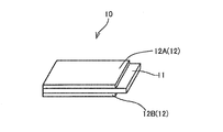
- the negative electrode 10 for an alkaline secondary battery has a base material 11 and negative electrode mixture layers 12A and 12B formed on both surfaces thereof.
- the negative electrode mixture layer 12 may be provided on one side or both sides of the base material 11.
- one side of the base material 11 is formed in the order of the negative electrode mixture layer 12.
- a stacked embodiment may be used. That is, the negative electrode 10 for an alkaline secondary battery is formed by laminating the substrate 11 and the negative electrode mixture layer 12 provided on one or both surfaces of the substrate 11 at least in this order.
- the negative electrode mixture layer 12 is formed by applying a mixture ink containing a conductive agent on the base material 11.
- the base material 11 is a flexible metal plate member.
- the base material 11 is, for example, a base material made of a foil-shaped current collector obtained by thinly casting a metal and having a smooth surface and an end surface. Therefore, the base material 11 does not include a foamed nickel or a material having irregularities due to a porous structure disadvantageous to the formation of the negative electrode mixture layer 12, but a material having a two-dimensional structure and a perforated hole (for example, a punching plate). Including.
- nickel is preferable from the viewpoint of alkali electrolyte resistance. From the viewpoint of cost, it is preferable that the surface of the iron material is nickel-plated to prevent corrosion by the electrolytic solution.
- a flat foil having a smooth surface is used for applying the negative electrode mixture ink.
- the thickness of the substrate 11 is preferably, for example, not less than 4 ⁇ m and not more than 40 ⁇ m.
- the thickness of the substrate 11 is 4 ⁇ m or more, the strength of the substrate 11 itself is further improved, and the electrode is less likely to be damaged during coating and pressing.
- the thickness of the base material 11 is 40 ⁇ m or less, the strength of the base material 11 itself is easily made appropriate, and the winding of the base material 11 at the time of coating becomes easier.
- the thickness of the base material 11 to, for example, 4 ⁇ m or more and 40 ⁇ m or less, when the negative electrode is pressed (for example, a roll gap of 0 and a pressing pressure of 5 t), wrinkles and peeling cannot be visually confirmed. Durability can be imparted.
- the substrate 11 does not break in production depending on its opening density, and wrinkles or peeling cannot be visually confirmed as a surface state. May exceed the upper limit of the above range as long as it has durability.
- the thickness of the nickel plating is preferably 0.1 ⁇ m or more and 5 ⁇ m or less, more preferably 0.2 ⁇ m or more and 3 ⁇ m or less.
- the thickness of the nickel plating is 0.1 ⁇ m or more, corrosion by the electrolytic solution is less likely to occur.
- the thickness of the nickel plating is 5 ⁇ m or less, it is advantageous in terms of cost.
- the negative electrode mixture layer 12 is a layer provided on the base material 11 and includes at least a negative electrode active material, a conductive agent, and a binder resin.
- the negative electrode mixture layer 12 may contain other additives as long as the effects of the present invention are not impaired.
- the negative electrode mixture layer 12 may contain a radical scavenger such as a hindered amine light stabilizer. When the radical scavenger is contained, the content of the radical scavenger with respect to the active material is from 0.01% by weight to 2.0% by weight.
- the negative electrode mixture layer 12 is formed by applying a mixture ink (a negative electrode composition for an alkaline secondary battery) on the base material 11.
- the mixture ink contains at least a negative electrode active material, a conductive agent, and a binder resin, and may contain a radical scavenger as needed.
- the thickness of the negative electrode mixture layer 12 is, for example, not less than 20 ⁇ m and not more than 120 ⁇ m.
- Negative electrode active material those known as negative electrode active materials for alkaline secondary batteries can be used.
- a hydrogen storage alloy, zinc, cadmium, iron and the like can be mentioned.
- the hydrogen storage alloy is not particularly limited as long as it can store electrochemically generated hydrogen in an electrolytic solution and can easily release the stored hydrogen during discharge, and is appropriately selected depending on the purpose. You.
- the average particle diameter of the negative electrode active material is 0.01 ⁇ m or more and 10 ⁇ m or less as a particle diameter D50 according to a volume-based particle size distribution, and the particle diameter D20 according to the volume-based particle size distribution is 30% or more and 70% or less. That is, when the value of D50 of the cumulative particle size distribution of the negative electrode active material measured by a laser diffraction type particle size distribution analyzer is defined as the particle size X, and the value of D20 is defined as the particle size Y, the particle size X is 0.01 ⁇ m or more and 10 ⁇ m or less. And the particle diameter Y is in the range of 30% to 70% of the particle diameter X.
- the particle diameter X is preferably from 0.1 ⁇ m to 10 ⁇ m.
- the term “average particle diameter” refers to a mixture of particles, water and a dispersion, for example, a particle size distribution meter of dynamic light scattering system (“Microtrac MT3100II” manufactured by Microtrac Bell Co., Ltd.) ) Is used to calculate the average particle diameter (median diameter) of 50% when the volume ratio of the particles is integrated from the finer ones in the volume-based particle size distribution as “D50”. , 20% is defined as “D20”.
- the ratio of the active material to the total nonvolatile components of the mixture ink is preferably from 80% by weight to 98% by weight, and more preferably from 85% by weight to 95% by weight.
- the mixture ink contains a conductive agent.
- the conductive agent include nickel powder, cobalt oxide, cobalt hydroxide, carbon, and the like, and two or more of these can be used in combination.
- carbon conductive agents are preferable, and graphite and particulate carbon are also preferable.
- the carbon conductive agent include carbon black, graphite, carbon nanotube, carbon fiber, and fullerenes.
- the carbon black includes, for example, amorphous carbon (amorphous carbon) and particulate carbon.
- the particulate carbon include graphitized carbon, acetylene black, Ketjen black, and furnace black. Among these, amorphous carbon, graphitized carbon, acetylene black and furnace black are preferred.
- the carbon black is furnace black, which is produced by continuously pyrolyzing a gas or liquid raw material in a reaction furnace, particularly Ketjen black using ethylene heavy oil as a raw material.
- Preferred are channel black which is rapidly cooled and deposited, thermal black obtained by periodically repeating combustion and thermal decomposition using gas as a raw material, and particularly acetylene black using acetylene gas as a raw material.
- carbon black that has been subjected to an oxidation treatment and hollow carbon, which are commonly used can also be used. Carbon black can be used alone or in combination of two or more. It should be noted that those obtained by further performing a heat treatment (graphitization treatment) on these carbon blacks are graphitized carbon.
- the average primary particle diameter of the carbon black is preferably from 0.01 ⁇ m to 0.3 ⁇ m.
- the average primary particle diameter is obtained by averaging the numerical values of 10 to 50 particles from an image appropriately enlarged to 10,000 to 100,000 times using a transmission electron microscope (TEM). Further, as the value of the specific surface area of carbon black increases, the number of contact points between carbon black particles increases, which is advantageous in lowering the internal resistance of the electrode.
- specific surface area determined from the adsorption of nitrogen (BET) preferably from 20 m 2 / g or more 1500 m 2 / g or less, more preferably 50 m 2 / g or more 1500m 2 / g, 100m 2 / g It is more preferably at least 1500 m 2 / g. If carbon black having a specific surface area of less than 20 m 2 / g is used, it may be difficult to obtain sufficient conductivity, and carbon black exceeding 1500 m 2 / g is difficult to obtain in the market.
- Examples of commercially available carbon black include, for example, Toka Black # 4300, # 4400, # 4500, # 5500 (furnace black, manufactured by Tokai Carbon Co., Ltd.), Printex L, etc. (furnace black, manufactured by Degussa Co., Ltd.), Raven 7000, 5750, 5250, 5000 ULTRA III, 5000 ULTRA, etc., Conductex SC ULTRA, Conductex 975 ULTRA, etc., PUER BLACK 100, 115, 205, etc.
- the binder resin is used for binding the negative electrode active materials when forming the negative electrode mixture layer 12 and for improving the adhesion to the base material.
- An acrylic resin is preferable as the binder resin, and examples of such a resin include a polymer emulsion.
- the binder resin is, for example, preferably a polymer emulsion having a glass transition temperature of ⁇ 20 ° C. or more and 20 ° C. or less.
- a polymer emulsion for example, 1% by weight or more and 5% by weight or less of a first monomer containing a hydratable functional group and 20% by weight or more and 60% by weight or less of a second monomer containing an aromatic ring And a third monomer containing no hydratable functional group or aromatic ring in an amount of 35% by weight or more and 79% by weight or less, and is preferably an acrylic emulsion synthesized by emulsion polymerization of the monomer mixture.
- the negative electrode mixture layer 12 contains this emulsion, the conductivity of the negative electrode is further improved, and the charge / discharge cycle characteristics (cycle life) are further improved.
- the first monomer is a monomer containing a hydrophilic functional group.
- the amount of the first monomer used is preferably 1% by weight or more and 5% by weight or less, more preferably 2% by weight or more and 4% by weight or less based on all monomers.
- the content is 1% by weight or more, the chemical stability is further improved due to the effect of hydration with water molecules. Further, when the content is 5% by weight or less, the stability at the time of emulsion polymerization is further increased. That is, the fluidity of the emulsion increases, and the emulsion tends to hardly aggregate.
- the second monomer will be described.
- the amount of the second monomer used is preferably 20% by weight or more and 60% by weight or less, more preferably 25% by weight or more and 55% by weight or less based on all the monomers.
- the content is 20% by weight or more, the alkali resistance of the polymer is further improved.
- the adhesion to the base material is further improved.
- the third monomer in the present embodiment is a radical polymerizable monomer other than the first monomer and the second monomer.
- W1 weight% of monomer 1
- Tg1 glass transition temperature (K) of a homopolymer that can be formed from monomer 1 alone
- W2 weight% of monomer 2
- Tg2 glass transition temperature (K) of a homopolymer that can be formed only from monomer 2
- Wn weight% of monomer n
- Tgn glass transition temperature (K) of a homopolymer that can be formed only from monomer n
- a radical-polymerizable unsaturated monomer having a radical-polymerizable unsaturated group is used as an emulsifier when polymerizing the radical-polymerizable unsaturated monomer in an aqueous medium
- the composition of the radical-polymerizable unsaturated monomer and the copolymer are specified.
- the emulsifier having a radically polymerizable unsaturated group is not included in the monomer.
- the binder resin in the present embodiment is copolymerized by emulsion polymerization. At the time of copolymerization, it is preferable to use an emulsifier from the viewpoint of polymerization stability.
- the emulsifier is preferably at least 0.1 part by weight and not more than 5 parts by weight, more preferably at least 1 part by weight and not more than 3 parts by weight, based on 100 parts by weight of the total of monomers used.
- the amount of the emulsifier is 0.1 parts by weight or more, the polymerization stability is further improved. Further, when the amount of the emulsifier is 5 parts by weight or less, the alkali resistance of the secondary battery electrode is further improved.
- an anionic emulsifier or a nonionic emulsifier can be used alone or in combination as an emulsifier.
- the emulsifier may be a reactive emulsifier having a radically polymerizable functional group or a non-reactive emulsifier having no radically polymerizable functional group. Alternatively, both can be used in combination.
- the reactive emulsifier is an anionic or nonionic emulsifier having one or more radically polymerizable unsaturated double bonds in the molecule.
- sulfosuccinates commercially available products include, for example, Latemul S-120P and S-180A manufactured by Kao Corporation, Sanyo Chemical Co., Ltd., Eleminol JS-2), and alkylphenol ethers (commercially available products) Aqualon KH-10 and RN-20 manufactured by Daiichi Kogyo Seiyaku Co., Ltd.).
- examples of the non-reactive emulsifier include an anionic non-reactive emulsifier and a nonionic non-reactive emulsifier.
- anionic non-reactive emulsifier examples include polyoxyethylene alkyl phenyl ether sulfate, polyoxyethylene polycyclic phenyl ether sulfate, polyoxyethylene alkyl ether sulfate, and the like.
- examples of the anionic non-reactive emulsifier include Hytenol NF-08 [the number of repeating ethylene oxide units (hereinafter, referred to as the “number of EO units”: 8)], NF-17 (the number of EO units: 17) [Daiichi Kogyo Seiyaku Co., Ltd.], Eleminol CLS-20 (number of EO units: 10), Eleminol ES-12 (number of EO units: 6), ES-30 (number of EO units: 15), ES- 70 (the number of EO units: 35) [all manufactured by Sanyo Chemical Industries, Ltd.] and the like.
- Hytenol NF-08 the number of repeating ethylene oxide units (hereinafter, referred to as the “number of EO units”: 8)
- NF-17 the number of EO units: 17
- Eleminol CLS-20 number of EO units: 10
- Eleminol ES-12 number of EO units: 6
- nonionic non-reactive emulsifiers include polyoxyethylene alkylphenyl ethers such as polyoxyethylene nonyl phenyl ether and polyoxyethylene octyl phenyl ether; polyoxyethylene lauryl ether, polyoxyethylene stearyl ether, and polyoxyethylene lauryl ether.
- Polyoxyethylene alkyl ethers such as ethylene oleyl ether; polyoxy polycyclic phenyl ethers such as polyoxyethylene distyrenated phenyl ether; and polyoxyethylene sorbitan fatty acid esters.
- examples of the nonionic non-reactive emulsifier include Emulgen 1108 (EO unit number: 8), 1118S-70 (EO unit number: 18), 1135S-70 (EO unit number: 35), and 1150S-70 (EO unit number: 35).
- the number of EO units: 50) (all manufactured by Kao Corporation).
- the above non-reactive emulsifiers may be used alone or in combination of two or more.
- a conventionally known reactive emulsifier can be used among the emulsifiers.
- the radical polymerization initiator that can be used in the present embodiment include persulfates such as potassium persulfate, ammonium persulfate, and sodium persulfate.
- the amount of the polymerization initiator used is preferably 0.1 part by weight or more and 1 part by weight or less, preferably 0.2 part by weight or more and 0.8 part by weight or less based on 100 parts by weight of the total of the monomers used for the emulsion polymerization. More preferably, there is. When the amount is 0.1 part by weight or more, the polymerization stability is further improved. When the content is 1 part by weight or less, the water resistance is further improved.
- a redox initiator obtained by combining a peroxide-based initiator and a reducing agent is preferable.
- the redox initiator a combination of a peroxide initiator and a reducing agent is preferable.
- the peroxide initiator include perbutyl H (tertiary butyl hydroperoxide), perbutyl O (tertiary butyl peroxy-2-ethylhexanoate), cumene hydroperoxide, and p-menthane hydroperoxide.
- reducing agent examples include Erbit N (sodium isoascorbate), L-ascorbic acid (vitamin C), sodium sulfite, sodium bisulfite, sodium pyrosulfite (SMBS), and sodium hyposulfite (hydrosulfite).
- the mixture ink (negative electrode composition for an alkaline secondary battery) preferably contains 0.05 to 20 parts by weight of a binder resin with respect to 100 parts by weight of the active material, and 0.1 to 10 parts by weight. Parts or less is more preferable. If the amount is less than 0.05 parts by weight, the binding force between the active materials is reduced, and as a result, the contact between the active material and the base material 11 is not maintained, and the utilization rate of the positive electrode may be reduced. If the amount exceeds 20 parts by weight, the ratio of the active material in the mixture ink decreases, and the energy density of the electrode tends to decrease. Furthermore, an increase in the proportion of the polymer that is difficult to conduct electricity may increase the electric resistance of the electrode.
- a film-forming aid an antifoaming agent, a leveling agent, a dispersant, a preservative, a pH adjuster, a viscosity adjuster, and the like can be added to the mixture ink.
- the viscosity of the mixture ink can be appropriately selected depending on the coating method, but is preferably from 100 mPa ⁇ s to 30,000 mPa ⁇ s.
- the method for producing a negative electrode for an alkaline secondary battery includes a step of forming a negative electrode mixture layer 12 on a substrate 11.
- a mixture ink (a negative electrode composition for an alkaline secondary battery) containing a binder resin, an active material, and a conductive agent is applied on the base material 11, and dried. It is done.
- the electrode of the negative electrode 10 for an alkaline secondary battery may be subjected to a press treatment using a lithographic press, a calendar roll, or the like. Thereby, the adhesion between the base material 11 and the negative electrode mixture layer 12 is further improved.
- a disperser or a mixer generally used for pigment dispersion or the like can be used.
- mixers such as a disper, a homomixer, or a planetary mixer; homogenizers such as "CLEARMIX" manufactured by M Technique Co., Ltd.
- FILMIX manufactured by PRIMIX
- a paint conditioner manufactured by Red Devil Co., Ltd.
- a ball mill a sand mill (“Dynomill” manufactured by Shinmaru Enterprises Co., Ltd.), an attritor, a pearl mill (“DCP mill” manufactured by Eirich Co., Ltd.), or a co-ball mill
- a wet jet mill (Genus) "Genus PY” manufactured by Sugino Machine Co., Ltd., “Starburst” manufactured by Sugino Machine Co., Ltd., “Nanomizer” manufactured by Nanomizer Co., Ltd.), “Clear SS-5" manufactured by M-Technic Co., Ltd., or Nara Machinery Co., Ltd.
- Medialess dispersing machine such as “MICROS”; or Other roll mill of, but not limited thereto.
- a disperser that has been subjected to a treatment for preventing metal from mixing from the disperser.
- a media type disperser a method in which an agitator and a vessel are made of a ceramic or resin, or a metal agitator and a disperser in which the surface of a vessel is subjected to treatment such as tungsten carbide spraying or resin coating. It is preferable to use And, as the medium, it is preferable to use ceramic beads such as glass beads, zirconia beads, or alumina beads. Also, when a roll mill is used, it is preferable to use a ceramic roll. As the dispersing device, only one type may be used, or a plurality of types of devices may be used in combination.
- An alkaline secondary battery provided with the negative electrode for an alkaline secondary battery of the present embodiment includes the negative electrode for an alkaline secondary battery of the present embodiment, a positive electrode, an electrolytic solution, and a separator.
- the positive electrode comprises a substrate, a primer layer provided on one or both surfaces of the substrate, and a positive electrode mixture layer laminated at least in this order.
- the primer layer is formed by applying a primer composition to one or both surfaces of a substrate, and the positive electrode mixture layer is formed by applying a mixture ink containing a conductive agent on the primer layer. It is formed by being done.
- the shape of the alkaline secondary battery provided with the negative electrode for an alkaline secondary battery of the present embodiment may be various shapes according to the purpose of use, such as a paper type, a cylindrical type, a coin type, a button type, or a stacked type. it can.
- Examples of the electrolyte include an aqueous solution of potassium hydroxide, and a solution obtained by adding sodium hydroxide or lithium hydroxide to an aqueous solution of potassium hydroxide.
- Examples of the separator include, but are not limited to, polyethylene nonwoven fabric, polypropylene nonwoven fabric, polyamide nonwoven fabric, and those obtained by subjecting them to a hydrophilic treatment.
- the alkaline secondary battery provided with the negative electrode for an alkaline secondary battery of the present embodiment can be preferably used for applications such as a substation, a bus, a truck, and a train.
- TOCRYL S-171 manufactured by Toyochem Co., Ltd.
- a negative electrode ink (a negative electrode composition for an alkaline secondary battery) was prepared.
- a negative electrode ink is applied to both sides of a base material made of a Ni-plated steel sheet having a thickness of 15 ⁇ m with an applicator so as to have a basis weight of 200 g / m 2 , respectively.
- the layer was formed, and the negative electrode of Example 1 was produced. That is, in the production of the negative electrode, the negative electrode mixture layer was formed such that the total thickness of the negative electrode mixture layer was 150 ⁇ m and the basis weight of the negative electrode active material in the negative electrode mixture layer was 450 g / m 2 . Therefore, the negative electrode thickness of Example 1, the following Examples 2 to 10, and Comparative Examples 1 to 4 is 215 ⁇ m.
- primer composition As a conductive material, 100 parts of leaf-like graphite (UP-20, manufactured by Nippon Graphite Industry Co., Ltd., average particle diameter 25 ⁇ m, aspect ratio 68) and 5 parts of a dispersant (Joncryl 70J, manufactured by BASF Corporation) are used. Pure water was added so that the residual solid content after the addition and drying became 30%, and the primer composition was adjusted. Thereafter, this primer composition was subjected to a 20-pass dispersion treatment using a bead mill.
- leaf-like graphite UP-20, manufactured by Nippon Graphite Industry Co., Ltd., average particle diameter 25 ⁇ m, aspect ratio 68
- dispersant Joncryl 70J, manufactured by BASF Corporation
- a primer composition was applied to both sides of a substrate made of a 15- ⁇ m-thick Ni-plated steel sheet with an applicator, and then dried to form a primer layer.
- the primer layer was formed with a thickness per side of 1 ⁇ m.
- a positive electrode ink was applied to each of the primer layers with an applicator so as to have a basis weight of 150 g / m 2, and a positive electrode mixture layer was formed so as to have a dry thickness of 100 ⁇ m, respectively, to produce a positive electrode. . That is, in this positive electrode, the positive electrode mixture layer was formed such that the total thickness of the positive electrode mixture layer was 200 ⁇ m and the basis weight of the positive electrode active material in the positive electrode mixture layer was 300 g / m 2 . Therefore, the total thickness of the positive electrodes of Example 1, the following Examples 2 to 11, and Comparative Examples 1 to 4 is 217 ⁇ m.
- a negative electrode, a sulfonated PP nonwoven fabric separator having a thickness of 200 ⁇ m, and a positive electrode were stacked in this order on a coin cell, an alkaline electrolyte was injected, cured for one day, and the electrolyte was infiltrated to produce an alkaline secondary battery of Example 1.
- Example 2 A negative electrode composition for an alkaline secondary battery of Example 2 was produced in the same manner as in Example 1, except that the particle diameter Y of the active material (A) was changed to 5.6 ⁇ m. Thereafter, using the negative electrode composition for an alkaline secondary battery of Example 2, a negative electrode for an alkaline secondary battery of Example 2 was produced in the same manner as in Example 1. Thereafter, using the negative electrode for an alkaline secondary battery of Example 2, an alkaline secondary battery of Example 2 was produced in the same manner as in Example 1.
- Example 3 A negative electrode composition for an alkaline secondary battery of Example 3 was produced in the same manner as in Example 1, except that the particle size Y of the active material (A) was changed to 4.8 ⁇ m. Thereafter, using the negative electrode composition for an alkaline secondary battery of Example 3, a negative electrode for an alkaline secondary battery of Example 3 was produced in the same manner as in Example 1. Thereafter, using the negative electrode for an alkaline secondary battery of Example 3, an alkaline secondary battery of Example 3 was produced in the same manner as in Example 1.
- Example 4 A negative electrode composition for an alkaline secondary battery of Example 4 was prepared in the same manner as in Example 3, except that 10 parts of graphite was added instead of 10 parts of carbon as the conductive agent (C). Thereafter, using the negative electrode composition for an alkaline secondary battery of Example 4, a negative electrode for an alkaline secondary battery of Example 4 was produced in the same manner as in Example 1. Thereafter, using the negative electrode for an alkaline secondary battery of Example 4, an alkaline secondary battery of Example 4 was produced in the same manner as in Example 1.
- Negative electrode composition for alkaline secondary battery of Example 5 in the same manner as in Example 3 except that 9 parts of carbon and 1 part of carbon nanotube (CNT) were added instead of 10 parts of carbon as the conductive agent (C). was prepared. Thereafter, using the negative electrode composition for an alkaline secondary battery of Example 5, a negative electrode for an alkaline secondary battery of Example 5 was produced in the same manner as in Example 1. Thereafter, using the negative electrode for an alkaline secondary battery of Example 5, an alkaline secondary battery of Example 5 was produced in the same manner as in Example 1.
- CNT carbon nanotubes
- Example 7 A negative electrode composition for an alkaline secondary battery of Example 7 was produced in the same manner as in Example 3, except that 10 parts of carbon nanotubes (CNT) were added as the conductive agent (C) instead of 10 parts of carbon. Thereafter, using the negative electrode composition for an alkaline secondary battery of Example 7, a negative electrode for an alkaline secondary battery of Example 7 was produced in the same manner as in Example 1. Thereafter, an alkaline secondary battery of Example 7 was produced in the same manner as in Example 1 using the negative electrode for an alkaline secondary battery of Example 7.
- CNT carbon nanotubes
- Negative electrode composition for an alkaline secondary battery of Example 8 in the same manner as in Example 1 except that the average particle diameter X of the active material (A) was 10 ⁇ m and the particle diameter Y of the active material (A) was 7 ⁇ m. was prepared. Thereafter, using the negative electrode composition for an alkaline secondary battery of Example 8, a negative electrode for an alkaline secondary battery of Example 8 was produced in the same manner as in Example 1. Thereafter, an alkaline secondary battery of Example 8 was produced in the same manner as in Example 1 using the negative electrode for an alkaline secondary battery of Example 8.
- Negative electrode composition for an alkaline secondary battery of Example 9 in the same manner as in Example 1 except that the average particle diameter X of the active material (A) was 10 ⁇ m and the particle diameter Y of the active material (A) was 3 ⁇ m. was prepared. Thereafter, using the negative electrode composition for an alkaline secondary battery of Example 9, a negative electrode for an alkaline secondary battery of Example 9 was produced in the same manner as in Example 1. Thereafter, using the negative electrode for an alkaline secondary battery of Example 9, an alkaline secondary battery of Example 9 was produced in the same manner as in Example 1.
- Negative electrode composition for alkaline secondary battery of Example 10 in the same manner as in Example 1 except that the average particle diameter X of the active material (A) was 10 ⁇ m and the particle diameter Y of the active material (A) was 5 ⁇ m. was prepared. Thereafter, using the negative electrode composition for an alkaline secondary battery of Example 10, a negative electrode for an alkaline secondary battery of Example 10 was produced in the same manner as in Example 1. Thereafter, an alkaline secondary battery of Example 10 was produced in the same manner as in Example 1 using the negative electrode for an alkaline secondary battery of Example 10.
- Example 11 A negative electrode composition for an alkaline secondary battery was produced in the same manner as in Example 10. Thereafter, using the prepared negative electrode composition for an alkaline secondary battery, a negative electrode for an alkaline secondary battery of Example 11 was prepared in the same manner as in Example 10 except that the thickness of the base material was changed to 45 ⁇ m. Thereafter, using the negative electrode for an alkaline secondary battery of Example 11, an alkaline secondary battery of Example 11 was produced in the same manner as in Example 10.
- Comparative Example 1 A negative electrode composition for an alkaline secondary battery of Comparative Example 1 was produced in the same manner as in Example 1, except that the average particle diameter X of the active material (A) was 15 ⁇ m and the particle diameter Y was 6 ⁇ m. Thereafter, using the negative electrode composition for an alkaline secondary battery of Comparative Example 1, a negative electrode for an alkaline secondary battery of Comparative Example 1 was produced in the same manner as in Example 1. Thereafter, an alkaline secondary battery of Comparative Example 1 was produced in the same manner as in Example 1 using the negative electrode for an alkaline secondary battery of Comparative Example 1.
- Comparative Example 2 A negative electrode composition for an alkaline secondary battery of Comparative Example 2 was produced in the same manner as in Example 1, except that the particle size Y of the active material (A) was changed to 6 ⁇ m. Thereafter, using the negative electrode composition for an alkaline secondary battery of Comparative Example 2, a negative electrode for an alkaline secondary battery of Comparative Example 2 was produced in the same manner as in Example 1. Thereafter, an alkaline secondary battery of Comparative Example 2 was produced in the same manner as in Example 1 using the negative electrode for an alkaline secondary battery of Comparative Example 2.
- Comparative Example 3 A negative electrode composition for an alkaline secondary battery of Comparative Example 3 was produced in the same manner as in Example 1, except that the particle diameter Y of the active material (A) was 1.8 ⁇ m. Thereafter, using the negative electrode composition for an alkaline secondary battery of Comparative Example 3, a negative electrode for an alkaline secondary battery of Comparative Example 3 was produced in the same manner as in Example 1. Thereafter, an alkaline secondary battery of Comparative Example 3 was produced in the same manner as in Example 1 using the negative electrode for an alkaline secondary battery of Comparative Example 3.
- Comparative Example 4 A negative electrode composition for an alkaline secondary battery of Comparative Example 4 was prepared in the same manner as in Example 3, except that the conductive agent (C) was not included. Thereafter, using the negative electrode composition for an alkaline secondary battery of Comparative Example 4, a negative electrode for an alkaline secondary battery of Comparative Example 4 was produced in the same manner as in Example 1. Thereafter, an alkaline secondary battery of Comparative Example 4 was produced in the same manner as in Example 1 using the negative electrode for an alkaline secondary battery of Comparative Example 4.
- the comprehensive evaluation is an evaluation obtained by integrating the respective evaluations of “cycle life” and “output characteristics”. Specifically, examples indicated by “ ⁇ ”and“ ⁇ ” indicate that “cycle life” and “output characteristics” are good, and examples indicated by “ ⁇ ” and “XX” indicate “ It shows that the "cycle life” and “output characteristics” are not preferable.
- Examples 1 to 11 in which the hydrogen storage alloy contained fine powder having a predetermined particle size distribution had good cycle life and output characteristics, and had a higher output than Comparative Examples 1 to 4. And improved both input / output performance and durability.
- Comparative Examples 1 to 4 when the amount of fine powder having a predetermined particle size distribution in the hydrogen storage alloy was too large (Comparative Examples 1 and 2), the output characteristics were poor, and as in Comparative Example 3, the amount of fine powder having a predetermined particle size distribution was too small. And the cycle life was not good.
Landscapes
- Chemical & Material Sciences (AREA)
- Chemical Kinetics & Catalysis (AREA)
- Electrochemistry (AREA)
- General Chemical & Material Sciences (AREA)
- Engineering & Computer Science (AREA)
- Materials Engineering (AREA)
- Manufacturing & Machinery (AREA)
- Battery Electrode And Active Subsutance (AREA)
- Cell Electrode Carriers And Collectors (AREA)
Abstract
The present invention provides: a negative electrode for alkaline secondary batteries, which is capable of achieving a good balance between the output characteristics and the cycle life at high levels; and a composition which constitutes this negative electrode. A negative electrode (10) for alkaline secondary batteries according to the present invention comprises an active material, a binder resin and a conductive agent that contains a conductive carbon material; and if the value of D50 in the cumulative particle size distribution of the active material as determined by using a laser diffraction particle size distribution measuring instrument is taken as the average particle diameter X and the value of D20 is taken as the particle diameter Y, the average particle diameter X is 10 μm or less and the value of the particle diameter Y is from 30% to 70% of the average particle diameter X.
Description
本発明は、アルカリ二次電池用負極組成物及びアルカリ二次電池用負極に関する。
The present invention relates to a negative electrode composition for an alkaline secondary battery and a negative electrode for an alkaline secondary battery.
近年、アルカリ二次電池は、HEV(Hybrid Electric Vehicle)や電動工具など高出力が求められる用途に高い需要がある。高出力化手法としては、特許文献1~3に記載されるような技術が挙げられ、電極の対向面積や負極合金の粒度分布を揃える手法が検討されてきた。
In recent years, alkaline secondary batteries have been in great demand for applications requiring high output, such as HEV (Hybrid Electric Vehicle) and electric tools. Techniques for increasing the output include techniques as described in Patent Documents 1 to 3, and techniques for making the facing area of the electrodes and the particle size distribution of the negative electrode alloy uniform have been studied.
しかしながら、特許文献1~3に記載されるような技術では、出力特性と耐久性(サイクル寿命)の両立の向上に改善の余地があった。
本発明は、上記事情に鑑みてなされたものであり、出力特性及びサイクル寿命の両立が高いレベルで実現可能なアルカリ二次電池用負極及びそれを構成する組成物を提供することを目的とする。 However, in the technologies described in Patent Documents 1 to 3, there is room for improvement in improving both output characteristics and durability (cycle life).
The present invention has been made in view of the above circumstances, and an object of the present invention is to provide a negative electrode for an alkaline secondary battery, which is capable of realizing a high level of compatibility between output characteristics and cycle life at a high level, and a composition constituting the negative electrode. .
上記課題を解決するための本発明の一態様のアルカリ二次電池用負極組成物は、活物質と、
バインダー樹脂と、
導電性炭素材料を含む導電剤と、を有し、
上記活物質をレーザー回折式粒度分布計で測定した累積粒度分布のD50の値を平均粒子径Xとし、D20の値を粒子径Yとした場合に、
上記平均粒子径Xが10μm以下であり、かつ上記粒子径Yの値が上記平均粒子径Xの30%以上70%以下の範囲内である。 To solve the above problems, the negative electrode composition for an alkaline secondary battery of one embodiment of the present invention includes an active material,
A binder resin,
And a conductive agent containing a conductive carbon material,
When the value of D50 of the cumulative particle size distribution of the active material measured by a laser diffraction type particle size distribution analyzer is defined as an average particle size X, and the value of D20 is defined as a particle size Y,
The average particle diameter X is 10 μm or less, and the value of the particle diameter Y is in the range of 30% to 70% of the average particle diameter X.
また、上記課題を解決するためのアルカリ二次電池用負極の一態様としては、シート状金属基材上に、アルカリ二次電池用負極組成物が積層され、
該アルカリ二次電池用負極組成物が、
活物質と、
バインダー樹脂と、
導電性炭素材料を含む導電剤と、を有し、
上記活物質をレーザー回折式粒度分布計で測定した累積粒度分布のD50の値を平均粒子径Xとし、D20の値を粒子径Yとした場合に、
上記平均粒子径Xが10μm以下であり、かつ上記粒子径Yの値が上記平均粒子径Xの30%以上70%以下の範囲内である。 Further, as one embodiment of the negative electrode for an alkaline secondary battery to solve the above problem, a negative electrode composition for an alkaline secondary battery is laminated on a sheet-like metal substrate,
The negative electrode composition for an alkaline secondary battery,
Active material,
A binder resin,
And a conductive agent containing a conductive carbon material,
When the value of D50 of the cumulative particle size distribution of the active material measured by a laser diffraction type particle size distribution analyzer is defined as an average particle size X, and the value of D20 is defined as a particle size Y,
The average particle diameter X is 10 μm or less, and the value of the particle diameter Y is in the range of 30% to 70% of the average particle diameter X.
本発明の一態様によれば、出力特性及びサイクル寿命の両立が高いレベルで実現可能なアルカリ二次電池用負極及びそれを構成する組成物を提供することができる。
According to one embodiment of the present invention, it is possible to provide a negative electrode for an alkaline secondary battery and a composition constituting the negative electrode, which can achieve a high level of both output characteristics and cycle life.
以下、本発明の一実施形態について、図面を参照して説明する。
以下の詳細な説明では、本発明の実施形態について、完全な理解を提供するように、特定の細部について記載する。しかしながら、かかる特定の細部が無くとも、一つ以上の実施形態が実施可能であることは明確である。また、図面を簡潔なものとするために、周知の構造及び装置を、略図で表す場合がある。 Hereinafter, an embodiment of the present invention will be described with reference to the drawings.
In the following detailed description, specific details are set forth in order to provide a thorough understanding of embodiments of the invention. It is apparent, however, that one or more embodiments may be practiced without these specific details. In other instances, well-known structures and devices are represented in schematic form in order to simplify the figures.
(アルカリ二次電池用負極)
図1に示すように、本実施形態のアルカリ二次電池用負極10は、基材11と、その両面に形成された負極合材層12A,12Bとを有する。ここで、負極合材層12は、基材11の片面又は両面に設けられればよく、アルカリ二次電池用負極10の構成としては、基材11の片面に、負極合材層12の順で積層された態様でもよい。すなわち、アルカリ二次電池用負極10は、基材11と、基材11の片面又は両面に設けられた負極合材層12が少なくともこの順で積層してなる。なお、負極合材層12は、基材11上に導電剤が含まれた合材インキが塗工されることによって形成される。 (Negative electrode for alkaline secondary battery)
As shown in FIG. 1, thenegative electrode 10 for an alkaline secondary battery according to the present embodiment has a base material 11 and negative electrode mixture layers 12A and 12B formed on both surfaces thereof. Here, the negative electrode mixture layer 12 may be provided on one side or both sides of the base material 11. As a configuration of the negative electrode 10 for an alkaline secondary battery, one side of the base material 11 is formed in the order of the negative electrode mixture layer 12. A stacked embodiment may be used. That is, the negative electrode 10 for an alkaline secondary battery is formed by laminating the substrate 11 and the negative electrode mixture layer 12 provided on one or both surfaces of the substrate 11 at least in this order. The negative electrode mixture layer 12 is formed by applying a mixture ink containing a conductive agent on the base material 11.
図1に示すように、本実施形態のアルカリ二次電池用負極10は、基材11と、その両面に形成された負極合材層12A,12Bとを有する。ここで、負極合材層12は、基材11の片面又は両面に設けられればよく、アルカリ二次電池用負極10の構成としては、基材11の片面に、負極合材層12の順で積層された態様でもよい。すなわち、アルカリ二次電池用負極10は、基材11と、基材11の片面又は両面に設けられた負極合材層12が少なくともこの順で積層してなる。なお、負極合材層12は、基材11上に導電剤が含まれた合材インキが塗工されることによって形成される。 (Negative electrode for alkaline secondary battery)
As shown in FIG. 1, the
<基材>
基材11は、可撓性を備えた金属製の板状部材である。基材11は、例えば、金属を薄く打ち延ばした箔状集電体からなり、表面及び端面が平滑である基材が挙げられる。そのため、基材11としては、発泡ニッケルや、負極合材層12の形成に不利な多孔質体構造による凹凸を有するものは含まず、二次元構造で孔加工を有するもの(例えばパンチングプレート)を含む。 <Substrate>
Thebase material 11 is a flexible metal plate member. The base material 11 is, for example, a base material made of a foil-shaped current collector obtained by thinly casting a metal and having a smooth surface and an end surface. Therefore, the base material 11 does not include a foamed nickel or a material having irregularities due to a porous structure disadvantageous to the formation of the negative electrode mixture layer 12, but a material having a two-dimensional structure and a perforated hole (for example, a punching plate). Including.
基材11は、可撓性を備えた金属製の板状部材である。基材11は、例えば、金属を薄く打ち延ばした箔状集電体からなり、表面及び端面が平滑である基材が挙げられる。そのため、基材11としては、発泡ニッケルや、負極合材層12の形成に不利な多孔質体構造による凹凸を有するものは含まず、二次元構造で孔加工を有するもの(例えばパンチングプレート)を含む。 <Substrate>
The
[基材の材質]
基材11の材質としては、アルカリ電解液耐性の観点から、ニッケルが好ましい。また、コストの観点から、鉄材質の表面を電解液による腐食防止のためにニッケルメッキしたものが好ましい。
基材11には、負極合材インキを塗工するために表面が平滑な平板状の箔が用いられる。 [Material of base material]
As the material of thebase material 11, nickel is preferable from the viewpoint of alkali electrolyte resistance. From the viewpoint of cost, it is preferable that the surface of the iron material is nickel-plated to prevent corrosion by the electrolytic solution.
For thebase material 11, a flat foil having a smooth surface is used for applying the negative electrode mixture ink.
基材11の材質としては、アルカリ電解液耐性の観点から、ニッケルが好ましい。また、コストの観点から、鉄材質の表面を電解液による腐食防止のためにニッケルメッキしたものが好ましい。
基材11には、負極合材インキを塗工するために表面が平滑な平板状の箔が用いられる。 [Material of base material]
As the material of the
For the
[基材の厚み]
また、基材11の厚みは、例えば、4μm以上40μm以下であることが好ましい。基材11の厚みが4μm以上になると、基材11自身の強度がより向上し、塗工及びプレス加工時に電極の破損が生じにくくなる。また、基材11の厚みが40μm以下であれば、基材11自身の強度を適切にしやすく、塗工時の基材11の巻き取りがより容易になる。具体的には、基材11の厚みを、例えば4μm以上40μm以下とすることで、負極をプレスした際(例えばロールギャップ0、プレス圧5t)の表面状態としてシワや剥離が目視で確認できない程度の耐久性を付与することができる。なお、基材11として、例えば、二次元構造で孔加工を有するものを採用した場合には、その開口密度に応じて、製造上破断せず、表面状態としてシワや剥離が目視で確認できない程度の耐久性を有する限りにおいて上記範囲の上限を超えることがある。 [Substrate thickness]
Further, the thickness of thesubstrate 11 is preferably, for example, not less than 4 μm and not more than 40 μm. When the thickness of the substrate 11 is 4 μm or more, the strength of the substrate 11 itself is further improved, and the electrode is less likely to be damaged during coating and pressing. Further, when the thickness of the base material 11 is 40 μm or less, the strength of the base material 11 itself is easily made appropriate, and the winding of the base material 11 at the time of coating becomes easier. Specifically, by setting the thickness of the base material 11 to, for example, 4 μm or more and 40 μm or less, when the negative electrode is pressed (for example, a roll gap of 0 and a pressing pressure of 5 t), wrinkles and peeling cannot be visually confirmed. Durability can be imparted. In the case where, for example, a substrate having a two-dimensional structure and a hole is used as the substrate 11, the substrate 11 does not break in production depending on its opening density, and wrinkles or peeling cannot be visually confirmed as a surface state. May exceed the upper limit of the above range as long as it has durability.
また、基材11の厚みは、例えば、4μm以上40μm以下であることが好ましい。基材11の厚みが4μm以上になると、基材11自身の強度がより向上し、塗工及びプレス加工時に電極の破損が生じにくくなる。また、基材11の厚みが40μm以下であれば、基材11自身の強度を適切にしやすく、塗工時の基材11の巻き取りがより容易になる。具体的には、基材11の厚みを、例えば4μm以上40μm以下とすることで、負極をプレスした際(例えばロールギャップ0、プレス圧5t)の表面状態としてシワや剥離が目視で確認できない程度の耐久性を付与することができる。なお、基材11として、例えば、二次元構造で孔加工を有するものを採用した場合には、その開口密度に応じて、製造上破断せず、表面状態としてシワや剥離が目視で確認できない程度の耐久性を有する限りにおいて上記範囲の上限を超えることがある。 [Substrate thickness]
Further, the thickness of the
[ニッケルメッキの厚み]
上述したように、基材11としてニッケルメッキしたものを用いる場合、ニッケルメッキの厚みは、0.1μm以上5μm以下であることが好ましく、0.2μm以上3μm以下がより好ましい。ニッケルメッキの厚みが、0.1μm以上になると、電解液による腐食が生じにくくなる。また、ニッケルメッキの厚みが5μm以下になると、コスト的に有利になる。 [Nickel plating thickness]
As described above, when a nickel-plated substrate is used as thebase material 11, the thickness of the nickel plating is preferably 0.1 μm or more and 5 μm or less, more preferably 0.2 μm or more and 3 μm or less. When the thickness of the nickel plating is 0.1 μm or more, corrosion by the electrolytic solution is less likely to occur. Further, when the thickness of the nickel plating is 5 μm or less, it is advantageous in terms of cost.
上述したように、基材11としてニッケルメッキしたものを用いる場合、ニッケルメッキの厚みは、0.1μm以上5μm以下であることが好ましく、0.2μm以上3μm以下がより好ましい。ニッケルメッキの厚みが、0.1μm以上になると、電解液による腐食が生じにくくなる。また、ニッケルメッキの厚みが5μm以下になると、コスト的に有利になる。 [Nickel plating thickness]
As described above, when a nickel-plated substrate is used as the
<負極合材層>
負極合材層12は、基材11上に設けられる層であり、少なくとも負極活物質、導電剤、及びバインダー樹脂を含む。負極合材層12は、本発明の効果を損なわない範囲で他の添加物を含んでもよく、例えば、ヒンダードアミン系光安定剤等のラジカル捕捉剤を含んでもよい。上記ラジカル捕捉剤を含む場合、ラジカル捕捉剤の上記活物質に対する含有率は、0.01重量%以上2.0重量%以下である。
負極合材層12は、基材11上に合材インキ(アルカリ二次電池用負極組成物)が塗工されることによって形成される。すなわち、この合材インキは、少なくとも負極活物質、導電剤、及びバインダー樹脂を含有し、必要に応じてラジカル捕捉剤を含有してもよい。負極合材層12の厚みは、例えば、20μm以上120μm以下である。 <Negative electrode mixture layer>
The negativeelectrode mixture layer 12 is a layer provided on the base material 11 and includes at least a negative electrode active material, a conductive agent, and a binder resin. The negative electrode mixture layer 12 may contain other additives as long as the effects of the present invention are not impaired. For example, the negative electrode mixture layer 12 may contain a radical scavenger such as a hindered amine light stabilizer. When the radical scavenger is contained, the content of the radical scavenger with respect to the active material is from 0.01% by weight to 2.0% by weight.
The negativeelectrode mixture layer 12 is formed by applying a mixture ink (a negative electrode composition for an alkaline secondary battery) on the base material 11. That is, the mixture ink contains at least a negative electrode active material, a conductive agent, and a binder resin, and may contain a radical scavenger as needed. The thickness of the negative electrode mixture layer 12 is, for example, not less than 20 μm and not more than 120 μm.
負極合材層12は、基材11上に設けられる層であり、少なくとも負極活物質、導電剤、及びバインダー樹脂を含む。負極合材層12は、本発明の効果を損なわない範囲で他の添加物を含んでもよく、例えば、ヒンダードアミン系光安定剤等のラジカル捕捉剤を含んでもよい。上記ラジカル捕捉剤を含む場合、ラジカル捕捉剤の上記活物質に対する含有率は、0.01重量%以上2.0重量%以下である。
負極合材層12は、基材11上に合材インキ(アルカリ二次電池用負極組成物)が塗工されることによって形成される。すなわち、この合材インキは、少なくとも負極活物質、導電剤、及びバインダー樹脂を含有し、必要に応じてラジカル捕捉剤を含有してもよい。負極合材層12の厚みは、例えば、20μm以上120μm以下である。 <Negative electrode mixture layer>
The negative
The negative
[負極活物質]
負極活物質としては、アルカリ二次電池用の負極活物質として公知のものを使用できる。例えば、水素吸蔵合金、亜鉛、カドミウム、鉄などが挙げられる。上記水素吸蔵合金としては、電解液中で電気化学的に発生させた水素を吸蔵でき、かつ放電時にその吸蔵水素を容易に放出できるものであれば特に制限はなく、目的に応じて適宜選択される。 [Negative electrode active material]
As the negative electrode active material, those known as negative electrode active materials for alkaline secondary batteries can be used. For example, a hydrogen storage alloy, zinc, cadmium, iron and the like can be mentioned. The hydrogen storage alloy is not particularly limited as long as it can store electrochemically generated hydrogen in an electrolytic solution and can easily release the stored hydrogen during discharge, and is appropriately selected depending on the purpose. You.
[負極活物質の粒子径]
負極活物質の平均粒子径は、体積基準粒度分布による粒子径D50として、0.01μm以上10μm以下であり、体積基準粒度分布による粒子径D20が、その30%以上70%以下の寸法である。
すなわち、負極活物質をレーザー回折式粒度分布計で測定した累積粒度分布のD50の値を粒子径Xとし、D20の値を粒子径Yとした場合に、粒子径Xが0.01μm以上10μm以下であり、かつ粒子径Yの値が粒子径Xの30%以上70%以下の範囲内であるものが用いられる。 [Particle size of negative electrode active material]
The average particle diameter of the negative electrode active material is 0.01 μm or more and 10 μm or less as a particle diameter D50 according to a volume-based particle size distribution, and the particle diameter D20 according to the volume-based particle size distribution is 30% or more and 70% or less.
That is, when the value of D50 of the cumulative particle size distribution of the negative electrode active material measured by a laser diffraction type particle size distribution analyzer is defined as the particle size X, and the value of D20 is defined as the particle size Y, the particle size X is 0.01 μm or more and 10 μm or less. And the particle diameter Y is in the range of 30% to 70% of the particle diameter X.
なお、粒子径Xは、0.1μm以上10μm以下が好ましい。
ここで、本実施形態で平均粒子径とは、粒子、水及び分散体を混合した混合物を、例えば、動的光散乱方式の粒度分布計(マイクロトラック・ベル(株)製「マイクロトラックMT3100II」)を使用して、体積基準粒度分布において、粒子径の細かいものからその粒子の体積割合を積算していったときに、50%となるところの平均粒子径(メディアン径)を「D50」とし、20%となるところの粒子径を「D20」とする。 The particle diameter X is preferably from 0.1 μm to 10 μm.
Here, in the present embodiment, the term “average particle diameter” refers to a mixture of particles, water and a dispersion, for example, a particle size distribution meter of dynamic light scattering system (“Microtrac MT3100II” manufactured by Microtrac Bell Co., Ltd.) ) Is used to calculate the average particle diameter (median diameter) of 50% when the volume ratio of the particles is integrated from the finer ones in the volume-based particle size distribution as “D50”. , 20% is defined as “D20”.
[負極活物質の配合割合]
活物質が合材インキの不揮発分の合計に占める割合は、80重量%以上98重量%以下が好ましく、85重量%以上95重量%以下がより好ましい。 [Blending ratio of negative electrode active material]
The ratio of the active material to the total nonvolatile components of the mixture ink is preferably from 80% by weight to 98% by weight, and more preferably from 85% by weight to 95% by weight.
[導電剤]
上記合材インキには、導電剤が含まれる。導電剤としては、例えば、ニッケル粉末、酸化コバルト、水酸化コバルト、カーボン等を挙げることができ、これらを2つ又はそれ以上組み合わせて用いることもできる。これらの中でも、カーボンの導電剤が好ましく、黒鉛や、粒子状カーボンも好ましい。
上記カーボンの導電剤としては、カーボンブラック、グラファイト、カーボンナノチューブ、炭素繊維、フラーレン類を挙げることができる。カーボンブラックは、例えば、不定形カーボン(アモルファスカーボン)と粒子状カーボンとがあり、粒子状カーボンとしては、黒鉛化カーボン、アセチレンブラック、ケッチェンブラック、ファーネスブラックが挙げられる。これらの中でも、アモルファスカーボン、黒鉛化カーボン、アセチレンブラック、ファーネスブラックが好ましい。 [Conductive agent]
The mixture ink contains a conductive agent. Examples of the conductive agent include nickel powder, cobalt oxide, cobalt hydroxide, carbon, and the like, and two or more of these can be used in combination. Among these, carbon conductive agents are preferable, and graphite and particulate carbon are also preferable.
Examples of the carbon conductive agent include carbon black, graphite, carbon nanotube, carbon fiber, and fullerenes. The carbon black includes, for example, amorphous carbon (amorphous carbon) and particulate carbon. Examples of the particulate carbon include graphitized carbon, acetylene black, Ketjen black, and furnace black. Among these, amorphous carbon, graphitized carbon, acetylene black and furnace black are preferred.
上記カーボンブラックは、気体又は液体の原料を反応炉中で連続的に熱分解し製造するファーネスブラック、特にエチレン重油を原料としたケッチェンブラック、原料ガスを燃焼させて、その炎をチャンネル鋼底面にあて急冷し析出させたチャンネルブラック、ガスを原料とし燃焼と熱分解を周期的に繰り返すことにより得られるサーマルブラック、特にアセチレンガスを原料とするアセチレンブラックなどが好ましい。また、通常行われている酸化処理されたカーボンブラックや、中空カーボン等も使用できる。カーボンブラックは、単独で、もしくは2種類以上併せて使用することができる。なお、これらのカーボンブラックにさらに熱処理(黒鉛化処理)を行ったものが黒鉛化カーボンである。
The carbon black is furnace black, which is produced by continuously pyrolyzing a gas or liquid raw material in a reaction furnace, particularly Ketjen black using ethylene heavy oil as a raw material. Preferred are channel black which is rapidly cooled and deposited, thermal black obtained by periodically repeating combustion and thermal decomposition using gas as a raw material, and particularly acetylene black using acetylene gas as a raw material. In addition, carbon black that has been subjected to an oxidation treatment and hollow carbon, which are commonly used, can also be used. Carbon black can be used alone or in combination of two or more. It should be noted that those obtained by further performing a heat treatment (graphitization treatment) on these carbon blacks are graphitized carbon.
カーボンブラックの平均一次粒子径は、0.01μm以上0.3μm以下が好ましい。ここで、平均一次粒子径は、透過型電子顕微鏡(TEM)を用いて、1万倍~10万倍に適宜拡大した画像から、10~50個の粒子の数値を平均することで得られる。さらに、カーボンブラックは、その比表面積の値が大きいほど、カーボンブラック粒子どうしの接触点が増えるため、電極の内部抵抗を下げるのに有利となる。具体的には、窒素の吸着量から求められる比表面積(BET)で、20m2/g以上1500m2/g以下が好ましく、50m2/g以上1500m2/g以下がより好ましく、100m2/g以上1500m2/g以下が更に好ましい。比表面積が20m2/gを下回るカーボンブラックを用いると、十分な導電性を得ることが難しくなる場合があり、1500m2/gを超えるカーボンブラックは、市場では入手が困難である。
The average primary particle diameter of the carbon black is preferably from 0.01 μm to 0.3 μm. Here, the average primary particle diameter is obtained by averaging the numerical values of 10 to 50 particles from an image appropriately enlarged to 10,000 to 100,000 times using a transmission electron microscope (TEM). Further, as the value of the specific surface area of carbon black increases, the number of contact points between carbon black particles increases, which is advantageous in lowering the internal resistance of the electrode. Specifically, in specific surface area determined from the adsorption of nitrogen (BET), preferably from 20 m 2 / g or more 1500 m 2 / g or less, more preferably 50 m 2 / g or more 1500m 2 / g, 100m 2 / g It is more preferably at least 1500 m 2 / g. If carbon black having a specific surface area of less than 20 m 2 / g is used, it may be difficult to obtain sufficient conductivity, and carbon black exceeding 1500 m 2 / g is difficult to obtain in the market.
市販のカーボンブラックとしては、例えば、トーカブラック#4300、#4400、#4500、#5500等(東海カーボン(株)製、ファーネスブラック)、プリンテックスL等(デグサ(株)製、ファーネスブラック)、Raven7000、5750、5250、5000ULTRAIII、5000ULTRA等、Conductex SC ULTRA、Conductex 975 ULTRA等、PUER BLACK100、115、205等(コロンビヤン(株)製、ファーネスブラック)、#2350、#2400B、#2600B、#3050B、#3030B、#3230B、#3350B、#3400B、#5400B等(三菱化学(株)製、ファーネスブラック)、MONARCH1400、1300、900、VulcanXC-72R、BlackPearls2000等(キャボット(株)製、ファーネスブラック)、Ensaco250G、Ensaco260G、Ensaco350G、SuperP-Li(TIMCAL(株)製)、ケッチェンブラックEC-300J、EC-600JD(アクゾ(株)製)、デンカブラック、デンカブラックHS-100、FX-35(電気化学工業(株)製、アセチレンブラック)等が挙げられるが、これらに限定されるものではなく、2種以上を組み合わせて用いてもよい。
Examples of commercially available carbon black include, for example, Toka Black # 4300, # 4400, # 4500, # 5500 (furnace black, manufactured by Tokai Carbon Co., Ltd.), Printex L, etc. (furnace black, manufactured by Degussa Co., Ltd.), Raven 7000, 5750, 5250, 5000 ULTRA III, 5000 ULTRA, etc., Conductex SC ULTRA, Conductex 975 ULTRA, etc., PUER BLACK 100, 115, 205, etc. (made by Colombian Corp., furnace black), # 2350, # 2400B, # 2600B, # 2600B, # 2600B, # 2600B # 3030B, # 3230B, # 3350B, # 3400B, # 5400B, etc. (furnace black, manufactured by Mitsubishi Chemical Corporation), MONARCH 1400, 1300, 00, Vulcan XC-72R, BlackPearls2000, etc. (furnace black, manufactured by Cabot Corporation), Ensaco250G, Ensaco260G, Ensaco350G, SuperP-Li (manufactured by TIMCAL), Ketjenblack EC-300J, EC-600JD (Akzo) ), Denka Black, Denka Black HS-100, FX-35 (Acetylene Black, manufactured by Denki Kagaku Kogyo KK) and the like, but are not limited thereto, and two or more types may be used in combination. You may.
[バインダー樹脂]
バインダー樹脂は、負極合材層12を形成する際に、負極活物質同士を結着させる、更には基材に対しての密着性向上のために使用される。バインダー樹脂としては、アクリル系樹脂が好ましく、このような樹脂としては、例えば、ポリマーエマルションが挙げられる。 [Binder resin]
The binder resin is used for binding the negative electrode active materials when forming the negativeelectrode mixture layer 12 and for improving the adhesion to the base material. An acrylic resin is preferable as the binder resin, and examples of such a resin include a polymer emulsion.
バインダー樹脂は、負極合材層12を形成する際に、負極活物質同士を結着させる、更には基材に対しての密着性向上のために使用される。バインダー樹脂としては、アクリル系樹脂が好ましく、このような樹脂としては、例えば、ポリマーエマルションが挙げられる。 [Binder resin]
The binder resin is used for binding the negative electrode active materials when forming the negative
[ポリマーエマルション]
バインダー樹脂は、例えば、ガラス転移温度が、-20℃以上20℃以下のポリマーエマルションであることが好ましい。このようなポリマーエマルションとしては、例えば、水和性の官能基を含有する第1のモノマー1重量%以上5重量%以下と、芳香環を含有する第2のモノマー20重量%以上60重量%以下と、水和性官能基及び芳香環を含有しない第3のモノマー35重量%以上79重量%以下と、を含み、当該モノマー混合物を乳化重合により合成したアクリルエマルションであることが好ましい。このエマルションを負極合材層12が含有することで、負極の導電性がより向上し、充放電サイクル特性(サイクル寿命)もより向上する。 [Polymer emulsion]
The binder resin is, for example, preferably a polymer emulsion having a glass transition temperature of −20 ° C. or more and 20 ° C. or less. As such a polymer emulsion, for example, 1% by weight or more and 5% by weight or less of a first monomer containing a hydratable functional group and 20% by weight or more and 60% by weight or less of a second monomer containing an aromatic ring And a third monomer containing no hydratable functional group or aromatic ring in an amount of 35% by weight or more and 79% by weight or less, and is preferably an acrylic emulsion synthesized by emulsion polymerization of the monomer mixture. When the negativeelectrode mixture layer 12 contains this emulsion, the conductivity of the negative electrode is further improved, and the charge / discharge cycle characteristics (cycle life) are further improved.
バインダー樹脂は、例えば、ガラス転移温度が、-20℃以上20℃以下のポリマーエマルションであることが好ましい。このようなポリマーエマルションとしては、例えば、水和性の官能基を含有する第1のモノマー1重量%以上5重量%以下と、芳香環を含有する第2のモノマー20重量%以上60重量%以下と、水和性官能基及び芳香環を含有しない第3のモノマー35重量%以上79重量%以下と、を含み、当該モノマー混合物を乳化重合により合成したアクリルエマルションであることが好ましい。このエマルションを負極合材層12が含有することで、負極の導電性がより向上し、充放電サイクル特性(サイクル寿命)もより向上する。 [Polymer emulsion]
The binder resin is, for example, preferably a polymer emulsion having a glass transition temperature of −20 ° C. or more and 20 ° C. or less. As such a polymer emulsion, for example, 1% by weight or more and 5% by weight or less of a first monomer containing a hydratable functional group and 20% by weight or more and 60% by weight or less of a second monomer containing an aromatic ring And a third monomer containing no hydratable functional group or aromatic ring in an amount of 35% by weight or more and 79% by weight or less, and is preferably an acrylic emulsion synthesized by emulsion polymerization of the monomer mixture. When the negative
[第1のモノマー]
第1のモノマーは、親水性の官能基を含有するモノマーである。例えば、アクリル酸ヒドロキシエチル(ホモポリマーのガラス転移温度Tg=-15℃、以下同様)、アクリル酸ヒドロキシプロピル(Tg=-7℃)、アクリル酸ヒドロキシブチル(Tg=-80℃)、メタクリル酸ヒドロキシエチル(Tg=55℃)、メタクリル酸ヒドロキシプロピル(Tg=26℃)、メタクリル酸ヒドロキシブチル等(Tg=-40℃)のヒドロキシ基含有モノマー、アクリルアミド(Tg=153℃)、メタクリルアミド(Tg=77℃)、ダイアセトンアクリルアミド(Tg=77℃)、N‐イソプロピルアクリルアミド(Tg=134℃)、N‐メチルアクリルアミド(Tg=130℃)、N‐メチルメタクリルアミド(Tg=65℃)、N,N‐ジメチルアクリルアミド(Tg=119℃)、N‐エチルアクリルアミド(Tg=100℃)、N,N-ジエチルアクリルアミド(Tg=81℃)、N‐ブチルアクリルアミド(Tg=46℃)、ヒドロキシエチルアクリルアミド(Tg=98℃)、アクリロイルモルホリン(Tg=145℃)等のアミド基含有モノマー、メタクリル酸グリシジル(Tg=41℃)、アクリル酸グリシジル(Tg=10℃)等のグリシジル基含有モノマー、等が挙げられる。 [First monomer]
The first monomer is a monomer containing a hydrophilic functional group. For example, hydroxyethyl acrylate (glass transition temperature of homopolymer Tg = −15 ° C., the same applies hereinafter), hydroxypropyl acrylate (Tg = −7 ° C.), hydroxybutyl acrylate (Tg = −80 ° C.), hydroxy methacrylate Hydroxy group-containing monomers such as ethyl (Tg = 55 ° C.), hydroxypropyl methacrylate (Tg = 26 ° C.), hydroxybutyl methacrylate (Tg = −40 ° C.), acrylamide (Tg = 153 ° C.), methacrylamide (Tg = 77 ° C.), diacetone acrylamide (Tg = 77 ° C.), N-isopropylacrylamide (Tg = 134 ° C.), N-methylacrylamide (Tg = 130 ° C.), N-methylmethacrylamide (Tg = 65 ° C.), N, N-dimethylacrylamide (Tg = 119 ° C), N-ethylamine Lilamide (Tg = 100 ° C.), N, N-diethylacrylamide (Tg = 81 ° C.), N-butylacrylamide (Tg = 46 ° C.), hydroxyethylacrylamide (Tg = 98 ° C.), acryloylmorpholine (Tg = 145 ° C.) And glycidyl methacrylate (Tg = 41 ° C.) and glycidyl group-containing monomers such as glycidyl acrylate (Tg = 10 ° C.).
第1のモノマーの使用量は、全モノマー中1重量%以上5重量%以下が好ましく、2重量%以上4重量%以下がさらに好ましい。1重量%以上になると、水分子との水和の効果により、化学的安定性がより向上する。また、5重量%以下になると、乳化重合時の安定性がより高まる。すなわち、エマルションの流動性が増し、エマルションが凝集しにくい傾向にある。
使用 The amount of the first monomer used is preferably 1% by weight or more and 5% by weight or less, more preferably 2% by weight or more and 4% by weight or less based on all monomers. When the content is 1% by weight or more, the chemical stability is further improved due to the effect of hydration with water molecules. Further, when the content is 5% by weight or less, the stability at the time of emulsion polymerization is further increased. That is, the fluidity of the emulsion increases, and the emulsion tends to hardly aggregate.
[第2のモノマー]
第2のモノマーについて説明する。第2のモノマーを用いることにより、アルカリ溶液中で加水分解され易い例えばアクリル酸アルキルエステルの使用量を削減できるため、耐アルカリ性をより向上できる。さらに、エマルションのガラス転移点を適切な範囲にコントロールすることにより、基材への密着性をより向上できる。
第2のモノマーの使用量は、全モノマー中20重量%以上60重量%以下が好ましく、25重量%以上55重量%以下がより好ましい。20重量%以上になると、ポリマーの耐アルカリ性がより向上する。また、60重量%以下であれば、基材への密着性がより向上する。
第2のモノマーとしては、スチレン(ホモポリマーのガラス転移温度Tg=100℃、以下同様)、α-メチルスチレン(Tg=168℃)及びベンジルメタクリレート(Tg=54℃)等が挙げられる。 [Second monomer]
The second monomer will be described. By using the second monomer, it is possible to reduce the amount of, for example, an alkyl acrylate which is easily hydrolyzed in an alkaline solution, so that the alkali resistance can be further improved. Further, by controlling the glass transition point of the emulsion within an appropriate range, the adhesion to the substrate can be further improved.
The amount of the second monomer used is preferably 20% by weight or more and 60% by weight or less, more preferably 25% by weight or more and 55% by weight or less based on all the monomers. When the content is 20% by weight or more, the alkali resistance of the polymer is further improved. When the content is 60% by weight or less, the adhesion to the base material is further improved.
Examples of the second monomer include styrene (glass transition temperature of homopolymer Tg = 100 ° C., the same applies hereinafter), α-methylstyrene (Tg = 168 ° C.), benzyl methacrylate (Tg = 54 ° C.), and the like.
[第3のモノマー]
第3のモノマーについて説明する。
本実施形態における第3のモノマーとは、第1のモノマー及び第2のモノマー以外のラジカル重合性のモノマーである。
第3のモノマーとしては、例えば、メタクリル酸メチル(Tg=100℃)、メタクリル酸エチル(Tg=65℃)、メタクリル酸ブチル(Tg=20℃)、メタクリル酸イソブチル(Tg=67℃)、メタクリル酸ターシャリーブチル(Tg=107℃)、メタクリル酸2-エチルヘキシル(Tg=-10℃)、メタクリル酸シクロヘキシル(Tg=66℃)等のメタクリル酸エステル類; [Third monomer]
The third monomer will be described.
The third monomer in the present embodiment is a radical polymerizable monomer other than the first monomer and the second monomer.
Examples of the third monomer include methyl methacrylate (Tg = 100 ° C.), ethyl methacrylate (Tg = 65 ° C.), butyl methacrylate (Tg = 20 ° C.), isobutyl methacrylate (Tg = 67 ° C.), methacryl Methacrylic esters such as tertiary butyl acid (Tg = 107 ° C.), 2-ethylhexyl methacrylate (Tg = −10 ° C.), cyclohexyl methacrylate (Tg = 66 ° C.);
アクリル酸メチル(ホモポリマーのガラス転移温度Tg=-8℃、以下同様)、アクリル酸エチル(Tg=-20℃)、アクリル酸ブチル(Tg=-45℃)、アクリル酸-2-エチルヘキシル等(Tg=-55℃)のアクリル酸エステル類;等を挙げることができる。
第3のモノマーは、ポリマーの理論ガラス転移温度Tgが、-20℃以上20℃以下となるように、適宜選択することが好ましい。また、ポリマーの理論ガラス転移温度Tgの範囲は-15℃以上15℃以下がさらに好ましい。 Methyl acrylate (glass transition temperature of homopolymer Tg = −8 ° C., the same applies hereinafter), ethyl acrylate (Tg = −20 ° C.), butyl acrylate (Tg = −45 ° C.), 2-ethylhexyl acrylate, etc. Acrylic acid esters having a Tg of -55 ° C.);
It is preferable that the third monomer is appropriately selected such that the theoretical glass transition temperature Tg of the polymer is −20 ° C. or more and 20 ° C. or less. Further, the range of the theoretical glass transition temperature Tg of the polymer is more preferably from −15 ° C. to 15 ° C.
本実施形態におけるエマルションのポリマーの理論ガラス転移温度Tgは下記の式[I]により導かれる。
1/Tg=[(W1/Tg1)+(W2/Tg2)+・・・+(Wn/Tgn)]/100・・・[I]
ただし、
W1:モノマー1の重量%、
Tg1:モノマー1のみから形成され得るホモポリマーのガラス転移温度(K)、
W2:モノマー2の重量%、
Tg2:モノマー2のみから形成され得るホモポリマーのガラス転移温度(K)、
Wn:モノマーnの重量%、
Tgn:モノマーnのみから形成され得るホモポリマーのガラス転移温度(K)、
(ここで、W1+W2+・・・・+Wn=100) The theoretical glass transition temperature Tg of the polymer of the emulsion in this embodiment is derived from the following formula [I].
1 / Tg = [(W1 / Tg1) + (W2 / Tg2) + ... + (Wn / Tgn)] / 100 ... [I]
However,
W1: weight% of monomer 1;
Tg1: glass transition temperature (K) of a homopolymer that can be formed from monomer 1 alone;
W2: weight% of monomer 2
Tg2: glass transition temperature (K) of a homopolymer that can be formed only from monomer 2;
Wn: weight% of monomer n,
Tgn: glass transition temperature (K) of a homopolymer that can be formed only from monomer n,
(W1 + W2 +... + Wn = 100)
なお、ラジカル重合性不飽和モノマーを水性媒体中で重合する際に乳化剤として、ラジカル重合性不飽和基を有するものを使用する場合には、ラジカル重合性不飽和モノマーの構成の特定及び共重合体のTgの計算に際して、ラジカル重合性不飽和基を有する乳化剤はモノマーには含めないものとする。
When a radical-polymerizable unsaturated monomer having a radical-polymerizable unsaturated group is used as an emulsifier when polymerizing the radical-polymerizable unsaturated monomer in an aqueous medium, the composition of the radical-polymerizable unsaturated monomer and the copolymer are specified. In the calculation of Tg, the emulsifier having a radically polymerizable unsaturated group is not included in the monomer.
[乳化剤]
本実施形態におけるバインダー樹脂は、乳化重合で共重合する。共重合の際、重合安定性の観点から乳化剤を用いることが好ましい。
乳化剤は、用いるモノマーの合計100重量部に対して、0.1重量部以上5重量部以下が好ましく、1重量部以上3重量部以下より好ましい。乳化剤量が0.1重量部以上になると、重合安定性がより向上する。また、乳化剤量が5重量部以下になると、二次電池電極の耐アルカリ性がより向上する。
本実施形態では、乳化剤として、アニオン性乳化剤やノニオン性乳化剤を単独若しくは併用できる。また、乳化剤は、ラジカル重合性の官能基を有する反応性乳化剤であってもよいし、ラジカル重合性の官能基を有さない非反応性乳化剤であってもよい。あるいは、両者を併用することもできる。 [emulsifier]
The binder resin in the present embodiment is copolymerized by emulsion polymerization. At the time of copolymerization, it is preferable to use an emulsifier from the viewpoint of polymerization stability.
The emulsifier is preferably at least 0.1 part by weight and not more than 5 parts by weight, more preferably at least 1 part by weight and not more than 3 parts by weight, based on 100 parts by weight of the total of monomers used. When the amount of the emulsifier is 0.1 parts by weight or more, the polymerization stability is further improved. Further, when the amount of the emulsifier is 5 parts by weight or less, the alkali resistance of the secondary battery electrode is further improved.
In the present embodiment, an anionic emulsifier or a nonionic emulsifier can be used alone or in combination as an emulsifier. The emulsifier may be a reactive emulsifier having a radically polymerizable functional group or a non-reactive emulsifier having no radically polymerizable functional group. Alternatively, both can be used in combination.
本実施形態において用いられる乳化剤のうち、反応性乳化剤は、分子内にラジカル重合可能な不飽和2重結合を1個以上有するアニオン性又はノニオン性の乳化剤である。例えば、スルホコハク酸エステル系(市販品としては、例えば、花王(株)製ラテムルS-120P、S-180A、三洋化成(株)製エレミノールJS-2等)、アルキルフェノールエーテル系(市販品としては、第一工業製薬(株)製アクアロンKH-10、RN-20等)が挙げられる。
本実施形態において用いられる乳化剤のうち、非反応性乳化剤としては、アニオン系非反応性乳化剤とノニオン系非反応性乳化剤とが挙げられる。 Among the emulsifiers used in the present embodiment, the reactive emulsifier is an anionic or nonionic emulsifier having one or more radically polymerizable unsaturated double bonds in the molecule. For example, sulfosuccinates (commercially available products include, for example, Latemul S-120P and S-180A manufactured by Kao Corporation, Sanyo Chemical Co., Ltd., Eleminol JS-2), and alkylphenol ethers (commercially available products) Aqualon KH-10 and RN-20 manufactured by Daiichi Kogyo Seiyaku Co., Ltd.).
Among the emulsifiers used in the present embodiment, examples of the non-reactive emulsifier include an anionic non-reactive emulsifier and a nonionic non-reactive emulsifier.
-アニオン系非反応性乳化剤-
アニオン系非反応性乳化剤としては、例えば、ポリオキシエチレンアルキルフェニルエーテル硫酸塩、ポリオキシエチレン多環フェニルエーテル硫酸塩、ポリオキシエチレンアルキルエーテル硫酸塩等が挙げられる。
具体的には、アニオン系非反応性乳化剤としては、ハイテノールNF-08〔エチレンオキサイド単位の繰り返し数(以下、「EOユニット数」という):8〕、NF-17(EOユニット数:17)〔以上、第一工業製薬(株)製〕、エレミノールCLS-20(EOユニット数:10)、エレミノールES-12(EOユニット数:6)、ES-30(EOユニット数:15)、ES-70(EOユニット数:35)〔以上、三洋化成工業(株)製〕等が挙げられる。 -Anionic non-reactive emulsifier-
Examples of the anionic non-reactive emulsifier include polyoxyethylene alkyl phenyl ether sulfate, polyoxyethylene polycyclic phenyl ether sulfate, polyoxyethylene alkyl ether sulfate, and the like.
Specifically, examples of the anionic non-reactive emulsifier include Hytenol NF-08 [the number of repeating ethylene oxide units (hereinafter, referred to as the “number of EO units”: 8)], NF-17 (the number of EO units: 17) [Daiichi Kogyo Seiyaku Co., Ltd.], Eleminol CLS-20 (number of EO units: 10), Eleminol ES-12 (number of EO units: 6), ES-30 (number of EO units: 15), ES- 70 (the number of EO units: 35) [all manufactured by Sanyo Chemical Industries, Ltd.] and the like.
-ノニオン系非反応性乳化剤-
また、ノニオン系非反応性乳化剤としては、例えば、ポリオキシエチレンノニルフェニルエーテル、ポリオキシエチレンオクチルフェニルエーテル等のポリオキシエチレンアルキルフェニルエーテル類;ポリオキシエチレンラウリルエーテル、ポリオキシエチレンステアリルエーテル、ポリオキシエチレンオレイルエーテル等のポリオキシエチレンアルキルエーテル類;ポリオキシエチレンジスチレン化フェニルエーテル等のポリオキシ多環フェニルエーテル類;ポリオキシエチレンソルビタン脂肪酸エステル等が挙げられる。
具体的には、ノニオン系非反応性乳化剤としては、エマルゲン1108(EOユニット数:8)、1118S-70(EOユニット数:18)、1135S-70(EOユニット数:35)、1150S-70(EOユニット数:50)〔以上、花王(株)製〕等が挙げられる。 -Nonionic non-reactive emulsifier-
Examples of nonionic non-reactive emulsifiers include polyoxyethylene alkylphenyl ethers such as polyoxyethylene nonyl phenyl ether and polyoxyethylene octyl phenyl ether; polyoxyethylene lauryl ether, polyoxyethylene stearyl ether, and polyoxyethylene lauryl ether. Polyoxyethylene alkyl ethers such as ethylene oleyl ether; polyoxy polycyclic phenyl ethers such as polyoxyethylene distyrenated phenyl ether; and polyoxyethylene sorbitan fatty acid esters.
Specifically, examples of the nonionic non-reactive emulsifier include Emulgen 1108 (EO unit number: 8), 1118S-70 (EO unit number: 18), 1135S-70 (EO unit number: 35), and 1150S-70 (EO unit number: 35). The number of EO units: 50) (all manufactured by Kao Corporation).
上記の非反応性乳化剤は単独で用いてもよく、複数種併用することも可能である。
なお、乳化剤のうち、反応性乳化剤としては、従来公知のものを使用できる。
本実施形態において用いることができるラジカル重合開始剤としては、例えば、過硫酸カリウム、過硫酸アンモニウム、過硫酸ナトリウム等の過硫酸塩類が挙げられる。
重合開始剤の使用量は、乳化重合に使用するモノマーの合計100重量部に対し0.1重量部以上1重量部以下であることが好ましく、0.2重量部以上0.8重量部以下であることがより好ましい。0.1重量部以上になると、重合安定性がより向上する。また、1重量部以下になると、耐水性がより向上する。 The above non-reactive emulsifiers may be used alone or in combination of two or more.
In addition, among the emulsifiers, a conventionally known reactive emulsifier can be used.
Examples of the radical polymerization initiator that can be used in the present embodiment include persulfates such as potassium persulfate, ammonium persulfate, and sodium persulfate.
The amount of the polymerization initiator used is preferably 0.1 part by weight or more and 1 part by weight or less, preferably 0.2 part by weight or more and 0.8 part by weight or less based on 100 parts by weight of the total of the monomers used for the emulsion polymerization. More preferably, there is. When the amount is 0.1 part by weight or more, the polymerization stability is further improved. When the content is 1 part by weight or less, the water resistance is further improved.
また、過酸化物系開始剤と還元剤とを組み合わせたレドックス開始剤を用いることも好ましい。レドックス開始剤としては、過酸化物系開始剤と還元剤の組み合わせが好ましい。過酸化物系開始剤としては、パーブチルH(ターシャリーブチルハイドロパーオキサイド)、パーブチルO(ターシャリーブチルペルオキシ-2-エチルヘキサノエート)、キュメンハイドロパーオキサイド、p-メンタンハイドロパーオキサイドが挙げられる。還元剤としては、エルビットN(イソアスコルビン酸ナトリウム)、L-アスコルビン酸(ビタミンC)、亜硫酸ナトリウム、亜硫酸水素ナトリウム、ピロ亜硫酸ナトリウム(SMBS)、次亜硫酸ナトリウム(ハイドロサルファイト)が挙げられる。
It is also preferable to use a redox initiator obtained by combining a peroxide-based initiator and a reducing agent. As the redox initiator, a combination of a peroxide initiator and a reducing agent is preferable. Examples of the peroxide initiator include perbutyl H (tertiary butyl hydroperoxide), perbutyl O (tertiary butyl peroxy-2-ethylhexanoate), cumene hydroperoxide, and p-menthane hydroperoxide. . Examples of the reducing agent include Erbit N (sodium isoascorbate), L-ascorbic acid (vitamin C), sodium sulfite, sodium bisulfite, sodium pyrosulfite (SMBS), and sodium hyposulfite (hydrosulfite).
合材インキ(アルカリ二次電池用負極組成物)は、活物質100重量部に対してバインダー樹脂を0.05重量部以上20重量部以下配合することが好ましく、0.1重量部以上10重量部以下がより好ましい。0.05重量部未満では、活物質同士の結着力が低下し、その結果、活物質と基材11の接触が保たれず、正極の利用率が低下する恐れがある。また、20重量部を超えると、合材インキに占める活物質の割合が低下し、電極のエネルギー密度が低下し易い。さらに、電気を通しにくいポリマーの割合が増大することによって、電極の電気抵抗が増大する恐れもある。
合材インキには、さらに成膜助剤、消泡剤、レベリング剤、分散剤、防腐剤、pH調整剤、粘性調整剤などを必要に応じて配合できる。
合材インキの粘度は、塗工方法により適宜選択できるが、100mPa・s以上、30,000mPa・s以下とするのが好ましい。 The mixture ink (negative electrode composition for an alkaline secondary battery) preferably contains 0.05 to 20 parts by weight of a binder resin with respect to 100 parts by weight of the active material, and 0.1 to 10 parts by weight. Parts or less is more preferable. If the amount is less than 0.05 parts by weight, the binding force between the active materials is reduced, and as a result, the contact between the active material and thebase material 11 is not maintained, and the utilization rate of the positive electrode may be reduced. If the amount exceeds 20 parts by weight, the ratio of the active material in the mixture ink decreases, and the energy density of the electrode tends to decrease. Furthermore, an increase in the proportion of the polymer that is difficult to conduct electricity may increase the electric resistance of the electrode.
If necessary, a film-forming aid, an antifoaming agent, a leveling agent, a dispersant, a preservative, a pH adjuster, a viscosity adjuster, and the like can be added to the mixture ink.
The viscosity of the mixture ink can be appropriately selected depending on the coating method, but is preferably from 100 mPa · s to 30,000 mPa · s.
合材インキには、さらに成膜助剤、消泡剤、レベリング剤、分散剤、防腐剤、pH調整剤、粘性調整剤などを必要に応じて配合できる。
合材インキの粘度は、塗工方法により適宜選択できるが、100mPa・s以上、30,000mPa・s以下とするのが好ましい。 The mixture ink (negative electrode composition for an alkaline secondary battery) preferably contains 0.05 to 20 parts by weight of a binder resin with respect to 100 parts by weight of the active material, and 0.1 to 10 parts by weight. Parts or less is more preferable. If the amount is less than 0.05 parts by weight, the binding force between the active materials is reduced, and as a result, the contact between the active material and the
If necessary, a film-forming aid, an antifoaming agent, a leveling agent, a dispersant, a preservative, a pH adjuster, a viscosity adjuster, and the like can be added to the mixture ink.
The viscosity of the mixture ink can be appropriately selected depending on the coating method, but is preferably from 100 mPa · s to 30,000 mPa · s.
(アルカリ二次電池用負極の製造方法)
アルカリ二次電池用負極の製造方法は、基材11上に負極合材層12を形成する工程を含む。
ここで、負極合材層12を形成する工程は、バインダー樹脂と、活物質と、導電剤とを含む合材インキ(アルカリ二次電池用負極組成物)を基材11上に塗工、乾燥しておこなわれる。
アルカリ二次電池用負極10は、基材11の上に負極合材層12を形成後、電極を平版プレスやカレンダーロール等によりプレス処理されてもよい。これにより、基材11と負極合材層12との密着性がより向上する。 (Method of manufacturing negative electrode for alkaline secondary battery)
The method for producing a negative electrode for an alkaline secondary battery includes a step of forming a negativeelectrode mixture layer 12 on a substrate 11.
Here, in the step of forming the negativeelectrode mixture layer 12, a mixture ink (a negative electrode composition for an alkaline secondary battery) containing a binder resin, an active material, and a conductive agent is applied on the base material 11, and dried. It is done.
After the negativeelectrode mixture layer 12 is formed on the base material 11, the electrode of the negative electrode 10 for an alkaline secondary battery may be subjected to a press treatment using a lithographic press, a calendar roll, or the like. Thereby, the adhesion between the base material 11 and the negative electrode mixture layer 12 is further improved.
アルカリ二次電池用負極の製造方法は、基材11上に負極合材層12を形成する工程を含む。
ここで、負極合材層12を形成する工程は、バインダー樹脂と、活物質と、導電剤とを含む合材インキ(アルカリ二次電池用負極組成物)を基材11上に塗工、乾燥しておこなわれる。
アルカリ二次電池用負極10は、基材11の上に負極合材層12を形成後、電極を平版プレスやカレンダーロール等によりプレス処理されてもよい。これにより、基材11と負極合材層12との密着性がより向上する。 (Method of manufacturing negative electrode for alkaline secondary battery)
The method for producing a negative electrode for an alkaline secondary battery includes a step of forming a negative
Here, in the step of forming the negative
After the negative
[分散機・混合機]
合材インキを製造するときの活物質及びバインダー樹脂の分散及び混合は、顔料分散等に通常用いられている分散機、混合機が使用できる。例えば、ディスパー、ホモミキサー、若しくはプラネタリーミキサー等のミキサー類;エム・テクニック(株)製「クレアミックス」、若しくはPRIMIX社「フィルミックス」等のホモジナイザー類;ペイントコンディショナー(レッドデビル(株)製)、ボールミル、サンドミル(シンマルエンタープライゼス(株)製「ダイノミル」等)、アトライター、パールミル(アイリッヒ(株)製「DCPミル」等)、若しくはコボールミル等のメディア型分散機;湿式ジェットミル(ジーナス(株)製「ジーナスPY」、スギノマシン(株)製「スターバースト」、ナノマイザー(株)製「ナノマイザー」等)、エム・テクニック(株)製「クレアSS-5」、若しくは奈良機械(株)製「MICROS」等のメディアレス分散機;又は、その他ロールミル等が挙げられるが、これらに限定されるものではない。また、分散機としては、分散機からの金属混入防止処理を施したものを用いることが好ましい。 [Disperser / Mixer]
For dispersing and mixing the active material and the binder resin when producing the mixture ink, a disperser or a mixer generally used for pigment dispersion or the like can be used. For example, mixers such as a disper, a homomixer, or a planetary mixer; homogenizers such as "CLEARMIX" manufactured by M Technique Co., Ltd. or "FILMIX" manufactured by PRIMIX; a paint conditioner (manufactured by Red Devil Co., Ltd.) , A ball mill, a sand mill (“Dynomill” manufactured by Shinmaru Enterprises Co., Ltd.), an attritor, a pearl mill (“DCP mill” manufactured by Eirich Co., Ltd.), or a co-ball mill; a wet jet mill (Genus) "Genus PY" manufactured by Sugino Machine Co., Ltd., "Starburst" manufactured by Sugino Machine Co., Ltd., "Nanomizer" manufactured by Nanomizer Co., Ltd.), "Clear SS-5" manufactured by M-Technic Co., Ltd., or Nara Machinery Co., Ltd. ) Medialess dispersing machine such as “MICROS”; or Other roll mill of, but not limited thereto. In addition, it is preferable to use a disperser that has been subjected to a treatment for preventing metal from mixing from the disperser.
例えば、メディア型分散機を使用する場合は、アジテーター及びベッセルがセラミック製又は樹脂製の分散機を使用する方法や、金属製アジテーター及びベッセル表面をタングステンカーバイド溶射や樹脂コーティング等の処理をした分散機を用いることが好ましい。そして、メディアとしては、ガラスビーズ、又は、ジルコニアビーズ、若しくはアルミナビーズ等のセラミックビーズを用いることが好ましい。また、ロールミルを使用する場合についても、セラミック製ロールを用いることが好ましい。分散装置は、1種のみを使用してもよいし、複数種の装置を組み合わせて使用してもよい。
For example, when a media type disperser is used, a method in which an agitator and a vessel are made of a ceramic or resin, or a metal agitator and a disperser in which the surface of a vessel is subjected to treatment such as tungsten carbide spraying or resin coating. It is preferable to use And, as the medium, it is preferable to use ceramic beads such as glass beads, zirconia beads, or alumina beads. Also, when a roll mill is used, it is preferable to use a ceramic roll. As the dispersing device, only one type may be used, or a plurality of types of devices may be used in combination.
(アルカリ二次電池)
本実施形態のアルカリ二次電池用負極を備えたアルカリ二次電池は、本実施形態のアルカリ二次電池用負極と、正極と、電解液と、セパレータとを備える。
正極は、基材と、基材の片面又は両面に設けられたプライマー層、正極合材層が少なくともこの順で積層してなる。なお、上記プライマー層は、基材の片面又は両面にプライマー組成物を塗工することによって形成され、上記正極合材層は、上記プライマー層上に導電剤が含まれた合材インキが塗工されることによって形成される。
本実施形態のアルカリ二次電池用負極を備えたアルカリ二次電池の形状は、ペーパー型、円筒型、コイン型、ボタン型、又は積層型等使用する目的に応じた種々の形状とすることができる。 (Alkaline secondary battery)
An alkaline secondary battery provided with the negative electrode for an alkaline secondary battery of the present embodiment includes the negative electrode for an alkaline secondary battery of the present embodiment, a positive electrode, an electrolytic solution, and a separator.
The positive electrode comprises a substrate, a primer layer provided on one or both surfaces of the substrate, and a positive electrode mixture layer laminated at least in this order. The primer layer is formed by applying a primer composition to one or both surfaces of a substrate, and the positive electrode mixture layer is formed by applying a mixture ink containing a conductive agent on the primer layer. It is formed by being done.
The shape of the alkaline secondary battery provided with the negative electrode for an alkaline secondary battery of the present embodiment may be various shapes according to the purpose of use, such as a paper type, a cylindrical type, a coin type, a button type, or a stacked type. it can.
上記電解液としては、水酸化カリウム水溶液や、水酸化カリウム水溶液に水酸化ナトリウム又は水酸化リチウムを添加したもの等が挙げられる。
上記セパレータとしては、例えば、ポリエチレン不織布、ポリプロピレン不織布、ポリアミド不織布及びそれらに親水性処理を施したものが挙げられるが、特にこれらに限定されるものではない。
本実施形態のアルカリ二次電池用負極を備えたアルカリ二次電池は、変電所、バス、トラック、電車等の用途に好ましく使用できる。 Examples of the electrolyte include an aqueous solution of potassium hydroxide, and a solution obtained by adding sodium hydroxide or lithium hydroxide to an aqueous solution of potassium hydroxide.
Examples of the separator include, but are not limited to, polyethylene nonwoven fabric, polypropylene nonwoven fabric, polyamide nonwoven fabric, and those obtained by subjecting them to a hydrophilic treatment.
The alkaline secondary battery provided with the negative electrode for an alkaline secondary battery of the present embodiment can be preferably used for applications such as a substation, a bus, a truck, and a train.
以下に、実施例により本発明をさらに具体的に説明するが、以下の実施例は本発明の権利範囲を何ら制限するものではない。なお、実施例及び比較例における「部」は「重量部」を表す。
The present invention will be described more specifically with reference to the following examples, but the following examples do not limit the scope of the present invention. In the examples and comparative examples, “parts” represents “parts by weight”.
(実施例1)
[負極インキの作製]
まず、湿式ビーズミルにて、水60重量部を投入し循環しているところに、活物質(A)としての水素吸蔵合金40重量部を投入し、累積粒度分布のD50の値(平均粒子径X)が8μm、累積粒度分布D20の値(粒子径Y)が2.4μm(平均粒子径Xの30%)となるように粉砕した。
粉砕した水素吸蔵合金100部、バインダー樹脂(B)としてアクリルエマルション(トーヨーケム(株)製、TOCRYL S-171、不揮発分42%、ポリマーの理論ガラス転移温度Tg=-2℃)を不揮発分として10部、導電剤(C)としてカーボン(東海カーボン(株)製、トーカブラック#4300)を10部添加し、乾燥後の残留固形分が60%になるよう純水を添加しディスパーで15分間攪拌して負極インキ(アルカリ二次電池用負極組成物)を作製した。 (Example 1)
[Preparation of negative electrode ink]
First, in a wet bead mill, 40 parts by weight of a hydrogen storage alloy as an active material (A) is introduced into a place where 60 parts by weight of water is charged and circulated, and the value of D50 of the cumulative particle size distribution (average particle diameter X ) Was 8 μm, and the value of the cumulative particle size distribution D20 (particle size Y) was 2.4 μm (30% of the average particle size X).
100 parts of the pulverized hydrogen storage alloy, and 10 parts of an acrylic emulsion (TOCRYL S-171, manufactured by Toyochem Co., Ltd., nonvolatile content 42%, theoretical glass transition temperature Tg = -2 ° C. of polymer) as a binder resin (B) as a nonvolatile content. , 10 parts of carbon (Tokai Carbon Co., Ltd., Toka Black # 4300) as a conductive agent (C), pure water is added so that the residual solid content after drying is 60%, and the mixture is stirred for 15 minutes with a disper. Thus, a negative electrode ink (a negative electrode composition for an alkaline secondary battery) was prepared.
[負極合材層の形成]
その後、厚み15μmのNiめっき鋼板からなる基材の両面に負極インキをそれぞれ目付量200g/m2となるようにアプリケータで塗工し、乾燥後の厚みがそれぞれ100μmとなるように負極合材層を形成し、実施例1の負極を作製した。すなわち、この負極の作製においては、負極合材層の合計の厚みが150μmであり、負極合材層中の負極活物質目付量が450g/m2になるように負極合材層を形成した。したがって、本実施例1、及び以下の実施例2~10、比較例1~4の負極厚みは215μmとなる。 [Formation of negative electrode mixture layer]
Thereafter, a negative electrode ink is applied to both sides of a base material made of a Ni-plated steel sheet having a thickness of 15 μm with an applicator so as to have a basis weight of 200 g / m 2 , respectively. The layer was formed, and the negative electrode of Example 1 was produced. That is, in the production of the negative electrode, the negative electrode mixture layer was formed such that the total thickness of the negative electrode mixture layer was 150 μm and the basis weight of the negative electrode active material in the negative electrode mixture layer was 450 g / m 2 . Therefore, the negative electrode thickness of Example 1, the following Examples 2 to 10, and Comparative Examples 1 to 4 is 215 μm.
[正極インキの作製]
水酸化ニッケル100部に対してカーボン(東海カーボン(株)製、トーカブラック#4300)を10部、及びバインダー樹脂としてアクリルエマルション(トーヨーケム(株)製、TOCRYL S-171、不揮発分42%、ポリマーの理論ガラス転移温度Tg=-2℃)を不揮発分として10部添加し、乾燥後の残留固形分が60%になるよう純水を添加し、ディスパーで15分間攪拌して正極インキを作製した。 [Preparation of positive electrode ink]
10 parts of carbon (manufactured by Tokai Carbon Co., Ltd., Toka Black # 4300) per 100 parts of nickel hydroxide, and acrylic emulsion (manufactured by Toyochem Corporation, TOCRYL S-171, nonvolatile content 42%, polymer) as a binder resin (The theoretical glass transition temperature Tg = −2 ° C.) is added as a non-volatile component, pure water is added so that the residual solid content after drying is 60%, and the mixture is stirred for 15 minutes with a disper to prepare a positive electrode ink. .
[プライマー組成物の作製]
導電性材料として、平均粒子径25μm、アスペクト比68の葉状グラファイト(日本黒鉛工業(株)製、UP-20)を100部に対して分散剤(BASF(株)製、Joncryl 70J)を5部添加し乾燥後の残留固形分が30%となるよう純水を添加し、プライマー組成物の調整を行った。その後、このプライマー組成物をビーズミルで20パス分散処理を行った。 [Preparation of primer composition]
As a conductive material, 100 parts of leaf-like graphite (UP-20, manufactured by Nippon Graphite Industry Co., Ltd., average particle diameter 25 μm, aspect ratio 68) and 5 parts of a dispersant (Joncryl 70J, manufactured by BASF Corporation) are used. Pure water was added so that the residual solid content after the addition and drying became 30%, and the primer composition was adjusted. Thereafter, this primer composition was subjected to a 20-pass dispersion treatment using a bead mill.
[プライマー層の形成]
厚み15μmのNiめっき鋼板からなる基材の両面に、プライマー組成物をアプリケータで塗工し、その後乾燥させてプライマー層を形成した。プライマー層は、片面あたりの厚みを1μmとして形成した。 [Formation of primer layer]
A primer composition was applied to both sides of a substrate made of a 15-μm-thick Ni-plated steel sheet with an applicator, and then dried to form a primer layer. The primer layer was formed with a thickness per side of 1 μm.
[正極合材層の形成]
各プライマー層に対して正極インキをそれぞれ目付量150g/m2となるようにアプリケータで塗工し、乾燥後の厚みがそれぞれ100μmとなるように正極合材層を形成し、正極を作製した。すなわち、この正極においては、正極合材層の合計の厚みが200μmであり、正極合材層中の正極活物質目付量が300g/m2になるように正極合材層を形成した。したがって、本実施例1及び以下の実施例2~11、比較例1~4の正極の総厚みは217μmとなる。 [Formation of positive electrode mixture layer]
A positive electrode ink was applied to each of the primer layers with an applicator so as to have a basis weight of 150 g / m 2, and a positive electrode mixture layer was formed so as to have a dry thickness of 100 μm, respectively, to produce a positive electrode. . That is, in this positive electrode, the positive electrode mixture layer was formed such that the total thickness of the positive electrode mixture layer was 200 μm and the basis weight of the positive electrode active material in the positive electrode mixture layer was 300 g / m 2 . Therefore, the total thickness of the positive electrodes of Example 1, the following Examples 2 to 11, and Comparative Examples 1 to 4 is 217 μm.
[アルカリ二次電池の作製]
コインセルに負極、厚みが200μmのスルホン化処理PP不織布セパレータ、正極の順に積層し、アルカリ電解液を注入、1日養生し、電解液を浸透させて実施例1のアルカリ二次電池を作製した。 [Preparation of alkaline secondary battery]
A negative electrode, a sulfonated PP nonwoven fabric separator having a thickness of 200 μm, and a positive electrode were stacked in this order on a coin cell, an alkaline electrolyte was injected, cured for one day, and the electrolyte was infiltrated to produce an alkaline secondary battery of Example 1.
(実施例2)
活物質(A)の粒子径Yを5.6μmとした以外は、実施例1と同様にして、実施例2のアルカリ二次電池用負極組成物を作製した。
その後、実施例2のアルカリ二次電池用負極組成物を用いて、実施例1と同様にして実施例2のアルカリ二次電池用負極を作製した。
その後、実施例2のアルカリ二次電池用負極を用いて、実施例1と同様にして実施例2のアルカリ二次電池を作製した。 (Example 2)
A negative electrode composition for an alkaline secondary battery of Example 2 was produced in the same manner as in Example 1, except that the particle diameter Y of the active material (A) was changed to 5.6 μm.
Thereafter, using the negative electrode composition for an alkaline secondary battery of Example 2, a negative electrode for an alkaline secondary battery of Example 2 was produced in the same manner as in Example 1.
Thereafter, using the negative electrode for an alkaline secondary battery of Example 2, an alkaline secondary battery of Example 2 was produced in the same manner as in Example 1.
(実施例3)
活物質(A)の粒子径Yを4.8μmとした以外は、実施例1と同様にして、実施例3のアルカリ二次電池用負極組成物を作製した。
その後、実施例3のアルカリ二次電池用負極組成物を用いて、実施例1と同様にして実施例3のアルカリ二次電池用負極を作製した。
その後、実施例3のアルカリ二次電池用負極を用いて、実施例1と同様にして実施例3のアルカリ二次電池を作製した。 (Example 3)
A negative electrode composition for an alkaline secondary battery of Example 3 was produced in the same manner as in Example 1, except that the particle size Y of the active material (A) was changed to 4.8 μm.
Thereafter, using the negative electrode composition for an alkaline secondary battery of Example 3, a negative electrode for an alkaline secondary battery of Example 3 was produced in the same manner as in Example 1.
Thereafter, using the negative electrode for an alkaline secondary battery of Example 3, an alkaline secondary battery of Example 3 was produced in the same manner as in Example 1.
(実施例4)
導電剤(C)としてカーボン10部の代わりにグラファイト10部を添加した以外は、実施例3と同様にして、実施例4のアルカリ二次電池用負極組成物を作製した。
その後、実施例4のアルカリ二次電池用負極組成物を用いて、実施例1と同様にして実施例4のアルカリ二次電池用負極を作製した。
その後、実施例4のアルカリ二次電池用負極を用いて、実施例1と同様にして実施例4のアルカリ二次電池を作製した。 (Example 4)
A negative electrode composition for an alkaline secondary battery of Example 4 was prepared in the same manner as in Example 3, except that 10 parts of graphite was added instead of 10 parts of carbon as the conductive agent (C).
Thereafter, using the negative electrode composition for an alkaline secondary battery of Example 4, a negative electrode for an alkaline secondary battery of Example 4 was produced in the same manner as in Example 1.
Thereafter, using the negative electrode for an alkaline secondary battery of Example 4, an alkaline secondary battery of Example 4 was produced in the same manner as in Example 1.
(実施例5)
導電剤(C)としてカーボン10部の代わりに、カーボン9部及びカーボンナノチューブ(CNT)1部を添加した以外は、実施例3と同様にして、実施例5のアルカリ二次電池用負極組成物を作製した。
その後、実施例5のアルカリ二次電池用負極組成物を用いて、実施例1と同様にして実施例5のアルカリ二次電池用負極を作製した。
その後、実施例5のアルカリ二次電池用負極を用いて、実施例1と同様にして実施例5のアルカリ二次電池を作製した。 (Example 5)
Negative electrode composition for alkaline secondary battery of Example 5 in the same manner as in Example 3 except that 9 parts of carbon and 1 part of carbon nanotube (CNT) were added instead of 10 parts of carbon as the conductive agent (C). Was prepared.
Thereafter, using the negative electrode composition for an alkaline secondary battery of Example 5, a negative electrode for an alkaline secondary battery of Example 5 was produced in the same manner as in Example 1.
Thereafter, using the negative electrode for an alkaline secondary battery of Example 5, an alkaline secondary battery of Example 5 was produced in the same manner as in Example 1.
(実施例6)
導電剤(C)としてカーボン10部の代わりに、グラファイト9部及びカーボンナノチューブ(CNT)1部を添加した以外は、実施例3と同様にして、実施例6のアルカリ二次電池用負極組成物を作製した。
その後、実施例6のアルカリ二次電池用負極組成物を用いて、実施例1と同様にして実施例6のアルカリ二次電池用負極を作製した。
その後、実施例6のアルカリ二次電池用負極を用いて、実施例1と同様にして実施例6のアルカリ二次電池を作製した。 (Example 6)
Negative electrode composition for an alkaline secondary battery of Example 6 in the same manner as in Example 3 except that 9 parts of graphite and 1 part of carbon nanotubes (CNT) were added instead of 10 parts of carbon as the conductive agent (C). Was prepared.
Thereafter, using the negative electrode composition for an alkaline secondary battery of Example 6, a negative electrode for an alkaline secondary battery of Example 6 was produced in the same manner as in Example 1.
Thereafter, using the negative electrode for an alkaline secondary battery of Example 6, an alkaline secondary battery of Example 6 was produced in the same manner as in Example 1.
(実施例7)
導電剤(C)としてカーボン10部の代わりに、カーボンナノチューブ(CNT)10部を添加した以外は、実施例3と同様にして、実施例7のアルカリ二次電池用負極組成物を作製した。
その後、実施例7のアルカリ二次電池用負極組成物を用いて、実施例1と同様にして実施例7のアルカリ二次電池用負極を作製した。
その後、実施例7のアルカリ二次電池用負極を用いて、実施例1と同様にして実施例7のアルカリ二次電池を作製した。 (Example 7)
A negative electrode composition for an alkaline secondary battery of Example 7 was produced in the same manner as in Example 3, except that 10 parts of carbon nanotubes (CNT) were added as the conductive agent (C) instead of 10 parts of carbon.
Thereafter, using the negative electrode composition for an alkaline secondary battery of Example 7, a negative electrode for an alkaline secondary battery of Example 7 was produced in the same manner as in Example 1.
Thereafter, an alkaline secondary battery of Example 7 was produced in the same manner as in Example 1 using the negative electrode for an alkaline secondary battery of Example 7.
(実施例8)
活物質(A)の平均粒子径Xを10μmとし、活物質(A)の粒子径Yを7μmとした以外は、実施例1と同様にして、実施例8のアルカリ二次電池用負極組成物を作製した。
その後、実施例8のアルカリ二次電池用負極組成物を用いて、実施例1と同様にして実施例8のアルカリ二次電池用負極を作製した。
その後、実施例8のアルカリ二次電池用負極を用いて、実施例1と同様にして実施例8のアルカリ二次電池を作製した。 (Example 8)
Negative electrode composition for an alkaline secondary battery of Example 8 in the same manner as in Example 1 except that the average particle diameter X of the active material (A) was 10 μm and the particle diameter Y of the active material (A) was 7 μm. Was prepared.
Thereafter, using the negative electrode composition for an alkaline secondary battery of Example 8, a negative electrode for an alkaline secondary battery of Example 8 was produced in the same manner as in Example 1.
Thereafter, an alkaline secondary battery of Example 8 was produced in the same manner as in Example 1 using the negative electrode for an alkaline secondary battery of Example 8.
(実施例9)
活物質(A)の平均粒子径Xを10μmとし、活物質(A)の粒子径Yを3μmとした以外は、実施例1と同様にして、実施例9のアルカリ二次電池用負極組成物を作製した。
その後、実施例9のアルカリ二次電池用負極組成物を用いて、実施例1と同様にして実施例9のアルカリ二次電池用負極を作製した。
その後、実施例9のアルカリ二次電池用負極を用いて、実施例1と同様にして実施例9のアルカリ二次電池を作製した。 (Example 9)
Negative electrode composition for an alkaline secondary battery of Example 9 in the same manner as in Example 1 except that the average particle diameter X of the active material (A) was 10 μm and the particle diameter Y of the active material (A) was 3 μm. Was prepared.
Thereafter, using the negative electrode composition for an alkaline secondary battery of Example 9, a negative electrode for an alkaline secondary battery of Example 9 was produced in the same manner as in Example 1.
Thereafter, using the negative electrode for an alkaline secondary battery of Example 9, an alkaline secondary battery of Example 9 was produced in the same manner as in Example 1.
(実施例10)
活物質(A)の平均粒子径Xを10μmとし、活物質(A)の粒子径Yを5μmとした以外は、実施例1と同様にして、実施例10のアルカリ二次電池用負極組成物を作製した。
その後、実施例10のアルカリ二次電池用負極組成物を用いて、実施例1と同様にして実施例10のアルカリ二次電池用負極を作製した。
その後、実施例10のアルカリ二次電池用負極を用いて、実施例1と同様にして実施例10のアルカリ二次電池を作製した。 (Example 10)
Negative electrode composition for alkaline secondary battery of Example 10 in the same manner as in Example 1 except that the average particle diameter X of the active material (A) was 10 μm and the particle diameter Y of the active material (A) was 5 μm. Was prepared.
Thereafter, using the negative electrode composition for an alkaline secondary battery of Example 10, a negative electrode for an alkaline secondary battery of Example 10 was produced in the same manner as in Example 1.
Thereafter, an alkaline secondary battery of Example 10 was produced in the same manner as in Example 1 using the negative electrode for an alkaline secondary battery of Example 10.
(実施例11)
実施例10と同様にしてアルカリ二次電池用負極組成物を作製した。
その後、作製したアルカリ二次電池用負極組成物を用いて、基材の厚さを45μmにした以外は実施例10と同様にして実施例11のアルカリ二次電池用負極を作製した。
その後、実施例11のアルカリ二次電池用負極を用いて、実施例10と同様にして実施例11のアルカリ二次電池を作製した。 (Example 11)
A negative electrode composition for an alkaline secondary battery was produced in the same manner as in Example 10.
Thereafter, using the prepared negative electrode composition for an alkaline secondary battery, a negative electrode for an alkaline secondary battery of Example 11 was prepared in the same manner as in Example 10 except that the thickness of the base material was changed to 45 μm.
Thereafter, using the negative electrode for an alkaline secondary battery of Example 11, an alkaline secondary battery of Example 11 was produced in the same manner as in Example 10.
(比較例1)
活物質(A)の平均粒子径Xを15μmとし、粒子径Yを6μmとした以外は、実施例1と同様にして、比較例1のアルカリ二次電池用負極組成物を作製した。
その後、比較例1のアルカリ二次電池用負極組成物を用いて、実施例1と同様にして比較例1のアルカリ二次電池用負極を作製した。
その後、比較例1のアルカリ二次電池用負極を用いて、実施例1と同様にして比較例1のアルカリ二次電池を作製した。 (Comparative Example 1)
A negative electrode composition for an alkaline secondary battery of Comparative Example 1 was produced in the same manner as in Example 1, except that the average particle diameter X of the active material (A) was 15 μm and the particle diameter Y was 6 μm.
Thereafter, using the negative electrode composition for an alkaline secondary battery of Comparative Example 1, a negative electrode for an alkaline secondary battery of Comparative Example 1 was produced in the same manner as in Example 1.
Thereafter, an alkaline secondary battery of Comparative Example 1 was produced in the same manner as in Example 1 using the negative electrode for an alkaline secondary battery of Comparative Example 1.
(比較例2)
活物質(A)の粒子径Yを6μmとした以外は、実施例1と同様にして、比較例2のアルカリ二次電池用負極組成物を作製した。
その後、比較例2のアルカリ二次電池用負極組成物を用いて、実施例1と同様にして比較例2のアルカリ二次電池用負極を作製した。
その後、比較例2のアルカリ二次電池用負極を用いて、実施例1と同様にして比較例2のアルカリ二次電池を作製した。 (Comparative Example 2)
A negative electrode composition for an alkaline secondary battery of Comparative Example 2 was produced in the same manner as in Example 1, except that the particle size Y of the active material (A) was changed to 6 μm.
Thereafter, using the negative electrode composition for an alkaline secondary battery of Comparative Example 2, a negative electrode for an alkaline secondary battery of Comparative Example 2 was produced in the same manner as in Example 1.
Thereafter, an alkaline secondary battery of Comparative Example 2 was produced in the same manner as in Example 1 using the negative electrode for an alkaline secondary battery of Comparative Example 2.
(比較例3)
活物質(A)の粒子径Yを1.8μmとした以外は、実施例1と同様にして、比較例3のアルカリ二次電池用負極組成物を作製した。
その後、比較例3のアルカリ二次電池用負極組成物を用いて、実施例1と同様にして比較例3のアルカリ二次電池用負極を作製した。
その後、比較例3のアルカリ二次電池用負極を用いて、実施例1と同様にして比較例3のアルカリ二次電池を作製した。 (Comparative Example 3)
A negative electrode composition for an alkaline secondary battery of Comparative Example 3 was produced in the same manner as in Example 1, except that the particle diameter Y of the active material (A) was 1.8 μm.
Thereafter, using the negative electrode composition for an alkaline secondary battery of Comparative Example 3, a negative electrode for an alkaline secondary battery of Comparative Example 3 was produced in the same manner as in Example 1.
Thereafter, an alkaline secondary battery of Comparative Example 3 was produced in the same manner as in Example 1 using the negative electrode for an alkaline secondary battery of Comparative Example 3.
(比較例4)
導電剤(C)を含まない以外は、実施例3と同様にして、比較例4のアルカリ二次電池用負極組成物を作製した。
その後、比較例4のアルカリ二次電池用負極組成物を用いて、実施例1と同様にして比較例4のアルカリ二次電池用負極を作製した。
その後、比較例4のアルカリ二次電池用負極を用いて、実施例1と同様にして比較例4のアルカリ二次電池を作製した。 (Comparative Example 4)
A negative electrode composition for an alkaline secondary battery of Comparative Example 4 was prepared in the same manner as in Example 3, except that the conductive agent (C) was not included.
Thereafter, using the negative electrode composition for an alkaline secondary battery of Comparative Example 4, a negative electrode for an alkaline secondary battery of Comparative Example 4 was produced in the same manner as in Example 1.
Thereafter, an alkaline secondary battery of Comparative Example 4 was produced in the same manner as in Example 1 using the negative electrode for an alkaline secondary battery of Comparative Example 4.
(評価)
上述の通り作製した実施例1~11及び比較例1~4のアルカリ二次電池について、以下の要領で「サイクル寿命」、「出力特性」を評価した。 (Evaluation)
The “cycle life” and “output characteristics” of the alkaline secondary batteries of Examples 1 to 11 and Comparative Examples 1 to 4 manufactured as described above were evaluated in the following manner.
上述の通り作製した実施例1~11及び比較例1~4のアルカリ二次電池について、以下の要領で「サイクル寿命」、「出力特性」を評価した。 (Evaluation)
The “cycle life” and “output characteristics” of the alkaline secondary batteries of Examples 1 to 11 and Comparative Examples 1 to 4 manufactured as described above were evaluated in the following manner.
<サイクル寿命>
作製した実施例1~11及び比較例1~4のアルカリ二次電池について、0.2c,120%充電-0.2c,1.0Vカット放電10サイクルの活性化処理を行った後、1cで60分間充電の後10分間休止を挟み、1cで1.0Vまで放電し、10分間休止を設けるプログラムを1サイクルと規定し、上記サイクルを休み無く繰り返し実行した。その後、放電利用率が60%を下回るところで試験終了とし、そのサイクル回数をサイクル寿命とした。その結果を下記評価基準で評価し、表1に示す。 <Cycle life>
The alkaline secondary batteries of Examples 1 to 11 and Comparative Examples 1 to 4 were subjected to an activation process of 0.2 c, 120% charge-0.2 c, and 1.0 V cut discharge. After charging for 60 minutes, with a pause of 10 minutes, a program for discharging to 1.0 V at 1c and providing a pause of 10 minutes was defined as one cycle, and the above cycle was repeatedly executed without a break. Thereafter, the test was terminated when the discharge utilization rate was lower than 60%, and the number of cycles was defined as the cycle life. The results were evaluated according to the following evaluation criteria, and are shown in Table 1.
[評価基準]
◎:サイクル寿命が2000回以上
○:サイクル寿命が1000回以上、2000回未満
×:サイクル寿命が500回以上、サイクル寿命が1000回未満
××:サイクル寿命が500回未満 [Evaluation criteria]
:: Cycle life of 2000 times or more ○: Cycle life of 1000 times or more and less than 2000 times ×: Cycle life of 500 times or more, cycle life of less than 1000 times XX: Cycle life of less than 500 times
<出力特性>
作製した実施例1~11及び比較例1~4のアルカリ二次電池について、1cで満充電の状態から、10cで1.0Vまで放電した際の放電利用率、20cで1.0Vまで放電した際の放電利用率及び40cで1.0Vまで放電した際の放電利用率を測定し、以下の評価基準で出力特性を評価した。評価結果を表1に示す。 <Output characteristics>
With respect to the manufactured alkaline secondary batteries of Examples 1 to 11 and Comparative Examples 1 to 4, the fully charged state at 1c was discharged to 1.0V at 10c, and the discharge utilization rate was 1.0V at 20c. And the discharge utilization rate when the battery was discharged to 1.0 V at 40c, and the output characteristics were evaluated according to the following evaluation criteria. Table 1 shows the evaluation results.
[評価基準]
◎:40c放電利用率が60%以上
○:20c放電利用率が80%以上、40c放電利用率が60%未満
×:10c放電利用率が90%以上、20c放電利用率が80%未満
××:10c放電利用率が90%未満 [Evaluation criteria]
:: 40c discharge utilization rate of 60% or more :: 20c discharge utilization rate of 80% or more, 40c discharge utilization rate of less than 60% ×: 10c discharge utilization rate of 90% or more, 20c discharge utilization rate of less than 80% XX : 10c discharge utilization rate is less than 90%
<総合評価>
総合評価は、「サイクル寿命」及び「出力特性」のそれぞれの評価を総合した評価である。具体的には、「◎」、「○」で示した例は、「サイクル寿命」及び「出力特性」が良好であることを示し、「×」、「××」で示した例は、「サイクル寿命」及び「出力特性」が好ましくないことを示す。 <Comprehensive evaluation>
The comprehensive evaluation is an evaluation obtained by integrating the respective evaluations of “cycle life” and “output characteristics”. Specifically, examples indicated by “「 ”and“ 「” indicate that “cycle life” and “output characteristics” are good, and examples indicated by “×” and “XX” indicate “ It shows that the "cycle life" and "output characteristics" are not preferable.
表1に示すように、水素吸蔵合金において所定の粒度分布の微粉を含むように規定した実施例1~11は、サイクル寿命、出力特性が良好であり、比較例1~4に比べて、出力が向上すると共に、高入出力性と耐久性の両立を実現した。比較例1~4においては、水素吸蔵合金において所定の粒度分布の微粉が多すぎる(比較例1,2)と出力特性がよくなく、比較例3のように所定の粒度分布の微粉が少なすぎるとサイクル寿命がよくなかった。また、実施例3~7と比較例4との比較から、炭素系材料(導電剤)を含むことによって、結着剤による電気抵抗増大を軽減し、かつ水素吸蔵合金の酸化劣化を抑制することがわかった。
As shown in Table 1, Examples 1 to 11 in which the hydrogen storage alloy contained fine powder having a predetermined particle size distribution had good cycle life and output characteristics, and had a higher output than Comparative Examples 1 to 4. And improved both input / output performance and durability. In Comparative Examples 1 to 4, when the amount of fine powder having a predetermined particle size distribution in the hydrogen storage alloy was too large (Comparative Examples 1 and 2), the output characteristics were poor, and as in Comparative Example 3, the amount of fine powder having a predetermined particle size distribution was too small. And the cycle life was not good. In addition, from the comparison between Examples 3 to 7 and Comparative Example 4, it was found that by including a carbon-based material (conductive agent), the increase in electric resistance due to the binder was reduced and the oxidative deterioration of the hydrogen storage alloy was suppressed. I understood.
このように、表1に示す結果から、出力特性及びサイクル寿命の両立が高いレベルで実現可能なアルカリ二次電池用負極組成物及びアルカリ二次電池用負極を提供することができる。
Thus, from the results shown in Table 1, it is possible to provide a negative electrode composition for an alkaline secondary battery and a negative electrode for an alkaline secondary battery, which can achieve both output characteristics and cycle life at a high level.

10 アルカリ二次電池用負極
11 基材
12(12A,12B) 負極合材層Reference Signs List 10 negative electrode for alkaline secondary battery 11 base material 12 (12A, 12B) negative electrode mixture layer
11 基材
12(12A,12B) 負極合材層
Claims (5)
- 活物質と、
バインダー樹脂と、
導電性炭素材料を含む導電剤と、を有し、
前記活物質をレーザー回折式粒度分布計で測定した累積粒度分布のD50の値を平均粒子径Xとし、D20の値を粒子径Yとした場合に、
前記平均粒子径Xが10μm以下であり、かつ前記粒子径Yの値が前記平均粒子径Xの30%以上70%以下の範囲内であることを特徴とするアルカリ二次電池用負極組成物。 Active material,
A binder resin,
And a conductive agent containing a conductive carbon material,
When the value of D50 of the cumulative particle size distribution of the active material measured by a laser diffraction type particle size distribution analyzer is defined as an average particle size X, and the value of D20 is defined as a particle size Y,
The negative electrode composition for an alkaline secondary battery, wherein the average particle diameter X is 10 μm or less, and the value of the particle diameter Y is in a range of 30% to 70% of the average particle diameter X. - 前記粒子径Yの値が前記平均粒子径Xの40%以上60%以下の範囲内である請求項1に記載のアルカリ二次電池用負極組成物。 The negative electrode composition for an alkaline secondary battery according to claim 1, wherein the value of the particle diameter Y is in the range of 40% to 60% of the average particle diameter X.
- 前記活物質が、水素吸蔵合金である請求項1又は2に記載のアルカリ二次電池用負極組成物。 The negative electrode composition for an alkaline secondary battery according to claim 1 or 2, wherein the active material is a hydrogen storage alloy.
- シート状金属基材上に、請求項1~3の何れか一項に記載のアルカリ二次電池用負極組成物が積層されたことを特徴とするアルカリ二次電池用負極。 A negative electrode for an alkaline secondary battery, wherein the negative electrode composition for an alkaline secondary battery according to any one of claims 1 to 3 is laminated on a sheet-like metal substrate.
- 前記シート状金属基材の厚さが4μm以上40μm以下の範囲内である請求項4に記載のアルカリ二次電池用負極。 The negative electrode for an alkaline secondary battery according to claim 4, wherein the thickness of the sheet-shaped metal substrate is in a range of 4 µm or more and 40 µm or less.
Priority Applications (3)
| Application Number | Priority Date | Filing Date | Title |
|---|---|---|---|
| CN201980041929.XA CN112368861A (en) | 2018-06-25 | 2019-06-21 | Negative electrode composition for alkaline secondary battery and negative electrode for alkaline secondary battery |
| EP19825776.8A EP3813159A4 (en) | 2018-06-25 | 2019-06-21 | Negative electrode composition for alkaline secondary batteries and negative electrode for alkaline secondary batteries |
| US17/083,207 US11670758B2 (en) | 2018-06-25 | 2020-10-28 | Negative-electrode composition for alkaline secondary batteries, and alkaline secondary battery negative electrode |
Applications Claiming Priority (2)
| Application Number | Priority Date | Filing Date | Title |
|---|---|---|---|
| JP2018-120215 | 2018-06-25 | ||
| JP2018120215A JP2020004508A (en) | 2018-06-25 | 2018-06-25 | Negative electrode composition for alkaline secondary battery and negative electrode for alkaline secondary battery |
Related Child Applications (1)
| Application Number | Title | Priority Date | Filing Date |
|---|---|---|---|
| US17/083,207 Continuation US11670758B2 (en) | 2018-06-25 | 2020-10-28 | Negative-electrode composition for alkaline secondary batteries, and alkaline secondary battery negative electrode |
Publications (1)
| Publication Number | Publication Date |
|---|---|
| WO2020004253A1 true WO2020004253A1 (en) | 2020-01-02 |
Family
ID=68986879
Family Applications (1)
| Application Number | Title | Priority Date | Filing Date |
|---|---|---|---|
| PCT/JP2019/024677 WO2020004253A1 (en) | 2018-06-25 | 2019-06-21 | Negative electrode composition for alkaline secondary batteries and negative electrode for alkaline secondary batteries |
Country Status (5)
| Country | Link |
|---|---|
| US (1) | US11670758B2 (en) |
| EP (1) | EP3813159A4 (en) |
| JP (1) | JP2020004508A (en) |
| CN (1) | CN112368861A (en) |
| WO (1) | WO2020004253A1 (en) |
Citations (6)
| Publication number | Priority date | Publication date | Assignee | Title |
|---|---|---|---|---|
| JP2000038606A (en) * | 1998-07-22 | 2000-02-08 | Shin Etsu Chem Co Ltd | Hydrogen storage alloy powder, its production and alkali secondary battery |
| JP2000092491A (en) | 1998-09-10 | 2000-03-31 | Sony Corp | Image processor, image processing method and providing medium |
| JP2000182608A (en) * | 1998-12-18 | 2000-06-30 | Japan Metals & Chem Co Ltd | Hydrogen storage alloy negative electrode |
| JP2001135311A (en) | 1999-11-04 | 2001-05-18 | Matsushita Electric Ind Co Ltd | Alkaline storage battery |
| JP2003007293A (en) * | 2001-06-21 | 2003-01-10 | Matsushita Electric Ind Co Ltd | Hydrogen storage alloy electrode |
| JP4698291B2 (en) | 2005-05-31 | 2011-06-08 | 三洋電機株式会社 | Alkaline storage battery |
Family Cites Families (20)
| Publication number | Priority date | Publication date | Assignee | Title |
|---|---|---|---|---|
| JPS62222574A (en) * | 1986-03-25 | 1987-09-30 | Toshiba Corp | Hydrogen secondary battery |
| JPH0812777B2 (en) * | 1987-04-22 | 1996-02-07 | 松下電器産業株式会社 | Manufacturing method of hydrogen storage electrode |
| JPH0757771A (en) * | 1994-08-05 | 1995-03-03 | Sanyo Electric Co Ltd | Manufacture of metal-hydrogen alkaline storage battery |
| JP4183292B2 (en) * | 1996-01-22 | 2008-11-19 | 株式会社東芝 | Secondary battery |
| US5965295A (en) * | 1996-06-14 | 1999-10-12 | Toshiba Battery Co., Ltd. | Alkaline secondary battery, paste type positive electrode for alkaline secondary battery, method for manufacturing alkaline secondary battery |
| JP3246345B2 (en) * | 1996-08-21 | 2002-01-15 | 松下電器産業株式会社 | Nickel positive electrode for alkaline storage battery and nickel-hydrogen storage battery using the same |
| JPH11354115A (en) * | 1998-06-05 | 1999-12-24 | Japan Storage Battery Co Ltd | Alkaline storage battery |
| JP4776190B2 (en) * | 2004-08-20 | 2011-09-21 | 株式会社東芝 | Nonaqueous electrolyte secondary battery |
| CN103996883B (en) * | 2004-08-26 | 2017-01-11 | 株式会社杰士汤浅国际 | Sealed nickel hydrogen battery |
| JP5119578B2 (en) * | 2005-07-04 | 2013-01-16 | 株式会社Gsユアサ | Nickel metal hydride battery and manufacturing method thereof |
| JP5602092B2 (en) * | 2011-05-31 | 2014-10-08 | 株式会社Gsユアサ | Alkaline secondary battery using negative electrode plate for alkaline secondary battery |
| US10141571B2 (en) * | 2012-09-28 | 2018-11-27 | Sumitomo Metal Mining Co., Ltd. | Nickel-cobalt composite hydroxide and method and device for producing same, cathode active material for non-aqueous electrolyte secondary battery and method for producing same, and non-aqueous electrolyte secondary battery |
| EP2940761B1 (en) * | 2012-12-26 | 2019-12-18 | IUCF-HYU (Industry-University Cooperation Foundation Hanyang University) | Cathode active material for lithium secondary batteries |
| CN104115312B (en) * | 2013-01-29 | 2016-11-09 | 松下知识产权经营株式会社 | Alloy powder for electrode, the negative electrode for alkaline storage battery that have employed this powder and alkaline storage battery |
| EP3352278A4 (en) | 2015-09-16 | 2019-02-13 | Zeon Corporation | All-solid secondary battery |
| US10510493B2 (en) | 2016-02-04 | 2019-12-17 | Tpr Co., Ltd. | Core-shell composite, method for producing the same, electrode material, catalyst, electrode, secondary battery, and electric double-layer capacitor |
| CN107325225B (en) * | 2016-04-29 | 2019-12-03 | 四川茵地乐科技有限公司 | Negative electrode of lithium ion battery aqueous binder and preparation method thereof |
| JP2018045820A (en) * | 2016-09-13 | 2018-03-22 | ライオン・スペシャリティ・ケミカルズ株式会社 | Carbon conductive material slurry |
| CN106784737B (en) * | 2017-02-10 | 2019-03-19 | 淄博君行电源技术有限公司 | Capacitive Ni-MH power cell spherical hydrogen-storage alloy and preparation method thereof |
| CN107146878B (en) * | 2017-05-18 | 2020-01-14 | 深圳市量能科技有限公司 | Nickel battery pole piece, nickel battery and preparation method thereof |
-
2018
- 2018-06-25 JP JP2018120215A patent/JP2020004508A/en active Pending
-
2019
- 2019-06-21 WO PCT/JP2019/024677 patent/WO2020004253A1/en unknown
- 2019-06-21 CN CN201980041929.XA patent/CN112368861A/en active Pending
- 2019-06-21 EP EP19825776.8A patent/EP3813159A4/en active Pending
-
2020
- 2020-10-28 US US17/083,207 patent/US11670758B2/en active Active
Patent Citations (6)
| Publication number | Priority date | Publication date | Assignee | Title |
|---|---|---|---|---|
| JP2000038606A (en) * | 1998-07-22 | 2000-02-08 | Shin Etsu Chem Co Ltd | Hydrogen storage alloy powder, its production and alkali secondary battery |
| JP2000092491A (en) | 1998-09-10 | 2000-03-31 | Sony Corp | Image processor, image processing method and providing medium |
| JP2000182608A (en) * | 1998-12-18 | 2000-06-30 | Japan Metals & Chem Co Ltd | Hydrogen storage alloy negative electrode |
| JP2001135311A (en) | 1999-11-04 | 2001-05-18 | Matsushita Electric Ind Co Ltd | Alkaline storage battery |
| JP2003007293A (en) * | 2001-06-21 | 2003-01-10 | Matsushita Electric Ind Co Ltd | Hydrogen storage alloy electrode |
| JP4698291B2 (en) | 2005-05-31 | 2011-06-08 | 三洋電機株式会社 | Alkaline storage battery |
Non-Patent Citations (1)
| Title |
|---|
| See also references of EP3813159A4 |
Also Published As
| Publication number | Publication date |
|---|---|
| EP3813159A1 (en) | 2021-04-28 |
| US11670758B2 (en) | 2023-06-06 |
| CN112368861A (en) | 2021-02-12 |
| EP3813159A4 (en) | 2021-08-18 |
| US20210057724A1 (en) | 2021-02-25 |
| JP2020004508A (en) | 2020-01-09 |
Similar Documents
| Publication | Publication Date | Title |
|---|---|---|
| JP6109525B2 (en) | Emulsion binder for forming nickel-metal hydride secondary battery electrode and composite ink for forming nickel-hydrogen secondary battery electrode | |
| JP5943602B2 (en) | Acrylic aqueous dispersion and aqueous paste for electrochemical cell, and method for producing electrode / battery comprising the same | |
| CN102859777B (en) | Lithium rechargeable battery | |
| JP6539978B2 (en) | CONDUCTIVE COMPOSITION, ELECTRODE FOR STORAGE DEVICE, AND STORAGE DEVICE | |
| JP5891974B2 (en) | Secondary battery electrode forming composition, secondary battery electrode, and secondary battery | |
| WO2014171415A1 (en) | Conductive composition, conductive composition for forming base layer, collector with base layer for use in power storage device, electrode for use in power storage device, and power storage device | |
| JP6519581B2 (en) | Conductive adhesive composition for electrochemical element electrode and current collector for electrochemical element electrode | |
| KR102155177B1 (en) | Conductive composition, collector with base layer for electricity storage devices, electrode for electricity storage devices, and electricity storage device | |
| JP2015106488A (en) | Slurry for electricity storage device negative electrode and electricity storage device negative electrode, slurry for electricity storage device positive electrode and electricity storage device positive electrode, and electricity storage device | |
| JPWO2015198530A1 (en) | Non-aqueous secondary battery laminate, method for producing the same, and non-aqueous secondary battery | |
| JP2015022956A (en) | Slurry for power storage device, power storage device electrode, separator and power storage device | |
| KR20140032479A (en) | Composition for forming secondary battery electrode, secondary battery electrode, and secondary battery | |
| JP6547630B2 (en) | Electrode for lithium ion secondary battery and lithium ion secondary battery | |
| JP6105224B2 (en) | Primer composition, nickel metal hydride secondary battery positive electrode and method for producing the same | |
| JP6314491B2 (en) | Secondary battery electrode forming composition, secondary battery electrode and secondary battery | |
| JP7080188B2 (en) | Positive electrode for alkaline secondary battery and alkaline secondary battery | |
| JP2017073363A (en) | Method for producing electrode mixture slurry | |
| JP7040966B2 (en) | Positive electrode for alkaline secondary battery and alkaline secondary battery | |
| WO2020004253A1 (en) | Negative electrode composition for alkaline secondary batteries and negative electrode for alkaline secondary batteries | |
| JP7021918B2 (en) | Negative electrode for alkaline secondary battery | |
| JP6014472B2 (en) | Nickel-metal hydride secondary battery foil-shaped current collector positive electrode composite ink |
Legal Events
| Date | Code | Title | Description |
|---|---|---|---|
| 121 | Ep: the epo has been informed by wipo that ep was designated in this application |
Ref document number: 19825776 Country of ref document: EP Kind code of ref document: A1 |
|
| NENP | Non-entry into the national phase |
Ref country code: DE |
|
| ENP | Entry into the national phase |
Ref document number: 2019825776 Country of ref document: EP Effective date: 20210125 |