WO2020003939A1 - 制御装置、制御システム及び制御方法 - Google Patents
制御装置、制御システム及び制御方法 Download PDFInfo
- Publication number
- WO2020003939A1 WO2020003939A1 PCT/JP2019/022343 JP2019022343W WO2020003939A1 WO 2020003939 A1 WO2020003939 A1 WO 2020003939A1 JP 2019022343 W JP2019022343 W JP 2019022343W WO 2020003939 A1 WO2020003939 A1 WO 2020003939A1
- Authority
- WO
- WIPO (PCT)
- Prior art keywords
- antenna
- mobile station
- camera
- unit
- image
- Prior art date
- Legal status (The legal status is an assumption and is not a legal conclusion. Google has not performed a legal analysis and makes no representation as to the accuracy of the status listed.)
- Ceased
Links
Images




Classifications
-
- G—PHYSICS
- G06—COMPUTING OR CALCULATING; COUNTING
- G06T—IMAGE DATA PROCESSING OR GENERATION, IN GENERAL
- G06T7/00—Image analysis
- G06T7/70—Determining position or orientation of objects or cameras
- G06T7/73—Determining position or orientation of objects or cameras using feature-based methods
-
- G—PHYSICS
- G01—MEASURING; TESTING
- G01S—RADIO DIRECTION-FINDING; RADIO NAVIGATION; DETERMINING DISTANCE OR VELOCITY BY USE OF RADIO WAVES; LOCATING OR PRESENCE-DETECTING BY USE OF THE REFLECTION OR RERADIATION OF RADIO WAVES; ANALOGOUS ARRANGEMENTS USING OTHER WAVES
- G01S3/00—Direction-finders for determining the direction from which infrasonic, sonic, ultrasonic or electromagnetic waves, or particle emission, not having a directional significance, are being received
- G01S3/78—Direction-finders for determining the direction from which infrasonic, sonic, ultrasonic or electromagnetic waves, or particle emission, not having a directional significance, are being received using electromagnetic waves other than radio waves
- G01S3/782—Systems for determining direction or deviation from predetermined direction
- G01S3/785—Systems for determining direction or deviation from predetermined direction using adjustment of orientation of directivity characteristics of a detector or detector system to give a desired condition of signal derived from that detector or detector system
- G01S3/786—Systems for determining direction or deviation from predetermined direction using adjustment of orientation of directivity characteristics of a detector or detector system to give a desired condition of signal derived from that detector or detector system the desired condition being maintained automatically
- G01S3/7864—T.V. type tracking systems
- G01S3/7865—T.V. type tracking systems using correlation of the live video image with a stored image
-
- G—PHYSICS
- G03—PHOTOGRAPHY; CINEMATOGRAPHY; ANALOGOUS TECHNIQUES USING WAVES OTHER THAN OPTICAL WAVES; ELECTROGRAPHY; HOLOGRAPHY
- G03B—APPARATUS OR ARRANGEMENTS FOR TAKING PHOTOGRAPHS OR FOR PROJECTING OR VIEWING THEM; APPARATUS OR ARRANGEMENTS EMPLOYING ANALOGOUS TECHNIQUES USING WAVES OTHER THAN OPTICAL WAVES; ACCESSORIES THEREFOR
- G03B15/00—Special procedures for taking photographs; Apparatus therefor
- G03B15/006—Apparatus mounted on flying objects
-
- G—PHYSICS
- G03—PHOTOGRAPHY; CINEMATOGRAPHY; ANALOGOUS TECHNIQUES USING WAVES OTHER THAN OPTICAL WAVES; ELECTROGRAPHY; HOLOGRAPHY
- G03B—APPARATUS OR ARRANGEMENTS FOR TAKING PHOTOGRAPHS OR FOR PROJECTING OR VIEWING THEM; APPARATUS OR ARRANGEMENTS EMPLOYING ANALOGOUS TECHNIQUES USING WAVES OTHER THAN OPTICAL WAVES; ACCESSORIES THEREFOR
- G03B17/00—Details of cameras or camera bodies; Accessories therefor
- G03B17/56—Accessories
-
- G—PHYSICS
- G06—COMPUTING OR CALCULATING; COUNTING
- G06T—IMAGE DATA PROCESSING OR GENERATION, IN GENERAL
- G06T7/00—Image analysis
- G06T7/20—Analysis of motion
-
- H—ELECTRICITY
- H04—ELECTRIC COMMUNICATION TECHNIQUE
- H04B—TRANSMISSION
- H04B7/00—Radio transmission systems, i.e. using radiation field
- H04B7/02—Diversity systems; Multi-antenna system, i.e. transmission or reception using multiple antennas
- H04B7/04—Diversity systems; Multi-antenna system, i.e. transmission or reception using multiple antennas using two or more spaced independent antennas
- H04B7/08—Diversity systems; Multi-antenna system, i.e. transmission or reception using multiple antennas using two or more spaced independent antennas at the receiving station
-
- H—ELECTRICITY
- H04—ELECTRIC COMMUNICATION TECHNIQUE
- H04B—TRANSMISSION
- H04B7/00—Radio transmission systems, i.e. using radiation field
- H04B7/02—Diversity systems; Multi-antenna system, i.e. transmission or reception using multiple antennas
- H04B7/10—Polarisation diversity; Directional diversity
-
- H—ELECTRICITY
- H04—ELECTRIC COMMUNICATION TECHNIQUE
- H04M—TELEPHONIC COMMUNICATION
- H04M11/00—Telephonic communication systems specially adapted for combination with other electrical systems
-
- G—PHYSICS
- G01—MEASURING; TESTING
- G01C—MEASURING DISTANCES, LEVELS OR BEARINGS; SURVEYING; NAVIGATION; GYROSCOPIC INSTRUMENTS; PHOTOGRAMMETRY OR VIDEOGRAMMETRY
- G01C11/00—Photogrammetry or videogrammetry, e.g. stereogrammetry; Photographic surveying
-
- G—PHYSICS
- G06—COMPUTING OR CALCULATING; COUNTING
- G06T—IMAGE DATA PROCESSING OR GENERATION, IN GENERAL
- G06T2207/00—Indexing scheme for image analysis or image enhancement
- G06T2207/30—Subject of image; Context of image processing
- G06T2207/30244—Camera pose
Definitions
- the present invention relates to a control device, a control system, and a control method.
- the above wireless communication system may not be appropriate. This is because, as the distance between the wireless stations increases, the power received by the wireless station is attenuated, and the desired C / N ratio (Carrier to Noise Ratio) is not satisfied.
- a higher-gain antenna is required. Since the high gain antenna is generally an antenna having a large aperture diameter, the width of the main beam becomes narrow. Accordingly, when the mobile station moves, the position of the mobile station is likely to deviate from the directional direction of the antenna. Therefore, a tracking mechanism for tracking the mobile station is required.
- each earth station needs to point its antenna toward the satellite. Therefore, the earth station detects its own position using various sensors such as a GNSS (Global Navigation Satellite System) such as GPS (Global Positioning System) and GLONASS (Global Navigation Satellite System) or a gyro sensor. . Then, the earth station directs the main beam in a sanitary direction calculated based on its own position and the position of the satellite registered in advance in a database or the like.
- the earth station is, for example, a mechanical tracking method using a conical scan or the like (for example, see Non-Patent Documents 1 and 2), or an electronic tracking method using an array antenna or the like (for example, , Non-Patent Document 3), and a satellite is acquired.
- both mobile stations need to grasp the relative positional relationship between each other. Therefore, in the related art, it is necessary to provide some configuration for increasing the required accuracy of the tracking mechanism, such as providing a tracking mechanism in both mobile stations.
- time division processing such as TDMA (Time Division Multiple Access) is performed. Therefore, as described above, if only the conical scan or the array antenna that performs tracking from the reception state of the communication signal is used, there is a period in which the reception signal cannot be obtained, and a time lag may occur. Therefore, in the related art, there is a problem that it is difficult to perform accurate tracking when communication is performed using a wireless communication method in which a period during which a received signal cannot be obtained exists.
- TDMA Time Division Multiple Access
- an object of the present invention is to provide a technology that can perform accurate tracking even when communication is performed using a wireless communication method in which a period during which a reception signal cannot be obtained exists. .
- One embodiment of the present invention is a control device mounted on a first moving object including a camera and an antenna, wherein the control device operates so that a direction of an optical axis of the camera and a directional direction of the antenna are linked.
- An identification unit that identifies a second moving body by image recognition from a captured image captured by a camera; and an antenna of the antenna such that a position of the identified second mobile body in the captured image is a predetermined position.
- An antenna control unit that controls a directivity direction.
- One embodiment of the present invention is the above-described control device, wherein the direction of the second moving body is calculated based on information about an electromagnetic wave received from the second moving body, and the calculated second direction is calculated. And a correction unit that controls the directional direction of the antenna so as to match the direction of the moving object.
- One embodiment of the present invention is the control device described above, wherein a position information transmitting unit that transmits first position information indicating a position of the first mobile unit to a server, and a position of the first mobile unit. And a relative positional relationship information receiving unit that receives, from the server, relative positional relationship information indicating a relative positional relationship between the second mobile unit and the position of the second mobile unit.
- the pointing direction of the antenna is controlled so as to match the direction of the second mobile object calculated based on the relative positional relationship information received by the information receiving unit.
- One embodiment of the present invention is the control device described above, wherein the antenna control unit matches a direction based on a region having the highest index value indicating a reception state among a plurality of regions included in the captured image.
- the directional direction of the antenna is controlled so as to cause the antenna to direct.
- Another embodiment of the present invention is a control system including a server and a control device mounted on a first moving object including a camera and an antenna, wherein the control device is configured to control a direction of an optical axis of the camera.
- An identification unit that identifies a second moving body by image recognition from an image captured by the camera that operates so that the direction of the antenna is linked to the camera, and the captured image of the identified second mobile body
- An antenna control unit that controls a directional direction of the antenna, a position information transmitting unit that transmits first position information indicating a position of the first moving object to a server, such that a position of the first moving object is a predetermined position,
- a relative positional relationship information receiving unit that receives, from the server, relative positional relationship information indicating a relative positional relationship between the position of the first mobile unit and the position of the second mobile unit, and the server includes: 1 position information and a position information acquisition unit for acquiring second position information indicating a position of the second mobile unit, and the relative position relationship information
- a relative position relationship calculation processing unit that generates a relative position relationship information transmission unit that transmits the relative position relationship information calculated by the relative position relationship calculation processing unit to the control device, the antenna control unit includes: A control system for controlling a directivity direction of the antenna so as to match a direction of the second moving body calculated based on the relative positional relationship information received by the relative positional relationship information receiving unit.
- One embodiment of the present invention is a control system mounted on a first moving object including a camera and an antenna, wherein the control system operates so that a direction of an optical axis of the camera and a direction of the antenna are linked.
- An identification unit that identifies a second moving body by image recognition from a captured image captured by the camera, and a position in the captured image of the identified second mobile body is a predetermined position.
- One embodiment of the present invention is a control method by a computer mounted on a first moving object including a camera and an antenna, wherein a direction of an optical axis of the camera and a direction of the antenna are linked.
- a first antenna control step for controlling a directivity direction, position information acquisition for acquiring first position information indicating a position of the first moving object, and second position information indicating a position of the second moving object.
- a relative position for generating relative positional relationship information indicating a relative positional relationship between the first mobile unit and the second mobile unit based on the first position information and the second position information Relationship A generation step; and a second antenna control step of controlling a directivity direction of the antenna of the first moving body so as to match a direction of the second moving body calculated based on the relative positional relationship information.
- a control method including:
- One embodiment of the present invention is a control method using a computer mounted on a first moving object including a camera and an antenna, wherein a direction of an optical axis of the camera and a direction of the antenna are different from those of the antenna.
- An identification step of identifying a second moving body by image recognition from a captured image of a camera that operates in conjunction with the camera, and a position in the captured image of the identified second moving body is a predetermined position.
- a first antenna control step of controlling a directional direction of an antenna, and an index value indicating a reception state for each of a plurality of regions constituting the captured image, based on a reception state of the electromagnetic wave transmitted from the second mobile object.
- antenna control step a control method having.
- accurate tracking can be performed even when communication is performed using a wireless communication method in which there is a period during which a received signal cannot be obtained.
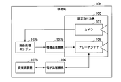
- FIG. 2 is a block diagram illustrating a configuration of a mobile station 10a according to the first embodiment of the present invention.
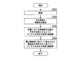
- 5 is a flowchart illustrating an operation of the mobile station 10a according to the first embodiment of the present invention.
- FIG. 9 is a block diagram illustrating a configuration of a mobile station 10b according to a second embodiment of the present invention. 9 is a flowchart illustrating an operation of the mobile station 10b according to the second embodiment of the present invention.
- FIG. 14 is a block diagram illustrating a configuration of a mobile station 10c according to a modification of the second embodiment of the present invention. It is a block diagram showing the composition of mobile station control system 1 concerning a 3rd embodiment of the present invention.
- FIG. 14 is a schematic diagram for explaining an example of a reception level recording process performed by a mobile station 10e according to a fourth embodiment of the present invention.
- FIG. 14 is a block diagram illustrating a configuration of a mobile station 10e according to a fourth embodiment of the present invention.
- 15 is a flowchart illustrating an operation of the mobile station 10e according to the fourth embodiment of the present invention.
- a mobile station in wireless communication between a mobile station and a mobile station (for example, a drone to a drone) will be described as an example.
- FIG. 1 is a block diagram showing a configuration of the mobile station 10a according to the first embodiment of the present invention.
- the mobile station 10a includes a camera 101, an image processing engine 102a, a machine tracking mechanism 103a, an antenna 104a, and a fixed mounting jig 100.
- the fixed mounting jig 100 is a member for fixing the camera 101 and the antenna 104a to the machine tracking mechanism 103a.
- the direction of the camera 101 (the direction of the optical axis of the lens) and the direction of the antenna 104a (the direction of the antenna) change according to the operation of the machine tracking mechanism 103a.
- the camera 101 and the antenna 104a are both set so that the direction of the optical axis (azimuth and elevation) of the lens of the camera 101 and the direction of irradiation of the beam of the electromagnetic wave emitted from the antenna 104a (that is, the directional direction) match. It is attached to the fixed attachment jig 100. Thus, the beam of the electromagnetic wave is emitted from the antenna 104a toward the position shown in the center of the image captured by the camera 101.
- the camera 101 and the antenna 104a are configured to be fixed by the fixed mounting jig 100, but the present invention is not limited to this.
- the camera 101 and the antenna 104a may not be fixed, and may be configured to be independently operable.
- the direction of the camera 101 and the direction of the antenna 104a can be independently changed. Therefore, for example, it is necessary to make the direction of the optical axis of the lens of the camera 101 coincide with the directional direction of the antenna 104 by using, for example, a calculation engine for correction separately.
- the camera 101 captures an image in a direction in which a mobile station (for example, a communication partner drone) on the opposite station side to be tracked exists.
- the camera 101 outputs image data indicating a captured image to the image processing engine 102a.
- the image processing engine 102a analyzes an image based on image data input from the camera 101.
- the image processing engine 102a identifies a mobile station on the opposite station side, which is shown in the image. Then, the image processing engine 102a specifies an image area indicating the mobile station on the opposite station side in the image based on the image data.
- the image processing engine 102a previously holds, for example, image data (master image data) indicating an image captured by the mobile station on the opposite station side, and stores the master image data and the image data input from the camera 101 in advance. May be specified to identify an image area indicating the mobile station on the opposite station side in the image.
- image data master image data
- image data input from the camera 101 May be specified to identify an image area indicating the mobile station on the opposite station side in the image.
- the image processing engine 102a performs the machine tracking so that the image area indicating the identified mobile station on the opposite station side is located at a predetermined position (for example, the center position) of the image based on the image data input from the camera 101.
- the mechanism 103a is operated.
- the mobile station on the opposite station side can be tracked by the antenna 104a.
- image processing is performed.
- the engine 102a controls the machine tracking mechanism 103a so that the imaging direction of the camera 101 is directed more upward.
- image processing engine 102a controls the machine tracking mechanism 104a so that the imaging direction of the camera 101 is directed more to the left.
- the mobile station 10a is configured to control the direction of the camera 101 by the mechanical tracking mechanism 103a, but the present invention is not limited to this.
- the mobile station 10a may be configured to control the direction of the camera 101 by a tracking mechanism that is electronically controlled (for example, a mechanism that performs tracking by electronic control using an array antenna).
- the camera 101 and the image processing engine 102a may be provided as external devices connected to the mobile station 10a instead of being provided in the housing of the mobile station 10a.
- FIG. 2 is a flowchart showing an operation of the mobile station 10a according to the first embodiment of the present invention.
- the camera 101 captures an image in the direction in which the mobile station on the side of the opposite station to be tracked exists (step S101).
- the camera 101 outputs image data indicating a captured image to the image processing engine 102a.
- the image processing engine 102a analyzes an image based on image data input from the camera 101.
- the image processing engine 102a identifies the mobile station on the side of the opposite station in the image (step S102). Then, the image processing engine 102a specifies an image area indicating the mobile station on the opposite station side in the image based on the image data.
- the image processing engine 102a determines that the position of the identified mobile station on the opposite station side (that is, the image area indicating the mobile station on the opposite station side) is a predetermined position of the image based on the image data input from the camera 101 (for example, , The center position) (step S103). As described above, the image processing engine 102a controls the directional direction of the antenna 104a by operating the machine tracking mechanism 103a. Thus, the process shown in the flowchart of FIG. 2 ends.
- the main difference between the configuration of the mobile station 10b according to the second embodiment described below and the configuration of the mobile station 10a according to the first embodiment described above is that the mobile station 10b according to the second embodiment is different from the mobile station 10b according to the second embodiment. This is further provided with an electronic tracking mechanism.
- the mobile station 10b first controls the directional direction of the antenna (the array antenna 105 described later) by the mechanical tracking mechanism in the same manner as the mobile station 10a according to the first embodiment described above. Coarse adjustment). Thereafter, the mobile station 10b further corrects (fine-adjusts) the control of the directional direction of the array antenna 105 by the electronic tracking mechanism (phase control mechanism).
- the fine adjustment of the control of the directivity of the antenna is performed by, for example, using the array antenna 105, information of a channel matrix calculated from power information or phase information obtained from electromagnetic waves received from a mobile station on the opposite station side. This is performed by calculating the arrival direction of the electromagnetic wave transmitted from the mobile station on the opposite station side.
- FIG. 3 is a block diagram illustrating a configuration of the mobile station 10b according to the second embodiment of the present invention.
- the mobile station 10b includes a camera 101, an image processing engine 102b, a mechanical tracking mechanism 103b, an array antenna 105, an electronic tracking mechanism 106, a modem 107b, and a fixed mounting jig 100. .
- the fixed mounting jig 100 is a member for fixing the camera 101 and the array antenna 105 to the machine tracking mechanism 103b. Thereby, the directivity of the camera 101 and the array antenna 105 changes according to the operation of the machine tracking mechanism 103b.
- the camera 101 and the array antenna 105 are both mounted on the fixed mounting jig 100 so that the direction of the optical axis of the lens of the camera 101 and the direction of the array antenna 105 match.
- the array antenna 105 emits a beam of electromagnetic waves toward a position shown in the center of the image captured by the camera 101.
- an error may occur between the direction (azimuth and elevation) of the optical axis of the lens of the camera 101 and the directional direction of the array antenna 105.
- the camera 101 captures an image in a direction in which a mobile station (for example, a communication partner drone) on the opposite station side to be tracked exists.
- the camera 101 outputs image data indicating a captured image to the image processing engine 102b.
- the image processing engine 102b analyzes an image based on the image data input from the camera 101.
- the image processing engine 102b identifies the mobile station on the opposite station side, which is shown in the image. Then, the image processing engine 102b specifies an image area indicating the mobile station on the opposite station side in the image based on the image data.
- the image processing engine 102b performs the machine tracking so that the image area indicating the identified mobile station on the opposite station side is located at a predetermined position (for example, a center position) of the image based on the image data input from the camera 101.
- the mechanism 103b is operated. Thereby, the coarse tracking of the tracking of the mobile station on the opposite station side by the array antenna 105 is performed by the mechanical tracking mechanism 103b.
- the array antenna 105 receives an electromagnetic wave radiated from a mobile station on the opposite station side.
- the electronic tracking mechanism 106 obtains, from the modem 107b, information on a propagation path matrix calculated from power information or phase information on the electromagnetic waves received by the array antenna 105, and the like.
- the electronic tracking mechanism 106 calculates the arrival direction of the electromagnetic wave transmitted from the mobile station on the opposite station side by using the acquired information.
- the electronic tracking mechanism 106 controls the array antenna 105 so that the directivity of the array antenna 105 matches the arrival direction of the electromagnetic wave transmitted from the mobile station on the opposite station side.
- the electronic tracking mechanism 106 finely adjusts the tracking of the mobile station on the opposite station side by the array antenna 105.
- FIG. 4 is a flowchart illustrating an operation of the mobile station 10b according to the second embodiment of the present invention.
- the camera 101 captures an image in the direction in which the mobile station on the opposite station side to be tracked exists (step S201).
- the camera 101 outputs image data indicating a captured image to the image processing engine 102b.
- the image processing engine 102b analyzes an image based on the image data input from the camera 101.
- the image processing engine 102b identifies the mobile station on the side of the opposite station, which is shown in the image (Step S202). Then, the image processing engine 102b specifies an image area indicating the mobile station on the opposite station side in the image based on the image data.
- the image processing engine 102b determines that the identified position of the mobile station on the opposite station side (that is, the image area indicating the mobile station on the opposite station side) is a predetermined position of the image based on the image data input from the camera 101 (for example, , The center position), a control for roughly adjusting the directivity of the array antenna 105 is performed (step S203). Note that the image processing engine 102b performs control for roughly adjusting the directional direction of the array antenna 105 by operating the machine tracking mechanism 103b.
- the electronic tracking mechanism 106 acquires information on a propagation path matrix calculated from power information or phase information related to the electromagnetic waves received by the array antenna 105.
- the electronic tracking mechanism 106 calculates the arrival direction of the electromagnetic wave transmitted from the mobile station on the opposite station side by using the acquired information. Then, the electronic tracking mechanism 106 performs control for finely adjusting the directivity of the array antenna 105 so as to match the calculated direction of arrival (step 204).
- the processing shown in the flowchart of FIG. 4 ends.
- the mobile station 10b according to the second embodiment described above has a configuration in which the pointing direction of the antenna (array antenna 105) is roughly adjusted by the mechanical tracking mechanism 103b, and then finely adjusted by the electronic tracking mechanism 106.
- the mobile station 10c according to a modification of the second embodiment described below not only the coarse adjustment of the directivity of the antenna but also the fine adjustment may be performed by the machine tracking mechanism 103b. .
- FIG. 5 is a block diagram illustrating a configuration of a mobile station 10c according to a modification of the second embodiment of the present invention.
- the mobile station 10c includes a camera 101, an image processing engine 102c, a machine tracking mechanism 103c, an antenna 104c, a modem 107c, and a fixed mounting jig 100. .
- the configuration of the mobile station 10b is the same as the configuration of the mobile station 10b according to the above-described second embodiment, and a description thereof will not be repeated.
- the antenna 104c receives an electromagnetic wave radiated from the mobile station on the opposite station side.
- the machine tracking mechanism 103c acquires information indicating the reception state of the electromagnetic wave received by the antenna 104c from the modem 107c. Then, the machine tracking mechanism 103c controls the pointing direction of the antenna 104c such that the value indicated by the acquired information indicating the reception state is the best.
- the mechanical tracking mechanism 103c acquires the value of the reception level of the electromagnetic wave received by the antenna 104c from the modem 107c, and controls the pointing direction of the antenna 104c so that the acquired value of the reception level becomes maximum.
- the mechanical tracking mechanism 103c performs not only coarse adjustment but also fine adjustment of the tracking of the mobile station on the opposite station side by the antenna 104c.
- the mobile station on the opposite station side is shown in a size larger than a certain size in the captured image and can be identified. Become. Therefore, when the distance between the own mobile station and the mobile station on the opposite station side is long, the camera is generally provided with a telephoto lens or the like. When a telephoto lens is used, the captured image is an enlarged image having a smaller imaging range. Therefore, the mobile station on the opposite station side tends to be out of the imaging range, and the case where the mobile station on the opposite station side is not shown in the image increases.
- the mobile station control system 1 uses an image generated by the mobile station on the opposite station side during the initial calibration or when the mobile station on the opposite station side is out of the imaging range.
- a configuration is provided in which the mobile station on the opposite station side can be tracked even when it is not imaged.
- FIG. 6 is a block diagram illustrating a configuration of the mobile station control system 1 according to the third embodiment of the present invention.
- the mobile station control system 1 includes a mobile station 10d and a location information management server 20.
- the mobile station 10d and the location information management server 20 are communicatively connected by radio.
- the mobile station 10d includes a camera 101, an image processing engine 102d, a machine tracking mechanism 103d, an antenna 104d, a position information acquisition unit 108, a position information transmission / reception unit 109, and coarse adjustment direction information.
- the processing unit 110 and the fixed mounting jig 100 are included.
- the position information acquisition unit 108 acquires position information indicating the position of the mobile station 10d (own mobile station).
- the position information acquisition unit 108 acquires position information indicating its own position using, for example, a GNSS such as a GPS or a gyro sensor. Then, the position information acquisition unit 108 transmits the position information indicating the own position to the position information management server 20 by wireless communication via the position information transmission / reception unit 109.
- a GNSS such as a GPS or a gyro sensor
- the coarse adjustment direction information processing unit 110 acquires relative positional relationship information from the positional information management server 20 via the positional information transmitting / receiving unit 109 by wireless communication.
- the relative positional relationship information is information indicating a relative positional relationship between a plurality of mobile stations, whose positional information is managed by the positional information management server 20.
- the coarse adjustment direction information processing unit 110 is configured to acquire, from the position information management server 20, relative positional relationship information indicating a relative positional relationship between the mobile station 10d of itself and the mobile station on the opposite station side. You may. Alternatively, the coarse adjustment direction information processing unit 110 transmits, from the position information management server 20, the relative position between its own mobile station 10d and all other mobile stations (position information is managed by the position information management server 20). A configuration may be adopted in which relative positional relationship information indicating a great positional relationship is acquired.
- the coarse adjustment direction information processing unit 110 calculates the direction (azimuth and elevation) of the mobile station on the opposite station side based on the acquired relative positional relationship information. Then, the coarse adjustment direction information processing unit 110 performs machine tracking such that the calculated direction of the mobile station on the opposite station side matches the direction of the optical axis of the lens of the camera 101 (and the directivity of the antenna 104d). The mechanism 103d is controlled. Thus, the coarse tracking of the tracking of the mobile station on the opposite station side by the antenna 104d is performed by the mechanical tracking mechanism 103d.
- the fixed mounting jig 100 is a member for fixing the camera 101 and the antenna 104d to the machine tracking mechanism 103d.
- the direction of the camera 101 and the directional direction of the antenna 104d change according to the operation of the machine tracking mechanism 103d.
- both the camera 101 and the antenna 104d are mounted on the fixed mounting jig 100 so that the direction of the optical axis (azimuth and elevation) of the lens of the camera 101 and the directional direction (azimuth and elevation) of the antenna 104d match. .
- the beam is emitted toward the position shown in the center of the image captured by the camera 101.
- the camera 101 captures an image in a direction in which a mobile station (for example, a communication partner drone) on the opposite station side to be tracked exists.
- the camera 101 outputs image data indicating a captured image to the image processing engine 102d.
- the image processing engine 102d analyzes an image based on the image data input from the camera 101.
- the image processing engine 102d identifies the mobile station on the side of the opposite station, which is shown in the image. Then, the image processing engine 102d specifies an image area indicating the mobile station on the opposite station side in the image based on the image data.
- the image processing engine 102d performs machine tracking such that the image area indicating the identified mobile station on the opposite station side is located at a predetermined position (for example, a center position) of an image based on image data input from the camera 101.
- the mechanism 103d is operated.
- the mobile station on the opposite station side can be tracked by the antenna 104d.
- the position information management server 20 includes a storage unit 200, a transmission / reception unit 201, and a relative positional relationship calculation processing unit 202.
- the storage unit 200 stores position information indicating the position of each mobile station, which is collected from each mobile station. Further, the storage unit 200 stores relative positional relationship information indicating a relative positional relationship between the two mobile stations, which is calculated based on the positional information indicating the position of each mobile station.
- the storage unit 200 is configured to include a storage medium such as a magnetic disk or a semiconductor memory.
- the transmission / reception unit 201 receives position information indicating the position of each mobile station, which is transmitted from the mobile station of each mobile station.
- the position information received by the transmitting / receiving unit 201 is stored in the storage unit 200.
- the relative positional relationship calculation processing unit 202 calculates the relative positional relationship between the mobile stations based on the position information indicating the position of each mobile station stored in the storage unit 200.
- the relative positional relationship calculation processing unit 202 generates relative positional relationship information indicating the relative positional relationship between the mobile stations. Then, the relative positional relationship calculation processing unit 202 causes the storage unit 200 to store the generated relative positional relationship information. Alternatively, the relative positional relationship calculation processing unit 202 transmits the generated relative positional relationship information to each mobile station via the transmitting / receiving unit 201.
- FIG. 7 is a flowchart illustrating an operation of the mobile station control system 1 according to the third embodiment of the present invention.
- the position information acquisition unit 108 of each mobile station 10d acquires position information indicating the position of its own mobile station 10d (own mobile station). (Steps S301-1 to S301-N).
- the position information acquisition unit 108 of each mobile station 10d wirelessly communicates the acquired position information indicating the own position via the position information transmission / reception unit 109. Respectively to the location information management server 20 (steps S302-1 to S302-1).
- the transmission / reception unit 201 of the location information management server 20 receives the location information indicating the location of each mobile station transmitted from each mobile station 10d (mobile station 1, mobile station 2, ..., mobile station N). (Step S303).
- the relative position relation calculation processing unit 202 of the position information management server 20 determines the position between the mobile stations based on the position information indicating the position of each mobile station 10d (mobile station 1, mobile station 2,..., Mobile station N). Are calculated (step S304).
- the relative positional relationship calculation processing unit 202 generates relative positional relationship information indicating the relative positional relationship between the mobile stations based on the above calculation result.
- the transmission / reception unit 201 of the location information management server 20 transmits the relative positional relationship information to each mobile station 10d (mobile station 1, mobile station 2, ..., mobile station N) (step S305).
- the position information transmission / reception section 109 of each mobile station 10d receives the relative position relationship information transmitted from the position information management server 20 (step S306-). 1 to N).
- the coarse adjustment direction information processing unit 110 of each mobile station 10d determines the direction (azimuth and direction) of the mobile station on the opposite station side based on the relative positional relationship information. Elevation). Then, the coarse adjustment direction information processing unit 110 controls the machine tracking mechanism 103d such that the calculated direction of the mobile station on the opposite station side matches the direction of the optical axis of the lens of the camera 101. As a result, coarse adjustment of the directivity direction of the antenna 104d is performed (steps S307-1 to S307-1).
- the camera 101 of each mobile station 10d performs imaging in the direction in which the mobile station on the opposite station side to be tracked exists (step S308-). 1 to N).
- the camera 101 outputs image data indicating a captured image to the image processing engine 102d.
- the image processing engine 102d of each mobile station 10d analyzes an image based on image data input from the camera 101.
- the image processing engine 102d identifies the mobile station on the opposite station side shown in the image (Steps S309-1 to S309-1). Then, the image processing engine 102d specifies an image area indicating the mobile station on the opposite station side in the image based on the image data.
- the image processing engine 102d of each mobile station 10d indicates the identified position of the mobile station on the opposite station side (that is, indicates the mobile station on the opposite station side).
- the directional direction of the antenna 104d is controlled so that the (image area) is at a predetermined position (for example, the center position) of the image based on the image data input from the camera 101 (steps S310-1 to N).
- a predetermined position for example, the center position
- the electronic tracking mechanism after performing image analysis to roughly adjust the pointing direction of the antenna by the mechanical tracking mechanism, the electronic tracking mechanism ( Even if the configuration is such that the directivity of the antenna is finely adjusted by the phase control mechanism), the fine adjustment of the directivity of the antenna may not be performed depending on the wireless communication system used for communication between mobile stations. This is because, depending on the wireless communication system, time-division processing such as the TDMA system is performed, so that it is not possible to make fine adjustments to the directivity of the antenna while the mobile station performs transmission processing.
- the mobile station 10e divides an imaging area of an image captured by the camera 101 into a plurality of blocks. Also, the mobile station 10e records the reception level of the reception signal received from the antenna 104e for each block in which the opposite station exists.
- FIG. 8 is a schematic diagram for explaining an example of a reception level recording process performed by the mobile station 10e according to the fourth embodiment of the present invention. As shown in FIG. 8, the value of the reception level is recorded for each block (for example, in FIG. 8, the value recorded in the range of “ ⁇ 9” to “0” is the reception level of each block. Value).
- the mobile station 10e After recording the reception level a predetermined number of times, the mobile station 10e sets the position indicated by the block having the largest average of the reception level values for each block as the position where the mobile station on the opposite station side exists. recognize. Note that the mobile station 10e may recognize the direction indicated by the block in which the maximum value is recorded among the stored reception level values as the position where the mobile station on the opposite station side exists. That is, any index value can be used as long as the index value indicates the reception state, not limited to the average value of the reception levels.
- the mobile station 10e controls the directional direction (azimuth and elevation) of the antenna 104e so that the directional direction of the antenna 104e matches the direction recognized above as the position where the mobile station on the opposite station exists.
- the mobile station 10e may be configured to record the reception level for each distance from its own mobile station to the mobile station on the opposite station side.
- the mobile station 10e is, for example, information indicating the relative positional relationship between the mobile stations used by the mobile station 10d according to the above-described third embodiment, or the mobile station on the opposite station side on the image. It is possible to calculate the distance from the own mobile station to the mobile station on the opposite station side from information obtained from the image such as the size.
- FIG. 9 is a block diagram illustrating a configuration of the mobile station 10e according to the fourth embodiment of the present invention.
- the mobile station 10e includes a camera 101, an image processing engine 102e, a machine tracking mechanism 103e, an antenna 104e, a fixed mounting jig 100, and a correction unit 111.
- the correction unit 111 includes an image division unit 112, a reception level recording unit 113, and a correction amount calculation unit 114.
- the fixed mounting jig 100 is a member for fixing the camera 101 and the antenna 104e to the machine tracking mechanism 103e. Thereby, the direction of the camera 101 and the directivity of the antenna 104e change according to the operation of the machine tracking mechanism 103e.
- both the camera 101 and the antenna 104e are mounted on the fixed mounting jig 100 so that the direction of the optical axis (azimuth and elevation) of the lens of the camera 101 and the directional direction (azimuth and elevation) of the antenna 104e match. .
- the beam is emitted toward the position shown in the center of the image captured by the camera 101.
- an error may occur between the direction of the optical axis (azimuth and elevation) of the lens of the camera 101 and the directional direction (azimuth and elevation) of the antenna 104e.
- the camera 101 captures an image in a direction in which a mobile station (for example, a communication partner drone) on the opposite station side to be tracked exists.
- the camera 101 outputs image data indicating a captured image to the image processing engine 102e.
- the image processing engine 102e analyzes an image based on image data input from the camera 101.
- the image processing engine 102e identifies the mobile station on the opposite station side, which is shown in the image. Then, the image processing engine 102e specifies an image area indicating the mobile station on the opposite station side in the image based on the image data.
- the image processing engine 102e performs the machine tracking so that the image area indicating the identified mobile station on the opposite station side is located at a predetermined position (for example, the center position) of the image based on the image data input from the camera 101.
- the mechanism 103e is operated. As a result, coarse adjustment of the directivity of the antenna 104e for tracking the mobile station on the opposite station side by the antenna 104e is performed.
- the image processing engine 102e outputs, to the image dividing unit 112, the image data input from the camera 101 and the information indicating the image area in which the mobile station on the opposite station side is captured in the image.
- the image division unit 112 divides an image based on the image data input from the image processing engine 102e into a plurality of blocks, for example, as shown in the schematic diagram of FIG.
- the image division unit 112 outputs, to the reception level recording unit 113, the image data input from the image processing engine 102e, information on the divided blocks, and information indicating an image area in which the mobile station on the opposite station side is captured in the image. I do.
- the reception level recording unit 113 determines whether the opposite station exists based on the image data, the block information, and the information indicating the image area where the mobile station on the opposite station side is captured in the image. Identify the block that is Then, reception level recording section 113 records information (for example, the value of the reception level) indicating the reception state of the reception signal received from antenna 104e for each block in which the opposite station exists.
- the reception level recording unit 113 stores information (for example, the value of the reception level) indicating the reception state of the reception signal for each block in which the opposite station exists, Output to the correction amount calculation unit 114.
- the correction amount calculation unit 114 calculates a value based on the information indicating the reception state of the reception signal based on the information input from the reception level recording unit 113 and indicating the reception state of the reception signal for each block in which the opposite station exists. Is recognized as the position where the mobile station on the opposite station side exists.
- the correction amount calculation unit 114 indicates the block having the largest average of the reception level values based on the reception level value for each block in which the opposite station exists, which is input from the reception level recording unit 113.
- the direction is recognized as the position where the mobile station on the opposite station side exists.
- the mobile station 10e may be configured to recognize the direction indicated by the block in which the maximum value is recorded among the stored reception level values as the position where the mobile station on the opposite station side exists.
- the correction amount calculation unit 114 controls the machine tracking mechanism 103e so that the directional direction of the antenna 104e matches the direction recognized as the position where the mobile station on the opposite station side exists in the above, and thereby the directional direction of the antenna 104e. (Azimuth and elevation).
- FIG. 10 is a flowchart illustrating an operation of the mobile station 10e according to the fourth embodiment of the present invention.
- the camera 101 captures an image in a direction in which the mobile station on the side of the opposite station to be tracked exists (step S401).
- the camera 101 outputs image data indicating a captured image to the image processing engine 102e.
- the image processing engine 102e analyzes an image based on image data input from the camera 101.
- the image processing engine 102e identifies a mobile station on the side of the opposite station in the image (step S402). Then, the image processing engine 102e specifies an image area indicating the mobile station on the opposite station side in the image based on the image data.
- the image processing engine 102e determines that the position of the identified mobile station on the opposite station side (that is, the image area indicating the mobile station on the opposite station side) is a predetermined position of the image based on the image data input from the camera 101 (for example, , The center position) is roughly controlled (step S403). Note that, as described above, the image processing engine 102e performs control for roughly adjusting the directivity of the antenna 104e by operating the machine tracking mechanism 103a.
- the image dividing unit 112 divides an image into a plurality of blocks.
- the image dividing unit 112 outputs to the reception level recording unit 113 the image data, information on the divided blocks, and information indicating the image area where the mobile station on the opposite station side is shown in the image.
- the reception level recording unit 113 records, for example, the reception level of the reception signal received from the antenna 104e for each block where the mobile station on the opposite station side exists in the image (step S404).
- the reception level recording unit 113 outputs to the correction amount calculation unit 114 information indicating the reception level of each block in which the opposite station exists. If the reception level has not been recorded a predetermined number of times (No in step S405), the correction amount calculation unit 114 controls the mechanical tracking mechanism 103e to slightly move the pointing directions of the camera 101 and the antenna 104e (step S405). S406), and returns to the process of step S404.
- step S405 If the reception level has been recorded a predetermined number of times (Yes in step S405), the correction amount calculation unit 114 determines the direction of the antenna in the direction corresponding to the block in which the average value of the recorded reception levels is the maximum.
- the machine tracking mechanism 103e is controlled so as to finely adjust (step S407).
- the mobile station 10a (first mobile object) according to the first embodiment of the present invention includes the camera 101 and the antenna 104a.
- the mobile station 10a receives the image of the camera 101 that operates so that the direction of the optical axis of the camera 101 and the directional direction of the antenna 104a are interlocked.
- An image processing engine 102a (identifying unit) for identifying a moving object is provided.
- the mobile station 10a includes a mechanical tracking mechanism 103a (antenna control unit) that controls the directivity of the antenna 104a so that the position of the identified mobile station on the opposite station side in the captured image becomes a predetermined position.
- the mobile station 10b matches the direction of the mobile station on the opposite station calculated based on the information on the electromagnetic waves received from the mobile station on the opposite station.
- An electronic tracking mechanism 106 (correction unit) for controlling the directional direction of the array antenna 105 is further provided so as to perform the control.
- the mobile station control system 1 includes the mobile station 10d (first mobile unit) including the camera 101 and the antenna 104d and the location information management server 20 ( Server).
- the above-mentioned mobile station 10d is an image for identifying a mobile station on the opposite station side by image recognition from an image taken by the camera 101 operating so that the direction of the optical axis of the camera 101 and the direction of the antenna 104d are linked. It includes a processing engine 102d.
- the mobile station control system 1 includes a machine tracking mechanism 103d that controls the pointing direction of the antenna such that the position of the identified mobile station on the opposite station side in the captured image becomes a predetermined position.
- the mobile station control system 1 transmits position information (first position information) indicating the position of its own mobile station to the server, and compares the position of its own mobile station with the position of the mobile station on the opposite station side.
- a positional information transmitting / receiving unit 109 (a positional information transmitting unit and a relative positional relationship information receiving unit) that receives relative positional relationship information indicating a positional relationship from the positional information management server 20.
- the position information management server 20 transmits and receives the position information indicating the position of its own mobile station and the position information (second position information) indicating the position of the mobile station on the opposite station side (second position information). Acquisition unit).
- the position information management server 20 is a relative position relation calculation processing unit that generates relative position relation information based on position information indicating the position of its own mobile station and position information indicating the position of the mobile station on the opposite station side. 202.
- the transmitting / receiving unit 201 (relative positional relationship information transmitting unit) transmits the relative positional relationship information calculated by the relative positional relationship calculation processing unit 202 to the mobile station 10d.
- the machine tracking mechanism 103d controls the pointing direction of the antenna 104d so as to match the direction of the mobile station on the opposite station side calculated based on the relative positional relationship information received by the position information transmitting / receiving unit 109.
- the mobile station 10e includes the camera 101 and the antenna 104e. Further, the mobile station 10e identifies an opposite-station-side mobile station by image recognition from an image captured by the camera 101 that operates so that the direction of the optical axis of the camera 101 and the direction of the antenna 104e are linked.
- the processing engine 102e is provided. Further, the mobile station 10e includes a mechanical tracking mechanism 103e that controls the pointing direction of the antenna 104e such that the position of the identified mobile station on the opposite station side in the captured image is a predetermined position.
- the mobile station 10e calculates an index value indicating the reception state for each of a plurality of regions forming the captured image based on the reception state of the electromagnetic wave transmitted from the mobile station on the opposite station side. Reception state calculation unit). Further, the machine tracking mechanism 103e controls the directional direction of the antenna 104e so as to match the direction based on the region having the highest index value.
- the mobile station (mobile station 10a, mobile station 10b, mobile station 10c, mobile station 10d, and mobile station 10e) and the mobile station control system 1 according to each of the above-described embodiments perform, for example, time division processing.
- accurate tracking can be performed even when communication is performed using a wireless communication method in which there is a period during which a received signal cannot be obtained.
- the mobile stations (mobile station 10a, mobile station 10b, mobile station 10c, mobile station 10d and mobile station 10e) and a part of the mobile station control system 1 in the above embodiment may be realized by a computer.
- a program for realizing this function may be recorded on a computer-readable recording medium, and the program recorded on this recording medium may be read and executed by a computer system.
- the “computer system” includes an OS and hardware such as peripheral devices.
- the “computer-readable recording medium” refers to a portable medium such as a flexible disk, a magneto-optical disk, a ROM, and a CD-ROM, and a storage device such as a hard disk built in a computer system.
- a “computer-readable recording medium” refers to a communication line for transmitting a program via a network such as the Internet or a communication line such as a telephone line, which dynamically holds the program for a short time.
- a program may include a program that holds a program for a certain period of time, such as a volatile memory in a computer system serving as a server or a client in that case.
- the program may be for realizing a part of the functions described above, or may be a program that can realize the functions described above in combination with a program already recorded in a computer system, It may be realized by using a programmable logic device such as an FPGA (Field Programmable Gate Array).
- FPGA Field Programmable Gate Array
- Image processing Engine 103a, 103b, 103c, 103d, 103e: mechanical tracking mechanism; 104a, 104c, 104d, 104e: antenna, 105: array antenna, 106: electronic tracking mechanism, 107b, 107c: modem, 108: position information acquisition unit 109: Position information transmitting / receiving unit 110: Coarse adjustment direction information processing unit 111: Correcting unit 112: Image dividing unit 113: Received level recording unit 114: Correction amount calculating unit 200: Storage unit 201: Transmission Unit, 202: relative positional relationship calculation processing unit
Landscapes
- Engineering & Computer Science (AREA)
- Physics & Mathematics (AREA)
- General Physics & Mathematics (AREA)
- Signal Processing (AREA)
- Theoretical Computer Science (AREA)
- Computer Networks & Wireless Communication (AREA)
- Computer Vision & Pattern Recognition (AREA)
- Multimedia (AREA)
- Electromagnetism (AREA)
- Remote Sensing (AREA)
- Radar, Positioning & Navigation (AREA)
- Position Fixing By Use Of Radio Waves (AREA)
- Accessories Of Cameras (AREA)
- Radar Systems Or Details Thereof (AREA)
- Telephonic Communication Services (AREA)
- Image Analysis (AREA)
- Details Of Cameras Including Film Mechanisms (AREA)
- Mobile Radio Communication Systems (AREA)
Abstract
カメラ及びアンテナを備えた第1の移動体に搭載された制御装置は、前記カメラの光軸の向きと前記アンテナの指向方向とが連動するように動作するカメラと、前記カメラによって撮像された撮像画像から画像認識によって第2の移動体を識別する識別部と、識別された前記第2の移動体の前記撮像画像における位置が所定の位置となるように、前記アンテナの指向方向を制御するアンテナ制御部と、を備える。
Description
本発明は、制御装置、制御システム及び制御方法に関する。
昨今、無線通信において、固定局対固定局の間の通信、移動局対基地局の間の通信のほか、移動局を中継局とする移動局対基地局の間の通信、及び、移動局同士の間の通信(M2M;Machine-to-Machine)が注目されている。上記の通信においては、例えばWi-Fi(ワイファイ)に代表されるIEEE(The Institute of Electrical and Electronics Engineers, Inc.)802.11規格に基づく無線通信方式、及び、例えばLTE(登録商標)(Long Term Evolution)等のcellular(セルラー)方式の無線通信方式が一般に用いられている。
しかしながら、ある程度広い範囲を移動しつつ総スループット数が100Mbps以上となるような大容量伝送を行う場合においては、上記の無線通信方式は適当ではない場合がある。なぜならば、無線局間の距離が遠くなるほど無線局において受信される電力が減衰してしまうため、所望のC/N比(Carrier to Noise Ratio;搬送波対雑音比)を満たさなくなるためである。
所望のC/N比を満たしつつ、より高速なデータ通信を行うためには、より高利得のアンテナが必要になる。高利得アンテナは、一般に大開口径を有するアンテナであるため、メインビームの幅が狭くなる。これにより、移動局が移動することによって、移動局の位置がアンテナの指向方向から外れてしまい易くなる。そのため、移動局を追尾するための追尾機構が必要になる。
従来、このような追尾機構は、例えば高利得アンテナを必要とする、衛星対移動局(地球局)の間の通信において利用されることが多かった。衛星通信システムにおいては、衛星と地球局とは一対多の通信になる。そのため、衛星は姿勢制御によって地球表面の方向へアンテナを向けている。これにより、衛星側には、上記のような追尾機構は用いられない。
これに対して、それぞれの地球局は、衛星の方向へアンテナを向ける必要がある。そのため、地球局は、例えばGPS(Global Positioning System)やGLONASS(Global Navigation Satellite System)等のGNSS(Global Navigation Satellite System;全球測位衛星システム)又はジャイロセンサ等の各種センサを用いて自己位置を検出する。そして、地球局は、自己位置と予めデータベース等に登録されている衛星の位置とに基づいて算出される衛生の方向へメインビームを向けている。地球局は、例えば、コニカルスキャン等を用いた機械的追尾の方法によって(例えば、非特許文献1及び非特許文献2を参照)、又は、アレーアンテナ等を用いた電子的追尾の方法によって(例えば、非特許文献3を参照)、衛星を捕捉している。
このように、衛星通信システムでは、地球局側にのみ、追尾機構があればよい。これに対し、移動局同士の間の通信(例えばドローン(drone)対ドローンの間の通信等)では、双方の移動局がお互いの相対的な位置関係を把握する必要がある。そのため、従来技術では、例えば双方の移動局に追尾機構を設ける等、追尾機構に対する要求精度を高めるための何らかの構成を備える必要がある。
吉田富彦 他,「高精度衛星自動追尾アンテナの構成と制御方式の検討」,信学技報 A・P2003-4 SAT2003-4,pp.19-24,社団法人 電子情報通信学会,2003年
桧垣潤一 他,「船舶用ブロードバンドアンテナにおける防振機構系と追尾制御系の設計手法について」,電子情報通信学会論文誌 B Vol.J91-B No.12,pp.1578-1586,社団法人 電子情報通信学会,2008年
菊間信良,「アダプティブアンテナ技術」,pp.122-124,株式会社オーム社,2003年
ところで、例えば、IEEE802.11規格に基づく無線通信方式等の無線通信方式においては、TDMA(Time Division Multiple Access;時分割多元接続)方式のような時分割処理が行われる。そのため、上述したような、通信信号の受信状態から追尾を行うコニカルスキャン又はアレーアンテナを用いるだけでは、受信信号が得られなくなる期間が存在し、タイムラグが生じることがある。そのため従来技術においては、受信信号が得られなくなる期間が存在する無線通信方式を用いて通信が行われる場合、正確な追尾を行うことが難しいという課題があった。
上記事情に鑑み、本発明は、受信信号が得られなくなる期間が存在する無線通信方式を用いて通信が行われる場合であっても、正確な追尾を行うことができる技術の提供を目的としている。
本発明の一態様は、カメラ及びアンテナを備えた第1の移動体に搭載された制御装置であって、前記カメラの光軸の向きと前記アンテナの指向方向とが連動するように動作する前記カメラによって撮像された撮像画像から画像認識によって第2の移動体を識別する識別部と、識別された前記第2の移動体の前記撮像画像における位置が所定の位置となるように、前記アンテナの指向方向を制御するアンテナ制御部と、を備える制御装置である。
また、本発明の一態様は、上記の制御装置であって、前記第2の移動体から受信した電磁波に関する情報に基づいて前記第2の移動体の方向を算出し、算出された前記第2の移動体の方向と一致させるように、前記アンテナの指向方向を制御する補正部をさらに備える。
また、本発明の一態様は、上記の制御装置であって、前記第1の移動体の位置を示す第1位置情報をサーバへ送信する位置情報送信部と、前記第1の移動体の位置と前記第2の移動体の位置との相対的な位置関係を示す相対位置関係情報を前記サーバから受信する相対位置関係情報受信部と、をさらに備え、前記アンテナ制御部は、前記相対位置関係情報受信部によって受信された前記相対位置関係情報に基づいて算出される前記第2の移動体の方向と一致させるように、前記アンテナの指向方向を制御する。
また、本発明の一態様は、上記の制御装置であって、前記アンテナ制御部は、前記撮像画像を構成する複数の領域のうち、受信状態を示す指標値が最も高い領域に基づく方向と一致させるように、前記アンテナの指向方向を制御する。
また、本発明の一態様は、カメラ及びアンテナを備えた第1の移動体に搭載された制御装置とサーバとを有する制御システムであって、前記制御装置は、前記カメラの光軸の向きと前記アンテナの指向方向とが連動するように動作する前記カメラによって撮像された撮像画像から画像認識によって第2の移動体を識別する識別部と、識別された前記第2の移動体の前記撮像画像における位置が所定の位置となるように、前記アンテナの指向方向を制御するアンテナ制御部と、前記第1の移動体の位置を示す第1位置情報をサーバへ送信する位置情報送信部と、前記第1の移動体の位置と前記第2の移動体の位置との相対的な位置関係を示す相対位置関係情報を前記サーバから受信する相対位置関係情報受信部と、備え、前記サーバは、前記第1位置情報と、前記第2の移動体の位置を示す第2位置情報と、を取得する位置情報取得部と、前記第1位置情報と前記第2位置情報とに基づいて前記相対位置関係情報を生成する相対位置関係計算処理部と、前記相対位置関係計算処理部によって算出された前記相対位置関係情報を前記制御装置へ送信する相対位置関係情報送信部と、を備え、前記アンテナ制御部は、前記相対位置関係情報受信部によって受信された前記相対位置関係情報に基づいて算出される前記第2の移動体の方向と一致させるように、前記アンテナの指向方向を制御する制御システムである。
また、本発明の一態様は、カメラ及びアンテナを備えた第1の移動体に搭載された制御システムであって、前記カメラの光軸の向きと前記アンテナの指向方向とが連動するように動作する前記カメラによって撮像された撮像画像から画像認識によって第2の移動体を識別する識別部と、識別された前記第2の移動体の前記撮像画像における位置が所定の位置となるように、前記アンテナの指向方向を制御するアンテナ制御部と、前記第2の移動体から送出された電磁波の受信状態に基づいて、前記撮像画像を構成する複数の領域ごとに受信状態を示す指標値を算出する受信状態算出部と、を備え、前記アンテナ制御部は、前記指標値が最も高い領域に基づく方向と一致させるように、前記アンテナの指向方向を制御する制御システムである。
また、本発明の一態様は、カメラ及びアンテナを備えた第1の移動体に搭載されたコンピュータによる制御方法であって、前記カメラの光軸の向きと前記アンテナの指向方向とが連動するように動作するカメラの撮像画像から画像認識によって第2の移動体を識別する識別ステップと、識別された前記第2の移動体の前記撮像画像における位置が所定の位置となるように、前記アンテナの指向方向を制御する第1アンテナ制御ステップと、前記第1の移動体の位置を示す第1位置情報と、前記第2の移動体の位置を示す第2位置情報と、を取得する位置情報取得ステップと、前記第1位置情報と前記第2位置情報とに基づいて、前記第1の移動体と前記第2の移動体との相対的な位置関係を示す相対位置関係情報を生成する相対位置関係情報生成ステップと、前記相対位置関係情報に基づいて算出される前記第2の移動体の方向と一致させるように、前記第1の移動体の前記アンテナの指向方向を制御する第2アンテナ制御ステップと、を有する制御方法である。
また、本発明の一態様は、カメラ及びアンテナを備えた第1の移動体に搭載されたコンピュータによる制御方法であって、前記カメラの光軸の向きと前記アンテナの指向方向とが前記アンテナと連動して動作するカメラの撮像画像から画像認識によって第2の移動体を識別する識別ステップと、識別された前記第2の移動体の前記撮像画像における位置が所定の位置となるように、前記アンテナの指向方向を制御する第1アンテナ制御ステップと、前記第2の移動体から送出された電磁波の受信状態に基づいて、前記撮像画像を構成する複数の領域ごとに受信状態を示す指標値を算出する受信状態算出ステップと、前記指標値が最も高い領域に基づく方向と一致させるように、前記第1の移動体の前記アンテナの指向方向を制御する第2アンテナ制御ステップと、を有する制御方法である。
本発明により、受信信号が得られなくなる期間が存在する無線通信方式を用いて通信が行われる場合であっても、正確な追尾を行うことができる。
以下、本発明の実施形態について説明する。
以下に説明する各実施形態では、一例として、移動局対移動局(例えば、ドローン対ドローン)の間の無線通信における移動局について説明する。
以下に説明する各実施形態では、一例として、移動局対移動局(例えば、ドローン対ドローン)の間の無線通信における移動局について説明する。
<第1の実施形態>
以下、本発明の第1の実施形態に係る移動局10aについて、図面を参照しながら説明する。
以下、本発明の第1の実施形態に係る移動局10aについて、図面を参照しながら説明する。
[移動局の構成]
以下、移動局10aの構成について説明する。
図1は、本発明の第1の実施形態に係る移動局10aの構成を示すブロック図である。
図1に示すように、移動局10aは、カメラ101と、画像処理エンジン102aと、機械追尾機構103aと、アンテナ104aと、固定取付治具100と、を含んで構成される。
以下、移動局10aの構成について説明する。
図1は、本発明の第1の実施形態に係る移動局10aの構成を示すブロック図である。
図1に示すように、移動局10aは、カメラ101と、画像処理エンジン102aと、機械追尾機構103aと、アンテナ104aと、固定取付治具100と、を含んで構成される。
固定取付治具100は、機械追尾機構103aに対してカメラ101及びアンテナ104aを固定するための部材である。これにより、機械追尾機構103aの動作に応じて、カメラ101の向き(レンズの光軸の方向)及びアンテナ104aの向き(アンテナの指向方向)が変化する。
また、カメラ101のレンズの光軸の方向(方位及び仰角)と、アンテナ104aから照射される電磁波のビームの照射方向(すなわち、指向方向)とが一致するように、カメラ101及びアンテナ104aは共に固定取付治具100に取り付けられる。これにより、カメラ101によって撮像された画像の中央に写っている位置に向けて、アンテナ104aから電磁波のビームが照射されることになる。
なお、上述したように、本実施形態においては、カメラ101及びアンテナ104aは、固定取付治具100よって固定される構成としたが、これに限られるものではない。例えば、カメラ101及びアンテナ104aが固定されておらず、それぞれ独立して動作可能に構成されていても構わない。但し、この場合においては、カメラ101の向きとアンテナ104aの向きとがそれぞれ独立して変化することが可能になる。そのため、例えば、別途補正用の計算エンジン等を用いることによって、カメラ101のレンズの光軸の方向と、アンテナ104の指向方向とを一致させるようにする必要がある。
カメラ101は、追尾対象である対向局側の移動局(例えば、通信相手のドローン)が存在する方向に向けて撮像を行う。カメラ101は、撮像された画像を示す画像データを画像処理エンジン102aへ出力する。
画像処理エンジン102aは、カメラ101から入力された画像データに基づく画像を解析する。画像処理エンジン102aは、画像に写っている対向局側の移動局を識別する。そして、画像処理エンジン102aは、画像データに基づく画像内における、対向局側の移動局を示す画像領域を特定する。
なお、画像処理エンジン102aは、例えば、対向局側の移動局が撮像された画像を示す画像データ(マスター画像データ)を予め保持しており、マスター画像データとカメラ101から入力された画像データとを照合することによって、画像内における対向局側の移動局を示す画像領域を特定するようにしてもよい。
画像処理エンジン102aは、識別された対向局側の移動局を示す画像領域が、カメラ101から入力される画像データに基づく画像の所定の位置(例えば、中央の位置)となるように、機械追尾機構103aを動作させる。これにより、アンテナ104aによる対向局側の移動局の追尾が可能になる。
例えば、カメラ101から入力される画像データに基づく画像において、対向局側の移動局を示す画像領域が所定の位置(例えば、中央の位置)よりも上側に位置している場合には、画像処理エンジン102aは、カメラ101の撮像方向をより上側へ向けるように、機械追尾機構103aを制御する。また、例えば、カメラ101から入力される画像データに基づく画像において、対向局側の移動局を示す画像領域が所定の位置(例えば、中央の位置)よりも左側に位置している場合には、画像処理エンジン102aは、カメラ101の撮像方向をより左側へ向けるように、機械追尾機構104aを制御する。
なお、上述したように、本実施形態においては、移動局10aは、機械追尾機構103aによってカメラ101の向きを制御する構成としたが、これに限られるものではない。
例えば、移動局10aは、電子的に制御される追尾機構(例えば、アレーアンテナを用いて電子制御により追尾を行う機構等)によってカメラ101の向きを制御するような構成であっても構わない。
例えば、移動局10aは、電子的に制御される追尾機構(例えば、アレーアンテナを用いて電子制御により追尾を行う機構等)によってカメラ101の向きを制御するような構成であっても構わない。
なお、カメラ101及び画像処理エンジン102aは、移動局10aの筐体の中に備えられる代わりに、移動局10aに接続する外部の装置として備えられる構成であっても構わない。
[移動局の動作]
以下、移動局10aの動作の一例について説明する。
図2は、本発明の第1の実施形態に係る移動局10aの動作を示すフローチャートである。
以下、移動局10aの動作の一例について説明する。
図2は、本発明の第1の実施形態に係る移動局10aの動作を示すフローチャートである。
カメラ101は、追尾対象である対向局側の移動局が存在する方向に向けて撮像を行う(ステップS101)。カメラ101は、撮像された画像を示す画像データを画像処理エンジン102aへ出力する。
画像処理エンジン102aは、カメラ101から入力された画像データに基づく画像を解析する。画像処理エンジン102aは、画像に写っている対向局側の移動局を識別する(ステップS102)。そして、画像処理エンジン102aは、画像データに基づく画像内における、対向局側の移動局を示す画像領域を特定する。
画像処理エンジン102aは、識別された対向局側の移動局の位置(すなわち、対向局側の移動局を示す画像領域)が、カメラ101から入力される画像データに基づく画像の所定の位置(例えば、中央の位置)となるように、アンテナ104aの指向方向を制御する(ステップS103)。
なお、上述したように、画像処理エンジン102aは、機械追尾機構103aを動作させることによってアンテナ104aの指向方向を制御する。
以上で、図2のフローチャートが示す処理が終了する。
なお、上述したように、画像処理エンジン102aは、機械追尾機構103aを動作させることによってアンテナ104aの指向方向を制御する。
以上で、図2のフローチャートが示す処理が終了する。
<第2の実施形態>
以下、本発明の第2の実施形態に係る移動局10bについて、図面を参照しながら説明する。
以下、本発明の第2の実施形態に係る移動局10bについて、図面を参照しながら説明する。
以下に説明する第2の実施形態に係る移動局10bの構成と上述した第1の実施形態に係る移動局10aの構成との主な差異点は、第2の実施形態に係る移動局10bが電子追尾機構をさらに備えている点である。
一般的には、カメラのレンズの光軸の方向と、アンテナの指向方向とを、厳密に一致させることは困難である。そのため、カメラによって撮像された画像における対向局側の移動局の位置に基づいて対向局側の移動局の追尾を行った場合、対向局側の移動局の方向とアンテナの指向方向との間には実際の若干の誤差が生じることがある。また、機械追尾機構の制御分解能による制約によっても、若干の誤差が生じることがある。
そこで、第2の実施形態に係る移動局10bは、まず、上述した第1の実施形態に係る移動局10aと同様に機械追尾機構によって、アンテナ(後述するアレーアンテナ105)の指向方向の制御(粗調整)を行う。その後、移動局10bは、さらに電子追尾機構(位相制御機構)によって、アレーアンテナ105の指向方向の制御の補正(微調整)を行う。
ここで、アンテナの指向方向の制御の微調整は、例えば、アレーアンテナ105を用いて、対向局側の移動局から受信した電磁波から得られる電力情報又は位相情報から算出される伝搬路行列の情報等から、対向局側の移動局から送信された電磁波の到来方向を算出することによって行われる。
[移動局の構成]
以下、移動局10bの構成について説明する。
図3は、本発明の第2の実施形態に係る移動局10bの構成を示すブロック図である。
図3に示すように、移動局10bは、カメラ101と、画像処理エンジン102bと、機械追尾機構103bと、アレーアンテナ105と、電子追尾機構106と、変復調装置107bと、固定取付治具100と、を含んで構成される。
以下、移動局10bの構成について説明する。
図3は、本発明の第2の実施形態に係る移動局10bの構成を示すブロック図である。
図3に示すように、移動局10bは、カメラ101と、画像処理エンジン102bと、機械追尾機構103bと、アレーアンテナ105と、電子追尾機構106と、変復調装置107bと、固定取付治具100と、を含んで構成される。
固定取付治具100は、機械追尾機構103bに対してカメラ101及びアレーアンテナ105を固定するための部材である。これにより、機械追尾機構103bの動作に応じて、カメラ101及びアレーアンテナ105の指向方向が変化する。
また、カメラ101のレンズの光軸の方向と、アレーアンテナ105の指向方向とが一致するように、カメラ101及びアレーアンテナ105は共に固定取付治具100に取り付けられる。これにより、カメラ101によって撮像された画像の中央に写っている位置に向けて、アレーアンテナ105から電磁波のビームが照射されることになる。但し、上述したように、カメラ101のレンズの光軸の方向(方位及び仰角)と、アレーアンテナ105の指向方向とには、誤差が生じることがある。
カメラ101は、追尾対象である対向局側の移動局(例えば、通信相手のドローン)が存在する方向に向けて撮像を行う。カメラ101は、撮像された画像を示す画像データを画像処理エンジン102bへ出力する。
画像処理エンジン102bは、カメラ101から入力された画像データに基づく画像を解析する。画像処理エンジン102bは、画像に写っている対向局側の移動局を識別する。そして、画像処理エンジン102bは、画像データに基づく画像内における、対向局側の移動局を示す画像領域を特定する。
画像処理エンジン102bは、識別された対向局側の移動局を示す画像領域が、カメラ101から入力される画像データに基づく画像の所定の位置(例えば、中央の位置)となるように、機械追尾機構103bを動作させる。これにより、機械追尾機構103bによって、アレーアンテナ105による対向局側の移動局の追尾の粗調整が行われる。
アレーアンテナ105は、対向局側の移動局から放射された電磁波を受信する。
電子追尾機構106は、変復調装置107bから、アレーアンテナ105によって受信された電磁波に関する電力情報又は位相情報から算出される伝搬路行列の情報等を取得する。電子追尾機構106は、取得したこれらの情報を用いて、対向局側の移動局から送信された電磁波の到来方向を算出する。
電子追尾機構106は、変復調装置107bから、アレーアンテナ105によって受信された電磁波に関する電力情報又は位相情報から算出される伝搬路行列の情報等を取得する。電子追尾機構106は、取得したこれらの情報を用いて、対向局側の移動局から送信された電磁波の到来方向を算出する。
そして、電子追尾機構106は、アレーアンテナ105の指向方向を、対向局側の移動局から送信された電磁波の到来方向に一致させるようにアレーアンテナ105を制御する。これにより、電子追尾機構106によって、アレーアンテナ105による対向局側の移動局の追尾の微調整が行われる。
[移動局の動作]
以下、移動局10bの動作の一例について説明する。
図4は、本発明の第2の実施形態に係る移動局10bの動作を示すフローチャートである。
以下、移動局10bの動作の一例について説明する。
図4は、本発明の第2の実施形態に係る移動局10bの動作を示すフローチャートである。
カメラ101は、追尾対象である対向局側の移動局が存在する方向に向けて撮像を行う(ステップS201)。カメラ101は、撮像された画像を示す画像データを画像処理エンジン102bへ出力する。
画像処理エンジン102bは、カメラ101から入力された画像データに基づく画像を解析する。画像処理エンジン102bは、画像に写っている対向局側の移動局を識別する(ステップS202)。そして、画像処理エンジン102bは、画像データに基づく画像内における、対向局側の移動局を示す画像領域を特定する。
画像処理エンジン102bは、識別された対向局側の移動局の位置(すなわち、対向局側の移動局を示す画像領域)が、カメラ101から入力される画像データに基づく画像の所定の位置(例えば、中央の位置)となるように、アレーアンテナ105の指向方向を粗調整するための制御を行う(ステップS203)。
なお、画像処理エンジン102bは、機械追尾機構103bを動作させることによってアレーアンテナ105の指向方向を粗調整するための制御を行う。
なお、画像処理エンジン102bは、機械追尾機構103bを動作させることによってアレーアンテナ105の指向方向を粗調整するための制御を行う。
電子追尾機構106は、アレーアンテナ105によって受信された電磁波に関する電力情報又は位相情報をから算出される伝搬路行列の情報等を取得する。電子追尾機構106は、取得したこれらの情報を用いて、対向局側の移動局から送信された電磁波の到来方向を算出する。そして、電子追尾機構106は、算出された到来方向に一致させるように、アレーアンテナ105の指向方向を微調整するための制御を行う(ステップ204)。
以上で、図4のフローチャートが示す処理が終了する。
以上で、図4のフローチャートが示す処理が終了する。
<第2の実施形態の変形例>
以下、本発明の第2の実施形態の変形例に係る移動局10cについて、図面を参照しながら説明する。
以下、本発明の第2の実施形態の変形例に係る移動局10cについて、図面を参照しながら説明する。
上述した第2の実施形態に係る移動局10bは、アンテナ(アレーアンテナ105)の指向方向を、機械追尾機構103bによって粗調整した後、電子追尾機構106によって微調整する構成であった。しかしながら、以下に説明する第2の実施形態の変形例に係る移動局10cのように、アンテナの指向方向の粗調整だけでなく、微調整についても、機械追尾機構103bによって行う構成にしてもよい。
[移動局の構成]
以下、移動局10cの構成について説明する。
図5は、本発明の第2の実施形態の変形例に係る移動局10cの構成を示すブロック図である。図4に示すように、移動局10cは、カメラ101と、画像処理エンジン102cと、機械追尾機構103cと、アンテナ104cと、変復調装置107cと、固定取付治具100と、を含んで構成される。
以下、移動局10cの構成について説明する。
図5は、本発明の第2の実施形態の変形例に係る移動局10cの構成を示すブロック図である。図4に示すように、移動局10cは、カメラ101と、画像処理エンジン102cと、機械追尾機構103cと、アンテナ104cと、変復調装置107cと、固定取付治具100と、を含んで構成される。
なお、移動局10cにおける、カメラ101による撮像と、画像処理エンジン102cによる画像処理と、機械追尾機構103cによるアンテナの指向方向の粗調整と、固定取付治具100によるカメラ101及びアンテナの固定と、に関する構成については、上述した第2の実施形態に係る移動局10bにおける構成と同様であるため、以下説明を省略する。
アンテナ104cは、対向局側の移動局から放射された電磁波を受信する。
機械追尾機構103cは、変復調装置107cから、アンテナ104cによって受信された電磁波の受信状態を示す情報を取得する。そして、機械追尾機構103cは、取得した受信状態を示す情報が示す値が最良となるように、アンテナ104cの指向方向を制御する。例えば、機械追尾機構103cは、変復調装置107cから、アンテナ104cによって受信された電磁波の受信レベルの値を取得し、取得した受信レベルの値が最大になるようにアンテナ104cの指向方向を制御する。これにより、機械追尾機構103cによって、アンテナ104cによる対向局側の移動局の追尾の粗調整だけでなく、微調整も行われる。
機械追尾機構103cは、変復調装置107cから、アンテナ104cによって受信された電磁波の受信状態を示す情報を取得する。そして、機械追尾機構103cは、取得した受信状態を示す情報が示す値が最良となるように、アンテナ104cの指向方向を制御する。例えば、機械追尾機構103cは、変復調装置107cから、アンテナ104cによって受信された電磁波の受信レベルの値を取得し、取得した受信レベルの値が最大になるようにアンテナ104cの指向方向を制御する。これにより、機械追尾機構103cによって、アンテナ104cによる対向局側の移動局の追尾の粗調整だけでなく、微調整も行われる。
<第3の実施形態>
以下、本発明の第3の実施形態に係る移動局制御システム1について、図面を参照しながら説明する。
以下、本発明の第3の実施形態に係る移動局制御システム1について、図面を参照しながら説明する。
カメラによって撮像された画像により対向局側の移動局を識別するためには、撮像された画像において対向局側の移動局が一定以上の大きさで写っており、識別可能であることが前提となる。そのため、自己の移動局と対向局側の移動局との距離が遠い場合には、一般的に、カメラが望遠レンズ等を備えている。望遠レンズを用いた場合、撮像された画像は、撮像範囲がより狭い、拡大された画像になる。そのため、対向局側の移動局が撮像範囲から外れることが生じ易くなり、対向局側の移動局が画像に写っていない場合がより多くなる。
以下に説明する第3の実施形態に係る移動局制御システム1は、初期のキャリブレーション時、又は、対向局側の移動局が撮像範囲から外れた場合等、対向局側の移動局が画像に写っていない場合であっても、対向局側の移動局の追尾を行うことができる構成を備える。
[移動局制御システムの構成]
以下、移動局制御システム1の構成について説明する。
図6は、本発明の第3の実施形態に係る移動局制御システム1の構成を示すブロック図である。図6に示すように、移動局制御システム1は、移動局10dと、位置情報管理サーバ20と、を含んで構成される。移動局10dと、位置情報管理サーバ20とは、無線によって通信接続される。
以下、移動局制御システム1の構成について説明する。
図6は、本発明の第3の実施形態に係る移動局制御システム1の構成を示すブロック図である。図6に示すように、移動局制御システム1は、移動局10dと、位置情報管理サーバ20と、を含んで構成される。移動局10dと、位置情報管理サーバ20とは、無線によって通信接続される。
[移動局の構成]
以下、移動局10dの構成について説明する。
図6に示すように、移動局10dは、カメラ101と、画像処理エンジン102dと、機械追尾機構103dと、アンテナ104dと、位置情報取得部108と、位置情報送受信部109と、粗調整方向情報処理部110と、固定取付治具100と、を含んで構成される。
以下、移動局10dの構成について説明する。
図6に示すように、移動局10dは、カメラ101と、画像処理エンジン102dと、機械追尾機構103dと、アンテナ104dと、位置情報取得部108と、位置情報送受信部109と、粗調整方向情報処理部110と、固定取付治具100と、を含んで構成される。
位置情報取得部108は、自己の移動局10d(自己の移動局)の位置を示す位置情報を取得する。位置情報取得部108は、例えば、GPS等のGNSS又はジャイロセンサ等を用いて自己位置を示す位置情報を取得する。そして、位置情報取得部108は、自己位置を示す位置情報を、位置情報送受信部109を介して無線通信により位置情報管理サーバ20へ送信する。
粗調整方向情報処理部110は、位置情報管理サーバ20から位置情報送受信部109を介して無線通信により相対位置関係情報を取得する。相対位置関係情報とは、位置情報管理サーバ20によって位置情報が管理される、複数の移動局間の相対的な位置関係を示す情報である。
なお、粗調整方向情報処理部110が、位置情報管理サーバ20から、自己の移動局10dと対向局側の移動局との間の相対的な位置関係を示す相対位置関係情報を取得する構成にしてもよい。あるいは、粗調整方向情報処理部110が、位置情報管理サーバ20から、自己の移動局10dと(位置情報管理サーバ20によって位置情報が管理される)その他の全ての移動局との間の相対的な位置関係を示す相対位置関係情報を取得する構成にしてもよい。
そして、粗調整方向情報処理部110は、取得した相対位置関係情報に基づいて、対向局側の移動局の方向(方位及び仰角)を算出する。そして、粗調整方向情報処理部110は、算出された対向局側の移動局の方向と、カメラ101のレンズの光軸の方向(及びアンテナ104dの指向方向)とが一致するように、機械追尾機構103dを制御する。これにより、機械追尾機構103dによって、アンテナ104dによる対向局側の移動局の追尾の粗調整が行われる。
固定取付治具100は、機械追尾機構103dに対してカメラ101及びアンテナ104dを固定するための部材である。これにより、機械追尾機構103dの動作に応じて、カメラ101の向き及びアンテナ104dの指向方向が変化する。
また、カメラ101のレンズの光軸の方向(方位及び仰角)と、アンテナ104dの指向方向(方位及び仰角)とが一致するように、カメラ101及びアンテナ104dは共に固定取付治具100に取り付けられる。これにより、カメラ101によって撮像された画像の中央に写っている位置に向けて、ビームが照射されることになる。
カメラ101は、追尾対象である対向局側の移動局(例えば、通信相手のドローン)が存在する方向に向けて撮像を行う。カメラ101は、撮像された画像を示す画像データを画像処理エンジン102dへ出力する。
画像処理エンジン102dは、カメラ101から入力された画像データに基づく画像を解析する。画像処理エンジン102dは、画像に写っている対向局側の移動局を識別する。そして、画像処理エンジン102dは、画像データに基づく画像内における、対向局側の移動局を示す画像領域を特定する。
画像処理エンジン102dは、識別された対向局側の移動局を示す画像領域が、カメラ101から入力される画像データに基づく画像の所定の位置(例えば、中央の位置)となるように、機械追尾機構103dを動作させる。これにより、アンテナ104dによる対向局側の移動局の追尾が可能になる。
[位置情報管理サーバの構成]
以下、位置情報管理サーバ20の構成について説明する。
図6に示すように、位置情報管理サーバ20は、記憶部200と、送受信部201と、相対位置関係計算処理部202と、を含んで構成される。
以下、位置情報管理サーバ20の構成について説明する。
図6に示すように、位置情報管理サーバ20は、記憶部200と、送受信部201と、相対位置関係計算処理部202と、を含んで構成される。
記憶部200は、各移動局からそれぞれ収集した、各移動局の位置を示す位置情報を記憶する。また、記憶部200は、各移動局の位置を示す位置情報に基づいてそれぞれ計算された、2つの移動局間の相対的な位置関係を示す、相対位置関係情報を記憶する。
なお、記憶部200は、例えば、磁気ディスク又は半導体メモリ等の記憶媒体を含んで構成される。
なお、記憶部200は、例えば、磁気ディスク又は半導体メモリ等の記憶媒体を含んで構成される。
送受信部201は、各移動局の移動局から送信された、各移動局の位置を示す位置情報をそれぞれ受信する。送受信部201が受信した位置情報は、記憶部200によって記憶される。
相対位置関係計算処理部202は、記憶部200に記憶された、各移動局の位置を示す位置情報に基づいて、各移動局間の相対的な位置関係を計算する。相対位置関係計算処理部202は、各移動局間の相対的な位置関係を示す相対位置関係情報を生成する。そして、相対位置関係計算処理部202は、生成した相対位置関係情報を、記憶部200に記憶させる。又は、相対位置関係計算処理部202は、生成した相対位置関係情報を、送受信部201を介して各移動局へ送信する。
[移動局制御システムの動作]
以下、移動局制御システム1の動作の一例について説明する。
図7は、本発明の第3の実施形態に係る移動局制御システム1の動作を示すフローチャートである。
以下、移動局制御システム1の動作の一例について説明する。
図7は、本発明の第3の実施形態に係る移動局制御システム1の動作を示すフローチャートである。
各移動局10d(移動局1、移動局2、・・・、移動局N)の位置情報取得部108は、自己の移動局10d(自己の移動局)の位置を示す位置情報をそれぞれ取得する(ステップS301-1~N)。
各移動局10d(移動局1、移動局2、・・・、移動局N)の位置情報取得部108は、上記取得した自己位置を示す位置情報を、位置情報送受信部109を介して無線通信により位置情報管理サーバ20へそれぞれ送信する(ステップS302-1~N)。
位置情報管理サーバ20の送受信部201は、各移動局10d(移動局1、移動局2、・・・、移動局N)から送信された、各移動局の位置を示す位置情報をそれぞれ受信する(ステップS303)。
位置情報管理サーバ20の相対位置関係計算処理部202は、各移動局10d(移動局1、移動局2、・・・、移動局N)の位置を示す位置情報に基づいて、各移動局間の相対的な位置関係を計算する(ステップS304)。相対位置関係計算処理部202は、上記の計算結果に基づく、各移動局間の相対的な位置関係を示す相対位置関係情報を生成する。
位置情報管理サーバ20の送受信部201は、相対位置関係情報を、各移動局10d(移動局1、移動局2、・・・、移動局N)へそれぞれ送信する(ステップS305)。
各移動局10d(移動局1、移動局2、・・・、移動局N)の位置情報送受信部109は、位置情報管理サーバ20から送信された相対位置関係情報をそれぞれ受信する(ステップS306-1~N)。
各移動局10d(移動局1、移動局2、・・・、移動局N)の粗調整方向情報処理部110は、相対位置関係情報に基づいて、対向局側の移動局の方向(方位及び仰角)を算出する。そして、粗調整方向情報処理部110は、算出された対向局側の移動局の方向と、カメラ101のレンズの光軸の方向とが一致するように、機械追尾機構103dを制御する。これにより、アンテナ104dの指向方向の粗調整がなされる(ステップS307-1~N)。
各移動局10d(移動局1、移動局2、・・・、移動局N)のカメラ101は、追尾対象である対向局側の移動局が存在する方向に向けて撮像を行う(ステップS308-1~N)。カメラ101は、撮像された画像を示す画像データを画像処理エンジン102dへ出力する。
各移動局10d(移動局1、移動局2、・・・、移動局N)の画像処理エンジン102dは、カメラ101から入力された画像データに基づく画像を解析する。画像処理エンジン102dは、画像に写っている対向局側の移動局を識別する(ステップS309-1~N)。そして、画像処理エンジン102dは、画像データに基づく画像内における、対向局側の移動局を示す画像領域を特定する。
各移動局10d(移動局1、移動局2、・・・、移動局N)の画像処理エンジン102dは、識別された対向局側の移動局の位置(すなわち、対向局側の移動局を示す画像領域)が、カメラ101から入力される画像データに基づく画像の所定の位置(例えば、中央の位置)となるように、アンテナ104dの指向方向を制御する(ステップS310-1~N)。
以上で、図7のフローチャートが示す処理が終了する。
以上で、図7のフローチャートが示す処理が終了する。
<第4の実施形態>
以下、本発明の第4の実施形態に係る移動局10eについて、図面を参照しながら説明する。
以下、本発明の第4の実施形態に係る移動局10eについて、図面を参照しながら説明する。
上述したように、一般的には、カメラのレンズの光軸の方向とアンテナの指向方向とを、厳密に一致させることは困難である。そのため、カメラによって撮像された画像における対向局側の移動局の位置に基づいて対向局側の移動局の追尾を行った場合、対向局側の移動局が実際に存在する方向とアンテナの指向方向との間に、実際の若干の誤差が生じることがある。また、機械追尾機構の制御分解能による制約によっても、若干の誤差が生じることがある。
また、上述した第2の実施形態に係る移動局10dのように、画像解析を行って機械追尾機構によるアンテナの指向方向を粗調整した後に、受信信号から得られる情報を用いて電子追尾機構(位相制御機構)によりアンテナの指向方向を微調整する構成にしたとしても、移動局間の通信に用いられる無線通信方式によっては、アンテナの指向方向の微調整を行うことができないことがある。なぜならば、無線通信方式によってはTDMA方式のような時分割処理となるため、自己の移動局が送信処理を行っている間にはアンテナの指向方向の微調整を行うことができないからである。
そこで、以下に説明する第4の実施形態に係る移動局10eは、カメラ101によって撮像された画像の撮像エリアを複数のブロックに分割する。また、移動局10eは、アンテナ104eから受信される受信信号の受信レベルを、対向局が存在しているブロックごとに記録する。
図8は、本発明の第4の実施形態に係る移動局10eによる受信レベルの記録処理の一例について説明するための模式図である。図8に示すように、ブロックごとに受信レベルの値が記録される(例えば、図8においては、「-9」~「0」の範囲で記録されている値が、ブロックごとに受信レベルの値である)。
そして、移動局10eは、所定の回数の受信レベルの記録を行った後、ブロックごとの受信レベルの値の平均値が最も大きいブロックが示す位置を、対向局側の移動局が存在する位置として認識する。
なお、移動局10eは、蓄積された受信レベルの値のうち、最大値が記録されたブロックが示す方向を、対向局側の移動局が存在する位置として認識するようにしてもよい。すなわち、受信レベルの値の平均値に限らず、受信状態を示す指標値であるならば、任意の指標値を用いることができる。
なお、移動局10eは、蓄積された受信レベルの値のうち、最大値が記録されたブロックが示す方向を、対向局側の移動局が存在する位置として認識するようにしてもよい。すなわち、受信レベルの値の平均値に限らず、受信状態を示す指標値であるならば、任意の指標値を用いることができる。
移動局10eは、アンテナ104eの指向方向を、上記において対向局側の移動局が存在する位置として認識した方向に一致させるように、アンテナ104eの指向方向(方位及び仰角)を制御する。
なお、対向局側の移動局の位置によっては、撮像情報と電波軸とのずれが生じる可能性もある。そのため、移動局10eが、自己の移動局から対向局側の移動局までの距離ごとに受信レベルを記録する構成にしてもよい。この場合、移動局10eは、例えば、上述した第3の実施形態に係る移動局10dによって用いられる移動局間の相対的な位置関係を示す情報、あるいは、画像上の対向局側の移動局の大きさ等の画像から得られる情報から、自己の移動局から対向局側の移動局までの距離を算出することが可能である。
[移動局の構成]
以下、移動局10eの構成について説明する。
図9は、本発明の第4の実施形態に係る移動局10eの構成を示すブロック図である。
図9に示すように、移動局10eは、カメラ101と、画像処理エンジン102eと、機械追尾機構103eと、アンテナ104eと、固定取付治具100と、補正部111と、を含んで構成される。また、補正部111は、画像分割部112と、受信レベル記録部113と、補正量算出部114と、を含んで構成される。
以下、移動局10eの構成について説明する。
図9は、本発明の第4の実施形態に係る移動局10eの構成を示すブロック図である。
図9に示すように、移動局10eは、カメラ101と、画像処理エンジン102eと、機械追尾機構103eと、アンテナ104eと、固定取付治具100と、補正部111と、を含んで構成される。また、補正部111は、画像分割部112と、受信レベル記録部113と、補正量算出部114と、を含んで構成される。
固定取付治具100は、機械追尾機構103eに対してカメラ101及びアンテナ104eを固定するための部材である。これにより、機械追尾機構103eの動作に応じて、カメラ101の向き及びアンテナ104eの指向方向が変化する。
また、カメラ101のレンズの光軸の方向(方位及び仰角)と、アンテナ104eの指向方向(方位及び仰角)とが一致するように、カメラ101及びアンテナ104eは共に固定取付治具100に取り付けられる。これにより、カメラ101によって撮像された画像の中央に写っている位置に向けて、ビームが照射されることになる。但し、上述したように、カメラ101のレンズの光軸の方向(方位及び仰角)と、アンテナ104eの指向方向(方位及び仰角)とには、誤差が生じることがある。
カメラ101は、追尾対象である対向局側の移動局(例えば、通信相手のドローン)が存在する方向に向けて撮像を行う。カメラ101は、撮像された画像を示す画像データを画像処理エンジン102eへ出力する。
画像処理エンジン102eは、カメラ101から入力された画像データに基づく画像を解析する。画像処理エンジン102eは、画像に写っている対向局側の移動局を識別する。そして、画像処理エンジン102eは、画像データに基づく画像内における、対向局側の移動局を示す画像領域を特定する。
画像処理エンジン102eは、識別された対向局側の移動局を示す画像領域が、カメラ101から入力される画像データに基づく画像の所定の位置(例えば、中央の位置)となるように、機械追尾機構103eを動作させる。これにより、アンテナ104eによる対向局側の移動局の追尾のためのアンテナ104eの指向方向の粗調整がなされる。
また、画像処理エンジン102eは、カメラ101から入力された画像データ、及び画像において対向局側の移動局が写っている画像領域を示す情報を、画像分割部112へ出力する。
画像分割部112は、画像処理エンジン102eから入力された画像データに基づく画像を、例えば図8に模式図を示したように、複数のブロックに分割する。画像分割部112は、画像処理エンジン102eから入力された画像データ、分割したブロックに関する情報、及び画像において対向局側の移動局が写っている画像領域を示す情報を、受信レベル記録部113へ出力する。
受信レベル記録部113は、画像分割部112から入力された、画像データ、ブロックに関する情報、及び画像において対向局側の移動局が写っている画像領域を示す情報に基づいて、対向局が存在しているブロックを特定する。そして、受信レベル記録部113は、アンテナ104eから受信される受信信号の受信状態を示す情報(例えば、受信レベルの値)を、対向局が存在しているブロックごとに記録する。
そして、受信レベル記録部113は、所定の回数の受信レベルの記録を行った後、対向局が存在しているブロックごとの受信信号の受信状態を示す情報(例えば、受信レベルの値)を、補正量算出部114へ出力する。
補正量算出部114は、受信レベル記録部113から入力された、対向局が存在しているブロックごとの受信信号の受信状態を示す情報に基づいて、受信信号の受信状態を示す情報に基づく値が最良の値となるブロックが示す方向を、対向局側の移動局が存在する位置として認識する。
例えば、補正量算出部114は、受信レベル記録部113から入力された、対向局が存在しているブロックごとの受信レベルの値に基づいて、受信レベルの値の平均値が最も大きいブロックが示す方向を、対向局側の移動局が存在する位置として認識する。なお、移動局10eが、蓄積された受信レベルの値のうち、最大値が記録されたブロックが示す方向を、対向局側の移動局が存在する位置として認識するような構成にしてもよい。
補正量算出部114は、アンテナ104eの指向方向を、上記において対向局側の移動局が存在する位置として認識した方向に一致させるように機械追尾機構103eを制御することによって、アンテナ104eの指向方向(方位及び仰角)を制御する。
[移動局の動作]
以下、移動局10eの動作の一例について説明する。
図10は、本発明の第4の実施形態に係る移動局10eの動作を示すフローチャートである。
以下、移動局10eの動作の一例について説明する。
図10は、本発明の第4の実施形態に係る移動局10eの動作を示すフローチャートである。
カメラ101は、追尾対象である対向局側の移動局が存在する方向に向けて撮像を行う(ステップS401)。カメラ101は、撮像された画像を示す画像データを画像処理エンジン102eへ出力する。
画像処理エンジン102eは、カメラ101から入力された画像データに基づく画像を解析する。画像処理エンジン102eは、画像に写っている対向局側の移動局を識別する(ステップS402)。そして、画像処理エンジン102eは、画像データに基づく画像内における、対向局側の移動局を示す画像領域を特定する。
画像処理エンジン102eは、識別された対向局側の移動局の位置(すなわち、対向局側の移動局を示す画像領域)が、カメラ101から入力される画像データに基づく画像の所定の位置(例えば、中央の位置)となるように、アンテナ104eの指向方向を粗調整する制御を行う(ステップS403)。
なお、上述したように、画像処理エンジン102eは、機械追尾機構103aを動作させることによってアンテナ104eの指向方向を粗調整する制御を行う。
なお、上述したように、画像処理エンジン102eは、機械追尾機構103aを動作させることによってアンテナ104eの指向方向を粗調整する制御を行う。
画像分割部112は、画像を複数のブロックに分割する。画像分割部112は、画像データ、分割したブロックに関する情報、及び画像において対向局側の移動局が写っている画像領域を示す情報を、受信レベル記録部113へ出力する。受信レベル記録部113は、例えば、アンテナ104eから受信される受信信号の受信レベルを、画像における、対向局側の移動局が存在しているブロックごとに記録する(ステップS404)。
受信レベル記録部113は、対向局が存在しているブロックごとの受信レベルを示す情報を、補正量算出部114へ出力する。所定の回数の受信レベルの記録を行っていない場合(ステップS405・No)、補正量算出部114は、カメラ101及びアンテナ104eの指向方向を微小移動させるように機械追尾機構103eを制御し(ステップS406)、ステップS404の処理へ戻る。
また、所定の回数の受信レベルの記録を行った場合(ステップS405・Yes)、補正量算出部114は、記録された受信レベルの平均値が最大となるブロックに対応する方向へアンテナの指向方向を微調整するように機械追尾機構103eを制御する(ステップS407)。
以上で、図10のフローチャートが示す処理が終了する。
以上で、図10のフローチャートが示す処理が終了する。
以上、本発明の各実施形態について説明した。
以上説明したように、本発明の第1の実施形態に係る移動局10a(第1の移動体)は、カメラ101とアンテナ104aとを備える。また、移動局10aは、カメラ101の光軸の向きとアンテナ104aの指向方向とが連動するように動作するカメラ101によって撮像された撮像画像から画像認識によって対向局側の移動局(第2の移動体)を識別する画像処理エンジン102a(識別部)を備える。また、移動局10aは、識別された対向局側の移動局の撮像画像における位置が所定の位置となるように、アンテナ104aの指向方向を制御する機械追尾機構103a(アンテナ制御部)を備える。
以上説明したように、本発明の第1の実施形態に係る移動局10a(第1の移動体)は、カメラ101とアンテナ104aとを備える。また、移動局10aは、カメラ101の光軸の向きとアンテナ104aの指向方向とが連動するように動作するカメラ101によって撮像された撮像画像から画像認識によって対向局側の移動局(第2の移動体)を識別する画像処理エンジン102a(識別部)を備える。また、移動局10aは、識別された対向局側の移動局の撮像画像における位置が所定の位置となるように、アンテナ104aの指向方向を制御する機械追尾機構103a(アンテナ制御部)を備える。
また、以上説明したように、本発明の第2の実施形態に係る移動局10bは、対向局側の移動局から受信した電磁波に関する情報に基づいて算出した対向局側の移動局の方向と一致させるように、アレーアンテナ105の指向方向を制御する電子追尾機構106(補正部)をさらに備える。
また、以上説明したように、本発明の第3の実施形態に係る移動局制御システム1は、カメラ101及びアンテナ104dを備えた移動局10d(第1の移動体)と位置情報管理サーバ20(サーバ)とを有する。
上記の移動局10dは、カメラ101の光軸の向きとアンテナ104dの指向方向とが連動するように動作するカメラ101によって撮像された撮像画像から画像認識によって対向局側の移動局を識別する画像処理エンジン102dを備える。また、移動局制御システム1は、識別された対向局側の移動局の撮像画像における位置が所定の位置となるようにアンテナの指向方向を制御する機械追尾機構103dを備える。また、移動局制御システム1は、自己の移動局の位置を示す位置情報(第1位置情報)をサーバへ送信し、自己の移動局の位置と対向局側の移動局の位置との相対的な位置関係を示す相対位置関係情報を位置情報管理サーバ20から受信する位置情報送受信部109(位置情報送信部及び相対位置関係情報受信部)を備える。
上記の位置情報管理サーバ20は、自己の移動局の位置を示す位置情報と、対向局側の移動局の位置を示す位置情報(第2位置情報)と、を取得する送受信部201(位置情報取得部)を備える。また、位置情報管理サーバ20は、自己の移動局の位置を示す位置情報と、対向局側の移動局の位置を示す位置情報とに基づいて相対位置関係情報を生成する相対位置関係計算処理部202を備える。また、送受信部201(相対位置関係情報送信部)は、相対位置関係計算処理部202によって算出された相対位置関係情報を移動局10dへ送信する。また、機械追尾機構103dは、位置情報送受信部109によって受信された相対位置関係情報に基づいて算出される対向局側の移動局の方向と一致させるように、アンテナ104dの指向方向を制御する。
上記の移動局10dは、カメラ101の光軸の向きとアンテナ104dの指向方向とが連動するように動作するカメラ101によって撮像された撮像画像から画像認識によって対向局側の移動局を識別する画像処理エンジン102dを備える。また、移動局制御システム1は、識別された対向局側の移動局の撮像画像における位置が所定の位置となるようにアンテナの指向方向を制御する機械追尾機構103dを備える。また、移動局制御システム1は、自己の移動局の位置を示す位置情報(第1位置情報)をサーバへ送信し、自己の移動局の位置と対向局側の移動局の位置との相対的な位置関係を示す相対位置関係情報を位置情報管理サーバ20から受信する位置情報送受信部109(位置情報送信部及び相対位置関係情報受信部)を備える。
上記の位置情報管理サーバ20は、自己の移動局の位置を示す位置情報と、対向局側の移動局の位置を示す位置情報(第2位置情報)と、を取得する送受信部201(位置情報取得部)を備える。また、位置情報管理サーバ20は、自己の移動局の位置を示す位置情報と、対向局側の移動局の位置を示す位置情報とに基づいて相対位置関係情報を生成する相対位置関係計算処理部202を備える。また、送受信部201(相対位置関係情報送信部)は、相対位置関係計算処理部202によって算出された相対位置関係情報を移動局10dへ送信する。また、機械追尾機構103dは、位置情報送受信部109によって受信された相対位置関係情報に基づいて算出される対向局側の移動局の方向と一致させるように、アンテナ104dの指向方向を制御する。
また、以上説明したように、本発明の第4の実施形態に係る移動局10eは、カメラ101とアンテナ104eとを備える。また、移動局10eは、カメラ101の光軸の向きとアンテナ104eの指向方向とが連動するように動作するカメラ101によって撮像された撮像画像から画像認識によって対向局側の移動局を識別する画像処理エンジン102eを備える。また、移動局10eは、識別された対向局側の移動局の撮像画像における位置が所定の位置となるように、アンテナ104eの指向方向を制御する機械追尾機構103eを備える。また、移動局10eは、対向局側の移動局から送出された電磁波の受信状態に基づいて、撮像画像を構成する複数の領域ごとに受信状態を示す指標値を算出する受信レベル記録部113(受信状態算出部)と、を備える。また、機械追尾機構103eは、指標値が最も高い領域に基づく方向と一致させるように、アンテナ104eの指向方向を制御する。
以上の構成を備えることにより、上述した各実施形態に係る移動局(移動局10a、移動局10b、移動局10c、移動局10d及び移動局10e)及び移動局制御システム1は、例えば時分割処理等によって、受信信号が得られなくなる期間が存在する無線通信方式を用いて通信が行われる場合であっても、正確な追尾を行うことができる。
以上、図面を参照して本発明の実施の形態を説明してきたが、上記実施の形態は本発明の例示に過ぎず、本発明が上記実施の形態に限定されるものではないことは明らかである。したがって、本発明の技術思想及び範囲を逸脱しない範囲で構成要素の追加、省略、置換、その他の変更を行ってもよい。
上述した実施形態における動局(移動局10a、移動局10b、移動局10c、移動局10d及び移動局10e)及び移動局制御システム1の一部をコンピュータで実現するようにしてもよい。その場合、この機能を実現するためのプログラムをコンピュータ読み取り可能な記録媒体に記録して、この記録媒体に記録されたプログラムをコンピュータシステムに読み込ませ、実行することによって実現してもよい。なお、ここでいう「コンピュータシステム」とは、OSや周辺機器等のハードウェアを含むものとする。また、「コンピュータ読み取り可能な記録媒体」とは、フレキシブルディスク、光磁気ディスク、ROM、CD-ROM等の可搬媒体、コンピュータシステムに内蔵されるハードディスク等の記憶装置のことをいう。さらに「コンピュータ読み取り可能な記録媒体」とは、インターネット等のネットワークや電話回線等の通信回線を介してプログラムを送信する場合の通信線のように、短時間の間、動的にプログラムを保持するもの、その場合のサーバやクライアントとなるコンピュータシステム内部の揮発性メモリのように、一定時間プログラムを保持しているものも含んでもよい。また上記プログラムは、前述した機能の一部を実現するためのものであってもよく、さらに前述した機能をコンピュータシステムにすでに記録されているプログラムとの組み合わせで実現できるものであってもよく、FPGA(Field Programmable Gate Array)等のプログラマブルロジックデバイスを用いて実現されるものであってもよい。
1…移動局制御システム、10a・10b・10c・10d・10e…移動局、20…位置情報管理サーバ、100…固定取付治具、101…カメラ、102a・102b・102c・102d・102e…画像処理エンジン、103a・103b・103c・103d・103e…機械追尾機構、104a・104c・104d・104e…アンテナ、105…アレーアンテナ、106…電子追尾機構、107b・107c…変復調装置、108…位置情報取得部、109…位置情報送受信部、110…粗調整方向情報処理部、111…補正部、112…画像分割部、113…受信レベル記録部、114…補正量算出部、200…記憶部、201…送受信部、202…相対位置関係計算処理部
Claims (8)
- カメラ及びアンテナを備えた第1の移動体に搭載された制御装置であって、
前記カメラの光軸の向きと前記アンテナの指向方向とが連動するように動作する前記カメラによって撮像された撮像画像から画像認識によって第2の移動体を識別する識別部と、
識別された前記第2の移動体の前記撮像画像における位置が所定の位置となるように、前記アンテナの指向方向を制御するアンテナ制御部と、
を備える制御装置。 - 前記第2の移動体から受信した電磁波に関する情報に基づいて前記第2の移動体の方向を算出し、算出された前記第2の移動体の方向と一致させるように、前記アンテナの指向方向を補正する補正部
をさらに備える請求項1に記載の制御装置。 - 前記第1の移動体の位置を示す第1位置情報をサーバへ送信する位置情報送信部と、
前記第1の移動体の位置と前記第2の移動体の位置との相対的な位置関係を示す相対位置関係情報を前記サーバから受信する相対位置関係情報受信部と、
をさらに備え、
前記アンテナ制御部は、前記相対位置関係情報受信部によって受信された前記相対位置関係情報に基づいて算出される前記第2の移動体の方向と一致させるように、前記アンテナの指向方向を制御する
請求項1に記載の制御装置。 - 前記アンテナ制御部は、前記撮像画像を構成する複数の領域のうち、受信状態を示す指標値が最も高い領域に基づく方向と一致させるように、前記アンテナの指向方向を制御する
請求項1に記載の制御装置。 - カメラ及びアンテナを備えた第1の移動体に搭載された制御装置とサーバとを有する制御システムであって、
前記制御装置は、
前記カメラの光軸の向きと前記アンテナの指向方向とが連動するように動作する前記カメラによって撮像された撮像画像から画像認識によって第2の移動体を識別する識別部と、
識別された前記第2の移動体の前記撮像画像における位置が所定の位置となるように、前記アンテナの指向方向を制御するアンテナ制御部と、
前記第1の移動体の位置を示す第1位置情報をサーバへ送信する位置情報送信部と、
前記第1の移動体の位置と前記第2の移動体の位置との相対的な位置関係を示す相対位置関係情報を前記サーバから受信する相対位置関係情報受信部と、
を備え、
前記サーバは、
前記第1位置情報と、前記第2の移動体の位置を示す第2位置情報と、を取得する位置情報取得部と、
前記第1位置情報と前記第2位置情報とに基づいて前記相対位置関係情報を生成する相対位置関係計算処理部と、
前記相対位置関係計算処理部によって算出された前記相対位置関係情報を前記制御装置へ送信する相対位置関係情報送信部と、
を備え、
前記アンテナ制御部は、前記相対位置関係情報受信部によって受信された前記相対位置関係情報に基づいて算出される前記第2の移動体の方向と一致させるように、前記アンテナの指向方向を制御する
制御システム。 - カメラ及びアンテナを備えた第1の移動体に搭載された制御システムであって、
前記カメラの光軸の向きと前記アンテナの指向方向とが連動するように動作する前記カメラによって撮像された撮像画像から画像認識によって第2の移動体を識別する識別部と、
識別された前記第2の移動体の前記撮像画像における位置が所定の位置となるように、前記アンテナの指向方向を制御するアンテナ制御部と、
前記第2の移動体から送出された電磁波の受信状態に基づいて、前記撮像画像を構成する複数の領域ごとに受信状態を示す指標値を算出する受信状態算出部と、
を備え、
前記アンテナ制御部は、前記指標値が最も高い領域に基づく方向と一致させるように、前記アンテナの指向方向を制御する
制御システム。 - カメラ及びアンテナを備えた第1の移動体に搭載されたコンピュータによる制御方法であって、
前記カメラの光軸の向きと前記アンテナの指向方向とが連動するように動作するカメラの撮像画像から画像認識によって第2の移動体を識別する識別ステップと、
識別された前記第2の移動体の前記撮像画像における位置が所定の位置となるように、前記アンテナの指向方向を制御する第1アンテナ制御ステップと、
前記第1の移動体の位置を示す第1位置情報と、前記第2の移動体の位置を示す第2位置情報と、を取得する位置情報取得ステップと、
前記第1位置情報と前記第2位置情報とに基づいて、前記第1の移動体と前記第2の移動体との相対的な位置関係を示す相対位置関係情報を生成する相対位置関係情報生成ステップと、
前記相対位置関係情報に基づいて算出される前記第2の移動体の方向と一致させるように、前記第1の移動体の前記アンテナの指向方向を制御する第2アンテナ制御ステップと、
を有する制御方法。 - カメラ及びアンテナを備えた第1の移動体に搭載されたコンピュータによる制御方法であって、
前記カメラの光軸の向きと前記アンテナの指向方向とが前記アンテナと連動して動作するカメラの撮像画像から画像認識によって第2の移動体を識別する識別ステップと、
識別された前記第2の移動体の前記撮像画像における位置が所定の位置となるように、前記アンテナの指向方向を制御する第1アンテナ制御ステップと、
前記第2の移動体から送出された電磁波の受信状態に基づいて、前記撮像画像を構成する複数の領域ごとに受信状態を示す指標値を算出する受信状態算出ステップと、
前記指標値が最も高い領域に基づく方向と一致させるように、前記第1の移動体の前記アンテナの指向方向を制御する第2アンテナ制御ステップと、
を有する制御方法。
Priority Applications (1)
| Application Number | Priority Date | Filing Date | Title |
|---|---|---|---|
| US17/255,062 US11605181B2 (en) | 2018-06-29 | 2019-06-05 | Control apparatus, control system and control method |
Applications Claiming Priority (2)
| Application Number | Priority Date | Filing Date | Title |
|---|---|---|---|
| JP2018124864A JP7037056B2 (ja) | 2018-06-29 | 2018-06-29 | 制御装置及び制御方法 |
| JP2018-124864 | 2018-06-29 |
Publications (1)
| Publication Number | Publication Date |
|---|---|
| WO2020003939A1 true WO2020003939A1 (ja) | 2020-01-02 |
Family
ID=68985619
Family Applications (1)
| Application Number | Title | Priority Date | Filing Date |
|---|---|---|---|
| PCT/JP2019/022343 Ceased WO2020003939A1 (ja) | 2018-06-29 | 2019-06-05 | 制御装置、制御システム及び制御方法 |
Country Status (3)
| Country | Link |
|---|---|
| US (1) | US11605181B2 (ja) |
| JP (1) | JP7037056B2 (ja) |
| WO (1) | WO2020003939A1 (ja) |
Families Citing this family (7)
| Publication number | Priority date | Publication date | Assignee | Title |
|---|---|---|---|---|
| WO2022119400A1 (ko) * | 2020-12-04 | 2022-06-09 | 주식회사 케이엠더블유 | 이동통신 기지국 안테나의 지향 방향을 관리하는 방법 및 시스템 |
| JP7134513B1 (ja) * | 2021-03-18 | 2022-09-12 | 株式会社光電製作所 | 受信装置、受信方法、およびプログラム |
| JP7716062B2 (ja) * | 2021-06-24 | 2025-07-31 | Ntt株式会社 | 無線通信方法及び無線局 |
| WO2023047583A1 (ja) * | 2021-09-27 | 2023-03-30 | 日本電信電話株式会社 | 無線通信方法、無線通信装置、及び無線通信システム |
| JP7565601B2 (ja) * | 2021-11-04 | 2024-10-11 | ザインエレクトロニクス株式会社 | 無線送受信システム |
| TWI791402B (zh) * | 2022-01-24 | 2023-02-01 | 光禾感知科技股份有限公司 | 自動影片剪輯系統及方法 |
| JP7341549B1 (ja) | 2022-03-24 | 2023-09-11 | 株式会社光電製作所 | 地上局アンテナ装置 |
Citations (7)
| Publication number | Priority date | Publication date | Assignee | Title |
|---|---|---|---|---|
| JP2007212229A (ja) * | 2006-02-08 | 2007-08-23 | Ministry Of Public Management Home Affairs Posts & Telecommunications | 電波発射源可視化装置及びその方法 |
| JP2008048119A (ja) * | 2006-08-15 | 2008-02-28 | Nippon Hoso Kyokai <Nhk> | 無線端末装置 |
| JP2011151722A (ja) * | 2010-01-25 | 2011-08-04 | Nippon Telegr & Teleph Corp <Ntt> | 無線装置、無線システム、およびアンテナ追尾方法 |
| JP2015155851A (ja) * | 2014-02-20 | 2015-08-27 | 株式会社東芝 | 電波発射源可視化装置 |
| JP2016129316A (ja) * | 2015-01-09 | 2016-07-14 | キヤノン株式会社 | 通信装置、その制御方法、プログラム、および通信システム |
| WO2017221670A1 (ja) * | 2016-06-20 | 2017-12-28 | 日本電気株式会社 | 画像生成装置、通信装置、アンテナ調整方法及び画像生成方法 |
| WO2018114003A1 (en) * | 2016-12-23 | 2018-06-28 | Telefonaktiebolaget Lm Ericsson (Publ) | Communication nodes and methods for relative positioning of wireless communication devices |
Family Cites Families (1)
| Publication number | Priority date | Publication date | Assignee | Title |
|---|---|---|---|---|
| US20190148813A1 (en) * | 2016-07-13 | 2019-05-16 | Tomer Bruchiel | Imaging system and method for accurately directing antennas |
-
2018
- 2018-06-29 JP JP2018124864A patent/JP7037056B2/ja active Active
-
2019
- 2019-06-05 WO PCT/JP2019/022343 patent/WO2020003939A1/ja not_active Ceased
- 2019-06-05 US US17/255,062 patent/US11605181B2/en active Active
Patent Citations (7)
| Publication number | Priority date | Publication date | Assignee | Title |
|---|---|---|---|---|
| JP2007212229A (ja) * | 2006-02-08 | 2007-08-23 | Ministry Of Public Management Home Affairs Posts & Telecommunications | 電波発射源可視化装置及びその方法 |
| JP2008048119A (ja) * | 2006-08-15 | 2008-02-28 | Nippon Hoso Kyokai <Nhk> | 無線端末装置 |
| JP2011151722A (ja) * | 2010-01-25 | 2011-08-04 | Nippon Telegr & Teleph Corp <Ntt> | 無線装置、無線システム、およびアンテナ追尾方法 |
| JP2015155851A (ja) * | 2014-02-20 | 2015-08-27 | 株式会社東芝 | 電波発射源可視化装置 |
| JP2016129316A (ja) * | 2015-01-09 | 2016-07-14 | キヤノン株式会社 | 通信装置、その制御方法、プログラム、および通信システム |
| WO2017221670A1 (ja) * | 2016-06-20 | 2017-12-28 | 日本電気株式会社 | 画像生成装置、通信装置、アンテナ調整方法及び画像生成方法 |
| WO2018114003A1 (en) * | 2016-12-23 | 2018-06-28 | Telefonaktiebolaget Lm Ericsson (Publ) | Communication nodes and methods for relative positioning of wireless communication devices |
Also Published As
| Publication number | Publication date |
|---|---|
| JP2020005183A (ja) | 2020-01-09 |
| US20210134005A1 (en) | 2021-05-06 |
| JP7037056B2 (ja) | 2022-03-16 |
| US11605181B2 (en) | 2023-03-14 |
Similar Documents
| Publication | Publication Date | Title |
|---|---|---|
| JP7037056B2 (ja) | 制御装置及び制御方法 | |
| US11716140B2 (en) | Two-mirror tracking system for free-space optical communication | |
| ES2958511T3 (es) | Dispositivos y métodos para determinar la posición de un terminal móvil | |
| US8787184B2 (en) | Collaborative sharing of location information among devices in a network | |
| US9386419B2 (en) | Operating a user equipment in a wireless communication network | |
| KR100924245B1 (ko) | 지향성 안테나의 방위각 및 고도 방향을 자동 결정하고 이를 캘리브레이션하는 시스템 및 방법 | |
| WO2020004010A1 (ja) | 移動局制御方法及び移動局制御装置 | |
| WO2021041161A1 (en) | Indoor positioning for mobile devices | |
| US20170237456A1 (en) | Swallow exerciser | |
| US10637570B1 (en) | Adaptive rate modem | |
| CN115002901B (zh) | 差分定位方法、服务器、基站、终端、设备及存储介质 | |
| CN117940786A (zh) | 使用焦点扰动的角度关系确定 | |
| EP3032765A1 (en) | Method of reducing phase abberation in an antenna system with array feed | |
| US12237583B2 (en) | Antenna module and communication device having the antenna module, and communication system | |
| JP7031075B2 (ja) | 位置管理サーバー、無線通信システム、制御回路、記憶媒体および移動体位置管理方法 | |
| CN109661029B (zh) | 确定通信设备位置的方法、设备以及计算机可读介质 | |
| US20250159647A1 (en) | Positioning method, apparatus and device, storage medium, and program product | |
| US20240337745A1 (en) | Positioning method, system and device, storage medium, and program product | |
| JP6175885B2 (ja) | 光空間通信システム、移動局、および、制御方法 | |
| KR20150023183A (ko) | 디바이스의 위치를 결정하는 장치 및 방법 | |
| EP4214529B1 (en) | Position determination of a wireless device | |
| KR102470953B1 (ko) | Gps 정보를 이용한 저복잡도 렌즈 안테나 기반 방위 추정 장치 및 방법 | |
| CN118234010B (zh) | 一种基于ris反射的定位方法及系统 | |
| EP4149021B1 (en) | Optical communication device, program, system, and optical communication method | |
| WO2025108594A1 (en) | Methods and apparatuses for aligning an antenna |
Legal Events
| Date | Code | Title | Description |
|---|---|---|---|
| 121 | Ep: the epo has been informed by wipo that ep was designated in this application |
Ref document number: 19824695 Country of ref document: EP Kind code of ref document: A1 |
|
| NENP | Non-entry into the national phase |
Ref country code: DE |
|
| 122 | Ep: pct application non-entry in european phase |
Ref document number: 19824695 Country of ref document: EP Kind code of ref document: A1 |