WO2020003910A1 - 心拍検出装置、心拍検出方法及びプログラム - Google Patents
心拍検出装置、心拍検出方法及びプログラム Download PDFInfo
- Publication number
- WO2020003910A1 WO2020003910A1 PCT/JP2019/021961 JP2019021961W WO2020003910A1 WO 2020003910 A1 WO2020003910 A1 WO 2020003910A1 JP 2019021961 W JP2019021961 W JP 2019021961W WO 2020003910 A1 WO2020003910 A1 WO 2020003910A1
- Authority
- WO
- WIPO (PCT)
- Prior art keywords
- heart rate
- vibration wave
- luminance
- heartbeat detection
- delay
- Prior art date
- Legal status (The legal status is an assumption and is not a legal conclusion. Google has not performed a legal analysis and makes no representation as to the accuracy of the status listed.)
- Ceased
Links
Images





Classifications
-
- A—HUMAN NECESSITIES
- A61—MEDICAL OR VETERINARY SCIENCE; HYGIENE
- A61B—DIAGNOSIS; SURGERY; IDENTIFICATION
- A61B5/00—Measuring for diagnostic purposes; Identification of persons
- A61B5/02—Detecting, measuring or recording for evaluating the cardiovascular system, e.g. pulse, heart rate, blood pressure or blood flow
- A61B5/024—Measuring pulse rate or heart rate
-
- A—HUMAN NECESSITIES
- A61—MEDICAL OR VETERINARY SCIENCE; HYGIENE
- A61B—DIAGNOSIS; SURGERY; IDENTIFICATION
- A61B5/00—Measuring for diagnostic purposes; Identification of persons
- A61B5/02—Detecting, measuring or recording for evaluating the cardiovascular system, e.g. pulse, heart rate, blood pressure or blood flow
- A61B5/024—Measuring pulse rate or heart rate
- A61B5/02416—Measuring pulse rate or heart rate using photoplethysmograph signals, e.g. generated by infrared radiation
-
- A—HUMAN NECESSITIES
- A61—MEDICAL OR VETERINARY SCIENCE; HYGIENE
- A61B—DIAGNOSIS; SURGERY; IDENTIFICATION
- A61B5/00—Measuring for diagnostic purposes; Identification of persons
- A61B5/0059—Measuring for diagnostic purposes; Identification of persons using light, e.g. diagnosis by transillumination, diascopy, fluorescence
-
- A—HUMAN NECESSITIES
- A61—MEDICAL OR VETERINARY SCIENCE; HYGIENE
- A61B—DIAGNOSIS; SURGERY; IDENTIFICATION
- A61B5/00—Measuring for diagnostic purposes; Identification of persons
- A61B5/0059—Measuring for diagnostic purposes; Identification of persons using light, e.g. diagnosis by transillumination, diascopy, fluorescence
- A61B5/0077—Devices for viewing the surface of the body, e.g. camera, magnifying lens
-
- A—HUMAN NECESSITIES
- A61—MEDICAL OR VETERINARY SCIENCE; HYGIENE
- A61B—DIAGNOSIS; SURGERY; IDENTIFICATION
- A61B5/00—Measuring for diagnostic purposes; Identification of persons
- A61B5/72—Signal processing specially adapted for physiological signals or for diagnostic purposes
- A61B5/7235—Details of waveform analysis
-
- G—PHYSICS
- G06—COMPUTING OR CALCULATING; COUNTING
- G06V—IMAGE OR VIDEO RECOGNITION OR UNDERSTANDING
- G06V40/00—Recognition of biometric, human-related or animal-related patterns in image or video data
-
- G—PHYSICS
- G06—COMPUTING OR CALCULATING; COUNTING
- G06V—IMAGE OR VIDEO RECOGNITION OR UNDERSTANDING
- G06V40/00—Recognition of biometric, human-related or animal-related patterns in image or video data
- G06V40/10—Human or animal bodies, e.g. vehicle occupants or pedestrians; Body parts, e.g. hands
- G06V40/15—Biometric patterns based on physiological signals, e.g. heartbeat, blood flow
-
- A—HUMAN NECESSITIES
- A61—MEDICAL OR VETERINARY SCIENCE; HYGIENE
- A61B—DIAGNOSIS; SURGERY; IDENTIFICATION
- A61B5/00—Measuring for diagnostic purposes; Identification of persons
- A61B5/0033—Features or image-related aspects of imaging apparatus, e.g. for MRI, optical tomography or impedance tomography apparatus; Arrangements of imaging apparatus in a room
- A61B5/0037—Performing a preliminary scan, e.g. a prescan for identifying a region of interest
-
- A—HUMAN NECESSITIES
- A61—MEDICAL OR VETERINARY SCIENCE; HYGIENE
- A61B—DIAGNOSIS; SURGERY; IDENTIFICATION
- A61B5/00—Measuring for diagnostic purposes; Identification of persons
- A61B5/103—Measuring devices for testing the shape, pattern, colour, size or movement of the body or parts thereof, for diagnostic purposes
- A61B5/11—Measuring movement of the entire body or parts thereof, e.g. head or hand tremor or mobility of a limb
- A61B5/1126—Measuring movement of the entire body or parts thereof, e.g. head or hand tremor or mobility of a limb using a particular sensing technique
- A61B5/1128—Measuring movement of the entire body or parts thereof, e.g. head or hand tremor or mobility of a limb using a particular sensing technique using image analysis
-
- G—PHYSICS
- G06—COMPUTING OR CALCULATING; COUNTING
- G06V—IMAGE OR VIDEO RECOGNITION OR UNDERSTANDING
- G06V2201/00—Indexing scheme relating to image or video recognition or understanding
- G06V2201/03—Recognition of patterns in medical or anatomical images
Definitions
- the present invention relates to a heartbeat detection device, a heartbeat detection method, and a program.
- heart rate has been detected from a photographed image of a user to evaluate stress. Since the heart rate can be measured without touching the body surface of the user, stress evaluation can be easily performed.
- a method of detecting a heart rate for example, a method of detecting a pulse by obtaining heartbeat interval data from a temporal change of a pixel average value of a captured image subjected to pigment component separation and performing frequency conversion on the obtained heartbeat interval data is proposed. (For example, see Patent Document 1).
- the object of the present invention is to improve the heart rate detection accuracy and reduce the heart rate detection time.
- a heartbeat detection unit that detects a heart rate by using a luminance of a plurality of frames of captured images that are captured images of a part of the body surface of the user and that are captured in chronological order, The heartbeat detection unit calculates the sum of the luminance of the captured images of the respective frames, delays a vibration wave representing a temporal change in the sum of the luminance by a fixed time, and transmits the vibration wave before the delay and the vibration wave after the delay. Calculating the heart rate by the cycle of the peak when the difference becomes smaller in the waveform of the wave difference, A heart rate detection device is provided.
- a long-period vibration wave component caused by the user's movement is included in the vibration wave to obtain a vibration wave component having a heartbeat periodicity from a difference between each of the vibration waves before and after the delay.
- the heart rate can be accurately detected.
- the heart rate can be calculated by a simple calculation of addition of luminance and subtraction of each vibration wave, the heart rate can be detected with a small calculation amount. Therefore, the detection time of the heart rate can be shortened.
- the heartbeat detection unit calculates the heartbeat rate with one cycle from the time when the waveform of the difference starts to the time when the first peak appears, A heartbeat detection device according to claim 1 is provided.
- a determination unit that determines the reliability of the heart rate detected by the heart rate detection unit, and outputs the reliability together with the heart rate.
- a heartbeat detection device according to claim 1 or 2 is provided.
- the luminance is green luminance;
- a heartbeat detection device according to any one of claims 1 to 3, is provided.
- An ROI setting unit that sets an ROI for the captured image;
- the heartbeat detection unit calculates a sum of luminance in the ROI;
- a heartbeat detection device according to any one of claims 1 to 4, is provided.
- the amount of calculation of the sum of luminance can be reduced, and the detection time of the heart rate can be further reduced.
- the captured image is a captured image of the user's face
- a feature point extraction unit that extracts feature points of the face in the captured image of each frame
- a tracking unit that adjusts the position of the face of the captured image of each frame by the feature point
- a heartbeat detection device according to any one of claims 1 to 5, is provided.
- a step of detecting a heart rate by using a luminance of a plurality of captured images of a plurality of frames captured in a time series, which is a captured image of a part of a user's body surface includes calculating a sum of luminances of the captured images of the respective frames, delaying a vibration wave representing a temporal change in the total luminance by a fixed time, and a vibration wave before the delay and a vibration wave after the delay.
- the heart rate is calculated by the cycle of the peak when the difference becomes smaller in the waveform of the difference between the respective vibration waves, A heart rate detection method is provided.
- a long-period vibration wave component due to a user's motion is included in the vibration wave to obtain a vibration wave component having a heartbeat periodicity from a difference between each of the vibration waves before and after the delay.
- the heart rate can be accurately detected.
- the heart rate can be calculated by a simple calculation of addition of luminance and subtraction of each vibration wave, the heart rate can be detected with a small calculation amount. Therefore, the detection time of the heart rate can be shortened.
- a total sum of luminance of the captured images of the respective frames is calculated, and a vibration wave representing a temporal change of the total luminance is delayed by a fixed time, and the vibration wave before the delay and the vibration wave after the delay are delayed.
- the heart rate is calculated by the cycle of the peak when the difference becomes smaller in the waveform of the difference between the respective vibration waves,
- a program is provided.
- a long-period vibration wave component due to the user's movement is included in the vibration wave to obtain a vibration wave component having a heartbeat periodicity from a difference between each vibration wave before and after the delay. Even when the heart rate is detected, the heart rate can be detected with high accuracy. In addition, since the heart rate can be calculated by a simple calculation of addition of luminance and subtraction of each vibration wave, the heart rate can be detected with a small calculation amount. Therefore, the detection time of the heart rate can be shortened.
- the heart rate detection accuracy can be improved, and the heart rate detection time can be shortened.
- FIG. 5 is a diagram illustrating an example of a feature amount extracted from a face image. It is a graph which shows an example of an oscillating wave showing a temporal change of the sum total of brightness. It is a graph which shows the vibration wave after correction. It is a graph which shows an example of the vibration wave before delay and each vibration wave after delay. It is a graph which shows an example of the waveform of the difference between the vibration wave before delay and each vibration wave after delay. It is a graph which shows the waveform of the difference of the vibration wave before delay and the vibration wave after delay. It is a graph which shows the example of a display of a heart rate. It is a flowchart which shows the process sequence when a heart-rate detection apparatus detects a heart rate.
- FIG. 1 is a block diagram showing a configuration of each function of a heartbeat detection device 1 according to an embodiment of the present invention.
- the heartbeat detecting device 1 is connected to the photographing device 2 and detects a heart rate from a photographed image of the user input from the photographing device 2.
- the heartbeat detection device 1 is connected to the display device 3 and outputs the detected heart rate to the display device 3.
- the photographing device 2 generates a plurality of frames of photographed images, which are photographed images of a part of the body surface of the user and photographed in time series.
- the captured image is a bitmap image in which each pixel has R (red), G (green), and B (blue) luminance.
- the photographed image is a photographed image of the user's face. If the captured image includes a face, it becomes easy to align the captured image between the respective frames based on the positions of the feature points of the face.
- the display device 3 displays the heart rate output from the heart rate detection device 1.
- the display device 3 for example, an LCD (Liquid Crystal Display), a touch panel, or the like can be used.
- the heartbeat detection device 1 includes a face extraction unit 11, a feature point extraction unit 12, a follow-up unit 13, a ROI setting unit 14, a luminance extraction unit 15, a heartbeat detection unit 16, and a determination unit 17, It is configured.
- the processing content of each component of the heartbeat detection device 1 can be realized by hardware such as an FPGA (Field-Programmable Gate Array) and an LSI (Large Scale Integration). Further, the processing content of each component can be realized by software processing that is executed by a computer reading a program describing the processing procedure from a storage medium storing the program.
- a processor such as a CPU (Central Processing Unit) and a GPU (Graphics Processing Unit) can be used.
- As the storage medium a hard disk, a ROM (Read Only Memory) or the like can be used.
- the face extraction unit 11 extracts a face area of the user from the captured image input from the imaging device 2.
- the method of recognizing a face by the face extracting unit 11 is not particularly limited, and a known method such as template matching can be used.
- the feature point extraction unit 12 extracts a plurality of feature points from the face area extracted by the face extraction unit 11 and calculates the feature amount of each feature point.
- the method of extracting feature points that can be used is not particularly limited, and examples thereof include corner feature quantities such as FAST and Harris, local feature quantities such as SURF and KAZE, and gradient histograms.
- the tracking unit 13 adjusts the position of the face of the captured image of each frame based on the position of the feature point extracted by the feature point extraction unit 12. More specifically, the tracking unit 13 captures the current frame input from the image capturing apparatus 2 so that the position of the feature point having the highest similarity of the feature amount between the current frame and the immediately preceding frame coincides with each other. Projection transforms the image. Thereby, the position of the face in the current frame can be made to follow the position of the face in the immediately preceding frame.
- the ROI setting unit 14 sets an ROI (Region Of Interest) in the captured image whose face has been adjusted by the tracking unit 13.
- the ROI setting unit 14 can arbitrarily set the position and size of the ROI, but preferably sets an area including the periphery of the mouth or the nose as the ROI. In the region around the mouth or the nose, a change in the amount of hemoglobin in the blood tends to appear on the body surface, and the detection of the heart rate becomes easy.
- the positions of the mouth and nose in the captured image can be detected by template matching or the like.
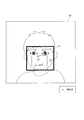
- FIG. 2 shows an example of a captured image.
- a face region 51 is extracted from a captured image 50, and feature points are extracted.
- the feature points are represented by cross-shaped markers.
- an area 52 including the nose and the mouth is set as the ROI.
- the luminance extraction unit 15 extracts the luminance used for detecting the heart rate from the R, G, and B luminances of the captured image. Although the heartbeat can be detected with any of the luminances of the colors, the luminance extracting unit 15 preferably extracts the luminance of G.
- the luminance of G has high sensitivity to hemoglobin whose amount changes with pulsation, and the heart rate detection accuracy is easily improved.
- the heartbeat detection unit 16 calculates the sum of the brightness of the captured images of each frame, and delays the vibration wave representing the temporal change of the sum of the brightness by a predetermined time.
- the heartbeat detection unit 16 calculates a heart rate from the difference between the vibration wave before the delay and each vibration wave after the delay.
- the heartbeat detection unit 16 includes an integration operation unit 161, a correction unit 162, and a correlation operation unit 163.
- the integral calculating unit 161 calculates the sum of the luminance of the captured image of each frame.
- the integration calculation unit 161 can calculate the sum of the luminances of all the regions of the captured image, but preferably calculates the sum of the luminances in the ROI set by the ROI setting unit 14. Thereby, the amount of calculation can be reduced, and the detection time of the heart rate can be shortened.
- a vibration wave representing a temporal change of the luminance is obtained.
- the amount of hemoglobin in the blood changes with the pulsation, and the brightness of the captured image changes according to the amount of hemoglobin. Therefore, the obtained vibration wave includes a heartbeat vibration wave.
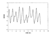
- FIG. 3 shows an example of an oscillating wave representing a temporal change of the sum of the luminances of the ROI.
- the vibration wave contains a periodic vibration wave component.
- the correction unit 162 corrects the vibration wave obtained by the integration operation unit 161.
- the correction unit 162 filters the vibration wave as one of the corrections, and removes a vibration wave component that does not affect the heartbeat.
- the frequency of the heartbeat vibration wave is generally around 1 Hz, and varies within a range of about 0.7 to 2.0 Hz depending on the physical condition.
- the correction unit 162 can remove a noise component that does not affect the heartbeat by extracting a vibration wave component having a frequency near this range, for example, a vibration wave component in a frequency band of 0.1 to 2.8 Hz. .
- filters that can be used for the filtering include a band-pass filter, a high-pass filter, and a low-pass filter.
- the correction unit 162 adjusts the amplitude of the vibration wave to a constant value by performing automatic gain control (AGC) as one of the corrections.
- AGC automatic gain control
- FIG. 4 shows a vibration wave obtained by correcting the vibration wave shown in FIG. As shown in FIG. 4, the vibration wave which is a noise component is removed by the correction, and the vibration wave in which the vibration wave component of the heartbeat is emphasized is obtained.
- the correlation calculation unit 163 delays the vibration wave obtained by the correction unit 162 by a predetermined time, and calculates a difference between the vibration wave before the delay and each vibration wave after the delay. Specifically, the correlation calculation unit 163 stores the vibration wave obtained by the correction unit 162 in a memory such as a buffer memory, and stores each vibration wave delayed for a predetermined time in a memory such as a ring buffer memory. The correlation calculator 163 calculates a difference between the held vibration wave before the delay and each vibration wave after the delay.
- FIG. 5A shows an example of the vibration wave before the delay and each vibration wave after the delay.
- each vibration wave Wi obtained by delaying the fixed time t by i times (i is an integer of 1 or more) from the original vibration wave W0 is obtained.
- the vibration wave W1 is a vibration wave delayed from the vibration wave W0 by a certain time t
- the vibration wave W2 is a vibration wave delayed further from the vibration wave W1 by a certain time t, that is, a vibration delayed from the vibration wave W0 by a time 2t. Waves.
- the correlation operation unit 163 compares the vibration wave W0 before the delay with each of the vibration waves Wi after the delay within the calculation period Tc, and calculates the difference.
- the calculation period Tc can be determined according to the cycle of the heartbeat to be detected. For example, when detecting a heart rate having a heart rate of 30 BPM or more, since one cycle is about 2 seconds, it is preferable to determine the calculation period Tc to be 4 seconds or more, which is at least two cycles or more.
- the correlation calculation unit 163 samples the vibration wave W0 before the delay and each vibration wave Wi after the delay at a constant sampling interval within the calculation period Tc.
- the sampling interval is the same time as the delay amount of each vibration wave Wi.
- the correlation calculation unit 163 calculates the sum Sj of the absolute value of the difference between the sampled vibration wave W0j before the delay and each of the delayed vibration waves Wij as shown in the following equation.
- abs () represents a function that outputs the absolute value of the operation result in ().
- W0j indicates the amplitude value of the sampled vibration wave W0 before the delay.
- Wij indicates the amplitude value of each vibration wave Wi after sampling and delay.
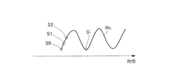
- FIG. 5B shows a waveform of the sum Sj of the absolute values of the differences.
- S0, S1, S2... Si in FIG. 5B are calculated as follows from the vibration waves W0 to Wi shown in FIG. 5A.
- S0 abs (W00-W00) + abs (W01-W01) + ⁇ ⁇ ⁇ + abs (W0i-W0i)
- S1 abs (W00-W10) + abs (W01-W11) + ⁇ ⁇ ⁇ + abs (W0i-W1i)
- S2 abs (W00-W20) + abs (W01-W21) + ⁇ ⁇ ⁇ + abs (W0i-W2i)
- ... Si abs (W00-Wi0) + abs (W01-Wi1) + ⁇ ⁇ ⁇ + abs (W0i-Wii)
- a vibration wave having a periodicity such as a heartbeat has a large difference from the original vibration wave when it is delayed for a certain period of time. Therefore, as shown in FIG. 5B, when Sj is output at the same sampling interval as the delay time, the original vibration wave W0, that is, the vibration wave Wc which is a repetitive wave with the period of the heartbeat vibration wave as the basic period, is obtained. Can be.
- the vibration wave Wc represents the autocorrelation of the original vibration wave W0, and the smaller the value, the higher the autocorrelation.
- the sum S0 thereof is also 0.
- the vibration wave Wi the waveform deviated from the vibration wave W0 by one cycle of the heartbeat
- the vibration wave W0 and the vibration wave Wi have the same or similar waveforms. Therefore, the total sum Si of the absolute value of the difference is 0 or 0. It is a value close to. As shown in FIG. 5B, it is Si that has the smallest sum after S0, and the interval between S0 and Si corresponds to one cycle of the heartbeat.
- the correlation operation unit 163 outputs the vibration wave Wi delayed during the operation period Tc. For example, when the delay time of the vibration wave W0 is 1/32 second and the calculation period Tc is 8 seconds, the correlation calculator 163 outputs the vibration waves W1 to W255. Since the sampling interval is 1/32 second, which is the same as the delay time, sampling is performed 256 times during the calculation period Tc.
- the correlation calculation unit 163 calculates the heart rate based on the cycle of the peak when the difference becomes smaller in the waveform of the difference between the vibration wave before the delay and the vibration wave after the delay. Specifically, the correlation calculation unit 163 determines a period from the time when the difference waveform starts to the time of the first peak when the difference becomes small as the heartbeat period. The correlation calculator 163 calculates and outputs a heart rate from the determined heart beat cycle. Note that since a plurality of peaks appear when the difference becomes smaller in the difference waveform, the correlation calculator 163 may calculate the heart rate based on the period between the peaks. It is preferable to calculate the number because the reliability of the heart rate is high.
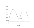
- FIG. 6 shows a waveform of a difference between the vibration wave before the delay and each vibration wave after the delay.
- one cycle of the heartbeat is from the time t1 at which the difference waveform starts to the time t2 of the first peak when the difference becomes small.
- the calculation result that the heart rate is 65.74 (BPM) is obtained from the time difference (t2 ⁇ t1).
- the determination unit 17 determines the reliability of the heart rate detected by the heart rate detection unit 16. For example, the determination unit 17 calculates a variance value of the five most recent heart rates detected by the heart rate detection unit 16. The determination unit 17 can determine high reliability if the variance value is less than the threshold value, and can determine low reliability if the variance value is equal to or greater than the threshold value. The reliability may be divided into a plurality of stages. For example, the determination unit 17 may use a plurality of thresholds for the variance value and determine the reliability in three stages.
- the determination unit 17 can determine the reliability to be high, and if the heart rate is out of the certain range, it can determine the reliability to be low.
- the determination unit 17 can also calculate or acquire the average heart rate of the user, and determine the reliability based on whether the detected heart rate is within a certain range from the average heart rate.
- the determination unit 17 can determine the reliability to be high when the value of the peak apex used to determine the period of the heartbeat is lower than the certain value, and to determine the reliability to be low when the value is equal to or more than the certain value. .
- the determination unit 17 outputs the determined reliability together with the heart rate detected by the heart rate detection unit 16.
- the heart rate can be displayed together with the reliability.
- the heart rate may be displayed in a display form according to the reliability. For example, when displaying a heart rate, a heart rate with a high reliability can be displayed in black, and a heart rate with a low reliability can be displayed in red.
- FIG. 7 shows a display example of the heart rate. As shown in FIG. 7, plots of the heart rate detected by the heart rate detecting device 1 at regular intervals are displayed in a time series. Among the respective heart rates, the heart rate determined to have high reliability is displayed by a circle marker, and the heart rate determined to have low reliability is displayed by a triangle marker.
- FIG. 8 is a flowchart showing a processing procedure when the heartbeat detecting device 1 detects a heartbeat.
- the face extraction unit 11 extracts a face area from a photographed image of the body surface of the user input from the photographing device 2 (step S1).
- the feature point extraction unit 12 extracts feature points from the detected face area (step S2).
- step S3: NO when a plurality of feature points have not been extracted, the process returns to step S1.
- the tracking unit 13 determines whether each of the feature points extracted in the captured image of the current frame and each of the feature points extracted in the captured image of the immediately preceding frame is different. The similarity is determined.
- the tracking unit 13 performs projection conversion of the captured image of the current frame so that the position of the feature point having the highest similarity matches, and causes the position of the face of the current frame to follow the position of the face of the immediately preceding frame ( Step S4).
- a noise component due to a user's movement can be reduced from a vibration wave representing a temporal change in luminance in a captured image.
- the ROI setting unit 14 sets the ROI in the captured image of the current frame in which the position of the face is followed (step S5).
- the luminance extracting unit 15 extracts the luminance of G from the photographed image input from the photographing device 2 (Step S6).
- the integration calculation unit 161 obtains the sum of the luminances of G in the set ROI and stores the sum in the memory.
- the integration operation unit 161 reads out the sum of the luminances of G within a certain period from the memory, and computes an oscillating wave representing a temporal change of the read out sum of the luminances (step S7).
- the correction unit 162 corrects the vibration wave (Step S8).
- the process returns to step S2. .
- the correlation calculation unit 163 determines the vibration wave after the correction processing. Are delayed by a fixed time, and a waveform of a difference between the vibration wave before the delay and each vibration wave after the delay is obtained.
- the correlation calculation unit 163 calculates the heart rate from the time when the waveform of the difference starts to the time when the first peak at which the difference decreases becomes one cycle of the heartbeat (step S10).
- the determination unit 17 determines the reliability of the heart rate calculated by the heart rate detection unit 16 (Step S11).
- the heart rate calculated by the heartbeat detection unit 16 is output to the display device 3 together with the reliability determined by the determination unit 17.
- the display device 3 displays the output heart rate in a display form such as a numerical value and a graph.
- the display form of the heart rate can be made different depending on the reliability.
- step S12 If there is no instruction to end the heart rate measurement (step S12: NO), the process returns to step S2. When the measurement end is instructed (step S12: YES), the present process is ended.
- the heartbeat detection device 1 detects the heart rate using the brightness of a plurality of frames of a captured image of a part of the body surface of the user and captured in time series.
- the heart rate detecting unit 16 is provided.
- the heartbeat detection unit 16 calculates the sum of the luminances of the captured images of each frame, delays the vibration wave representing the temporal change of the total luminance by a fixed time, and calculates the sum of the vibration wave before the delay and the vibration wave after the delay.
- the heart rate is calculated based on the cycle of the peak when the difference becomes smaller in the difference waveform.
- a long-period vibration wave component due to the movement of the user is included in the vibration wave in order to obtain a vibration wave component having a heartbeat periodicity from the difference between each vibration wave before and after the delay. Even if it is included, the heart rate can be detected with high accuracy. In addition, since the heart rate can be calculated by a simple calculation of addition of luminance and subtraction of each vibration wave, the heart rate can be detected with a small calculation amount. Therefore, the detection time of the heart rate can be shortened.
- a heart rate is calculated by performing frequency conversion such as Fourier transform, wavelet transform or the like on an oscillating wave representing a temporal change in luminance
- frequency conversion such as Fourier transform, wavelet transform or the like
- a period of the heart beat is obtained at a sampling number of about 256 points as in the present embodiment. It is difficult. To obtain sufficient detection accuracy of the heart rate, more sampling numbers are required.
- the frequency conversion is more susceptible to the vibration wave component having a longer cycle than the heartbeat, and the resolution is reduced. Therefore, it is difficult to accurately extract the vibration wave component of the heartbeat.
- the vibration wave of the heartbeat is accurately extracted under the influence of a vibration wave component having a longer period than the heartbeat. It is difficult.
- the period of the heartbeat is obtained from the difference between the delayed vibration waves, so that the influence of the long-period vibration wave component is small, and the period of the heartbeat can be calculated accurately.
- the heart rate can be detected only by addition and subtraction, and the amount of calculation is small, as compared with frequency conversion, autocorrelation function, and the like, which require complex calculations using functions such as integration and division. , Detection time can be reduced.
- the photographed images that can be used for detecting the heart rate are not limited to the photographed images having the above-described luminances of R, G, and B, and may be of a color space other than R, G, and B such as L * , a *, and b * . It may be a captured image having luminance.
- the luminance extracting unit 15 may extract, as the luminance used for detecting the heart rate, luminance obtained by weighting and averaging each of the R, G, and B luminances, luminance representing brightness, and the like. According to the present invention, it is possible to accurately detect the heart rate even if the luminance is other than G.
- the captured image used for detecting the heart rate is a captured image of a part of the body surface of the user
- the captured image is not a captured image of a face, but is a body surface of a part other than the face such as a wrist, a back of a hand, and a neck. May be taken.
- Reference Signs List 1 heartbeat detection device 11 face extraction unit 12 feature point extraction unit 13 follow-up unit 14 ROI setting unit 16 heartbeat detection unit 161 integration calculation unit 162 correction unit 163 correlation calculation unit 17 determination unit
Landscapes
- Health & Medical Sciences (AREA)
- Life Sciences & Earth Sciences (AREA)
- Engineering & Computer Science (AREA)
- Physics & Mathematics (AREA)
- Heart & Thoracic Surgery (AREA)
- Biophysics (AREA)
- General Health & Medical Sciences (AREA)
- Biomedical Technology (AREA)
- Medical Informatics (AREA)
- Molecular Biology (AREA)
- Surgery (AREA)
- Animal Behavior & Ethology (AREA)
- Pathology (AREA)
- Public Health (AREA)
- Veterinary Medicine (AREA)
- Cardiology (AREA)
- Physiology (AREA)
- Human Computer Interaction (AREA)
- General Physics & Mathematics (AREA)
- Multimedia (AREA)
- Theoretical Computer Science (AREA)
- Artificial Intelligence (AREA)
- Computer Vision & Pattern Recognition (AREA)
- Psychiatry (AREA)
- Signal Processing (AREA)
- Measuring Pulse, Heart Rate, Blood Pressure Or Blood Flow (AREA)
Abstract
心拍数の検出精度を高め、心拍数の検出時間を短縮する。 心拍検出装置1は、ユーザの体表の一部の撮影画像であって、時系列で撮影された複数フレームの撮影画像の輝度を用いて心拍数を検出する心拍検出部16を備え、前記心拍検出部16は、前記各フレームの撮影画像の輝度の総和を演算し、前記輝度の総和の時間的変化を表わす振動波を一定時間ずつ遅延し、遅延前の振動波と遅延後の各振動波の差の波形において前記差が小さくなるときのピークの周期により、前記心拍数を演算する。
Description
本発明は、心拍検出装置、心拍検出方法及びプログラムに関する。
従来、ユーザの撮影画像から心拍数を検出し、ストレスを評価することが行われている。ユーザの体表に接触することなく、心拍数を計測できるため、ストレス評価を簡便に行うことができる。
心拍数の検出方法としては、例えば色素成分分離を行った撮影画像の画素平均値の時間変化から心拍間隔データを求め、求めた心拍間隔データを周波数変換することで、脈拍を検出する方法が提案されている(例えば、特許文献1参照。)。
しかしながら、ユーザが少し動いただけでも撮影画像の輝度は大きく変わる。周波数変換は、ユーザの動きのような長周期成分の影響を受けやすいため、心拍数の検出精度が低下しやすい。十分な検出精度を得るためには、撮影画像のフレーム数を増やさなければならず、データ量及び演算量が増えて心拍数の検出時間が長引いてしまう。
本発明は、心拍数の検出精度を高め、心拍数の検出時間を短縮することを目的とする。
請求項1に記載の発明によれば、
ユーザの体表の一部の撮影画像であって、時系列で撮影された複数フレームの撮影画像の輝度を用いて心拍数を検出する心拍検出部を備え、
前記心拍検出部は、前記各フレームの撮影画像の輝度の総和を演算し、前記輝度の総和の時間的変化を表わす振動波を一定時間ずつ遅延し、遅延前の振動波と遅延後の各振動波の差の波形において前記差が小さくなるときのピークの周期により、前記心拍数を演算する、
心拍検出装置が提供される。
ユーザの体表の一部の撮影画像であって、時系列で撮影された複数フレームの撮影画像の輝度を用いて心拍数を検出する心拍検出部を備え、
前記心拍検出部は、前記各フレームの撮影画像の輝度の総和を演算し、前記輝度の総和の時間的変化を表わす振動波を一定時間ずつ遅延し、遅延前の振動波と遅延後の各振動波の差の波形において前記差が小さくなるときのピークの周期により、前記心拍数を演算する、
心拍検出装置が提供される。
上記心拍検出装置によれば、遅延前と遅延後の各振動波の差から、心拍の周期性を有する振動波成分を求めるため、振動波中にユーザの動きに起因する長周期の振動波成分が含まれる場合でも、精度良く心拍数を検出することができる。また、輝度の加算と各振動波の減算の簡易な演算で心拍数を演算できるため、少ない演算量で心拍数を検出することができる。したがって、心拍数の検出時間も短縮することができる。
請求項2に記載の発明によれば、
前記心拍検出部は、前記差の波形が開始した時点から最初の前記ピークが現れる時点までを1周期として、前記心拍数を演算する、
請求項1に記載の心拍検出装置が提供される。
前記心拍検出部は、前記差の波形が開始した時点から最初の前記ピークが現れる時点までを1周期として、前記心拍数を演算する、
請求項1に記載の心拍検出装置が提供される。
これにより、心拍以外の振動波の影響を減らして心拍の周期を求めることができ、心拍数の検出精度がより向上する
請求項3に記載の発明によれば、
前記心拍検出部により検出された心拍数の信頼度を判定し、前記信頼度を前記心拍数とともに出力する判定部を備える、
請求項1又は2に記載の心拍検出装置が提供される。
前記心拍検出部により検出された心拍数の信頼度を判定し、前記信頼度を前記心拍数とともに出力する判定部を備える、
請求項1又は2に記載の心拍検出装置が提供される。
これにより、心拍数とともに心拍数の信頼度を提供することができる。
請求項4に記載の発明によれば、
前記輝度が、緑の輝度である、
請求項1~3のいずれか一項に記載の心拍検出装置が提供される。
前記輝度が、緑の輝度である、
請求項1~3のいずれか一項に記載の心拍検出装置が提供される。
これにより、拍動によって量が変動するヘモグロビンに対する感度が向上し、心拍数の検出精度がより向上する。
請求項5に記載の発明によれば、
前記撮影画像にROIを設定するROI設定部を備え、
前記心拍検出部は、前記ROI内の輝度の総和を演算する、
請求項1~4のいずれか一項に記載の心拍検出装置が提供される。
前記撮影画像にROIを設定するROI設定部を備え、
前記心拍検出部は、前記ROI内の輝度の総和を演算する、
請求項1~4のいずれか一項に記載の心拍検出装置が提供される。
これにより、輝度の総和の演算量を減らすことができ、心拍数の検出時間をより短縮できる。
請求項6に記載の発明によれば、
前記撮影画像は、前記ユーザの顔の撮影画像であり、
前記各フレームの撮影画像において前記顔の特徴点を抽出する特徴点抽出部と、
前記特徴点により前記各フレームの撮影画像の顔の位置を合わせる追従部と、を備える、
請求項1~5のいずれか一項に記載の心拍検出装置が提供される。
前記撮影画像は、前記ユーザの顔の撮影画像であり、
前記各フレームの撮影画像において前記顔の特徴点を抽出する特徴点抽出部と、
前記特徴点により前記各フレームの撮影画像の顔の位置を合わせる追従部と、を備える、
請求項1~5のいずれか一項に記載の心拍検出装置が提供される。
これにより、ユーザの動きに起因するノイズ成分を減らすことができ、心拍数の検出精度がより向上する。
請求項7に記載の発明によれば、
ユーザの体表の一部の撮影画像であって、時系列で撮影された複数フレームの撮影画像の輝度を用いて心拍数を検出するステップを含み、
前記心拍数を検出するステップは、前記各フレームの撮影画像の輝度の総和を演算し、前記輝度の総和の時間的変化を表わす振動波を一定時間ずつ遅延し、遅延前の振動波と遅延後の各振動波の差の波形において前記差が小さくなるときのピークの周期により、前記心拍数を演算する、
心拍検出方法が提供される。
ユーザの体表の一部の撮影画像であって、時系列で撮影された複数フレームの撮影画像の輝度を用いて心拍数を検出するステップを含み、
前記心拍数を検出するステップは、前記各フレームの撮影画像の輝度の総和を演算し、前記輝度の総和の時間的変化を表わす振動波を一定時間ずつ遅延し、遅延前の振動波と遅延後の各振動波の差の波形において前記差が小さくなるときのピークの周期により、前記心拍数を演算する、
心拍検出方法が提供される。
上記心拍検出方法によれば、遅延前と遅延後の各振動波の差から、心拍の周期性を有する振動波成分を求めるため、振動波中にユーザの動きに起因する長周期の振動波成分が含まれる場合でも、精度良く心拍数を検出することができる。また、輝度の加算と各振動波の減算の簡易な演算で心拍数を演算できるため、少ない演算量で心拍数を検出することができる。したがって、心拍数の検出時間も短縮することができる。
請求項8に記載の発明によれば、
コンピュータに、ユーザの体表の一部の撮影画像であって、時系列で撮影された複数フレームの撮影画像の輝度を用いて心拍数を検出するステップを実行させるためのプログラムであって、
前記心拍数を検出するステップでは、前記各フレームの撮影画像の輝度の総和を演算し、前記輝度の総和の時間的変化を表わす振動波を一定時間ずつ遅延し、遅延前の振動波と遅延後の各振動波の差の波形において前記差が小さくなるときのピークの周期により、前記心拍数を演算する、
プログラムが提供される。
コンピュータに、ユーザの体表の一部の撮影画像であって、時系列で撮影された複数フレームの撮影画像の輝度を用いて心拍数を検出するステップを実行させるためのプログラムであって、
前記心拍数を検出するステップでは、前記各フレームの撮影画像の輝度の総和を演算し、前記輝度の総和の時間的変化を表わす振動波を一定時間ずつ遅延し、遅延前の振動波と遅延後の各振動波の差の波形において前記差が小さくなるときのピークの周期により、前記心拍数を演算する、
プログラムが提供される。
上記プログラムによれば、遅延前と遅延後の各振動波の差から、心拍の周期性を有する振動波成分を求めるため、振動波中にユーザの動きに起因する長周期の振動波成分が含まれる場合でも、精度良く心拍数を検出することができる。また、輝度の加算と各振動波の減算の簡易な演算で心拍数を演算できるため、少ない演算量で心拍数を検出することができる。したがって、心拍数の検出時間も短縮することができる。
本発明によれば、心拍数の検出精度を高め、心拍数の検出時間を短縮することができる。
以下、本発明の心拍検出装置、心拍検出方法及びプログラムの実施の形態について、図面を参照して説明する。
図1は、本発明の一実施形態である心拍検出装置1の構成を機能ごとに示すブロック図である。
図1に示すように、心拍検出装置1は、撮影装置2に接続され、撮影装置2から入力されたユーザの撮影画像から心拍数を検出する。また、心拍検出装置1は、表示装置3に接続され、検出した心拍数を表示装置3に出力する。
図1に示すように、心拍検出装置1は、撮影装置2に接続され、撮影装置2から入力されたユーザの撮影画像から心拍数を検出する。また、心拍検出装置1は、表示装置3に接続され、検出した心拍数を表示装置3に出力する。
(撮影装置)
撮影装置2は、ユーザの体表の一部の撮影画像であって、時系列で撮影された複数フレームの撮影画像を生成する。本実施形態において、撮影画像は、各画素がR(赤)、G(緑)及びB(青)の輝度を有するビットマップ画像である。また、撮影画像は、ユーザの顔の撮影画像である。撮影画像に顔が含まれていると、顔の特徴点の位置を元に各フレーム間で撮影画像の位置合わせが容易になる。
撮影装置2は、ユーザの体表の一部の撮影画像であって、時系列で撮影された複数フレームの撮影画像を生成する。本実施形態において、撮影画像は、各画素がR(赤)、G(緑)及びB(青)の輝度を有するビットマップ画像である。また、撮影画像は、ユーザの顔の撮影画像である。撮影画像に顔が含まれていると、顔の特徴点の位置を元に各フレーム間で撮影画像の位置合わせが容易になる。
(表示装置)
表示装置3は、心拍検出装置1から出力された心拍数を表示する。表示装置3としては、例えばLCD(Liquid Crystal Display)、タッチパネル等を使用できる。
表示装置3は、心拍検出装置1から出力された心拍数を表示する。表示装置3としては、例えばLCD(Liquid Crystal Display)、タッチパネル等を使用できる。
(心拍検出装置)
心拍検出装置1は、図1に示すように、顔抽出部11、特徴点抽出部12、追従部13、ROI設定部14、輝度抽出部15、心拍検出部16及び判定部17を備えて、構成されている。
心拍検出装置1の各構成部の処理内容は、FPGA(Field-Programmable Gate Array)、LSI(Large Scale Integration)等のハードウェアにより実現することができる。また、各構成部の処理内容は、その処理手順を記述したプログラムを、当該プログラムを記憶する記憶媒体からコンピュータが読み取って実行するソフトウェア処理により、実現することもできる。コンピュータとしては、例えばCPU(Central Processing Unit)、GPU(Graphics Processing Unit)等のプロセッサーを使用することができる。記憶媒体としては、ハードディスクやROM(Read Only Memory)等を使用することができる。
心拍検出装置1は、図1に示すように、顔抽出部11、特徴点抽出部12、追従部13、ROI設定部14、輝度抽出部15、心拍検出部16及び判定部17を備えて、構成されている。
心拍検出装置1の各構成部の処理内容は、FPGA(Field-Programmable Gate Array)、LSI(Large Scale Integration)等のハードウェアにより実現することができる。また、各構成部の処理内容は、その処理手順を記述したプログラムを、当該プログラムを記憶する記憶媒体からコンピュータが読み取って実行するソフトウェア処理により、実現することもできる。コンピュータとしては、例えばCPU(Central Processing Unit)、GPU(Graphics Processing Unit)等のプロセッサーを使用することができる。記憶媒体としては、ハードディスクやROM(Read Only Memory)等を使用することができる。
顔抽出部11は、撮影装置2から入力された撮影画像から、ユーザの顔の領域を抽出する。顔抽出部11による顔の認識方法としては、特に限定されず、例えばテンプレートマッチング等の公知の方法を使用できる。
特徴点抽出部12は、顔抽出部11により抽出された顔の領域から複数の特徴点を抽出し、各特徴点の特徴量を演算する。使用できる特徴点の抽出方法としては、特に限定されず、例えばFAST、Harris等のコーナー特徴量、SURF、KAZE等の局所特徴量、勾配ヒストグラム等が挙げられる。
追従部13は、特徴点抽出部12により抽出された特徴点の位置を元に、各フレームの撮影画像の顔の位置を合わせる。具体的には、追従部13は、撮影装置2から入力された現在のフレームと直前のフレームとで特徴量の類似度が最も高い特徴点同士の位置が一致するように、現在のフレームの撮影画像を投射変換する。これにより、現在のフレームの顔の位置を直前のフレームの顔の位置に追従させることができる。
ROI設定部14は、追従部13により顔の位置を合わせた撮影画像に、ROI(Region Of Interest)を設定する。ROI設定部14は、ROIの位置及びサイズを任意に設定できるが、口周辺又は鼻周辺を含む領域をROIに設定することが好ましい。口周辺又は鼻周辺の領域は、血中のヘモグロビン量の変化が体表面に現れやすく、心拍数の検出が容易になる。撮影画像中の口及び鼻の位置は、テンプレートマッチング等により検出できる。
図2は、撮影画像の一例を示している。
図2に示すように、撮影画像50から顔の領域51が抽出され、特徴点が抽出されている。図2において、特徴点は十字形のマーカーで表される。顔の領域51において鼻と口を含む領域52がROIとして設定されている。
図2に示すように、撮影画像50から顔の領域51が抽出され、特徴点が抽出されている。図2において、特徴点は十字形のマーカーで表される。顔の領域51において鼻と口を含む領域52がROIとして設定されている。
輝度抽出部15は、撮影画像のR、G及びBの輝度のうち、心拍数の検出に使用する輝度を抽出する。いずれの色の輝度でも心拍を検出することはできるが、輝度抽出部15は、Gの輝度を抽出することが好ましい。Gの輝度は、拍動によって量が変化するヘモグロビンに対する感度が高く、心拍数の検出精度が向上しやすい。
心拍検出部16は、各フレームの撮影画像の輝度の総和を演算し、輝度の総和の時間的変化を表わす振動波を一定時間ずつ遅延する。心拍検出部16は、遅延前の振動波と遅延後の各振動波の差から心拍数を演算する。
心拍検出部16は、図1に示すように、積分演算部161、補正部162及び相関演算部163を備えている。
心拍検出部16は、図1に示すように、積分演算部161、補正部162及び相関演算部163を備えている。
積分演算部161は、各フレームの撮影画像の輝度の総和を演算する。積分演算部161は、撮影画像の全領域の輝度の総和を演算することもできるが、ROI設定部14により設定されたROI内の輝度の総和を演算することが好ましい。これにより、演算量を減らすことができ、心拍数の検出時間を短縮できる。
各フレームの撮影画像の撮影時間に対して、各フレームの撮影画像から演算した輝度の総和をプロットすることにより、輝度の時間的変化を表わす振動波が得られる。血中のヘモグロビンの量は、拍動によって変化し、このヘモグロビンの量によって撮影画像の輝度が変化する。そのため、得られた振動波は、心拍の振動波を含む。
図3は、ROIの輝度の総和の時間的変化を表わす振動波の一例を示している。
図3に示すように、振動波には周期的な振動波成分が含まれている。
図3に示すように、振動波には周期的な振動波成分が含まれている。
補正部162は、積分演算部161により得られた振動波の補正を行う。補正部162は、補正の1つとして振動波をフィルタ処理し、心拍に影響のない振動波成分を除去する。個人差はあるが、一般的に心拍の振動波の周波数は1Hz付近であり、身体状態によって0.7~2.0Hz程度の範囲内で変動がある。補正部162は、この範囲付近の周波数の振動波成分、例えば0.1~2.8Hzの周波数帯域にある振動波成分を抽出することで、心拍に影響がないノイズ成分を除去することができる。フィルタ処理に使用できるフィルタとしては、バンドパスフィルタ、ハイパスフィルタ、ローパスフィルタ等が挙げられる。
また、補正部162は、補正の1つとして自動利得制御(AGC:Auto Gain Control)を行うことにより、振動波の振幅を一定に調整する。
図4は、図3に示す振動波を補正して得られた振動波を示している。
図4に示すように、補正によってノイズ成分である振動波が除去され、心拍の振動波成分が強調された振動波が得られている。
図4に示すように、補正によってノイズ成分である振動波が除去され、心拍の振動波成分が強調された振動波が得られている。
相関演算部163は、補正部162により得られた振動波を一定時間ずつ遅延し、遅延前の振動波と遅延後の各振動波の差を演算する。具体的には、相関演算部163は、補正部162により得られた振動波をバッファメモリ等のメモリに保持し、一定時間遅延させた各振動波をリングバッファメモリ等のメモリに保持する。相関演算部163は、保持した遅延前の振動波と遅延後の各振動波との差を演算する。
図5Aは、遅延前の振動波と遅延後の各振動波の一例を示している。
図5Aに示すように、元の振動波W0から一定時間tをそれぞれi倍(iは1以上の整数)した時間だけ遅延した各振動波Wiが得られる。例えば、振動波W1は振動波W0から一定時間tだけ遅延した振動波であり、振動波W2は振動波W1からさらに一定時間tだけ遅延した振動波、すなわち振動波W0から時間2tだけ遅延した振動波である。
図5Aに示すように、元の振動波W0から一定時間tをそれぞれi倍(iは1以上の整数)した時間だけ遅延した各振動波Wiが得られる。例えば、振動波W1は振動波W0から一定時間tだけ遅延した振動波であり、振動波W2は振動波W1からさらに一定時間tだけ遅延した振動波、すなわち振動波W0から時間2tだけ遅延した振動波である。
相関演算部163は、演算期間Tc内において、遅延前の振動波W0と、遅延後の各振動波Wiと、をそれぞれ比較し、その差を算出する。
演算期間Tcは、検出対象とする心拍の周期に応じて決定することができる。例えば、心拍数が30BPM以上の心拍を検出する場合、1周期は約2秒であるため、演算期間Tcを少なくとも2周期以上となる4秒以上に決定することが好ましい。
演算期間Tcは、検出対象とする心拍の周期に応じて決定することができる。例えば、心拍数が30BPM以上の心拍を検出する場合、1周期は約2秒であるため、演算期間Tcを少なくとも2周期以上となる4秒以上に決定することが好ましい。
具体的には、相関演算部163は、演算期間Tc内において、遅延前の振動波W0及び遅延後の各振動波Wiを、一定のサンプリング間隔でサンプリングする。サンプリング間隔は、各振動波Wiの遅延量と同じ時間である。相関演算部163は、下記式に示すように、サンプリングした遅延前の振動波W0jと遅延後の各振動波Wijの差の絶対値の総和Sjを算出する。なお、jはサンプリングした回数を表し、j=0~iである。
Sj=Σ{abs(W0j-Wij)}
上記式において、abs()は、()内の演算結果の絶対値を出力する関数を表す。W0jは、サンプリングした遅延前の振動波W0の振幅値を示す。Wijは、サンプリングした遅延後の各振動波Wiの振幅値を示す。
上記式において、abs()は、()内の演算結果の絶対値を出力する関数を表す。W0jは、サンプリングした遅延前の振動波W0の振幅値を示す。Wijは、サンプリングした遅延後の各振動波Wiの振幅値を示す。
図5Bは、差の絶対値の総和Sjの波形を示す。
例えば、図5B中のS0、S1、S2・・・Siは、図5Aに示す振動波W0~Wiから、次のように算出される。
S0=abs(W00-W00)+abs(W01-W01)+・・・+abs(W0i-W0i)
S1=abs(W00-W10)+abs(W01-W11)+・・・+abs(W0i-W1i)
S2=abs(W00-W20)+abs(W01-W21)+・・・+abs(W0i-W2i)
・・・
Si=abs(W00-Wi0)+abs(W01-Wi1)+・・・+abs(W0i-Wii)
例えば、図5B中のS0、S1、S2・・・Siは、図5Aに示す振動波W0~Wiから、次のように算出される。
S0=abs(W00-W00)+abs(W01-W01)+・・・+abs(W0i-W0i)
S1=abs(W00-W10)+abs(W01-W11)+・・・+abs(W0i-W1i)
S2=abs(W00-W20)+abs(W01-W21)+・・・+abs(W0i-W2i)
・・・
Si=abs(W00-Wi0)+abs(W01-Wi1)+・・・+abs(W0i-Wii)
心拍のように周期性を有する振動波は、一定時間遅延すると元の振動波との差が大きくなるが、さらに遅延して自己の振動波と周期が一致すると、その差が小さくなる。そのため、図5Bに示すように、遅延時間と同じサンプリング間隔でSjを出力すると、元の振動波W0、すなわち心拍の振動波の周期を基本周期とした繰り返しの波である振動波Wcを得ることができる。振動波Wcは、元の振動波W0の自己相関性を表し、値が小さいほど、自己相関性が高い。
元の振動波W0同士の差は0であるため、その総和S0も0である。例えば、振動波W0から心拍の1周期分ずれた波形が振動波Wiであるとすると、振動波W0と振動波Wiは波形が同じか類似するため、差の絶対値の総和Siは0か0に近い値となる。図5Bに示すように、S0の次に総和が小さくなるのはSiであり、S0とSi間が心拍の1周期に相当する。
なお、相関演算部163では、演算期間Tcの間、遅延した振動波Wiを出力する。
例えば、振動波W0の遅延時間が1/32秒であり、演算期間Tcが8秒の場合、相関演算部163は、振動波W1~W255を出力する。サンプリング間隔は遅延時間と同じ1/32秒であるので、演算期間Tcの間に256回のサンプリングが行われる。
例えば、振動波W0の遅延時間が1/32秒であり、演算期間Tcが8秒の場合、相関演算部163は、振動波W1~W255を出力する。サンプリング間隔は遅延時間と同じ1/32秒であるので、演算期間Tcの間に256回のサンプリングが行われる。
相関演算部163は、遅延前の振動波と遅延後の各振動波の差の波形において、差が小さくなるときのピークの周期により、心拍数を演算する。具体的には、相関演算部163は、差の波形が開始した時間から差が小さくなるときの最初のピークの時間までを心拍の周期として決定する。相関演算部163は、決定した心拍の周期から心拍数を演算して出力する。なお、差の波形において差が小さくなるときの複数のピークが現れるので、相関演算部163は、各ピーク間の周期により心拍数を演算してもよいが、上記のように最初のピークによって心拍数を演算した方が心拍数の信頼性が高く、好ましい。
図6は、遅延前の振動波と遅延後の各振動波の差の波形を示している。
図6に示すように、差の波形が開始した時間t1から、差が小さくなるときの最初のピークの時間t2までが、心拍の1周期である。図6の例では、時間差(t2-t1)から、心拍数が65.74(BPM)という演算結果が得られている。
図6に示すように、差の波形が開始した時間t1から、差が小さくなるときの最初のピークの時間t2までが、心拍の1周期である。図6の例では、時間差(t2-t1)から、心拍数が65.74(BPM)という演算結果が得られている。
判定部17は、心拍検出部16により検出した心拍数の信頼度を判定する。例えば、判定部17は、心拍検出部16により検出した、直近5つの心拍数の分散値を算出する。判定部17は、分散値が閾値未満であれば高い信頼度に決定し、分散値が閾値以上であれば低い信頼度に決定することができる。信頼度は、複数段階に分けられていてもよい。例えば、判定部17は、分散値に対して複数の閾値を使用し、信頼度を3段階で判定することもできる。
また、判定部17は、心拍数が一定範囲内、例えば30~150(BPM)の範囲内にあれば高い信頼度に決定し、一定範囲外にあれば低い信頼度に決定することができる。判定部17は、ユーザの平均心拍数を演算するか取得して、検出した心拍数が平均心拍数から一定範囲内にあるか否かによって信頼度を決定することもできる。
遅延前の振動波と遅延後の各振動波の差の波形において、心拍の周期の決定に用いられたピークの頂点の値が小さいほど、差の波形は心拍の振動波に近い。よって、判定部17は、心拍の周期の決定に用いられたピークの頂点の値が一定値より低い場合は高い信頼度に決定し、一定値以上の場合は低い信頼度に決定することもできる。
判定部17は、判定した信頼度を心拍検出部16により検出された心拍数とともに出力する。表示装置3において心拍数を表示する際、心拍数を信頼度とともに表示することができる。信頼度に応じた表示形態で心拍数が表示されてもよい。例えば、心拍数を表示する際に信頼度が高い心拍数は黒色で表示し、信頼度が低い心拍数は赤色で表示することができる。
図7は、心拍数の表示例を示している。
図7に示すように、心拍検出装置1によって一定時間ごとに検出された心拍数のプロットが時系列に表示されている。各心拍数のうち、信頼度が高いと判定された心拍数は円のマーカーで表示され、信頼度が低いと判定された心拍数は三角のマーカーで表示されている。
図7に示すように、心拍検出装置1によって一定時間ごとに検出された心拍数のプロットが時系列に表示されている。各心拍数のうち、信頼度が高いと判定された心拍数は円のマーカーで表示され、信頼度が低いと判定された心拍数は三角のマーカーで表示されている。
図8は、上記心拍検出装置1において心拍を検出するときの処理手順を示すフローチャートである。
心拍検出装置1では、図8に示すように、撮影装置2から入力したユーザの体表の撮影画像から、顔抽出部11が顔の領域を抽出する(ステップS1)。特徴点抽出部12は、検出された顔の領域から特徴点を抽出する(ステップS2)。その結果、複数の特徴点が抽出されなかった場合(ステップS3:NO)、ステップS1の処理に戻る。
心拍検出装置1では、図8に示すように、撮影装置2から入力したユーザの体表の撮影画像から、顔抽出部11が顔の領域を抽出する(ステップS1)。特徴点抽出部12は、検出された顔の領域から特徴点を抽出する(ステップS2)。その結果、複数の特徴点が抽出されなかった場合(ステップS3:NO)、ステップS1の処理に戻る。
複数の特徴点が抽出された場合(ステップS3:YES)、追従部13は、現在のフレームの撮影画像において抽出された各特徴点と、直前のフレームの撮影画像において抽出された各特徴点の類似度を判定する。追従部13は、類似度が最も高い特徴点の位置が一致するように、現在のフレームの撮影画像を投射変換し、直前のフレームの顔の位置に現在のフレームの顔の位置を追従させる(ステップS4)。追従により、撮影画像中の輝度の時間的変化を表わす振動波から、ユーザの動きによるノイズ成分を減らすことができる。
ROI設定部14は、顔の位置を追従させた現在のフレームの撮影画像にROIを設定する(ステップS5)。一方、輝度抽出部15は、撮影装置2から入力した撮影画像から、Gの輝度を抽出する(ステップS6)。
心拍検出部16では、積分演算部161が、設定されたROIにおいてGの輝度の総和を求めてメモリに保存する。積分演算部161は、メモリから一定期間内のGの輝度の総和を読み出し、読み出した各輝度の総和の時間的変化を表わす振動波を演算する(ステップS7)。補正部162は、この振動波を補正する(ステップS8)。ここで、振動波を演算した撮影画像のフレーム数が一定数に達しておらず、まだ演算期間Tsに対応する振動波が得られてない場合(ステップS9:NO)、ステップS2の処理に戻る。
一方、振動波を演算した撮影画像のフレーム数が一定数に達し、演算期間Tsに対応する振動波が得られた場合(ステップS9:YES)、相関演算部163は、補正処理後の振動波を一定時間ずつ遅延し、遅延前の振動波と遅延後の各振動波の差の波形を求める。相関演算部163は、差の波形において波形が開始した時点から差が小さくなる最初のピークが現れる時点までを心拍の1周期として、心拍数を演算する(ステップS10)。
判定部17は、心拍検出部16により演算された心拍数の信頼度を判定する(ステップS11)。心拍検出部16により演算された心拍数は、判定部17により判定された信頼度とともに、表示装置3に出力される。表示装置3では、出力された心拍数が、数値、グラフ等の表示形態で表示される。心拍数の表示形態は、信頼度によって異ならせることができる。
心拍数の測定終了の指示がなければ(ステップS12:NO)、ステップS2に戻る。測定終了が指示された場合は(ステップS12:YES)、本処理を終了する。
以上のように、本実施形態の心拍検出装置1は、ユーザの体表の一部の撮影画像であって、時系列で撮影された複数フレームの撮影画像の輝度を用いて心拍数を検出する心拍検出部16を備える。心拍検出部16は、各フレームの撮影画像の輝度の総和を演算し、輝度の総和の時間的変化を表わす振動波を一定時間ずつ遅延し、遅延前の振動波と遅延後の各振動波の差の波形において差が小さくなるときのピークの周期により、心拍数を演算する。
上記実施形態によれば、遅延前と遅延後の各振動波の差から、心拍の周期性を有する振動波成分を求めるため、振動波中にユーザの動きに起因する長周期の振動波成分が含まれる場合でも、精度良く心拍数を検出することができる。また、輝度の加算と各振動波の減算の簡易な演算で心拍数を演算できるため、少ない演算量で心拍数を検出することができる。したがって、心拍数の検出時間も短縮することができる。
輝度の時間的変化を表わす振動波に対し、フーリエ変換、ウェーブレット変換等の周波数変換を行うことで心拍数を演算する場合、本実施形態のように256ポイント程度のサンプリング数では心拍の周期を求めることは難しい。心拍数の十分な検出精度を得るにはより多くのサンプリング数を必要とする。また、周波数変換は、心拍よりも長周期の振動波成分の影響を受けやすく、分解能が低くなるため、心拍の振動波成分を精度良く抽出することが難しい。
輝度の時間的変化を表わす振動波に対し、自己相関関数を使用して心拍数を演算する場合も、心拍より長周期の振動波成分の影響を受けて、心拍の振動波を精度良く抽出することが難しい。なお、自己相関関数は、一般的に、R(t、s)=E[(Xt-μ)(Xs-μ)]/σ2(Xt及びXsはそれぞれ時刻 t及びsにおける値、μはXtの平均、σ2は分散、Eは期待値を表わす。)の式で表される。
一方、本実施形態によれば、遅延した各振動波の差により心拍の周期を求めるため、長周期の振動波成分の影響が少なく、心拍の周期を精度良く演算することができる。また、積算や除算、関数を用いた複雑な演算が必要な周波数変換、自己相関関数等に比べて、本実施形態によれば、加算と減算のみで心拍数を検出でき、演算量が少ないため、検出時間を短縮できる。
上記実施形態は本発明の好適な一例であり、これに限定されない。本発明の技術的思想の範囲内で適宜変更可能である。
例えば、心拍数の検出に使用できる撮影画像は、上述したR、G及びBの輝度を有する撮影画像に限られず、L*、a*及びb*等のR、G及びB以外の色空間の輝度を有する撮影画像であってもよい。また、輝度抽出部15は、心拍数の検出に使用する輝度として、R、G及びBの各輝度を重み付け平均して得られた輝度、明度を表わす輝度等を抽出してもよい。本発明によれば、G以外の輝度であっても、精度良く心拍数を検出することができる。
例えば、心拍数の検出に使用できる撮影画像は、上述したR、G及びBの輝度を有する撮影画像に限られず、L*、a*及びb*等のR、G及びB以外の色空間の輝度を有する撮影画像であってもよい。また、輝度抽出部15は、心拍数の検出に使用する輝度として、R、G及びBの各輝度を重み付け平均して得られた輝度、明度を表わす輝度等を抽出してもよい。本発明によれば、G以外の輝度であっても、精度良く心拍数を検出することができる。
また、心拍数の検出に用いる撮影画像は、ユーザの体表の一部の撮影画像であれば、顔の撮影画像ではなく、例えば手首や手の甲、首等の顔以外の他の部位の体表の撮影画像であってもよい。
本出願は、2018年6月28日に出願された日本特許出願である特願2018-122754号に基づく優先権を主張し、当該日本特許出願のすべての記載内容を援用する。
1 心拍検出装置
11 顔抽出部
12 特徴点抽出部
13 追従部
14 ROI設定部
16 心拍検出部
161 積分演算部
162 補正部
163 相関演算部
17 判定部
11 顔抽出部
12 特徴点抽出部
13 追従部
14 ROI設定部
16 心拍検出部
161 積分演算部
162 補正部
163 相関演算部
17 判定部
Claims (8)
- ユーザの体表の一部の撮影画像であって、時系列で撮影された複数フレームの撮影画像の輝度を用いて心拍数を検出する心拍検出部を備え、
前記心拍検出部は、前記各フレームの撮影画像の輝度の総和を演算し、前記輝度の総和の時間的変化を表わす振動波を一定時間ずつ遅延し、遅延前の振動波と遅延後の各振動波の差の波形において前記差が小さくなるときのピークの周期により、前記心拍数を演算する、
心拍検出装置。 - 前記心拍検出部は、前記差の波形が開始した時点から最初の前記ピークが現れる時点までを1周期として、前記心拍数を演算する、
請求項1に記載の心拍検出装置。 - 前記心拍検出部により検出された心拍数の信頼度を判定し、前記信頼度を前記心拍数とともに出力する判定部を備える、
請求項1又は2に記載の心拍検出装置。 - 前記輝度が、緑の輝度である、
請求項1~3のいずれか一項に記載の心拍検出装置。 - 前記撮影画像にROIを設定するROI設定部を備え、
前記心拍検出部は、前記ROI内の輝度の総和を演算する、
請求項1~4のいずれか一項に記載の心拍検出装置。 - 前記撮影画像は、前記ユーザの顔の撮影画像であり、
前記各フレームの撮影画像において前記顔の特徴点を抽出する特徴点抽出部と、
前記特徴点により前記各フレームの撮影画像の顔の位置を合わせる追従部と、を備える、
請求項1~5のいずれか一項に記載の心拍検出装置。 - ユーザの体表の一部の撮影画像であって、時系列で撮影された複数フレームの撮影画像の輝度を用いて心拍数を検出するステップを含み、
前記心拍数を検出するステップは、前記各フレームの撮影画像の輝度の総和を演算し、前記輝度の総和の時間的変化を表わす振動波を一定時間ずつ遅延し、遅延前の振動波と遅延後の各振動波の差の波形において前記差が小さくなるときのピークの周期により、前記心拍数を演算する、
心拍検出方法。 - コンピュータに、ユーザの体表の一部の撮影画像であって、時系列で撮影された複数フレームの撮影画像の輝度を用いて心拍数を検出するステップを実行させるためのプログラムであって、
前記心拍数を検出するステップでは、前記各フレームの撮影画像の輝度の総和を演算し、前記輝度の総和の時間的変化を表わす振動波を一定時間ずつ遅延し、遅延前の振動波と遅延後の各振動波の差の波形において前記差が小さくなるときのピークの周期により、前記心拍数を演算する、
プログラム。
Priority Applications (4)
| Application Number | Priority Date | Filing Date | Title |
|---|---|---|---|
| CN201980043332.9A CN112384135A (zh) | 2018-06-28 | 2019-06-03 | 心搏检测装置、心搏检测方法以及程序 |
| JP2020527325A JPWO2020003910A1 (ja) | 2018-06-28 | 2019-06-03 | 心拍検出装置、心拍検出方法及びプログラム |
| DE112019003225.9T DE112019003225T5 (de) | 2018-06-28 | 2019-06-03 | Herzschlagdetektionsvorrichtung, Herzschlagdetektionsverfahren und Programm |
| US16/973,634 US20210244287A1 (en) | 2018-06-28 | 2019-06-03 | Heartbeat detection device, heartbeat detection method, and program |
Applications Claiming Priority (2)
| Application Number | Priority Date | Filing Date | Title |
|---|---|---|---|
| JP2018-122754 | 2018-06-28 | ||
| JP2018122754 | 2018-06-28 |
Publications (1)
| Publication Number | Publication Date |
|---|---|
| WO2020003910A1 true WO2020003910A1 (ja) | 2020-01-02 |
Family
ID=68986477
Family Applications (1)
| Application Number | Title | Priority Date | Filing Date |
|---|---|---|---|
| PCT/JP2019/021961 Ceased WO2020003910A1 (ja) | 2018-06-28 | 2019-06-03 | 心拍検出装置、心拍検出方法及びプログラム |
Country Status (5)
| Country | Link |
|---|---|
| US (1) | US20210244287A1 (ja) |
| JP (1) | JPWO2020003910A1 (ja) |
| CN (1) | CN112384135A (ja) |
| DE (1) | DE112019003225T5 (ja) |
| WO (1) | WO2020003910A1 (ja) |
Cited By (7)
| Publication number | Priority date | Publication date | Assignee | Title |
|---|---|---|---|---|
| CN113951855A (zh) * | 2021-02-01 | 2022-01-21 | 南京云思创智信息科技有限公司 | 基于人脸的非接触式心率测量方法 |
| JP2022059291A (ja) * | 2020-10-01 | 2022-04-13 | コニカミノルタ株式会社 | 生体情報監視装置、生体情報監視システム及びプログラム |
| WO2022201505A1 (ja) * | 2021-03-26 | 2022-09-29 | 三菱電機株式会社 | 脈波検出装置及び脈波検出方法 |
| CN118334020A (zh) * | 2024-06-12 | 2024-07-12 | 长春大学 | 一种基于面部视频流的高精度实时心率监测方法和系统 |
| US20240358304A1 (en) * | 2022-01-25 | 2024-10-31 | Panasonic Intellectual Property Management Co., Ltd. | Information processing method, information processing system, and recording medium |
| GB2605401B (en) * | 2021-03-30 | 2025-02-26 | Vastmindz Ai Ltd | System and method of estimating vital signs of user using artificial intelligence |
| US12521068B2 (en) | 2022-03-18 | 2026-01-13 | Nikhil D Sehgal | System and method of estimating vital signs of user using artificial intelligence |
Families Citing this family (1)
| Publication number | Priority date | Publication date | Assignee | Title |
|---|---|---|---|---|
| JP7204077B2 (ja) * | 2018-09-07 | 2023-01-16 | 株式会社アイシン | 脈波検出装置、車両装置、及び脈波検出プログラム |
Citations (6)
| Publication number | Priority date | Publication date | Assignee | Title |
|---|---|---|---|---|
| JP2017029318A (ja) * | 2015-07-30 | 2017-02-09 | 国立大学法人 千葉大学 | ストレスモニタリング用画像処理方法及びそのプログラム |
| WO2017060463A1 (en) * | 2015-10-08 | 2017-04-13 | Koninklijke Philips N.V. | Device, system and method for obtaining vital sign information of a subject |
| JP2017510324A (ja) * | 2014-02-12 | 2017-04-13 | コーニンクレッカ フィリップス エヌ ヴェKoninklijke Philips N.V. | 反射された及び透過された光に基づき対象のバイタルサインを決定するデバイス、システム及び方法 |
| CN106618542A (zh) * | 2015-10-28 | 2017-05-10 | 中国科学院上海高等研究院 | 一种去噪心率信号检测装置及方法 |
| US20170156632A1 (en) * | 2015-08-14 | 2017-06-08 | Albert Joseph Swiston | Ingestible devices and methods for physiological status monitoring |
| WO2017199597A1 (ja) * | 2016-05-20 | 2017-11-23 | ソニー株式会社 | 生体情報処理装置、生体情報処理方法、及び情報処理装置 |
Family Cites Families (18)
| Publication number | Priority date | Publication date | Assignee | Title |
|---|---|---|---|---|
| US20140073969A1 (en) * | 2012-09-12 | 2014-03-13 | Neurosky, Inc. | Mobile cardiac health monitoring |
| JP6090424B2 (ja) * | 2013-02-26 | 2017-03-08 | 株式会社村田製作所 | 脈波伝播時間計測装置 |
| JP6486839B2 (ja) * | 2013-03-04 | 2019-03-20 | コーニンクレッカ フィリップス エヌ ヴェKoninklijke Philips N.V. | 速い動きの構造の超音波撮像 |
| JP6191517B2 (ja) * | 2014-03-14 | 2017-09-06 | 富士通株式会社 | 検出装置、検出プログラム、及び検出方法 |
| JPWO2016006027A1 (ja) * | 2014-07-07 | 2017-04-27 | 富士通株式会社 | 脈波検出方法、脈波検出プログラム及び脈波検出装置 |
| US10736517B2 (en) * | 2014-10-09 | 2020-08-11 | Panasonic Intellectual Property Management Co., Ltd. | Non-contact blood-pressure measuring device and non-contact blood-pressure measuring method |
| JP6683367B2 (ja) * | 2015-03-30 | 2020-04-22 | 国立大学法人東北大学 | 生体情報計測装置、生体情報計測方法及び生体情報計測プログラム |
| KR101779018B1 (ko) * | 2015-11-11 | 2017-09-26 | (주)비스토스 | 초음파 도플러 태아감시 장치의 심박 검출 신호처리 방법 |
| EP3378384A4 (en) * | 2015-11-20 | 2018-10-24 | Fujitsu Limited | Information processing device, information processing method, and information processing program |
| CN105989357A (zh) * | 2016-01-18 | 2016-10-05 | 合肥工业大学 | 一种基于人脸视频处理的心率检测方法 |
| TW201801671A (zh) * | 2016-07-11 | 2018-01-16 | 義明科技股份有限公司 | 心率偵測方法 |
| US20180085014A1 (en) * | 2016-09-23 | 2018-03-29 | Panasonic Intellectual Property Management Co., Ltd. | Pulse wave measuring apparatus, method for measuring pulse waves, and recording medium |
| CN107960989B (zh) * | 2016-10-20 | 2022-02-08 | 松下知识产权经营株式会社 | 脉搏波计测装置以及脉搏波计测方法 |
| JP2018114266A (ja) * | 2017-01-19 | 2018-07-26 | パナソニックIpマネジメント株式会社 | 脈波計測装置、制御方法、及び、プログラム |
| US10423893B2 (en) * | 2017-08-04 | 2019-09-24 | Hannes Bendfeldt | Adaptive interface for screen-based interactions |
| TWI646941B (zh) * | 2017-08-09 | 2019-01-11 | 緯創資通股份有限公司 | 生理訊號量測系統及其量測生理訊號之方法 |
| CN112070067B (zh) * | 2020-10-12 | 2023-11-21 | 乐普(北京)医疗器械股份有限公司 | 一种光体积描计信号的散点图分类方法和装置 |
| US20240024416A1 (en) * | 2020-10-30 | 2024-01-25 | Gemini Therapeutics Sub, Inc. | Methods for treating inflammatory ocular diseases with complement factor h |
-
2019
- 2019-06-03 CN CN201980043332.9A patent/CN112384135A/zh active Pending
- 2019-06-03 US US16/973,634 patent/US20210244287A1/en not_active Abandoned
- 2019-06-03 DE DE112019003225.9T patent/DE112019003225T5/de not_active Withdrawn
- 2019-06-03 WO PCT/JP2019/021961 patent/WO2020003910A1/ja not_active Ceased
- 2019-06-03 JP JP2020527325A patent/JPWO2020003910A1/ja active Pending
Patent Citations (6)
| Publication number | Priority date | Publication date | Assignee | Title |
|---|---|---|---|---|
| JP2017510324A (ja) * | 2014-02-12 | 2017-04-13 | コーニンクレッカ フィリップス エヌ ヴェKoninklijke Philips N.V. | 反射された及び透過された光に基づき対象のバイタルサインを決定するデバイス、システム及び方法 |
| JP2017029318A (ja) * | 2015-07-30 | 2017-02-09 | 国立大学法人 千葉大学 | ストレスモニタリング用画像処理方法及びそのプログラム |
| US20170156632A1 (en) * | 2015-08-14 | 2017-06-08 | Albert Joseph Swiston | Ingestible devices and methods for physiological status monitoring |
| WO2017060463A1 (en) * | 2015-10-08 | 2017-04-13 | Koninklijke Philips N.V. | Device, system and method for obtaining vital sign information of a subject |
| CN106618542A (zh) * | 2015-10-28 | 2017-05-10 | 中国科学院上海高等研究院 | 一种去噪心率信号检测装置及方法 |
| WO2017199597A1 (ja) * | 2016-05-20 | 2017-11-23 | ソニー株式会社 | 生体情報処理装置、生体情報処理方法、及び情報処理装置 |
Cited By (11)
| Publication number | Priority date | Publication date | Assignee | Title |
|---|---|---|---|---|
| JP2022059291A (ja) * | 2020-10-01 | 2022-04-13 | コニカミノルタ株式会社 | 生体情報監視装置、生体情報監視システム及びプログラム |
| JP7596696B2 (ja) | 2020-10-01 | 2024-12-10 | コニカミノルタ株式会社 | 生体情報監視装置、生体情報監視システム及びプログラム |
| CN113951855A (zh) * | 2021-02-01 | 2022-01-21 | 南京云思创智信息科技有限公司 | 基于人脸的非接触式心率测量方法 |
| CN113951855B (zh) * | 2021-02-01 | 2024-08-02 | 南京云思创智信息科技有限公司 | 基于人脸的非接触式心率测量方法 |
| WO2022201505A1 (ja) * | 2021-03-26 | 2022-09-29 | 三菱電機株式会社 | 脈波検出装置及び脈波検出方法 |
| JPWO2022201505A1 (ja) * | 2021-03-26 | 2022-09-29 | ||
| JP7615302B2 (ja) | 2021-03-26 | 2025-01-16 | 三菱電機株式会社 | 脈波検出装置及び脈波検出方法 |
| GB2605401B (en) * | 2021-03-30 | 2025-02-26 | Vastmindz Ai Ltd | System and method of estimating vital signs of user using artificial intelligence |
| US20240358304A1 (en) * | 2022-01-25 | 2024-10-31 | Panasonic Intellectual Property Management Co., Ltd. | Information processing method, information processing system, and recording medium |
| US12521068B2 (en) | 2022-03-18 | 2026-01-13 | Nikhil D Sehgal | System and method of estimating vital signs of user using artificial intelligence |
| CN118334020A (zh) * | 2024-06-12 | 2024-07-12 | 长春大学 | 一种基于面部视频流的高精度实时心率监测方法和系统 |
Also Published As
| Publication number | Publication date |
|---|---|
| DE112019003225T5 (de) | 2021-03-11 |
| US20210244287A1 (en) | 2021-08-12 |
| JPWO2020003910A1 (ja) | 2021-08-05 |
| CN112384135A (zh) | 2021-02-19 |
Similar Documents
| Publication | Publication Date | Title |
|---|---|---|
| JPWO2020003910A1 (ja) | 心拍検出装置、心拍検出方法及びプログラム | |
| JP6349075B2 (ja) | 心拍数測定装置及び心拍数測定方法 | |
| US9795306B2 (en) | Method of estimating blood pressure based on image | |
| US10292602B2 (en) | Blood flow index calculating method, blood flow index calculating apparatus, and recording medium | |
| US20170112382A1 (en) | Pulse-wave detection method, pulse-wave detection device, and computer-readable recording medium | |
| JP6052027B2 (ja) | 脈波検出装置、脈波検出プログラムおよび脈波検出方法 | |
| US9962126B2 (en) | Signal processor, signal processing method, and recording medium | |
| JP6167614B2 (ja) | 血流指標算出プログラム、血流指標算出装置および血流指標算出方法 | |
| US20210186346A1 (en) | Information processing device, non-transitory computer-readable medium, and information processing method | |
| JP6115263B2 (ja) | 脈波検出装置、脈波検出方法及び脈波検出プログラム | |
| JP6928219B2 (ja) | 脈拍周期検出装置、脈拍周期検出方法、脈拍周期検出プログラム、及び脈波検出装置 | |
| Rumiński | Reliability of pulse measurements in videoplethysmography | |
| JP6135255B2 (ja) | 心拍測定プログラム、心拍測定方法及び心拍測定装置 | |
| CN111513701A (zh) | 心率检测方法、装置、计算机设备和可读存储介质 | |
| CN106073745A (zh) | 基于智能手机的心率检测方法 | |
| US20190029600A1 (en) | Signal processing method and apparatus | |
| WO2018173484A1 (ja) | 脈波伝播速度測定システム、撮像装置および脈波伝播速度測定方法 | |
| CN104902809A (zh) | 用于减少ecg信号中的运动伪影的方法和装置 | |
| JP7237768B2 (ja) | 生体情報検出装置 | |
| JP2009297234A (ja) | 脈拍計測装置、脈拍計測プログラムおよび脈拍計測方法 | |
| JP6488722B2 (ja) | 脈波検出装置、脈波検出方法及び脈波検出プログラム | |
| US20250078563A1 (en) | Pulse wave detection device and pulse wave detection method | |
| JP7282897B2 (ja) | 脈拍数推定方法、装置およびシステム | |
| CN120725948A (zh) | 利用复合式远程光电容积脉搏波实现的心率侦测方法 | |
| JP2023075384A (ja) | 脈波検出システム、脈波検出方法及びプログラム |
Legal Events
| Date | Code | Title | Description |
|---|---|---|---|
| 121 | Ep: the epo has been informed by wipo that ep was designated in this application |
Ref document number: 19826473 Country of ref document: EP Kind code of ref document: A1 |
|
| ENP | Entry into the national phase |
Ref document number: 2020527325 Country of ref document: JP Kind code of ref document: A |
|
| 122 | Ep: pct application non-entry in european phase |
Ref document number: 19826473 Country of ref document: EP Kind code of ref document: A1 |