WO2020003844A1 - 保冷具、物流梱包容器、保冷対象物の輸送方法及び保冷具の製造方法 - Google Patents
保冷具、物流梱包容器、保冷対象物の輸送方法及び保冷具の製造方法 Download PDFInfo
- Publication number
- WO2020003844A1 WO2020003844A1 PCT/JP2019/020834 JP2019020834W WO2020003844A1 WO 2020003844 A1 WO2020003844 A1 WO 2020003844A1 JP 2019020834 W JP2019020834 W JP 2019020834W WO 2020003844 A1 WO2020003844 A1 WO 2020003844A1
- Authority
- WO
- WIPO (PCT)
- Prior art keywords
- storage material
- latent heat
- heat storage
- cooler
- housing portion
- Prior art date
- Legal status (The legal status is an assumption and is not a legal conclusion. Google has not performed a legal analysis and makes no representation as to the accuracy of the status listed.)
- Ceased
Links
Images







Classifications
-
- F—MECHANICAL ENGINEERING; LIGHTING; HEATING; WEAPONS; BLASTING
- F25—REFRIGERATION OR COOLING; COMBINED HEATING AND REFRIGERATION SYSTEMS; HEAT PUMP SYSTEMS; MANUFACTURE OR STORAGE OF ICE; LIQUEFACTION SOLIDIFICATION OF GASES
- F25D—REFRIGERATORS; COLD ROOMS; ICE-BOXES; COOLING OR FREEZING APPARATUS NOT OTHERWISE PROVIDED FOR
- F25D3/00—Devices using other cold materials; Devices using cold-storage bodies
-
- F—MECHANICAL ENGINEERING; LIGHTING; HEATING; WEAPONS; BLASTING
- F25—REFRIGERATION OR COOLING; COMBINED HEATING AND REFRIGERATION SYSTEMS; HEAT PUMP SYSTEMS; MANUFACTURE OR STORAGE OF ICE; LIQUEFACTION SOLIDIFICATION OF GASES
- F25D—REFRIGERATORS; COLD ROOMS; ICE-BOXES; COOLING OR FREEZING APPARATUS NOT OTHERWISE PROVIDED FOR
- F25D3/00—Devices using other cold materials; Devices using cold-storage bodies
- F25D3/02—Devices using other cold materials; Devices using cold-storage bodies using ice, e.g. ice-boxes
- F25D3/06—Movable containers
- F25D3/08—Movable containers portable, i.e. adapted to be carried personally
-
- B—PERFORMING OPERATIONS; TRANSPORTING
- B65—CONVEYING; PACKING; STORING; HANDLING THIN OR FILAMENTARY MATERIAL
- B65D—CONTAINERS FOR STORAGE OR TRANSPORT OF ARTICLES OR MATERIALS, e.g. BAGS, BARRELS, BOTTLES, BOXES, CANS, CARTONS, CRATES, DRUMS, JARS, TANKS, HOPPERS, FORWARDING CONTAINERS; ACCESSORIES, CLOSURES, OR FITTINGS THEREFOR; PACKAGING ELEMENTS; PACKAGES
- B65D81/00—Containers, packaging elements, or packages, for contents presenting particular transport or storage problems, or adapted to be used for non-packaging purposes after removal of contents
- B65D81/18—Containers, packaging elements, or packages, for contents presenting particular transport or storage problems, or adapted to be used for non-packaging purposes after removal of contents providing specific environment for contents, e.g. temperature above or below ambient
-
- F—MECHANICAL ENGINEERING; LIGHTING; HEATING; WEAPONS; BLASTING
- F28—HEAT EXCHANGE IN GENERAL
- F28D—HEAT-EXCHANGE APPARATUS, NOT PROVIDED FOR IN ANOTHER SUBCLASS, IN WHICH THE HEAT-EXCHANGE MEDIA DO NOT COME INTO DIRECT CONTACT
- F28D20/00—Heat storage plants or apparatus in general; Regenerative heat-exchange apparatus not covered by groups F28D17/00 or F28D19/00
- F28D20/02—Heat storage plants or apparatus in general; Regenerative heat-exchange apparatus not covered by groups F28D17/00 or F28D19/00 using latent heat
-
- F—MECHANICAL ENGINEERING; LIGHTING; HEATING; WEAPONS; BLASTING
- F28—HEAT EXCHANGE IN GENERAL
- F28F—DETAILS OF HEAT-EXCHANGE AND HEAT-TRANSFER APPARATUS, OF GENERAL APPLICATION
- F28F3/00—Plate-like or laminated elements; Assemblies of plate-like or laminated elements
- F28F3/12—Elements constructed in the shape of a hollow panel, e.g. with channels
- F28F3/14—Elements constructed in the shape of a hollow panel, e.g. with channels by separating portions of a pair of joined sheets to form channels, e.g. by inflation
-
- F—MECHANICAL ENGINEERING; LIGHTING; HEATING; WEAPONS; BLASTING
- F25—REFRIGERATION OR COOLING; COMBINED HEATING AND REFRIGERATION SYSTEMS; HEAT PUMP SYSTEMS; MANUFACTURE OR STORAGE OF ICE; LIQUEFACTION SOLIDIFICATION OF GASES
- F25D—REFRIGERATORS; COLD ROOMS; ICE-BOXES; COOLING OR FREEZING APPARATUS NOT OTHERWISE PROVIDED FOR
- F25D2303/00—Details of devices using other cold materials; Details of devices using cold-storage bodies
- F25D2303/08—Devices using cold storage material, i.e. ice or other freezable liquid
- F25D2303/082—Devices using cold storage material, i.e. ice or other freezable liquid disposed in a cold storage element not forming part of a container for products to be cooled, e.g. ice pack or gel accumulator
- F25D2303/0822—Details of the element
-
- F—MECHANICAL ENGINEERING; LIGHTING; HEATING; WEAPONS; BLASTING
- F25—REFRIGERATION OR COOLING; COMBINED HEATING AND REFRIGERATION SYSTEMS; HEAT PUMP SYSTEMS; MANUFACTURE OR STORAGE OF ICE; LIQUEFACTION SOLIDIFICATION OF GASES
- F25D—REFRIGERATORS; COLD ROOMS; ICE-BOXES; COOLING OR FREEZING APPARATUS NOT OTHERWISE PROVIDED FOR
- F25D2303/00—Details of devices using other cold materials; Details of devices using cold-storage bodies
- F25D2303/08—Devices using cold storage material, i.e. ice or other freezable liquid
- F25D2303/082—Devices using cold storage material, i.e. ice or other freezable liquid disposed in a cold storage element not forming part of a container for products to be cooled, e.g. ice pack or gel accumulator
- F25D2303/0822—Details of the element
- F25D2303/08222—Shape of the element
-
- Y—GENERAL TAGGING OF NEW TECHNOLOGICAL DEVELOPMENTS; GENERAL TAGGING OF CROSS-SECTIONAL TECHNOLOGIES SPANNING OVER SEVERAL SECTIONS OF THE IPC; TECHNICAL SUBJECTS COVERED BY FORMER USPC CROSS-REFERENCE ART COLLECTIONS [XRACs] AND DIGESTS
- Y02—TECHNOLOGIES OR APPLICATIONS FOR MITIGATION OR ADAPTATION AGAINST CLIMATE CHANGE
- Y02E—REDUCTION OF GREENHOUSE GAS [GHG] EMISSIONS, RELATED TO ENERGY GENERATION, TRANSMISSION OR DISTRIBUTION
- Y02E60/00—Enabling technologies; Technologies with a potential or indirect contribution to GHG emissions mitigation
- Y02E60/14—Thermal energy storage
Definitions
- the present invention relates to a cooler, a distribution packaging container, a method for transporting an object to be cooled, and a method for manufacturing a cooler.
- objects to be kept cool are packed and transported in a heat-insulating box for suppressing the inflow and outflow of heat from the ambient temperature. Further, in order to keep the object to be kept cool at a predetermined temperature, it is general to transport the object to be kept cool by storing a cool storage material in a heat insulating box. Further, as the form of the cold storage material, those in which the latent heat storage material is stored in a hard resin material such as a blow container, and those in which the latent heat storage material is stored in a soft film packaging bag are known.
- Patent Literature 1 discloses a laminated body that is flexible, has excellent heat resistance, is not bulky, has no fear of perforation or fire, and a bag formed from the laminated body.
- an outer metal foil having a thickness of 4 ⁇ m or more, an intermediate resin layer having a thickness of 5 to 40 ⁇ m, an inner metal foil having a thickness of 9 ⁇ m or more, and a self-extinguishing resin layer having a thickness of 2 to 10 g / m 2 ⁇ ⁇ A bag such as a flat bag, a square bag, or a self-supporting bag is formed by the formed laminate.
- Patent Literature 1 In the case where the cooler is leaned against the space restriction and frozen, the configuration described in Patent Literature 1 is a self-standing bag with a gusset at the bottom in order to be self-supporting in the form of a film pack. Yes, narrowing from bottom to top. For this reason, although not deformed, the filling density of the latent heat storage material in front of the latent heat storage material decreases toward the top, and uniform cold insulation performance in the front direction cannot be obtained. May not be obtained.
- the packing density means the weight of the latent heat storage material existing in a region in the vertical direction of the unit area when considering a unit area in front of the cooler.
- a bag in which a latent heat storage material is accommodated in a so-called flat bag in which two films are overlapped and their peripheral portions are bonded to each other is a front surface of the cooling device.
- the latent heat storage material in the liquid phase having fluidity is allowed to stand still with the bottom of the flat bag (in the plane direction of the flat bag) as the bottom, the uniformity of the filling density within the plane is increased.
- the uniform cooling performance is obtained in the front direction. It can be said that.
- the latent heat storage material in the liquid phase is attempted to stand with one side of the cooler stored in the flat bag as the bottom due to space restrictions, the bottom may swell and cannot stand. And the uniformity of the packing density from the bottom to the top is low, so that uniform cooling performance may not be obtained.
- One embodiment of the present invention has been made in view of the above-described problems of the related art, and in a film-packed cold storage material, it is possible to stand with one side as a bottom. It is an object of the present invention to provide a cooler, a distribution container, a transportation method using the cooler, and a method for manufacturing the cooler, which have a higher uniformity of the filling density of the latent heat storage material.
- a cool storage device is formed of a film facing each other, and a storage part in which a latent heat storage material is filled, and a latent heat storage material attached to a peripheral edge of the storage part. It has a linear external seal portion for preventing leakage, and one or more linear internal seal portions extending toward the inside of the housing portion and bonding the upper and lower surfaces inside the housing portion.
- the uniformity of the filling density of the latent heat storage material is higher than that of the cold storage device, the distribution packaging container, and the cold storage device.
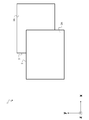
- FIG. 1 is a conceptual diagram showing the configuration of the cooler according to the first embodiment of the present invention.
- FIG. 2 is a schematic diagram when the cooler according to the first embodiment is placed on a plane.
- FIG. 3 is a schematic sectional view taken along line III-III 'of FIG.
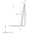
- FIG. 4 is a schematic diagram when the cooler according to the first embodiment is leaned against a wall.
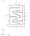
- FIG. 5 is a schematic plan view of a bag before filling a cool storage device with a latent heat storage material according to the first embodiment (Example 1).
- FIG. 6 is a schematic plan view of a bag before filling a cool storage device with a latent heat storage material according to the first embodiment (Example 3).
- FIG. 5 is a schematic plan view of a bag before filling a cool storage device with a latent heat storage material according to the first embodiment (Example 1).
- FIG. 6 is a schematic plan view of a bag before filling a cool storage device with a latent heat storage
- FIG. 7 is a dimensional diagram showing the dimensions of the cooler according to the first embodiment.
- FIG. 8 is a schematic diagram when the cooler according to the second embodiment is placed on a flat surface.
- FIG. 9 is a schematic diagram when the cooler according to the second embodiment is leaned against a wall.
- FIG. 10 is a diagram illustrating a method for manufacturing a cooler according to the second embodiment.
- FIG. 11 is a dimensional diagram showing the dimensions of the cooler according to the second embodiment.
- FIG. 12 is a schematic view when the cooler according to the third embodiment is placed on a plane.
- FIG. 13 is a dimensional diagram showing the dimensions of the cooler according to the third embodiment.
- FIG. 14 is a dimensional diagram showing the dimensions of the cooler according to the third embodiment.
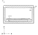
- FIG. 15 is a cross-sectional view illustrating a configuration of a physical distribution container according to the fourth embodiment of the present invention.
- FIG. 16 is a temperature characteristic diagram showing a temperature change over time of the distribution packaging container according to the fourth embodiment of the present invention.
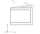
- FIG. 17 is a conceptual diagram illustrating a configuration of a cooler according to a modification.
- the z-axis indicates the thickness direction of the cooler
- the x-axis and the y-axis indicate the directions of the surface of the cooler.
- FIG. 3 is a schematic sectional view taken along the line III-III ′ of FIG.
- a latent heat storage material 5 is filled in a housing portion 4 formed of films 2 and 3 facing each other, and a linear external seal portion 6 is attached to a periphery of the housing portion 4.
- the outer seal portion 6 is formed by bonding a part of the peripheral edges of the film 2 and the film 3 together.
- the film 2 or 3 is arranged such that it is grounded on a horizontal plane (xy plane) (arranged on a plane). The same applies to FIGS. 8 and 12 described later.
- a linear internal seal portion 7 (7A, 7B, 7C) for bonding the upper surface 2A and the lower surface 3A inside the housing portion 4 extends toward the inside of the pair of opposed sides of the housing portion 4. ing. As described above, the internal seal portion 7 is formed in a comb shape inside the housing portion 4.
- the storage section 4 has a bag-like configuration, and although the volume varies depending on the application, one embodiment of the present invention assumes about 0.1 to 10 l.
- the latent heat storage material 5 has a cooling performance and is made of a material having fluidity in a liquid phase.
- the latent heat storage material 5 is preferably a water-based, long-chain hydrocarbon, a carboxylic acid having a long-chain hydrocarbon, or the like as a main agent, an alcohol, or the like.
- aqueous system is particularly preferable as the latent heat storage material 5.
- the aqueous system refers to water, an aqueous solution of an inorganic salt, an aqueous solution of an organic salt, or the like.
- the latent heat storage material 5 may contain an additive such as a supercooling inhibitor.
- the line width of the outer seal portion 6 is preferably 5 mm or more, and preferably 10 mm or more, from the viewpoint of securing a predetermined line width and preventing the latent heat storage material 5 from leaking. Also, if the line width is large, the volume of the unnecessary portion not filled with the latent heat storage material 5 increases, the area of the accommodating portion 4 filled with the latent heat storage material 5 decreases, and the cooling performance of the cool storage device 1 decreases. From the viewpoint, the line width of the outer seal portion 6 is preferably 30 mm or less.
- the line width of the outer seal portion 6 is 15 mm to 25 mm, and the inner seal portion 6 has a line width of 15 mm to 25 mm. It is particularly preferable that the width is larger than the line width of the portion 7 and surrounds the outer periphery of the housing portion 4.
- the inner seal portion 7 has the same length, for example, as shown in FIG. 2, and is parallel to the short side 1A (1A ′) of the rectangular cooler 1.
- the internal seal portions 7A, 7B, 7C alternately extend from the opposed long sides 1B and 1C of the cold insulator 1 toward the center of the short side 1A (1A '), and are formed at equal intervals.
- the internal seal portions 7A and 7C extend vertically from the long side 1C, and the internal seal portion 7B extends vertically from the long side 1B.
- FIG. 3 is a schematic sectional view taken along line III-III 'of FIG. As shown in FIG. 3, the pair of adjacent inner seal portions 7 intersects with the virtual line 1H penetrating the cooler 1 in a direction parallel to the pair of opposite sides of the housing portion 4, and thus, in the x-axis direction.
- the storage section 4 is partitioned. Thereby, when standing the cooler 1 filled with the liquid-phase latent heat storage material 5 in the housing part 4, the flow of the latent heat storage material 5 is suppressed, and the swelling due to its own weight is restricted.
- FIG. 4 is a schematic diagram when the cooler 1 according to the first embodiment is leaned against a wall.
- the cold insulator 1 is kept cold with the short side 1 ⁇ / b> A (1 ⁇ / b> A ′) leaning against a wall and the long side 1 ⁇ / b> C as the bottom.
- the latent heat storage material 5 in the liquid phase is accumulated on the lower side of the cooler 1, and the latent heat storage material 5 freezes in a state where the lower side of the cooler 1 is expanded more than the upper side.
- a portion where the adjacent inner seal portions 7 are close to each other near the center of the short side 1 ⁇ / b> A (1 ⁇ / b> A ′) serves as a swelling limiting portion 1 ⁇ / b> D for limiting the swelling of the housing portion 4.
- an arrangement is such that one side of the outer seal portion 6 is in contact with a horizontal plane (xy plane) (an arrangement leaning against a wall). The same applies to FIG. 9 described later.
- the bulge restricting portion 1D restricts the bulge of the housing portion 4 as the inner seal portions 7 adjacent to each other near the center of the short side 1A (1A ') overlap.
- the films 2 and 3 become difficult to separate, and the swelling of the housing portion 4 is restricted, so that the volume of the latent heat storage material 5 that can be filled in the housing portion 4 decreases.
- the number of the internal seal portions 7 is large, the films 2 and 3 are difficult to separate, and the swelling of the housing portion 4 is limited, so that the volume of the latent heat storage material 5 that can be filled in the housing portion 4 is reduced. Therefore, the cool keeping time of the cool keeping tool 1 is shortened. Therefore, it is necessary to appropriately adjust the number of the internal seal portions 7.
- the formation of the internal seal portion 7 forms a flow path 1E of the latent heat storage material 5 described later inside the storage portion 4, thereby increasing the filling speed of the latent heat storage material 5 into the storage portion 4 and increasing the temperature of the cold insulator 1.
- the formation of the flow path is particularly effective when the thickness of the films 2 and 3 is increased to, for example, more than 100 ⁇ m.
- the film thickness of the films 2 and 3 exceeds 100 ⁇ m, the rigidity of the housing portion 4 can be secured. However, if the film thickness is more than 200 ⁇ m, it becomes difficult to cover the cooling object 21 described later, and the cooling time such as cooling time and temperature is kept. The performance and the flexibility are deteriorated. When the flexibility performance is reduced, it becomes difficult to form the housing portion 4 in the shape of a bag, or the filling amount of the latent heat storage material 5 into the housing portion 4 decreases.
- the thickness of the films 2 and 3 is particularly preferably 130 ⁇ m to 180 ⁇ m in consideration of securing the rigidity of the storage section 4, the cool performance of the cooling device 1, and the flexibility of the storage section 4.
- the thicknesses of the films 2 and 3 are increased in this manner, the rigidity of the storage section 4 is increased, and the cold insulator 1 can be easily leaned against the wall.
- the weight of the films 2 and 3 increases, the friction between the films 2 and 3 increases, and the rigidity of the films 2 and 3 increases. For this reason, when the film thickness of the films 2 and 3 increases, the latent heat storage material 5 It is hard to invade inside.
- FIG. 5 is a schematic plan view of the bag 40 before filling the latent heat storage material 5 in Example 1 described later.
- FIG. 5 shows a state in which the bag 40 is set up in the vertical direction.
- a flow path 1E through which the latent heat storage material 5 flows when the latent heat storage material 5 is filled is formed.
- the films 2 and 3 may adhere to each other, making it difficult to fill the latent heat storage material 5.
- the passages 1 ⁇ / b> E of the latent heat storage material 5 are formed, so that the films 2 and 3 can be easily separated when the storage part 4 is filled with the latent heat storage material 5.
- the width of the flow path 1E of the latent heat storage material 5 is wide and uniform, and is approximately equal to the length of the opening 8 serving as a spout of the latent heat storage material 5.
- the filling speed of the latent heat storage material 5 increases, and the latent heat storage material 5 easily enters the inside of the housing portion 4.
- the cooling tool 1 may be provided with an opening 8 that connects the inside and the outside of the housing section 4 so that the latent heat storage material 5 can be easily filled during manufacturing.
- the channel 1E is installed so that the cooler 1 is set up vertically, the opening 8 is used as one end of the channel 1E, and the path to the other end is one way (hereinafter, referred to as one stroke). ) So that the latent heat storage material 5 can easily flow inside the housing portion 4.
- FIG. 6 is a schematic plan view of the bag 41 before filling the latent heat storage material 5 in a third embodiment described later.
- the bag 41 is provided with an opening 8A, and shows a case where the flow path 1F of the latent heat storage material 5 from the opening 8A serving as a spout of the latent heat storage material 5 is not drawn with one stroke. Since the region 1G of the storage section 4 is a region that cannot be filled using the weight of the latent heat storage material 5, the region 1G cannot be sufficiently filled with the latent heat storage material 5. As the thickness of the films 2 and 3 increases, the region 1G cannot be sufficiently filled with the latent heat storage material 5.
- the sealing part 9 provided in the step of filling the latent heat storage material 5 is, for example, a sealing part for sealing, and is provided in a step different from the external sealing part 6 attached in the step of manufacturing the housing part 4. In most cases, the seal traces of the sealing part 9 and the external seal part 6 are different. The longer the length of the opening 8 is, the easier it is to fill the latent heat storage material 5, but it is easy to leak at the time of sealing and the sealing becomes difficult. Therefore, it is preferable that the length of the opening 8 is substantially equal to the width of the flow path 1E.
- the material of the films 2 and 3 in the present embodiment is preferably a packaging material that can be thermocompression-bonded (heat-sealed) for the purpose of forming the outer seal portion 6 and the inner seal portion 7.
- a packaging material containing at least a density polyethylene (LLDPE) is included.
- the internal seal portion 7 is formed by, for example, arranging the films 2 and 3 having the surface layer of LLDPE so that the LLPDE surfaces face each other, and applying heat of, for example, 110 ° C. or more, and bonding.
- the material of the films 2 and 3 is preferably formed by laminating or vapor-depositing nylon (NY), aluminum (Al), polyethylene terephthalate (PET), etc. in addition to LLDPE.
- aluminum is preferably used as a material for the films 2 and 3 for the purpose of increasing the water vapor transmission rate or reducing the light transmission rate.
- the cooler 1 prepares a latent heat storage material 5, prepares a bag-like shape having an opening 8 in the outer seal portion 6 by using the outer seal portion 6 and the housing portion 4, and forms the inside of the housing portion 4.
- the internal sealing portion 7 is formed, the latent heat storage material 5 is filled from the opening 8, and the opening 8 is sealed with the sealing portion 9 to manufacture the device.
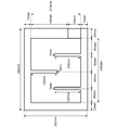
- FIG. 7 shows an example of dimensions as an example in the present embodiment.
- the cooler 1 has a short side 1A (1A ') having a length of 240 mm, a long side 1B (1C) having a length of 380 mm, and a length of the opening 8 provided in a part of the short side 1A'.
- the length was 60 mm.
- the external seal part 6 had a line width of 15 mm on the short side 1A (1A ') and a line width of 20 mm on the long side 1B (1C).
- the inner seal portion 7 has a line length of 120 mm, a line width of 5 mm, and is formed at regular intervals of 85 mm on the long side 1B (1C).
- the width of the flow path 1E is 85 mm to 90 mm.
- Films 2 and 3 had a thickness of about 160 ⁇ m, and were made of a film packaging material laminated with NY, Al, and LLDPE in this order.
- the LLDPE surfaces of the films 2 and 3 face each other to form a housing portion 4, and the housing portion 4 is bonded by an outer seal portion 6 and an inner seal portion 7.
- the piercing strength of the films 2 and 3 of this example according to the JIS standard was 30N. This can be said to be high in strength and rigidity of the films 2 and 3 of the present embodiment in view of the fact that the piercing strength of a commercially available detergent or food pouch bag is about 15N.
- an automatic filling machine is used to fill the bag before filling the latent heat storage material 5 of the cooling tool 1 shown in FIG. To fill 1200 ml of water. After filling, the opening 8 was thermocompression-bonded with an impulse sealer to form a sealing portion 9.
- Comparative Example 1 In this comparative example, the internal seal portion 7 was not formed, and the other conditions were the same as in Example 1.
- the latent heat storage material 5 was accumulated on the long side 1C side of FIG. 4, and the accommodation portion 4 was in a shape of swelling downward, and was greatly deformed and could not be leaned against the wall. .
- Example 2 In this example, the film thickness of each of the films 2 and 3 was 90 ⁇ m, and the material was a film packaging material laminated in the order of NY, PET, and LLDPE, and the other conditions were the same as in Example 1. Although the material is different from that of the first embodiment, Al of the first embodiment and PET of the present embodiment are sufficiently thin and their rigidity can be neglected. Therefore, it is considered that only the film thickness affects the rigidity of the cooler 1 simply. be able to.
- the piercing strength of the films 2 and 3 of this example according to the JIS standard was 15 N, which was equivalent to the piercing strength of a commercially available detergent or food pouch bag.
- JIS Z1707 JIS Z1707
- the cooler 1 of this embodiment was partially deformed, it could be leaned against a wall as shown in FIG.
- the latent heat storage material 5 accumulates on the long side 1C side, and the long side 1B is curved and deformed into a gentle concave shape, but it can be leaned against a wall as shown in FIG. Was.
- the deformation was large as compared with Example 1.
- Example 3 In the present embodiment, the position of the opening 8 in FIG. 5 is shifted to the position of the opening 8A as shown in FIG. 6, and other conditions are the same as those in the first embodiment.
- the filling amount of the latent heat storage material 5 was 1000 g, and the region 1G that was not on the flow path 1F in FIG. 6 was not filled with the latent heat storage material 5.
- the filling amount of the latent heat storage material 5 is slightly insufficient, and the state where the latent heat storage material 5 is not filled on the long side 1B side (upper part) is considered. Therefore, the cold insulator 1 was deformed, but it was possible to stand.
- the volume of the latent heat storage material 5 that could be actually filled in the present example was 1000 ml, which was about 80% of the volume (1200 ml) of the latent heat storage material 5 that could be filled in the bag of Example 1.
- the internal seal 7 prevents the cooler 1 from being excessively deformed, so that the cooler 1 can lean against the wall. it can. Thereby, since the cold insulator 1 can be frozen in a state of leaning against the wall, the operation and workability at the distributor can be improved, which is preferable.
- the internal seal 7 prevents the cooler 1 from being excessively deformed, it is preferable because the uniformity of the filling density of the latent heat storage material can be maintained.
- the inner seal portion 7 (7A, 7B, 7C) extends toward the inside of the pair of facing sides (long sides 1B, 1C) of the housing portion 4.
- the inner seal portion 11 (11A, 11B) is inside the pair of facing sides (short sides 1A, 1A ′) of the housing portion 4. Stretch toward.
- the length of the internal seal portion 11 is longer than half the length of the long side 1B (1C) of the rectangular cold insulator 10, and the adjacent internal seal portions 11 are parallel to the short side 1A (1A '). Then, the lines (1I) passing through the midpoints of the long sides 1B and 1C alternately intersect with each other and overlap near the center of the long side 1B (1C).
- the bulge limiting portion 1D is located at one place when viewed from the side as shown in FIG. 4, but in the present embodiment, when viewed from the side as shown in FIG.
- the bulge limiting portions 10A and 10B correspond to the number of the internal seal portions 11.
- the present embodiment as in the first embodiment, it is possible to limit the swelling of the storage section 4 due to the weight of the latent heat storage material 5 in the cooler 10, and the latent heat storage material 5 stored in the storage section 4.
- the uniformity of the packing density can be increased.
- the opening 12 and the sealing portion 13 may be provided as shown in FIG.
- a flow path 10C for the latent heat storage material 5 is formed.
- FIG. 11 shows an example of dimensions as an example in the present embodiment.
- the cold insulator 10 has a short side 1A (1A ') length of 220 mm, a long side 1B (1C) length of 380 mm, and a length of the opening 8 provided in a part of the short side 1A.
- the outer seal portion 6 had a line width of 10 mm on the short side 1A, a line width of 10 mm on the short side 1A, and 20 mm on the short side 1A 'side on the long side 1B (1C).
- the internal seal portion 11 has a line length of 270 mm, a line width of 5 mm, and the short side 1A (1A ') is parallel to the internal seal portions 11A and 11B, and the distance between the internal seal portions 11A and 11B is 60 mm.
- Each internal seal portion 11 is formed at a position 70 mm from the end of the short side 1A (1A ').
- the width of the flow path 10C is 60 mm to 70 mm.
- the deformation is hardly confirmed visually, and it can be said that the deformation is almost the same as that of the first embodiment.
- the front indicates, for example, that the surfaces of the films 2 and 3 are visible as shown in FIG. 2, and the side indicates that the films 2 and 3 are horizontal as shown in FIG. Point out that there is no Further, the projected area can be obtained from a photograph taken from a fixed point at a fixed distance from the coolers 1 and 10. As another method, the projected area can also be obtained by comparing the coolers 1 and 10 with the grids of the grid paper.
- Example 1 and Example 2 in Table 1 Under the premise that the internal sealing portion 7 is formed, if the film thickness of the films 2 and 3 exceeds 100 ⁇ m, the deformation of the cool insulator 1 is extremely small. I understand. As can be seen from Example 1 and Comparative Example 1, when the internal seal portion 7 is not formed, it is impossible to lean, and even the degree of front deformation or the degree of side deformation cannot be compared.
- Example 1 and Example 3 in Table 1 by filling the latent heat storage material 5 corresponding to the volume (1200 ml) of the storage unit 4, the latent heat storage material 5 is filled in all regions of the storage unit 4. The container 4 is filled and deformation of the container 4 is reduced.
- the angle between the long side (1B, 1C) or the short side (1A, 1A ') of the cold insulator 1 and the internal seal portion 7 is substantially a right angle.
- the angle formed between the long sides 1B and 1C of the cooler 17 and the inner seal portions 14 (14A and 14B) may be an angle other than a right angle.
- internal seal portion 14 (14A, 14B) extends toward the inside of a pair of opposed sides (short sides 1A, 1A ′) of accommodation portion 4. .
- the line length of the internal seal portion 14 is increased as compared with the first and second embodiments in which the internal seal portion 14 is formed in a right angle direction because the internal seal portion 14 is formed in an oblique direction. This makes it easier for the cooler 17 to lean against the wall.
- the latent heat storage material 5 in the liquid phase flows when a force is applied from the outside of the cooler 17 from the x-axis direction and the y-axis direction in FIG. This alleviates the stress of the inner seal portion 14 that is received, thereby increasing the impact resistance. For this reason, for example, it is possible to increase the resistance to the drop impact of the cooler 17 from the x-axis direction or the y-axis direction.
- the opening 15 and the sealing portion 16 may be provided as shown in FIG.
- a flow path 17A of the latent heat storage material 5 is formed.
- the flow path 17A can be formed wider than in the first and second embodiments in which the internal seal portion 14 is formed in a right angle direction because the internal seal portion 14 is formed in an oblique direction. Thus, narrowing the flow path 17A more than necessary is reduced. If the flow path 17A is wide, the filling speed of the latent heat storage material 5 is increased, and the productivity of the cool insulator 17 is increased.
- FIG. 13 shows an example of dimensions as an example in the present embodiment.
- the cooler 17 has a short side 1A (1A ′) having a length of 150 mm, a long side 1B (1C) having a length of 210 mm, and a length of the opening 8 provided in a part of the long side 1B.
- the outer seal part 6 had a line width of 10 mm.
- the inner seal portion 14 (14A, 14B) had a line length of 85 mm and a line width of 5 mm.
- the internal seal portion 14A is formed to be adjacent to the opening 15 of the long side 1B, and has an angle of 45 ° with the long side 1B.
- the inner seal portion 14B is formed with an end located at 80 mm from the end of the long side 1C on the short side 1A side (110 mm from the end of the short side 1A ') and has an angle of 45 ° with the long side 1C. .
- the width of the flow path 17A is 30 mm to 120 mm.
- the amount of the latent heat storage material 5 to be filled according to the outer dimensions of the cooler 17 in this embodiment was 200 g.
- the width of the flow path 17A in the present embodiment is assumed to be a vertical line starting from the internal seal portion 14, and this vertical line intersects the flow path 17A and is the closest to the internal seal portion 14 or the external seal portion 6. Distance.
- FIG. 14 shows an example of dimensions as an example in the present embodiment.
- the cooler 18 has an outer dimension of a short side 1A (1A ') having a length of 245 mm, a long side 1B (1C) having a length of 370 mm, and an opening provided in a part of the short side 1A (1A').
- the length of 18F was 150 mm.
- the outer seal portion 6 had a line width of 15 mm on the short side 1A (1A ') and a line width of 20 mm on the long side 1B (1C).
- the internal seal portions 18A, 18B, 18C, and 18D had a line length of 190 mm, 125 mm, 70 mm, and 70 mm, respectively, and a line width of 5 mm.
- the inner seal portions 18A and 18B are formed with the long sides 1C and 1B as ends, and have an angle of 45 ° with the long sides 1C and 1B.
- the inner seal portions 18C and 18D are formed with the short sides 1A and 1A 'as ends, and have an angle of 45 ° with the short sides 1A and 1A'.
- the width of the flow path 18E is 40 mm to 150 mm. In this embodiment, the amount of the latent heat storage material 5 to be filled according to the outer dimensions of the cooler 18 was 1200 g.
- the width of the flow path 18E in this embodiment is assumed to be a perpendicular line starting from the inner seal portions 18A and 18B, and the perpendicular line intersects the flow passage 18E and is adjacent to the inner seal portions 18A and 18B or the outer seal. The distance to the part 6 was set.
- the cooling device 1 (10, 17, 18) installed on the cooling object 21 such as fruits and vegetables to be cooled is stored in the container 20C.
- the inner size of the container 20C is larger than the combined size of the cooler 1 (10, 17, 18) and the object 21 to be kept cool.
- the container 20C is a heat insulating box or the like and has a heat insulating effect.
- the distribution container 20 directly cools the cooling object 21 by utilizing heat conduction by directly covering the cooling tool 1 (10, 17, 18) on the cooling object 21 inside.
- the distribution packing container 20 has a uniform filling density of the coolers 1 (10, 17, 18) according to the first to third embodiments, and thus is directly covered. In this way, it is possible to make uniform contact with the object 21 to be kept cold, and the cooling efficiency is improved. Since the lower part of the cold storage target 21 is in contact with the lower part 20B of the container 20C, the movement of the amount of heat from the cold storage target 21 is reduced.
- the cooling tool 1 When transporting the object 21, first, the cooling tool 1 is coated on the cooling object 21, and the cooling object 21 on which the cooling tool 1 is placed is moved to the cooling tool 1 and the cooling object 21.
- a container 20C having an inner size larger than the combined size.
- Example 7 a material (density at 20 ° C .: 1.036 g) obtained by adding 1% of a supercooling inhibitor calcium carbonate to a 40 wt% aqueous solution of tetrabutylammonium was used as the latent heat storage material 5 of the cooling tool 1 housed in the container 20C.
- the melting point of the material 5 was set to 12 ° C. The other points were the same as in the first embodiment.
- the latent heat storage material 5 was frozen by standing the cooler 1 against a wall with the long side 1C as the bottom as shown in FIG. 4 in a cold storage at 3 ° C. for 16 hours. At this time, the degree of front deformation and the degree of side deformation were 0.1 or less, and almost no deformation was observed.
- the cooling tool 1 was coated on the object 21 to be cooled using a robot such as a robot arm and stored in the container 20C. Since the cooler 1 is uniform without being deformed, it is easy for the robot to grasp the cooler 1 and no extra time is required for fine adjustment when the robot grasps the cooler 1.
- the logistics packaging container 20 was allowed to stand in a constant temperature room with a temperature variable function for 12 hours, and the temperature in the constant temperature room was changed between 30 ° C. and 40 ° C. to simulate a transport environment in midsummer.
- Comparative Example 2 As a comparative example of the present embodiment, three hard containers (blow containers) filled with 400 ml of the same latent heat storage material 5 as in Example 7 instead of the cooler 1 are prepared to cool the space inside the container 20C. It was installed in. The total volume of the latent heat storage material 5 was 1200 ml as in Example 7, and one of the hard containers was installed in the lower portion 20B, and two of the hard containers were hooked on a lid of the container 20C and arranged in the upper portion 20A.
- FIG. 16 is a graph showing temperature changes over time of the object 21 of Example 7 and the object 21 of Comparative Example 2 in a constant temperature room.
- a graph 22 shows a temperature change over time in the constant temperature room
- a graph 23 shows a temperature change over time of the cold storage object 21 of Comparative Example 2
- a graph 24 shows a temperature change over time of the cold storage object 21 of Example 7. Indicates a change.
- the temperature of the cooling object 21 exceeds 15 ° C. after about 2 hours. This is because in the arrangement of the hard container as in Comparative Example 2, there is a space between the upper hard container and the object 21 to be kept cool, and the temperature easily rises due to heat inflow from the outside of the container 20C.
- the temperature of the cold storage object 21 can be kept at 15 ° C. or less even after elapse of 12 hours.
- This is the melting point of the latent heat storage material 5 that covers the cold-holding object 21 and reduces the space between the cold-holding object 21 and the cold-holding tool 1 in the cold-holding with the cold-holding tool 1 of the seventh embodiment.
- the cooler 1 according to the present embodiment has a small change in shape even when frozen in a standing state, and has a high uniform filling density of the latent heat storage material 5. Can be kept cool.
- the outer seal portion 6 may surround the entire periphery of the housing portion 4 in order to prevent the latent heat storage material 5 from leaking.
- the seal portion 32 may be configured to be attached to a part of the outer periphery of the housing portion 33.
- the external seal portion 32 may be attached so as to surround the outer periphery of the housing portion 33.
- the surfaces of the films 2 and 3 in the coolers 1, 10, 17 and 18 are rectangular, one embodiment of the present invention is not limited to this, and may be, for example, circular or elliptical.
- the cold insulators 1, 10, 17, 18 are rectangular, the corners may have a round shape with a radius of curvature, which makes the handling of the cold insulators 1, 10, 17, 18 safer. Can increase.
Landscapes
- Engineering & Computer Science (AREA)
- Mechanical Engineering (AREA)
- Physics & Mathematics (AREA)
- Thermal Sciences (AREA)
- General Engineering & Computer Science (AREA)
- Chemical & Material Sciences (AREA)
- Combustion & Propulsion (AREA)
- Packages (AREA)
Abstract
フィルムパックされた蓄冷材において、ある一辺を底にして立掛けることが可能で、立掛けた場合にも、潜熱蓄冷材の充填密度の均一性がより高い保冷具、物流梱包容器、保冷対象物の輸送方法及び保冷具の製造方法を提供する。保冷具は、互いに向かい合わせたフィルムから形成され、内部に潜熱蓄熱材が充填される収容部と、収容部の周縁に貼付し潜熱蓄熱材の漏洩を防ぐ線状の外部シール部と、収容部の内側に向かって延伸し、収容部の内部の上面及び下面を接着する線状の1又は複数の内部シール部と、を備える。
Description
本発明は、保冷具、物流梱包容器、保冷対象物の輸送方法及び保冷具の製造方法に関する。
本願は、2018年6月29日に、日本に出願された特願2018-125107に優先権を主張し、その内容をここに援用する。
本願は、2018年6月29日に、日本に出願された特願2018-125107に優先権を主張し、その内容をここに援用する。
低温物流システムでは、保冷対象物が、環境温度からの熱の流出入を抑制する為の断熱性の箱内に梱包されて輸送される。また、保冷対象物を所定の温度に保つために、断熱性の箱内に蓄冷材を収納して保冷対象物を輸送することが一般的になされている。また、蓄冷材の形態としては、潜熱蓄熱材をブロー容器のような硬質の樹脂材に収容したものや、軟質のフィルム包材の袋に収容されたものが知られている。一方で、輸送の際の保冷性能を考慮すると、フィルム包材の袋に収容されたものは、保冷対象物に直接保冷剤を接触させることで、固相状態から液相状態に変化する際に保冷対象物に沿うように変形しながら保冷することができる。そのため、保冷対象物の外部から保冷対象物への熱流入の影響が少なく、潜熱蓄熱材の融点付近にて温度管理された保冷が実現できる。特許文献1には、フレキシブルで耐熱性に優れ嵩ばらず、穿孔や火災の心配がない積層体及びその積層体によって形成した袋が開示されている。特許文献1に記載の発明においては、厚さ4μm以上の外面金属箔、厚さ5~40μmの中間樹脂層、厚さ9μm以上の内面金属箔、2~10g/m2 の自己消火性樹脂層から構成される積層体によって平袋、角袋、自立袋などの袋が形成される。特許文献1の袋に、潜熱蓄熱材を収容し、フィルムパックすることで、保冷具として保冷対象物に直接配置し保冷輸送することも想定できる。
しかしながら、空間的な制約を考慮して保冷具を立て掛けて凍結させた場合には、特許文献1に記載された構成は、フィルムパックの形態で自立させるために、底部にマチのある自立袋であり、底部から上部に向かって幅が狭まる。このため、変形はしないものの潜熱蓄熱材の正面における、潜熱蓄熱材の充填密度は上部に向かって小さくなり、正面方向における均一な保冷性能が得られず、保冷剤の一部分において所望の保冷性能を得られないことがある。なお、充填密度とは、保冷具の正面のある単位面積を考えたときに、その単位面積の垂直方向の領域に存在する潜熱蓄熱材の重量を意味する。
一方で、フィルムパックされた保冷具の形態として、2枚のフィルムを重なり合わせ、その周縁部が貼り合わされた袋、いわゆる平袋に、潜熱蓄熱材が収容されたものは、保冷具の正面(平袋の面方向)を底にして静置した場合には、流動性を有する液相状態の潜熱蓄熱材は平らに均され、充填密度の面内での均一性が高くなる。
すなわち、平袋に潜熱蓄熱材が収容された保冷具の正面を底にして凍結した場合には、正面方向において均一な保冷性能が得られるため、平袋はフィルム包材の袋として優れた形態といえる。しかし、空間的の制限の理由から液相状態の潜熱蓄熱材が平袋に収容された保冷具の一辺を底にして立掛けようとした場合には、底部が膨れて、立掛けなれない可能性や、底部から上部に向かって充填密度の均一性が低く、均一な保冷性能が得られないことがある。
本発明の一つの態様は、上記従来技術の問題に鑑みなされたものであって、フィルムパックされた蓄冷材において、ある一辺を底にして立掛けることが可能で、立掛けた場合にも、潜熱蓄冷材の充填密度の均一性がより高い保冷具、物流梱包容器、保冷具を用いた輸送方法及び保冷具の製造方法を提供することを目的とする。
上記課題を解決するため、本発明の一態様の保冷具は、互いに向かい合わせたフィルムから形成され、内部に潜熱蓄熱材が充填される収容部と、収容部の周縁に貼付し潜熱蓄熱材の漏洩を防ぐ線状の外部シール部と、収容部の内側に向かって延伸し、収容部の内部の上面及び下面を接着する線状の1又は複数の内部シール部と、を備える。
本発明の一態様によれば、フィルムパックされた蓄冷材において、ある一辺を底にして立掛けた場合にも、潜熱蓄冷材の充填密度の均一性がより高い保冷具、物流梱包容器、保冷対象物の輸送方法及び保冷具の製造方法を提供することができる。
以下、本発明の実施の形態について、図面を参照しながら説明する。図中のz軸は保冷具の膜厚方向を示し、x軸及びy軸は保冷具の面の方向を示すものとする。
[第1の実施の形態]
図1、2に本実施の形態における保冷具1を示す。また、図3は、図2のIII-III’の概略断面図である。図1に示すように保冷具1は、互いに向かい合うフィルム2,3から形成される収容部4の内部に潜熱蓄熱材5が充填され、収容部4の周縁に線状の外部シール部6が貼付されることで流動性を有する潜熱蓄熱材5の漏洩が防がれている。なお外部シール部6は、フィルム2及びフィルム3の周縁の一部分を貼り合わせることで形成される。また図2においてはフィルム2又は3が水平面(xy平面)に接地しているような配置(平面に置いた配置)となっている。後述の図8、図12においても同様とする。
図1、2に本実施の形態における保冷具1を示す。また、図3は、図2のIII-III’の概略断面図である。図1に示すように保冷具1は、互いに向かい合うフィルム2,3から形成される収容部4の内部に潜熱蓄熱材5が充填され、収容部4の周縁に線状の外部シール部6が貼付されることで流動性を有する潜熱蓄熱材5の漏洩が防がれている。なお外部シール部6は、フィルム2及びフィルム3の周縁の一部分を貼り合わせることで形成される。また図2においてはフィルム2又は3が水平面(xy平面)に接地しているような配置(平面に置いた配置)となっている。後述の図8、図12においても同様とする。
また収容部4には収容部4の内部の上面2A及び下面3Aを接着する線状の内部シール部7(7A,7B,7C)が収容部4の一対の向き合う辺の内側に向かって延伸している。このように内部シール部7は収容部4の内部において櫛歯状に形成されている。
収容部4は、袋状の構成となっており、体積は用途により異なるが本願発明の一態様においては0.1l~10l程度を想定している。潜熱蓄熱材5は保冷性能を備えており液相状態で流動性を有する材料から生成される。
潜熱蓄熱材5は、主剤として水系、長鎖炭化水素、長鎖炭化水素などを有するカルボン酸、アルコールなどが好ましい。可燃性でないことや収容部4に使用される材料である、例えば直鎖状短鎖分岐低密度ポリエチレン(LLDPE)などの潜熱蓄熱材5に対する耐溶剤性を考慮すると潜熱蓄熱材5として水系が特に好ましい。なお水系とは水、無機塩水溶液、有機塩水溶液などを指す。また潜熱蓄熱材5は過冷却抑制剤などの添加剤を含んでいても構わない。
外部シール部6の線幅は、所定の線幅を確保し潜熱蓄熱材5を漏洩させないという観点から5mm以上、できれば10mm以上であることが好ましい。また線幅が太いと潜熱蓄熱材5が充填されない不要な部分の体積が増えてしまい潜熱蓄熱材5が充填された収容部4の面積が減ってしまい保冷具1の保冷性能が落ちてしまうという観点から、外部シール部6の線幅は、30mm以下であることが好ましい。
外部シール部6の剛性を高めて収容部4の額縁としての役割を果たし保冷具1を壁などに立て掛け易くするという観点から、外部シール部6の線幅は、15mm~25mmであって内部シール部7の線幅より太く、収容部4の外周を取り囲むことが特に好ましい。
内部シール部7は、例えば図2に示すように同一の長さであり、矩形の保冷具1の短辺1A(1A’)と平行である。
保冷具1の向かい合う長辺1B及び1Cから交互に内部シール部7A,7B,7Cが短辺1A(1A’)の中心に向って延伸し、それぞれ等間隔に形成されている。内部シール部7A,7Cは長辺1Cから垂直に延伸し、内部シール部7Bは長辺1Bから垂直に延伸している。
また、内部シール部7の長さは、矩形の保冷具1の短辺1A(1A’)の半分の長さよりも長く、隣り合う内部シール部7は、長辺1B(1C)に対して平行で、短辺1A及び1A‘の中点を貫通する仮想線1Hと、それぞれ交互に交差し、短辺1A(1A’)の中央付近で重なり合う。図3は、図2のIII-III’の概略断面図である。図3に示すように、隣り合う一対の内部シール部7が、収容部4の一対の向き合う辺に対して平行方向で保冷具1を貫通する仮想線1Hと交差することで、x軸方向で断面を見た際に、収容部4が区画される。これにより、液相状態の潜熱蓄熱材5が収容部4に充填された保冷具1を立掛けた際に、潜熱蓄熱材5の流動が抑制され、自重による膨らみが制限される。
図4は、第1の実施の形態による保冷具1を壁に立て掛けた際の概略図である。保冷具1は、図4に示すように短辺1A(1A’)を壁に立て掛け、長辺1Cが底辺となるように保冷具1を設置した状態で保冷される。この場合、液相状態である潜熱蓄熱材5は保冷具1の下側に溜まることになり、保冷具1の下側が上側よりも膨らんだ状態で潜熱蓄熱材5が凍結することになる。内部シール部7は、互いに向かい合うフィルム2,3を接着することで、保冷具1における潜熱蓄熱材5の自重による収容部4の膨らみを制限することが可能となり、収容部4に収容される潜熱蓄熱材5の面内の充填密度の均一性を増すことができる。
保冷具1において、短辺1A(1A’)の中心近辺で隣り合う内部シール部7同士が近接する箇所が収容部4の膨らみを制限する膨らみ制限部1Dとなる。なお図4においては、外部シール部6の一辺が水平面(xy平面)に接地しているような配置(壁に立て掛けた配置)となっている。後述の図9においても同様とする。
この膨らみ制限部1Dは、短辺1A(1A’)の中心近辺で隣り合う内部シール部7同士が重なり合うほど、収容部4の膨らみを制限する。しかしながら内部シール部7同士が重なり合う領域が増えると、フィルム2,3が離れづらくなり、収容部4の膨らみが制限されるため、収容部4に充填できる潜熱蓄熱材5の体積が減少する。
収容部4に充填できる潜熱蓄熱材5の体積が減少するため、保冷時間が短くなる。なお隣り合う内部シール部7同士が重なり合っていることが望ましいが、重なり合っておらず近接しているだけでも良いものとする。
なお内部シール部7の数は多い方が収容部4の膨らみを制限し収容部4に収容される潜熱蓄熱材5の面内の充填密度の均一性を増すことができる。しかしながら、内部シール部7の数が多いと、フィルム2,3が離れづらくなり、収容部4の膨らみが制限されるため、収容部4に充填できる潜熱蓄熱材5の体積が減少する。そのため、保冷具1の保冷時間が短くなる。このため内部シール部7の数については適宜調整が必要である。
内部シール部7が形成されることで収容部4の内部での潜熱蓄熱材5の後述の流路1Eが形成され、潜熱蓄熱材5の収容部4への充填速度が速くなり保冷具1を生産する際に迅速な生産が可能となり保冷具1の生産性を高めることができる。この流路の形成は特にフィルム2,3の膜厚が例えば100μmを超えるように厚くなった際に効果を発揮する。
フィルム2,3の膜厚が100μmを超えれば収容部4の剛性を確保することが可能となるが200μmよりも厚いと後述の保冷対象物21への被覆が難しくなり保冷時間と温度などの保冷性能の低下や可撓性能の低下を生じてしまう。可撓性能が低下すると収容部4を袋の形に形成することが難しくなったり収容部4への潜熱蓄熱材5の充填量が少なくなったりする。
収容部4の剛性の確保、保冷具1の保冷性能、収容部4の可撓性能などを考慮するとフィルム2,3の膜厚は、130μm~180μmであることが特に好ましい。このようにフィルム2,3の膜厚を厚くすると収容部4の剛性が高くなり保冷具1を壁に立て掛け易くなる。
一方で、フィルム2,3の重量が増えたりフィルム2,3間の摩擦が増えたりフィルム2,3の剛性が増えたりすることによってフィルム2,3が離れづらくなる。このためフィルム2,3の膜厚が厚くなると潜熱蓄熱材5がフィルム2,3から構成される収容部4
の内部に侵入しづらくなる。
の内部に侵入しづらくなる。
図5は、後述の実施例1における潜熱蓄熱材5を充填する前の袋40の概略平面図である。図5では、袋40が鉛直方向に立てられた状態が示されている。袋40の収容部4には、潜熱蓄熱材5を充填する際に潜熱蓄熱材5が流れる流路1Eが形成される。潜熱蓄熱材5を袋40内に流す際には、フィルム2,3同士が密着してしまい潜熱蓄熱材5を充填し難くなる場合がある。袋40では、潜熱蓄熱材5の流路1Eを形成することで潜熱蓄熱材5を収容部4に充填する際にフィルム2,3を離し易くすることが可能となる。なおフィルム2,3を離し易くするという観点から潜熱蓄熱材5の流路1Eの幅は広く、均一であって、潜熱蓄熱材5の注ぎ口となる開口部8の長さと同程度であると、潜熱蓄熱材5の充填速度は速くなり、潜熱蓄熱材5は収容部4の内部に侵入しやすくなる。
保冷具1は、製造の際に潜熱蓄熱材5の充填がしやすいように収容部4の内部と外部をつなぐ開口部8を設けてもよい。流路1Eは、図5に示すように保冷具1を鉛直方向に立てるように設置し、開口部8を流路1Eの一端とし、他端までの経路が一通り(以下、一筆書きと呼ぶ)となるように収容部4の内部を潜熱蓄熱材5が流れやすいようにする。
図6は、後述の実施例3における潜熱蓄熱材5を充填する前の袋41の概略平面図である。袋41は、開口部8Aが設けられ、潜熱蓄熱材5の注ぎ口となる開口部8Aからの潜熱蓄熱材5の流路1Fが一筆書きとならない場合を示す。収容部4の領域1Gが潜熱蓄熱材5の重さを利用して充填することができない領域であるため、領域1Gには十分に潜熱蓄熱材5を充填することができない。フィルム2,3の厚さが厚いほど領域1Gに十分に潜熱蓄熱材5を充填することができなくなる。
このように流路1Eが一筆書きとなることで収容部4の隅々まで潜熱蓄熱材5を充填することが可能となり、収容部4における潜熱蓄熱材5の一袋に充填できる体積を高めることができる。すなわち、一つの保冷具1での保冷時間を延伸することができる。
なお開口部8を設ける場合は、潜熱蓄熱材5の充填が終了した際に封止部9を設けることで潜熱蓄熱材5の漏洩を防ぐ必要がある。潜熱蓄熱材5を充填する工程で設けられる封止部9は例えば封止のためのシール部であって、収容部4を作製する工程で貼付する外部シール部6とは異なる工程において設けられる。ほとんどの場合において、封止部9のシール跡と外部シール部6のシール跡とは異なる。開口部8の長さは長い程、潜熱蓄熱材5を充填し易いが、封止する際に漏洩し易くなり封止が難しくなる。そのため、開口部8の長さは、流路1Eの幅と同程度であることが好ましい。
また本実施の形態におけるフィルム2,3の材料は、外部シール部6及び内部シール部7を形成する目的から、熱圧着(ヒートシール)可能な包材が好ましく、例えば直鎖状短鎖分岐低密度ポリエチレン(LLDPE)を少なくとも含む包材が挙げられる。内部シール部7は、例えばLLDPEが表層にあるフィルム2,3を、LLPDE面が互いに向き合うように配置して、例えば110℃以上の熱を加え、接着することで形成される。
なお、フィルム2,3の材料は、LLDPEに加えナイロン(NY)、アルミニウム(Al)、ポリエチレンテレフタレート(PET)などがラミネート加工又は蒸着されているものが好ましい。
特にアルミニウムは水蒸気透過率を高める目的や光透過率を低下させる目的などのためにフィルム2,3の材料として使用されることが好ましい。
保冷具1は潜熱蓄熱材5を調製し、外部シール部6及び収容部4を使用して外部シール部6に開口部8が設けられた袋状の形状を作製し、収容部4の内部に内部シール部7を形成し、開口部8から潜熱蓄熱材5を充填し、開口部8を封止部9で封止し製造される。
(実施例1)
図7に本実施の形態における実施例として寸法の一例を示す。保冷具1は、外寸として短辺1A(1A’)の長さを240mm、長辺1B(1C)の長さを380mmとし、短辺1A’の一部に設けられた開口部8の長さを60mmとした。外部シール部6は、短辺1A(1A’)における線幅を15mm、長辺1B(1C)における線幅を20mmとした。内部シール部7は線長を120mmとし、線幅を5mmとし、長辺1B(1C)において85mm毎に等間隔に形成される。また流路1Eの幅は85mm~90mmとなる。
図7に本実施の形態における実施例として寸法の一例を示す。保冷具1は、外寸として短辺1A(1A’)の長さを240mm、長辺1B(1C)の長さを380mmとし、短辺1A’の一部に設けられた開口部8の長さを60mmとした。外部シール部6は、短辺1A(1A’)における線幅を15mm、長辺1B(1C)における線幅を20mmとした。内部シール部7は線長を120mmとし、線幅を5mmとし、長辺1B(1C)において85mm毎に等間隔に形成される。また流路1Eの幅は85mm~90mmとなる。
フィルム2,3は膜厚を約160μmとし、材料をNY、Al、LLDPEの順でラミネート加工されたフィルム包材とした。フィルム2,3はLLDPE面同士が互いに向き合って収容部4を形成し、収容部4は外部シール部6及び内部シール部7によって接着されている。
本実施例のフィルム2,3のJIS規格(JIS Z1707)による突き刺し強さは30Nであった。これは一般的に市販されている洗剤や食品のパウチ袋の突き刺し強さが15N程度であることを考慮すると本実施例のフィルム2,3の強度及び剛性が高いといえる。
また潜熱蓄熱材5の調製として、水1200gに過冷却抑制剤としてシリカゲル(粒径40~50μm、球状)を0.1%添付し、撹拌することでよく分散させた。
収容部4への潜熱蓄熱材5の充填には自動充填機を用いて、図7に示す保冷具1の潜熱蓄熱材5を充填する前の袋に、開口部8より約40ml/sの速度で1200mlの水を充填した。充填後に開口部8をインパルスシーラによって熱圧着し封止部9を形成した。
本実施例は、図4のように壁に立て掛けた際、目視での確認によるとほとんど変形がなかった。
(比較例1)
本比較例においては、内部シール部7を形成せず、その他の条件は実施例1と同様とした。本比較例の保冷具1は、図4の長辺1C側に潜熱蓄熱材5が溜まってしまい収容部4が下膨れをした形状となってしまい、大きく変形し、壁に立て掛けることができなかった。
本比較例においては、内部シール部7を形成せず、その他の条件は実施例1と同様とした。本比較例の保冷具1は、図4の長辺1C側に潜熱蓄熱材5が溜まってしまい収容部4が下膨れをした形状となってしまい、大きく変形し、壁に立て掛けることができなかった。
(実施例2)
本実施例においてはフィルム2,3の膜厚を90μmとして材料をNY、PET、LLDPEの順でラミネート加工されたフィルム包材とし、その他の条件は実施例1と同様とした。なお材料が実施例1と異なっているが実施例1のAl及び本実施例のPETは十分に薄くその剛性は無視できるため、単純に膜厚のみが保冷具1の剛性に影響を与えると考えることができる。
本実施例においてはフィルム2,3の膜厚を90μmとして材料をNY、PET、LLDPEの順でラミネート加工されたフィルム包材とし、その他の条件は実施例1と同様とした。なお材料が実施例1と異なっているが実施例1のAl及び本実施例のPETは十分に薄くその剛性は無視できるため、単純に膜厚のみが保冷具1の剛性に影響を与えると考えることができる。
本実施例のフィルム2,3のJIS規格(JIS Z1707)による突き刺し強さは15Nであり、一般的に市販されている洗剤や食品のパウチ袋の突き刺し強さと同等であった。本実施例の保冷具1は一部変形するものの図4のように壁に立て掛けることは可能であった。本実施例の保冷具1は、長辺1C側に潜熱蓄熱材5が溜まり、長辺1Bが緩やかな凹形状に湾曲し変形はするが、図4のように壁に立て掛けることは可能であった。ただし、実施例1と比較すると変形が大きかった。
(実施例3)
本実施例においては、図5における開口部8の位置を図6に示すように開口部8Aの位置にずらし、その他の条件は実施例1と同様とした。この場合、潜熱蓄熱材5の充填量は1000gとなり、図6の流路1Fの経路上でない領域1Gに潜熱蓄熱材5が充填されなかった。このため保冷具1を図4のように壁に立て掛けた際には、潜熱蓄熱材5の充填量が若干不足し、長辺1B側(上部)に潜熱蓄熱材5が充填されていない状態となるため保冷具1は変形したが、立掛けることは可能であった。
本実施例においては、図5における開口部8の位置を図6に示すように開口部8Aの位置にずらし、その他の条件は実施例1と同様とした。この場合、潜熱蓄熱材5の充填量は1000gとなり、図6の流路1Fの経路上でない領域1Gに潜熱蓄熱材5が充填されなかった。このため保冷具1を図4のように壁に立て掛けた際には、潜熱蓄熱材5の充填量が若干不足し、長辺1B側(上部)に潜熱蓄熱材5が充填されていない状態となるため保冷具1は変形したが、立掛けることは可能であった。
なお本実施例における実際に充填できた潜熱蓄熱材5の体積は1000mlであり、実施例1の袋に充填できた潜熱蓄熱材5の体積(1200ml)の8割程度であった。
本実施の形態による保冷具1では、潜熱蓄熱材5が液相状態であっても、内部シール部7により保冷具1の過度な変形が防がれるため、保冷具1を壁に立て掛けることができる。これにより、保冷具1は壁に立て掛けた状態で凍結させることができるため、物流業者での運用や作業性を向上させることができ好ましい。
また、本実施の形態による保冷具1では、内部シール部7により保冷具1の過度な変形が防がれるため、潜熱蓄冷材の充填密度の均一性が高い状態で保持できるため好ましい。
[第2の実施の形態]
第1の実施の形態においては、内部シール部7(7A,7B,7C)が収容部4の一対の向き合う辺(長辺1B,1C)の内側に向かって延伸していた。これに対して、本実施の形態における保冷具10においては、図8に示すように内部シール部11(11A,11B)が収容部4の一対の向き合う辺(短辺1A,1A’)の内側に向かって延伸する。
第1の実施の形態においては、内部シール部7(7A,7B,7C)が収容部4の一対の向き合う辺(長辺1B,1C)の内側に向かって延伸していた。これに対して、本実施の形態における保冷具10においては、図8に示すように内部シール部11(11A,11B)が収容部4の一対の向き合う辺(短辺1A,1A’)の内側に向かって延伸する。
また、内部シール部11の長さは、矩形の保冷具10の長辺1B(1C)の半分の長さよりも長く、隣り合う内部シール部11は、短辺1A(1A’)に対して平行で、長辺1B及び1Cの中点を貫通する線(1I)と、それぞれ交互に交差し、長辺1B(1C)の中央付近で重なり合う。
第1の実施の形態においては、膨らみ制限部1Dは、図4のように側面から見ると1か所であったが、本実施の形態においては、図9に示すように側面から見ると、膨らみ制限部10A,10Bは内部シール部11の個数分となる。
本実施の形態においても第1の実施の形態と同様に保冷具10における潜熱蓄熱材5の自重による収容部4の膨らみを制限することが可能となり、収容部4に収容される潜熱蓄熱材5の充填密度の均一性を増すことができる。
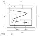
また本実施の形態においては、図10に示すように開口部12及び封止部13を設けてもよい。開口部12が設けられる場合は潜熱蓄熱材5の流路10Cが形成される。
(実施例4)
図11に本実施の形態における実施例として寸法の一例を示す。保冷具10は、外寸として短辺1A(1A’)の長さを220mm、長辺1B(1C)の長さを380mmとし、短辺1Aの一部に設けられた開口部8の長さを70mmとした。
図11に本実施の形態における実施例として寸法の一例を示す。保冷具10は、外寸として短辺1A(1A’)の長さを220mm、長辺1B(1C)の長さを380mmとし、短辺1Aの一部に設けられた開口部8の長さを70mmとした。
外部シール部6は、短辺1Aにおける線幅を10mm、長辺1B(1C)における線幅を短辺1A側10mm、短辺1A’側20mmとした。内部シール部11は線長を270mmとし、線幅を5mmとし、短辺1A(1A’)において内部シール部11Aと11Bとは平行であって内部シール部11Aと11Bとの距離は60mmとし、それぞれの内部シール部11は短辺1A(1A’)の端から70mmの箇所に形成されている。また流路10Cの幅は60mm~70mmとなる。
本実施例は目視では変形があまり確認できず、実施例1と同程度の変形といえる。
(実施例1~4の効果の検証)
実施例1~4及び比較例1を用いて本願発明の一態様の効果を検証した。検証に際して、保冷具1,10を平面に置いた際の形状の変化を正面変形度とし式(1)で表し、保冷具1,10を壁に立て掛けた際の形状の変化を側面変形度とし式(2)で表す。なお本願発明の一態様において潜熱蓄熱材5は液相状態で変形の検証を行う。


実施例1~4及び比較例1を用いて本願発明の一態様の効果を検証した。検証に際して、保冷具1,10を平面に置いた際の形状の変化を正面変形度とし式(1)で表し、保冷具1,10を壁に立て掛けた際の形状の変化を側面変形度とし式(2)で表す。なお本願発明の一態様において潜熱蓄熱材5は液相状態で変形の検証を行う。
ここで、正面とは例えば図2のようにフィルム2,3の面が見えていることを指し、側面とは例えば図3のようにフィルム2,3が横向きとなっており、面が見えていないことを指す。また投影面積は、保冷具1,10から一定の距離となる定点から撮影した写真から求めることができる。別の方法として、投影面積は、保冷具1,10と方眼紙のマス目とを比較することでも求めることができる。
以下に実施例1~4及び比較例1の立て掛け可否、正面変形度及び側面変形度の表を示す。

表1の実施例1と実施例2とからわかるように、内部シール部7が形成されている前提では、フィルム2,3の膜厚が100μmを超えると、保冷具1の変形は極めて少ないことがわかる。なお実施例1と比較例1とからわかるように内部シール部7が形成されていない場合は立て掛けができず正面変形度や側面変形度の比較すらできない。
また表1の実施例1と実施例3とからわかるように収容部4の体積(1200ml)に見合った潜熱蓄熱材5を充填することで、収容部4のすべての領域に潜熱蓄熱材5が充填され収容部4の変形が少なくなる。
[第3の実施の形態]
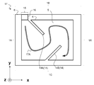
第1及び第2の実施の形態においては、保冷具1の長辺(1B,1C)又は短辺(1A,1A’)と内部シール部7とのなす角が略直角の場合について述べたが、図12に示すように保冷具17の長辺1B,1Cと内部シール部14(14A,14B)とのなす角は直角以外の角度でもよい。図12に示すように本実施の形態における保冷具17においては、内部シール部14(14A,14B)が収容部4の一対の向き合う辺(短辺1A,1A’)の内側に向かって延伸する。
第1及び第2の実施の形態においては、保冷具1の長辺(1B,1C)又は短辺(1A,1A’)と内部シール部7とのなす角が略直角の場合について述べたが、図12に示すように保冷具17の長辺1B,1Cと内部シール部14(14A,14B)とのなす角は直角以外の角度でもよい。図12に示すように本実施の形態における保冷具17においては、内部シール部14(14A,14B)が収容部4の一対の向き合う辺(短辺1A,1A’)の内側に向かって延伸する。
本実施の形態による保冷具17を、短辺(1A,1A’)を底にして壁に立て掛けると、図8に示した第2の実施の形態と同様に膨らみ制限部10A,10Bが2つ形成される。このため本実施の形態においても第1及び第2の実施の形態と同様に保冷具17における潜熱蓄熱材5の自重による収容部4の膨らみを制限することが可能となり、収容部4に収容される潜熱蓄熱材5の面内の充填密度の均一性を増すことができる。
本実施の形態においては、内部シール部14を斜め方向に形成するため直角方向に形成する場合である第1及び第2の実施の形態と比較すると、内部シール部14の線長を長くすることができ、保冷具17を壁に立て掛け易くすることができる。
さらに、内部シール部14を斜め方向に形成することで、図12におけるx軸方向及びy軸方向から、保冷具17外部より力が加わった場合において、液相状態の潜熱蓄熱材5が流動することにより受ける内部シール部14の応力が緩和され、耐衝撃性が増すことができる。そのため、例えば保冷具17のx軸方向又はy軸方向からの落下衝撃に対して耐性を増すことができる。
なお本実施の形態においては、図12に示すように開口部15及び封止部16を設けてもよい。開口部15が設けられる場合は潜熱蓄熱材5の流路17Aが形成される。
また本実施の形態においては、内部シール部14を斜め方向に形成するため直角方向に形成する場合である第1及び第2の実施の形態と比較すると、流路17Aを広く形成することが可能となり、必要以上に流路17Aを狭めることが少なくなる。流路17Aが広ければ、潜熱蓄熱材5の充填速度は速くなり保冷具17の生産性は高くなる。
(実施例5)
図13に本実施の形態における実施例として寸法の一例を示す。保冷具17は、外寸として短辺1A(1A’)の長さを150mm、長辺1B(1C)の長さを210mmとし、長辺1Bの一部に設けられた開口部8の長さを20mmとした。外部シール部6は、線幅を10mmとした。
図13に本実施の形態における実施例として寸法の一例を示す。保冷具17は、外寸として短辺1A(1A’)の長さを150mm、長辺1B(1C)の長さを210mmとし、長辺1Bの一部に設けられた開口部8の長さを20mmとした。外部シール部6は、線幅を10mmとした。
内部シール部14(14A,14B)は線長を85mmとし、線幅を5mmとした。内部シール部14Aは、長辺1Bの開口部15に隣接するように形成され、長辺1Bとのなす角を45°とした。内部シール部14Bは、長辺1Cの短辺1A側の端部から80mm(短辺1A’側の端部から110mm)の箇所を端として形成され長辺1Cとのなす角を45°とした。また流路17Aの幅は30mm~120mmとなる。また本実施例における保冷具17の外寸に合わせ充填する潜熱蓄熱材5の量は200gとした。なお、本実施例における流路17Aの幅は、内部シール部14を起点とする垂線を想定し、この垂線が流路17Aと交差し、且つ最も近い内部シール部14又は外部シール部6までの距離とした。
(実施例6)
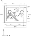
図14に本実施の形態における実施例として寸法の一例を示す。保冷具18は、外寸として短辺1A(1A’)の長さを245mm、長辺1B(1C)の長さを370mmとし、短辺1A(1A’)の一部に設けられた開口部18Fの長さを150mmとした。外部シール部6は、短辺1A(1A’)における線幅を15mmとし、長辺1B(1C)における線幅を20mmとした。内部シール部18A,18B,18C,18Dは、それぞれ線長を、190mm、125mm、70mm、70mmとし、線幅を5mmとした。
図14に本実施の形態における実施例として寸法の一例を示す。保冷具18は、外寸として短辺1A(1A’)の長さを245mm、長辺1B(1C)の長さを370mmとし、短辺1A(1A’)の一部に設けられた開口部18Fの長さを150mmとした。外部シール部6は、短辺1A(1A’)における線幅を15mmとし、長辺1B(1C)における線幅を20mmとした。内部シール部18A,18B,18C,18Dは、それぞれ線長を、190mm、125mm、70mm、70mmとし、線幅を5mmとした。
内部シール部18A,18Bは、長辺1C,1Bを端とし形成され、長辺1C,1Bとのなす角45°とした。また、内部シール部18C,Dは、短辺1A,1A’を端とし形成され、短辺1A,1A’とのなす角45°とした。また流路18Eの幅は40mm~150mmとなる。また本実施例における保冷具18の外寸に合わせ充填する潜熱蓄熱材5の量は1200gとした。なお、本実施例における流路18Eの幅は、内部シール部18A,18Bを起点とする垂線を想定し、この垂線が流路18Eと交差し、且つ隣接する内部シール部18A,18B又は外部シール部6までの距離とした。
[第4の実施の形態]
第1~第3の実施の形態においては、主に保冷具1,10,17,18について述べたが、図15に示すように物流梱包容器20が保冷具1(10,17,18)を備えていてもよい。
第1~第3の実施の形態においては、主に保冷具1,10,17,18について述べたが、図15に示すように物流梱包容器20が保冷具1(10,17,18)を備えていてもよい。
物流梱包容器20においては、保冷する対象である青果物などの保冷対象物21の上に設置された保冷具1(10,17,18)が容器20Cに収容される。容器20Cは、保冷具1(10,17,18)及び保冷対象物21を合わせた寸法よりも内寸が大きい。また容器20Cは断熱ボックスなどであって断熱効果を有している。
物流梱包容器20は、その内部において、保冷具1(10,17,18)を保冷対象物21の上に直接被覆することで、熱伝導を利用して保冷対象物21を直接保冷する。
従来は容器20Cの上部20A及び下部20Bに一般的な保冷具を設置することで内部の空間全体を保冷していた。これに対して本実施の形態による物流梱包容器20は、第1~第3の実施の形態の保冷具1(10,17,18)の充填密度が均一であるために、直接覆いかぶせた際に保冷対象物21と均一に接触することが可能となり保冷効率がよくなる。保冷対象物21の下は容器20Cの下部20Bと接触しているため保冷対象物21からの熱量の移動が少なくなっている。
なお保冷対象物21を輸送する際には、まず保冷対象物21の上に保冷具1を被覆し、保冷具1が上に設置された保冷対象物21を、保冷具1及び保冷対象物21を合わせた寸法よりも内寸が大きい容器20Cに収容する。
(実施例7)
まず容器20Cに収容する保冷具1の潜熱蓄熱材5としてテトラブチルアンモニウムの40wt%水溶液に過冷却抑制剤の炭酸カルシウムを1%添加した材料(20℃における密度1.036g)を用い、潜熱蓄熱材5の融点を12℃とした。この他の点に関しては実施例1と同様とした。
まず容器20Cに収容する保冷具1の潜熱蓄熱材5としてテトラブチルアンモニウムの40wt%水溶液に過冷却抑制剤の炭酸カルシウムを1%添加した材料(20℃における密度1.036g)を用い、潜熱蓄熱材5の融点を12℃とした。この他の点に関しては実施例1と同様とした。
次に保冷具1を3℃の保冷庫内において図4に示すように長辺1Cを底辺として壁に立て掛けて16時間静置することで潜熱蓄熱材5を凍結させた。この際の正面変形度及び側面変形度は0.1以下であってほとんど変形が見られなかった。
次に図15に示すように、保冷具1をロボットアームなどのロボットを使用し保冷対象物21に被覆し容器20Cに収容した。なお保冷具1が変形せずに均等になっているため、ロボットで保冷具1をつかみやすく、ロボットが保冷具1をつかむ際の微調整などに余計な時間がかからない。
次に物流梱包容器20を温度可変機能付恒温室に12時間静置し、恒温室内の温度を30℃~40℃の間で推移させ、真夏の輸送環境を模擬した。
(比較例2)
本実施の形態の比較例として、保冷具1の代わりに実施例7と同じ潜熱蓄熱材5を400ml充填した硬質容器(ブロー容器)を3つ用意し、容器20Cの内部の空間を冷却するように設置した。潜熱蓄熱材5の合計体積は実施例7と同様の1200mlとし、硬質容器は、1つは下部20Bに設置し、2つは容器20Cのふたなどに引っ掛けて並べて上部20Aに設置した。
本実施の形態の比較例として、保冷具1の代わりに実施例7と同じ潜熱蓄熱材5を400ml充填した硬質容器(ブロー容器)を3つ用意し、容器20Cの内部の空間を冷却するように設置した。潜熱蓄熱材5の合計体積は実施例7と同様の1200mlとし、硬質容器は、1つは下部20Bに設置し、2つは容器20Cのふたなどに引っ掛けて並べて上部20Aに設置した。
(実施例7の効果の検証)
図16に恒温室内、実施例7の保冷対象物21及び比較例2の保冷対象物21の経時による温度変化のグラフを示す。グラフ22は、恒温室内の経時による温度変化を示し、グラフ23は、比較例2の保冷対象物21の経時による温度変化を示し、グラフ24は、実施例7の保冷対象物21の経時による温度変化を示す。
図16に恒温室内、実施例7の保冷対象物21及び比較例2の保冷対象物21の経時による温度変化のグラフを示す。グラフ22は、恒温室内の経時による温度変化を示し、グラフ23は、比較例2の保冷対象物21の経時による温度変化を示し、グラフ24は、実施例7の保冷対象物21の経時による温度変化を示す。
グラフ23が示すように比較例2では2時間経過後あたりから保冷対象物21の温度が15℃を超えてしまう。これは比較例2のような硬質容器の配置では、上部の硬質容器と保冷対象物21との間に空間があり、容器20Cの外部からの熱流入により、温度が上昇し易いためである。
一方で、グラフ24が示すように実施例7によると12時間経過後も保冷対象物21の温度を15℃以下に保つことができる。これは、実施例7の保冷具1での保冷では、保冷対象物21を被覆し保冷対象物21と保冷具1との空間が少なくなり、保冷具1が備える潜熱蓄熱材5の融点である12℃付近にて保冷することができるためである。さらに、本実施の形態の保冷具1は、立掛けた状態で凍結した場合にも形状の変化が小さく、潜熱蓄熱材5の充填密度の均一が高いため、保冷対象物21全体を被覆して保冷することができる。
[他の実施の形態]
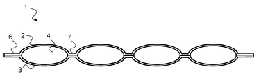
外部シール部6は、潜熱蓄熱材5の漏洩を防ぐために収容部4の周縁すべてを取り囲んでもよいが、図17の変形例の保冷具30に示すように1つのフィルム31を折り返して使用し外部シール部32が収容部33の外周の一部分に貼付される構成としてもよい。
外部シール部6は、潜熱蓄熱材5の漏洩を防ぐために収容部4の周縁すべてを取り囲んでもよいが、図17の変形例の保冷具30に示すように1つのフィルム31を折り返して使用し外部シール部32が収容部33の外周の一部分に貼付される構成としてもよい。
潜熱蓄熱材5の漏洩を防ぐために1つのフィルム31を折り返して使用する場合においても収容部33の外周を取り囲むように外部シール部32が貼付されてもよい。
また保冷具1,10,17,18におけるフィルム2,3の面は矩形だが、本願発明の一態様はこれに限らず例えば円形や楕円形でもよいものとする。また、保冷具1,10,17,18は矩形だが、角部が曲率半径を有した丸みを持った形状であってもよく、これにより保冷具1,10,17,18の取扱い安全性が増すことができる。
Claims (11)
- 互いに向かい合わせたフィルムから形成され、内部に潜熱蓄熱材が充填される収容部と、
前記収容部の周縁に貼付し潜熱蓄熱材の漏洩を防ぐ線状の外部シール部と、
前記収容部の内側に向かって延伸し、前記収容部の前記内部の上面及び下面を接着する線状の1又は複数の内部シール部と、を備える、
保冷具。 - 前記フィルムの膜厚100μm以上200μm以下である、
請求項1に記載の保冷具。 - 前記内部シール部は、前記収容部の一対の向き合う長辺の内部に向かって延伸する、
請求項1又は2に記載の保冷具。 - 前記潜熱蓄熱材は、主剤に水、又は、無機塩若しくは有機塩の水溶液を用いる、
請求項1~3のいずれか一項に記載の保冷具。 - 隣り合う一対の前記内部シール部が、前記収容部の一対の向き合う辺のそれぞれから内側に向かってそれぞれ延伸し、前記収容部の一対の向き合う辺に対して平行方向で前記保冷具を貫通する線を想定すると、隣り合う一対の内部シール部が前記貫通する線と交差する、請求項1~4のいずれか一項に記載の保冷具。
- 隣り合う一対の前記内部シール部が、前記収容部の一対の向き合う辺のそれぞれから内側に向かってそれぞれ延伸し、前記収容部の一対の向き合う辺の中央付近で近接し、前記内部シール部及び前記外部シール部によって区切られる前記潜熱蓄熱材の流路が所定の幅となる、
請求項1~5のいずれか一項に記載の保冷具。 - 前記外部シール部に設けられた開口部と、
前記開口部を覆う封止部と、をさらに備え、
前記封止部は前記内部シール部によって形成される前記潜熱蓄熱材の前記流路の一端である、
請求項6に記載の保冷具。 - 前記外部シール部が、前記収容部の周縁をすべて取り囲み、前記外部シール部の線幅が前記内部シール部の線幅よりも太い、
請求項1~7のいずれか一項に記載の保冷具。 - 請求項1~8のいずれか一項に記載の保冷具を備え、
前記保冷具は保冷する保冷対象物の上に覆いかぶされ、
前記保冷対象物を収容する、
物流梱包容器。 - 互いに向かい合わせたフィルムから形成され、内部に潜熱蓄熱材が充填される収容部と、前記収容部の周縁に貼付し潜熱蓄熱材の漏洩を防ぐ線状の外部シール部と、前記収容部の内側に向かって延伸し、前記収容部の前記内部の上面及び下面を接着する線状の1又は複数の内部シール部とを備える保冷具によって保冷する保冷対象物の輸送方法であって、
前記保冷対象物の上に前記保冷具を被覆する第1の工程と、
前記保冷対象物を収容する第2の工程と、を備える、
保冷対象物の輸送方法。 - 互いに向かい合わせたフィルムから形成され、内部に潜熱蓄熱材が充填される収容部と、前記収容部の周縁に貼付し潜熱蓄熱材の漏洩を防ぐ線状の外部シール部と、前記収容部の内側に向かって延伸し、前記収容部の前記内部の上面及び下面を接着する線状の1又は複数の内部シール部とを備える保冷具の製造方法であって、
前記潜熱蓄熱材を調製する第1の工程と、
前記外部シール部及び前記収容部を使用し、前記外部シール部に開口部が設けられた袋状の形状を作製する第2の工程と、
前記内部シール部を形成する第3の工程と、
前記開口部から前記潜熱蓄熱材を充填する第4の工程と、
前記開口部を封止する封止部を形成する第5の工程と、を備える、
保冷具の製造方法。
Priority Applications (3)
| Application Number | Priority Date | Filing Date | Title |
|---|---|---|---|
| US17/256,188 US20210270514A1 (en) | 2018-06-29 | 2019-05-27 | Cold storage pack, logistic packaging container, method of transporting object at low temperature, and method of manufacturing cold storage pack |
| CN201980042901.8A CN112334722A (zh) | 2018-06-29 | 2019-05-27 | 保冷具、物流包装容器、保冷对象物的输送方法以及保冷具的制造方法 |
| JP2020527294A JPWO2020003844A1 (ja) | 2018-06-29 | 2019-05-27 | 保冷具、物流梱包容器、保冷対象物の輸送方法及び保冷具の製造方法 |
Applications Claiming Priority (2)
| Application Number | Priority Date | Filing Date | Title |
|---|---|---|---|
| JP2018-125107 | 2018-06-29 | ||
| JP2018125107 | 2018-06-29 |
Publications (1)
| Publication Number | Publication Date |
|---|---|
| WO2020003844A1 true WO2020003844A1 (ja) | 2020-01-02 |
Family
ID=68986424
Family Applications (1)
| Application Number | Title | Priority Date | Filing Date |
|---|---|---|---|
| PCT/JP2019/020834 Ceased WO2020003844A1 (ja) | 2018-06-29 | 2019-05-27 | 保冷具、物流梱包容器、保冷対象物の輸送方法及び保冷具の製造方法 |
Country Status (4)
| Country | Link |
|---|---|
| US (1) | US20210270514A1 (ja) |
| JP (1) | JPWO2020003844A1 (ja) |
| CN (1) | CN112334722A (ja) |
| WO (1) | WO2020003844A1 (ja) |
Cited By (2)
| Publication number | Priority date | Publication date | Assignee | Title |
|---|---|---|---|---|
| JP2020006971A (ja) * | 2018-07-04 | 2020-01-16 | 藤森工業株式会社 | 液状体容器および液状体パック |
| JP2022022810A (ja) * | 2020-07-07 | 2022-02-07 | 東邦瓦斯株式会社 | 採暖用具及び採暖用具蓄熱方法 |
Citations (5)
| Publication number | Priority date | Publication date | Assignee | Title |
|---|---|---|---|---|
| JPS58177770U (ja) * | 1982-05-21 | 1983-11-28 | 積水化成品工業株式会社 | 蓄冷材用袋 |
| JPH0210096A (ja) * | 1988-06-29 | 1990-01-12 | Fujitsu Ltd | 潜熱蓄熱材 |
| JP2001330351A (ja) * | 2000-05-22 | 2001-11-30 | Mitsubishi Cable Ind Ltd | 複合蓄冷体およびその使用方法 |
| JP2013119392A (ja) * | 2011-12-06 | 2013-06-17 | Marui Hoso Shizai:Kk | 保冷具 |
| JP2013152064A (ja) * | 2012-01-26 | 2013-08-08 | Jfe Engineering Corp | 蓄熱体、その単位構造体及び蓄熱体の製造方法そして蓄熱体を有する蓄熱装置 |
Family Cites Families (1)
| Publication number | Priority date | Publication date | Assignee | Title |
|---|---|---|---|---|
| JP2012161516A (ja) * | 2011-02-08 | 2012-08-30 | Hirakawa Corporation | マット状保冷具 |
-
2019
- 2019-05-27 WO PCT/JP2019/020834 patent/WO2020003844A1/ja not_active Ceased
- 2019-05-27 JP JP2020527294A patent/JPWO2020003844A1/ja active Pending
- 2019-05-27 US US17/256,188 patent/US20210270514A1/en not_active Abandoned
- 2019-05-27 CN CN201980042901.8A patent/CN112334722A/zh active Pending
Patent Citations (5)
| Publication number | Priority date | Publication date | Assignee | Title |
|---|---|---|---|---|
| JPS58177770U (ja) * | 1982-05-21 | 1983-11-28 | 積水化成品工業株式会社 | 蓄冷材用袋 |
| JPH0210096A (ja) * | 1988-06-29 | 1990-01-12 | Fujitsu Ltd | 潜熱蓄熱材 |
| JP2001330351A (ja) * | 2000-05-22 | 2001-11-30 | Mitsubishi Cable Ind Ltd | 複合蓄冷体およびその使用方法 |
| JP2013119392A (ja) * | 2011-12-06 | 2013-06-17 | Marui Hoso Shizai:Kk | 保冷具 |
| JP2013152064A (ja) * | 2012-01-26 | 2013-08-08 | Jfe Engineering Corp | 蓄熱体、その単位構造体及び蓄熱体の製造方法そして蓄熱体を有する蓄熱装置 |
Cited By (2)
| Publication number | Priority date | Publication date | Assignee | Title |
|---|---|---|---|---|
| JP2020006971A (ja) * | 2018-07-04 | 2020-01-16 | 藤森工業株式会社 | 液状体容器および液状体パック |
| JP2022022810A (ja) * | 2020-07-07 | 2022-02-07 | 東邦瓦斯株式会社 | 採暖用具及び採暖用具蓄熱方法 |
Also Published As
| Publication number | Publication date |
|---|---|
| CN112334722A (zh) | 2021-02-05 |
| JPWO2020003844A1 (ja) | 2021-07-08 |
| US20210270514A1 (en) | 2021-09-02 |
Similar Documents
| Publication | Publication Date | Title |
|---|---|---|
| US11518602B2 (en) | Thermally insulated container | |
| US10919683B2 (en) | Thermal energy storage pack, thermal exchange unit, and manufacturing method of thermal energy storage pack | |
| JP2009184690A (ja) | 自立袋 | |
| US20170349356A1 (en) | Shipping container with multiple temperature zones | |
| US20170153054A1 (en) | Cold insulation member | |
| WO2020003844A1 (ja) | 保冷具、物流梱包容器、保冷対象物の輸送方法及び保冷具の製造方法 | |
| WO2019235279A1 (ja) | 保冷具および梱包容器、ならびに保冷対象物の輸送方法 | |
| US11912489B2 (en) | Package accommodating heat dissipation substrate and packing box | |
| JP2015169372A (ja) | 断熱容器および断熱容器の製造方法 | |
| JP2011140342A (ja) | エアパッキング部材、エアパッキング付き梱包箱および、エアパッキングシステム | |
| JP5286868B2 (ja) | 自立性容器 | |
| WO2019230627A1 (ja) | 梱包容器、保冷対象物の輸送方法 | |
| JP2014136593A (ja) | 保冷包装体、及び梱包体 | |
| WO2017211257A9 (zh) | 保温包装系统及保温包装装置和包装方法 | |
| CN206691431U (zh) | 一次性冰淇淋包装装置 | |
| CN107298254A (zh) | 气液复合保冷箱 | |
| WO2020235481A1 (ja) | 輸送容器及び収容方法 | |
| CN205045217U (zh) | 蓄冷包装袋 | |
| US20080034788A1 (en) | Temperature control pack and method | |
| JP7345310B2 (ja) | 内容物入りサイドガゼット袋用カートン、及び内容物入りサイドガゼット袋のカートン収納体 | |
| JP6897020B2 (ja) | 包装袋 | |
| WO2021059888A1 (ja) | 保冷具 | |
| CN107416361A (zh) | 冷链用轻型保冷箱 | |
| JP2008120418A (ja) | シャーベット状または粒状氷用の包装袋、それを用いた封入方法および包装体 | |
| CN107585442A (zh) | 蓄冷包装袋 |
Legal Events
| Date | Code | Title | Description |
|---|---|---|---|
| 121 | Ep: the epo has been informed by wipo that ep was designated in this application |
Ref document number: 19826056 Country of ref document: EP Kind code of ref document: A1 |
|
| ENP | Entry into the national phase |
Ref document number: 2020527294 Country of ref document: JP Kind code of ref document: A |
|
| NENP | Non-entry into the national phase |
Ref country code: DE |
|
| 122 | Ep: pct application non-entry in european phase |
Ref document number: 19826056 Country of ref document: EP Kind code of ref document: A1 |