WO2020003775A1 - Dispositif de détection, appareil de gestion de dispositif pour des dispositifs de détection, procédé de sélection de dispositif et procédé de gestion de dispositif - Google Patents
Dispositif de détection, appareil de gestion de dispositif pour des dispositifs de détection, procédé de sélection de dispositif et procédé de gestion de dispositif Download PDFInfo
- Publication number
- WO2020003775A1 WO2020003775A1 PCT/JP2019/018960 JP2019018960W WO2020003775A1 WO 2020003775 A1 WO2020003775 A1 WO 2020003775A1 JP 2019018960 W JP2019018960 W JP 2019018960W WO 2020003775 A1 WO2020003775 A1 WO 2020003775A1
- Authority
- WO
- WIPO (PCT)
- Prior art keywords
- selection
- sensing device
- state
- sensing
- unit
- Prior art date
Links
- 238000007726 management method Methods 0.000 title description 52
- 238000010187 selection method Methods 0.000 title 1
- 238000005259 measurement Methods 0.000 claims abstract description 35
- 238000000034 method Methods 0.000 claims description 20
- 230000008859 change Effects 0.000 claims description 19
- 230000007704 transition Effects 0.000 claims description 13
- 230000003287 optical effect Effects 0.000 claims description 6
- 230000000694 effects Effects 0.000 abstract description 20
- 238000005516 engineering process Methods 0.000 description 45
- 238000010586 diagram Methods 0.000 description 28
- 238000004891 communication Methods 0.000 description 10
- 238000012545 processing Methods 0.000 description 9
- 230000004048 modification Effects 0.000 description 5
- 238000012986 modification Methods 0.000 description 5
- 230000007246 mechanism Effects 0.000 description 4
- 230000001678 irradiating effect Effects 0.000 description 3
- 230000008569 process Effects 0.000 description 3
- 230000004044 response Effects 0.000 description 2
- 238000001514 detection method Methods 0.000 description 1
- 238000009434 installation Methods 0.000 description 1
- 230000001151 other effect Effects 0.000 description 1
- 230000002265 prevention Effects 0.000 description 1
- 238000003672 processing method Methods 0.000 description 1
- 230000007480 spreading Effects 0.000 description 1
Images


Classifications
-
- G—PHYSICS
- G08—SIGNALLING
- G08C—TRANSMISSION SYSTEMS FOR MEASURED VALUES, CONTROL OR SIMILAR SIGNALS
- G08C17/00—Arrangements for transmitting signals characterised by the use of a wireless electrical link
- G08C17/02—Arrangements for transmitting signals characterised by the use of a wireless electrical link using a radio link
-
- H—ELECTRICITY
- H04—ELECTRIC COMMUNICATION TECHNIQUE
- H04Q—SELECTING
- H04Q9/00—Arrangements in telecontrol or telemetry systems for selectively calling a substation from a main station, in which substation desired apparatus is selected for applying a control signal thereto or for obtaining measured values therefrom
-
- G—PHYSICS
- G01—MEASURING; TESTING
- G01H—MEASUREMENT OF MECHANICAL VIBRATIONS OR ULTRASONIC, SONIC OR INFRASONIC WAVES
- G01H17/00—Measuring mechanical vibrations or ultrasonic, sonic or infrasonic waves, not provided for in the preceding groups
-
- G—PHYSICS
- G01—MEASURING; TESTING
- G01J—MEASUREMENT OF INTENSITY, VELOCITY, SPECTRAL CONTENT, POLARISATION, PHASE OR PULSE CHARACTERISTICS OF INFRARED, VISIBLE OR ULTRAVIOLET LIGHT; COLORIMETRY; RADIATION PYROMETRY
- G01J3/00—Spectrometry; Spectrophotometry; Monochromators; Measuring colours
- G01J3/28—Investigating the spectrum
-
- H—ELECTRICITY
- H04—ELECTRIC COMMUNICATION TECHNIQUE
- H04L—TRANSMISSION OF DIGITAL INFORMATION, e.g. TELEGRAPHIC COMMUNICATION
- H04L67/00—Network arrangements or protocols for supporting network services or applications
- H04L67/01—Protocols
- H04L67/12—Protocols specially adapted for proprietary or special-purpose networking environments, e.g. medical networks, sensor networks, networks in vehicles or remote metering networks
-
- H—ELECTRICITY
- H04—ELECTRIC COMMUNICATION TECHNIQUE
- H04Q—SELECTING
- H04Q9/00—Arrangements in telecontrol or telemetry systems for selectively calling a substation from a main station, in which substation desired apparatus is selected for applying a control signal thereto or for obtaining measured values therefrom
- H04Q9/02—Automatically-operated arrangements
-
- H—ELECTRICITY
- H04—ELECTRIC COMMUNICATION TECHNIQUE
- H04M—TELEPHONIC COMMUNICATION
- H04M11/00—Telephonic communication systems specially adapted for combination with other electrical systems
- H04M11/04—Telephonic communication systems specially adapted for combination with other electrical systems with alarm systems, e.g. fire, police or burglar alarm systems
-
- H—ELECTRICITY
- H04—ELECTRIC COMMUNICATION TECHNIQUE
- H04Q—SELECTING
- H04Q2209/00—Arrangements in telecontrol or telemetry systems
- H04Q2209/40—Arrangements in telecontrol or telemetry systems using a wireless architecture
-
- H—ELECTRICITY
- H04—ELECTRIC COMMUNICATION TECHNIQUE
- H04Q—SELECTING
- H04Q2209/00—Arrangements in telecontrol or telemetry systems
- H04Q2209/70—Arrangements in the main station, i.e. central controller
- H04Q2209/75—Arrangements in the main station, i.e. central controller by polling or interrogating the sub-stations
-
- H—ELECTRICITY
- H04—ELECTRIC COMMUNICATION TECHNIQUE
- H04Q—SELECTING
- H04Q2209/00—Arrangements in telecontrol or telemetry systems
- H04Q2209/80—Arrangements in the sub-station, i.e. sensing device
- H04Q2209/82—Arrangements in the sub-station, i.e. sensing device where the sensing device takes the initiative of sending data
-
- H—ELECTRICITY
- H04—ELECTRIC COMMUNICATION TECHNIQUE
- H04Q—SELECTING
- H04Q2209/00—Arrangements in telecontrol or telemetry systems
- H04Q2209/80—Arrangements in the sub-station, i.e. sensing device
- H04Q2209/84—Measuring functions
-
- H—ELECTRICITY
- H04—ELECTRIC COMMUNICATION TECHNIQUE
- H04Q—SELECTING
- H04Q2209/00—Arrangements in telecontrol or telemetry systems
- H04Q2209/80—Arrangements in the sub-station, i.e. sensing device
- H04Q2209/88—Providing power supply at the sub-station
- H04Q2209/883—Providing power supply at the sub-station where the sensing device enters an active or inactive mode
Definitions
- This technology relates to sensing devices. More specifically, the present invention relates to a sensing device including a sensor, a device management apparatus for the device, and a processing method in the device.
- IoT devices having a wireless communication function are rapidly spreading.
- a disaster prevention system including a plurality of terminals that perform observation by a sensor and transmit the observed sensor information by wireless communication, and a control device that predicts a disaster based on the sensor information has been proposed (for example, see Patent Document 1).
- a plurality of terminals (IoT devices) having a sensor function are installed to collect sensor information.
- IoT devices terminals
- management of each IoT device becomes complicated. For example, when moving after installing an IoT device, flexible management is required.
- This technology has been created in view of such a situation, and aims to flexibly manage devices in an installed state and appropriately control them.
- a first aspect of the present technology is to provide a sensor that measures a surrounding environment to generate a measurement signal, and a sensing device that measures the measurement signal according to the measurement signal.
- a sensing device including a selection control unit that controls a selection state, and a notification unit that notifies that the sensing device is selected when the selection state indicates that the sensing device is selected, and a method of selecting the same. This brings about the effect that the sensing device is selected according to the measurement signal of the sensor, and the effect is notified.
- the notification unit may further notify identification information for identifying the sensing device in the notification. This brings about the effect of identifying the selected sensing device in the apparatus that has been notified.
- the identification information may include a device type of the sensing device. Accordingly, an effect is provided that the device type of the selected sensing device is identified in the notified device.
- the identification information may include a group to which the sensing device belongs.
- the identification information may include a group to which the sensing device belongs.
- the selection control unit transitions the selection state to indicate that the sensing device is selected when the measurement signal indicates selection of the sensing device.
- the selection state may be changed to indicate that the sensing device has not been selected. This brings about an effect of selecting or canceling the selection of the sensing device according to the measurement signal of the sensor.
- the first aspect may further include a selection state information holding unit that holds the selection state. This brings about the effect of maintaining the selected state in the sensing device.
- the apparatus further comprises a selection reception state holding unit that holds a selection reception state indicating whether or not the sensing device can receive the change instruction of the selection state, wherein the selection control unit receives the change instruction.
- the selection state may be changed only when the selection accepting state indicates that the selection is possible. This brings about the effect of improving the security of selection.
- the first aspect may further include a selection receiving state changing unit that changes the selection receiving state according to an external instruction. This brings about the effect of externally controlling whether or not selection can be accepted.
- the senor may be an optical sensor, and may receive the light of a predetermined wavelength and generate the measurement signal indicating that the selection of the sensing device has been instructed. This brings about the effect of selecting a sensing device using light.
- the senor may be a vibration sensor, and may generate the measurement signal indicating that the selection of the sensing device has been instructed when receiving a vibration of a predetermined frequency. This brings about the effect that the sensing device is selected using the vibration.
- a second aspect of the present technology includes a device selection instructing unit that instructs at least a part of a plurality of sensing devices each having a sensor to select the sensing device by a signal that can be measured by the sensor,
- a device management apparatus comprising: a device selection notification receiving unit that receives a notification from the selected sensing device among a plurality of sensing devices; and a management control unit that manages information about the selected sensing device based on the notification. And its device management method. This brings about the effect that the sensor of the sensing device selects the sensing device based on the measurable signal and receives a notification from the sensing device.
- the notification may include the identification information of the selected sensing device, and the management control unit may manage the identification information of the selected sensing device. This brings about the effect of identifying the selected sensing device.
- the device may further include a device list holding unit that holds information on the selected sensing device. This brings about an effect of flexibly managing the selected sensing device.
- FIG. 1 is a diagram illustrating an example of an overall configuration of a sensing system according to an embodiment of the present technology.
- 1 is a diagram illustrating an example of a configuration of an IoT device 100 according to an embodiment of the present technology.
- 1 is a diagram illustrating an example of a configuration of a device management device 200 according to an embodiment of the present technology.
- FIG. 4 is a diagram illustrating an example of a field configuration of a device list held in a device list holding unit 240 according to the embodiment of the present technology.
- 5 is a flowchart illustrating an example of a processing procedure of the IoT device 100 according to the embodiment of the present technology.
- 13 is a flowchart illustrating an example of a processing procedure of the device management apparatus 200 according to the embodiment of the present technology.
- FIG. 7 is a sequence diagram illustrating an example of overall processing of the sensing system according to the embodiment of the present technology.
- FIG. 13 is a sequence diagram illustrating a modification of the entire processing of the sensing system according to the embodiment of the present technology.
- FIG. 1 is a diagram illustrating a specific example of a plurality of IoT devices 100 and a device management apparatus 200 according to an embodiment of the present technology.
- FIG. 14 is a diagram illustrating an example of a selection instruction using a light as the device selection instruction unit 220 according to the embodiment of the present technology.
- FIG. 14 is a diagram illustrating an example of a selection release instruction using a light as the device selection instruction unit 220 according to the embodiment of the present technology.
- FIG. 14 is a diagram illustrating an example of a group A selection instruction using a light as the device selection instruction unit 220 according to the embodiment of the present technology.
- FIG. 14 is a diagram illustrating an example of a group B selection instruction using a light as the device selection instruction unit 220 according to the embodiment of the present technology.
- Fig. 3 is a diagram illustrating an example in which different types of IoT devices are mixed and arranged in the embodiment of the present technology.
- FIG. 11 is a diagram illustrating an example of a selection instruction by irradiating red light from a device selection instruction unit 220 according to an embodiment of the present technology.
- FIG. 13 is a diagram illustrating an example of a selection instruction by irradiating blue light from a device selection instruction unit 220 according to an embodiment of the present technology.
- FIG. 1 is a diagram illustrating an example of an overall configuration of a sensing system according to an embodiment of the present technology.
- This sensing system includes a plurality of IoT devices 100, a device management device 200, a base station 300, and a server 500.
- the IoT device 100 and the base station 300 are connected by wireless communication.
- the base station 300 and the server 500 are connected via a network 400.
- the IoT device 100 is a sensing device having a wireless communication function and a sensor function. This IoT device 100 transmits the measurement result of the sensor by wireless communication.
- the IoT device 100 is an example of the sensing device described in the claims.
- the base station 300 is a base station that performs wireless communication with the IoT device 100.
- the base station 300 performs wireless communication with the IoT device 100 installed in the communication range 301.
- the base station 300 connects to the server 500 via the network 400 and transmits a measurement result from the IoT device 100 to the server 500.
- the server 500 is a server that holds the measurement results from the IoT device 100.
- the server 500 connects the IoT device 100 via the network 400, and receives and holds a measurement result from the IoT device 100.
- the device management device 200 manages the IoT device 100. As will be described later, the device management apparatus 200 instructs selection or deselection of the IoT device 100, receives a notification from the IoT device 100, and creates a device list for managing the IoT device 100 based on the notification. I do.
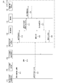
- FIG. 2 is a diagram illustrating an example of a configuration of the IoT device 100 according to the embodiment of the present technology.
- the IoT device 100 includes a selection reception state changing unit 110, a selection reception state holding unit 120, a selection state information holding unit 130, a sensor 140, a selection control unit 150, an identification information holding unit 160, and a notification unit 170. And
- the selection reception status holding unit 120 holds a selection reception status indicating whether or not the IoT device 100 is receiving a change in the selection status.
- the selection accepting state holding unit 120 holds the “selectable state” when the change of the selection state is accepted, and holds the “selection impossible state” when the state of the selection state is not accepted. .
- the selection receiving state changing unit 110 changes the selection receiving state stored in the selection receiving state holding unit 120.
- the selection accepting state is a concept provided from the viewpoint of security (secure).
- security secure
- When changing the selection state it is assumed that an authorized person sets in advance a "selectable state". .
- the function of the selection receiving state changing unit 110 may be realized by using a sensor 140 and a selection control unit 150 described later.
- the selection state information holding unit 130 holds selection state information indicating whether the IoT device 100 is in a selected state.
- the selection state information holding unit 130 holds a “selected state” when the state is selected, and holds a “non-selected state” when the state is not selected.
- the sensor 140 measures the surrounding environment by a detection (sensing) operation and generates a measurement signal.
- the sensor 140 has a sensing function of measuring, for example, radio waves including visible light and infrared rays, sound waves, vibrations, and the like, and more specifically, an optical sensor, a vibration sensor, or the like is assumed.
- the sensor 140 has a function as a selection receiving unit. That is, the selection of the IoT device 100 is received using the sensor 140 having a normal sensing function without separately providing a special mechanism for receiving the selection of the IoT device 100. This simplifies the configuration of the IoT device 100 and contributes to power saving.
- the sensor 140 may receive not only an instruction for selection but also an instruction for release of selection.
- the selection control unit 150 controls the selection state of the IoT device 100.
- the selection control unit 150 causes the selection state information held in the selection state information holding unit 130 to transition to the “selected state”.
- the selected state information held in the selected state information holding unit 130 is changed to the “non-selected state”.
- the selection reception state held in the selection reception state holding unit 120 indicates “selection disabled state”
- the selection state information cannot be changed.
- the selection accepting state may be changed to the “selection impossible state”.
- the identification information holding unit 160 holds identification information for identifying the IoT device 100.
- As the identification information a device unique identifier uniquely assigned to uniquely identify the IoT device 100, a device type identifier representing the type (device type) of the IoT device 100, and the like are assumed.
- the notifying unit 170 notifies the device management apparatus 200 that the IoT device 100 has been selected when the selection state information held in the selection state information holding unit 130 is “selected state”.
- the notification unit 170 has, for example, a wireless communication function, and transmits a notification to the device management apparatus 200 by wireless communication.
- the notification unit 170 also notifies the identification information of the IoT device 100. Accordingly, the device management apparatus 200 can grasp information on the selected IoT device 100.
- FIG. 3 is a diagram illustrating an example of a configuration of the device management device 200 according to the embodiment of the present technology.
- the device management apparatus 200 includes a selection accepting state change instruction unit 210, a device selection instruction unit 220, a device selection notification receiving unit 230, a device list holding unit 240, and a management control unit 250.
- the selection acceptance state change instructing unit 210 instructs at least a part of the plurality of IoT devices 100 to change the selection acceptance state. This instruction is received by the selection reception state changing unit 110 of the IoT device 100, and the selection reception state held in the selection reception state holding unit 120 is changed accordingly.
- the selection reception state is provided from the viewpoint of security, and in an environment where security is ensured by another method, the secure mechanism by the selection reception state change instruction unit 210 is not provided. You may. Further, in this embodiment, an example in which the device management apparatus 200 includes the selection reception state change instruction unit 210 will be described. However, the selection reception state may be changed by a device different from the device management apparatus 200.
- the device selection instructing unit 220 instructs at least a part of the plurality of IoT devices 100 to select the IoT device 100.
- This instruction is detected by the sensor 140 of the IoT device 100, and the selection state information stored in the selection state information storage unit 130 is set by the selection control unit 150 according to the measurement signal. Therefore, it is assumed that the instruction by the device selection instruction unit 220 uses, for example, radio waves including visible light and infrared light, sound waves, vibrations, and the like in accordance with the sensing function of the sensor 140.
- the device selection instructing unit 220 may instruct the IoT device 100 not only to select but also to cancel the selection.
- the device selection notification receiving unit 230 receives a notification from the IoT device 100 in response to the selection instruction.
- This notification is a notification performed by the notification unit 170 of the IoT device 100 when the selection status information of the IoT device 100 is “selected status”.
- This notification includes the identification information of the IoT device 100, so that the device management apparatus 200 can grasp the information on the selected IoT device 100.
- the management control unit 250 controls each unit of the device management apparatus 200. That is, the management control unit 250 controls an instruction to change the selection acceptance state of the IoT device 100, an instruction to select the IoT device 100, and the like.
- the device list holding unit 240 holds a device list that is a list of IoT devices 100 whose selection state information is “selected”.
- the device list is created by the management control unit 250 based on the notification received by the device selection notification receiving unit 230.
- FIG. 4 is a diagram showing an example of a field configuration of a device list held in the device list holding unit 240 according to the embodiment of the present technology.
- the device list includes fields of a format identifier 241, a device type identifier 242, a device unique identifier 243, a belonging group identifier 244, time information 245, and additional information 246.
- the format identifier 241 is information that can be recognized as identification information transmitted by the IoT device 100.
- the device type identifier 242 is information indicating the device type (device type) of the IoT device 100.
- the device unique identifier 243 is information that can uniquely specify the IoT device 100.
- a MAC (Media Access Control) address of a NIC (Network Interface Card) or a BD (Bluetooth Device) address of Bluetooth (registered trademark) can be used. Further, values obtained by converting these addresses according to a certain rule may be used.
- the belonging group identifier 244 is information indicating a group selected as the IoT device 100. That is, as described later, the IoT device 100 may be selected in a group unit, and in that case, the IoT device 100 may be selected across a plurality of groups. Therefore, it is assumed that a bit field corresponding to each group is provided, and selection or non-selection is expressed in binary for the group to which the IoT device 100 belongs.
- the time information 245 is information indicating the time at which the IoT device 100 was selected or the time at which the selection state changed.
- the additional information 246 is a field for storing other information, and is information that can be appropriately used by an application.
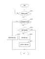
- FIG. 5 is a flowchart illustrating an example of a processing procedure of the IoT device 100 according to the embodiment of the present technology. In this example, it is assumed that the selection reception state stored in the selection reception state storage unit 120 is set in advance.
- the selection control unit 150 waits until the sensor 140 receives a selection instruction from the device selection instruction unit 220 of the device management apparatus 200 (step S911: No). When the selection instruction has been received (step S911: Yes), the selection control unit 150 performs the following selection operation. However, even when the selection instruction is received, when the selection release instruction is further received (step S912: Yes), the selection state information held in the selection state information holding unit 130 is set to “non-selection state”. (Step S916).
- step S912 When the selection cancellation instruction is not received (step S912: No), if the selection reception state held in the selection reception state holding unit 120 indicates “selectable state” (step S913: Yes), the selection state information is set to “ The selected state is set (step S914). Then, the notification unit 170 notifies the device management apparatus 200 that the IoT device 100 has been selected (Step S915). On the other hand, if the selection reception state held in the selection reception state holding unit 120 indicates “selection disabled state” (step S913: No), the process ends without changing the selection state information.
- FIG. 6 is a flowchart illustrating an example of a processing procedure of the device management apparatus 200 according to the embodiment of the present technology.
- the device selection instructing unit 220 instructs the IoT device 100 to be selected from among the plurality of IoT devices 100 to select the IoT device 100 (step S921). After that, the process waits until a notification to the effect that the device has been selected is received from the IoT device 100 instructing the selection (step S922: No).
- the management control unit 250 when receiving the notification of the selection from the IoT device 100 (step S922: Yes), the management control unit 250 creates a device list based on the notification and records it in the device list holding unit 240 (step S922). S923).
- FIG. 7 is a sequence diagram illustrating an example of an entire process of the sensing system according to the embodiment of the present technology.
- the selection accepting state change instructing unit 210 instructs the IoT device 100 to transition its selection accepting state to a “selectable state” (811).
- the selection receiving state changing unit 110 transitions the selection receiving state held in the selection receiving state holding unit 120 to the “selectable state” (812).
- the device selection instructing unit 220 instructs the IoT device 100 to select the IoT device 100 (813).
- the selection control unit 150 instructs the notification unit 170 to transition the selection state information held in the selection state information holding unit 130 to the “selection state” and notify that the selection has been made. (814). Accordingly, the notification unit 170 reads the identification information from the identification information holding unit 160 (815) and notifies the device management apparatus 200 (816).
- the selection accepting state change instructing unit 210 instructs the IoT device 100 to transition the selection accepting state to the “selection impossible state” (821).
- the selection receiving state changing unit 110 changes the selection receiving state held in the selection receiving state holding unit 120 to the “selection disabled state” (829).
- FIG. 8 is a sequence diagram illustrating a modification of the entire processing of the sensing system according to the embodiment of the present technology.
- the notification unit 170 notifies the selection.
- the identification information may be notified periodically.
- the selection information may be stored immediately after notifying the identification information, and notified at a predetermined timing.
- notification is made at the timing when the selection reception ends and the selection reception state transitions to the “selection disabled state”.
- the selection accepting state change instructing unit 210 instructs the IoT device 100 to transition the selection accepting state to the “selectable state” (811). After that, until the notifying unit 170 reads the identification information from the identification information holding unit 160 (815), it is the same as the above-described example.
- the selection accepting state change instructing unit 210 instructs the IoT device 100 to transition the selection accepting state to the “selection impossible state” (821), and the selection control unit 150 is notified of this. (822), a notification is made at this timing. That is, the notifying unit 170 notifies the device management apparatus 200 of the identification information (815) read from the identification information holding unit 160 (823). Then, the selection accepting state changing unit 110 changes the selection accepting state held in the selection accepting state holding unit 120 to the “selection impossible state” (829).
- FIG. 9 is a diagram illustrating a specific example of the plurality of IoT devices 100 and the device management apparatus 200 according to the embodiment of the present technology.
- the sensor 140 of the IoT device 100 is an optical sensor
- a light that emits visible light is used as the device selection instruction unit 220.
- the IoT according to the purpose depends on the visible light irradiation range. It becomes possible to select a device group. In the following example, it is assumed that the selection acceptance state of the IoT device 100 is “selectable state”.
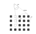
- FIG. 10 is a diagram illustrating an example of a selection instruction using a light as the device selection instruction unit 220 according to the embodiment of the present technology.
- visible light for instructing selection is emitted from the device selection instructing unit 220, and visible light is radiated to some regions 221 of the plurality of IoT devices 100.
- the selection state information of the IoT device 101 existing in the area 221 transitions to “selection state”.
- FIG. 11 is a diagram illustrating an example of a selection release instruction using a light as the device selection instruction unit 220 according to the embodiment of the present technology.
- visible light for instructing deselection is emitted from the device selection instructing unit 220, and visible light is applied to some of the regions 222 of the plurality of IoT devices 100.
- the selected state information of the IoT device 102 existing in the area 222 transits to “non-selected state”.
- the selected state information of the IoT device 101 that is present in the area 221 and not present in the area 222 becomes “selected state”, and the identification information is notified at a predetermined timing thereafter.
- the IoT device 100 may be selected on a group basis. In this case, the IoT device 100 may be selected across a plurality of groups.
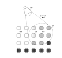
- FIG. 12 is a diagram illustrating an example of a group A selection instruction using a light as the device selection instruction unit 220 according to the embodiment of the present technology.
- visible light for instructing selection of group A is emitted from the device selection instructing unit 220, and visible light is applied to a partial region 223 of the plurality of IoT devices 100.
- the selection state information of the IoT device 103 existing in the area 223 transits to “selection state” as the group A.
- FIG. 13 is a diagram illustrating an example of a group B selection instruction using a light as the device selection instruction unit 220 according to the embodiment of the present technology.
- the visible light for instructing the selection of the group B is emitted from the device selection instructing unit 220, and the visible light is applied to a partial area 224 of the plurality of IoT devices 100.
- the visible light instructing the selection of the group B is different from the visible light instructing the selection of the group A.
- the selection state information of the IoT device 104 existing in the area 224 transits to “selection state” as the group B.
- the IoT device 105 existing in the area 224 and already selected as the group A is selected across the group A and the group B.
- the group to which each of the IoT devices 103 to 105 belongs is notified by its own notification unit 170.
- the management control unit 250 of the device management apparatus 200 that has received the notification stores the group identifier 244 of the device list in the device list holding unit 240 as a bit field corresponding to each group. Thereby, the device management apparatus 200 can manage the IoT devices 100 for each group.
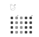
- FIG. 14 is a diagram illustrating an example in which different types of IoT devices are mixed and arranged in the embodiment of the present technology.
- an IoT device 106 that recognizes selection when irradiated with red light and an IoT device 107 that recognizes selection when irradiated with blue light are arranged in a mixed manner.
- the selection can be made with visible light of different wavelengths, it is possible to select an IoT device group according to the purpose.
- FIG. 15 is a diagram illustrating an example of a selection instruction by emitting red light from the device selection instruction unit 220 according to the embodiment of the present technology.
- the IoT device 106 since the red light is emitted from the device selection instruction unit 220, the IoT device 106 recognizes that the IoT device 106 has been selected. As a result, the selected state information of the IoT device 106 transits to “selected state”.
- FIG. 16 is a diagram illustrating an example of a selection instruction by irradiating blue light from the device selection instruction unit 220 according to the embodiment of the present technology.
- the IoT device 107 since blue light is emitted from the device selection instruction unit 220, the IoT device 107 recognizes that it has been selected. As a result, the selection state information of the IoT device 107 transits to “selection state”.
- the selection and deselection operations have been described assuming that an optical sensor is used as the sensor 140.
- the sensor 140 may be another type of sensor.
- selection and deselection may be performed in response to the sound of applause.
- the selection of the IoT device 100 using the sensor 140 having the normal sensing function (without separately providing a special mechanism for receiving the selection of the IoT device 100). And its release).
- the selected IoT device 100 notifies the device management apparatus 200 of the identification information by the notification unit 170.
- the device management apparatus 200 can generate a device list of the IoT device 100 in a state where the IoT device 100 is installed. In other words, there is no need to create and manage a management ledger for each IoT device 100 before operation, and even if the IoT device 100 is moved after the start of operation, flexible management is possible in the latest installation state. It can be performed.
- the processing procedure described in the above embodiment may be considered as a method having a series of these procedures, and a program for causing a computer to execute the series of procedures or a recording medium for storing the program. May be caught.
- a recording medium for example, a CD (Compact Disc), an MD (MiniDisc), a DVD (Digital Versatile Disc), a memory card, a Blu-ray Disc (Blu-ray (registered trademark) Disc), or the like can be used.
- the present technology may have the following configurations.
- a sensor that measures a surrounding environment and generates a measurement signal;
- a selection control unit that controls a selection state of the sensing device in accordance with the measurement signal,
- a sensing unit that, when the selected state indicates that the sensing device is selected, notifies the user of the selection.
- the notification unit further notifies identification information for identifying the sensing device in the notification.
- the identification information includes a device type of the sensing device.
- the identification information includes a group to which the sensing device belongs.
- the selection control unit transitions the selection state so as to indicate that the sensing device is selected, and the measurement signal is The sensing device according to any one of (1) to (4), wherein when the instruction to cancel the selection of the sensing device is issued, the selection state is changed to indicate that the sensing device is not selected.
- a selection reception state holding unit that holds a selection reception state indicating whether or not the sensing device can receive the change instruction of the selection state
- the selection control unit changes the selection state only when the selection reception state indicates that a change instruction can be received.
- Sensing device (11) a device selection instructing unit that instructs at least a part of a plurality of sensing devices each having a sensor to select the sensing device by a signal measurable by the sensor; A device selection notification receiving unit that receives a notification from the selected sensing device among the plurality of sensing devices, A device management device comprising: a management control unit that manages information on the selected sensing device based on the notification.
- the notification includes identification information of the selected sensing device,
- (14) a procedure in which the sensor of the sensing device measures the surrounding environment and generates a measurement signal; A procedure in which a selection control unit controls a selection state of the sensing device according to the measurement signal, A step of, when the selected state indicates that the sensing device has been selected, a notifying unit notifying the selection state; (15) a step in which the device selection instructing unit instructs at least a part of the plurality of sensing devices each having a sensor to select the sensing device by a signal measurable by the sensor; A procedure in which a device selection notification receiving unit receives a notification from the selected sensing device among the plurality of sensing devices, A management control unit for managing information on the selected sensing device based on the notification.
- IoT device 100 to 107 IoT device 110 Selection accepting state changing unit 120 Selection accepting state holding unit 130 Selection state information holding unit 140 Sensor 150 Selection control unit 160 Identification information holding unit 170 Notification unit 200 Device management device 210 Selection accepting state change instructing unit 220 Device Selection instructing unit 230 device selection notification receiving unit 240 device list holding unit 241 format identifier 242 device type identifier 243 device unique identifier 244 belonging group identifier 245 time information 246 additional information 250 management control unit 300 base station 400 network 500 server
Landscapes
- Engineering & Computer Science (AREA)
- Physics & Mathematics (AREA)
- Computer Networks & Wireless Communication (AREA)
- General Physics & Mathematics (AREA)
- Spectroscopy & Molecular Physics (AREA)
- Computing Systems (AREA)
- Health & Medical Sciences (AREA)
- General Health & Medical Sciences (AREA)
- Medical Informatics (AREA)
- Signal Processing (AREA)
- Selective Calling Equipment (AREA)
- Alarm Systems (AREA)
- Arrangements For Transmission Of Measured Signals (AREA)
Abstract
La présente invention gère de manière flexible des dispositifs de détection qui sont installés, et commande de manière appropriée ces dispositifs de détection. Les dispositifs de détection selon la présente invention comportent chacun un capteur, une unité de commande de sélection et une unité de notification. Le capteur mesure l'environnement ambiant et génère un signal de mesure. L'unité de commande de sélection commande un état de sélection dudit dispositif de détection en fonction du signal de mesure fourni par le capteur. Lorsque l'état de sélection indique que ledit dispositif de détection est sélectionné, l'unité de notification donne une notification à cet effet.
Priority Applications (2)
| Application Number | Priority Date | Filing Date | Title |
|---|---|---|---|
| DE112019003275.5T DE112019003275T5 (de) | 2018-06-29 | 2019-05-13 | Erfassungsvorrichtung, vorrichtungsverwaltungseinrichtung für erfassungsvorrichtungen, vorrichtungsauswahlverfahren, und vorrichtungsverwaltungsverfahren |
| US17/250,236 US11935399B2 (en) | 2018-06-29 | 2019-05-13 | Sensing device, device management apparatus for sensing device, device selecting method, and device managing method |
Applications Claiming Priority (2)
| Application Number | Priority Date | Filing Date | Title |
|---|---|---|---|
| JP2018123949 | 2018-06-29 | ||
| JP2018-123949 | 2018-06-29 |
Publications (1)
| Publication Number | Publication Date |
|---|---|
| WO2020003775A1 true WO2020003775A1 (fr) | 2020-01-02 |
Family
ID=68986309
Family Applications (1)
| Application Number | Title | Priority Date | Filing Date |
|---|---|---|---|
| PCT/JP2019/018960 WO2020003775A1 (fr) | 2018-06-29 | 2019-05-13 | Dispositif de détection, appareil de gestion de dispositif pour des dispositifs de détection, procédé de sélection de dispositif et procédé de gestion de dispositif |
Country Status (3)
| Country | Link |
|---|---|
| US (1) | US11935399B2 (fr) |
| DE (1) | DE112019003275T5 (fr) |
| WO (1) | WO2020003775A1 (fr) |
Families Citing this family (1)
| Publication number | Priority date | Publication date | Assignee | Title |
|---|---|---|---|---|
| JP7392407B2 (ja) * | 2019-11-14 | 2023-12-06 | 株式会社デンソー | センター装置、車両用電子制御システム、プログラム更新の進捗制御方法及びプログラム更新の進捗制御プログラム |
Citations (2)
| Publication number | Priority date | Publication date | Assignee | Title |
|---|---|---|---|---|
| JP2011120151A (ja) * | 2009-12-07 | 2011-06-16 | Hitachi Ltd | 無線通信装置、無線通信装置の制御方法、及び無線通信装置を用いたセンサネットシステム |
| JP2015087864A (ja) * | 2013-10-29 | 2015-05-07 | セコム株式会社 | 通信システム |
Family Cites Families (9)
| Publication number | Priority date | Publication date | Assignee | Title |
|---|---|---|---|---|
| JP5569051B2 (ja) * | 2010-03-11 | 2014-08-13 | オムロンヘルスケア株式会社 | 生体情報測定装置、生体情報管理システムおよび生体情報管理方法 |
| US9882915B2 (en) * | 2012-08-07 | 2018-01-30 | Panasonic Intellectual Property Management Co., Ltd. | Device control method, device control system |
| JP6078900B2 (ja) * | 2012-09-10 | 2017-02-15 | パナソニックIpマネジメント株式会社 | 機器管理装置 |
| US9134794B2 (en) * | 2013-08-20 | 2015-09-15 | Kabushiki Kaisha Toshiba | System to identify user and device the user is intending to operate |
| JP6528409B2 (ja) * | 2015-01-13 | 2019-06-12 | 日本電気株式会社 | 対象表示システム、管理装置、対象表示方法及び管理プログラム |
| US9659484B1 (en) * | 2015-11-02 | 2017-05-23 | Rapidsos, Inc. | Method and system for situational awareness for emergency response |
| JP2017091440A (ja) | 2015-11-17 | 2017-05-25 | ソニー株式会社 | 防災システム及び防災方法 |
| KR102638748B1 (ko) * | 2015-12-04 | 2024-02-20 | 삼성전자 주식회사 | 적어도 하나의 센서를 이용한 기기 관리 방법 및 장치 |
| US10732037B1 (en) * | 2018-03-01 | 2020-08-04 | Photon Systems, Inc. | Methods and apparatus for spectroscopic identification and/or calibrated quantification of surface concentration of materials |
-
2019
- 2019-05-13 US US17/250,236 patent/US11935399B2/en active Active
- 2019-05-13 WO PCT/JP2019/018960 patent/WO2020003775A1/fr active Application Filing
- 2019-05-13 DE DE112019003275.5T patent/DE112019003275T5/de not_active Withdrawn
Patent Citations (2)
| Publication number | Priority date | Publication date | Assignee | Title |
|---|---|---|---|---|
| JP2011120151A (ja) * | 2009-12-07 | 2011-06-16 | Hitachi Ltd | 無線通信装置、無線通信装置の制御方法、及び無線通信装置を用いたセンサネットシステム |
| JP2015087864A (ja) * | 2013-10-29 | 2015-05-07 | セコム株式会社 | 通信システム |
Also Published As
| Publication number | Publication date |
|---|---|
| DE112019003275T5 (de) | 2021-04-08 |
| US20210174667A1 (en) | 2021-06-10 |
| US11935399B2 (en) | 2024-03-19 |
Similar Documents
| Publication | Publication Date | Title |
|---|---|---|
| JP4634476B2 (ja) | 光記録情報保存媒体、記録/再生方法、記録/再生装置 | |
| CN107636666A (zh) | 用于控制对于计算设备上的应用的准许请求的方法和系统 | |
| JP2017123634A (ja) | 画像出力装置、携帯情報処理装置、画像出力システム、画像読取装置、画像読取システム、画像出力プログラム、情報処理プログラム及び画像読取プログラム | |
| WO2020003775A1 (fr) | Dispositif de détection, appareil de gestion de dispositif pour des dispositifs de détection, procédé de sélection de dispositif et procédé de gestion de dispositif | |
| JP2017037451A (ja) | 情報処理装置及び情報処理プログラム | |
| CN103180837A (zh) | 设定系统、服务器、终端设备、设定方法和设定程序 | |
| US20120251124A1 (en) | Transceiver for different vendor devices | |
| CN106241504A (zh) | 脚位移控制立式绕线机的方法及系统 | |
| JP2017123145A (ja) | 携帯情報処理装置、画像出力システム及び情報処理プログラム | |
| CN112769849B (zh) | 一种病毒确诊与阻断的方法、系统、设备及存储介质 | |
| KR102402853B1 (ko) | 스탠드얼론 자동실행 및 스탠드얼론 동시실행 서비스 제공 장치 및 그 방법 | |
| KR100667811B1 (ko) | Rds 데이터 보안 장치 및 방법 | |
| JP2014182689A (ja) | 情報処理装置及び情報処理プログラム | |
| CN106241503A (zh) | 基于压力的立式绕线机控制方法及系统 | |
| JP6798366B2 (ja) | 情報処理システム、画像形成装置と端末装置とが通信するための方法、および画像形成装置 | |
| WO2023157251A1 (fr) | Dispositif de traitement, système de traitement, procédé de traitement, programme et support de stockage | |
| WO2017159781A1 (fr) | Dispositif de gestion d'étiquette, procédé de gestion d'étiquette et programme | |
| JP2010176352A (ja) | 非接触通信装置、非接触通信システム、非接触通信方法およびプログラム | |
| US20170063612A1 (en) | Information processing apparatus, information processing system, and recording medium | |
| JP2022175394A (ja) | 管理装置及び管理方法 | |
| CN106276415A (zh) | 卧式绕线机的脚转动方法及系统 | |
| CN106249630A (zh) | 卧式绕线机的位移控制方法及系统 | |
| JP2017199215A (ja) | コンテンツ配信装置、コンテンツ配信システム及びプログラム | |
| JP5181742B2 (ja) | 情報処理装置及び情報処理プログラム | |
| JP2018082222A (ja) | 中継装置、方法およびプログラム |
Legal Events
| Date | Code | Title | Description |
|---|---|---|---|
| 121 | Ep: the epo has been informed by wipo that ep was designated in this application |
Ref document number: 19826801 Country of ref document: EP Kind code of ref document: A1 |
|
| 122 | Ep: pct application non-entry in european phase |
Ref document number: 19826801 Country of ref document: EP Kind code of ref document: A1 |
|
| NENP | Non-entry into the national phase |
Ref country code: JP |