WO2020003693A1 - Battery temperature adjustment device and control device - Google Patents
Battery temperature adjustment device and control device Download PDFInfo
- Publication number
- WO2020003693A1 WO2020003693A1 PCT/JP2019/015761 JP2019015761W WO2020003693A1 WO 2020003693 A1 WO2020003693 A1 WO 2020003693A1 JP 2019015761 W JP2019015761 W JP 2019015761W WO 2020003693 A1 WO2020003693 A1 WO 2020003693A1
- Authority
- WO
- WIPO (PCT)
- Prior art keywords
- battery
- temperature
- battery pack
- control device
- packs
- Prior art date
Links
Images


Classifications
-
- H—ELECTRICITY
- H01—ELECTRIC ELEMENTS
- H01M—PROCESSES OR MEANS, e.g. BATTERIES, FOR THE DIRECT CONVERSION OF CHEMICAL ENERGY INTO ELECTRICAL ENERGY
- H01M50/00—Constructional details or processes of manufacture of the non-active parts of electrochemical cells other than fuel cells, e.g. hybrid cells
- H01M50/20—Mountings; Secondary casings or frames; Racks, modules or packs; Suspension devices; Shock absorbers; Transport or carrying devices; Holders
- H01M50/204—Racks, modules or packs for multiple batteries or multiple cells
-
- B—PERFORMING OPERATIONS; TRANSPORTING
- B60—VEHICLES IN GENERAL
- B60K—ARRANGEMENT OR MOUNTING OF PROPULSION UNITS OR OF TRANSMISSIONS IN VEHICLES; ARRANGEMENT OR MOUNTING OF PLURAL DIVERSE PRIME-MOVERS IN VEHICLES; AUXILIARY DRIVES FOR VEHICLES; INSTRUMENTATION OR DASHBOARDS FOR VEHICLES; ARRANGEMENTS IN CONNECTION WITH COOLING, AIR INTAKE, GAS EXHAUST OR FUEL SUPPLY OF PROPULSION UNITS IN VEHICLES
- B60K1/00—Arrangement or mounting of electrical propulsion units
- B60K1/04—Arrangement or mounting of electrical propulsion units of the electric storage means for propulsion
-
- B—PERFORMING OPERATIONS; TRANSPORTING
- B60—VEHICLES IN GENERAL
- B60K—ARRANGEMENT OR MOUNTING OF PROPULSION UNITS OR OF TRANSMISSIONS IN VEHICLES; ARRANGEMENT OR MOUNTING OF PLURAL DIVERSE PRIME-MOVERS IN VEHICLES; AUXILIARY DRIVES FOR VEHICLES; INSTRUMENTATION OR DASHBOARDS FOR VEHICLES; ARRANGEMENTS IN CONNECTION WITH COOLING, AIR INTAKE, GAS EXHAUST OR FUEL SUPPLY OF PROPULSION UNITS IN VEHICLES
- B60K11/00—Arrangement in connection with cooling of propulsion units
- B60K11/02—Arrangement in connection with cooling of propulsion units with liquid cooling
- B60K11/04—Arrangement or mounting of radiators, radiator shutters, or radiator blinds
-
- H—ELECTRICITY
- H01—ELECTRIC ELEMENTS
- H01M—PROCESSES OR MEANS, e.g. BATTERIES, FOR THE DIRECT CONVERSION OF CHEMICAL ENERGY INTO ELECTRICAL ENERGY
- H01M10/00—Secondary cells; Manufacture thereof
- H01M10/60—Heating or cooling; Temperature control
- H01M10/61—Types of temperature control
- H01M10/613—Cooling or keeping cold
-
- H—ELECTRICITY
- H01—ELECTRIC ELEMENTS
- H01M—PROCESSES OR MEANS, e.g. BATTERIES, FOR THE DIRECT CONVERSION OF CHEMICAL ENERGY INTO ELECTRICAL ENERGY
- H01M10/00—Secondary cells; Manufacture thereof
- H01M10/60—Heating or cooling; Temperature control
- H01M10/61—Types of temperature control
- H01M10/615—Heating or keeping warm
-
- H—ELECTRICITY
- H01—ELECTRIC ELEMENTS
- H01M—PROCESSES OR MEANS, e.g. BATTERIES, FOR THE DIRECT CONVERSION OF CHEMICAL ENERGY INTO ELECTRICAL ENERGY
- H01M10/00—Secondary cells; Manufacture thereof
- H01M10/60—Heating or cooling; Temperature control
- H01M10/62—Heating or cooling; Temperature control specially adapted for specific applications
- H01M10/625—Vehicles
-
- H—ELECTRICITY
- H01—ELECTRIC ELEMENTS
- H01M—PROCESSES OR MEANS, e.g. BATTERIES, FOR THE DIRECT CONVERSION OF CHEMICAL ENERGY INTO ELECTRICAL ENERGY
- H01M10/00—Secondary cells; Manufacture thereof
- H01M10/60—Heating or cooling; Temperature control
- H01M10/63—Control systems
- H01M10/633—Control systems characterised by algorithms, flow charts, software details or the like
-
- H—ELECTRICITY
- H01—ELECTRIC ELEMENTS
- H01M—PROCESSES OR MEANS, e.g. BATTERIES, FOR THE DIRECT CONVERSION OF CHEMICAL ENERGY INTO ELECTRICAL ENERGY
- H01M10/00—Secondary cells; Manufacture thereof
- H01M10/60—Heating or cooling; Temperature control
- H01M10/65—Means for temperature control structurally associated with the cells
- H01M10/655—Solid structures for heat exchange or heat conduction
- H01M10/6556—Solid parts with flow channel passages or pipes for heat exchange
-
- H—ELECTRICITY
- H01—ELECTRIC ELEMENTS
- H01M—PROCESSES OR MEANS, e.g. BATTERIES, FOR THE DIRECT CONVERSION OF CHEMICAL ENERGY INTO ELECTRICAL ENERGY
- H01M10/00—Secondary cells; Manufacture thereof
- H01M10/60—Heating or cooling; Temperature control
- H01M10/65—Means for temperature control structurally associated with the cells
- H01M10/656—Means for temperature control structurally associated with the cells characterised by the type of heat-exchange fluid
- H01M10/6567—Liquids
- H01M10/6568—Liquids characterised by flow circuits, e.g. loops, located externally to the cells or cell casings
-
- H—ELECTRICITY
- H01—ELECTRIC ELEMENTS
- H01M—PROCESSES OR MEANS, e.g. BATTERIES, FOR THE DIRECT CONVERSION OF CHEMICAL ENERGY INTO ELECTRICAL ENERGY
- H01M10/00—Secondary cells; Manufacture thereof
- H01M10/60—Heating or cooling; Temperature control
- H01M10/65—Means for temperature control structurally associated with the cells
- H01M10/658—Means for temperature control structurally associated with the cells by thermal insulation or shielding
-
- H—ELECTRICITY
- H01—ELECTRIC ELEMENTS
- H01M—PROCESSES OR MEANS, e.g. BATTERIES, FOR THE DIRECT CONVERSION OF CHEMICAL ENERGY INTO ELECTRICAL ENERGY
- H01M10/00—Secondary cells; Manufacture thereof
- H01M10/60—Heating or cooling; Temperature control
- H01M10/65—Means for temperature control structurally associated with the cells
- H01M10/659—Means for temperature control structurally associated with the cells by heat storage or buffering, e.g. heat capacity or liquid-solid phase changes or transition
-
- B—PERFORMING OPERATIONS; TRANSPORTING
- B60—VEHICLES IN GENERAL
- B60L—PROPULSION OF ELECTRICALLY-PROPELLED VEHICLES; SUPPLYING ELECTRIC POWER FOR AUXILIARY EQUIPMENT OF ELECTRICALLY-PROPELLED VEHICLES; ELECTRODYNAMIC BRAKE SYSTEMS FOR VEHICLES IN GENERAL; MAGNETIC SUSPENSION OR LEVITATION FOR VEHICLES; MONITORING OPERATING VARIABLES OF ELECTRICALLY-PROPELLED VEHICLES; ELECTRIC SAFETY DEVICES FOR ELECTRICALLY-PROPELLED VEHICLES
- B60L53/00—Methods of charging batteries, specially adapted for electric vehicles; Charging stations or on-board charging equipment therefor; Exchange of energy storage elements in electric vehicles
-
- Y—GENERAL TAGGING OF NEW TECHNOLOGICAL DEVELOPMENTS; GENERAL TAGGING OF CROSS-SECTIONAL TECHNOLOGIES SPANNING OVER SEVERAL SECTIONS OF THE IPC; TECHNICAL SUBJECTS COVERED BY FORMER USPC CROSS-REFERENCE ART COLLECTIONS [XRACs] AND DIGESTS
- Y02—TECHNOLOGIES OR APPLICATIONS FOR MITIGATION OR ADAPTATION AGAINST CLIMATE CHANGE
- Y02E—REDUCTION OF GREENHOUSE GAS [GHG] EMISSIONS, RELATED TO ENERGY GENERATION, TRANSMISSION OR DISTRIBUTION
- Y02E60/00—Enabling technologies; Technologies with a potential or indirect contribution to GHG emissions mitigation
- Y02E60/10—Energy storage using batteries
-
- Y—GENERAL TAGGING OF NEW TECHNOLOGICAL DEVELOPMENTS; GENERAL TAGGING OF CROSS-SECTIONAL TECHNOLOGIES SPANNING OVER SEVERAL SECTIONS OF THE IPC; TECHNICAL SUBJECTS COVERED BY FORMER USPC CROSS-REFERENCE ART COLLECTIONS [XRACs] AND DIGESTS
- Y02—TECHNOLOGIES OR APPLICATIONS FOR MITIGATION OR ADAPTATION AGAINST CLIMATE CHANGE
- Y02T—CLIMATE CHANGE MITIGATION TECHNOLOGIES RELATED TO TRANSPORTATION
- Y02T10/00—Road transport of goods or passengers
- Y02T10/60—Other road transportation technologies with climate change mitigation effect
- Y02T10/70—Energy storage systems for electromobility, e.g. batteries
-
- Y—GENERAL TAGGING OF NEW TECHNOLOGICAL DEVELOPMENTS; GENERAL TAGGING OF CROSS-SECTIONAL TECHNOLOGIES SPANNING OVER SEVERAL SECTIONS OF THE IPC; TECHNICAL SUBJECTS COVERED BY FORMER USPC CROSS-REFERENCE ART COLLECTIONS [XRACs] AND DIGESTS
- Y02—TECHNOLOGIES OR APPLICATIONS FOR MITIGATION OR ADAPTATION AGAINST CLIMATE CHANGE
- Y02T—CLIMATE CHANGE MITIGATION TECHNOLOGIES RELATED TO TRANSPORTATION
- Y02T10/00—Road transport of goods or passengers
- Y02T10/60—Other road transportation technologies with climate change mitigation effect
- Y02T10/7072—Electromobility specific charging systems or methods for batteries, ultracapacitors, supercapacitors or double-layer capacitors
-
- Y—GENERAL TAGGING OF NEW TECHNOLOGICAL DEVELOPMENTS; GENERAL TAGGING OF CROSS-SECTIONAL TECHNOLOGIES SPANNING OVER SEVERAL SECTIONS OF THE IPC; TECHNICAL SUBJECTS COVERED BY FORMER USPC CROSS-REFERENCE ART COLLECTIONS [XRACs] AND DIGESTS
- Y02—TECHNOLOGIES OR APPLICATIONS FOR MITIGATION OR ADAPTATION AGAINST CLIMATE CHANGE
- Y02T—CLIMATE CHANGE MITIGATION TECHNOLOGIES RELATED TO TRANSPORTATION
- Y02T90/00—Enabling technologies or technologies with a potential or indirect contribution to GHG emissions mitigation
- Y02T90/10—Technologies relating to charging of electric vehicles
- Y02T90/14—Plug-in electric vehicles
Definitions
- the present disclosure relates to a battery temperature control device and a control device.
- Patent Document 1 a device in which a cooling circuit traversing the plurality of battery packs is formed has been proposed in, for example, Patent Document 1.
- the cooling circuit is arranged across the plurality of battery packs, it is possible to reduce temperature variations among the battery packs.
- the battery pack has a configuration including a battery module including a plurality of battery cells, a relay connected to the battery module, and a battery management system for monitoring each battery cell.
- One battery pack functions as a power supply.
- the present disclosure aims to provide a battery temperature control device and a control device that can cool or heat at least a part of a plurality of battery packs in a short time.
- a battery temperature control device is a device that adjusts the temperature of a secondary battery in which a plurality of chargeable / dischargeable battery packs are connected in parallel.
- the battery temperature controller includes a heat medium supply unit that supplies a heat medium to each of the plurality of battery packs independently.
- the battery temperature control device includes a control device.
- the control device defines the battery pack to be temperature-adjusted preferentially based on the battery state of the plurality of battery packs as a specific battery pack, and sets the supply ratio of the heat medium to the specific battery pack to be higher than that of other battery packs In order to increase the temperature, temperature adjustment control for controlling the heat medium supply unit is performed.
- the control device performs control for adjusting the temperature of the secondary battery in which a plurality of chargeable / dischargeable battery packs are connected in parallel.
- the control device independently increases the heating medium supply ratio for each of the plurality of battery packs so as to increase the supply ratio of the heating medium to the battery packs to be temperature-adjusted preferentially based on the battery states of the plurality of battery packs.
- Temperature control for controlling the heat medium supply unit that supplies the heat.
- the amount of heat exchange between the specific battery pack and the heat medium can be increased with priority over other battery packs. Therefore, the temperature of a specific battery pack can be adjusted before the other battery packs. Therefore, at least a part of the plurality of battery packs can be cooled or heated in a short time.
- FIG. 1 is a diagram showing a battery temperature control device according to the first embodiment
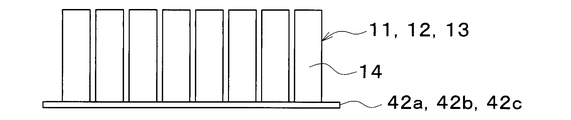
- FIG. 2 is a diagram showing a battery pack
- FIG. 3 is a diagram showing a first battery pack provided with a heat insulating material
- FIG. 4 is a diagram showing a first battery pack provided with a heat storage material
- FIG. 5 is a diagram showing a first battery pack provided with a heat insulating material and a heat storage material
- FIG. 6 is a diagram showing a temperature transition of the battery pack shown in FIGS. 2 to 5 in a cold region.
- FIG. 7 is a diagram for explaining a control device included in the battery temperature control device.
- FIG. 8 is a flowchart showing the content of temperature adjustment for each battery pack.
- FIG. 9 is a diagram for explaining heating of the first battery pack having the first priority.
- FIG. 10 is a diagram for explaining the heating of the second battery pack of the second priority.
- FIG. 11 is a diagram for explaining heating of the third battery pack having the third priority.
- FIG. 12 is a diagram showing a first battery pack according to the second embodiment
- FIG. 13 is a diagram showing a temperature transition of the battery pack shown in FIG. 12 in a cold region
- FIG. 14 is a diagram showing a battery temperature control device according to the third embodiment
- FIG. 15 is a view showing a modification of the secondary battery according to the third embodiment.
- the battery temperature controller 1 shown in FIG. 1 is a device that adjusts a secondary battery 10 mounted on a vehicle to an appropriate temperature. Further, the battery temperature control device 1 also functions as an air conditioner that adjusts the interior space of the vehicle to an appropriate temperature.
- the battery temperature controller 1 is mounted on an electric vehicle that obtains a driving force for driving the vehicle from an electric motor for driving.
- the electric vehicle can charge the secondary battery 10 mounted on the vehicle with electric power supplied from an external power supply when the vehicle stops.
- the external power supply is, for example, a commercial power supply.
- the electric power stored in the secondary battery 10 is supplied not only to the electric motor for traveling but also to various in-vehicle devices such as electric components constituting the battery temperature control device 1.
- the secondary battery 10 has first to third chargeable / dischargeable battery packs 11 to 13.
- Each of the battery packs 11 to 13 has a plurality of battery cells 14, a relay 15, and a battery management system (not shown).
- the battery management system is referred to as BMU.
- Each battery cell 14 is connected in series.
- a lithium ion battery can be used as each battery cell 14.
- the temperature of the battery of this type is low, the chemical reaction does not easily proceed, and sufficient performance regarding charge and discharge cannot be exhibited.
- this type of battery tends to deteriorate at high temperatures. Therefore, the temperature of each battery cell 14 is adjusted within a proper temperature range where sufficient performance can be exhibited.
- the relay 15 is connected to both ends of each of the battery packs 11 to 13. In the present embodiment, the relays 15 of all the battery packs 11 to 13 are energized. Further, the number of cells and the battery capacity of the battery cells 14 of each of the battery packs 11 to 13 are the same. Further, the battery packs 11 to 13 are connected in parallel.
- the BMU includes a voltage sensor for detecting the voltage of each battery cell 14, a current sensor for detecting the current flowing through the battery packs 11 to 13, and a temperature sensor for detecting the temperatures of the battery packs 11 to 13 and each battery cell 14.
- the battery packs 11 to 13 are arranged on battery flow paths 42a to 42c to be described later.
- each of the battery packs 11 to 13 can exchange heat with the heat medium flowing through the corresponding battery flow path 42a to 42c.
- the first battery pack 11 includes a heat insulating material 16, a heat storage material 17, or both the heat insulating material 16 and the heat storage material 17. As shown in FIG. 2, the other battery packs 12 and 13 do not have the heat insulating material 16 and the heat storage material 17.
- the heat insulating material 16 covers the first battery pack 11 to insulate heat released from the first battery pack 11.
- a material such as a vacuum heat insulating material, glass wool, or foamed polyurethane is used.
- the first battery pack 11 is thermally insulated from the external environment by the heat insulating material 16. Further, the first battery pack 11 has a small amount of heat radiation to the external environment and a small amount of heat absorption from the external environment due to the heat insulating material 16. That is, the first battery pack 11 has a smaller temperature change due to the exchange of heat with the outside than the other battery packs 12 and 13. In other words, the first battery pack 11 is unlikely to become hot or cold.
- the heat storage material 17 is disposed around the battery cells 14 in order to store the heat released from each battery cell 14.
- the heat storage material 17 stores heat using the phase transition of the material.
- the first battery pack 11 has a large apparent heat capacity, so that the temperature change with respect to the heat radiation amount and the heat absorption amount is smaller than that of the other battery packs 12 and 13.
- each of the battery packs 11 to 13 differs depending on the presence or absence of the heat insulating material 16 and the heat storage material 17.
- the normal battery pack that is, the other battery packs 12 and 13 falls below the predetermined temperature at the earliest.
- the temperature is increased in the order of the first battery pack 11 provided with the heat storage material 17, the first battery pack 11 provided with the heat insulating material 16, and the first battery pack 11 provided with both the heat storage material 17 and the heat insulating material 16. It is hard to fall.
- the first battery pack 11 having a relatively higher temperature than the other battery packs 12 and 13 is preferentially heated, the first battery pack 11 is moved to the earliest. A predetermined temperature can be reached. Further, in the second time in which the stop time is relatively long, the temperatures of all the battery packs 11 to 13 are the same. Therefore, the battery packs 11 to 13, which require the least amount of heat to heat to the predetermined temperature, may be preferentially heated. That is, the battery packs 11 to 13 which have a small heat capacity and a high heat insulation property may be preferentially heated. By such a temperature adjustment, it is possible to shorten the start-up time of the secondary battery 10 and reduce the battery warm-up energy. Similarly, when cooling each of the battery packs 11 to 13, the first priority may be preferentially cooled from among the battery packs 11 to 13. The temperature adjustment of each of the battery packs 11 to 13 will be described later in detail.
- each of the BMUs 11a, 12a, and 13a of each of the battery packs 11 to 13 outputs information on the voltage, current, and temperature detected by each sensor to the control device 70 as needed.
- the battery temperature controller 1 has a refrigeration cycle device 20. Hereinafter, each component of the refrigeration cycle device 20 will be described.
- the compressor 21 sucks, compresses, and discharges the refrigerant in the refrigeration cycle device 20.
- the compressor 21 is arranged in a vehicle hood.
- the compressor 21 is an electric compressor in which a fixed displacement compression mechanism having a fixed discharge capacity is rotationally driven by an electric motor.
- the rotation speed (that is, the refrigerant discharge capacity) of the compressor 21 is controlled by a control signal output from a control device 70 described later.
- the inlet of the refrigerant passage of the high-temperature water-refrigerant heat exchanger 22 is connected to the discharge port of the compressor 21.
- the high-temperature side water-refrigerant heat exchanger 22 exchanges heat between the high-pressure refrigerant discharged from the compressor 21 and the high-temperature side heat medium circulating in the high-temperature cooling water circuit 30 to heat the high-temperature side heat medium. It is.
- the high-temperature side heat medium a solution containing ethylene glycol, an antifreeze, or the like can be used.
- the high-temperature cooling water circuit 30 is a high-temperature-side water circuit that circulates the high-temperature-side heat medium.
- the high-temperature cooling water circuit 30 has a high-temperature side circulation channel 31.
- the high temperature side circulation channel 31 is a cooling water channel through which high temperature side cooling water as a high temperature side heat medium circulates.
- a water passage of the high temperature side water-refrigerant heat exchanger 22, a high temperature side radiator 32, a high temperature side pump 33, a high temperature side electric heater 34, a high temperature side heater core 35 and the like are arranged.
- the high-temperature side radiator 32 is arranged on the front side inside the vehicle hood.
- the high temperature side radiator 32 may be formed integrally with the high temperature side water-refrigerant heat exchanger 22 and the like.
- the high-temperature side radiator 32 exchanges heat between the high-temperature side heat medium heated by the high-temperature side water-refrigerant heat exchanger 22 and the outside air blown from an outside air fan (not shown) to remove the heat of the high-temperature side heat medium to the outside air.
- This is a heat exchanger that dissipates heat.
- the high temperature side pump 33 is a high temperature side water pump that pumps the high temperature side heat medium to the high temperature side electric heater 34 in the high temperature cooling water circuit 30.
- the high temperature side pump 33 is an electric pump whose rotation speed (that is, water pumping capacity) is controlled by a control voltage output from the control device 70.
- the high-temperature side electric heater 34 is an auxiliary heater that generates heat when supplied with electric power and heats the high-temperature side heat medium of the high-temperature cooling water circuit 30 that is pumped from the high-temperature side pump 33.
- the high-temperature side heater core 35 is disposed in an air-conditioning casing described later.
- the high-temperature side heater core 35 is a heat exchanger that heats the blown air by exchanging heat between the high-temperature side heat medium heated by the high-temperature side electric heater 34 and the blown air.
- the high-temperature side pump 33, the high-temperature side electric heater 34, the high-temperature side heater core 35, the high-temperature side water-refrigerant heat exchanger 22, and the like, which are discharged from the compressor 21, are arranged in the high-temperature cooling water circuit 30.
- a heating unit that heats the blown air using the cooled refrigerant as a heat source is configured.
- the high-temperature cooling water circuit 30 has a path connected in parallel to the high-temperature radiator 32.
- the path connected in parallel to the high-temperature radiator 32 is a bypass path that bypasses the high-temperature radiator 32.
- a thermostat valve (not shown) is provided at a junction between the bypass path and the path of the high-temperature radiator 32.
- the high-temperature heat medium flows through the path of the high-temperature radiator 32 or the bypass path in accordance with the temperature of the high-temperature heat medium of the high-temperature cooling water circuit 30.
- the branch portion 23a branches the flow of the refrigerant flowing out of the high-temperature side water-refrigerant heat exchanger 22.
- the branch portion 23a has a three-way joint structure having three inflow ports that communicate with each other. One of the three inflow ports is a refrigerant inlet, and the other two are refrigerant outlets.
- a receiver may be connected to the outlet of the refrigerant passage of the high temperature side water-refrigerant heat exchanger 22.
- the receiver separates the gas-liquid of the high-pressure refrigerant flowing out of the high-temperature-side water-refrigerant heat exchanger 22, causes the separated liquid-phase refrigerant to flow downstream, and stores the excess refrigerant in the cycle as the liquid-phase refrigerant. It is a separation unit.
- the receiver is a cylindrical container having a bottom. The receiver may be formed integrally with the high temperature side water-refrigerant heat exchanger 22 and the like.
- the inlet side of the cooling expansion valve 24a is connected to one outlet of the branch portion 23a.
- the inlet side of the heat-absorbing expansion valve 24b is connected to the other outlet of the branch portion 23a.
- the cooling expansion valve 24a is a pressure reducing unit that reduces the pressure of the refrigerant flowing out of the high-temperature side water-refrigerant heat exchanger 22 at least in the cooling mode and the dehumidifying / heating mode, and also controls the flow rate of the refrigerant flowing into the indoor evaporator 25. This is a cooling flow rate adjusting unit to be adjusted.
- the cooling expansion valve 24a is an electric type configured to include a valve body configured to change the degree of opening of the throttle and an electric actuator (specifically, a stepping motor) that changes the degree of opening of the valve body. Variable aperture mechanism. The operation of the cooling expansion valve 24a is controlled by a control signal (control pulse) output from the control device 70.
- the cooling expansion valve 24a has a fully closed function of closing the refrigerant passage by fully closing the valve opening.
- the refrigerant inlet side of the indoor evaporator 25 is connected to the outlet of the cooling expansion valve 24a.
- the indoor evaporator 25 is disposed in the air conditioning casing. More specifically, the indoor evaporator 25 is disposed on the upstream side of the blown air flow from the high temperature side heater core 35.
- the indoor evaporator 25 is used for cooling at least in the cooling mode and the dehumidifying / heating mode, in which the low-pressure refrigerant depressurized by the cooling expansion valve 24a and the blast air exchange heat to evaporate the low-pressure refrigerant and cool the blast air.
- the evaporator is used for cooling at least in the cooling mode and the dehumidifying / heating mode, in which the low-pressure refrigerant depressurized by the cooling expansion valve 24a and the blast air exchange heat to evaporate the low-pressure refrigerant and cool the blast air.
- the refrigerant outlet of the indoor evaporator 25 is connected to the inlet side of the evaporation pressure regulating valve 26.
- the evaporation pressure adjustment valve 26 is an evaporation pressure adjustment unit that maintains the refrigerant evaporation pressure in the indoor evaporator 25 at a predetermined reference pressure or higher.
- the evaporation pressure adjusting valve 26 is configured by a mechanical variable throttle mechanism that increases the valve opening as the refrigerant pressure on the outlet side of the indoor evaporator 25 increases.
- the evaporating pressure regulating valve 26 that maintains the refrigerant evaporation temperature in the indoor evaporator 25 at a reference temperature (1 ° C. in the present embodiment) that can suppress the formation of frost on the indoor evaporator 25 is used. Has adopted.
- junction 23b One outlet side of the junction 23b is connected to the outlet of the evaporation pressure regulating valve 26.
- the junction 23 b joins the flow of the refrigerant flowing out of the evaporation pressure regulating valve 26 with the flow of the refrigerant flowing out of the chiller 27.
- the basic configuration of the junction 23b is the same as that of the branch 23a. That is, the junction has a three-way joint structure, in which two of the three inlets and outlets are used as refrigerant inlets, and the other one is used as a refrigerant outlet.
- the heat absorbing expansion valve 24b is a pressure reducing unit that reduces the pressure of the refrigerant flowing out of the high temperature side water-refrigerant heat exchanger 22 at least in the heating mode, and a heat absorbing flow rate adjusting unit that adjusts the flow rate of the refrigerant flowing into the chiller 27. It is.
- the basic configuration of the heat absorption expansion valve 24b is the same as that of the cooling expansion valve 24a.
- the outlet of the heat absorption expansion valve 24b is connected to the inlet side of the refrigerant passage of the chiller 27.
- the chiller 27 exchanges heat between the low-pressure refrigerant depressurized by the heat-absorbing expansion valve 24b and the low-temperature side heat medium circulating in the low-temperature cooling water circuit 40, evaporates the low-pressure refrigerant, and has an endothermic effect on the refrigerant.
- This is an endothermic evaporating section that exhibits
- a solution containing ethylene glycol, an antifreeze, or the like can be used.
- the refrigerant circuit configured by the refrigeration cycle device 20 is a heat pump circuit 28 that draws heat from the low-temperature cooling water circuit 40 on the low temperature side to the refrigerant circuit on the high temperature side by circulating the refrigerant. That is, the heat of the cooling water circulating through the low-temperature cooling water circuit 40 is transferred to the refrigerant circulating through the heat pump circuit 28.
- the chiller 27 causes the refrigerant to absorb heat from the cooling water. Thus, the heat of the cooling water is transferred from the low-temperature cooling water circuit 40 to the heat pump circuit 28 via the chiller 27.
- the other inlet side of the junction 23b is connected to the outlet of the refrigerant passage of the chiller 27.
- the inlet of the compressor 21 is connected to the outlet of the junction 23b.
- the low-temperature cooling water circuit 40 is a low-temperature-side water circuit that circulates the low-temperature-side heat medium.
- the low-temperature cooling water circuit 40 has a low-temperature side circulation channel 41 and a battery channel 42.
- the low-temperature-side circulation channel 41 is a channel through which low-temperature-side cooling water circulates as a low-temperature-side heat medium.
- a low-temperature side heat medium pump 43, a chiller 27, a low-temperature side electric heater 44, an inverter 45, a motor generator 46, and a low-temperature side radiator 47 are arranged in the low-temperature side circulation channel 41.
- the low-temperature heat medium pump 43 is a low-temperature water pump that pumps the low-temperature heat medium to the inlet side of the water passage of the chiller 27 in the low-temperature cooling water circuit 40.
- the basic configuration of the low-temperature-side heat medium pump 43 is the same as that of the high-temperature-side pump 33.
- the low-temperature electric heater 44 is an auxiliary heater that generates heat when supplied with electric power and heats the cooling water of the low-temperature cooling water circuit 40.
- the inverter 45 is a power converter that converts DC power supplied from the secondary battery 10 into AC power and outputs the AC power to the motor generator 46.
- the motor generator 46 generates driving power for traveling by using the electric power output from the inverter 45, and generates regenerative electric power during deceleration or downhill.
- the inverter 45 and the motor generator 46 are adjusted by the cooling water in the low-temperature cooling water circuit 40 to be in a proper temperature range within which sufficient performance can be exhibited.
- the motor generator 46 is, for example, a three-phase rotating machine in which three coils of a U phase, a V phase, and a W phase are connected at a neutral point. Each terminal of the motor generator 46 that is not on the neutral point side is connected to the secondary battery 10 via the inverter 45.
- the inverter 45 drives a high-voltage motor generator 46 by generating three-phase AC voltages and currents of U-phase, V-phase, and W-phase.
- the inverter 45 has a U-phase arm, a V-phase arm, and a W-phase arm. Each of these arms is connected in parallel between the positive wiring and the negative wiring.
- Each arm has two switching elements connected in series. The first switching element is connected to the positive electrode side wiring. The second switching element is connected between the first switching element and the negative wiring.
- each switching element is connected between the collector and the emitter of each switching element.
- a connection point of each switching element is connected to each terminal of the motor generator 46.
- Each switching element is, for example, an IGBT (Insulated Gate Bipolar Transistor), and each diode is a FWD (Free Wheeling Diode).
- the positive electrode of the secondary battery 10 is connected to the positive electrode side wiring of the inverter 45 via a relay.
- a smoothing capacitor is connected between the positive and negative wirings of the inverter 45.
- the positive electrode of the secondary battery 10 is connected to a connection point of each switching element corresponding to the U phase via a relay.
- a relay for example, a movable contact type electromagnetic relay is used.
- Each switching element and each relay are electronically operated by an operation signal from a control device 70 described later.
- the low temperature radiator 47 is formed integrally with the chiller 27 and the like, and is disposed on the front side inside the vehicle hood.
- the low-temperature radiator 47 is a heat exchanger that exchanges heat between the low-temperature heat medium cooled by the chiller 27 and the outside air blown from the outside air fan, and causes the low-temperature heat medium to absorb heat from the outside air.
- the low-temperature cooling water circuit 40 has a path connected to the low-temperature radiator 47 in parallel.
- the route connected in parallel to the low-temperature radiator 47 is a bypass route that bypasses the low-temperature radiator 47.
- a thermostat valve (not shown) is provided at a branch point between the detour path and the path of the low-temperature radiator 47. Thereby, the low-temperature heat medium flows through the path of the low-temperature radiator 47 or the bypass path in accordance with the temperature of the low-temperature heat medium of the low-temperature cooling water circuit 40.
- first three-way valve 48 and a second three-way valve 49 are disposed at the connection between the high-temperature side circulation flow path 31 and the battery flow path 42. Further, a third three-way valve 50 and a fourth three-way valve 51 are arranged at a connection portion between the low-temperature side circulation flow path 41 and the battery flow path 42.
- the first three-way valve 48 is an electromagnetic valve that switches between a state in which the cooling water in the high-temperature side circulation channel 31 flows into the battery channel 42 and a state in which the cooling water does not.
- the third three-way valve 50 is an electromagnetic valve that switches between a state in which the cooling water in the low-temperature side circulation channel 41 flows into the battery channel 42 and a state in which the cooling water does not.
- the second three-way valve 49 is an electromagnetic valve that switches between a state in which the cooling water in the battery flow path 42 flows out to the high-temperature side circulation flow path 31 and a state in which the cooling water does not flow out.
- the fourth three-way valve 51 is an electromagnetic valve that switches between a state in which the cooling water in the battery flow path 42 flows out to the low-temperature side circulation flow path 41 and a state in which the cooling water does not flow out.
- the high-temperature cooling water circuit 30 is a heat medium circuit that transfers the heat of the cooling water as the heat medium to the secondary battery 10.
- the low-temperature cooling water circuit 40 is a heat medium circuit that receives the heat of the secondary battery 10 with the cooling water as the heat medium.
- the refrigerant circuit configured by the refrigeration cycle device 20 is a heat medium circuit that receives the heat of the cooling water through the chiller 27 with the refrigerant as the heat medium.
- the high-temperature cooling water circuit 30 is a heat medium circuit that receives the heat of the refrigerant of the refrigeration cycle apparatus 20 through the high-temperature side water-refrigerant heat exchanger 22 with the cooling water as the heat medium.
- the battery flow path 42 has a first battery flow path 42a, a second battery flow path 42b, and a third battery flow path 42c provided in parallel with each of the battery packs 11 to 13.
- Each of the battery flow paths 42a to 42c is a cooling water flow path through which the cooling water of the high-temperature cooling water circuit 30 or the low-temperature cooling water circuit 40 flows.
- the first battery pack 11 is disposed in the first battery channel 42a.
- the temperature of the first battery pack 11 is adjusted by the cooling water flowing through the first battery channel 42a.
- a first on-off valve 53 is disposed in the first battery flow path 42a.
- the first on-off valve 53 is an electromagnetic valve that opens and closes the first battery channel 42a.
- the second battery pack 12 is disposed in the second battery channel 42b.
- the temperature of the second battery pack 12 is adjusted by the cooling water flowing through the second battery channel 42b.
- a second on-off valve 54 is disposed in the second battery flow path 42b.
- the second on-off valve 54 is an electromagnetic valve that opens and closes the second battery channel 42b.
- the third battery pack 13 is disposed in the third battery channel 42c.
- the temperature of the third battery pack 13 is adjusted by the cooling water flowing through the third battery channel 42c.
- a third on-off valve 55 is disposed in the third battery channel 42c.
- the third on-off valve 55 is an electromagnetic valve that opens and closes the third battery channel 42c.
- the cooling water in the high-temperature side circulation channel 31 flows into the battery channels 42a to 42c, and the cooling water in the battery channels 42a to 42c In the state of flowing out to the circulation channel 31, high-temperature cooling water circulates through each of the battery channels 42a to 42c.
- high-temperature cooling water circulates through each of the battery channels 42a to 42c.
- low-temperature cooling water in the low-temperature side circulation channel 41 By controlling the opening and closing of each of the on-off valves 53 to 55, the circulation of the cooling water to each of the battery flow paths 42a to 42c can be arbitrarily intermittently interrupted. Thus, the cooling water can be supplied to each of the battery packs 11 to 13 independently.
- the indoor evaporator 25 and the high-temperature side heater core 35 are housed in an air-conditioning casing (not shown).
- the high temperature side heater core 35 is disposed downstream of the indoor evaporator 25 in the air flow in the air passage in the air conditioning casing.
- Inside air and outside air are switched and introduced into the air-conditioning casing.
- the inside air and outside air introduced into the air-conditioning casing are blown to the indoor evaporator 25 and the high-temperature side heater core 35 by a blower (not shown).
- An air mix door (not shown) is arranged between the indoor evaporator 25 and the high temperature side heater core 35 in the air passage in the air conditioning casing.
- the air mix door adjusts the ratio of the amount of cold air that flows into the high-temperature side heater core 35 and the amount of cold air that bypasses the high-temperature side heater core 35 among the cool air that has passed through the indoor evaporator 25.
- the above-mentioned battery temperature controller 1 is controlled by the controller 70 shown in FIG.
- the control device 70 has a well-known microcomputer including a CPU, a ROM, a RAM, and the like, and peripheral circuits.
- the control device 70 performs air conditioning control, temperature control of the secondary battery 10, temperature rise control of the secondary battery 10, and the like according to a control program stored in the ROM.
- the BMUs 11a, 12a, 13a and various switches are connected to the input side of the control device 70.
- the various switches are switches related to air conditioning in the vehicle.
- Devices to be controlled such as the compressor 21, the cooling expansion valve 24a, the heat absorption expansion valve 24b, the high-temperature side pump 33, the low-temperature side heat medium pump 43, and the three-way valves 48 to 51 are connected to the output side of the control device 70. Have been.
- the control device 70 controls the operation of these control target devices.
- the air conditioning control of the battery temperature controller 1 will be described. Since the low-pressure refrigerant of the refrigeration cycle device 20 flows through the indoor evaporator 25, the air blown into the vehicle interior is cooled by the indoor evaporator 25.
- an air mixing door (not shown) is used to reduce the vehicle interior space. It can be adjusted to an appropriate temperature.
- the high-temperature side electric heater 34 When the temperature of the cooling water in the high-temperature cooling water circuit 30 heated by the high-temperature side water-refrigerant heat exchanger 22 is not sufficiently increased, such as when the vehicle is started in a low outside temperature environment, the high-temperature side electric heater 34 The temperature of the cooling water in the high-temperature cooling water circuit 30 is increased.
- the high-temperature radiator 32 releases the surplus heat to the outside air.
- the inverter 45, and the motor generator 46 When it is necessary to warm up the secondary battery 10, the inverter 45, and the motor generator 46, such as when starting the vehicle in a low outside temperature environment, the temperature of the cooling water of the low-temperature cooling water circuit 40 is reduced by the low-temperature electric heater 44. To raise.
- the low-temperature radiator 47 releases the surplus heat to the outside air.
- the above is the configuration of the battery temperature controller 1 and the secondary battery 10.
- the controller 70 adjusts the temperature of each of the battery packs 11 to 13 according to the flowchart shown in FIG. The flow in FIG. 8 is started, for example, when the power of the vehicle is turned on or at a predetermined timing.
- step S100 the battery state of each of the battery packs 11 to 13 is detected.
- the battery state is the voltage and current of the battery packs 11 to 13 and the temperatures of the battery packs 11 to 13 and each battery cell 14.
- the battery state of each of the battery packs 11 to 13 is detected by each of the BMUs 11a, 12a, and 13a.
- each of the battery packs 11 to 13 includes 96 battery cells 14.
- the voltage and the current are detected for each battery cell 14, and the temperature is detected by providing one temperature detecting element for every four battery cells 14.
- a plurality of battery cells 14 are collectively detected in order to save the number of temperature detection elements.
- the temperature detection may be performed for each battery cell 14 similarly to the voltage / current detection.
- step S101 it is determined whether the lowest battery temperature among the temperatures of the battery cells 14 of the battery packs 11 to 13 is lower than a predetermined value.
- the predetermined value is, for example, 0 ° C. If the minimum battery temperature is lower than the predetermined value, the process proceeds to step S102.
- step S102 control for heating each of the battery packs 11 to 13 is executed.
- the battery flow path 42 and the high-temperature cooling water circuit 30 are connected. That is, the first three-way valve 48 and the second three-way valve 49 are switched so that the cooling water in the high-temperature side circulation channel 31 flows into and out of the battery channel 42. Further, the third three-way valve 50 and the fourth three-way valve 51 are switched such that the low-temperature side circulation flow path 41 and the battery flow path 42 are shut off.
- step S103 the minimum battery temperature Tmin1 of the first battery pack 11, the minimum battery temperature Tmin2 of the second battery pack 12, and the minimum battery temperature Tmin3 of the third battery pack 13 are calculated.
- the battery state detected in step S100 is used for calculating the minimum battery temperature.
- step S104 the amount of heat required until each of the battery packs 11 to 13 reaches the target temperature is calculated.
- the target temperature is Ttarget
- the amount of heat [J] required to reach the target temperature is Q1, Q2, Q3, and the heat capacity [J / K] of each of the battery packs 11 to 13 is CP1, CP2, CP3. I do.
- the target temperature may be the predetermined value in step S101 or may be set to a different temperature.
- step S105 based on the calculation result in step S104, the battery packs 11 to 13 that require the least amount of heat to reach the target temperature are determined. Specifically, based on each temperature and each heat capacity of each of the battery packs 11 to 13, the lowest cell temperature among the plurality of battery cells 14 constituting each of the battery packs 11 to 13 reaches the predetermined temperature. The battery packs 11 to 13 that require the least amount of heat to be input before the operation are selected.
- the first battery pack 11 is provided with a heat insulating material 16 and a heat storage material 17.
- the required amount of heat of the first battery pack 11 is not always minimized depending on the timing at which the required amount of heat is calculated.
- the required amount of heat of the other battery packs 12 and 13 may be minimized.
- the first battery pack 11 is set to the first priority, assuming that the necessary heat amount of the first battery pack 11 is minimized. That is, the first battery pack 11 corresponds to a specific battery pack 11 whose temperature adjustment control is preferentially performed. Further, the second battery pack 12 is given second priority, and the third battery pack 13 is given third priority. Note that the second battery pack 12 and the third battery pack 13 may be determined to have the first priority depending on the condition of the vehicle.
- step S106 each of the on-off valves 53 to is set so that the supply ratio of the cooling water flowing in the first battery flow path 42a corresponding to the first priority first battery pack 11 is higher than the other battery flow paths 42b and 42c. 55 is adjusted.
- the supply ratio of the cooling water is adjusted by the ratio, distribution, supply amount, etc. of the cooling water flowing through each of the battery flow paths 42a to 42c.
- the on-off valves 53 to 55 are controlled so that the cooling water flows only in the first battery flow path 42a, but does not flow in the other battery flow paths 42b and 42c.
- the supply ratio of the first battery channel 42a is set to 8/10
- the supply ratio of the second battery channel 42b is set to 1/10
- the supply ratio of the third battery channel 42c is set to 1/10.
- the first battery pack 11 having the first priority is preferentially heated by the hot water, so that the temperature of the first battery pack 11 is preferentially increased.
- the other battery packs 12 and 13 are in a standby state. By concentrating the hot water on the first battery pack 11, it is possible to secure power required for starting the vehicle in a short time. Since the first battery pack 11 is warmed before the other battery packs 12 and 13, the current flowing during charging and discharging is larger than the other battery packs 12 and 13.
- step S107 of FIG. 8 it is determined whether the minimum battery temperature Tmin1 of the first battery pack 11 having the first priority is higher than the target temperature. When the minimum battery temperature Tmin1 is lower than the target temperature, the process returns to step S106. Steps S106 and S107 are repeated until the minimum battery temperature Tmin1 exceeds the target temperature. When the minimum battery temperature Tmin1 exceeds the target temperature, the process proceeds to step S108.
- step S108 the on / off valves 53 to 53 are set so that the supply ratio of the cooling water flowing through the second battery flow path 42b corresponding to the second priority second battery pack 12 is higher than the other battery flow paths 42a and 42c. 55 is adjusted. That is, heating of the second battery pack 12 starts.
- the supply ratio of the first battery channel 42a is set to 1/10
- the supply ratio of the second battery channel 42b is set to 8/10
- the supply ratio of the third battery channel 42c is set to 1/10.
- step S109 it is determined whether the minimum battery temperature Tmin2 of the second priority second battery pack 12 is higher than the target temperature. Steps S108 and S109 are repeated until the minimum battery temperature Tmin2 exceeds the target temperature.
- the second battery pack 12 having the second priority is preferentially heated by the hot water. Due to self-heating caused by repeated charging and discharging of the first battery pack 11, a larger current flows during charging and discharging than the other battery packs 12 and 13.
- the third battery pack 13 is in a standby state.
- the temperature of the first battery pack 11 and the second battery pack 12 can be efficiently increased while taking time.
- the minimum battery temperature Tmin2 of the second battery pack 12 exceeds the target temperature, the process proceeds to step S110 in FIG.
- step S110 each open / close operation is performed such that the supply ratio of the cooling water flowing through the third battery flow path 42c corresponding to the third priority third battery pack 13 is higher than the other battery flow paths 42a and 42b.
- the openings of the valves 53 to 55 are adjusted. That is, heating of the third battery pack 13 starts.
- the supply ratio of the first battery channel 42a is set to 1/10
- the supply ratio of the second battery channel 42b is set to 1/10
- the supply ratio of the third battery channel 42c is set to 8/10.
- step S111 it is determined whether the minimum battery temperature Tmin3 of the third priority third battery pack 13 is higher than the target temperature. Steps S110 and S111 are repeated until the minimum battery temperature Tmin3 exceeds the target temperature.
- the third battery pack 13 having the third priority is preferentially warmed by the hot water.
- the first battery pack 11 and the second battery pack 12 generate a larger amount of current than the third battery pack 13 at the time of charging and discharging due to self-heating caused by repeated charging and discharging.
- the temperature of each of the battery packs 11 to 13 can be efficiently increased while taking time.
- the minimum battery temperature Tmin3 of the third battery pack 13 exceeds the target temperature, the process proceeds to step S112 in FIG.
- step S112 the flow distribution ratio according to the temperature difference between the battery packs 11 to 13 is calculated, and the supply ratio of the cooling water is adjusted according to the calculated flow distribution ratio. Therefore, in this step, the temperature of each of the battery packs 11 to 13 and the temperature of the cooling water are obtained, and the temperature difference between each of the battery packs 11 to 13 is obtained based on each temperature.
- step S101 If it is determined in step S101 that the temperature of each of the battery packs 11 to 13 is higher than the predetermined value, the process proceeds to step S113.
- step S113 control for cooling each of the battery packs 11 to 13 is executed.
- the battery flow path 42 and the low-temperature cooling water circuit 40 are connected. That is, the third three-way valve 50 and the fourth three-way valve 51 are switched such that the cooling water in the low-temperature side circulation flow path 41 flows into and out of the battery flow path 42. Further, the first three-way valve 48 and the second three-way valve 49 are switched so that the high-temperature side circulation channel 31 and the battery channel 42 are shut off.
- step S114 the maximum battery temperature Tmax1 of the first battery pack 11, the maximum battery temperature Tmax2 of the second battery pack 12, and the maximum battery temperature Tmax3 of the third battery pack 13 are calculated.
- the battery state detected in step S100 is used for calculating the maximum battery temperature.
- step S115 the amount of heat required until each of the battery packs 11 to 13 reaches the target temperature is calculated.
- the sign of the input heat quantity is inverted for each Q in step S104.
- step S116 the battery packs 11 to 13 that require the least amount of heat to reach the target temperature are determined based on the calculation result in step S115.
- the first battery pack 11 is given the first priority, assuming that the required amount of heat of the first battery pack 11 is minimized. That is, the first battery pack 11 corresponds to the specific battery pack 11. Further, the second battery pack 12 is given second priority, and the third battery pack 13 is given third priority.
- step S117 the on / off valves 53 to 53 are set so that the supply ratio of the cooling water flowing through the first battery flow path 42a corresponding to the first priority first battery pack 11 is higher than the other battery flow paths 42b and 42c. 55 is adjusted. For example, the same supply ratio as in step S106 is set.
- step S118 it is determined whether the maximum battery temperature Tmax1 of the first battery pack 11 having the first priority is lower than the target temperature. When the maximum battery temperature Tmax1 is higher than the target temperature, the process returns to step S117. Steps S117 and S118 are repeated until the maximum battery temperature Tmax1 falls below the target temperature. When the maximum battery temperature Tmax1 is lower than the target temperature, the process proceeds to step S119.
- step S119 similarly to step S108, the opening degrees of the respective on-off valves 53 to 55 are adjusted so that the supply ratio of the cooling water flowing through the second battery flow path 42b is higher than that of the other battery flow paths 42a and 42b. Is done. Thus, the second battery pack 12 having the second priority is preferentially cooled.
- step S120 it is determined whether the maximum battery temperature Tmax2 of the second priority second battery pack 12 is lower than the target temperature. Steps S119 and S120 are repeated until the maximum battery temperature Tmax2 falls below the target temperature. When the maximum battery temperature Tmax2 is lower than the target temperature, the process proceeds to step S121.
- step S121 similarly to step S110, the opening degrees of the respective on-off valves 53 to 55 are adjusted such that the supply ratio of the cooling water flowing through the third battery flow path 42c is higher than that of the other battery flow paths 42a and 42b. Is done. Accordingly, the third battery pack 13 having the third priority is preferentially cooled.
- step S122 it is determined whether or not the maximum battery temperature Tmax3 of the third priority third battery pack 13 is lower than the target temperature. Steps S121 and S122 are repeated until the maximum battery temperature Tmax3 falls below the target temperature. When the maximum battery temperature Tmax3 is lower than the target temperature, the process proceeds to step S123.
- step S123 similarly to step S112, the supply ratio of the cooling water is adjusted in accordance with the flow distribution ratio according to the temperature difference between the battery packs 11 to 13.
- the temperature adjustment control of each of the battery packs 11 to 13 ends.
- the battery temperature controller 1 determines a specific battery pack 11 to be temperature-controlled with priority from among the battery packs 11 to 13 based on the battery state. Further, the battery temperature control device 1 is characterized in that the supply ratio of the heat medium to the first battery pack 11 having the first priority is increased as compared with the other battery packs 12 and 13.
- the amount of heat exchange between the first battery pack 11 and the cooling water as the heat medium can be increased with priority over the other battery packs 12 and 13. Therefore, the temperature of the first battery pack 11 can be adjusted before the other battery packs 12 and 13. Therefore, at least a part of the plurality of battery packs 11 to 13 can be cooled or heated in a short time.
- the battery temperature controller 1 controls the high-temperature cooling water circuit 30 and the low-temperature cooling until the first battery pack 11 exceeds the target temperature.
- the water circuit 40 and the respective on-off valves 53 to 55 are controlled.
- the cooling water is supplied to the first battery pack 11 preferentially. Note that “exceeding the target temperature” means that the temperature of each of the battery packs 11 to 13 is higher than the target temperature, and that the temperature of each of the battery packs 11 to 13 is lower than the target temperature. .
- the battery temperature controller 1 controls the high-temperature cooling water circuit 30, the low-temperature cooling water circuit 40, and the respective on-off valves 53 to 55 to control the first battery pack 11 ,
- the supply ratio of the cooling water to the battery packs 12 and 13 is relatively reduced.
- the first battery pack 11 having the first priority can be cooled or heated preferentially.
- the first battery pack 11 is preferentially heated, self-heating caused by the flow of electric current and warm-up by cooling water are combined, so that the temperature of the first battery pack 11 can be increased with low power consumption and low cost. Can be.
- the first battery pack 11 is set to the specific battery pack having the first priority, but the specific battery pack may be set based on another criterion.
- the following is an example of a specific battery pack. Note that, for convenience, the first battery pack 11 is a specific battery pack.
- a specific battery pack 11 having one or both of heat insulation performance and heat storage performance relatively higher than the other battery packs 12 and 13 may be used.
- a specific battery pack 11 having a smaller heat capacity than the other battery packs 12 and 13 may be used.
- the battery pack 11 having the lowest deterioration state among the plurality of battery packs 11 to 13 may be used as the specific battery pack 11.
- the deterioration state is one of a method of detecting the capacity deterioration of each of the battery packs 11 to 13 based on the battery state and a method of detecting a change in the resistance value of each of the battery packs 11 to 13 based on the battery state. Or can be monitored by both.
- the temperature of the second priority and the third priority battery packs 12 and 13 may be simultaneously adjusted.
- the first priority may be a plurality of the battery packs 11 to 13, such as the first battery pack 11 and the second battery pack 12. That is, there may be a plurality of specific battery packs.
- all the battery packs 11 to 13 may be set to the same specifications, and the first priority may be appropriately changed while monitoring the deterioration state of each of the battery packs 11 to 13.
- the high-temperature cooling water circuit 30, the low-temperature cooling water circuit 40, each of the three-way valves 48 to 51, each of the battery flow paths 42a to 42c, and each of the on-off valves 53 to 55 of this embodiment correspond to a heat medium supply unit.
- the high-temperature cooling water flowing through the high-temperature cooling water circuit 30 and the low-temperature cooling water flowing through the low-temperature cooling water circuit 40 correspond to the heat medium.
- the first-priority battery pack corresponds to a specific battery pack
- the battery packs other than the first-priority battery pack among the battery packs 11 to 13 correspond to other battery packs.
- the first battery pack 11 has a carbon heat transfer sheet 18a and a heat conductive grease 18b.
- the carbon heat transfer sheet 18 a is provided between the battery cells 14.
- the heat conductive grease 18b is provided between each battery cell 14 and between each battery cell 14 and the first battery channel 42a.
- the carbon heat transfer sheet 18a and the heat conductive grease 18b improve the heat exchange performance between the cooling water flowing through the first battery flow path 42a and each battery cell 14.
- an insulating medium having high thermal conductivity may be employed between each battery cell 14 and the first battery channel 42a instead of the thermal conductive grease 18b.
- the first battery pack 11 when the first battery pack 11 is selected with the first priority, the first battery pack 11 has relatively higher heat exchange performance than the other battery packs 12 and 13.
- the first priority first battery pack 11 provided with the carbon heat transfer sheet 18a and the heat conduction grease 18b is different from the other battery packs 12, 13, the battery pack temperature is more likely to rise. Therefore, battery power can be secured earlier.
- a sandwich type heat exchanger may be adopted instead of the carbon heat transfer sheet 18a.
- the sandwich type heat exchanger has, for example, a shape in which a part of one plate member is bent at a right angle.
- Thermal conduction grease 18b is provided between the battery cell 14 and the sandwiching heat exchanger, and between the sandwiching heat exchanger and the first battery channel 42a. Thereby, the heat exchange performance of each battery cell 14 can be improved.
- the first battery pack 11 having the first priority may have one or both of the heat insulating material 16 and the heat storage material 17.
- the secondary battery 10 includes a booster circuit 19.
- the booster circuit 19 is a circuit that adjusts each voltage of each of the battery packs 11 to 13 to the same voltage.
- the heat capacity of each of the battery packs 11 to 13 shown in FIG. 14 is set to be the same.
- “identical” in the present embodiment means that the voltages of the battery packs 11 to 13 are equalized to a voltage required for driving the vehicle.
- each of the battery packs 11 to 13 is configured to be independently energized or de-energized. That is, the relays 15 of the battery packs 11 to 13 are independently controlled by the control device 70.
- the control device 70 can cut off the electrical connection of the other battery packs 12 and 13 while energizing the first battery pack 11 having the first priority.
- the control device 70 can heat the first battery pack 11 by using a method of increasing a ripple temperature in which charging and discharging of the first battery pack 11 are repeated. Since the first battery pack 11 having the first priority can be heated by the self-heating due to the electric current and the cooling water, the electric power required for starting the vehicle can be secured early.
- the control device 70 After the temperature of the first battery pack 11 having the first priority is adjusted, the control device 70 increases the supply ratio of the cooling water to the other battery packs 12 and 13. As a result, the control device 70 energizes the other battery packs 12 and 13 while gradually adjusting the temperature of the other battery packs 12 and 13.
- the secondary battery 10 is provided with the booster circuit 19, it is possible to prevent the current from sneaking due to battery temperature variation according to the voltage difference between the battery packs 11 to 13. In addition, each of the battery packs 11 to 13 can be managed safely and efficiently.
- the battery capacities of the battery packs 11 to 13 may be different.
- the battery cells 14 include a capacity type and an output type.
- the capacitive type includes a large amount of energy, but has a high internal resistance and cannot take out a large amount of input / output power.
- the output type has the opposite characteristics of the capacitance type. The output type produces an output by lowering the internal resistance. Since the size of the battery cell 14 tends to increase in proportion to the energy capacity, the output type battery cell 14 generally has a small heat capacity.
- the first battery pack 11 is composed of output type battery cells 14 (3.7 V, 5 Ah) ⁇ 56 cells, and the other battery packs 12 and 13 are capacity type batteries.
- the cell 14 (3.7 V, 50 Ah) ⁇ 96 cells.
- a battery pack having the largest temperature difference from the target temperature among the battery packs 11 to 13 may be set as the first priority battery pack.
- the battery pack having the highest temperature among the battery packs 11 to 13 is set to the first priority.
- the first battery pack 11 having the first priority may include battery cells 14 having relatively higher output performance than the other battery packs 12 and 13.
- cooling water or refrigerant is used as the heat medium, but various media such as oil may be used as the heat medium.
- a chlorofluorocarbon-based refrigerant is used as the refrigerant, but the type of the refrigerant is not limited to this, and a natural refrigerant such as carbon dioxide or a hydrocarbon-based refrigerant may be used. good.
- the refrigeration cycle apparatus 20 of the above embodiment forms a subcritical refrigeration cycle in which the high-pressure refrigerant pressure does not exceed the critical pressure of the refrigerant, but forms a supercritical refrigeration cycle in which the high-pressure refrigerant pressure exceeds the critical pressure of the refrigerant. May be.
- the inlet of the branch portion 23a is connected to the outlet of the refrigerant passage of the high-temperature water-refrigerant heat exchanger 22, but expands to the outlet of the refrigerant passage of the high-temperature water-refrigerant heat exchanger 22.
- a valve may be connected, and an outdoor unit may be connected to the expansion valve.
- An outdoor unit is connected to the inflow side of the branch portion 23a.
- the battery temperature control device 1 is mounted on an electric vehicle, but the battery temperature control device 1 is mounted on a hybrid vehicle that obtains driving power for driving the vehicle from an internal combustion engine and an electric motor for driving. Is also good.
- the battery temperature control device 1 is not limited to a vehicle and may be applied to a secondary battery 10 other than a vehicle.
- the ejector may be built in the indoor evaporator 25 of the above embodiment.
- the ejector sucks a fluid from a fluid suction port by a suction action of a high-speed ejection fluid ejected from a nozzle.
- the ejector further increases the pressure of the mixed fluid by converting the velocity energy of the mixed fluid of the ejected fluid and the suction fluid sucked from the fluid suction port into pressure energy by the booster.
- the booster is a so-called diffuser.
- the compressor 21 of the above embodiment may be a gas injection compressor.
- the gas injection compressor is a compressor that improves the compression efficiency by joining the intermediate-pressure refrigerant generated in the cycle to the intermediate-pressure refrigerant in the pressure increasing process and increasing the pressure of the refrigerant in multiple stages.
- the number of battery packs 11 to 13 constituting the secondary battery 10 is not limited to three, but may be two or four or more.
- the battery temperature control device 1 includes the refrigeration cycle device 20, the high-temperature cooling water circuit 30, and the low-temperature cooling water circuit 40.
- the battery temperature control device 1 does not include these heat medium supply units. Is also good. That is, the battery temperature control device 1 may be configured as a device including only the control device 70 that controls the heat medium supply unit. In other words, the control device 70 may be configured as the battery temperature control device 1 that controls the heat medium supply unit.
Landscapes
- Engineering & Computer Science (AREA)
- Chemical & Material Sciences (AREA)
- Chemical Kinetics & Catalysis (AREA)
- Electrochemistry (AREA)
- General Chemical & Material Sciences (AREA)
- Manufacturing & Machinery (AREA)
- Mechanical Engineering (AREA)
- Combustion & Propulsion (AREA)
- Transportation (AREA)
- Automation & Control Theory (AREA)
- Secondary Cells (AREA)
- Electric Propulsion And Braking For Vehicles (AREA)
- Cooling, Air Intake And Gas Exhaust, And Fuel Tank Arrangements In Propulsion Units (AREA)
- Arrangement Or Mounting Of Propulsion Units For Vehicles (AREA)
- Battery Mounting, Suspending (AREA)
Abstract
This battery temperature adjustment device is a device for adjusting the temperature of secondary batteries (10) comprising multiple rechargeable battery packs (11-13) which are connected in parallel. This battery temperature adjustment device includes heat medium supply units (30, 40, 42a-42c, 48-51, 53-55), and a control device (70). The heat medium supply units supply the heat medium independently to each of the multiple battery packs. The control device performs temperature adjustment control for controlling the heat medium control units to increase, more than to the other battery packs (12, 13), the supply ratio of the heat medium to the battery pack (11) that is to be temperature-adjusted, which is prioritized on the basis of the battery state of the multiple battery packs. In this way, it is possible to prioritize increasing the heat exchange amount between the heat medium and a specific battery pack more than other battery packs. For this reason, it is possible to adjust the temperature of a specific battery pack prior to the other battery packs.
Description
本出願は、2018年6月25日に出願された日本特許出願2018-119641号に基づくもので、ここにその記載内容を援用する。
This application is based on Japanese Patent Application No. 2018-119641 filed on June 25, 2018, the disclosure of which is incorporated herein by reference.
本開示は、電池温調装置及び制御装置に関する。
The present disclosure relates to a battery temperature control device and a control device.
従来より、複数の電池パックが並列接続された構成において、複数の電池パックを横断する冷却回路が形成された装置が、例えば特許文献1で提案されている。この装置では、冷却回路が複数の電池パックを横断して配置されるので、電池パック間の温度ばらつきを低減することが可能である。
Conventionally, in a configuration in which a plurality of battery packs are connected in parallel, a device in which a cooling circuit traversing the plurality of battery packs is formed has been proposed in, for example, Patent Document 1. In this device, since the cooling circuit is arranged across the plurality of battery packs, it is possible to reduce temperature variations among the battery packs.
なお、電池パックとは、複数の電池セルを含む電池モジュール、電池モジュールに接続されたリレー、各電池セルを監視するバッテリマネジメントシステムを含んだ構成である。1つの電池パックが電源として機能する。
Note that the battery pack has a configuration including a battery module including a plurality of battery cells, a relay connected to the battery module, and a battery management system for monitoring each battery cell. One battery pack functions as a power supply.
しかしながら、上記従来の技術では、冷却対象の熱容量が全ての電池パック分となる。このため、全ての電池パックを同時に冷却することで、全ての電池パックの冷却に長時間を要してしまう。
However, in the above-described conventional technology, the heat capacity of the object to be cooled is equivalent to that of all the battery packs. Therefore, cooling all the battery packs at the same time requires a long time to cool all the battery packs.
他方、極低温の環境下では、電池パックの内部抵抗が増大するため、十分な出力を確保できない可能性がある。この場合、全ての電池パックを同時に加熱することになる。しかし、特許文献1に記載された冷却と同様に、加熱対象の熱容量が全ての電池パック分となるので、全ての電池パックの加熱に長時間を要してしまう。
On the other hand, in an extremely low temperature environment, the internal resistance of the battery pack increases, so that it may not be possible to secure a sufficient output. In this case, all the battery packs are heated simultaneously. However, similarly to the cooling described in Patent Literature 1, the heat capacity of the object to be heated is equal to that of all the battery packs, so that it takes a long time to heat all the battery packs.
このように、全ての電池パックの冷却あるいは加熱に長時間を要してしまうので、短時間で電池パックの動力性能や始動性を得られない可能性がある。
As described above, since it takes a long time to cool or heat all the battery packs, there is a possibility that the power performance and startability of the battery packs cannot be obtained in a short time.
特に、今後普及が見込まれる電気自動車は電池パックしか駆動源がない。現在普及しているハイブリッド車と同様の駆動源を確保するためには、ハイブリッド車に搭載されている電池パックの個数を超えて、より多くの電池パックを搭載しなければならない。そうすると、電気自動車に搭載される全ての電池パックの冷却あるいは加熱には、ハイブリッド車に比べて、さらに長時間を要することになる。上記については、電気自動車を普及させる上でより一層顕在化する。
Especially, electric vehicles, which are expected to spread in the future, have only a battery pack as a driving source. In order to secure a drive source similar to that of a hybrid vehicle that is currently widespread, it is necessary to mount more battery packs than the number of battery packs mounted on the hybrid vehicle. Then, cooling or heating of all the battery packs mounted on the electric vehicle requires a longer time than that of the hybrid vehicle. The above will become more apparent when electric vehicles are spread.
本開示は、複数の電池パックの少なくとも一部を短時間で冷却あるいは加熱することができる電池温調装置及び制御装置を提供することを目的とする。
The present disclosure aims to provide a battery temperature control device and a control device that can cool or heat at least a part of a plurality of battery packs in a short time.
本開示の第1態様によると、電池温調装置は、充放電可能な複数の電池パックが並列接続された2次電池の温度を調整する装置である。電池温調装置は、複数の電池パックそれぞれに独立して熱媒体を供給する熱媒体供給部を含む。
According to a first aspect of the present disclosure, a battery temperature control device is a device that adjusts the temperature of a secondary battery in which a plurality of chargeable / dischargeable battery packs are connected in parallel. The battery temperature controller includes a heat medium supply unit that supplies a heat medium to each of the plurality of battery packs independently.
また、電池温調装置は、制御装置を含む。制御装置は、複数の電池パックの電池状態に基づき優先して温度調整すべき電池パックを特定の電池パックと定義すると共に、特定の電池パックに対する熱媒体の供給比率を、他の電池パックよりも増加させるため熱媒体供給部を制御する温度調整制御を行う。
電池 The battery temperature control device includes a control device. The control device defines the battery pack to be temperature-adjusted preferentially based on the battery state of the plurality of battery packs as a specific battery pack, and sets the supply ratio of the heat medium to the specific battery pack to be higher than that of other battery packs In order to increase the temperature, temperature adjustment control for controlling the heat medium supply unit is performed.
本開示の第2態様によると、制御装置は、充放電可能な複数の電池パックが並列接続された2次電池の温度を調整する制御を行う。制御装置は、複数の電池パックの電池状態に基づき優先して温度調整すべき電池パックに対する熱媒体の供給比率を、他の電池パックよりも増加させるため複数の電池パックそれぞれに独立して熱媒体を供給する熱媒体供給部を制御する温度調整制御を行う。
According to the second aspect of the present disclosure, the control device performs control for adjusting the temperature of the secondary battery in which a plurality of chargeable / dischargeable battery packs are connected in parallel. The control device independently increases the heating medium supply ratio for each of the plurality of battery packs so as to increase the supply ratio of the heating medium to the battery packs to be temperature-adjusted preferentially based on the battery states of the plurality of battery packs. Temperature control for controlling the heat medium supply unit that supplies the heat.
これによると、特定の電池パックと熱媒体との熱交換量を他の電池パックよりも優先して増加させることができる。このため、特定の電池パックを他の電池パックよりも先に温度調整することができる。したがって、複数の電池パックの少なくとも一部を短時間で冷却あるいは加熱することができる。
According to this, the amount of heat exchange between the specific battery pack and the heat medium can be increased with priority over other battery packs. Therefore, the temperature of a specific battery pack can be adjusted before the other battery packs. Therefore, at least a part of the plurality of battery packs can be cooled or heated in a short time.
本開示についての上記及び他の目的、特徴や利点は、添付図面を参照した下記詳細な説明から、より明確になる。添付図面において、
図1は、第1実施形態に係る電池温調装置を示した図であり、
図2は、電池パックを示した図であり、
図3は、断熱材が設けられた第1電池パックを示した図であり、
図4は、蓄熱材が設けられた第1電池パックを示した図であり、
図5は、断熱材及び蓄熱材が設けられた第1電池パックを示した図であり、
図6は、図2~図5に示された電池パックの寒冷地における温度推移を示した図であり、
図7は、電池温調装置に含まれる制御装置を説明するための図であり、
図8は、各電池パックに対する温度調整の内容を示したフローチャートであり、
図9は、第1優先の第1電池パックの加熱を説明するための図であり、
図10は、第2優先の第2電池パックの加熱を説明するための図であり、
図11は、第3優先の第3電池パックの加熱を説明するための図であり、
図12は、第2実施形態に係る第1電池パックを示した図であり、
図13は、図12に示された電池パックの寒冷地における温度推移を示した図であり、
図14は、第3実施形態に係る電池温調装置を示した図であり、
図15は、第3実施形態に係る2次電池の変形例を示した図である。
The above and other objects, features and advantages of the present disclosure will become more apparent from the following detailed description with reference to the accompanying drawings. In the attached drawings,
FIG. 1 is a diagram showing a battery temperature control device according to the first embodiment, FIG. 2 is a diagram showing a battery pack, FIG. 3 is a diagram showing a first battery pack provided with a heat insulating material, FIG. 4 is a diagram showing a first battery pack provided with a heat storage material, FIG. 5 is a diagram showing a first battery pack provided with a heat insulating material and a heat storage material, FIG. 6 is a diagram showing a temperature transition of the battery pack shown in FIGS. 2 to 5 in a cold region. FIG. 7 is a diagram for explaining a control device included in the battery temperature control device. FIG. 8 is a flowchart showing the content of temperature adjustment for each battery pack. FIG. 9 is a diagram for explaining heating of the first battery pack having the first priority. FIG. 10 is a diagram for explaining the heating of the second battery pack of the second priority. FIG. 11 is a diagram for explaining heating of the third battery pack having the third priority. FIG. 12 is a diagram showing a first battery pack according to the second embodiment, FIG. 13 is a diagram showing a temperature transition of the battery pack shown in FIG. 12 in a cold region, FIG. 14 is a diagram showing a battery temperature control device according to the third embodiment, FIG. 15 is a view showing a modification of the secondary battery according to the third embodiment.
以下に、図面を参照しながら本開示を実施するための複数の形態を説明する。各実施形態において先行する実施形態で説明した事項に対応する部分には同一の参照符号を付して重複する説明を省略する場合がある。各実施形態において構成の一部のみを説明している場合は、構成の他の部分については先行して説明した他の実施形態を適用することができる。各実施形態で具体的に組合せが可能であることを明示している部分同士の組合せばかりではなく、特に組合せに支障が生じなければ、明示してなくとも実施形態同士を部分的に組み合せることも可能である。
Hereinafter, a plurality of embodiments for carrying out the present disclosure will be described with reference to the drawings. In each embodiment, portions corresponding to those described in the preceding embodiment are denoted by the same reference numerals, and redundant description may be omitted. When only a part of the configuration is described in each embodiment, the other embodiments described earlier can be applied to other parts of the configuration. Not only the combination of the parts that clearly indicate that the combination is possible in each embodiment, but also the embodiments are partially combined without being specified unless there is a particular problem with the combination. Is also possible.
(第1実施形態)
以下、実施形態について図に基づいて説明する。図1に示された電池温調装置1は、車両に搭載された2次電池10を適切な温度に調整する装置である。また、電池温調装置1は、車室内空間を適切な温度に調整する空調装置としても機能する。 (1st Embodiment)
Hereinafter, embodiments will be described with reference to the drawings. Thebattery temperature controller 1 shown in FIG. 1 is a device that adjusts a secondary battery 10 mounted on a vehicle to an appropriate temperature. Further, the battery temperature control device 1 also functions as an air conditioner that adjusts the interior space of the vehicle to an appropriate temperature.
以下、実施形態について図に基づいて説明する。図1に示された電池温調装置1は、車両に搭載された2次電池10を適切な温度に調整する装置である。また、電池温調装置1は、車室内空間を適切な温度に調整する空調装置としても機能する。 (1st Embodiment)
Hereinafter, embodiments will be described with reference to the drawings. The
電池温調装置1は、走行用電動モータから車両走行用の駆動力を得る電気自動車に搭載される。電気自動車は、車両停車時に外部電源から供給された電力を、車両に搭載された2次電池10に充電可能となっている。外部電源は例えば商用電源である。2次電池10に蓄えられた電力は、走行用電動モータのみならず、電池温調装置1を構成する電動式構成機器をはじめとする各種車載機器に供給される。
The battery temperature controller 1 is mounted on an electric vehicle that obtains a driving force for driving the vehicle from an electric motor for driving. The electric vehicle can charge the secondary battery 10 mounted on the vehicle with electric power supplied from an external power supply when the vehicle stops. The external power supply is, for example, a commercial power supply. The electric power stored in the secondary battery 10 is supplied not only to the electric motor for traveling but also to various in-vehicle devices such as electric components constituting the battery temperature control device 1.
2次電池10は、充放電可能な第1~第3電池パック11~13を有する。各電池パック11~13は、複数の電池セル14、リレー15、及び図示しないバッテリマネジメントシステムを有する。以下、バッテリマネジメントシステムをBMUとする。
The secondary battery 10 has first to third chargeable / dischargeable battery packs 11 to 13. Each of the battery packs 11 to 13 has a plurality of battery cells 14, a relay 15, and a battery management system (not shown). Hereinafter, the battery management system is referred to as BMU.
各電池セル14は直列接続されている。各電池セル14としては、例えばリチウムイオン電池を用いることができる。この種の電池は、低温になると化学反応が進みにくく充放電に関して十分な性能を発揮することができない。一方、この種の電池は、高温になると劣化が進行しやすい。したがって、各電池セル14の温度は、充分な性能を発揮できる適正な温度の範囲内に調整される。
Each battery cell 14 is connected in series. As each battery cell 14, for example, a lithium ion battery can be used. When the temperature of the battery of this type is low, the chemical reaction does not easily proceed, and sufficient performance regarding charge and discharge cannot be exhibited. On the other hand, this type of battery tends to deteriorate at high temperatures. Therefore, the temperature of each battery cell 14 is adjusted within a proper temperature range where sufficient performance can be exhibited.
リレー15は各電池パック11~13の両端に接続されている。本実施形態では、全ての電池パック11~13のリレー15が通電状態になっている。また、各電池パック11~13の電池セル14のセル数及び電池容量は同じである。さらに、各電池パック11~13が並列接続されている。BMUは、各電池セル14の電圧を検出する電圧センサ、電池パック11~13に流れる電流を検出する電流センサ、電池パック11~13及び各電池セル14の温度を検出する温度センサを含む。
The relay 15 is connected to both ends of each of the battery packs 11 to 13. In the present embodiment, the relays 15 of all the battery packs 11 to 13 are energized. Further, the number of cells and the battery capacity of the battery cells 14 of each of the battery packs 11 to 13 are the same. Further, the battery packs 11 to 13 are connected in parallel. The BMU includes a voltage sensor for detecting the voltage of each battery cell 14, a current sensor for detecting the current flowing through the battery packs 11 to 13, and a temperature sensor for detecting the temperatures of the battery packs 11 to 13 and each battery cell 14.
図2に示されるように、各電池パック11~13は、後述する電池流路42a~42cの上に配置されている。これにより、各電池パック11~13は、対応する電池流路42a~42cを流れる熱媒体との間で熱交換可能になっている。
電池 As shown in FIG. 2, the battery packs 11 to 13 are arranged on battery flow paths 42a to 42c to be described later. Thus, each of the battery packs 11 to 13 can exchange heat with the heat medium flowing through the corresponding battery flow path 42a to 42c.
また、図3~図5に示されるように、第1電池パック11は、断熱材16、蓄熱材17、あるいは断熱材16及び蓄熱材17の両方を有する。図2に示されるように、他の電池パック12、13は、断熱材16及び蓄熱材17を有しない。
As shown in FIGS. 3 to 5, the first battery pack 11 includes a heat insulating material 16, a heat storage material 17, or both the heat insulating material 16 and the heat storage material 17. As shown in FIG. 2, the other battery packs 12 and 13 do not have the heat insulating material 16 and the heat storage material 17.
断熱材16は、第1電池パック11から放出される熱を断熱するために第1電池パック11を覆っている。断熱材16として、例えば真空断熱材、グラスウール、発泡ポリウレタン等の材料が用いられる。
(4) The heat insulating material 16 covers the first battery pack 11 to insulate heat released from the first battery pack 11. As the heat insulating material 16, for example, a material such as a vacuum heat insulating material, glass wool, or foamed polyurethane is used.
第1電池パック11は、断熱材16によって、外部環境と熱絶縁される。また、第1電池パック11は、断熱材16によって、外部環境への放熱量が少ないと共に、外部環境からの吸熱量が少ない。すなわち、第1電池パック11は、外部との熱のやりとりによる温度変化が他の電池パック12、13よりも小さい。言い換えると、第1電池パック11は、高温あるいは低温になりにくい。
The first battery pack 11 is thermally insulated from the external environment by the heat insulating material 16. Further, the first battery pack 11 has a small amount of heat radiation to the external environment and a small amount of heat absorption from the external environment due to the heat insulating material 16. That is, the first battery pack 11 has a smaller temperature change due to the exchange of heat with the outside than the other battery packs 12 and 13. In other words, the first battery pack 11 is unlikely to become hot or cold.
蓄熱材17は、各電池セル14から放出される熱を蓄熱するために、電池セル14の周囲に配置される。蓄熱材17は、材料の相転移を利用して熱を蓄熱する。これにより、第1電池パック11は、見かけの熱容量が大きいので、放熱量、吸熱量に対して、他の電池パック12、13よりも温度変化が小さい。
(4) The heat storage material 17 is disposed around the battery cells 14 in order to store the heat released from each battery cell 14. The heat storage material 17 stores heat using the phase transition of the material. As a result, the first battery pack 11 has a large apparent heat capacity, so that the temperature change with respect to the heat radiation amount and the heat absorption amount is smaller than that of the other battery packs 12 and 13.
図6に示されるように、例えば、寒冷地の停車時等の状況においては、断熱材16や蓄熱材17の有無に応じて各電池パック11~13の温度推移が異なる。通常の電池パックすなわち他の電池パック12、13が最も早く所定温度を下回る。そして、蓄熱材17が設けられた第1電池パック11、断熱材16が設けられた第1電池パック11、蓄熱材17及び断熱材16の両方が設けられた第1電池パック11の順に温度が下がりにくくなっている。
As shown in FIG. 6, for example, when the vehicle is stopped in a cold region, the temperature transition of each of the battery packs 11 to 13 differs depending on the presence or absence of the heat insulating material 16 and the heat storage material 17. The normal battery pack, that is, the other battery packs 12 and 13 falls below the predetermined temperature at the earliest. Then, the temperature is increased in the order of the first battery pack 11 provided with the heat storage material 17, the first battery pack 11 provided with the heat insulating material 16, and the first battery pack 11 provided with both the heat storage material 17 and the heat insulating material 16. It is hard to fall.
例えば、停車時間が比較的短い第1時間においては、他の電池パック12、13よりも相対的に温度が高い第1電池パック11を優先的に加熱すれば、第1電池パック11を最も早く所定温度に到達させることができる。また、停車時間が比較的長い第2時間においては、全ての電池パック11~13の温度が同一である。よって、所定温度まで加熱するために必要な熱量が最小となる電池パック11~13を優先的に加熱すれば良い。すなわち、各電池パック11~13の中から、熱容量が小さく、断熱性が高いもの優先的に加熱すれば良い。このような温度調整により、2次電池10の始動時間の短縮、電池暖機エネルギの低減を図ることができる。各電池パック11~13を冷却する場合も同様に、各電池パック11~13の中から第1優先を優先的に冷却すれば良い。各電池パック11~13の温度調整については、後で詳しく説明する。
For example, in the first time in which the stop time is relatively short, if the first battery pack 11 having a relatively higher temperature than the other battery packs 12 and 13 is preferentially heated, the first battery pack 11 is moved to the earliest. A predetermined temperature can be reached. Further, in the second time in which the stop time is relatively long, the temperatures of all the battery packs 11 to 13 are the same. Therefore, the battery packs 11 to 13, which require the least amount of heat to heat to the predetermined temperature, may be preferentially heated. That is, the battery packs 11 to 13 which have a small heat capacity and a high heat insulation property may be preferentially heated. By such a temperature adjustment, it is possible to shorten the start-up time of the secondary battery 10 and reduce the battery warm-up energy. Similarly, when cooling each of the battery packs 11 to 13, the first priority may be preferentially cooled from among the battery packs 11 to 13. The temperature adjustment of each of the battery packs 11 to 13 will be described later in detail.
図7に示されるように、各電池パック11~13の各BMU11a、12a、13aは、各センサによって検出された電圧、電流、及び温度の情報を制御装置70に随時出力する。
As shown in FIG. 7, each of the BMUs 11a, 12a, and 13a of each of the battery packs 11 to 13 outputs information on the voltage, current, and temperature detected by each sensor to the control device 70 as needed.
電池温調装置1は、冷凍サイクル装置20を有している。以下、冷凍サイクル装置20を構成する各構成機器について説明する。
The battery temperature controller 1 has a refrigeration cycle device 20. Hereinafter, each component of the refrigeration cycle device 20 will be described.
圧縮機21は、冷凍サイクル装置20において、冷媒を吸入し、圧縮して吐出する。圧縮機21は、車両ボンネット内に配置されている。圧縮機21は、吐出容量が固定された固定容量型の圧縮機構を電動モータにて回転駆動する電動圧縮機である。圧縮機21は、後述する制御装置70から出力される制御信号によって、回転数(すなわち冷媒吐出能力)が制御される。
The compressor 21 sucks, compresses, and discharges the refrigerant in the refrigeration cycle device 20. The compressor 21 is arranged in a vehicle hood. The compressor 21 is an electric compressor in which a fixed displacement compression mechanism having a fixed discharge capacity is rotationally driven by an electric motor. The rotation speed (that is, the refrigerant discharge capacity) of the compressor 21 is controlled by a control signal output from a control device 70 described later.
圧縮機21の吐出口には、高温側水-冷媒熱交換器22の冷媒通路の入口側が接続されている。高温側水-冷媒熱交換器22は、圧縮機21から吐出された高圧冷媒と高温冷却水回路30を循環する高温側熱媒体とを熱交換させて、高温側熱媒体を加熱する熱交換器である。高温側熱媒体としては、エチレングリコールを含む溶液、不凍液等を採用することができる。
The inlet of the refrigerant passage of the high-temperature water-refrigerant heat exchanger 22 is connected to the discharge port of the compressor 21. The high-temperature side water-refrigerant heat exchanger 22 exchanges heat between the high-pressure refrigerant discharged from the compressor 21 and the high-temperature side heat medium circulating in the high-temperature cooling water circuit 30 to heat the high-temperature side heat medium. It is. As the high-temperature side heat medium, a solution containing ethylene glycol, an antifreeze, or the like can be used.
ここで、高温冷却水回路30は、高温側熱媒体を循環させる高温側の水回路である。高温冷却水回路30は、高温側循環流路31を有している。高温側循環流路31は、高温側熱媒体として高温側冷却水が循環する冷却水流路である。高温側循環流路31には、高温側水-冷媒熱交換器22の水通路、高温側ラジエータ32、高温側ポンプ33、高温側電気ヒータ34、高温側ヒータコア35等が配置されている。
Here, the high-temperature cooling water circuit 30 is a high-temperature-side water circuit that circulates the high-temperature-side heat medium. The high-temperature cooling water circuit 30 has a high-temperature side circulation channel 31. The high temperature side circulation channel 31 is a cooling water channel through which high temperature side cooling water as a high temperature side heat medium circulates. In the high temperature side circulation channel 31, a water passage of the high temperature side water-refrigerant heat exchanger 22, a high temperature side radiator 32, a high temperature side pump 33, a high temperature side electric heater 34, a high temperature side heater core 35 and the like are arranged.
高温側ラジエータ32は、車両ボンネット内の前方側に配置されている。高温側ラジエータ32は、高温側水-冷媒熱交換器22等と一体的に形成されていても良い。高温側ラジエータ32は、高温側水-冷媒熱交換器22にて加熱された高温側熱媒体と図示しない外気ファンから送風された外気とを熱交換させて、高温側熱媒体の有する熱を外気に放熱させる熱交換器である。
The high-temperature side radiator 32 is arranged on the front side inside the vehicle hood. The high temperature side radiator 32 may be formed integrally with the high temperature side water-refrigerant heat exchanger 22 and the like. The high-temperature side radiator 32 exchanges heat between the high-temperature side heat medium heated by the high-temperature side water-refrigerant heat exchanger 22 and the outside air blown from an outside air fan (not shown) to remove the heat of the high-temperature side heat medium to the outside air. This is a heat exchanger that dissipates heat.
高温側ポンプ33は、高温冷却水回路30において、高温側熱媒体を高温側電気ヒータ34へ圧送する高温側水ポンプである。高温側ポンプ33は、制御装置70から出力される制御電圧によって、回転数(すなわち水圧送能力)が制御される電動ポンプである。
The high temperature side pump 33 is a high temperature side water pump that pumps the high temperature side heat medium to the high temperature side electric heater 34 in the high temperature cooling water circuit 30. The high temperature side pump 33 is an electric pump whose rotation speed (that is, water pumping capacity) is controlled by a control voltage output from the control device 70.
高温側電気ヒータ34は、電力が供給されることによって発熱し、高温側ポンプ33から圧送される高温冷却水回路30の高温側熱媒体を加熱する補助加熱器である。
The high-temperature side electric heater 34 is an auxiliary heater that generates heat when supplied with electric power and heats the high-temperature side heat medium of the high-temperature cooling water circuit 30 that is pumped from the high-temperature side pump 33.
高温側ヒータコア35は、後述する空調ケーシング内に配置されている。高温側ヒータコア35は、高温側電気ヒータ34にて加熱された高温側熱媒体と送風空気とを熱交換させて、送風空気を加熱する熱交換器である。
The high-temperature side heater core 35 is disposed in an air-conditioning casing described later. The high-temperature side heater core 35 is a heat exchanger that heats the blown air by exchanging heat between the high-temperature side heat medium heated by the high-temperature side electric heater 34 and the blown air.
つまり、本実施形態では、高温冷却水回路30に配置された高温側ポンプ33、高温側電気ヒータ34、高温側ヒータコア35、高温側水-冷媒熱交換器22等によって、圧縮機21から吐出された冷媒を熱源として送風空気を加熱する加熱部が構成されている。
That is, in the present embodiment, the high-temperature side pump 33, the high-temperature side electric heater 34, the high-temperature side heater core 35, the high-temperature side water-refrigerant heat exchanger 22, and the like, which are discharged from the compressor 21, are arranged in the high-temperature cooling water circuit 30. A heating unit that heats the blown air using the cooled refrigerant as a heat source is configured.
なお、高温冷却水回路30は、高温側ラジエータ32に並列に接続された経路を有する。高温側ラジエータ32に並列に接続された経路は高温側ラジエータ32を迂回する迂回経路である。迂回経路と高温側ラジエータ32の経路との分岐点には図示しないサーモスタット弁が設けられている。これにより、高温冷却水回路30の高温側熱媒体の温度に応じて、高温側熱媒体が高温側ラジエータ32の経路または迂回経路に流れるようになっている。
The high-temperature cooling water circuit 30 has a path connected in parallel to the high-temperature radiator 32. The path connected in parallel to the high-temperature radiator 32 is a bypass path that bypasses the high-temperature radiator 32. A thermostat valve (not shown) is provided at a junction between the bypass path and the path of the high-temperature radiator 32. Thus, the high-temperature heat medium flows through the path of the high-temperature radiator 32 or the bypass path in accordance with the temperature of the high-temperature heat medium of the high-temperature cooling water circuit 30.
次に、高温側水-冷媒熱交換器22の冷媒通路の出口には、分岐部23aの流入口側が接続されている。分岐部23aは、高温側水-冷媒熱交換器22から流出した冷媒の流れを分岐する。分岐部23aは、互いに連通する3つの流入出口が有する三方継手構造のもので、3つの流入出口のうち1つを冷媒流入口とし、残りの2つを冷媒流出口としたものである。
Next, the inlet side of the branch portion 23a is connected to the outlet of the refrigerant passage of the high temperature side water-refrigerant heat exchanger 22. The branch portion 23a branches the flow of the refrigerant flowing out of the high-temperature side water-refrigerant heat exchanger 22. The branch portion 23a has a three-way joint structure having three inflow ports that communicate with each other. One of the three inflow ports is a refrigerant inlet, and the other two are refrigerant outlets.
なお、高温側水-冷媒熱交換器22の冷媒通路の出口には、レシーバが接続されていても良い。レシーバは、高温側水-冷媒熱交換器22から流出した高圧冷媒の気液を分離して分離された液相冷媒を下流側へ流出させると共に、サイクルの余剰冷媒を液相冷媒として貯える気液分離部である。レシーバは、有底筒状の容器である。レシーバは、高温側水-冷媒熱交換器22等と一体的に形成されていても良い。
Note that a receiver may be connected to the outlet of the refrigerant passage of the high temperature side water-refrigerant heat exchanger 22. The receiver separates the gas-liquid of the high-pressure refrigerant flowing out of the high-temperature-side water-refrigerant heat exchanger 22, causes the separated liquid-phase refrigerant to flow downstream, and stores the excess refrigerant in the cycle as the liquid-phase refrigerant. It is a separation unit. The receiver is a cylindrical container having a bottom. The receiver may be formed integrally with the high temperature side water-refrigerant heat exchanger 22 and the like.
分岐部23aの一方の流出口には、冷房用膨張弁24aの入口側が接続されている。分岐部23aの他方の流出口には、吸熱用膨張弁24bの入口側が接続されている。
(4) The inlet side of the cooling expansion valve 24a is connected to one outlet of the branch portion 23a. The inlet side of the heat-absorbing expansion valve 24b is connected to the other outlet of the branch portion 23a.
冷房用膨張弁24aは、少なくとも冷房モード時及び除湿暖房モード時に、高温側水-冷媒熱交換器22から流出した冷媒を減圧させる減圧部であると共に、室内蒸発器25へ流入する冷媒の流量を調整する冷房用流量調整部である。
The cooling expansion valve 24a is a pressure reducing unit that reduces the pressure of the refrigerant flowing out of the high-temperature side water-refrigerant heat exchanger 22 at least in the cooling mode and the dehumidifying / heating mode, and also controls the flow rate of the refrigerant flowing into the indoor evaporator 25. This is a cooling flow rate adjusting unit to be adjusted.
冷房用膨張弁24aは、絞り開度を変更可能に構成された弁体と、弁体の開度を変化させる電動アクチュエータ(具体的には、ステッピングモータ)とを有して構成される電気式の可変絞り機構である。冷房用膨張弁24aは、制御装置70から出力される制御信号(制御パルス)によって、作動が制御される。冷房用膨張弁24aは、弁開度を全閉とすることで冷媒通路を閉塞する全閉機能を有している。
The cooling expansion valve 24a is an electric type configured to include a valve body configured to change the degree of opening of the throttle and an electric actuator (specifically, a stepping motor) that changes the degree of opening of the valve body. Variable aperture mechanism. The operation of the cooling expansion valve 24a is controlled by a control signal (control pulse) output from the control device 70. The cooling expansion valve 24a has a fully closed function of closing the refrigerant passage by fully closing the valve opening.
冷房用膨張弁24aの出口には、室内蒸発器25の冷媒入口側が接続されている。室内蒸発器25は、空調ケーシング内に配置されている。より詳細には、室内蒸発器25は、高温側ヒータコア35よりも送風空気流れ上流側に配置されている。
冷媒 The refrigerant inlet side of the indoor evaporator 25 is connected to the outlet of the cooling expansion valve 24a. The indoor evaporator 25 is disposed in the air conditioning casing. More specifically, the indoor evaporator 25 is disposed on the upstream side of the blown air flow from the high temperature side heater core 35.
室内蒸発器25は、少なくとも冷房モード時及び除湿暖房モード時に、冷房用膨張弁24aにて減圧された低圧冷媒と送風空気とを熱交換させて低圧冷媒を蒸発させ、送風空気を冷却する冷却用蒸発部である。
The indoor evaporator 25 is used for cooling at least in the cooling mode and the dehumidifying / heating mode, in which the low-pressure refrigerant depressurized by the cooling expansion valve 24a and the blast air exchange heat to evaporate the low-pressure refrigerant and cool the blast air. The evaporator.
室内蒸発器25の冷媒出口には、蒸発圧力調整弁26の入口側が接続されている。蒸発圧力調整弁26は、室内蒸発器25における冷媒蒸発圧力を予め定めた基準圧力以上に維持する蒸発圧力調整部である。蒸発圧力調整弁26は、室内蒸発器25の出口側の冷媒圧力の上昇に伴って、弁開度を増加させる機械式の可変絞り機構で構成されている。
入口 The refrigerant outlet of the indoor evaporator 25 is connected to the inlet side of the evaporation pressure regulating valve 26. The evaporation pressure adjustment valve 26 is an evaporation pressure adjustment unit that maintains the refrigerant evaporation pressure in the indoor evaporator 25 at a predetermined reference pressure or higher. The evaporation pressure adjusting valve 26 is configured by a mechanical variable throttle mechanism that increases the valve opening as the refrigerant pressure on the outlet side of the indoor evaporator 25 increases.
本実施形態では、蒸発圧力調整弁26として、室内蒸発器25における冷媒蒸発温度を、室内蒸発器25の着霜を抑制可能な基準温度(本実施形態では、1℃)以上に維持するものを採用している。
In the present embodiment, the evaporating pressure regulating valve 26 that maintains the refrigerant evaporation temperature in the indoor evaporator 25 at a reference temperature (1 ° C. in the present embodiment) that can suppress the formation of frost on the indoor evaporator 25 is used. Has adopted.
蒸発圧力調整弁26の出口には、合流部23bの一方の流入口側が接続されている。合流部23bは、蒸発圧力調整弁26から流出した冷媒の流れとチラー27から流出した冷媒の流れとを合流させるものである。合流部23bの基本的構成は、分岐部23aと同様である。すなわち、合流部は、三方継手構造のもので、3つの流入出口のうち2つを冷媒流入口とし、残りの1つを冷媒流出口としたものである。
出口 One outlet side of the junction 23b is connected to the outlet of the evaporation pressure regulating valve 26. The junction 23 b joins the flow of the refrigerant flowing out of the evaporation pressure regulating valve 26 with the flow of the refrigerant flowing out of the chiller 27. The basic configuration of the junction 23b is the same as that of the branch 23a. That is, the junction has a three-way joint structure, in which two of the three inlets and outlets are used as refrigerant inlets, and the other one is used as a refrigerant outlet.
吸熱用膨張弁24bは、少なくとも暖房モード時に、高温側水-冷媒熱交換器22から流出した冷媒を減圧させる減圧部であると共に、チラー27へ流入する冷媒の流量を調整する吸熱用流量調整部である。吸熱用膨張弁24bの基本的構成は、冷房用膨張弁24aと同様である。
The heat absorbing expansion valve 24b is a pressure reducing unit that reduces the pressure of the refrigerant flowing out of the high temperature side water-refrigerant heat exchanger 22 at least in the heating mode, and a heat absorbing flow rate adjusting unit that adjusts the flow rate of the refrigerant flowing into the chiller 27. It is. The basic configuration of the heat absorption expansion valve 24b is the same as that of the cooling expansion valve 24a.
吸熱用膨張弁24bの出口には、チラー27の冷媒通路の入口側が接続されている。チラー27は、少なくとも暖房モード時に、吸熱用膨張弁24bにて減圧された低圧冷媒と低温冷却水回路40を循環する低温側熱媒体とを熱交換させ、低圧冷媒を蒸発させて冷媒に吸熱作用を発揮させる吸熱用蒸発部である。低温側熱媒体としては、エチレングリコールを含む溶液、不凍液等を採用することができる。
(4) The outlet of the heat absorption expansion valve 24b is connected to the inlet side of the refrigerant passage of the chiller 27. At least in the heating mode, the chiller 27 exchanges heat between the low-pressure refrigerant depressurized by the heat-absorbing expansion valve 24b and the low-temperature side heat medium circulating in the low-temperature cooling water circuit 40, evaporates the low-pressure refrigerant, and has an endothermic effect on the refrigerant. This is an endothermic evaporating section that exhibits As the low-temperature side heat medium, a solution containing ethylene glycol, an antifreeze, or the like can be used.
すなわち、冷凍サイクル装置20が構成する冷媒回路は、冷媒が循環することによって低温側である低温冷却水回路40から高温側である冷媒回路に熱をくみ上げるヒートポンプ回路28である。つまり、低温冷却水回路40を循環する冷却水の熱は、ヒートポンプ回路28を循環する冷媒に受け渡される。チラー27は、冷却水から冷媒に吸熱させる。このように、冷却水の熱は、チラー27を介して低温冷却水回路40からヒートポンプ回路28に受け渡される。
That is, the refrigerant circuit configured by the refrigeration cycle device 20 is a heat pump circuit 28 that draws heat from the low-temperature cooling water circuit 40 on the low temperature side to the refrigerant circuit on the high temperature side by circulating the refrigerant. That is, the heat of the cooling water circulating through the low-temperature cooling water circuit 40 is transferred to the refrigerant circulating through the heat pump circuit 28. The chiller 27 causes the refrigerant to absorb heat from the cooling water. Thus, the heat of the cooling water is transferred from the low-temperature cooling water circuit 40 to the heat pump circuit 28 via the chiller 27.
チラー27の冷媒通路の出口には、合流部23bの他方の流入口側が接続されている。合流部23bの流出口には、圧縮機21の吸入口側が接続されている。
The other inlet side of the junction 23b is connected to the outlet of the refrigerant passage of the chiller 27. The inlet of the compressor 21 is connected to the outlet of the junction 23b.
ここで、低温冷却水回路40は、低温側熱媒体を循環させる低温側の水回路である。低温冷却水回路40は、低温側循環流路41及び電池流路42を有している。低温側循環流路41は、低温側熱媒体として低温側冷却水が循環する流路である。低温側循環流路41には、低温側熱媒体ポンプ43、チラー27、低温側電気ヒータ44、インバータ45、モータジェネレータ46、及び低温側ラジエータ47が配置されている。
Here, the low-temperature cooling water circuit 40 is a low-temperature-side water circuit that circulates the low-temperature-side heat medium. The low-temperature cooling water circuit 40 has a low-temperature side circulation channel 41 and a battery channel 42. The low-temperature-side circulation channel 41 is a channel through which low-temperature-side cooling water circulates as a low-temperature-side heat medium. In the low-temperature side circulation channel 41, a low-temperature side heat medium pump 43, a chiller 27, a low-temperature side electric heater 44, an inverter 45, a motor generator 46, and a low-temperature side radiator 47 are arranged.
低温側熱媒体ポンプ43は、低温冷却水回路40において、低温側熱媒体をチラー27の水通路の入口側へ圧送する低温側水ポンプである。低温側熱媒体ポンプ43の基本的構成は、高温側ポンプ33と同様である。
The low-temperature heat medium pump 43 is a low-temperature water pump that pumps the low-temperature heat medium to the inlet side of the water passage of the chiller 27 in the low-temperature cooling water circuit 40. The basic configuration of the low-temperature-side heat medium pump 43 is the same as that of the high-temperature-side pump 33.
低温側電気ヒータ44は、電力が供給されることによって発熱し、低温冷却水回路40の冷却水を加熱する補助加熱器である。
The low-temperature electric heater 44 is an auxiliary heater that generates heat when supplied with electric power and heats the cooling water of the low-temperature cooling water circuit 40.
インバータ45は、2次電池10から供給された直流電力を交流電力に変換してモータジェネレータ46に出力する電力変換装置である。モータジェネレータ46は、インバータ45から出力された電力を利用して走行用駆動力を発生すると共に、減速中や降坂中に回生電力を発生させる。インバータ45及びモータジェネレータ46は、低温冷却水回路40の冷却水によって、十分な性能を発揮できる適正な温度帯の範囲内に調整される。
The inverter 45 is a power converter that converts DC power supplied from the secondary battery 10 into AC power and outputs the AC power to the motor generator 46. The motor generator 46 generates driving power for traveling by using the electric power output from the inverter 45, and generates regenerative electric power during deceleration or downhill. The inverter 45 and the motor generator 46 are adjusted by the cooling water in the low-temperature cooling water circuit 40 to be in a proper temperature range within which sufficient performance can be exhibited.
モータジェネレータ46は、例えば、U相、V相、W相の3つのコイルが中性点で連結された3相回転機である。モータジェネレータ46のうち中性点側ではない各端子は、インバータ45を介して2次電池10に接続されている。
The motor generator 46 is, for example, a three-phase rotating machine in which three coils of a U phase, a V phase, and a W phase are connected at a neutral point. Each terminal of the motor generator 46 that is not on the neutral point side is connected to the secondary battery 10 via the inverter 45.
インバータ45は、U相、V相、W相の3相の交流の電圧及び電流を発生させて高電圧のモータジェネレータ46を駆動する。図示しないが、インバータ45は、U相アーム、V相アーム、W相アームを有する。これら各アームは、正極側配線と負極側配線との間に並列に接続されている。各アームは、直列に接続された2つのスイッチング素子を有する。第1スイッチング素子は、正極側配線に接続されている。第2スイッチング素子は、第1スイッチング素子と負極側配線との間に接続されている。
The inverter 45 drives a high-voltage motor generator 46 by generating three-phase AC voltages and currents of U-phase, V-phase, and W-phase. Although not shown, the inverter 45 has a U-phase arm, a V-phase arm, and a W-phase arm. Each of these arms is connected in parallel between the positive wiring and the negative wiring. Each arm has two switching elements connected in series. The first switching element is connected to the positive electrode side wiring. The second switching element is connected between the first switching element and the negative wiring.
各スイッチング素子のコレクタ-エミッタ間には、エミッタ側からコレクタ側へ電流を流すダイオードがそれぞれ接続されている。また、各スイッチング素子の接続点は、モータジェネレータ46の各端子に接続されている。各スイッチング素子は例えばIGBT(Insulated Gate Bipolar Transistor)であり、各ダイオードはFWD(Free Wheeling Diode)である。
ダ イ オ ー ド Diodes that allow current to flow from the emitter side to the collector side are connected between the collector and the emitter of each switching element. A connection point of each switching element is connected to each terminal of the motor generator 46. Each switching element is, for example, an IGBT (Insulated Gate Bipolar Transistor), and each diode is a FWD (Free Wheeling Diode).
インバータ45の正極側配線には、リレーを介して2次電池10の正極が接続されている。また、インバータ45の正極側配線と負極側配線との間には平滑コンデンサが接続されている。
(4) The positive electrode of the secondary battery 10 is connected to the positive electrode side wiring of the inverter 45 via a relay. A smoothing capacitor is connected between the positive and negative wirings of the inverter 45.
2次電池10の正極は、リレーを介してU相に対応した各スイッチング素子の接続点に接続されている。リレーとして、例えば可動接点形の電磁形リレーが用いられる。各スイッチング素子及び各リレーは後述する制御装置70からの操作信号によって電子操作される。
The positive electrode of the secondary battery 10 is connected to a connection point of each switching element corresponding to the U phase via a relay. As the relay, for example, a movable contact type electromagnetic relay is used. Each switching element and each relay are electronically operated by an operation signal from a control device 70 described later.
低温側ラジエータ47は、チラー27等と一体的に形成されて、車両ボンネット内の前方側に配置されている。低温側ラジエータ47は、チラー27にて冷却された低温側熱媒体と外気ファンから送風された外気とを熱交換させて、低温側熱媒体に外気から吸熱させる熱交換器である。
The low temperature radiator 47 is formed integrally with the chiller 27 and the like, and is disposed on the front side inside the vehicle hood. The low-temperature radiator 47 is a heat exchanger that exchanges heat between the low-temperature heat medium cooled by the chiller 27 and the outside air blown from the outside air fan, and causes the low-temperature heat medium to absorb heat from the outside air.
なお、低温冷却水回路40は、低温側ラジエータ47に並列に接続された経路を有する。低温側ラジエータ47に並列に接続された経路は低温側ラジエータ47を迂回する迂回経路である。迂回経路と低温側ラジエータ47の経路との分岐点には図示しないサーモスタット弁が設けられている。これにより、低温冷却水回路40の低温側熱媒体の温度に応じて、低温側熱媒体が低温側ラジエータ47の経路または迂回経路に流れるようになっている。
The low-temperature cooling water circuit 40 has a path connected to the low-temperature radiator 47 in parallel. The route connected in parallel to the low-temperature radiator 47 is a bypass route that bypasses the low-temperature radiator 47. A thermostat valve (not shown) is provided at a branch point between the detour path and the path of the low-temperature radiator 47. Thereby, the low-temperature heat medium flows through the path of the low-temperature radiator 47 or the bypass path in accordance with the temperature of the low-temperature heat medium of the low-temperature cooling water circuit 40.
高温側循環流路31と電池流路42との接続部には、第1三方弁48及び第2三方弁49が配置されている。また、低温側循環流路41と電池流路42との接続部には、第3三方弁50及び第4三方弁51が配置されている。
1A first three-way valve 48 and a second three-way valve 49 are disposed at the connection between the high-temperature side circulation flow path 31 and the battery flow path 42. Further, a third three-way valve 50 and a fourth three-way valve 51 are arranged at a connection portion between the low-temperature side circulation flow path 41 and the battery flow path 42.
第1三方弁48は高温側循環流路31の冷却水が電池流路42に流入する状態と流入しない状態とを切り替える電磁弁である。第3三方弁50は、低温側循環流路41の冷却水が電池流路42に流入する状態と流入しない状態とを切り替える電磁弁である。
The first three-way valve 48 is an electromagnetic valve that switches between a state in which the cooling water in the high-temperature side circulation channel 31 flows into the battery channel 42 and a state in which the cooling water does not. The third three-way valve 50 is an electromagnetic valve that switches between a state in which the cooling water in the low-temperature side circulation channel 41 flows into the battery channel 42 and a state in which the cooling water does not.
第2三方弁49は、電池流路42の冷却水が高温側循環流路31へ流出する状態と流出しない状態とを切り替える電磁弁である。第4三方弁51は、電池流路42の冷却水が低温側循環流路41へ流出する状態と流出しない状態とを切り替える電磁弁である。
The second three-way valve 49 is an electromagnetic valve that switches between a state in which the cooling water in the battery flow path 42 flows out to the high-temperature side circulation flow path 31 and a state in which the cooling water does not flow out. The fourth three-way valve 51 is an electromagnetic valve that switches between a state in which the cooling water in the battery flow path 42 flows out to the low-temperature side circulation flow path 41 and a state in which the cooling water does not flow out.
よって、高温冷却水回路30は、熱媒体である冷却水の熱を2次電池10に受け渡す熱媒体回路であると言える。これに対し、低温冷却水回路40は、2次電池10の熱を熱媒体である冷却水で受け取る熱媒体回路であると言える。また、冷凍サイクル装置20が構成する冷媒回路は、チラー27を介して冷却水の熱を熱媒体である冷媒で受け取る熱媒体回路であると言える。高温冷却水回路30は、高温側水-冷媒熱交換器22を介して冷凍サイクル装置20の冷媒の熱を熱媒体である冷却水で受け取る熱媒体回路であると言える。
Therefore, it can be said that the high-temperature cooling water circuit 30 is a heat medium circuit that transfers the heat of the cooling water as the heat medium to the secondary battery 10. On the other hand, it can be said that the low-temperature cooling water circuit 40 is a heat medium circuit that receives the heat of the secondary battery 10 with the cooling water as the heat medium. In addition, it can be said that the refrigerant circuit configured by the refrigeration cycle device 20 is a heat medium circuit that receives the heat of the cooling water through the chiller 27 with the refrigerant as the heat medium. It can be said that the high-temperature cooling water circuit 30 is a heat medium circuit that receives the heat of the refrigerant of the refrigeration cycle apparatus 20 through the high-temperature side water-refrigerant heat exchanger 22 with the cooling water as the heat medium.
電池流路42は、各電池パック11~13に対応して並列に設けられた第1電池流路42a、第2電池流路42b、及び第3電池流路42cを有する。各電池流路42a~42cは、高温冷却水回路30または低温冷却水回路40の冷却水が流れる冷却水流路である。
The battery flow path 42 has a first battery flow path 42a, a second battery flow path 42b, and a third battery flow path 42c provided in parallel with each of the battery packs 11 to 13. Each of the battery flow paths 42a to 42c is a cooling water flow path through which the cooling water of the high-temperature cooling water circuit 30 or the low-temperature cooling water circuit 40 flows.
第1電池流路42aには、第1電池パック11が配置される。第1電池流路42aを流れる冷却水によって第1電池パック11の温度が調整される。第1電池流路42aには第1開閉弁53が配置される。第1開閉弁53は、第1電池流路42aを開閉する電磁弁である。
第 The first battery pack 11 is disposed in the first battery channel 42a. The temperature of the first battery pack 11 is adjusted by the cooling water flowing through the first battery channel 42a. A first on-off valve 53 is disposed in the first battery flow path 42a. The first on-off valve 53 is an electromagnetic valve that opens and closes the first battery channel 42a.
第2電池流路42bには、第2電池パック12が配置される。第2電池流路42bを流れる冷却水によって第2電池パック12の温度が調整される。第2電池流路42bには第2開閉弁54が配置される。第2開閉弁54は、第2電池流路42bを開閉する電磁弁である。
2The second battery pack 12 is disposed in the second battery channel 42b. The temperature of the second battery pack 12 is adjusted by the cooling water flowing through the second battery channel 42b. A second on-off valve 54 is disposed in the second battery flow path 42b. The second on-off valve 54 is an electromagnetic valve that opens and closes the second battery channel 42b.
第3電池流路42cには、第3電池パック13が配置される。第3電池流路42cを流れる冷却水によって第3電池パック13の温度が調整される。第3電池流路42cには第3開閉弁55が配置される。第3開閉弁55は、第3電池流路42cを開閉する電磁弁である。
3The third battery pack 13 is disposed in the third battery channel 42c. The temperature of the third battery pack 13 is adjusted by the cooling water flowing through the third battery channel 42c. A third on-off valve 55 is disposed in the third battery channel 42c. The third on-off valve 55 is an electromagnetic valve that opens and closes the third battery channel 42c.
各開閉弁53~55が開いている状態で、高温側循環流路31の冷却水が各電池流路42a~42cに流入する状態、及び、各電池流路42a~42cの冷却水が高温側循環流路31へ流出する状態では、高温の冷却水が各電池流路42a~42cを循環する。低温側循環流路41の低温の冷却水についても同じである。各開閉弁53~55の開閉制御によって、各電池流路42a~42cに対する冷却水の循環を任意に断続することができる。このように、各電池パック11~13それぞれに独立して冷却水を供給可能になっている。
With the on-off valves 53 to 55 open, the cooling water in the high-temperature side circulation channel 31 flows into the battery channels 42a to 42c, and the cooling water in the battery channels 42a to 42c In the state of flowing out to the circulation channel 31, high-temperature cooling water circulates through each of the battery channels 42a to 42c. The same applies to the low-temperature cooling water in the low-temperature side circulation channel 41. By controlling the opening and closing of each of the on-off valves 53 to 55, the circulation of the cooling water to each of the battery flow paths 42a to 42c can be arbitrarily intermittently interrupted. Thus, the cooling water can be supplied to each of the battery packs 11 to 13 independently.
上記の構成において、室内蒸発器25及び高温側ヒータコア35は、図示しない空調ケーシングに収容される。高温側ヒータコア35は、空調ケーシング内の空気通路において、室内蒸発器25の空気流れ下流側に配置される。空調ケーシングには内気及び外気が切り替え導入されるようになっている。空調ケーシングに導入された内気及び外気は、図示しない送風機によって室内蒸発器25及び高温側ヒータコア35に送風される。
In the above configuration, the indoor evaporator 25 and the high-temperature side heater core 35 are housed in an air-conditioning casing (not shown). The high temperature side heater core 35 is disposed downstream of the indoor evaporator 25 in the air flow in the air passage in the air conditioning casing. Inside air and outside air are switched and introduced into the air-conditioning casing. The inside air and outside air introduced into the air-conditioning casing are blown to the indoor evaporator 25 and the high-temperature side heater core 35 by a blower (not shown).
空調ケーシング内の空気通路において室内蒸発器25と高温側ヒータコア35との間には、図示しないエアミックスドアが配置されている。エアミックスドアは、室内蒸発器25を通過した冷風のうち高温側ヒータコア35に流入する冷風と、高温側ヒータコア35をバイパスして流れる冷風との風量割合を調整する。
エ ア An air mix door (not shown) is arranged between the indoor evaporator 25 and the high temperature side heater core 35 in the air passage in the air conditioning casing. The air mix door adjusts the ratio of the amount of cold air that flows into the high-temperature side heater core 35 and the amount of cold air that bypasses the high-temperature side heater core 35 among the cool air that has passed through the indoor evaporator 25.
エアミックスドアによって温度調整された空調風は、空調ケーシングに形成された図示しない吹出口から車室内へ吹き出される。
(4) The conditioned air whose temperature has been adjusted by the air mix door is blown into the vehicle compartment from an outlet (not shown) formed in the air conditioning casing.
上記の電池温調装置1は図7に示された制御装置70によって制御される。制御装置70は、CPU、ROM、RAM等を含む周知のマイクロコンピュータと周辺回路を有する。制御装置70は、ROMに記憶された制御プログラムに従って、空調制御、2次電池10の温度制御、2次電池10の昇温制御等を行う。
電池 The above-mentioned battery temperature controller 1 is controlled by the controller 70 shown in FIG. The control device 70 has a well-known microcomputer including a CPU, a ROM, a RAM, and the like, and peripheral circuits. The control device 70 performs air conditioning control, temperature control of the secondary battery 10, temperature rise control of the secondary battery 10, and the like according to a control program stored in the ROM.
制御装置70の入力側には、各BMU11a、12a、13aや図示しない各種スイッチが接続されている。各種スイッチは、車内空調に関するスイッチである。制御装置70の出力側には、圧縮機21、冷房用膨張弁24a、吸熱用膨張弁24b、高温側ポンプ33、低温側熱媒体ポンプ43、各三方弁48~51等の制御対象機器が接続されている。制御装置70は、これらの制御対象機器の動作を制御する。
The BMUs 11a, 12a, 13a and various switches (not shown) are connected to the input side of the control device 70. The various switches are switches related to air conditioning in the vehicle. Devices to be controlled such as the compressor 21, the cooling expansion valve 24a, the heat absorption expansion valve 24b, the high-temperature side pump 33, the low-temperature side heat medium pump 43, and the three-way valves 48 to 51 are connected to the output side of the control device 70. Have been. The control device 70 controls the operation of these control target devices.
次に、電池温調装置1の空調制御について説明する。冷凍サイクル装置20の低圧冷媒が室内蒸発器25を流れるので、車室内へ送風される空気が室内蒸発器25で冷却される。
Next, the air conditioning control of the battery temperature controller 1 will be described. Since the low-pressure refrigerant of the refrigeration cycle device 20 flows through the indoor evaporator 25, the air blown into the vehicle interior is cooled by the indoor evaporator 25.
また、冷凍サイクル装置20の高圧冷媒が高温側水-冷媒熱交換器22を流れるので、高温冷却水回路30の冷却水が高温側水-冷媒熱交換器22で加熱される。高温側水-冷媒熱交換器22で加熱された高温冷却水回路30の冷却水が高温側ヒータコア35を流れるので、車室内へ送風される空気が高温側ヒータコア35で加熱される。
(4) Since the high-pressure refrigerant of the refrigeration cycle device 20 flows through the high-temperature water-refrigerant heat exchanger 22, the cooling water in the high-temperature cooling water circuit 30 is heated by the high-temperature water-refrigerant heat exchanger 22. Since the cooling water of the high-temperature cooling water circuit 30 heated by the high-temperature water-refrigerant heat exchanger 22 flows through the high-temperature heater core 35, the air blown into the vehicle interior is heated by the high-temperature heater core 35.
室内蒸発器25を通過した冷風のうち高温側ヒータコア35に流入する冷風と、高温側ヒータコア35をバイパスして流れる冷風との風量割合を図示しないエアミックスドアで調整することによって、車室内空間を適切な温度に調整できる。
By adjusting the ratio of the amount of cold air flowing into the high-temperature side heater core 35 and the amount of cold air flowing bypassing the high-temperature side heater core 35 out of the cold air that has passed through the indoor evaporator 25, an air mixing door (not shown) is used to reduce the vehicle interior space. It can be adjusted to an appropriate temperature.
低外気温環境下における車両の始動時等、高温側水-冷媒熱交換器22で加熱された高温冷却水回路30の冷却水の温度が十分に上昇していない場合、高温側電気ヒータ34によって高温冷却水回路30の冷却水の温度を上昇させる。
When the temperature of the cooling water in the high-temperature cooling water circuit 30 heated by the high-temperature side water-refrigerant heat exchanger 22 is not sufficiently increased, such as when the vehicle is started in a low outside temperature environment, the high-temperature side electric heater 34 The temperature of the cooling water in the high-temperature cooling water circuit 30 is increased.
高温冷却水回路30の冷却水の熱量に余剰がある場合、高温側ラジエータ32にて余剰熱を外気に放出する。
(4) If there is a surplus in the amount of heat of the cooling water in the high-temperature cooling water circuit 30, the high-temperature radiator 32 releases the surplus heat to the outside air.
低外気温環境下における車両の始動時等、2次電池10、インバータ45、及びモータジェネレータ46を暖機する必要がある場合、低温側電気ヒータ44によって低温冷却水回路40の冷却水の温度を上昇させる。
When it is necessary to warm up the secondary battery 10, the inverter 45, and the motor generator 46, such as when starting the vehicle in a low outside temperature environment, the temperature of the cooling water of the low-temperature cooling water circuit 40 is reduced by the low-temperature electric heater 44. To raise.
低温冷却水回路40の冷却水の熱量に余剰がある場合、低温側ラジエータ47にて余剰熱を外気に放出する。以上が、電池温調装置1及び2次電池10の構成である。
(4) If there is a surplus in the amount of heat of the cooling water in the low-temperature cooling water circuit 40, the low-temperature radiator 47 releases the surplus heat to the outside air. The above is the configuration of the battery temperature controller 1 and the secondary battery 10.
次に、各電池パック11~13の温度調整について説明する。制御装置70は、図8に示されたフローチャートに従って各電池パック11~13の温度調整を行う。図8のフローは、例えば、車両の電源がオンされたときや、予め定められたタイミングでスタートする。
Next, the temperature adjustment of each of the battery packs 11 to 13 will be described. The controller 70 adjusts the temperature of each of the battery packs 11 to 13 according to the flowchart shown in FIG. The flow in FIG. 8 is started, for example, when the power of the vehicle is turned on or at a predetermined timing.
まず、ステップS100では、各電池パック11~13の電池状態が検出される。ここで、電池状態とは、電池パック11~13の電圧、電流、電池パック11~13及び各電池セル14の温度である。各電池パック11~13の電池状態は各BMU11a、12a、13aで検出される。第1実施形態では、各電池パック11~13は、96個の電池セル14から構成されている。電圧及び電流は電池セル14ごとに検出され、温度は4つの電池セル14ごとに1つの温度検出素子を設けることで検出されている。温度検出については、温度検出素子の個数を節約するため、複数個の電池セル14をひとまとめにして検出されている。もちろん、温度検出は、電圧電流検出と同様に電池セル14ごとに行っても良い。
First, in step S100, the battery state of each of the battery packs 11 to 13 is detected. Here, the battery state is the voltage and current of the battery packs 11 to 13 and the temperatures of the battery packs 11 to 13 and each battery cell 14. The battery state of each of the battery packs 11 to 13 is detected by each of the BMUs 11a, 12a, and 13a. In the first embodiment, each of the battery packs 11 to 13 includes 96 battery cells 14. The voltage and the current are detected for each battery cell 14, and the temperature is detected by providing one temperature detecting element for every four battery cells 14. In the temperature detection, a plurality of battery cells 14 are collectively detected in order to save the number of temperature detection elements. Of course, the temperature detection may be performed for each battery cell 14 similarly to the voltage / current detection.
ステップS101では、各電池パック11~13の各電池セル14の温度のうち最低電池温度が所定値よりも小さいか否かが判定される。所定値は、例えば0℃である。最低電池温度が所定値よりも小さい場合、ステップS102に進む。
In step S101, it is determined whether the lowest battery temperature among the temperatures of the battery cells 14 of the battery packs 11 to 13 is lower than a predetermined value. The predetermined value is, for example, 0 ° C. If the minimum battery temperature is lower than the predetermined value, the process proceeds to step S102.
ステップS102以降は、各電池パック11~13を加熱する制御が実行される。ステップS102では、電池流路42と高温冷却水回路30とが接続される。すなわち、高温側循環流路31の冷却水が電池流路42に流出入する状態になるように、第1三方弁48及び第2三方弁49が切り替えられる。また、低温側循環流路41と電池流路42とが遮断される状態になるように、第3三方弁50及び第4三方弁51が切り替えられる。
制 御 After step S102, control for heating each of the battery packs 11 to 13 is executed. In step S102, the battery flow path 42 and the high-temperature cooling water circuit 30 are connected. That is, the first three-way valve 48 and the second three-way valve 49 are switched so that the cooling water in the high-temperature side circulation channel 31 flows into and out of the battery channel 42. Further, the third three-way valve 50 and the fourth three-way valve 51 are switched such that the low-temperature side circulation flow path 41 and the battery flow path 42 are shut off.
ステップS103では、第1電池パック11の最低電池温度Tmin1、第2電池パック12の最低電池温度Tmin2、第3電池パック13の最低電池温度Tmin3が算出される。ステップS100で検出された電池状態が最低電池温度の算出に利用される。
In step S103, the minimum battery temperature Tmin1 of the first battery pack 11, the minimum battery temperature Tmin2 of the second battery pack 12, and the minimum battery temperature Tmin3 of the third battery pack 13 are calculated. The battery state detected in step S100 is used for calculating the minimum battery temperature.
ステップS104では、各電池パック11~13が目標温度に到達するまでに必要な熱量が算出される。具体的には、目標温度をTtarget、目標温度に到達するまでに必要な熱量[J]をQ1、Q2、Q3、各電池パック11~13の熱容量[J/K]をCP1、CP2、CP3とする。第1電池パック11の必要な熱量Q1は、Q1=CP1×(Tmin1-Ttarget)によって算出される。目標温度は、ステップS101の所定値でも良いし、異なる温度に設定されていても良い。
In step S104, the amount of heat required until each of the battery packs 11 to 13 reaches the target temperature is calculated. Specifically, the target temperature is Ttarget, the amount of heat [J] required to reach the target temperature is Q1, Q2, Q3, and the heat capacity [J / K] of each of the battery packs 11 to 13 is CP1, CP2, CP3. I do. The required heat quantity Q1 of the first battery pack 11 is calculated by Q1 = CP1 × (Tmin1-Ttarget). The target temperature may be the predetermined value in step S101 or may be set to a different temperature.
同様に、第2電池パック12の必要な熱量Q2は、Q2=CP2×(Tmin2-Ttarget)によって算出され、第3電池パック13の必要な熱量Q3は、Q3=CP3×(Tmin3-Ttarget)によって算出される。
Similarly, the required heat quantity Q2 of the second battery pack 12 is calculated by Q2 = CP2 × (Tmin2-Ttarget), and the required heat quantity Q3 of the third battery pack 13 is calculated by Q3 = CP3 × (Tmin3-Ttarget). Is calculated.
ステップS105では、ステップS104の算出結果に基づき、目標温度に到達するまでに必要な熱量が最小の電池パック11~13が決定される。具体的には、各電池パック11~13の各温度及び各熱容量に基づいて、各電池パック11~13を構成する複数の電池セル14のセル温度のうちの最低のセル温度が所定温度に到達するまでに必要な投入熱量が最小となる電池パック11~13が選択される。
In step S105, based on the calculation result in step S104, the battery packs 11 to 13 that require the least amount of heat to reach the target temperature are determined. Specifically, based on each temperature and each heat capacity of each of the battery packs 11 to 13, the lowest cell temperature among the plurality of battery cells 14 constituting each of the battery packs 11 to 13 reaches the predetermined temperature. The battery packs 11 to 13 that require the least amount of heat to be input before the operation are selected.
第1電池パック11は、他の電池パック12、13と異なり、断熱材16や蓄熱材17が設けられている。しかし、上述の図6のように示される通り、必要な熱量が算出されるタイミングによっては、第1電池パック11の必要な熱量が最小になるとは限らない。第2時間のタイミングでは、他の電池パック12、13の必要な熱量が最小になる場合もある。
Unlike the other battery packs 12 and 13, the first battery pack 11 is provided with a heat insulating material 16 and a heat storage material 17. However, as shown in FIG. 6 described above, the required amount of heat of the first battery pack 11 is not always minimized depending on the timing at which the required amount of heat is calculated. At the timing of the second time, the required amount of heat of the other battery packs 12 and 13 may be minimized.
ここでは、第1時間前後を想定する。よって、第1電池パック11の必要な熱量が最小になるとして、第1電池パック11を第1優先とする。すなわち、第1電池パック11が優先的に温度調整制御される特定の電池パック11に対応する。また、第2電池パック12を第2優先とし、第3電池パック13を第3優先とする。なお、車両の状況によっては、第2電池パック12や第3電池パック13が第1優先に決定されることもある。
Here, the first hour is assumed. Therefore, the first battery pack 11 is set to the first priority, assuming that the necessary heat amount of the first battery pack 11 is minimized. That is, the first battery pack 11 corresponds to a specific battery pack 11 whose temperature adjustment control is preferentially performed. Further, the second battery pack 12 is given second priority, and the third battery pack 13 is given third priority. Note that the second battery pack 12 and the third battery pack 13 may be determined to have the first priority depending on the condition of the vehicle.
ステップS106では、第1優先の第1電池パック11に対応した第1電池流路42aに流れる冷却水の供給比率が他の電池流路42b、42cよりも増加するように、各開閉弁53~55の開度が調整される。冷却水の供給比率は、各電池流路42a~42cに流れる冷却水の割合、配分、供給量等によって調整される。
In step S106, each of the on-off valves 53 to is set so that the supply ratio of the cooling water flowing in the first battery flow path 42a corresponding to the first priority first battery pack 11 is higher than the other battery flow paths 42b and 42c. 55 is adjusted. The supply ratio of the cooling water is adjusted by the ratio, distribution, supply amount, etc. of the cooling water flowing through each of the battery flow paths 42a to 42c.
例えば、第1電池流路42aのみに冷却水が流れるが、他の電池流路42b、42cには冷却水が流れないように各開閉弁53~55が制御される。あるいは、第1電池流路42aの供給比率が8/10、第2電池流路42bの供給比率が1/10、第3電池流路42cの供給比率が1/10に設定される。
For example, the on-off valves 53 to 55 are controlled so that the cooling water flows only in the first battery flow path 42a, but does not flow in the other battery flow paths 42b and 42c. Alternatively, the supply ratio of the first battery channel 42a is set to 8/10, the supply ratio of the second battery channel 42b is set to 1/10, and the supply ratio of the third battery channel 42c is set to 1/10.
これにより、図9に示されるように、第1優先の第1電池パック11が温水によって優先して温められるので、第1電池パック11が優先して昇温する。他の電池パック12、13は待機の状態になっている。第1電池パック11に温水を集中させることで、短時間に車両始動に必要な電力確保が可能になる。第1電池パック11は他の電池パック12、13よりも先に温められるので、他の電池パック12、13よりも充放電の際に流れる電流が大きくなる。
As a result, as shown in FIG. 9, the first battery pack 11 having the first priority is preferentially heated by the hot water, so that the temperature of the first battery pack 11 is preferentially increased. The other battery packs 12 and 13 are in a standby state. By concentrating the hot water on the first battery pack 11, it is possible to secure power required for starting the vehicle in a short time. Since the first battery pack 11 is warmed before the other battery packs 12 and 13, the current flowing during charging and discharging is larger than the other battery packs 12 and 13.
図8のステップS107では、第1優先の第1電池パック11の最低電池温度Tmin1が目標温度を上回るか否かが判定される。最低電池温度Tmin1が目標温度を下回る場合、ステップS106に戻る。そして、最低電池温度Tmin1が目標温度を上回るまで、ステップS106とステップS107とが繰り返される。最低電池温度Tmin1が目標温度を上回った場合、ステップS108に進む。
In step S107 of FIG. 8, it is determined whether the minimum battery temperature Tmin1 of the first battery pack 11 having the first priority is higher than the target temperature. When the minimum battery temperature Tmin1 is lower than the target temperature, the process returns to step S106. Steps S106 and S107 are repeated until the minimum battery temperature Tmin1 exceeds the target temperature. When the minimum battery temperature Tmin1 exceeds the target temperature, the process proceeds to step S108.
ステップS108では、第2優先の第2電池パック12に対応した第2電池流路42bに流れる冷却水の供給比率が他の電池流路42a、42cよりも増加するように、各開閉弁53~55の開度が調整される。つまり、第2電池パック12への加熱が始まる。例えば、第1電池流路42aの供給比率が1/10、第2電池流路42bの供給比率が8/10、第3電池流路42cの供給比率が1/10に設定される。
In step S108, the on / off valves 53 to 53 are set so that the supply ratio of the cooling water flowing through the second battery flow path 42b corresponding to the second priority second battery pack 12 is higher than the other battery flow paths 42a and 42c. 55 is adjusted. That is, heating of the second battery pack 12 starts. For example, the supply ratio of the first battery channel 42a is set to 1/10, the supply ratio of the second battery channel 42b is set to 8/10, and the supply ratio of the third battery channel 42c is set to 1/10.
ステップS109では、第2優先の第2電池パック12の最低電池温度Tmin2が目標温度を上回るか否かが判定される。最低電池温度Tmin2が目標温度を上回るまで、ステップS108とステップS109とが繰り返される。
In step S109, it is determined whether the minimum battery temperature Tmin2 of the second priority second battery pack 12 is higher than the target temperature. Steps S108 and S109 are repeated until the minimum battery temperature Tmin2 exceeds the target temperature.
これにより、図10に示されるように、第2優先の第2電池パック12が温水によって優先して温められる。第1電池パック11は充放電の繰り返しによる自己発熱によって、他の電池パック12、13よりも充放電の際に流れる電流が大きくなる。第3電池パック13は待機の状態になっている。時間を掛けながら効率的に第1電池パック11及び第2電池パック12の温度を上げることができる。第2電池パック12の最低電池温度Tmin2が目標温度を上回った場合、図8のステップS110に進む。
As a result, as shown in FIG. 10, the second battery pack 12 having the second priority is preferentially heated by the hot water. Due to self-heating caused by repeated charging and discharging of the first battery pack 11, a larger current flows during charging and discharging than the other battery packs 12 and 13. The third battery pack 13 is in a standby state. The temperature of the first battery pack 11 and the second battery pack 12 can be efficiently increased while taking time. When the minimum battery temperature Tmin2 of the second battery pack 12 exceeds the target temperature, the process proceeds to step S110 in FIG.
続いて、ステップS110では、第3優先の第3電池パック13に対応した第3電池流路42cに流れる冷却水の供給比率が他の電池流路42a、42bよりも増加するように、各開閉弁53~55の開度が調整される。つまり、第3電池パック13への加熱が始まる。例えば、第1電池流路42aの供給比率が1/10、第2電池流路42bの供給比率が1/10、第3電池流路42cの供給比率が8/10に設定される。
Subsequently, in step S110, each open / close operation is performed such that the supply ratio of the cooling water flowing through the third battery flow path 42c corresponding to the third priority third battery pack 13 is higher than the other battery flow paths 42a and 42b. The openings of the valves 53 to 55 are adjusted. That is, heating of the third battery pack 13 starts. For example, the supply ratio of the first battery channel 42a is set to 1/10, the supply ratio of the second battery channel 42b is set to 1/10, and the supply ratio of the third battery channel 42c is set to 8/10.
ステップS111では、第3優先の第3電池パック13の最低電池温度Tmin3が目標温度を上回るか否かが判定される。最低電池温度Tmin3が目標温度を上回るまで、ステップS110とステップS111とが繰り返される。
In step S111, it is determined whether the minimum battery temperature Tmin3 of the third priority third battery pack 13 is higher than the target temperature. Steps S110 and S111 are repeated until the minimum battery temperature Tmin3 exceeds the target temperature.
これにより、図11に示されるように、第3優先の第3電池パック13が温水によって優先して温められる。第1電池パック11及び第2電池パック12は充放電の繰り返しによる自己発熱によって、第3電池パック13よりも充放電の際に流れる電流が大きくなる。時間を掛けながら効率的に各電池パック11~13の温度を上げることができる。第3電池パック13の最低電池温度Tmin3が目標温度を上回った場合、図8のステップS112に進む。
Thus, as shown in FIG. 11, the third battery pack 13 having the third priority is preferentially warmed by the hot water. The first battery pack 11 and the second battery pack 12 generate a larger amount of current than the third battery pack 13 at the time of charging and discharging due to self-heating caused by repeated charging and discharging. The temperature of each of the battery packs 11 to 13 can be efficiently increased while taking time. When the minimum battery temperature Tmin3 of the third battery pack 13 exceeds the target temperature, the process proceeds to step S112 in FIG.
ステップS112では、各電池パック11~13の温度差に応じた流量分配比率が算出され、算出された流量分配比率に従って冷却水の供給比率が調整される。このため、本ステップにおいて各電池パック11~13の温度及び冷却水の水温が取得され、各温度に基づいて各電池パック11~13の温度差が取得される。
In step S112, the flow distribution ratio according to the temperature difference between the battery packs 11 to 13 is calculated, and the supply ratio of the cooling water is adjusted according to the calculated flow distribution ratio. Therefore, in this step, the temperature of each of the battery packs 11 to 13 and the temperature of the cooling water are obtained, and the temperature difference between each of the battery packs 11 to 13 is obtained based on each temperature.
ΔTx=(x番目の電池パック温度)-水温とし、ΔTall=(ΔT1+ΔT2+ΔT3)とすると、流量分配比率は、(ΔT1/ΔTall):(ΔT2/ΔTall):(ΔT3/ΔTall)となる。この後、ステップS100に戻る。
と し ΔTx = (x-th battery pack temperature) −water temperature, and ΔTall = (ΔT1 + ΔT2 + ΔT3), the flow distribution ratio is (ΔT1 / ΔTall) :( ΔT2 / ΔTall) :( ΔT3 / ΔTall). Thereafter, the process returns to step S100.
ステップS101において、各電池パック11~13の温度が所定値よりも大きい場合、ステップS113に進む。
If it is determined in step S101 that the temperature of each of the battery packs 11 to 13 is higher than the predetermined value, the process proceeds to step S113.
ステップS113以降は、各電池パック11~13を冷却する制御が実行される。ステップS113では、電池流路42と低温冷却水回路40とが接続される。すなわち、低温側循環流路41の冷却水が電池流路42に流出入する状態になるように、第3三方弁50及び第4三方弁51が切り替えられる。また、高温側循環流路31と電池流路42とが遮断される状態になるように、第1三方弁48及び第2三方弁49が切り替えられる。
制 御 After step S113, control for cooling each of the battery packs 11 to 13 is executed. In step S113, the battery flow path 42 and the low-temperature cooling water circuit 40 are connected. That is, the third three-way valve 50 and the fourth three-way valve 51 are switched such that the cooling water in the low-temperature side circulation flow path 41 flows into and out of the battery flow path 42. Further, the first three-way valve 48 and the second three-way valve 49 are switched so that the high-temperature side circulation channel 31 and the battery channel 42 are shut off.
ステップS114では、第1電池パック11の最高電池温度Tmax1、第2電池パック12の最高電池温度Tmax2、第3電池パック13の最高電池温度Tmax3が算出される。ステップS100で検出された電池状態が最高電池温度の算出に利用される。
In step S114, the maximum battery temperature Tmax1 of the first battery pack 11, the maximum battery temperature Tmax2 of the second battery pack 12, and the maximum battery temperature Tmax3 of the third battery pack 13 are calculated. The battery state detected in step S100 is used for calculating the maximum battery temperature.
ステップS115では、各電池パック11~13が目標温度に到達するまでに必要な熱量が算出される。第1電池パック11の必要な熱量Q1は、Q1=CP1×(Tmax1-Ttarget)によって算出される。同様に、第2電池パック12の必要な熱量Q2は、Q2=CP2×(Tmax2-Ttarget)によって算出され、第3電池パック13の必要な熱量Q3は、Q3=CP3×(Tmax3-Ttarget)によって算出される。なお、冷却の場合、電池パック11~13の熱を奪うことになるので、投入熱量の正負の符号はステップS104の各Qに対して反転する。
In step S115, the amount of heat required until each of the battery packs 11 to 13 reaches the target temperature is calculated. The required heat quantity Q1 of the first battery pack 11 is calculated by Q1 = CP1 × (Tmax1−Ttarget). Similarly, the required heat quantity Q2 of the second battery pack 12 is calculated by Q2 = CP2 × (Tmax2−Ttarget), and the required heat quantity Q3 of the third battery pack 13 is calculated by Q3 = CP3 × (Tmax3−Ttarget). Is calculated. In the case of cooling, since the heat of the battery packs 11 to 13 is taken away, the sign of the input heat quantity is inverted for each Q in step S104.
ステップS116では、ステップS115の算出結果に基づき、目標温度に到達するまでに必要な熱量が最小の電池パック11~13が決定される。ここでは、第1電池パック11の必要な熱量が最小になるとして、第1電池パック11を第1優先とする。つまり、第1電池パック11が特定の電池パック11に対応する。また、第2電池パック12を第2優先とし、第3電池パック13を第3優先とする。
In step S116, the battery packs 11 to 13 that require the least amount of heat to reach the target temperature are determined based on the calculation result in step S115. Here, the first battery pack 11 is given the first priority, assuming that the required amount of heat of the first battery pack 11 is minimized. That is, the first battery pack 11 corresponds to the specific battery pack 11. Further, the second battery pack 12 is given second priority, and the third battery pack 13 is given third priority.
ステップS117では、第1優先の第1電池パック11に対応した第1電池流路42aに流れる冷却水の供給比率が他の電池流路42b、42cよりも増加するように、各開閉弁53~55の開度が調整される。例えば、ステップS106と同じ供給比率が設定される。
In step S117, the on / off valves 53 to 53 are set so that the supply ratio of the cooling water flowing through the first battery flow path 42a corresponding to the first priority first battery pack 11 is higher than the other battery flow paths 42b and 42c. 55 is adjusted. For example, the same supply ratio as in step S106 is set.
ステップS118では、第1優先の第1電池パック11の最高電池温度Tmax1が目標温度を下回るか否かが判定される。最高電池温度Tmax1が目標温度を上回る場合、ステップS117に戻る。そして、最高電池温度Tmax1が目標温度を下回るまで、ステップS117とステップS118とが繰り返される。最高電池温度Tmax1が目標温度を下回った場合、ステップS119に進む。
In step S118, it is determined whether the maximum battery temperature Tmax1 of the first battery pack 11 having the first priority is lower than the target temperature. When the maximum battery temperature Tmax1 is higher than the target temperature, the process returns to step S117. Steps S117 and S118 are repeated until the maximum battery temperature Tmax1 falls below the target temperature. When the maximum battery temperature Tmax1 is lower than the target temperature, the process proceeds to step S119.
ステップS119では、ステップS108と同様に、第2電池流路42bに流れる冷却水の供給比率が他の電池流路42a、42bよりも増加するように、各開閉弁53~55の開度が調整される。これにより、第2優先の第2電池パック12が優先して冷却される。
In step S119, similarly to step S108, the opening degrees of the respective on-off valves 53 to 55 are adjusted so that the supply ratio of the cooling water flowing through the second battery flow path 42b is higher than that of the other battery flow paths 42a and 42b. Is done. Thus, the second battery pack 12 having the second priority is preferentially cooled.
ステップS120では、第2優先の第2電池パック12の最高電池温度Tmax2が目標温度を下回るか否かが判定される。最高電池温度Tmax2が目標温度を下回るまで、ステップS119とステップS120とが繰り返される。最高電池温度Tmax2が目標温度を下回った場合、ステップS121に進む。
In step S120, it is determined whether the maximum battery temperature Tmax2 of the second priority second battery pack 12 is lower than the target temperature. Steps S119 and S120 are repeated until the maximum battery temperature Tmax2 falls below the target temperature. When the maximum battery temperature Tmax2 is lower than the target temperature, the process proceeds to step S121.
ステップS121では、ステップS110と同様に、第3電池流路42cに流れる冷却水の供給比率が他の電池流路42a、42bよりも増加するように、各開閉弁53~55の開度が調整される。これにより、第3優先の第3電池パック13が優先して冷却される。
In step S121, similarly to step S110, the opening degrees of the respective on-off valves 53 to 55 are adjusted such that the supply ratio of the cooling water flowing through the third battery flow path 42c is higher than that of the other battery flow paths 42a and 42b. Is done. Accordingly, the third battery pack 13 having the third priority is preferentially cooled.
ステップS122では、第3優先の第3電池パック13の最高電池温度Tmax3が目標温度を下回るか否かが判定される。最高電池温度Tmax3が目標温度を下回るまで、ステップS121とステップS122とが繰り返される。最高電池温度Tmax3が目標温度を下回った場合、ステップS123に進む。
In step S122, it is determined whether or not the maximum battery temperature Tmax3 of the third priority third battery pack 13 is lower than the target temperature. Steps S121 and S122 are repeated until the maximum battery temperature Tmax3 falls below the target temperature. When the maximum battery temperature Tmax3 is lower than the target temperature, the process proceeds to step S123.
ステップS123では、ステップS112と同様に、各電池パック11~13の温度差に応じた流量分配比率に従って冷却水の供給比率が調整される。こうして、各電池パック11~13の温度調整制御は終了する。
In step S123, similarly to step S112, the supply ratio of the cooling water is adjusted in accordance with the flow distribution ratio according to the temperature difference between the battery packs 11 to 13. Thus, the temperature adjustment control of each of the battery packs 11 to 13 ends.
以上、説明したように、電池温調装置1は、電池状態に基づいて各電池パック11~13の中から優先して温度調整すべき特定の電池パック11を決定する。また、電池温調装置1は、第1優先の第1電池パック11に対する熱媒体の供給比率を他の電池パック12、13よりも増加させることが特徴となっている。
As described above, the battery temperature controller 1 determines a specific battery pack 11 to be temperature-controlled with priority from among the battery packs 11 to 13 based on the battery state. Further, the battery temperature control device 1 is characterized in that the supply ratio of the heat medium to the first battery pack 11 having the first priority is increased as compared with the other battery packs 12 and 13.
これによると、第1電池パック11と熱媒体である冷却水との熱交換量を他の電池パック12、13よりも優先して増加させることができる。このため、第1電池パック11を他の電池パック12、13よりも先に温度調整することができる。したがって、複数の電池パック11~13の少なくとも一部を短時間で冷却あるいは加熱することができる。
According to this, the amount of heat exchange between the first battery pack 11 and the cooling water as the heat medium can be increased with priority over the other battery packs 12 and 13. Therefore, the temperature of the first battery pack 11 can be adjusted before the other battery packs 12 and 13. Therefore, at least a part of the plurality of battery packs 11 to 13 can be cooled or heated in a short time.
そして、電池温調装置1は、各電池パック11~13が所定温度である目標温度に到達していない状態において、第1電池パック11が目標温度を超えるまで、高温冷却水回路30、低温冷却水回路40、各開閉弁53~55を制御する。このとき、第1電池パック11に優先的に冷却水が供給される。なお、「目標温度を超える」とは、各電池パック11~13の加熱の場合は目標温度を上回ることを意味し、各電池パック11~13の冷却の場合は目標温度を下回ることを意味する。また、電池温調装置1は、第1電池パック11が目標温度に到達した後、高温冷却水回路30、低温冷却水回路40、各開閉弁53~55を制御して、第1電池パック11に対する冷却水の供給比率を他の電池パック12、13よりも相対的に低減する。
Then, in a state where each of the battery packs 11 to 13 has not reached the target temperature, which is the predetermined temperature, the battery temperature controller 1 controls the high-temperature cooling water circuit 30 and the low-temperature cooling until the first battery pack 11 exceeds the target temperature. The water circuit 40 and the respective on-off valves 53 to 55 are controlled. At this time, the cooling water is supplied to the first battery pack 11 preferentially. Note that “exceeding the target temperature” means that the temperature of each of the battery packs 11 to 13 is higher than the target temperature, and that the temperature of each of the battery packs 11 to 13 is lower than the target temperature. . After the first battery pack 11 reaches the target temperature, the battery temperature controller 1 controls the high-temperature cooling water circuit 30, the low-temperature cooling water circuit 40, and the respective on-off valves 53 to 55 to control the first battery pack 11 , The supply ratio of the cooling water to the battery packs 12 and 13 is relatively reduced.
このように、時分割で冷却水の供給比率が切り替えられるので、第1優先の第1電池パック11を優先的に冷却あるいは加熱することができる。また、第1電池パック11に優先的に加熱する場合、電流が流れることによる自己発熱と冷却水による暖機とが組み合わされるので、第1電池パック11を省電力及び低コストで昇温させることができる。
As described above, since the supply ratio of the cooling water is switched in a time-sharing manner, the first battery pack 11 having the first priority can be cooled or heated preferentially. When the first battery pack 11 is preferentially heated, self-heating caused by the flow of electric current and warm-up by cooling water are combined, so that the temperature of the first battery pack 11 can be increased with low power consumption and low cost. Can be.
本実施形態では、第1電池パック11が第1優先である特定の電池パックに設定されたが、特定の電池パックは他の基準に基づいて設定しても良い。以下に、特定の電池パックの例を挙げる。なお、便宜上、第1電池パック11を特定の電池パックとする。
In the present embodiment, the first battery pack 11 is set to the specific battery pack having the first priority, but the specific battery pack may be set based on another criterion. The following is an example of a specific battery pack. Note that, for convenience, the first battery pack 11 is a specific battery pack.
(1)他の電池パック12、13よりも相対的に断熱性能及び蓄熱性能のうちのいずれか一方または両方が高いものを、特定の電池パック11としても良い。
(1) A specific battery pack 11 having one or both of heat insulation performance and heat storage performance relatively higher than the other battery packs 12 and 13 may be used.
(2)他の電池パック12、13よりも相対的に熱容量が小さいものを、特定の電池パック11としても良い。
(2) A specific battery pack 11 having a smaller heat capacity than the other battery packs 12 and 13 may be used.
(3)複数の電池パック11~13のうち最も劣化状態が低いものを、特定の電池パック11としても良い。劣化状態は、電池状態に基づいて各電池パック11~13の容量劣化を検出する方式と、電池状態に基づいて各電池パック11~13の抵抗値の変化を検出する方式と、のいずれか一方または両方によってモニタすることができる。
(3) The battery pack 11 having the lowest deterioration state among the plurality of battery packs 11 to 13 may be used as the specific battery pack 11. The deterioration state is one of a method of detecting the capacity deterioration of each of the battery packs 11 to 13 based on the battery state and a method of detecting a change in the resistance value of each of the battery packs 11 to 13 based on the battery state. Or can be monitored by both.
また、変形例として、第1優先の第1電池パック11の温度調整が完了した後、第2優先と第3優先の電池パック12、13を同時に温度調整しても良い。
As a modified example, after the temperature adjustment of the first priority first battery pack 11 is completed, the temperature of the second priority and the third priority battery packs 12 and 13 may be simultaneously adjusted.
変形例として、第1優先は第1電池パック11及び第2電池パック12というように、第1優先は各電池パック11~13のうちの複数でも良い。すなわち、特定の電池パックは複数でも良い。
As a modified example, the first priority may be a plurality of the battery packs 11 to 13, such as the first battery pack 11 and the second battery pack 12. That is, there may be a plurality of specific battery packs.
変形例として、各電池パック11~13を全て同じ仕様に設定し、各電池パック11~13の劣化状態をモニタしながら第1優先を適宜変更しても良い。
As a modified example, all the battery packs 11 to 13 may be set to the same specifications, and the first priority may be appropriately changed while monitoring the deterioration state of each of the battery packs 11 to 13.
なお、本実施形態の高温冷却水回路30、低温冷却水回路40、各三方弁48~51、各電池流路42a~42c、各開閉弁53~55が熱媒体供給部に対応する。また、高温冷却水回路30を流れる高温の冷却水及び低温冷却水回路40を流れる低温の冷却水が熱媒体に対応する。
The high-temperature cooling water circuit 30, the low-temperature cooling water circuit 40, each of the three-way valves 48 to 51, each of the battery flow paths 42a to 42c, and each of the on-off valves 53 to 55 of this embodiment correspond to a heat medium supply unit. The high-temperature cooling water flowing through the high-temperature cooling water circuit 30 and the low-temperature cooling water flowing through the low-temperature cooling water circuit 40 correspond to the heat medium.
さらに、各電池パック11~13のうち第1優先の電池パックが特定の電池パックに対応し、各電池パック11~13のうち第1優先以外の電池パックが他の電池パックに対応する。
(4) Further, among the battery packs 11 to 13, the first-priority battery pack corresponds to a specific battery pack, and the battery packs other than the first-priority battery pack among the battery packs 11 to 13 correspond to other battery packs.
(第2実施形態)
本実施形態では、第1実施形態と異なる部分について説明する。図12に示されるように、第1電池パック11は、カーボン伝熱シート18a及び熱伝導グリス18bを有する。 (2nd Embodiment)
In the present embodiment, portions different from the first embodiment will be described. As shown in FIG. 12, thefirst battery pack 11 has a carbon heat transfer sheet 18a and a heat conductive grease 18b.
本実施形態では、第1実施形態と異なる部分について説明する。図12に示されるように、第1電池パック11は、カーボン伝熱シート18a及び熱伝導グリス18bを有する。 (2nd Embodiment)
In the present embodiment, portions different from the first embodiment will be described. As shown in FIG. 12, the
カーボン伝熱シート18aは、各電池セル14の間に設けられる。熱伝導グリス18bは、各電池セル14の間や、各電池セル14と第1電池流路42aとの間に設けられる。カーボン伝熱シート18a及び熱伝導グリス18bは、第1電池流路42aを流れる冷却水と各電池セル14との熱交換性能を向上させる。なお、各電池セル14と第1電池流路42aとの間には、熱伝導グリス18bではなく、熱伝導性が高い絶縁性媒体を採用しても良い。
The carbon heat transfer sheet 18 a is provided between the battery cells 14. The heat conductive grease 18b is provided between each battery cell 14 and between each battery cell 14 and the first battery channel 42a. The carbon heat transfer sheet 18a and the heat conductive grease 18b improve the heat exchange performance between the cooling water flowing through the first battery flow path 42a and each battery cell 14. Note that an insulating medium having high thermal conductivity may be employed between each battery cell 14 and the first battery channel 42a instead of the thermal conductive grease 18b.
したがって、第1電池パック11が第1優先に選択された場合、第1電池パック11は、他の電池パック12、13よりも相対的に熱交換性能が高いものとなる。
Therefore, when the first battery pack 11 is selected with the first priority, the first battery pack 11 has relatively higher heat exchange performance than the other battery packs 12 and 13.
図13に示されるように、例えば、寒冷地での車両の始動時、カーボン伝熱シート18a及び熱伝導グリス18bが設けられた第1優先の第1電池パック11は、他の電池パック12、13よりも電池パック温度が上昇しやすくなっている。したがって、より早期に電池電力を確保することができる。
As shown in FIG. 13, for example, when the vehicle is started in a cold region, the first priority first battery pack 11 provided with the carbon heat transfer sheet 18a and the heat conduction grease 18b is different from the other battery packs 12, 13, the battery pack temperature is more likely to rise. Therefore, battery power can be secured earlier.
変形例として、カーボン伝熱シート18aではなく、挟み込み型熱交換器を採用しても良い。挟み込み型熱交換器は、例えば1枚の板部材の一部が直角に折り曲げられた形状を持つ。電池セル14と挟み込み型熱交換器との間、及び、挟み込み型熱交換器と第1電池流路42aとの間に熱伝導グリス18bが設けられる。これにより、各電池セル14の熱交換性能を向上させることができる。
As a modification, a sandwich type heat exchanger may be adopted instead of the carbon heat transfer sheet 18a. The sandwich type heat exchanger has, for example, a shape in which a part of one plate member is bent at a right angle. Thermal conduction grease 18b is provided between the battery cell 14 and the sandwiching heat exchanger, and between the sandwiching heat exchanger and the first battery channel 42a. Thereby, the heat exchange performance of each battery cell 14 can be improved.
変形例として、第1優先の第1電池パック11は、断熱材16及び蓄熱材17のいずれか一方または両方を有していても良い。
As a modified example, the first battery pack 11 having the first priority may have one or both of the heat insulating material 16 and the heat storage material 17.
(第3実施形態)
本実施形態では、第1、第2実施形態と異なる部分について説明する。図14に示されるように、2次電池10は、昇圧回路19を含んでいる。昇圧回路19は、各電池パック11~13の各電圧を同一の電圧に調整する回路である。なお、図14に示された各電池パック11~13の熱容量は同じに設定されている。また、本実施形態でいう「同一」とは、車両を駆動するために必要な電圧まで、各電池パック11~13の電圧をそろえるということを意味している。 (Third embodiment)
In the present embodiment, portions different from the first and second embodiments will be described. As shown in FIG. 14, thesecondary battery 10 includes a booster circuit 19. The booster circuit 19 is a circuit that adjusts each voltage of each of the battery packs 11 to 13 to the same voltage. The heat capacity of each of the battery packs 11 to 13 shown in FIG. 14 is set to be the same. Further, “identical” in the present embodiment means that the voltages of the battery packs 11 to 13 are equalized to a voltage required for driving the vehicle.
本実施形態では、第1、第2実施形態と異なる部分について説明する。図14に示されるように、2次電池10は、昇圧回路19を含んでいる。昇圧回路19は、各電池パック11~13の各電圧を同一の電圧に調整する回路である。なお、図14に示された各電池パック11~13の熱容量は同じに設定されている。また、本実施形態でいう「同一」とは、車両を駆動するために必要な電圧まで、各電池パック11~13の電圧をそろえるということを意味している。 (Third embodiment)
In the present embodiment, portions different from the first and second embodiments will be described. As shown in FIG. 14, the
また、各電池パック11~13は、それぞれが独立して通電または遮断が可能に構成されている。すなわち、各電池パック11~13の各リレー15が、制御装置70によって独立して制御される。
各 Further, each of the battery packs 11 to 13 is configured to be independently energized or de-energized. That is, the relays 15 of the battery packs 11 to 13 are independently controlled by the control device 70.
このような構成によると、制御装置70は、第1優先の第1電池パック11を通電する一方、他の電池パック12、13の電気的接続を遮断することができる。例えば、制御装置70は、第1電池パック11の充放電を繰り返すリップル昇温の方法を用いて第1電池パック11を加熱することができる。電流による自己発熱と冷却水とによって第1優先の第1電池パック11を加熱することができるので、車両始動に必要な電力を早期に確保することができる。
According to such a configuration, the control device 70 can cut off the electrical connection of the other battery packs 12 and 13 while energizing the first battery pack 11 having the first priority. For example, the control device 70 can heat the first battery pack 11 by using a method of increasing a ripple temperature in which charging and discharging of the first battery pack 11 are repeated. Since the first battery pack 11 having the first priority can be heated by the self-heating due to the electric current and the cooling water, the electric power required for starting the vehicle can be secured early.
制御装置70は、第1優先の第1電池パック11の温度調整後に、他の電池パック12、13への冷却水の供給比率を増加させる。これにより、制御装置70は、他の電池パック12、13を徐々に温度調整しつつ、他の電池パック12、13を通電する。
(4) After the temperature of the first battery pack 11 having the first priority is adjusted, the control device 70 increases the supply ratio of the cooling water to the other battery packs 12 and 13. As a result, the control device 70 energizes the other battery packs 12 and 13 while gradually adjusting the temperature of the other battery packs 12 and 13.
以上のように、2次電池10に昇圧回路19が設けられているので、各電池パック11~13の電圧差に応じた電池温度バラツキによる電流回り込みを防止することができる。また、安全かつ効率的に各電池パック11~13を管理することができる。
As described above, since the secondary battery 10 is provided with the booster circuit 19, it is possible to prevent the current from sneaking due to battery temperature variation according to the voltage difference between the battery packs 11 to 13. In addition, each of the battery packs 11 to 13 can be managed safely and efficiently.
変形例として、図15に示されるように、各電池パック11~13の電池容量は異なっていても良い。電池セル14には、容量型と出力型がある。容量型は、エネルギ量を多く含むが、内部抵抗が高く、入出力電力を大きく取り出せない。出力型は、容量型の逆の特徴を持つ。出力型は、内部抵抗を低くすることで出力を出す。エネルギ容量に比例して電池セル14の体格が大きくなる傾向があるため、出力型の電池セル14は総じて熱容量が小さい。図15に示された変形例では、例えば、第1電池パック11は出力型の電池セル14(3.7V,5Ah)×56セルによって構成され、他の電池パック12、13は容量型の電池セル14(3.7V,50Ah)×96セルによって構成されている。
As a modification, as shown in FIG. 15, the battery capacities of the battery packs 11 to 13 may be different. The battery cells 14 include a capacity type and an output type. The capacitive type includes a large amount of energy, but has a high internal resistance and cannot take out a large amount of input / output power. The output type has the opposite characteristics of the capacitance type. The output type produces an output by lowering the internal resistance. Since the size of the battery cell 14 tends to increase in proportion to the energy capacity, the output type battery cell 14 generally has a small heat capacity. In the modification shown in FIG. 15, for example, the first battery pack 11 is composed of output type battery cells 14 (3.7 V, 5 Ah) × 56 cells, and the other battery packs 12 and 13 are capacity type batteries. The cell 14 (3.7 V, 50 Ah) × 96 cells.
変形例として、各電池パック11~13が目標温度に到達していない状態において、各電池パック11~13のうち目標温度に対する温度差が最も大きいものを第1優先の電池パックとしても良い。本実施形態の場合、各電池パック11~13のうち最も温度が高いものが第1優先に設定される。あるいは、第1優先の第1電池パック11は、他の電池パック12、13よりも相対的に出力性能が高い電池セル14を含んでいても良い。これにより、車両始動に必要な電力を省電力及び低コストで早期に確保することができる。
As a modification, in a state where each of the battery packs 11 to 13 has not reached the target temperature, a battery pack having the largest temperature difference from the target temperature among the battery packs 11 to 13 may be set as the first priority battery pack. In the case of the present embodiment, the battery pack having the highest temperature among the battery packs 11 to 13 is set to the first priority. Alternatively, the first battery pack 11 having the first priority may include battery cells 14 having relatively higher output performance than the other battery packs 12 and 13. As a result, the electric power required for starting the vehicle can be secured early with low power consumption and low cost.
本開示は上述の実施形態に限定されることなく、本開示の趣旨を逸脱しない範囲内で、以下のように種々変形可能である。
The present disclosure is not limited to the above-described embodiments, and can be variously modified as follows without departing from the spirit of the present disclosure.
上記実施形態では、熱媒体として冷却水や冷媒を用いているが、油等の各種媒体を熱媒体として用いても良い。
冷却 In the above embodiment, cooling water or refrigerant is used as the heat medium, but various media such as oil may be used as the heat medium.
上記実施形態の冷凍サイクル装置20では、冷媒としてフロン系冷媒を用いているが、冷媒の種類はこれに限定されるものではなく、二酸化炭素等の自然冷媒や炭化水素系冷媒等を用いても良い。
In the refrigeration cycle device 20 of the above embodiment, a chlorofluorocarbon-based refrigerant is used as the refrigerant, but the type of the refrigerant is not limited to this, and a natural refrigerant such as carbon dioxide or a hydrocarbon-based refrigerant may be used. good.
また、上記実施形態の冷凍サイクル装置20は、高圧冷媒圧力が冷媒の臨界圧力を超えない亜臨界冷凍サイクルを構成しているが、高圧冷媒圧力が冷媒の臨界圧力を超える超臨界冷凍サイクルを構成していても良い。
Further, the refrigeration cycle apparatus 20 of the above embodiment forms a subcritical refrigeration cycle in which the high-pressure refrigerant pressure does not exceed the critical pressure of the refrigerant, but forms a supercritical refrigeration cycle in which the high-pressure refrigerant pressure exceeds the critical pressure of the refrigerant. May be.
上記実施形態では、高温側水-冷媒熱交換器22の冷媒通路の出口には分岐部23aの流入口側が接続されているが、高温側水-冷媒熱交換器22の冷媒通路の出口に膨張弁が接続され、膨張弁には室外機が接続されていても良い。分岐部23aの流入口側には室外機が接続される。
In the above embodiment, the inlet of the branch portion 23a is connected to the outlet of the refrigerant passage of the high-temperature water-refrigerant heat exchanger 22, but expands to the outlet of the refrigerant passage of the high-temperature water-refrigerant heat exchanger 22. A valve may be connected, and an outdoor unit may be connected to the expansion valve. An outdoor unit is connected to the inflow side of the branch portion 23a.
上記実施形態では、電池温調装置1は電気自動車に搭載されているが、電池温調装置1は、内燃機関及び走行用電動モータから車両走行用の駆動力を得るハイブリッド自動車に搭載されていても良い。また、電池温調装置1は、車両用に限られず、車両用以外の2次電池10に適用しても良い。
In the above embodiment, the battery temperature control device 1 is mounted on an electric vehicle, but the battery temperature control device 1 is mounted on a hybrid vehicle that obtains driving power for driving the vehicle from an internal combustion engine and an electric motor for driving. Is also good. In addition, the battery temperature control device 1 is not limited to a vehicle and may be applied to a secondary battery 10 other than a vehicle.
上記実施形態の室内蒸発器25にエジェクタが内蔵されていても良い。エジェクタは、ノズルから噴射される高速度の噴射流体の吸引作用により流体吸引口から流体を吸引する。エジェクタは、さらに、噴射流体と流体吸引口から吸引された吸引流体との混合流体の速度エネルギを昇圧部にて圧力エネルギに変換することによって、混合流体の圧力を上昇させる。昇圧部はいわゆるディフューザである。
The ejector may be built in the indoor evaporator 25 of the above embodiment. The ejector sucks a fluid from a fluid suction port by a suction action of a high-speed ejection fluid ejected from a nozzle. The ejector further increases the pressure of the mixed fluid by converting the velocity energy of the mixed fluid of the ejected fluid and the suction fluid sucked from the fluid suction port into pressure energy by the booster. The booster is a so-called diffuser.
上記実施形態の圧縮機21は、ガスインジェクション圧縮機であっても良い。ガスインジェクション圧縮機は、サイクル内で生成された中間圧冷媒を昇圧過程の中間圧冷媒に合流させ、冷媒を多段階に昇圧させることで圧縮効率を向上させる圧縮機である。
圧 縮 The compressor 21 of the above embodiment may be a gas injection compressor. The gas injection compressor is a compressor that improves the compression efficiency by joining the intermediate-pressure refrigerant generated in the cycle to the intermediate-pressure refrigerant in the pressure increasing process and increasing the pressure of the refrigerant in multiple stages.
2次電池10を構成する電池パック11~13は3つでなくても良く、2つあるいは4つ以上でも良い。
(4) The number of battery packs 11 to 13 constituting the secondary battery 10 is not limited to three, but may be two or four or more.
上記実施形態では、電池温調装置1は冷凍サイクル装置20、高温冷却水回路30、低温冷却水回路40を含んでいるが、電池温調装置1はこれらの熱媒体供給手段を備えていなくても良い。つまり、電池温調装置1は、熱媒体供給手段を制御する制御装置70のみを含んだ装置として構成されていても良い。言い換えると、制御装置70が熱媒体供給手段を制御する電池温調装置1として構成されていても良い。
In the above embodiment, the battery temperature control device 1 includes the refrigeration cycle device 20, the high-temperature cooling water circuit 30, and the low-temperature cooling water circuit 40. However, the battery temperature control device 1 does not include these heat medium supply units. Is also good. That is, the battery temperature control device 1 may be configured as a device including only the control device 70 that controls the heat medium supply unit. In other words, the control device 70 may be configured as the battery temperature control device 1 that controls the heat medium supply unit.
本開示は、実施例に準拠して記述されたが、本開示は当該実施例や構造に限定されるものではないと理解される。本開示は、様々な変形例や均等範囲内の変形をも包含する。加えて、様々な組み合わせや形態、さらには、それらに一要素のみ、それ以上、あるいはそれ以下、を含む他の組み合わせや形態をも、本開示の範疇や思想範囲に入るものである。
Although the present disclosure has been described based on the embodiments, it is understood that the present disclosure is not limited to the embodiments and the structure. The present disclosure also encompasses various modifications and variations within an equivalent range. In addition, various combinations and forms, and other combinations and forms including only one element, more or less, are also included in the scope and spirit of the present disclosure.
Claims (12)
- 充放電可能な複数の電池パック(11~13)が並列接続された2次電池(10)の温度を調整する電池温調装置であって、
前記複数の電池パックそれぞれに独立して熱媒体を供給する熱媒体供給部(30、40、42a~42c、48~51、53~55)と、
前記複数の電池パックの電池状態に基づき優先して温度調整すべき電池パック(11)を特定の電池パックと定義すると共に、前記特定の電池パックに対する前記熱媒体の供給比率を、他の電池パック(12、13)よりも増加させるため前記熱媒体供給部を制御する温度調整制御を行う制御装置(70)と、
を含む電池温調装置。 A battery temperature controller for adjusting the temperature of a secondary battery (10) in which a plurality of chargeable / dischargeable battery packs (11 to 13) are connected in parallel,
Heating medium supply units (30, 40, 42a to 42c, 48 to 51, 53 to 55) for independently supplying a heating medium to each of the plurality of battery packs;
The battery pack (11) to be temperature-controlled by priority based on the battery state of the plurality of battery packs is defined as a specific battery pack, and the supply ratio of the heat medium to the specific battery pack is determined by another battery pack. A control device (70) for performing temperature adjustment control for controlling the heat medium supply unit so as to increase the heat medium supply unit (12, 13),
Battery temperature control device including. - 前記制御装置は、前記複数の電池パックが所定温度に到達していない状態において、前記特定の電池パックが前記所定温度を超えるまで、前記熱媒体供給部を制御して、前記特定の電池パックに優先的に前記熱媒体を供給する請求項1に記載の電池温調装置。 The control device, in a state where the plurality of battery packs has not reached a predetermined temperature, controls the heat medium supply unit until the specific battery pack exceeds the predetermined temperature, and controls the specific battery pack. The battery temperature control device according to claim 1, wherein the heat medium is supplied preferentially.
- 前記制御装置は、前記特定の電池パックが前記所定温度に到達した後、前記熱媒体供給部を制御して、前記特定の電池パックに対する前記熱媒体の供給比率を前記他の電池パックよりも相対的に低減させる請求項2に記載の電池温調装置。 After the specific battery pack reaches the predetermined temperature, the control device controls the heat medium supply unit so that a supply ratio of the heat medium to the specific battery pack is relatively higher than the other battery packs. 3. The battery temperature control device according to claim 2, wherein the temperature is reduced.
- 前記複数の電池パックは、それぞれが独立して通電または遮断が可能に構成され、
前記2次電池は、前記複数の電池パックの各電圧を同一の電圧に調整する昇圧回路(19)を含み、
前記制御装置は、前記特定の電池パックを通電する一方、前記他の電池パックを遮断し、前記特定の電池パックの温度調整後に前記他の電池パックを通電する請求項1ないし3のいずれか1つに記載の電池温調装置。 The plurality of battery packs are each configured to be independently energized or de-energized,
The secondary battery includes a booster circuit (19) for adjusting each voltage of the plurality of battery packs to the same voltage,
The control device according to any one of claims 1 to 3, wherein the control device energizes the specific battery pack, shuts off the other battery pack, and energizes the other battery pack after adjusting the temperature of the specific battery pack. The battery temperature control device according to any one of the above. - 前記特定の電池パックは、前記複数の電池パックが所定温度に到達していない状態において、前記複数の電池パックのうち前記所定温度に対する温度差が最も大きい電池パックである請求項1ないし4のいずれか1つに記載の電池温調装置。 The said specific battery pack is a battery pack with the largest temperature difference with respect to the said predetermined temperature among the said several battery packs in the state which has not reached the predetermined temperature in any one of the said battery packs. The battery temperature control device according to any one of the preceding claims.
- 前記特定の電池パックは、前記複数の電池パックの各温度及び各熱容量に基づいて、前記複数の電池パックを構成する複数の電池セル(14)の各セル温度のうち所定温度に対する温度差が最大のセル温度が前記所定温度に到達するまでに必要な投入熱量が最小となる電池パックである請求項1ないし4のいずれか1つに記載の電池温調装置。 The specific battery pack has a maximum temperature difference with respect to a predetermined temperature among the cell temperatures of the plurality of battery cells (14) constituting the plurality of battery packs, based on each temperature and each heat capacity of the plurality of battery packs. The battery temperature control device according to any one of claims 1 to 4, wherein the battery pack has a minimum input heat amount required until the cell temperature reaches the predetermined temperature.
- 前記特定の電池パックは、前記他の電池パックよりも相対的に出力性能が高い電池セル(14)を含んでいる請求項1ないし4のいずれか1つに記載の電池温調装置。 The battery temperature controller according to any one of claims 1 to 4, wherein the specific battery pack includes a battery cell (14) having an output performance relatively higher than that of the other battery pack.
- 前記特定の電池パックは、前記他の電池パックよりも相対的に熱交換性能が高い電池パックである請求項1ないし4のいずれか1つに記載の電池温調装置。 The battery temperature control device according to any one of claims 1 to 4, wherein the specific battery pack is a battery pack having higher heat exchange performance than the other battery packs.
- 前記特定の電池パックは、前記他の電池パックよりも相対的に断熱性能及び蓄熱性能のうちのいずれか一方または両方が高い電池パックである請求項1ないし4のいずれか1つに記載の電池温調装置。 The battery according to any one of claims 1 to 4, wherein the specific battery pack is a battery pack having one or both of heat insulation performance and heat storage performance relatively higher than the other battery packs. Temperature control device.
- 前記特定の電池パックは、前記他の電池パックよりも相対的に熱容量が小さい電池パックである請求項1ないし4のいずれか1つに記載の電池温調装置。 (5) The battery temperature control device according to any one of (1) to (4), wherein the specific battery pack has a smaller heat capacity than the other battery packs.
- 前記特定の電池パックは、前記複数の電池パックのうち最も劣化状態が低い電池パックである請求項1ないし4のいずれか1つに記載の電池温調装置。 The battery temperature controller according to any one of claims 1 to 4, wherein the specific battery pack is a battery pack having the lowest deterioration state among the plurality of battery packs.
- 充放電可能な複数の電池パック(11~13)が並列接続された2次電池(10)の温度を調整する制御を行う制御装置であって、
前記複数の電池パックの電池状態に基づき優先して温度調整すべき特定の電池パック(11)に対する熱媒体の供給比率を、他の電池パック(12、13)よりも増加させるため前記複数の電池パックそれぞれに独立して前記熱媒体を供給する熱媒体供給部(30、40、42a~42c、48~51、53~55)を制御する温度調整制御を行う制御装置。 A control device for controlling a temperature of a secondary battery (10) in which a plurality of chargeable / dischargeable battery packs (11 to 13) are connected in parallel,
In order to increase the supply ratio of the heat medium to a specific battery pack (11) to be preferentially temperature-adjusted based on the battery state of the plurality of battery packs, compared to the other battery packs (12, 13), the plurality of batteries A control device for performing temperature adjustment control for controlling the heat medium supply units (30, 40, 42a to 42c, 48 to 51, 53 to 55) that independently supply the heat medium to each of the packs.
Applications Claiming Priority (2)
| Application Number | Priority Date | Filing Date | Title |
|---|---|---|---|
| JP2018119641A JP6958493B2 (en) | 2018-06-25 | 2018-06-25 | Battery temperature controller |
| JP2018-119641 | 2018-06-25 |
Publications (1)
| Publication Number | Publication Date |
|---|---|
| WO2020003693A1 true WO2020003693A1 (en) | 2020-01-02 |
Family
ID=68987015
Family Applications (1)
| Application Number | Title | Priority Date | Filing Date |
|---|---|---|---|
| PCT/JP2019/015761 WO2020003693A1 (en) | 2018-06-25 | 2019-04-11 | Battery temperature adjustment device and control device |
Country Status (2)
| Country | Link |
|---|---|
| JP (1) | JP6958493B2 (en) |
| WO (1) | WO2020003693A1 (en) |
Cited By (2)
| Publication number | Priority date | Publication date | Assignee | Title |
|---|---|---|---|---|
| US20220158269A1 (en) * | 2020-11-16 | 2022-05-19 | Ford Global Technologies, Llc | Traction battery thermal management |
| WO2023176095A1 (en) * | 2022-03-17 | 2023-09-21 | 富士精工株式会社 | Battery cooling system |
Families Citing this family (3)
| Publication number | Priority date | Publication date | Assignee | Title |
|---|---|---|---|---|
| EP3984792A1 (en) | 2020-10-15 | 2022-04-20 | Ymer Technology AB | Thermal management system and an electric vehicle including the thermal management system |
| WO2022107384A1 (en) * | 2020-11-20 | 2022-05-27 | 日本電産株式会社 | Temperature regulating device |
| JP2023140375A (en) * | 2022-03-23 | 2023-10-05 | サンデン株式会社 | Heat management system |
Citations (5)
| Publication number | Priority date | Publication date | Assignee | Title |
|---|---|---|---|---|
| JP2007295782A (en) * | 2006-03-31 | 2007-11-08 | Toyota Motor Corp | Power supply system and vehicle equipped with power supply system |
| JP2011030308A (en) * | 2009-07-22 | 2011-02-10 | Aisan Industry Co Ltd | Power supply control unit of power supply for motor-driven vehicle |
| WO2013030881A1 (en) * | 2011-08-30 | 2013-03-07 | トヨタ自動車株式会社 | Vehicle |
| JP2013187159A (en) * | 2012-03-09 | 2013-09-19 | Hitachi Ltd | Battery system and temperature control method thereof |
| JP2015170465A (en) * | 2014-03-06 | 2015-09-28 | 株式会社デンソー | battery pack |
-
2018
- 2018-06-25 JP JP2018119641A patent/JP6958493B2/en active Active
-
2019
- 2019-04-11 WO PCT/JP2019/015761 patent/WO2020003693A1/en active Application Filing
Patent Citations (5)
| Publication number | Priority date | Publication date | Assignee | Title |
|---|---|---|---|---|
| JP2007295782A (en) * | 2006-03-31 | 2007-11-08 | Toyota Motor Corp | Power supply system and vehicle equipped with power supply system |
| JP2011030308A (en) * | 2009-07-22 | 2011-02-10 | Aisan Industry Co Ltd | Power supply control unit of power supply for motor-driven vehicle |
| WO2013030881A1 (en) * | 2011-08-30 | 2013-03-07 | トヨタ自動車株式会社 | Vehicle |
| JP2013187159A (en) * | 2012-03-09 | 2013-09-19 | Hitachi Ltd | Battery system and temperature control method thereof |
| JP2015170465A (en) * | 2014-03-06 | 2015-09-28 | 株式会社デンソー | battery pack |
Cited By (3)
| Publication number | Priority date | Publication date | Assignee | Title |
|---|---|---|---|---|
| US20220158269A1 (en) * | 2020-11-16 | 2022-05-19 | Ford Global Technologies, Llc | Traction battery thermal management |
| US11870047B2 (en) * | 2020-11-16 | 2024-01-09 | Ford Global Technologies, Llc | Traction battery thermal management |
| WO2023176095A1 (en) * | 2022-03-17 | 2023-09-21 | 富士精工株式会社 | Battery cooling system |
Also Published As
| Publication number | Publication date |
|---|---|
| JP2020004484A (en) | 2020-01-09 |
| JP6958493B2 (en) | 2021-11-02 |
Similar Documents
| Publication | Publication Date | Title |
|---|---|---|
| WO2020003693A1 (en) | Battery temperature adjustment device and control device | |
| JP7185469B2 (en) | vehicle thermal management system | |
| US9649908B2 (en) | Temperature regulation device | |
| US9511645B2 (en) | EV multi-mode thermal management system | |
| US9758010B2 (en) | EV multi mode thermal management system | |
| US9758012B2 (en) | EV multi-mode thermal management system | |
| US9447994B2 (en) | Temperature control systems with thermoelectric devices | |
| US9758011B2 (en) | EV multi-mode thermal management system | |
| US9533544B2 (en) | EV multi-mode thermal management system | |
| US9731576B2 (en) | EV multi-mode thermal management system | |
| US9731578B2 (en) | EV multi-mode thermal management system | |
| US9731577B2 (en) | EV multi-mode thermal management system | |
| US9555686B2 (en) | Temperature control systems with thermoelectric devices | |
| JP5325259B2 (en) | Thermal management system with dual-mode coolant loop | |
| US9748614B2 (en) | Battery temperature regulating device | |
| US20130192272A1 (en) | Temperature control systems with thermoelectric devices | |
| US20130298583A1 (en) | Battery Centric Thermal Management System Utilizing a Heat Exchanger Blending Valve | |
| WO2013151903A1 (en) | Temperature control systems with thermoelectric devices | |
| JP2019119437A (en) | Vehicular cooling system | |
| CN111688433A (en) | Vehicle vapor injection heat pump system with controllable evaporator valve | |
| US20220178624A1 (en) | Heat storage device | |
| US11390136B2 (en) | Cabin air conditioning system for a vehicle and method of controlling the vehicle and system | |
| WO2020129491A1 (en) | Battery heating device | |
| WO2019208018A1 (en) | Battery temperature adjustment device | |
| JP7354599B2 (en) | Vehicle thermal management system |
Legal Events
| Date | Code | Title | Description |
|---|---|---|---|
| 121 | Ep: the epo has been informed by wipo that ep was designated in this application |
Ref document number: 19824777 Country of ref document: EP Kind code of ref document: A1 |
|
| NENP | Non-entry into the national phase |
Ref country code: DE |
|
| 122 | Ep: pct application non-entry in european phase |
Ref document number: 19824777 Country of ref document: EP Kind code of ref document: A1 |