WO2020003586A1 - データ生成装置、画像識別装置、データ生成方法及び記憶媒体 - Google Patents
データ生成装置、画像識別装置、データ生成方法及び記憶媒体 Download PDFInfo
- Publication number
- WO2020003586A1 WO2020003586A1 PCT/JP2019/005793 JP2019005793W WO2020003586A1 WO 2020003586 A1 WO2020003586 A1 WO 2020003586A1 JP 2019005793 W JP2019005793 W JP 2019005793W WO 2020003586 A1 WO2020003586 A1 WO 2020003586A1
- Authority
- WO
- WIPO (PCT)
- Prior art keywords
- radar
- image
- data
- model
- data generation
- Prior art date
- Legal status (The legal status is an assumption and is not a legal conclusion. Google has not performed a legal analysis and makes no representation as to the accuracy of the status listed.)
- Ceased
Links
Images





Classifications
-
- G—PHYSICS
- G01—MEASURING; TESTING
- G01S—RADIO DIRECTION-FINDING; RADIO NAVIGATION; DETERMINING DISTANCE OR VELOCITY BY USE OF RADIO WAVES; LOCATING OR PRESENCE-DETECTING BY USE OF THE REFLECTION OR RERADIATION OF RADIO WAVES; ANALOGOUS ARRANGEMENTS USING OTHER WAVES
- G01S13/00—Systems using the reflection or reradiation of radio waves, e.g. radar systems; Analogous systems using reflection or reradiation of waves whose nature or wavelength is irrelevant or unspecified
- G01S13/88—Radar or analogous systems specially adapted for specific applications
- G01S13/89—Radar or analogous systems specially adapted for specific applications for mapping or imaging
- G01S13/90—Radar or analogous systems specially adapted for specific applications for mapping or imaging using synthetic aperture techniques, e.g. synthetic aperture radar [SAR] techniques
- G01S13/9021—SAR image post-processing techniques
- G01S13/9027—Pattern recognition for feature extraction
-
- G—PHYSICS
- G01—MEASURING; TESTING
- G01S—RADIO DIRECTION-FINDING; RADIO NAVIGATION; DETERMINING DISTANCE OR VELOCITY BY USE OF RADIO WAVES; LOCATING OR PRESENCE-DETECTING BY USE OF THE REFLECTION OR RERADIATION OF RADIO WAVES; ANALOGOUS ARRANGEMENTS USING OTHER WAVES
- G01S13/00—Systems using the reflection or reradiation of radio waves, e.g. radar systems; Analogous systems using reflection or reradiation of waves whose nature or wavelength is irrelevant or unspecified
- G01S13/88—Radar or analogous systems specially adapted for specific applications
- G01S13/89—Radar or analogous systems specially adapted for specific applications for mapping or imaging
- G01S13/90—Radar or analogous systems specially adapted for specific applications for mapping or imaging using synthetic aperture techniques, e.g. synthetic aperture radar [SAR] techniques
- G01S13/904—SAR modes
- G01S13/9064—Inverse SAR [ISAR]
-
- G—PHYSICS
- G01—MEASURING; TESTING
- G01S—RADIO DIRECTION-FINDING; RADIO NAVIGATION; DETERMINING DISTANCE OR VELOCITY BY USE OF RADIO WAVES; LOCATING OR PRESENCE-DETECTING BY USE OF THE REFLECTION OR RERADIATION OF RADIO WAVES; ANALOGOUS ARRANGEMENTS USING OTHER WAVES
- G01S7/00—Details of systems according to groups G01S13/00, G01S15/00, G01S17/00
- G01S7/02—Details of systems according to groups G01S13/00, G01S15/00, G01S17/00 of systems according to group G01S13/00
- G01S7/41—Details of systems according to groups G01S13/00, G01S15/00, G01S17/00 of systems according to group G01S13/00 using analysis of echo signal for target characterisation; Target signature; Target cross-section
- G01S7/411—Identification of targets based on measurements of radar reflectivity
- G01S7/412—Identification of targets based on measurements of radar reflectivity based on a comparison between measured values and known or stored values
-
- G—PHYSICS
- G01—MEASURING; TESTING
- G01S—RADIO DIRECTION-FINDING; RADIO NAVIGATION; DETERMINING DISTANCE OR VELOCITY BY USE OF RADIO WAVES; LOCATING OR PRESENCE-DETECTING BY USE OF THE REFLECTION OR RERADIATION OF RADIO WAVES; ANALOGOUS ARRANGEMENTS USING OTHER WAVES
- G01S7/00—Details of systems according to groups G01S13/00, G01S15/00, G01S17/00
- G01S7/02—Details of systems according to groups G01S13/00, G01S15/00, G01S17/00 of systems according to group G01S13/00
- G01S7/41—Details of systems according to groups G01S13/00, G01S15/00, G01S17/00 of systems according to group G01S13/00 using analysis of echo signal for target characterisation; Target signature; Target cross-section
- G01S7/417—Details of systems according to groups G01S13/00, G01S15/00, G01S17/00 of systems according to group G01S13/00 using analysis of echo signal for target characterisation; Target signature; Target cross-section involving the use of neural networks
-
- G—PHYSICS
- G06—COMPUTING OR CALCULATING; COUNTING
- G06N—COMPUTING ARRANGEMENTS BASED ON SPECIFIC COMPUTATIONAL MODELS
- G06N3/00—Computing arrangements based on biological models
- G06N3/02—Neural networks
- G06N3/04—Architecture, e.g. interconnection topology
- G06N3/0464—Convolutional networks [CNN, ConvNet]
-
- G—PHYSICS
- G06—COMPUTING OR CALCULATING; COUNTING
- G06N—COMPUTING ARRANGEMENTS BASED ON SPECIFIC COMPUTATIONAL MODELS
- G06N3/00—Computing arrangements based on biological models
- G06N3/02—Neural networks
- G06N3/08—Learning methods
-
- G—PHYSICS
- G06—COMPUTING OR CALCULATING; COUNTING
- G06N—COMPUTING ARRANGEMENTS BASED ON SPECIFIC COMPUTATIONAL MODELS
- G06N3/00—Computing arrangements based on biological models
- G06N3/02—Neural networks
- G06N3/08—Learning methods
- G06N3/09—Supervised learning
-
- G—PHYSICS
- G06—COMPUTING OR CALCULATING; COUNTING
- G06T—IMAGE DATA PROCESSING OR GENERATION, IN GENERAL
- G06T7/00—Image analysis
Definitions
- the present invention relates to a data generation device, an image identification device, a data generation method, and a storage medium.
- An image identification device for identifying an object photographed in an image is known.
- the image identification device collates a sample image with a known object with an image to be identified, and searches for a sample image with the best match.
- the image identification device identifies an object photographed in an image to be identified as an object corresponding to the retrieved sample image.
- Patent Document 1 Japanese Patent Application Laid-Open No. 2003-33128 discloses a SAR obtained by a synthetic aperture radar (SAR: Synthetic Aperture Radar) or an inverse synthetic aperture radar (ISAR: Inverse Synthetic Aperture Radar) that requires a large number of sample images.
- SAR Synthetic Aperture Radar
- ISAR inverse Synthetic Aperture Radar
- a method for identifying an image or an ISAR image by pattern matching is disclosed. In this method, the result of pattern matching is identified by using data mining and a neural network to improve the identification rate and reduce the memory.
- Patent Document 1 describes that a large number of sample images are obtained by simulation. Specifically, a 3D model of an object to be identified is prepared in advance. An image obtained by changing the shooting direction of the 3D model is used as a sample image.
- the SAR image or the ISAR image is used for detecting a ship, but is difficult to use for identifying a ship. Therefore, it is required to identify a ship or the like captured in the SAR image or the ISAR image.
- the present invention has been made in view of the above circumstances, and it is an object of the present invention to provide learning data for improving the identification rate of an image identification device for a SAR image or an ISAR image.
- Other objects can be understood from the following description and the description of the embodiments.
- a data generating apparatus including an environment setting unit, a model setting unit, an image calculation unit, and a data output unit.
- the environment setting means sets radar parameters indicating the specifications of a radar that is a synthetic aperture radar or an inverse synthetic aperture radar.
- the model setting means sets a 3D model indicating the shape of the object to be identified.
- the image calculation means calculates a simulation image based on the 3D model and the radar parameters.
- the data output unit holds a radar image of the object obtained by the radar and outputs difference data indicating a difference between the radar image and the simulation image.
- the model setting means changes the 3D model based on the model correction data input based on the difference data.
- the environment setting means determines that the 3D model has been determined
- the environment setting means sets a plurality of radar parameters.
- the image calculation means calculates a plurality of simulation images corresponding to each of the plurality of radar parameters.
- the data output means outputs learning data in which the plurality of simulation images are associated with the types of the object.
- the learning data at this time is data for learning by the image identification device that identifies the type of object photographed in the input image.
- the image identification device includes a learning unit and an identification unit.
- the learning means learns using the learning data generated by the data generation device described above.
- the identification unit identifies the type of object photographed in the input image based on the result of the learning unit.
- a data generation method includes the following steps executed by an arithmetic device.
- Image identifying apparatus for identifying a type of what was taken images is data for learning.
- a program that causes an arithmetic unit to execute the following steps is described.
- Image identifying apparatus for identifying a type of what was taken images is data for learning.
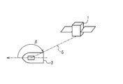
- FIG. 1 is a schematic diagram when capturing a radar image.
- FIG. 2 is a diagram for explaining an incident angle when capturing a radar image.
- FIG. 3 is a diagram for explaining an irradiation direction when capturing a radar image.
- FIG. 4 is a diagram showing the configuration of the image identification system.
- FIG. 5 is a diagram showing a configuration of the image identification device.
- FIG. 6 is a diagram showing the configuration of the image identification program.
- FIG. 7 is a diagram showing a configuration of the data generation device.
- FIG. 8 is a diagram showing the configuration of the data generation program.
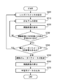
- FIG. 9 is a flowchart relating to the processing of the data generation program.
- a radar image is obtained by synthesizing images obtained by photographing an object from a plurality of directions. For this reason, as shown in FIG. 1, the artificial satellite 1 irradiates the radar to the ship 3, which is the target, while moving, and captures a radar image by receiving the reflected wave. Thereby, the artificial satellite 1 can acquire radar images captured from a plurality of points, and obtains a radar image by synthesizing the plurality of radar images. For this reason, it is difficult for the radar image to show a detailed shape of the moving object, the ship 3 swaying in the waves, and the like.
- a radar image generally indicates the magnitude of the amplitude of a reflected wave as luminance. Specifically, a portion with high luminance indicates a position where the amplitude is large, in other words, a position where the energy of the reflected wave is large.
- the radar image greatly changes depending on the angle of the radar with which the artificial satellite 1 irradiates the ship 3.
- the angle of the radar that the artificial satellite 1 irradiates the ship 3 can be mainly defined by the incident angle ⁇ and the irradiation direction ⁇ .
- the angle of incidence ⁇ is defined by a line 5 connecting the artificial satellite 1 and the ship 3, that is, a line connecting the synthetic aperture radar or the inverse synthetic aperture radar and the ship 3 and a vertical direction at the position of the ship 3. Indicates the angle formed.
- FIG. 2 the angle of incidence ⁇ is defined by a line 5 connecting the artificial satellite 1 and the ship 3, that is, a line connecting the synthetic aperture radar or the inverse synthetic aperture radar and the ship 3 and a vertical direction at the position of the ship 3. Indicates the angle formed.
- the irradiation direction ⁇ indicates an angle between a straight line 5 connecting the artificial satellite 1 and the ship 3 and the traveling direction of the ship 3 when viewed from the vertical direction of the ship 3.
- the irradiation direction ⁇ indicates a clockwise angle from the traveling direction of the ship 3 to the direction of the artificial satellite 1 relative to the ship 3. Therefore, the irradiation direction ⁇ has a range from 0 degrees to 360 degrees.
- the irradiation direction ⁇ indicates 0 to 180 degrees.
- the irradiation direction ⁇ indicates 180 degrees to 360 degrees.
- the radar image differs depending on the incident angle ⁇ and the irradiation azimuth ⁇ even when the same ship 3 is photographed.
- the artificial satellite 1 transmits the acquired radar image to the land facility 2 as shown in FIG.
- the land facility 2 identifies the received radar image.
- the artificial satellite 1 includes an image acquisition device 10 that acquires a radar image.
- the land facility 2 includes an image identification system 20 for identifying a radar image.
- the image acquisition device 10 includes a radar for acquiring a radar image, for example, an SAR.
- the image acquisition device 10 transmits a radar image obtained by the radar to the image identification system 20.
- the image identification system 20 includes an image identification device 30 and a data generation device 40.
- the image identification device 30 identifies the type of object photographed in the radar image.
- the data generation device 40 generates learning data used for learning of the image identification device 30.
- the types of objects include the types and types of vehicles such as vehicles, passenger ships, fishing boats, ships, cargo ships, and tankers.
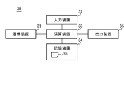
- the image identification device 30 includes a communication device 31, an input device 32, an arithmetic device 33, a storage device 34, and an output device 35.
- the communication device 31 communicates with the outside and receives a radar image or the like transmitted by the artificial satellite 1.
- the communication device 31 is connected to the arithmetic device 33 and outputs the received data to the arithmetic device 33. Further, the communication device 31 transmits data input from the arithmetic device 33 to an external device.
- the communication device 31 for example, a LAN (Local Area Network), a NIC (Network Interface Card) connected to a WAN (Wide Area Network) or the like, a USB (Universal Serial Bus) directly connected to an external device, and wireless communication for performing wireless communication
- LAN Local Area Network
- NIC Network Interface Card
- WAN Wide Area Network
- USB Universal Serial Bus
- the input device 32 receives an input of data required for calculation.
- the input device 32 outputs the input data to the arithmetic device 33.
- the input device 32 includes various devices such as a keyboard, a mouse, a microphone, and a touch panel.
- the arithmetic unit 33 reads the image identification program 36 stored in the storage device 34 and executes the image identification program 36. In addition, data input from the communication device 31 and the input device 32 is stored in the storage device 34 as necessary.
- the arithmetic unit 33 includes a central processing unit (CPU: Central Processing Unit).
- the storage device 34 stores the image identification program 36 and data necessary for the arithmetic device 33 to execute the image identification program 36.
- the storage device 34 outputs the stored data to the arithmetic device 33 based on the instruction from the arithmetic device 33.
- the storage device 34 includes various devices such as a readable and writable recording medium and a read-only recording medium.
- the readable and writable recording medium includes an HDD (Hard Disk Drive), a USB memory, and the like.
- the read-only recording medium includes a CD (Compact @ Disk) and the like.
- the output device 35 outputs the result of the processing executed by the arithmetic device 33 and the like.
- the output device 35 includes a display device such as a liquid crystal display, and displays a result processed by the arithmetic device 33.
- the output device 35 includes various devices that notify the user, such as a speaker and a warning light.
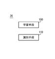
- the image identification device 30 identifies an image by the processing performed by the arithmetic device 33 based on the image identification program 36 stored in the storage device 34. Therefore, as shown in FIG. 6, the image identification program 36 includes a learning unit 100 and an identification unit 110.
- the learning means 100 has a learning function to identify a radar image using deep learning. For example, the structure of the deep neural network and parameters are set as initial values in the image identification program 36. By inputting a large number of learning data including learning images into the deep neural network, the structure and parameters of the deep neural network are updated.
- the learning means 100 includes means for setting initial values of the structure and parameters of the deep neural network, and means for updating.
- the identification means 110 has a function of identifying a radar image using deep learning. For example, the identification unit 110 identifies a radar image using the deep neural network learned by the learning unit 100.
- the learning means 100 updates the structure of the deep neural network and the parameters so that the radar image can be identified. Therefore, when a radar image is input to the learned deep neural network, an object photographed in the radar image can be identified, and data indicating the type of the identified object can be output.
- the image identification device 30 learns using the learning data, and identifies the type of object photographed in the radar image.
- the data generation device 40 includes a communication device 41, an input device 42, an arithmetic device 43, a storage device 44, and an output device 45.
- the communication device 41, the input device 42, and the output device 45 function similarly to the communication device 31, the input device 32, and the output device 35 of the image identification device 30, respectively.
- the arithmetic unit 43 reads out the data generation program 46 stored in the storage device 44 and executes the data generation program 46. Further, similarly to the arithmetic device 33 of the image identification device 30, the data input from the communication device 41 and the input device 42 is stored in the storage device 44 as necessary.
- the arithmetic unit 43 includes a central processing unit.
- the storage device 44 stores a data generation program 46 and data necessary for the arithmetic device 43 to execute the data generation program 46.
- the storage device 44 outputs the stored data to the arithmetic device 43 based on an instruction from the arithmetic device 43.
- the storage device 44 includes various devices such as a readable and writable recording medium and a read-only recording medium, like the storage device 34 of the image identification device 30.
- the data generation program 46 generates learning data for the image identification device 30 to learn using a radar image of a known target.
- the data generation program 46 includes an environment setting unit 200, a model setting unit 210, an image calculation unit 220, and a data output unit 230.
- the model setting unit 210 sets model data indicating a 3D model of the captured object in the radar image.
- the image calculating unit 220 calculates a simulation image of the 3D model set by the model setting unit 210 using a simulation for calculating a radar image obtained by SAR or ISAR.
- the environment setting unit 200 sets parameters for the image calculation unit 220 to perform a simulation. These parameters include radar parameters indicating the incident angle ⁇ of the radar, the irradiation direction ⁇ , and the like.
- the data output unit 230 outputs learning data in which the type of the target object is associated with the calculated simulation image.
- the environment setting unit 200 holds radar parameters of a radar image obtained by photographing a known target.
- the environment setting unit 200 sets radar parameters of a radar image obtained by photographing a known target.
- the radar parameters may include data indicating radar characteristics such as a radar band, a polarization direction, and image resolution, in addition to the incident angle ⁇ and the irradiation direction ⁇ .
- the environment setting unit 200 may hold a first radar parameter set and a second radar parameter set.
- the first radar parameter set includes the radar parameters already used for calculating the simulation image in the processing after step S210.
- the second radar parameter set includes one or more radar parameters corresponding to a radar image.
- the environment setting means 200 adds the set radar parameters to the first radar parameter set.
- the radar parameters used for calculating the simulation image are included in the first radar parameter set.
- the model setting means 210 sets model data of a 3D model to be input to the simulator.
- the shape of this 3D model indicates the shape of a known target imaged in the radar image.
- the reflectance is set according to the assumed material. For example, the reflectance is set high in a metal portion, and the reflectance is set low in a portion such as wood.
- the model setting unit 210 provides an application for creating a 3D model, and sets the 3D model based on data input to the input device 42 by a user. Further, the model setting means 210 may select a 3D model prepared in advance. Further, the model setting unit 210 may generate a 3D model based on a photograph (for example, an optical image) of the object, a drawing, or the like.
- step S220 the image calculation means 220 calculates a simulation image obtained by irradiating the set 3D model with a radar, for example, an SAR.
- the image calculation unit 220 executes a simulation based on the 3D model and the radar parameters.
- a simulation image is calculated as a result of the simulation.
- the data output unit 230 holds a radar image of a known target.
- the data output unit 230 outputs the simulation image calculated by the image calculation unit 220 and the radar image of the target object to the output device 45.
- the simulation image and the radar image are displayed side by side for easy comparison.
- the user compares the simulation image with the radar image. If the simulation image is different from the radar image, the user inputs model correction data for correcting the size, aspect ratio, detailed shape, reflectance of each part, etc. of the 3D model, and the process proceeds to step S210. I do.
- the model setting unit 210 corrects the 3D model based on the model correction data. For example, at the same position, the luminance of the radar image is compared with the luminance of the simulation image.
- model correction data is input so that the model setting unit 210 increases the reflectance of the 3D model corresponding to the position.
- model correction data is input so that the model setting unit 210 lowers the reflectance of the 3D model corresponding to the position.
- the model correction data is input assuming that there is no difference between the simulation image and the radar image.
- the metal wire includes a communication antenna of the ship 3 and a metal fence for preventing falling.
- the metal member includes a metal reinforcing material and a connecting material of a wooden ship. If there is no difference between the simulation image and the radar image, or if the difference is acceptable, the process proceeds to step S240.
- step S240 the environment setting unit 200 determines whether there is a radar image based on another radar parameter. If there is a radar image with another radar parameter, the process returns to step S200 and changes the radar parameter. Steps S210 to S230 are executed based on the changed radar parameters and the corresponding radar images, and the 3D model is modified. If there is no radar image with another radar parameter, the environment setting unit 200 determines that the 3D model has been determined, and proceeds to step S250. Specifically, the environment setting unit 200 checks whether all the radar parameters included in the second radar parameter set are included in the first radar parameter set. The first radar parameter set includes the radar parameters set once in the calculation of the simulation image. On the other hand, the second radar parameter set includes radar parameters corresponding to existing radar images.
- the process returns to step S200, and sets a radar parameter not included in the first radar parameter set.
- the 3D model is corrected using the radar parameters that have not been used for calculating the simulation image.
- the process proceeds to step S250. Thereby, a 3D model can be set for all radar parameters corresponding to an existing radar image. If it is not necessary to correct the 3D model for a plurality of radar parameters, this processing may be omitted.
- step S240 the difference between the actually captured radar image and the simulation image is reduced.
- a radar image from one direction includes a part that is shadowed and is not photographed. Further, when the band of the radar is different, the reflectance changes depending on the material. Therefore, by setting a 3D model using a radar image based on a plurality of radar parameters, a more detailed structure of the target object can be set in the 3D model. Therefore, a simulation image is generated using a 3D model in which a more detailed structure is set. As a result, the image identification device 30 that has learned using the simulation image has a high identification rate.
- step S250 the environment setting unit 200 sets a plurality of radar parameters of the radar that irradiates the 3D model.
- a plurality of radar parameters are set by combining a value of each band used when setting the 3D model, a value of an arbitrary incident angle ⁇ , and a value of an arbitrary irradiation direction ⁇ .
- step S260 the image calculation unit 220 calculates a plurality of simulated images corresponding to each of the plurality of radar parameters set by the environment setting unit 200. That is, the image calculation unit 220 calculates one simulation image for one radar parameter.
- step S270 the data output unit 230 outputs learning data including the simulation image calculated by the image calculation unit 220 and data indicating the type of the object.
- the simulation image is associated with data indicating the type of the target object.
- the image identification device 30 performs deep learning using the learning data output from the data output unit 230.
- the difference between the learning data output by the data output means 230 and the radar image of the target is small. For this reason, the image identification device 30 can obtain a high identification rate by performing deep learning using the learning data.
- the learning data may include radar parameters such as the value of the incident angle ⁇ and the value of the radar band.
- the simulation image, the radar parameters used for the calculation of the simulation image, and the data indicating the type of the target object are associated with each other. Since the radar parameters such as the value of the radar band are the specifications of the radar image, they are determined by the photographed radar image. Therefore, when a radar image is identified by the identification unit 110, a radar parameter can be input to the image identification device 30. That is, the image identification device 30 can identify the radar image using the radar parameters by inputting the radar parameters at the time of learning. For this reason, the image identification device 30 can improve the identification rate.
- the image calculation means 220 may calculate a simulation image according to a change in the state of the ship 3 such as shaking and speed. For example, when the speed of the ship 3 is high, the ship 3 is captured in a radar image in a shape extending in the traveling direction. For this reason, the image calculation means 220 may calculate a simulation image by calculating and synthesizing a radar image in which the position of the ship 3 is changed according to the speed of the artificial satellite 1 and the speed of the ship 3. .
- the image calculation means 220 may calculate a simulation image including not only the ship 3 but also data indicating a peripheral 3D model of the bay facility. Further, when the wave is high, the radar image becomes unclear due to the motion of the ship 3. Therefore, the image calculating unit 220 may set the motion of the ship 3 and calculate the simulation image. Further, the image calculation unit 220 may set the position of the waterline of the ship 3 and calculate the simulation image.
- the image calculation unit 220 may correct the simulation image based on the motion and the speed of the ship 3. For example, when the ship 3 is shaking due to a high wave, or when the ship 3 is berthing, the image calculation unit 220 may add noise to the contour of the ship 3 in the simulation image. When the speed of the ship 3 is high, the image calculation unit 220 may correct the simulation image so that the ship 3 extends in the traveling direction.
- the model setting means 210 may set the speed of the target in step S210 when the target captured in the radar image is moving.
- the image calculation unit 220 performs a simulation reflecting the set speed, and calculates a simulated image. This makes it possible to easily compare the simulation image with the radar image even when the target imaged in the radar image is moving.
- the model setting unit 210 can set the 3D model in more detail. As a result, the identification rate of the image identification device 30 can be improved.
- the model setting means 210 may set data indicating a 3D model around the bay facility.
- the image calculation unit 220 arranges the set 3D model of the bay facility and the 3D model of the target object, and calculates a simulation image. By comparing the calculated simulation image with the radar image and correcting the 3D model, the 3D model can be set in more detail.
- the model setting means 210 may set the wave height, the position of the waterline, and the like in step S210.
- the image calculation unit 220 arranges the 3D model of the object so as to be at the set waterline, and shakes the object according to the wave height to calculate a simulation image. Further, the image calculation means 220 may calculate a simulation image by adding a change in the sea level due to a wave height, a wave cycle, or the like.
- the model setting unit 210 sets the target object and the surrounding conditions, the comparison between the calculated simulation image and the radar image can be facilitated. Therefore, the 3D model of the object can be set in detail. Since a simulated image included in the learning data can be calculated using the 3D model set in detail, the image identification device 30 that has learned using the learning data has high identification power.
- the data generation device 40 may calculate a simulation image in which the speed of a target object, surrounding facilities such as a bay shore facility, a wave height, a waterline, and the like are changed, and include the simulation image in the learning data. Accordingly, learning data corresponding to various situations of the target object can be obtained, and therefore, the image identification device 30 that has learned using the learning data has high identification power. Further, the data generation device 40 may calculate a simulation image in which the distance between the artificial satellite 1 and the target is changed, and include the simulation image in the learning data. Further, the learning data may include environmental parameters including data that can be acquired as a situation when a radar image is captured, such as a wave height, a wave cycle, and a distance between the artificial satellite 1 and the target. In this case, the environmental parameters, the simulation image, and the data indicating the type of the target are associated with each other.
- the ship 3 has been described as an example of an object, any object can be selected as long as it can be photographed with a radar image.
- the target object is a vehicle, an aircraft, a land facility, or the like.
- the data output unit 230 outputs a radar image and a simulation image as difference data, but the present invention is not limited to this. It is sufficient that the user can confirm the difference between the radar image and the simulation image, and an arbitrary method can be selected. For example, the data output unit 230 may compare the radar image with the simulation image and output an image in which different regions are highlighted. Further, the data output unit 230 may output an image indicating the difference in luminance between the radar image and the simulation image as luminance.
- the data output means 230 may output model correction data based on the difference data. Specifically, the data output unit 230 calculates a difference in luminance between the position of the radar image and the position of the corresponding simulation image. Next, the data output unit 230 searches for a position where the calculated difference in luminance is larger than a predetermined threshold. The data output unit 230 outputs model correction data for correcting the reflectance of the 3D model corresponding to the searched position. As described above, the data output unit 230 searches for a position different between the luminance of the radar image and the luminance of the simulation image as the correction position, and outputs the model correction data for changing the setting of the 3D model corresponding to the correction position. Good.
- the processing described above is an example, and the order of the steps and the processing contents may be changed without impairing the function. Further, the configuration described above may be arbitrarily changed within a range not to impair the function.
- the artificial satellite 1 may transmit data of an image captured at each point to the land facility 2, and calculate a radar image in which the images are combined in the land facility 2.
- one device may have the function of the image identification device 30 and the function of the data generation device 40.
- the functions of the image identification device 30 and the functions of the data generation device 40 may be executed by a plurality of devices.
- the data generation device 40 may not include the input device 42 and the output device 45.
- the communication device 41 communicates with an external device including the input device 42 and the output device 45 to receive input data and transmit output data.
- the image identification device 30 may not include the input device 32 and the output device 35. Further, the image identification device 30 may select various identification methods without being limited to the deep learning. Further, the image identification device 30 may identify some or all of the environmental parameters such as data indicating the speed of the target object together with the type of the object. By identifying an environmental parameter such as data indicating the speed, the image identification device 30 can exclude a result in which the speed or the like is obviously wrong for the type of the target object.
Landscapes
- Engineering & Computer Science (AREA)
- Remote Sensing (AREA)
- Radar, Positioning & Navigation (AREA)
- Physics & Mathematics (AREA)
- General Physics & Mathematics (AREA)
- Theoretical Computer Science (AREA)
- Computer Networks & Wireless Communication (AREA)
- Artificial Intelligence (AREA)
- Evolutionary Computation (AREA)
- Electromagnetism (AREA)
- Life Sciences & Earth Sciences (AREA)
- Mathematical Physics (AREA)
- Computational Linguistics (AREA)
- General Health & Medical Sciences (AREA)
- Molecular Biology (AREA)
- Computing Systems (AREA)
- General Engineering & Computer Science (AREA)
- Data Mining & Analysis (AREA)
- Software Systems (AREA)
- Biophysics (AREA)
- Biomedical Technology (AREA)
- Health & Medical Sciences (AREA)
- Computer Vision & Pattern Recognition (AREA)
- Radar Systems Or Details Thereof (AREA)
- Image Analysis (AREA)
Abstract
データ生成装置は、環境設定手段(200)と、モデル設定手段(210)と、画像算出手段(220)と、データ出力手段(230)とを備える。環境設定手段は、合成開口レーダまたは逆合成開口レーダであるレーダの仕様を示すレーダパラメータを設定する。モデル設定手段は、識別する対象物の形状を示す3Dモデルを設定する。画像算出手段は、3Dモデルと、レーダパラメータとに基づき、模擬画像を算出する。データ出力手段は、模擬画像と、対象物の種類とを関連付けた学習用データを出力する。また、データ出力手段は、レーダ画像と模擬画像との差異を示す差異データを出力する。モデル設定手段は、差異データに基づき入力されたモデル修正データに基づき、3Dモデルを変更する。このデータ生成装置により、レーダ画像を対象とした画像識別装置の識別率が向上される。
Description
本発明は、データ生成装置、画像識別装置、データ生成方法及び記憶媒体に関するものである。
画像に撮影されている対象物を識別する画像識別装置が知られている。例えば、画像識別装置は、対象物が既知のサンプル画像と識別対象の画像とを照合し、最も合致しているサンプル画像を検索する。画像識別装置は、識別対象の画像に撮影されている物を、検索したサンプル画像に対応する対象物であると識別する。
特許文献1(特開2003-331289号公報)には、多数のサンプル画像を必要とする合成開口レーダ(SAR:Synthetic Aperture Radar)または逆合成開口レーダ(ISAR:Inverse Synthetic Aperture Radar)により得られるSAR画像またはISAR画像に対して、パターンマッチングにより画像を識別する方法が開示されている。この方法は、パターンマッチングの結果に対して、データマイニングとニューラルネットワークとを用いて識別することで、識別率の向上とメモリの削減を図っている。
さらに、特許文献1には、この多数のサンプル画像をシミュレーションにより得ることが記載されている。具体的には、識別すべき対象物の3Dモデルを予め用意する。この3Dモデルの撮影方向を変更して得られる画像をサンプル画像として利用する。
SAR画像またはISAR画像は、船舶の検出には利用されるが、船舶の識別に利用することは難しい。このため、SAR画像またはISAR画像に撮影された船舶などを識別することが求められている。
本発明は、以上の状況に鑑みなされたものであり、SAR画像またはISAR画像を対象とした画像識別装置の識別率を向上させるための学習用データを提供することを目的の1つとする。他の目的については、以下の記載及び実施の形態の説明から理解することができる。
上記目的を達成するための一実施の形態によるデータ生成装置は、環境設定手段と、モデル設定手段と、画像算出手段と、データ出力手段とを備える。環境設定手段は、合成開口レーダまたは逆合成開口レーダであるレーダの仕様を示すレーダパラメータを設定する。モデル設定手段は、識別する対象物の形状を示す3Dモデルを設定する。画像算出手段は、3Dモデルと、レーダパラメータとに基づき、模擬画像を算出する。データ出力手段は、レーダにより得られる対象物のレーダ画像を保持し、レーダ画像と、模擬画像との差異を示す差異データを出力する。また、モデル設定手段は、差異データに基づき入力されたモデル修正データに基づき、3Dモデルを変更する。環境設定手段は、3Dモデルが決定されたと判断すると、複数のレーダパラメータを設定する。画像算出手段は、複数のレーダパラメータのそれぞれに対応した複数の模擬画像を算出する。データ出力手段は、複数の模擬画像と、対象物の種類とを関連付けた学習用データを出力する。このときの学習用データは、入力された画像に撮影された物の種類を識別する画像識別装置が学習するためのデータである。
一実施の形態による画像識別装置は、学習手段と、識別手段とを備える。学習手段は、前述のデータ生成装置で生成した学習データを用いて学習する。識別手段は、学習手段の結果に基づき、入力された画像に撮影された物の種類を識別する。
一実施の形態によるデータ生成方法は、演算装置が実行する以下のステップを含む。
・合成開口レーダまたは逆合成開口レーダであるレーダの仕様を示すレーダパラメータを設定するステップ
・識別する対象物の形状を示す3Dモデルを設定するステップ
・3Dモデルとレーダパラメータとに基づき、模擬画像を算出するステップ
・レーダにより得られる対象物のレーダ画像と、模擬画像との差異を示す差異データを出力するステップ
・差異データに基づき入力されたモデル修正データに基づき、3Dモデルを変更するステップ
・3Dモデルが決定されたと判断されると、複数のレーダパラメータを設定するステップ
・複数のレーダパラメータのそれぞれに対応した複数の模擬画像を算出するステップ
・複数の模擬画像と、対象物の種類とを関連付けた学習用データを出力するステップ
このときの学習用データは、入力された画像に撮影された物の種類を識別する画像識別装置が学習するためのデータである。
・合成開口レーダまたは逆合成開口レーダであるレーダの仕様を示すレーダパラメータを設定するステップ
・識別する対象物の形状を示す3Dモデルを設定するステップ
・3Dモデルとレーダパラメータとに基づき、模擬画像を算出するステップ
・レーダにより得られる対象物のレーダ画像と、模擬画像との差異を示す差異データを出力するステップ
・差異データに基づき入力されたモデル修正データに基づき、3Dモデルを変更するステップ
・3Dモデルが決定されたと判断されると、複数のレーダパラメータを設定するステップ
・複数のレーダパラメータのそれぞれに対応した複数の模擬画像を算出するステップ
・複数の模擬画像と、対象物の種類とを関連付けた学習用データを出力するステップ
このときの学習用データは、入力された画像に撮影された物の種類を識別する画像識別装置が学習するためのデータである。
一実施の形態による記憶媒体には、演算装置に以下のステップを実行させるプログラムが記載されている。
・合成開口レーダまたは逆合成開口レーダであるレーダの仕様を示すレーダパラメータを設定するステップ
・識別する対象物の形状を示す3Dモデルを設定するステップ
・3Dモデルとレーダパラメータとに基づき、模擬画像を算出するステップ
・レーダにより得られる対象物のレーダ画像と、模擬画像との差異を示す差異データを出力するステップ
・差異データに基づき入力されたモデル修正データに基づき、3Dモデルを変更するステップ
・3Dモデルが決定されたと判断されると、複数のレーダパラメータを設定するステップ
・複数のレーダパラメータのそれぞれに対応した複数の模擬画像を算出するステップ
・複数の模擬画像と、対象物の種類とを関連付けた学習用データを出力するステップ
このときの学習用データは、入力された画像に撮影された物の種類を識別する画像識別装置が学習するためのデータである。
・合成開口レーダまたは逆合成開口レーダであるレーダの仕様を示すレーダパラメータを設定するステップ
・識別する対象物の形状を示す3Dモデルを設定するステップ
・3Dモデルとレーダパラメータとに基づき、模擬画像を算出するステップ
・レーダにより得られる対象物のレーダ画像と、模擬画像との差異を示す差異データを出力するステップ
・差異データに基づき入力されたモデル修正データに基づき、3Dモデルを変更するステップ
・3Dモデルが決定されたと判断されると、複数のレーダパラメータを設定するステップ
・複数のレーダパラメータのそれぞれに対応した複数の模擬画像を算出するステップ
・複数の模擬画像と、対象物の種類とを関連付けた学習用データを出力するステップ
このときの学習用データは、入力された画像に撮影された物の種類を識別する画像識別装置が学習するためのデータである。
本発明によれば、高い識別率を有する画像識別装置を得るための学習用データを生成することができる。
合成開口レーダまたは逆合成開口レーダであるレーダにより得られるレーダ画像では、対象物の詳細な形状を把握するのが難しい。このことから、発明者らは、レーダ画像を識別するために、深層学習(Deep Learning)を用いることが有用であることを見出した。深層学習を用いるためには、多数の学習用画像が必要である。しかし、レーダ画像は高額であるため、実際に撮影されたレーダ画像を多数用意するのは難しい。
3Dモデルとシミュレータとを用いることで、多数のレーダ画像の模擬画像(simulation image)を得ることができる。しかし、シミュレータを用いて得られる模擬画像と、実際に撮影されたレーダ画像との間で差異が生じる。発明者らは、船舶の形状が詳細に表現されていないレーダ画像において、この差異が識別率に大きく影響することを見出し、本発明に至った。
(実施の形態)
レーダ画像は、対象物を複数の方向から撮影した画像を合成することにより取得される。このため、図1に示すように、人工衛星1は、移動しながら、対象物である船舶3にレーダを照射し、その反射波を受信することでレーダ画像を撮影する。これにより、人工衛星1は、複数の地点から撮影したレーダ画像を取得でき、この複数のレーダ画像を合成することで、レーダ画像を得る。このため、レーダ画像には、移動している対象物、波に揺れている船舶3などの詳細な形状が写りにくい。レーダ画像は、一般に反射波の振幅の大きさを輝度として示している。具体的には、輝度の高い部分は、振幅が大きい位置、言い換えると反射波のエネルギーが大きい位置を示す。
レーダ画像は、対象物を複数の方向から撮影した画像を合成することにより取得される。このため、図1に示すように、人工衛星1は、移動しながら、対象物である船舶3にレーダを照射し、その反射波を受信することでレーダ画像を撮影する。これにより、人工衛星1は、複数の地点から撮影したレーダ画像を取得でき、この複数のレーダ画像を合成することで、レーダ画像を得る。このため、レーダ画像には、移動している対象物、波に揺れている船舶3などの詳細な形状が写りにくい。レーダ画像は、一般に反射波の振幅の大きさを輝度として示している。具体的には、輝度の高い部分は、振幅が大きい位置、言い換えると反射波のエネルギーが大きい位置を示す。
また、レーダ画像は、人工衛星1が船舶3に照射するレーダの角度により、大きく変化する。人工衛星1が船舶3に照射するレーダの角度は、主に入射角αと照射方位βとで規定できる。入射角αは、図2に示すように、人工衛星1と船舶3とを結ぶ直線5、つまり合成開口レーダまたは逆合成開口レーダと船舶3とを結ぶ直線と船舶3の位置における鉛直方向との成す角を示す。照射方位βは、図3に示すように、船舶3の鉛直方向から見たときの、人工衛星1と船舶3とを結ぶ直線5と船舶3の進行方向との成す角を示す。詳細には、照射方位βは、船舶3の進行方向から、船舶3に相対的な人工衛星1の方向までの時計回りの角度を示す。このため、照射方位βは、0度から360度までの範囲を有する。具体的には、船舶3の進行方向を向いたとき、船舶3に対して人工衛星1が右方向にある場合、照射方位βは0度から180度を示す。船舶3に対して人工衛星1が左方向にある場合、照射方位βは180度から360度を示す。レーダ画像は、同じ船舶3を撮影しても、入射角α、照射方位βに応じて異なる。
このレーダ画像を識別するために、人工衛星1は、図1に示すように、取得したレーダ画像を陸上施設2に送信する。陸上施設2は、受信したレーダ画像を識別する。具体的には、図4に示すように、人工衛星1は、レーダ画像を取得する画像取得装置10を備える。陸上施設2は、レーダ画像を識別する画像識別システム20を備える。
画像取得装置10は、レーダ画像を取得するためのレーダ、例えばSARを備える。画像取得装置10は、レーダにより得られるレーダ画像を画像識別システム20に送信する。
画像識別システム20には、画像識別装置30と、データ生成装置40とを備える。画像識別装置30は、レーダ画像に撮影された物の種類を識別する。データ生成装置40は、画像識別装置30の学習に使用する学習用データを生成する。物の種類には、車両、客船、漁船、艦艇、貨物船、タンカーなどの移動体の種類、機種などを含む。
(画像識別装置)
画像識別装置30は、図5に示すように、通信装置31と、入力装置32と、演算装置33と、記憶装置34と、出力装置35とを備える。通信装置31は、外部との通信を行い、人工衛星1が送信するレーダ画像などを受信する。通信装置31は、演算装置33に接続され、受信したデータを演算装置33に出力する。また、通信装置31は、演算装置33から入力されるデータを外部の装置に送信する。通信装置31として、例えば、LAN(Local Area Network)、WAN(Wide Area Network)などに接続するNIC(Network Interface Card)、外部装置と直接接続するUSB(Universal Sirial Bus)、無線通信を行うためのアンテナなどの種々の装置が例示される。
画像識別装置30は、図5に示すように、通信装置31と、入力装置32と、演算装置33と、記憶装置34と、出力装置35とを備える。通信装置31は、外部との通信を行い、人工衛星1が送信するレーダ画像などを受信する。通信装置31は、演算装置33に接続され、受信したデータを演算装置33に出力する。また、通信装置31は、演算装置33から入力されるデータを外部の装置に送信する。通信装置31として、例えば、LAN(Local Area Network)、WAN(Wide Area Network)などに接続するNIC(Network Interface Card)、外部装置と直接接続するUSB(Universal Sirial Bus)、無線通信を行うためのアンテナなどの種々の装置が例示される。
入力装置32は、演算に必要となるデータの入力を受け付ける。入力装置32は、入力されたデータを演算装置33に出力する。入力装置32は、キーボード、マウス、マイク、タッチパネルなどの種々の装置が含まれる。
演算装置33は、記憶装置34に格納された画像識別プログラム36を読み出し、画像識別プログラム36を実行する。また、通信装置31と入力装置32とから入力されたデータを必要に応じて、記憶装置34に格納する。演算装置33には、中央処理装置(CPU:Central Processing Unit)などが含まれる。
記憶装置34は、画像識別プログラム36と、演算装置33が画像識別プログラム36を実行するために必要なデータとを格納する。記憶装置34は、演算装置33からの指示に基づき、格納しているデータを演算装置33に出力する。記憶装置34は、読み書き可能な記録媒体、読み出し専用記録媒体などの種々の装置を含む。読み書き可能な記録媒体には、HDD(Hard Disk Drive)、USBメモリなどが含まれる。読み出し専用記録媒体には、CD(Compact Disk)などが含まれる。
出力装置35は、演算装置33が実行した処理の結果などを出力する。例えば、出力装置35には、液晶ディスプレイなどの表示装置が含まれ、演算装置33が処理した結果を表示する。また、出力装置35には、スピーカ、警告灯など、ユーザに報知する種々の装置が含まれる。
このように、画像識別装置30は、記憶装置34に格納された画像識別プログラム36に基づき演算装置33が処理を行うことで、画像を識別する。このため、画像識別プログラム36には、図6に示すように、学習手段100と、識別手段110とが含まれる。
学習手段100は、深層学習を用いてレーダ画像を識別するために、学習する機能を有する。例えば、画像識別プログラム36には、初期値としてディープニューラルネットワークの構造と、パラメータとが設定されている。このディープニューラルネットワークに、学習用画像を含む多数の学習用データを入力することで、ディープニューラルネットワークの構造とパラメータとを更新する。学習手段100には、このディープニューラルネットワークの構造とパラメータとの初期値を設定する手段と、更新する手段とが含まれる。
識別手段110は、深層学習を用いて、レーダ画像を識別する機能を有する。例えば、識別手段110は、学習手段100により学習されたディープニューラルネットワークを用いて、レーダ画像を識別する。学習手段100により、ディープニューラルネットワークの構造と、パラメータとは、レーダ画像を識別できるように更新されている。このため、学習したディープニューラルネットワークに、レーダ画像を入力すると、レーダ画像に撮影されている物を識別し、識別した物の種類を示すデータを出力することができる。
このように、画像識別装置30は、学習用データを用いて学習し、レーダ画像に撮影されている物の種類を識別する。
(データ生成装置)
データ生成装置40は、図7に示すように、通信装置41と、入力装置42と、演算装置43と、記憶装置44と、出力装置45とを備える。通信装置41と、入力装置42と、出力装置45とは、それぞれ、画像識別装置30の通信装置31と、入力装置32と、出力装置35と同様に機能する。
データ生成装置40は、図7に示すように、通信装置41と、入力装置42と、演算装置43と、記憶装置44と、出力装置45とを備える。通信装置41と、入力装置42と、出力装置45とは、それぞれ、画像識別装置30の通信装置31と、入力装置32と、出力装置35と同様に機能する。
演算装置43は、記憶装置44に格納されたデータ生成プログラム46を読み出し、データ生成プログラム46を実行する。また、画像識別装置30の演算装置33と同様に、通信装置41と、入力装置42とから入力されたデータを必要に応じて、記憶装置44に格納する。演算装置43には中央処理装置が含まれる。
記憶装置44は、データ生成プログラム46と、演算装置43がデータ生成プログラム46を実行するために必要となるデータとを格納する。記憶装置44は、演算装置43からの指示に基づき、格納しているデータを演算装置43に出力する。記憶装置44は、画像識別装置30の記憶装置34と同様に、読み書き可能な記録媒体、読み出し専用記録媒体などの種々の装置を含む。
データ生成プログラム46は、既知の対象物が撮影されたレーダ画像を用いて、画像識別装置30が学習するための学習用データを生成する。データ生成プログラム46は、図8に示すように、環境設定手段200と、モデル設定手段210と、画像算出手段220と、データ出力手段230とを備える。モデル設定手段210は、レーダ画像に撮影された対象物の3Dモデルを示すモデルデータを設定する。画像算出手段220は、SARまたはISARにより得られるレーダ画像を算出するシミュレーションを用いて、モデル設定手段210が設定した3Dモデルの模擬画像を算出する。環境設定手段200は、画像算出手段220がシミュレーションを行うためのパラメータを設定する。このパラメータには、レーダの入射角α、照射方位βなどを示すレーダパラメータが含まれる。データ出力手段230は、対象物の種類と、算出した模擬画像とを関連付けた学習用データを出力する。
データ生成装置40を用いて、模擬画像を含む学習用データを生成する方法を示す。データ生成装置40は、データ生成プログラム46を実行すると、図9に示すデータ生成方法を実行する。環境設定手段200は、既知の対象物が撮影されたレーダ画像のレーダパラメータを保持する。ステップS200において、環境設定手段200は、既知の対象物が撮影されたレーダ画像のレーダパラメータを設定する。レーダパラメータには、入射角α、照射方位βのほか、レーダのバンド、偏波方向、画像分解能などのレーダ特性を示すデータが含まれてもよい。また、複数のレーダ画像がある場合、環境設定手段200は、第1レーダパラメータセットと、第2レーダパラメータセットとを保持してもよい。この場合、第1レーダパラメータセットは、ステップS210以降の処理において模擬画像を算出するために既に用いたレーダパラメータを含む。第2レーダパラメータセットは、レーダ画像に対応したレーダパラメータを1以上含む。環境設定手段200は、設定したレーダパラメータを、第1レーダパラメータセットに加える。これにより、模擬画像を算出するために用いたレーダパラメータは、第1レーダパラメータセットに含まれる。
ステップS210において、モデル設定手段210は、シミュレータに入力するための3Dモデルのモデルデータを設定する。この3Dモデルの形状は、レーダ画像に撮影された既知の対象物の形状を示す。また、3Dモデルの各部について、想定される材料に応じた反射率を設定する。例えば、金属の部分では反射率を高く設定し、木材などの部分では反射率を低く設定する。モデル設定手段210は、3Dモデルを作成するためのアプリケーションを提供し、ユーザが入力装置42に入力するデータに基づき3Dモデルを設定する。また、モデル設定手段210は、予め用意されている3Dモデルを選択してもよい。また、対象物の写真(例えば、光学画像)、図面などに基づき、モデル設定手段210が3Dモデルを生成してもよい。
ステップS220において、画像算出手段220は、設定された3Dモデルにレーダ、例えばSARを照射することで得られる模擬画像を算出する。画像算出手段220は、3Dモデルと、レーダパラメータとに基づき、シミュレーションを実行する。シミュレーションの実行結果として、模擬画像が算出される。
データ出力手段230は、既知の対象物が撮影されたレーダ画像を保持している。ステップS230において、データ出力手段230は、画像算出手段220が算出した模擬画像と、対象物が撮影されたレーダ画像とを出力装置45に出力する。模擬画像とレーダ画像とは、比較を容易にするため、並べて表示される。ユーザは、模擬画像とレーダ画像とを比較する。模擬画像がレーダ画像と異なる場合は、3Dモデルの大きさ、アスペクト比、詳細な形状、各部の反射率などを修正するためのモデル修正データをユーザが入力することで、処理はステップS210に移行する。ステップS210では、モデル修正データに基づき、モデル設定手段210は3Dモデルを修正する。例えば、同じ位置において、レーダ画像の輝度と、模擬画像の輝度とを比較する。模擬画像の輝度よりもレーダ画像の輝度の方が高い場合、モデル設定手段210がその位置に対応する3Dモデルの反射率を高くするようにモデル修正データが入力される。模擬画像の輝度よりもレーダ画像の輝度の方が低い場合、モデル設定手段210がその位置に対応する3Dモデルの反射率を低くするにモデル修正データが入力される。また、レーダ画像の輝度と、模擬画像との輝度との差が許容できる場合、模擬画像とレーダ画像との差がないものとしてモデル修正データが入力される。モデル設定手段210は、このようなモデル修正データに基づき3Dモデルを調整することで、船舶3の金属ワイヤー、金属部材などの詳細な部分に対応した反射率を設定することができる。例えば、金属ワイヤーには、船舶3の通信用アンテナ、落下防止の金属柵などが含まれる。金属部材には、木造船の金属補強材や接続材などが含まれる。模擬画像とレーダ画像との差がない場合、または、差が許容できる場合、処理はステップS240に移行する。
ステップS240において、環境設定手段200は、他のレーダパラメータによるレーダ画像があるかを判断する。他のレーダパラメータによるレーダ画像がある場合、ステップS200に戻り、レーダパラメータを変更する。変更したレーダパラメータと、これに対応するレーダ画像とに基づき、ステップS210からステップS230を実行し、3Dモデルが修正される。他のレーダパラメータによるレーダ画像がない場合、環境設定手段200は、3Dモデルが決定されたと判断し、ステップS250に移行する。具体的には、環境設定手段200は、第2レーダパラメータセットに含まれるレーダパラメータが、すべて第1レーダパラメータセットに含まれるかを確認する。第1レーダパラメータセットには、模擬画像の算出に一度設定したレーダパラメータが含まれる。一方、第2レーダパラメータセットには、既存のレーダ画像に対応したレーダパラメータが含まれる。このため、第1レーダパラメータセットに含まれないレーダパラメータが、第2レーダパラメータセットに含まれる場合、処理はステップS200に戻り、第1レーダパラメータセットに含まれないレーダパラメータを設定する。この結果、まだ模擬画像の算出に利用していないレーダパラメータを用いて、3Dモデルの修正が行われる。第1レーダパラメータセットに含まれないレーダパラメータが、第2レーダパラメータセットにない場合、処理はステップS250に移行する。これにより、既存のレーダ画像に対応したすべてのレーダパラメータについて、3Dモデルを設定することができる。なお、複数のレーダパラメータに対して、3Dモデルを修正する必要がない場合、この処理を省略してもよい。
このステップS240により、実際に撮影されるレーダ画像と模擬画像との差異は小さくなる。一方向からのレーダ画像では、影になり撮影されていない部分が含まれる。また、レーダのバンドが異なる場合、材料に応じて反射率が変化する。このため、複数のレーダパラメータによるレーダ画像を用いて3Dモデルを設定することで、対象物のより詳細な構造を3Dモデルに設定することができる。よって、より詳細な構造が設定された3Dモデルを用いて、模擬画像が生成される。この結果、この模擬画像を用いて学習した画像識別装置30は、高い識別率を有する。
ステップS250において、環境設定手段200は、3Dモデルに照射するレーダのレーダパラメータを複数設定する。例えば、3Dモデルを設定するときに使用した各バンドの値と、任意の入射角αの値と、任意の照射方位βの値とを組み合わせて、複数のレーダパラメータを設定する。
ステップS260において、画像算出手段220は、環境設定手段200が設定した複数のレーダパラメータのそれぞれに対応した複数の模擬画像を算出する。つまり、画像算出手段220は、1つのレーダパラメータに対して、1つの模擬画像を算出する。
ステップS270において、データ出力手段230は、画像算出手段220が算出した模擬画像と、対象物の種類を示すデータとを含む学習用データを出力する。学習用データでは、模擬画像と、対象物の種類を示すデータとが関連付けられている。
画像識別装置30は、データ出力手段230が出力した学習用データを用いて、深層学習を行う。データ出力手段230が出力する学習用データと、対象物のレーダ画像との差は小さい。このため、画像識別装置30は、この学習用データを用いて深層学習を行うことで、高い識別率を得ることができる。
また、学習用データに、入射角αの値、レーダのバンドの値などのレーダパラメータを含めてもよい。この場合、模擬画像と、模擬画像の算出に用いたレーダパラメータと、対象物の種類を示すデータとは、関連付けられている。レーダのバンドの値などのレーダパラメータは、レーダ画像の仕様であるため、撮影したレーダ画像により決定される。このため、識別手段110によりレーダ画像を識別するときに、画像識別装置30にレーダパラメータを入力することができる。つまり、画像識別装置30は、学習するときにレーダパラメータが入力されることで、レーダパラメータも用いて、レーダ画像を識別することができる。このため、画像識別装置30は識別率を向上することができる。
画像算出手段220は、船舶3の動揺、速度などの状態の変化に応じた模擬画像を算出してもよい。例えば、船舶3の速度が速い場合、船舶3は進行方向に伸びた形状でレーダ画像に撮影される。このため、画像算出手段220は、人工衛星1の速度と、船舶3の速度とに応じて、船舶3の位置を変更したレーダ画像を算出し、合成することで模擬画像を算出してもよい。
また、船舶3が接岸している場合、隣接する港湾施設により船舶の輪郭が不鮮明になる。このため、画像算出手段220は、船舶3だけでなく湾岸設備の周辺3Dモデルを示すデータを含めて、模擬画像を算出してもよい。さらに、波が高い場合に船舶3の動揺によりレーダ画像が不鮮明になるため、画像算出手段220は、船舶3の動揺を設定し、模擬画像を算出してもよい。また、画像算出手段220は、船舶3の喫水線の位置を設定し、模擬画像を算出してもよい。
また、画像算出手段220は、シミュレーションにより模擬画像を算出した後に、船舶3の動揺、速度などに基づき、模擬画像を修正してもよい。例えば、高い波により船舶3が動揺している場合、または、船舶3が接岸している場合に、画像算出手段220は模擬画像の船舶3の輪郭にノイズを追加してもよい。また、船舶3の速度が速い場合、画像算出手段220は、船舶3が進行方向に伸びるように模擬画像を修正してもよい。
モデル設定手段210は、レーダ画像に撮影された対象物が移動しているときに、ステップS210において、対象物の速度を設定してもよい。この場合、画像算出手段220は、ステップS220において、設定された速度を反映したシミュレーションを行い、模擬画像を算出する。これにより、レーダ画像に撮影されている対象物が移動していても、模擬画像とレーダ画像とを容易に比較することができる。言い換えると、モデル設定手段210は3Dモデルをより詳細に設定することができる。結果として、画像識別装置30の識別率を向上することができる。
また、レーダ画像に撮影された対象物が湾岸設備に停泊している場合、ステップS210において、モデル設定手段210が湾岸設備の周辺3Dモデルを示すデータを設定してもよい。この場合、画像算出手段220は、ステップS220において、設定された湾岸設備の3Dモデルと対象物の3Dモデルとを配置して、模擬画像を算出する。算出した模擬画像とレーダ画像とを比較し、3Dモデルを修正することで、3Dモデルをより詳細に設定することができる。
また、モデル設定手段210は、ステップS210において、波高、喫水線の位置などを設定してもよい。この場合、画像算出手段220は、ステップS220において、設定した喫水線になるように対象物の3Dモデルを配置し、波高に応じて対象物に動揺を加えて、模擬画像を算出する。さらに、画像算出手段220は、波高、波の周期などによる海面の変化を加えて、模擬画像を算出してもよい。
このように、モデル設定手段210が対象物とその周囲の状況を設定することで、算出された模擬画像とレーダ画像との比較を容易にすることができる。このため、対象物の3Dモデルを詳細に設定することができる。詳細に設定された3Dモデルを用いて、学習用データに含まれる模擬画像を算出することができるため、この学習用データを用いて学習した画像識別装置30は高い識別力を有する。
また、データ生成装置40は、対象物の速度、湾岸施設などの周囲の施設、波高、喫水線などを変化させた模擬画像を算出し、学習用データに含めてもよい。これにより、対象物の種々の状況に応じた学習用データを得ることができるため、この学習用データを用いて学習した画像識別装置30は高い識別力を有する。さらに、データ生成装置40は、人工衛星1と対象物との距離を変化させた模擬画像を算出し、学習用データに含めてもよい。また、波高、波の周期、人工衛星1と対象物との距離などレーダ画像を撮影したときの状況として取得可能なデータを含む環境パラメータが学習データに含まれてもよい。この場合、環境パラメータと、模擬画像と、対象物の種類を示すデータとは関連付けられている。
(変形例)
上記実施の形態では、人工衛星1がレーダ画像を撮影する例を示したが、これに限定されない。レーダ画像を撮影することができれば、任意の方法を選択することができる。例えば、航空機などの飛行体、または、地上施設がレーダ画像を撮影してもよい。
上記実施の形態では、人工衛星1がレーダ画像を撮影する例を示したが、これに限定されない。レーダ画像を撮影することができれば、任意の方法を選択することができる。例えば、航空機などの飛行体、または、地上施設がレーダ画像を撮影してもよい。
また、対象物として、船舶3を例示して説明したが、レーダ画像で撮影可能な物であれば任意に選択することができる。例えば、対象物として、車両、航空機、陸上施設などが例示される。
上記実施の形態では、データ出力手段230は、差異データとして、レーダ画像と模擬画像とを出力する例を示したが、これに限定されない。ユーザがレーダ画像と模擬画像との差異を確認できればよく、任意の方法を選択することができる。例えば、データ出力手段230は、レーダ画像と模擬画像とを比較し、異なる領域を強調表示した画像を出力してもよい。また、データ出力手段230は、レーダ画像と模擬画像との輝度の差異を、輝度として示す画像を出力してもよい。
上記実施の形態では、ステップS230において、ユーザが差異データに基づきモデル修正データを入力する例を示したが、これに限定されない。データ出力手段230は、差異データに基づき、モデル修正データを出力してもよい。具体的には、データ出力手段230は、レーダ画像の位置と、それに対応する模擬画像の位置とにおいて、輝度の差を算出する。次に、データ出力手段230は算出された輝度の差が予め決められた閾値より大きい位置を検索する。データ出力手段230は、検索した位置に対応する3Dモデルの反射率を修正するモデル修正データを出力する。このように、データ出力手段230は、レーダ画像の輝度と模擬画像の輝度とで異なる位置を修正位置として検索し、修正位置に対応する3Dモデルの設定を変更するモデル修正データを出力してもよい。
以上において説明した処理は一例であり、各ステップの順番、処理内容は、機能を阻害しない範囲で変更してもよい。また、説明した構成は、機能を阻害しない範囲で、任意に変更してもよい。例えば、人工衛星1は、各地点で撮影した画像のデータを陸上施設2に送信し、陸上施設2において各画像を合成したレーダ画像を算出してもよい。また、1つの装置が、画像識別装置30の機能と、データ生成装置40の機能とを有してもよい。複数の装置により、画像識別装置30の機能と、データ生成装置40の機能とが実行されてもよい。データ生成装置40は、入力装置42と出力装置45とを備えなくてもよい。この場合、通信装置41は、入力装置42と出力装置45とを備える外部装置と通信し、入力データの受信と出力データの送信を行う。画像識別装置30も同様に、入力装置32と出力装置35とを備えなくてもよい。また、画像識別装置30は、深層学習に限らず、種々の識別方法を選択してもよい。また、画像識別装置30は、物の種類とともに、対象物の速度を示すデータなどの環境パラメータの一部または全部を識別してもよい。速度を示すデータなどの環境パラメータを識別することで、画像識別装置30は、対象物の種類に対して速度などが明らかにおかしい結果を排除することができる。
本発明は上記各実施の形態に限定されず、本発明の技術思想の範囲内において、各実施の形態は適宜変形または変更され得ることは明らかである。各実施の形態の技術は、技術的矛盾の発生しない限り、他の実施の形態で用いることが可能である。
本出願は、2018年6月29日に出願された日本国特許出願2018-123944を基礎とする優先権を主張し、その開示の全てをここに取り込む。
Claims (15)
- 合成開口レーダまたは逆合成開口レーダであるレーダの仕様を示す第1レーダパラメータを設定する環境設定手段と、
識別する対象物の形状を示す3Dモデルを設定するモデル設定手段と、
前記3Dモデルと、前記第1レーダパラメータとに基づき、模擬画像を算出する画像算出手段と、
前記レーダにより得られる前記対象物のレーダ画像を保持し、前記レーダ画像と、前記模擬画像との差異を示す差異データを出力するデータ出力手段と、
を備え、
前記モデル設定手段は、前記差異データに基づき入力されたモデル修正データを用いて、前記3Dモデルを変更し、
前記環境設定手段は、前記3Dモデルが決定されたと判断すると、複数のレーダパラメータを設定し、
前記画像算出手段は、前記複数のレーダパラメータのそれぞれに対応した複数の模擬画像を算出し、
前記データ出力手段は、前記複数の模擬画像と、前記対象物の種類とを関連付けた学習用データを出力し、
前記学習用データは、入力された画像に撮影された物の種類を識別する画像識別装置が学習するためのデータである
データ生成装置。 - 請求項1に記載のデータ生成装置であって、
前記画像算出手段は、
前記対象物を撮影するときの状況を示す環境パラメータを用いて、前記模擬画像を算出する
データ生成装置。 - 請求項2に記載のデータ生成装置であって、
前記環境パラメータは、前記対象物の周辺の施設を示す周辺3Dモデルを含む
データ生成装置。 - 請求項2または3に記載のデータ生成装置であって、
前記対象物は船舶であり、
前記環境パラメータは、波高を含む
データ生成装置。 - 請求項2から4のいずれか1項に記載のデータ生成装置であって、
前記学習用データは、
前記環境パラメータを含み、
前記複数の模擬画像と、前記環境パラメータとを関連付けている
データ生成装置。 - 請求項1から5のいずれか1項に記載のデータ生成装置であって、
前記画像算出手段は、前記対象物の速度を用いて、前記模擬画像を算出する
データ生成装置。 - 請求項1から6のいずれか1項に記載のデータ生成装置であって、
前記学習用データは、
前記複数のレーダパラメータを含み、
前記複数のレーダパラメータと、前記複数の模擬画像とを関連付けている
データ生成装置。 - 請求項1から7のいずれか1項に記載のデータ生成装置であって、
前記第1レーダパラメータは、
前記対象物の鉛直方向と、前記レーダと前記対象物とを結ぶ直線との成す角を示す入射角と、
前記対象物の進行方向と、前記対象物に対する前記レーダの方向との成す角を示す照射方位と
を含む
データ生成装置。 - 請求項1から8のいずれか1項に記載のデータ生成装置であって、
前記第1レーダパラメータと前記複数のレーダパラメータとは、前記レーダのバンドを含む
データ生成装置。 - 請求項1から9のいずれか1項に記載のデータ生成装置であって、
前記環境設定手段は、
前記レーダ画像が撮影されたときの第2レーダパラメータを保持し、
前記模擬画像を算出するために用いた前記第1レーダパラメータと異なる前記第2レーダパラメータを保持している場合、前記第1レーダパラメータと異なる前記第2レーダパラメータを設定し、
前記3Dモデルを設定するために用いた前記第1レーダパラメータと異なる前記第2レーダパラメータを保持していない場合、前記3Dモデルが決定されたと判断する
データ生成装置。 - 請求項1から10のいずれか1項に記載のデータ生成装置であって、
前記データ出力手段は、
前記差異データに基づき、前記レーダ画像と前記模擬画像とで異なる修正位置を検索し、
前記修正位置に対応する前記3Dモデルの設定を修正する前記モデル修正データを出力する
データ生成装置。 - 請求項1から11のいずれか1項に記載のデータ生成装置で生成した前記学習用データを用いて学習する学習手段と、
前記学習手段の結果に基づき、入力された画像に撮影された物の種類を識別する識別手段と、
を備える画像識別装置。 - 深層学習を用いる請求項12に記載の画像識別装置。
- 演算装置が実行する、
合成開口レーダまたは逆合成開口レーダであるレーダの仕様を示すレーダパラメータを設定するステップと、
識別する対象物の形状を示す3Dモデルを設定するステップと、
前記3Dモデルと、前記レーダパラメータとに基づき、模擬画像を算出するステップと、
前記レーダにより得られる前記対象物のレーダ画像と、前記模擬画像との差異を示す差異データを出力するステップと、
前記差異データに基づき入力されたモデル修正データに基づき、前記3Dモデルを変更するステップと、
前記3Dモデルが決定されたと判断されると、複数のレーダパラメータを設定するステップと、
前記複数のレーダパラメータのそれぞれに対応した複数の模擬画像を算出するステップと、
前記複数の模擬画像と、前記対象物の種類とを関連付けた学習用データを出力するステップと、
を含み、
前記学習用データは、入力された画像に撮影された物の種類を識別する画像識別装置を学習させるためのデータである
データ生成方法。 - 合成開口レーダまたは逆合成開口レーダであるレーダの仕様を示すレーダパラメータを設定するステップと、
識別する対象物の形状を示す3Dモデルを設定するステップと、
前記3Dモデルと、前記レーダパラメータとに基づき、模擬画像を算出するステップと、
前記レーダにより得られる前記対象物のレーダ画像と、前記模擬画像との差異を示す差異データを出力するステップと、
前記差異データに基づき入力されたモデル修正データに基づき、前記3Dモデルを変更するステップと、
前記3Dモデルが決定されたと判断されると、複数のレーダパラメータを設定するステップと、
前記複数のレーダパラメータのそれぞれに対応した複数の模擬画像を算出するステップと、
前記複数の模擬画像と、前記対象物の種類とを関連付けた学習用データを出力するステップと、
を演算装置に実行させ、
前記学習用データは、入力された画像に撮影された物の種類を識別する画像識別装置を学習させるためのデータである
プログラムが記載された記憶媒体。
Priority Applications (1)
| Application Number | Priority Date | Filing Date | Title |
|---|---|---|---|
| US17/252,522 US11808842B2 (en) | 2018-06-29 | 2019-02-18 | Data generation device, image identification device, data generation method, and recording medium |
Applications Claiming Priority (2)
| Application Number | Priority Date | Filing Date | Title |
|---|---|---|---|
| JP2018-123944 | 2018-06-29 | ||
| JP2018123944A JP7082535B2 (ja) | 2018-06-29 | 2018-06-29 | データ生成装置、画像識別装置、データ生成方法及びプログラム |
Publications (1)
| Publication Number | Publication Date |
|---|---|
| WO2020003586A1 true WO2020003586A1 (ja) | 2020-01-02 |
Family
ID=68984741
Family Applications (1)
| Application Number | Title | Priority Date | Filing Date |
|---|---|---|---|
| PCT/JP2019/005793 Ceased WO2020003586A1 (ja) | 2018-06-29 | 2019-02-18 | データ生成装置、画像識別装置、データ生成方法及び記憶媒体 |
Country Status (3)
| Country | Link |
|---|---|
| US (1) | US11808842B2 (ja) |
| JP (1) | JP7082535B2 (ja) |
| WO (1) | WO2020003586A1 (ja) |
Cited By (4)
| Publication number | Priority date | Publication date | Assignee | Title |
|---|---|---|---|---|
| CN112700423A (zh) * | 2021-01-06 | 2021-04-23 | 中国民航科学技术研究院 | 基于深度学习的机身表面损伤缺陷自动检测方法及系统 |
| JP2022072084A (ja) * | 2020-10-29 | 2022-05-17 | 三菱電機株式会社 | Isar画像データ学習装置、目標類別装置及びレーダ装置 |
| CN116105697A (zh) * | 2023-01-17 | 2023-05-12 | 昆明理工大学 | 一种基于深度学习的星载gnss-r全球海面有效波高反演方法 |
| CN116910912A (zh) * | 2023-07-28 | 2023-10-20 | 小米汽车科技有限公司 | 车辆三维模型的生成方法、装置、设备及存储介质 |
Families Citing this family (17)
| Publication number | Priority date | Publication date | Assignee | Title |
|---|---|---|---|---|
| JP7413049B2 (ja) * | 2020-01-31 | 2024-01-15 | 日本信号株式会社 | 地中レーダーのデータ処理方法、データ処理プログラム及び地中レーダー装置 |
| US11501119B2 (en) | 2020-02-24 | 2022-11-15 | Electronics And Telecommunications Research Institute | Apparatus and method for identifying warship |
| FR3109629B1 (fr) * | 2020-04-23 | 2022-03-25 | Airbus Ds Geo Sa | Procédé de calage géométrique d’images optiques |
| JP7567251B2 (ja) * | 2020-07-28 | 2024-10-16 | 三菱電機株式会社 | 画像データ学習装置、目標類別装置及びセンサ装置 |
| JP7221454B2 (ja) * | 2020-09-01 | 2023-02-13 | 三菱電機株式会社 | 識別装置、学習装置およびモデル生成方法 |
| JP7637844B2 (ja) * | 2020-09-15 | 2025-03-03 | 三菱電機株式会社 | Isar画像データ学習装置、目標類別装置及びレーダ装置 |
| JP7466418B2 (ja) * | 2020-09-15 | 2024-04-12 | 三菱電機株式会社 | Isar画像データ学習装置、目標類別装置及びレーダ装置 |
| JP6989680B1 (ja) * | 2020-11-13 | 2022-01-05 | 株式会社東芝 | 画像学習装置、レーダ装置、画像学習方法、およびプログラム |
| KR102417711B1 (ko) * | 2020-12-08 | 2022-07-05 | 국민대학교산학협력단 | 객체 검출 장치 및 방법 |
| KR102534483B1 (ko) * | 2020-12-16 | 2023-05-19 | 엘아이지넥스원 주식회사 | 모의 데이터 생성 장치, 이를 포함하는 딥러닝 기반 레이더 시스템 및 모의 데이터 제공 방법 |
| JP7548812B2 (ja) * | 2020-12-28 | 2024-09-10 | 川崎重工業株式会社 | 類識別処理装置および類識別処理方法 |
| WO2022153711A1 (en) | 2021-01-12 | 2022-07-21 | Nec Corporation | Training apparatus, classification apparatus, training method, classification method, and program |
| KR102558387B1 (ko) * | 2021-03-12 | 2023-07-24 | 한국해양과학기술원 | 실시간 레이더 이미지 기반 선박 운동정보 및 크기정보 제공시스템 및 방법 |
| JP7006875B1 (ja) * | 2021-06-18 | 2022-01-24 | 株式会社スペースシフト | 学習モデル、信号処理装置、飛翔体、及びプログラム |
| JP7798197B2 (ja) * | 2022-01-05 | 2026-01-14 | 日本電気株式会社 | 検出装置、モデル生成装置、検出方法及びプログラム |
| CN114897804B (zh) * | 2022-04-26 | 2024-12-31 | 云南航天工程物探检测股份有限公司 | 基于自监督学习的探地雷达隧道衬砌质量检测方法 |
| CN116626542B (zh) * | 2023-05-29 | 2024-08-23 | 大连阿部配线有限公司 | 一种线束产品的智能化检测系统 |
Citations (4)
| Publication number | Priority date | Publication date | Assignee | Title |
|---|---|---|---|---|
| JP2003331289A (ja) * | 2002-05-08 | 2003-11-21 | Mitsubishi Electric Corp | 画像識別装置およびこの画像識別装置を備えたレーダ装置 |
| US20090184865A1 (en) * | 2006-05-15 | 2009-07-23 | Valoe Hilde | Method and system for automatic classification of objects |
| JP2013210207A (ja) * | 2012-03-30 | 2013-10-10 | Nec Corp | レーダ画像の目標識別装置、目標識別方法、及び目標識別プログラム |
| JP2013231843A (ja) * | 2012-04-27 | 2013-11-14 | Kokusai Kogyo Co Ltd | 地形画像作成方法、及び地形画像作成装置 |
Family Cites Families (3)
| Publication number | Priority date | Publication date | Assignee | Title |
|---|---|---|---|---|
| US5546084A (en) * | 1992-07-17 | 1996-08-13 | Trw Inc. | Synthetic aperture radar clutter reduction system |
| CN118816924A (zh) * | 2015-02-10 | 2024-10-22 | 御眼视觉技术有限公司 | 用于自主车辆导航的稀疏地图 |
| US10732277B2 (en) * | 2016-04-29 | 2020-08-04 | The Boeing Company | Methods and systems for model based automatic target recognition in SAR data |
-
2018
- 2018-06-29 JP JP2018123944A patent/JP7082535B2/ja active Active
-
2019
- 2019-02-18 WO PCT/JP2019/005793 patent/WO2020003586A1/ja not_active Ceased
- 2019-02-18 US US17/252,522 patent/US11808842B2/en active Active
Patent Citations (4)
| Publication number | Priority date | Publication date | Assignee | Title |
|---|---|---|---|---|
| JP2003331289A (ja) * | 2002-05-08 | 2003-11-21 | Mitsubishi Electric Corp | 画像識別装置およびこの画像識別装置を備えたレーダ装置 |
| US20090184865A1 (en) * | 2006-05-15 | 2009-07-23 | Valoe Hilde | Method and system for automatic classification of objects |
| JP2013210207A (ja) * | 2012-03-30 | 2013-10-10 | Nec Corp | レーダ画像の目標識別装置、目標識別方法、及び目標識別プログラム |
| JP2013231843A (ja) * | 2012-04-27 | 2013-11-14 | Kokusai Kogyo Co Ltd | 地形画像作成方法、及び地形画像作成装置 |
Cited By (7)
| Publication number | Priority date | Publication date | Assignee | Title |
|---|---|---|---|---|
| JP2022072084A (ja) * | 2020-10-29 | 2022-05-17 | 三菱電機株式会社 | Isar画像データ学習装置、目標類別装置及びレーダ装置 |
| JP7694014B2 (ja) | 2020-10-29 | 2025-06-18 | 三菱電機株式会社 | Isar画像データ学習装置、目標類別装置及びレーダ装置 |
| CN112700423A (zh) * | 2021-01-06 | 2021-04-23 | 中国民航科学技术研究院 | 基于深度学习的机身表面损伤缺陷自动检测方法及系统 |
| CN112700423B (zh) * | 2021-01-06 | 2023-05-05 | 中国民航科学技术研究院 | 基于深度学习的机身表面损伤缺陷自动检测方法及系统 |
| CN116105697A (zh) * | 2023-01-17 | 2023-05-12 | 昆明理工大学 | 一种基于深度学习的星载gnss-r全球海面有效波高反演方法 |
| CN116910912A (zh) * | 2023-07-28 | 2023-10-20 | 小米汽车科技有限公司 | 车辆三维模型的生成方法、装置、设备及存储介质 |
| CN116910912B (zh) * | 2023-07-28 | 2024-04-30 | 小米汽车科技有限公司 | 车辆三维模型的生成方法、装置、设备及存储介质 |
Also Published As
| Publication number | Publication date |
|---|---|
| US20210263143A1 (en) | 2021-08-26 |
| US11808842B2 (en) | 2023-11-07 |
| JP2020003379A (ja) | 2020-01-09 |
| JP7082535B2 (ja) | 2022-06-08 |
Similar Documents
| Publication | Publication Date | Title |
|---|---|---|
| JP2020003379A (ja) | データ生成装置、画像識別装置、データ生成方法及びプログラム | |
| US20190204416A1 (en) | Target object detecting device, method of detecting a target object and computer readable medium | |
| US9651661B2 (en) | Methods and systems for local principal axis rotation angle transform | |
| KR20200095888A (ko) | 무인 선박 시스템의 상황인지 방법 및 장치 | |
| Bagnitsky et al. | Side scan sonar using for underwater cables & pipelines tracking by means of AUV | |
| CN113933828B (zh) | 一种无人艇环境自适应多尺度目标检测方法及系统 | |
| CN119355737B (zh) | 一种基于声光融合的水上水下的目标检测和定位方法 | |
| Bakirci et al. | Assessment of YOLO11 for ship detection in SAR imagery under open ocean and coastal challenges | |
| JPWO2021038678A1 (ja) | 教師データ生成装置および教師データ生成方法 | |
| CN117911900A (zh) | 一种变电站巡检无人机避障目标检测方法及系统 | |
| CN120635464B (zh) | 一种基于改进北方苍鹰算法的海上船舶分割方法及系统 | |
| CN120333455B (zh) | 一种基于电磁环境数据及三维地图的无人机航线规划方法及系统 | |
| WO2021075072A1 (ja) | 対象検出装置、飛行体、対象検出方法、コンピュータプログラム及び学習モデルの生成方法 | |
| US20250200783A1 (en) | Neural networks estimation of a distance to a marine object using camera | |
| EP4138036B1 (en) | Learning model, signal processing device, flying body, and program | |
| CN113612987B (zh) | 一种方向增益参数的获取方法及装置 | |
| JP7694014B2 (ja) | Isar画像データ学習装置、目標類別装置及びレーダ装置 | |
| CN119984232B (zh) | 一种智能海上急救设备自动定位方法及系统 | |
| CN120820152B (zh) | 一种船舶定位方法和系统 | |
| CN116091307B (zh) | 鱼眼图像的矫正模型的微调方法、装置及电子设备 | |
| US20250317649A1 (en) | Photographing instruction method, mobile body, and program | |
| KR20250041978A (ko) | 해상 객체 인식 시스템 및 이의 동작 방법 | |
| CN122049709A (zh) | 一种基于sar影像的舰船识别方法、装置、设备及介质 | |
| Woolsey et al. | Graphical refinement of a seafloor photomosaic generated from an AUV navigation model | |
| CN119295577A (zh) | 一种基于diffusion模型的海上未知场景图像合成方法及装置 |
Legal Events
| Date | Code | Title | Description |
|---|---|---|---|
| 121 | Ep: the epo has been informed by wipo that ep was designated in this application |
Ref document number: 19827065 Country of ref document: EP Kind code of ref document: A1 |
|
| NENP | Non-entry into the national phase |
Ref country code: DE |
|
| 122 | Ep: pct application non-entry in european phase |
Ref document number: 19827065 Country of ref document: EP Kind code of ref document: A1 |