WO2020003551A1 - 地層改良を用いたメタンハイドレートの生産方法。 - Google Patents
地層改良を用いたメタンハイドレートの生産方法。 Download PDFInfo
- Publication number
- WO2020003551A1 WO2020003551A1 PCT/JP2018/033532 JP2018033532W WO2020003551A1 WO 2020003551 A1 WO2020003551 A1 WO 2020003551A1 JP 2018033532 W JP2018033532 W JP 2018033532W WO 2020003551 A1 WO2020003551 A1 WO 2020003551A1
- Authority
- WO
- WIPO (PCT)
- Prior art keywords
- formation
- sand
- production
- production method
- filler
- Prior art date
- Legal status (The legal status is an assumption and is not a legal conclusion. Google has not performed a legal analysis and makes no representation as to the accuracy of the status listed.)
- Ceased
Links
Images



Classifications
-
- E—FIXED CONSTRUCTIONS
- E21—EARTH OR ROCK DRILLING; MINING
- E21B—EARTH OR ROCK DRILLING; OBTAINING OIL, GAS, WATER, SOLUBLE OR MELTABLE MATERIALS OR A SLURRY OF MINERALS FROM WELLS
- E21B43/00—Methods or apparatus for obtaining oil, gas, water, soluble or meltable materials or a slurry of minerals from wells
- E21B43/25—Methods for stimulating production
- E21B43/26—Methods for stimulating production by forming crevices or fractures
-
- E—FIXED CONSTRUCTIONS
- E21—EARTH OR ROCK DRILLING; MINING
- E21B—EARTH OR ROCK DRILLING; OBTAINING OIL, GAS, WATER, SOLUBLE OR MELTABLE MATERIALS OR A SLURRY OF MINERALS FROM WELLS
- E21B41/00—Equipment or details not covered by groups E21B15/00 - E21B40/00
- E21B41/0099—Equipment or details not covered by groups E21B15/00 - E21B40/00 specially adapted for drilling for or production of natural hydrate or clathrate gas reservoirs; Drilling through or monitoring of formations containing gas hydrates or clathrates
-
- C—CHEMISTRY; METALLURGY
- C10—PETROLEUM, GAS OR COKE INDUSTRIES; TECHNICAL GASES CONTAINING CARBON MONOXIDE; FUELS; LUBRICANTS; PEAT
- C10L—FUELS NOT OTHERWISE PROVIDED FOR; NATURAL GAS; SYNTHETIC NATURAL GAS OBTAINED BY PROCESSES NOT COVERED BY SUBCLASSES C10G OR C10K; LIQUIFIED PETROLEUM GAS; USE OF ADDITIVES TO FUELS OR FIRES; FIRE-LIGHTERS
- C10L3/00—Gaseous fuels; Natural gas; Synthetic natural gas obtained by processes not covered by subclass C10G, C10K; Liquefied petroleum gas
- C10L3/06—Natural gas; Synthetic natural gas obtained by processes not covered by C10G, C10K3/02 or C10K3/04
- C10L3/10—Working-up natural gas or synthetic natural gas
- C10L3/108—Production of gas hydrates
-
- E—FIXED CONSTRUCTIONS
- E21—EARTH OR ROCK DRILLING; MINING
- E21B—EARTH OR ROCK DRILLING; OBTAINING OIL, GAS, WATER, SOLUBLE OR MELTABLE MATERIALS OR A SLURRY OF MINERALS FROM WELLS
- E21B43/00—Methods or apparatus for obtaining oil, gas, water, soluble or meltable materials or a slurry of minerals from wells
- E21B43/02—Subsoil filtering
- E21B43/04—Gravelling of wells
-
- E—FIXED CONSTRUCTIONS
- E21—EARTH OR ROCK DRILLING; MINING
- E21B—EARTH OR ROCK DRILLING; OBTAINING OIL, GAS, WATER, SOLUBLE OR MELTABLE MATERIALS OR A SLURRY OF MINERALS FROM WELLS
- E21B43/00—Methods or apparatus for obtaining oil, gas, water, soluble or meltable materials or a slurry of minerals from wells
- E21B43/16—Enhanced recovery methods for obtaining hydrocarbons
Definitions
- the present invention relates to a method for producing methane hydrate in a sand layer existing in a land-based frozen soil layer, a seabed layer, and the like.
- Patent Document 1 Methane hydrate is attracting worldwide attention as a next-generation energy resource, and research teams in various countries are studying various development methods (Patent Document 1) (Patent Document 2). Among them, Japanese researchers conducted multiple field production tests and verified that the decompression method was effective as a method for decomposing methane hydrate (Non-Patent Document 1).
- Non-Patent Document 2 describes a process in which methane hydrate exists in the formation where sand particles are unconsolidated or weakly consolidated, and also plays a role of supporting sand particles by filling pores between particles.
- methane hydrate is decomposed into methane gas and water, the sticking force between the sand particles is lost and fluidity is generated. The sand that has flowed is transported into the mine by the production of water and gas, causing damage to the mine equipment.
- the present invention provides a new method for producing methane hydrate that can solve formation consolidation and underground sand discharge.
- the present invention is a production method including the following steps (a) to (e) for sand layer type methane hydrate existing between sand particles in a frozen soil layer on the land or in a submarine stratum.
- (A) A formation improvement step of injecting an improving agent or a filler into a methane hydrate formation to be developed.
- (B) A planning step for calculating and determining the type, operation method and conditions, and various parameters of the injection improver before the formation improvement step (a).
- (C) a production step of decomposing methane hydrate into methane gas and water from the formation-improved formation after the formation improvement step (a) to recover methane gas;
- (D) After the formation improvement step (a) and before the production step (c), if necessary, a hydraulic crushing and chemical treatment step for improving the permeability of the formation-improved formation.
- (E) After the planning step (b) and before the formation improvement step (a), before the sand is intentionally raised and a cavity is formed in order to create a space for forming an improved body with the filler. Processing steps. Of the above-mentioned steps (a) to (e), some steps may be omitted, a plurality of steps may be performed, or the procedure may be changed in order to maximize economy.
- the improver is selected from improvers capable of sufficiently adhering weakly consolidated sand particles constituting the formation within a range where the permeability of the formation does not significantly decrease.
- fixation of sand particles by precipitation such as cement, water glass, polymer (acrylamide, urea, urethane, etc.) or calcium carbonate, and formation of polymer and other solids Selected from improvers that can produce
- the filler is selected from those capable of forming an improved body having sufficient strength and good permeability in a cavity made by natural or artificial sand.
- it is selected from resin-coated proppant, resin-coated ceramic particles, resin-coated glass beads, and sand, glass beads, or ceramic particles coated on the surface with the modifier.
- a method of injecting the improver or the filler into the formation a chemical liquid injection method in which the improver penetrates into the gap between the sand particles, and cutting the sand by a high-pressure jet stream to force the improver or the filler.
- the high-pressure injection method of injecting into the stratum is adopted as a method of injecting the improver or the filler into the formation.
- the present invention is to artificially fix an unconsolidated or weakly consolidated sand layer, and by constructing an improved body having sufficient strength and permeability around a well, to consolidate formation during methane hydrate production.
- Underground sand can be solved and a new production technology of methane hydrate can be provided.
- the improved methane hydrate formation according to the present invention has properties similar to those of conventional oil and gas reservoirs, making the most of existing oil and gas development technologies, and is economically advantageous. It is.
- FIG. 1 is an explanatory diagram of the production method according to the first embodiment of the present invention.
- methane hydrate is present in the submarine stratum of the Nankai Trough near Japan.
- the seabed is assumed to be at a depth of about 1000 m.
- This target formation MH is a development target formation and is assumed to have a thickness of about several tens of meters.
- a workboat 1 excavates a well from the seabed to the target formation MH.
- a BOP 108 sinout prevention device
- the casing 3 is installed inside the well, and the gap between the well wall and the casing is cemented.
- a gunper hole is formed through the casing and the cementing portion by gunperforation. This enables material exchange between the target formation MH and the mine.
- the work boat 1 is equipped with an improver tank 102, a pump 103, a winch 104, and a muddy water treatment device 105.
- the winch 104 winds and stores the injection hose 107, and can be stretched or wound as required.
- the injection hose 107 is used to feed the modifier G in the modifier tank 102.
- a digging tube instead of a hose.
- the muddy water hose 106 is used for transporting muddy water returned from the inside of the well to the work boat 1.
- the muddy water from the muddy water hose 106 is appropriately processed by the muddy water treatment device 105.
- the underground injection device 109 is used for injecting the improving agent into the target formation.
- the present invention is not limited thereto, and may be applied to a seabed or a stratum having a different depth or a target stratum MH having a different layer thickness. Also, without providing a casing in the target formation MH, other support measures can be provided on the pit wall or production in a bare pit is possible. Further, the method is applicable not only to the target formation MH on the sea floor, but also to the methane hydrate formation on land.
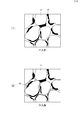
- FIG. 2 is an explanatory diagram of the state of the target formation MH.
- the target formation MH is a formation mainly composed of the sand particles 11, and it is assumed that the methane hydrate 13 exists in the gaps between the sand particles 11.
- methane hydrate since methane hydrate is in a stable region, it is in a solid state. Further, the sand particles are firmly fixed by the presence of solid methane hydrate. In this state, when the pressure is reduced, methane hydrate is decomposed into water and methane gas. Therefore, methane gas can be produced from methane hydrate by a decompression method. However, in this case, if no countermeasures are taken, the adhesion between the sand particles is lost due to the decomposition of methane hydrate, and the sand particles become fluid.
- an improving agent capable of sufficiently fixing the sand particles 11 is injected into the pores of the target formation MH, and the sand particles are artificially fixed.
- the target formation MH after improvement has a sufficient permeability for the production of methane hydrate, and even if methane hydrate is decomposed, the flow of sand particles, the formation of consolidation, and the occurrence of sand Has no properties.
- FIG. 3 is an explanatory diagram of injection of the improving agent G.
- the downhole injection device 109 has a main body, a connecting portion (hanging tool), an upper parka 71, and a lower parker 73, and is connected to a ground (or onboard) device through a hose 77.
- the main body has a hollow cylindrical shape, and an outflow hole through which a modifier and muddy water flows out is provided on a wall surface. It is also possible to use a dug pipe instead of the hose 77 depending on the working conditions.
- the injection of the modifier is carried out according to the following procedure. In some cases, the procedure may be different depending on the site conditions.
- the downhole injection device 109 is lowered to a predetermined depth.
- the upper parka 71 and the lower parker 73 are inflated by hydraulic pressure or compressed gas, and are brought into close contact with the inner wall of the casing 3.
- the improver G is fed through a hose (or drilling pipe) 77 into the downhole injection device.
- the improving agent G in the downhole injection device is filled between the upper parka 71 and the lower parker 73 from the outflow hole, and is eventually injected into the target formation MH through the gunper hole 31.
- the sand particles are fixed to each other via the solidified modifier G, and even if methane hydrate is decomposed, fluidization of the sand does not occur.
- it may be solidified in the hose (or the excavated pipe) 77 or the downhole injection device 109, and the device may become unusable again.
- the muddy water is circulated through a hose (or a drill pipe) 77 to discharge the improver G remaining in the apparatus.
- FIG. 4 is an example of the production flow of the present embodiment.
- Step 1 (planning process)>
- step 1 the type of injection improver, operation method and conditions, various parameters, etc. must be calculated and determined by production simulation, economic evaluation, etc., based on information on the geology of the development target, reservoir conditions, etc. No.
- the above information (a) and (b) can be obtained from the methane hydrate development business (oil company, etc.), as well as by independent exploration and measurement. It is also possible.
- Information (c) can be searched from the existing literature.
- Information (d) is available from the improver manufacturer or can be obtained in independent tests.
- the information (e) is one of the key points of the present invention, and is established by a unique experiment or simulation. Note that information other than the above may be required depending on the individual case.
- a plan for geological improvement is formulated by production simulation and economic evaluation.
- A Type of modifier
- b Optimal modification position and range. The range is expressed by the radius of improvement in the formation or the reach of the improver.
- C The concentration, use amount and compounding ratio of the improver.
- D Injection position, injection method, injection sequence, injection pressure, injection rate, etc.
- (m) Estimated methane gas and water production, Estimated transition of each parameter indicating the properties of the bed
- (n) the type of improver can be injected into the formation through a production well. Those that are possible and can sufficiently adhere the weakly consolidated sand particles that constitute the formation are selected. In some cases, it is also possible to switch to a different improver G in the middle.
- modifier G is produced by precipitation of cement, water glass, polymer (acrylamide, urea, urethane, etc.) or calcium carbonate and other precipitates, polymers, and other solids. It is assumed that a type that can fix sand particles is used.
- Step 2 an improving agent is injected into the target formation MH by a method as shown in FIG.
- the injection of the improving agent includes a pattern in which the target formation MH is entirely improved and a pattern in which only a part is improved.
- the target formation MH has properties similar to those of the conventional oil and gas reservoir (the property that sand particles are less likely to cause fluidity) by alternate injection and alternate production (described in FIG. 6). ) And has the advantage of making the most of existing oil and gas production technologies.
- the latter (partially improved) is a pattern in which the improving agent is injected into a limited area around the well (described with reference to FIG. 7).
- the improved formation acts as a filter that blocks only sand, such as water and methane gas, into the mine, while preventing sand from entering the periphery.
- This pattern has an advantage that the sand-prevention effect can be obtained and the improvement range (budget) can be minimized.
- Step 3 (hydraulic crushing and chemical treatment process)>
- Step 3 a well test is performed on the target formation MH improved in Step 2 to evaluate mainly the permeability and production capacity of the formation. If necessary, work is performed on the target formation MH to improve the permeability. For example, hydraulic crushing (a) or chemical treatment (b) is performed. Hydraulic crushing (a) is a technique for fracturing a shale layer with low permeability, mainly for the development of shale gas and shale oil. The test is performed for the improved part whose permeability has been greatly reduced by the reaction product.
- the chemical treatment (b) is an operation of mainly using hydrochloric acid or hydrofluoric acid to remove fine particles and the like in the pores and improve the permeability.
- the chemical treatment (b) is an operation of mainly using hydrochloric acid or hydrofluoric acid to remove fine particles and the like in the pores and improve the permeability.
- add a chemical that reacts with the relevant substance and promotes the product to be dissolved in liquid, gas or formation fluid it is also possible. If the target formation MH improved in step 2 has a sufficient permeability, this step need not be performed.
- Step 4 methane hydrate is decomposed by a decompression method or the like from the target formation MH improved in the above step, and methane gas is recovered. Also, based on the results of actual gas production, etc., the effectiveness of the geological improvement and the initial production plan are evaluated, which contributes to the formulation of a subsequent production plan and the development and improvement of the improving agent G.
- FIG. 5 is a conceptual diagram of a horizontal well when a plurality of horizontal wells 101 are used.
- the well 101 is provided with a horizontal portion 111 extending in the target formation MH.
- the horizontal part 111 is provided with a large number of gunper holes 31 as shown in FIG. 3, and it is possible to exchange a modifier or a product between the underground and the formation.
- a plurality of wells 101 are excavated side by side in the target formation MH in a certain direction in order to reliably improve the formation and maximize the production range.
- the well arrangement is not limited as shown in the figure, but is determined by the flow shown in FIG. 4 based on geological conditions, reservoir conditions, economic evaluation, and the like.
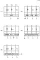
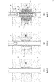
- FIG. 6 is a conceptual diagram in the case where the target formation MH is entirely improved by alternate injection / alternative production using a plurality of horizontal wells.
- FIG. 6A is an explanatory diagram of the first stage of the alternate injection. Depending on the condition of the reservoir, every other well 101 is divided into production wells and injection wells. Methane gas is produced from the second well 101b and the third well 101c by the decompression method while the improver G is injected from the first well 101a.
- FIG. 6B is an explanatory diagram of the second stage of the alternate injection.
- the process shifts to the second stage production shown in FIG. 6 (2).
- the first well 101a is switched to a methane gas production well
- the second well 101b and the third well 101c are switched to an injection well of the modifier G.
- the wells of both groups can be uniformly and stably improved to some extent without consolidation of the stratum or sand production.
- FIG. 6C is an explanatory diagram of the third stage of the alternate injection.
- the improvement of FIG. 6 (2) is advanced, as shown in FIG. 6 (3), in the second well 101b and the third well 101c, the improvement proceeds beyond the first well 101a of FIG. 6 (1). be able to.
- FIG. 6D is an explanatory diagram of a fourth stage of the alternate injection.
- the first well 101a switches to the injection well again as shown in FIG. 6 (4) and injects the improving agent.
- the second well 101b and the third well 101c are switched to the production wells again.
- the alternate injection and the alternate production are performed until the target formation MH is completely improved.
- FIG. 6 (5) is an explanatory view of the fifth stage of the alternate injection.
- the overall improvement of the target formation MH is completed, and the target formation MH has properties similar to those of a normal oil and gas reservoir. Since the formation of the formation is hardly confined or sand is produced, methane gas can be produced from all of the first well 101a, the second well 101b, and the third well 101c.
- FIG. 6 is merely an example.
- the number and shape of wells and the number of alternations of the improver injection can be changed according to the situation at the site. It is also possible to use an enhanced recovery method different from the decompression method.
- FIG. 7 is an explanatory diagram of a case where the target formation MH is partially improved by a single vertical well.
- the injection operation of the improving agent is performed using the downhole injection device of FIG.
- the improving agent diffuses around the well of the target formation MH having permeability, and artificially fixes the sand particles according to the principle shown in FIG. 2, so that formation consolidation and sand discharge do not occur during production.
- hydraulic fracturing and chemical treatment are performed on the improved body as necessary, and work is carried out to improve the permeability of the geologically improved section. In this way, an improved part having sufficient permeability and strength can be formed.
- the improved portion also functions as a filter that allows only fluid such as water or methane gas to flow into the mine while preventing sand from flowing in from the outer periphery.
- a sand improvement effect can be obtained by improving the formation only around the well, and at the same time, the budget for improving the formation can be minimized.
- a porous improvement body is formed by a filler in a target formation around a well to prevent sand from flowing down the mine during methane hydrate production.
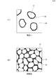
- FIG. 8 is a conceptual diagram of forming a porous improved body with a filler according to the second embodiment of the present invention.
- the filler in the present invention is a material formed by coating the surface of the particles 21 with the fixing agent 22.
- the particles 21 are silica sand, ceramic, and glass beads having a diameter of 0.1 mm to 10 mm.
- the fixing agent 22 is solid at room temperature and in a dry state, but causes a chemical reaction by heat, water, a compounding agent or a catalyst to generate solids such as calcium carbonate and a polymer substance, thereby fixing the particles 21.
- the filler is dispersed in the liquid 24 serving as the carrier medium, and a liquid or slurry-like injection material having appropriate viscosity is produced.
- This injection material is sent into the mine by an underground injection device and injected into the cavity of the target formation. The injected filling material allows the liquid 24 to permeate into the target formation, and the remaining filling material can fill the cavities so that the particles come into close contact with each other.
- the filling rate of the cavity can be estimated from the injection amount, injection rate, injection pressure, and the like of the injection material.
- the filler is selected from those capable of forming an improved body having sufficient strength and good permeability in a stratum environment where methane hydrate is present.
- it is selected from resin-coated sand (resin-coated sand), resin-coated ceramic particles, resin-coated glass beads, and sand, glass beads, or ceramic particles coated on the surface with the above-described modifier.
- the liquid 24 serving as the transport medium is muddy water or other liquid whose specific gravity is adjusted to balance with the formation pressure and whose viscosity is adjusted so that the dispersed filler does not easily settle.
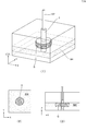
- FIG. 9 is an explanatory diagram of a method of forming an improved body around a well according to the second embodiment of the present invention.
- a well is excavated to the target formation MH.
- the casing 3 is installed in the mine, and cementing is performed between the pit wall and the casing 3.
- the casing 3 and the cementing portion are provided with a plurality of gunper holes 31 penetrating the casing and the target formation MH. Through the gunper holes 31, material (fluid and also solid particles) exchange between the formation and the casing is possible.
- Construction of the improved body is performed in the following procedure. -Decompression by the submersible pump (ESP pump) 41 is performed to decompose methane hydrate contained in the target formation MH.
- ESP pump submersible pump
- the sand particles constituting the stratum lose their sticking power, are transported into the pit with the production of water, and are discharged to the ground (on board) by the submersible pump 41. Due to the sand discharge, a cavity C filled with the formation fluid is formed in the target formation MH around the well.
- On the ground (on board) monitor the discharge rate and accumulated discharge of sand and water, and monitor the estimated scale (height, radius, etc.) of the cavity formed around the well.
- the sand discharging operation is stopped, and the submersible pump 41 is collected to the ground (or on board).
- Hot water and compounding agent that promote the solidification of the filler and the filler F into the cavity formed by the sand similarly to the method of injecting the improver in the first embodiment, using the underground injection device of FIG. Or inject the catalyst.
- water or muddy water is circulated through a hose (or a dug pipe) 77 to discharge the remaining injection material in the injection device.
- ⁇ Recover the underground injection device to the ground (or on board).
- the filler F can be injected into the target formation around the well.
- the filler F becomes a porous improved body having sufficient strength and good permeability, and can realize stable gas production while preventing sand erosion.
- methane hydrate may be decomposed by hot water circulation or by inputting a chemical substance such as an inhibitor, other than decompression by a submersible pump.
- a method of forming a cavity in the target formation in addition to the method of decomposing methane hydrate, formation cutting by high-pressure fluid injection or formation cutting by a machine fed into a pit may be used.
- a method of injecting the filler into the formation cavity other than the downhole injection device of FIG. 3, other devices or construction methods may be used. With such an embodiment, it is possible to prevent sand from being produced more than necessary when producing methane hydrate.
- the structure, system, program, material, connection of each member, used chemical substance, and the like of the present invention can be variously changed without changing the gist of the present invention.
- the material can be freely selected from metals, plastics, composite materials, ceramics, concrete and the like.
- two or more members can be made into one, or conversely, one member can be made up of two or more other members and connected.
- the improver may be used in combination with additives (adsorption accelerators, surfactants, catalysts, etc.) for making the improver work effectively, or may be used to impart permeability to the improved formation. Bubbles of gas such as N2 or CO2 or microvalves may be mixed with the improver.
- the improvement is not limited to one time for one formation, and the improvement may be performed at a plurality of locations in multiple stages. Conversely, it is also possible to carry out the improvement on a plurality of thin layers at once.
- the above-described embodiment is merely one of the best modes at present.
- the control may be controlled by a control unit on an excavation ship or a ground site, or may be controlled by a control unit installed in the sea, at a pit, or in a pit. Also, the order of the steps and the like can be appropriately changed as long as they have a predetermined effect.
Landscapes
- Engineering & Computer Science (AREA)
- Geology (AREA)
- Life Sciences & Earth Sciences (AREA)
- Mining & Mineral Resources (AREA)
- Geochemistry & Mineralogy (AREA)
- Fluid Mechanics (AREA)
- Environmental & Geological Engineering (AREA)
- General Life Sciences & Earth Sciences (AREA)
- Physics & Mathematics (AREA)
- Chemical & Material Sciences (AREA)
- Oil, Petroleum & Natural Gas (AREA)
- Chemical Kinetics & Catalysis (AREA)
- General Chemical & Material Sciences (AREA)
- Organic Chemistry (AREA)
- Consolidation Of Soil By Introduction Of Solidifying Substances Into Soil (AREA)
- Soil Conditioners And Soil-Stabilizing Materials (AREA)
Abstract
Description
(a)開発対象となるメタンハイドレート地層内に改良剤または充填材を注入する地層改良工程。
(b)前記地層改良工程(a)の前に、注入改良剤の種類、操業の方法と条件及び諸パラメータ等の算出、決定する計画工程。
(c)前記地層改良工程(a)の後に、地層改良を施した地層からメタンハイドレートをメタンガスと水に分解させ、メタンガスを回収する生産工程。
(d)前記地層改良工程(a)の後、前記生産工程(c)の前に、必要に応じて、地層改良を施した地層の浸透率を向上させる、水圧破砕及びケミカル処理工程。
(e)前記計画工程(b)の後、前記地層改良工程(a)の前に、充填材により改良体を造成するスペースを作るために、予め出砂を意図的に起こし、空洞を作る前処理工程。
上記(a)~(e)の工程のうち、経済性の最大化のために、一部の工程を省略したり、複数回を実施したり、または実施手順を変えてもよい。
好適には、前記充填材は、自然または人工出砂によりできた空洞に、十分な強度と良好な浸透性を有する改良体を造成できるものから選ばれる。例えば、樹脂被覆プロパント、樹脂被覆セラミック粒、樹脂被覆ガラスビーズ、及び前記改良剤を表面にコーティングした砂、ガラスビーズまたはセラミック粒子から選ばれる。
好適には、地層に改良剤または充填材を注入する工法として、改良剤を砂粒子の間隙を浸透させる薬液注入工法と、高圧のジェット流により砂を切削し、改良剤または充填材を強制的に地層に注入する高圧噴射工法を採用する。
また、本発明により改良後のメタンハイドレートの地層は、従来の石油・ガス貯留層と類似した性質を持つようになり、既存の石油・ガス開発技術を最大限に活用でき、経済面で有利である。
図1は、本発明の第1の実施形態に係る生産方法の説明図である。
作業船1には、改良剤タンク102、ポンプ103、ウインチ104、泥水処理装置105が搭載されている。ウインチ104は、注入用ホース107を巻き取って収納しており、必要に応じて伸ばしたり巻き取ったりすることができる。注入用ホース107は、改良剤タンク102内の改良剤Gを送り込むために使用される。また作業条件により、ホースの代わりに掘管を使うことも可能である。
他方、泥水ホース106は、坑井内から戻ってきた泥水を作業船1へ輸送するために使用される。泥水ホース106からの泥水は、泥水処理装置105で適切な処理が行われる。
坑内注入装置109は、対象地層に改良剤を注入するために使われる。
ただし、これはあくまで一例である。これに限定されず、深度が異なる海底、地層でも、又は異なる層厚を有する対象地層MHでも応用可能である。また、対象地層MHにケーシングを設置せず、坑壁に他の支保対策または裸坑での生産も可能である。更に、本方法は、海底の対象地層MHだけではなく、陸上のメタンハイドレート地層に対しても応用可能である。
この状態において、圧力を下げると、メタンハイドレートは水とメタンガスに分解するため、減圧法によってメタンハイドレートからメタンガスを生産することが可能である。
しかし、この場合何も対策をしないと、メタンハイドレートの分解により、砂粒子間の固着力が喪失し、砂粒子に流動性が生じてしまう。その結果、メタンガスや水と共に、砂11も大量に流出することになり、大きな生産障害となる。
そこで、メタンハイドレートの安定生産の為に、対象地層MHの浸透率が大きく下がらない範囲で、砂11の流出を防ぐことができる方法が求められている。
本発明における地層改良は、砂粒子11を十分に固着できる改良剤を対象地層MHの孔隙に注入し、砂粒子を人工的な固着する。注入条件のコントロールにより、改良後の対象地層MHはメタンハイドレートの生産に十分な浸透率を有し、かつ、メタンハイドレートが分解しても、砂粒子の流動や地層圧密、出砂が起こらない性質を有する。
坑内注入装置109は、本体、連結部(吊り具)、上側パーカ71、下側パーカ73を有しており、ホース77を通じて地上(または船上)装置まで繋ぐ。本体は中空の円筒状であり、壁面に改良剤や泥水が出る流出孔が設けられる。なお、作業条件により、ホース77の代わりに掘管を使うことも可能である。
・上側パーカ71及び下側パーカ73が収縮した状態で、坑内注入装置109を所定の深度まで降下させる。
・油圧または圧縮気体により、上側パーカ71及び下側パーカ73を膨らませ、ケーシング3の内壁と密着させる。
・地上(又は船上)設備から、改良剤Gをホース(または掘管)77を通して坑内注入装置に送り込む。坑内注入装置内の改良剤Gは、流出孔から上側パーカ71及び下側パーカ73の間に充満され、やがてガンパー孔31を通じて対象地層MHに注入される。
・改良剤Gのゲルタイムを経つと、砂粒子同士は固化した改良剤Gを介して固着され、メタンハイドレートが分解しても、砂に流動化が生じなくなる。
なお、改良剤の種類やゲルタイムにより、ホース(または掘管)77や坑内注入装置109内に固化し、該当装置を再度使用不能に陥る可能性がある。その場合、改良剤注入が完了後に、ホース(または掘管)77を通じて泥水を循環させ、装置内に残余した改良剤Gを排出する。
ステップ1では、開発対象の地質、貯留層条件等の情報に基づいて、生産シミュレーションや経済性評価等により、注入改良剤の種類、操業の方法と条件及び諸パラメータ等を算出、決定しなければならない。
上記の計画工程では、予め、下記情報(a)~(e)の全部又は一部を入力データ又は判断材料として知っておく必要がある。
(a)地質構造、地層連続性、岩相、粒径、推定可採埋蔵量
(b)貯留層の形状、境界、各所の深度、層厚、孔隙率、浸透率、飽和率、温度、圧力
(c)メタンハイドレートの安定領域、分解条件
(d)各改良剤の適用対象、適用条件、適用限界
(e)各改良剤の反応メカニズム、及び反応の進行に伴う、温度、圧力、孔隙率、各相流体の飽和率、浸透率の定量的な変化等
上記の情報(a)、(b)は、メタンハイドレートの開発事業体(石油会社等)から入手できるほか、独自で探査、測定することも可能である。情報(c)は、既往文献から調査できる。情報(d)は、改良剤メーカーから入手できるほか、独自の試験で得ることもできる。情報(e)は、本発明のキーポイントの一つであり、独自の実験又はシミュレーションにより確立するものである。
なお、個別案件により、上記以外の情報を必要とすることもある。
(a)改良剤の種類
(b)最適な改良位置と範囲。範囲は、地層内の改良半径又は改良剤到達範囲で表す
(c)改良剤の濃度、使用量と配合比
(d)改良剤の注入位置、注入工法、注入順序、注入圧力、注入レート等
(e)改良剤の最適なゲルタイム
(f)改良剤と配合使用する添加材の種類、濃度、使用量、使用タイミング等
(g)改良剤反応による生成物の種類、質量、濃度、化学特性、濡れ性等
(h)改良後の対象地層MHの浸透率、孔隙率、圧力、温度、強度等
(i)残りの未反応改良剤の量、濃度、粘性との変化傾向
(j)改良後の地層流体の組成、粘性、pH等
(k)未反応の改良剤を排出する為の作業工法、泥水の密度、粘性、泥水循環レート等
(l)対象地層の浸透率の回復作業の必要性の有無、及びその作業の種類、方法等
(m)メタンガスや水の見込み生産量、地層の性状を表す各パラメータの見込み推移
(n)上記の条件やパラメータによる操業コスト、経済性を表す諸指標
上記のうち、(a)改良剤の種類は、生産井を通して地層に注入することが可能であり、かつ、地層を構成する固結の弱い砂粒子を十分に固着できるものが選定される。また、場合によって、途中から異なる改良剤Gに切り替えることも可能である。
現在のところ、改良剤Gは、セメント系、水ガラス系、高分子系(アクリルアミド系、尿素系、ウレタン系等)、又は炭酸カルシウムをはじめとする沈殿、ポリマー、及びその他の固形物の生成により、砂粒子を固着できるタイプを用いることを想定している。
ただし、上記の種類に限定されず、今後より良いものを開発予定である。開発の際にも、生産井を通して地層に注入することが可能であり、かつ、地層を構成する固結の弱い砂粒子を十分に固着できるという観点で選択することになる。
ステップ2において、対象地層MHに、図3に示すような方法で改良剤を注入する。
改良剤の注入は、対象地層MHを全面改良するパターンと、一部のみ改良するパターンがある。前者(全面改良)は、交互注入・交互生産(図6にて説明する)により、対象地層MHが従来の石油・ガスの貯留層と似たような性質(砂粒子に流動性を生じにくい性質)を持つように改良し、既存を石油・ガスの生産技術を最大限に活用できる利点がある。
一方、後者(一部改良)は、坑井周辺の限られた範囲に改良剤を注入するパターン(図7にて説明する)である。改良された地層は、外周からの砂流入を阻止しつつ、水やメタンガス等の流体のみが坑内に入れるフィルターのような役割を果たす。このパターンは、出砂防止効果を得られると同時に、改良範囲(予算)を最小限に抑えられる利点がある。
ステップ3において、上記ステップ2で改良された対象地層MHを対象に、坑井テストを実施し、主に地層の浸透率や生産能力を評価する。必要に応じ、対象地層MHを対象に浸透率を向上させる作業を行う。例えば、水圧破砕(a)又はケミカル処理(b)を行う。
水圧破砕(a)は本来、主にシェールガスやシェールオイルの開発の為に、浸透率の低い頁岩層に割れ目を作る(フラクチャリング)技術であるが、本発明においては、改良剤の固化または反応生成物により浸透率が大きく下がった改良部を対象に実施する。
一方、ケミカル処理(b)は、主に塩酸またはフッ酸を利用し、孔隙内の細粒分等を除去し、浸透率を向上させる作業である。その他、地層改良過程における過剰反応物や反応の副生成物による浸透率の低下を解消するために、該当物質と反応し、生成物は液体、気体または地層流体に溶けるように促す薬剤を投入することも可能である。
なお、上記ステップ2で改良が施された対象地層MHは十分な浸透率を有する場合、このステップを実施しなくてもよい。
ステップ4において、上記ステップにより改良された対象地層MHから、減圧法等によりメタンハイドレートを分解させ、メタンガスを回収する。
また、実際のガス生産の実施結果などから、地層改良の有効性や当初の生産計画を評価し、後続生産計画の策定や改良剤Gの開発・改良に資する。
なお、実際の開発では、坑井配置は図示のように限定されず、地質条件、貯留層条件や経済性評価等に基づき、図4に示すフローにより決められる。
貯留層の条件により、坑井101を1本おきに、生産井、注入井とグループに分ける。
第1坑井101aから、改良剤Gを注入しつつ、第2坑井101b及び第3坑井101cから、減圧法によりメタンガスの生産を行う。
図6(1)のように、第2坑井101b及び第3坑井101cから生産を続けると、地層の圧密や出砂の懸念が生ずる。そこで、ある程度メタンハイドレートが分解した段階で、図6(2)に示す第2段階の生産に移行する。
具体的には、第1坑井101aをメタンガスの生産井に切り替え、第2坑井101b及び第3坑井101cを改良剤Gの注入井に切り替える。これにより、両グループの坑井とも、地層の圧密や出砂が生じずに、ある程度均一で安定的に改良することができる。
図6(2)の改良を進めると、図6(3)のように、第2坑井101b及び第3坑井101cにおいて、図6(1)の第1坑井101aより上回る改良範囲まで進めることができる。
第1坑井101aは、ある程度メタンハイドレートが分解した後、図6(4)のように再度注入井に切り替え、改良剤を注入する。一方、第2坑井101b及び第3坑井101cは、再度、生産井に切り替える。このように、対象地層MHが全面改良されるまで、交互注入・交互生産を実施する。
図6(4)まで進むと、対象地層MHの全面改良が完了し、通常の石油・ガス貯留層と相似した性質を持つようになる。地層の圧密や出砂を生じにくくなるので、第1坑井101a、第2坑井101b、第3坑井101cの全てからメタンガスの生産が可能となる。
なお、図6はあくまで一例である。坑井本数や形態、改良剤注入の交互回数は、現場の状況に合わせ変更可能である。また、減圧法とは異なる増進回収法の利用も可能である。
対象地層MHを通す垂直坑井(101)の適切深度において、図3の坑内注入装置を用いて改良剤の注入作業を行う。この際、改良剤は浸透性を有する対象地層MHの坑井周辺に拡散し、図2に示す原理で砂粒子を人工的に固着し、生産時の地層圧密や出砂が生じなくなる。その後、改良体を対象に、必要に応じて水圧破砕(フラクチャリング)やケミカル処理を行い、地層改良部の浸透率を向上させる作業を行う。このように、十分な浸透率と強度を有する改良部を造成できる。
この改良部は、外周からの砂流入を阻止しつつ、水やメタンガス等の流体のみが坑内に流入できるフィルターのような役割も果たす。坑井周辺のみの地層改良で出砂防止効果を得られると同時に、地層改良に使う予算を最小限に抑えることができる。
本発明の第2の実施形態では、坑井周辺の対象地層において充填材により多孔質改良体を造成し、メタンハイドレート生産時における坑内出砂を防ぐ。
図8は、本発明の第2の実施形態に係る、充填材による多孔質改良体造成の概念図である。
本発明における充填材は、粒子21の表面に固着剤22をコーティングして作られた材料である。粒子21は、直径0.1mm~10mmの珪砂、セラミック、ガラスビーズである。固着剤22は、常温、乾燥状態において固体であるが、熱、水、配合剤または触媒により化学反応が起こり、炭酸カルシウムや高分子物質等の固形物を生成することにより、粒子21を固着する性質を有する。
充填する際は、充填材をその運搬媒体となる液体24に分散させ、適切な粘性を有する液状またはスラリー状の注入材を作製する。この注入材を坑内注入装置により坑内に送り込み、対象地層の空洞に注入する。注入された注入材は、液体24が対象地層に浸透していき、残りの充填材は粒と粒が密着するように空洞を充填できる。注入材の注入量、注入レート、注入圧等から、空洞の充填率を推定できる。
空洞が十分に充填されれば、固着材22による化学反応を促進する熱水、配合剤または触媒を地層に注入する。これにより、固着材22により化学反応が起こり、固形物を生成し、粒子21を固着できる。固着された粒子21同士の間に孔隙23を有しており、流体を通すことができる。これにより、十分な強度と良好な浸透性を有する多孔質改良体を作成でき、出砂を防止しつつ、安定したガス生産を実現できる。
好適には、前記充填材は、メタンハイドレートが賦存する地層環境において、十分な強度と良好な浸透性を有する改良体を造成できるものから選ばれる。例えば、樹脂被覆砂(レジンコーテッドサンド)、樹脂被覆セラミック粒、樹脂被覆ガラスビーズ、及び前記改良剤を表面にコーティングした砂、ガラスビーズまたはセラミック粒子から選ばれる。
好適には、前記運搬媒体となる液体24は、地層圧力とのバランスをとるために比重を調整した、かつ、分散された充填材が容易に沈殿しないように粘度を調整した泥水または他の液体を使用する。
図9のように、対象地層MHまで坑井を掘削する。坑内にケーシング3を設置し、坑壁とケーシング3の間にセメンチングが施されている。また、ケーシング3及びセメンチング部には、ケーシング内と対象地層MHを貫通する複数のガンパー孔31が開けられている。ガンパー孔31を通して、地層とケーシング内との物質(流体はまた固形粒子)交換が可能になる。
改良体の造成は、以下の手順で実施する。
・水中ポンプ(ESPポンプ)41による減圧を実施し、対象地層MHに含まれるメタンハイドレートを分解させる。メタンハイドレートの分解に伴い、地層を構成する砂粒子は固着力を喪失し、水の産出に伴い坑内に運搬され、水中ポンプ41により地上(船上)に排出される。砂の排出により、坑井周辺の対象地層MHに地層流体で充満された空洞Cが形成される。
・地上(船上)において、砂と水の排出レートや累積排出量を監視し、坑井周辺に形成された空洞の推定規模(高さ、半径等)をモニタリングする。
・空洞の推定規模が計画値に達すれば、砂排出作業を中止し、水中ポンプ41を地上(または船上)まで回収する。
・図3の坑内注入装置を用い、第1の実施形態における改良剤の注入方法と同様に、出砂で形成された空洞に注入材、及び充填材Fの固化を促進する熱水、配合剤または触媒を注入する。
・注入作業が完了後、ホース(または掘管)77を通じて水または泥水を循環させ、注入装置内に残余した注入材を排出する。
・坑内注入装置を地上(または船上)まで回収する。
これにより、坑井周辺の対象地層に充填材Fを注入できる。充填材Fは固結後、十分な強度と良好な浸透性を有する多孔質改良体になり、出砂を防止しつつ、安定したガス生産を実現できる。
なお、前記意図的に出砂を起こす手法として、水中ポンプによる減圧以外、熱水循環やインヒビター等化学物質の投入によりメタンハイドレートを分解させてもよい。また、対象地層に空洞を作る手法として、前記メタンハイドレートを分解させる手法以外に、高圧流体噴射による地層切削や、坑内に送り込む機械による地層切削を用いてもよい。更に、充填材を地層空洞に注入する方法として、図3の坑内注入装置以外に、他の装置や工法を用いてもよい。
このような実施形態を有することから、メタンハイドレートの生産の際に砂を必要以上に生産することを防ぐことが可能となる。
材質も、金属、プラスチック、複合材、セラミック、コンクリート等を自由に選択することが可能である。
例えば、2つ以上の部材を1つにすることも可能であるし、逆に、1つの部材を2つ以上の別の部材から構成して接続することも可能である。
また、改良剤には、改良剤をうまく効かせるための添加剤(吸着促進剤、界面活性剤、触媒等)を配合使用しても、または、改良後の地層に滲透性を持たせるよう、改良剤にN2やCO2等ガスの気泡やマイクロバルブを混和しても良い。
また、一つの地層に対して一回の改良に限らず、複数の箇所で多段階で改良を実施しても良い。逆に、複数の薄層に対して一括で改良を実施することも可能である。
また、上記実施形態は、あくまでも、現在のところの最良の形態の1つにすぎない。
また、制御などは、掘削船や地上現場の制御部分によって制御されても良いし、海中、坑口、坑内 に設置する制御部分によって制御されても良い。
また、工程の順序なども、所定の効果を有するのであれば、適宜変更可能である。
3 :ケーシング
7 :坑内注入装置
11 :砂粒子
13 :メタンハイドレート
21 :充填材の粒子
22 :充填材の固着剤
23 :孔隙
24 :充填材の運搬媒体となる液体
31 :ガンパー孔
41 :水中ポンプ
71 :上側パーカ
74 :孔
73 :下側パーカ
75 :坑内注入装置本体
77 :ホース
79 :連結部
101:坑井
102:改良剤タンク
103:ポンプ
104:ウインチ
105:泥水処理装置
106:泥水ホース
107:注入用ホース
108:BOP(防噴装置)
109:坑内注入装置
111:水平部
C :空洞
F :充填材
MH :対象地層
G :改良剤
Claims (13)
- 陸上の凍土層又は海底地層の砂粒子間に存在するメタンハイドレートを対象とし、前記対象地層内に改良剤を注入する地層改良工程を有する生産手法。
- 陸上の凍土層又は海底地層の砂粒子間に存在するメタンハイドレートを対象とし、前記対象地層内に自然または人工で発生した空洞に、充填材を注入し改良体を作る地層改良工程を有する生産手法。
- 前記地層改良工程の前に、注入改良剤または充填材の種類、操業の方法と条件及び各パラメータ等の算出、決定する計画工程を有し、前記地層改良工程は、前記計画工程で決定された条件等で改良剤または充填材を注入する請求項1と請求項2に記載の生産方法。
- 前記地層改良工程の後に、地層改良を施した地層からメタンハイドレートをメタンガスと水に分解させ、メタンガスを回収する生産工程を有する生産手法。
- 前記地層改良工程の後に、必要に応じて、地層改良を施した地層の浸透率を向上させる、水圧破砕又はケミカル処理工程を有する請求項4に記載の生産方法。
- 前記計画工程では、少なくとも、改良剤または充填材の種類を決定する請求項3に記載の生産方法。
- 前記改良剤は、生産井を通して地層に注入することが可能であり、かつ、地層を構成する固結の弱い砂粒子を十分に固着できるものから選ばれる請求項6に記載の生産方法。
- 前記改良剤は、セメント系、水ガラス系、高分子系(アクリルアミド系、エポキシ樹脂、フェノール樹脂、フラン樹脂系、尿素系、ウレタン系等)、又は炭酸カルシウムをはじめとする沈殿、ポリマー、及びその他の固形物の生成により、砂粒子を固着できるタイプの改良剤から選ばれる請求項7に記載の生産方法。
- 前記充填剤は、生産井を通して地層に注入することが可能であり、かつ、十分な強度と良好な浸透性を有する改良体を作成できるものから選ばれる請求項6に記載の生産方法。
- 前記充填剤は、樹脂被覆砂(レジンコーテッドサンド)、樹脂被覆セラミック粒、樹脂被覆ガラスビーズ、及び請求項8に記載の改良剤を表面にコーティングした砂、ガラスビーズ、セラミック粒子または他の粒子状物質から選ばれる請求項9に記載の生産方法。
- 前記計画工程では、少なくとも、改良剤または充填材の注入に伴う地層の挙動を含むシミュレーションをし、注入の条件を決定する請求項3に記載の生産方法。
- 前記計画工程では、少なくとも、請求項1に記載の生産方法により改良を施した地層からメタンガスを生産するシミュレーションをし、注入の条件を決定する請求項3に記載の生産方法。
- 前記計画工程では、少なくとも、請求項2に記載の生産方法により改良を施した地層からメタンガスを生産するシミュレーションをし、注入の条件を決定する請求項3に記載の生産方法。
Priority Applications (4)
| Application Number | Priority Date | Filing Date | Title |
|---|---|---|---|
| CA3104775A CA3104775A1 (en) | 2018-06-25 | 2018-09-11 | Production method for methane hydrate using reservoir grouting |
| US17/256,014 US11492884B2 (en) | 2018-06-25 | 2018-09-11 | Production method for methane hydrate using reservoir grouting |
| CN201880095034.XA CN112912589A (zh) | 2018-06-25 | 2018-09-11 | 基于地层改造的甲烷水合物开采方法 |
| JP2020527171A JP7170725B2 (ja) | 2018-06-25 | 2018-09-11 | 地層改良を用いたメタンハイドレートの生産方法。 |
Applications Claiming Priority (2)
| Application Number | Priority Date | Filing Date | Title |
|---|---|---|---|
| JP2018-119449 | 2018-06-25 | ||
| JP2018119449 | 2018-06-25 |
Publications (1)
| Publication Number | Publication Date |
|---|---|
| WO2020003551A1 true WO2020003551A1 (ja) | 2020-01-02 |
Family
ID=68986205
Family Applications (1)
| Application Number | Title | Priority Date | Filing Date |
|---|---|---|---|
| PCT/JP2018/033532 Ceased WO2020003551A1 (ja) | 2018-06-25 | 2018-09-11 | 地層改良を用いたメタンハイドレートの生産方法。 |
Country Status (5)
| Country | Link |
|---|---|
| US (1) | US11492884B2 (ja) |
| JP (1) | JP7170725B2 (ja) |
| CN (1) | CN112912589A (ja) |
| CA (1) | CA3104775A1 (ja) |
| WO (1) | WO2020003551A1 (ja) |
Cited By (3)
| Publication number | Priority date | Publication date | Assignee | Title |
|---|---|---|---|---|
| WO2020250893A1 (ja) * | 2019-06-10 | 2020-12-17 | E&P国際商事株式会社 | ガスハイドレート層への薬剤注入効果及び安定化効果の向上方法 |
| CN117248870A (zh) * | 2023-10-09 | 2023-12-19 | 中国石油大学(北京) | 一种冻土区天然气水合物提高采收率方法 |
| US12618301B2 (en) | 2022-02-28 | 2026-05-05 | National Institute Of Advanced Industrial Science And Technology | Joint assembly, production well manufacturing method, and gas production method |
Families Citing this family (1)
| Publication number | Priority date | Publication date | Assignee | Title |
|---|---|---|---|---|
| CN113417596B (zh) * | 2021-08-24 | 2021-11-12 | 中国石油大学(华东) | 天然气水合物地层层内加固防塌、防砂理论及实现方法 |
Citations (2)
| Publication number | Priority date | Publication date | Assignee | Title |
|---|---|---|---|---|
| JP2003214082A (ja) * | 2002-01-18 | 2003-07-30 | Tobishima Corp | ガスハイドレート掘採方法とその装置 |
| JP2006214164A (ja) * | 2005-02-03 | 2006-08-17 | Kajima Corp | 地下資源の回収施設 |
Family Cites Families (6)
| Publication number | Priority date | Publication date | Assignee | Title |
|---|---|---|---|---|
| US4549608A (en) * | 1984-07-12 | 1985-10-29 | Mobil Oil Corporation | Hydraulic fracturing method employing special sand control technique |
| US6978837B2 (en) * | 2003-11-13 | 2005-12-27 | Yemington Charles R | Production of natural gas from hydrates |
| US7404441B2 (en) * | 2006-02-27 | 2008-07-29 | Geosierra, Llc | Hydraulic feature initiation and propagation control in unconsolidated and weakly cemented sediments |
| JP4852492B2 (ja) | 2007-07-27 | 2012-01-11 | 日本海洋掘削株式会社 | メタンハイドレートの分解促進およびメタンガス採取システム |
| JP5067814B2 (ja) | 2009-07-02 | 2012-11-07 | 独立行政法人産業技術総合研究所 | メタンハイドレート分解方法及び装置 |
| JP2015187222A (ja) * | 2014-03-26 | 2015-10-29 | 住友ベークライト株式会社 | 樹脂組成物、被覆粒子、注入剤および充填方法 |
-
2018
- 2018-09-11 JP JP2020527171A patent/JP7170725B2/ja active Active
- 2018-09-11 CN CN201880095034.XA patent/CN112912589A/zh active Pending
- 2018-09-11 US US17/256,014 patent/US11492884B2/en active Active
- 2018-09-11 WO PCT/JP2018/033532 patent/WO2020003551A1/ja not_active Ceased
- 2018-09-11 CA CA3104775A patent/CA3104775A1/en active Pending
Patent Citations (2)
| Publication number | Priority date | Publication date | Assignee | Title |
|---|---|---|---|---|
| JP2003214082A (ja) * | 2002-01-18 | 2003-07-30 | Tobishima Corp | ガスハイドレート掘採方法とその装置 |
| JP2006214164A (ja) * | 2005-02-03 | 2006-08-17 | Kajima Corp | 地下資源の回収施設 |
Cited By (3)
| Publication number | Priority date | Publication date | Assignee | Title |
|---|---|---|---|---|
| WO2020250893A1 (ja) * | 2019-06-10 | 2020-12-17 | E&P国際商事株式会社 | ガスハイドレート層への薬剤注入効果及び安定化効果の向上方法 |
| US12618301B2 (en) | 2022-02-28 | 2026-05-05 | National Institute Of Advanced Industrial Science And Technology | Joint assembly, production well manufacturing method, and gas production method |
| CN117248870A (zh) * | 2023-10-09 | 2023-12-19 | 中国石油大学(北京) | 一种冻土区天然气水合物提高采收率方法 |
Also Published As
| Publication number | Publication date |
|---|---|
| US20210222536A1 (en) | 2021-07-22 |
| US11492884B2 (en) | 2022-11-08 |
| JPWO2020003551A1 (ja) | 2021-08-12 |
| CA3104775A1 (en) | 2020-01-02 |
| CN112912589A (zh) | 2021-06-04 |
| JP7170725B2 (ja) | 2022-11-14 |
Similar Documents
| Publication | Publication Date | Title |
|---|---|---|
| US4300633A (en) | Method of cementing wells with foam-containing cement | |
| CN106761588B (zh) | 射流破碎、反循环输送浆态海洋天然气水合物的开采方法及开采装置 | |
| RU2231631C1 (ru) | Способ разработки нефтяной залежи | |
| JP2019533776A (ja) | シルト質海洋天然ガスハイドレート砂利呑吐採掘方法及び採掘装置 | |
| Torsæter et al. | Geological and geomechanical factors impacting loss of near-well permeability during CO2 injection | |
| CN106837257B (zh) | 一种海洋非成岩天然气水合物藏开采系统及其开采工艺 | |
| MXPA04004688A (es) | Metodo y aparato para un pozo barrenado de monodiametro, una cubierta de monodiametro, un monoagujero y/o monopozo. | |
| US9879401B2 (en) | Oil and gas well and field integrity protection system | |
| CN101248162A (zh) | 气体水化物的生成方法、置换方法以及采掘方法 | |
| CA2649850A1 (en) | Method of drilling from a shaft for underground recovery of hydrocarbons | |
| KR101382753B1 (ko) | 저류 물질의 저류 장치 및 저류 방법 | |
| US6715543B1 (en) | Particulate matter plug for plugging a well | |
| US5489740A (en) | Subterranean disposal of wastes | |
| JP2009274047A (ja) | 炭酸ガスの地中貯留システム | |
| JP7170725B2 (ja) | 地層改良を用いたメタンハイドレートの生産方法。 | |
| US20230272696A1 (en) | Method for deep-sea extraction of natural gas hydrates with reservoir top control and sand prevention | |
| US3696867A (en) | Resin consolidated sandpack | |
| Minton et al. | Annular re-injection of drilling wastes | |
| CN110656947A (zh) | 海底基岩凸起段的掘进方法 | |
| RU2529197C1 (ru) | Способ подземного захоронения буровых отходов | |
| RU2282712C2 (ru) | Способ ликвидации скважины | |
| US10184324B2 (en) | Wellbore lining for natural gas hydrate and method of constructing a wellbore lining for natural gas hydrate | |
| RU2231632C1 (ru) | Способ разработки нефтяной залежи | |
| RU2132467C1 (ru) | Способ изоляции подземного хранилища токсичных отходов в соленосных породах | |
| JP7016077B2 (ja) | ガスハイドレート採掘装置および採掘方法 |
Legal Events
| Date | Code | Title | Description |
|---|---|---|---|
| 121 | Ep: the epo has been informed by wipo that ep was designated in this application |
Ref document number: 18924162 Country of ref document: EP Kind code of ref document: A1 |
|
| ENP | Entry into the national phase |
Ref document number: 2020527171 Country of ref document: JP Kind code of ref document: A |
|
| ENP | Entry into the national phase |
Ref document number: 3104775 Country of ref document: CA |
|
| NENP | Non-entry into the national phase |
Ref country code: DE |
|
| 122 | Ep: pct application non-entry in european phase |
Ref document number: 18924162 Country of ref document: EP Kind code of ref document: A1 |