WO2019245004A1 - Équipement utilisateur et son procédé de communication - Google Patents
Équipement utilisateur et son procédé de communication Download PDFInfo
- Publication number
- WO2019245004A1 WO2019245004A1 PCT/JP2019/024604 JP2019024604W WO2019245004A1 WO 2019245004 A1 WO2019245004 A1 WO 2019245004A1 JP 2019024604 W JP2019024604 W JP 2019024604W WO 2019245004 A1 WO2019245004 A1 WO 2019245004A1
- Authority
- WO
- WIPO (PCT)
- Prior art keywords
- congestion management
- identification information
- pdu session
- network
- management
- Prior art date
Links
- 238000000034 method Methods 0.000 title claims abstract description 465
- 238000004891 communication Methods 0.000 title claims abstract description 72
- 230000005540 biological transmission Effects 0.000 abstract description 42
- 238000007726 management method Methods 0.000 description 757
- 230000008569 process Effects 0.000 description 111
- 230000006399 behavior Effects 0.000 description 98
- 230000006870 function Effects 0.000 description 75
- 238000012545 processing Methods 0.000 description 61
- 230000008859 change Effects 0.000 description 56
- 238000010295 mobile communication Methods 0.000 description 25
- 230000007420 reactivation Effects 0.000 description 24
- 230000004044 response Effects 0.000 description 24
- 238000010586 diagram Methods 0.000 description 12
- 230000007704 transition Effects 0.000 description 12
- 230000004048 modification Effects 0.000 description 10
- 230000001105 regulatory effect Effects 0.000 description 10
- 238000012546 transfer Methods 0.000 description 9
- 238000012986 modification Methods 0.000 description 8
- 238000012508 change request Methods 0.000 description 7
- 238000005516 engineering process Methods 0.000 description 7
- 239000004065 semiconductor Substances 0.000 description 7
- 230000008685 targeting Effects 0.000 description 7
- 230000001276 controlling effect Effects 0.000 description 6
- 230000011664 signaling Effects 0.000 description 6
- 238000013475 authorization Methods 0.000 description 5
- 239000013256 coordination polymer Substances 0.000 description 5
- 238000005457 optimization Methods 0.000 description 3
- 230000004913 activation Effects 0.000 description 2
- 230000001413 cellular effect Effects 0.000 description 2
- 238000013523 data management Methods 0.000 description 2
- 230000009849 deactivation Effects 0.000 description 2
- 230000000694 effects Effects 0.000 description 2
- 230000014509 gene expression Effects 0.000 description 2
- 230000000977 initiatory effect Effects 0.000 description 2
- 230000007246 mechanism Effects 0.000 description 2
- VEMKTZHHVJILDY-UHFFFAOYSA-N resmethrin Chemical compound CC1(C)C(C=C(C)C)C1C(=O)OCC1=COC(CC=2C=CC=CC=2)=C1 VEMKTZHHVJILDY-UHFFFAOYSA-N 0.000 description 2
- 238000012384 transportation and delivery Methods 0.000 description 2
- 238000012795 verification Methods 0.000 description 2
- 102100038254 Cyclin-F Human genes 0.000 description 1
- 101000884183 Homo sapiens Cyclin-F Proteins 0.000 description 1
- 241000700159 Rattus Species 0.000 description 1
- 230000003213 activating effect Effects 0.000 description 1
- 238000004378 air conditioning Methods 0.000 description 1
- 238000003491 array Methods 0.000 description 1
- 230000008901 benefit Effects 0.000 description 1
- 230000002457 bidirectional effect Effects 0.000 description 1
- 230000003139 buffering effect Effects 0.000 description 1
- 239000000969 carrier Substances 0.000 description 1
- 238000004140 cleaning Methods 0.000 description 1
- 238000013500 data storage Methods 0.000 description 1
- 238000009795 derivation Methods 0.000 description 1
- 238000013461 design Methods 0.000 description 1
- 239000000284 extract Substances 0.000 description 1
- 230000007774 longterm Effects 0.000 description 1
- 230000003287 optical effect Effects 0.000 description 1
- 230000002093 peripheral effect Effects 0.000 description 1
- 230000000717 retained effect Effects 0.000 description 1
- 239000007787 solid Substances 0.000 description 1
- 238000005406 washing Methods 0.000 description 1
Images

Classifications
-
- H—ELECTRICITY
- H04—ELECTRIC COMMUNICATION TECHNIQUE
- H04W—WIRELESS COMMUNICATION NETWORKS
- H04W76/00—Connection management
- H04W76/10—Connection setup
-
- H—ELECTRICITY
- H04—ELECTRIC COMMUNICATION TECHNIQUE
- H04W—WIRELESS COMMUNICATION NETWORKS
- H04W76/00—Connection management
- H04W76/10—Connection setup
- H04W76/18—Management of setup rejection or failure
-
- H—ELECTRICITY
- H04—ELECTRIC COMMUNICATION TECHNIQUE
- H04W—WIRELESS COMMUNICATION NETWORKS
- H04W28/00—Network traffic management; Network resource management
- H04W28/02—Traffic management, e.g. flow control or congestion control
- H04W28/0289—Congestion control
-
- H—ELECTRICITY
- H04—ELECTRIC COMMUNICATION TECHNIQUE
- H04W—WIRELESS COMMUNICATION NETWORKS
- H04W48/00—Access restriction; Network selection; Access point selection
- H04W48/18—Selecting a network or a communication service
-
- H—ELECTRICITY
- H04—ELECTRIC COMMUNICATION TECHNIQUE
- H04W—WIRELESS COMMUNICATION NETWORKS
- H04W88/00—Devices specially adapted for wireless communication networks, e.g. terminals, base stations or access point devices
- H04W88/02—Terminal devices
- H04W88/06—Terminal devices adapted for operation in multiple networks or having at least two operational modes, e.g. multi-mode terminals
Definitions
- This application relates to a UE and a communication method thereof.
- This application claims the benefit of priority to Japanese Patent Application No. 2018-117940 filed in Japan on June 21, 2018, and by referencing it, the entire contents thereof are described in the present application. It is included in the application.
- 3GPP (3rd Generation Partnership Project), which is engaged in the standardization activities of mobile communication systems in recent years, is studying SAE (System Architecture Evolution), which is a system architecture of LTE (Long Term Evolution).
- SAE System Architecture Evolution
- LTE Long Term Evolution
- 3GPP specifies EPS (Evolved Packet System) as a communication system that realizes all-IP (Internet Protocol). Note that the core network configuring the EPS is called EPC (Evolved @ Packet @ Core).
- 5G 5th Generation
- 5GS 5G System
- Non-Patent Documents 1 and 2 5GS
- optimization and diversification of communication procedures to support continuous mobile communication services according to terminals supporting a wide variety of access networks and system architectures tailored to optimization and diversification of communication procedures Optimization is also mentioned as a requirement.
- the network responds to the rejection response to the terminal-initiated session management request. It is not clear how to indicate to the terminal device the congestion management that is being performed, or how the terminal device that has received the rejection response applies and identifies the congestion management expected by the network. Also, when a network-initiated session management request is received in a state where the terminal device has started a timer for congestion management associated with a plurality of congestion managements, when the session management request is The process for identifying the timer to use is not clear. Further, when a PLMN (Public Land Mobile Network) change occurs during the application of the identified congestion management, the process of applying the congestion management in the PLMN of the change destination is not clear.
- PLMN Public Land Mobile Network
- the present invention has been made in view of such circumstances, and an object thereof is to provide a mechanism and a communication control method for realizing management processing such as congestion management for each network slice.
- the UE of one embodiment of the present invention (User Equipment; terminal device), when the PLMN (Public Land Mobile Network) change, the first timer is DNN (Data Network Name) and deactivated for the old PLMN However, if the second timer is not operating on the DNN and the new PLMN and has not been deactivated, the new PLMN will not stop the first timer without stopping the first timer.
- a transmission unit configured to be able to transmit a PDU session establishment request message to no DNN is provided.
- the first timer and the second timer are timers for DNN-based congestion management.
- the communication method performed by the UE (User Equipment; terminal device) of one embodiment of the present invention when changing the PLMN (Public Land Mobile Network), DNN (Data Network Name) with a first timer and old PLMN Is deactivated, but the second timer is not operating for the DNN and the new PLMN, and is not deactivated, the first timer in the new PLMN A PDU session establishment request message for the DNN or no DNN is transmitted without stopping. 4.
- the first timer and the second timer are timers for DNN-based congestion management.
- a terminal device constituting the 5GS or a device in the core network can perform management processing such as congestion management for each network slice and / or DNN or APN under the initiative of the terminal device or the network. it can.
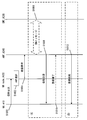
- FIG. 1 is a diagram schematically illustrating a mobile communication system.
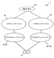
- FIG. 2 is a diagram illustrating an example of a configuration of an access network in a mobile communication system.
- FIG. 3 is a diagram illustrating an example of a configuration and the like of a core network_A in a mobile communication system.
- FIG. 3 is a diagram illustrating an example of a configuration and the like of a core network_B in a mobile communication system.
- FIG. 3 is a diagram illustrating a device configuration of a UE.
- FIG. 3 is a diagram illustrating a device configuration of eNB / NR @ node.
- FIG. 3 is a diagram illustrating a device configuration of an MME / AMF.
- FIG. 1 is a diagram schematically illustrating a mobile communication system.
- FIG. 2 is a diagram illustrating an example of a configuration of an access network in a mobile communication system.
- FIG. 3 is a diagram illustrating an example of a configuration and the like of
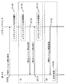
- FIG. 3 is a diagram showing a device configuration of SMF / PGW / UPF. It is a figure showing an initial procedure. It is a figure showing a registration procedure.
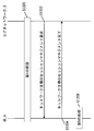
- FIG. 11 is a diagram showing a PDU session establishment procedure. It is a figure which shows the session management procedure led by the network.
- a mobile communication system 1 includes a terminal device (also referred to as a user device or a mobile terminal device) UE (User Equipment) _A10, an access network (AN; Access Network) _A, and an access network_B.
- UE User Equipment
- AN Access Network
- B Access network
- the combination of the access network _A and the core network _A90 may be referred to as EPS (Evolved Packet System; 4G mobile communication system), or the combination of the access network _B, the core network _B190, and the UE_A10 may be referred to as 5GS (5G System ; 5G mobile communication system), and the configurations of 5GS and EPS need not be limited to these.
- UE_A10 can be connected to a network service through 3GPP access (also referred to as 3GPP access or 3GPP access network) and / or non-3GPP access (also referred to as non-3GPP access or non-3GPP access network).
- Device may be used.
- UE_A10 may include a UICC (Universal Integrated Circuit Card) or an eUICC (Embedded UICC).
- UE_A10 may be a terminal device that can be wirelessly connected, or may be a mobile equipment (ME), a mobile station (MS), or a cellular Internet of Things (CIoT) terminal (CIoT UE).
- ME mobile equipment
- MS mobile station
- CIoT cellular Internet of Things
- UE_A10 can also be connected to an access network and / or a core network. Further, UE_A10 can be connected to DN_A and / or PDN_A via an access network and / or a core network. UE_A10 transmits and receives user data to and from DN_A and / or PDN_A using a PDU (Protocol Data Unit or Packet Data Unit) session and / or a PDN (Packet Data Network) connection (also referred to as a PDN connection). ). Furthermore, communication of user data is not limited to IP (Internet Protocol) communication (IPv4 or IPv6) .For example, EPS may be non-IP communication, or 5GS may be Ethernet (registered trademark) communication or Unstructured communication. There may be.
- IP Internet Protocol
- IPv4 or IPv6 IP (Internet Protocol) communication
- EPS may be non-IP communication
- 5GS may be Ethernet (registered trademark) communication or Unstructured communication. There may be.
- the PDU session is the connectivity established between UE_A10 and DN_A5 in order to provide a PDU connection service. More specifically, the PDU session may be a connectivity established between UE_A10 and a foreign gateway.
- the external gateway may be a UPF, a PGW (Packet Data Network Network), or the like.
- the PDU session may be a communication path established for transmitting and receiving user data between UE_A10 and the core network and / or the DN, or may be a communication path for transmitting and receiving PDUs.
- the PDU session may be a session established between the UE_A10 and the core network and / or the DN, and is configured by a logical path configured by one or more bearers or the like between devices in the mobile communication system 1. Communication channel may be used. More specifically, the PDU session may be a connection established between UE_A10 and core network_B190 and / or an external gateway, or a connection established between UE_A10 and UPF. Also, the PDU session may be the connectivity and / or connection between UE_A10 and UPF_A235 via NR node_A122. Further, the PDU session may be identified by a PDU session ID and / or an EPS bearer ID.
- UE_A10 can execute transmission and reception of user data with a device such as an application server arranged in DN_A5 using a PDU session.
- the PDU session can transfer user data transmitted and received between UE_A10 and a device such as an application server located in DN_A5.
- each device UE_A10, a device in the access network, and / or a device in the core network, and / or a device in the data network
- identification information include APN (Access Point Name), TFT (Traffic Flow Template), session type, application identification information, DN_A5 identification information, NSI (Network Slice Instance) identification information, and DCN (Dedicated Core Network). ) At least one of the identification information and the access network identification information may be included, and other information may be further included. Further, when a plurality of PDU sessions are established, each piece of identification information associated with the PDU session may have the same content or different content. Further, the NSI identification information is information for identifying the NSI, and may be NSI ID or Slice Instance ID.
- UTRAN Universal Terrestrial Radio Access Network
- E-UTRAN Evolved Universal Terrestrial Radio Access Network
- NG-RAN 5G- RAN
- UTRAN_A20 and / or E-UTRAN_A80 and / or NG-RAN_A120 are referred to as 3GPP access or 3GPP access network
- wireless LAN access network and non-3GPPGPAN are non-3GPP access or non-3GPP access network. It may be called.
- Each wireless access network includes a device (eg, a base station device or an access point) to which UE_A10 is actually connected.
- E-UTRAN_A80 is an LTE access network and includes one or more eNB_A45.
- eNB_A45 is a radio base station to which UE_A10 connects by E-UTRA (Evolved Universal Terrestrial Radio Access).
- E-UTRA Evolved Universal Terrestrial Radio Access
- each eNB may be connected to each other.
- NG-RAN_A120 is a 5G access network, which may be the (R) AN described in FIG. 4, including one or more NR nodes (New Radio Access Technology nodes) _A122 and / or ng-eNB. Be composed.
- NR @ node_A122 is a wireless base station to which UE_A10 is connected in 5G wireless access (5G @ Radio @ Access), and is also referred to as gNB.
- the ng-eNB may be an eNB (E-UTRA) constituting a 5G access network, and may be connected to the core network_B190 via the NR node_A or may be directly connected to the core network_B190. May be.
- E-UTRA eNB
- each NR ⁇ node_A122 and / or ng-eNB may be connected to each other.
- NG-RAN_A120 may be an access network configured with E-UTRA and / or 5G Radio Access.
- NG-RAN_A120 may include eNB_A45, NRnode_A122, or both.
- eNB_A45 and NR @ node_A122 may be the same device. Therefore, NR node_A122 can be replaced with eNB_A45.
- UTRAN_A20 is an access network of the 3G mobile communication system, and includes an RNC (Radio Network Controller) _A24 and an NB (Node) B) _A22.
- NB_A22 is a radio base station to which UE_A10 connects by UTRA (Universal @ Terrestrial @ Radio @ Access), and UTRAN_A20 may include one or more radio base stations.
- the RNC_A24 is a control unit that connects the core network_A90 and the NB_A22, and the UTRAN_A20 may include one or more RNCs. Also, the RNC_A24 may be connected to one or more NB_A22.
- UE_A10 being connected to each radio access network means being connected to a base station device, an access point, or the like included in each radio access network, and transmitting and receiving data and signals. Is also via a base station device or an access point.
- the control message transmitted and received between UE_A10 and core network_B190 may be the same control message regardless of the type of access network. Therefore, transmitting and receiving a message between the UE_A10 and the core network_B190 via the NRAnode_A122 may be the same as transmitting a message between the UE_A10 and the core network_B190 via the eNB_A45.
- the access network is a wireless network connected to UE_A10 and / or the core network.
- the access network may be a 3GPP access network or a non-3GPP access network.
- the 3GPP access network may be UTRAN_A20, E-UTRAN_A80, NG-RAN (Radio Access Network) _A120, and the non-3GPP access network may be a wireless LAN access point (WLAN AN).
- WLAN AN wireless LAN access point
- UE_A10 may connect to the access network to connect to the core network, or may connect to the core network via the access network.
- DNDN_A5 and PDN_A6 are data networks (Data @ Network) that provide communication services to UE_A10, and may be configured as a packet data service network or may be configured for each service. Further, DN_A5 may include a connected communication terminal. Therefore, connecting to DN_A5 may be connecting to a communication terminal or server device arranged in DN_A5. Further, transmitting / receiving user data to / from DN_A5 may be transmitting / receiving user data to / from a communication terminal or server device arranged in DN_A5. Although DN_A5 is outside the core network in FIG. 1, it may be inside the core network.
- the core network_A90 and / or the core network_B190 may be configured as devices in one or more core networks.
- the devices in the core network may be devices that execute some or all of the processing or functions of each device included in the core network_A90 and / or the core network_B190.
- a device in the core network may be referred to as a core network device.
- the core network refers to an IP mobile communication network operated by a mobile communication operator (MNO; Mobile Network Operator) connected to the access network and / or the DN.
- the core network may be a core network for a mobile communication company that operates and manages the mobile communication system 1, or a virtual mobile communication carrier such as MVNO (Mobile Virtual Network Operator), MVNE (Mobile Virtual Network Enabler), or a virtual mobile communication carrier. It may be a core network for a mobile communication service provider.
- the core network_A90 may be an EPC (Evolved @ Packet @ Core) constituting an EPS (Evolved @ Packet @ System), and the core network_B190 may be a 5GC (5G @ Core @ Network) constituting a 5GS.
- the core network_B190 may be a core network of a system that provides a 5G communication service.
- the EPC may be the core network_A90
- the 5GC may be the core network_B190.
- the core network_A90 and / or the core network_B190 are not limited to this, and may be networks for providing mobile communication services.
- the core network_A90 includes HSS (Home Subscriber Server) _A50, AAA (Authentication Authorization Accounting), PCRF (Policy and Charging Rules), PGW_A30, ePDG, SGW_A35, MME (Mobility Management Entity) _A40, SGSN (Serving GPRS Support Node) and SCEF may be included. These may be configured as an NF (Network Function). The NF may refer to a processing function configured in the network. Further, the core network_A90 can be connected to a plurality of radio access networks (UTRAN_A20, E-UTRAN_A80).
- HSS_A50 HSS
- PGW_A30 PGW
- SGW_A35 SGW
- MME_A40 MME
- DN_A5 and / or PDN_A6 is also called DN or PDN.
- PGW_A30 is a relay device that is connected to DN, SGW_A35, ePDG, WLAN ⁇ ANa70, PCRF, and AAA, and transfers user data as a gateway between DN (DN_A5 and / or PDN_A6) and core network_A90.
- the PGW_A30 may be a gateway for IP communication and / or non-IP communication.
- the PGW_A30 may have a function of transferring IP communication, or may have a function of converting non-IP communication and IP communication.
- a plurality of such gateways may be arranged in the core network_A90. Further, a plurality of arranged gateways may be gateways connecting the core network_A90 and a single DN.
- the U-Plane (User @ Plane; @UP) may be a communication path for transmitting and receiving user data, or may be configured by a plurality of bearers. Further, the C-Plane (Control @ Plane; $ CP) may be a communication path for transmitting and receiving a control message, or may be composed of a plurality of bearers.
- PGW_A30 may be connected to SGW and DN and UPF (User plane function) and / or SMF (Session Management function), or may be connected to UE_A10 via U-Plane. Further, PGW_A30 may be configured together with UPF_A235 and / or SMF_A230.
- the MME_A40 is a control device that is connected to the SGW_A35, the access network, the HSS_A50, and the SCEF, and performs location information management including mobility management of the UE_A10 via the access network and access control. Further, MME_A40 may include a function as a session management device that manages a session established by UE_A10. Further, a plurality of such control devices may be arranged in the core network_A90. For example, a location management device different from the MME_A40 may be configured. A location management device different from MME_A40 may be connected to SGW_A35, an access network, SCEF, and HSS_A50, similarly to MME_A40. Further, MME_A40 may be connected to AMF (Access / Mobility / Management / Function).
- AMF Access / Mobility / Management / Function
- the MMEs may be connected to each other. Thereby, transmission and reception of the context of UE_A10 may be performed between MMEs.
- the MME_A40 is a management device that transmits and receives the control information related to the mobility management and the session management to and from the UE_A10.
- the MME_A40 may be a management device configured in one or more core networks or DCNs or NSIs, or may include one or more core networks or It may be a management device connected to DCN or NSI.
- the plurality of DCNs or NSIs may be operated by a single communication carrier or may be operated by different communication carriers.
- MME_A40 may be a relay device that transfers user data as a gateway between core network_A90 and the access network.
- the user data transmitted and received by the MME_A40 as a gateway may be small data.
- MME_A40 may be an NF that plays a role of mobility management such as UE_A10, or may be an NF that manages one or a plurality of NSIs. MME_A40 may be an NF that plays one or more of these roles.
- the NF may be one or more devices arranged in the core network _A90, and a CP function for control information and / or a control message (hereinafter, CPF (Control Plane Function) or Control Plane Network Function). ) Or a shared CP function shared between a plurality of network slices.
- CPF Control Plane Function
- Control Plane Network Function Control Plane Network Function
- NF is a processing function configured in the network. That is, the NF may be a functional device such as an MME, an SGW, a PGW, a CPF, an AMF, an SMF, or an UPF, or a function or capability capability information such as an MM (Mobility Management) or an SM (Session Management). Further, the NF may be a functional device for realizing a single function or a functional device for realizing a plurality of functions. For example, the NF for realizing the MM function and the NF for realizing the SM function may exist separately, or the NF for realizing both the MM function and the SM function exists. You may.
- HSS_A50 is a management node that is connected to MME_A40, AAA, and SCEF and manages subscriber information.
- the subscriber information of HSS_A50 is referred to, for example, at the time of access control of MME_A40.
- HSS_A50 may be connected to a location management device different from MME_A40.
- HSS_A50 may be connected to CPF_A140.
- HSS_A50 and the UDM (Unified Data Management) _A245 may be configured as different devices and / or NFs, or may be configured as the same device and / or NF.
- AAA is connected to PGW30, HSS_A50, PCRF, and WLAN ANa70, and performs access control of UE_A10 connected via WLAN ANa70.
- PCRF is connected to PGW_A30, WLAN ANa75, AAA, DN_A5, and / or PDN_A6, and performs QoS management for data delivery. For example, it manages the QoS of the communication path between UE_A10 and DN_A5 and / or PDN_A6.
- the PCRF may be a device that creates and / or manages a PCC (Policy and Charging Control) rule and / or a routing rule used when each device transmits and receives user data.
- PCC Policy and Charging Control
- the PCRF may be a PCF that creates and / or manages policies. More specifically, the PCRF may be connected to UPF_A235.
- the ePDG is connected to the PGW 30 and the WLAN ANb75, and performs delivery of user data as a gateway between the core network_A90 and the WLAN ANb75.
- the SGSN is connected to UTRAN_A20, GERAN and SGW_A35, and is a control device for location management between the 3G / 2G access network (UTRAN / GERAN) and the LTE (4G) access network (E-UTRAN). It is. Further, the SGSN has a function of selecting the PGW and the SGW, a function of managing the time zone of the UE_A10, and a function of selecting the MME_A40 at the time of handover to the E-UTRAN.
- the SCEF is a relay device that is connected to DN_A5 and / or PDN_A6, MME_A40, and HSS_A50, and transfers user data as a gateway that connects DN_A5 and / or PDN_A6 and core network_A90.
- SCEF may be a gateway for non-IP communication.
- SCEF may have a function of converting non-IP communication and IP communication.
- a plurality of such gateways may be arranged in the core network_A90.
- a plurality of gateways for connecting the core network_A90 with a single DN_A5 and / or PDN_A6 and / or DN may be provided.
- the SCEF may be configured outside the core network or may be configured inside the core network.
- the core network_B190 includes AUSF (Authentication Server Function), AMF (Access and Mobility Management Function) _A240, UDSF (Unstructured Data Storage Function), NEF (Network Exposure Function), NRF (Network Repository Function), PCF (Policy Control Function), SMF (Session Management Function) _A230, UDM (Unified Data Management), UPF (User Plane Function) _A235, AF (Application Function), N3IWF (Non-3GPP InterWorking Function), at least one of them may be included. . These may be configured as an NF (Network Function). The NF may refer to a processing function configured in the network.
- AMF_A240 AMF
- SMF_A230 SMF
- UPF_A235 UPF
- DN_A5 DN
- FIG. 4 also shows an N1 interface (hereinafter also referred to as a reference point), an N2 interface, an N3 interface, an N4 interface, an N6 interface, an N9 interface, and an N11 interface.
- the N1 interface is an interface between the UE and the AMF
- the N2 interface is an interface between the (R) AN (access network) and the AMF
- the N3 interface is a (R) AN (access network).
- the interface between UPF, the N4 interface is the interface between SMF and UPF, the N6 interface is the interface between UPF and DN, and the N9 interface is the interface between UPF and UPF.
- N11 interface is the interface between AMF and SMF. Using these interfaces, communication can be performed between the devices.
- (R) AN is also referred to as NG RAN hereinafter.
- AMF_A240 is connected to other AMF, SMF (SMF_A230), access network (that is, UTRAN_A20, E-UTRAN_A80, and NG-RAN_A120), UDM, AUSF, and PCF.
- SMF SMF
- AMF_A240 is registration management (Registration management), connection management (Connection management), reachability management (Reachability management), mobility management (Mobility management) such as UE_A10, transfer of SM (Session Management) message between UE and SMF , Access authentication (Access Authentication, Access Authorization), security anchor function (SEA; Security Anchor Function), security context management (SCM; Security Context Management), support of N2 interface for N3IWF, NAS signal with UE via N3IWF It may have a role of supporting transmission / reception, authentication of a UE connected via the N3IWF, management of an RM state (Registration Management State), management of a CM state (Connection Management State), and the like.
- SM Session Management
- SEA Security Anchor Function
- SCM Security Context Management
- AMF_A240s may be arranged in the core network_B190.
- AMF_A240 may be an NF that manages one or more NSIs (Network ⁇ Slice ⁇ Instances).
- the AMF_A240 may be a shared CP function (CCNF; Control Plane Network Function) shared by a plurality of NSIs.
- CCNF Control Plane Network Function
- the RM state includes a non-registered state (RM-DEREGISTERED @ state) and a registered state (RM-REGISTERED @ state).
- RM-DEREGISTERED since the UE is not registered in the network, the AMF cannot reach the UE because the UE context in the AMF does not have information on the location or routing that is valid for the UE. is there.
- the UE in the RM-REGISTERED state, since the UE is registered in the network, the UE can receive a service that requires registration with the network.
- CMThe CM state includes a non-connection state (CM-IDLE @ state) and a connection state (CM-CONNECTED @ state).
- CM-IDLE non-connection state
- CM-CONNECTED connection state
- the UE In the CM-IDLE state, the UE is in the RM-REGISTERED state but does not have a NAS signaling connection established with the AMF via the N1 interface.
- the UE does not have the connection of the N2 interface (N2Nconnection) and the connection of the N3 interface (N3 connection).
- N2Nconnection the connection of the N3 interface
- N3 connection connection of the N3 interface
- the NAS signaling connection NAS signaling connection
- the UE may have a connection of the N2 interface (N2) connection) and / or a connection of the N3 interface (N3 connection).
- SMF_A230 has a session management (Session Management; SM) function such as a PDU session, an IP address allocation (IP address) for UE and its management function, a UPF selection and control function, and a traffic to an appropriate destination.
- SM Session Management
- Each session may have a function of providing SM information, a function of determining an SSC mode (Session ⁇ Service ⁇ Continuity ⁇ mode) for a session, a roaming function, and the like.
- the SMF_A230 may be connected to the AMF_A240, the UPF_A235, the UDM, and the PCF.
- UPUPF_A235 is also connected to DN_A5, SMF_A230, other UPFs, and access networks (that is, UTRAN_A20, E-UTRAN_A80, and NG-RAN_A120).
- UPF_A235 is an anchor for intra-RAT mobility or inter-RAT mobility, packet routing and forwarding (Packet routing & forwarding), UL CL (Uplink Classifier) function that supports routing of multiple traffic flows to one DN, Branching point function that supports multi-homed PDU session (multi-homed PDU session), QoS processing for user plane, verification of uplink traffic (verification), buffering of downlink packet, downlink data notification (Downlink Data Notification) It may have a role such as a trigger function.
- Packet routing & forwarding Packet routing & forwarding
- UL CL Uplink Classifier
- branching point function that supports multi-homed PDU session (multi-homed PDU session)
- QoS processing for user plane verification of uplink traffic (verification
- the UPF_A235 may be a relay device that transfers user data as a gateway between the DN_A5 and the core network_B190.
- the UPF_A235 may be a gateway for IP communication and / or non-IP communication.
- the UPF_A235 may have a function of transferring IP communication, and may have a function of converting non-IP communication and IP communication.
- a plurality of arranged gateways may be gateways connecting the core network_B190 and a single DN.
- the UPF_A235 may have connectivity with another NF, or may be connected to each device via another NF.
- a UPF_C239 (also referred to as a branching point or an uplink classifier), which is a UPF different from the UPF_A235, may exist as a device or an NF. If UPF_C239 is present, a PDU session between UE_A10 and DN_A5 will be established via the access network, UPF_C239, UPF_A235.
- AUAUSF is connected to UDM and AMF_A240. AUSF functions as an authentication server.
- UDSF provides a function for all NFs to store and retrieve information as unstructured data.
- NEF will provide a means to securely provide services and capabilities provided by the 3GPP network.
- Information received from other NFs is stored as structured data (structured data).
- the NRF Upon receiving an NF discovery request (NF ⁇ Discovery Request) from the NF instance, the NRF provides the NF with information on the discovered NF instance, and information on available NF instances and services supported by the instance. Or hold.
- NF ⁇ Discovery Request NF ⁇ Discovery Request
- PCF is connected to SMF (SMF_A230), AF, and AMF_A240. Provides policy rules (policy rule), etc.
- UDM is connected to AMF_A240, SMF (SMF_A230), AUSF, and PCF.
- UDM includes UDM FE (application front end) and UDR (User Data Repository).
- the UDM FE performs processes such as authentication information (credentials), location management (location @ management), and subscriber management (subscription @ management).
- the UDR stores the data required by the UDM ⁇ FE and the policy profiles required by the PCF.
- AF is connected to PCF. AF affects traffic routing and is involved in policy control.
- the N3IWF establishes an IPsec tunnel with the UE, relays NAS (N1) signaling between the UE and the AMF, processes N2 signaling sent from the SMF and relayed by the AMF, and establishes IPsec Security Association (IPsec SA) , Provides functions such as relaying user-plane packets between the UE and the UPF, and selecting AMF.
- IPsec SA IPsec Security Association
- each device may operate on physical hardware, or may be logical hardware virtually configured on general-purpose hardware. It may operate on hardware.
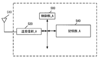
- UE_A10 includes a control unit_A500, a transmission / reception unit_A520, and a storage unit_A540.
- the transmission / reception unit_A520 and the storage unit_A540 are connected to the control unit_A500 via a bus.
- an external antenna 410 is connected to the transmission / reception unit_A520.
- the control unit_A500 is a functional unit for controlling the entire UE_A10, and realizes various processes of the entire UE_A10 by reading and executing various information and programs stored in the storage unit_A540.
- the transmitting / receiving unit _A520 is a functional unit for UE_A10 to connect to a base station (UTRAN_A20, E-UTRAN_A80, and NG-RAN_A120) and / or a wireless LAN access point (WLAN AN) in the access network and to connect to the access network. is there.
- UE_A10 can connect to a base station and / or an access point in an access network via external antenna 410 connected to transmitting / receiving section_A520.
- UE_A10 transmits / receives user data and / or control information to / from a base station and / or an access point in an access network via an external antenna 410 connected to the transmission / reception unit_A520. Can be.
- the storage unit_A540 is a functional unit that stores programs, data, and the like necessary for each operation of the UE_A10, and includes, for example, a semiconductor memory, an HDD (Hard Disk Drive), an SSD (Solid State Drive), and the like.
- the storage unit_A540 stores identification information, control information, flags, parameters, rules, policies, and the like included in a control message transmitted and received in a communication procedure described below.
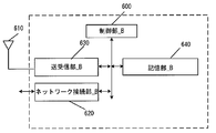
- the eNB_A45 and the NR node_A122 include a control unit_B600, a network connection unit_B620, a transmission / reception unit_B630, and a storage unit_B640.
- the network connection unit_B620, the transmission / reception unit_B630, and the storage unit_B640 are connected to the control unit_B600 via a bus.
- an external antenna 510 is connected to the transmitting / receiving section_B630.
- the control unit_B600 is a functional unit for controlling the entire eNB_A45 and NR node_A122, and reads out and executes various information and programs stored in the storage unit_B640, thereby controlling the entire eNB_A45 and NR node_A122. Implement various processes.
- Transmitting / receiving section_B630 is a functional section for connecting eNB_A45 and NR node_A122 to UE_A10.
- the eNB_A45 and the NR node_A122 can transmit / receive user data and / or control information to / from the UE_A10 via the transmission / reception unit_B630.
- Storage unit_B640 is a functional unit that stores programs, data, and the like necessary for each operation of eNB_A45 and NR node_A122.
- the storage unit_B640 includes, for example, a semiconductor memory, an HDD, an SSD, and the like.
- the storage unit_B640 stores identification information, control information, flags, parameters, and the like included in a control message transmitted and received in a communication procedure described later.
- the storage unit_B640 may store such information as a context for each UE_A10.
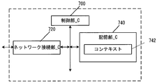
- the MME_A40 or the AMF_A240 includes a control unit_C700, a network connection unit_C720, and a storage unit_C740.
- the network connection unit_C720 and the storage unit_C740 are connected to the control unit_C700 via a bus.
- the storage unit_C740 stores a context 642.
- the control unit_C700 is a functional unit for controlling the entire MME_A40 or AMF_A240, and realizes various processes of the entire AMF_A240 by reading and executing various information and programs stored in the storage unit_C740. I do.
- Network connection unit_C720 MME_A40 or AMF_A240, other MME_A40, AMF_240, SMF_A230, base station in the access network (UTRAN_A20 and E-UTRAN_A80 and NG-RAN_A120) and / or wireless LAN access point (WLAN AN), UDM , AUSF, PCF.
- MME_A40 or AMF_A240 transmits / receives user data and / or control information to / from a base station and / or access point in the access network, UDM, AUSF, and PCF via the network connection unit_C720. Can be.
- Storage unit_C740 is a functional unit that stores programs, data, and the like necessary for each operation of MME_A40 or AMF_A240.
- the storage unit_C740 includes, for example, a semiconductor memory, an HDD, an SSD, and the like.
- the storage unit_C740 stores identification information, control information, flags, parameters, and the like included in a control message transmitted and received in a communication procedure described later.
- the context 642 stored in the storage unit_C740 may include a context stored for each UE, a context stored for each PDU session, and a context stored for each bearer.
- the context stored for each PDU session may include APN in Use, Assigned Session Type, IP Address (es), PGW F-TEID, SCEF ID, and Default bearer.
- the context stored for each bearer includes EPS Bearer ID, TI, TFT, SGW F-TEID, PGW F-TEID, MME F-TEID, eNB Address, NR node Address, WAG Address, eNB ID, NR node ID and WAGID may be included.
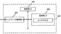
- the SMF_A230 includes a control unit_D800, a network connection unit_D820, and a storage unit_D840.
- the network connection unit_D820 and the storage unit_D840 are connected to the control unit_D800 via a bus. Further, the storage unit_D840 stores a context 742.
- the control unit_D800 of the SMF_A230 is a functional unit for controlling the entire SMF_A230, and realizes various processes of the entire SMF_A230 by reading out and executing various information and programs stored in the storage unit_D840. I do.
- the network connection unit_D820 of the SMF_A230 is a functional unit for the SMF_A230 to connect to the AMF_A240, UPF_A235, UDM, and PCF.
- the SMF_A230 can transmit / receive user data and / or control information to / from the AMF_A240, UPF_A235, UDM, PCF via the network connection unit_D820.
- the storage unit_D840 of the SMF_A230 ⁇ is a functional unit that stores programs, data, and the like necessary for each operation of the SMF_A230.
- the storage unit_D840 of the SMF_A230 includes, for example, a semiconductor memory, an HDD, an SSD, and the like.
- the storage unit_D840 of the SMF_A230 stores identification information, control information, flags, parameters, and the like included in control messages transmitted and received in a communication procedure described later.
- the context 742 stored in the storage unit _D840 of the SMF_A230 a context stored for each UE, a context stored for each APN, a context stored for each PDU session, and stored for each bearer There may be contexts.
- the context stored for each UE may include IMSI, ME Identity, MSISDN, RAT type.
- the context stored for each APN may include APN ⁇ in ⁇ use.
- the context stored for each APN may be stored for each Data ⁇ Network ⁇ Identifier.
- the context stored for each PDU session may include Assigned Session Type, IP Address (es), SGW F-TEID, PGWF-TEID, and Default Bearer.
- the context stored for each bearer may include EPS Bearer ID, TFT, SGW F-TEID, and PGW F-TEID.
- FIG. 8 shows a device configuration example of the PGW_A30 or the UPF_A235.
- PGW_A30 or UPF_A235 includes a control unit_D800, a network connection unit_D820, and a storage unit_D840, respectively.
- the network connection unit_D820 and the storage unit_D840 are connected to the control unit_D800 via a bus. Further, the storage unit_D840 stores a context 742.
- the control unit _D800 of the PGW_A30 or the UPF_A235 is a functional unit for controlling the entire PGW_A30 or the UPF_A235, and reads and executes various information and programs stored in the storage unit _D840 to execute the PGW_A30 or the UPF_A235. Implement the entire process.
- the network connection unit D820 of the PGW_A30 or the UPF_A235 is such that the PGW_A30 or the UPF_A235 is connected to the DN (that is, DN_A5), the SMF_A230, another UPF_A235, and the access network (that is, UTRAN_A20, E-UTRAN_A80, and NG-RAN_A120). It is a functional part for performing.
- UPF_A235 via the network connection _D820, DN (that is, DN_A5), SMF_A230, other UPF_A235, and access network (that is, UTRAN_A20 and E-UTRAN_A80 and NG-RAN_A120), User data and / or control information can be sent and received.
- DN that is, DN_A5
- SMF_A230 other UPF_A235
- access network that is, UTRAN_A20 and E-UTRAN_A80 and NG-RAN_A120
- the storage unit_D840 of the UPF_A235 is a functional unit that stores programs, data, and the like necessary for each operation of the UPF_A235.
- the storage unit_D840 of the UPF_A235 includes, for example, a semiconductor memory, an HDD, an SSD, and the like.
- the storage unit_D840 of the UPF_A235 stores identification information, control information, flags, parameters, and the like included in control messages transmitted and received in a communication procedure described later.
- a context stored for each UE a context stored for each APN, a context stored for each PDU session, and stored for each bearer There may be contexts.
- the context stored for each UE may include IMSI, ME Identity, MSISDN, RAT type.
- the context stored for each APN may include APN ⁇ in ⁇ use.
- the context stored for each APN may be stored for each Data ⁇ Network ⁇ Identifier.
- the context stored for each PDU session may include Assigned Session Type, IP Address (es), SGW F-TEID, PGWF-TEID, and Default Bearer.
- the context stored for each bearer may include EPS Bearer ID, TFT, SGW F-TEID, and PGW F-TEID.
- IMSI International Mobile Subscriber Identity
- MME_A40 / CPF_A140 / AMF_A2400, and SGW_A35 may be equal to the IMSI stored by HSS_A50.
- EMM State / MM State indicates a mobility management state of UE_A10 or MME_A40 / CPF_A140 / AMF_A240.
- EMM @ State / MM @ State may be an EMM-REGISTERED state where UE_A10 is registered in the network (registered state) and / or an EMM-DEREGISTERD state where UE_A10 is not registered in the network (unregistered state).
- the EMM @ State / MM @ State may be an ECM-CONNECTED state in which the connection between the UE_A10 and the core network is maintained, and / or an ECM-IDLE state in which the connection is released.
- EMM @ State / MM @ State may be information that can distinguish between a state in which UE_A10 is registered in the EPC and a state in which UE_A10 is registered in NGC or 5GC.
- GUTI Globally Unique Temporary Identity
- MME_A40 / CPF_A140 / AMF_A240 identification information GUMMEI (Globally Unique MME Identifier)
- M-TMSI M-Temporary Mobile Subscriber Identity
- ME @ Identity is the ID of UE_A10 or ME, and may be, for example, IMEI (International Mobile Equipment Identity) or IMEISV (IMEI Software Version).
- MSISDN represents the basic telephone number of UE_A10.
- MSISDN stored in MME_A40 / CPF_A140 / AMF_A240 may be the information indicated by the storage unit of HSS_A50.
- GUTI may include information for identifying CPF_140.
- ⁇ MME ⁇ F-TEID is information for identifying MME_A40 / CPF_A140 / AMF_A240.
- the MME F-TEID may include the IP address of MME_A40 / CPF_A140 / AMF_A240, or may include the TEID (Tunnel / Endpoint Identifier) of MME_A40 / CPF_A140 / AMF_A240, or may include both of them. Is also good.
- the IP address of MME_A40 / CPF_A140 / AMF_A240 and the TEID of MME_A40 / CPF_A140 / AMF_A240 may be stored independently.
- the MME @ F-TEID may be identification information for user data or identification information for control information.
- ⁇ SGW ⁇ F-TEID is information for identifying SGW_A35.
- the SGW F-TEID may include the IP address of the SGW_A35, may include the TEID of the SGW_A35, or may include both of them. Further, the IP address of SGW_A35 and the TEID of SGW_A35 may be stored independently. Further, the SGW @ F-TEID may be identification information for user data or identification information for control information.
- ⁇ PGW ⁇ F-TEID is information for identifying PGW_A30 / UPGW_A130 / SMF_A230 / UPF_A235.
- the PGW F-TEID may include the IP address of PGW_A30 / UPGW_A130 / SMF_A230 / UPF_A235, or may include the TEID of PGW_A30 / UPGW_A130 / SMF_A230 / UPF_A235, or may include both of these. Good.
- IP address of PGW_A30 / UPGW_A130 / SMF_A230 / UPF_A235 and the TEID of PGW_A30 / UPGW_A130 / SMF_A230 / UPF_A235 may be stored independently.
- PGW @ F-TEID may be identification information for user data or identification information for control information.
- ⁇ ENB ⁇ F-TEID is information for identifying eNB_A45.
- the eNB F-TEID may include the IP address of eNB_A45, may include the TEID of eNB_A45, or may include both of them. Further, the IP address of eNB_A45 and the TEID of SGW_A35 may be stored independently. Further, eNB @ F-TEID may be identification information for user data or identification information for control information.
- APN may be identification information for identifying a core network and an external network such as a DN. Further, the APN can be used as information for selecting a gateway such as PGW_A30 / UPGW_A130 / UPF_A235 that connects the core network_A90.
- the APN may be a DNN (Data ⁇ Network ⁇ Name). Therefore, APN may be expressed as DNN, and DNN may be expressed as APN.
- the APN may be identification information for identifying such a gateway, or identification information for identifying an external network such as a DN.
- identification information for identifying such a gateway or identification information for identifying an external network such as a DN.
- ⁇ UE ⁇ Radio ⁇ Access ⁇ Capability is identification information indicating the radio access capability of UE_A10.
- UE Network Capability includes security algorithms and key derivation functions supported by UE_A10.
- MS Network Capability is information that includes one or more pieces of information necessary for SGSN_A42 for UE_A10 having a GERAN_A25 and / or UTRAN_A20 function.
- Access @ Restriction is registration information of access restriction.
- eNB @ Address is the IP address of eNB_A45.
- MME UE S1AP ID is information for identifying UE_A10 in MME_A40 / CPF_A140 / AMF_A240.
- eNB ⁇ UE ⁇ S1AP ⁇ ID is information for identifying UE_A10 in eNB_A45.
- APN in Use is the recently used APN.
- APN ⁇ in ⁇ Use may be Data ⁇ Network ⁇ Identifier. This APN may be composed of network identification information and default operator identification information. Further, APN @ in @ Use may be information for identifying the DN at which the PDU session is established.
- Type is information indicating the type of the PDU session.
- Assigned Session Type may be Assigned PDN Type.
- the type of the PDU session may be IP or non-IP.
- IP it may further include information indicating the type of PDN allocated from the network.
- the Assigned Session Type may be IPv4, IPv6, or IPv4v6.
- IP @ Address is the IP address assigned to the UE.
- the IP address may be an IPv4 address, an IPv6 address, an IPv6 prefix, or an interface ID.
- Assigned Session Type indicates non-IP, the element of IP Address may not be included.
- ⁇ DN ⁇ ID is identification information for identifying the core network_B190 and an external network such as a DN. Furthermore, the DN @ ID can also be used as information for selecting a gateway such as UPGW_A130 or PF_A235 that connects the core network_B190.
- the DN ID may be identification information for identifying such a gateway or identification information for identifying an external network such as a DN.
- the DN ID may be identification information for identifying such a gateway or identification information for identifying an external network such as a DN.
- the DN / ID may be a plurality of gateways that can be selected by the DN / ID.
- one gateway may be selected from among the plurality of gateways by another method using identification information other than the DN @ ID.
- the DN ⁇ ID may be information equal to the APN or information different from the APN. If the DN ID and the APN are different information, each device may manage information indicating the correspondence between the DN ID and the APN, or may perform a procedure for inquiring the APN using the DN ID. Alternatively, a procedure for inquiring the DN @ ID using the APN may be performed.
- ⁇ SCEF ⁇ ID is the IP address of SCEF_A46 used in the PDU session.
- Default @ Bearer is information acquired and / or generated when a PDU session is established, and is EPS bearer identification information for identifying a default bearer (default @ bearer) associated with the PDU session.
- EPS Bearer ID is identification information of the EPS bearer.
- EPS Bearer ID may be identification information for identifying SRB (Signaling Radio Bearer) and / or CRB (Control-plane Radio bearer) or identification information for identifying DRB (Data Radio Bearer).
- TI Transaction @ Identifier
- the EPS @ Bearer @ ID may be EPS bearer identification information for identifying a dedicated bearer. Therefore, identification information for identifying an EPS bearer different from the default bearer may be used.
- TFT indicates all packet filters associated with the EPS bearer.
- the TFT is information for identifying a part of user data to be transmitted and received, and the UE_A10 transmits and receives the user data identified by the TFT using an EPS bearer associated with the TFT.
- UE_A10 transmits / receives the user data identified by the TFT using an RB (Radio Bearer) associated with the TFT.
- the TFT may associate user data such as application data to be transmitted and received with an appropriate transfer path, or may be identification information for identifying application data.
- UE_A10 may transmit and receive user data that cannot be identified by TFT using a default bearer.
- UE_A10 may store in advance a TFT associated with the default bearer.
- ⁇ Default ⁇ Bearer is EPS bearer identification information for identifying the default bearer associated with the PDU session.
- the EPS bearer may be a logical communication path established between UE_A10 and PGW_A30 / UPGW_A130 / UPF_A235, or a communication path configuring a PDN connection / PDU session.
- the EPS bearer may be a default bearer or a dedicated bearer.
- the EPS bearer may be configured to include an RB established between UE_A10 and a base station and / or an access point in the access network. Further, the RB and the EPS bearer may be associated one-to-one.
- the identification information of the RB may be associated one-to-one with the identification information of the EPS bearer, or may be the same identification information.
- RB may be SRB and / or CRB, or DRB.
- Default @ Bearer may be information that UE_A10 and / or SGW_A35 and / or PGW_A30 / UPGW_A130 / SMF_A230 / UPF_A235 acquire from the core network when a PDU session is established.
- the default bearer is an EPS bearer that is first established during a PDN connection / PDU session, and is an EPS bearer that can be established only once during one PDN connection / PDU session.
- the default bearer may be an EPS bearer that can be used for communication of user data that is not associated with a TFT.
- a dedicated bearer is an EPS bearer established after a default bearer is established in a PDN connection / PDU session, and is an EPS bearer that can be established multiple times in one PDN connection / PDU session. is there.
- the dedicated bearer is an EPS bearer that can be used for communication of user data associated with the TFT.
- ⁇ User ⁇ Identity is information for identifying a subscriber.
- User @ Identity may be IMSI or MSISDN. Further, User @ Identity may be identification information other than IMSI and MSISDN.
- Serving ⁇ Node ⁇ Information is information for identifying MME_A40 / CPF_A140 / AMF_A240 used in the PDU session, and may be the IP address of MME_A40 / CPF_A140 / AMF_A240.
- ⁇ ENB ⁇ Address is the IP address of eNB_A45.
- eNB ID is information for identifying the UE in eNB_A45.
- MME @ Address is the IP address of MME_A40 / CPF_A140 / AMF_A240.
- MME ID is information for identifying MME_A40 / CPF_A140 / AMF_A240.
- NR @ node @ Address is the IP address of NR @ node_A122.
- the NR @ node @ ID is information for identifying the NR @ node_A 122.
- WAG @ Address is the IP address of the WAG.
- WAG ID is information for identifying a WAG.
- Anchor or anchor point is a UFP that has a gateway function for DN and PDU sessions.
- the UPF serving as an anchor point may be a PDU session anchor, or may be an anchor.
- the SSC mode indicates a service session continuity (Session5Service Continuity) mode supported by the system and / or each device in the 5GC. More specifically, the mode may indicate the type of service session continuation supported by the PDU session established between UE_A10 and the anchor point).
- the anchor point may be the UPGW or UPF_A235.
- the SSC @ mode may be a mode indicating the type of service session continuation set for each PDU session.
- SSC @ mode may be composed of three modes, SSC @ mode @ 1, SSC @ mode @ 2, and SSC @ mode # 3. SSC @ mode is associated with the anchor point and cannot be changed while the PDU session is established.
- SSC mode 1 in the present embodiment is a mode of service session continuation in which the same UPF is maintained as an anchor point regardless of an access technology such as a RAT (Radio Access Technology) or a cell used when UE_A10 connects to a network. It is. More specifically, SSC ⁇ mode ⁇ 1 may be a mode for realizing the service session continuation without changing the anchor point used by the established PDU session even when the mobility of UE_A10 occurs.
- RAT Radio Access Technology
- SSC mode 2 in the present embodiment includes an anchor point associated with one SSC mode 2 in the PDU session
- the service session continuation that releases the PDU session first and subsequently establishes the PDU session is continued.
- SSC @ mode2 is a mode in which when a relocation of an anchor point occurs, a PDU session is deleted once and a new PDU session is established.
- ⁇ SSC ⁇ mode # 2 is a service session continuation mode in which the same UPF is maintained as an anchor point only in the UPF serving area. More specifically, SSC @ mode2 may be a mode for realizing service session continuation without changing the UPF used by the established PDU session as long as UE_A10 is in the serving area of the UPF. Further, SSC mode 2, such as exiting from the serving area of the UPF, when the mobility of UE_A10 occurs, change the UPF used by the established PDU session, even in the mode to realize the service session continuation Good.
- SSC mode 3 in the present embodiment is a service session continuation mode in which a PDU session can be established between a new anchor point and a UE for the same DN without releasing a PDU session between the UE and the anchor point. is there.
- SSC mode 3 is a PDU session established between UE_A10 and UPF, and / or before disconnecting the communication path, for the same DN, a new PDU session via a new UPF, and / or Alternatively, a service session continuation mode in which a communication path is permitted to be established. Further, SSC @ mode # 3 may be a service session continuation mode in which UE_A10 is allowed to enter multihoming.
- / or SSC mode 3 may be a mode in which service session continuation using a plurality of PDU sessions and / or UPFs associated with the PDU sessions is permitted.
- each device may realize service session continuation using a plurality of PDU sessions, or may realize service session continuation using a plurality of TUPFs.
- the selection of a new UPF may be performed by the network, and the new UPF may be a location where UE_A10 is connected to the network. May be the most suitable UPF. Further, when multiple PDU sessions and / or UPFs used by the PDU sessions are valid, UE_A10 immediately performs correspondence between application and / or flow communication with the newly established PDU session. Or may be performed based on the completion of communication.
- the network refers to at least a part of access network_A20 / 80, access network_B80 / 120, core network_A90, core network_B190, DN_A5, and PDN_A6. Further, at least one device included in at least a part of the access network _A20 / 80, the access network _B80 / 120, the core network _A90, the core network _B190, the DN_A5, and the PDN_A6 is referred to as a network or a network device. It may be called. That is, the fact that the network transmits and receives messages and / or performs procedures means that devices in the network (network devices) transmit and / or receive messages and / or perform procedures.
- a session management (SM; Session Management) message (NAS (Non-Access-Stratum) SM message or SM message) is a procedure for SM (session management procedure or SM procedure) May be a control message transmitted and received between UE_A10 and SMF_A230 via AMF_A240.
- the SM message includes a PDU session establishment request message, a PDU session establishment acceptance message, a PDU session completion message, a PDU session rejection message, a PDU session change request message, a PDU session change acceptance message, a PDU session change rejection message, and the like. You may.
- the procedure for the SM may include a PDU session establishment procedure, a PDU session change procedure, and the like.
- the TA list (TA ⁇ ⁇ list) is a list including one or more TAs assigned to UE_A10 by the network.
- UE_A10 may be able to move without executing the registration procedure while moving within one or more TAs included in the TA list.
- the TA list may be a group of information indicating an area where the UE_A10 can move without executing the registration procedure.
- a network slice (Network @ Slice) is a logical network that provides specific network capabilities and network characteristics.
- the network slice is also referred to as an NW slice.
- NSI Network @ Slice @ Instance
- the NSI in the present embodiment is an entity of a network slice (Network @ Slice) configured in the core network_B190 or one or more.
- the NSI in the present embodiment may be configured by a virtual NF (Network Function) generated using NST (Network Slice Template).
- NST Network Slice Template
- the NST is associated with a resource request for providing a required communication service or capability, and is a logical expression of one or a plurality of Network Function (NF).
- NF Network Function
- the NSI may be an aggregate in the core network_B190 configured by a plurality of NFs.
- the NSI may be a logical network configured to separate user data delivered by a service or the like. At least one NF may be configured in the network slice.
- the NF configured in the network slice may or may not be a device shared with another network slice.
- UE_A10, and / or devices in the network may include NSSAI and / or S-NSSAI and / or UE usage type and / or one or more network slice type IDs and / or one or more NS IDs.
- One or more network slices can be assigned based on registration information and / or APN.
- the S-NSSAI in the present embodiment is an abbreviation of Single ⁇ Network ⁇ Slice ⁇ Selection ⁇ Assistance ⁇ information and is information for identifying a network slice.
- the S-NSSAI may be composed of SST (Slice / Service type) and SD (Slice Differentiator).
- the S-NSSAI may include only the SST, or may include both the SST and the SD.
- the SST is information indicating the operation of the network slice expected in terms of functions and services.
- the SD may be information that complements the SST when one NSI is selected from a plurality of NSIs indicated by the SST.
- the S-NSSAI may be information specific to each PLMN (Public Land Mobile Network), standard information shared between PLMNs, or information specific to a carrier that differs for each PLMN. There may be.
- the SST and / or SD may be standard information (Standard Value) shared between PLMNs, or may be information (Non Standard Value) that is different for each PLMN and is specific to a communication carrier. May be.
- the network may store one or more S-NSSAIs in the registration information of UE_A10 as a default S-NSSAI.
- NSSAI Single Network Slice Selection Assistance information
- UE_A10 may store NSSAI permitted from the network for each PLMN.
- NSSAI may be information used to select AMF_A240.
- the operator A network in the present embodiment is a network operated by the network operator A (operator A).
- the operator A may develop a common NW slice with an operator B described later.
- the operator B network in the present embodiment is a network operated by the network operator B (operator B).
- the operator B may develop a common NW slice with the operator A.
- the first NW slice in the present embodiment is an NW slice to which an established PDU session belongs when the UE connects to a specific DN.
- the first NW slice may be an NW slice managed in the operator A network, or may be an NW slice commonly managed in the operator B network.
- the second NW slice in the present embodiment is an NW slice to which another PDU session that can be connected to the DN to which the PDU session belonging to the first NW slice is connected.
- the first NW slice and the second NW slice may be operated by the same operator or may be operated by different operators.
- Equivalent PLMN in the present embodiment is a PLMN that is treated as if it were the same PLMN as an arbitrary PLMN in the network.
- the DCN (Dedicated Core Network) in the present embodiment is a core network dedicated to a specific subscriber type and configured in the core network_A90.
- a DCN for a UE registered as a user of a Machine to Machine (M2M) communication function may be configured in the core network_A90.
- M2M Machine to Machine
- a default DCN for a UE without an appropriate DCN may be configured in the core network_A90.
- at least one or more MME_40 or SGSN_A42 may be arranged in the DCN, and at least one or more SGW_A35 or PGW_A30 or PCRF_A60 may be arranged.
- a DCN may be identified by a DCN ID, and a UE may be assigned to one DCN based on information such as a UE usage type and / or a DCN ID.
- the first timer in the present embodiment is a timer that manages the start of a procedure for session management such as a PDU session establishment procedure, and / or the transmission of an SM (Session Management) message such as a PDU session establishment request message, Information indicating the value of a back-off timer for managing the behavior of session management may be used.
- SM Session Management
- the first timer and / or the back-off timer may be referred to as a timer.
- each device may be prohibited from starting a procedure for session management and / or transmitting / receiving an SM message.
- the first timer may be set in association with at least one of the congestion management unit applied by the network and / or the congestion management unit identified by the UE.
- the SM message may be a NAS message used in a procedure for session management, and may be a control message transmitted and received between UE_A10 and SMF_A230 via AMF_A240. Further, the SM message includes a PDU session establishment request message, a PDU session establishment acceptance message, a PDU session completion message, a PDU session rejection message, a PDU session change request message, a PDU session change acceptance message, a PDU session change rejection message, and the like. You may. Further, the procedure for session management may include a PDU session establishment procedure, a PDU session change procedure, and the like. In these procedures, a back-off timer value may be included for each message received by UE_A10.
- the UE may set a back-off timer received from the NW as a first timer, may set a timer value by another method, or may set a random value. Also, when the back-off timer received from the NW is configured with a plurality, the UE may manage a plurality of "first timers" according to the plurality of back-off timers, or the UE holds Based on a policy, one timer value may be selected from a plurality of backoff timer values received from the NW, set as the first timer, and managed.
- the UE when receiving two back-off timer values, the UE sets the back-off timer values received from the NW to ⁇ first timer # 1 '' and ⁇ first timer # 2 '', respectively, and manages them. I do. Further, one value may be selected from a plurality of back-off timer values received from the NW based on a policy held by the UE, and may be set as the first timer and managed.
- UE_A10 When UE_A10 receives a plurality of backoff timer values from the network, UE_A10 may manage a plurality of “first timers” corresponding to the plurality of backoff timers.
- first timers In order to distinguish a plurality of "first timers" received by the UE_A10, they may be described as, for example, "first timer # 1" or "first timer # 2".
- the plurality of back-off timers may be obtained by one session management procedure, or may be obtained by different session management procedures.
- the first timer is set for a plurality of related NW slices based on information for identifying one NW slice as described above, and a back-off timer for suppressing reconnection, or an APN /
- the backoff timer may be set in units of a combination of DNN and one NW slice, and may be a back-off timer for preventing reconnection, but is not limited to this, and may be used to identify APN / DNN and one NW slice.
- a backoff timer may be set based on a combination of a plurality of related NW slices based on the backoff timer to suppress reconnection.
- the re-attempt (Re-attempt) information in the present embodiment is information in which the network (NW) instructs the UE_A10 whether to permit reconnection of the rejected PDU session using the same identification information.
- the re-attempt information may be set for each UTRAN access, E-UTRAN access, NR access, or each slice information. Further, the re-attempt information specified in the unit of access may be allowed to reconnect to the network on the assumption that the access is changed. As the re-attempt information specified in slice units, slice information different from the rejected slice may be specified, and reconnection using the specified slice information may be permitted.
- the network slice association rule in the present embodiment is a rule for associating information for identifying a plurality of network slices.
- the network slice association rule may be received in a PDU session rejection message, or may be set in UE_A10 in advance. Further, the most recent network slice association rule in UE_A10 may be applied. Conversely, UE_A10 may perform a behavior based on the latest network slice association rule. For example, when a new network slice association rule is received in the PDU session rejection message in a state where the network slice association rule is set in advance to UE_A10, UE_A10 updates the network slice association rule held in UE_A10. Is also good.
- the priority management rule of the backoff timer in the present embodiment is a rule set in UE_A10 in order to collectively manage a plurality of backoff timers generated in a plurality of PDU sessions into one backoff timer. For example, when contention or overlapping congestion management is applied, and when the UE holds a plurality of back-off timers, UE_A10 is based on a priority management rule of the back-off timer, a plurality of back-off timers May be managed collectively.
- the pattern in which conflict or overlapping congestion management occurs is a case where congestion management based on only DNN and congestion management based on both DNN and slice information are simultaneously applied, and in this case, congestion management based on only DNN. Management takes precedence.
- the priority management rule of the back-off timer is not limited to this. Note that the back-off timer may be the first timer included in the PDU session reject message.
- the first state in the present embodiment is a state in which each device has completed a registration procedure and a PDU session establishment procedure, and UE_A10 and / or each device has one or more of the first to fourth congestion management applied. It is in a state where it is.
- UE_A10 and / or each device may be in a state where UE_A10 is registered in the network (RM-REGISTERED state) due to the completion of the registration procedure, and the completion of the PDU session establishment procedure is that UE_A10 is a PDU from the network. It may be in a state where the session establishment rejection message has been received.
- the congestion management in the present embodiment includes one or a plurality of congestion managements among the first to fourth congestion managements. Note that the control of the UE by the NW is realized by the first timer and the congestion management recognized by the UE, and the UE may store an association between these pieces of information.
- the first congestion management in the present embodiment refers to control signal congestion management for DNN parameters.
- the NW when congestion for DNN #A is detected, if the NW recognizes that it is a UE-led session management request targeting only DNN #A parameters, the NW is the first May be applied.
- the NW may select a default DNN on the initiative of the NW and set it as a congestion management target even when the DNN information is not included in the session management request led by the UE.
- the NW may apply the first congestion management.
- the UE may suppress the UE-initiated session management request targeting only DNN # A.
- the first congestion management in the present embodiment is control signal congestion management for the DNN, and may be congestion management due to the fact that connectivity to the DNN is in a congestion state.
- the first congestion management may be congestion management for restricting connection to DNN # A in all connectivity.
- the connection to DNN # A in all the connections may be a connection of DNN # A in the connectivity using any S-NSSAI available to the UE, and a network slice to which the UE can connect. May be a connection of DNN # A.
- connectivity to DNN # A without a network slice may be included.
- the second congestion management in the present embodiment is control signal congestion management for S-NSSAI, and congestion management due to the network slice selected by S-NSSAI being in a congestion state. May be.
- the second congestion management may be congestion management for regulating all connections based on S-NSSAI # A. That is, it may be congestion management for restricting connections to all DNNs via the network slice selected by S-NSSAI # A.
- the third congestion management in the present embodiment refers to control signal congestion management for DNN and S-NSSAI parameters.
- the NW when the control signal congestion for DNN # A and the control signal congestion for S-NSSAI # A are simultaneously detected, the NW sets the parameters of DNN # A and S-NSSAI # A.
- the NW may apply the third congestion management. Note that the NW may select a default DNN under the initiative of the NW, and may also be a congestion management target even when the session management request led by the UE does not include information indicating the DNN.
- the UE may suppress the UE-initiated session management request for the parameters of DNN # A and S-NSSAI # A.
- the third congestion management in the present embodiment is a control signal congestion management targeting the parameters of the DNN and the S-NSSAI, and to the DNN via the network slice selected based on the S-NSSAI. It may be congestion management due to the connectivity being in a congestion state. For example, the third congestion management may be congestion management for restricting connection to DNN # A among the connectivity based on S-NSSAI # A.
- the fourth congestion management in the present embodiment indicates control signal congestion management for at least one parameter of DNN and / or S-NSSAI.
- the NW when the control signal congestion for the DNN # A and the control signal congestion for the S-NSSAI # A are detected at the same time, the NW has the DNN # A and / or the S-NSSAI # A.
- the NW may apply the fourth congestion management.
- the NW may select a default DNN under the initiative of the NW, and may also be a congestion management target even when the session management request led by the UE does not include information indicating the DNN.
- the UE may suppress a UE-initiated session management request for at least one parameter of DNN # A and / or S-NSSAI # A.
- the fourth congestion management in the present embodiment is control signal congestion management targeting the parameters of DNN and S-NSSAI, and a network slice selected based on S-NSSAI, and connection to DNN. It may be congestion management due to the fact that the nature is in a congestion state.
- the fourth congestion management is congestion management for regulating all connections based on S-NSSAI # A, and congestion for regulating connections to DNN # A in all connectivity. It may be management.
- it is congestion management to regulate connections to all DNNs via the network slice selected by S-NSSAI # A, and to regulate connections to DNN # A in all connectivity. It may be congestion management.
- connection to DNN # A in all the connections may be a connection of DNN # A in the connectivity using any S-NSSAI available to the UE, and a network slice to which the UE can connect. May be a connection of DNN # A. Furthermore, connectivity to DNN # A without a network slice may be included.
- the fourth congestion management using DNN # A and S-NSSAI # A as parameters, the first congestion management using DNN # A as a parameter and the second congestion management using S-NSSAI # A as a parameter May be performed simultaneously.
- the first behavior in the present embodiment is a behavior in which the UE stores the slice information transmitted in the first PDU session establishment request message in association with the transmitted PDU session identification information.
- the UE may store the slice information transmitted in the first PDU session establishment request message, or store the slice information received when the first PDU session establishment request is rejected. May be.
- the second behavior in the present embodiment the UE, using different slice information different from the slice information specified in the first PDU session establishment, to the same APN / DNN as the first PDU session establishment request
- the second behavior the UE, when the backoff timer value received from the network is zero or invalid, using slice information different from the slice information specified in the first PDU session establishment,
- the behavior may be such that a PDU session establishment request for connecting to the same APN / DNN as the first PDU session establishment request is transmitted.
- the first PDU session is rejected because the wireless access of the specific PLMN to which the specified APN / DNN is connected is not supported, or the first PDU session is rejected for temporary reasons.
- the UE connects to the same APN / DNN as the APN / DNN included in the first PDU session establishment request, using slice information different from the slice information specified in the first PDU session establishment. May be a behavior of transmitting a PDU session establishment request for the purpose.
- the third behavior in the present embodiment the UE, when the PDU session establishment request is rejected, until the first timer expires, using the same identification information, send a new PDU session establishment request Behavior.
- the third behavior is that if the UE receives a back-off timer value from the network that is neither zero nor invalid, a new PDU with the same identification information until the first timer expires.
- the behavior that does not transmit the session establishment request may be used.
- the same identification information means that the first identification information and / or the second identification information to be included in the new PDU session establishment request is the first identification information and / or the first identification information transmitted in the rejected PDU session establishment request. Alternatively, it may mean that the second identification information is the same.
- the behavior may be such that a new PDU session establishment request using the same identification information is not transmitted until the first timer expires.
- the PDU session that does not transmit a new PDU session establishment request in the third behavior may be a PDU session to which congestion management associated with the first timer is applied.
- the first timer is a connectivity corresponding to the type of congestion management associated with, and DNN and / or S-NSSAI associated with the congestion management May not be transmitted for a PDU session using a new PDU session establishment request.
- the process in which the UE is prohibited by this behavior may be the start of a procedure for session management including a PDU session establishment request, and / or the transmission and reception of an SM message.
- the fourth behavior in the present embodiment the UE, when the PDU session establishment request is rejected, until the first timer expires, slice information, a new PDU session establishment request that does not carry DNN / APN information Is not transmitted.
- the fourth behavior is that if the back-off timer received by the UE from the network is neither zero nor invalid, until the first timer expires, slice information, a new PDU that does not carry DNN / APN information
- the behavior that does not transmit the session establishment request may be used.
- the fifth behavior in the present embodiment is a behavior in which the UE does not transmit a new PDU session establishment request using the same identification information when the PDU session establishment request is rejected.
- the fifth behavior is that when the UE and the UE and the network support different PDP ⁇ ⁇ ⁇ types and are in the same PLMN, a new PDU session using the same identification information
- the behavior that does not transmit the establishment request may be used.
- the sixth behavior in the present embodiment is a behavior in which the UE transmits a new PDU session establishment request as an initial procedure using the same identification information when the PDU session establishment request is rejected.
- the sixth behavior UE, the first PDU session establishment request, because there is no PDN session context of interest in handover from non-3GPP access, if rejected, the same identification information As an initial procedure, a new PDU session establishment request may be transmitted.
- the seventh behavior in the present embodiment is that, when the UE selects another NW slice in the procedure for selecting the PLMN, the UE continues the back-off timer received when the previous PDU session establishment request was rejected. Behavior. Specifically, the seventh behavior, UE, when the first PDU session establishment request is rejected, in the case of performing PLMN selection, specified in the first PDU session establishment request in the selected PLMN If a common NW slice can be designated as the NW slice, the back-off timer received when the first PDU session establishment request is rejected may be continued.
- the eighth behavior in the present embodiment is a behavior in which the UE sets a value notified from the network or a value previously set in the UE as the first timer value.
- the eighth behavior may be a behavior in which the UE sets the back-off timer value received in the rejection notification of the first PDU session establishment request as the first timer value, or in advance.
- the behavior may be set to the UE or set to a held value as the first timer value. Note that, when the timer is set in the UE in advance or the retained timer is set as the first timer value, the timer may be limited to the time when the mobile terminal is in the HPLMN or the equivalent PLMN.
- the ninth behavior in the present embodiment the UE, when the PDU session establishment request is rejected, terminal power on / off, or until USIM (Universal Subscriber Identity Module), until a new PDU session establishment request This is a behavior that does not send. Specifically, the ninth behavior, the UE, when the back-off timer received from the network is invalid, or the first PDU session rejection reason between the UE and the network PDP type (PDP type) If they are different, a new PDU session establishment request is not transmitted until the terminal is turned on / off or the USIM is unplugged.
- PDP type network PDP type
- the connected PLMN does not transmit a new PDU session establishment request until the terminal power is turned on / off or the USIM is unplugged. May be.
- the connected PLMN does not transmit a new PDU session establishment request until the terminal power is turned on / off or the USIM is unplugged. May be. If the first PDU session is rejected because the specified APN / DNN is not supported by the radio of the connected PLMN, and if the back-off timer from the network is neither zero nor invalid, the terminal powers on.
- tenth behavior in the present embodiment is a behavior in which the UE transmits a new PDU session establishment request when the PDU session establishment request is rejected.
- the tenth behavior is that the UE further notifies the network when the back-off timer received from the network is zero, or when the first PDU session establishment request is rejected for a temporary reason. If there is no back-off timer information element itself, the behavior may be to transmit a new PDU session establishment request.
- the target APN / DNN in the selected PLMN When the back-off timer is not activated or when the back-off timer received from the network is invalid, a behavior of transmitting a new PDU session establishment request may be adopted.
- a new PDU session establishment request may be transmitted.
- the specified APN / DNN is not supported by the connected PLMN radio and the first PDU session is rejected and the back-off timer notified from the network is zero, a new PDU session It may be a behavior of transmitting an establishment request.
- the eleventh behavior in the present embodiment is a behavior in which the UE ignores the first timer and the Re-attempt information.
- the eleventh behavior is that when the UE is rejected because the first PDU session establishment request is in the handover from non-3GPP access because the target PDN session context does not exist, or Because the number of bearers set up in PDN connection has reached the maximum allowed number, if the first PDU session establishment is rejected, the first timer, and the behavior of ignoring the Re-attempt information, Is also good.
- the twelfth behavior in the present embodiment is based on information for identifying one NW slice received by the UE in the rejection notification for the first PDU session establishment request, based on a plurality of associated NW slices This is a behavior in which information for identification is determined, and reconnection to a plurality of related NW slices is suppressed based on the information for identifying one NW slice.
- the twelfth behavior is that the UE identifies another NW slice related to the information for identifying the NW slice notified by the first PDU session establishment request rejection based on the network slice association rule.
- a behavior that derives information for performing the operation may be used.
- the network slice association rule may be set in the UE in advance, or may be notified from the network by a PDU session establishment rejection notification.
- the thirteenth behavior in the present embodiment is different from one or more PDU session establishment by the same UE a plurality of different congestion management is activated, if a plurality of timers are provided from the network, the UE is a back-off timer
- the behavior of managing the timer may be based on the priority management rule. For example, the first PDU session establishment request of the combination of DNN_1 and slice_1 by the UE is set as a congestion management target based on both the DNN and the slice information, and the UE receives the first timer # 1. Further, the UE makes a second PDU session establishment request for the combination of DNN_1 and slice_2, is subjected to congestion management based only on the DNN, and receives the first timer # 2.
- the UE may manage the UE's behavior of reestablishing the PDU session based on the priority management rule of the back-off timer by using the first timer # 2 that has been given priority. Specifically, the timer value held by the UE may be overwritten by the timer value generated by the prioritized congestion control.
- the UE simultaneously manages a plurality of timers (here, first timer # 1 and first timer # 2). Specifically, the UE manages the timer on a session management instance / PDU session basis.
- the UE receives a plurality of timers simultaneously in one session management procedure, the UE simultaneously manages the target back-off timer in the congestion management unit identified by the UE.
- the behavior may be such that a second identification process for identifying the DNN and / or the S-NSSAI associated with the congestion management is performed.
- the first identification processing includes at least one or more pieces of identification information from the first identification information to the fourth piece of identification information, and / or at least one or more pieces of the eighteenth piece of identification information from the eleventh piece of identification information to the eighteenth piece of identification information. The identification may be performed based on the identification information.
- the second identification processing is at least one of the first identification information to the one or more identification information of the fourth identification information, and / or at least the eleventh identification information to the one or more of the eighteenth identification information. May be identified based on the identification information.
- the type of congestion management applied when satisfying any one or a combination of two or more of the following cases may be identified as the first congestion management.
- the fifteenth identification information is a value corresponding to the first congestion management.
- At least the sixteenth identification information is a value corresponding to the first congestion management.
- at least the fourteenth identification information includes information indicating the first congestion management.
- At least the seventeenth identification information includes only DNN and does not include S-NSSAI.
- the sixteenth identification information is information for identifying any one of the first congestion management and the second congestion management, and the second congestion management for the sixteenth identification information In the case where only the value corresponding to is settable, at least the sixteenth identification information is not received.
- the sixteenth identification information is information for identifying any one of the first congestion management and the fourth congestion management, and the fourth congestion management for the sixteenth identification information In the case where only the value corresponding to is settable, at least the sixteenth identification information is not received.
- the 16th identification information is information for identifying any one of the first congestion management, the second congestion management, and the fourth congestion management, and the 16th identification information When only the value corresponding to the second congestion management and the value corresponding to the fourth congestion management are settable, at least the sixteenth identification information is not received.
- UE_A10 is at least one of the first identification information to one or more identification information of the fourth identification information, and / or at least the eleventh identification information of the eighteenth May be identified based on one piece of identification information or a combination of two or more pieces of identification information.
- the type of congestion management applied when satisfying any one or a combination of two or more of the following cases may be identified as the second congestion management.
- At least the fifteenth identification information is a value corresponding to the second congestion management.
- At least the sixteenth identification information is a value corresponding to the second congestion management.
- the sixteenth identification information is information for identifying any one of the first congestion management and the second congestion management, and the first congestion management for the sixteenth identification information In the case where only the value corresponding to is settable and at least the sixteenth identification information is not received.
- the sixteenth identification information is information for identifying any one of the second congestion management and the third congestion management, and the third congestion management for the sixteenth identification information In the case where only the value corresponding to is settable and at least the sixteenth identification information is not received.
- the sixteenth identification information is information for identifying any one of the second congestion management, the third congestion management, and the fourth congestion management, and for the sixteenth identification information When only the value corresponding to the third congestion management and the value corresponding to the fourth congestion management are settable, at least the sixteenth identification information is not received.
- UE_A10 is at least one of the first identification information to one or more identification information of the fourth identification information, and / or at least the eleventh identification information of the eighteenth May be identified based on one piece of identification information or a combination of two or more pieces of identification information.
- the type of congestion management applied when satisfying any one or a combination of two or more of the following cases may be identified as the third congestion management.
- the fifteenth identification information is a value corresponding to the third congestion management.
- the sixteenth identification information is a value corresponding to the third congestion management.
- at least the fourteenth identification information includes information indicating the third congestion management.
- the fifteenth identification information includes the third congestion management, and does not include the fourth congestion management, is a value corresponding to a plurality of congestion management
- the seventeenth identification information includes S-NSSAI and DNN If included.
- the sixteenth identification information is information for identifying any one of the third congestion management and the fourth congestion management, and the fourth congestion management for the sixteenth identification information In the case where only the value corresponding to is settable and at least the sixteenth identification information is not received.
- the sixteenth identification information is information for identifying any one of the second congestion management and the third congestion management, and the second congestion management for the sixteenth identification information In the case where only the value corresponding to is settable and at least the sixteenth identification information is not received.
- the sixteenth identification information is information for identifying any one of the second congestion management, the third congestion management, and the fourth congestion management, and for the sixteenth identification information When only the value corresponding to the second congestion management and the value corresponding to the fourth congestion management are settable, at least the sixteenth identification information is not received.
- UE_A10 is at least one of the first identification information to one or more identification information of the fourth identification information, and / or at least the eleventh identification information of the eighteenth May be identified based on one piece of identification information or a combination of two or more pieces of identification information.
- the type of congestion management applied when any one or a combination of two or more of the following cases is satisfied may be identified as the fourth congestion management.
- the fifteenth identification information is a value corresponding to the fourth congestion management.
- the sixteenth identification information is a value corresponding to the fourth congestion management.
- the fourteenth identification information includes information indicating the fourth congestion management.
- the fifteenth identification information includes the fourth congestion management, and does not include the third congestion management, is a value corresponding to a plurality of congestion management, and the seventeenth identification information includes S-NSSAI and DNN If included.
- the sixteenth identification information is information for identifying any one of the third congestion management and the fourth congestion management, and the third congestion management for the sixteenth identification information In the case where only the value corresponding to is settable and at least the sixteenth identification information is not received.
- the sixteenth identification information is information for identifying any one of the second congestion management and the fourth congestion management, and the second congestion management for the sixteenth identification information In the case where only the value corresponding to is settable and at least the sixteenth identification information is not received.
- the sixteenth identification information is information for identifying any one of the first congestion management and the fourth congestion management, and the first congestion management for the sixteenth identification information In the case where only the value corresponding to is settable and at least the sixteenth identification information is not received.
- the sixteenth identification information is information for identifying any one of the second congestion management, the third congestion management, and the fourth congestion management, and for the sixteenth identification information When only the value corresponding to the second congestion management and the value corresponding to the third congestion management are settable, at least the sixteenth identification information is not received.
- the 16th identification information is information for identifying any one of the first congestion management, the second congestion management, and the fourth congestion management, and the 16th identification information When only the value corresponding to the first congestion management and the value corresponding to the second congestion management are settable, at least the sixteenth identification information is not received.
- UE_A10 is at least one of the first identification information to one or more pieces of identification information of the fourth identification information, and / or at least the eleventh identification information to the eighteenth identification information.
- the identification may be performed based on one piece of identification information or a combination of two or more pieces of identification information, or may be performed using other means.
- the type of congestion management may be identified by the first identification processing.
- the second identification process may be a process of identifying a corresponding DNN and / or S-NSSAI for the type of congestion management identified by the first identification process.
- the DNN corresponding to the first congestion management, the third congestion management, and the fourth congestion management may be determined based on the twelfth identification information. And / or the DNN corresponding to the first congestion management, the third congestion management, and the fourth congestion management may be determined based on the seventeenth identification information. And / or the DNN corresponding to the first congestion management, the third congestion management, and the fourth congestion management may be determined based on the second identification information.
- the DNN corresponding to the first congestion management, the third congestion management, and the fourth congestion management may be the DNN indicated by the twelfth identification information.
- the DNN corresponding to the first congestion management, the third congestion management, and the fourth congestion management may be a DNN included in the seventeenth identification information.
- the DNN corresponding to the first congestion management, the third congestion management, and the fourth congestion management may be the DNN indicated by the second identification information.
- the S-NSSAI corresponding to the second congestion management, the third congestion management, and the fourth congestion management may be determined based on the seventeenth identification information.
- the DNN corresponding to the first congestion management, the third congestion management, and the fourth congestion management may be determined based on the first identification information.
- the DNN corresponding to the first congestion management, the third congestion management, and the fourth congestion management may be S-NSSAI indicated by the seventeenth identification information. And / or the DNN corresponding to the first congestion management, the third congestion management, and the fourth congestion management may be S-NSSAI included in the first identification information.
- UE_A10 is at least one of the first identification information to one or more pieces of identification information of the fourth identification information, and / or at least the eleventh identification information to the eighteenth identification information.
- the identification may be performed based on one piece of identification information or a combination of two or more pieces of identification information, or may be performed using other means.
- UE_A10 may identify the congestion management that core network_B190 applies to UE_A10. In other words, UE_A10 may identify the corresponding type of congestion management and the corresponding S-NSSAI and / or DNN as the applied congestion management based on the fifteenth behavior. Note that UE_A10 stores the fourth identification information from the first identification information and the one or more identification information among the eighteenth identification information from the eleventh identification information in association with the congestion management to be applied. , May be managed. Here, the third identification information and / or the fourth identification information and / or the thirteenth identification information may be stored and managed as information for identifying the congestion management to be applied.
- the sixteenth behavior in the present embodiment is a behavior in which the first timer is stopped when the NW-led session management procedure is executed while the UE is activating the first timer.
- the first timer to be stopped is determined from among the activated first timers based on the twenty-first identification information, and the stop is performed. Behavior. And / or the behavior of stopping the first timer associated with the congestion management identified by the seventeenth behavior. When there are a plurality of congestion managements identified by the seventeenth behavior, the timers associated with the respective congestion managements may be stopped.
- the seventeenth behavior in the present embodiment is based on the reception of a control message transmitted by the core network, and among the one or more congestion managements applied by the UE, of the UE that identifies the congestion management to stop applying. May be behavior.
- the UE may identify the congestion management that stops or changes the application based on the 21st identification information.
- the UE stores the third identification information in the fourth processing, and / or the fourth identification information, and / or the thirteenth identification information as information for identifying congestion management. Therefore, the congestion management in which the identification information matches the thirteenth identification information included in the twenty-first identification information may be identified as congestion management in which application is stopped.
- the UE may identify the congestion management to stop the application .
- the details of the identification method may be the same as the identification processing in the fifteenth behavior described in the fourth processing in the PDU session establishment procedure example described later. That is, the UE may identify the congestion management to be stopped in the same manner as the method for identifying the congestion management to be applied.
- the UE may identify the congestion management associated with the same DNN as the first congestion management as the second congestion management. And / or the UE may identify the congestion management associated with the same S-NSSAI as the first congestion management as the second congestion management. Note that the identification of a plurality of congestion managements to stop the application may be set to be performed only when the first congestion management and / or the second congestion management is a specific type of congestion management.
- the UE may identify the second congestion management. And / or, in identifying the second congestion management, in the case where the congestion management to be searched is any of the first congestion management to the fourth congestion management, the UE identifies the second congestion management. Is also good. It should be noted that the type in which the first congestion management and / or the second identification information can identify a plurality of congestion managements may be set in the core network and / or the UE in advance. Note that the type of specific congestion management for which identification is permitted does not need to be specified as one, and a plurality of types may be set.
- the first identification information in the present embodiment is information for identifying that it belongs to the first NW slice.
- the first identification information may be information indicating that the UE wants to establish a PDU session belonging to the first NW slice.
- the first identification information may be information for identifying a first NW slice.
- the slice information may be identification information indicating a specific S-NSSAI.
- the first identification information may be information for identifying a specific NW slice in the operator A network, or may identify the same NW slice in the operator B (other operators other than the operator A) in common. Information may be used.
- the first identification information may be information for identifying a first NW slice set from HPLMN, or for identifying a first NW slice acquired from AMF in a registration procedure. It may be information or information for identifying the first NW slice permitted from the network. Further, the first identification information may be information for identifying the first NW slice stored for each PLMN.
- the second identification information in the present embodiment is DNN (Data @ Network @ Name), which may be information used to identify DN (Data @ Network).
- the third identification information in the present embodiment is a PDU session ID (PDU @ Session @ ID), and may be information used to identify the PDU session (PDU @ Session).
- the fourth identification information in the present embodiment is PTI (Procedure transaction identity), which is information for identifying the transmission and reception of a series of messages of a specific session management procedure as one group, and further, another series of sessions.
- PTI Provide transaction identity
- the information may be used to identify and / or distinguish between transmission and reception of the management-related message.
- the eleventh identification information in the present embodiment may be information indicating that a request for establishing a PDU session or a request for changing a PDU session (PDU session modification) is rejected.
- the PDU session establishment request or the PDU session change request is a request made by the UE, and includes a DNN and / or S-NSSAI. That is, the eleventh identification information may be information indicating that the NW rejects the establishment request or the change request for the PDU session corresponding to the DNN and / or the S-NSSA.
- the twelfth identification information in the present embodiment is a DNN, which may be a DNN not permitted by the network, or information indicating that the DNN identified by the second identification information is not permitted. There may be. Further, the twelfth identification information may be the same DNN as the second identification information.
- the thirteenth identification information in the present embodiment is a PDU Session ID and / or PTI, and may be a PDU session ID and / or PTI not permitted by the network, or may be identified by the third identification information. PDU session ID and / or information indicating that the PTI is not permitted. Further, the PDU ⁇ Session ⁇ ID of the thirteenth identification information may be the same PDU session ID as the third identification information. Further, the PTI of the thirteenth identification information may be the same PTI as the fourth identification information.
- the thirteenth identification information may be used as information for identifying the congestion management that the NW notifies the UE based on the rejection of the PDU session establishment.
- the UE may store and manage the thirteenth identification information in association with the congestion management executed based on the fifteenth behavior, and use the information as information for identifying the executed congestion management.
- the information for identifying the congestion management may be configured by a combination of the thirteenth identification information and one or more of the fourteenth to eighteenth identification information.
- the fourteenth identification information in the present embodiment may be information indicating a value of a back-off timer.
- the backoff timer may be a value indicating the validity period of the congestion management that the NW notifies the UE based on the rejection of the PDU session establishment.
- the UE may use the fourteenth identification information as the value of the timer in the fifteenth behavior executed in response to the reception of the fourteenth identification information.
- the fourteenth identification information may include information for identifying the type of congestion management in addition to the timer value. Specifically, information for identifying which one of the first to fourth congestion managements is the congestion management may be included.
- the information for identifying the congestion management type may be a timer name for identifying each congestion management, or a flag for identifying each congestion management.
- the present invention is not limited to this, and may be identified by another method, such as by the position stored in the control message.
- the fifteenth identification information in the present embodiment is information indicating one or more reason values (Cause Value) indicating the reason why the procedure was rejected.
- the reason value may be information indicating the congestion management applied by the NW to the present procedure, or information indicating the reason value for rejecting the present procedure applied by the NW other than the congestion management. Good.
- the reason value is information for identifying which congestion management in the congestion management from the first congestion management to the fourth congestion management is the congestion management that the NW notifies the UE based on the rejection of the PDU session establishment. It may be.
- the NW may transmit a different value to the UE as the reason value according to each of the first to fourth congestion managements.
- UE grasps in advance the meaning of each value transmitted as the reason value, and in the fifteenth behavior, based on at least the fifteenth identification information, any one of the first congestion management to the fourth congestion management You may identify whether it is congestion management.
- the reason value is the congestion management that the NW notifies the UE based on the rejection of the PDU session establishment, the first congestion management, or the second congestion management
- the third congestion management and the fourth congestion management May be information for identifying any one of the congestion managements.
- the NW differs from the UE.
- the value may be transmitted as the reason value.
- the UE grasps in advance the meaning of each value transmitted as the reason value, and in the fifteenth behavior, based on at least the fifteenth identification information, is the first congestion management, or the second congestion management. It may be distinguished between the third congestion management and the fourth congestion management.
- the reason value is whether the NW notifies the UE based on the rejection of the PDU session establishment, whether the first congestion management or the second congestion management, the third congestion management or the fourth congestion management It may be information for identifying management or not.
- the reason value is whether the NW notifies the UE based on the rejection of the PDU session establishment, whether the second congestion management or the third congestion management, the first congestion management or the fourth congestion management It may be information for identifying management or not. In this case, if it is the second congestion management or the third congestion management, depending on the case of the first congestion management or the fourth congestion management, the NW transmits a different value to the UE as the reason value Is also good. UE grasps the meaning of each value transmitted as the reason value in advance, and in the fifteenth behavior, based on at least the fifteenth identification information, whether it is the second congestion management or the third congestion management, Whether it is the first congestion management or the fourth congestion management may be identified.
- the reason value is whether the NW notifies the UE based on the rejection of the PDU session establishment, whether the congestion management is the second congestion management or the fourth congestion management, the first congestion management or the third congestion management It may be information for identifying management or not. In this case, if it is the second congestion management or the fourth congestion management, depending on the case of the first congestion management or the third congestion management, the NW transmits a different value to the UE as the reason value Is also good. UE grasps the meaning of each value transmitted as the reason value in advance, and in the fifteenth behavior, based on at least the fifteenth identification information, whether it is the second congestion management or the fourth congestion management, Whether it is the first congestion management or the third congestion management may be identified.
- the processing, explanation and meaning related to the third congestion management may be omitted from the above description.
- the fourth congestion management when the fourth congestion management is not performed, the meaning corresponding to the fourth congestion management in the reason value in the above-described fifteenth identification information is unnecessary, and the fifteenth identification information In the reason value in the above, the processing, explanation and meaning related to the fourth congestion management may be omitted from the above description.
- the fifteenth identification information for identifying the first congestion management may be a reason value indicating that resources are insufficient (Insufficient @ resources).
- the fifteenth identification information for identifying the second congestion management may be a reason value indicating that resources for a specific slice are insufficient (Insufficient resources for specific slice).
- the fifteenth identification information for identifying the third congestion management may be a reason value indicating that resources for a specific slice and DNN are insufficient (Insufficient resources for specific slice and DNN).
- the fifteenth identification information may be information capable of identifying the type of congestion management, and further, the back-off timer and / or the back-off timer value indicated by the fourteenth identification information may indicate which congestion management It may be information indicating whether or not it corresponds to the type of.
- UE_A10 may identify the type of congestion management based on the fifteenth identification information. Furthermore, based on the fifteenth identification information, it may be determined to which congestion management type the back-off timer and / or the back-off timer value indicated by the fourteenth identification information correspond.
- the sixteenth identification information in the present embodiment is one or more pieces of identifier (Indication) information indicating that this procedure has been rejected.
- the indication information may be information indicating the congestion management applied by the NW to this procedure.
- the NW may indicate congestion management applied by the NW based on the sixteenth identification information.
- Indication information in two or more congestion management of the first congestion management to the fourth congestion management, it may be information indicating which congestion management NW regulates the UE or not. . Therefore, the NW may transmit a value associated with the regulation management applied to the UE as Indication information. UE grasps in advance the meaning of each value transmitted as Indication information, and in the fifteenth behavior, based on at least the sixteenth identification information, any one of the first congestion management to the fourth congestion management You may identify whether it is congestion management.
- two or more congestion managements of the first to fourth congestion managements are congestion managements that can be identified using Indication information, and the congestion managements to be identified are all four. May be the congestion management, may be the first congestion management and the second congestion management, or may be the third congestion management and the fourth congestion management, the second From the congestion management to the fourth congestion management, or any other combination.
- the Indication information does not necessarily require values corresponding to all of the congestion management to be identified. For example, if the value of the Indication information is assigned to each of the congestion managements except for the congestion management A, the value of the Indication information does not necessarily need to be set for the congestion management A. In this case, the NW and the UE can identify the first congestion management by not transmitting / receiving the Indication information.
- the congestion management A may be any one of the first to fourth congestion managements.
- the NW may use Identification information as information indicating congestion management, or may indicate other identification information without using Identification information depending on the type of congestion management. It may be used as information.
- the meaning corresponding to the third congestion management in the Indication information in the sixteenth identification information described above is unnecessary, and the sixteenth identification information Indication information in the above may omit the processing, explanation and meaning related to the third congestion management from the above description.
- the fourth congestion management is not executed, the meaning corresponding to the fourth congestion management in the Indication information in the sixteenth identification information described above is unnecessary, and the sixteenth identification information Indication information in the above may omit the processing, explanation and meaning related to the fourth congestion management from the above description.
- the seventeenth identification information in this embodiment is one or more pieces of Value information indicating that this procedure has been rejected.
- the Value information may be information indicating congestion management applied by the NW to this procedure.
- the seventeenth identification information may be identification information for identifying one or more NW slices included in the eighteenth identification information, and / or information including at least one of the twelfth identification information. .
- the NW may indicate congestion management applied by the NW based on the seventeenth identification information.
- the network may indicate which of the first to fourth congestion managements has been applied based on the seventeenth identification information.
- the NW may indicate the DNN and / or S-NSSAI to be subjected to congestion management applied to the UE based on the transmission of the PDU session reject message based on the seventeenth identification information.
- the seventeenth identification information is only DNN # 1, it may indicate that the first congestion management for DNN # 1 is applied.
- the seventeenth identification information is only S-NSSAI # 1
- the seventeenth information is composed of DNN # 1 and S-NSSAI # 1, the third congestion management targeting at least one of DNN # 1 and / or S-NSSAI # 1, or the fourth May be applied.
- the seventeenth identification information does not necessarily need to be information capable of identifying which congestion management has been applied from the first congestion management to the fourth congestion management. May be information indicating a DNN and / or S-NSSAI to be subjected to congestion management identified by other means, such as identification based on other identification information.
- the eighteenth identification information in the present embodiment may be information indicating that a request for establishing a PDU session belonging to the first NW slice has been rejected, or establishing a PDU session belonging to the first NW slice. Or information indicating that a request for a PDU session change (PDU session modification) is not permitted.
- the first NW slice may be an NW slice determined by the first identification information or may be a different NW slice.
- the eighteenth identification information may be information indicating that establishment of a PDU session belonging to the first NW slice is not permitted in the DN identified by the twelfth identification information, or the thirteenth identification information May be information indicating that establishment of a PDU session belonging to the first NW slice is not permitted in the PDU session identified by.
- the eleventh identification information may be information indicating that establishment of a PDU session belonging to the first slice in the registration area to which UE_A10 currently belongs, and / or in the tracking area is not permitted, UE_A10 May be information indicating that establishment of a PDU session belonging to the first NW slice is not permitted in the access network to which is connected. Further, the eleventh identification information may be identification information for identifying one or a plurality of NW slices for determining an NW slice to which the rejected PDU session request belongs. Furthermore, the eighteenth identification information may be identification information indicating auxiliary information for the radio access system to select an appropriate MME when the UE switches the connection destination to the EPS. Note that the auxiliary information may be information indicating DCN @ ID. Further, the eighteenth identification information may be a network slice association rule that is a rule for associating a plurality of slice information.
- the 21st identification information in the present embodiment may be information for stopping one or more first timers that the UE is running, and among the first timers that the UE is running, to stop. It may be information indicating the first timer. Specifically, the twenty-first identification information may be information indicating the thirteenth identification information stored by the UE in association with the first timer. Further, the twenty-first identification information may be information indicating at least one of the twelfth to eighteenth identification information stored by the UE in association with the first timer.
- the 21st identification information may be information for changing the association between the first timer stored by the UE and information indicating at least one of the 13th to 17th identification information.
- the first timer that suppresses UE-led session management of the combination of DNN # A and S-NSSAI # A is running, it includes the 21st identification information that permits connection to DNN # A.
- the UE changes the association of the activated timer to only S-NSSAI # A, and recognizes that the UE-led session management request to DNN # A has been permitted. You may.
- the 21st identification information is information indicating that the congestion management applied at the time of receiving the 21st identification information is to be changed to another congestion management among the first to fourth congestion managements. Is also good.
- the initial procedure is also referred to as this procedure, and this procedure includes a registration procedure (Registration procedure), a PDU session establishment procedure (PDU session establishment procedure), and a network-initiated session management procedure. Details of the registration procedure, PDU session establishment procedure, and network-driven session management procedure will be described later.
- Registration procedure Registration procedure
- PDU session establishment procedure PDU session establishment procedure
- network-initiated session management procedure Details of the registration procedure, PDU session establishment procedure, and network-driven session management procedure will be described later.
- UE_A10 transitions to a state registered in the network (RM-REGISTERED state) as each device executes the registration procedure (S900).
- the UE_A10 establishes a PDU session with the DN_A5 providing the PDU connection service via the core network_B190 by executing the PDU session establishment procedure (S902) by each device, Transitions to the first state (S904).
- this PDU session is assumed to be established via the access network, UPF_A235, but is not limited to this. That is, a UPF (UPF_C239) different from UPF_A235 may exist between UPF_A235 and the access network.
- this PDU session will be established via the access network, UPF_C239, UPF_A235.
- each device in the first state may execute a network-led session management procedure at an arbitrary timing (S906).
- Each device may exchange various capability information and / or various request information of each device in a registration procedure and / or a PDU session establishment procedure and / or a network-led session management procedure.
- each device exchanges various information and / or negotiates various requests in the registration procedure
- each device exchanges various information and / or negotiates various requests in a PDU session establishment procedure and / or a network-led session management procedure. It may or may not be implemented.
- each device does not exchange various information and / or negotiate various requests in the registration procedure, each device exchanges various information and / or negotiates various requests in the PDU session establishment procedure and / or the network-initiated session. It may be implemented in a management procedure.
- each device exchanges various information and / or negotiates various requests in the registration procedure, each device exchanges various information and / or negotiates various requests in the PDU session establishment procedure and / or the session management led by the network. It may be carried out by a procedure.
- Each device may execute the PDU session establishment procedure in the registration procedure, or may execute the procedure after the registration procedure is completed. Also, when the PDU session establishment procedure is performed in the registration procedure, the PDU session establishment request message may be transmitted and received included in the registration request message, and the PDU session establishment acceptance message may be transmitted and received included in the registration acceptance message. The PDU session establishment completion message may be transmitted and received in the registration completion message, and the PDU session establishment rejection message may be transmitted and received in the registration rejection message. In addition, when the PDU session establishment procedure is performed during the registration procedure, each device may establish a PDU session based on the completion of the registration procedure, or may enter a state in which a PDU session is established between the devices. It may transition.
- each device involved in this procedure transmits and receives each control message described in this procedure, thereby transmitting and receiving one or more pieces of identification information included in each control message, and storing each transmitted and received identification information as a context. Is also good.
- the registration procedure is a procedure in which UE_A10 takes the initiative to register in a network (access network and / or core network_B190, and / or DN_A5).
- UE_A10 can execute this procedure at an arbitrary timing such as when the power is turned on, if the UE_A10 is not registered in the network.
- UE_A10 may start this procedure at an arbitrary timing as long as it is in a non-registered state (RM-DEREGISTERED state).
- each device may transition to a registration state (RM-REGISTERED state) based on completion of the registration procedure.
- this procedure updates the location registration information of UE_A10 in the network, and / or notifies UE_A10 of the state of UE_A10 periodically to the network, and / or updates specific parameters related to UE_A10 in the network. Procedure may be used.
- UE_A10 may start this procedure when mobility across TAs is performed. In other words, UE_A10 may start this procedure when moving to a TA different from the TA indicated in the held TA list. Further, UE_A10 may start this procedure when the running timer expires. Furthermore, the UE_A10 may start this procedure when the context of each device needs to be updated due to disconnection or invalidation (also referred to as deactivation) of the PDU session. Further, the UE_A10 may start this procedure when a change occurs in capability information and / or preferences regarding UE_A10 PDU session establishment. Further, UE_A10 may periodically start this procedure. Note that the UE_A10 is not limited to these, and can execute this procedure at any timing as long as the PDU session is established.
- Registration procedure example An example of a procedure for executing the registration procedure will be described with reference to FIG. In this chapter, this procedure refers to the registration procedure. Hereinafter, each step of this procedure will be described.
- UE_A10 via NR node (also referred to as gNB) _A122 and / or ng-eNB, by transmitting a registration request (Registration Request) message to AMF_A240 (S1000) (S1002) (S1004), the registration procedure Start.
- UE_A10 transmits an SM message (for example, a PDU session establishment request message) by transmitting a registration request message including an SM (Session Management) message (for example, a PDU session establishment request message) or together with a registration request message.
- SM Session Management
- UE_A10 transmits an RRC (Radio Resource Control) message including a registration request message to NR node_A122 and / or ng-eNB (S1000).
- RRC Radio Resource Control
- NR node_A122 and / or ng-eNB upon receiving the RRC message including the registration request message, extracts the registration request message from the RRC message, and selects AMF_A240 as the NF or shared CP function of the routing destination of the registration request message. (S1002).
- NR node_A122 and / or ng-eNB may select AMF_A240 based on information included in the RRC message.
- the NR node_A122 and / or ng-eNB transmits or transfers a registration request message to the selected AMF_A240 (S1004).
- the registration request message is a NAS (Non-Access-Stratum) message transmitted and received on the N1 interface.
- the RRC message is a control message transmitted and received between UE_A10 and NR node_A122 and / or ng-eNB.
- the NAS message is processed in the NAS layer, the RRC message is processed in the RRC layer, and the NAS layer is a higher layer than the RRC layer.
- UE_A10 may transmit a registration request message for each NSI when there are a plurality of NSIs requesting registration, and may transmit a plurality of registration request messages included in one or more RRC messages. Good. Further, the plurality of registration request messages may be transmitted as one registration request message included in one or more RRC messages.
- AMF_A240 executes the first condition determination upon receiving a registration request message and / or a control message different from the registration request message.
- the first condition determination is for determining whether or not AMF_A240 accepts the request from UE_A10.
- the AMF_A240 determines whether the first condition determination is true or false.
- AMF_A240 starts the procedure of (A) in this procedure when the first condition determination is true (that is, when the network accepts the request of UE_A10), and when the first condition determination is false (that is, If the network does not accept the request of UE_A10), the procedure (B) in this procedure is started.
- AMF_A240 executes the fourth condition determination, and starts the procedure (A) in this procedure.
- the fourth condition determination is for determining whether or not AMF_A240 transmits and receives an SM message to and from SMF_A230. In other words, the fourth condition determination may be to determine whether the AMF_A240 performs the PDU session establishment procedure during this procedure.
- AMF_A240 selects the SMF_A230 when the fourth condition determination is true (that is, when the AMF_A240 performs transmission and reception of the SM message with the SMF_A230), and transmits and receives the SM message with the selected SMF_A230.
- the fourth condition determination is false (that is, when AMF_A240 does not transmit and receive the SM message with SMF_A230), they are omitted (S1006).
- the AMF_A240 may cancel the procedure (A) in this procedure and start the procedure (B) in this procedure.
- AMF_A240 transmits a registration acceptance (Registration_Accept) message to UE_A10 via NR node_A122, based on the reception of the registration request message from UE_A10, and / or the completion of the transmission and reception of the SM message with SMF_A230. (S1008). For example, when the fourth condition determination is true, AMF_A240 may transmit a registration acceptance message based on the reception of a registration request message from UE_A10. Further, when the fourth condition determination is false, AMF_A240 may transmit a registration acceptance message based on completion of transmission and reception of the SM message with SMF_A230.
- the registration acceptance message may be transmitted as a response message to the registration request message.
- the registration acceptance message is a NAS message transmitted and received on the N1 interface, for example, AMF_A240 transmits as a control message of the N2 interface to NR node_A122, and the NR node_A122 that has received the May be transmitted.
- the AMF_A240 transmits the registration acceptance message including the SM message (e.g., PDU session establishment acceptance message) or together with the registration acceptance message, the SM message (e.g., PDU Session establishment acceptance message).
- This transmission method may be executed when the SM message (for example, the PDU session establishment request message) is included in the registration request message and the fourth condition determination is true. Also, this transmission method may be executed when the SM message (for example, the PDU session establishment request message) is included together with the registration request message and the fourth condition determination is true.
- AMF_A240 may indicate that the procedure for the SM has been accepted by performing such a transmission method.
- # UE_A10 receives the registration acceptance message via NR # node_A122 (S1008).
- UE_A10 recognizes the contents of various kinds of identification information included in the registration acceptance message by receiving the registration acceptance message.
- UE_A10 transmits a registration completion (Registration @ Complete) message to AMF_A240 based on the reception of the registration acceptance message (S1010).
- UE_A10 when receiving an SM message such as a PDU session establishment acceptance message, may transmit a registration completion message including an SM message such as a PDU session establishment completion message, or may include an SM message. , Complete the procedure for the SM.
- the registration completion message may be transmitted as a response message to the registration acceptance message.
- the registration completion message is a NAS message transmitted and received on the N1 interface, for example, UE_A10 is included in the RRC message for NR node_A122 and transmitted, and the NR node_A122 that receives this is AMF_A240, It may be transmitted as a control message.
- each device receives the registration completion message (S1010). Also, each device completes the procedure (A) in this procedure based on the transmission and reception of the registration acceptance message and / or the registration completion message.
- AMF_A240 starts the procedure (B) in this procedure by transmitting a registration rejection (Registration @ Reject) message to UE_A10 via NR @ node_A122 (S1012).
- the registration rejection message may be transmitted as a response message to the registration request message.
- the registration rejection message is a NAS message transmitted and received on the N1 interface, for example, AMF_A240 is transmitted as a control message of the N2 interface to NR node_A122, and the NR node_A122 that receives this is an RRC message for UE_A10. May be transmitted.
- the registration rejection message transmitted by AMF_A240 is not limited to this as long as it is a message rejecting the request of UE_A10.
- the procedure of (B) in this procedure may be started when the procedure of (A) in this procedure is stopped.
- the AMF_A240 may transmit the registration rejection message including an SM message indicating rejection such as a PDU session establishment rejection message, or may transmit the rejection.
- the inclusion of a meaningful SM message may indicate that the procedure for the SM has been rejected.
- UE_A10 may further receive an SM message indicating rejection, such as a PDU session establishment rejection message, or recognize that the procedure for SM has been rejected.
- UE_A10 may recognize that the request of UE_A10 has been rejected by receiving the registration rejection message or not receiving the registration acceptance message.
- Each device completes the procedure (B) in this procedure based on the transmission and reception of the registration rejection message.
- Each device completes this procedure (registration procedure) based on the completion of procedure (A) or (B) in this procedure.
- Each device may transition to the state (RM_REGISTERED @ state) in which UE_A10 is registered in the network based on the completion of the procedure (A) in this procedure, or the procedure (B) in this procedure.
- UE_A10 may be maintained in a state in which UE_A10 is not registered in the network (RM_DEREGISTERED @ state), based on the completion of.
- the transition of each device to each state may be performed based on the completion of this procedure, or may be performed based on the establishment of a PDU session.
- each device may execute processing based on the identification information transmitted and received in this procedure, based on the completion of this procedure.
- the first condition determination may be performed based on the identification information and / or the subscriber information included in the registration request message and / or the operator policy. For example, the first condition determination may be true if the network grants the request for UE_A10. Also, the first condition determination may be false when the network does not permit the request of UE_A10. Further, the first condition determination may be true if the network to which UE_A10 is registered, and / or a device in the network supports the function requested by UE_A10, and false if not. Good. Further, the first condition determination may be true when the network determines that the network is in a congestion state, and may be false when it determines that the network is not in a congestion state. Note that the condition for determining whether the first condition is true or false is not limited to the above-described condition.
- the fourth condition determination may be performed based on whether AMF_A240 has received the SM, or may be performed based on whether the registration request message includes the SM message. For example, the fourth condition determination may be true if AMF_A240 receives the SM, and / or if the registration request message includes the SM message, if AMF_A240 did not receive the SM, and If the SM message is not included in the registration request message, it may be false.
- the condition for determining whether the fourth condition is true or false is not limited to the above-described condition.
- the PDU session establishment procedure is also referred to as this procedure.
- This procedure is for each device to establish a PDU session.
- Each device may execute this procedure in a state where the registration procedure has been completed, or may execute the procedure in the registration procedure.
- each device may start this procedure in the registered state, or may start this procedure at an arbitrary timing after the registration procedure.
- each device may establish a PDU session based on the completion of the PDU session establishment procedure. Further, each device may establish a plurality of PDU sessions by executing this procedure a plurality of times.
- PDU session establishment procedure example An example of a procedure for executing the PDU session establishment procedure will be described with reference to FIG. Hereinafter, each step of this procedure will be described.
- UE_A10 starts a PDU session establishment procedure by transmitting a PDU Session Establishment Request message (PDU Session Establishment Request) to core network_B via access network_B (S1100).
- PDU Session Establishment Request PDU Session Establishment Request
- UE_A10 transmits a PDU session establishment request message to AMF_A240 in core network_B190 via NR node_A122 using the N1 interface (S1100).
- AMF_A receives the PDU session establishment request message and performs a third condition determination.
- the third condition determination is for AMF_A to determine whether to accept the request of UE_A10.
- AMF_A determines whether the fifth condition determination is true or false.
- the core network _B starts the process # 1 in the core network when the third condition determination is true (S1101), and executes the procedure (B) in this procedure when the third condition determination is false. Start. Steps when the third condition determination is false will be described later.
- process # 1 in the core network may be SMF selection by AMF_A in core network_B190 and / or transmission / reception of a PDU session establishment request message between AMF_A and SMF_A.
- the core network_B190 starts processing # 1 in the core network.
- the AMF_A240 selects the SMF_A230 as the NF of the routing destination of the PDU session establishment request message, and transmits or transfers the PDU session establishment request message to the selected SMF_A230 using the N11 interface. Is also good.
- the AMF_A240 may select the routing destination SMF_A230 based on the information included in the PDU session establishment request message.
- the AMF_A240 indicates each identification information obtained based on the reception of the PDU session establishment request message, and / or subscriber information, and / or network capability information, and / or operator policy, and / or network
- the routing destination SMF_A230 may be selected based on the state and / or the context already held by the AMF_A240.
- the PDU session establishment request message may be a NAS message. Further, the PDU session establishment request message may be any message that requests the establishment of a PDU session, and is not limited to this.
- UE_A10 the PDU session establishment request message
- two or more pieces of identification information of these pieces of identification information may be configured as one or more pieces of identification information.
- UE_A10, the first identification information, and / or the second identification information, and / or the third identification information, and / or by transmitting the fourth identification information included in the PDU session establishment request message May request the establishment of a PDU session belonging to a network slice, may request the UE_A10, may indicate the network slice to which the PDU session belongs, or may indicate the network slice to which the PDU session will belong. Good.
- UE_A10 by transmitting the first identification information and the second identification information in association with each other, in the PDU session established for the DN identified by the second identification information, It may request establishment of a PDU session belonging to the slice, may indicate a network slice to which the PDU session belongs, requested by UE_A10, or may indicate a network slice to which the PDU session will belong.
- UE_A10 may make a request combining the above-mentioned matters by transmitting a combination of two or more pieces of identification information among the first to fourth identification information. Note that what the UE_A10 indicates by transmitting each piece of identification information may not be limited to these.
- UE_A10 determines which identification information of the first to fourth identification information is to be included in the PDU session establishment request message by UE_A10's capability information and / or a policy such as UE policy, and / or UE_A10's The determination may be based on a reference and / or an application (upper layer). Note that the determination by the UE_A10 of which identification information is included in the PDU session establishment request message is not limited to this.
- the SMF_A230 in the core network_B190 receives the PDU session establishment request message and performs the third condition determination.
- the third condition determination is for the SMF_A230 to determine whether to accept the request of UE_A10.
- the SMF_A230 determines whether the third condition determination is true or false.
- the SMF_A230 starts the procedure (A) in this procedure if the third condition determination is true, and starts the procedure (B) in this procedure if the third condition determination is false. Steps when the third condition determination is false will be described later.
- SMF_A230 selects UPF_A235 as the establishment destination of the PDU session, and executes the eleventh condition determination.
- the eleventh condition determination is for determining whether or not each device executes the process # 2 in the core network.
- the process # 2 in the core network starts and / or executes a PDU session establishment authentication procedure by each device, and / or a session establishment request (Session Establishment request) message between the SMF_A and the UPF_A in the core network_B190. And / or transmission and reception of a session establishment response (Session @ Establishment @ response) message (S1103).
- the SMF_A230 determines whether the eleventh condition determination is true or false.
- the SMF_A230 starts the PDU session establishment authentication approval procedure when the eleventh condition determination is true, and omits the PDU session establishment authentication approval procedure when the eleventh condition determination is false.
- the details of the PDU session establishment authentication approval procedure of process # 2 in the core network will be described later.
- the SMF_A230 transmits a session establishment request message to the selected UPF_A235, and starts the procedure (A) in this procedure. I do. Note that the SMF_A230 may start the procedure (B) in this procedure based on the completion of the PDU session establishment authentication approval procedure without starting the procedure (A) in this procedure.
- SMF_A230 is each identification information obtained based on the reception of the PDU session establishment request message, and / or network capability information, and / or subscriber information, and / or operator policy, and / or network status, And / or one or more UPF_A235 may be selected based on the context already held by SMF_A230. When a plurality of UPF_A235 are selected, the SMF_A230 may transmit a session establishment request message to each UPF_A235.
- UPF_A235 receives the session establishment request message and creates a context for the PDU session. Further, UPF_A 235 receives the session establishment request message and / or sends a session establishment response message to SMF_A 230 based on creating a context for the PDU session. Further, SMF_A230 receives the session establishment response message.
- the session establishment request message and the session establishment response message may be control messages transmitted and received on the N4 interface. Further, the session establishment response message may be a response message to the session establishment request message.
- the SMF_A230 may perform address assignment of an address to be assigned to the UE_A10 based on reception of the PDU session establishment request message and / or selection of the UPF_A235 and / or reception of the session establishment response message. Note that the SMF_A230 may perform the address allocation of the address to be allocated to the UE_A10 during the PDU session establishment procedure, or may perform the address allocation after the PDU session establishment procedure is completed.
- the SMF_A230 may perform address allocation during the PDU session establishment procedure, or may transmit the allocated address to the UE_A10. Further, SMF_A230, when allocating an IPv4 address using DHCPv4 or DHCPv6 or SLAAC (Stateless Address Autoconfiguration), and / or an IPv6 address, and / or an IPv6 prefix, after the PDU session establishment procedure, the address may be assigned, The assigned address may be transmitted to UE_A10. Note that the address assignment performed by the SMF_A230 is not limited to these.
- SMF_A230 based on the completion of the address assignment of the address to be assigned to UE_A10, may include the assigned address included in the PDU session establishment acceptance message and transmit to UE_A10, after the completion of the PDU session establishment procedure, transmitted to UE_A10 May be.
- the SMF_A230 receives the PDU session establishment request message, and / or selects the UPF_A235, and / or receives the session establishment response message, and / or based on the completion of the address assignment of the address assigned to the UE_A10, to the UE_A10 via the AMF_A240.
- a PDU session establishment acceptance (PDU @ session @ establishment @ accept) message is transmitted (S1110).
- SMF_A230 transmits a PDU session establishment acceptance message to AMF_A240 using the N11 interface
- AMF_A240 that receives the PDU session establishment acceptance message transmits a PDU session establishment acceptance message to UE_A10 using the N1 interface.
- the PDU session establishment acceptance message may be a PDN connection acceptance (PDN connectivity accept) message. Further, the PDU session establishment acceptance message may be a NAS message transmitted and received on the N11 interface and the N1 interface.
- the PDU session establishment acceptance message is not limited to this, and may be a message indicating that the establishment of the PDU session has been accepted.
- UE_A10 receives the PDU session establishment acceptance message from SMF_A230. UE_A10 recognizes the contents of various types of identification information included in the PDU session establishment acceptance message by receiving the PDU session establishment acceptance message.
- UE_A10 transmits a PDU session establishment completion (PDU @ session @ establishment @ complete) message to SMF_A230 via AMF_A240 based on the completion of the reception of the PDU session establishment acceptance message (S1114). Further, the SMF_A230 receives the PDU session establishment completion message, and executes the second condition determination.
- PDU session establishment completion PDU @ session @ establishment @ complete
- UE_A10 transmits a PDU session establishment completion message to AMF_A240 using the N1 interface
- AMF_A240 which has received the PDU session establishment completion message, transmits a PDU session establishment completion message to SMF_A230 using the N11 interface.
- the PDU session establishment completion message may be a PDN connection completion (PDN @ Connectivity @ complete) message or a default EPS bearer context activation acceptance (Activate @ default @ EPS @ bearer @ context @ accept) message. Further, the PDU session establishment completion message may be a NAS message transmitted and received on the N1 interface and the N11 interface.
- the PDU session establishment completion message may be a response message to the PDU session establishment acceptance message, and is not limited thereto, and may be a message indicating that the PDU session establishment procedure is completed.
- the second condition determination is for the SMF_A230 to determine the type of message transmitted and received on the N4 interface. If the second condition determination is true, processing # 3 in the core network may be started (S1115).
- the process # 3 in the core network may include transmission / reception of a session change request (Session @ Modification @ request) message and / or transmission / reception of a session change response (Session @ Modification @ response) message.
- SMF_A230 transmits a session change request message to UPF_A235, and further receives a session change acceptance message transmitted by UPF_A235 that has received the session change request message.
- the SMF_A230 executes the process # 2 in the core network. That is, SMF_A transmits a session establishment request message to UPF_A235, and further receives a session change acceptance message transmitted by UPF_A235 that has received the session establishment request message.
- Each device transmits / receives a PDU session establishment completion message, and / or transmits / receives a session change response message, and / or transmits / receives a session establishment response message, and / or transmits / receives RA (Router Advertisement). Complete the procedure in (A).
- SMF_A230 transmits a PDU session establishment rejection (PDU @ session @ establishment @ reject) message to UE_A10 via AMF_A240 (S1122), and starts the procedure of (B) in this procedure.
- PDU session establishment rejection PDU @ session @ establishment @ reject
- SMF_A230 transmits a PDU session establishment rejection message to AMF_A240 using the N11 interface
- AMF_A240 that has received the PDU session establishment request message transmits a PDU session establishment rejection message to UE_A10 using the N1 interface.
- the PDU session establishment rejection message may be a PDN connection rejection (PDN connectivity reject) message. Further, the PDU session establishment reject message may be a NAS message transmitted and received on the N11 interface and the N1 interface. Further, the PDU session establishment rejection message is not limited to this, and may be a message indicating that the establishment of the PDU session has been rejected.
- PDN connectivity reject PDN connectivity reject
- SMF_A230 the PDU session establishment rejection message
- SMF_A230 may include one or more of the identification information of the eleventh to eighteenth identification information, by including these identification information, the request of UE_A10 is rejected May be shown.
- two or more pieces of identification information of these pieces of identification information may be configured as one or more pieces of identification information.
- SMF_A230 is the eleventh identification information, and / or the twelfth identification information, and / or the thirteenth identification information, and / or the fourteenth identification information, and / or the fifteenth identification information, and / or
- the request to establish the PDU session belonging to the network slice is rejected. May be indicated, or may indicate a network slice not allowed to belong to the PDU session.
- the SMF_A230 transmits the eighteenth identification information and the twelfth identification information in association with each other, so that in the PDU session established for the DN identified by the twelfth identification information, It may indicate that a request to establish a PDU session belonging to a slice has been rejected, or may indicate a network slice not allowed to belong to a PDU session.
- SMF_A230 by transmitting the eighteenth identification information included in the PDU session establishment rejection message, the registration area to which UE_A10 currently belongs, and / or, in the tracking area, the PDU session belonging to the network slice It may indicate that the request for establishment has been rejected, or indicate a network slice that is not allowed to belong to the PDU session.
- SMF_A230 by transmitting the 18th identification information included in the PDU session establishment rejection message, in the access network to which UE_A10 is currently connected, the request for the establishment of the PDU session belonging to the network slice was rejected May be indicated, or a network slice not allowed to belong to the PDU session may be indicated.
- SMF_A230 may indicate the value of the first timer by transmitting the eleventh identification information and / or the fourteenth identification information in the PDU session establishment rejection message, or after completion of this procedure. It may indicate whether the same procedure as this procedure should be performed again.
- the SMF_A230 may make a request in which the above-described matters are combined by transmitting a combination of two or more pieces of identification information among the eleventh to eighteenth identification information. Note that what the SMF_A230 indicates by transmitting each piece of identification information is not limited to these.
- the SMF_A230 determines which identification information of the eleventh to eighteenth identification information is to be included in the PDU session establishment rejection message, based on the received identification information, and / or network capability information, and / or operator policy. And / or the state of the network.
- the twelfth identification information may be information indicating the same DNN as the DNN indicated by the second identification information. Further, the thirteenth identification information may be information indicating the same PDU session ID as the PDU session ID indicated by the third identification information. Further, the eighteenth identification information may be information transmitted when the first identification information is received and / or when the network slice indicated by the first identification information is not permitted by the network. Note that the determination by the SMF_A230 of which identification information is included in the PDU session establishment rejection message is not limited to this.
- the core network_B190 notifies the congestion management applied to the UE_A10 by transmitting the PDU session rejection message.
- the core network _B190 to apply congestion management to UE_A10, and / or to indicate that to perform congestion management to UE_A10, and / or information to identify the type of congestion management to apply And, and / or information to identify the target of congestion management such as DNN and / or S-NSSAI corresponding to the applied congestion management, and / or to notify the value of the timer associated with the applied congestion management Is also good.
- each piece of information described above may be information identified by one or more pieces of identification information from the eleventh identification information to the eighteenth identification information.
- UE_A10 performs the fourth process based on the reception of the PDU session establishment rejection message (S1124). UE_A10 may perform the fourth process based on completion of this procedure.
- the fourth process may be a process in which UE_A10 recognizes the matter indicated by SMF_A230. Further, the fourth process may be a process in which UE_A10 stores the received identification information as a context, or may be a process of transferring the received identification information to an upper layer and / or a lower layer. . Further, the fourth process may be a process in which UE_A10 recognizes that the request for this procedure has been rejected.
- the fourth process is a process in which the UE_A10 sets the value indicated by the fourteenth identification information to the first timer value.
- the process may be a process of starting a first timer in which a timer value is set.
- the fourth process may be a process of executing one or more of the first to eleventh behaviors.
- the fourth processing is UE_A10
- the information for identifying the NW slice included in the eighteenth identification information May be a process of executing the twelfth behavior based on a network slice association rule included in the UE or a network slice association rule stored and set in advance by UE_A10.
- the fourth process, UE_A10, a plurality of first timers included in each 14th identification information, UE_A10 A process for executing the thirteenth behavior may be performed based on the priority management rule of the held back-off timer.
- the fourth process UE_A10 is based on a plurality of first timers included in each 14th identification information, The processing for executing the fourteenth behavior may be performed.
- the twelfth to fifteenth behaviors may be congestion management led by UE_A10 based on rules and / or policies inside UE_A10.
- UE_A10 in the storage unit and / or control unit of UE_A10, a policy (UE policy; UE policy) and / or rules, policy and / or rule management function, policy and / / Or a policy enforcer that operates UE_A10 based on rules, one or more applications, and a session management instance (session) for managing one or more PDU sessions that establish or attempt to establish based on requests from each application.
- the congestion management led by UE_A10 may be realized by executing any of the twelfth to fifteenth behaviors as the fourth processing based on these.
- the policy and / or rule may include one or more of a network slice association rule, and / or a priority management rule of a back-off timer, and / or NSSP (Network Slice Selection Policy), and , May be set in the UE_A10 in advance, or may be received from the network.
- the policy enforcer may be NSSP @ enforcer.
- the application may be an application layer protocol, or may attempt to establish or establish a PDU session based on a request from the application layer protocol.
- the session management instance may be a software element that is dynamically generated for each PDU session.
- S-NSSAI may be grouped, or processing based on S-NSSAI grouping may be executed. Note that the configuration and processing inside the UE_A10 are not limited to these, and each element may be realized by software, or may be executed as software processing inside the UE_A10.
- UE_A10 may switch to EPS in the fourth process or based on completion of the fourth process, and may start location registration in EPS based on the DCN ID included in the eighteenth identification information. Good. Note that the switching of UE_A10 to EPS may be based on a handover procedure, or may be RAT switching led by UE_A10. Further, when receiving the eighteenth identification information including the DCN @ ID, the UE_A10 may execute switching to the EPS during the fourth process or after completion of the fourth process.
- the fourth process may be a process in which UE_A10 starts this procedure again after a certain period of time, or may be a process in which the request of UE_A10 transits to a limited or restricted state.
- UE_A10 may transition to the first state upon completion of the fourth process.
- the fourth process may be a process in which UE_A10 recognizes the matter indicated by SMF_A230. Further, the fourth process may be a process in which UE_A10 stores the received identification information as a context, or may be a process of transferring the received identification information to an upper layer and / or a lower layer. .
- a process of identifying application of congestion management may be executed based on at least one of the eleventh to eighteenth identification information.
- the fourth processing based on one or more pieces of identification information among the eleventh to eighteenth pieces of identification information, the type of congestion management among the first to fourth congestion managements is described. And a process of identifying a DNN and / or S-NSSAI associated with the congestion management to be applied. More specifically, this processing may be the processing described in the fifteenth behavior.
- one or more of the first to seventh behaviors may be executed in accordance with the start or completion of any of the above-described processes.
- one or more of the ninth behavior to the fifteenth behavior may be executed with the start or completion of any of the above-described processes.
- UE_A10 may transition to the first state upon completion of the fourth process.
- the fourth process is a process in which a part of the plurality of detailed processes described in the first example and a part of the plurality of detailed processes described in the second example are combined. Is also good.
- UE_A10 may recognize that the request of UE_A10 has been rejected by receiving the PDU session establishment rejection message or not receiving the PDU session establishment acceptance message. Each device completes the procedure (B) in this procedure based on the transmission and reception of the PDU session establishment rejection message.
- Each device completes this procedure based on the completion of procedure (A) or (B) in this procedure. Note that each device may transition to a state in which a PDU session is established based on the completion of the procedure (A) in this procedure, or may perform processing based on the completion of the procedure (B) in the procedure. , May recognize that this procedure has been rejected, may transition to a state in which a PDU session has not been established, or may transition to a first state.
- each device may execute processing based on the identification information transmitted and received in this procedure, based on the completion of this procedure.
- UE_A10 may execute the fourth process based on the completion of this procedure, or may transition to the first state after the completion of the fourth process.
- the third condition determination may be performed based on identification information and / or subscriber information included in the PDU session establishment request message and / or operator policy. For example, the third condition determination may be true if the network permits the request of UE_A10. The third condition determination may be false when the network does not permit the request of UE_A10. Further, the third condition determination may be true if the network to which UE_A10 is connected, and / or a device in the network supports the function requested by UE_A10, and false if not. Good. Further, the third condition determination may be true when the network determines that the network is in a congestion state, and may be false when it determines that the network is not in a congestion state. Note that the condition for determining whether the third condition is true or false is not limited to the above-described condition.
- the second condition determination may be performed based on whether or not a session on the N4 interface for the PDU session has been established. For example, the second condition determination may be true if the session on the N4 interface for the PDU session has been established, and false if the session has not been established.
- the condition for determining whether the second condition is true or false is not limited to the above-described condition.
- the eleventh condition determination may be performed based on the identification information and / or the subscriber information included in the PDU session establishment request message, and / or the operator policy. For example, the eleventh condition determination may be true if the network permits the authentication and / or authorization by DN_A5 to be performed during this procedure. In addition, the eleventh condition determination may be false when the network does not permit the authentication and / or the authorization by the DN_A5 to be performed in this procedure. Further, the eleventh condition determination is true if the network to which UE_A10 is connected and / or devices in the network support performing authentication and / or authorization by DN_A5 during this procedure. If it is not supported, it can be false.
- This procedure is a procedure for session management which is led by the network for the established PDU session.
- This procedure may be executed at an arbitrary timing after the above-described registration procedure and / or PDU session establishment procedure has been completed and each device has transitioned to the first state.
- each device may transmit and receive a message including identification information for stopping or changing the congestion management during this procedure, or based on a new congestion management commanded by the network based on completion of this procedure. The behavior may start.
- UE_A10 may also stop applying congestion management identified based on control information transmitted and received by this procedure.
- the core network _B190 stops the application of the congestion management that can be identified using these control information by initiating the present procedure and further transmitting the control message and the control information of the present procedure to the UE_A10.
- UE_A10 can be notified.
- This procedure may be a network-initiated PDU session change (PDU session modification) procedure and / or a network-initiated PDU session release (PDU session release) procedure, or is not limited to these. May be performed.
- Each device may transmit and receive a PDU session change message in a network-initiated PDU session change procedure, or may transmit and receive a PDU session release message in a network-initiated PDU session release procedure.
- a device in the core network_B190 transmits a network-led session management request message to UE_A (S1202).
- the device in the core network_B190 may include the 21st identification information in the network-led session management request message, or may indicate the request of the core network_B190 by including this identification information. .
- the message transmitted and received in the network-led session management request may be a PDU session change command (PDU (SESSION MODIFICATION COMMAND) or a PDU session release command (PDU SESSION RELEASE COMMAND), or Not limited to
- PDU PDU session change command
- PDU RELEASE COMMAND PDU session release command
- the UE_A10 may perform the congestion management identification process applied by the UE_A10 based on the received twenty-first identification information in the fifth process.
- the congestion management identification process may be a seventeenth behavior.
- the fifth process may be a sixteenth behavior. Specifically, for example, it may be a process of stopping one or a plurality of timers being executed based on the above-described fourth process.
- UE_A10 that has received the 21st identification information, by executing the 17th behavior, identifies the congestion management that performs the stop or change instructed from the network, and then executes the 16th behavior Thus, the identified congestion management is stopped or changed.
- each device may execute processing based on the identification information transmitted and received in this procedure, based on the completion of this procedure.
- UE_A10 may execute the fifth process based on the completion of this procedure, or may complete this procedure after the completion of the fifth process.
- the core network_B190 can instruct the UE_A10 to stop or change the congestion management already applied to the UE_A10 by transmitting and receiving the network-initiated session management request message. Further, the UE_A10 can stop or change the congestion management applied by the UE_A10 based on the network-led session management request message.
- UE_A10 applies one or more congestion management, based on the reception of the identification information included in the network-initiated session management request message from the core network_B190, identifies the congestion management to stop or change. May be.
- each congestion management applied, different types of congestion management, and / or congestion management corresponding to different DNN, and / or congestion management corresponding to different S-NNSAI, and / or a combination of DNN and S-NSSAI May be congestion management.
- the UE_A10 may stop the first congestion management, the third congestion management, and the congestion management corresponding to the fourth congestion management by the fifth processing.
- the second The response may be made to the core network_B190 without stopping the back-off timer associated with the congestion management.
- UE_A10 may respond to core network_B190 without stopping the back-off timer associated with S-NSSAI # A.
- the network-led session management request message in the present embodiment may be a PDU session change command (PDU (SESSION MODIFICATION COMMAND) message in a network-led PDU session change (PDU session modification) procedure.
- PDU PDU session change command
- PDU session modification PDU session modification
- PDU session release command PDU @ SESSION @ RELEASE @ COMMAND
- the network-driven session management completion message responding to the PDU session change command message in the present embodiment may be a PDU session change completion message (PDU SESSION MODIFICATION COMPLETE), and the PDU in the present embodiment.
- the network initiated session management completion message that responds to the session release command message may be a PDU session release completion message (PDU @ SESSION @ RELEASE @ COMPLETE).
- the network-initiated session management request message is a PDU session change command and / or a PDU session release message
- the UE_A10 and the core network_B190 execute the more detailed processing described below in addition to the processing described above. May be set.
- UE_A10 re-initiates UE-initiated PDU session establishment procedure immediately after completion of network-initiated session management procedure when receiving a network-initiated session management request message that includes information indicating a reactivation request (Reactivation Required). Instead, the UE initiates the PDU session establishment procedure led by the UE again after the congestion management is released.
- this UE-initiated PDU session establishment procedure the UE-initiated PDU session type provided in the UE-initiated PDU establishment procedure when establishing a PDU session to be changed or released, SSC mode, DNN and S-NSSAI PDU session establishment procedure.
- Waiting for the release of the congestion management may be executed after the timer associated with the second congestion management has expired (Expire). In other words, it may be executed after the count of the timer associated with the second congestion management is completed and / or after the timer value associated with the second congestion management becomes zero.
- UE_A10 may further include the following supplementary information in the network-led session management completion message.
- the supplementary information may be information indicating that the timer is waiting for expiration, and / or information indicating the remaining timer value.
- the timer may be a timer associated with the second congestion management. Waiting for the expiration of the timer may be executed after the expiration of the timer (Expire). In other words, it may be executed after the count of the timer associated with the second congestion management is completed and / or after the timer value associated with the second congestion management becomes zero.
- the core network_B190 may receive the network-led session management completion message including the supplementary information and recognize the value of the remaining timer. Furthermore, it may recognize that the UE-initiated PDU session establishment procedure is initiated after the time indicated by the remaining timer has elapsed.
- the remaining timer recognized by the core network_B190 may be a value indicated by the received supplementary information, or an offset between the transmission time of the UE_A10 of the network-initiated session management completion message and the reception time of the core network_B190. May be a value that takes into account the value indicated by the received supplementary information.
- UE_A10 receives a network-initiated session management request message containing information indicating a reactivation request (Reactivation Required), and after the completion of the network-initiated network-initiated session management procedure, UE-initiated PDU session Lead the establishment procedure again.
- this UE-initiated PDU session establishment procedure the UE-initiated PDU session type provided in the UE-initiated PDU establishment procedure when establishing a PDU session to be changed or released, SSC mode, DNN and S-NSSAI PDU session establishment procedure.
- UE_A10 while the application of congestion management continues, UE_A10 and the core network B190 may execute and complete the procedure allowed as an exception, UE_A10 is suppressed by the second congestion management Initiation of other UE-initiated session management procedures may be suppressed.
- the present invention is not limited to the first and second processes and example procedures when the information indicating the reactivation request is received.
- An example procedure may be performed.
- UE_A10 upon receiving the network-initiated session management request message, UE_A10 transmits a response message to the network-initiated session management request message to core network_B190. Further, when receiving a network-led session management request message including information indicating a reactivation request (Reactivation (Required), UE_A10 may stop applying the second congestion management.
- Reactivation Required
- UE_A10 may continue congestion management when the network-initiated session management request message does not include information indicating a reactivation request (Reactivation @ Required). In this case, the state where the transmission of the UE-led session management request message regulated by the second congestion management is suppressed may be continued.
- UE_A10 when receiving a network-initiated session management request message including information indicating a reactivation request (ReactivationdRequired), UE-initiated PDU session establishment after the completion of the network-initiated network-initiated session management procedure Lead the procedure again.
- this UE-initiated PDU session establishment procedure the UE-initiated PDU session type provided in the UE-initiated PDU establishment procedure when establishing a PDU session to be changed or released, SSC mode, DNN and S-NSSAI PDU session establishment procedure.
- the information indicating the reactivation request is transmitted by the core network_B190, as described below, without being limited to the first, second, and third processing and the procedure example when the information indicating the reactivation request is received. It may be set not to be performed.
- the core network _B190 when transmitting a network-led session management request message to UE_A10 applying congestion management, including information indicating a reactivation request (Reactivation Required) May be set to be suppressed.
- the processing and the procedure of the UE_A10 and the core network B190 have been described, but the processing of the core network_B190 described in this chapter is more specifically a device in the core network_B190, SMF_A230 and / or Alternatively, the processing may be executed by a control device such as the AMF_A240. Therefore, transmission and reception of a control message by core network # B190 may mean that a control device such as SMF_A230 and / or AMF_A240, which is a device in core network_B190, transmits and receives a control message.
- stop the back-off timer associated with congestion management Processing may be included, and continuing application to congestion management or continuing congestion management may include continuing to count a back-off timer associated with congestion management.
- UE_A10 is for congested S-NSSAI # A and any DNN.
- this congested S-NSSAI # A and any DNNs are the network-initiated session management request messages in this chapter and / or the S-NSSAI # associated with the PDU session targeted by the network-initiated session management procedure. It can be NSSAI # A and any DNN.
- the UE_A10 and the core network_B190 may execute the anchor relocation procedure of the SSC mode 2 including the procedure of this chapter, switch to the anchor of the PDU session, or switch to the PDU session with a different anchor to continue the communication.
- the anchor relocation procedure in SSC mode 2 is a procedure started by the core network_B190, and the procedure accompanying the transmission of the PDU session release command executed in this procedure is one of the procedures described in this chapter. It may be.
- UE_A10 and core network_B190 may execute the anchor relocation procedure of SSC mode 3 including the procedure of this chapter, switch to the anchor of the PDU session, or switch to a PDU session with a different anchor to continue the communication.
- the anchor relocation procedure in SSC mode 3 is a procedure started by the core network_B190, and the procedure accompanying the transmission of the PDU session change command executed in this procedure is one of the procedures described in this chapter. It may be.
- the first congestion management may be a DNN-based congestion management.
- the NW receives a UE-initiated session management request using DNN #A from UE_A10, in the NW, a specific DNN, for example, when congestion for DNN #A is detected
- the NW may apply congestion management to the UE_A10 based on a message rejecting a UE-led session management request.
- UE_A10 starts counting the back-off timer corresponding to the first congestion management received from the NW, until the back-off timer expires, DNN # A May be set not to transmit the UE-initiated session management request using Note that using the DNN may include including DNN information in a UE-led session management request such as a PDU session establishment request message.
- first congestion management is referred to as "first congestion management for a specific DNN”.
- the NW may select the default DNN on the initiative of the NW and set it as a congestion management target even when the DNN information is not included in the session management request led by the UE.
- the first congestion management is UE-initiated session management when the NW receives a UE-initiated session management request without using DNN information from the UE_A10 and congestion for the default DNN is detected in the NW. It may be a congestion management applied to the UE_A10 by the NW based on the message rejecting the request.
- UE_A10 starts counting the back-off timer corresponding to the first congestion management received from the NW, and uses the DNN until the back-off timer expires.
- the UE may be configured not to transmit the UE-initiated session management request.
- Not using DNN may mean not including DNN information in a UE-led session management request such as a PDU session establishment request message.
- the first congestion management for such a default DNN is distinguished from the first congestion management for a specific DNN because it is applied based on a UE-initiated session management request that does not use DNN information. Therefore, it is expressed as "congestion management for No @ DNN".
- a UE-initiated session management request such as a PDU session establishment request message that does not use a DNN is expressed as a UE-initiated session management request that uses No @ DNN.
- a PDU session establishment request message using No @ DNN is a PDU session establishment request message not using a DNN.
- UE_A10 in the change of the PLMN, when performing the count of the back-off timer associated with the first congestion management for a specific DNN, or back-up timer associated with the first congestion management for a specific DNN If the off timer is deactivated, UE_A10 may be configured to send a PDU session establishment request message in this new PLMN using this particular DNN. Therefore, based on this setting, UE_10 may transmit a PDU session establishment request message using this specific DNN.
- UE_A10 may continue counting until the timer expires, without stopping the back-off timer that was counting. Alternatively, the UE_A10 may keep the deactivated back-off timer in the deactivated state.
- the first congestion management for a specific DNN may be associated with the PLMN.
- UE_A10 in the change of the PLMN, when performing the count of the back-off timer associated with the first DLM and the first congestion management for the PLMN before the change, or a specific DNN and before the change
- the back-off timer associated with the first congestion management for the PLMN is deactivated, the count of the back-off timer associated with the specific DNN and the first congestion management for the changed PLMN is further performed.
- UE_A10 in a new PLMN, this specific The PDU session establishment request message may be transmitted using the DNN. Further, based on this setting, UE_10 may transmit a PDU session establishment request message using the specific DNN.
- UE_A10 in the change of the PLMN, when performing the count of the back-off timer associated with the first congestion management for No DNN, or, the back-off timer associated with the first congestion management for No DNN Is deactivated, UE_A10 may be configured to be able to transmit a PDU session establishment request message without using a DNN in the new PLMN. Therefore, based on this setting, UE_10 may transmit a PDU session establishment request message using this specific DNN.
- UE_A10 may continue counting until the timer expires, without stopping the back-off timer that was counting. Alternatively, the UE_A10 may keep the deactivated back-off timer in the deactivated state.
- the first congestion management for No DNN may be associated with the PLMN.
- UE_A10 is, in the change of the PLMN, associated with the PLMN before the change, when performing the count of the back-off timer of the first congestion management for No DNN, or associated with the PLMN before the change
- the count of the back-off timer of the first congestion management for No ⁇ ⁇ ⁇ DNN associated with the changed PLMN Has not been performed, and, associated with the PLMN, if the first congestion management back-off timer for No DNN is not deactivated, UE_A10, in a new PLMN, without using a DNN PDU It may be set to be able to send a session establishment request message. Further, based on this setting, UE_10 may transmit a PDU session establishment request message without using a DNN.
- UE_A10 may perform the same processing regardless of whether the first congestion management is for a specific DNN or NoNNDNN.
- UE_A10 in the change of the PLMN, when performing the count of the first congestion management back-off timer associated with the PLMN before the change, or the first associated with the PLMN before the change
- the back-off timer of the congestion management is deactivated, further, it does not count the first congestion management back-off timer associated with the changed PLMN, and to the changed PLMN.
- UE_A10 in a new PLMN, was regulated by the congestion management associated with the PLMN before the change, a specific DNN And / or a PDU session establishment request message not using a DNN may be configured to be transmitted.
- UE_A10 may execute different processing depending on whether the first congestion management is for a specific DNN or No DNN.
- UE_A10 in the change of the PLMN, when performing the count of the back-off timer associated with the first congestion management for a specific DNN, or back-up timer associated with the first congestion management for a specific DNN
- UE_A10 may be set not to transmit a PDU session establishment request message using this specific DNN in the new PLMN. Therefore, based on this setting, UE_10 may be restricted from transmitting a PDU session establishment request message using this specific DNN.
- UE_A10 may continue counting until the timer expires, without stopping the back-off timer that was counting. Alternatively, the UE_A10 may keep the deactivated back-off timer in the deactivated state.
- the first congestion management for a particular DNN may be applied in different PLMNs.
- UE_A10 in the change of the PLMN, when performing the count of the back-off timer associated with the first congestion management for NoNNDNN, or was associated with the first congestion management for No DNN
- UE_A10 may be set to be able to transmit a PDU session establishment request message without using a DNN in a new PLMN. Therefore, based on this setting, UE_10 may transmit a PDU session establishment request message using this specific DNN.
- UE_A10 may continue counting until the timer expires, without stopping the back-off timer that was counting. Alternatively, the UE_A10 may keep the deactivated back-off timer in the deactivated state.
- the first congestion management for No DNN may be associated with the PLMN.
- the UE starts counting by associating the backoff timer with the PLMN and No DNN, and when the backoff timer is not zero or deactivate, the backoff timer PDU session establishment using the No @ DNN associated with the back-off timer is not performed in the PLMN associated with. Also, if the back-off timer is deactivated, the PDU session using the No DNN associated with the back-off timer is performed in the PLMN associated with the back-off timer until the terminal is turned off or USIM is taken out. Do not establish. When the backoff timer is zero, the PLMN associated with the backoff timer may establish a PDU session using No DNN associated with the backoff timer.
- UE_A10 is, in the change of the PLMN, associated with the PLMN before the change, when performing the count of the back-off timer of the first congestion management for No DNN, or associated with the PLMN before the change
- the count of the back-off timer of the first congestion management for No ⁇ ⁇ ⁇ DNN associated with the changed PLMN Has not been performed, and, associated with the PLMN, if the first congestion management back-off timer for No DNN is not deactivated
- UE_A10 in a new PLMN, without using a DNN PDU It may be set to be able to send a session establishment request message. Further, based on this setting, UE_10 may transmit a PDU session establishment request message without using a DNN.
- UE_A10 in advance Although it may be set based on the set information, it may be determined based on whether or not the changed second PLMN is equivalent to the first PLMN before the change. For example, when the second PLMN after the change is not an equivalent PLMN to the first PLMN before the change, the same processing may be applied. Further, when the second PLMN after the change is an equivalent PLMN to the first PLMN before the change, a different process may be executed.
- the back-off timer is deactivated means that the back-off timer and / or the congestion management associated with the back-off timer has transitioned to a deactivated state.
- the UE_A10 may deactivate the back-off timer and / or the congestion management associated with the back-off timer.
- the back-off timer to be deactivated and / or the congestion management associated with the back-off timer may be associated with one to four congestion management types. Which congestion management type is associated with the deactivated back-off timer and / or the congestion management associated with the back-off timer may be similarly determined and recognized when the back-off timer value is received.
- UE_A10 the 14th identification information indicating that deactivate the congestion management associated with the back-off timer and / or back-off timer, and receives the 15th identification information from the NW,
- the backoff timer for the type of congestion management indicated by the fifteenth identification information may be deactivated.
- the application of the congestion management may be continued until the terminal is turned off or the USIM is taken out. Further, the process regulated at that time may be the same as the process regulated when the back-off timer is counting according to each type of congestion management.
- the process of UE_A10 and NW associated with the change of the PLMN described so far has been described with respect to the first congestion management, and / or the back-off timer for the first congestion management, but the second congestion management, Similar processing may be performed for the third congestion management and the fourth congestion management.
- the PDU session establishment request message whose transmission is restricted or permitted may be a message corresponding to each type.
- the congestion management and / or the backoff timer associated with the congestion management may be associated with the PLMN regardless of the type of the congestion management.
- the congestion management and / or the backoff timer associated with the congestion management may be set to be associated with the PLMN. Therefore, the first congestion management, the second congestion management, and for the third congestion management, the backoff timer associated with the congestion management and / or congestion management is set to be associated with the PLMN Good. Or, the first congestion management for No DNN, the second congestion management, and, for the third congestion management, the back-off timer associated with the congestion management and / or congestion management, as associated with the PLMN Once set, the first congestion management for a particular DNN may not be associated with a PLMN.
- the processing when each congestion management is associated with the PLMN and / or the processing related to the back-off timer corresponding to each congestion management is the processing for the first congestion management associated with the PLMN described above. And, and / or, as described above, the first congestion management in the description of the process related to the back-off timer corresponding to the first congestion management associated with the PLMN, the second to fourth various different congestion management It may be replaced.
- the processing when each congestion management is not associated with the PLMN, and / or the processing related to the back-off timer corresponding to each congestion management, the first congestion not associated with the PLMN described above The first congestion management in the description of the processing for management, and / or the processing related to the back-off timer corresponding to the first congestion management not associated with the PLMN described above, May be replaced by the congestion management.
- the PDU session establishment request message whose transmission is restricted or permitted may be a message corresponding to each type.
- the NW expresses that it transmits to UE_A10
- UE_A10 is AMF
- the NW expresses that it receives from UE_A10
- the UE_A10 expresses that it receives from the NW, the UE_A10 receives from the AMF or SMF. May be.
- the program that operates on the device according to the present invention may be a program that controls a Central Processing Unit (CPU) and the like to cause a computer to function so as to realize the functions of the embodiment according to the present invention.
- the program or information handled by the program is temporarily stored in a volatile memory such as a random access memory (RAM), a nonvolatile memory such as a flash memory, a hard disk drive (HDD), or another storage device system.
- RAM random access memory
- HDD hard disk drive
- a program for realizing the functions of the embodiment according to the present invention may be recorded on a computer-readable recording medium.
- the program may be realized by causing a computer system to read the program recorded on the recording medium and executing the program.
- the “computer system” is a computer system built in the device, and includes an operating system and hardware such as peripheral devices.
- the “computer-readable recording medium” is a semiconductor recording medium, an optical recording medium, a magnetic recording medium, a medium for dynamically storing a program for a short time, or another computer-readable recording medium. Is also good.
- Each functional block or various features of the apparatus used in the above-described embodiments may be implemented or executed by an electric circuit, for example, an integrated circuit or a plurality of integrated circuits.
- Electrical circuits designed to perform the functions described herein can be general purpose processors, digital signal processors (DSPs), application specific integrated circuits (ASICs), field programmable gate arrays (FPGAs), or other Logic devices, discrete gate or transistor logic, discrete hardware components, or a combination thereof.
- a general purpose processor may be a microprocessor, or a conventional processor, controller, microcontroller, or state machine.
- the electric circuit described above may be configured by a digital circuit or an analog circuit.
- one or more aspects of the present invention can use a new integrated circuit based on the technology.
- the present invention is not limited to the above embodiment.
- an example of the device is described, but the present invention is not limited to this, and stationary or non-movable electronic devices installed indoors and outdoors, for example, AV devices, kitchen devices It can be applied to terminal devices or communication devices such as cleaning / washing equipment, air conditioning equipment, office equipment, vending machines, and other living equipment.
Landscapes
- Engineering & Computer Science (AREA)
- Computer Networks & Wireless Communication (AREA)
- Signal Processing (AREA)
- Mobile Radio Communication Systems (AREA)
- Data Exchanges In Wide-Area Networks (AREA)
Abstract
La présente invention concerne un équipement utilisateur (UE) comprenant une unité de transmission qui, lorsqu'un réseau mobile terrestre public (PLMN) est changé, lorsqu'un premier temporisateur a été désactivé pour un nom de réseau de données (DNN) et un ancien PLMN, mais qu'un second temporisateur n'est pas utilisé pour le DNN et un nouveau PLMN et n'a pas été désactivé, peut transmettre un message de demande d'établissement de session PDU sur le nouveau PLMN pour le DNN ou pour aucun DNN sans arrêter le premier temporisateur. La présente invention concerne ainsi un procédé de commande de communication qui, par rapport à une gestion de congestion 5G dans laquelle une pluralité de types de gestion de congestion sont appliqués, est pour des situations dans lesquelles un PLMN a été changé pendant l'application d'une gestion de congestion.
Priority Applications (5)
| Application Number | Priority Date | Filing Date | Title |
|---|---|---|---|
| US17/254,025 US11483880B2 (en) | 2018-06-21 | 2019-06-20 | UE and communication method for same |
| MX2020014157A MX2020014157A (es) | 2018-06-21 | 2019-06-20 | Equipo de usuario (ue) y metodo de comunicacion para el mismo. |
| CN201980041629.1A CN112314043B (zh) | 2018-06-21 | 2019-06-20 | Ue以及其通信控制方法 |
| EP19823149.0A EP3813478B1 (fr) | 2018-06-21 | 2019-06-20 | Équipement utilisateur et son procédé de communication |
| ZA2021/00429A ZA202100429B (en) | 2018-06-21 | 2021-01-20 | Ue and communication method for same |
Applications Claiming Priority (2)
| Application Number | Priority Date | Filing Date | Title |
|---|---|---|---|
| JP2018-117940 | 2018-06-21 | ||
| JP2018117940A JP6884731B2 (ja) | 2018-06-21 | 2018-06-21 | Ue通信制御方法 |
Publications (1)
| Publication Number | Publication Date |
|---|---|
| WO2019245004A1 true WO2019245004A1 (fr) | 2019-12-26 |
Family
ID=68982905
Family Applications (1)
| Application Number | Title | Priority Date | Filing Date |
|---|---|---|---|
| PCT/JP2019/024604 WO2019245004A1 (fr) | 2018-06-21 | 2019-06-20 | Équipement utilisateur et son procédé de communication |
Country Status (7)
| Country | Link |
|---|---|
| US (1) | US11483880B2 (fr) |
| EP (1) | EP3813478B1 (fr) |
| JP (1) | JP6884731B2 (fr) |
| CN (1) | CN112314043B (fr) |
| MX (1) | MX2020014157A (fr) |
| WO (1) | WO2019245004A1 (fr) |
| ZA (1) | ZA202100429B (fr) |
Families Citing this family (5)
| Publication number | Priority date | Publication date | Assignee | Title |
|---|---|---|---|---|
| US20210250854A1 (en) * | 2018-06-22 | 2021-08-12 | Idac Holdings, Inc. | Methods, apparatuses and systems directed to handling of mutually exclusive network slices |
| US11503667B2 (en) * | 2019-10-08 | 2022-11-15 | Mediatek Inc. | Enhancement for multi-access PDU session release |
| JP2023018163A (ja) * | 2019-12-27 | 2023-02-08 | シャープ株式会社 | UE(User Equipment) |
| US20210250384A1 (en) * | 2020-02-12 | 2021-08-12 | Apple Inc. | IMS Support for Non-Voice Services |
| US20220353941A1 (en) * | 2021-04-29 | 2022-11-03 | Mediatek Inc. | Ma pdu reactivation requested handling |
Citations (1)
| Publication number | Priority date | Publication date | Assignee | Title |
|---|---|---|---|---|
| JP2018117940A (ja) | 2017-01-26 | 2018-08-02 | 株式会社ユニバーサルエンターテインメント | 遊技機 |
Family Cites Families (12)
| Publication number | Priority date | Publication date | Assignee | Title |
|---|---|---|---|---|
| CN103906262B (zh) * | 2012-12-26 | 2019-02-26 | 中兴通讯股份有限公司 | 一种承载分配方法及用户设备、基站和服务网关 |
| CN107079509A (zh) * | 2014-11-07 | 2017-08-18 | 瑞典爱立信有限公司 | 用于暂停和恢复ran‑cn连接的方法、ran节点和移动性管理节点 |
| US10034325B2 (en) * | 2015-09-24 | 2018-07-24 | Mediatek Inc. | Enhance at command for backoff timer control |
| US9756568B2 (en) * | 2015-09-24 | 2017-09-05 | Mediatek Inc. | Enhance AT command for backoff timer control |
| US10362511B2 (en) * | 2016-05-17 | 2019-07-23 | Lg Electronics Inc. | Method and apparatus for determining PDU session identity in wireless communication system |
| WO2018008927A1 (fr) * | 2016-07-05 | 2018-01-11 | 엘지전자 주식회사 | Procédé pour effectuer un contrôle d'accès dans un réseau de communication mobile de prochaine génération, et équipement d'utilisateur |
| KR102559755B1 (ko) * | 2016-10-06 | 2023-07-26 | 삼성전자 주식회사 | 네크워크 슬라이스를 지원하는 로밍 환경에서 단말의 attach 및 home routed PDU session 생성 방법 |
| US10986516B2 (en) * | 2017-03-10 | 2021-04-20 | Huawei Technologies Co., Ltd. | System and method of network policy optimization |
| WO2019098392A1 (fr) * | 2017-11-20 | 2019-05-23 | シャープ株式会社 | Équipement utilisateur et procédé de contrôle de communication d'équipement utilisateur |
| US11178589B2 (en) * | 2018-01-02 | 2021-11-16 | Lg Electronics Inc. | Method and user equipment for performing attach request procedure |
| WO2019135560A1 (fr) * | 2018-01-04 | 2019-07-11 | 엘지전자 주식회사 | Procédé, dispositif utilisateur et nœud de réseau pour effectuer une procédure d'établissement de session pdu |
| JP6869908B2 (ja) * | 2018-01-12 | 2021-05-12 | シャープ株式会社 | Ue及びueの通信制御方法 |
-
2018
- 2018-06-21 JP JP2018117940A patent/JP6884731B2/ja active Active
-
2019
- 2019-06-20 MX MX2020014157A patent/MX2020014157A/es unknown
- 2019-06-20 EP EP19823149.0A patent/EP3813478B1/fr active Active
- 2019-06-20 WO PCT/JP2019/024604 patent/WO2019245004A1/fr unknown
- 2019-06-20 US US17/254,025 patent/US11483880B2/en active Active
- 2019-06-20 CN CN201980041629.1A patent/CN112314043B/zh active Active
-
2021
- 2021-01-20 ZA ZA2021/00429A patent/ZA202100429B/en unknown
Patent Citations (1)
| Publication number | Priority date | Publication date | Assignee | Title |
|---|---|---|---|---|
| JP2018117940A (ja) | 2017-01-26 | 2018-08-02 | 株式会社ユニバーサルエンターテインメント | 遊技機 |
Non-Patent Citations (5)
| Title |
|---|
| "3rd Generation Partnership Project; Technical Specification Group Services and System Aspects; Procedures for the 5G System; Stage 2 (Release 15", 3GPP TS 23.502 |
| "3rd Generation Partnership Project; Technical Specification Group Services and System Aspects; System Architecture for the 5G system; Stage 2 (Release 15", 3GPP TS 23.501 |
| "Technical Specification Group Core Network and Terminals; Non-Access-Stratum (NAS) protocol for 5G System (5GS", 3GPP TS 24.501, no. V15.0.0, 15 June 2018 (2018-06-15), pages 1 - 338, XP051451713 * |
| See also references of EP3813478A4 |
| SHARP: "Clarification on SM congestion control specific to PLMN", 3GPP TSG-CT WG1 MEETING #LLLBIS CL-184402, 3 July 2018 (2018-07-03), pages 1 - 7, XP051465900 * |
Also Published As
| Publication number | Publication date |
|---|---|
| ZA202100429B (en) | 2022-08-31 |
| US20210227596A1 (en) | 2021-07-22 |
| EP3813478A4 (fr) | 2022-03-09 |
| EP3813478A1 (fr) | 2021-04-28 |
| JP2019220880A (ja) | 2019-12-26 |
| EP3813478B1 (fr) | 2024-03-06 |
| CN112314043A (zh) | 2021-02-02 |
| CN112314043B (zh) | 2024-04-02 |
| US11483880B2 (en) | 2022-10-25 |
| JP6884731B2 (ja) | 2021-06-09 |
| MX2020014157A (es) | 2021-03-09 |
Similar Documents
| Publication | Publication Date | Title |
|---|---|---|
| WO2020071502A1 (fr) | Ue | |
| WO2019245004A1 (fr) | Équipement utilisateur et son procédé de communication | |
| JP6869908B2 (ja) | Ue及びueの通信制御方法 | |
| WO2020204097A1 (fr) | Équipement utilisateur et procédé de commande de communication | |
| WO2020204096A1 (fr) | Équipement utilisateur et procédé de commande de communication | |
| WO2019245001A1 (fr) | Équipement utilisateur et son procédé de communication | |
| WO2020100718A1 (fr) | Équipement utilisateur et procédé de commande de communication | |
| WO2020100636A1 (fr) | Ue et procédé de commande de communication | |
| WO2019139119A1 (fr) | Ue et procédé de commande de communications d'ue | |
| WO2020204094A1 (fr) | Équipement utilisateur et procédé de commande de communication | |
| WO2020153126A1 (fr) | Ue | |
| WO2020145307A1 (fr) | Ue, dispositif de réseau central et procédé de commande de communication | |
| WO2019216391A1 (fr) | Ue et procédé de communication associé | |
| JP7336239B2 (ja) | Ue、及び通信制御方法 | |
| JP7362344B2 (ja) | Ue、及び通信制御方法 | |
| WO2021132452A1 (fr) | Ue et procédé de commande de communication | |
| WO2021132451A1 (fr) | Ue et procédé de commande de communication | |
| JP2019186718A (ja) | Ue、制御装置、及び通信制御方法 | |
| JP2019145935A (ja) | Ue、及び通信制御方法 |
Legal Events
| Date | Code | Title | Description |
|---|---|---|---|
| 121 | Ep: the epo has been informed by wipo that ep was designated in this application |
Ref document number: 19823149 Country of ref document: EP Kind code of ref document: A1 |
|
| NENP | Non-entry into the national phase |
Ref country code: DE |
|
| ENP | Entry into the national phase |
Ref document number: 2019823149 Country of ref document: EP Effective date: 20210121 |