WO2019245004A1 - Ue and communication method for same - Google Patents
Ue and communication method for same Download PDFInfo
- Publication number
- WO2019245004A1 WO2019245004A1 PCT/JP2019/024604 JP2019024604W WO2019245004A1 WO 2019245004 A1 WO2019245004 A1 WO 2019245004A1 JP 2019024604 W JP2019024604 W JP 2019024604W WO 2019245004 A1 WO2019245004 A1 WO 2019245004A1
- Authority
- WO
- WIPO (PCT)
- Prior art keywords
- congestion management
- identification information
- pdu session
- network
- management
- Prior art date
Links
- 238000000034 method Methods 0.000 title claims abstract description 465
- 238000004891 communication Methods 0.000 title claims abstract description 72
- 230000005540 biological transmission Effects 0.000 abstract description 42
- 238000007726 management method Methods 0.000 description 757
- 230000008569 process Effects 0.000 description 111
- 230000006399 behavior Effects 0.000 description 98
- 230000006870 function Effects 0.000 description 75
- 238000012545 processing Methods 0.000 description 61
- 230000008859 change Effects 0.000 description 56
- 238000010295 mobile communication Methods 0.000 description 25
- 230000007420 reactivation Effects 0.000 description 24
- 230000004044 response Effects 0.000 description 24
- 238000010586 diagram Methods 0.000 description 12
- 230000007704 transition Effects 0.000 description 12
- 230000004048 modification Effects 0.000 description 10
- 230000001105 regulatory effect Effects 0.000 description 10
- 238000012546 transfer Methods 0.000 description 9
- 238000012986 modification Methods 0.000 description 8
- 238000012508 change request Methods 0.000 description 7
- 238000005516 engineering process Methods 0.000 description 7
- 239000004065 semiconductor Substances 0.000 description 7
- 230000008685 targeting Effects 0.000 description 7
- 230000001276 controlling effect Effects 0.000 description 6
- 230000011664 signaling Effects 0.000 description 6
- 238000013475 authorization Methods 0.000 description 5
- 239000013256 coordination polymer Substances 0.000 description 5
- 238000005457 optimization Methods 0.000 description 3
- 230000004913 activation Effects 0.000 description 2
- 230000001413 cellular effect Effects 0.000 description 2
- 238000013523 data management Methods 0.000 description 2
- 230000009849 deactivation Effects 0.000 description 2
- 230000000694 effects Effects 0.000 description 2
- 230000014509 gene expression Effects 0.000 description 2
- 230000000977 initiatory effect Effects 0.000 description 2
- 230000007246 mechanism Effects 0.000 description 2
- VEMKTZHHVJILDY-UHFFFAOYSA-N resmethrin Chemical compound CC1(C)C(C=C(C)C)C1C(=O)OCC1=COC(CC=2C=CC=CC=2)=C1 VEMKTZHHVJILDY-UHFFFAOYSA-N 0.000 description 2
- 238000012384 transportation and delivery Methods 0.000 description 2
- 238000012795 verification Methods 0.000 description 2
- 102100038254 Cyclin-F Human genes 0.000 description 1
- 101000884183 Homo sapiens Cyclin-F Proteins 0.000 description 1
- 241000700159 Rattus Species 0.000 description 1
- 230000003213 activating effect Effects 0.000 description 1
- 238000004378 air conditioning Methods 0.000 description 1
- 238000003491 array Methods 0.000 description 1
- 230000008901 benefit Effects 0.000 description 1
- 230000002457 bidirectional effect Effects 0.000 description 1
- 230000003139 buffering effect Effects 0.000 description 1
- 239000000969 carrier Substances 0.000 description 1
- 238000004140 cleaning Methods 0.000 description 1
- 238000013500 data storage Methods 0.000 description 1
- 238000009795 derivation Methods 0.000 description 1
- 238000013461 design Methods 0.000 description 1
- 239000000284 extract Substances 0.000 description 1
- 230000007774 longterm Effects 0.000 description 1
- 230000003287 optical effect Effects 0.000 description 1
- 230000002093 peripheral effect Effects 0.000 description 1
- 230000000717 retained effect Effects 0.000 description 1
- 239000007787 solid Substances 0.000 description 1
- 238000005406 washing Methods 0.000 description 1
Images

Classifications
-
- H—ELECTRICITY
- H04—ELECTRIC COMMUNICATION TECHNIQUE
- H04W—WIRELESS COMMUNICATION NETWORKS
- H04W76/00—Connection management
- H04W76/10—Connection setup
-
- H—ELECTRICITY
- H04—ELECTRIC COMMUNICATION TECHNIQUE
- H04W—WIRELESS COMMUNICATION NETWORKS
- H04W76/00—Connection management
- H04W76/10—Connection setup
- H04W76/18—Management of setup rejection or failure
-
- H—ELECTRICITY
- H04—ELECTRIC COMMUNICATION TECHNIQUE
- H04W—WIRELESS COMMUNICATION NETWORKS
- H04W28/00—Network traffic management; Network resource management
- H04W28/02—Traffic management, e.g. flow control or congestion control
- H04W28/0289—Congestion control
-
- H—ELECTRICITY
- H04—ELECTRIC COMMUNICATION TECHNIQUE
- H04W—WIRELESS COMMUNICATION NETWORKS
- H04W48/00—Access restriction; Network selection; Access point selection
- H04W48/18—Selecting a network or a communication service
-
- H—ELECTRICITY
- H04—ELECTRIC COMMUNICATION TECHNIQUE
- H04W—WIRELESS COMMUNICATION NETWORKS
- H04W88/00—Devices specially adapted for wireless communication networks, e.g. terminals, base stations or access point devices
- H04W88/02—Terminal devices
- H04W88/06—Terminal devices adapted for operation in multiple networks or having at least two operational modes, e.g. multi-mode terminals
Definitions
- This application relates to a UE and a communication method thereof.
- This application claims the benefit of priority to Japanese Patent Application No. 2018-117940 filed in Japan on June 21, 2018, and by referencing it, the entire contents thereof are described in the present application. It is included in the application.
- 3GPP (3rd Generation Partnership Project), which is engaged in the standardization activities of mobile communication systems in recent years, is studying SAE (System Architecture Evolution), which is a system architecture of LTE (Long Term Evolution).
- SAE System Architecture Evolution
- LTE Long Term Evolution
- 3GPP specifies EPS (Evolved Packet System) as a communication system that realizes all-IP (Internet Protocol). Note that the core network configuring the EPS is called EPC (Evolved @ Packet @ Core).
- 5G 5th Generation
- 5GS 5G System
- Non-Patent Documents 1 and 2 5GS
- optimization and diversification of communication procedures to support continuous mobile communication services according to terminals supporting a wide variety of access networks and system architectures tailored to optimization and diversification of communication procedures Optimization is also mentioned as a requirement.
- the network responds to the rejection response to the terminal-initiated session management request. It is not clear how to indicate to the terminal device the congestion management that is being performed, or how the terminal device that has received the rejection response applies and identifies the congestion management expected by the network. Also, when a network-initiated session management request is received in a state where the terminal device has started a timer for congestion management associated with a plurality of congestion managements, when the session management request is The process for identifying the timer to use is not clear. Further, when a PLMN (Public Land Mobile Network) change occurs during the application of the identified congestion management, the process of applying the congestion management in the PLMN of the change destination is not clear.
- PLMN Public Land Mobile Network
- the present invention has been made in view of such circumstances, and an object thereof is to provide a mechanism and a communication control method for realizing management processing such as congestion management for each network slice.
- the UE of one embodiment of the present invention (User Equipment; terminal device), when the PLMN (Public Land Mobile Network) change, the first timer is DNN (Data Network Name) and deactivated for the old PLMN However, if the second timer is not operating on the DNN and the new PLMN and has not been deactivated, the new PLMN will not stop the first timer without stopping the first timer.
- a transmission unit configured to be able to transmit a PDU session establishment request message to no DNN is provided.
- the first timer and the second timer are timers for DNN-based congestion management.
- the communication method performed by the UE (User Equipment; terminal device) of one embodiment of the present invention when changing the PLMN (Public Land Mobile Network), DNN (Data Network Name) with a first timer and old PLMN Is deactivated, but the second timer is not operating for the DNN and the new PLMN, and is not deactivated, the first timer in the new PLMN A PDU session establishment request message for the DNN or no DNN is transmitted without stopping. 4.
- the first timer and the second timer are timers for DNN-based congestion management.
- a terminal device constituting the 5GS or a device in the core network can perform management processing such as congestion management for each network slice and / or DNN or APN under the initiative of the terminal device or the network. it can.
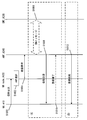
- FIG. 1 is a diagram schematically illustrating a mobile communication system.
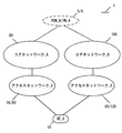
- FIG. 2 is a diagram illustrating an example of a configuration of an access network in a mobile communication system.
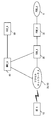
- FIG. 3 is a diagram illustrating an example of a configuration and the like of a core network_A in a mobile communication system.
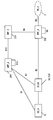
- FIG. 3 is a diagram illustrating an example of a configuration and the like of a core network_B in a mobile communication system.
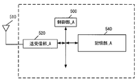
- FIG. 3 is a diagram illustrating a device configuration of a UE.
- FIG. 3 is a diagram illustrating a device configuration of eNB / NR @ node.
- FIG. 3 is a diagram illustrating a device configuration of an MME / AMF.
- FIG. 1 is a diagram schematically illustrating a mobile communication system.
- FIG. 2 is a diagram illustrating an example of a configuration of an access network in a mobile communication system.
- FIG. 3 is a diagram illustrating an example of a configuration and the like of
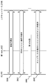
- FIG. 3 is a diagram showing a device configuration of SMF / PGW / UPF. It is a figure showing an initial procedure. It is a figure showing a registration procedure.
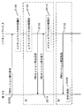
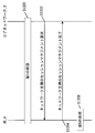
- FIG. 11 is a diagram showing a PDU session establishment procedure. It is a figure which shows the session management procedure led by the network.
- a mobile communication system 1 includes a terminal device (also referred to as a user device or a mobile terminal device) UE (User Equipment) _A10, an access network (AN; Access Network) _A, and an access network_B.
- UE User Equipment
- AN Access Network
- B Access network
- the combination of the access network _A and the core network _A90 may be referred to as EPS (Evolved Packet System; 4G mobile communication system), or the combination of the access network _B, the core network _B190, and the UE_A10 may be referred to as 5GS (5G System ; 5G mobile communication system), and the configurations of 5GS and EPS need not be limited to these.
- UE_A10 can be connected to a network service through 3GPP access (also referred to as 3GPP access or 3GPP access network) and / or non-3GPP access (also referred to as non-3GPP access or non-3GPP access network).
- Device may be used.
- UE_A10 may include a UICC (Universal Integrated Circuit Card) or an eUICC (Embedded UICC).
- UE_A10 may be a terminal device that can be wirelessly connected, or may be a mobile equipment (ME), a mobile station (MS), or a cellular Internet of Things (CIoT) terminal (CIoT UE).
- ME mobile equipment
- MS mobile station
- CIoT cellular Internet of Things
- UE_A10 can also be connected to an access network and / or a core network. Further, UE_A10 can be connected to DN_A and / or PDN_A via an access network and / or a core network. UE_A10 transmits and receives user data to and from DN_A and / or PDN_A using a PDU (Protocol Data Unit or Packet Data Unit) session and / or a PDN (Packet Data Network) connection (also referred to as a PDN connection). ). Furthermore, communication of user data is not limited to IP (Internet Protocol) communication (IPv4 or IPv6) .For example, EPS may be non-IP communication, or 5GS may be Ethernet (registered trademark) communication or Unstructured communication. There may be.
- IP Internet Protocol
- IPv4 or IPv6 IP (Internet Protocol) communication
- EPS may be non-IP communication
- 5GS may be Ethernet (registered trademark) communication or Unstructured communication. There may be.
- the PDU session is the connectivity established between UE_A10 and DN_A5 in order to provide a PDU connection service. More specifically, the PDU session may be a connectivity established between UE_A10 and a foreign gateway.
- the external gateway may be a UPF, a PGW (Packet Data Network Network), or the like.
- the PDU session may be a communication path established for transmitting and receiving user data between UE_A10 and the core network and / or the DN, or may be a communication path for transmitting and receiving PDUs.
- the PDU session may be a session established between the UE_A10 and the core network and / or the DN, and is configured by a logical path configured by one or more bearers or the like between devices in the mobile communication system 1. Communication channel may be used. More specifically, the PDU session may be a connection established between UE_A10 and core network_B190 and / or an external gateway, or a connection established between UE_A10 and UPF. Also, the PDU session may be the connectivity and / or connection between UE_A10 and UPF_A235 via NR node_A122. Further, the PDU session may be identified by a PDU session ID and / or an EPS bearer ID.
- UE_A10 can execute transmission and reception of user data with a device such as an application server arranged in DN_A5 using a PDU session.
- the PDU session can transfer user data transmitted and received between UE_A10 and a device such as an application server located in DN_A5.
- each device UE_A10, a device in the access network, and / or a device in the core network, and / or a device in the data network
- identification information include APN (Access Point Name), TFT (Traffic Flow Template), session type, application identification information, DN_A5 identification information, NSI (Network Slice Instance) identification information, and DCN (Dedicated Core Network). ) At least one of the identification information and the access network identification information may be included, and other information may be further included. Further, when a plurality of PDU sessions are established, each piece of identification information associated with the PDU session may have the same content or different content. Further, the NSI identification information is information for identifying the NSI, and may be NSI ID or Slice Instance ID.
- UTRAN Universal Terrestrial Radio Access Network
- E-UTRAN Evolved Universal Terrestrial Radio Access Network
- NG-RAN 5G- RAN
- UTRAN_A20 and / or E-UTRAN_A80 and / or NG-RAN_A120 are referred to as 3GPP access or 3GPP access network
- wireless LAN access network and non-3GPPGPAN are non-3GPP access or non-3GPP access network. It may be called.
- Each wireless access network includes a device (eg, a base station device or an access point) to which UE_A10 is actually connected.
- E-UTRAN_A80 is an LTE access network and includes one or more eNB_A45.
- eNB_A45 is a radio base station to which UE_A10 connects by E-UTRA (Evolved Universal Terrestrial Radio Access).
- E-UTRA Evolved Universal Terrestrial Radio Access
- each eNB may be connected to each other.
- NG-RAN_A120 is a 5G access network, which may be the (R) AN described in FIG. 4, including one or more NR nodes (New Radio Access Technology nodes) _A122 and / or ng-eNB. Be composed.
- NR @ node_A122 is a wireless base station to which UE_A10 is connected in 5G wireless access (5G @ Radio @ Access), and is also referred to as gNB.
- the ng-eNB may be an eNB (E-UTRA) constituting a 5G access network, and may be connected to the core network_B190 via the NR node_A or may be directly connected to the core network_B190. May be.
- E-UTRA eNB
- each NR ⁇ node_A122 and / or ng-eNB may be connected to each other.
- NG-RAN_A120 may be an access network configured with E-UTRA and / or 5G Radio Access.
- NG-RAN_A120 may include eNB_A45, NRnode_A122, or both.
- eNB_A45 and NR @ node_A122 may be the same device. Therefore, NR node_A122 can be replaced with eNB_A45.
- UTRAN_A20 is an access network of the 3G mobile communication system, and includes an RNC (Radio Network Controller) _A24 and an NB (Node) B) _A22.
- NB_A22 is a radio base station to which UE_A10 connects by UTRA (Universal @ Terrestrial @ Radio @ Access), and UTRAN_A20 may include one or more radio base stations.
- the RNC_A24 is a control unit that connects the core network_A90 and the NB_A22, and the UTRAN_A20 may include one or more RNCs. Also, the RNC_A24 may be connected to one or more NB_A22.
- UE_A10 being connected to each radio access network means being connected to a base station device, an access point, or the like included in each radio access network, and transmitting and receiving data and signals. Is also via a base station device or an access point.
- the control message transmitted and received between UE_A10 and core network_B190 may be the same control message regardless of the type of access network. Therefore, transmitting and receiving a message between the UE_A10 and the core network_B190 via the NRAnode_A122 may be the same as transmitting a message between the UE_A10 and the core network_B190 via the eNB_A45.
- the access network is a wireless network connected to UE_A10 and / or the core network.
- the access network may be a 3GPP access network or a non-3GPP access network.
- the 3GPP access network may be UTRAN_A20, E-UTRAN_A80, NG-RAN (Radio Access Network) _A120, and the non-3GPP access network may be a wireless LAN access point (WLAN AN).
- WLAN AN wireless LAN access point
- UE_A10 may connect to the access network to connect to the core network, or may connect to the core network via the access network.
- DNDN_A5 and PDN_A6 are data networks (Data @ Network) that provide communication services to UE_A10, and may be configured as a packet data service network or may be configured for each service. Further, DN_A5 may include a connected communication terminal. Therefore, connecting to DN_A5 may be connecting to a communication terminal or server device arranged in DN_A5. Further, transmitting / receiving user data to / from DN_A5 may be transmitting / receiving user data to / from a communication terminal or server device arranged in DN_A5. Although DN_A5 is outside the core network in FIG. 1, it may be inside the core network.
- the core network_A90 and / or the core network_B190 may be configured as devices in one or more core networks.
- the devices in the core network may be devices that execute some or all of the processing or functions of each device included in the core network_A90 and / or the core network_B190.
- a device in the core network may be referred to as a core network device.
- the core network refers to an IP mobile communication network operated by a mobile communication operator (MNO; Mobile Network Operator) connected to the access network and / or the DN.
- the core network may be a core network for a mobile communication company that operates and manages the mobile communication system 1, or a virtual mobile communication carrier such as MVNO (Mobile Virtual Network Operator), MVNE (Mobile Virtual Network Enabler), or a virtual mobile communication carrier. It may be a core network for a mobile communication service provider.
- the core network_A90 may be an EPC (Evolved @ Packet @ Core) constituting an EPS (Evolved @ Packet @ System), and the core network_B190 may be a 5GC (5G @ Core @ Network) constituting a 5GS.
- the core network_B190 may be a core network of a system that provides a 5G communication service.
- the EPC may be the core network_A90
- the 5GC may be the core network_B190.
- the core network_A90 and / or the core network_B190 are not limited to this, and may be networks for providing mobile communication services.
- the core network_A90 includes HSS (Home Subscriber Server) _A50, AAA (Authentication Authorization Accounting), PCRF (Policy and Charging Rules), PGW_A30, ePDG, SGW_A35, MME (Mobility Management Entity) _A40, SGSN (Serving GPRS Support Node) and SCEF may be included. These may be configured as an NF (Network Function). The NF may refer to a processing function configured in the network. Further, the core network_A90 can be connected to a plurality of radio access networks (UTRAN_A20, E-UTRAN_A80).
- HSS_A50 HSS
- PGW_A30 PGW
- SGW_A35 SGW
- MME_A40 MME
- DN_A5 and / or PDN_A6 is also called DN or PDN.
- PGW_A30 is a relay device that is connected to DN, SGW_A35, ePDG, WLAN ⁇ ANa70, PCRF, and AAA, and transfers user data as a gateway between DN (DN_A5 and / or PDN_A6) and core network_A90.
- the PGW_A30 may be a gateway for IP communication and / or non-IP communication.
- the PGW_A30 may have a function of transferring IP communication, or may have a function of converting non-IP communication and IP communication.
- a plurality of such gateways may be arranged in the core network_A90. Further, a plurality of arranged gateways may be gateways connecting the core network_A90 and a single DN.
- the U-Plane (User @ Plane; @UP) may be a communication path for transmitting and receiving user data, or may be configured by a plurality of bearers. Further, the C-Plane (Control @ Plane; $ CP) may be a communication path for transmitting and receiving a control message, or may be composed of a plurality of bearers.
- PGW_A30 may be connected to SGW and DN and UPF (User plane function) and / or SMF (Session Management function), or may be connected to UE_A10 via U-Plane. Further, PGW_A30 may be configured together with UPF_A235 and / or SMF_A230.
- the MME_A40 is a control device that is connected to the SGW_A35, the access network, the HSS_A50, and the SCEF, and performs location information management including mobility management of the UE_A10 via the access network and access control. Further, MME_A40 may include a function as a session management device that manages a session established by UE_A10. Further, a plurality of such control devices may be arranged in the core network_A90. For example, a location management device different from the MME_A40 may be configured. A location management device different from MME_A40 may be connected to SGW_A35, an access network, SCEF, and HSS_A50, similarly to MME_A40. Further, MME_A40 may be connected to AMF (Access / Mobility / Management / Function).
- AMF Access / Mobility / Management / Function
- the MMEs may be connected to each other. Thereby, transmission and reception of the context of UE_A10 may be performed between MMEs.
- the MME_A40 is a management device that transmits and receives the control information related to the mobility management and the session management to and from the UE_A10.
- the MME_A40 may be a management device configured in one or more core networks or DCNs or NSIs, or may include one or more core networks or It may be a management device connected to DCN or NSI.
- the plurality of DCNs or NSIs may be operated by a single communication carrier or may be operated by different communication carriers.
- MME_A40 may be a relay device that transfers user data as a gateway between core network_A90 and the access network.
- the user data transmitted and received by the MME_A40 as a gateway may be small data.
- MME_A40 may be an NF that plays a role of mobility management such as UE_A10, or may be an NF that manages one or a plurality of NSIs. MME_A40 may be an NF that plays one or more of these roles.
- the NF may be one or more devices arranged in the core network _A90, and a CP function for control information and / or a control message (hereinafter, CPF (Control Plane Function) or Control Plane Network Function). ) Or a shared CP function shared between a plurality of network slices.
- CPF Control Plane Function
- Control Plane Network Function Control Plane Network Function
- NF is a processing function configured in the network. That is, the NF may be a functional device such as an MME, an SGW, a PGW, a CPF, an AMF, an SMF, or an UPF, or a function or capability capability information such as an MM (Mobility Management) or an SM (Session Management). Further, the NF may be a functional device for realizing a single function or a functional device for realizing a plurality of functions. For example, the NF for realizing the MM function and the NF for realizing the SM function may exist separately, or the NF for realizing both the MM function and the SM function exists. You may.
- HSS_A50 is a management node that is connected to MME_A40, AAA, and SCEF and manages subscriber information.
- the subscriber information of HSS_A50 is referred to, for example, at the time of access control of MME_A40.
- HSS_A50 may be connected to a location management device different from MME_A40.
- HSS_A50 may be connected to CPF_A140.
- HSS_A50 and the UDM (Unified Data Management) _A245 may be configured as different devices and / or NFs, or may be configured as the same device and / or NF.
- AAA is connected to PGW30, HSS_A50, PCRF, and WLAN ANa70, and performs access control of UE_A10 connected via WLAN ANa70.
- PCRF is connected to PGW_A30, WLAN ANa75, AAA, DN_A5, and / or PDN_A6, and performs QoS management for data delivery. For example, it manages the QoS of the communication path between UE_A10 and DN_A5 and / or PDN_A6.
- the PCRF may be a device that creates and / or manages a PCC (Policy and Charging Control) rule and / or a routing rule used when each device transmits and receives user data.
- PCC Policy and Charging Control
- the PCRF may be a PCF that creates and / or manages policies. More specifically, the PCRF may be connected to UPF_A235.
- the ePDG is connected to the PGW 30 and the WLAN ANb75, and performs delivery of user data as a gateway between the core network_A90 and the WLAN ANb75.
- the SGSN is connected to UTRAN_A20, GERAN and SGW_A35, and is a control device for location management between the 3G / 2G access network (UTRAN / GERAN) and the LTE (4G) access network (E-UTRAN). It is. Further, the SGSN has a function of selecting the PGW and the SGW, a function of managing the time zone of the UE_A10, and a function of selecting the MME_A40 at the time of handover to the E-UTRAN.
- the SCEF is a relay device that is connected to DN_A5 and / or PDN_A6, MME_A40, and HSS_A50, and transfers user data as a gateway that connects DN_A5 and / or PDN_A6 and core network_A90.
- SCEF may be a gateway for non-IP communication.
- SCEF may have a function of converting non-IP communication and IP communication.
- a plurality of such gateways may be arranged in the core network_A90.
- a plurality of gateways for connecting the core network_A90 with a single DN_A5 and / or PDN_A6 and / or DN may be provided.
- the SCEF may be configured outside the core network or may be configured inside the core network.
- the core network_B190 includes AUSF (Authentication Server Function), AMF (Access and Mobility Management Function) _A240, UDSF (Unstructured Data Storage Function), NEF (Network Exposure Function), NRF (Network Repository Function), PCF (Policy Control Function), SMF (Session Management Function) _A230, UDM (Unified Data Management), UPF (User Plane Function) _A235, AF (Application Function), N3IWF (Non-3GPP InterWorking Function), at least one of them may be included. . These may be configured as an NF (Network Function). The NF may refer to a processing function configured in the network.
- AMF_A240 AMF
- SMF_A230 SMF
- UPF_A235 UPF
- DN_A5 DN
- FIG. 4 also shows an N1 interface (hereinafter also referred to as a reference point), an N2 interface, an N3 interface, an N4 interface, an N6 interface, an N9 interface, and an N11 interface.
- the N1 interface is an interface between the UE and the AMF
- the N2 interface is an interface between the (R) AN (access network) and the AMF
- the N3 interface is a (R) AN (access network).
- the interface between UPF, the N4 interface is the interface between SMF and UPF, the N6 interface is the interface between UPF and DN, and the N9 interface is the interface between UPF and UPF.
- N11 interface is the interface between AMF and SMF. Using these interfaces, communication can be performed between the devices.
- (R) AN is also referred to as NG RAN hereinafter.
- AMF_A240 is connected to other AMF, SMF (SMF_A230), access network (that is, UTRAN_A20, E-UTRAN_A80, and NG-RAN_A120), UDM, AUSF, and PCF.
- SMF SMF
- AMF_A240 is registration management (Registration management), connection management (Connection management), reachability management (Reachability management), mobility management (Mobility management) such as UE_A10, transfer of SM (Session Management) message between UE and SMF , Access authentication (Access Authentication, Access Authorization), security anchor function (SEA; Security Anchor Function), security context management (SCM; Security Context Management), support of N2 interface for N3IWF, NAS signal with UE via N3IWF It may have a role of supporting transmission / reception, authentication of a UE connected via the N3IWF, management of an RM state (Registration Management State), management of a CM state (Connection Management State), and the like.
- SM Session Management
- SEA Security Anchor Function
- SCM Security Context Management
- AMF_A240s may be arranged in the core network_B190.
- AMF_A240 may be an NF that manages one or more NSIs (Network ⁇ Slice ⁇ Instances).
- the AMF_A240 may be a shared CP function (CCNF; Control Plane Network Function) shared by a plurality of NSIs.
- CCNF Control Plane Network Function
- the RM state includes a non-registered state (RM-DEREGISTERED @ state) and a registered state (RM-REGISTERED @ state).
- RM-DEREGISTERED since the UE is not registered in the network, the AMF cannot reach the UE because the UE context in the AMF does not have information on the location or routing that is valid for the UE. is there.
- the UE in the RM-REGISTERED state, since the UE is registered in the network, the UE can receive a service that requires registration with the network.
- CMThe CM state includes a non-connection state (CM-IDLE @ state) and a connection state (CM-CONNECTED @ state).
- CM-IDLE non-connection state
- CM-CONNECTED connection state
- the UE In the CM-IDLE state, the UE is in the RM-REGISTERED state but does not have a NAS signaling connection established with the AMF via the N1 interface.
- the UE does not have the connection of the N2 interface (N2Nconnection) and the connection of the N3 interface (N3 connection).
- N2Nconnection the connection of the N3 interface
- N3 connection connection of the N3 interface
- the NAS signaling connection NAS signaling connection
- the UE may have a connection of the N2 interface (N2) connection) and / or a connection of the N3 interface (N3 connection).
- SMF_A230 has a session management (Session Management; SM) function such as a PDU session, an IP address allocation (IP address) for UE and its management function, a UPF selection and control function, and a traffic to an appropriate destination.
- SM Session Management
- Each session may have a function of providing SM information, a function of determining an SSC mode (Session ⁇ Service ⁇ Continuity ⁇ mode) for a session, a roaming function, and the like.
- the SMF_A230 may be connected to the AMF_A240, the UPF_A235, the UDM, and the PCF.
- UPUPF_A235 is also connected to DN_A5, SMF_A230, other UPFs, and access networks (that is, UTRAN_A20, E-UTRAN_A80, and NG-RAN_A120).
- UPF_A235 is an anchor for intra-RAT mobility or inter-RAT mobility, packet routing and forwarding (Packet routing & forwarding), UL CL (Uplink Classifier) function that supports routing of multiple traffic flows to one DN, Branching point function that supports multi-homed PDU session (multi-homed PDU session), QoS processing for user plane, verification of uplink traffic (verification), buffering of downlink packet, downlink data notification (Downlink Data Notification) It may have a role such as a trigger function.
- Packet routing & forwarding Packet routing & forwarding
- UL CL Uplink Classifier
- branching point function that supports multi-homed PDU session (multi-homed PDU session)
- QoS processing for user plane verification of uplink traffic (verification
- the UPF_A235 may be a relay device that transfers user data as a gateway between the DN_A5 and the core network_B190.
- the UPF_A235 may be a gateway for IP communication and / or non-IP communication.
- the UPF_A235 may have a function of transferring IP communication, and may have a function of converting non-IP communication and IP communication.
- a plurality of arranged gateways may be gateways connecting the core network_B190 and a single DN.
- the UPF_A235 may have connectivity with another NF, or may be connected to each device via another NF.
- a UPF_C239 (also referred to as a branching point or an uplink classifier), which is a UPF different from the UPF_A235, may exist as a device or an NF. If UPF_C239 is present, a PDU session between UE_A10 and DN_A5 will be established via the access network, UPF_C239, UPF_A235.
- AUAUSF is connected to UDM and AMF_A240. AUSF functions as an authentication server.
- UDSF provides a function for all NFs to store and retrieve information as unstructured data.
- NEF will provide a means to securely provide services and capabilities provided by the 3GPP network.
- Information received from other NFs is stored as structured data (structured data).
- the NRF Upon receiving an NF discovery request (NF ⁇ Discovery Request) from the NF instance, the NRF provides the NF with information on the discovered NF instance, and information on available NF instances and services supported by the instance. Or hold.
- NF ⁇ Discovery Request NF ⁇ Discovery Request
- PCF is connected to SMF (SMF_A230), AF, and AMF_A240. Provides policy rules (policy rule), etc.
- UDM is connected to AMF_A240, SMF (SMF_A230), AUSF, and PCF.
- UDM includes UDM FE (application front end) and UDR (User Data Repository).
- the UDM FE performs processes such as authentication information (credentials), location management (location @ management), and subscriber management (subscription @ management).
- the UDR stores the data required by the UDM ⁇ FE and the policy profiles required by the PCF.
- AF is connected to PCF. AF affects traffic routing and is involved in policy control.
- the N3IWF establishes an IPsec tunnel with the UE, relays NAS (N1) signaling between the UE and the AMF, processes N2 signaling sent from the SMF and relayed by the AMF, and establishes IPsec Security Association (IPsec SA) , Provides functions such as relaying user-plane packets between the UE and the UPF, and selecting AMF.
- IPsec SA IPsec Security Association
- each device may operate on physical hardware, or may be logical hardware virtually configured on general-purpose hardware. It may operate on hardware.
- UE_A10 includes a control unit_A500, a transmission / reception unit_A520, and a storage unit_A540.
- the transmission / reception unit_A520 and the storage unit_A540 are connected to the control unit_A500 via a bus.
- an external antenna 410 is connected to the transmission / reception unit_A520.
- the control unit_A500 is a functional unit for controlling the entire UE_A10, and realizes various processes of the entire UE_A10 by reading and executing various information and programs stored in the storage unit_A540.
- the transmitting / receiving unit _A520 is a functional unit for UE_A10 to connect to a base station (UTRAN_A20, E-UTRAN_A80, and NG-RAN_A120) and / or a wireless LAN access point (WLAN AN) in the access network and to connect to the access network. is there.
- UE_A10 can connect to a base station and / or an access point in an access network via external antenna 410 connected to transmitting / receiving section_A520.
- UE_A10 transmits / receives user data and / or control information to / from a base station and / or an access point in an access network via an external antenna 410 connected to the transmission / reception unit_A520. Can be.
- the storage unit_A540 is a functional unit that stores programs, data, and the like necessary for each operation of the UE_A10, and includes, for example, a semiconductor memory, an HDD (Hard Disk Drive), an SSD (Solid State Drive), and the like.
- the storage unit_A540 stores identification information, control information, flags, parameters, rules, policies, and the like included in a control message transmitted and received in a communication procedure described below.
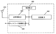
- the eNB_A45 and the NR node_A122 include a control unit_B600, a network connection unit_B620, a transmission / reception unit_B630, and a storage unit_B640.
- the network connection unit_B620, the transmission / reception unit_B630, and the storage unit_B640 are connected to the control unit_B600 via a bus.
- an external antenna 510 is connected to the transmitting / receiving section_B630.
- the control unit_B600 is a functional unit for controlling the entire eNB_A45 and NR node_A122, and reads out and executes various information and programs stored in the storage unit_B640, thereby controlling the entire eNB_A45 and NR node_A122. Implement various processes.
- Transmitting / receiving section_B630 is a functional section for connecting eNB_A45 and NR node_A122 to UE_A10.
- the eNB_A45 and the NR node_A122 can transmit / receive user data and / or control information to / from the UE_A10 via the transmission / reception unit_B630.
- Storage unit_B640 is a functional unit that stores programs, data, and the like necessary for each operation of eNB_A45 and NR node_A122.
- the storage unit_B640 includes, for example, a semiconductor memory, an HDD, an SSD, and the like.
- the storage unit_B640 stores identification information, control information, flags, parameters, and the like included in a control message transmitted and received in a communication procedure described later.
- the storage unit_B640 may store such information as a context for each UE_A10.
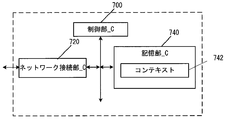
- the MME_A40 or the AMF_A240 includes a control unit_C700, a network connection unit_C720, and a storage unit_C740.
- the network connection unit_C720 and the storage unit_C740 are connected to the control unit_C700 via a bus.
- the storage unit_C740 stores a context 642.
- the control unit_C700 is a functional unit for controlling the entire MME_A40 or AMF_A240, and realizes various processes of the entire AMF_A240 by reading and executing various information and programs stored in the storage unit_C740. I do.
- Network connection unit_C720 MME_A40 or AMF_A240, other MME_A40, AMF_240, SMF_A230, base station in the access network (UTRAN_A20 and E-UTRAN_A80 and NG-RAN_A120) and / or wireless LAN access point (WLAN AN), UDM , AUSF, PCF.
- MME_A40 or AMF_A240 transmits / receives user data and / or control information to / from a base station and / or access point in the access network, UDM, AUSF, and PCF via the network connection unit_C720. Can be.
- Storage unit_C740 is a functional unit that stores programs, data, and the like necessary for each operation of MME_A40 or AMF_A240.
- the storage unit_C740 includes, for example, a semiconductor memory, an HDD, an SSD, and the like.
- the storage unit_C740 stores identification information, control information, flags, parameters, and the like included in a control message transmitted and received in a communication procedure described later.
- the context 642 stored in the storage unit_C740 may include a context stored for each UE, a context stored for each PDU session, and a context stored for each bearer.
- the context stored for each PDU session may include APN in Use, Assigned Session Type, IP Address (es), PGW F-TEID, SCEF ID, and Default bearer.
- the context stored for each bearer includes EPS Bearer ID, TI, TFT, SGW F-TEID, PGW F-TEID, MME F-TEID, eNB Address, NR node Address, WAG Address, eNB ID, NR node ID and WAGID may be included.
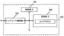
- the SMF_A230 includes a control unit_D800, a network connection unit_D820, and a storage unit_D840.
- the network connection unit_D820 and the storage unit_D840 are connected to the control unit_D800 via a bus. Further, the storage unit_D840 stores a context 742.
- the control unit_D800 of the SMF_A230 is a functional unit for controlling the entire SMF_A230, and realizes various processes of the entire SMF_A230 by reading out and executing various information and programs stored in the storage unit_D840. I do.
- the network connection unit_D820 of the SMF_A230 is a functional unit for the SMF_A230 to connect to the AMF_A240, UPF_A235, UDM, and PCF.
- the SMF_A230 can transmit / receive user data and / or control information to / from the AMF_A240, UPF_A235, UDM, PCF via the network connection unit_D820.
- the storage unit_D840 of the SMF_A230 ⁇ is a functional unit that stores programs, data, and the like necessary for each operation of the SMF_A230.
- the storage unit_D840 of the SMF_A230 includes, for example, a semiconductor memory, an HDD, an SSD, and the like.
- the storage unit_D840 of the SMF_A230 stores identification information, control information, flags, parameters, and the like included in control messages transmitted and received in a communication procedure described later.
- the context 742 stored in the storage unit _D840 of the SMF_A230 a context stored for each UE, a context stored for each APN, a context stored for each PDU session, and stored for each bearer There may be contexts.
- the context stored for each UE may include IMSI, ME Identity, MSISDN, RAT type.
- the context stored for each APN may include APN ⁇ in ⁇ use.
- the context stored for each APN may be stored for each Data ⁇ Network ⁇ Identifier.
- the context stored for each PDU session may include Assigned Session Type, IP Address (es), SGW F-TEID, PGWF-TEID, and Default Bearer.
- the context stored for each bearer may include EPS Bearer ID, TFT, SGW F-TEID, and PGW F-TEID.
- FIG. 8 shows a device configuration example of the PGW_A30 or the UPF_A235.
- PGW_A30 or UPF_A235 includes a control unit_D800, a network connection unit_D820, and a storage unit_D840, respectively.
- the network connection unit_D820 and the storage unit_D840 are connected to the control unit_D800 via a bus. Further, the storage unit_D840 stores a context 742.
- the control unit _D800 of the PGW_A30 or the UPF_A235 is a functional unit for controlling the entire PGW_A30 or the UPF_A235, and reads and executes various information and programs stored in the storage unit _D840 to execute the PGW_A30 or the UPF_A235. Implement the entire process.
- the network connection unit D820 of the PGW_A30 or the UPF_A235 is such that the PGW_A30 or the UPF_A235 is connected to the DN (that is, DN_A5), the SMF_A230, another UPF_A235, and the access network (that is, UTRAN_A20, E-UTRAN_A80, and NG-RAN_A120). It is a functional part for performing.
- UPF_A235 via the network connection _D820, DN (that is, DN_A5), SMF_A230, other UPF_A235, and access network (that is, UTRAN_A20 and E-UTRAN_A80 and NG-RAN_A120), User data and / or control information can be sent and received.
- DN that is, DN_A5
- SMF_A230 other UPF_A235
- access network that is, UTRAN_A20 and E-UTRAN_A80 and NG-RAN_A120
- the storage unit_D840 of the UPF_A235 is a functional unit that stores programs, data, and the like necessary for each operation of the UPF_A235.
- the storage unit_D840 of the UPF_A235 includes, for example, a semiconductor memory, an HDD, an SSD, and the like.
- the storage unit_D840 of the UPF_A235 stores identification information, control information, flags, parameters, and the like included in control messages transmitted and received in a communication procedure described later.
- a context stored for each UE a context stored for each APN, a context stored for each PDU session, and stored for each bearer There may be contexts.
- the context stored for each UE may include IMSI, ME Identity, MSISDN, RAT type.
- the context stored for each APN may include APN ⁇ in ⁇ use.
- the context stored for each APN may be stored for each Data ⁇ Network ⁇ Identifier.
- the context stored for each PDU session may include Assigned Session Type, IP Address (es), SGW F-TEID, PGWF-TEID, and Default Bearer.
- the context stored for each bearer may include EPS Bearer ID, TFT, SGW F-TEID, and PGW F-TEID.
- IMSI International Mobile Subscriber Identity
- MME_A40 / CPF_A140 / AMF_A2400, and SGW_A35 may be equal to the IMSI stored by HSS_A50.
- EMM State / MM State indicates a mobility management state of UE_A10 or MME_A40 / CPF_A140 / AMF_A240.
- EMM @ State / MM @ State may be an EMM-REGISTERED state where UE_A10 is registered in the network (registered state) and / or an EMM-DEREGISTERD state where UE_A10 is not registered in the network (unregistered state).
- the EMM @ State / MM @ State may be an ECM-CONNECTED state in which the connection between the UE_A10 and the core network is maintained, and / or an ECM-IDLE state in which the connection is released.
- EMM @ State / MM @ State may be information that can distinguish between a state in which UE_A10 is registered in the EPC and a state in which UE_A10 is registered in NGC or 5GC.
- GUTI Globally Unique Temporary Identity
- MME_A40 / CPF_A140 / AMF_A240 identification information GUMMEI (Globally Unique MME Identifier)
- M-TMSI M-Temporary Mobile Subscriber Identity
- ME @ Identity is the ID of UE_A10 or ME, and may be, for example, IMEI (International Mobile Equipment Identity) or IMEISV (IMEI Software Version).
- MSISDN represents the basic telephone number of UE_A10.
- MSISDN stored in MME_A40 / CPF_A140 / AMF_A240 may be the information indicated by the storage unit of HSS_A50.
- GUTI may include information for identifying CPF_140.
- ⁇ MME ⁇ F-TEID is information for identifying MME_A40 / CPF_A140 / AMF_A240.
- the MME F-TEID may include the IP address of MME_A40 / CPF_A140 / AMF_A240, or may include the TEID (Tunnel / Endpoint Identifier) of MME_A40 / CPF_A140 / AMF_A240, or may include both of them. Is also good.
- the IP address of MME_A40 / CPF_A140 / AMF_A240 and the TEID of MME_A40 / CPF_A140 / AMF_A240 may be stored independently.
- the MME @ F-TEID may be identification information for user data or identification information for control information.
- ⁇ SGW ⁇ F-TEID is information for identifying SGW_A35.
- the SGW F-TEID may include the IP address of the SGW_A35, may include the TEID of the SGW_A35, or may include both of them. Further, the IP address of SGW_A35 and the TEID of SGW_A35 may be stored independently. Further, the SGW @ F-TEID may be identification information for user data or identification information for control information.
- ⁇ PGW ⁇ F-TEID is information for identifying PGW_A30 / UPGW_A130 / SMF_A230 / UPF_A235.
- the PGW F-TEID may include the IP address of PGW_A30 / UPGW_A130 / SMF_A230 / UPF_A235, or may include the TEID of PGW_A30 / UPGW_A130 / SMF_A230 / UPF_A235, or may include both of these. Good.
- IP address of PGW_A30 / UPGW_A130 / SMF_A230 / UPF_A235 and the TEID of PGW_A30 / UPGW_A130 / SMF_A230 / UPF_A235 may be stored independently.
- PGW @ F-TEID may be identification information for user data or identification information for control information.
- ⁇ ENB ⁇ F-TEID is information for identifying eNB_A45.
- the eNB F-TEID may include the IP address of eNB_A45, may include the TEID of eNB_A45, or may include both of them. Further, the IP address of eNB_A45 and the TEID of SGW_A35 may be stored independently. Further, eNB @ F-TEID may be identification information for user data or identification information for control information.
- APN may be identification information for identifying a core network and an external network such as a DN. Further, the APN can be used as information for selecting a gateway such as PGW_A30 / UPGW_A130 / UPF_A235 that connects the core network_A90.
- the APN may be a DNN (Data ⁇ Network ⁇ Name). Therefore, APN may be expressed as DNN, and DNN may be expressed as APN.
- the APN may be identification information for identifying such a gateway, or identification information for identifying an external network such as a DN.
- identification information for identifying such a gateway or identification information for identifying an external network such as a DN.
- ⁇ UE ⁇ Radio ⁇ Access ⁇ Capability is identification information indicating the radio access capability of UE_A10.
- UE Network Capability includes security algorithms and key derivation functions supported by UE_A10.
- MS Network Capability is information that includes one or more pieces of information necessary for SGSN_A42 for UE_A10 having a GERAN_A25 and / or UTRAN_A20 function.
- Access @ Restriction is registration information of access restriction.
- eNB @ Address is the IP address of eNB_A45.
- MME UE S1AP ID is information for identifying UE_A10 in MME_A40 / CPF_A140 / AMF_A240.
- eNB ⁇ UE ⁇ S1AP ⁇ ID is information for identifying UE_A10 in eNB_A45.
- APN in Use is the recently used APN.
- APN ⁇ in ⁇ Use may be Data ⁇ Network ⁇ Identifier. This APN may be composed of network identification information and default operator identification information. Further, APN @ in @ Use may be information for identifying the DN at which the PDU session is established.
- Type is information indicating the type of the PDU session.
- Assigned Session Type may be Assigned PDN Type.
- the type of the PDU session may be IP or non-IP.
- IP it may further include information indicating the type of PDN allocated from the network.
- the Assigned Session Type may be IPv4, IPv6, or IPv4v6.
- IP @ Address is the IP address assigned to the UE.
- the IP address may be an IPv4 address, an IPv6 address, an IPv6 prefix, or an interface ID.
- Assigned Session Type indicates non-IP, the element of IP Address may not be included.
- ⁇ DN ⁇ ID is identification information for identifying the core network_B190 and an external network such as a DN. Furthermore, the DN @ ID can also be used as information for selecting a gateway such as UPGW_A130 or PF_A235 that connects the core network_B190.
- the DN ID may be identification information for identifying such a gateway or identification information for identifying an external network such as a DN.
- the DN ID may be identification information for identifying such a gateway or identification information for identifying an external network such as a DN.
- the DN / ID may be a plurality of gateways that can be selected by the DN / ID.
- one gateway may be selected from among the plurality of gateways by another method using identification information other than the DN @ ID.
- the DN ⁇ ID may be information equal to the APN or information different from the APN. If the DN ID and the APN are different information, each device may manage information indicating the correspondence between the DN ID and the APN, or may perform a procedure for inquiring the APN using the DN ID. Alternatively, a procedure for inquiring the DN @ ID using the APN may be performed.
- ⁇ SCEF ⁇ ID is the IP address of SCEF_A46 used in the PDU session.
- Default @ Bearer is information acquired and / or generated when a PDU session is established, and is EPS bearer identification information for identifying a default bearer (default @ bearer) associated with the PDU session.
- EPS Bearer ID is identification information of the EPS bearer.
- EPS Bearer ID may be identification information for identifying SRB (Signaling Radio Bearer) and / or CRB (Control-plane Radio bearer) or identification information for identifying DRB (Data Radio Bearer).
- TI Transaction @ Identifier
- the EPS @ Bearer @ ID may be EPS bearer identification information for identifying a dedicated bearer. Therefore, identification information for identifying an EPS bearer different from the default bearer may be used.
- TFT indicates all packet filters associated with the EPS bearer.
- the TFT is information for identifying a part of user data to be transmitted and received, and the UE_A10 transmits and receives the user data identified by the TFT using an EPS bearer associated with the TFT.
- UE_A10 transmits / receives the user data identified by the TFT using an RB (Radio Bearer) associated with the TFT.
- the TFT may associate user data such as application data to be transmitted and received with an appropriate transfer path, or may be identification information for identifying application data.
- UE_A10 may transmit and receive user data that cannot be identified by TFT using a default bearer.
- UE_A10 may store in advance a TFT associated with the default bearer.
- ⁇ Default ⁇ Bearer is EPS bearer identification information for identifying the default bearer associated with the PDU session.
- the EPS bearer may be a logical communication path established between UE_A10 and PGW_A30 / UPGW_A130 / UPF_A235, or a communication path configuring a PDN connection / PDU session.
- the EPS bearer may be a default bearer or a dedicated bearer.
- the EPS bearer may be configured to include an RB established between UE_A10 and a base station and / or an access point in the access network. Further, the RB and the EPS bearer may be associated one-to-one.
- the identification information of the RB may be associated one-to-one with the identification information of the EPS bearer, or may be the same identification information.
- RB may be SRB and / or CRB, or DRB.
- Default @ Bearer may be information that UE_A10 and / or SGW_A35 and / or PGW_A30 / UPGW_A130 / SMF_A230 / UPF_A235 acquire from the core network when a PDU session is established.
- the default bearer is an EPS bearer that is first established during a PDN connection / PDU session, and is an EPS bearer that can be established only once during one PDN connection / PDU session.
- the default bearer may be an EPS bearer that can be used for communication of user data that is not associated with a TFT.
- a dedicated bearer is an EPS bearer established after a default bearer is established in a PDN connection / PDU session, and is an EPS bearer that can be established multiple times in one PDN connection / PDU session. is there.
- the dedicated bearer is an EPS bearer that can be used for communication of user data associated with the TFT.
- ⁇ User ⁇ Identity is information for identifying a subscriber.
- User @ Identity may be IMSI or MSISDN. Further, User @ Identity may be identification information other than IMSI and MSISDN.
- Serving ⁇ Node ⁇ Information is information for identifying MME_A40 / CPF_A140 / AMF_A240 used in the PDU session, and may be the IP address of MME_A40 / CPF_A140 / AMF_A240.
- ⁇ ENB ⁇ Address is the IP address of eNB_A45.
- eNB ID is information for identifying the UE in eNB_A45.
- MME @ Address is the IP address of MME_A40 / CPF_A140 / AMF_A240.
- MME ID is information for identifying MME_A40 / CPF_A140 / AMF_A240.
- NR @ node @ Address is the IP address of NR @ node_A122.
- the NR @ node @ ID is information for identifying the NR @ node_A 122.
- WAG @ Address is the IP address of the WAG.
- WAG ID is information for identifying a WAG.
- Anchor or anchor point is a UFP that has a gateway function for DN and PDU sessions.
- the UPF serving as an anchor point may be a PDU session anchor, or may be an anchor.
- the SSC mode indicates a service session continuity (Session5Service Continuity) mode supported by the system and / or each device in the 5GC. More specifically, the mode may indicate the type of service session continuation supported by the PDU session established between UE_A10 and the anchor point).
- the anchor point may be the UPGW or UPF_A235.
- the SSC @ mode may be a mode indicating the type of service session continuation set for each PDU session.
- SSC @ mode may be composed of three modes, SSC @ mode @ 1, SSC @ mode @ 2, and SSC @ mode # 3. SSC @ mode is associated with the anchor point and cannot be changed while the PDU session is established.
- SSC mode 1 in the present embodiment is a mode of service session continuation in which the same UPF is maintained as an anchor point regardless of an access technology such as a RAT (Radio Access Technology) or a cell used when UE_A10 connects to a network. It is. More specifically, SSC ⁇ mode ⁇ 1 may be a mode for realizing the service session continuation without changing the anchor point used by the established PDU session even when the mobility of UE_A10 occurs.
- RAT Radio Access Technology
- SSC mode 2 in the present embodiment includes an anchor point associated with one SSC mode 2 in the PDU session
- the service session continuation that releases the PDU session first and subsequently establishes the PDU session is continued.
- SSC @ mode2 is a mode in which when a relocation of an anchor point occurs, a PDU session is deleted once and a new PDU session is established.
- ⁇ SSC ⁇ mode # 2 is a service session continuation mode in which the same UPF is maintained as an anchor point only in the UPF serving area. More specifically, SSC @ mode2 may be a mode for realizing service session continuation without changing the UPF used by the established PDU session as long as UE_A10 is in the serving area of the UPF. Further, SSC mode 2, such as exiting from the serving area of the UPF, when the mobility of UE_A10 occurs, change the UPF used by the established PDU session, even in the mode to realize the service session continuation Good.
- SSC mode 3 in the present embodiment is a service session continuation mode in which a PDU session can be established between a new anchor point and a UE for the same DN without releasing a PDU session between the UE and the anchor point. is there.
- SSC mode 3 is a PDU session established between UE_A10 and UPF, and / or before disconnecting the communication path, for the same DN, a new PDU session via a new UPF, and / or Alternatively, a service session continuation mode in which a communication path is permitted to be established. Further, SSC @ mode # 3 may be a service session continuation mode in which UE_A10 is allowed to enter multihoming.
- / or SSC mode 3 may be a mode in which service session continuation using a plurality of PDU sessions and / or UPFs associated with the PDU sessions is permitted.
- each device may realize service session continuation using a plurality of PDU sessions, or may realize service session continuation using a plurality of TUPFs.
- the selection of a new UPF may be performed by the network, and the new UPF may be a location where UE_A10 is connected to the network. May be the most suitable UPF. Further, when multiple PDU sessions and / or UPFs used by the PDU sessions are valid, UE_A10 immediately performs correspondence between application and / or flow communication with the newly established PDU session. Or may be performed based on the completion of communication.
- the network refers to at least a part of access network_A20 / 80, access network_B80 / 120, core network_A90, core network_B190, DN_A5, and PDN_A6. Further, at least one device included in at least a part of the access network _A20 / 80, the access network _B80 / 120, the core network _A90, the core network _B190, the DN_A5, and the PDN_A6 is referred to as a network or a network device. It may be called. That is, the fact that the network transmits and receives messages and / or performs procedures means that devices in the network (network devices) transmit and / or receive messages and / or perform procedures.
- a session management (SM; Session Management) message (NAS (Non-Access-Stratum) SM message or SM message) is a procedure for SM (session management procedure or SM procedure) May be a control message transmitted and received between UE_A10 and SMF_A230 via AMF_A240.
- the SM message includes a PDU session establishment request message, a PDU session establishment acceptance message, a PDU session completion message, a PDU session rejection message, a PDU session change request message, a PDU session change acceptance message, a PDU session change rejection message, and the like. You may.
- the procedure for the SM may include a PDU session establishment procedure, a PDU session change procedure, and the like.
- the TA list (TA ⁇ ⁇ list) is a list including one or more TAs assigned to UE_A10 by the network.
- UE_A10 may be able to move without executing the registration procedure while moving within one or more TAs included in the TA list.
- the TA list may be a group of information indicating an area where the UE_A10 can move without executing the registration procedure.
- a network slice (Network @ Slice) is a logical network that provides specific network capabilities and network characteristics.
- the network slice is also referred to as an NW slice.
- NSI Network @ Slice @ Instance
- the NSI in the present embodiment is an entity of a network slice (Network @ Slice) configured in the core network_B190 or one or more.
- the NSI in the present embodiment may be configured by a virtual NF (Network Function) generated using NST (Network Slice Template).
- NST Network Slice Template
- the NST is associated with a resource request for providing a required communication service or capability, and is a logical expression of one or a plurality of Network Function (NF).
- NF Network Function
- the NSI may be an aggregate in the core network_B190 configured by a plurality of NFs.
- the NSI may be a logical network configured to separate user data delivered by a service or the like. At least one NF may be configured in the network slice.
- the NF configured in the network slice may or may not be a device shared with another network slice.
- UE_A10, and / or devices in the network may include NSSAI and / or S-NSSAI and / or UE usage type and / or one or more network slice type IDs and / or one or more NS IDs.
- One or more network slices can be assigned based on registration information and / or APN.
- the S-NSSAI in the present embodiment is an abbreviation of Single ⁇ Network ⁇ Slice ⁇ Selection ⁇ Assistance ⁇ information and is information for identifying a network slice.
- the S-NSSAI may be composed of SST (Slice / Service type) and SD (Slice Differentiator).
- the S-NSSAI may include only the SST, or may include both the SST and the SD.
- the SST is information indicating the operation of the network slice expected in terms of functions and services.
- the SD may be information that complements the SST when one NSI is selected from a plurality of NSIs indicated by the SST.
- the S-NSSAI may be information specific to each PLMN (Public Land Mobile Network), standard information shared between PLMNs, or information specific to a carrier that differs for each PLMN. There may be.
- the SST and / or SD may be standard information (Standard Value) shared between PLMNs, or may be information (Non Standard Value) that is different for each PLMN and is specific to a communication carrier. May be.
- the network may store one or more S-NSSAIs in the registration information of UE_A10 as a default S-NSSAI.
- NSSAI Single Network Slice Selection Assistance information
- UE_A10 may store NSSAI permitted from the network for each PLMN.
- NSSAI may be information used to select AMF_A240.
- the operator A network in the present embodiment is a network operated by the network operator A (operator A).
- the operator A may develop a common NW slice with an operator B described later.
- the operator B network in the present embodiment is a network operated by the network operator B (operator B).
- the operator B may develop a common NW slice with the operator A.
- the first NW slice in the present embodiment is an NW slice to which an established PDU session belongs when the UE connects to a specific DN.
- the first NW slice may be an NW slice managed in the operator A network, or may be an NW slice commonly managed in the operator B network.
- the second NW slice in the present embodiment is an NW slice to which another PDU session that can be connected to the DN to which the PDU session belonging to the first NW slice is connected.
- the first NW slice and the second NW slice may be operated by the same operator or may be operated by different operators.
- Equivalent PLMN in the present embodiment is a PLMN that is treated as if it were the same PLMN as an arbitrary PLMN in the network.
- the DCN (Dedicated Core Network) in the present embodiment is a core network dedicated to a specific subscriber type and configured in the core network_A90.
- a DCN for a UE registered as a user of a Machine to Machine (M2M) communication function may be configured in the core network_A90.
- M2M Machine to Machine
- a default DCN for a UE without an appropriate DCN may be configured in the core network_A90.
- at least one or more MME_40 or SGSN_A42 may be arranged in the DCN, and at least one or more SGW_A35 or PGW_A30 or PCRF_A60 may be arranged.
- a DCN may be identified by a DCN ID, and a UE may be assigned to one DCN based on information such as a UE usage type and / or a DCN ID.
- the first timer in the present embodiment is a timer that manages the start of a procedure for session management such as a PDU session establishment procedure, and / or the transmission of an SM (Session Management) message such as a PDU session establishment request message, Information indicating the value of a back-off timer for managing the behavior of session management may be used.
- SM Session Management
- the first timer and / or the back-off timer may be referred to as a timer.
- each device may be prohibited from starting a procedure for session management and / or transmitting / receiving an SM message.
- the first timer may be set in association with at least one of the congestion management unit applied by the network and / or the congestion management unit identified by the UE.
- the SM message may be a NAS message used in a procedure for session management, and may be a control message transmitted and received between UE_A10 and SMF_A230 via AMF_A240. Further, the SM message includes a PDU session establishment request message, a PDU session establishment acceptance message, a PDU session completion message, a PDU session rejection message, a PDU session change request message, a PDU session change acceptance message, a PDU session change rejection message, and the like. You may. Further, the procedure for session management may include a PDU session establishment procedure, a PDU session change procedure, and the like. In these procedures, a back-off timer value may be included for each message received by UE_A10.
- the UE may set a back-off timer received from the NW as a first timer, may set a timer value by another method, or may set a random value. Also, when the back-off timer received from the NW is configured with a plurality, the UE may manage a plurality of "first timers" according to the plurality of back-off timers, or the UE holds Based on a policy, one timer value may be selected from a plurality of backoff timer values received from the NW, set as the first timer, and managed.
- the UE when receiving two back-off timer values, the UE sets the back-off timer values received from the NW to ⁇ first timer # 1 '' and ⁇ first timer # 2 '', respectively, and manages them. I do. Further, one value may be selected from a plurality of back-off timer values received from the NW based on a policy held by the UE, and may be set as the first timer and managed.
- UE_A10 When UE_A10 receives a plurality of backoff timer values from the network, UE_A10 may manage a plurality of “first timers” corresponding to the plurality of backoff timers.
- first timers In order to distinguish a plurality of "first timers" received by the UE_A10, they may be described as, for example, "first timer # 1" or "first timer # 2".
- the plurality of back-off timers may be obtained by one session management procedure, or may be obtained by different session management procedures.
- the first timer is set for a plurality of related NW slices based on information for identifying one NW slice as described above, and a back-off timer for suppressing reconnection, or an APN /
- the backoff timer may be set in units of a combination of DNN and one NW slice, and may be a back-off timer for preventing reconnection, but is not limited to this, and may be used to identify APN / DNN and one NW slice.
- a backoff timer may be set based on a combination of a plurality of related NW slices based on the backoff timer to suppress reconnection.
- the re-attempt (Re-attempt) information in the present embodiment is information in which the network (NW) instructs the UE_A10 whether to permit reconnection of the rejected PDU session using the same identification information.
- the re-attempt information may be set for each UTRAN access, E-UTRAN access, NR access, or each slice information. Further, the re-attempt information specified in the unit of access may be allowed to reconnect to the network on the assumption that the access is changed. As the re-attempt information specified in slice units, slice information different from the rejected slice may be specified, and reconnection using the specified slice information may be permitted.
- the network slice association rule in the present embodiment is a rule for associating information for identifying a plurality of network slices.
- the network slice association rule may be received in a PDU session rejection message, or may be set in UE_A10 in advance. Further, the most recent network slice association rule in UE_A10 may be applied. Conversely, UE_A10 may perform a behavior based on the latest network slice association rule. For example, when a new network slice association rule is received in the PDU session rejection message in a state where the network slice association rule is set in advance to UE_A10, UE_A10 updates the network slice association rule held in UE_A10. Is also good.
- the priority management rule of the backoff timer in the present embodiment is a rule set in UE_A10 in order to collectively manage a plurality of backoff timers generated in a plurality of PDU sessions into one backoff timer. For example, when contention or overlapping congestion management is applied, and when the UE holds a plurality of back-off timers, UE_A10 is based on a priority management rule of the back-off timer, a plurality of back-off timers May be managed collectively.
- the pattern in which conflict or overlapping congestion management occurs is a case where congestion management based on only DNN and congestion management based on both DNN and slice information are simultaneously applied, and in this case, congestion management based on only DNN. Management takes precedence.
- the priority management rule of the back-off timer is not limited to this. Note that the back-off timer may be the first timer included in the PDU session reject message.
- the first state in the present embodiment is a state in which each device has completed a registration procedure and a PDU session establishment procedure, and UE_A10 and / or each device has one or more of the first to fourth congestion management applied. It is in a state where it is.
- UE_A10 and / or each device may be in a state where UE_A10 is registered in the network (RM-REGISTERED state) due to the completion of the registration procedure, and the completion of the PDU session establishment procedure is that UE_A10 is a PDU from the network. It may be in a state where the session establishment rejection message has been received.
- the congestion management in the present embodiment includes one or a plurality of congestion managements among the first to fourth congestion managements. Note that the control of the UE by the NW is realized by the first timer and the congestion management recognized by the UE, and the UE may store an association between these pieces of information.
- the first congestion management in the present embodiment refers to control signal congestion management for DNN parameters.
- the NW when congestion for DNN #A is detected, if the NW recognizes that it is a UE-led session management request targeting only DNN #A parameters, the NW is the first May be applied.
- the NW may select a default DNN on the initiative of the NW and set it as a congestion management target even when the DNN information is not included in the session management request led by the UE.
- the NW may apply the first congestion management.
- the UE may suppress the UE-initiated session management request targeting only DNN # A.
- the first congestion management in the present embodiment is control signal congestion management for the DNN, and may be congestion management due to the fact that connectivity to the DNN is in a congestion state.
- the first congestion management may be congestion management for restricting connection to DNN # A in all connectivity.
- the connection to DNN # A in all the connections may be a connection of DNN # A in the connectivity using any S-NSSAI available to the UE, and a network slice to which the UE can connect. May be a connection of DNN # A.
- connectivity to DNN # A without a network slice may be included.
- the second congestion management in the present embodiment is control signal congestion management for S-NSSAI, and congestion management due to the network slice selected by S-NSSAI being in a congestion state. May be.
- the second congestion management may be congestion management for regulating all connections based on S-NSSAI # A. That is, it may be congestion management for restricting connections to all DNNs via the network slice selected by S-NSSAI # A.
- the third congestion management in the present embodiment refers to control signal congestion management for DNN and S-NSSAI parameters.
- the NW when the control signal congestion for DNN # A and the control signal congestion for S-NSSAI # A are simultaneously detected, the NW sets the parameters of DNN # A and S-NSSAI # A.
- the NW may apply the third congestion management. Note that the NW may select a default DNN under the initiative of the NW, and may also be a congestion management target even when the session management request led by the UE does not include information indicating the DNN.
- the UE may suppress the UE-initiated session management request for the parameters of DNN # A and S-NSSAI # A.
- the third congestion management in the present embodiment is a control signal congestion management targeting the parameters of the DNN and the S-NSSAI, and to the DNN via the network slice selected based on the S-NSSAI. It may be congestion management due to the connectivity being in a congestion state. For example, the third congestion management may be congestion management for restricting connection to DNN # A among the connectivity based on S-NSSAI # A.
- the fourth congestion management in the present embodiment indicates control signal congestion management for at least one parameter of DNN and / or S-NSSAI.
- the NW when the control signal congestion for the DNN # A and the control signal congestion for the S-NSSAI # A are detected at the same time, the NW has the DNN # A and / or the S-NSSAI # A.
- the NW may apply the fourth congestion management.
- the NW may select a default DNN under the initiative of the NW, and may also be a congestion management target even when the session management request led by the UE does not include information indicating the DNN.
- the UE may suppress a UE-initiated session management request for at least one parameter of DNN # A and / or S-NSSAI # A.
- the fourth congestion management in the present embodiment is control signal congestion management targeting the parameters of DNN and S-NSSAI, and a network slice selected based on S-NSSAI, and connection to DNN. It may be congestion management due to the fact that the nature is in a congestion state.
- the fourth congestion management is congestion management for regulating all connections based on S-NSSAI # A, and congestion for regulating connections to DNN # A in all connectivity. It may be management.
- it is congestion management to regulate connections to all DNNs via the network slice selected by S-NSSAI # A, and to regulate connections to DNN # A in all connectivity. It may be congestion management.
- connection to DNN # A in all the connections may be a connection of DNN # A in the connectivity using any S-NSSAI available to the UE, and a network slice to which the UE can connect. May be a connection of DNN # A. Furthermore, connectivity to DNN # A without a network slice may be included.
- the fourth congestion management using DNN # A and S-NSSAI # A as parameters, the first congestion management using DNN # A as a parameter and the second congestion management using S-NSSAI # A as a parameter May be performed simultaneously.
- the first behavior in the present embodiment is a behavior in which the UE stores the slice information transmitted in the first PDU session establishment request message in association with the transmitted PDU session identification information.
- the UE may store the slice information transmitted in the first PDU session establishment request message, or store the slice information received when the first PDU session establishment request is rejected. May be.
- the second behavior in the present embodiment the UE, using different slice information different from the slice information specified in the first PDU session establishment, to the same APN / DNN as the first PDU session establishment request
- the second behavior the UE, when the backoff timer value received from the network is zero or invalid, using slice information different from the slice information specified in the first PDU session establishment,
- the behavior may be such that a PDU session establishment request for connecting to the same APN / DNN as the first PDU session establishment request is transmitted.
- the first PDU session is rejected because the wireless access of the specific PLMN to which the specified APN / DNN is connected is not supported, or the first PDU session is rejected for temporary reasons.
- the UE connects to the same APN / DNN as the APN / DNN included in the first PDU session establishment request, using slice information different from the slice information specified in the first PDU session establishment. May be a behavior of transmitting a PDU session establishment request for the purpose.
- the third behavior in the present embodiment the UE, when the PDU session establishment request is rejected, until the first timer expires, using the same identification information, send a new PDU session establishment request Behavior.
- the third behavior is that if the UE receives a back-off timer value from the network that is neither zero nor invalid, a new PDU with the same identification information until the first timer expires.
- the behavior that does not transmit the session establishment request may be used.
- the same identification information means that the first identification information and / or the second identification information to be included in the new PDU session establishment request is the first identification information and / or the first identification information transmitted in the rejected PDU session establishment request. Alternatively, it may mean that the second identification information is the same.
- the behavior may be such that a new PDU session establishment request using the same identification information is not transmitted until the first timer expires.
- the PDU session that does not transmit a new PDU session establishment request in the third behavior may be a PDU session to which congestion management associated with the first timer is applied.
- the first timer is a connectivity corresponding to the type of congestion management associated with, and DNN and / or S-NSSAI associated with the congestion management May not be transmitted for a PDU session using a new PDU session establishment request.
- the process in which the UE is prohibited by this behavior may be the start of a procedure for session management including a PDU session establishment request, and / or the transmission and reception of an SM message.
- the fourth behavior in the present embodiment the UE, when the PDU session establishment request is rejected, until the first timer expires, slice information, a new PDU session establishment request that does not carry DNN / APN information Is not transmitted.
- the fourth behavior is that if the back-off timer received by the UE from the network is neither zero nor invalid, until the first timer expires, slice information, a new PDU that does not carry DNN / APN information
- the behavior that does not transmit the session establishment request may be used.
- the fifth behavior in the present embodiment is a behavior in which the UE does not transmit a new PDU session establishment request using the same identification information when the PDU session establishment request is rejected.
- the fifth behavior is that when the UE and the UE and the network support different PDP ⁇ ⁇ ⁇ types and are in the same PLMN, a new PDU session using the same identification information
- the behavior that does not transmit the establishment request may be used.
- the sixth behavior in the present embodiment is a behavior in which the UE transmits a new PDU session establishment request as an initial procedure using the same identification information when the PDU session establishment request is rejected.
- the sixth behavior UE, the first PDU session establishment request, because there is no PDN session context of interest in handover from non-3GPP access, if rejected, the same identification information As an initial procedure, a new PDU session establishment request may be transmitted.
- the seventh behavior in the present embodiment is that, when the UE selects another NW slice in the procedure for selecting the PLMN, the UE continues the back-off timer received when the previous PDU session establishment request was rejected. Behavior. Specifically, the seventh behavior, UE, when the first PDU session establishment request is rejected, in the case of performing PLMN selection, specified in the first PDU session establishment request in the selected PLMN If a common NW slice can be designated as the NW slice, the back-off timer received when the first PDU session establishment request is rejected may be continued.
- the eighth behavior in the present embodiment is a behavior in which the UE sets a value notified from the network or a value previously set in the UE as the first timer value.
- the eighth behavior may be a behavior in which the UE sets the back-off timer value received in the rejection notification of the first PDU session establishment request as the first timer value, or in advance.
- the behavior may be set to the UE or set to a held value as the first timer value. Note that, when the timer is set in the UE in advance or the retained timer is set as the first timer value, the timer may be limited to the time when the mobile terminal is in the HPLMN or the equivalent PLMN.
- the ninth behavior in the present embodiment the UE, when the PDU session establishment request is rejected, terminal power on / off, or until USIM (Universal Subscriber Identity Module), until a new PDU session establishment request This is a behavior that does not send. Specifically, the ninth behavior, the UE, when the back-off timer received from the network is invalid, or the first PDU session rejection reason between the UE and the network PDP type (PDP type) If they are different, a new PDU session establishment request is not transmitted until the terminal is turned on / off or the USIM is unplugged.
- PDP type network PDP type
- the connected PLMN does not transmit a new PDU session establishment request until the terminal power is turned on / off or the USIM is unplugged. May be.
- the connected PLMN does not transmit a new PDU session establishment request until the terminal power is turned on / off or the USIM is unplugged. May be. If the first PDU session is rejected because the specified APN / DNN is not supported by the radio of the connected PLMN, and if the back-off timer from the network is neither zero nor invalid, the terminal powers on.
- tenth behavior in the present embodiment is a behavior in which the UE transmits a new PDU session establishment request when the PDU session establishment request is rejected.
- the tenth behavior is that the UE further notifies the network when the back-off timer received from the network is zero, or when the first PDU session establishment request is rejected for a temporary reason. If there is no back-off timer information element itself, the behavior may be to transmit a new PDU session establishment request.
- the target APN / DNN in the selected PLMN When the back-off timer is not activated or when the back-off timer received from the network is invalid, a behavior of transmitting a new PDU session establishment request may be adopted.
- a new PDU session establishment request may be transmitted.
- the specified APN / DNN is not supported by the connected PLMN radio and the first PDU session is rejected and the back-off timer notified from the network is zero, a new PDU session It may be a behavior of transmitting an establishment request.
- the eleventh behavior in the present embodiment is a behavior in which the UE ignores the first timer and the Re-attempt information.
- the eleventh behavior is that when the UE is rejected because the first PDU session establishment request is in the handover from non-3GPP access because the target PDN session context does not exist, or Because the number of bearers set up in PDN connection has reached the maximum allowed number, if the first PDU session establishment is rejected, the first timer, and the behavior of ignoring the Re-attempt information, Is also good.
- the twelfth behavior in the present embodiment is based on information for identifying one NW slice received by the UE in the rejection notification for the first PDU session establishment request, based on a plurality of associated NW slices This is a behavior in which information for identification is determined, and reconnection to a plurality of related NW slices is suppressed based on the information for identifying one NW slice.
- the twelfth behavior is that the UE identifies another NW slice related to the information for identifying the NW slice notified by the first PDU session establishment request rejection based on the network slice association rule.
- a behavior that derives information for performing the operation may be used.
- the network slice association rule may be set in the UE in advance, or may be notified from the network by a PDU session establishment rejection notification.
- the thirteenth behavior in the present embodiment is different from one or more PDU session establishment by the same UE a plurality of different congestion management is activated, if a plurality of timers are provided from the network, the UE is a back-off timer
- the behavior of managing the timer may be based on the priority management rule. For example, the first PDU session establishment request of the combination of DNN_1 and slice_1 by the UE is set as a congestion management target based on both the DNN and the slice information, and the UE receives the first timer # 1. Further, the UE makes a second PDU session establishment request for the combination of DNN_1 and slice_2, is subjected to congestion management based only on the DNN, and receives the first timer # 2.
- the UE may manage the UE's behavior of reestablishing the PDU session based on the priority management rule of the back-off timer by using the first timer # 2 that has been given priority. Specifically, the timer value held by the UE may be overwritten by the timer value generated by the prioritized congestion control.
- the UE simultaneously manages a plurality of timers (here, first timer # 1 and first timer # 2). Specifically, the UE manages the timer on a session management instance / PDU session basis.
- the UE receives a plurality of timers simultaneously in one session management procedure, the UE simultaneously manages the target back-off timer in the congestion management unit identified by the UE.
- the behavior may be such that a second identification process for identifying the DNN and / or the S-NSSAI associated with the congestion management is performed.
- the first identification processing includes at least one or more pieces of identification information from the first identification information to the fourth piece of identification information, and / or at least one or more pieces of the eighteenth piece of identification information from the eleventh piece of identification information to the eighteenth piece of identification information. The identification may be performed based on the identification information.
- the second identification processing is at least one of the first identification information to the one or more identification information of the fourth identification information, and / or at least the eleventh identification information to the one or more of the eighteenth identification information. May be identified based on the identification information.
- the type of congestion management applied when satisfying any one or a combination of two or more of the following cases may be identified as the first congestion management.
- the fifteenth identification information is a value corresponding to the first congestion management.
- At least the sixteenth identification information is a value corresponding to the first congestion management.
- at least the fourteenth identification information includes information indicating the first congestion management.
- At least the seventeenth identification information includes only DNN and does not include S-NSSAI.
- the sixteenth identification information is information for identifying any one of the first congestion management and the second congestion management, and the second congestion management for the sixteenth identification information In the case where only the value corresponding to is settable, at least the sixteenth identification information is not received.
- the sixteenth identification information is information for identifying any one of the first congestion management and the fourth congestion management, and the fourth congestion management for the sixteenth identification information In the case where only the value corresponding to is settable, at least the sixteenth identification information is not received.
- the 16th identification information is information for identifying any one of the first congestion management, the second congestion management, and the fourth congestion management, and the 16th identification information When only the value corresponding to the second congestion management and the value corresponding to the fourth congestion management are settable, at least the sixteenth identification information is not received.
- UE_A10 is at least one of the first identification information to one or more identification information of the fourth identification information, and / or at least the eleventh identification information of the eighteenth May be identified based on one piece of identification information or a combination of two or more pieces of identification information.
- the type of congestion management applied when satisfying any one or a combination of two or more of the following cases may be identified as the second congestion management.
- At least the fifteenth identification information is a value corresponding to the second congestion management.
- At least the sixteenth identification information is a value corresponding to the second congestion management.
- the sixteenth identification information is information for identifying any one of the first congestion management and the second congestion management, and the first congestion management for the sixteenth identification information In the case where only the value corresponding to is settable and at least the sixteenth identification information is not received.
- the sixteenth identification information is information for identifying any one of the second congestion management and the third congestion management, and the third congestion management for the sixteenth identification information In the case where only the value corresponding to is settable and at least the sixteenth identification information is not received.
- the sixteenth identification information is information for identifying any one of the second congestion management, the third congestion management, and the fourth congestion management, and for the sixteenth identification information When only the value corresponding to the third congestion management and the value corresponding to the fourth congestion management are settable, at least the sixteenth identification information is not received.
- UE_A10 is at least one of the first identification information to one or more identification information of the fourth identification information, and / or at least the eleventh identification information of the eighteenth May be identified based on one piece of identification information or a combination of two or more pieces of identification information.
- the type of congestion management applied when satisfying any one or a combination of two or more of the following cases may be identified as the third congestion management.
- the fifteenth identification information is a value corresponding to the third congestion management.
- the sixteenth identification information is a value corresponding to the third congestion management.
- at least the fourteenth identification information includes information indicating the third congestion management.
- the fifteenth identification information includes the third congestion management, and does not include the fourth congestion management, is a value corresponding to a plurality of congestion management
- the seventeenth identification information includes S-NSSAI and DNN If included.
- the sixteenth identification information is information for identifying any one of the third congestion management and the fourth congestion management, and the fourth congestion management for the sixteenth identification information In the case where only the value corresponding to is settable and at least the sixteenth identification information is not received.
- the sixteenth identification information is information for identifying any one of the second congestion management and the third congestion management, and the second congestion management for the sixteenth identification information In the case where only the value corresponding to is settable and at least the sixteenth identification information is not received.
- the sixteenth identification information is information for identifying any one of the second congestion management, the third congestion management, and the fourth congestion management, and for the sixteenth identification information When only the value corresponding to the second congestion management and the value corresponding to the fourth congestion management are settable, at least the sixteenth identification information is not received.
- UE_A10 is at least one of the first identification information to one or more identification information of the fourth identification information, and / or at least the eleventh identification information of the eighteenth May be identified based on one piece of identification information or a combination of two or more pieces of identification information.
- the type of congestion management applied when any one or a combination of two or more of the following cases is satisfied may be identified as the fourth congestion management.
- the fifteenth identification information is a value corresponding to the fourth congestion management.
- the sixteenth identification information is a value corresponding to the fourth congestion management.
- the fourteenth identification information includes information indicating the fourth congestion management.
- the fifteenth identification information includes the fourth congestion management, and does not include the third congestion management, is a value corresponding to a plurality of congestion management, and the seventeenth identification information includes S-NSSAI and DNN If included.
- the sixteenth identification information is information for identifying any one of the third congestion management and the fourth congestion management, and the third congestion management for the sixteenth identification information In the case where only the value corresponding to is settable and at least the sixteenth identification information is not received.
- the sixteenth identification information is information for identifying any one of the second congestion management and the fourth congestion management, and the second congestion management for the sixteenth identification information In the case where only the value corresponding to is settable and at least the sixteenth identification information is not received.
- the sixteenth identification information is information for identifying any one of the first congestion management and the fourth congestion management, and the first congestion management for the sixteenth identification information In the case where only the value corresponding to is settable and at least the sixteenth identification information is not received.
- the sixteenth identification information is information for identifying any one of the second congestion management, the third congestion management, and the fourth congestion management, and for the sixteenth identification information When only the value corresponding to the second congestion management and the value corresponding to the third congestion management are settable, at least the sixteenth identification information is not received.
- the 16th identification information is information for identifying any one of the first congestion management, the second congestion management, and the fourth congestion management, and the 16th identification information When only the value corresponding to the first congestion management and the value corresponding to the second congestion management are settable, at least the sixteenth identification information is not received.
- UE_A10 is at least one of the first identification information to one or more pieces of identification information of the fourth identification information, and / or at least the eleventh identification information to the eighteenth identification information.
- the identification may be performed based on one piece of identification information or a combination of two or more pieces of identification information, or may be performed using other means.
- the type of congestion management may be identified by the first identification processing.
- the second identification process may be a process of identifying a corresponding DNN and / or S-NSSAI for the type of congestion management identified by the first identification process.
- the DNN corresponding to the first congestion management, the third congestion management, and the fourth congestion management may be determined based on the twelfth identification information. And / or the DNN corresponding to the first congestion management, the third congestion management, and the fourth congestion management may be determined based on the seventeenth identification information. And / or the DNN corresponding to the first congestion management, the third congestion management, and the fourth congestion management may be determined based on the second identification information.
- the DNN corresponding to the first congestion management, the third congestion management, and the fourth congestion management may be the DNN indicated by the twelfth identification information.
- the DNN corresponding to the first congestion management, the third congestion management, and the fourth congestion management may be a DNN included in the seventeenth identification information.
- the DNN corresponding to the first congestion management, the third congestion management, and the fourth congestion management may be the DNN indicated by the second identification information.
- the S-NSSAI corresponding to the second congestion management, the third congestion management, and the fourth congestion management may be determined based on the seventeenth identification information.
- the DNN corresponding to the first congestion management, the third congestion management, and the fourth congestion management may be determined based on the first identification information.
- the DNN corresponding to the first congestion management, the third congestion management, and the fourth congestion management may be S-NSSAI indicated by the seventeenth identification information. And / or the DNN corresponding to the first congestion management, the third congestion management, and the fourth congestion management may be S-NSSAI included in the first identification information.
- UE_A10 is at least one of the first identification information to one or more pieces of identification information of the fourth identification information, and / or at least the eleventh identification information to the eighteenth identification information.
- the identification may be performed based on one piece of identification information or a combination of two or more pieces of identification information, or may be performed using other means.
- UE_A10 may identify the congestion management that core network_B190 applies to UE_A10. In other words, UE_A10 may identify the corresponding type of congestion management and the corresponding S-NSSAI and / or DNN as the applied congestion management based on the fifteenth behavior. Note that UE_A10 stores the fourth identification information from the first identification information and the one or more identification information among the eighteenth identification information from the eleventh identification information in association with the congestion management to be applied. , May be managed. Here, the third identification information and / or the fourth identification information and / or the thirteenth identification information may be stored and managed as information for identifying the congestion management to be applied.
- the sixteenth behavior in the present embodiment is a behavior in which the first timer is stopped when the NW-led session management procedure is executed while the UE is activating the first timer.
- the first timer to be stopped is determined from among the activated first timers based on the twenty-first identification information, and the stop is performed. Behavior. And / or the behavior of stopping the first timer associated with the congestion management identified by the seventeenth behavior. When there are a plurality of congestion managements identified by the seventeenth behavior, the timers associated with the respective congestion managements may be stopped.
- the seventeenth behavior in the present embodiment is based on the reception of a control message transmitted by the core network, and among the one or more congestion managements applied by the UE, of the UE that identifies the congestion management to stop applying. May be behavior.
- the UE may identify the congestion management that stops or changes the application based on the 21st identification information.
- the UE stores the third identification information in the fourth processing, and / or the fourth identification information, and / or the thirteenth identification information as information for identifying congestion management. Therefore, the congestion management in which the identification information matches the thirteenth identification information included in the twenty-first identification information may be identified as congestion management in which application is stopped.
- the UE may identify the congestion management to stop the application .
- the details of the identification method may be the same as the identification processing in the fifteenth behavior described in the fourth processing in the PDU session establishment procedure example described later. That is, the UE may identify the congestion management to be stopped in the same manner as the method for identifying the congestion management to be applied.
- the UE may identify the congestion management associated with the same DNN as the first congestion management as the second congestion management. And / or the UE may identify the congestion management associated with the same S-NSSAI as the first congestion management as the second congestion management. Note that the identification of a plurality of congestion managements to stop the application may be set to be performed only when the first congestion management and / or the second congestion management is a specific type of congestion management.
- the UE may identify the second congestion management. And / or, in identifying the second congestion management, in the case where the congestion management to be searched is any of the first congestion management to the fourth congestion management, the UE identifies the second congestion management. Is also good. It should be noted that the type in which the first congestion management and / or the second identification information can identify a plurality of congestion managements may be set in the core network and / or the UE in advance. Note that the type of specific congestion management for which identification is permitted does not need to be specified as one, and a plurality of types may be set.
- the first identification information in the present embodiment is information for identifying that it belongs to the first NW slice.
- the first identification information may be information indicating that the UE wants to establish a PDU session belonging to the first NW slice.
- the first identification information may be information for identifying a first NW slice.
- the slice information may be identification information indicating a specific S-NSSAI.
- the first identification information may be information for identifying a specific NW slice in the operator A network, or may identify the same NW slice in the operator B (other operators other than the operator A) in common. Information may be used.
- the first identification information may be information for identifying a first NW slice set from HPLMN, or for identifying a first NW slice acquired from AMF in a registration procedure. It may be information or information for identifying the first NW slice permitted from the network. Further, the first identification information may be information for identifying the first NW slice stored for each PLMN.
- the second identification information in the present embodiment is DNN (Data @ Network @ Name), which may be information used to identify DN (Data @ Network).
- the third identification information in the present embodiment is a PDU session ID (PDU @ Session @ ID), and may be information used to identify the PDU session (PDU @ Session).
- the fourth identification information in the present embodiment is PTI (Procedure transaction identity), which is information for identifying the transmission and reception of a series of messages of a specific session management procedure as one group, and further, another series of sessions.
- PTI Provide transaction identity
- the information may be used to identify and / or distinguish between transmission and reception of the management-related message.
- the eleventh identification information in the present embodiment may be information indicating that a request for establishing a PDU session or a request for changing a PDU session (PDU session modification) is rejected.
- the PDU session establishment request or the PDU session change request is a request made by the UE, and includes a DNN and / or S-NSSAI. That is, the eleventh identification information may be information indicating that the NW rejects the establishment request or the change request for the PDU session corresponding to the DNN and / or the S-NSSA.
- the twelfth identification information in the present embodiment is a DNN, which may be a DNN not permitted by the network, or information indicating that the DNN identified by the second identification information is not permitted. There may be. Further, the twelfth identification information may be the same DNN as the second identification information.
- the thirteenth identification information in the present embodiment is a PDU Session ID and / or PTI, and may be a PDU session ID and / or PTI not permitted by the network, or may be identified by the third identification information. PDU session ID and / or information indicating that the PTI is not permitted. Further, the PDU ⁇ Session ⁇ ID of the thirteenth identification information may be the same PDU session ID as the third identification information. Further, the PTI of the thirteenth identification information may be the same PTI as the fourth identification information.
- the thirteenth identification information may be used as information for identifying the congestion management that the NW notifies the UE based on the rejection of the PDU session establishment.
- the UE may store and manage the thirteenth identification information in association with the congestion management executed based on the fifteenth behavior, and use the information as information for identifying the executed congestion management.
- the information for identifying the congestion management may be configured by a combination of the thirteenth identification information and one or more of the fourteenth to eighteenth identification information.
- the fourteenth identification information in the present embodiment may be information indicating a value of a back-off timer.
- the backoff timer may be a value indicating the validity period of the congestion management that the NW notifies the UE based on the rejection of the PDU session establishment.
- the UE may use the fourteenth identification information as the value of the timer in the fifteenth behavior executed in response to the reception of the fourteenth identification information.
- the fourteenth identification information may include information for identifying the type of congestion management in addition to the timer value. Specifically, information for identifying which one of the first to fourth congestion managements is the congestion management may be included.
- the information for identifying the congestion management type may be a timer name for identifying each congestion management, or a flag for identifying each congestion management.
- the present invention is not limited to this, and may be identified by another method, such as by the position stored in the control message.
- the fifteenth identification information in the present embodiment is information indicating one or more reason values (Cause Value) indicating the reason why the procedure was rejected.
- the reason value may be information indicating the congestion management applied by the NW to the present procedure, or information indicating the reason value for rejecting the present procedure applied by the NW other than the congestion management. Good.
- the reason value is information for identifying which congestion management in the congestion management from the first congestion management to the fourth congestion management is the congestion management that the NW notifies the UE based on the rejection of the PDU session establishment. It may be.
- the NW may transmit a different value to the UE as the reason value according to each of the first to fourth congestion managements.
- UE grasps in advance the meaning of each value transmitted as the reason value, and in the fifteenth behavior, based on at least the fifteenth identification information, any one of the first congestion management to the fourth congestion management You may identify whether it is congestion management.
- the reason value is the congestion management that the NW notifies the UE based on the rejection of the PDU session establishment, the first congestion management, or the second congestion management
- the third congestion management and the fourth congestion management May be information for identifying any one of the congestion managements.
- the NW differs from the UE.
- the value may be transmitted as the reason value.
- the UE grasps in advance the meaning of each value transmitted as the reason value, and in the fifteenth behavior, based on at least the fifteenth identification information, is the first congestion management, or the second congestion management. It may be distinguished between the third congestion management and the fourth congestion management.
- the reason value is whether the NW notifies the UE based on the rejection of the PDU session establishment, whether the first congestion management or the second congestion management, the third congestion management or the fourth congestion management It may be information for identifying management or not.
- the reason value is whether the NW notifies the UE based on the rejection of the PDU session establishment, whether the second congestion management or the third congestion management, the first congestion management or the fourth congestion management It may be information for identifying management or not. In this case, if it is the second congestion management or the third congestion management, depending on the case of the first congestion management or the fourth congestion management, the NW transmits a different value to the UE as the reason value Is also good. UE grasps the meaning of each value transmitted as the reason value in advance, and in the fifteenth behavior, based on at least the fifteenth identification information, whether it is the second congestion management or the third congestion management, Whether it is the first congestion management or the fourth congestion management may be identified.
- the reason value is whether the NW notifies the UE based on the rejection of the PDU session establishment, whether the congestion management is the second congestion management or the fourth congestion management, the first congestion management or the third congestion management It may be information for identifying management or not. In this case, if it is the second congestion management or the fourth congestion management, depending on the case of the first congestion management or the third congestion management, the NW transmits a different value to the UE as the reason value Is also good. UE grasps the meaning of each value transmitted as the reason value in advance, and in the fifteenth behavior, based on at least the fifteenth identification information, whether it is the second congestion management or the fourth congestion management, Whether it is the first congestion management or the third congestion management may be identified.
- the processing, explanation and meaning related to the third congestion management may be omitted from the above description.
- the fourth congestion management when the fourth congestion management is not performed, the meaning corresponding to the fourth congestion management in the reason value in the above-described fifteenth identification information is unnecessary, and the fifteenth identification information In the reason value in the above, the processing, explanation and meaning related to the fourth congestion management may be omitted from the above description.
- the fifteenth identification information for identifying the first congestion management may be a reason value indicating that resources are insufficient (Insufficient @ resources).
- the fifteenth identification information for identifying the second congestion management may be a reason value indicating that resources for a specific slice are insufficient (Insufficient resources for specific slice).
- the fifteenth identification information for identifying the third congestion management may be a reason value indicating that resources for a specific slice and DNN are insufficient (Insufficient resources for specific slice and DNN).
- the fifteenth identification information may be information capable of identifying the type of congestion management, and further, the back-off timer and / or the back-off timer value indicated by the fourteenth identification information may indicate which congestion management It may be information indicating whether or not it corresponds to the type of.
- UE_A10 may identify the type of congestion management based on the fifteenth identification information. Furthermore, based on the fifteenth identification information, it may be determined to which congestion management type the back-off timer and / or the back-off timer value indicated by the fourteenth identification information correspond.
- the sixteenth identification information in the present embodiment is one or more pieces of identifier (Indication) information indicating that this procedure has been rejected.
- the indication information may be information indicating the congestion management applied by the NW to this procedure.
- the NW may indicate congestion management applied by the NW based on the sixteenth identification information.
- Indication information in two or more congestion management of the first congestion management to the fourth congestion management, it may be information indicating which congestion management NW regulates the UE or not. . Therefore, the NW may transmit a value associated with the regulation management applied to the UE as Indication information. UE grasps in advance the meaning of each value transmitted as Indication information, and in the fifteenth behavior, based on at least the sixteenth identification information, any one of the first congestion management to the fourth congestion management You may identify whether it is congestion management.
- two or more congestion managements of the first to fourth congestion managements are congestion managements that can be identified using Indication information, and the congestion managements to be identified are all four. May be the congestion management, may be the first congestion management and the second congestion management, or may be the third congestion management and the fourth congestion management, the second From the congestion management to the fourth congestion management, or any other combination.
- the Indication information does not necessarily require values corresponding to all of the congestion management to be identified. For example, if the value of the Indication information is assigned to each of the congestion managements except for the congestion management A, the value of the Indication information does not necessarily need to be set for the congestion management A. In this case, the NW and the UE can identify the first congestion management by not transmitting / receiving the Indication information.
- the congestion management A may be any one of the first to fourth congestion managements.
- the NW may use Identification information as information indicating congestion management, or may indicate other identification information without using Identification information depending on the type of congestion management. It may be used as information.
- the meaning corresponding to the third congestion management in the Indication information in the sixteenth identification information described above is unnecessary, and the sixteenth identification information Indication information in the above may omit the processing, explanation and meaning related to the third congestion management from the above description.
- the fourth congestion management is not executed, the meaning corresponding to the fourth congestion management in the Indication information in the sixteenth identification information described above is unnecessary, and the sixteenth identification information Indication information in the above may omit the processing, explanation and meaning related to the fourth congestion management from the above description.
- the seventeenth identification information in this embodiment is one or more pieces of Value information indicating that this procedure has been rejected.
- the Value information may be information indicating congestion management applied by the NW to this procedure.
- the seventeenth identification information may be identification information for identifying one or more NW slices included in the eighteenth identification information, and / or information including at least one of the twelfth identification information. .
- the NW may indicate congestion management applied by the NW based on the seventeenth identification information.
- the network may indicate which of the first to fourth congestion managements has been applied based on the seventeenth identification information.
- the NW may indicate the DNN and / or S-NSSAI to be subjected to congestion management applied to the UE based on the transmission of the PDU session reject message based on the seventeenth identification information.
- the seventeenth identification information is only DNN # 1, it may indicate that the first congestion management for DNN # 1 is applied.
- the seventeenth identification information is only S-NSSAI # 1
- the seventeenth information is composed of DNN # 1 and S-NSSAI # 1, the third congestion management targeting at least one of DNN # 1 and / or S-NSSAI # 1, or the fourth May be applied.
- the seventeenth identification information does not necessarily need to be information capable of identifying which congestion management has been applied from the first congestion management to the fourth congestion management. May be information indicating a DNN and / or S-NSSAI to be subjected to congestion management identified by other means, such as identification based on other identification information.
- the eighteenth identification information in the present embodiment may be information indicating that a request for establishing a PDU session belonging to the first NW slice has been rejected, or establishing a PDU session belonging to the first NW slice. Or information indicating that a request for a PDU session change (PDU session modification) is not permitted.
- the first NW slice may be an NW slice determined by the first identification information or may be a different NW slice.
- the eighteenth identification information may be information indicating that establishment of a PDU session belonging to the first NW slice is not permitted in the DN identified by the twelfth identification information, or the thirteenth identification information May be information indicating that establishment of a PDU session belonging to the first NW slice is not permitted in the PDU session identified by.
- the eleventh identification information may be information indicating that establishment of a PDU session belonging to the first slice in the registration area to which UE_A10 currently belongs, and / or in the tracking area is not permitted, UE_A10 May be information indicating that establishment of a PDU session belonging to the first NW slice is not permitted in the access network to which is connected. Further, the eleventh identification information may be identification information for identifying one or a plurality of NW slices for determining an NW slice to which the rejected PDU session request belongs. Furthermore, the eighteenth identification information may be identification information indicating auxiliary information for the radio access system to select an appropriate MME when the UE switches the connection destination to the EPS. Note that the auxiliary information may be information indicating DCN @ ID. Further, the eighteenth identification information may be a network slice association rule that is a rule for associating a plurality of slice information.
- the 21st identification information in the present embodiment may be information for stopping one or more first timers that the UE is running, and among the first timers that the UE is running, to stop. It may be information indicating the first timer. Specifically, the twenty-first identification information may be information indicating the thirteenth identification information stored by the UE in association with the first timer. Further, the twenty-first identification information may be information indicating at least one of the twelfth to eighteenth identification information stored by the UE in association with the first timer.
- the 21st identification information may be information for changing the association between the first timer stored by the UE and information indicating at least one of the 13th to 17th identification information.
- the first timer that suppresses UE-led session management of the combination of DNN # A and S-NSSAI # A is running, it includes the 21st identification information that permits connection to DNN # A.
- the UE changes the association of the activated timer to only S-NSSAI # A, and recognizes that the UE-led session management request to DNN # A has been permitted. You may.
- the 21st identification information is information indicating that the congestion management applied at the time of receiving the 21st identification information is to be changed to another congestion management among the first to fourth congestion managements. Is also good.
- the initial procedure is also referred to as this procedure, and this procedure includes a registration procedure (Registration procedure), a PDU session establishment procedure (PDU session establishment procedure), and a network-initiated session management procedure. Details of the registration procedure, PDU session establishment procedure, and network-driven session management procedure will be described later.
- Registration procedure Registration procedure
- PDU session establishment procedure PDU session establishment procedure
- network-initiated session management procedure Details of the registration procedure, PDU session establishment procedure, and network-driven session management procedure will be described later.
- UE_A10 transitions to a state registered in the network (RM-REGISTERED state) as each device executes the registration procedure (S900).
- the UE_A10 establishes a PDU session with the DN_A5 providing the PDU connection service via the core network_B190 by executing the PDU session establishment procedure (S902) by each device, Transitions to the first state (S904).
- this PDU session is assumed to be established via the access network, UPF_A235, but is not limited to this. That is, a UPF (UPF_C239) different from UPF_A235 may exist between UPF_A235 and the access network.
- this PDU session will be established via the access network, UPF_C239, UPF_A235.
- each device in the first state may execute a network-led session management procedure at an arbitrary timing (S906).
- Each device may exchange various capability information and / or various request information of each device in a registration procedure and / or a PDU session establishment procedure and / or a network-led session management procedure.
- each device exchanges various information and / or negotiates various requests in the registration procedure
- each device exchanges various information and / or negotiates various requests in a PDU session establishment procedure and / or a network-led session management procedure. It may or may not be implemented.
- each device does not exchange various information and / or negotiate various requests in the registration procedure, each device exchanges various information and / or negotiates various requests in the PDU session establishment procedure and / or the network-initiated session. It may be implemented in a management procedure.
- each device exchanges various information and / or negotiates various requests in the registration procedure, each device exchanges various information and / or negotiates various requests in the PDU session establishment procedure and / or the session management led by the network. It may be carried out by a procedure.
- Each device may execute the PDU session establishment procedure in the registration procedure, or may execute the procedure after the registration procedure is completed. Also, when the PDU session establishment procedure is performed in the registration procedure, the PDU session establishment request message may be transmitted and received included in the registration request message, and the PDU session establishment acceptance message may be transmitted and received included in the registration acceptance message. The PDU session establishment completion message may be transmitted and received in the registration completion message, and the PDU session establishment rejection message may be transmitted and received in the registration rejection message. In addition, when the PDU session establishment procedure is performed during the registration procedure, each device may establish a PDU session based on the completion of the registration procedure, or may enter a state in which a PDU session is established between the devices. It may transition.
- each device involved in this procedure transmits and receives each control message described in this procedure, thereby transmitting and receiving one or more pieces of identification information included in each control message, and storing each transmitted and received identification information as a context. Is also good.
- the registration procedure is a procedure in which UE_A10 takes the initiative to register in a network (access network and / or core network_B190, and / or DN_A5).
- UE_A10 can execute this procedure at an arbitrary timing such as when the power is turned on, if the UE_A10 is not registered in the network.
- UE_A10 may start this procedure at an arbitrary timing as long as it is in a non-registered state (RM-DEREGISTERED state).
- each device may transition to a registration state (RM-REGISTERED state) based on completion of the registration procedure.
- this procedure updates the location registration information of UE_A10 in the network, and / or notifies UE_A10 of the state of UE_A10 periodically to the network, and / or updates specific parameters related to UE_A10 in the network. Procedure may be used.
- UE_A10 may start this procedure when mobility across TAs is performed. In other words, UE_A10 may start this procedure when moving to a TA different from the TA indicated in the held TA list. Further, UE_A10 may start this procedure when the running timer expires. Furthermore, the UE_A10 may start this procedure when the context of each device needs to be updated due to disconnection or invalidation (also referred to as deactivation) of the PDU session. Further, the UE_A10 may start this procedure when a change occurs in capability information and / or preferences regarding UE_A10 PDU session establishment. Further, UE_A10 may periodically start this procedure. Note that the UE_A10 is not limited to these, and can execute this procedure at any timing as long as the PDU session is established.
- Registration procedure example An example of a procedure for executing the registration procedure will be described with reference to FIG. In this chapter, this procedure refers to the registration procedure. Hereinafter, each step of this procedure will be described.
- UE_A10 via NR node (also referred to as gNB) _A122 and / or ng-eNB, by transmitting a registration request (Registration Request) message to AMF_A240 (S1000) (S1002) (S1004), the registration procedure Start.
- UE_A10 transmits an SM message (for example, a PDU session establishment request message) by transmitting a registration request message including an SM (Session Management) message (for example, a PDU session establishment request message) or together with a registration request message.
- SM Session Management
- UE_A10 transmits an RRC (Radio Resource Control) message including a registration request message to NR node_A122 and / or ng-eNB (S1000).
- RRC Radio Resource Control
- NR node_A122 and / or ng-eNB upon receiving the RRC message including the registration request message, extracts the registration request message from the RRC message, and selects AMF_A240 as the NF or shared CP function of the routing destination of the registration request message. (S1002).
- NR node_A122 and / or ng-eNB may select AMF_A240 based on information included in the RRC message.
- the NR node_A122 and / or ng-eNB transmits or transfers a registration request message to the selected AMF_A240 (S1004).
- the registration request message is a NAS (Non-Access-Stratum) message transmitted and received on the N1 interface.
- the RRC message is a control message transmitted and received between UE_A10 and NR node_A122 and / or ng-eNB.
- the NAS message is processed in the NAS layer, the RRC message is processed in the RRC layer, and the NAS layer is a higher layer than the RRC layer.
- UE_A10 may transmit a registration request message for each NSI when there are a plurality of NSIs requesting registration, and may transmit a plurality of registration request messages included in one or more RRC messages. Good. Further, the plurality of registration request messages may be transmitted as one registration request message included in one or more RRC messages.
- AMF_A240 executes the first condition determination upon receiving a registration request message and / or a control message different from the registration request message.
- the first condition determination is for determining whether or not AMF_A240 accepts the request from UE_A10.
- the AMF_A240 determines whether the first condition determination is true or false.
- AMF_A240 starts the procedure of (A) in this procedure when the first condition determination is true (that is, when the network accepts the request of UE_A10), and when the first condition determination is false (that is, If the network does not accept the request of UE_A10), the procedure (B) in this procedure is started.
- AMF_A240 executes the fourth condition determination, and starts the procedure (A) in this procedure.
- the fourth condition determination is for determining whether or not AMF_A240 transmits and receives an SM message to and from SMF_A230. In other words, the fourth condition determination may be to determine whether the AMF_A240 performs the PDU session establishment procedure during this procedure.
- AMF_A240 selects the SMF_A230 when the fourth condition determination is true (that is, when the AMF_A240 performs transmission and reception of the SM message with the SMF_A230), and transmits and receives the SM message with the selected SMF_A230.
- the fourth condition determination is false (that is, when AMF_A240 does not transmit and receive the SM message with SMF_A230), they are omitted (S1006).
- the AMF_A240 may cancel the procedure (A) in this procedure and start the procedure (B) in this procedure.
- AMF_A240 transmits a registration acceptance (Registration_Accept) message to UE_A10 via NR node_A122, based on the reception of the registration request message from UE_A10, and / or the completion of the transmission and reception of the SM message with SMF_A230. (S1008). For example, when the fourth condition determination is true, AMF_A240 may transmit a registration acceptance message based on the reception of a registration request message from UE_A10. Further, when the fourth condition determination is false, AMF_A240 may transmit a registration acceptance message based on completion of transmission and reception of the SM message with SMF_A230.
- the registration acceptance message may be transmitted as a response message to the registration request message.
- the registration acceptance message is a NAS message transmitted and received on the N1 interface, for example, AMF_A240 transmits as a control message of the N2 interface to NR node_A122, and the NR node_A122 that has received the May be transmitted.
- the AMF_A240 transmits the registration acceptance message including the SM message (e.g., PDU session establishment acceptance message) or together with the registration acceptance message, the SM message (e.g., PDU Session establishment acceptance message).
- This transmission method may be executed when the SM message (for example, the PDU session establishment request message) is included in the registration request message and the fourth condition determination is true. Also, this transmission method may be executed when the SM message (for example, the PDU session establishment request message) is included together with the registration request message and the fourth condition determination is true.
- AMF_A240 may indicate that the procedure for the SM has been accepted by performing such a transmission method.
- # UE_A10 receives the registration acceptance message via NR # node_A122 (S1008).
- UE_A10 recognizes the contents of various kinds of identification information included in the registration acceptance message by receiving the registration acceptance message.
- UE_A10 transmits a registration completion (Registration @ Complete) message to AMF_A240 based on the reception of the registration acceptance message (S1010).
- UE_A10 when receiving an SM message such as a PDU session establishment acceptance message, may transmit a registration completion message including an SM message such as a PDU session establishment completion message, or may include an SM message. , Complete the procedure for the SM.
- the registration completion message may be transmitted as a response message to the registration acceptance message.
- the registration completion message is a NAS message transmitted and received on the N1 interface, for example, UE_A10 is included in the RRC message for NR node_A122 and transmitted, and the NR node_A122 that receives this is AMF_A240, It may be transmitted as a control message.
- each device receives the registration completion message (S1010). Also, each device completes the procedure (A) in this procedure based on the transmission and reception of the registration acceptance message and / or the registration completion message.
- AMF_A240 starts the procedure (B) in this procedure by transmitting a registration rejection (Registration @ Reject) message to UE_A10 via NR @ node_A122 (S1012).
- the registration rejection message may be transmitted as a response message to the registration request message.
- the registration rejection message is a NAS message transmitted and received on the N1 interface, for example, AMF_A240 is transmitted as a control message of the N2 interface to NR node_A122, and the NR node_A122 that receives this is an RRC message for UE_A10. May be transmitted.
- the registration rejection message transmitted by AMF_A240 is not limited to this as long as it is a message rejecting the request of UE_A10.
- the procedure of (B) in this procedure may be started when the procedure of (A) in this procedure is stopped.
- the AMF_A240 may transmit the registration rejection message including an SM message indicating rejection such as a PDU session establishment rejection message, or may transmit the rejection.
- the inclusion of a meaningful SM message may indicate that the procedure for the SM has been rejected.
- UE_A10 may further receive an SM message indicating rejection, such as a PDU session establishment rejection message, or recognize that the procedure for SM has been rejected.
- UE_A10 may recognize that the request of UE_A10 has been rejected by receiving the registration rejection message or not receiving the registration acceptance message.
- Each device completes the procedure (B) in this procedure based on the transmission and reception of the registration rejection message.
- Each device completes this procedure (registration procedure) based on the completion of procedure (A) or (B) in this procedure.
- Each device may transition to the state (RM_REGISTERED @ state) in which UE_A10 is registered in the network based on the completion of the procedure (A) in this procedure, or the procedure (B) in this procedure.
- UE_A10 may be maintained in a state in which UE_A10 is not registered in the network (RM_DEREGISTERED @ state), based on the completion of.
- the transition of each device to each state may be performed based on the completion of this procedure, or may be performed based on the establishment of a PDU session.
- each device may execute processing based on the identification information transmitted and received in this procedure, based on the completion of this procedure.
- the first condition determination may be performed based on the identification information and / or the subscriber information included in the registration request message and / or the operator policy. For example, the first condition determination may be true if the network grants the request for UE_A10. Also, the first condition determination may be false when the network does not permit the request of UE_A10. Further, the first condition determination may be true if the network to which UE_A10 is registered, and / or a device in the network supports the function requested by UE_A10, and false if not. Good. Further, the first condition determination may be true when the network determines that the network is in a congestion state, and may be false when it determines that the network is not in a congestion state. Note that the condition for determining whether the first condition is true or false is not limited to the above-described condition.
- the fourth condition determination may be performed based on whether AMF_A240 has received the SM, or may be performed based on whether the registration request message includes the SM message. For example, the fourth condition determination may be true if AMF_A240 receives the SM, and / or if the registration request message includes the SM message, if AMF_A240 did not receive the SM, and If the SM message is not included in the registration request message, it may be false.
- the condition for determining whether the fourth condition is true or false is not limited to the above-described condition.
- the PDU session establishment procedure is also referred to as this procedure.
- This procedure is for each device to establish a PDU session.
- Each device may execute this procedure in a state where the registration procedure has been completed, or may execute the procedure in the registration procedure.
- each device may start this procedure in the registered state, or may start this procedure at an arbitrary timing after the registration procedure.
- each device may establish a PDU session based on the completion of the PDU session establishment procedure. Further, each device may establish a plurality of PDU sessions by executing this procedure a plurality of times.
- PDU session establishment procedure example An example of a procedure for executing the PDU session establishment procedure will be described with reference to FIG. Hereinafter, each step of this procedure will be described.
- UE_A10 starts a PDU session establishment procedure by transmitting a PDU Session Establishment Request message (PDU Session Establishment Request) to core network_B via access network_B (S1100).
- PDU Session Establishment Request PDU Session Establishment Request
- UE_A10 transmits a PDU session establishment request message to AMF_A240 in core network_B190 via NR node_A122 using the N1 interface (S1100).
- AMF_A receives the PDU session establishment request message and performs a third condition determination.
- the third condition determination is for AMF_A to determine whether to accept the request of UE_A10.
- AMF_A determines whether the fifth condition determination is true or false.
- the core network _B starts the process # 1 in the core network when the third condition determination is true (S1101), and executes the procedure (B) in this procedure when the third condition determination is false. Start. Steps when the third condition determination is false will be described later.
- process # 1 in the core network may be SMF selection by AMF_A in core network_B190 and / or transmission / reception of a PDU session establishment request message between AMF_A and SMF_A.
- the core network_B190 starts processing # 1 in the core network.
- the AMF_A240 selects the SMF_A230 as the NF of the routing destination of the PDU session establishment request message, and transmits or transfers the PDU session establishment request message to the selected SMF_A230 using the N11 interface. Is also good.
- the AMF_A240 may select the routing destination SMF_A230 based on the information included in the PDU session establishment request message.
- the AMF_A240 indicates each identification information obtained based on the reception of the PDU session establishment request message, and / or subscriber information, and / or network capability information, and / or operator policy, and / or network
- the routing destination SMF_A230 may be selected based on the state and / or the context already held by the AMF_A240.
- the PDU session establishment request message may be a NAS message. Further, the PDU session establishment request message may be any message that requests the establishment of a PDU session, and is not limited to this.
- UE_A10 the PDU session establishment request message
- two or more pieces of identification information of these pieces of identification information may be configured as one or more pieces of identification information.
- UE_A10, the first identification information, and / or the second identification information, and / or the third identification information, and / or by transmitting the fourth identification information included in the PDU session establishment request message May request the establishment of a PDU session belonging to a network slice, may request the UE_A10, may indicate the network slice to which the PDU session belongs, or may indicate the network slice to which the PDU session will belong. Good.
- UE_A10 by transmitting the first identification information and the second identification information in association with each other, in the PDU session established for the DN identified by the second identification information, It may request establishment of a PDU session belonging to the slice, may indicate a network slice to which the PDU session belongs, requested by UE_A10, or may indicate a network slice to which the PDU session will belong.
- UE_A10 may make a request combining the above-mentioned matters by transmitting a combination of two or more pieces of identification information among the first to fourth identification information. Note that what the UE_A10 indicates by transmitting each piece of identification information may not be limited to these.
- UE_A10 determines which identification information of the first to fourth identification information is to be included in the PDU session establishment request message by UE_A10's capability information and / or a policy such as UE policy, and / or UE_A10's The determination may be based on a reference and / or an application (upper layer). Note that the determination by the UE_A10 of which identification information is included in the PDU session establishment request message is not limited to this.
- the SMF_A230 in the core network_B190 receives the PDU session establishment request message and performs the third condition determination.
- the third condition determination is for the SMF_A230 to determine whether to accept the request of UE_A10.
- the SMF_A230 determines whether the third condition determination is true or false.
- the SMF_A230 starts the procedure (A) in this procedure if the third condition determination is true, and starts the procedure (B) in this procedure if the third condition determination is false. Steps when the third condition determination is false will be described later.
- SMF_A230 selects UPF_A235 as the establishment destination of the PDU session, and executes the eleventh condition determination.
- the eleventh condition determination is for determining whether or not each device executes the process # 2 in the core network.
- the process # 2 in the core network starts and / or executes a PDU session establishment authentication procedure by each device, and / or a session establishment request (Session Establishment request) message between the SMF_A and the UPF_A in the core network_B190. And / or transmission and reception of a session establishment response (Session @ Establishment @ response) message (S1103).
- the SMF_A230 determines whether the eleventh condition determination is true or false.
- the SMF_A230 starts the PDU session establishment authentication approval procedure when the eleventh condition determination is true, and omits the PDU session establishment authentication approval procedure when the eleventh condition determination is false.
- the details of the PDU session establishment authentication approval procedure of process # 2 in the core network will be described later.
- the SMF_A230 transmits a session establishment request message to the selected UPF_A235, and starts the procedure (A) in this procedure. I do. Note that the SMF_A230 may start the procedure (B) in this procedure based on the completion of the PDU session establishment authentication approval procedure without starting the procedure (A) in this procedure.
- SMF_A230 is each identification information obtained based on the reception of the PDU session establishment request message, and / or network capability information, and / or subscriber information, and / or operator policy, and / or network status, And / or one or more UPF_A235 may be selected based on the context already held by SMF_A230. When a plurality of UPF_A235 are selected, the SMF_A230 may transmit a session establishment request message to each UPF_A235.
- UPF_A235 receives the session establishment request message and creates a context for the PDU session. Further, UPF_A 235 receives the session establishment request message and / or sends a session establishment response message to SMF_A 230 based on creating a context for the PDU session. Further, SMF_A230 receives the session establishment response message.
- the session establishment request message and the session establishment response message may be control messages transmitted and received on the N4 interface. Further, the session establishment response message may be a response message to the session establishment request message.
- the SMF_A230 may perform address assignment of an address to be assigned to the UE_A10 based on reception of the PDU session establishment request message and / or selection of the UPF_A235 and / or reception of the session establishment response message. Note that the SMF_A230 may perform the address allocation of the address to be allocated to the UE_A10 during the PDU session establishment procedure, or may perform the address allocation after the PDU session establishment procedure is completed.
- the SMF_A230 may perform address allocation during the PDU session establishment procedure, or may transmit the allocated address to the UE_A10. Further, SMF_A230, when allocating an IPv4 address using DHCPv4 or DHCPv6 or SLAAC (Stateless Address Autoconfiguration), and / or an IPv6 address, and / or an IPv6 prefix, after the PDU session establishment procedure, the address may be assigned, The assigned address may be transmitted to UE_A10. Note that the address assignment performed by the SMF_A230 is not limited to these.
- SMF_A230 based on the completion of the address assignment of the address to be assigned to UE_A10, may include the assigned address included in the PDU session establishment acceptance message and transmit to UE_A10, after the completion of the PDU session establishment procedure, transmitted to UE_A10 May be.
- the SMF_A230 receives the PDU session establishment request message, and / or selects the UPF_A235, and / or receives the session establishment response message, and / or based on the completion of the address assignment of the address assigned to the UE_A10, to the UE_A10 via the AMF_A240.
- a PDU session establishment acceptance (PDU @ session @ establishment @ accept) message is transmitted (S1110).
- SMF_A230 transmits a PDU session establishment acceptance message to AMF_A240 using the N11 interface
- AMF_A240 that receives the PDU session establishment acceptance message transmits a PDU session establishment acceptance message to UE_A10 using the N1 interface.
- the PDU session establishment acceptance message may be a PDN connection acceptance (PDN connectivity accept) message. Further, the PDU session establishment acceptance message may be a NAS message transmitted and received on the N11 interface and the N1 interface.
- the PDU session establishment acceptance message is not limited to this, and may be a message indicating that the establishment of the PDU session has been accepted.
- UE_A10 receives the PDU session establishment acceptance message from SMF_A230. UE_A10 recognizes the contents of various types of identification information included in the PDU session establishment acceptance message by receiving the PDU session establishment acceptance message.
- UE_A10 transmits a PDU session establishment completion (PDU @ session @ establishment @ complete) message to SMF_A230 via AMF_A240 based on the completion of the reception of the PDU session establishment acceptance message (S1114). Further, the SMF_A230 receives the PDU session establishment completion message, and executes the second condition determination.
- PDU session establishment completion PDU @ session @ establishment @ complete
- UE_A10 transmits a PDU session establishment completion message to AMF_A240 using the N1 interface
- AMF_A240 which has received the PDU session establishment completion message, transmits a PDU session establishment completion message to SMF_A230 using the N11 interface.
- the PDU session establishment completion message may be a PDN connection completion (PDN @ Connectivity @ complete) message or a default EPS bearer context activation acceptance (Activate @ default @ EPS @ bearer @ context @ accept) message. Further, the PDU session establishment completion message may be a NAS message transmitted and received on the N1 interface and the N11 interface.
- the PDU session establishment completion message may be a response message to the PDU session establishment acceptance message, and is not limited thereto, and may be a message indicating that the PDU session establishment procedure is completed.
- the second condition determination is for the SMF_A230 to determine the type of message transmitted and received on the N4 interface. If the second condition determination is true, processing # 3 in the core network may be started (S1115).
- the process # 3 in the core network may include transmission / reception of a session change request (Session @ Modification @ request) message and / or transmission / reception of a session change response (Session @ Modification @ response) message.
- SMF_A230 transmits a session change request message to UPF_A235, and further receives a session change acceptance message transmitted by UPF_A235 that has received the session change request message.
- the SMF_A230 executes the process # 2 in the core network. That is, SMF_A transmits a session establishment request message to UPF_A235, and further receives a session change acceptance message transmitted by UPF_A235 that has received the session establishment request message.
- Each device transmits / receives a PDU session establishment completion message, and / or transmits / receives a session change response message, and / or transmits / receives a session establishment response message, and / or transmits / receives RA (Router Advertisement). Complete the procedure in (A).
- SMF_A230 transmits a PDU session establishment rejection (PDU @ session @ establishment @ reject) message to UE_A10 via AMF_A240 (S1122), and starts the procedure of (B) in this procedure.
- PDU session establishment rejection PDU @ session @ establishment @ reject
- SMF_A230 transmits a PDU session establishment rejection message to AMF_A240 using the N11 interface
- AMF_A240 that has received the PDU session establishment request message transmits a PDU session establishment rejection message to UE_A10 using the N1 interface.
- the PDU session establishment rejection message may be a PDN connection rejection (PDN connectivity reject) message. Further, the PDU session establishment reject message may be a NAS message transmitted and received on the N11 interface and the N1 interface. Further, the PDU session establishment rejection message is not limited to this, and may be a message indicating that the establishment of the PDU session has been rejected.
- PDN connectivity reject PDN connectivity reject
- SMF_A230 the PDU session establishment rejection message
- SMF_A230 may include one or more of the identification information of the eleventh to eighteenth identification information, by including these identification information, the request of UE_A10 is rejected May be shown.
- two or more pieces of identification information of these pieces of identification information may be configured as one or more pieces of identification information.
- SMF_A230 is the eleventh identification information, and / or the twelfth identification information, and / or the thirteenth identification information, and / or the fourteenth identification information, and / or the fifteenth identification information, and / or
- the request to establish the PDU session belonging to the network slice is rejected. May be indicated, or may indicate a network slice not allowed to belong to the PDU session.
- the SMF_A230 transmits the eighteenth identification information and the twelfth identification information in association with each other, so that in the PDU session established for the DN identified by the twelfth identification information, It may indicate that a request to establish a PDU session belonging to a slice has been rejected, or may indicate a network slice not allowed to belong to a PDU session.
- SMF_A230 by transmitting the eighteenth identification information included in the PDU session establishment rejection message, the registration area to which UE_A10 currently belongs, and / or, in the tracking area, the PDU session belonging to the network slice It may indicate that the request for establishment has been rejected, or indicate a network slice that is not allowed to belong to the PDU session.
- SMF_A230 by transmitting the 18th identification information included in the PDU session establishment rejection message, in the access network to which UE_A10 is currently connected, the request for the establishment of the PDU session belonging to the network slice was rejected May be indicated, or a network slice not allowed to belong to the PDU session may be indicated.
- SMF_A230 may indicate the value of the first timer by transmitting the eleventh identification information and / or the fourteenth identification information in the PDU session establishment rejection message, or after completion of this procedure. It may indicate whether the same procedure as this procedure should be performed again.
- the SMF_A230 may make a request in which the above-described matters are combined by transmitting a combination of two or more pieces of identification information among the eleventh to eighteenth identification information. Note that what the SMF_A230 indicates by transmitting each piece of identification information is not limited to these.
- the SMF_A230 determines which identification information of the eleventh to eighteenth identification information is to be included in the PDU session establishment rejection message, based on the received identification information, and / or network capability information, and / or operator policy. And / or the state of the network.
- the twelfth identification information may be information indicating the same DNN as the DNN indicated by the second identification information. Further, the thirteenth identification information may be information indicating the same PDU session ID as the PDU session ID indicated by the third identification information. Further, the eighteenth identification information may be information transmitted when the first identification information is received and / or when the network slice indicated by the first identification information is not permitted by the network. Note that the determination by the SMF_A230 of which identification information is included in the PDU session establishment rejection message is not limited to this.
- the core network_B190 notifies the congestion management applied to the UE_A10 by transmitting the PDU session rejection message.
- the core network _B190 to apply congestion management to UE_A10, and / or to indicate that to perform congestion management to UE_A10, and / or information to identify the type of congestion management to apply And, and / or information to identify the target of congestion management such as DNN and / or S-NSSAI corresponding to the applied congestion management, and / or to notify the value of the timer associated with the applied congestion management Is also good.
- each piece of information described above may be information identified by one or more pieces of identification information from the eleventh identification information to the eighteenth identification information.
- UE_A10 performs the fourth process based on the reception of the PDU session establishment rejection message (S1124). UE_A10 may perform the fourth process based on completion of this procedure.
- the fourth process may be a process in which UE_A10 recognizes the matter indicated by SMF_A230. Further, the fourth process may be a process in which UE_A10 stores the received identification information as a context, or may be a process of transferring the received identification information to an upper layer and / or a lower layer. . Further, the fourth process may be a process in which UE_A10 recognizes that the request for this procedure has been rejected.
- the fourth process is a process in which the UE_A10 sets the value indicated by the fourteenth identification information to the first timer value.
- the process may be a process of starting a first timer in which a timer value is set.
- the fourth process may be a process of executing one or more of the first to eleventh behaviors.
- the fourth processing is UE_A10
- the information for identifying the NW slice included in the eighteenth identification information May be a process of executing the twelfth behavior based on a network slice association rule included in the UE or a network slice association rule stored and set in advance by UE_A10.
- the fourth process, UE_A10, a plurality of first timers included in each 14th identification information, UE_A10 A process for executing the thirteenth behavior may be performed based on the priority management rule of the held back-off timer.
- the fourth process UE_A10 is based on a plurality of first timers included in each 14th identification information, The processing for executing the fourteenth behavior may be performed.
- the twelfth to fifteenth behaviors may be congestion management led by UE_A10 based on rules and / or policies inside UE_A10.
- UE_A10 in the storage unit and / or control unit of UE_A10, a policy (UE policy; UE policy) and / or rules, policy and / or rule management function, policy and / / Or a policy enforcer that operates UE_A10 based on rules, one or more applications, and a session management instance (session) for managing one or more PDU sessions that establish or attempt to establish based on requests from each application.
- the congestion management led by UE_A10 may be realized by executing any of the twelfth to fifteenth behaviors as the fourth processing based on these.
- the policy and / or rule may include one or more of a network slice association rule, and / or a priority management rule of a back-off timer, and / or NSSP (Network Slice Selection Policy), and , May be set in the UE_A10 in advance, or may be received from the network.
- the policy enforcer may be NSSP @ enforcer.
- the application may be an application layer protocol, or may attempt to establish or establish a PDU session based on a request from the application layer protocol.
- the session management instance may be a software element that is dynamically generated for each PDU session.
- S-NSSAI may be grouped, or processing based on S-NSSAI grouping may be executed. Note that the configuration and processing inside the UE_A10 are not limited to these, and each element may be realized by software, or may be executed as software processing inside the UE_A10.
- UE_A10 may switch to EPS in the fourth process or based on completion of the fourth process, and may start location registration in EPS based on the DCN ID included in the eighteenth identification information. Good. Note that the switching of UE_A10 to EPS may be based on a handover procedure, or may be RAT switching led by UE_A10. Further, when receiving the eighteenth identification information including the DCN @ ID, the UE_A10 may execute switching to the EPS during the fourth process or after completion of the fourth process.
- the fourth process may be a process in which UE_A10 starts this procedure again after a certain period of time, or may be a process in which the request of UE_A10 transits to a limited or restricted state.
- UE_A10 may transition to the first state upon completion of the fourth process.
- the fourth process may be a process in which UE_A10 recognizes the matter indicated by SMF_A230. Further, the fourth process may be a process in which UE_A10 stores the received identification information as a context, or may be a process of transferring the received identification information to an upper layer and / or a lower layer. .
- a process of identifying application of congestion management may be executed based on at least one of the eleventh to eighteenth identification information.
- the fourth processing based on one or more pieces of identification information among the eleventh to eighteenth pieces of identification information, the type of congestion management among the first to fourth congestion managements is described. And a process of identifying a DNN and / or S-NSSAI associated with the congestion management to be applied. More specifically, this processing may be the processing described in the fifteenth behavior.
- one or more of the first to seventh behaviors may be executed in accordance with the start or completion of any of the above-described processes.
- one or more of the ninth behavior to the fifteenth behavior may be executed with the start or completion of any of the above-described processes.
- UE_A10 may transition to the first state upon completion of the fourth process.
- the fourth process is a process in which a part of the plurality of detailed processes described in the first example and a part of the plurality of detailed processes described in the second example are combined. Is also good.
- UE_A10 may recognize that the request of UE_A10 has been rejected by receiving the PDU session establishment rejection message or not receiving the PDU session establishment acceptance message. Each device completes the procedure (B) in this procedure based on the transmission and reception of the PDU session establishment rejection message.
- Each device completes this procedure based on the completion of procedure (A) or (B) in this procedure. Note that each device may transition to a state in which a PDU session is established based on the completion of the procedure (A) in this procedure, or may perform processing based on the completion of the procedure (B) in the procedure. , May recognize that this procedure has been rejected, may transition to a state in which a PDU session has not been established, or may transition to a first state.
- each device may execute processing based on the identification information transmitted and received in this procedure, based on the completion of this procedure.
- UE_A10 may execute the fourth process based on the completion of this procedure, or may transition to the first state after the completion of the fourth process.
- the third condition determination may be performed based on identification information and / or subscriber information included in the PDU session establishment request message and / or operator policy. For example, the third condition determination may be true if the network permits the request of UE_A10. The third condition determination may be false when the network does not permit the request of UE_A10. Further, the third condition determination may be true if the network to which UE_A10 is connected, and / or a device in the network supports the function requested by UE_A10, and false if not. Good. Further, the third condition determination may be true when the network determines that the network is in a congestion state, and may be false when it determines that the network is not in a congestion state. Note that the condition for determining whether the third condition is true or false is not limited to the above-described condition.
- the second condition determination may be performed based on whether or not a session on the N4 interface for the PDU session has been established. For example, the second condition determination may be true if the session on the N4 interface for the PDU session has been established, and false if the session has not been established.
- the condition for determining whether the second condition is true or false is not limited to the above-described condition.
- the eleventh condition determination may be performed based on the identification information and / or the subscriber information included in the PDU session establishment request message, and / or the operator policy. For example, the eleventh condition determination may be true if the network permits the authentication and / or authorization by DN_A5 to be performed during this procedure. In addition, the eleventh condition determination may be false when the network does not permit the authentication and / or the authorization by the DN_A5 to be performed in this procedure. Further, the eleventh condition determination is true if the network to which UE_A10 is connected and / or devices in the network support performing authentication and / or authorization by DN_A5 during this procedure. If it is not supported, it can be false.
- This procedure is a procedure for session management which is led by the network for the established PDU session.
- This procedure may be executed at an arbitrary timing after the above-described registration procedure and / or PDU session establishment procedure has been completed and each device has transitioned to the first state.
- each device may transmit and receive a message including identification information for stopping or changing the congestion management during this procedure, or based on a new congestion management commanded by the network based on completion of this procedure. The behavior may start.
- UE_A10 may also stop applying congestion management identified based on control information transmitted and received by this procedure.
- the core network _B190 stops the application of the congestion management that can be identified using these control information by initiating the present procedure and further transmitting the control message and the control information of the present procedure to the UE_A10.
- UE_A10 can be notified.
- This procedure may be a network-initiated PDU session change (PDU session modification) procedure and / or a network-initiated PDU session release (PDU session release) procedure, or is not limited to these. May be performed.
- Each device may transmit and receive a PDU session change message in a network-initiated PDU session change procedure, or may transmit and receive a PDU session release message in a network-initiated PDU session release procedure.
- a device in the core network_B190 transmits a network-led session management request message to UE_A (S1202).
- the device in the core network_B190 may include the 21st identification information in the network-led session management request message, or may indicate the request of the core network_B190 by including this identification information. .
- the message transmitted and received in the network-led session management request may be a PDU session change command (PDU (SESSION MODIFICATION COMMAND) or a PDU session release command (PDU SESSION RELEASE COMMAND), or Not limited to
- PDU PDU session change command
- PDU RELEASE COMMAND PDU session release command
- the UE_A10 may perform the congestion management identification process applied by the UE_A10 based on the received twenty-first identification information in the fifth process.
- the congestion management identification process may be a seventeenth behavior.
- the fifth process may be a sixteenth behavior. Specifically, for example, it may be a process of stopping one or a plurality of timers being executed based on the above-described fourth process.
- UE_A10 that has received the 21st identification information, by executing the 17th behavior, identifies the congestion management that performs the stop or change instructed from the network, and then executes the 16th behavior Thus, the identified congestion management is stopped or changed.
- each device may execute processing based on the identification information transmitted and received in this procedure, based on the completion of this procedure.
- UE_A10 may execute the fifth process based on the completion of this procedure, or may complete this procedure after the completion of the fifth process.
- the core network_B190 can instruct the UE_A10 to stop or change the congestion management already applied to the UE_A10 by transmitting and receiving the network-initiated session management request message. Further, the UE_A10 can stop or change the congestion management applied by the UE_A10 based on the network-led session management request message.
- UE_A10 applies one or more congestion management, based on the reception of the identification information included in the network-initiated session management request message from the core network_B190, identifies the congestion management to stop or change. May be.
- each congestion management applied, different types of congestion management, and / or congestion management corresponding to different DNN, and / or congestion management corresponding to different S-NNSAI, and / or a combination of DNN and S-NSSAI May be congestion management.
- the UE_A10 may stop the first congestion management, the third congestion management, and the congestion management corresponding to the fourth congestion management by the fifth processing.
- the second The response may be made to the core network_B190 without stopping the back-off timer associated with the congestion management.
- UE_A10 may respond to core network_B190 without stopping the back-off timer associated with S-NSSAI # A.
- the network-led session management request message in the present embodiment may be a PDU session change command (PDU (SESSION MODIFICATION COMMAND) message in a network-led PDU session change (PDU session modification) procedure.
- PDU PDU session change command
- PDU session modification PDU session modification
- PDU session release command PDU @ SESSION @ RELEASE @ COMMAND
- the network-driven session management completion message responding to the PDU session change command message in the present embodiment may be a PDU session change completion message (PDU SESSION MODIFICATION COMPLETE), and the PDU in the present embodiment.
- the network initiated session management completion message that responds to the session release command message may be a PDU session release completion message (PDU @ SESSION @ RELEASE @ COMPLETE).
- the network-initiated session management request message is a PDU session change command and / or a PDU session release message
- the UE_A10 and the core network_B190 execute the more detailed processing described below in addition to the processing described above. May be set.
- UE_A10 re-initiates UE-initiated PDU session establishment procedure immediately after completion of network-initiated session management procedure when receiving a network-initiated session management request message that includes information indicating a reactivation request (Reactivation Required). Instead, the UE initiates the PDU session establishment procedure led by the UE again after the congestion management is released.
- this UE-initiated PDU session establishment procedure the UE-initiated PDU session type provided in the UE-initiated PDU establishment procedure when establishing a PDU session to be changed or released, SSC mode, DNN and S-NSSAI PDU session establishment procedure.
- Waiting for the release of the congestion management may be executed after the timer associated with the second congestion management has expired (Expire). In other words, it may be executed after the count of the timer associated with the second congestion management is completed and / or after the timer value associated with the second congestion management becomes zero.
- UE_A10 may further include the following supplementary information in the network-led session management completion message.
- the supplementary information may be information indicating that the timer is waiting for expiration, and / or information indicating the remaining timer value.
- the timer may be a timer associated with the second congestion management. Waiting for the expiration of the timer may be executed after the expiration of the timer (Expire). In other words, it may be executed after the count of the timer associated with the second congestion management is completed and / or after the timer value associated with the second congestion management becomes zero.
- the core network_B190 may receive the network-led session management completion message including the supplementary information and recognize the value of the remaining timer. Furthermore, it may recognize that the UE-initiated PDU session establishment procedure is initiated after the time indicated by the remaining timer has elapsed.
- the remaining timer recognized by the core network_B190 may be a value indicated by the received supplementary information, or an offset between the transmission time of the UE_A10 of the network-initiated session management completion message and the reception time of the core network_B190. May be a value that takes into account the value indicated by the received supplementary information.
- UE_A10 receives a network-initiated session management request message containing information indicating a reactivation request (Reactivation Required), and after the completion of the network-initiated network-initiated session management procedure, UE-initiated PDU session Lead the establishment procedure again.
- this UE-initiated PDU session establishment procedure the UE-initiated PDU session type provided in the UE-initiated PDU establishment procedure when establishing a PDU session to be changed or released, SSC mode, DNN and S-NSSAI PDU session establishment procedure.
- UE_A10 while the application of congestion management continues, UE_A10 and the core network B190 may execute and complete the procedure allowed as an exception, UE_A10 is suppressed by the second congestion management Initiation of other UE-initiated session management procedures may be suppressed.
- the present invention is not limited to the first and second processes and example procedures when the information indicating the reactivation request is received.
- An example procedure may be performed.
- UE_A10 upon receiving the network-initiated session management request message, UE_A10 transmits a response message to the network-initiated session management request message to core network_B190. Further, when receiving a network-led session management request message including information indicating a reactivation request (Reactivation (Required), UE_A10 may stop applying the second congestion management.
- Reactivation Required
- UE_A10 may continue congestion management when the network-initiated session management request message does not include information indicating a reactivation request (Reactivation @ Required). In this case, the state where the transmission of the UE-led session management request message regulated by the second congestion management is suppressed may be continued.
- UE_A10 when receiving a network-initiated session management request message including information indicating a reactivation request (ReactivationdRequired), UE-initiated PDU session establishment after the completion of the network-initiated network-initiated session management procedure Lead the procedure again.
- this UE-initiated PDU session establishment procedure the UE-initiated PDU session type provided in the UE-initiated PDU establishment procedure when establishing a PDU session to be changed or released, SSC mode, DNN and S-NSSAI PDU session establishment procedure.
- the information indicating the reactivation request is transmitted by the core network_B190, as described below, without being limited to the first, second, and third processing and the procedure example when the information indicating the reactivation request is received. It may be set not to be performed.
- the core network _B190 when transmitting a network-led session management request message to UE_A10 applying congestion management, including information indicating a reactivation request (Reactivation Required) May be set to be suppressed.
- the processing and the procedure of the UE_A10 and the core network B190 have been described, but the processing of the core network_B190 described in this chapter is more specifically a device in the core network_B190, SMF_A230 and / or Alternatively, the processing may be executed by a control device such as the AMF_A240. Therefore, transmission and reception of a control message by core network # B190 may mean that a control device such as SMF_A230 and / or AMF_A240, which is a device in core network_B190, transmits and receives a control message.
- stop the back-off timer associated with congestion management Processing may be included, and continuing application to congestion management or continuing congestion management may include continuing to count a back-off timer associated with congestion management.
- UE_A10 is for congested S-NSSAI # A and any DNN.
- this congested S-NSSAI # A and any DNNs are the network-initiated session management request messages in this chapter and / or the S-NSSAI # associated with the PDU session targeted by the network-initiated session management procedure. It can be NSSAI # A and any DNN.
- the UE_A10 and the core network_B190 may execute the anchor relocation procedure of the SSC mode 2 including the procedure of this chapter, switch to the anchor of the PDU session, or switch to the PDU session with a different anchor to continue the communication.
- the anchor relocation procedure in SSC mode 2 is a procedure started by the core network_B190, and the procedure accompanying the transmission of the PDU session release command executed in this procedure is one of the procedures described in this chapter. It may be.
- UE_A10 and core network_B190 may execute the anchor relocation procedure of SSC mode 3 including the procedure of this chapter, switch to the anchor of the PDU session, or switch to a PDU session with a different anchor to continue the communication.
- the anchor relocation procedure in SSC mode 3 is a procedure started by the core network_B190, and the procedure accompanying the transmission of the PDU session change command executed in this procedure is one of the procedures described in this chapter. It may be.
- the first congestion management may be a DNN-based congestion management.
- the NW receives a UE-initiated session management request using DNN #A from UE_A10, in the NW, a specific DNN, for example, when congestion for DNN #A is detected
- the NW may apply congestion management to the UE_A10 based on a message rejecting a UE-led session management request.
- UE_A10 starts counting the back-off timer corresponding to the first congestion management received from the NW, until the back-off timer expires, DNN # A May be set not to transmit the UE-initiated session management request using Note that using the DNN may include including DNN information in a UE-led session management request such as a PDU session establishment request message.
- first congestion management is referred to as "first congestion management for a specific DNN”.
- the NW may select the default DNN on the initiative of the NW and set it as a congestion management target even when the DNN information is not included in the session management request led by the UE.
- the first congestion management is UE-initiated session management when the NW receives a UE-initiated session management request without using DNN information from the UE_A10 and congestion for the default DNN is detected in the NW. It may be a congestion management applied to the UE_A10 by the NW based on the message rejecting the request.
- UE_A10 starts counting the back-off timer corresponding to the first congestion management received from the NW, and uses the DNN until the back-off timer expires.
- the UE may be configured not to transmit the UE-initiated session management request.
- Not using DNN may mean not including DNN information in a UE-led session management request such as a PDU session establishment request message.
- the first congestion management for such a default DNN is distinguished from the first congestion management for a specific DNN because it is applied based on a UE-initiated session management request that does not use DNN information. Therefore, it is expressed as "congestion management for No @ DNN".
- a UE-initiated session management request such as a PDU session establishment request message that does not use a DNN is expressed as a UE-initiated session management request that uses No @ DNN.
- a PDU session establishment request message using No @ DNN is a PDU session establishment request message not using a DNN.
- UE_A10 in the change of the PLMN, when performing the count of the back-off timer associated with the first congestion management for a specific DNN, or back-up timer associated with the first congestion management for a specific DNN If the off timer is deactivated, UE_A10 may be configured to send a PDU session establishment request message in this new PLMN using this particular DNN. Therefore, based on this setting, UE_10 may transmit a PDU session establishment request message using this specific DNN.
- UE_A10 may continue counting until the timer expires, without stopping the back-off timer that was counting. Alternatively, the UE_A10 may keep the deactivated back-off timer in the deactivated state.
- the first congestion management for a specific DNN may be associated with the PLMN.
- UE_A10 in the change of the PLMN, when performing the count of the back-off timer associated with the first DLM and the first congestion management for the PLMN before the change, or a specific DNN and before the change
- the back-off timer associated with the first congestion management for the PLMN is deactivated, the count of the back-off timer associated with the specific DNN and the first congestion management for the changed PLMN is further performed.
- UE_A10 in a new PLMN, this specific The PDU session establishment request message may be transmitted using the DNN. Further, based on this setting, UE_10 may transmit a PDU session establishment request message using the specific DNN.
- UE_A10 in the change of the PLMN, when performing the count of the back-off timer associated with the first congestion management for No DNN, or, the back-off timer associated with the first congestion management for No DNN Is deactivated, UE_A10 may be configured to be able to transmit a PDU session establishment request message without using a DNN in the new PLMN. Therefore, based on this setting, UE_10 may transmit a PDU session establishment request message using this specific DNN.
- UE_A10 may continue counting until the timer expires, without stopping the back-off timer that was counting. Alternatively, the UE_A10 may keep the deactivated back-off timer in the deactivated state.
- the first congestion management for No DNN may be associated with the PLMN.
- UE_A10 is, in the change of the PLMN, associated with the PLMN before the change, when performing the count of the back-off timer of the first congestion management for No DNN, or associated with the PLMN before the change
- the count of the back-off timer of the first congestion management for No ⁇ ⁇ ⁇ DNN associated with the changed PLMN Has not been performed, and, associated with the PLMN, if the first congestion management back-off timer for No DNN is not deactivated, UE_A10, in a new PLMN, without using a DNN PDU It may be set to be able to send a session establishment request message. Further, based on this setting, UE_10 may transmit a PDU session establishment request message without using a DNN.
- UE_A10 may perform the same processing regardless of whether the first congestion management is for a specific DNN or NoNNDNN.
- UE_A10 in the change of the PLMN, when performing the count of the first congestion management back-off timer associated with the PLMN before the change, or the first associated with the PLMN before the change
- the back-off timer of the congestion management is deactivated, further, it does not count the first congestion management back-off timer associated with the changed PLMN, and to the changed PLMN.
- UE_A10 in a new PLMN, was regulated by the congestion management associated with the PLMN before the change, a specific DNN And / or a PDU session establishment request message not using a DNN may be configured to be transmitted.
- UE_A10 may execute different processing depending on whether the first congestion management is for a specific DNN or No DNN.
- UE_A10 in the change of the PLMN, when performing the count of the back-off timer associated with the first congestion management for a specific DNN, or back-up timer associated with the first congestion management for a specific DNN
- UE_A10 may be set not to transmit a PDU session establishment request message using this specific DNN in the new PLMN. Therefore, based on this setting, UE_10 may be restricted from transmitting a PDU session establishment request message using this specific DNN.
- UE_A10 may continue counting until the timer expires, without stopping the back-off timer that was counting. Alternatively, the UE_A10 may keep the deactivated back-off timer in the deactivated state.
- the first congestion management for a particular DNN may be applied in different PLMNs.
- UE_A10 in the change of the PLMN, when performing the count of the back-off timer associated with the first congestion management for NoNNDNN, or was associated with the first congestion management for No DNN
- UE_A10 may be set to be able to transmit a PDU session establishment request message without using a DNN in a new PLMN. Therefore, based on this setting, UE_10 may transmit a PDU session establishment request message using this specific DNN.
- UE_A10 may continue counting until the timer expires, without stopping the back-off timer that was counting. Alternatively, the UE_A10 may keep the deactivated back-off timer in the deactivated state.
- the first congestion management for No DNN may be associated with the PLMN.
- the UE starts counting by associating the backoff timer with the PLMN and No DNN, and when the backoff timer is not zero or deactivate, the backoff timer PDU session establishment using the No @ DNN associated with the back-off timer is not performed in the PLMN associated with. Also, if the back-off timer is deactivated, the PDU session using the No DNN associated with the back-off timer is performed in the PLMN associated with the back-off timer until the terminal is turned off or USIM is taken out. Do not establish. When the backoff timer is zero, the PLMN associated with the backoff timer may establish a PDU session using No DNN associated with the backoff timer.
- UE_A10 is, in the change of the PLMN, associated with the PLMN before the change, when performing the count of the back-off timer of the first congestion management for No DNN, or associated with the PLMN before the change
- the count of the back-off timer of the first congestion management for No ⁇ ⁇ ⁇ DNN associated with the changed PLMN Has not been performed, and, associated with the PLMN, if the first congestion management back-off timer for No DNN is not deactivated
- UE_A10 in a new PLMN, without using a DNN PDU It may be set to be able to send a session establishment request message. Further, based on this setting, UE_10 may transmit a PDU session establishment request message without using a DNN.
- UE_A10 in advance Although it may be set based on the set information, it may be determined based on whether or not the changed second PLMN is equivalent to the first PLMN before the change. For example, when the second PLMN after the change is not an equivalent PLMN to the first PLMN before the change, the same processing may be applied. Further, when the second PLMN after the change is an equivalent PLMN to the first PLMN before the change, a different process may be executed.
- the back-off timer is deactivated means that the back-off timer and / or the congestion management associated with the back-off timer has transitioned to a deactivated state.
- the UE_A10 may deactivate the back-off timer and / or the congestion management associated with the back-off timer.
- the back-off timer to be deactivated and / or the congestion management associated with the back-off timer may be associated with one to four congestion management types. Which congestion management type is associated with the deactivated back-off timer and / or the congestion management associated with the back-off timer may be similarly determined and recognized when the back-off timer value is received.
- UE_A10 the 14th identification information indicating that deactivate the congestion management associated with the back-off timer and / or back-off timer, and receives the 15th identification information from the NW,
- the backoff timer for the type of congestion management indicated by the fifteenth identification information may be deactivated.
- the application of the congestion management may be continued until the terminal is turned off or the USIM is taken out. Further, the process regulated at that time may be the same as the process regulated when the back-off timer is counting according to each type of congestion management.
- the process of UE_A10 and NW associated with the change of the PLMN described so far has been described with respect to the first congestion management, and / or the back-off timer for the first congestion management, but the second congestion management, Similar processing may be performed for the third congestion management and the fourth congestion management.
- the PDU session establishment request message whose transmission is restricted or permitted may be a message corresponding to each type.
- the congestion management and / or the backoff timer associated with the congestion management may be associated with the PLMN regardless of the type of the congestion management.
- the congestion management and / or the backoff timer associated with the congestion management may be set to be associated with the PLMN. Therefore, the first congestion management, the second congestion management, and for the third congestion management, the backoff timer associated with the congestion management and / or congestion management is set to be associated with the PLMN Good. Or, the first congestion management for No DNN, the second congestion management, and, for the third congestion management, the back-off timer associated with the congestion management and / or congestion management, as associated with the PLMN Once set, the first congestion management for a particular DNN may not be associated with a PLMN.
- the processing when each congestion management is associated with the PLMN and / or the processing related to the back-off timer corresponding to each congestion management is the processing for the first congestion management associated with the PLMN described above. And, and / or, as described above, the first congestion management in the description of the process related to the back-off timer corresponding to the first congestion management associated with the PLMN, the second to fourth various different congestion management It may be replaced.
- the processing when each congestion management is not associated with the PLMN, and / or the processing related to the back-off timer corresponding to each congestion management, the first congestion not associated with the PLMN described above The first congestion management in the description of the processing for management, and / or the processing related to the back-off timer corresponding to the first congestion management not associated with the PLMN described above, May be replaced by the congestion management.
- the PDU session establishment request message whose transmission is restricted or permitted may be a message corresponding to each type.
- the NW expresses that it transmits to UE_A10
- UE_A10 is AMF
- the NW expresses that it receives from UE_A10
- the UE_A10 expresses that it receives from the NW, the UE_A10 receives from the AMF or SMF. May be.
- the program that operates on the device according to the present invention may be a program that controls a Central Processing Unit (CPU) and the like to cause a computer to function so as to realize the functions of the embodiment according to the present invention.
- the program or information handled by the program is temporarily stored in a volatile memory such as a random access memory (RAM), a nonvolatile memory such as a flash memory, a hard disk drive (HDD), or another storage device system.
- RAM random access memory
- HDD hard disk drive
- a program for realizing the functions of the embodiment according to the present invention may be recorded on a computer-readable recording medium.
- the program may be realized by causing a computer system to read the program recorded on the recording medium and executing the program.
- the “computer system” is a computer system built in the device, and includes an operating system and hardware such as peripheral devices.
- the “computer-readable recording medium” is a semiconductor recording medium, an optical recording medium, a magnetic recording medium, a medium for dynamically storing a program for a short time, or another computer-readable recording medium. Is also good.
- Each functional block or various features of the apparatus used in the above-described embodiments may be implemented or executed by an electric circuit, for example, an integrated circuit or a plurality of integrated circuits.
- Electrical circuits designed to perform the functions described herein can be general purpose processors, digital signal processors (DSPs), application specific integrated circuits (ASICs), field programmable gate arrays (FPGAs), or other Logic devices, discrete gate or transistor logic, discrete hardware components, or a combination thereof.
- a general purpose processor may be a microprocessor, or a conventional processor, controller, microcontroller, or state machine.
- the electric circuit described above may be configured by a digital circuit or an analog circuit.
- one or more aspects of the present invention can use a new integrated circuit based on the technology.
- the present invention is not limited to the above embodiment.
- an example of the device is described, but the present invention is not limited to this, and stationary or non-movable electronic devices installed indoors and outdoors, for example, AV devices, kitchen devices It can be applied to terminal devices or communication devices such as cleaning / washing equipment, air conditioning equipment, office equipment, vending machines, and other living equipment.
Abstract
User equipment (UE) that comprises a transmission unit that, when a public land mobile network (PLMN) is changed, when a first timer has been deactivated for one data network name (DNN) and an old PLMN but a second timer is not operating for the one DNN and a new PLMN and has not been deactivated, can transmit a PDU session establishment request message over the new PLMN for the one DNN or for no DNN without stopping the first timer. The present invention thereby provides a communication control method that, with respect to 5G congestion management in which a plurality of types of congestion management are applied, is for situations in which a PLMN has been changed during application of congestion management.
Description
本出願は、UE、及びその通信方法に関する。本出願は、2018年6月21日に日本国において出願された特願2018-117940に対して、優先権の利益を主張するものであり、それを参照することにより、その内容の全てが本出願に含まれるものである。
This application relates to a UE and a communication method thereof. This application claims the benefit of priority to Japanese Patent Application No. 2018-117940 filed in Japan on June 21, 2018, and by referencing it, the entire contents thereof are described in the present application. It is included in the application.
近年の移動通信システムの標準化活動を行う3GPP(3rd Generation Partnership Project)は、LTE(Long Term Evolution)のシステムアーキテクチャであるSAE(System Architecture Evolution)の検討を行っている。3GPPは、オールIP(Internet Protocol)化を実現する通信システムとしてEPS(Evolved Packet System)の仕様化を行っている。尚、EPSを構成するコアネットワークはEPC(Evolved Packet Core)と呼ばれる。
3GPP (3rd Generation Partnership Project), which is engaged in the standardization activities of mobile communication systems in recent years, is studying SAE (System Architecture Evolution), which is a system architecture of LTE (Long Term Evolution). 3GPP specifies EPS (Evolved Packet System) as a communication system that realizes all-IP (Internet Protocol). Note that the core network configuring the EPS is called EPC (Evolved @ Packet @ Core).
また、近年3GPPでは、次世代移動通信システムである5G(5th Generation)移動通信システムの次世代通信技術やシステムアーキテクチャの検討も行っており、特に、5G移動通信システムを実現するシステムとして、5GS(5G System)の仕様化を行っている(非特許文献1及び非特許文献2参照)。5GSでは、多種多様な端末をセルラーネットワークに接続する為の技術課題を抽出し、解決策を仕様化している。
In recent years, 3GPP has been studying the next-generation communication technology and system architecture of 5G (5th Generation) mobile communication system, which is the next-generation mobile communication system.In particular, 5GS (5GS ( 5G System) (see Non-Patent Documents 1 and 2). In 5GS, technical issues for connecting a wide variety of terminals to a cellular network are extracted and solutions are specified.
例えば、多種多様なアクセスネットワークをサポートする端末に応じた、継続的な移動通信サービスをサポートする為の通信手続きの最適化及び多様化や、通信手続きの最適化及び多様化に合わせたシステムアーキテクチャの最適化等も要求条件として挙げられている。
For example, optimization and diversification of communication procedures to support continuous mobile communication services according to terminals supporting a wide variety of access networks, and system architectures tailored to optimization and diversification of communication procedures Optimization is also mentioned as a requirement.
5GSでは、EPSにおける輻輳管理に相当する機能を提供する仕組みに加えて、さらに、ネットワークスライス(Network Slice)における輻輳管理について検討されている(非特許文献1及び非特許文献2参照)。
In # 5GS, congestion management in a network slice (Network @ Slice) is being studied in addition to a mechanism for providing a function equivalent to congestion management in EPS (see Non-Patent Documents 1 and 2).
しかし、ネットワークが、EPSにおける輻輳管理に相当する輻輳管理とネットワークスライスを対象とする輻輳管理を同時に適用している状態での端末主導のセッションマネジメント要求に対する拒絶応答で、ネットワークが、如何にして適用している輻輳管理を端末装置に示すか、又拒絶応答を受信した端末装置が、如何にしてネットワークが期待する輻輳管理を適用識別するかについて処理が明確になっていない。又、端末装置が複数の輻輳管理に関連付けられた輻輳管理の為のタイマーを起動している状態で、ネットワーク主導のセッションマネジメント要求を受信した場合に、本セッションマネジメント要求が対象とする輻輳管理の為のタイマーを識別する処理が明確になっていない。又、識別された輻輳管理の適用中にPLMN(Public Land Mobile Network)変更が生じた場合、変更先のPLMNでの当該輻輳管理の適用についての処理が明確になっていない。
However, in a state where the network is simultaneously applying the congestion management corresponding to the congestion management in EPS and the congestion management for the network slice, the network responds to the rejection response to the terminal-initiated session management request. It is not clear how to indicate to the terminal device the congestion management that is being performed, or how the terminal device that has received the rejection response applies and identifies the congestion management expected by the network. Also, when a network-initiated session management request is received in a state where the terminal device has started a timer for congestion management associated with a plurality of congestion managements, when the session management request is The process for identifying the timer to use is not clear. Further, when a PLMN (Public Land Mobile Network) change occurs during the application of the identified congestion management, the process of applying the congestion management in the PLMN of the change destination is not clear.
本発明は、このような事情を鑑みてなされたものであり、その目的は、ネットワークスライス毎の輻輳管理等の管理処理を実現するための仕組みや通信制御方法を提供することである。
The present invention has been made in view of such circumstances, and an object thereof is to provide a mechanism and a communication control method for realizing management processing such as congestion management for each network slice.
本発明の一実施形態のUE(User Equipment;端末装置)は、PLMN(Public Land Mobile Network)の変更時、第1のタイマーがあるDNN(Data Network Name)と古いPLMNに対してディアクティベートされているが、第2のタイマーが前記DNNと新たなPLMNに対して動作しておらず、且つディアクティベートされていない場合、前記新たなPLMNにおいて、前記第1のタイマーを停止することなく、前記DNNまたはno DNNに対するPDUセッション確立要求メッセージを送信可能となるように構成された送信部を備える、ことを特徴とする。
前記第1のタイマーと前記第2のタイマーとは、DNNベースの輻輳管理のためのタイマーである、ことを特徴とする。
また、本発明の一実施形態のUE(User Equipment;端末装置)により行われる通信方法は、PLMN(Public Land Mobile Network)の変更時、第1のタイマーがあるDNN(Data Network Name)と古いPLMNに対してディアクティベートされているが、第2のタイマーが前記DNNと新たなPLMNに対して動作しておらず、且つディアクティベートされていない場合、前記新たなPLMNにおいて、前記第1のタイマーを停止することなく、前記DNNまたはno DNNに対するPDUセッション確立要求メッセージを送信する、ことを特徴とする。
前記第1のタイマーと前記第2のタイマーとは、DNNベースの輻輳管理のためのタイマーである、ことを特徴とする請求項3に記載のUEにより行われる、ことを特徴とする。 UE of one embodiment of the present invention (User Equipment; terminal device), when the PLMN (Public Land Mobile Network) change, the first timer is DNN (Data Network Name) and deactivated for the old PLMN However, if the second timer is not operating on the DNN and the new PLMN and has not been deactivated, the new PLMN will not stop the first timer without stopping the first timer. Alternatively, a transmission unit configured to be able to transmit a PDU session establishment request message to no DNN is provided.
The first timer and the second timer are timers for DNN-based congestion management.
Further, the communication method performed by the UE (User Equipment; terminal device) of one embodiment of the present invention, when changing the PLMN (Public Land Mobile Network), DNN (Data Network Name) with a first timer and old PLMN Is deactivated, but the second timer is not operating for the DNN and the new PLMN, and is not deactivated, the first timer in the new PLMN A PDU session establishment request message for the DNN or no DNN is transmitted without stopping.
4. The UE according to claim 3, wherein the first timer and the second timer are timers for DNN-based congestion management.
本発明によれば、5GSを構成する端末装置や、コアネットワーク内の装置は、端末装置主導やネットワーク主導でネットワークスライス及び/又はDNN又はAPN毎に、輻輳管理等の管理処理を実施することができる。
According to the present invention, a terminal device constituting the 5GS or a device in the core network can perform management processing such as congestion management for each network slice and / or DNN or APN under the initiative of the terminal device or the network. it can.
以下、図面を参照して本発明を実施する為に最良の形態について説明する。尚、本実施形態では1例として、本発明を適用した場合の移動通信システムの実施形態について説明する。
Hereinafter, the best mode for carrying out the present invention will be described with reference to the drawings. In this embodiment, an embodiment of a mobile communication system to which the present invention is applied will be described as an example.
[1.システム概要]
本実施形態における移動通信システムの概略について、図1、図2、図3、図4を用いて説明する。図2は、図1の移動通信システムのうち、アクセスネットワークの詳細を記載した図である。図3は、図1の移動通信システムのうち、主にコアネットワーク_A90の詳細を記載した図である。図4は、図1の移動通信システムのうち、主にコアネットワーク_B190の詳細を記載した図である。図1に示すように、本実施形態における移動通信システム1は、端末装置(ユーザ装置、移動端末装置とも称する)UE(User Equipment)_A10、アクセスネットワーク(AN; Access Network)_A、アクセスネットワーク_B、コアネットワーク(CN; Core Network)_A90、コアネットワーク_B190、パケットデータネットワーク(PDN; Packet Data Network)_A6、及びデータネットワーク(DN; Data Network)_A5により構成されている。尚、アクセスネットワーク_Aとコアネットワーク_A90の組み合わせをEPS(Evolved Packet System;4G移動通信システム)と称してもよいし、アクセスネットワーク_Bとコアネットワーク_B190とUE_A10の組み合わせを5GS(5G System;5G移動通信システム)と称してもよいし、5GSとEPSの構成はこれらに限らなくてもよい。尚、簡単化のため、コアネットワーク_A90、コアネットワークB又はこれらの組み合わせをコアネットワークとも称することがあり、アクセスネットワーク_A、アクセスネットワーク_B又はこれらの組み合わせをアクセスネットワーク又は無線アクセスネットワークとも称することがあり、DN_A5、PDN_A6又はこれらの組み合わせをDNとも称することがある。 [1. System Overview]
The outline of the mobile communication system according to the present embodiment will be described with reference to FIG. 1, FIG. 2, FIG. 3, and FIG. FIG. 2 is a diagram illustrating details of an access network in the mobile communication system of FIG. FIG. 3 is a diagram mainly describing details of core network_A90 in the mobile communication system of FIG. FIG. 4 is a diagram mainly describing details of core network_B190 in the mobile communication system of FIG. As shown in FIG. 1, a mobile communication system 1 according to the present embodiment includes a terminal device (also referred to as a user device or a mobile terminal device) UE (User Equipment) _A10, an access network (AN; Access Network) _A, and an access network_B. , A core network (CN) _A90, a core network_B190, a packet data network (PDN) _A6, and a data network (DN) _A5. The combination of the access network _A and the core network _A90 may be referred to as EPS (Evolved Packet System; 4G mobile communication system), or the combination of the access network _B, the core network _B190, and the UE_A10 may be referred to as 5GS (5G System ; 5G mobile communication system), and the configurations of 5GS and EPS need not be limited to these. For simplicity, the core network_A90, the core network B, or a combination thereof may be referred to as a core network, and the access network_A, the access network_B, or a combination thereof may be referred to as an access network or a radio access network. In some cases, DN_A5, PDN_A6, or a combination thereof may be referred to as DN.
ここで、UE_A10は、3GPPアクセス(3GPP access又は3GPP access networkとも称する)及び/又はnon-3GPPアクセス(non-3GPP access又はnon-3GPP access networkとも称する)を介して、ネットワークサービスに対して接続可能な装置であってよい。また、UE_A10は、UICC(Universal Integrated Circuit Card)やeUICC(Embedded UICC)を備えてもよい。また、UE_A10は無線接続可能な端末装置であってもよく、ME(Mobile Equipment)、MS(Mobile Station)、又はCIoT(Cellular Internet of Things)端末(CIoT UE)等であってもよい。
Here, UE_A10 can be connected to a network service through 3GPP access (also referred to as 3GPP access or 3GPP access network) and / or non-3GPP access (also referred to as non-3GPP access or non-3GPP access network). Device may be used. UE_A10 may include a UICC (Universal Integrated Circuit Card) or an eUICC (Embedded UICC). UE_A10 may be a terminal device that can be wirelessly connected, or may be a mobile equipment (ME), a mobile station (MS), or a cellular Internet of Things (CIoT) terminal (CIoT UE).
また、UE_A10は、アクセスネットワーク及び/又はコアネットワークと接続することができる。また、UE_A10は、アクセスネットワーク及び/又はコアネットワークを介して、DN_A及び/又はPDN_Aと接続することができる。UE_A10は、DN_A及び/又はPDN_Aとの間で、PDU(Protocol Data Unit又はPacket Data Unit)セッション及び/又はPDN (Packet Data Network)接続(PDNコネクションとも称する)を用いて、ユーザデータを送受信(通信)する。さらに、ユーザデータの通信は、IP(Internet Protocol)通信(IPv4又はIPv6)に限らず、例えば、EPSではnon-IP通信であってもよいし、5GSではEthernet(登録商標)通信又はUnstructured通信であってもよい。
UE_A10 can also be connected to an access network and / or a core network. Further, UE_A10 can be connected to DN_A and / or PDN_A via an access network and / or a core network. UE_A10 transmits and receives user data to and from DN_A and / or PDN_A using a PDU (Protocol Data Unit or Packet Data Unit) session and / or a PDN (Packet Data Network) connection (also referred to as a PDN connection). ). Furthermore, communication of user data is not limited to IP (Internet Protocol) communication (IPv4 or IPv6) .For example, EPS may be non-IP communication, or 5GS may be Ethernet (registered trademark) communication or Unstructured communication. There may be.
ここで、IP通信とは、IPを用いたデータの通信のことであり、IPヘッダが付与されたIPパケットの送受信によって実現されるデータ通信のことである。尚、IPパケットを構成するペイロード部にはUE_A10が送受信するユーザデータが含まれてよい。また、non-IP通信とは、IPを用いないデータの通信のことであり、IPヘッダが付与されていないデータの送受信によって実現されるデータ通信のことである。例えば、non-IP通信は、IPアドレスが付与されていないアプリケーションデータの送受信によって実現されるデータ通信でもよいし、マックヘッダやEthernet(登録商標)フレームヘッダ等の別のヘッダを付与してUE_A10が送受信するユーザデータを送受信してもよい。
IPHere, the IP communication is data communication using IP, and is data communication realized by transmission and reception of an IP packet to which an IP header is added. It should be noted that the payload portion constituting the IP packet may include user data transmitted and received by the UE_A10. The non-IP communication is data communication that does not use IP, and is data communication that is realized by transmitting and receiving data to which an IP header is not added. For example, the non-IP communication may be data communication realized by transmission and reception of application data to which an IP address is not assigned, or UE_A10 may be provided with another header such as a Mac header or an Ethernet (registered trademark) frame header. User data to be transmitted and received may be transmitted and received.
また、PDUセッションとは、PDU接続サービスを提供する為に、UE_A10とDN_A5との間で確立される接続性である。より具体的には、PDUセッションは、UE_A10と外部ゲートウェイとの間で確立する接続性でよい。ここで、外部ゲートウェイは、UPFやPGW(Packet Data Network Gateway)等であってもよい。また、PDUセッションは、UE_A10と、コアネットワーク及び/又はDNとの間でユーザデータを送受信する為に確立される通信路でもよく、PDUを送受信する為の通信路でもよい。さらに、PDUセッションは、UE_A10と、コアネットワーク及び/又はDNとの間で確立されるセッションでもよく、移動通信システム1内の各装置間の1以上のベアラ等の転送路で構成される論理的な通信路でもよい。より具体的には、PDUセッションは、UE_A10が、コアネットワーク_B190、及び/又は外部ゲートウェイとの間に確立するコネクションでもよく、UE_A10とUPFとの間に確立するコネクションでもよい。また、PDUセッションは、NR node_A122を介したUE_A10とUPF_A235との間の接続性及び/又はコネクションでもよい。さらに、PDUセッションは、PDUセッションID及び/又はEPSベアラIDで識別されてもよい。
PDU Also, the PDU session is the connectivity established between UE_A10 and DN_A5 in order to provide a PDU connection service. More specifically, the PDU session may be a connectivity established between UE_A10 and a foreign gateway. Here, the external gateway may be a UPF, a PGW (Packet Data Network Network), or the like. Further, the PDU session may be a communication path established for transmitting and receiving user data between UE_A10 and the core network and / or the DN, or may be a communication path for transmitting and receiving PDUs. Further, the PDU session may be a session established between the UE_A10 and the core network and / or the DN, and is configured by a logical path configured by one or more bearers or the like between devices in the mobile communication system 1. Communication channel may be used. More specifically, the PDU session may be a connection established between UE_A10 and core network_B190 and / or an external gateway, or a connection established between UE_A10 and UPF. Also, the PDU session may be the connectivity and / or connection between UE_A10 and UPF_A235 via NR node_A122. Further, the PDU session may be identified by a PDU session ID and / or an EPS bearer ID.
尚、UE_A10は、DN_A5に配置するアプリケーションサーバ等の装置と、PDUセッションを用いてユーザデータの送受信を実行することができる。言い換えると、PDUセッションは、UE_A10とDN_A5に配置するアプリケーションサーバ等の装置との間で送受信されるユーザデータを転送することができる。さらに、各装置(UE_A10、アクセスネットワーク内の装置、及び/又はコアネットワーク内の装置、及び/又はデータネットワーク内の装置)は、PDUセッションに対して、1以上の識別情報を対応づけて管理してもよい。尚、これらの識別情報には、APN(Access Point Name)、TFT(Traffic Flow Template)、セッションタイプ、アプリケーション識別情報、DN_A5の識別情報、NSI(Network Slice Instance)識別情報、及びDCN(Dedicated Core Network)識別情報、及びアクセスネットワーク識別情報のうち、少なくとも1つが含まれてもよいし、その他の情報がさらに含まれてもよい。さらに、PDUセッションを複数確立する場合には、PDUセッションに対応づけられる各識別情報は、同じ内容でもよいし、異なる内容でもよい。さらに、NSI識別情報は、NSIを識別する情報であり、以下NSI ID又はSlice Instance IDであってもよい。
Note that UE_A10 can execute transmission and reception of user data with a device such as an application server arranged in DN_A5 using a PDU session. In other words, the PDU session can transfer user data transmitted and received between UE_A10 and a device such as an application server located in DN_A5. Further, each device (UE_A10, a device in the access network, and / or a device in the core network, and / or a device in the data network) manages one or more pieces of identification information in association with the PDU session. You may. These identification information include APN (Access Point Name), TFT (Traffic Flow Template), session type, application identification information, DN_A5 identification information, NSI (Network Slice Instance) identification information, and DCN (Dedicated Core Network). ) At least one of the identification information and the access network identification information may be included, and other information may be further included. Further, when a plurality of PDU sessions are established, each piece of identification information associated with the PDU session may have the same content or different content. Further, the NSI identification information is information for identifying the NSI, and may be NSI ID or Slice Instance ID.
また、アクセスネットワーク_A及びアクセスネットワーク_Bとしては、図2に示すように、UTRAN(Universal Terrestrial Radio Access Network)_A20、E-UTRAN(Evolved Universal Terrestrial Radio Access Network)_A80、NG-RAN(5G-RAN)_A120のいずれであってもよい。尚、以下、UTRAN_A20及び/又はE-UTRAN_A80及び/又はNG-RAN_A120は3GPPアクセス又は3GPPアクセスネットワークと称し、無線LANアクセスネットワークやnon-3GPP ANは、はnon-3GPPアクセス又はnon-3GPPアクセスネットワークと称することがある。各無線アクセスネットワークには、UE_A10が実際に接続する装置(例えば、基地局装置やアクセスポイント)等が含まれている。
As the access network _A and the access network _B, as shown in FIG. 2, UTRAN (Universal Terrestrial Radio Access Network) _A20, E-UTRAN (Evolved Universal Terrestrial Radio Access Network) _A80, NG-RAN (5G- RAN) _A120. Hereinafter, UTRAN_A20 and / or E-UTRAN_A80 and / or NG-RAN_A120 are referred to as 3GPP access or 3GPP access network, and wireless LAN access network and non-3GPPGPAN are non-3GPP access or non-3GPP access network. It may be called. Each wireless access network includes a device (eg, a base station device or an access point) to which UE_A10 is actually connected.
例えば、E-UTRAN_A80は、LTEのアクセスネットワークであり、1以上のeNB_A45を含んで構成される。eNB_A45はE-UTRA(Evolved Universal Terrestrial Radio Access)でUE_A10が接続する無線基地局である。また、E-UTRAN_A80内に複数のeNBがある場合、各eNBは互いに接続してよい。
For example, E-UTRAN_A80 is an LTE access network and includes one or more eNB_A45. eNB_A45 is a radio base station to which UE_A10 connects by E-UTRA (Evolved Universal Terrestrial Radio Access). Further, when there are a plurality of eNBs in E-UTRAN_A80, each eNB may be connected to each other.
また、NG-RAN_A120は、5Gのアクセスネットワークであり、図4に記載の(R)ANであってよく、1以上のNR node(New Radio Access Technology node)_A122及び/又はng-eNBを含んで構成される。尚、NR node_A122は、5Gの無線アクセス(5G Radio Access)でUE_A10が接続する無線基地局であり、gNBとも称する。尚、ng-eNBは、5Gのアクセスネットワークを構成するeNB(E-UTRA)であってよく、NR node_A経由でコアネットワーク_B190に接続されていてもよいし、コアネットワーク_B190に直接接続されていてもよい。また、NG-RAN_A120内に複数のNR node_A122及び/又はng-eNBがある場合、各NR node_A122及び/又はng-eNBは互いに接続してよい。
Also, NG-RAN_A120 is a 5G access network, which may be the (R) AN described in FIG. 4, including one or more NR nodes (New Radio Access Technology nodes) _A122 and / or ng-eNB. Be composed. Note that NR @ node_A122 is a wireless base station to which UE_A10 is connected in 5G wireless access (5G @ Radio @ Access), and is also referred to as gNB. Note that the ng-eNB may be an eNB (E-UTRA) constituting a 5G access network, and may be connected to the core network_B190 via the NR node_A or may be directly connected to the core network_B190. May be. Also, when there are a plurality of NR node_A122 and / or ng-eNB in NG-RAN_A120, each NR 各 node_A122 and / or ng-eNB may be connected to each other.
尚、NG-RAN_A120は、E-UTRA及び/又は5G Radio Accessで構成されるアクセスネットワークであってもよい。言い換えると、NG-RAN_A120には、eNB_A45が含まれてもよいし、NRnode_A122が含まれてもよいし、その両方が含まれてもよい。この場合、eNB_A45とNR node_A122とは同様の装置であってもよい。従って、NR node_A122は、eNB_A45と置き換えことができる。
Note that NG-RAN_A120 may be an access network configured with E-UTRA and / or 5G Radio Access. In other words, NG-RAN_A120 may include eNB_A45, NRnode_A122, or both. In this case, eNB_A45 and NR @ node_A122 may be the same device. Therefore, NR node_A122 can be replaced with eNB_A45.
UTRAN_A20は、3G移動通信システムのアクセスネットワークであり、RNC(Radio Network Controller)_A24とNB(Node B)_A22とを含んで構成される。NB_A22は、UTRA(Universal Terrestrial Radio Access)でUE_A10が接続する無線基地局であり、UTRAN_A20には1又は複数の無線基地局が含まれて構成されてよい。またRNC_A24は、コアネットワーク_A90とNB_A22とを接続する制御部であり、UTRAN_A20には1又は複数のRNCが含まれて構成されてよい。また、RNC_A24は1又は複数のNB_A22と接続されてよい。
UTRAN_A20 is an access network of the 3G mobile communication system, and includes an RNC (Radio Network Controller) _A24 and an NB (Node) B) _A22. NB_A22 is a radio base station to which UE_A10 connects by UTRA (Universal @ Terrestrial @ Radio @ Access), and UTRAN_A20 may include one or more radio base stations. The RNC_A24 is a control unit that connects the core network_A90 and the NB_A22, and the UTRAN_A20 may include one or more RNCs. Also, the RNC_A24 may be connected to one or more NB_A22.
尚、本明細書において、UE_A10が各無線アクセスネットワークに接続されるということは、各無線アクセスネットワークに含まれる基地局装置やアクセスポイント等に接続されることであり、送受信されるデータや信号等も、基地局装置やアクセスポイントを経由するということである。尚、UE_A10とコアネットワーク_B190間で送受信する制御メッセージは、アクセスネットワークの種類によらず、同じ制御メッセージでもよい。従って、UE_A10とコアネットワーク_B190とがNR node_A122を介してメッセージを送受信するということは、UE_A10とコアネットワーク_B190とがeNB_A45を介してメッセージを送信することと同じであってよい。
Note that in this specification, UE_A10 being connected to each radio access network means being connected to a base station device, an access point, or the like included in each radio access network, and transmitting and receiving data and signals. Is also via a base station device or an access point. Note that the control message transmitted and received between UE_A10 and core network_B190 may be the same control message regardless of the type of access network. Therefore, transmitting and receiving a message between the UE_A10 and the core network_B190 via the NRAnode_A122 may be the same as transmitting a message between the UE_A10 and the core network_B190 via the eNB_A45.
さらに、アクセスネットワークは、UE_A10及び/又はコアネットワークと接続した無線ネットワークのことである。アクセスネットワークは、3GPPアクセスネットワークでもよく、non-3GPPアクセスネットワークでもよい。尚、3GPPアクセスネットワークは、UTRAN_A20、E-UTRAN_A80、NG-RAN(Radio Access Network)_A120でもよく、non-3GPPアクセスネットワークは、無線LANアクセスポイント(WLAN AN)でもよい。尚、UE_A10はコアネットワークに接続する為に、アクセスネットワークに接続してもよく、アクセスネットワークを介してコアネットワークに接続してもよい。
ア ク セ ス Further, the access network is a wireless network connected to UE_A10 and / or the core network. The access network may be a 3GPP access network or a non-3GPP access network. The 3GPP access network may be UTRAN_A20, E-UTRAN_A80, NG-RAN (Radio Access Network) _A120, and the non-3GPP access network may be a wireless LAN access point (WLAN AN). Note that UE_A10 may connect to the access network to connect to the core network, or may connect to the core network via the access network.
また、DN_A5及びPDN_A6は、UE_A10に通信サービスを提供するデータネットワーク(Data Network)であり、パケットデータサービス網として構成されてもよいし、サービス毎に構成されてもよい。さらに、DN_A5は、接続された通信端末を含んでもよい。従って、DN_A5と接続することは、DN_A5に配置された通信端末やサーバ装置と接続することであってもよい。さらに、DN_A5との間でユーザデータを送受信することは、DN_A5に配置された通信端末やサーバ装置とユーザデータを送受信することであってもよい。また、DN_A5は、図1ではコアネットワークの外にあるが、コアネットワーク内にあってもよい。
DNDN_A5 and PDN_A6 are data networks (Data @ Network) that provide communication services to UE_A10, and may be configured as a packet data service network or may be configured for each service. Further, DN_A5 may include a connected communication terminal. Therefore, connecting to DN_A5 may be connecting to a communication terminal or server device arranged in DN_A5. Further, transmitting / receiving user data to / from DN_A5 may be transmitting / receiving user data to / from a communication terminal or server device arranged in DN_A5. Although DN_A5 is outside the core network in FIG. 1, it may be inside the core network.
また、コアネットワーク_A90及び/又はコアネットワーク_B190は、1以上のコアネットワーク内の装置として構成されてもよい。ここで、コアネットワーク内の装置は、コアネットワーク_A90及び/又はコアネットワーク_B190に含まれる各装置の処理又は機能の一部又は全てを実行する装置であってよい。尚、コアネットワーク内の装置は、コアネットワーク装置と称してもよい。
The core network_A90 and / or the core network_B190 may be configured as devices in one or more core networks. Here, the devices in the core network may be devices that execute some or all of the processing or functions of each device included in the core network_A90 and / or the core network_B190. Note that a device in the core network may be referred to as a core network device.
さらに、コアネットワークは、アクセスネットワーク及び/又はDNと接続した移動体通信事業者(MNO; Mobile Network Operator)が運用するIP移動通信ネットワークのことである。コアネットワークは、移動通信システム1を運用、管理する移動通信こと業者の為のコアネットワークでもよいし、MVNO(Mobile Virtual Network Operator)、MVNE(Mobile Virtual Network Enabler)等の仮想移動通信事業者や仮想移動体通信サービス提供者の為のコアネットワークでもよい。尚、コアネットワーク_A90は、EPS(Evolved Packet System)を構成するEPC(Evolved Packet Core)でもよく、コアネットワーク_B190は、5GSを構成する5GC(5G Core Network)でもよい。さらに、コアネットワーク_B190は、5G通信サービスを提供するシステムのコアネットワークでもよい。逆に、EPCはコアネットワーク_A90であってもよく、5GCはコアネットワーク_B190であってもよい。尚、コアネットワーク_A90及び/又はコアネットワーク_B190は、これに限らず、モバイル通信サービスを提供するためのネットワークでもよい。
Furthermore, the core network refers to an IP mobile communication network operated by a mobile communication operator (MNO; Mobile Network Operator) connected to the access network and / or the DN. The core network may be a core network for a mobile communication company that operates and manages the mobile communication system 1, or a virtual mobile communication carrier such as MVNO (Mobile Virtual Network Operator), MVNE (Mobile Virtual Network Enabler), or a virtual mobile communication carrier. It may be a core network for a mobile communication service provider. Note that the core network_A90 may be an EPC (Evolved @ Packet @ Core) constituting an EPS (Evolved @ Packet @ System), and the core network_B190 may be a 5GC (5G @ Core @ Network) constituting a 5GS. Further, the core network_B190 may be a core network of a system that provides a 5G communication service. Conversely, the EPC may be the core network_A90, and the 5GC may be the core network_B190. Note that the core network_A90 and / or the core network_B190 are not limited to this, and may be networks for providing mobile communication services.
次に、コアネットワーク_A90について説明する。コアネットワーク_A90には、HSS(Home Subscriber Server)_A50、AAA(Authentication Authorization Accounting)、PCRF(Policy and Charging Rules Function)、PGW_A30、ePDG、SGW_A35、MME(Mobility Management Entity)_A40、SGSN(Serving GPRS Support Node)、SCEFのうち、少なくとも1つが含まれてよい。そして、これらはNF(Network Function)として構成されてもよい。NFとは、ネットワーク内に構成される処理機能を指してもよい。また、コアネットワーク_A90は、複数の無線アクセスネットワーク(UTRAN_A20、E-UTRAN_A80)に接続することができる。
Next, the core network_A90 will be described. The core network _A90 includes HSS (Home Subscriber Server) _A50, AAA (Authentication Authorization Accounting), PCRF (Policy and Charging Rules), PGW_A30, ePDG, SGW_A35, MME (Mobility Management Entity) _A40, SGSN (Serving GPRS Support Node) and SCEF may be included. These may be configured as an NF (Network Function). The NF may refer to a processing function configured in the network. Further, the core network_A90 can be connected to a plurality of radio access networks (UTRAN_A20, E-UTRAN_A80).
図3には、簡単化のために、これらのうち、HSS(HSS_A50)、PGW(PGW_A30)、SGW(SGW_A35)及びMME(MME_A40)についてのみ記載されているが、これら以外の装置及び/又はNFが含まれないということを意味するものではない。尚、簡単化のため、UE_A10はUEと、HSS_A50はHSSと、PGW_A30はPGWと、SGW_A35はSGWと、MME_A40はMMEと、DN_A5及び/又はPDN_A6はDN又はPDNとも称する。
In FIG. 3, for simplicity, among these, only HSS (HSS_A50), PGW (PGW_A30), SGW (SGW_A35) and MME (MME_A40) are described, but other devices and / or NF Does not mean that is not included. For simplicity, UE_A10 is also called UE, HSS_A50 is HSS, PGW_A30 is PGW, SGW_A35 is SGW, MME_A40 is MME, DN_A5 and / or PDN_A6 is also called DN or PDN.
以下、コアネットワーク_A90内に含まれる各装置の簡単な説明をする。
Hereinafter, a brief description of each device included in the core network_A90 will be given.
PGW_A30は、DNとSGW_A35とePDGとWLAN ANa70とPCRFとAAAとに接続されており、DN(DN_A5及び/又はPDN_A6)とコアネットワーク_A90とのゲートウェイとしてユーザデータの転送を行う中継装置である。尚、PGW_A30は、IP通信及び/又はnon-IP通信の為のゲートウェイでもよい。さらに、PGW_A30は、IP通信を転送する機能を持っていてもよく、non-IP通信とIP通信を変換する機能を持っていてもよい。尚、こうしたゲートウェイはコアネットワーク_A90に複数配置されてよい。さらに複数配置されるゲートウェイは、コアネットワーク_A90と単一のDNを接続するゲートウェイでもよい。
PGW_A30 is a relay device that is connected to DN, SGW_A35, ePDG, WLAN と ANa70, PCRF, and AAA, and transfers user data as a gateway between DN (DN_A5 and / or PDN_A6) and core network_A90. Note that the PGW_A30 may be a gateway for IP communication and / or non-IP communication. Further, the PGW_A30 may have a function of transferring IP communication, or may have a function of converting non-IP communication and IP communication. Note that a plurality of such gateways may be arranged in the core network_A90. Further, a plurality of arranged gateways may be gateways connecting the core network_A90 and a single DN.
尚、U-Plane(User Plane; UP)とは、ユーザデータを送受信する為の通信路でもよく、複数のベアラで構成されてもよい。さらに、C-Plane(Control Plane; CP)とは、制御メッセージを送受信する為の通信路でもよく、複数のベアラで構成されてもよい。
The U-Plane (User @ Plane; @UP) may be a communication path for transmitting and receiving user data, or may be configured by a plurality of bearers. Further, the C-Plane (Control @ Plane; $ CP) may be a communication path for transmitting and receiving a control message, or may be composed of a plurality of bearers.
さらに、PGW_A30は、SGW及びDN及びUPF (User plane function)及び/又はSMF(Session Management Function)と接続されてもよいし、U-Planeを介してUE_A10と接続されてもよい。さらに、PGW_A30は、UPF_A235及び/又はSMF_A230と一緒に構成されてもよい。
PGW_A30 may be connected to SGW and DN and UPF (User plane function) and / or SMF (Session Management function), or may be connected to UE_A10 via U-Plane. Further, PGW_A30 may be configured together with UPF_A235 and / or SMF_A230.
SGW_A35は、PGW_A30とMME_A40とE-UTRAN_A80とSGSNとUTRAN_A20とに接続されており、コアネットワーク_A90と3GPPのアクセスネットワーク(UTRAN_A20、GERAN、E-UTRAN_A80)とのゲートウェイとしてユーザデータの転送を行う中継装置である。
The SGW_A35 is connected to the PGW_A30, the MME_A40, the E-UTRAN_A80, the SGSN, and the UTRAN_A20, and relays user data as a gateway between the core network _A90 and the 3GPP access network (UTRAN_A20, GERAN, E-UTRAN_A80). Device.
MME_A40は、SGW_A35とアクセスネットワークとHSS_A50とSCEFとに接続されており、アクセスネットワークを経由してUE_A10のモビリティ管理を含む位置情報管理と、アクセス制御を行う制御装置である。さらに、MME_A40は、UE_A10が確立するセッションを管理するセッション管理装置としての機能を含んでもよい。また、コアネットワーク_A90には、こうした制御装置を複数配置してもよく、例えば、MME_A40とは異なる位置管理装置が構成されてもよい。MME_A40とは異なる位置管理装置は、MME_A40と同様に、SGW_A35とアクセスネットワークとSCEFとHSS_A50と接続されてよい。さらにMME_A40はAMF(Access and Mobility Management Function)と接続されていてもよい。
The MME_A40 is a control device that is connected to the SGW_A35, the access network, the HSS_A50, and the SCEF, and performs location information management including mobility management of the UE_A10 via the access network and access control. Further, MME_A40 may include a function as a session management device that manages a session established by UE_A10. Further, a plurality of such control devices may be arranged in the core network_A90. For example, a location management device different from the MME_A40 may be configured. A location management device different from MME_A40 may be connected to SGW_A35, an access network, SCEF, and HSS_A50, similarly to MME_A40. Further, MME_A40 may be connected to AMF (Access / Mobility / Management / Function).
また、コアネットワーク_A90内に複数のMMEが含まれている場合、MME同士が接続されてもよい。これにより、MME間で、UE_A10のコンテキストの送受信が行われてもよい。このように、MME_A40は、UE_A10とモビリティ管理やセッション管理に関連する制御情報を送受信する管理装置であり、言い換えるとコントロールプレーン(Control Plane;C-Plane;CP)の制御装置であればよい。
If the core network_A90 includes a plurality of MMEs, the MMEs may be connected to each other. Thereby, transmission and reception of the context of UE_A10 may be performed between MMEs. As described above, the MME_A40 is a management device that transmits and receives the control information related to the mobility management and the session management to and from the UE_A10.
さらに、MME_A40はコアネットワーク_A90に含まれて構成される例を説明したが、MME_A40は1又は複数のコアネットワーク又はDCN又はNSIに構成される管理装置でもよいし、1又は複数のコアネットワーク又はDCN又はNSIに接続される管理装置でもよい。ここで、複数のDCN又はNSIは単一の通信事業者によって運用されてもよいし、それぞれ異なる通信事業者によって運用されてもよい。
Furthermore, the example in which the MME_A40 is configured to be included in the core network_A90 has been described, but the MME_A40 may be a management device configured in one or more core networks or DCNs or NSIs, or may include one or more core networks or It may be a management device connected to DCN or NSI. Here, the plurality of DCNs or NSIs may be operated by a single communication carrier or may be operated by different communication carriers.
また、MME_A40は、コアネットワーク_A90とアクセスネットワークとの間のゲートウェイとしてユーザデータの転送を行う中継装置でもよい。なお、MME_A40がゲートウェイとなって送受信されるユーザデータは、スモールデータでもよい。
MME_A40 may be a relay device that transfers user data as a gateway between core network_A90 and the access network. The user data transmitted and received by the MME_A40 as a gateway may be small data.
さらに、MME_A40は、UE_A10等のモビリティ管理の役割を担うNFでもよく、1又は複数のNSIを管理するNFでもよい。また、MME_A40は、これらの1又は複数の役割を担うNFでよい。なお、NFは、コアネットワーク_A90内に1又は複数配置される装置でもよく、制御情報及び/又は制御メッセージの為のCPファンクション(以下、CPF(Control Plane Function)、又はControl Plane Network Functionとしても称される)でもよく、複数のネットワークスライス間で共有される共有CPファンクションでもよい。
Further, MME_A40 may be an NF that plays a role of mobility management such as UE_A10, or may be an NF that manages one or a plurality of NSIs. MME_A40 may be an NF that plays one or more of these roles. The NF may be one or more devices arranged in the core network _A90, and a CP function for control information and / or a control message (hereinafter, CPF (Control Plane Function) or Control Plane Network Function). ) Or a shared CP function shared between a plurality of network slices.
ここで、NFとは、ネットワーク内に構成される処理機能である。つまり、NFは、MMEやSGWやPGWやCPFやAMFやSMFやUPF等の機能装置でもよいし、MM(Mobility Management)やSM(Session Management)等の機能や能力capability情報でもよい。また、NFは、単一の機能を実現する為の機能装置でもよいし、複数の機能を実現する為の機能装置でもよい。例えば、MM機能を実現する為のNFと、SM機能を実現する為のNFとが別々に存在してもよいし、MM機能とSM機能との両方の機能を実現する為のNFが存在してもよい。
NFHere, NF is a processing function configured in the network. That is, the NF may be a functional device such as an MME, an SGW, a PGW, a CPF, an AMF, an SMF, or an UPF, or a function or capability capability information such as an MM (Mobility Management) or an SM (Session Management). Further, the NF may be a functional device for realizing a single function or a functional device for realizing a plurality of functions. For example, the NF for realizing the MM function and the NF for realizing the SM function may exist separately, or the NF for realizing both the MM function and the SM function exists. You may.
HSS_A50は、MME_A40とAAAとSCEFとに接続されており、加入者情報の管理を行う管理ノードである。HSS_A50の加入者情報は、例えばMME_A40のアクセス制御の際に参照される。さらに、HSS_A50は、MME_A40とは異なる位置管理装置と接続されていてもよい。例えば、HSS_A50は、CPF_A140と接続されていてもよい。
HSS_A50 is a management node that is connected to MME_A40, AAA, and SCEF and manages subscriber information. The subscriber information of HSS_A50 is referred to, for example, at the time of access control of MME_A40. Furthermore, HSS_A50 may be connected to a location management device different from MME_A40. For example, HSS_A50 may be connected to CPF_A140.
さらに、HSS_A50は、UDM(Unified Data Management)_A245は、異なる装置及び/又はNFとして構成されていてもよいし、同じ装置及び/又はNFとして構成されていてもよい。
Further, the HSS_A50 and the UDM (Unified Data Management) _A245 may be configured as different devices and / or NFs, or may be configured as the same device and / or NF.
AAAは、PGW30とHSS_A50とPCRFとWLAN ANa70とに接続されており、WLAN ANa70を経由して接続するUE_A10のアクセス制御を行う。
AAA is connected to PGW30, HSS_A50, PCRF, and WLAN ANa70, and performs access control of UE_A10 connected via WLAN ANa70.
PCRFは、PGW_A30とWLAN ANa75とAAAとDN_A5及び/又はPDN_A6とに接続されており、データ配送に対するQoS管理を行う。例えば、UE_A10とDN_A5及び/又はPDN_A6間の通信路のQoSの管理を行う。さらに、PCRFは、各装置がユーザデータを送受信する際に用いるPCC(Policy and Charging Control)ルール、及び/又はルーティングルールを作成、及び/又は管理する装置でもよい。
PCRF is connected to PGW_A30, WLAN ANa75, AAA, DN_A5, and / or PDN_A6, and performs QoS management for data delivery. For example, it manages the QoS of the communication path between UE_A10 and DN_A5 and / or PDN_A6. Furthermore, the PCRF may be a device that creates and / or manages a PCC (Policy and Charging Control) rule and / or a routing rule used when each device transmits and receives user data.
また、PCRFは、ポリシーを作成及び/又は管理するPCFでもよい。より詳細には、PCRFは、UPF_A235に接続されていてもよい。
The PCRF may be a PCF that creates and / or manages policies. More specifically, the PCRF may be connected to UPF_A235.
ePDGは、PGW30とWLAN ANb75とに接続されており、コアネットワーク_A90とWLAN ANb75とのゲートウェイとしてユーザデータの配送を行う。
The ePDG is connected to the PGW 30 and the WLAN ANb75, and performs delivery of user data as a gateway between the core network_A90 and the WLAN ANb75.
SGSNは、UTRAN_A20とGERANとSGW_A35とに接続されており、3G/2Gのアクセスネットワーク(UTRAN/GERAN)とLTE(4G)のアクセスネットワーク(E-UTRAN)との間の位置管理の為の制御装置である。さらに、SGSNは、PGW及びSGWの選択機能、UE_A10のタイムゾーンの管理機能、及びE-UTRANへのハンドオーバー時のMME_A40の選択機能を持つ。
The SGSN is connected to UTRAN_A20, GERAN and SGW_A35, and is a control device for location management between the 3G / 2G access network (UTRAN / GERAN) and the LTE (4G) access network (E-UTRAN). It is. Further, the SGSN has a function of selecting the PGW and the SGW, a function of managing the time zone of the UE_A10, and a function of selecting the MME_A40 at the time of handover to the E-UTRAN.
SCEFは、DN_A5及び/又はPDN_A6とMME_A40とHSS_A50とに接続されており、DN_A5及び/又はPDN_A6とコアネットワーク_A90とを繋ぐゲートウェイとしてユーザデータの転送を行う中継装置である。なお、SCEFは、non-IP通信の為のゲートウェイでもよい。さらに、SCEFは、non-IP通信とIP通信を変換する機能を持っていてもよい。また、こうしたゲートウェイはコアネットワーク_A90に複数配置されてよい。さらに、コアネットワーク_A90と単一のDN_A5及び/又はPDN_A6及び/又はDNを接続するゲートウェイも複数配置されてよい。なお、SCEFはコアネットワークの外側に構成されてもよいし、内側に構成されてもよい。
The SCEF is a relay device that is connected to DN_A5 and / or PDN_A6, MME_A40, and HSS_A50, and transfers user data as a gateway that connects DN_A5 and / or PDN_A6 and core network_A90. Note that SCEF may be a gateway for non-IP communication. Further, SCEF may have a function of converting non-IP communication and IP communication. Further, a plurality of such gateways may be arranged in the core network_A90. Further, a plurality of gateways for connecting the core network_A90 with a single DN_A5 and / or PDN_A6 and / or DN may be provided. The SCEF may be configured outside the core network or may be configured inside the core network.
次に、コアネットワーク_B190について説明する。コアネットワーク_B190には、AUSF(Authentication Server Function)、AMF(Access and Mobility Management Function)_A240、UDSF(Unstructured Data Storage Function)、NEF(Network Exposure Function)、NRF(Network Repository Function)、PCF(Policy Control Function)、SMF(Session Management Function)_A230、UDM(Unified Data Management)、UPF(User Plane Function)_A235、AF(Application Function)、N3IWF(Non-3GPP InterWorking Function)のうち、少なくとも1つが含まれてよい。そして、これらはNF(Network Function)として構成されてもよい。NFとは、ネットワーク内に構成される処理機能を指してもよい。
Next, the core network_B190 will be described. The core network _B190 includes AUSF (Authentication Server Function), AMF (Access and Mobility Management Function) _A240, UDSF (Unstructured Data Storage Function), NEF (Network Exposure Function), NRF (Network Repository Function), PCF (Policy Control Function), SMF (Session Management Function) _A230, UDM (Unified Data Management), UPF (User Plane Function) _A235, AF (Application Function), N3IWF (Non-3GPP InterWorking Function), at least one of them may be included. . These may be configured as an NF (Network Function). The NF may refer to a processing function configured in the network.
図4には、簡単化のために、これらのうち、AMF(AMF_A240)、SMF(SMF_A230)、及びUPF(UPF_A235)についてのみ記載されているが、これら以外のもの(装置及び/又はNF(Network Function))が含まれないということを意味するものではない。尚、簡単化のため、UE_A10はUEと、AMF_A240はAMFと、SMF_A230はSMFと、UPF_A235はUPFと、DN_A5はDNとも称する。
In FIG. 4, for simplicity, of these, only AMF (AMF_A240), SMF (SMF_A230), and UPF (UPF_A235) are described, but other than these (devices and / or NF (Network Function)) is not included. For simplicity, UE_A10 is also called UE, AMF_A240 is also called AMF, SMF_A230 is called SMF, UPF_A235 is called UPF, and DN_A5 is also called DN.
また、図4には、N1インターフェース(以下、参照点、reference pointとも称する)、N2インターフェース、N3インターフェース、N4インターフェース、N6インターフェース、N9インターフェース、N11インターフェースが記載されている。ここで、N1インターフェースはUEとAMFとの間のインターフェースであり、N2インターフェースは(R)AN(アクセスネットワーク)とAMFとの間のインターフェースであり、N3インターフェースは(R)AN(アクセスネットワーク)とUPFとの間のインターフェースであり、N4インターフェースはSMFとUPFとの間のインターフェースであり、N6インターフェースはUPFとDNとの間のインターフェースであり、N9インターフェースはUPFとUPFとの間のインターフェースであり、N11インターフェースはAMFとSMFとの間のインターフェースである。これらのインターフェースを利用して、各装置間は通信を行うことができる。ここで、(R)ANは、以下NG RANとも称する。
FIG. 4 also shows an N1 interface (hereinafter also referred to as a reference point), an N2 interface, an N3 interface, an N4 interface, an N6 interface, an N9 interface, and an N11 interface. Here, the N1 interface is an interface between the UE and the AMF, the N2 interface is an interface between the (R) AN (access network) and the AMF, and the N3 interface is a (R) AN (access network). The interface between UPF, the N4 interface is the interface between SMF and UPF, the N6 interface is the interface between UPF and DN, and the N9 interface is the interface between UPF and UPF. , N11 interface is the interface between AMF and SMF. Using these interfaces, communication can be performed between the devices. Here, (R) AN is also referred to as NG RAN hereinafter.
以下、コアネットワーク_B190内に含まれる各装置の簡単な説明をする。
Hereinafter, a brief description of each device included in the core network_B190 will be given.
まず、AMF_A240は、他のAMF、SMF(SMF_A230)、アクセスネットワーク(つまり、UTRAN_A20とE-UTRAN_A80とNG-RAN_A120)、UDM、AUSF、PCFに接続される。AMF_A240は、登録管理(Registration management)、接続管理(Connection management)、到達可能性管理(Reachability management)、UE_A10等の移動性管理(Mobility management)、UEとSMF間のSM(Session Management)メッセージの転送、アクセス認証(Access Authentication、Access Authorization)、セキュリティアンカー機能(SEA; Security Anchor Function)、セキュリティコンテキスト管理(SCM; Security Context Management)、N3IWFに対するN2インターフェースのサポート、N3IWFを介したUEとのNAS信号の送受信のサポート、N3IWFを介して接続するUEの認証、RM状態(Registration Management states)の管理、CM状態(Connection Management states)の管理等の役割を担ってもよい。また、AMF_A240は、コアネットワーク_B190内に1以上配置されてもよい。また、AMF_A240は、1以上のNSI(Network Slice Instance)を管理するNFでもよい。また、AMF_A240は、複数のNSI間で共有される共有CPファンクション(CCNF; Common CPNF(Control Plane Network Function))でもよい。
First, AMF_A240 is connected to other AMF, SMF (SMF_A230), access network (that is, UTRAN_A20, E-UTRAN_A80, and NG-RAN_A120), UDM, AUSF, and PCF. AMF_A240 is registration management (Registration management), connection management (Connection management), reachability management (Reachability management), mobility management (Mobility management) such as UE_A10, transfer of SM (Session Management) message between UE and SMF , Access authentication (Access Authentication, Access Authorization), security anchor function (SEA; Security Anchor Function), security context management (SCM; Security Context Management), support of N2 interface for N3IWF, NAS signal with UE via N3IWF It may have a role of supporting transmission / reception, authentication of a UE connected via the N3IWF, management of an RM state (Registration Management State), management of a CM state (Connection Management State), and the like. Further, one or more AMF_A240s may be arranged in the core network_B190. AMF_A240 may be an NF that manages one or more NSIs (Network \ Slice \ Instances). The AMF_A240 may be a shared CP function (CCNF; Control Plane Network Function) shared by a plurality of NSIs.
また、RM状態としては、非登録状態(RM-DEREGISTERED state)と、登録状態(RM-REGISTERED state)がある。RM-DEREGISTERED状態では、UEはネットワークに登録されていないため、AMFにおけるUEコンテキストが、そのUEに対して有効な場所の情報やルーティングの情報を持っていない為、AMFはUEに到達できない状態である。また、RM-REGISTERED状態では、UEはネットワークに登録されているため、UEはネットワークとの登録が必要なサービスを受信することができる。
Moreover, the RM state includes a non-registered state (RM-DEREGISTERED @ state) and a registered state (RM-REGISTERED @ state). In the RM-DEREGISTERED state, since the UE is not registered in the network, the AMF cannot reach the UE because the UE context in the AMF does not have information on the location or routing that is valid for the UE. is there. Further, in the RM-REGISTERED state, since the UE is registered in the network, the UE can receive a service that requires registration with the network.
また、CM状態としては、非接続状態(CM-IDLE state)と、接続状態(CM-CONNECTED state)がある。CM-IDLE状態では、UEはRM-REGISTERED状態にあるが、N1インターフェースを介したAMFとの間で確立されるNASシグナリング接続(NAS signaling connection)を持っていない。また、CM-IDLE状態では、UEはN2インターフェースの接続(N2 connection)、及びN3インターフェースの接続(N3 connection)を持っていない。一方、CM-CONNECTED状態では、N1インターフェースを介したAMFとの間で確立されるNASシグナリング接続(NAS signaling connection)を持っている。また、CM-CONNECTED状態では、UEはN2インターフェースの接続(N2 connection)、及び/又はN3インターフェースの接続(N3 connection)を持っていてもよい。
CMThe CM state includes a non-connection state (CM-IDLE @ state) and a connection state (CM-CONNECTED @ state). In the CM-IDLE state, the UE is in the RM-REGISTERED state but does not have a NAS signaling connection established with the AMF via the N1 interface. In the CM-IDLE state, the UE does not have the connection of the N2 interface (N2Nconnection) and the connection of the N3 interface (N3 connection). On the other hand, in the CM-CONNECTED state, it has a NAS signaling connection (NAS signaling connection) established with the AMF via the N1 interface. Further, in the CM-CONNECTED state, the UE may have a connection of the N2 interface (N2) connection) and / or a connection of the N3 interface (N3 connection).
また、SMF_A230は、PDUセッション等のセッション管理(Session Management;SM;セッションマネジメント)機能、UEに対するIPアドレス割り当て(IP address allocation)及びその管理機能、UPFの選択と制御機能、適切な目的地へトラフィックをルーティングする為のUPFの設定機能、下りリンクのデータが到着したことを通知する機能(Downlink Data Notification)、AMFを介してANに対してN2インターフェースを介して送信される、AN特有の(ANごとの)SM情報を提供する機能、セッションに対するSSCモード(Session and Service Continuity mode)を決定する機能、ローミング機能、等を有してよい。また、SMF_A230は、AMF_A240、UPF_A235、UDM、PCFに接続されてもよい。
Also, SMF_A230 has a session management (Session Management; SM) function such as a PDU session, an IP address allocation (IP address) for UE and its management function, a UPF selection and control function, and a traffic to an appropriate destination. The function of setting UPF for routing, the function of notifying that downlink data has arrived (Downlink Data Notification), the AN specific (AN Each session may have a function of providing SM information, a function of determining an SSC mode (Session \ Service \ Continuity \ mode) for a session, a roaming function, and the like. Further, the SMF_A230 may be connected to the AMF_A240, the UPF_A235, the UDM, and the PCF.
また、UPF_A235は、DN_A5、SMF_A230、他のUPF、及び、アクセスネットワーク(つまり、UTRAN_A20とE-UTRAN_A80とNG-RAN_A120)に接続される。UPF_A235は、intra-RAT mobility又はinter-RAT mobilityに対するアンカー、パケットのルーティングと転送(Packet routing & forwarding)、1つのDNに対して複数のトラフィックフローのルーティングをサポートするUL CL(Uplink Classifier)機能、マルチホームPDUセッション(multi-homed PDU session)をサポートするBranching point機能、user planeに対するQoS処理、上りリンクトラフィックの検証(verification)、下りリンクパケットのバッファリング、下りリンクデータ通知(Downlink Data Notification)のトリガ機能等の役割を担ってもよい。また、UPF_A235は、DN_A5とコアネットワーク_B190との間のゲートウェイとして、ユーザデータの転送を行う中継装置でもよい。尚、UPF_A235は、IP通信及び/又はnon-IP通信の為のゲートウェイでもよい。さらに、UPF_A235は、IP通信を転送する機能を持っていてもよく、non-IP通信とIP通信を変換する機能を持っていてもよい。さらに複数配置されるゲートウェイは、コアネットワーク_B190と単一のDNを接続するゲートウェイでもよい。尚、UPF_A235は、他のNFとの接続性を備えてもよく、他のNFを介して各装置に接続してもよい。
UPUPF_A235 is also connected to DN_A5, SMF_A230, other UPFs, and access networks (that is, UTRAN_A20, E-UTRAN_A80, and NG-RAN_A120). UPF_A235 is an anchor for intra-RAT mobility or inter-RAT mobility, packet routing and forwarding (Packet routing & forwarding), UL CL (Uplink Classifier) function that supports routing of multiple traffic flows to one DN, Branching point function that supports multi-homed PDU session (multi-homed PDU session), QoS processing for user plane, verification of uplink traffic (verification), buffering of downlink packet, downlink data notification (Downlink Data Notification) It may have a role such as a trigger function. The UPF_A235 may be a relay device that transfers user data as a gateway between the DN_A5 and the core network_B190. Note that the UPF_A235 may be a gateway for IP communication and / or non-IP communication. Further, the UPF_A235 may have a function of transferring IP communication, and may have a function of converting non-IP communication and IP communication. Further, a plurality of arranged gateways may be gateways connecting the core network_B190 and a single DN. Note that the UPF_A235 may have connectivity with another NF, or may be connected to each device via another NF.
尚、UPF_A235とアクセスネットワークとの間に、UPF_A235とは異なるUPFである、UPF_C239(branching point又はuplink classifierとも称する)が装置又はNFとして存在してもよい。UPF_C239が存在する場合、UE_A10とDN_A5との間のPDUセッションは、アクセスネットワーク、UPF_C239、UPF_A235を介して確立されることになる。
Note that between the UPF_A235 and the access network, a UPF_C239 (also referred to as a branching point or an uplink classifier), which is a UPF different from the UPF_A235, may exist as a device or an NF. If UPF_C239 is present, a PDU session between UE_A10 and DN_A5 will be established via the access network, UPF_C239, UPF_A235.
また、AUSFは、UDM、AMF_A240に接続されている。AUSFは、認証サーバとして機能する。
AUAUSF is connected to UDM and AMF_A240. AUSF functions as an authentication server.
UDSFは、全てのNFが、構造化されていないデータ(unstructured data)として、情報を保存したり、取得したりするための機能を提供する。
UDSF provides a function for all NFs to store and retrieve information as unstructured data.
NEFは、3GPPネットワークによって提供されるサービス・能力を安全に提供する手段を提供する。他のNFから受信した情報を、構造化されたデータ(structured data)として保存する。
NEF will provide a means to securely provide services and capabilities provided by the 3GPP network. Information received from other NFs is stored as structured data (structured data).
NRFは、NFインスタンスからNF発見要求(NF Discovery Request)を受信すると、そのNFに対して、発見したNFインスタンスの情報を提供したり、利用可能なNFインスタンスや、そのインスタンスがサポートするサービスの情報を保持したりする。
Upon receiving an NF discovery request (NF 要求 Discovery Request) from the NF instance, the NRF provides the NF with information on the discovered NF instance, and information on available NF instances and services supported by the instance. Or hold.
PCFは、SMF(SMF_A230)、AF、AMF_A240に接続されている。ポリシールール(policy rule)等を提供する。
PCF is connected to SMF (SMF_A230), AF, and AMF_A240. Provides policy rules (policy rule), etc.
UDMは、AMF_A240、SMF(SMF_A230)、AUSF、PCFに接続される。UDMは、UDM FE(application front end)とUDR(User Data Repository)を含む。UDM FEは、認証情報(credentials)、場所管理(location management)、加入者管理(subscription management)等の処理を行う。UDRは、UDM FEが提供するのに必要なデータと、PCFが必要とするポリシープロファイル(policy profiles)を保存する。
UDM is connected to AMF_A240, SMF (SMF_A230), AUSF, and PCF. UDM includes UDM FE (application front end) and UDR (User Data Repository). The UDM FE performs processes such as authentication information (credentials), location management (location @ management), and subscriber management (subscription @ management). The UDR stores the data required by the UDM \ FE and the policy profiles required by the PCF.
AFは、PCFに接続される。AFは、トラフィックルーティングに対して影響を与えたり、ポリシー制御に関与したりする。
AF is connected to PCF. AF affects traffic routing and is involved in policy control.
N3IWFは、UEとのIPsecトンネルの確立、UEとAMF間のNAS(N1)シグナリングの中継(relaying)、SMFから送信されAMFによってリレーされたN2シグナリングの処理、IPsec Security Association(IPsec SA)の確立、UEとUPF間のuser planeパケットの中継(relaying)、AMF選択等の機能を提供する。
The N3IWF establishes an IPsec tunnel with the UE, relays NAS (N1) signaling between the UE and the AMF, processes N2 signaling sent from the SMF and relayed by the AMF, and establishes IPsec Security Association (IPsec SA) , Provides functions such as relaying user-plane packets between the UE and the UPF, and selecting AMF.
[1.2.各装置の構成]
以下、各装置の構成について説明する。尚、下記各装置及び各装置の各部の機能の一部又は全部は、物理的なハードウェア上で動作するものでもよいし、汎用的なハードウェア上に仮想的に構成された論理的なハードウェア上で動作するものでもよい。 [1.2. Configuration of each device]
Hereinafter, the configuration of each device will be described. In addition, some or all of the functions of each device and each unit of each device described below may operate on physical hardware, or may be logical hardware virtually configured on general-purpose hardware. It may operate on hardware.
[1.2.1.UEの構成]
まず、UE_A10の装置構成例を、図5に示す。図5に示すように、UE_A10は、制御部_A500、送受信部_A520、記憶部_A540で構成される。送受信部_A520及び記憶部_A540は、制御部_A500とバスを介して接続されている。また、送受信部_A520には、外部アンテナ410が接続されている。 [1.2.1. UE configuration]
First, an example of the device configuration of UE_A10 is shown in FIG. As illustrated in FIG. 5, UE_A10 includes a control unit_A500, a transmission / reception unit_A520, and a storage unit_A540. The transmission / reception unit_A520 and the storage unit_A540 are connected to the control unit_A500 via a bus. Further, an external antenna 410 is connected to the transmission / reception unit_A520.
制御部_A500は、UE_A10全体を制御する為の機能部であり、記憶部_A540に記憶されている各種の情報やプログラムを読みだして実行することにより、UE_A10全体の各種処理を実現する。
The control unit_A500 is a functional unit for controlling the entire UE_A10, and realizes various processes of the entire UE_A10 by reading and executing various information and programs stored in the storage unit_A540.
送受信部_A520は、UE_A10がアクセスネットワーク内の基地局(UTRAN_A20とE-UTRAN_A80とNG-RAN_A120)及び/又は無線LANアクセスポイント(WLAN AN)に接続し、アクセスネットワークへ接続する為の機能部である。言い換えると、UE_A10は、送受信部_A520に接続された外部アンテナ410を介して、アクセスネットワーク内の基地局及び/又はアクセスポイントと接続することができる。具体的には、UE_A10は、送受信部_A520に接続された外部アンテナ410を介して、アクセスネットワーク内の基地局及び/又はアクセスポイントとの間で、ユーザデータ及び/又は制御情報を送受信することができる。
The transmitting / receiving unit _A520 is a functional unit for UE_A10 to connect to a base station (UTRAN_A20, E-UTRAN_A80, and NG-RAN_A120) and / or a wireless LAN access point (WLAN AN) in the access network and to connect to the access network. is there. In other words, UE_A10 can connect to a base station and / or an access point in an access network via external antenna 410 connected to transmitting / receiving section_A520. Specifically, UE_A10 transmits / receives user data and / or control information to / from a base station and / or an access point in an access network via an external antenna 410 connected to the transmission / reception unit_A520. Can be.
記憶部_A540は、UE_A10の各動作に必要なプログラムやデータ等を記憶する機能部であり、例えば、半導体メモリ、HDD(Hard Disk Drive)、SSD(Solid State Drive)等により構成されている。記憶部_A540は、後述する通信手続き内で送受信する制御メッセージに含まれる識別情報、制御情報、フラグ、パラメータ、ルール、ポリシー等を記憶している。
The storage unit_A540 is a functional unit that stores programs, data, and the like necessary for each operation of the UE_A10, and includes, for example, a semiconductor memory, an HDD (Hard Disk Drive), an SSD (Solid State Drive), and the like. The storage unit_A540 stores identification information, control information, flags, parameters, rules, policies, and the like included in a control message transmitted and received in a communication procedure described below.
[1.2.2.eNB/NR node]
次に、eNB_A45及びNR node_A122の装置構成例を、図6に示す。図6に示すように、eNB_A45及びNR node_A122は、制御部_B600、ネットワーク接続部_B620、送受信部_B630、記憶部_B640で構成されている。ネットワーク接続部_B620、送受信部_B630及び記憶部_B640は、制御部_B600とバスを介して接続されている。また、送受信部_B630には、外部アンテナ510が接続されている。 [1.2.2.eNB / NR node]
Next, an example of a device configuration of the eNB_A45 and the NR node_A122 is shown in FIG. As illustrated in FIG. 6, the eNB_A45 and the NR node_A122 include a control unit_B600, a network connection unit_B620, a transmission / reception unit_B630, and a storage unit_B640. The network connection unit_B620, the transmission / reception unit_B630, and the storage unit_B640 are connected to the control unit_B600 via a bus. Further, anexternal antenna 510 is connected to the transmitting / receiving section_B630.
次に、eNB_A45及びNR node_A122の装置構成例を、図6に示す。図6に示すように、eNB_A45及びNR node_A122は、制御部_B600、ネットワーク接続部_B620、送受信部_B630、記憶部_B640で構成されている。ネットワーク接続部_B620、送受信部_B630及び記憶部_B640は、制御部_B600とバスを介して接続されている。また、送受信部_B630には、外部アンテナ510が接続されている。 [1.2.2.eNB / NR node]
Next, an example of a device configuration of the eNB_A45 and the NR node_A122 is shown in FIG. As illustrated in FIG. 6, the eNB_A45 and the NR node_A122 include a control unit_B600, a network connection unit_B620, a transmission / reception unit_B630, and a storage unit_B640. The network connection unit_B620, the transmission / reception unit_B630, and the storage unit_B640 are connected to the control unit_B600 via a bus. Further, an
制御部_B600は、eNB_A45及びNR node_A122全体を制御する為の機能部であり、記憶部_B640に記憶されている各種の情報やプログラムを読みだして実行することにより、eNB_A45及びNR node_A122全体の各種処理を実現する。
The control unit_B600 is a functional unit for controlling the entire eNB_A45 and NR node_A122, and reads out and executes various information and programs stored in the storage unit_B640, thereby controlling the entire eNB_A45 and NR node_A122. Implement various processes.
ネットワーク接続部_B620は、eNB_A45及びNR node_A122が、コアネットワーク内のAMF_A240やUPF_A235と接続する為の機能部である。言い換えると、eNB_A45及びNR node_A122は、ネットワーク接続部_B620を介して、コアネットワーク内のAMF_A240やUPF_A235と接続することができる。具体的には、eNB_A45及びNR node_A122は、ネットワーク接続部_B620を介して、AMF_A240及び/又はUPF_A235との間で、ユーザデータ及び/又は制御情報を送受信することができる。
The network connection unit_B620 is a functional unit for the eNB_A45 and the NR node_A122 to connect to the AMF_A240 and the UPF_A235 in the core network. In other words, the eNB_A45 and the NR node_A122 can be connected to the AMF_A240 and the UPF_A235 in the core network via the network connection unit_B620. Specifically, the eNB_A45 and the NR node_A122 can transmit / receive user data and / or control information to / from the AMF_A240 and / or the UPF_A235 via the network connection unit_B620.
送受信部_B630は、eNB_A45及びNR node_A122が、UE_A10と接続する為の機能部である。言い換えると、eNB_A45及びNR node_A122は、送受信部_B630を介して、UE_A10との間で、ユーザデータ及び/又は制御情報を送受信することができる。
Transmitting / receiving section_B630 is a functional section for connecting eNB_A45 and NR node_A122 to UE_A10. In other words, the eNB_A45 and the NR node_A122 can transmit / receive user data and / or control information to / from the UE_A10 via the transmission / reception unit_B630.
記憶部_B640は、eNB_A45及びNR node_A122の各動作に必要なプログラムやデータ等を記憶する機能部である。記憶部_B640は、例えば、半導体メモリや、HDD、SSD等により構成されている。記憶部_B640は、後述する通信手続き内で送受信する制御メッセージに含まれる識別情報、制御情報、フラグ、パラメータ等を記憶している。記憶部_B640は、これらの情報をコンテキストとしてUE_A10毎に記憶してもよい。
Storage unit_B640 is a functional unit that stores programs, data, and the like necessary for each operation of eNB_A45 and NR node_A122. The storage unit_B640 includes, for example, a semiconductor memory, an HDD, an SSD, and the like. The storage unit_B640 stores identification information, control information, flags, parameters, and the like included in a control message transmitted and received in a communication procedure described later. The storage unit_B640 may store such information as a context for each UE_A10.
[1.2.3.MME/AMFの構成]
次に、MME_A40又はAMF_A240の装置構成例を、図7に示す。図7に示すように、MME_A40又はAMF_A240は、制御部_C700、ネットワーク接続部_C720、記憶部_C740で構成されている。ネットワーク接続部_C720及び記憶部_C740は、制御部_C700とバスを介して接続されている。また、記憶部_C740は、コンテキスト642を記憶している。 [1.2.3. Configuration of MME / AMF]
Next, an example of a device configuration of the MME_A40 or the AMF_A240 is shown in FIG. As illustrated in FIG. 7, the MME_A40 or the AMF_A240 includes a control unit_C700, a network connection unit_C720, and a storage unit_C740. The network connection unit_C720 and the storage unit_C740 are connected to the control unit_C700 via a bus. The storage unit_C740 stores a context 642.
制御部_C700は、MME_A40又はAMF_A240全体を制御する為の機能部であり、記憶部_C740に記憶されている各種の情報やプログラムを読みだして実行することにより、AMF_A240全体の各種処理を実現する。
The control unit_C700 is a functional unit for controlling the entire MME_A40 or AMF_A240, and realizes various processes of the entire AMF_A240 by reading and executing various information and programs stored in the storage unit_C740. I do.
ネットワーク接続部_C720は、MME_A40又はAMF_A240が、他のMME_A40、AMF_240、SMF_A230、アクセスネットワーク内の基地局(UTRAN_A20とE-UTRAN_A80とNG-RAN_A120)及び/又は無線LANアクセスポイント(WLAN AN)、UDM、AUSF、PCFと接続する為の機能部である。言い換えると、MME_A40又はAMF_A240は、ネットワーク接続部_C720を介して、アクセスネットワーク内の基地局及び/又はアクセスポイント、UDM、AUSF、PCFとの間で、ユーザデータ及び/又は制御情報を送受信することができる。
Network connection unit_C720, MME_A40 or AMF_A240, other MME_A40, AMF_240, SMF_A230, base station in the access network (UTRAN_A20 and E-UTRAN_A80 and NG-RAN_A120) and / or wireless LAN access point (WLAN AN), UDM , AUSF, PCF. In other words, MME_A40 or AMF_A240 transmits / receives user data and / or control information to / from a base station and / or access point in the access network, UDM, AUSF, and PCF via the network connection unit_C720. Can be.
記憶部_C740は、MME_A40又はAMF_A240の各動作に必要なプログラムやデータ等を記憶する機能部である。記憶部_C740は、例えば、半導体メモリや、HDD、SSD等により構成されている。記憶部_C740は、後述する通信手続き内で送受信する制御メッセージに含まれる識別情報、制御情報、フラグ、パラメータ等を記憶している。記憶部_C740に記憶されているコンテキスト642としては、UEごとに記憶されるコンテキスト、PDUセッションごとに記憶されるコンテキスト、ベアラごとに記憶されるコンテキストがあってもよい。UEごとに記憶されるコンテキストとしては、IMSI、MSISDN、MM State、GUTI、ME Identity、UE Radio Access Capability、UE Network Capability、MS Network Capability、Access Restriction、MME F-TEID、SGW F-TEID、eNB Address、MME UE S1AP ID、eNB UE S1AP ID、NR node Address、NR node ID、WAG Address、WAG IDを含んでもよい。また、PDUセッションごとに記憶されるコンテキストとしては、APN in Use、Assigned Session Type、IP Address(es)、PGW F-TEID、SCEF ID、Default bearerを含んでもよい。また、ベアラごとに記憶されるコンテキストとしては、EPS Bearer ID、TI、TFT、SGW F-TEID、PGW F-TEID、MME F-TEID、eNB Address、NR node Address、WAG Address、eNB ID、NR node ID、WAGIDを含んでもよい。
Storage unit_C740 is a functional unit that stores programs, data, and the like necessary for each operation of MME_A40 or AMF_A240. The storage unit_C740 includes, for example, a semiconductor memory, an HDD, an SSD, and the like. The storage unit_C740 stores identification information, control information, flags, parameters, and the like included in a control message transmitted and received in a communication procedure described later. The context 642 stored in the storage unit_C740 may include a context stored for each UE, a context stored for each PDU session, and a context stored for each bearer. As contexts stored for each UE, IMSI, MSISDN, MM State, GUTI, ME Identity, UE Radio Access Capability, UE Network Capability, MS Network Capability, Access Restriction, MME F-TEID, SGW F-TEID, eNB Address , MME UE S1AP ID, eNB UE S1AP ID, NR node Address, NR node ID, WAG Address, WAG ID. Further, the context stored for each PDU session may include APN in Use, Assigned Session Type, IP Address (es), PGW F-TEID, SCEF ID, and Default bearer. Also, the context stored for each bearer includes EPS Bearer ID, TI, TFT, SGW F-TEID, PGW F-TEID, MME F-TEID, eNB Address, NR node Address, WAG Address, eNB ID, NR node ID and WAGID may be included.
[1.2.4.SMFの構成]
次に、SMF_A230の装置構成例を、図8に示す。図8に示すように、SMF_A230は、それぞれ、制御部_D800、ネットワーク接続部_D820、記憶部_D840で構成されている。ネットワーク接続部_D820及び記憶部_D840は、制御部_D800とバスを介して接続されている。また、記憶部_D840は、コンテキスト742を記憶している。 [1.2.4. Structure of SMF]
Next, an example of a device configuration of the SMF_A230 is shown in FIG. As illustrated in FIG. 8, the SMF_A230 includes a control unit_D800, a network connection unit_D820, and a storage unit_D840. The network connection unit_D820 and the storage unit_D840 are connected to the control unit_D800 via a bus. Further, the storage unit_D840 stores acontext 742.
次に、SMF_A230の装置構成例を、図8に示す。図8に示すように、SMF_A230は、それぞれ、制御部_D800、ネットワーク接続部_D820、記憶部_D840で構成されている。ネットワーク接続部_D820及び記憶部_D840は、制御部_D800とバスを介して接続されている。また、記憶部_D840は、コンテキスト742を記憶している。 [1.2.4. Structure of SMF]
Next, an example of a device configuration of the SMF_A230 is shown in FIG. As illustrated in FIG. 8, the SMF_A230 includes a control unit_D800, a network connection unit_D820, and a storage unit_D840. The network connection unit_D820 and the storage unit_D840 are connected to the control unit_D800 via a bus. Further, the storage unit_D840 stores a
SMF_A230の制御部_D800は、SMF_A230全体を制御する為の機能部であり、記憶部_D840に記憶されている各種の情報やプログラムを読みだして実行することにより、SMF_A230全体の各種処理を実現する。
The control unit_D800 of the SMF_A230 is a functional unit for controlling the entire SMF_A230, and realizes various processes of the entire SMF_A230 by reading out and executing various information and programs stored in the storage unit_D840. I do.
また、SMF_A230のネットワーク接続部_D820は、SMF_A230が、AMF_A240、UPF_A235、UDM、PCFと接続する為の機能部である。言い換えると、SMF_A230は、ネットワーク接続部_D820を介して、AMF_A240、UPF_A235、UDM、PCF との間で、ユーザデータ及び/又は制御情報を送受信することができる。
ネ ッ ト ワ ー ク The network connection unit_D820 of the SMF_A230 is a functional unit for the SMF_A230 to connect to the AMF_A240, UPF_A235, UDM, and PCF. In other words, the SMF_A230 can transmit / receive user data and / or control information to / from the AMF_A240, UPF_A235, UDM, PCF via the network connection unit_D820.
また、SMF_A230の記憶部_D840は、SMF_A230 の各動作に必要なプログラムやデータ等を記憶する機能部である。SMF_A230の記憶部_D840は、例えば、半導体メモリや、HDD、SSD等により構成されている。SMF_A230の記憶部_D840は、後述する通信手続き内で送受信する制御メッセージに含まれる識別情報、制御情報、フラグ、パラメータ等を記憶している。また、SMF_A230の記憶部_D840で記憶されるコンテキスト742としては、UEごとに記憶されるコンテキストと、APNごとに記憶されるコンテキストと、PDUセッションごとに記憶されるコンテキストと、ベアラごとに記憶されるコンテキストがあってよい。UEごとに記憶されるコンテキストは、IMSI、ME Identity、MSISDN、RAT typeを含んでもよい。APNごとに記憶されるコンテキストは、APN in useを含んでもよい。尚、APNごとに記憶されるコンテキストは、Data Network Identifierごとに記憶されてもよい。PDUセッションごとに記憶されるコンテキストは、Assigned Session Type、IP Address(es)、SGW F-TEID、PGWF-TEID、Default Bearerを含んでもよい。ベアラごとに記憶されるコンテキストは、EPS Bearer ID、TFT、SGW F-TEID、PGW F-TEIDを含んでもよい。
{The storage unit_D840 of the SMF_A230} is a functional unit that stores programs, data, and the like necessary for each operation of the SMF_A230. The storage unit_D840 of the SMF_A230 includes, for example, a semiconductor memory, an HDD, an SSD, and the like. The storage unit_D840 of the SMF_A230 stores identification information, control information, flags, parameters, and the like included in control messages transmitted and received in a communication procedure described later. Further, as the context 742 stored in the storage unit _D840 of the SMF_A230, a context stored for each UE, a context stored for each APN, a context stored for each PDU session, and stored for each bearer There may be contexts. The context stored for each UE may include IMSI, ME Identity, MSISDN, RAT type. The context stored for each APN may include APN \ in \ use. The context stored for each APN may be stored for each Data \ Network \ Identifier. The context stored for each PDU session may include Assigned Session Type, IP Address (es), SGW F-TEID, PGWF-TEID, and Default Bearer. The context stored for each bearer may include EPS Bearer ID, TFT, SGW F-TEID, and PGW F-TEID.
[1.2.5.PGW/UPFの構成]
次に、PGW_A30又はUPF_A235の装置構成例を、図8に示す。図8に示すように、PGW_A30又はUPF_A235は、それぞれ、制御部_D800、ネットワーク接続部_D820、記憶部_D840で構成されている。ネットワーク接続部_D820及び記憶部_D840は、制御部_D800とバスを介して接続されている。また、記憶部_D840は、コンテキスト742を記憶している。 [1.2.5. PGW / UPF configuration]
Next, FIG. 8 shows a device configuration example of the PGW_A30 or the UPF_A235. As shown in FIG. 8, PGW_A30 or UPF_A235 includes a control unit_D800, a network connection unit_D820, and a storage unit_D840, respectively. The network connection unit_D820 and the storage unit_D840 are connected to the control unit_D800 via a bus. Further, the storage unit_D840 stores acontext 742.
次に、PGW_A30又はUPF_A235の装置構成例を、図8に示す。図8に示すように、PGW_A30又はUPF_A235は、それぞれ、制御部_D800、ネットワーク接続部_D820、記憶部_D840で構成されている。ネットワーク接続部_D820及び記憶部_D840は、制御部_D800とバスを介して接続されている。また、記憶部_D840は、コンテキスト742を記憶している。 [1.2.5. PGW / UPF configuration]
Next, FIG. 8 shows a device configuration example of the PGW_A30 or the UPF_A235. As shown in FIG. 8, PGW_A30 or UPF_A235 includes a control unit_D800, a network connection unit_D820, and a storage unit_D840, respectively. The network connection unit_D820 and the storage unit_D840 are connected to the control unit_D800 via a bus. Further, the storage unit_D840 stores a
PGW_A30又はUPF_A235の制御部_D800は、PGW_A30又はUPF_A235全体を制御する為の機能部であり、記憶部_D840に記憶されている各種の情報やプログラムを読みだして実行することにより、PGW_A30又はUPF_A235全体の各種処理を実現する。
The control unit _D800 of the PGW_A30 or the UPF_A235 is a functional unit for controlling the entire PGW_A30 or the UPF_A235, and reads and executes various information and programs stored in the storage unit _D840 to execute the PGW_A30 or the UPF_A235. Implement the entire process.
また、PGW_A30又はUPF_A235のネットワーク接続部_D820は、PGW_A30又はUPF_A235が、DN(つまり、DN_A5)、SMF_A230、他のUPF_A235、及び、アクセスネットワーク(つまり、UTRAN_A20とE-UTRAN_A80とNG-RAN_A120)と接続する為の機能部である。言い換えると、UPF_A235は、ネットワーク接続部_D820を介して、DN(つまり、DN_A5)、SMF_A230、他のUPF_A235、及び、アクセスネットワーク(つまり、UTRAN_A20とE-UTRAN_A80とNG-RAN_A120)との間で、ユーザデータ及び/又は制御情報を送受信することができる。
In addition, the network connection unit D820 of the PGW_A30 or the UPF_A235 is such that the PGW_A30 or the UPF_A235 is connected to the DN (that is, DN_A5), the SMF_A230, another UPF_A235, and the access network (that is, UTRAN_A20, E-UTRAN_A80, and NG-RAN_A120). It is a functional part for performing. In other words, UPF_A235, via the network connection _D820, DN (that is, DN_A5), SMF_A230, other UPF_A235, and access network (that is, UTRAN_A20 and E-UTRAN_A80 and NG-RAN_A120), User data and / or control information can be sent and received.
また、UPF_A235の記憶部_D840は、UPF_A235の各動作に必要なプログラムやデータ等を記憶する機能部である。UPF_A235の記憶部_D840は、例えば、半導体メモリや、HDD、SSD等により構成されている。UPF_A235の記憶部_D840は、後述する通信手続き内で送受信する制御メッセージに含まれる識別情報、制御情報、フラグ、パラメータ等を記憶している。また、UPF_A235の記憶部_D840で記憶されるコンテキスト742としては、UEごとに記憶されるコンテキストと、APNごとに記憶されるコンテキストと、PDUセッションごとに記憶されるコンテキストと、ベアラごとに記憶されるコンテキストがあってよい。UEごとに記憶されるコンテキストは、IMSI、ME Identity、MSISDN、RAT typeを含んでもよい。APNごとに記憶されるコンテキストは、APN in useを含んでもよい。尚、APNごとに記憶されるコンテキストは、Data Network Identifierごとに記憶されてもよい。PDUセッションごとに記憶されるコンテキストは、Assigned Session Type、IP Address(es)、SGW F-TEID、PGWF-TEID、Default Bearerを含んでもよい。ベアラごとに記憶されるコンテキストは、EPS Bearer ID、TFT、SGW F-TEID、PGW F-TEIDを含んでもよい。
The storage unit_D840 of the UPF_A235 is a functional unit that stores programs, data, and the like necessary for each operation of the UPF_A235. The storage unit_D840 of the UPF_A235 includes, for example, a semiconductor memory, an HDD, an SSD, and the like. The storage unit_D840 of the UPF_A235 stores identification information, control information, flags, parameters, and the like included in control messages transmitted and received in a communication procedure described later. Also, as the context 742 stored in the storage unit _D840 of the UPF_A235, a context stored for each UE, a context stored for each APN, a context stored for each PDU session, and stored for each bearer There may be contexts. The context stored for each UE may include IMSI, ME Identity, MSISDN, RAT type. The context stored for each APN may include APN \ in \ use. The context stored for each APN may be stored for each Data \ Network \ Identifier. The context stored for each PDU session may include Assigned Session Type, IP Address (es), SGW F-TEID, PGWF-TEID, and Default Bearer. The context stored for each bearer may include EPS Bearer ID, TFT, SGW F-TEID, and PGW F-TEID.
[1.2.6.上記各装置の記憶部に記憶される情報]
次に、上記各装置の記憶部で記憶される各情報について、説明する。 [1.2.6. Information Stored in Storage Unit of Each Above Device]
Next, each information stored in the storage unit of each device will be described.
次に、上記各装置の記憶部で記憶される各情報について、説明する。 [1.2.6. Information Stored in Storage Unit of Each Above Device]
Next, each information stored in the storage unit of each device will be described.
IMSI(International Mobile Subscriber Identity)は、加入者(ユーザ)の永久的な識別情報であり、UEを使用するユーザに割り当てられる識別情報である。UE_A10及びMME_A40/CPF_A140/AMF_A2400及びSGW_A35が記憶するIMSIは、HSS_A50が記憶するIMSIと等しくてよい。
IMSI (International Mobile Subscriber Identity) is permanent identification information of a subscriber (user) and is identification information assigned to a user who uses the UE. The IMSI stored by UE_A10, MME_A40 / CPF_A140 / AMF_A2400, and SGW_A35 may be equal to the IMSI stored by HSS_A50.
EMM State/MM Stateは、UE_A10又はMME_A40/CPF_A140/AMF_A240の移動管理(Mobility management)状態を示す。例えば、EMM State/MM Stateは、UE_A10がネットワークに登録されているEMM-REGISTERED状態(登録状態)、及び/又はUE_A10がネットワークに登録されていないEMM-DEREGISTERD状態(非登録状態)でもよい。また、EMM State/MM Stateは、UE_A10とコアネットワーク間の接続が維持されているECM-CONNECTED状態、及び/又は接続が解放されているECM-IDLE状態でもよい。尚、EMM State/MM Stateは、UE_A10がEPCに登録されている状態と、NGC又は5GCに登録されている状態とを、区別できる情報であってもよい。
EMM State / MM State indicates a mobility management state of UE_A10 or MME_A40 / CPF_A140 / AMF_A240. For example, EMM @ State / MM @ State may be an EMM-REGISTERED state where UE_A10 is registered in the network (registered state) and / or an EMM-DEREGISTERD state where UE_A10 is not registered in the network (unregistered state). Further, the EMM @ State / MM @ State may be an ECM-CONNECTED state in which the connection between the UE_A10 and the core network is maintained, and / or an ECM-IDLE state in which the connection is released. Note that EMM @ State / MM @ State may be information that can distinguish between a state in which UE_A10 is registered in the EPC and a state in which UE_A10 is registered in NGC or 5GC.
GUTI(Globally Unique Temporary Identity)は、UE_A10の一時的な識別情報である。GUTIは、MME_A40/CPF_A140/AMF_A240の識別情報(GUMMEI(Globally Unique MME Identifier))と特定MME_A40/CPF_A140/AMF_A240内でのUE_A10の識別情報(M-TMSI(M-Temporary Mobile Subscriber Identity))とにより構成される。ME Identityは、UE_A10又はMEのIDであり、例えば、IMEI(International Mobile Equipment Identity)やIMEISV(IMEI Software Version)でもよい。MSISDNは、UE_A10の基本的な電話番号を表す。MME_A40/CPF_A140/AMF_A240が記憶するMSISDNはHSS_A50の記憶部により示された情報でよい。尚、GUTIには、CPF_140を識別する情報が含まれてもよい。
GUTI (Globally Unique Temporary Identity) is temporary identification information of UE_A10. GUTI is based on MME_A40 / CPF_A140 / AMF_A240 identification information (GUMMEI (Globally Unique MME Identifier)) and UE_A10 identification information (M-TMSI (M-Temporary Mobile Subscriber Identity) in specific MME_A40 / CPF_A140 / AMF_A240). Is done. ME @ Identity is the ID of UE_A10 or ME, and may be, for example, IMEI (International Mobile Equipment Identity) or IMEISV (IMEI Software Version). MSISDN represents the basic telephone number of UE_A10. MSISDN stored in MME_A40 / CPF_A140 / AMF_A240 may be the information indicated by the storage unit of HSS_A50. Note that GUTI may include information for identifying CPF_140.
MME F-TEIDは、MME_A40/CPF_A140/AMF_A240を識別する情報である。MME F-TEIDには、MME_A40/CPF_A140/AMF_A240のIPアドレスが含まれてもよいし、MME_A40/CPF_A140/AMF_A240のTEID(Tunnel Endpoint Identifier)が含まれてもよいし、これらの両方が含まれてもよい。また、MME_A40/CPF_A140/AMF_A240のIPアドレスとMME_A40/CPF_A140/AMF_A240のTEIDは独立して記憶されてもよい。また、MME F-TEIDは、ユーザデータ用の識別情報でもよいし、制御情報用の識別情報でもよい。
{MME} F-TEID is information for identifying MME_A40 / CPF_A140 / AMF_A240. The MME F-TEID may include the IP address of MME_A40 / CPF_A140 / AMF_A240, or may include the TEID (Tunnel / Endpoint Identifier) of MME_A40 / CPF_A140 / AMF_A240, or may include both of them. Is also good. Further, the IP address of MME_A40 / CPF_A140 / AMF_A240 and the TEID of MME_A40 / CPF_A140 / AMF_A240 may be stored independently. Further, the MME @ F-TEID may be identification information for user data or identification information for control information.
SGW F-TEIDは、SGW_A35を識別する情報である。SGW F-TEIDには、SGW_A35のIPアドレスが含まれてもよいし、SGW_A35のTEIDが含まれてもよいし、これら両方が含まれてもよい。また、SGW_A35のIPアドレスとSGW_A35のTEIDとは、独立して記憶されてもよい。また、SGW F-TEIDは、ユーザデータ用の識別情報でもよいし、制御情報用の識別情報でもよい。
{SGW} F-TEID is information for identifying SGW_A35. The SGW F-TEID may include the IP address of the SGW_A35, may include the TEID of the SGW_A35, or may include both of them. Further, the IP address of SGW_A35 and the TEID of SGW_A35 may be stored independently. Further, the SGW @ F-TEID may be identification information for user data or identification information for control information.
PGW F-TEIDは、PGW_A30/UPGW_A130/SMF_A230/UPF_A235を識別する情報である。PGW F-TEIDには、PGW_A30/UPGW_A130/SMF_A230/UPF_A235のIPアドレスが含まれてもよいし、PGW_A30/UPGW_A130/SMF_A230/UPF_A235のTEIDが含まれてもよいし、これらの両方が含まれてもよい。また、PGW_A30/UPGW_A130/SMF_A230/UPF_A235のIPアドレスとPGW_A30/UPGW_A130/SMF_A230/UPF_A235のTEIDは独立して記憶されてもよい。また、PGW F-TEIDは、ユーザデータ用の識別情報でもよいし、制御情報用の識別情報でもよい。
{PGW} F-TEID is information for identifying PGW_A30 / UPGW_A130 / SMF_A230 / UPF_A235. The PGW F-TEID may include the IP address of PGW_A30 / UPGW_A130 / SMF_A230 / UPF_A235, or may include the TEID of PGW_A30 / UPGW_A130 / SMF_A230 / UPF_A235, or may include both of these. Good. Further, the IP address of PGW_A30 / UPGW_A130 / SMF_A230 / UPF_A235 and the TEID of PGW_A30 / UPGW_A130 / SMF_A230 / UPF_A235 may be stored independently. Also, PGW @ F-TEID may be identification information for user data or identification information for control information.
eNB F-TEIDはeNB_A45を識別する情報である。eNB F-TEIDには、eNB_A45のIPアドレスが含まれてもよいし、eNB_A45のTEIDが含まれてもよいし、これら両方が含まれてもよい。また、eNB_A45のIPアドレスとSGW_A35のTEIDとは、独立して記憶されてもよい。また、eNB F-TEIDは、ユーザデータ用の識別情報でもよいし、制御情報用の識別情報でもよい。
{ENB} F-TEID is information for identifying eNB_A45. The eNB F-TEID may include the IP address of eNB_A45, may include the TEID of eNB_A45, or may include both of them. Further, the IP address of eNB_A45 and the TEID of SGW_A35 may be stored independently. Further, eNB @ F-TEID may be identification information for user data or identification information for control information.
また、APNは、コアネットワークとDN等の外部ネットワークとを識別する識別情報でよい。さらに、APNは、コアネットワーク_A90を接続するPGW_A30/UPGW_A130/UPF_A235等のゲートウェイを選択する情報として用いることもできる。尚、APNは、DNN(Data Network Name)であってもよい。従って、APNのことをDNNと表現してもよいし、DNNのことをAPNと表現してもよい。
APN may be identification information for identifying a core network and an external network such as a DN. Further, the APN can be used as information for selecting a gateway such as PGW_A30 / UPGW_A130 / UPF_A235 that connects the core network_A90. The APN may be a DNN (Data \ Network \ Name). Therefore, APN may be expressed as DNN, and DNN may be expressed as APN.
尚、APNは、こうしたゲートウェイを識別する識別情報でもよいし、DN等の外部ネットワークを識別する識別情報でもよい。尚、コアネットワークとDNとを接続するゲートウェイが複数配置される場合には、APNによって選択可能なゲートウェイは複数あってもよい。さらに、APN以外の識別情報を用いた別の手法によって、こうした複数のゲートウェイの中から1つのゲートウェイを選択してもよい。
The APN may be identification information for identifying such a gateway, or identification information for identifying an external network such as a DN. When a plurality of gateways connecting the core network and the DN are arranged, there may be a plurality of gateways that can be selected by the APN. Further, one gateway may be selected from the plurality of gateways by another method using identification information other than the APN.
UE Radio Access Capabilityは、UE_A10の無線アクセス能力を示す識別情報である。UE Network Capabilityは、UE_A10にサポートされるセキュリティーのアルゴリズムと鍵派生関数を含める。MS Network Capabilityは、GERAN_A25及び/又はUTRAN_A20機能をもつUE_A10に対して、SGSN_A42に必要な1以上の情報を含める情報である。Access Restrictionは、アクセス制限の登録情報である。eNB Addressは、eNB_A45のIPアドレスである。MME UE S1AP IDは、MME_A40/CPF_A140/AMF_A240内でUE_A10を識別する情報である。eNB UE S1AP IDは、eNB_A45内でUE_A10を識別する情報である。
{UE} Radio \ Access \ Capability is identification information indicating the radio access capability of UE_A10. UE Network Capability includes security algorithms and key derivation functions supported by UE_A10. MS Network Capability is information that includes one or more pieces of information necessary for SGSN_A42 for UE_A10 having a GERAN_A25 and / or UTRAN_A20 function. Access @ Restriction is registration information of access restriction. eNB @ Address is the IP address of eNB_A45. MME UE S1AP ID is information for identifying UE_A10 in MME_A40 / CPF_A140 / AMF_A240. eNB \ UE \ S1AP \ ID is information for identifying UE_A10 in eNB_A45.
APN in Useは、最近使用されたAPNである。APN in UseはData Network Identifierでもよい。このAPNは、ネットワークの識別情報と、デフォルトのオペレータの識別情報とで構成されてよい。さらに、APN in Useは、PDUセッションの確立先のDNを識別する情報でもよい。
APN in Use is the recently used APN. APN \ in \ Use may be Data \ Network \ Identifier. This APN may be composed of network identification information and default operator identification information. Further, APN @ in @ Use may be information for identifying the DN at which the PDU session is established.
Assigned Session Typeは、PDUセッションのタイプを示す情報である。Assigned Session TypeはAssigned PDN Typeでもよい。PDUセッションのタイプは、IPでもよいし、non-IPでもよい。さらに、PDUセッションのタイプがIPである場合、ネットワークから割り当てられたPDNのタイプを示す情報をさらに含んでもよい。尚、Assigned Session Typeは、IPv4、IPv6、又はIPv4v6でよい。
{Assigned} Session | Type is information indicating the type of the PDU session. Assigned Session Type may be Assigned PDN Type. The type of the PDU session may be IP or non-IP. Furthermore, when the type of the PDU session is IP, it may further include information indicating the type of PDN allocated from the network. The Assigned Session Type may be IPv4, IPv6, or IPv4v6.
また、特に記載がない場合には、IP Addressは、UEに割り当てられたIPアドレスである。IPアドレスは、IPv4アドレスでもよいし、IPv6アドレスでもよいし、IPv6プレフィックスでもよいし、インターフェースIDであってもよい。尚、Assigned Session Typeがnon-IPを示す場合、IP Addressの要素を含まなくてもよい。
Unless otherwise stated, IP @ Address is the IP address assigned to the UE. The IP address may be an IPv4 address, an IPv6 address, an IPv6 prefix, or an interface ID. When Assigned Session Type indicates non-IP, the element of IP Address may not be included.
DN IDは、コアネットワーク_B190とDN等の外部ネットワークとを識別する識別情報である。さらに、DN IDは、コアネットワーク_B190を接続するUPGW_A130又はPF_A235等のゲートウェイを選択する情報として用いることもできる。
{DN} ID is identification information for identifying the core network_B190 and an external network such as a DN. Furthermore, the DN @ ID can also be used as information for selecting a gateway such as UPGW_A130 or PF_A235 that connects the core network_B190.
尚、DN IDは、こうしたゲートウェイを識別する識別情報でもよいし、DN等の外部ネットワークを識別する識別情報でもよい。尚、コアネットワーク_B190とDNとを接続するゲートウェイが複数配置される場合には、DN IDによって選択可能なゲートウェイは複数あってもよい。さらに、DN ID以外の識別情報を用いた別の手法によって、こうした複数のゲートウェイの中から1つのゲートウェイを選択してもよい。
Note that the DN ID may be identification information for identifying such a gateway or identification information for identifying an external network such as a DN. When a plurality of gateways connecting the core network_B190 and the DN are arranged, there may be a plurality of gateways that can be selected by the DN / ID. Furthermore, one gateway may be selected from among the plurality of gateways by another method using identification information other than the DN @ ID.
さらに、DN IDは、APNと等しい情報でもよいし、APNとは異なる情報でもよい。尚、DN IDとAPNが異なる情報である場合、各装置は、DN IDとAPNとの対応関係を示す情報を管理してもよいし、DN IDを用いてAPNを問い合わせる手続きを実施してもよいし、APNを用いてDN IDを問い合わせる手続きを実施してもよい。
{Furthermore, the DN} ID may be information equal to the APN or information different from the APN. If the DN ID and the APN are different information, each device may manage information indicating the correspondence between the DN ID and the APN, or may perform a procedure for inquiring the APN using the DN ID. Alternatively, a procedure for inquiring the DN @ ID using the APN may be performed.
SCEF IDは、PDUセッションで用いられているSCEF_A46のIPアドレスである。Default Bearerは、PDUセッション確立時に取得及び/又は生成する情報であり、PDUセッションに対応づけられたデフォルトベアラ(default bearer)を識別する為のEPSベアラ識別情報である。
{SCEF} ID is the IP address of SCEF_A46 used in the PDU session. Default @ Bearer is information acquired and / or generated when a PDU session is established, and is EPS bearer identification information for identifying a default bearer (default @ bearer) associated with the PDU session.
EPS Bearer IDは、EPSベアラの識別情報である。また、EPS Bearer IDは、SRB(Signalling Radio Bearer)及び/又はCRB(Control-plane Radio bearer)を識別する識別情報でもよいし、DRB(Data Radio Bearer)を識別する識別情報でもよい。TI(Transaction Identifier)は、双方向のメッセージフロー(Transaction)を識別する識別情報である。尚、EPS Bearer IDは、デディケイテッドベアラ(dedicated bearer)を識別するEPSベアラ識別情報でよい。したがって、デフォルトベアラとは異なるEPSベアラを識別する識別情報でよい。TFTは、EPSベアラと関連づけられた全てのパケットフィルターを示す。TFTは送受信するユーザデータの一部を識別する情報であり、UE_A10は、TFTによって識別されたユーザデータを、TFTに関連付けたEPSベアラを用いて送受信する。さらに言い換えると、UE_A10は、TFTによって識別されたユーザデータを、TFTに関連づけたRB(Radio Bearer)を用いて送受信する。また、TFTは、送受信するアプリケーションデータ等のユーザデータを適切な転送路に対応づけるものでもよく、アプリケーションデータを識別する識別情報でもよい。また、UE_A10は、TFTで識別できないユーザデータを、デフォルトベアラを用いて送受信してもよい。また、UE_A10は、デフォルトベアラに関連付けられたTFTを予め記憶しておいてもよい。
{EPS} Bearer \ ID is identification information of the EPS bearer. Also, EPS Bearer ID may be identification information for identifying SRB (Signaling Radio Bearer) and / or CRB (Control-plane Radio bearer) or identification information for identifying DRB (Data Radio Bearer). TI (Transaction @ Identifier) is identification information for identifying a bidirectional message flow (Transaction). The EPS @ Bearer @ ID may be EPS bearer identification information for identifying a dedicated bearer. Therefore, identification information for identifying an EPS bearer different from the default bearer may be used. TFT indicates all packet filters associated with the EPS bearer. The TFT is information for identifying a part of user data to be transmitted and received, and the UE_A10 transmits and receives the user data identified by the TFT using an EPS bearer associated with the TFT. In other words, UE_A10 transmits / receives the user data identified by the TFT using an RB (Radio Bearer) associated with the TFT. In addition, the TFT may associate user data such as application data to be transmitted and received with an appropriate transfer path, or may be identification information for identifying application data. Also, UE_A10 may transmit and receive user data that cannot be identified by TFT using a default bearer. UE_A10 may store in advance a TFT associated with the default bearer.
Default Bearerは、PDUセッションに対応づけられたデフォルトベアラを識別するEPSベアラ識別情報である。尚、EPSベアラとは、UE_A10とPGW_A30/UPGW_A130/UPF_A235との間で確立する論理的な通信路でもよく、PDNコネクション/PDUセッションを構成する通信路でもよい。さらに、EPSベアラは、デフォルトベアラでもよく、デディケイテッドベアラでもよい。さらに、EPSベアラは、UE_A10とアクセスネットワーク内の基地局及び/又はアクセスポイントとの間で確立するRBを含んで構成されてよい。さらに、RBとEPSベアラとは1対1に対応づけられてよい。その為、RBの識別情報は、EPSベアラの識別情報と1対1に対応づけられてもよいし、同じ識別情報でもよい。尚、RBは、SRB及び/又はCRBでもよいし、DRBでもよい。また、Default Bearerは、PDUセッション確立時にUE_A10及び/又はSGW_A35及び/又はPGW_A30/UPGW_A130/SMF_A230/UPF_A235がコアネットワークから取得する情報でよい。尚、デフォルトベアラとは、PDNコネクション/PDUセッション中で最初に確立されるEPSベアラであり、1つのPDNコネクション/PDUセッション中に、1つしか確立することができないEPSベアラである。デフォルトベアラは、TFTに対応付けられていないユーザデータの通信に用いることができるEPSベアラであってもよい。また、デディケイテッドベアラとは、PDNコネクション/PDUセッション中でデフォルトベアラが確立された後に確立されるEPSベアラであり、1つのPDNコネクション/PDUセッション中に、複数確立することができるEPSベアラである。デディケイテッドベアラは、TFTに対応付けられたユーザデータの通信に用いることができるEPSベアラである。
{Default} Bearer is EPS bearer identification information for identifying the default bearer associated with the PDU session. Note that the EPS bearer may be a logical communication path established between UE_A10 and PGW_A30 / UPGW_A130 / UPF_A235, or a communication path configuring a PDN connection / PDU session. Further, the EPS bearer may be a default bearer or a dedicated bearer. Further, the EPS bearer may be configured to include an RB established between UE_A10 and a base station and / or an access point in the access network. Further, the RB and the EPS bearer may be associated one-to-one. Therefore, the identification information of the RB may be associated one-to-one with the identification information of the EPS bearer, or may be the same identification information. Note that RB may be SRB and / or CRB, or DRB. Further, Default @ Bearer may be information that UE_A10 and / or SGW_A35 and / or PGW_A30 / UPGW_A130 / SMF_A230 / UPF_A235 acquire from the core network when a PDU session is established. Note that the default bearer is an EPS bearer that is first established during a PDN connection / PDU session, and is an EPS bearer that can be established only once during one PDN connection / PDU session. The default bearer may be an EPS bearer that can be used for communication of user data that is not associated with a TFT. In addition, a dedicated bearer is an EPS bearer established after a default bearer is established in a PDN connection / PDU session, and is an EPS bearer that can be established multiple times in one PDN connection / PDU session. is there. The dedicated bearer is an EPS bearer that can be used for communication of user data associated with the TFT.
User Identityは、加入者を識別する情報である。User Identityは、IMSIでもよいし、MSISDNでもよい。さらに、User Identityは、IMSI、MSISDN以外の識別情報でもよい。Serving Node Informationは、PDUセッションで用いられているMME_A40/CPF_A140/AMF_A240を識別する情報であり、MME_A40/CPF_A140/AMF_A240のIPアドレスでよい。
{User} Identity is information for identifying a subscriber. User @ Identity may be IMSI or MSISDN. Further, User @ Identity may be identification information other than IMSI and MSISDN. Serving \ Node \ Information is information for identifying MME_A40 / CPF_A140 / AMF_A240 used in the PDU session, and may be the IP address of MME_A40 / CPF_A140 / AMF_A240.
eNB Addressは、eNB_A45のIPアドレスである。eNB IDは、eNB_A45内でUEを識別する情報である。MME Addressは、MME_A40/CPF_A140/AMF_A240のIPアドレスである。MME IDは、MME_A40/CPF_A140/AMF_A240を識別する情報である。NR node Addressは、NR node_A122のIPアドレスである。NR node IDは、NR node_A122を識別する情報である。WAG Addressは、WAGのIPアドレスである。WAG IDは、WAGを識別する情報である。
{ENB} Address is the IP address of eNB_A45. eNB ID is information for identifying the UE in eNB_A45. MME @ Address is the IP address of MME_A40 / CPF_A140 / AMF_A240. MME ID is information for identifying MME_A40 / CPF_A140 / AMF_A240. NR @ node @ Address is the IP address of NR @ node_A122. The NR @ node @ ID is information for identifying the NR @ node_A 122. WAG @ Address is the IP address of the WAG. WAG ID is information for identifying a WAG.
アンカー、もしくはアンカーポイントとは、DNとPDUセッションのゲートウェイ機能を備えるUFPである。アンカーポイントとなるUPFはPDUセッションアンカーであってもよいし、アンカーであってもよい。
Anchor or anchor point is a UFP that has a gateway function for DN and PDU sessions. The UPF serving as an anchor point may be a PDU session anchor, or may be an anchor.
SSCモードは、5GCにおいて、システム、及び/又は各装置がサポートするサービスセッション継続(Session and Service Continuity)のモードを示すものである。より詳細には、UE_A10とアンカーポイント)との間で確立されたPDUセッションがサポートするサービスセッション継続の種類を示すモードであってもよい。ここで、アンカーポイントは、UPGWであってもよいし、UPF_A235であってもよい。なお、SSC modeはPDUセッション毎に設定されるサービスセッション継続の種類を示すモードであってもよい。さらに、SSC modeは、SSC mode 1、SSC mode 2、SSC mode 3の3つのモードから構成されていてもよい。SSC modeはアンカーポイントに関連付けられており、PDUセッションが確立されている状態の間変更されることはできない。
The SSC mode indicates a service session continuity (Session5Service Continuity) mode supported by the system and / or each device in the 5GC. More specifically, the mode may indicate the type of service session continuation supported by the PDU session established between UE_A10 and the anchor point). Here, the anchor point may be the UPGW or UPF_A235. The SSC @ mode may be a mode indicating the type of service session continuation set for each PDU session. Furthermore, SSC @ mode may be composed of three modes, SSC @ mode @ 1, SSC @ mode @ 2, and SSC @ mode # 3. SSC @ mode is associated with the anchor point and cannot be changed while the PDU session is established.
さらに、本実施形態におけるSSC mode 1は、UE_A10がネットワークに接続する際に用いるRAT(Radio Access Technology)やセル等のアクセステクノロジーに関わらず、同じUPFがアンカーポイントとして維持され続けるサービスセッション継続のモードである。より詳細には、SSC mode 1は、UE_A10のモビリティが発生しても、確立しているPDUセッションが用いるアンカーポイントを変更せずに、サービスセッション継続を実現するモードであってもよい。
Furthermore, SSC mode 1 in the present embodiment is a mode of service session continuation in which the same UPF is maintained as an anchor point regardless of an access technology such as a RAT (Radio Access Technology) or a cell used when UE_A10 connects to a network. It is. More specifically, SSC {mode} 1 may be a mode for realizing the service session continuation without changing the anchor point used by the established PDU session even when the mobility of UE_A10 occurs.
さらに、本実施形態におけるSSC mode 2は、PDUセッション内に1つのSSC mode2に関連付けられたアンカーポイントを含む場合、先にPDUセッションを解放してから、続けてPDUセッションを確立するサービスセッション継続のモードである。より詳細には、SSC mode2は、アンカーポイントのリロケーションが発生した場合、一度PDUセッションを削除してから、新たにPDUセッションを確立するモードである。
Furthermore, when the SSC mode 2 in the present embodiment includes an anchor point associated with one SSC mode 2 in the PDU session, the service session continuation that releases the PDU session first and subsequently establishes the PDU session is continued. Mode. More specifically, SSC @ mode2 is a mode in which when a relocation of an anchor point occurs, a PDU session is deleted once and a new PDU session is established.
さらに、SSC mode 2は、UPFのサービングエリア内でのみ、同じUPFをアンカーポイントとして維持され続けるサービスセッション継続のモードである。より詳細には、SSC mode2は、UE_A10がUPFのサービングエリア内にいる限り、確立しているPDUセッションが用いるUPFを変更せずに、サービスセッション継続を実現するモードであってもよい。さらに、SSC mode 2は、UPFのサービングエリアから出るような、UE_A10のモビリティが発生した場合に、確立しているPDUセッションが用いるUPFを変更して、サービスセッション継続を実現するモードであってもよい。
{SSC} mode # 2 is a service session continuation mode in which the same UPF is maintained as an anchor point only in the UPF serving area. More specifically, SSC @ mode2 may be a mode for realizing service session continuation without changing the UPF used by the established PDU session as long as UE_A10 is in the serving area of the UPF. Further, SSC mode 2, such as exiting from the serving area of the UPF, when the mobility of UE_A10 occurs, change the UPF used by the established PDU session, even in the mode to realize the service session continuation Good.
ここで、TUPFのサービングエリアとは、1つのUPFがサービスセッション継続機能を提供することができるエリアであってもよいし、UE_A10がネットワークに接続する際に用いるRATやセル等のアクセスネットワークのサブセットであってもよい。さらに、アクセスネットワークのサブセットとは、一又複数のRAT、及び/又はセルから構成されるネットワークであってもよいし、TAであってもよい。
Here, the TUPF serving area may be an area in which one UPF can provide a service session continuation function, or a subset of an access network such as a RAT or a cell used when UE_A10 connects to the network. It may be. Further, the subset of the access network may be a network composed of one or more RATs and / or cells, or may be a TA.
さらに、本実施形態におけるSSC mode 3は、UEとアンカーポイント間のPDUセッションを解放しないで、同じDNに対して新しいアンカーポイントとUE間でPDUセッションを確立することが出来るサービスセッション継続のモードである。
Furthermore, SSC mode 3 in the present embodiment is a service session continuation mode in which a PDU session can be established between a new anchor point and a UE for the same DN without releasing a PDU session between the UE and the anchor point. is there.
さらに、SSC mode 3は、UE_A10とUPFとの間で確立されたPDUセッション、及び/又は通信路を切断する前に、同じDNに対して、新たなUPFを介した新たなPDUセッション、及び/又は通信路を確立することを許可するサービスセッション継続のモードである。さらに、SSC mode 3は、UE_A10がマルチホーミングになることを許可するサービスセッション継続のモードであってもよい。
Further, SSC mode 3 is a PDU session established between UE_A10 and UPF, and / or before disconnecting the communication path, for the same DN, a new PDU session via a new UPF, and / or Alternatively, a service session continuation mode in which a communication path is permitted to be established. Further, SSC @ mode # 3 may be a service session continuation mode in which UE_A10 is allowed to enter multihoming.
及び/又は、SSC mode 3は、複数のPDUセッション、及び/又はPDUセッションに対応づけられたUPFを用いたサービスセッション継続が許可されたモードであってもよい。言い換えると、SSC mode 3の場合、各装置は、複数のPDUセッションを用いてサービスセッション継続を実現してもよいし、複数のTUPFを用いてサービスセッション継続を実現してもよい。
And / or SSC mode 3 may be a mode in which service session continuation using a plurality of PDU sessions and / or UPFs associated with the PDU sessions is permitted. In other words, in the case of SSC @ mode # 3, each device may realize service session continuation using a plurality of PDU sessions, or may realize service session continuation using a plurality of TUPFs.
ここで、各装置が、新たなPDUセッション、及び/又は通信路を確立する場合、新たなUPFの選択は、ネットワークによって実施されてもよいし、新たなUPFは、UE_A10がネットワークに接続した場所に最適なUPFであってもよい。さらに、複数のPDUセッション、及び/又はPDUセッションが用いるUPFが有効である場合、UE_A10は、アプリケーション、及び/又はフローの通信の新たに確立されたPDUセッションへの対応づけを、即座に実施してもよいし、通信の完了に基づいて実施してもよい。
Here, when each device establishes a new PDU session, and / or a communication path, the selection of a new UPF may be performed by the network, and the new UPF may be a location where UE_A10 is connected to the network. May be the most suitable UPF. Further, when multiple PDU sessions and / or UPFs used by the PDU sessions are valid, UE_A10 immediately performs correspondence between application and / or flow communication with the newly established PDU session. Or may be performed based on the completion of communication.
[1.3.初期手続きの説明]
次に、本実施形態における初期手続きの詳細手順を説明する前に、重複説明を避ける為、本実施形態で特有の用語や、各手続きに用いる主要な識別情報を予め説明する。 [1.3. Explanation of initial procedure]
Next, before describing the detailed procedure of the initial procedure in the present embodiment, terms specific to the present embodiment and main identification information used in each procedure will be described in advance in order to avoid redundant description.
本実施形態における、ネットワークとは、アクセスネットワーク_A20/80、アクセスネットワーク_B80/120、コアネットワーク_A90、コアネットワーク_B190、DN_A5、及びPDN_A6のうち、少なくとも一部を指す。また、アクセスネットワーク_A20/80、アクセスネットワーク_B80/120、コアネットワーク_A90、コアネットワーク_B190、DN_A5、及びPDN_A6のうち、少なくとも一部に含まれる1以上の装置を、ネットワーク又はネットワーク装置と称してもよい。つまり、ネットワークがメッセージの送受信及び/又は手続きを実行するということは、ネットワーク内の装置(ネットワーク装置)がメッセージの送受信及び/又は手続きを実行することを意味する。
ネ ッ ト ワ ー ク In the present embodiment, the network refers to at least a part of access network_A20 / 80, access network_B80 / 120, core network_A90, core network_B190, DN_A5, and PDN_A6. Further, at least one device included in at least a part of the access network _A20 / 80, the access network _B80 / 120, the core network _A90, the core network _B190, the DN_A5, and the PDN_A6 is referred to as a network or a network device. It may be called. That is, the fact that the network transmits and receives messages and / or performs procedures means that devices in the network (network devices) transmit and / or receive messages and / or perform procedures.
本実施形態における、セッションマネジメント(SM; Session Management)メッセージ(NAS(Non-Access-Stratum) SMメッセージ又は、SMメッセージとも称する)は、SMのための手続き(セッションマネジメント手続き又は、SM手続きとも称する)で用いられるNASメッセージであってよく、AMF_A240を介してUE_A10とSMF_A230の間で送受信される制御メッセージであってよい。さらに、SMメッセージには、PDUセッション確立要求メッセージ、PDUセッション確立受諾メッセージ、PDUセッション完了メッセージ、PDUセッション拒絶メッセージ、PDUセッション変更要求メッセージ、PDUセッション変更受諾メッセージ、PDUセッション変更拒絶メッセージ等が含まれてもよい。また、SMのための手続きには、PDUセッション確立手続き、PDUセッション変更手続き等が含まれてもよい。
In this embodiment, a session management (SM; Session Management) message (NAS (Non-Access-Stratum) SM message or SM message) is a procedure for SM (session management procedure or SM procedure) May be a control message transmitted and received between UE_A10 and SMF_A230 via AMF_A240. Further, the SM message includes a PDU session establishment request message, a PDU session establishment acceptance message, a PDU session completion message, a PDU session rejection message, a PDU session change request message, a PDU session change acceptance message, a PDU session change rejection message, and the like. You may. The procedure for the SM may include a PDU session establishment procedure, a PDU session change procedure, and the like.
本実施形態における、トラッキングエリア(TA; Tracking Areaとも称する)は、コアネットワークが管理する、UE_A10の位置情報で表すことが可能な範囲であり、例えば1以上のセルで構成されてもよい。また、TAは、ページングメッセージ等の制御メッセージがブロードキャストされる範囲でもよいし、UE_A10がハンドオーバー手続きをせずに移動できる範囲でもよい。
<< The tracking area (TA; also referred to as "@ Tracking @ Area") in the present embodiment is a range that can be represented by the location information of the UE_A10 managed by the core network, and may be configured by, for example, one or more cells. Further, the TA may be a range in which a control message such as a paging message is broadcast, or may be a range in which the UE_A10 can move without performing a handover procedure.
本実施形態における、TAリスト(TA list)は、ネットワークがUE_A10に割り当てた1以上のTAが含まれるリストである。尚、UE_A10は、TAリストに含まれる1以上のTA内を移動している間は、登録手続きを実行することなく移動することができてよい。言い換えると、TAリストは、UE_A10が登録手続きを実行することなく移動できるエリアを示す情報群であってよい。
TA In the present embodiment, the TA list (TA 実 施 list) is a list including one or more TAs assigned to UE_A10 by the network. Note that UE_A10 may be able to move without executing the registration procedure while moving within one or more TAs included in the TA list. In other words, the TA list may be a group of information indicating an area where the UE_A10 can move without executing the registration procedure.
本実施形態における、ネットワークスライス(Network Slice)とは、特定のネットワーク能力及びネットワーク特性を提供する論理的なネットワークである。以下、ネットワークスライスはNWスライスとも称する。
ネ ッ ト ワ ー ク In this embodiment, a network slice (Network @ Slice) is a logical network that provides specific network capabilities and network characteristics. Hereinafter, the network slice is also referred to as an NW slice.
本実施形態におけるNSI(Network Slice Instance)とは、コアネットワーク_B190内に1又は複数構成される、ネットワークスライス(Network Slice)の実体である。また、本実施形態におけるNSIはNST(Network Slice Template)を用いて生成された仮想的なNF(Network Function)により構成されてもよい。ここで、NSTとは、要求される通信サービスや能力(capability)を提供する為のリソース要求に関連付けられ、1又は複数のNF(Network Function)の論理的表現である。つまり、NSIとは、複数のNFにより構成されたコアネットワーク_B190内の集合体でよい。また、NSIはサービス等によって配送されるユーザデータを分ける為に構成された論理的なネットワークでよい。ネットワークスライスには、少なくとも1つ以上のNFが構成されてよい。ネットワークスライスに構成されるNFは、他のネットワークスライスと共有される装置であってもよいし、そうでなくてもよい。UE_A10、及び/又ネットワーク内の装置は、NSSAI及び/又は、S-NSSAI及び/又は、UE usage type及び/又は、1又は複数のネットワークスライスタイプID及び/又は、1又は複数のNS ID等の登録情報及び/又はAPNに基づいて、1又は複数のネットワークスライスに割り当てられることができる。
NSI (Network @ Slice @ Instance) in the present embodiment is an entity of a network slice (Network @ Slice) configured in the core network_B190 or one or more. Also, the NSI in the present embodiment may be configured by a virtual NF (Network Function) generated using NST (Network Slice Template). Here, the NST is associated with a resource request for providing a required communication service or capability, and is a logical expression of one or a plurality of Network Function (NF). That is, the NSI may be an aggregate in the core network_B190 configured by a plurality of NFs. The NSI may be a logical network configured to separate user data delivered by a service or the like. At least one NF may be configured in the network slice. The NF configured in the network slice may or may not be a device shared with another network slice. UE_A10, and / or devices in the network may include NSSAI and / or S-NSSAI and / or UE usage type and / or one or more network slice type IDs and / or one or more NS IDs. One or more network slices can be assigned based on registration information and / or APN.
本実施形態におけるS-NSSAIは、Single Network Slice Selection Assistance informationの略であり、ネットワークスライスを識別するための情報である。S-NSSAIは、SST (Slice/Service type)とSD (Slice Differentiator)で構成されていてよい。S-NSSAIはSSTのみが構成されてもよいし、SSTとSDの両方で構成されてもよい。ここで、SSTとは、機能とサービスの面で期待されるネットワークスライスの動作を示す情報である。また、SDは、SSTで示される複数のNSIから1つのNSIを選択する際に、SSTを補完する情報であってもよい。S-NSSAIは、PLMN(Public Land Mobile Network)ごとに特有な情報であってもよいし、PLMN間で共通化された標準の情報であってもし、PLMNごとに異なる通信事業者特有の情報であってもよい。
S-NSSAI in the present embodiment is an abbreviation of Single \ Network \ Slice \ Selection \ Assistance \ information and is information for identifying a network slice. The S-NSSAI may be composed of SST (Slice / Service type) and SD (Slice Differentiator). The S-NSSAI may include only the SST, or may include both the SST and the SD. Here, the SST is information indicating the operation of the network slice expected in terms of functions and services. The SD may be information that complements the SST when one NSI is selected from a plurality of NSIs indicated by the SST. The S-NSSAI may be information specific to each PLMN (Public Land Mobile Network), standard information shared between PLMNs, or information specific to a carrier that differs for each PLMN. There may be.
より具体的には、SST及び/又はSDはPLMN間で共通化された標準の情報(Standard Value)であってもよいし、PLMNごとに異なる通信事業者特有の情報(Non Standard Value)であってもよい。また、ネットワークは、デフォルトのS-NSSAIとして、UE_A10の登録情報に1つまたは複数のS-NSSAIを記憶してもよい。
More specifically, the SST and / or SD may be standard information (Standard Value) shared between PLMNs, or may be information (Non Standard Value) that is different for each PLMN and is specific to a communication carrier. May be. Further, the network may store one or more S-NSSAIs in the registration information of UE_A10 as a default S-NSSAI.
本実施形態におけるNSSAI(Single Network Slice Selection Assistance information)はS-NSSAIの集まりである。NSSAIに含まれる、各S-NSSAIはアクセスネットワークまたはコアネットワークがNSIを選択するのをアシストする情報である。UE_A10はPLMNごとにネットワークから許可されたNSSAIを記憶してもよい。また、NSSAIはAMF_A240を選択するのに用いられる情報であってよい。
NSSAI (Single Network Slice Selection Assistance information) in the present embodiment is a collection of S-NSSAI. Each S-NSSAI included in the NSSAI is information that assists the access network or the core network in selecting the NSI. UE_A10 may store NSSAI permitted from the network for each PLMN. NSSAI may be information used to select AMF_A240.
本実施形態におけるオペレータA網は、ネットワークオペレータA(オペレータA)が運用しているネットワークである。ここで、例えば、オペレータAは後述のオペレータBと共通のNWスライスを展開していてもよい。
オ ペ レ ー タ The operator A network in the present embodiment is a network operated by the network operator A (operator A). Here, for example, the operator A may develop a common NW slice with an operator B described later.
本実施形態におけるオペレータB網は、ネットワークオペレータB(オペレータB)が運用しているネットワークである。ここで、例えば、オペレータBは、オペレータAと共通のNWスライスを展開していてもよい。
オ ペ レ ー タ The operator B network in the present embodiment is a network operated by the network operator B (operator B). Here, for example, the operator B may develop a common NW slice with the operator A.
本実施形態における第1のNWスライスは、UEが特定のDNに接続する際に確立PDUセッションが属するNWスライスである。尚、例えば、第1のNWスライスは、オペレータA網内で管理されるNWスライスであってもよいし、オペレータB網内で共通して管理されるNWスライスであってもよい。
第 The first NW slice in the present embodiment is an NW slice to which an established PDU session belongs when the UE connects to a specific DN. Note that, for example, the first NW slice may be an NW slice managed in the operator A network, or may be an NW slice commonly managed in the operator B network.
本実施形態における第2のNWスライスは、第1のNWスライスに属するPDUセッションが接続先としているDNに接続できる別のPDUセッションが属するNWスライスである。尚、第1のNWスライスと第2のNWスライスとは、同じオペレータによって運用されてもよいし、異なるオペレータによって運用されてもよい。
第 The second NW slice in the present embodiment is an NW slice to which another PDU session that can be connected to the DN to which the PDU session belonging to the first NW slice is connected. In addition, the first NW slice and the second NW slice may be operated by the same operator or may be operated by different operators.
本実施形態における、均等PLMN(equivalent PLMN)は、ネットワークで任意のPLMNと同じPLMNであるように扱われるPLMNのことである。
に お け る Equivalent PLMN in the present embodiment is a PLMN that is treated as if it were the same PLMN as an arbitrary PLMN in the network.
本実施形態におけるDCN(Dedicated Core Network)とは、コアネットワーク_A90内に、1つまたは複数構成される、特定の加入者タイプ専用のコアネットワークである。具体的には、例えば、M2M(Machine to Machine)通信機能の利用者として登録されたUEの為のDCNが、コアネットワーク_A90内に構成されていてもよい。また、その他に、適切なDCNがないUEのための、デフォルトDCNがコアネットワーク_A90内に構成されていてもよい。更に、DCNには、少なくとも1つ以上のMME_40またはSGSN_A42が配置されていてよく、さらに、少なくとも1つ以上のSGW_A35またはPGW_A30またはPCRF_A60が配置されてよい。尚、DCNは、DCN IDで識別されてもよいし、更にUEは、UE usage type及び/又はDCN ID等の情報に基づいて、1つのDCNに割り当てられてもよい。
DC The DCN (Dedicated Core Network) in the present embodiment is a core network dedicated to a specific subscriber type and configured in the core network_A90. Specifically, for example, a DCN for a UE registered as a user of a Machine to Machine (M2M) communication function may be configured in the core network_A90. In addition, a default DCN for a UE without an appropriate DCN may be configured in the core network_A90. Further, at least one or more MME_40 or SGSN_A42 may be arranged in the DCN, and at least one or more SGW_A35 or PGW_A30 or PCRF_A60 may be arranged. Note that a DCN may be identified by a DCN ID, and a UE may be assigned to one DCN based on information such as a UE usage type and / or a DCN ID.
本実施形態における第1のタイマーは、PDUセッション確立手続き等のセッションマネジメントのための手続きの開始、及び/又はPDUセッション確立要求メッセージ等のSM(Session Management)メッセージの送信を管理するタイマーであり、セッションマネジメントの挙動を管理するためのバックオフタイマーの値を示す情報であってもよい。以下、第1のタイマー及び/又はバックオフタイマーをタイマーと称することがある。第1のタイマーが実行されている間は、各装置の、セッションマネジメントのための手続きの開始、及び/又はSMメッセージの送受信は禁止されていてもよい。尚、第1のタイマーは、NWが適用した輻輳管理単位、及び/又はUEが識別した輻輳管理単位の少なくとも一つに関連付けて設定されていてもよい。例えば、APN/DNN単位、及び/又は1又は複数のNWスライスを示す識別情報単位、及び/又はセッションマネジメント手続きにおける拒絶理由値単位、及び/又はセッションマネジメント手続きにおいて拒絶が示されたセッション単位、及び/又はセッションマネジメント手続きのPTI単位の少なくとも一つの単位で設定されていてもよい。
The first timer in the present embodiment is a timer that manages the start of a procedure for session management such as a PDU session establishment procedure, and / or the transmission of an SM (Session Management) message such as a PDU session establishment request message, Information indicating the value of a back-off timer for managing the behavior of session management may be used. Hereinafter, the first timer and / or the back-off timer may be referred to as a timer. While the first timer is running, each device may be prohibited from starting a procedure for session management and / or transmitting / receiving an SM message. Note that the first timer may be set in association with at least one of the congestion management unit applied by the network and / or the congestion management unit identified by the UE. For example, an APN / DNN unit, and / or an identification information unit indicating one or more NW slices, and / or a reason value unit for refusal in a session management procedure, and / or a session unit in which rejection is indicated in a session management procedure, and And / or may be set in at least one of the PTI units of the session management procedure.
尚、SMメッセージは、セッションマネジメントのための手続きで用いられるNASメッセージであってよく、AMF_A240を介してUE_A10とSMF_A230の間で送受信される制御メッセージであってよい。さらに、SMメッセージには、PDUセッション確立要求メッセージ、PDUセッション確立受諾メッセージ、PDUセッション完了メッセージ、PDUセッション拒絶メッセージ、PDUセッション変更要求メッセージ、PDUセッション変更受諾メッセージ、PDUセッション変更拒絶メッセージ等が含まれてもよい。さらに、セッションマネジメントのための手続きには、PDUセッション確立手続き、PDUセッション変更手続き等が含まれてもよい。また、これら手続きにおいて、UE_A10が受信するメッセージ毎にバックオフタイマー値が含まれることがある。UEは、第1のタイマーとして、NWから受信したバックオフタイマーを設定してもよいし、別の方法でタイマー値を設定してもよいし、ランダム値を設定してもよい。又、NWから受信したバックオフタイマーが複数で構成されている場合は、UEは、複数のバックオフタイマーに応じた複数の「第1のタイマー」を管理してもよいし、UEが保持するポリシーに基づいて、NWから受けた複数のバックオフタイマー値から一つのタイマー値を選択し、第1のタイマーに設定し、管理してもよい。例えば、2つのバックオフタイマー値を受けた場合、UEは、NWから受けたバックオフタイマー値を、「第1のタイマー#1」と「第1のタイマー#2」にそれぞれに設定し、管理する。又、UEが保持するポリシーに基づいて、NWから受けた複数のバックオフタイマー値から一つの値を選択し、第1のタイマーに設定し、管理してもよい。
Note that the SM message may be a NAS message used in a procedure for session management, and may be a control message transmitted and received between UE_A10 and SMF_A230 via AMF_A240. Further, the SM message includes a PDU session establishment request message, a PDU session establishment acceptance message, a PDU session completion message, a PDU session rejection message, a PDU session change request message, a PDU session change acceptance message, a PDU session change rejection message, and the like. You may. Further, the procedure for session management may include a PDU session establishment procedure, a PDU session change procedure, and the like. In these procedures, a back-off timer value may be included for each message received by UE_A10. The UE may set a back-off timer received from the NW as a first timer, may set a timer value by another method, or may set a random value. Also, when the back-off timer received from the NW is configured with a plurality, the UE may manage a plurality of "first timers" according to the plurality of back-off timers, or the UE holds Based on a policy, one timer value may be selected from a plurality of backoff timer values received from the NW, set as the first timer, and managed. For example, when receiving two back-off timer values, the UE sets the back-off timer values received from the NW to `` first timer # 1 '' and `` first timer # 2 '', respectively, and manages them. I do. Further, one value may be selected from a plurality of back-off timer values received from the NW based on a policy held by the UE, and may be set as the first timer and managed.
UE_A10は、NWから複数のバックオフタイマー値を受けた場合、複数のバックオフタイマーに応じた複数の「第1のタイマー」を管理してもよい。ここで、UE_A10が受信する複数の「第1のタイマー」を区別するため、以下、例えば「第1のタイマー#1」又は「第1のタイマー#2」のように記載することがある。尚、複数のバックオフタイマーは、一度のセッションマネジメント手続きで取得してもよいし、異なる別のセッションマネジメント手続きで取得してもよい。
When UE_A10 receives a plurality of backoff timer values from the network, UE_A10 may manage a plurality of “first timers” corresponding to the plurality of backoff timers. Here, in order to distinguish a plurality of "first timers" received by the UE_A10, they may be described as, for example, "first timer # 1" or "first timer # 2". Note that the plurality of back-off timers may be obtained by one session management procedure, or may be obtained by different session management procedures.
ここで、第1のタイマーは、前述した通り1つのNWスライスを識別する為の情報に基づき関連する複数のNWスライスに対して設定され、再接続を抑止する為のバックオフタイマー、又はAPN/DNNと1つのNWスライスの組み合わせを単位として設定され、再接続を防止する為のバックオフタイマーであって良いが、これに限らず、APN/DNNと1つのNWスライスを識別する為の情報に基づき関連する複数のNWスライスとを組み合わせた単位で設定され、再接続を抑止する為のバックオフタイマーであってもよい。
Here, the first timer is set for a plurality of related NW slices based on information for identifying one NW slice as described above, and a back-off timer for suppressing reconnection, or an APN / The backoff timer may be set in units of a combination of DNN and one NW slice, and may be a back-off timer for preventing reconnection, but is not limited to this, and may be used to identify APN / DNN and one NW slice. A backoff timer may be set based on a combination of a plurality of related NW slices based on the backoff timer to suppress reconnection.
本実施形態におけるre-attempt(Re-attempt)情報は、拒絶されたPDUセッションについて、同一の識別情報を用いて再接続を許すかどうかをネットワーク(NW)がUE_A10に指示する情報である。尚、re-attempt情報は、UTRANアクセス、E-UTRANアクセス、NRアクセス毎、又はスライス情報毎に設定されてもよい。更に、アクセス単位で指定されたre-attempt情報は、アクセス変更を前提にネットワークへの再接続を許されてもよい。スライス単位で指定されたre-attempt情報は、拒絶されたスライスとは異なるスライス情報が指定され、指定されたスライス情報を用いた再接続は許されてもよい。
Re The re-attempt (Re-attempt) information in the present embodiment is information in which the network (NW) instructs the UE_A10 whether to permit reconnection of the rejected PDU session using the same identification information. The re-attempt information may be set for each UTRAN access, E-UTRAN access, NR access, or each slice information. Further, the re-attempt information specified in the unit of access may be allowed to reconnect to the network on the assumption that the access is changed. As the re-attempt information specified in slice units, slice information different from the rejected slice may be specified, and reconnection using the specified slice information may be permitted.
本実施形態におけるネットワークスライス関連付けルールとは、複数のネットワークスライスを識別する情報を関連付けるルールである。尚、ネットワークスライス関連付けルールは、PDUセッション拒絶メッセージで受信してもよいし、事前にUE_A10に設定されていてもよい。さらに、ネットワークスライス関連付けルールは、UE_A10において最も新しいものが適用されてもよい。逆に、UE_A10は最新のネットワークスライス関連付けルールに基づいた挙動を行ってもよい。例えば、UE_A10にあらかじめネットワークスライス関連付けルールが設定されている状態で、PDUセッション拒絶メッセージにて新たなネットワークスライス関連付けルールを受信した場合、UE_A10は、UE_A10内に保持するネットワークスライス関連付けルールを更新してもよい。
ネ ッ ト ワ ー ク The network slice association rule in the present embodiment is a rule for associating information for identifying a plurality of network slices. The network slice association rule may be received in a PDU session rejection message, or may be set in UE_A10 in advance. Further, the most recent network slice association rule in UE_A10 may be applied. Conversely, UE_A10 may perform a behavior based on the latest network slice association rule. For example, when a new network slice association rule is received in the PDU session rejection message in a state where the network slice association rule is set in advance to UE_A10, UE_A10 updates the network slice association rule held in UE_A10. Is also good.
本実施形態におけるバックオフタイマーの優先管理ルールとは、複数のPDUセッションで起きた複数のバックオフタイマーを1つのバックオフタイマーにまとめて管理するために、UE_A10に設定されるルールである。例えば、競合又は重複する輻輳管理が適用された場合で、かつUEが複数のバックオフタイマーを保持している場合に、UE_A10は、バックオフタイマーの優先管理ルールに基づいて、複数のバックオフタイマーをまとめて管理してもよい。尚、競合又は、重複する輻輳管理が起きるパターンは、DNNのみに基づいた輻輳管理とDNNとスライス情報の両方に基づいた輻輳管理が同時に適用された場合で、この場合、DNNのみに基づいた輻輳管理が優先される。尚、バックオフタイマーの優先管理ルールは、これに限らなくてもよい。尚、バックオフタイマーは、PDUセッション拒絶メッセージに含まれる第1のタイマーであってよい。
優先 The priority management rule of the backoff timer in the present embodiment is a rule set in UE_A10 in order to collectively manage a plurality of backoff timers generated in a plurality of PDU sessions into one backoff timer. For example, when contention or overlapping congestion management is applied, and when the UE holds a plurality of back-off timers, UE_A10 is based on a priority management rule of the back-off timer, a plurality of back-off timers May be managed collectively. Incidentally, the pattern in which conflict or overlapping congestion management occurs is a case where congestion management based on only DNN and congestion management based on both DNN and slice information are simultaneously applied, and in this case, congestion management based on only DNN. Management takes precedence. Note that the priority management rule of the back-off timer is not limited to this. Note that the back-off timer may be the first timer included in the PDU session reject message.
本実施形態における第1の状態とは、各装置が登録手続き及びPDUセッション確立手続きを完了した状態であり、UE_A10及び/又は各装置が、第1から第4の輻輳管理が1つ以上適用された状態である。ここで、UE_A10及び/又は各装置は、登録手続きの完了により、UE_A10がネットワークに登録された状態(RM-REGISTERED状態)であってよく、PDUセッション確立手続きの完了は、UE_A10が、ネットワークからPDUセッション確立拒絶メッセージを受信した状態であってよい。
The first state in the present embodiment is a state in which each device has completed a registration procedure and a PDU session establishment procedure, and UE_A10 and / or each device has one or more of the first to fourth congestion management applied. It is in a state where it is. Here, UE_A10 and / or each device may be in a state where UE_A10 is registered in the network (RM-REGISTERED state) due to the completion of the registration procedure, and the completion of the PDU session establishment procedure is that UE_A10 is a PDU from the network. It may be in a state where the session establishment rejection message has been received.
本実施形態における輻輳管理とは、第1の輻輳管理から第4の輻輳管理のうち、1又は複数の輻輳管理から構成される。尚、NWによるUEの制御は、第1のタイマーとUEが認識する輻輳管理によって実現され、UEはこれらの情報の関連付けを記憶していてもよい。
輻 The congestion management in the present embodiment includes one or a plurality of congestion managements among the first to fourth congestion managements. Note that the control of the UE by the NW is realized by the first timer and the congestion management recognized by the UE, and the UE may store an association between these pieces of information.
本実施形態における第1の輻輳管理とは、DNNのパラメータを対象にした制御信号輻輳管理を示す。例えば、NWにおいて、DNN#Aに対しての輻輳が検知された場合で、NWがDNN#Aのみのパラメータを対象としたUE主導のセッションマネジメント要求であると認識した場合、NWは、第1の輻輳管理を適用してもよい。尚、NWは、UE主導のセッションマネジメント要求にDNN情報が含まれていない場合でも、NW主導でデフォルトDNNを選定し、輻輳管理対象としてもよい。或は、NWがDNN#AとS-NSSAI#Aとを含むUE主導のセッションマネジメント要求とであると認識した場合においても、NWは、第1の輻輳管理を適用してもよい。第1の輻輳管理が適用された場合、UEは、DNN#Aのみを対象としたUE主導のセッションマネジメント要求を抑止してもよい。
第 The first congestion management in the present embodiment refers to control signal congestion management for DNN parameters. For example, in the NW, when congestion for DNN #A is detected, if the NW recognizes that it is a UE-led session management request targeting only DNN #A parameters, the NW is the first May be applied. Note that the NW may select a default DNN on the initiative of the NW and set it as a congestion management target even when the DNN information is not included in the session management request led by the UE. Alternatively, even when the NW recognizes that the request is a UE-led session management request including DNN # A and S-NSSAI # A, the NW may apply the first congestion management. When the first congestion management is applied, the UE may suppress the UE-initiated session management request targeting only DNN # A.
言い換えると、本実施形態における第1の輻輳管理とは、DNNを対象にした制御信号輻輳管理であり、DNNへの接続性が輻輳状態であることに起因した輻輳管理であってよい。例えば、第1の輻輳管理とは、すべての接続性におけるDNN#Aへの接続を規制するための輻輳管理であってよい。ここで、すべての接続性におけるDNN#Aへの接続とは、UEが利用可能なあらゆるS-NSSAIを用いた接続性におけるDNN#Aの接続であってよく、UEが接続可能なネットワークスライスを介したDNN#Aの接続であってよい。さらに、ネットワークスライスを介さないDNN#Aへの接続性が含まれてもよい。
In other words, the first congestion management in the present embodiment is control signal congestion management for the DNN, and may be congestion management due to the fact that connectivity to the DNN is in a congestion state. For example, the first congestion management may be congestion management for restricting connection to DNN # A in all connectivity. Here, the connection to DNN # A in all the connections may be a connection of DNN # A in the connectivity using any S-NSSAI available to the UE, and a network slice to which the UE can connect. May be a connection of DNN # A. Furthermore, connectivity to DNN # A without a network slice may be included.
本実施形態における第2の輻輳管理とは、S-NSSIのパラメータを対象にした制御信号輻輳管理を示す。例えば、NWにおいて、S-NSSAI#Aに対しての制御信号輻輳が検知された場合で、NWがS-NSSAI#Aのみのパラメータを対象としたUE主導のセッションマネジメント要求であると認識した場合、NWは、第2の輻輳管理を適用してもよい。第2の輻輳管理が適用された場合、UEは、S-NSSAI#Aのみを対象としたUE主導のセッションマネジメント要求を抑止してもよい。
第 The second congestion management in the present embodiment refers to control signal congestion management targeting S-NSSI parameters. For example, in the NW, when the control signal congestion for S-NSSAI # A is detected, when the NW recognizes that it is a UE-led session management request targeting only S-NSSAI # A parameters , NW may apply the second congestion management. When the second congestion management is applied, the UE may suppress the UE-initiated session management request for only S-NSSAI # A.
言い換えると、本実施形態における第2の輻輳管理とは、S-NSSAIを対象にした制御信号輻輳管理であり、S-NSSAIによって選択されるネットワークスライスが輻輳状態であることに起因した輻輳管理であってよい。例えば、第2の輻輳管理とは、S-NSSAI#Aに基づいたすべての接続を規制するための輻輳管理であってよい。つまり、S-NSSAI#Aで選択されるネットワークスライスを介したすべてのDNNへの接続を規制するための輻輳管理であってよい。
In other words, the second congestion management in the present embodiment is control signal congestion management for S-NSSAI, and congestion management due to the network slice selected by S-NSSAI being in a congestion state. May be. For example, the second congestion management may be congestion management for regulating all connections based on S-NSSAI # A. That is, it may be congestion management for restricting connections to all DNNs via the network slice selected by S-NSSAI # A.
本実施形態における第3の輻輳管理とは、DNN及びS-NSSAIのパラメータを対象にした制御信号輻輳管理を示す。例えば、NWにおいて、DNN#Aに対しての制御信号輻輳とS-NSSAI#Aに対しての制御信号輻輳が同時に検知された場合で、NWがDNN#A及びS-NSSAI#Aのパラメータを対象としたUE主導のセッションマネジメント要求であると認識した場合、NWは、第3の輻輳管理を適用してもよい。尚、NWは、UE主導のセッションマネジメント要求にDNNを示す情報が含まれていない場合でも、NW主導でデフォルトDNNを選定し、合わせて輻輳管理対象としてもよい。第3の輻輳管理が適用された場合、UEは、DNN#A及びS-NSSAI#Aのパラメータを対象としたUE主導のセッションマネジメント要求を抑止してもよい。
第 The third congestion management in the present embodiment refers to control signal congestion management for DNN and S-NSSAI parameters. For example, in the NW, when the control signal congestion for DNN # A and the control signal congestion for S-NSSAI # A are simultaneously detected, the NW sets the parameters of DNN # A and S-NSSAI # A. When recognizing that the request is a target UE-initiated session management request, the NW may apply the third congestion management. Note that the NW may select a default DNN under the initiative of the NW, and may also be a congestion management target even when the session management request led by the UE does not include information indicating the DNN. When the third congestion management is applied, the UE may suppress the UE-initiated session management request for the parameters of DNN # A and S-NSSAI # A.
言い換えると、本実施形態における第3の輻輳管理とは、DNN及びS-NSSAIのパラメータを対象にした制御信号輻輳管理であり、S-NSSAIを基に選択されるネットワークスライスを介したDNNへの接続性が輻輳状態であることに起因した輻輳管理であってよい。例えば、第3の輻輳管理とは、S-NSSAI#Aに基づいた接続性の内、DNN#Aへの接続を規制するための輻輳管理であってよい。
In other words, the third congestion management in the present embodiment is a control signal congestion management targeting the parameters of the DNN and the S-NSSAI, and to the DNN via the network slice selected based on the S-NSSAI. It may be congestion management due to the connectivity being in a congestion state. For example, the third congestion management may be congestion management for restricting connection to DNN # A among the connectivity based on S-NSSAI # A.
本実施形態における第4の輻輳管理とは、DNN及び/又はS-NSSAIの少なくとも一つのパラメータを対象にした制御信号輻輳管理を示す。例えば、NWにおいて、DNN#Aに対しての制御信号輻輳とS-NSSAI#Aに対しての制御信号輻輳が同時に検知された場合で、NWがDNN#A及び/又はS-NSSAI#Aの少なくとも一つのパラメータを対象としたUE主導のセッションマネジメント要求であると認識した場合、NWは、第4の輻輳管理を適用してもよい。尚、NWは、UE主導のセッションマネジメント要求にDNNを示す情報が含まれていない場合でも、NW主導でデフォルトDNNを選定し、合わせて輻輳管理対象としてもよい。第4の輻輳管理が適用された場合、UEは、DNN#A及び/又はS-NSSAI#Aの少なくとも一つのパラメータを対象としたUE主導のセッションマネジメント要求を抑止してもよい。
第 The fourth congestion management in the present embodiment indicates control signal congestion management for at least one parameter of DNN and / or S-NSSAI. For example, in the NW, when the control signal congestion for the DNN # A and the control signal congestion for the S-NSSAI # A are detected at the same time, the NW has the DNN # A and / or the S-NSSAI # A. If the network recognizes that the request is a UE-initiated session management request for at least one parameter, the NW may apply the fourth congestion management. Note that the NW may select a default DNN under the initiative of the NW, and may also be a congestion management target even when the session management request led by the UE does not include information indicating the DNN. When the fourth congestion management is applied, the UE may suppress a UE-initiated session management request for at least one parameter of DNN # A and / or S-NSSAI # A.
言い換えると、本実施形態における第4の輻輳管理とは、DNN及びS-NSSAIのパラメータを対象にした制御信号輻輳管理であり、S-NSSAIを基に選択されるネットワークスライスと、DNNへの接続性が輻輳状態であることに起因した輻輳管理であってよい。例えば、第4の輻輳管理とは、S-NSSAI#Aに基づいたすべての接続を規制するための輻輳管理であり、且つ、すべての接続性におけるDNN#Aへの接続を規制するための輻輳管理であってよい。つまり、S-NSSAI#Aで選択されるネットワークスライスを介したすべてのDNNへの接続を規制するための輻輳管理であり、且つ、すべての接続性におけるDNN#Aへの接続を規制するための輻輳管理であってよい。ここで、すべての接続性におけるDNN#Aへの接続とは、UEが利用可能なあらゆるS-NSSAIを用いた接続性におけるDNN#Aの接続であってよく、UEが接続可能なネットワークスライスを介したDNN#Aの接続であってよい。さらに、ネットワークスライスを介さないDNN#Aへの接続性が含まれてもよい。
In other words, the fourth congestion management in the present embodiment is control signal congestion management targeting the parameters of DNN and S-NSSAI, and a network slice selected based on S-NSSAI, and connection to DNN. It may be congestion management due to the fact that the nature is in a congestion state. For example, the fourth congestion management is congestion management for regulating all connections based on S-NSSAI # A, and congestion for regulating connections to DNN # A in all connectivity. It may be management. In other words, it is congestion management to regulate connections to all DNNs via the network slice selected by S-NSSAI # A, and to regulate connections to DNN # A in all connectivity. It may be congestion management. Here, the connection to DNN # A in all the connections may be a connection of DNN # A in the connectivity using any S-NSSAI available to the UE, and a network slice to which the UE can connect. May be a connection of DNN # A. Furthermore, connectivity to DNN # A without a network slice may be included.
したがって、DNN#AとS-NSSAI#Aをパラメータとする第4の輻輳管理は、DNN#Aをパラメータとする第1の輻輳管理とS-NSSAI#Aをパラメータとする第2の輻輳管理とを同時に実行する輻輳管理であってよい。
Therefore, the fourth congestion management using DNN # A and S-NSSAI # A as parameters, the first congestion management using DNN # A as a parameter and the second congestion management using S-NSSAI # A as a parameter May be performed simultaneously.
本実施形態における第1の挙動とは、UEが、第1のPDUセッション確立要求メッセージにおいて送信したスライス情報を送信したPDUセッション識別情報と関連付けて記憶する挙動である。第1の挙動で、UEは、第1のPDUセッション確立要求メッセージで送信したスライス情報を記憶してもよいし、第1のPDUセッション確立要求が拒絶された際に受信するスライス情報を記憶してもよい。
第 The first behavior in the present embodiment is a behavior in which the UE stores the slice information transmitted in the first PDU session establishment request message in association with the transmitted PDU session identification information. In the first behavior, the UE may store the slice information transmitted in the first PDU session establishment request message, or store the slice information received when the first PDU session establishment request is rejected. May be.
本実施形態における第2の挙動とは、UEが、第1のPDUセッション確立で指定したスライス情報とは異なる別のスライス情報を用いて、第1のPDUセッション確立要求と同一のAPN/DNNに接続する為のPDUセッション確立要求を送信する挙動である。具体的には、第2の挙動は、UEが、ネットワークから受信したバックオフタイマー値がゼロもしくは無効の場合、第1のPDUセッション確立で指定したスライス情報とは別のスライス情報を用いて、第1のPDUセッション確立要求と同一のAPN/DNNに接続する為のPDUセッション確立要求を送信する挙動であってもよい。又、指定したAPN/DNNが接続している特定のPLMNの無線アクセスがサポートされていない為に第1のPDUセッションが拒絶された場合、もしくは、一時的な理由で第1のPDUセッションが拒絶された場合、UEは、第1のPDUセッション確立で指定したスライス情報とは別のスライス情報を用いて、第1のPDUセッション確立要求に含まれるAPN/DNNと同一のAPN/DNNに接続する為のPDUセッション確立要求を送信する挙動であってもよい。
The second behavior in the present embodiment, the UE, using different slice information different from the slice information specified in the first PDU session establishment, to the same APN / DNN as the first PDU session establishment request This is a behavior of transmitting a PDU session establishment request for connection. Specifically, the second behavior, the UE, when the backoff timer value received from the network is zero or invalid, using slice information different from the slice information specified in the first PDU session establishment, The behavior may be such that a PDU session establishment request for connecting to the same APN / DNN as the first PDU session establishment request is transmitted. Also, the first PDU session is rejected because the wireless access of the specific PLMN to which the specified APN / DNN is connected is not supported, or the first PDU session is rejected for temporary reasons. In this case, the UE connects to the same APN / DNN as the APN / DNN included in the first PDU session establishment request, using slice information different from the slice information specified in the first PDU session establishment. May be a behavior of transmitting a PDU session establishment request for the purpose.
本実施形態における第3の挙動とは、UEが、PDUセッション確立要求が拒絶された際に、第1のタイマーが満了するまで、同一の識別情報を用いた、新たなPDUセッション確立要求を送信しない挙動である。具体的には、第3の挙動は、UEが、ネットワークから受信したバックオフタイマー値がゼロでも無効でもない場合、第1のタイマーが満了するまで、同一の識別情報を用いた、新たなPDUセッション確立要求を送信しない挙動であってもよい。ここで、同一の識別情報とは、新たなPDUセッション確立要求に載せる第1の識別情報及び/又は第2の識別情報が、拒絶されたPDUセッション確立要求で送信した第1の識別情報及び/又は第2の識別情報が同一かを意味してよい。
The third behavior in the present embodiment, the UE, when the PDU session establishment request is rejected, until the first timer expires, using the same identification information, send a new PDU session establishment request Behavior. Specifically, the third behavior is that if the UE receives a back-off timer value from the network that is neither zero nor invalid, a new PDU with the same identification information until the first timer expires. The behavior that does not transmit the session establishment request may be used. Here, the same identification information means that the first identification information and / or the second identification information to be included in the new PDU session establishment request is the first identification information and / or the first identification information transmitted in the rejected PDU session establishment request. Alternatively, it may mean that the second identification information is the same.
又、別のPLMNを選択した場合、もしくは、別のNWスライスを選択した場合で、ネットワーク運用の設定障害に関する拒絶理由を受信した場合、第1のPDUセッション確立要求が拒絶された際に受信したバックオフタイマーが起動されている場合に、第1のタイマーが満了するまで、同一の識別情報を用いた、新たなPDUセッション確立要求を送信しない挙動であってもよい。
Also, if another PLMN is selected, or if another NW slice is selected, if a rejection reason for a network operation setting failure is received, it is received when the first PDU session establishment request is rejected When the back-off timer is activated, the behavior may be such that a new PDU session establishment request using the same identification information is not transmitted until the first timer expires.
詳細には、第3の挙動における新たなPDUセッション確立要求を送信しないPDUセッションは、第1のタイマーに対応づけられた輻輳管理が適用されたPDUセッションであってよい。より具体的には、第3の挙動では、第1のタイマーが対応づけられた輻輳管理の種別に応じた接続性であり、且つ、その輻輳管理に対応づけられたDNN及び/又はS-NSSAIを用いたPDUセッションに対して、新たにPDUセッション確立要求を送信しない挙動であってよい。尚、本挙動によってUEが禁止される処理は、PDUセッション確立要求を含むセッションマネジメントのための手続きの開始、及び/又はSMメッセージの送受信であってよい。
Specifically, the PDU session that does not transmit a new PDU session establishment request in the third behavior may be a PDU session to which congestion management associated with the first timer is applied. More specifically, in the third behavior, the first timer is a connectivity corresponding to the type of congestion management associated with, and DNN and / or S-NSSAI associated with the congestion management May not be transmitted for a PDU session using a new PDU session establishment request. The process in which the UE is prohibited by this behavior may be the start of a procedure for session management including a PDU session establishment request, and / or the transmission and reception of an SM message.
本実施形態における第4の挙動とは、UEが、PDUセッション確立要求が拒絶された際に、第1のタイマーが満了するまで、スライス情報、DNN/APN情報を載せない新たなPDUセッション確立要求を送信しない挙動である。具体的には、第4の挙動は、UEがネットワークから受信したバックオフタイマーがゼロでも無効でもない場合、第1のタイマーが満了するまで、スライス情報、DNN/APN情報を載せない新たなPDUセッション確立要求を送信しない挙動であってもよい。
The fourth behavior in the present embodiment, the UE, when the PDU session establishment request is rejected, until the first timer expires, slice information, a new PDU session establishment request that does not carry DNN / APN information Is not transmitted. Specifically, the fourth behavior is that if the back-off timer received by the UE from the network is neither zero nor invalid, until the first timer expires, slice information, a new PDU that does not carry DNN / APN information The behavior that does not transmit the session establishment request may be used.
本実施形態における第5の挙動とは、UEが、PDUセッション確立要求が拒絶された際に、同一の識別情報を用いた、新たなPDUセッション確立要求を送信しない挙動である。具体的には、第5の挙動は、UEが、UEとネットワークにおいてサポートしているPDP typeが異なる場合で均等PLMNに在圏している場合に、同一の識別情報を用いた新たなPDUセッション確立要求を送信しない挙動であってもよい。
第 The fifth behavior in the present embodiment is a behavior in which the UE does not transmit a new PDU session establishment request using the same identification information when the PDU session establishment request is rejected. Specifically, the fifth behavior is that when the UE and the UE and the network support different PDP 異 な る types and are in the same PLMN, a new PDU session using the same identification information The behavior that does not transmit the establishment request may be used.
本実施形態における第6の挙動とは、UEが、PDUセッション確立要求が拒絶された際に、同一の識別情報を用いて初期手続きとして、新たなPDUセッション確立要求を送信する挙動である。具体的には、第6の挙動は、UEが、第1のPDUセッション確立要求がnon-3GPPアクセスからのハンドオーバーにおいて対象のPDNセッションコンテキストが存在しない為、拒絶された場合、同一の識別情報を用いて初期手続きとして、新たなPDUセッション確立要求を送信する挙動であってもよい。
The sixth behavior in the present embodiment is a behavior in which the UE transmits a new PDU session establishment request as an initial procedure using the same identification information when the PDU session establishment request is rejected. Specifically, the sixth behavior, UE, the first PDU session establishment request, because there is no PDN session context of interest in handover from non-3GPP access, if rejected, the same identification information As an initial procedure, a new PDU session establishment request may be transmitted.
本実施形態における第7の挙動とは、UEが、PLMNを選択する手続きにおいて、別のNWスライスを選択した場合、前回のPDUセッション確立要求が拒絶された際に受信したバックオフタイマーを継続する挙動である。具体的には、第7の挙動は、UEが、第1のPDUセッション確立要求が拒絶された際に、PLMN選択を行った場合で、選択先のPLMNで第1のPDUセッション確立要求で指定したNWスライスと共通のNWスライスの指定が可能な場合、第1のPDUセッション確立要求が拒絶された際に受信したバックオフタイマーを継続する挙動であってもよい。
The seventh behavior in the present embodiment is that, when the UE selects another NW slice in the procedure for selecting the PLMN, the UE continues the back-off timer received when the previous PDU session establishment request was rejected. Behavior. Specifically, the seventh behavior, UE, when the first PDU session establishment request is rejected, in the case of performing PLMN selection, specified in the first PDU session establishment request in the selected PLMN If a common NW slice can be designated as the NW slice, the back-off timer received when the first PDU session establishment request is rejected may be continued.
本実施形態における第8の挙動とは、UEが、ネットワークから通知された値、又は、事前にUEに設定された値を第1のタイマー値として設定する挙動である。具体的には、第8の挙動は、UEが、第1のPDUセッション確立要求の拒絶通知で受信したバックオフタイマー値を第1のタイマー値として設定する挙動であってもよいし、事前にUEに設定、もしくは、保持する値を第1のタイマー値として設定する挙動であってもよい。尚、事前にUEに設定、もしくは、保持するタイマーを第1のタイマー値として設定する場合は、HPLMN、もしくは、均等PLMN在圏時に限ってもよい。
8The eighth behavior in the present embodiment is a behavior in which the UE sets a value notified from the network or a value previously set in the UE as the first timer value. Specifically, the eighth behavior may be a behavior in which the UE sets the back-off timer value received in the rejection notification of the first PDU session establishment request as the first timer value, or in advance. The behavior may be set to the UE or set to a held value as the first timer value. Note that, when the timer is set in the UE in advance or the retained timer is set as the first timer value, the timer may be limited to the time when the mobile terminal is in the HPLMN or the equivalent PLMN.
本実施形態における第9の挙動とは、UEが、PDUセッション確立要求が拒絶された際に、端末電源オン/オフ、もしくはUSIM(Universal Subscriber Identity Module)の抜き差しまで、新たなPDUセッション確立要求を送信しない挙動である。具体的には、第9の挙動は、UEが、ネットワークから受信したバックオフタイマーが無効の場合、もしくは、第1のPDUセッション拒絶理由がUEとネットワークとの間でPDPタイプ(PDP type)が異なる場合に、端末電源のオン/オフ、もしくはUSIM抜き差しまで、新たなPDUセッション確立要求を送信しない。又、指定したAPN/DNNが接続しているPLMNの無線でサポートされていない為に第1のPDUセッション拒絶された場合で、ネットワークからのバックオフタイマーの情報要素が無く、Re-attempt情報が無い場合、もしくは、均等PLMNへのPDUセッション再接続が許容されている場合、接続しているPLMNでは、端末電源オン/オフ、もしくはUSIM抜き差しまで、新たなPDUセッション確立要求を送信しない挙動であってもよい。又、指定したAPN/DNNが接続しているPLMNの無線でサポートされていない為に第1のPDUセッション拒絶された場合で、ネットワークからのバックオフタイマーの情報要素が無く、Re-attempt情報が無い場合、もしくは、均等PLMNへのPDUセッション再接続が許容されていない場合、接続しているPLMNでは、端末電源オン/オフ、もしくはUSIM抜き差しまで、新たなPDUセッション確立要求を送信しない挙動であってもよい。又、指定したAPN/DNNが接続しているPLMNの無線でサポートされていない為に第1のPDUセッション拒絶された場合で、ネットワークからのバックオフタイマーがゼロでも無効でもない場合、端末電源オン/オフ、もしくはUSIM抜き差しまで、新たなPDUセッション確立要求を送信しない挙動であってもよい。又、指定したAPN/DNNが接続しているPLMNの無線でサポートされていない為に第1のPDUセッション拒絶された場合で、ネットワークからのバックオフタイマーが無効の場合、端末電源オン/オフ、もしくはUSIM抜き差しまで、新たなPDUセッション確立要求を送信しない挙動であってもよい。
The ninth behavior in the present embodiment, the UE, when the PDU session establishment request is rejected, terminal power on / off, or until USIM (Universal Subscriber Identity Module), until a new PDU session establishment request This is a behavior that does not send. Specifically, the ninth behavior, the UE, when the back-off timer received from the network is invalid, or the first PDU session rejection reason between the UE and the network PDP type (PDP type) If they are different, a new PDU session establishment request is not transmitted until the terminal is turned on / off or the USIM is unplugged. Also, if the specified APN / DNN is not supported by the connected PLMN radio and the first PDU session is rejected, there is no information element of the backoff timer from the network, and the Re-attempt information is If there is no PLMN, or if reconnection of the PDU session to the equivalent PLMN is permitted, the connected PLMN does not transmit a new PDU session establishment request until the terminal power is turned on / off or the USIM is unplugged. May be. Also, if the specified APN / DNN is not supported by the connected PLMN radio and the first PDU session is rejected, there is no information element of the backoff timer from the network, and the Re-attempt information is If there is not, or if reconnection of the PDU session to the equivalent PLMN is not allowed, the connected PLMN does not transmit a new PDU session establishment request until the terminal power is turned on / off or the USIM is unplugged. May be. If the first PDU session is rejected because the specified APN / DNN is not supported by the radio of the connected PLMN, and if the back-off timer from the network is neither zero nor invalid, the terminal powers on. It may be a behavior in which a new PDU session establishment request is not transmitted until the power supply is turned off / off or the USIM is removed. Also, if the specified APN / DNN is not supported by the connected PLMN radio and the first PDU session is rejected, if the back-off timer from the network is invalid, the terminal power on / off, Alternatively, the behavior may be such that a new PDU session establishment request is not transmitted until the USIM is inserted and removed.
本実施形態における第10の挙動とは、UEが、PDUセッション確立要求が拒絶された際に、新たなPDUセッション確立要求を送信する挙動である。具体的には、第10の挙動は、UEが、ネットワークから受信したバックオフタイマーがゼロの場合、もしくは、第1のPDUセッション確立要求が一時的な理由で拒絶された場合で更にネットワークから通知されるバックオフタイマー情報要素自体が無い場合、新たなPDUセッション確立要求を送信する挙動であってもよい。又、別のPLMNを選択した場合、もしくは、別のNWスライスを選択した場合で、第1のPDUセッション確立要求が一時的な理由で拒絶された場合で、選択したPLMNで対象のAPN/DNNについてバックオフタイマーが起動されていない場合、もしくは、ネットワークから受信したバックオフタイマーが無効の場合、新たなPDUセッション確立要求を送信する挙動であってもよい。又、第1のPDUセッション確立要求がUEとネットワークのPDP typeが異なる為に拒絶された場合で、異なるPLMNを選択した際に、Re-attempt情報を受信しない、もしくは、均等PLMNリストに無いPLMNを選択した場合、もしくは、PDP typeが変更された場合、もしくは、端末電源オン/オフ、もしくは、USIMの抜き差しをした場合、新たなPDUセッション確立要求を送信する挙動であってもよい。又、指定したAPN/DNNが接続しているPLMNの無線でサポートされていない為に第1のPDUセッション拒絶された場合でネットワークから通知を受けたバックオフタイマーがゼロの場合、新たなPDUセッション確立要求を送信する挙動であってもよい。
10A tenth behavior in the present embodiment is a behavior in which the UE transmits a new PDU session establishment request when the PDU session establishment request is rejected. Specifically, the tenth behavior is that the UE further notifies the network when the back-off timer received from the network is zero, or when the first PDU session establishment request is rejected for a temporary reason. If there is no back-off timer information element itself, the behavior may be to transmit a new PDU session establishment request. Also, if another PLMN is selected, or if another NW slice is selected, and the first PDU session establishment request is rejected for a temporary reason, the target APN / DNN in the selected PLMN When the back-off timer is not activated or when the back-off timer received from the network is invalid, a behavior of transmitting a new PDU session establishment request may be adopted. Also, when the first PDU session establishment request is rejected because the PDP type of the UE and the network are different, when selecting a different PLMN, the PLMN that does not receive the Re-attempt information, or that is not in the equivalent PLMN list Is selected, or when the PDP @ type is changed, or when the terminal power is turned on / off, or when the USIM is inserted / removed, a new PDU session establishment request may be transmitted. Also, if the specified APN / DNN is not supported by the connected PLMN radio and the first PDU session is rejected and the back-off timer notified from the network is zero, a new PDU session It may be a behavior of transmitting an establishment request.
本実施形態における第11の挙動とは、UEが、第1のタイマー、及び、Re-attempt情報を無視する挙動である。具体的には、第11の挙動は、UEが、第1のPDUセッション確立要求がnon-3GPPアクセスからのハンドオーバーにおいて、対象のPDNセッションコンテキストが存在しない為に拒絶された場合、もしくは、当該PDN connectionにおいて張られているベアラの数が最大許数に到達した為に、第1のPDUセッション確立が拒絶された場合、第1のタイマー、及び、Re-attempt情報を無視する挙動であってもよい。
11The eleventh behavior in the present embodiment is a behavior in which the UE ignores the first timer and the Re-attempt information. Specifically, the eleventh behavior is that when the UE is rejected because the first PDU session establishment request is in the handover from non-3GPP access because the target PDN session context does not exist, or Because the number of bearers set up in PDN connection has reached the maximum allowed number, if the first PDU session establishment is rejected, the first timer, and the behavior of ignoring the Re-attempt information, Is also good.
本実施形態における第12の挙動とは、UEが、第1のPDUセッション確立要求に対しての拒絶通知で受けた1つのNWスライスを識別する為の情報に基づき、関連する複数のNWスライスを識別する為の情報を判別し、1つのNWスライスを識別する為の情報に基づき関連する複数のNWスライスに対しての再接続を抑止する挙動である。具体的には、第12の挙動は、UEは、ネットワークスライス関連付けルールに基づいて第1のPDUセッション確立要求拒絶で通知されたNWスライスを識別する為の情報に関連する別のNWスライスを識別する為の情報を導き出す挙動であってもよい。尚、ネットワークスライス関連付けルールについては、事前にUEに設定されていてもよいし、PDUセッション確立の拒絶通知でネットワークから通知されてもよい。
The twelfth behavior in the present embodiment is based on information for identifying one NW slice received by the UE in the rejection notification for the first PDU session establishment request, based on a plurality of associated NW slices This is a behavior in which information for identification is determined, and reconnection to a plurality of related NW slices is suppressed based on the information for identifying one NW slice. Specifically, the twelfth behavior is that the UE identifies another NW slice related to the information for identifying the NW slice notified by the first PDU session establishment request rejection based on the network slice association rule. A behavior that derives information for performing the operation may be used. Note that the network slice association rule may be set in the UE in advance, or may be notified from the network by a PDU session establishment rejection notification.
本実施形態における第13の挙動とは、同一UEによる1又は複数PDUセッション確立に対して異なる複数の輻輳管理が起動され、ネットワークから複数のタイマーが提供された場合、UEは、バックオフタイマーの優先管理ルールに基づいて、タイマーを管理する挙動であってもよい。例えば、UEによるDNN_1とスライス_1の組み合わせの第1のPDUセッション確立要求が、DNNとスライス情報の両方に基づいた輻輳管理対象とされ、UEは、第1のタイマー#1を受ける。更に、UEが、DNN_1とスライス_2の組み合わせに対して、第2のPDUセッション確立要求を行い、DNNのみに基づいた輻輳管理の対象とされ、第1のタイマー#2を受信する。この時、UEは、バックオフタイマーの優先管理ルールに基づき、UEのPDUセッション再確立の挙動は、優位化された第1のタイマー#2によって管理されてもよい。具体的には、優先とされた輻輳制御によって生成されたタイマー値によってUEが保持するタイマーの値を上書きしてもよい。
The thirteenth behavior in the present embodiment is different from one or more PDU session establishment by the same UE a plurality of different congestion management is activated, if a plurality of timers are provided from the network, the UE is a back-off timer The behavior of managing the timer may be based on the priority management rule. For example, the first PDU session establishment request of the combination of DNN_1 and slice_1 by the UE is set as a congestion management target based on both the DNN and the slice information, and the UE receives the first timer # 1. Further, the UE makes a second PDU session establishment request for the combination of DNN_1 and slice_2, is subjected to congestion management based only on the DNN, and receives the first timer # 2. At this time, the UE may manage the UE's behavior of reestablishing the PDU session based on the priority management rule of the back-off timer by using the first timer # 2 that has been given priority. Specifically, the timer value held by the UE may be overwritten by the timer value generated by the prioritized congestion control.
本実施形態における第14の挙動とは、同一UEによる1又は複数PDUセッション確立に対して異なる複数の輻輳管理が適用され、ネットワークから複数のタイマーが提供された場合、セッションマネジメントインスタンス毎(PDUセッション単位)にタイマーを管理する挙動であってもよい。例えば、UEによるDNN#1とスライス#1の組み合わせの第1のPDUセッション確立が、DNNとスライス情報の両方に基づいて輻輳対象とされた場合、UEは、対象のバックオフタイマー値を第1のタイマー#1として管理する。その後、更に、UEが、第2のPDUセッションとして、DNN#1とスライス#2の組み合わせに対してPDUセッション確立を試みた所、DNNのみに基づいた輻輳対象とされた場合、UEは、対象のバックオフタイマー値を第1のタイマー#2として管理する。この時、UEは複数のタイマー(ここでは、第1のタイマー#1と第1のタイマー#2)を同時に管理する。具体的には、UEは、タイマーをセッションマネジメントインスタンス/PDUセッション単位で管理する。又、UEが一つのセッションマネジメント手続きで同時に複数のタイマーを受信した場合、UEは、UEが識別した輻輳管理単位で対象のバックオフタイマーを同時に管理する。
The fourteenth behavior in the present embodiment is that, when one or more PDU sessions are established by the same UE, different congestion managements are applied, and when a plurality of timers are provided from the network, each session management instance (PDU session The behavior may be to manage the timer in (unit). For example, if the first PDU session establishment of the combination of DNN # 1 and slice # 1 by the UE is targeted for congestion based on both the DNN and the slice information, the UE sets the target back-off timer value to the first. Is managed as timer # 1. Thereafter, further, UE, as a second PDU session, when trying to establish a PDU session for the combination of DNN # 1 and slice # 2, if the congestion is based only on the DNN, UE, target Is managed as the first timer # 2. At this time, the UE simultaneously manages a plurality of timers (here, first timer # 1 and first timer # 2). Specifically, the UE manages the timer on a session management instance / PDU session basis. When the UE receives a plurality of timers simultaneously in one session management procedure, the UE simultaneously manages the target back-off timer in the congestion management unit identified by the UE.
本実施形態における第15の挙動とは、UE_A10が、第1の輻輳管理から第4の輻輳管理の内、どの輻輳管理の種別を適用するかを識別する第1の識別処理、及び、適用する輻輳管理に対応づけられるDNN及び/又はS-NSSAIを識別する第2の識別処理を実行する挙動であってよい。尚、第1の識別処理は、少なくとも第1の識別情報から第4の識別情報の一つ以上の識別情報、及び/又は、少なくとも第11の識別情報から第18の識別情報の一つ以上の識別情報に基づいて識別してもよい。同様に、第2の識別処理は、少なくとも第1の識別情報から第4の識別情報の一つ以上の識別情報、及び/又は、少なくとも第11の識別情報から第18の識別情報の一つ以上の識別情報に基づいて識別してもよい。
The fifteenth behavior in the present embodiment, UE_A10, from the first congestion management to the fourth congestion management, the first identification processing to identify which type of congestion management to apply, and apply The behavior may be such that a second identification process for identifying the DNN and / or the S-NSSAI associated with the congestion management is performed. In addition, the first identification processing includes at least one or more pieces of identification information from the first identification information to the fourth piece of identification information, and / or at least one or more pieces of the eighteenth piece of identification information from the eleventh piece of identification information to the eighteenth piece of identification information. The identification may be performed based on the identification information. Similarly, the second identification processing is at least one of the first identification information to the one or more identification information of the fourth identification information, and / or at least the eleventh identification information to the one or more of the eighteenth identification information. May be identified based on the identification information.
以下、第1の識別処理の例を説明する。第1の識別処理においては、以下の場合のいずれか1つ又は2つ以上の組み合わせを満たす場合において適用する輻輳管理の種別を第1の輻輳管理であると識別してもよい。・少なくとも、第15の識別情報が、第1の輻輳管理に対応する値である場合。・少なくとも、第16の識別情報が、第1の輻輳管理に対応する値である場合。・少なくとも、第14の識別情報に、第1の輻輳管理を示す情報が含まれている場合。・少なくとも、第17の識別情報にDNNのみが含まれ、S-NSSAIが含まれない場合。・第16の識別情報が第1の輻輳管理と第2の輻輳管理の内のいずれかの識別情報を識別するための情報であり、且つ、第16の識別情報に対して第2の輻輳管理に対応する値のみ設定可能な情報である場合に、少なくとも、第16の識別情報を受信しなかった場合。・第16の識別情報が第1の輻輳管理と第4の輻輳管理の内のいずれかの識別情報を識別するための情報であり、且つ、第16の識別情報に対して第4の輻輳管理に対応する値のみ設定可能な情報である場合に、少なくとも、第16の識別情報を受信しなかった場合。・第16の識別情報が第1の輻輳管理と第2の輻輳管理と第4の輻輳管理の内のいずれかの識別情報を識別するための情報であり、且つ、第16の識別情報に対して第2の輻輳管理に対応する値と、第4の輻輳管理に対応する値のみ設定可能な情報である場合に、少なくとも、第16の識別情報を受信しなかった場合。
Hereinafter, an example of the first identification processing will be described. In the first identification processing, the type of congestion management applied when satisfying any one or a combination of two or more of the following cases may be identified as the first congestion management. -When at least the fifteenth identification information is a value corresponding to the first congestion management. At least the sixteenth identification information is a value corresponding to the first congestion management. -When at least the fourteenth identification information includes information indicating the first congestion management. -At least when the seventeenth identification information includes only DNN and does not include S-NSSAI. The sixteenth identification information is information for identifying any one of the first congestion management and the second congestion management, and the second congestion management for the sixteenth identification information In the case where only the value corresponding to is settable, at least the sixteenth identification information is not received. The sixteenth identification information is information for identifying any one of the first congestion management and the fourth congestion management, and the fourth congestion management for the sixteenth identification information In the case where only the value corresponding to is settable, at least the sixteenth identification information is not received. The 16th identification information is information for identifying any one of the first congestion management, the second congestion management, and the fourth congestion management, and the 16th identification information When only the value corresponding to the second congestion management and the value corresponding to the fourth congestion management are settable, at least the sixteenth identification information is not received.
但し、上記の例に限らず、UE_A10は、少なくとも第1の識別情報から第4の識別情報の一つ以上の識別情報、及び/又は、少なくとも第11の識別情報から第18の識別情報の内の一つの識別情報、又は2つ以上の識別情報の組み合わせに基づいて識別してもよい。
However, not limited to the above example, UE_A10 is at least one of the first identification information to one or more identification information of the fourth identification information, and / or at least the eleventh identification information of the eighteenth May be identified based on one piece of identification information or a combination of two or more pieces of identification information.
第1の識別処理においては、以下の場合のいずれか1つ又は2つ以上の組み合わせを満たす場合において適用する輻輳管理の種別を第2の輻輳管理であると識別してもよい。・少なくとも、第15の識別情報が、第2の輻輳管理に対応する値である場合。・少なくとも、第16の識別情報が、第2の輻輳管理に対応する値である場合。・少なくとも、第14の識別情報に、第2の輻輳管理を示す情報が含まれている場合。・少なくとも、第17の識別情報にS-NSSAIのみが含まれ、DNNが含まれない場合。・第16の識別情報が第1の輻輳管理と第2の輻輳管理の内のいずれかの識別情報を識別するための情報であり、且つ、第16の識別情報に対して第1の輻輳管理に対応する値のみ設定可能な情報である場合に、少なくとも第16の識別情報を受信しなかった場合。・第16の識別情報が第2の輻輳管理と第3の輻輳管理の内のいずれかの識別情報を識別するための情報であり、且つ、第16の識別情報に対して第3の輻輳管理に対応する値のみ設定可能な情報である場合に、少なくとも第16の識別情報を受信しなかった場合。・第16の識別情報が第2の輻輳管理と第3の輻輳管理と第4の輻輳管理の内のいずれかの識別情報を識別するための情報であり、且つ、第16の識別情報に対して第3の輻輳管理に対応する値と、第4の輻輳管理に対応する値のみ設定可能な情報である場合に、少なくとも第16の識別情報を受信しなかった場合。
In the first identification process, the type of congestion management applied when satisfying any one or a combination of two or more of the following cases may be identified as the second congestion management. At least the fifteenth identification information is a value corresponding to the second congestion management. At least the sixteenth identification information is a value corresponding to the second congestion management. -When at least the fourteenth identification information includes information indicating the second congestion management. -At least when the seventeenth identification information includes only S-NSSAI and does not include DNN. The sixteenth identification information is information for identifying any one of the first congestion management and the second congestion management, and the first congestion management for the sixteenth identification information In the case where only the value corresponding to is settable and at least the sixteenth identification information is not received. The sixteenth identification information is information for identifying any one of the second congestion management and the third congestion management, and the third congestion management for the sixteenth identification information In the case where only the value corresponding to is settable and at least the sixteenth identification information is not received. The sixteenth identification information is information for identifying any one of the second congestion management, the third congestion management, and the fourth congestion management, and for the sixteenth identification information When only the value corresponding to the third congestion management and the value corresponding to the fourth congestion management are settable, at least the sixteenth identification information is not received.
但し、上記の例に限らず、UE_A10は、少なくとも第1の識別情報から第4の識別情報の一つ以上の識別情報、及び/又は、少なくとも第11の識別情報から第18の識別情報の内の一つの識別情報、又は2つ以上の識別情報の組み合わせに基づいて識別してもよい。
However, not limited to the above example, UE_A10 is at least one of the first identification information to one or more identification information of the fourth identification information, and / or at least the eleventh identification information of the eighteenth May be identified based on one piece of identification information or a combination of two or more pieces of identification information.
第1の識別処理においては、以下の場合のいずれか1つ又は2つ以上の組み合わせを満たす場合において適用する輻輳管理の種別を第3の輻輳管理であると識別してもよい。・少なくとも、第15の識別情報が、第3の輻輳管理に対応する値である場合。・少なくとも、第16の識別情報が、第3の輻輳管理に対応する値である場合。・少なくとも、第14の識別情報に、第3の輻輳管理を示す情報が含まれている場合。・少なくとも、第15の識別情報が、第3の輻輳管理を含み、且つ第4の輻輳管理を含まない、複数の輻輳管理に対応する値であり、第17の識別情報にS-NSSAIとDNNが含まれている場合。・第16の識別情報が第3の輻輳管理と第4の輻輳管理の内のいずれかの識別情報を識別するための情報であり、且つ、第16の識別情報に対して第4の輻輳管理に対応する値のみ設定可能な情報である場合に、少なくとも第16の識別情報を受信しなかった場合。・第16の識別情報が第2の輻輳管理と第3の輻輳管理の内のいずれかの識別情報を識別するための情報であり、且つ、第16の識別情報に対して第2の輻輳管理に対応する値のみ設定可能な情報である場合に、少なくとも第16の識別情報を受信しなかった場合。・第16の識別情報が第2の輻輳管理と第3の輻輳管理と第4の輻輳管理の内のいずれかの識別情報を識別するための情報であり、且つ、第16の識別情報に対して第2の輻輳管理に対応する値と、第4の輻輳管理に対応する値のみ設定可能な情報である場合に、少なくとも第16の識別情報を受信しなかった場合。
In the first identification process, the type of congestion management applied when satisfying any one or a combination of two or more of the following cases may be identified as the third congestion management. -When at least the fifteenth identification information is a value corresponding to the third congestion management. -At least when the sixteenth identification information is a value corresponding to the third congestion management. -When at least the fourteenth identification information includes information indicating the third congestion management. At least, the fifteenth identification information includes the third congestion management, and does not include the fourth congestion management, is a value corresponding to a plurality of congestion management, and the seventeenth identification information includes S-NSSAI and DNN If included. The sixteenth identification information is information for identifying any one of the third congestion management and the fourth congestion management, and the fourth congestion management for the sixteenth identification information In the case where only the value corresponding to is settable and at least the sixteenth identification information is not received. The sixteenth identification information is information for identifying any one of the second congestion management and the third congestion management, and the second congestion management for the sixteenth identification information In the case where only the value corresponding to is settable and at least the sixteenth identification information is not received. The sixteenth identification information is information for identifying any one of the second congestion management, the third congestion management, and the fourth congestion management, and for the sixteenth identification information When only the value corresponding to the second congestion management and the value corresponding to the fourth congestion management are settable, at least the sixteenth identification information is not received.
但し、上記の例に限らず、UE_A10は、少なくとも第1の識別情報から第4の識別情報の一つ以上の識別情報、及び/又は、少なくとも第11の識別情報から第18の識別情報の内の一つの識別情報、又は2つ以上の識別情報の組み合わせに基づいて識別してもよい。
However, not limited to the above example, UE_A10 is at least one of the first identification information to one or more identification information of the fourth identification information, and / or at least the eleventh identification information of the eighteenth May be identified based on one piece of identification information or a combination of two or more pieces of identification information.
第1の識別処理においては、以下の場合のいずれか1つ又は2つ以上の組み合わせを満たす場合において適用する輻輳管理の種別を第4の輻輳管理であると識別してもよい。・少なくとも、第15の識別情報が、第4の輻輳管理に対応する値である場合。・少なくとも、第16の識別情報が、第4の輻輳管理に対応する値である場合。・少なくとも、第14の識別情報に、第4の輻輳管理を示す情報が含まれている場合。・少なくとも、第15の識別情報が、第4の輻輳管理を含み、且つ第3の輻輳管理を含まない、複数の輻輳管理に対応する値であり、第17の識別情報にS-NSSAIとDNNが含まれている場合。・第16の識別情報が第3の輻輳管理と第4の輻輳管理の内のいずれかの識別情報を識別するための情報であり、且つ、第16の識別情報に対して第3の輻輳管理に対応する値のみ設定可能な情報である場合に、少なくとも第16の識別情報を受信しなかった場合。・第16の識別情報が第2の輻輳管理と第4の輻輳管理の内のいずれかの識別情報を識別するための情報であり、且つ、第16の識別情報に対して第2の輻輳管理に対応する値のみ設定可能な情報である場合に、少なくとも第16の識別情報を受信しなかった場合。・第16の識別情報が第1の輻輳管理と第4の輻輳管理の内のいずれかの識別情報を識別するための情報であり、且つ、第16の識別情報に対して第1の輻輳管理に対応する値のみ設定可能な情報である場合に、少なくとも第16の識別情報を受信しなかった場合。・第16の識別情報が第2の輻輳管理と第3の輻輳管理と第4の輻輳管理の内のいずれかの識別情報を識別するための情報であり、且つ、第16の識別情報に対して第2の輻輳管理に対応する値と、第3の輻輳管理に対応する値のみ設定可能な情報である場合に、少なくとも第16の識別情報を受信しなかった場合。・第16の識別情報が第1の輻輳管理と第2の輻輳管理と第4の輻輳管理の内のいずれかの識別情報を識別するための情報であり、且つ、第16の識別情報に対して第1の輻輳管理に対応する値と、第2の輻輳管理に対応する値のみ設定可能な情報である場合に、少なくとも第16の識別情報を受信しなかった場合。
In the first identification process, the type of congestion management applied when any one or a combination of two or more of the following cases is satisfied may be identified as the fourth congestion management. -When at least the fifteenth identification information is a value corresponding to the fourth congestion management. -When at least the sixteenth identification information is a value corresponding to the fourth congestion management. -At least when the fourteenth identification information includes information indicating the fourth congestion management. At least, the fifteenth identification information includes the fourth congestion management, and does not include the third congestion management, is a value corresponding to a plurality of congestion management, and the seventeenth identification information includes S-NSSAI and DNN If included. The sixteenth identification information is information for identifying any one of the third congestion management and the fourth congestion management, and the third congestion management for the sixteenth identification information In the case where only the value corresponding to is settable and at least the sixteenth identification information is not received. The sixteenth identification information is information for identifying any one of the second congestion management and the fourth congestion management, and the second congestion management for the sixteenth identification information In the case where only the value corresponding to is settable and at least the sixteenth identification information is not received. The sixteenth identification information is information for identifying any one of the first congestion management and the fourth congestion management, and the first congestion management for the sixteenth identification information In the case where only the value corresponding to is settable and at least the sixteenth identification information is not received. The sixteenth identification information is information for identifying any one of the second congestion management, the third congestion management, and the fourth congestion management, and for the sixteenth identification information When only the value corresponding to the second congestion management and the value corresponding to the third congestion management are settable, at least the sixteenth identification information is not received. The 16th identification information is information for identifying any one of the first congestion management, the second congestion management, and the fourth congestion management, and the 16th identification information When only the value corresponding to the first congestion management and the value corresponding to the second congestion management are settable, at least the sixteenth identification information is not received.
但し、上記の例に限らず、UE_A10は、少なくとも第1の識別情報から第4の識別情報の一つ以上の識別情報、及び/又は、少なくとも第11の識別情報から第18の識別情報の内の一つの識別情報、又は2つ以上の識別情報の組み合わせに基づいて識別してもよいし、他の手段を用いて識別してもよい。
However, not limited to the above example, UE_A10 is at least one of the first identification information to one or more pieces of identification information of the fourth identification information, and / or at least the eleventh identification information to the eighteenth identification information. The identification may be performed based on one piece of identification information or a combination of two or more pieces of identification information, or may be performed using other means.
以上のように、第1の識別処理によって輻輳管理の種別を識別してもよい。
As described above, the type of congestion management may be identified by the first identification processing.
次に、第2の識別処理の例を説明する。なお、第2の識別処理は、第1の識別処理によって識別された輻輳管理の種別に対して、対応するDNN及び/又はS-NSSAIを識別する処理であってよい。
Next, an example of the second identification processing will be described. Note that the second identification process may be a process of identifying a corresponding DNN and / or S-NSSAI for the type of congestion management identified by the first identification process.
より具体的には、第1の輻輳管理、第3の輻輳管理、第4の輻輳管理に対応するDNNは、第12の識別情報を基に決定してもよい。及び/又は、第1の輻輳管理、第3の輻輳管理、第4の輻輳管理に対応するDNNは、第17の識別情報を基に決定してもよい。及び/又は、第1の輻輳管理、第3の輻輳管理、第4の輻輳管理に対応するDNNは、第2の識別情報を基に決定してもよい。
More specifically, the DNN corresponding to the first congestion management, the third congestion management, and the fourth congestion management may be determined based on the twelfth identification information. And / or the DNN corresponding to the first congestion management, the third congestion management, and the fourth congestion management may be determined based on the seventeenth identification information. And / or the DNN corresponding to the first congestion management, the third congestion management, and the fourth congestion management may be determined based on the second identification information.
したがって、第1の輻輳管理、第3の輻輳管理、第4の輻輳管理に対応するDNNは、第12の識別情報の示すDNNであってよい。及び/又は、第1の輻輳管理、第3の輻輳管理、第4の輻輳管理に対応するDNNは、第17の識別情報に含まれるDNNであってよい。及び/又は、第1の輻輳管理、第3の輻輳管理、第4の輻輳管理に対応するDNNは、第2の識別情報の示すDNNであってよい。
Therefore, the DNN corresponding to the first congestion management, the third congestion management, and the fourth congestion management may be the DNN indicated by the twelfth identification information. The DNN corresponding to the first congestion management, the third congestion management, and the fourth congestion management may be a DNN included in the seventeenth identification information. The DNN corresponding to the first congestion management, the third congestion management, and the fourth congestion management may be the DNN indicated by the second identification information.
また、第2の輻輳管理、第3の輻輳管理、第4の輻輳管理に対応するS-NSSAIは、第17の識別情報を基に決定してもよい。及び/又は、第1の輻輳管理、第3の輻輳管理、第4の輻輳管理に対応するDNNは、第1の識別情報を基に決定してもよい。
S Further, the S-NSSAI corresponding to the second congestion management, the third congestion management, and the fourth congestion management may be determined based on the seventeenth identification information. The DNN corresponding to the first congestion management, the third congestion management, and the fourth congestion management may be determined based on the first identification information.
したがって、第1の輻輳管理、第3の輻輳管理、第4の輻輳管理に対応するDNNは、第17の識別情報の示すS-NSSAIであってよい。及び/又は、第1の輻輳管理、第3の輻輳管理、第4の輻輳管理に対応するDNNは、第1の識別情報に含まれるS-NSSAIであってよい。
Therefore, the DNN corresponding to the first congestion management, the third congestion management, and the fourth congestion management may be S-NSSAI indicated by the seventeenth identification information. And / or the DNN corresponding to the first congestion management, the third congestion management, and the fourth congestion management may be S-NSSAI included in the first identification information.
但し、上記の例に限らず、UE_A10は、少なくとも第1の識別情報から第4の識別情報の一つ以上の識別情報、及び/又は、少なくとも第11の識別情報から第18の識別情報の内の一つの識別情報、又は2つ以上の識別情報の組み合わせに基づいて識別してもよいし、他の手段を用いて識別してもよい。
However, not limited to the above example, UE_A10 is at least one of the first identification information to one or more pieces of identification information of the fourth identification information, and / or at least the eleventh identification information to the eighteenth identification information. The identification may be performed based on one piece of identification information or a combination of two or more pieces of identification information, or may be performed using other means.
以上の第15の挙動に基づいて、UE_A10は、コアネットワーク_B190がUE_A10に対して適用する輻輳管理を識別してもよい。言い換えると、UE_A10は、第15の挙動に基づいて、適用する輻輳管理として、対応する輻輳管理の種別と、対応するS-NSSAI及び/又はDNNを識別してもよい。なお、UE_A10は、第1の識別情報から第4の識別情報と、第11の識別情報から第18の識別情報の内の、一又は複数の識別情報を、適用する輻輳管理と関連付けて記憶し、管理してもよい。ここで、第3の識別情報、及び/又は第4の識別情報、及び/又は、第13の識別情報は、適用する輻輳管理を識別する情報として記憶し、管理してもよい。
UEBased on the fifteenth behavior above, UE_A10 may identify the congestion management that core network_B190 applies to UE_A10. In other words, UE_A10 may identify the corresponding type of congestion management and the corresponding S-NSSAI and / or DNN as the applied congestion management based on the fifteenth behavior. Note that UE_A10 stores the fourth identification information from the first identification information and the one or more identification information among the eighteenth identification information from the eleventh identification information in association with the congestion management to be applied. , May be managed. Here, the third identification information and / or the fourth identification information and / or the thirteenth identification information may be stored and managed as information for identifying the congestion management to be applied.
本実施形態における第16の挙動とは、UEが第1のタイマーを起動している状態で、NW主導のセッションマネジメント手続きが実行された場合、第1のタイマーを停止する挙動である。
16The sixteenth behavior in the present embodiment is a behavior in which the first timer is stopped when the NW-led session management procedure is executed while the UE is activating the first timer.
ここで、例えば、複数の第1のタイマーが起動されている場合、第21の識別情報に基づき、起動している複数の第1のタイマーのうち、停止する第1のタイマーを判別し、停止する挙動であってよい。及び/又は、第17の挙動によって識別された輻輳管理に対応づけられた第1のタイマーを停止する挙動であってよい。尚、第17の挙動によって識別される輻輳管理が複数ある場合には、各輻輳管理に対応づけられたタイマーをそれぞれ停止してもよい。
Here, for example, when a plurality of first timers are activated, the first timer to be stopped is determined from among the activated first timers based on the twenty-first identification information, and the stop is performed. Behavior. And / or the behavior of stopping the first timer associated with the congestion management identified by the seventeenth behavior. When there are a plurality of congestion managements identified by the seventeenth behavior, the timers associated with the respective congestion managements may be stopped.
本実施形態における第17の挙動とは、コアネットワークが送信する制御メッセージの受信に基づいて、UEが適用している1又は複数の輻輳管理の内、適用を停止する輻輳管理を識別するUEの挙動であってよい。例えば、UEは、第21の識別情報に基づいて、適用を停止又は変更する輻輳管理を識別してもよい。
The seventeenth behavior in the present embodiment is based on the reception of a control message transmitted by the core network, and among the one or more congestion managements applied by the UE, of the UE that identifies the congestion management to stop applying. May be behavior. For example, the UE may identify the congestion management that stops or changes the application based on the 21st identification information.
具体的には、前述したとおり、UEは第4の処理において第3の識別情報、及び/又は第4の識別情報、及び/又は第13の識別情報などを輻輳管理を識別する情報として記憶しており、これらの輻輳管理を識別情報と第21の識別情報に含まれる第13の識別情報とが合致する輻輳管理を、適用を停止する輻輳管理として識別してもよい。
Specifically, as described above, the UE stores the third identification information in the fourth processing, and / or the fourth identification information, and / or the thirteenth identification information as information for identifying congestion management. Therefore, the congestion management in which the identification information matches the thirteenth identification information included in the twenty-first identification information may be identified as congestion management in which application is stopped.
及び/又は、UEは、第21の識別情報に含まれる第11の識別情報から第18の識別情報のうちの1又は複数の組み合わせに基づいて、適用を停止する輻輳管理を識別してもよい。ここで、識別方法の詳細は、後述のPDUセッション確立手続き例における第4の処理において説明する第15の挙動における識別処理と同様であってもよい。つまり、UEは、適用する輻輳管理を識別する方法と同様の方法で、停止する輻輳管理を識別してもよい。
And / or, based on one or more combinations of the eighteenth identification information from the eleventh identification information included in the twenty-first identification information, the UE may identify the congestion management to stop the application . Here, the details of the identification method may be the same as the identification processing in the fifteenth behavior described in the fourth processing in the PDU session establishment procedure example described later. That is, the UE may identify the congestion management to be stopped in the same manner as the method for identifying the congestion management to be applied.
尚、UEは、適用を停止する輻輳管理を複数識別してもよい。以下では、前述した方法により識別した輻輳管理を第1の輻輳管理とし、第1の輻輳管理とはことなる第2の輻輳管理を識別する方法について説明する。
Note that the UE may identify a plurality of congestion managements to stop the application. In the following, a method for identifying the second congestion management, which is different from the first congestion management, with the congestion management identified by the above-described method as the first congestion management will be described.
例えば、UEは第1の輻輳管理に対応づけられるDNNと同一のDNNに対応づけられる輻輳管理を第2の輻輳管理として識別してもよい。及び/又は、UEは、第1の輻輳管理に対応付けられるS-NSSAIと同一のS-NSSAIに対応付けられる輻輳管理を第2の輻輳管理として識別してもよい。尚、適用を停止する輻輳管理を複数識別することは、第1の輻輳管理及び/又は第2の輻輳管理が特定の輻輳管理の種別である場合に限って実行するよう設定されてもよい。
For example, the UE may identify the congestion management associated with the same DNN as the first congestion management as the second congestion management. And / or the UE may identify the congestion management associated with the same S-NSSAI as the first congestion management as the second congestion management. Note that the identification of a plurality of congestion managements to stop the application may be set to be performed only when the first congestion management and / or the second congestion management is a specific type of congestion management.
具体的には、第1の輻輳管理が第1の輻輳管理から第4の輻輳管理のいずれかの場合において、UEは第2の輻輳管理を識別してもよい。及び/又は、第2の輻輳管理を特定するにあたり、検索対象となる輻輳管理が第1の輻輳管理から第4の輻輳管理のいずれかの場合において、UEは第2の輻輳管理を識別してもよい。尚、第1の輻輳管理及び/又は第2の識別情報がどの種別において複数の輻輳管理を識別可能かは、コアネットワーク及び/又はUEにおいてあらかじめ設定されていればよい。なお、識別が許容される、特定の輻輳管理の種別は、一つに特定される必要はなく、複数設定されてもよい。
Specifically, when the first congestion management is any one of the first to fourth congestion managements, the UE may identify the second congestion management. And / or, in identifying the second congestion management, in the case where the congestion management to be searched is any of the first congestion management to the fourth congestion management, the UE identifies the second congestion management. Is also good. It should be noted that the type in which the first congestion management and / or the second identification information can identify a plurality of congestion managements may be set in the core network and / or the UE in advance. Note that the type of specific congestion management for which identification is permitted does not need to be specified as one, and a plurality of types may be set.
本実施形態における第1の識別情報は、第1のNWスライスに属する事を識別する情報である。言い換えると、第1の識別情報は、第1のNWスライスに属したPDUセッションの確立をUEが望んでいることを示す情報であってもよい。具体的には、例えば、第1の識別情報は第1のNWスライスを識別する為の情報であってもよい。尚、スライス情報は、特定のS-NSSAIを示す識別情報であってよい。尚、第1の識別情報は、オペレータA網内において特定のNWスライスを識別する情報であってもよいし、オペレータB内(オペレータA以外のその他オペレータ)でも共通して同一のNWスライスを識別する情報であってもよい。さらに、第1の識別情報は、HPLMNから設定された第1のNWスライスを識別する為の情報であってもよいし、レジストレーション手続きでAMFから取得した第1のNWスライスを識別する為の情報であってもよいし、ネットワークから許可された第1のNWスライスを識別する為の情報であってもよい。さらに、第1の識別情報は、PLMNごとに記憶された第1のNWスライスを識別する為の情報であってよい。
第 The first identification information in the present embodiment is information for identifying that it belongs to the first NW slice. In other words, the first identification information may be information indicating that the UE wants to establish a PDU session belonging to the first NW slice. Specifically, for example, the first identification information may be information for identifying a first NW slice. Note that the slice information may be identification information indicating a specific S-NSSAI. Note that the first identification information may be information for identifying a specific NW slice in the operator A network, or may identify the same NW slice in the operator B (other operators other than the operator A) in common. Information may be used. Further, the first identification information may be information for identifying a first NW slice set from HPLMN, or for identifying a first NW slice acquired from AMF in a registration procedure. It may be information or information for identifying the first NW slice permitted from the network. Further, the first identification information may be information for identifying the first NW slice stored for each PLMN.
本実施形態における第2の識別情報は、DNN(Data Network Name)であって、DN(Data Network)を識別するために使用される情報であってよい。
2The second identification information in the present embodiment is DNN (Data @ Network @ Name), which may be information used to identify DN (Data @ Network).
本実施形態における第3の識別情報は、PDUセッションID(PDU Session ID)であって、PDUセッション(PDU Session)を識別するために使用される情報であってよい。
The third identification information in the present embodiment is a PDU session ID (PDU @ Session @ ID), and may be information used to identify the PDU session (PDU @ Session).
本実施形態における第4の識別情報は、PTI(Procedure transaction identity)であって、特定のセッションマネジメント手続きの一連のメッセージの送受信を一つのグループとして識別する情報であり、さらに、他の一連のセッションマネジメント関連メッセージの送受信とを識別及び/又は区別する為に使用される情報であってよい。
The fourth identification information in the present embodiment is PTI (Procedure transaction identity), which is information for identifying the transmission and reception of a series of messages of a specific session management procedure as one group, and further, another series of sessions. The information may be used to identify and / or distinguish between transmission and reception of the management-related message.
本実施形態における第11の識別情報は、PDUセッション確立の要求又はPDUセッション変更(PDUセッションモディフィケーション)の要求を拒絶することを示す情報であってよい。尚、PDUセッション確立の要求、又はPDUセッション変更の要求はUEによって行われる要求であり、DNN及び/又はS-NSSAIが含まれている。つまり、第11の識別情報は、これらのDNN及び/又はS-NSSAに対応するPDUセッションに対する確立要求又は変更要求をNWが拒絶することを示す情報であってよい。
11The eleventh identification information in the present embodiment may be information indicating that a request for establishing a PDU session or a request for changing a PDU session (PDU session modification) is rejected. The PDU session establishment request or the PDU session change request is a request made by the UE, and includes a DNN and / or S-NSSAI. That is, the eleventh identification information may be information indicating that the NW rejects the establishment request or the change request for the PDU session corresponding to the DNN and / or the S-NSSA.
また、NWは、第12の識別情報から第18の識別情報の少なくとも一つの識別情報を第11の識別情報と共にUEに送信することにより、輻輳管理をUEに示してもよい。言い換えると、NWは、第12の識別情報から第18の識別情報の1つ又は複数の識別情報の組み合わせに対応する輻輳管理をUEに通知してもよい。一方で、UEは、第12の識別情報から第18の識別情報の1つ又は複数の識別情報の組み合わせに対応する輻輳管理を識別し、識別した輻輳管理に基づく処理を実行してもよい。具体的には、UEは識別した輻輳管理に対応づけられた第1のタイマーのカウントを開始してもよい。尚、第1のタイマーのタイマー値は、第14の識別情報を用いて決定してもよいし、予めUEによって保存された値を用いる等の別の方法で設定されたタイマー値を設定してもよいし、ランダム値を設定してもよい。
The NW may indicate congestion management to the UE by transmitting at least one of the twelfth identification information to the eighteenth identification information together with the eleventh identification information to the UE. In other words, the NW may notify the UE of congestion management corresponding to a combination of one or more pieces of identification information from the twelfth identification information to the eighteenth identification information. On the other hand, the UE may identify the congestion management corresponding to one or a combination of a plurality of identification information of the eighteenth identification information from the twelfth identification information, and may execute a process based on the identified congestion management. Specifically, the UE may start counting the first timer associated with the identified congestion management. Note that the timer value of the first timer may be determined using the fourteenth identification information, or by setting a timer value set in another method such as using a value stored by the UE in advance. Alternatively, a random value may be set.
本実施形態における第12の識別情報は、DNNであって、ネットワークが許可しなかったDNNであってもよいし、第2の識別情報で識別されるDNNが許可されていないことを示す情報であってもよい。さらに、第12の識別情報は、第2の識別情報と同じDNNであってもよい。
The twelfth identification information in the present embodiment is a DNN, which may be a DNN not permitted by the network, or information indicating that the DNN identified by the second identification information is not permitted. There may be. Further, the twelfth identification information may be the same DNN as the second identification information.
本実施形態における第13の識別情報は、PDU Session ID及び/又はPTIであって、ネットワークが許可しなかったPDUセッションID及び/又はPTIであってもよいし、第3の識別情報で識別されるPDUセッションID及び/又はPTIが許可されていないことを示す情報であってもよい。さらに、第13の識別情報のPDU Session IDは、第3の識別情報と同じPDUセッションIDであってもよい。又、第13の識別情報のPTIは、第4の識別情報と同じPTIであってもよい。
The thirteenth identification information in the present embodiment is a PDU Session ID and / or PTI, and may be a PDU session ID and / or PTI not permitted by the network, or may be identified by the third identification information. PDU session ID and / or information indicating that the PTI is not permitted. Further, the PDU {Session} ID of the thirteenth identification information may be the same PDU session ID as the third identification information. Further, the PTI of the thirteenth identification information may be the same PTI as the fourth identification information.
ここで、第13の識別情報は、PDUセッション確立の拒絶に基づいてNWがUEに通知する輻輳管理を識別するための情報として用いられてよい。言い換えると、UEは、第15の挙動に基づいて実行する輻輳管理に対応づけて第13の識別情報を保存、管理し、実行した輻輳管理を識別するための情報として用いてもよい。なお、輻輳管理を識別する情報は、第13の識別情報に加え、第14から第18の識別情報の一つ以上の識別情報との組み合わせによって構成されてもよい。
Here, the thirteenth identification information may be used as information for identifying the congestion management that the NW notifies the UE based on the rejection of the PDU session establishment. In other words, the UE may store and manage the thirteenth identification information in association with the congestion management executed based on the fifteenth behavior, and use the information as information for identifying the executed congestion management. Note that the information for identifying the congestion management may be configured by a combination of the thirteenth identification information and one or more of the fourteenth to eighteenth identification information.
本実施形態における第14の識別情報は、バックオフタイマーの値を示す情報であってよい。言い換えれば、バックオフタイマーは、PDUセッション確立の拒絶に基づいてNWがUEに通知する輻輳管理の有効期間を示す値であってよい。言い換えると、UEは、第14の識別情報の受信に伴い実行する第15の挙動において、第14の識別情報をタイマーの値として用いてもよい。さらに、第14の識別情報には、タイマー値に加えて輻輳管理の種別を識別する情報が含まれてよい。具体的には、第1の輻輳管理から第4の輻輳管理の内のどの輻輳管理であるかを識別する情報が含まれてよい。例えば、輻輳管理種別を識別する情報は、各輻輳管理を識別するタイマー名であってもよいし、各輻輳管理を識別するフラグであってもよい。これに限らず、制御メッセージに格納される位置等によって識別されるなど、他の方法によって識別されてもよい。
14The fourteenth identification information in the present embodiment may be information indicating a value of a back-off timer. In other words, the backoff timer may be a value indicating the validity period of the congestion management that the NW notifies the UE based on the rejection of the PDU session establishment. In other words, the UE may use the fourteenth identification information as the value of the timer in the fifteenth behavior executed in response to the reception of the fourteenth identification information. Furthermore, the fourteenth identification information may include information for identifying the type of congestion management in addition to the timer value. Specifically, information for identifying which one of the first to fourth congestion managements is the congestion management may be included. For example, the information for identifying the congestion management type may be a timer name for identifying each congestion management, or a flag for identifying each congestion management. However, the present invention is not limited to this, and may be identified by another method, such as by the position stored in the control message.
本実施形態における第15の識別情報は、本手続きが拒絶された理由を示す一つ以上の理由値(Cause Value)を示す情報である。言い換えれば、理由値は、本手続に対してNWが適用した輻輳管理を示す情報であってもよいし、輻輳管理以外のNWが適用した本手続を拒絶する理由値を示す情報であってもよい。
15The fifteenth identification information in the present embodiment is information indicating one or more reason values (Cause Value) indicating the reason why the procedure was rejected. In other words, the reason value may be information indicating the congestion management applied by the NW to the present procedure, or information indicating the reason value for rejecting the present procedure applied by the NW other than the congestion management. Good.
尚、理由値は、PDUセッション確立の拒絶に基づいてNWがUEに通知する輻輳管理が、第1の輻輳管理から第4の輻輳管理の内のどの輻輳管理を示すかを識別するための情報であってよい。この場合、第1の輻輳管理から第4の輻輳管理の各輻輳管理に応じて、NWはUEに異なる値を理由値として送信してもよい。UEは予め理由値として送信される各値の意味を把握しておき、第15の挙動において、少なくとも第15の識別情報に基づいて、第1の輻輳管理から第4の輻輳管理の内のどの輻輳管理であるかを識別してもよい。
The reason value is information for identifying which congestion management in the congestion management from the first congestion management to the fourth congestion management is the congestion management that the NW notifies the UE based on the rejection of the PDU session establishment. It may be. In this case, the NW may transmit a different value to the UE as the reason value according to each of the first to fourth congestion managements. UE grasps in advance the meaning of each value transmitted as the reason value, and in the fifteenth behavior, based on at least the fifteenth identification information, any one of the first congestion management to the fourth congestion management You may identify whether it is congestion management.
或は、理由値は、PDUセッション確立の拒絶に基づいてNWがUEに通知する輻輳管理が、第1の輻輳管理か、第2の輻輳管理と第3の輻輳管理と第4の輻輳管理の内のいずれかの輻輳管理であるか、を識別するための情報であってよい。この場合、第1の輻輳管理である場合と、第2の輻輳管理と第3の輻輳管理と第4の輻輳管理の内のいずれかの輻輳管理である場合に応じて、NWはUEに異なる値を理由値として送信してもよい。UEは予め理由値として送信される各値の意味を把握しておき、第15の挙動において、少なくとも第15の識別情報に基づいて、第1の輻輳管理であるか、第2の輻輳管理と第3の輻輳管理と第4の輻輳管理であるかを識別してもよい。
Or, the reason value is the congestion management that the NW notifies the UE based on the rejection of the PDU session establishment, the first congestion management, or the second congestion management, the third congestion management and the fourth congestion management May be information for identifying any one of the congestion managements. In this case, depending on the case of the first congestion management and the case of any one of the second congestion management, the third congestion management, and the fourth congestion management, the NW differs from the UE. The value may be transmitted as the reason value. The UE grasps in advance the meaning of each value transmitted as the reason value, and in the fifteenth behavior, based on at least the fifteenth identification information, is the first congestion management, or the second congestion management. It may be distinguished between the third congestion management and the fourth congestion management.
或は、理由値は、PDUセッション確立の拒絶に基づいてNWがUEに通知する輻輳管理が、第1の輻輳管理であるか、第2の輻輳管理であるか、第3の輻輳管理と第4の輻輳管理の内のいずれかの輻輳管理であるか、を識別するための情報であってよい。この場合、第1の輻輳管理である場合と、第2の輻輳管理である場合と、第3の輻輳管理と第4の輻輳管理の内のいずれかの輻輳管理である場合に応じて、NWはUEに異なる値を理由値として送信してもよい。UEは予め理由値として送信される各値の意味を把握しておき、第15の挙動において、少なくとも第15の識別情報に基づいて、第1の輻輳管理であるか、第2の輻輳管理であるか、第3の輻輳管理と第4の輻輳管理の内のいずれかの輻輳管理であるかを識別してもよい。
Alternatively, the reason value is that the NW notifies the UE based on the rejection of the PDU session establishment, the congestion management is the first congestion management, the second congestion management, the third congestion management and the third congestion management The information may be information for identifying any one of the congestion managements of the fourth type. In this case, depending on the case of the first congestion management, the case of the second congestion management, and the case of any one of the third congestion management and the fourth congestion management, the NW May send a different value to the UE as the reason value. The UE grasps in advance the meaning of each value transmitted as the reason value, and in the fifteenth behavior, based on at least the fifteenth identification information, is the first congestion management or the second congestion management. It is also possible to identify whether there is, or any one of the third congestion management and the fourth congestion management.
或は、理由値は、PDUセッション確立の拒絶に基づいてNWがUEに通知する輻輳管理が、第1の輻輳管理又は第2の輻輳管理のであるか、第3の輻輳管理又は第4の輻輳管理であるか、を識別するための情報であってよい。この場合、第1の輻輳管理又は第2の輻輳管理である場合と、第3の輻輳管理又は第4の輻輳管理である場合に応じて、NWはUEに異なる値を理由値として送信してもよい。UEは予め理由値として送信される各値の意味を把握しておき、第15の挙動において、少なくとも第15の識別情報に基づいて、第1の輻輳管理又は第2の輻輳管理であるか、第3の輻輳管理又は第4の輻輳管理であるかを識別してもよい。
Or, the reason value is whether the NW notifies the UE based on the rejection of the PDU session establishment, whether the first congestion management or the second congestion management, the third congestion management or the fourth congestion management It may be information for identifying management or not. In this case, the first congestion management or the case of the second congestion management, and depending on the case of the third congestion management or the fourth congestion management, NW transmits a different value to the UE as a reason value Is also good. UE grasps the meaning of each value transmitted as the reason value in advance, and in the fifteenth behavior, based on at least the fifteenth identification information, whether it is the first congestion management or the second congestion management, Whether it is the third congestion management or the fourth congestion management may be identified.
或は、理由値は、PDUセッション確立の拒絶に基づいてNWがUEに通知する輻輳管理が、第2の輻輳管理又は第3の輻輳管理のであるか、第1の輻輳管理又は第4の輻輳管理であるか、を識別するための情報であってよい。この場合、第2の輻輳管理又は第3の輻輳管理である場合と、第1の輻輳管理又は第4の輻輳管理である場合に応じて、NWはUEに異なる値を理由値として送信してもよい。UEは予め理由値として送信される各値の意味を把握しておき、第15の挙動において、少なくとも第15の識別情報に基づいて、第2の輻輳管理又は第3の輻輳管理であるか、第1の輻輳管理又は第4の輻輳管理であるかを識別してもよい。
Or, the reason value is whether the NW notifies the UE based on the rejection of the PDU session establishment, whether the second congestion management or the third congestion management, the first congestion management or the fourth congestion management It may be information for identifying management or not. In this case, if it is the second congestion management or the third congestion management, depending on the case of the first congestion management or the fourth congestion management, the NW transmits a different value to the UE as the reason value Is also good. UE grasps the meaning of each value transmitted as the reason value in advance, and in the fifteenth behavior, based on at least the fifteenth identification information, whether it is the second congestion management or the third congestion management, Whether it is the first congestion management or the fourth congestion management may be identified.
或は、理由値は、PDUセッション確立の拒絶に基づいてNWがUEに通知する輻輳管理が、第2の輻輳管理又は第4の輻輳管理のであるか、第1の輻輳管理又は第3の輻輳管理であるか、を識別するための情報であってよい。この場合、第2の輻輳管理又は第4の輻輳管理である場合と、第1の輻輳管理又は第3の輻輳管理である場合に応じて、NWはUEに異なる値を理由値として送信してもよい。UEは予め理由値として送信される各値の意味を把握しておき、第15の挙動において、少なくとも第15の識別情報に基づいて、第2の輻輳管理又は第4の輻輳管理であるか、第1の輻輳管理又は第3の輻輳管理であるかを識別してもよい。
Or, the reason value is whether the NW notifies the UE based on the rejection of the PDU session establishment, whether the congestion management is the second congestion management or the fourth congestion management, the first congestion management or the third congestion management It may be information for identifying management or not. In this case, if it is the second congestion management or the fourth congestion management, depending on the case of the first congestion management or the third congestion management, the NW transmits a different value to the UE as the reason value Is also good. UE grasps the meaning of each value transmitted as the reason value in advance, and in the fifteenth behavior, based on at least the fifteenth identification information, whether it is the second congestion management or the fourth congestion management, Whether it is the first congestion management or the third congestion management may be identified.
或は、理由値は、PDUセッション確立の拒絶に基づいてNWがUEに対して輻輳管理を行うことを示す情報であってよい。言い換えると、理由値は、第1の輻輳管理からの第4の輻輳管理のいずれかをUEに対して実行させるための情報であってよい。この場合、理由値は、特定の輻輳管理を識別可能な情報でなくてよい。
Alternatively, the reason value may be information indicating that the NW performs congestion management on the UE based on the rejection of the PDU session establishment. In other words, the reason value may be information for causing the UE to perform any one of the first to fourth congestion managements. In this case, the reason value does not have to be information that can identify the specific congestion management.
尚、本実施形態において、第3の輻輳管理を実行しない場合には、上述した第15の識別情報での理由値における第3の輻輳管理に対応する意味合いは不要であり、第15の識別情報での理由値は、第3の輻輳管理に関する処理、説明及び意味合いを上記記載から省いたものであってよい。また、本実施形態において、第4の輻輳管理を実行しない場合には、上述した第15の識別情報での理由値における第4の輻輳管理に対応する意味合いは不要であり、第15の識別情報での理由値は、第4の輻輳管理に関する処理、説明及び意味合いを上記記載から省いたものであってよい。
In the present embodiment, when the third congestion management is not performed, the reason corresponding to the third congestion management in the reason value in the fifteenth identification information described above is unnecessary, and the fifteenth identification information is not necessary. In the reason value in the above, the processing, explanation and meaning related to the third congestion management may be omitted from the above description. Further, in the present embodiment, when the fourth congestion management is not performed, the meaning corresponding to the fourth congestion management in the reason value in the above-described fifteenth identification information is unnecessary, and the fifteenth identification information In the reason value in the above, the processing, explanation and meaning related to the fourth congestion management may be omitted from the above description.
より詳細な例としては、第1の輻輳管理を識別する第15の識別情報は、リソースが不十分であること(Insufficient resources)を示す理由値であってよい。また、第2の輻輳管理を識別する第15の識別情報は、特定のスライスに対するリソースが不十分であること(Insufficient resources for specific slice)を示す理由値であってよい。また、第3の輻輳管理を識別する第15の識別情報は、特定のスライスとDNNに対するリソースが不十分であること(Insufficient resources for specific slice and DNN)を示す理由値であってよい。
As a more detailed example, the fifteenth identification information for identifying the first congestion management may be a reason value indicating that resources are insufficient (Insufficient @ resources). The fifteenth identification information for identifying the second congestion management may be a reason value indicating that resources for a specific slice are insufficient (Insufficient resources for specific slice). The fifteenth identification information for identifying the third congestion management may be a reason value indicating that resources for a specific slice and DNN are insufficient (Insufficient resources for specific slice and DNN).
このように、第15の識別情報は、輻輳管理の種別を識別可能な情報であってよく、さらに、第14の識別情報によって示されるバックオフタイマー及び/又はバックオフタイマー値が、どの輻輳管理の種別に対応するものであるかを示す情報であってよい。
As described above, the fifteenth identification information may be information capable of identifying the type of congestion management, and further, the back-off timer and / or the back-off timer value indicated by the fourteenth identification information may indicate which congestion management It may be information indicating whether or not it corresponds to the type of.
したがって、UE_A10は、第15の識別情報を基に輻輳管理の種別を識別してもよい。さらには、第15の識別情報を基に、第14の識別情報の示すバックオフタイマー及び/又はバックオフタイマー値がどの輻輳管理の種別に対応するものであるかを判別してもよい。
Therefore, UE_A10 may identify the type of congestion management based on the fifteenth identification information. Furthermore, based on the fifteenth identification information, it may be determined to which congestion management type the back-off timer and / or the back-off timer value indicated by the fourteenth identification information correspond.
本実施形態における第16の識別情報は、本手続きが拒絶された事を示す一つ以上の識別子(Indication)情報である。言い換えれば、Indication情報は、本手続に対してNWが適用した輻輳管理を示す情報であってもよい。NWは、第16の識別情報に基づいて、NWが適用した輻輳管理を示してもよい。
16 The sixteenth identification information in the present embodiment is one or more pieces of identifier (Indication) information indicating that this procedure has been rejected. In other words, the indication information may be information indicating the congestion management applied by the NW to this procedure. The NW may indicate congestion management applied by the NW based on the sixteenth identification information.
例えば、Indication情報は、第1の輻輳管理から第4の輻輳管理の内の2つ以上の輻輳管理において、どの輻輳管理をNWがUEに対して規制するか否かを示す情報であってよい。したがって、NWはUEに対して適用する規制管理に対応づけた値をIndication情報として送信してもよい。UEは予めIndication情報として送信される各値の意味を把握しておき、第15の挙動において、少なくとも第16の識別情報に基づいて、第1の輻輳管理から第4の輻輳管理の内のどの輻輳管理であるかを識別してもよい。ここで、第1の輻輳管理から第4の輻輳管理の内の2つ以上の輻輳管理とは、Indication情報を用いて識別可能な輻輳管理であり、識別対象となる輻輳管理は、4つすべての輻輳管理のことであってもよいし、第1の輻輳管理と第2の輻輳管理であってもよいし、第3の輻輳管理と第4の輻輳管理であってもよいし、第2の輻輳管理から第4の輻輳管理であってもよいし、その他の任意の組み合わせであってもよい。
For example, Indication information, in two or more congestion management of the first congestion management to the fourth congestion management, it may be information indicating which congestion management NW regulates the UE or not. . Therefore, the NW may transmit a value associated with the regulation management applied to the UE as Indication information. UE grasps in advance the meaning of each value transmitted as Indication information, and in the fifteenth behavior, based on at least the sixteenth identification information, any one of the first congestion management to the fourth congestion management You may identify whether it is congestion management. Here, two or more congestion managements of the first to fourth congestion managements are congestion managements that can be identified using Indication information, and the congestion managements to be identified are all four. May be the congestion management, may be the first congestion management and the second congestion management, or may be the third congestion management and the fourth congestion management, the second From the congestion management to the fourth congestion management, or any other combination.
尚、Indication情報は、識別対象となる輻輳管理のすべてに対してそれぞれ対応する値を必ずしも必要としない。例えば、輻輳管理Aをのぞく輻輳管理のそれぞれに対してIndication情報の値が対応付けられて割り当てられていれば、必ずしも輻輳管理Aに対してはIndication情報の値を設定しなくてもよい。この場合、NW及びUEは、Indication情報が送受信されないことにより、第1の輻輳管理であることを識別することができる。尚、輻輳管理Aは、第1の輻輳管理から第4の輻輳管理の内、いずれの輻輳管理であってもよい。
Note that the Indication information does not necessarily require values corresponding to all of the congestion management to be identified. For example, if the value of the Indication information is assigned to each of the congestion managements except for the congestion management A, the value of the Indication information does not necessarily need to be set for the congestion management A. In this case, the NW and the UE can identify the first congestion management by not transmitting / receiving the Indication information. The congestion management A may be any one of the first to fourth congestion managements.
又、PDUセッション確立拒絶メッセージの送信に基づいて輻輳管理をUEに通知する際、第1の輻輳管理から第4の輻輳管理の輻輳管理の種別に応じてIdentificationを含める場合と含めない場合があってよい。言い換えると、NWは、輻輳管理の種別に応じて、輻輳管理を示す情報としてIdentification情報を用いてもよいし、輻輳管理の種別によってはIdentification情報を用いずに他の識別情報を輻輳管理を示す情報として用いてもよい。
Also, when notifying the UE of the congestion management based on the transmission of the PDU session establishment rejection message, there may be cases where Identification is included or not included depending on the type of congestion management from the first congestion management to the fourth congestion management. May be. In other words, depending on the type of congestion management, the NW may use Identification information as information indicating congestion management, or may indicate other identification information without using Identification information depending on the type of congestion management. It may be used as information.
尚、本実施形態において、第3の輻輳管理を実行しない場合には、上述した第16の識別情報でのIndication情報における第3の輻輳管理に対応する意味合いは不要であり、第16の識別情報でのIndication情報は、第3の輻輳管理に関する処理、説明及び意味合いを上記記載から省いたものであってよい。また、本実施形態において、第4の輻輳管理を実行しない場合には、上述した第16の識別情報でのIndication情報における第4の輻輳管理に対応する意味合いは不要であり、第16の識別情報でのIndication情報は、第4の輻輳管理に関する処理、説明及び意味合いを上記記載から省いたものであってよい。
In the present embodiment, when the third congestion management is not performed, the meaning corresponding to the third congestion management in the Indication information in the sixteenth identification information described above is unnecessary, and the sixteenth identification information Indication information in the above may omit the processing, explanation and meaning related to the third congestion management from the above description. Further, in the present embodiment, when the fourth congestion management is not executed, the meaning corresponding to the fourth congestion management in the Indication information in the sixteenth identification information described above is unnecessary, and the sixteenth identification information Indication information in the above may omit the processing, explanation and meaning related to the fourth congestion management from the above description.
本実施形態における第17の識別情報は、本手続きが拒絶された事を示す一つ以上のValue情報である。言い換えれば、Value情報は、本手続に対してNWが適用した輻輳管理を示す情報であってもよい。尚、第17の識別情報は、第18の識別情報に含まれる1又は複数のNWスライスを識別する為の識別情報、及び/又は第12の識別情報の少なくとも一つが含まれる情報であってよい。
17 The seventeenth identification information in this embodiment is one or more pieces of Value information indicating that this procedure has been rejected. In other words, the Value information may be information indicating congestion management applied by the NW to this procedure. The seventeenth identification information may be identification information for identifying one or more NW slices included in the eighteenth identification information, and / or information including at least one of the twelfth identification information. .
NWは、第17の識別情報に基づいて、NWが適用した輻輳管理を示してもよい。言い換えると、NWは、第17の識別情報に基づいて、第1の輻輳管理から第4の輻輳管理の内、どの輻輳管理を適用したかを示してもよい。さらに、NWは、第17の識別情報に基づいて、PDUセッション拒絶メッセージの送信に基づいてUEに適用する輻輳管理の対象となるDNN及び/又はS-NSSAIを示してもよい。例えば、第17の識別情報が、DNN#1のみであった場合、DNN#1を対象とした第1の輻輳管理が適用されている事を示してもよい。第17の識別情報が、S-NSSAI#1のみであった場合、S-NSSAI#1を対象とした第2の輻輳管理が適用されている事を示してもよい。第17の情報が、DNN#1及びS-NSSAI#1で構成されていた場合、DNN#1及び/又はS-NSSAI#1の少なくとも一つを対象とする第3の輻輳管理、又は第4の輻輳管理が適用されている事を示してもよい。
NW may indicate congestion management applied by the NW based on the seventeenth identification information. In other words, the network may indicate which of the first to fourth congestion managements has been applied based on the seventeenth identification information. Further, the NW may indicate the DNN and / or S-NSSAI to be subjected to congestion management applied to the UE based on the transmission of the PDU session reject message based on the seventeenth identification information. For example, when the seventeenth identification information is only DNN # 1, it may indicate that the first congestion management for DNN # 1 is applied. When the seventeenth identification information is only S-NSSAI # 1, it may indicate that the second congestion management for S-NSSAI # 1 is applied. If the seventeenth information is composed of DNN # 1 and S-NSSAI # 1, the third congestion management targeting at least one of DNN # 1 and / or S-NSSAI # 1, or the fourth May be applied.
尚、第17の識別情報は、必ずしも、第1の輻輳管理から第4の輻輳管理の内、どの輻輳管理を適用したかを識別することができる情報である必要はなく、第17の識別情報は、他の識別情報を基に識別されるなど、他の手段によって識別された輻輳管理の対象となるDNN及び/又はS-NSSAIを示す情報であってよい。
Incidentally, the seventeenth identification information does not necessarily need to be information capable of identifying which congestion management has been applied from the first congestion management to the fourth congestion management. May be information indicating a DNN and / or S-NSSAI to be subjected to congestion management identified by other means, such as identification based on other identification information.
本実施形態における第18の識別情報は、第1のNWスライスに属するPDUセッションの確立の要求が拒絶されたことを示す情報であってもよいし、第1のNWスライスに属するPDUセッションの確立、又はPDUセッション変更(PDUセッションモディフィケーション)の要求が許可されていないことを示す情報であってもよい。ここで、第1のNWスライスは、第1の識別情報によって判別されるNWスライスであってもよいし、異なるNWスライスであってもよい。さらに、第18の識別情報は、第12の識別情報によって識別されるDNにおいて第1のNWスライスに属するPDUセッションの確立が許可されないことを示す情報であってもよいし、第13の識別情報によって識別されるPDUセッションにおいて第1のNWスライスに属するPDUセッションの確立が許可されないことを示す情報であってもよい。さらに、第11の識別情報は、UE_A10が現在属しているレジストレーションエリア、及び/又はトラッキングエリアにおいて第1のスライスに属するPDUセッションの確立が許可されないことを示す情報であってもよいし、UE_A10が接続しているアクセスネットワークにおいて第1のNWスライスに属するPDUセッションの確立が許可されないことを示す情報であってもよい。更に、第11の識別情報は、拒絶されたPDUセッション要求が属するNWスライスを判別する1又は複数のNWスライスを識別する為の識別情報であってもよい。更に、第18の識別情報は、UEが接続先をEPSに切り替えた場合に、無線アクセスシステムが適切なMMEを選択するための補助情報を示す識別情報であってもよい。尚、補助情報はDCN IDを示す情報であってよい。更に、第18の識別情報は、複数スライス情報を関連付けるルールであるネットワークスライス関連付けルールであってよい。
The eighteenth identification information in the present embodiment may be information indicating that a request for establishing a PDU session belonging to the first NW slice has been rejected, or establishing a PDU session belonging to the first NW slice. Or information indicating that a request for a PDU session change (PDU session modification) is not permitted. Here, the first NW slice may be an NW slice determined by the first identification information or may be a different NW slice. Further, the eighteenth identification information may be information indicating that establishment of a PDU session belonging to the first NW slice is not permitted in the DN identified by the twelfth identification information, or the thirteenth identification information May be information indicating that establishment of a PDU session belonging to the first NW slice is not permitted in the PDU session identified by. Furthermore, the eleventh identification information may be information indicating that establishment of a PDU session belonging to the first slice in the registration area to which UE_A10 currently belongs, and / or in the tracking area is not permitted, UE_A10 May be information indicating that establishment of a PDU session belonging to the first NW slice is not permitted in the access network to which is connected. Further, the eleventh identification information may be identification information for identifying one or a plurality of NW slices for determining an NW slice to which the rejected PDU session request belongs. Furthermore, the eighteenth identification information may be identification information indicating auxiliary information for the radio access system to select an appropriate MME when the UE switches the connection destination to the EPS. Note that the auxiliary information may be information indicating DCN @ ID. Further, the eighteenth identification information may be a network slice association rule that is a rule for associating a plurality of slice information.
本実施形態における第21の識別情報は、UEが起動している一又は複数の第1のタイマーを停止する情報であってよいし、UEが起動している第1のタイマーのうち、停止する第1のタイマーを示す情報であってもよい。具体的には、第21の識別情報は、第1のタイマーと関連付けてUEが記憶している第13の識別情報を示す情報でよい。さらに、第21の識別情報は、第1のタイマーと関連付けてUEが記憶している第12から第18の識別情報の少なくとも一つを示す情報でもよい。
The 21st identification information in the present embodiment may be information for stopping one or more first timers that the UE is running, and among the first timers that the UE is running, to stop. It may be information indicating the first timer. Specifically, the twenty-first identification information may be information indicating the thirteenth identification information stored by the UE in association with the first timer. Further, the twenty-first identification information may be information indicating at least one of the twelfth to eighteenth identification information stored by the UE in association with the first timer.
さらに、第21の識別情報は、UEが記憶している第1のタイマーと第13から第17の識別情報の少なくとも一つを示す情報との関連付けを変更する情報でも良い。例えば、DNN#AとS-NSSAI#Aの組み合わせのUE主導のセッションマネジメントを抑止する第1のタイマーが起動している時に、DNN#Aへの接続を許可する第21の識別情報を含んだNW主導のセッションマネジメント要求を受けた場合、UEは、起動しているタイマーの関連付け対象をS-NSSAI#Aのみに変更し、DNN#AへのUE主導のセッションマネジメント要求は許可されたと認識してもよい。言い換えれば、第21の識別情報は、第21の識別情報受信時に適用されている輻輳管理を、第1から第4の輻輳管理のうち、別の輻輳管理に変更する事を示す情報であってもよい。
Furthermore, the 21st identification information may be information for changing the association between the first timer stored by the UE and information indicating at least one of the 13th to 17th identification information. For example, when the first timer that suppresses UE-led session management of the combination of DNN # A and S-NSSAI # A is running, it includes the 21st identification information that permits connection to DNN # A. When receiving the NW-led session management request, the UE changes the association of the activated timer to only S-NSSAI # A, and recognizes that the UE-led session management request to DNN # A has been permitted. You may. In other words, the 21st identification information is information indicating that the congestion management applied at the time of receiving the 21st identification information is to be changed to another congestion management among the first to fourth congestion managements. Is also good.
次に、本実施形態における初期手続きを、図9を用いて説明する。以下、初期手続きは本手続きとも称し、本手続きには、登録手続き(Registration procedure)、PDUセッション確立手続き(PDU session establishment procedure)、ネットワーク主導のセッションマネジメント手続きが含まれる。登録手続き、PDUセッション確立手続き、ネットワーク主導のセッションマネジメント手続きの詳細は、後述する。
Next, an initial procedure in the present embodiment will be described with reference to FIG. Hereinafter, the initial procedure is also referred to as this procedure, and this procedure includes a registration procedure (Registration procedure), a PDU session establishment procedure (PDU session establishment procedure), and a network-initiated session management procedure. Details of the registration procedure, PDU session establishment procedure, and network-driven session management procedure will be described later.
具体的には、各装置が登録手続き(S900)を実行することにより、UE_A10はネットワークに登録された状態(RM-REGISTERED状態)に遷移する。次に、各装置がPDUセッション確立手続き(S902)を実行することにより、UE_A10は、コアネットワーク_B190を介して、PDU接続サービスを提供するDN_A5との間でPDUセッションを確立し、各装置間は第1の状態に遷移する(S904)。尚、このPDUセッションは、アクセスネットワーク、UPF_A235を介して確立されていることを想定しているが、それに限られない。すなわち、UPF_A235とアクセスネットワークとの間に、UPF_A235とは異なるUPF(UPF_C239)が存在してもよい。このとき、このPDUセッションは、アクセスネットワーク、UPF_C239、UPF_A235を介して確立されることになる。次に、第1の状態の各装置は任意のタイミングで、ネットワーク主導のセッションマネジメント手続きを実行してもよい(S906)。
Specifically, UE_A10 transitions to a state registered in the network (RM-REGISTERED state) as each device executes the registration procedure (S900). Next, the UE_A10 establishes a PDU session with the DN_A5 providing the PDU connection service via the core network_B190 by executing the PDU session establishment procedure (S902) by each device, Transitions to the first state (S904). Note that this PDU session is assumed to be established via the access network, UPF_A235, but is not limited to this. That is, a UPF (UPF_C239) different from UPF_A235 may exist between UPF_A235 and the access network. At this time, this PDU session will be established via the access network, UPF_C239, UPF_A235. Next, each device in the first state may execute a network-led session management procedure at an arbitrary timing (S906).
尚、各装置は、登録手続き及び/又はPDUセッション確立手続き及び/又はネットワーク主導のセッションマネジメント手続きにおいて、各装置の各種能力情報及び/又は各種要求情報を交換してもよい。また、各装置は、各種情報の交換及び/又は各種要求の交渉を登録手続きで実施した場合、各種情報の交換及び/又は各種要求の交渉をPDUセッション確立手続き及び/又はネットワーク主導のセッションマネジメント手続きで実施してもよいし、しなくてもよい。また、各装置は、各種情報の交換及び/又は各種要求の交渉を登録手続きで実施しなかった場合、各種情報の交換及び/又は各種要求の交渉をPDUセッション確立手続き及び/又はネットワーク主導のセッションマネジメント手続きで実施してもよい。また、各装置は、各種情報の交換及び/又は各種要求の交渉を登録手続きで実施した場合でも、各種情報の交換及び/又は各種要求の交渉をPDUセッション確立手続き及び/又はネットワーク主導のセッションマネジメント手続きで実施してもよい。
Each device may exchange various capability information and / or various request information of each device in a registration procedure and / or a PDU session establishment procedure and / or a network-led session management procedure. In addition, when each device exchanges various information and / or negotiates various requests in the registration procedure, each device exchanges various information and / or negotiates various requests in a PDU session establishment procedure and / or a network-led session management procedure. It may or may not be implemented. In addition, when each device does not exchange various information and / or negotiate various requests in the registration procedure, each device exchanges various information and / or negotiates various requests in the PDU session establishment procedure and / or the network-initiated session. It may be implemented in a management procedure. Further, even when each device exchanges various information and / or negotiates various requests in the registration procedure, each device exchanges various information and / or negotiates various requests in the PDU session establishment procedure and / or the session management led by the network. It may be carried out by a procedure.
また、各装置は、PDUセッション確立手続きを、登録手続きの中で実行してもよく、登録手続きの完了後に実行してもよい。また、PDUセッション確立手続きが登録手続きの中で実行される場合、PDUセッション確立要求メッセージは登録要求メッセージに含まれて送受信されてよく、PDUセッション確立受諾メッセージは登録受諾メッセージに含まれて送受信されてよく、PDUセッション確立完了メッセージは登録完了メッセージに含まれて送受信されてよく、PDUセッション確立拒絶メッセージは登録拒絶メッセージに含まれて送受信されてよい。また、PDUセッション確立手続きが登録手続きの中で実行された場合、各装置は、登録手続きの完了に基づいてPDUセッションを確立してもよいし、各装置間でPDUセッションが確立された状態へ遷移してもよい。
Each device may execute the PDU session establishment procedure in the registration procedure, or may execute the procedure after the registration procedure is completed. Also, when the PDU session establishment procedure is performed in the registration procedure, the PDU session establishment request message may be transmitted and received included in the registration request message, and the PDU session establishment acceptance message may be transmitted and received included in the registration acceptance message. The PDU session establishment completion message may be transmitted and received in the registration completion message, and the PDU session establishment rejection message may be transmitted and received in the registration rejection message. In addition, when the PDU session establishment procedure is performed during the registration procedure, each device may establish a PDU session based on the completion of the registration procedure, or may enter a state in which a PDU session is established between the devices. It may transition.
また、本手続きに関わる各装置は、本手続きで説明する各制御メッセージを送受信することにより、各制御メッセージに含まれる1以上の識別情報を送受信し、送受信した各識別情報をコンテキストとして記憶してもよい。
Also, each device involved in this procedure transmits and receives each control message described in this procedure, thereby transmitting and receiving one or more pieces of identification information included in each control message, and storing each transmitted and received identification information as a context. Is also good.
[1.3.1.登録手続きの概要]
まず、登録手続きの概要について説明する。登録手続きは、UE_A10が主導してネットワーク(アクセスネットワーク、及び/又はコアネットワーク_B190、及び/又はDN_A5)へ登録する為の手続きである。UE_A10は、ネットワークに登録していない状態であれば、電源投入時等の任意のタイミングで本手続きを実行することができる。言い換えると、UE_A10は、非登録状態(RM-DEREGISTERED state)であれば任意のタイミングで本手続きを開始してもよい。また、各装置は、登録手続きの完了に基づいて、登録状態(RM-REGISTERED state)に遷移してもよい。 [1.3.1. Outline of registration procedure]
First, an outline of the registration procedure will be described. The registration procedure is a procedure in which UE_A10 takes the initiative to register in a network (access network and / or core network_B190, and / or DN_A5). UE_A10 can execute this procedure at an arbitrary timing such as when the power is turned on, if the UE_A10 is not registered in the network. In other words, UE_A10 may start this procedure at an arbitrary timing as long as it is in a non-registered state (RM-DEREGISTERED state). Further, each device may transition to a registration state (RM-REGISTERED state) based on completion of the registration procedure.
さらに、本手続きは、ネットワークにおけるUE_A10の位置登録情報を更新する、及び/又は、UE_A10からネットワークへ定期的にUE_A10の状態を通知する、及び/又は、ネットワークにおけるUE_A10に関する特定のパラメータを更新する為の手続きであってもよい。
In addition, this procedure updates the location registration information of UE_A10 in the network, and / or notifies UE_A10 of the state of UE_A10 periodically to the network, and / or updates specific parameters related to UE_A10 in the network. Procedure may be used.
UE_A10は、TAを跨ぐモビリティをした際に、本手続きを開始してもよい。言い換えると、UE_A10は、保持しているTAリストで示されるTAとは異なるTAに移動した際に、本手続きを開始してもよい。さらに、UE_A10は、実行しているタイマーが満了した際に本手続きを開始してもよい。さらに、UE_A10は、PDUセッションの切断や無効化(非活性化とも称する)が原因で各装置のコンテキストの更新が必要な際に本手続きを開始してもよい。さらに、UE_A10は、UE_A10のPDUセッション確立に関する、能力情報、及び/又はプリファレンスに変化が生じた場合、本手続きを開始してもよい。さらに、UE_A10は、定期的に本手続きを開始してもよい。尚、UE_A10は、これらに限らず、PDUセッションが確立された状態であれば、任意のタイミングで本手続きを実行することができる。
UE_A10 may start this procedure when mobility across TAs is performed. In other words, UE_A10 may start this procedure when moving to a TA different from the TA indicated in the held TA list. Further, UE_A10 may start this procedure when the running timer expires. Furthermore, the UE_A10 may start this procedure when the context of each device needs to be updated due to disconnection or invalidation (also referred to as deactivation) of the PDU session. Further, the UE_A10 may start this procedure when a change occurs in capability information and / or preferences regarding UE_A10 PDU session establishment. Further, UE_A10 may periodically start this procedure. Note that the UE_A10 is not limited to these, and can execute this procedure at any timing as long as the PDU session is established.
[1.3.1.1.登録手続き例]
図10を用いて、登録手続きを実行する手順の例を説明する。本章では、本手続きとは登録手続きを指す。以下、本手続きの各ステップについて説明する。 [1.3.1.1. Registration procedure example]
An example of a procedure for executing the registration procedure will be described with reference to FIG. In this chapter, this procedure refers to the registration procedure. Hereinafter, each step of this procedure will be described.
まず、UE_A10は、NR node(gNBとも称する)_A122及び/又はng-eNBを介して、AMF_A240に登録要求(Registration Request)メッセージを送信することにより(S1000)(S1002)(S1004)、登録手続きを開始する。また、UE_A10は、登録要求メッセージにSM(Session Management)メッセージ(例えば、PDUセッション確立要求メッセージ)を含めて送信することで、又は登録要求メッセージとともにSMメッセージ(例えば、PDUセッション確立要求メッセージ)を送信することで、登録手続き中にPDUセッション確立手続き等のセッションマネジメント(SM)のための手続きを開始してもよい。
First, UE_A10, via NR node (also referred to as gNB) _A122 and / or ng-eNB, by transmitting a registration request (Registration Request) message to AMF_A240 (S1000) (S1002) (S1004), the registration procedure Start. UE_A10 transmits an SM message (for example, a PDU session establishment request message) by transmitting a registration request message including an SM (Session Management) message (for example, a PDU session establishment request message) or together with a registration request message. Then, a procedure for session management (SM) such as a PDU session establishment procedure may be started during the registration procedure.
具体的には、UE_A10は、登録要求メッセージを含むRRC(Radio Resource Control)メッセージを、NR node_A122及び/又はng-eNBに送信する(S1000)。NR node_A122及び/又はng-eNBは、登録要求メッセージを含むRRCメッセージを受信すると、RRCメッセージの中から登録要求メッセージを取り出し、登録要求メッセージのルーティング先のNF又は共有CPファンクションとして、AMF_A240を選択する(S1002)。ここで、NR node_A122及び/又はng-eNBは、RRCメッセージに含まれる情報に基づき、AMF_A240を選択してもよい。NR node_A122及び/又はng-eNBは、選択したAMF_A240に、登録要求メッセージを送信又は転送する(S1004)。
Specifically, UE_A10 transmits an RRC (Radio Resource Control) message including a registration request message to NR node_A122 and / or ng-eNB (S1000). NR node_A122 and / or ng-eNB, upon receiving the RRC message including the registration request message, extracts the registration request message from the RRC message, and selects AMF_A240 as the NF or shared CP function of the routing destination of the registration request message. (S1002). Here, NR node_A122 and / or ng-eNB may select AMF_A240 based on information included in the RRC message. The NR node_A122 and / or ng-eNB transmits or transfers a registration request message to the selected AMF_A240 (S1004).
尚、登録要求メッセージは、N1インターフェース上で送受信されるNAS(Non-Access-Stratum)メッセージである。また、RRCメッセージは、UE_A10とNR node_A122及び/又はng-eNBとの間で送受信される制御メッセージである。また、NASメッセージはNASレイヤで処理され、RRCメッセージはRRCレイヤで処理され、NASレイヤはRRCレイヤよりも上位のレイヤである。
Note that the registration request message is a NAS (Non-Access-Stratum) message transmitted and received on the N1 interface. Further, the RRC message is a control message transmitted and received between UE_A10 and NR node_A122 and / or ng-eNB. Further, the NAS message is processed in the NAS layer, the RRC message is processed in the RRC layer, and the NAS layer is a higher layer than the RRC layer.
また、UE_A10は、登録を要求するNSIが複数存在する場合は、そのNSIごとに登録要求メッセージを送信してもよく、複数の登録要求メッセージを、1以上のRRCメッセージに含めて送信してもよい。また、上記の複数の登録要求メッセージを1つの登録要求メッセージとして、1以上のRRCメッセージに含めて送信してもよい。
UE_A10 may transmit a registration request message for each NSI when there are a plurality of NSIs requesting registration, and may transmit a plurality of registration request messages included in one or more RRC messages. Good. Further, the plurality of registration request messages may be transmitted as one registration request message included in one or more RRC messages.
AMF_A240は、登録要求メッセージ及び/又は登録要求メッセージとは異なる制御メッセージを受信すると、第1の条件判別を実行する。第1の条件判別は、AMF_A240がUE_A10の要求を受諾するか否かを判別するためのものである。第1の条件判別において、AMF_A240は第1の条件判別が真であるか偽であるかを判定する。AMF_A240は、第1の条件判別が真の場合(すなわち、ネットワークがUE_A10の要求を受諾する場合)、本手続き中の(A)の手続きを開始し、第1の条件判別が偽の場合(すなわち、ネットワークがUE_A10の要求を受諾しない場合)、本手続き中の(B)の手続きを開始する。
AMF_A240 executes the first condition determination upon receiving a registration request message and / or a control message different from the registration request message. The first condition determination is for determining whether or not AMF_A240 accepts the request from UE_A10. In the first condition determination, the AMF_A240 determines whether the first condition determination is true or false. AMF_A240 starts the procedure of (A) in this procedure when the first condition determination is true (that is, when the network accepts the request of UE_A10), and when the first condition determination is false (that is, If the network does not accept the request of UE_A10), the procedure (B) in this procedure is started.
以下、第1の条件判別が真の場合のステップ、すなわち本手続き中の(A)の手続きの各ステップを説明する。AMF_A240は、第4の条件判別を実行し、本手続き中の(A)の手続きを開始する。第4の条件判別は、AMF_A240がSMF_A230との間でSMメッセージの送受信を実施するか否かを判別するためのものである。言い換えると、第4の条件判別は、AMF_A240が本手続き中で、PDUセッション確立手続きを実施するか否かを判別するものであってもよい。AMF_A240は、第4の条件判別が真の場合(すなわち、AMF_A240がSMF_A230との間でSMメッセージの送受信を実施する場合)には、SMF_A230の選択、及び選択したSMF_A230との間でSMメッセージの送受信を実行し、第4の条件判別が偽の場合(すなわち、AMF_A240がSMF_A230との間でSMメッセージの送受信を実施しない場合)には、それらを省略する(S1006)。尚、AMF_A240は、SMF_A230から拒絶を示すSMメッセージを受信した場合は、本手続き中の(A)の手続きを中止し、本手続き中の(B)の手続きを開始してもよい。
ス テ ッ プ Hereinafter, steps in the case where the first condition determination is true, that is, each step of the procedure (A) in this procedure will be described. AMF_A240 executes the fourth condition determination, and starts the procedure (A) in this procedure. The fourth condition determination is for determining whether or not AMF_A240 transmits and receives an SM message to and from SMF_A230. In other words, the fourth condition determination may be to determine whether the AMF_A240 performs the PDU session establishment procedure during this procedure. AMF_A240 selects the SMF_A230 when the fourth condition determination is true (that is, when the AMF_A240 performs transmission and reception of the SM message with the SMF_A230), and transmits and receives the SM message with the selected SMF_A230. Are executed, and when the fourth condition determination is false (that is, when AMF_A240 does not transmit and receive the SM message with SMF_A230), they are omitted (S1006). When the AMF_A240 receives the SM message indicating rejection from the SMF_A230, the AMF_A240 may cancel the procedure (A) in this procedure and start the procedure (B) in this procedure.
さらに、AMF_A240は、UE_A10からの登録要求メッセージの受信、及び/又はSMF_A230との間のSMメッセージの送受信の完了に基づいて、NR node_A122を介して、UE_A10に登録受諾(Registration Accept)メッセージを送信する(S1008)。例えば、第4の条件判別が真の場合、AMF_A240は、UE_A10からの登録要求メッセージの受信に基づいて、登録受諾メッセージを送信してもよい。また、第4の条件判別が偽の場合、AMF_A240は、SMF_A230との間のSMメッセージの送受信の完了に基づいて、登録受諾メッセージを送信してもよい。ここで、登録受諾メッセージは、登録要求メッセージに対する応答メッセージとして送信されてよい。また、登録受諾メッセージは、N1インターフェース上で送受信されるNASメッセージであり、例えば、AMF_A240はNR node_A122に対してN2インターフェースの制御メッセージとして送信し、これを受信したNR node_A122はUE_A10に対してRRCメッセージに含めて送信してもよい。
Further, AMF_A240 transmits a registration acceptance (Registration_Accept) message to UE_A10 via NR node_A122, based on the reception of the registration request message from UE_A10, and / or the completion of the transmission and reception of the SM message with SMF_A230. (S1008). For example, when the fourth condition determination is true, AMF_A240 may transmit a registration acceptance message based on the reception of a registration request message from UE_A10. Further, when the fourth condition determination is false, AMF_A240 may transmit a registration acceptance message based on completion of transmission and reception of the SM message with SMF_A230. Here, the registration acceptance message may be transmitted as a response message to the registration request message. Further, the registration acceptance message is a NAS message transmitted and received on the N1 interface, for example, AMF_A240 transmits as a control message of the N2 interface to NR node_A122, and the NR node_A122 that has received the May be transmitted.
さらに、第4の条件判別が真の場合、AMF_A240は、登録受諾メッセージに、SMメッセージ(例えば、PDUセッション確立受諾メッセージ)を含めて送信するか、又は登録受諾メッセージとともに、SMメッセージ(例えば、PDUセッション確立受諾メッセージ)を送信してもよい。この送信方法は、登録要求メッセージの中にSMメッセージ(例えば、PDUセッション確立要求メッセージ)が含められており、かつ、第4の条件判別が真の場合に、実行されてもよい。また、この送信方法は、登録要求メッセージとともにSMメッセージ(例えば、PDUセッション確立要求メッセージ)を含められており、かつ、第4の条件判別が真の場合に、実行されてもよい。AMF_A240は、このような送信方法を行うことにより、SMのための手続きが受諾されたことを示してもよい。
Further, when the fourth condition determination is true, the AMF_A240 transmits the registration acceptance message including the SM message (e.g., PDU session establishment acceptance message) or together with the registration acceptance message, the SM message (e.g., PDU Session establishment acceptance message). This transmission method may be executed when the SM message (for example, the PDU session establishment request message) is included in the registration request message and the fourth condition determination is true. Also, this transmission method may be executed when the SM message (for example, the PDU session establishment request message) is included together with the registration request message and the fourth condition determination is true. AMF_A240 may indicate that the procedure for the SM has been accepted by performing such a transmission method.
UE_A10は、NR node_A122介して、登録受諾メッセージを受信する(S1008)。UE_A10は、登録受諾メッセージを受信することで、登録受諾メッセージに含まれる各種の識別情報の内容を認識する。
# UE_A10 receives the registration acceptance message via NR # node_A122 (S1008). UE_A10 recognizes the contents of various kinds of identification information included in the registration acceptance message by receiving the registration acceptance message.
次に、UE_A10は、登録受諾メッセージの受信に基づいて、登録完了(Registration Complete)メッセージを、AMF_A240に送信する(S1010)。尚、UE_A10は、PDUセッション確立受諾メッセージ等のSMメッセージを受信した場合は、登録完了メッセージに、PDUセッション確立完了メッセージ等のSMメッセージを含めて送信してもよいし、SMメッセージを含めることで、SMのための手続きを完了することを示してもよい。ここで、登録完了メッセージは、登録受諾メッセージに対する応答メッセージとして送信されてよい。また、登録完了メッセージは、N1インターフェース上で送受信されるNASメッセージであり、例えば、UE_A10はNR node_A122に対してRRCメッセージに含めて送信し、これを受信したNR node_A122はAMF_A240に対してN2インターフェースの制御メッセージとして送信してもよい。
Next, UE_A10 transmits a registration completion (Registration @ Complete) message to AMF_A240 based on the reception of the registration acceptance message (S1010). Note that UE_A10, when receiving an SM message such as a PDU session establishment acceptance message, may transmit a registration completion message including an SM message such as a PDU session establishment completion message, or may include an SM message. , Complete the procedure for the SM. Here, the registration completion message may be transmitted as a response message to the registration acceptance message. Further, the registration completion message is a NAS message transmitted and received on the N1 interface, for example, UE_A10 is included in the RRC message for NR node_A122 and transmitted, and the NR node_A122 that receives this is AMF_A240, It may be transmitted as a control message.
AMF_A240は、登録完了メッセージを受信する(S1010)。また、各装置は、登録受諾メッセージ、及び/又は登録完了メッセージの送受信に基づき、本手続き中の(A)の手続きを完了する。
@ AMF_A240 receives the registration completion message (S1010). Also, each device completes the procedure (A) in this procedure based on the transmission and reception of the registration acceptance message and / or the registration completion message.
次に、第1の条件判別が偽の場合のステップ、すなわち本手続き中の(B)の手続きの各ステップを説明する。AMF_A240は、NR node_A122を介して、UE_A10に登録拒絶(Registration Reject)メッセージを送信することにより(S1012)、本手続き中の(B)の手続きを開始する。ここで、登録拒絶メッセージは、登録要求メッセージに対する応答メッセージとして送信されてよい。また、登録拒絶メッセージは、N1インターフェース上で送受信されるNASメッセージであり、例えば、AMF_A240はNR node_A122に対してN2インターフェースの制御メッセージとして送信し、これを受信したNR node_A122はUE_A10に対してRRCメッセージに含めて送信してもよい。また、AMF_A240が送信する登録拒絶メッセージは、UE_A10の要求を拒絶するメッセージであれば、これに限らない。
Next, the steps in the case where the first condition determination is false, that is, each step of the procedure (B) in this procedure will be described. AMF_A240 starts the procedure (B) in this procedure by transmitting a registration rejection (Registration @ Reject) message to UE_A10 via NR @ node_A122 (S1012). Here, the registration rejection message may be transmitted as a response message to the registration request message. Further, the registration rejection message is a NAS message transmitted and received on the N1 interface, for example, AMF_A240 is transmitted as a control message of the N2 interface to NR node_A122, and the NR node_A122 that receives this is an RRC message for UE_A10. May be transmitted. Also, the registration rejection message transmitted by AMF_A240 is not limited to this as long as it is a message rejecting the request of UE_A10.
尚、本手続き中の(B)の手続きは、本手続き中の(A)の手続きを中止した場合に開始される場合もある。(A)の手続きにおいて、第4の条件判別が真の場合、AMF_A240は、登録拒絶メッセージに、PDUセッション確立拒絶メッセージ等の拒絶を意味するSMメッセージを含めて送信してもよいし、拒絶を意味するSMメッセージを含めることで、SMのための手続きが拒絶されたことを示してもよい。その場合、UE_A10は、さらに、PDUセッション確立拒絶メッセージ等の拒絶を意味するSMメッセージを受信してもよいし、SMのための手続きが拒絶されたことを認識してもよい。
手 続 き In addition, the procedure of (B) in this procedure may be started when the procedure of (A) in this procedure is stopped. In the procedure of (A), when the fourth condition determination is true, the AMF_A240 may transmit the registration rejection message including an SM message indicating rejection such as a PDU session establishment rejection message, or may transmit the rejection. The inclusion of a meaningful SM message may indicate that the procedure for the SM has been rejected. In that case, UE_A10 may further receive an SM message indicating rejection, such as a PDU session establishment rejection message, or recognize that the procedure for SM has been rejected.
さらに、UE_A10は、登録拒絶メッセージを受信することにより、あるいは、登録受諾メッセージを受信しないことにより、UE_A10の要求が拒絶されたことを認識してもよい。各装置は、登録拒絶メッセージの送受信に基づき、本手続き中の(B)の手続きを完了する。
Further, UE_A10 may recognize that the request of UE_A10 has been rejected by receiving the registration rejection message or not receiving the registration acceptance message. Each device completes the procedure (B) in this procedure based on the transmission and reception of the registration rejection message.
各装置は、本手続き中の(A)又は(B)の手続きの完了に基づいて、本手続き(登録手続き)を完了する。尚、各装置は、本手続き中の(A)の手続きの完了に基づいて、UE_A10がネットワークに登録された状態(RM_REGISTERED state)に遷移してもよいし、本手続き中の(B)の手続きの完了に基づいて、UE_A10がネットワークに登録されていない状態(RM_DEREGISTERED state)を維持してもよい。また、各装置の各状態への遷移は、本手続きの完了に基づいて行われてもよく、PDUセッションの確立に基づいて行われてもよい。
装置 Each device completes this procedure (registration procedure) based on the completion of procedure (A) or (B) in this procedure. Each device may transition to the state (RM_REGISTERED @ state) in which UE_A10 is registered in the network based on the completion of the procedure (A) in this procedure, or the procedure (B) in this procedure. UE_A10 may be maintained in a state in which UE_A10 is not registered in the network (RM_DEREGISTERED @ state), based on the completion of. The transition of each device to each state may be performed based on the completion of this procedure, or may be performed based on the establishment of a PDU session.
さらに、各装置は、本手続きの完了に基づいて、本手続きで送受信した識別情報に基づいた処理を実施してもよい。
Further, each device may execute processing based on the identification information transmitted and received in this procedure, based on the completion of this procedure.
また、第1の条件判別は、登録要求メッセージに含まれる識別情報、及び/又は加入者情報、及び/又はオペレータポリシーに基づいて実行されてもよい。例えば、第1の条件判別は、UE_A10の要求をネットワークが許可する場合、真でよい。また、第1の条件判別は、UE_A10の要求をネットワークが許可しない場合、偽でよい。さらに、第1の条件判別は、UE_A10の登録先のネットワーク、及び/又はネットワーク内の装置が、UE_A10が要求する機能を、サポートしている場合は真でよく、サポートしていない場合は偽でよい。さらに、第1の条件判別は、ネットワークが、輻輳状態であると判断した場合は真であってよく、輻輳状態ではないと判断した場合は偽であってよい。尚、第1の条件判別の真偽が決まる条件は前述した条件に限らなくてもよい。
{Circle around (1)} The first condition determination may be performed based on the identification information and / or the subscriber information included in the registration request message and / or the operator policy. For example, the first condition determination may be true if the network grants the request for UE_A10. Also, the first condition determination may be false when the network does not permit the request of UE_A10. Further, the first condition determination may be true if the network to which UE_A10 is registered, and / or a device in the network supports the function requested by UE_A10, and false if not. Good. Further, the first condition determination may be true when the network determines that the network is in a congestion state, and may be false when it determines that the network is not in a congestion state. Note that the condition for determining whether the first condition is true or false is not limited to the above-described condition.
また、第4の条件判別は、AMF_A240がSMを受信したか否かに基づいて実行されてよく、登録要求メッセージにSMメッセージが含まれているかに基づいて実行されてもよい。例えば、第4の条件判別は、AMF_A240がSMを受信した場合、及び/又は登録要求メッセージにSMメッセージが含まれていた場合は真であってよく、AMF_A240がSMを受信しなかった場合、及び/又は登録要求メッセージにSMメッセージが含まれていなかった場合は偽であってよい。尚、第4の条件判別の真偽が決まる条件は前述した条件に限らなくてもよい。
{Circle around (4)} Further, the fourth condition determination may be performed based on whether AMF_A240 has received the SM, or may be performed based on whether the registration request message includes the SM message. For example, the fourth condition determination may be true if AMF_A240 receives the SM, and / or if the registration request message includes the SM message, if AMF_A240 did not receive the SM, and If the SM message is not included in the registration request message, it may be false. The condition for determining whether the fourth condition is true or false is not limited to the above-described condition.
[1.3.2.PDUセッション確立手続きの概要]
次に、DN_A5に対するPDUセッションを確立するために行うPDUセッション確立手続きの概要について説明する。以下、PDUセッション確立手続きは、本手続きとも称する。本手続きは、各装置がPDUセッションを確立する為の手続きである。尚、各装置は、本手続きを、登録手続きを完了した状態で実行してもよいし、登録手続きの中で実行してもよい。また、各装置は、登録状態で本手続きを開始してもよいし、登録手続き後の任意のタイミングで本手続きを開始してもよい。また、各装置は、PDUセッション確立手続きの完了に基づいて、PDUセッションを確立してもよい。さらに、各装置は、本手続きを複数回実行することで、複数のPDUセッションを確立してもよい。 [1.3.2. Overview of PDU session establishment procedure]
Next, an outline of a PDU session establishment procedure performed to establish a PDU session for DN_A5 will be described. Hereinafter, the PDU session establishment procedure is also referred to as this procedure. This procedure is for each device to establish a PDU session. Each device may execute this procedure in a state where the registration procedure has been completed, or may execute the procedure in the registration procedure. In addition, each device may start this procedure in the registered state, or may start this procedure at an arbitrary timing after the registration procedure. Further, each device may establish a PDU session based on the completion of the PDU session establishment procedure. Further, each device may establish a plurality of PDU sessions by executing this procedure a plurality of times.
[1.3.2.1.PDUセッション確立手続き例]
図11を用いて、PDUセッション確立手続きを実行する手順の例を説明する。以下、本手続きの各ステップについて説明する。まず、UE_A10は、アクセスネットワーク_Bを介して、コアネットワーク_BにPDUセッション確立要求(PDU Session Establishment Request)メッセージを送信することにより(S1100)、PDUセッション確立手続きを開始する。 [1.3.2.1. PDU session establishment procedure example]
An example of a procedure for executing the PDU session establishment procedure will be described with reference to FIG. Hereinafter, each step of this procedure will be described. First, UE_A10 starts a PDU session establishment procedure by transmitting a PDU Session Establishment Request message (PDU Session Establishment Request) to core network_B via access network_B (S1100).
具体的には、UE_A10は、N1インターフェースを用いて、NR node_A122を介して、コアネットワーク_B190内のAMF_A240に、PDUセッション確立要求メッセージを送信する(S1100)。AMF_Aは、PDUセッション確立要求メッセージを受信し、第3の条件判別を実行する。第3の条件判別は、AMF_Aが、UE_A10の要求を受諾するか否かを判断する為のものである。第3の条件判別において、AMF_Aは、第5の条件判別が真であるか偽であるかを判定する。コアネットワーク_Bは、第3の条件判別が真の場合はコアネットワーク内の処理#1を開始し(S1101)、第3の条件判別が偽の場合は本手続き中の(B)の手続きを開始する。尚、第3の条件判別が偽の場合のステップは後述する。ここで、コアネットワーク内の処理#1は、コアネットワーク_B190内のAMF_AによるSMF選択及び/又はAMF_AとSMF_AとのPDUセッション確立要求メッセージの送受信であってよい。
Specifically, UE_A10 transmits a PDU session establishment request message to AMF_A240 in core network_B190 via NR node_A122 using the N1 interface (S1100). AMF_A receives the PDU session establishment request message and performs a third condition determination. The third condition determination is for AMF_A to determine whether to accept the request of UE_A10. In the third condition determination, AMF_A determines whether the fifth condition determination is true or false. The core network _B starts the process # 1 in the core network when the third condition determination is true (S1101), and executes the procedure (B) in this procedure when the third condition determination is false. Start. Steps when the third condition determination is false will be described later. Here, process # 1 in the core network may be SMF selection by AMF_A in core network_B190 and / or transmission / reception of a PDU session establishment request message between AMF_A and SMF_A.
コアネットワーク_B190は、コアネットワーク内の処理#1を開始する。コアネットワーク内の処理#1において、AMF_A240が、PDUセッション確立要求メッセージのルーティング先のNFとしてSMF_A230を選択し、N11インターフェースを用いて、選択したSMF_A230に、PDUセッション確立要求メッセージを送信又は転送してもよい。ここで、AMF_A240は、PDUセッション確立要求メッセージに含まれる情報に基づき、ルーティング先のSMF_A230を選択してもよい。より詳細には、AMF_A240は、PDUセッション確立要求メッセージの受信に基づいて取得した各識別情報、及び/又は加入者情報、及び/又はネットワークの能力情報、及び/又はオペレータポリシー、及び/又はネットワークの状態、及び/又はAMF_A240が既に保持しているコンテキストに基づいて、ルーティング先のSMF_A230を選択してもよい。
(4) The core network_B190 starts processing # 1 in the core network. In the process # 1 in the core network, the AMF_A240 selects the SMF_A230 as the NF of the routing destination of the PDU session establishment request message, and transmits or transfers the PDU session establishment request message to the selected SMF_A230 using the N11 interface. Is also good. Here, the AMF_A240 may select the routing destination SMF_A230 based on the information included in the PDU session establishment request message. More specifically, the AMF_A240 indicates each identification information obtained based on the reception of the PDU session establishment request message, and / or subscriber information, and / or network capability information, and / or operator policy, and / or network The routing destination SMF_A230 may be selected based on the state and / or the context already held by the AMF_A240.
尚、PDUセッション確立要求メッセージは、NASメッセージであってよい。また、PDUセッション確立要求メッセージは、PDUセッションの確立を要求するメッセージであればよく、これに限らない。
Note that the PDU session establishment request message may be a NAS message. Further, the PDU session establishment request message may be any message that requests the establishment of a PDU session, and is not limited to this.
ここで、UE_A10は、PDUセッション確立要求メッセージに、第1から第4の識別情報のうち1以上の識別情報を含めてもよいし、これらの識別情報を含めることで、UE_A10の要求を示してもよい。尚、これらの識別情報の2以上の識別情報は、1以上の識別情報として構成されてもよい。
Here, UE_A10, the PDU session establishment request message, may include one or more identification information of the first to fourth identification information, by including these identification information, indicates the request of UE_A10 Is also good. In addition, two or more pieces of identification information of these pieces of identification information may be configured as one or more pieces of identification information.
さらに、UE_A10は、第1の識別情報、及び/又は第2の識別情報、及び/又は第3の識別情報、及び/又は第4の識別情報をPDUセッション確立要求メッセージに含めて送信することで、ネットワークスライスに属したPDUセッションの確立を要求してもよいし、UE_A10が要求する、PDUセッションが属するネットワークスライスを示してもよいし、PDUセッションがこれから属する予定であるネットワークスライスを示してもよい。
Further, UE_A10, the first identification information, and / or the second identification information, and / or the third identification information, and / or by transmitting the fourth identification information included in the PDU session establishment request message May request the establishment of a PDU session belonging to a network slice, may request the UE_A10, may indicate the network slice to which the PDU session belongs, or may indicate the network slice to which the PDU session will belong. Good.
より詳細には、UE_A10は、第1の識別情報と第2の識別情報とを対応づけて送信することで、第2の識別情報で識別されるDNに対して確立されるPDUセッションにおいて、ネットワークスライスに属したPDUセッションの確立を要求してもよいし、UE_A10が要求する、PDUセッションが属するネットワークスライスを示してもよいし、PDUセッションがこれから属する予定であるネットワークスライスを示してもよい。
More specifically, UE_A10, by transmitting the first identification information and the second identification information in association with each other, in the PDU session established for the DN identified by the second identification information, It may request establishment of a PDU session belonging to the slice, may indicate a network slice to which the PDU session belongs, requested by UE_A10, or may indicate a network slice to which the PDU session will belong.
さらに、UE_A10は、第1から第4の識別情報のうち2以上の識別情報を組合せて送信することにより、上述した事柄を組合せた要求を行ってもよい。尚、UE_A10が各識別情報を送信することで示す事柄はこれらに限らなくてもよい。
Furthermore, UE_A10 may make a request combining the above-mentioned matters by transmitting a combination of two or more pieces of identification information among the first to fourth identification information. Note that what the UE_A10 indicates by transmitting each piece of identification information may not be limited to these.
尚、UE_A10は、第1から第4の識別情報のうち、どの識別情報をPDUセッション確立要求メッセージに入れるかを、UE_A10の能力情報、及び/又はUEポリシー等のポリシー、及び/又はUE_A10のプリファレンス、及び/又はアプリケーション(上位層)に基づいて決定してもよい。尚、どの識別情報をPDUセッション確立要求メッセージに入れるかのUE_A10による決定はこれに限らない。
Note that UE_A10 determines which identification information of the first to fourth identification information is to be included in the PDU session establishment request message by UE_A10's capability information and / or a policy such as UE policy, and / or UE_A10's The determination may be based on a reference and / or an application (upper layer). Note that the determination by the UE_A10 of which identification information is included in the PDU session establishment request message is not limited to this.
コアネットワーク_B190内のSMF_A230は、PDUセッション確立要求メッセージを受信し、第3の条件判別を実行する。第3の条件判別は、SMF_A230が、UE_A10の要求を受諾するか否かを判断する為のものである。第3の条件判別において、SMF_A230は、第3の条件判別が真であるか偽であるかを判定する。SMF_A230は、第3の条件判別が真の場合は本手続き中の(A)の手続きを開始し、第3の条件判別が偽の場合は本手続き中の(B)の手続きを開始する。尚、第3の条件判別が偽の場合のステップは後述する。
(4) The SMF_A230 in the core network_B190 receives the PDU session establishment request message and performs the third condition determination. The third condition determination is for the SMF_A230 to determine whether to accept the request of UE_A10. In the third condition determination, the SMF_A230 determines whether the third condition determination is true or false. The SMF_A230 starts the procedure (A) in this procedure if the third condition determination is true, and starts the procedure (B) in this procedure if the third condition determination is false. Steps when the third condition determination is false will be described later.
以下、第3の条件判別が真の場合のステップ、すなわち本手続き中の(A)の手続きの各ステップを説明する。SMF_A230は、PDUセッションの確立先のUPF_A235を選択し、第11の条件判別を実行する。
ス テ ッ プ Hereinafter, steps when the third condition determination is true, that is, each step of the procedure (A) in this procedure will be described. SMF_A230 selects UPF_A235 as the establishment destination of the PDU session, and executes the eleventh condition determination.
ここで、第11の条件判別は、各装置がコアネットワーク内の処理#2を実行するか否かを判断するためのものである。ここで、コアネットワーク内の処理#2は、各装置によるPDUセッション確立認証手続きの開始及び又は実行、及び/又はコアネットワーク_B190内のSMF_AとUPF_Aの間のセッション確立要求(Session Establishment request)メッセージの送受信及び/又は、セッション確立応答(Session Establishment response)メッセージの送受信、等が含まれていてよい(S1103)。第11の条件判別において、SMF_A230は第11の条件判別が真であるか偽であるかを判定する。SMF_A230は、第11の条件判別が真の場合はPDUセッション確立認証承認手続きを開始し、第11の条件判別が偽の場合はPDUセッション確立認証承認手続を省略する。尚、コアネットワーク内の処理#2のPDUセッション確立認証承認手続きの詳細は後述する。
Here, the eleventh condition determination is for determining whether or not each device executes the process # 2 in the core network. Here, the process # 2 in the core network starts and / or executes a PDU session establishment authentication procedure by each device, and / or a session establishment request (Session Establishment request) message between the SMF_A and the UPF_A in the core network_B190. And / or transmission and reception of a session establishment response (Session @ Establishment @ response) message (S1103). In the eleventh condition determination, the SMF_A230 determines whether the eleventh condition determination is true or false. The SMF_A230 starts the PDU session establishment authentication approval procedure when the eleventh condition determination is true, and omits the PDU session establishment authentication approval procedure when the eleventh condition determination is false. The details of the PDU session establishment authentication approval procedure of process # 2 in the core network will be described later.
次に、SMF_A230は、第11の条件判別、及び/又はPDUセッション確立認証承認手続きの完了に基づいて、選択したUPF_A235にセッション確立要求メッセージを送信し、本手続き中の(A)の手続きを開始する。尚、SMF_A230は、PDUセッション確立認証承認手続きの完了に基づいて、本手続き中の(A)の手続きを開始せずに、本手続き中の(B)の手続きを開始してもよい。
Next, based on the completion of the eleventh condition determination and / or the PDU session establishment authentication approval procedure, the SMF_A230 transmits a session establishment request message to the selected UPF_A235, and starts the procedure (A) in this procedure. I do. Note that the SMF_A230 may start the procedure (B) in this procedure based on the completion of the PDU session establishment authentication approval procedure without starting the procedure (A) in this procedure.
ここで、SMF_A230は、PDUセッション確立要求メッセージの受信に基づいて取得した各識別情報、及び/又はネットワークの能力情報、及び/又は加入者情報、及び/又はオペレータポリシー、及び/又はネットワークの状態、及び/又はSMF_A230が既に保持しているコンテキストに基づいて、1以上のUPF_A235を選択してもよい。尚、複数のUPF_A235が選択された場合、SMF_A230は、各々のUPF_A235に対してセッション確立要求メッセージを送信してもよい。
Here, SMF_A230 is each identification information obtained based on the reception of the PDU session establishment request message, and / or network capability information, and / or subscriber information, and / or operator policy, and / or network status, And / or one or more UPF_A235 may be selected based on the context already held by SMF_A230. When a plurality of UPF_A235 are selected, the SMF_A230 may transmit a session establishment request message to each UPF_A235.
UPF_A235は、セッション確立要求メッセージを受信し、PDUセッションのためのコンテキストを作成する。さらに、UPF_A235は、セッション確立要求メッセージを受信、及び/又はPDUセッションのためのコンテキストの作成に基づいて、SMF_A230にセッション確立応答メッセージを送信する。さらに、SMF_A230は、セッション確立応答メッセージを受信する。尚、セッション確立要求メッセージ及びセッション確立応答メッセージは、N4インターフェース上で送受信される制御メッセージであってもよい。さらに、セッション確立応答メッセージは、セッション確立要求メッセージに対する応答メッセージであってよい。
UPF_A235 receives the session establishment request message and creates a context for the PDU session. Further, UPF_A 235 receives the session establishment request message and / or sends a session establishment response message to SMF_A 230 based on creating a context for the PDU session. Further, SMF_A230 receives the session establishment response message. The session establishment request message and the session establishment response message may be control messages transmitted and received on the N4 interface. Further, the session establishment response message may be a response message to the session establishment request message.
さらに、SMF_A230は、PDUセッション確立要求メッセージの受信、及び/又はUPF_A235の選択、及び/又はセッション確立応答メッセージの受信に基づいて、UE_A10に割り当てるアドレスのアドレス割り当てを行ってよい。尚、SMF_A230は、UE_A10に割り当てるアドレスのアドレス割り当てをPDUセッション確立手続き中で行ってもよいし、PDUセッション確立手続きの完了後に行ってもよい。
Further, the SMF_A230 may perform address assignment of an address to be assigned to the UE_A10 based on reception of the PDU session establishment request message and / or selection of the UPF_A235 and / or reception of the session establishment response message. Note that the SMF_A230 may perform the address allocation of the address to be allocated to the UE_A10 during the PDU session establishment procedure, or may perform the address allocation after the PDU session establishment procedure is completed.
具体的には、SMF_A230は、DHCPv4を用いずにIPv4アドレスを割り当てる場合、PDUセッション確立手続き中に、アドレス割り当てを行ってもよいし、割り当てたアドレスをUE_A10に送信してもよい。さらに、SMF_A230は、DHCPv4又はDHCPv6又はSLAAC(Stateless Address Autoconfiguration)用いてIPv4アドレス、及び/又はIPv6アドレス、及び/又はIPv6プレフィックスを割り当てる場合、PDUセッション確立手続き後に、アドレス割り当てを行ってもよいし、割り当てたアドレスをUE_A10に送信してもよい。尚、SMF_A230が実施するアドレス割り当てはこれらに限らない。
Specifically, when allocating an IPv4 address without using DHCPv4, the SMF_A230 may perform address allocation during the PDU session establishment procedure, or may transmit the allocated address to the UE_A10. Further, SMF_A230, when allocating an IPv4 address using DHCPv4 or DHCPv6 or SLAAC (Stateless Address Autoconfiguration), and / or an IPv6 address, and / or an IPv6 prefix, after the PDU session establishment procedure, the address may be assigned, The assigned address may be transmitted to UE_A10. Note that the address assignment performed by the SMF_A230 is not limited to these.
さらに、SMF_A230は、UE_A10に割り当てるアドレスのアドレス割り当ての完了に基づいて、割り当てたアドレスをPDUセッション確立受諾メッセージに含めてUE_A10に送信してもよいし、PDUセッション確立手続きの完了後に、UE_A10に送信してもよい。
Further, SMF_A230, based on the completion of the address assignment of the address to be assigned to UE_A10, may include the assigned address included in the PDU session establishment acceptance message and transmit to UE_A10, after the completion of the PDU session establishment procedure, transmitted to UE_A10 May be.
SMF_A230は、PDUセッション確立要求メッセージの受信、及び/又はUPF_A235の選択、及び/又はセッション確立応答メッセージの受信、及び/又はUE_A10に割り当てるアドレスのアドレス割り当ての完了に基づいて、AMF_A240を介してUE_A10にPDUセッション確立受諾(PDU session establishment accept)メッセージを送信する(S1110)。
The SMF_A230 receives the PDU session establishment request message, and / or selects the UPF_A235, and / or receives the session establishment response message, and / or based on the completion of the address assignment of the address assigned to the UE_A10, to the UE_A10 via the AMF_A240. A PDU session establishment acceptance (PDU @ session @ establishment @ accept) message is transmitted (S1110).
具体的には、SMF_A230は、N11インターフェースを用いてAMF_A240にPDUセッション確立受諾メッセージを送信し、PDUセッション確立受諾メッセージを受信したAMF_A240が、N1インターフェースを用いてUE_A10にPDUセッション確立受諾メッセージを送信する。
Specifically, SMF_A230 transmits a PDU session establishment acceptance message to AMF_A240 using the N11 interface, and AMF_A240 that receives the PDU session establishment acceptance message transmits a PDU session establishment acceptance message to UE_A10 using the N1 interface. .
尚、PDUセッションがPDNコネクションである場合、PDUセッション確立受諾メッセージはPDN接続受諾(PDN connectivity accept)メッセージでよい。さらに、PDUセッション確立受諾メッセージは、N11インターフェース、及びN1インターフェース上で送受信されるNASメッセージであってよい。また、PDUセッション確立受諾メッセージは、これに限らず、PDUセッションの確立が受諾されたことを示すメッセージであればよい。
When the PDU session is a PDN connection, the PDU session establishment acceptance message may be a PDN connection acceptance (PDN connectivity accept) message. Further, the PDU session establishment acceptance message may be a NAS message transmitted and received on the N11 interface and the N1 interface. The PDU session establishment acceptance message is not limited to this, and may be a message indicating that the establishment of the PDU session has been accepted.
UE_A10は、SMF_A230からPDUセッション確立受諾メッセージを受信する。UE_A10は、PDUセッション確立受諾メッセージを受信することで、PDUセッション確立受諾メッセージに含まれる各種の識別情報の内容を認識する。
UE_A10 receives the PDU session establishment acceptance message from SMF_A230. UE_A10 recognizes the contents of various types of identification information included in the PDU session establishment acceptance message by receiving the PDU session establishment acceptance message.
次に、UE_A10は、PDUセッション確立受諾メッセージの受信の完了に基づいて、AMF_A240を介してSMF_A230にPDUセッション確立完了(PDU session establishment complete)メッセージを送信する(S1114)。さらに、SMF_A230は、PDUセッション確立完了メッセージを受信し、第2の条件判別を実行する。
Next, UE_A10 transmits a PDU session establishment completion (PDU @ session @ establishment @ complete) message to SMF_A230 via AMF_A240 based on the completion of the reception of the PDU session establishment acceptance message (S1114). Further, the SMF_A230 receives the PDU session establishment completion message, and executes the second condition determination.
具体的には、UE_A10は、N1インターフェースを用いてAMF_A240にPDUセッション確立完了メッセージを送信し、PDUセッション確立完了メッセージを受信したAMF_A240が、N11インターフェースを用いてSMF_A230にPDUセッション確立完了メッセージを送信する。
Specifically, UE_A10 transmits a PDU session establishment completion message to AMF_A240 using the N1 interface, and AMF_A240, which has received the PDU session establishment completion message, transmits a PDU session establishment completion message to SMF_A230 using the N11 interface. .
尚、PDUセッションがPDNコネクションである場合、PDUセッション確立完了メッセージは、PDN接続完了(PDN Connectivity complete)メッセージでもよいし、デフォルトEPSベアラコンテキストアクティブ化受諾(Activate default EPS bearer context accept)メッセージでもよい。さらに、PDUセッション確立完了メッセージは、N1インターフェース、及びN11インターフェース上で送受信されるNASメッセージであってよい。また、PDUセッション確立完了メッセージは、PDUセッション確立受諾メッセージに対する応答メッセージであればよく、これに限らず、PDUセッション確立手続きが完了することを示すメッセージであればよい。
When the PDU session is a PDN connection, the PDU session establishment completion message may be a PDN connection completion (PDN @ Connectivity @ complete) message or a default EPS bearer context activation acceptance (Activate @ default @ EPS @ bearer @ context @ accept) message. Further, the PDU session establishment completion message may be a NAS message transmitted and received on the N1 interface and the N11 interface. The PDU session establishment completion message may be a response message to the PDU session establishment acceptance message, and is not limited thereto, and may be a message indicating that the PDU session establishment procedure is completed.
第2の条件判別は、SMF_A230が、送受信されるN4インターフェース上のメッセージの種類を決定する為ものである。第2の条件判別が真の場合、コアネットワーク内の処理#3を開始してもよい(S1115)。ここで、コアネットワーク内の処理#3は、セッション変更要求(Session Modification request)メッセージの送受信及び/又は、セッション変更応答(Session Modification response)メッセージの送受信、等が含まれていてよい。SMF_A230はUPF_A235にセッション変更要求メッセージを送信し、さらに、セッション変更要求メッセージを受信したUPF_A235が送信したセッション変更受諾メッセージを受信する。また、第2の条件判別が偽の場合、SMF_A230は、コアネットワーク内の処理#2を実行する。すなわち、SMF_Aは、UPF_A235にセッション確立要求メッセージを送信し、さらに、セッション確立要求メッセージを受信したUPF_A235が送信したセッション変更受諾メッセージを受信する。
The second condition determination is for the SMF_A230 to determine the type of message transmitted and received on the N4 interface. If the second condition determination is true, processing # 3 in the core network may be started (S1115). Here, the process # 3 in the core network may include transmission / reception of a session change request (Session @ Modification @ request) message and / or transmission / reception of a session change response (Session @ Modification @ response) message. SMF_A230 transmits a session change request message to UPF_A235, and further receives a session change acceptance message transmitted by UPF_A235 that has received the session change request message. Further, when the second condition determination is false, the SMF_A230 executes the process # 2 in the core network. That is, SMF_A transmits a session establishment request message to UPF_A235, and further receives a session change acceptance message transmitted by UPF_A235 that has received the session establishment request message.
各装置は、PDUセッション確立完了メッセージの送受信、及び/又はセッション変更応答メッセージの送受信、及び/又はセッション確立応答メッセージの送受信、及び/又はRA(Router Advertisement)の送受信に基づいて、本手続き中の(A)の手続きを完了する。
Each device transmits / receives a PDU session establishment completion message, and / or transmits / receives a session change response message, and / or transmits / receives a session establishment response message, and / or transmits / receives RA (Router Advertisement). Complete the procedure in (A).
次に、第3の条件判別が偽の場合のステップ、すなわち本手続き中の(B)の手続きの各ステップを説明する。SMF_A230は、AMF_A240を介してUE_A10にPDUセッション確立拒絶(PDU session establishment reject)メッセージを送信し(S1122)、本手続き中の(B)の手続きを開始する。
Next, the steps in the case where the third condition determination is false, that is, each step of the procedure (B) in this procedure will be described. SMF_A230 transmits a PDU session establishment rejection (PDU @ session @ establishment @ reject) message to UE_A10 via AMF_A240 (S1122), and starts the procedure of (B) in this procedure.
具体的には、SMF_A230は、N11インターフェースを用いてAMF_A240にPDUセッション確立拒絶メッセージを送信し、PDUセッション確立要求メッセージを受信したAMF_A240が、N1インターフェースを用いてUE_A10にPDUセッション確立拒絶メッセージを送信する。
Specifically, SMF_A230 transmits a PDU session establishment rejection message to AMF_A240 using the N11 interface, and AMF_A240 that has received the PDU session establishment request message transmits a PDU session establishment rejection message to UE_A10 using the N1 interface. .
尚、PDUセッションがPDNコネクションである場合、PDUセッション確立拒絶メッセージはPDN接続拒絶(PDN connectivity reject)メッセージでよい。さらに、PDUセッション確立拒絶メッセージは、N11インターフェース、及びN1インターフェース上で送受信されるNASメッセージであってよい。また、PDUセッション確立拒絶メッセージは、これに限らず、PDUセッションの確立が拒絶されたことを示すメッセージであればよい。
If the PDU session is a PDN connection, the PDU session establishment rejection message may be a PDN connection rejection (PDN connectivity reject) message. Further, the PDU session establishment reject message may be a NAS message transmitted and received on the N11 interface and the N1 interface. Further, the PDU session establishment rejection message is not limited to this, and may be a message indicating that the establishment of the PDU session has been rejected.
ここで、SMF_A230は、PDUセッション確立拒絶メッセージに、第11から第18の識別情報のうち1以上の識別情報を含めてもよいし、これらの識別情報を含めることで、UE_A10の要求が拒絶されたことを示してもよい。尚、これらの識別情報の2以上の識別情報は、1以上の識別情報として構成されてもよい。
Here, SMF_A230, the PDU session establishment rejection message, may include one or more of the identification information of the eleventh to eighteenth identification information, by including these identification information, the request of UE_A10 is rejected May be shown. In addition, two or more pieces of identification information of these pieces of identification information may be configured as one or more pieces of identification information.
さらに、SMF_A230は、第11の識別情報、及び/又は第12の識別情報、及び/又は第13の識別情報、及び/又は第14の識別情報、及び/又は第15の識別情報、及び/又は第16の識別情報、及び/又は第17の識別情報、及び/又は第18の識別情報をPDUセッション確立拒絶メッセージに含めて送信することで、ネットワークスライスに属したPDUセッションの確立の要求が拒絶されたことを示してもよいし、PDUセッションを属することが許可されていないネットワークスライスを示してもよい。
Further, SMF_A230 is the eleventh identification information, and / or the twelfth identification information, and / or the thirteenth identification information, and / or the fourteenth identification information, and / or the fifteenth identification information, and / or By transmitting the sixteenth identification information and / or the seventeenth identification information and / or the eighteenth identification information in the PDU session establishment rejection message, the request to establish the PDU session belonging to the network slice is rejected. May be indicated, or may indicate a network slice not allowed to belong to the PDU session.
より詳細には、SMF_A230は、第18の識別情報と第12の識別情報とを対応づけて送信することで、第12の識別情報で識別されるDNに対して確立されるPDUセッションにおいて、ネットワークスライスに属したPDUセッションの確立の要求が拒絶されたことを示してもよいし、PDUセッションを属することが許可されていないネットワークスライスを示してもよい。
More specifically, the SMF_A230 transmits the eighteenth identification information and the twelfth identification information in association with each other, so that in the PDU session established for the DN identified by the twelfth identification information, It may indicate that a request to establish a PDU session belonging to a slice has been rejected, or may indicate a network slice not allowed to belong to a PDU session.
さらに、SMF_A230は、第18の識別情報をPDUセッション確立拒絶メッセージに含めて送信することで、UE_A10が現在属しているレジストレーションエリア、及び/又は、トラッキングエリアにおいて、ネットワークスライスに属したPDUセッションの確立の要求が拒絶されたことを示してもよいし、PDUセッションを属することが許可されていないネットワークスライスを示してもよい。
Further, SMF_A230, by transmitting the eighteenth identification information included in the PDU session establishment rejection message, the registration area to which UE_A10 currently belongs, and / or, in the tracking area, the PDU session belonging to the network slice It may indicate that the request for establishment has been rejected, or indicate a network slice that is not allowed to belong to the PDU session.
さらに、SMF_A230は、第18の識別情報をPDUセッション確立拒絶メッセージに含めて送信することで、UE_A10が現在接続しているアクセスネットワークにおいて、ネットワークスライスに属したPDUセッションの確立の要求が拒絶されたことを示してもよいし、PDUセッションを属することが許可されていないネットワークスライスを示してもよい。
Further, SMF_A230, by transmitting the 18th identification information included in the PDU session establishment rejection message, in the access network to which UE_A10 is currently connected, the request for the establishment of the PDU session belonging to the network slice was rejected May be indicated, or a network slice not allowed to belong to the PDU session may be indicated.
さらに、SMF_A230は、第11の識別情報及び/又は第14の識別情報をPDUセッション確立拒絶メッセージに含めて送信することで、第1のタイマーの値を示してもよいし、本手続きの完了後に、本手続きと同じ手続きを再び実施すべきか否かを示してもよい。
Furthermore, SMF_A230 may indicate the value of the first timer by transmitting the eleventh identification information and / or the fourteenth identification information in the PDU session establishment rejection message, or after completion of this procedure. It may indicate whether the same procedure as this procedure should be performed again.
さらに、SMF_A230は、第11から第18の識別情報のうち2以上の識別情報を組合せて送信することにより、上述した事柄を組合せた要求を行ってもよい。尚、SMF_A230が各識別情報を送信することで示す事柄はこれらに限らなくてもよい。
Further, the SMF_A230 may make a request in which the above-described matters are combined by transmitting a combination of two or more pieces of identification information among the eleventh to eighteenth identification information. Note that what the SMF_A230 indicates by transmitting each piece of identification information is not limited to these.
尚、SMF_A230は、第11から第18の識別情報のうち、どの識別情報をPDUセッション確立拒絶メッセージに入れるかを、受信した識別情報、及び/又は、ネットワークの能力情報、及び/又はオペレータポリシー等のポリシー、及び/又はネットワークの状態に基づいて決定してもよい。
The SMF_A230 determines which identification information of the eleventh to eighteenth identification information is to be included in the PDU session establishment rejection message, based on the received identification information, and / or network capability information, and / or operator policy. And / or the state of the network.
さらに、第12の識別情報は、第2の識別情報が示すDNNと同じDNNを示す情報であってよい。さらに、第13の識別情報は、第3の識別情報が示すPDUセッションIDと同じPDUセッションIDを示す情報であってよい。さらに、第18の識別情報は、第1の識別情報を受信した場合、及び/又は第1の識別情報が示すネットワークスライスがネットワークによって許可されていない場合に送信される情報であってよい。尚、どの識別情報をPDUセッション確立拒絶メッセージに入れるかのSMF_A230による決定はこれに限らない。
Furthermore, the twelfth identification information may be information indicating the same DNN as the DNN indicated by the second identification information. Further, the thirteenth identification information may be information indicating the same PDU session ID as the PDU session ID indicated by the third identification information. Further, the eighteenth identification information may be information transmitted when the first identification information is received and / or when the network slice indicated by the first identification information is not permitted by the network. Note that the determination by the SMF_A230 of which identification information is included in the PDU session establishment rejection message is not limited to this.
以上のように、コアネットワーク_B190はPDUセッション拒絶メッセージを送信することにより、UE_A10に適用する輻輳管理を通知する。尚、これにより、コアネットワーク_B190は、UE_A10に輻輳管理を適用すること、及び/又は、UE_A10に輻輳管理を実行することを示すこと、及び/又は、適用する輻輳管理の種別を識別する情報、及び/又は、適用する輻輳管理に対応するDNN及び/又はS-NSSAI等の輻輳管理の対象を識別する情報、及び/又は、適用する輻輳管理に対応づけられたタイマーの値を通知してもよい。
コ ア As described above, the core network_B190 notifies the congestion management applied to the UE_A10 by transmitting the PDU session rejection message. Note that, by this, the core network _B190, to apply congestion management to UE_A10, and / or to indicate that to perform congestion management to UE_A10, and / or information to identify the type of congestion management to apply And, and / or information to identify the target of congestion management such as DNN and / or S-NSSAI corresponding to the applied congestion management, and / or to notify the value of the timer associated with the applied congestion management Is also good.
ここで、上述した各情報は、第11の識別情報から第18の識別情報の一つ以上の識別情報によって識別される情報であってよい。
Here, each piece of information described above may be information identified by one or more pieces of identification information from the eleventh identification information to the eighteenth identification information.
UE_A10が、SMF_A230から受信するPDUセッション確立拒絶メッセージには、第11の識別情報から第18の識別情報の内、1又は複数の識別情報が含まれてよい。
The PDU session establishment rejection message that UE_A10 receives from SMF_A230 may include one or more pieces of identification information from the eleventh to eighteenth identification information.
次に、UE_A10は、PDUセッション確立拒絶メッセージの受信に基づいて、第4の処理を実施する(S1124)。また、UE_A10は、第4の処理を本手続きの完了に基づいて実施してもよい。
Next, UE_A10 performs the fourth process based on the reception of the PDU session establishment rejection message (S1124). UE_A10 may perform the fourth process based on completion of this procedure.
以下、第4の処理の第1の例について説明する。
Hereinafter, a first example of the fourth process will be described.
ここで、第4の処理は、UE_A10が、SMF_A230によって示された事柄を認識する処理であってよい。さらに、第4の処理は、UE_A10が、受信した識別情報をコンテキストとして記憶する処理であってもよいし、受信した識別情報を上位層、及び/又は下位層に転送する処理であってもよい。さらに、第4の処理は、UE_A10が、本手続きの要求が拒絶されたことを認識する処理であってもよい。
Here, the fourth process may be a process in which UE_A10 recognizes the matter indicated by SMF_A230. Further, the fourth process may be a process in which UE_A10 stores the received identification information as a context, or may be a process of transferring the received identification information to an upper layer and / or a lower layer. . Further, the fourth process may be a process in which UE_A10 recognizes that the request for this procedure has been rejected.
さらに、UE_A10が第14の識別情報及び第11の識別情報を受信した場合、第4の処理は、UE_A10が、第14の識別情報が示す値を第1のタイマー値に設定する処理であってもよいし、タイマー値を設定した第1のタイマーを開始する処理であってもよい。さらに、UE_A10が第11の識別情報を受信した場合、第4の処理は、第1から第11の挙動うち1以上の挙動を実行する処理であってもよい。
Furthermore, when UE_A10 receives the fourteenth identification information and the eleventh identification information, the fourth process is a process in which the UE_A10 sets the value indicated by the fourteenth identification information to the first timer value. Alternatively, the process may be a process of starting a first timer in which a timer value is set. Furthermore, when UE_A10 receives the eleventh identification information, the fourth process may be a process of executing one or more of the first to eleventh behaviors.
さらに、UE_A10が第18の識別情報及び第11の識別情報を受信した場合、第4の処理は、UE_A10が、第18の識別情報に含まれるNWスライスを識別する情報と、第18の識別情報に含まれるネットワークスライス関連付けルール又はUE_A10があらかじめ保持し設定されているネットワークスライス関連付けルールに基づき、第12の挙動を実行する処理であってもよい。
Further, when UE_A10 receives the eighteenth identification information and the eleventh identification information, the fourth processing is UE_A10, the information for identifying the NW slice included in the eighteenth identification information, the eighteenth identification information May be a process of executing the twelfth behavior based on a network slice association rule included in the UE or a network slice association rule stored and set in advance by UE_A10.
さらに、UE_A10が複数の第14の識別情報及び第11の識別情報を受信した場合、第4の処理は、UE_A10は、各第14の識別情報に含まれる複数の第1のタイマーと、UE_A10が保持するバックオフタイマーの優先管理ルールに基づいて、第13の挙動を実行する処理であってもよい。
Further, when UE_A10 receives a plurality of 14th identification information and 11th identification information, the fourth process, UE_A10, a plurality of first timers included in each 14th identification information, UE_A10 A process for executing the thirteenth behavior may be performed based on the priority management rule of the held back-off timer.
さらに、UE_A10が複数の第14の識別情報及び第11の識別情報を受信した場合、第4の処理は、UE_A10は、各第14の識別情報に含まれる複数の第1のタイマーに基づいて、第14の挙動を実行する処理であってもよい。
Furthermore, when UE_A10 receives a plurality of 14th identification information and 11th identification information, the fourth process, UE_A10 is based on a plurality of first timers included in each 14th identification information, The processing for executing the fourteenth behavior may be performed.
ここで、第12から第15の挙動は、UE_A10内部のルール及び又はポリシーに基づいて、UE_A10が主導して実行される輻輳管理であってもよい。具体的には、例えば、UE_A10は、UE_A10の内部の記憶部及び/又は制御部に、ポリシー(UE policy;UEポリシー)及び/又はルールと、ポリシー及び/又はルールの管理機能と、ポリシー及び/又はルールに基づいてUE_A10を動作させるポリシーエンフォーサーと、1又は複数のアプリケーションと、各アプリケーションからの要求に基づき確立又は確立を試行する1又は複数のPDUセッションを管理するためのセッションマネジメントインスタンス(セッションマネージャ)とを備えて構成されてもよく、これらに基づいて第4の処理として第12から第15の挙動のいずれかを実行することで、UE_A10が主導する輻輳管理を実現してもよい。ここで、ポリシー及び/又はルールは、ネットワークスライス関連付けルール、及び/又はバックオフタイマーの優先管理ルール、及び/又はNSSP(Network Slice Selection Policy)のいずれか1又は複数を含んでいてもよく、更に、これらは、UE_A10にあらかじめ設定されていてもよいし、ネットワークから受信したものであってもよい。また、ここで、ポリシーエンフォーサーは、NSSP enforcerであってもよい。また、ここで、アプリケーションは、アプリケーション層のプロトコルであってもよく、アプリケーション層のプロトコルからの要求に基づいてPDUセッションの確立又は確立を試行してもよい。また、ここで、セッションマネジメントインスタンスは、PDUセッション単位で動的に生成されるソフトウェア要素であってもよい。また、ここで、UE_A10の内部処理として、S-NSSAIをグルーピングしてもよいし、S-NSSAIのグルーピングに基づく処理を実行してもよい。尚、UE_A10の内部の構成及び処理は、これらに限らなくてもよく、各要素はソフトウェアで実現されていてもよいし、UE_A10内部でソフトウェア処理として実行されてもよい。
Here, the twelfth to fifteenth behaviors may be congestion management led by UE_A10 based on rules and / or policies inside UE_A10. Specifically, for example, UE_A10, in the storage unit and / or control unit of UE_A10, a policy (UE policy; UE policy) and / or rules, policy and / or rule management function, policy and / / Or a policy enforcer that operates UE_A10 based on rules, one or more applications, and a session management instance (session) for managing one or more PDU sessions that establish or attempt to establish based on requests from each application. Manager), and the congestion management led by UE_A10 may be realized by executing any of the twelfth to fifteenth behaviors as the fourth processing based on these. Here, the policy and / or rule may include one or more of a network slice association rule, and / or a priority management rule of a back-off timer, and / or NSSP (Network Slice Selection Policy), and , May be set in the UE_A10 in advance, or may be received from the network. Here, the policy enforcer may be NSSP @ enforcer. Also, here, the application may be an application layer protocol, or may attempt to establish or establish a PDU session based on a request from the application layer protocol. Also, here, the session management instance may be a software element that is dynamically generated for each PDU session. Here, as internal processing of UE_A10, S-NSSAI may be grouped, or processing based on S-NSSAI grouping may be executed. Note that the configuration and processing inside the UE_A10 are not limited to these, and each element may be realized by software, or may be executed as software processing inside the UE_A10.
さらに、UE_A10は、第4の処理において、又は第4の処理の完了に基づいてEPSに切り替えてもよく、第18の識別情報に含まれるDCN IDに基づきEPSでの位置登録を開始してもよい。尚、UE_A10のEPSへの切替えは、ハンドオーバー手続きに基づいてもよいし、UE_A10が主導するRAT切替えであってもよい。また、UE_A10は、DCN IDが含まれた第18の識別情報を受信した場合、第4の処理中又は第4の処理の完了後に、EPSへの切換えを実行してもよい。
Further, UE_A10 may switch to EPS in the fourth process or based on completion of the fourth process, and may start location registration in EPS based on the DCN ID included in the eighteenth identification information. Good. Note that the switching of UE_A10 to EPS may be based on a handover procedure, or may be RAT switching led by UE_A10. Further, when receiving the eighteenth identification information including the DCN @ ID, the UE_A10 may execute switching to the EPS during the fourth process or after completion of the fourth process.
さらに、第4の処理は、UE_A10が、一定期間後に再び本手続きを開始する処理であってもよいし、UE_A10の要求が限定又は制限された状態へ遷移する処理であってもよい。
Furthermore, the fourth process may be a process in which UE_A10 starts this procedure again after a certain period of time, or may be a process in which the request of UE_A10 transits to a limited or restricted state.
なお、UE_A10は、第4の処理の完了に伴い、第1の状態に遷移してもよい。
Note that UE_A10 may transition to the first state upon completion of the fourth process.
次に、第4の処理の第2の例について説明する。
Next, a second example of the fourth process will be described.
ここで、第4の処理は、UE_A10が、SMF_A230によって示された事柄を認識する処理であってよい。さらに、第4の処理は、UE_A10が、受信した識別情報をコンテキストとして記憶する処理であってもよいし、受信した識別情報を上位層、及び/又は下位層に転送する処理であってもよい。
Here, the fourth process may be a process in which UE_A10 recognizes the matter indicated by SMF_A230. Further, the fourth process may be a process in which UE_A10 stores the received identification information as a context, or may be a process of transferring the received identification information to an upper layer and / or a lower layer. .
さらに、第4の処理では、第11の識別情報から第18の識別情報のうち一つ以上の識別情報に基づいて、輻輳管理を適用することを識別する処理を実行してもよい。
Furthermore, in the fourth process, a process of identifying application of congestion management may be executed based on at least one of the eleventh to eighteenth identification information.
さらに、第4の処理では、第11の識別情報から第18の識別情報のうち一つ以上の識別情報に基づいて、第1の輻輳管理から第4の輻輳管理の内、どの輻輳管理の種別を適用するかを識別する処理、及び、適用する輻輳管理に対応づけられるDNN及び/又はS-NSSAIを識別する処理を実行してもよい。より具体的には、本処理は第15の挙動で説明する処理であってよい。
Further, in the fourth processing, based on one or more pieces of identification information among the eleventh to eighteenth pieces of identification information, the type of congestion management among the first to fourth congestion managements is described. And a process of identifying a DNN and / or S-NSSAI associated with the congestion management to be applied. More specifically, this processing may be the processing described in the fifteenth behavior.
さらに、第4の処理では、第11の識別情報から第18の識別情報のうち一つ以上の識別情報に基づいて、適用する輻輳管理に対応づけられる第14の識別情報が示す第1のタイマーに設定する値を識別及び設定し、第1のタイマーのカウントを開始してもよい。より具体的には、本処理は第8の挙動で説明する処理であってよい。
Further, in the fourth process, based on one or more pieces of identification information from the eleventh to eighteenth pieces of identification information, the first timer indicated by the fourteenth identification information associated with the congestion management to be applied. May be identified and set, and counting of the first timer may be started. More specifically, this process may be the process described in the eighth behavior.
さらに、第4の処理では、上述したいずれかの処理の開始又は完了に伴い、第1の挙動から第7の挙動のうち一つ以上を実行してもよい。
{Circle around (4)} In the fourth process, one or more of the first to seventh behaviors may be executed in accordance with the start or completion of any of the above-described processes.
さらに、第4の処理では、上述したいずれかの処理の開始又は完了に伴い、第9の挙動から第15の挙動のうち一つ以上を実行してもよい。
{Circle around (4)} In the fourth process, one or more of the ninth behavior to the fifteenth behavior may be executed with the start or completion of any of the above-described processes.
なお、UE_A10は、第4の処理の完了に伴い、第1の状態に遷移してもよい。
Note that UE_A10 may transition to the first state upon completion of the fourth process.
これまで、第4の処理に対し、第1の例と第2の例を用いて処理内容を説明してきたが、第4の処理のこれらの処理に限らなくてもよい。例えば、第4の処理は、第1の例で説明した複数の詳細処理の内の一部と、第2の例で説明した複数の詳細処理の内の一部とを組み合わせた処理であってもよい。
The processing contents of the fourth processing have been described using the first example and the second example, but the processing is not limited to the fourth processing. For example, the fourth process is a process in which a part of the plurality of detailed processes described in the first example and a part of the plurality of detailed processes described in the second example are combined. Is also good.
さらに、UE_A10は、PDUセッション確立拒絶メッセージを受信することにより、あるいは、PDUセッション確立受諾メッセージを受信しないことにより、UE_A10の要求が拒絶されたことを認識してもよい。各装置は、PDUセッション確立拒絶メッセージの送受信に基づき、本手続き中の(B)の手続きを完了する。
Further, UE_A10 may recognize that the request of UE_A10 has been rejected by receiving the PDU session establishment rejection message or not receiving the PDU session establishment acceptance message. Each device completes the procedure (B) in this procedure based on the transmission and reception of the PDU session establishment rejection message.
各装置は、本手続き中の(A)又は(B)の手続きの完了に基づいて、本手続きを完了する。尚、各装置は、本手続き中の(A)の手続きの完了に基づいて、PDUセッションが確立された状態に遷移してもよいし、本手続き中の(B)の手続きの完了に基づいて、本手続きが拒絶されたことを認識してもよいし、PDUセッションが確立されていない状態に遷移してもよいし、第1の状態に遷移してもよい。
装置 Each device completes this procedure based on the completion of procedure (A) or (B) in this procedure. Note that each device may transition to a state in which a PDU session is established based on the completion of the procedure (A) in this procedure, or may perform processing based on the completion of the procedure (B) in the procedure. , May recognize that this procedure has been rejected, may transition to a state in which a PDU session has not been established, or may transition to a first state.
さらに、各装置は、本手続きの完了に基づいて、本手続きで送受信した識別情報に基づいた処理を実施してもよい。言い換えると、UE_A10は、本手続きの完了に基づいて、第4の処理を実施してもよいし、第4の処理の完了後に第1の状態に遷移してもよい。
Further, each device may execute processing based on the identification information transmitted and received in this procedure, based on the completion of this procedure. In other words, UE_A10 may execute the fourth process based on the completion of this procedure, or may transition to the first state after the completion of the fourth process.
また、第3の条件判別は、PDUセッション確立要求メッセージに含まれる識別情報、及び/又は加入者情報、及び/又はオペレータポリシーに基づいて実行されてもよい。例えば、第3の条件判別は、UE_A10の要求をネットワークが許可する場合、真でよい。また、第3の条件判別は、UE_A10の要求をネットワークが許可しない場合、偽でよい。さらに、第3の条件判別は、UE_A10の接続先のネットワーク、及び/又はネットワーク内の装置が、UE_A10が要求する機能を、サポートしている場合は真でよく、サポートしていない場合は偽でよい。さらに、第3の条件判別は、ネットワークが、輻輳状態であると判断した場合は真であってよく、輻輳状態ではないと判断した場合は偽であってよい。尚、第3の条件判別の真偽が決まる条件は前述した条件に限らなくてもよい。
{Circle around (3)} The third condition determination may be performed based on identification information and / or subscriber information included in the PDU session establishment request message and / or operator policy. For example, the third condition determination may be true if the network permits the request of UE_A10. The third condition determination may be false when the network does not permit the request of UE_A10. Further, the third condition determination may be true if the network to which UE_A10 is connected, and / or a device in the network supports the function requested by UE_A10, and false if not. Good. Further, the third condition determination may be true when the network determines that the network is in a congestion state, and may be false when it determines that the network is not in a congestion state. Note that the condition for determining whether the third condition is true or false is not limited to the above-described condition.
また、第2の条件判別は、PDUセッションのためのN4インターフェース上のセッションが確立されているか否かに基づいて実行されてもよい。例えば、第2の条件判別は、PDUセッションのためのN4インターフェース上のセッションが、確立されている場合は真であってよく、確立されていない場合は偽であってよい。尚、第2の条件判別の真偽が決まる条件は前述した条件に限らなくてもよい。
{Circle around (2)} The second condition determination may be performed based on whether or not a session on the N4 interface for the PDU session has been established. For example, the second condition determination may be true if the session on the N4 interface for the PDU session has been established, and false if the session has not been established. The condition for determining whether the second condition is true or false is not limited to the above-described condition.
また、第11の条件判別は、PDUセッション確立要求メッセージに含まれる識別情報、及び/又は加入者情報、及び/又はオペレータポリシーに基づいて実行されてもよい。例えば、第11の条件判別は、DN_A5による認証、及び/又は承認を本手続き中で実施することをネットワークが許可する場合、真でよい。また、第11の条件判別は、DN_A5による認証、及び/又は承認を本手続き中で実施することをネットワークが許可しない場合、偽でよい。さらに、第11の条件判別は、UE_A10の接続先のネットワーク、及び/又はネットワーク内の装置が、DN_A5による認証、及び/又は承認を本手続き中で実施することを、サポートしている場合は真でよく、サポートしていない場合は偽でよい。さらに、第11の条件判別は、第61の識別情報を、受信した場合は真であってよく、受信しなかった場合は偽であってよい。言い換えると、第11の条件判別は、SM PDU DN Request Container等の情報、及び/又は複数の情報を含むコンテイナーを、受信した場合は真であってよく、受信しなかった場合は偽であってよい。尚、第11の条件判別の真偽が決まる条件は前述した条件に限らなくてもよい。
The eleventh condition determination may be performed based on the identification information and / or the subscriber information included in the PDU session establishment request message, and / or the operator policy. For example, the eleventh condition determination may be true if the network permits the authentication and / or authorization by DN_A5 to be performed during this procedure. In addition, the eleventh condition determination may be false when the network does not permit the authentication and / or the authorization by the DN_A5 to be performed in this procedure. Further, the eleventh condition determination is true if the network to which UE_A10 is connected and / or devices in the network support performing authentication and / or authorization by DN_A5 during this procedure. If it is not supported, it can be false. Further, the eleventh condition determination may be true when the 61st identification information has been received, and may be false when the 61st identification information has not been received. In other words, the eleventh condition determination may be true if information such as SM \ PDU \ DN \ Request \ Container and / or a container including a plurality of pieces of information is received, and false if not received. Good. Note that the condition for determining whether the eleventh condition is true or false is not limited to the above-described condition.
以上の手続きにおける、PDUセッション拒絶メッセージの送受信により、コアネットワーク_B190はUE_A10に対して適用する輻輳管理を通知し、UE_A10は、コアネットワーク_B190の指示する輻輳管理を適用することができる。なお、コアネットワークB190及びUE_A10は、本手続きで説明した手続き及び処理を複数回実行することで、複数の輻輳管理を適用してもよい。尚、適用される各輻輳管理は、異なる輻輳管理の種別、及び/又は異なるDNNに対応する輻輳管理、及び/又は異なるS-NNSAIに対応する輻輳管理、及び/又はDNNとS-NSSAIの組み合わせに差異がある輻輳管理であってよい。
に よ り By transmitting and receiving the PDU session rejection message in the above procedure, the core network_B190 notifies the congestion management applied to the UE_A10, and the UE_A10 can apply the congestion management indicated by the core network_B190. Note that the core network B190 and the UE_A10 may apply a plurality of congestion managements by executing the procedure and processing described in this procedure a plurality of times. Incidentally, each congestion management applied, different types of congestion management, and / or congestion management corresponding to different DNN, and / or congestion management corresponding to different S-NNSAI, and / or a combination of DNN and S-NSSAI May be congestion management.
[1.3.3.ネットワーク主導のセッションマネジメント手続きの概要]
次に、ネットワーク主導のセッションマネジメント手続きの概要について説明する。以下、ネットワーク主導のセッションマネジメント手続きは本手続きとも称する。本手続きは、確立されたPDUセッションに対してネットワークが主導して実行するセッションマネジメントの為の手続きである。尚、本手続きは、前述の登録手続き及び/又はPDUセッション確立手続きが完了し、各装置が第1の状態に遷移した後の任意のタイミングで実行してもよい。また、各装置は、本手続き中に輻輳管理を停止又は変更する為の識別情報を含んだメッセージを送受信してもよいし、本手続きの完了に基づいてネットワークが指示する新たな輻輳管理に基づく挙動を開始してもよい。 [1.3.3. Outline of Network-Initiated Session Management Procedure]
Next, an outline of a network-led session management procedure will be described. Hereinafter, the session management procedure led by the network is also referred to as this procedure. This procedure is a procedure for session management which is led by the network for the established PDU session. This procedure may be executed at an arbitrary timing after the above-described registration procedure and / or PDU session establishment procedure has been completed and each device has transitioned to the first state. In addition, each device may transmit and receive a message including identification information for stopping or changing the congestion management during this procedure, or based on a new congestion management commanded by the network based on completion of this procedure. The behavior may start.
又、UE_A10は、本手続きによって送受信される制御情報を基に識別される輻輳管理の適用を停止してもよい。言い換えると、コアネットワーク_B190は、本手続きを主導すること、さらには本手続きの制御メッセージ及び制御情報をUE_A10に送信することより、これらの制御情報を用いて識別可能な輻輳管理の適用を停止するようUE_A10に通知することができる。
UE_A10 may also stop applying congestion management identified based on control information transmitted and received by this procedure. In other words, the core network _B190 stops the application of the congestion management that can be identified using these control information by initiating the present procedure and further transmitting the control message and the control information of the present procedure to the UE_A10. UE_A10 can be notified.
尚、本手続きは、ネットワーク主導のPDUセッション変更(PDUセッションモディフィケーション)手続き、及び/又はネットワーク主導のPDUセッション解放(PDUセッションリリース)手続き等であってもよいし、これらに限らないネットワーク主導のセッションマネジメント手続きを実行してもよい。尚、各装置は、ネットワーク主導のPDUセッション変更手続きにおいて、PDUセッション変更メッセージを送受信してもよいし、ネットワーク主導のPDUセッション解放手続きにおいて、PDUセッション解放メッセージを送受信してもよい。
This procedure may be a network-initiated PDU session change (PDU session modification) procedure and / or a network-initiated PDU session release (PDU session release) procedure, or is not limited to these. May be performed. Each device may transmit and receive a PDU session change message in a network-initiated PDU session change procedure, or may transmit and receive a PDU session release message in a network-initiated PDU session release procedure.
[1.3.3.1.第1のネットワーク主導のセッションマネジメント手続き例]
図12を用いて、ネットワーク主導のセッションマネジメント手続きの例を説明する。本章では、本手続きとはネットワーク主導のセッションマネジメント手続きを指す。以下、本手続きの各ステップについて説明する。 [1.3.3.1. Example of first network-driven session management procedure]
An example of a network-led session management procedure will be described with reference to FIG. In this chapter, this procedure refers to a network-driven session management procedure. Hereinafter, each step of this procedure will be described.
前述の通り、登録手続き及び/又はPDUセッション確立手続きの完了に基づき、第1の状態に遷移 (S1200)したUE_A10及びコアネットワーク_B190内の各装置は、任意のタイミングで、ネットワーク主導のセッションマネジメント手続きを開始する。ここで、本手続きを開始するコアネットワーク_B190内の装置は、SMF_A及び/又はAMF_Aであってよく、UE_AはAMF_A及び/又はアクセスネットワーク_Bを介して本手続きにおけるメッセージを送受信してもよい。
As described above, based on the completion of the registration procedure and / or the PDU session establishment procedure, the UE_A10 and each device in the core network_B190 that have transitioned to the first state (S1200) perform network-initiated session management at an arbitrary timing. Start the procedure. Here, the device in the core network_B 190 that initiates the procedure may be the SMF_A and / or AMF_A, and the UE_A may send and receive messages in the procedure via the AMF_A and / or the access network_B. .
具体的には、コアネットワーク_B190内の装置が、UE_Aにネットワーク主導のセッションマネジメント要求メッセージを送信する(S1202)。ここでコアネットワーク_B190内の装置は、ネットワーク主導のセッションマネジメント要求メッセージに第21の識別情報を含めてもよいし、この識別情報を含めることで、コアネットワーク_B190の要求を示してもよい。
Specifically, a device in the core network_B190 transmits a network-led session management request message to UE_A (S1202). Here, the device in the core network_B190 may include the 21st identification information in the network-led session management request message, or may indicate the request of the core network_B190 by including this identification information. .
次に、ネットワーク主導のセッションマネジメント要求メッセージを受信したUE_Aは、ネットワーク主導のセッションマネジメント完了メッセージを送信する(S1204)。さらに、UE_Aは、コアネットワーク_B190から受信した第21の識別情報に基づいて、第5の処理を実行し(S1206)、本手続きを完了してもよい。また、UE_A10は、本手続きの完了に基づいて第5の処理を実施してもよい。
Next, UE_A that has received the network-led session management request message sends a network-led session management completion message (S1204). Further, UE_A may execute the fifth process based on the 21st identification information received from core network_B190 (S1206), and may complete this procedure. UE_A10 may perform the fifth process based on completion of this procedure.
以下、第5の処理の例について説明する。
Hereinafter, an example of the fifth process will be described.
ここで、第5の処理は、UE_A10が、コアネットワーク_B190によって示された事柄を認識する処理であってよいし、コアネットワーク_B190の要求を認識する処理であってもよい。さらに、第5の処理は、UE_A10が、受信した識別情報をコンテキストとして記憶する処理であってもよいし、受信した識別情報を上位層、及び/又は下位層に転送する処理であってもよい。
Here, the fifth process may be a process in which UE_A10 recognizes a matter indicated by core network_B190 or a process in which UE_A10 recognizes a request from core network_B190. Further, the fifth process may be a process in which UE_A10 stores the received identification information as a context, or may be a process of transferring the received identification information to an upper layer, and / or a lower layer. .
また、ネットワーク主導のセッションマネジメント要求で送受信されるメッセージは、PDUセッション変更コマンド(PDU SESSION MODIFICATION COMMAND)であってもよいし、PDUセッション解放コマンド(PDU SESSION RELEASE COMMAND)であってもよいし、これらに限らない。
Further, the message transmitted and received in the network-led session management request may be a PDU session change command (PDU (SESSION MODIFICATION COMMAND) or a PDU session release command (PDU SESSION RELEASE COMMAND), or Not limited to
尚、UE_A10は、第5の処理において、受信した第21の識別情報に基づいて、UE_A10が適用する輻輳管理識別処理を行ってもよい。ここで、輻輳管理識別処理は第17の挙動であってよい。
Note that the UE_A10 may perform the congestion management identification process applied by the UE_A10 based on the received twenty-first identification information in the fifth process. Here, the congestion management identification process may be a seventeenth behavior.
更に、UE_A10は、第21の識別情報を受信した場合、第5の処理は、第16の挙動であってもよい。具体的には、例えば、前述の第4の処理に基づいて実行している一又は複数のタイマーを停止する処理であってもよい。
Furthermore, when UE_A10 receives the twenty-first identification information, the fifth process may be a sixteenth behavior. Specifically, for example, it may be a process of stopping one or a plurality of timers being executed based on the above-described fourth process.
言い換えると、第21の識別情報を受信したUE_A10は、第17の挙動を実行することで、ネットワークから指示された停止又は変更を行う輻輳管理を識別し、続いて、第16の挙動を実行することで、識別した輻輳管理の停止又は変更を実施する。
In other words, UE_A10 that has received the 21st identification information, by executing the 17th behavior, identifies the congestion management that performs the stop or change instructed from the network, and then executes the 16th behavior Thus, the identified congestion management is stopped or changed.
さらに、各装置は、本手続きの完了に基づいて、本手続きで送受信した識別情報に基づいた処理を実施してもよい。言い換えると、UE_A10は、本手続きの完了に基づいて、第5の処理を実施してもよいし、第5の処理の完了後に本手続きを完了してもよい。
Further, each device may execute processing based on the identification information transmitted and received in this procedure, based on the completion of this procedure. In other words, UE_A10 may execute the fifth process based on the completion of this procedure, or may complete this procedure after the completion of the fifth process.
以上の手続きにおいて、ネットワーク主導のセッションマネジメント要求メッセージの送受信により、コアネットワーク_B190は、UE_A10に対して、UE_A10が既に適用している輻輳管理の停止又は変更を指示することができる。更にUE_A10は、ネットワーク主導のセッションマネジメント要求メッセージに基づいて、UE_A10が適用している輻輳管理の停止又は変更を実施することができる。ここで、UE_A10が1以上の輻輳管理を適用している場合、コアネットワーク_B190からのネットワーク主導のセッションマネジメント要求メッセージに含まれる識別情報の受信に基づき、停止又は変更を実施する輻輳管理を識別してもよい。尚、適用される各輻輳管理は、異なる輻輳管理の種別、及び/又は異なるDNNに対応する輻輳管理、及び/又は異なるS-NNSAIに対応する輻輳管理、及び/又はDNNとS-NSSAIの組み合わせに差異がある輻輳管理であってよい。
In the above procedure, the core network_B190 can instruct the UE_A10 to stop or change the congestion management already applied to the UE_A10 by transmitting and receiving the network-initiated session management request message. Further, the UE_A10 can stop or change the congestion management applied by the UE_A10 based on the network-led session management request message. Here, if UE_A10 applies one or more congestion management, based on the reception of the identification information included in the network-initiated session management request message from the core network_B190, identifies the congestion management to stop or change. May be. Incidentally, each congestion management applied, different types of congestion management, and / or congestion management corresponding to different DNN, and / or congestion management corresponding to different S-NNSAI, and / or a combination of DNN and S-NSSAI May be congestion management.
[1.3.3.2.第2のネットワーク主導のセッションマネジメント手続き例]
1.3.3.1章で説明した第1のネットワーク主導のセッションマネジメント手続き例では、UE_A10に対して適用されている輻輳管理が、第1から第4の輻輳管理のどの輻輳管理であるかに関わらず、手続きの中で輻輳管理を停止する例を説明した。 [1.3.3.2. Example of second network-driven session management procedure]
In the first network-initiated session management procedure example described in Section 1.3.3.1, regardless of which congestion management of the first to fourth congestion management, the congestion management applied to UE_A10, The example of stopping the congestion management in the procedure has been described.
それに限らず、1.3.3.1章で説明した第1のネットワーク主導のセッションマネジメント手続き例で説明した手続きは、輻輳管理に応じて実行される手続きであってよい。例えば、UE_A10が適用する1又は複数の輻輳管理の内、第1の輻輳管理と、第3の輻輳管理と、第4の輻輳管理に分類される輻輳管理に対して実行される手続きであってよい。
Without being limited to this, the procedure described in the first example of the network-initiated session management procedure described in section 1.3.3.1 may be a procedure executed in accordance with congestion management. For example, UE_A10 applies one or more of the congestion management, the first congestion management, the third congestion management, and the procedure executed for the congestion management classified as the fourth congestion management Good.
言い換えと、UE_A10は、第5の処理によって第1の輻輳管理と、第3の輻輳管理と、第4の輻輳管理に対応する輻輳管理を停止してもよい。
In other words, the UE_A10 may stop the first congestion management, the third congestion management, and the congestion management corresponding to the fourth congestion management by the fifth processing.
第2の輻輳管理に対応づけられたバックオフタイマーのカウントを実行中に、もし、UE_10が第2の輻輳管理に対するネットワーク主導のセッションマネジメント要求メッセージを受信した場合には、UE_A10は、第2の輻輳管理に対応付けられたバックオフタイマーを停止することなくコアネットワーク_B190に対して応答もよい。
During the count of the back-off timer associated with the second congestion management, if UE_10 receives a network-led session management request message for the second congestion management, UE_A10, the second The response may be made to the core network_B190 without stopping the back-off timer associated with the congestion management.
言い換えると、S-NSSAI#Aに対応付けられたバックオフタイマーのカウントの実行中において、UE_A10が、輻輳しているS-NSSAI#Aと任意のDNNに対するネットワーク主導のセッションマネジメント要求メッセージを受信した場合には、UE_A10はS-NSSAI#Aに対応づけられたバックオフタイマーを停止することなくコアネットワーク_B190に対して応答もよい。
In other words, during execution of the count of the back-off timer associated with S-NSSAI # A, UE_A10 has received a network-driven session management request message for congested S-NSSAI # A and any DNN In this case, UE_A10 may respond to core network_B190 without stopping the back-off timer associated with S-NSSAI # A.
このように、第2の輻輳管理に対しては、ネットワーク主導のセッションマネジメント要求メッセージの受信において、UE_A10は、ネットワーク主導のセッションマネジメント要求メッセージに対する応答メッセージはコアネットワーク_B190に送信するが、輻輳管理を継続してもよい。したがって、第2の輻輳管理によって規制されるUE主導のセッションマネジメント要求メッセージの送信は抑止された状態が継続されてよい。
Thus, for the second congestion management, in receiving the network-led session management request message, UE_A10 transmits a response message to the network-led session management request message to the core network_B190, May be continued. Therefore, the state in which the transmission of the UE-led session management request message regulated by the second congestion management is suppressed may be continued.
ここで、前述したとおり、本実施形態におけるネットワーク主導のセッションマネジメント要求メッセージは、ネットワーク主導のPDUセッション変更(PDUセッションモディフィケーション)手続きにおけるPDUセッション変更コマンド(PDU SESSION MODIFICATION COMMAND)メッセージであってもよいし、ネットワーク主導のPDUセッション解放手続きにおけるPDUセッション解放コマンド(PDU SESSION RELEASE COMMAND)メッセージであってよい。
Here, as described above, the network-led session management request message in the present embodiment may be a PDU session change command (PDU (SESSION MODIFICATION COMMAND) message in a network-led PDU session change (PDU session modification) procedure. Alternatively, it may be a PDU session release command (PDU @ SESSION @ RELEASE @ COMMAND) message in the network-initiated PDU session release procedure.
さらに、前述したとおり、本実施形態におけるPDUセッション変更コマンドメッセージに対して応答するネットワーク主導のセッションマネジメント完了メッセージは、PDUセッション変更完了メッセージ(PDU SESSION MODIFICATION COMPLETE)であってよく、本実施形態におけるPDUセッション解放コマンドメッセージに対して応答するネットワーク主導のセッションマネジメント完了メッセージは、PDUセッション解放完了メッセージ(PDU SESSION RELEASE COMPLETE)であってよい。また、ネットワーク主導のセッションマネジメント要求メッセージがPDUセッション変更コマンド及び/又はPDUセッション解放メッセージであった場合、UE_A10とコアネットワーク_B190は、上述した処理に加え、以下に説明するさらに詳細な処理を実行するよう設定されてもよい。
Further, as described above, the network-driven session management completion message responding to the PDU session change command message in the present embodiment may be a PDU session change completion message (PDU SESSION MODIFICATION COMPLETE), and the PDU in the present embodiment. The network initiated session management completion message that responds to the session release command message may be a PDU session release completion message (PDU @ SESSION @ RELEASE @ COMPLETE). When the network-initiated session management request message is a PDU session change command and / or a PDU session release message, the UE_A10 and the core network_B190 execute the more detailed processing described below in addition to the processing described above. May be set.
例えば、コアネットワーク_B190はネットワーク主導のセッションマネジメント要求メッセージに再アクティベーション要求(Reactivation Required)を示す情報を含めて送信した場合、以下のように処理を実行してもよい。なお、再アクティベーション要求(Reactivation Required)を示す情報は、アクティベーションを要求することを示す情報であり、具体的な例としては、5Gセッションマネジメント理由値#39 (5GSM Cause #39)であってよい。
For example, when the core network_B190 transmits a network-initiated session management request message including information indicating a reactivation request (Reactivation @ Required), the core network_B190 may execute the following process. The information indicating the reactivation request (Reactivation Required) is information indicating that an activation is requested, and as a specific example, is a 5G session management reason value # 39 (5GSM Cause # 39). Good.
以下、再アクティベーション要求を示す情報を受信した際の第1の処理及び手続き例を説明する。
Hereinafter, a first process and an example of a procedure when information indicating a reactivation request is received will be described.
UE_A10は、再アクティベーション要求(Reactivation Required)を示す情報が含まれたネットワーク主導のセッションマネジメント要求メッセージを受信した場合、ネットワーク主導のセッションマネジメント手続きの完了後直ちにUE主導のPDUセッション確立手続きを再度主導するのではなく、輻輳管理の解除を待ってUE主導のPDUセッション確立手続きを再度主導する。ここで、このUE主導のPDUセッション確立手続きは、変更又は解放されるPDUセッションを確立した際のUE主導のPDU確立手続きで提供されたPDUセッションタイプ、SSCモード、DNN及びS-NSSAIに対するUE主導のPDUセッション確立手続きであってよい。
UE_A10 re-initiates UE-initiated PDU session establishment procedure immediately after completion of network-initiated session management procedure when receiving a network-initiated session management request message that includes information indicating a reactivation request (Reactivation Required). Instead, the UE initiates the PDU session establishment procedure led by the UE again after the congestion management is released. Here, this UE-initiated PDU session establishment procedure, the UE-initiated PDU session type provided in the UE-initiated PDU establishment procedure when establishing a PDU session to be changed or released, SSC mode, DNN and S-NSSAI PDU session establishment procedure.
なお、輻輳管理の解除を待つとは、第2の輻輳管理に対応付けられたタイマーが満了(Expire)した後に実行することであってよい。言い換えると、第2の輻輳管理に対応付けられたタイマーのカウントの完了後、及び/又は第2の輻輳管理に対応付けられたタイマー値がゼロになった後に実行することであってよい。
Waiting for the release of the congestion management may be executed after the timer associated with the second congestion management has expired (Expire). In other words, it may be executed after the count of the timer associated with the second congestion management is completed and / or after the timer value associated with the second congestion management becomes zero.
さらに、UE_A10は、ネットワーク主導のセッションマネジメント完了メッセージに、以下の補足情報を含めてもよい。
UE_A10 may further include the following supplementary information in the network-led session management completion message.
補足情報は、タイマーの満了待ちであることを示す情報、及び/又は、残タイマー値を示す情報であってよい。ここでタイマーは、第2の輻輳管理に対応付けられたタイマーであってよい。また、タイマーの満了待ちとは、タイマーの満了(Expire)した後に実行することであってよい。言い換えると、第2の輻輳管理に対応付けられたタイマーのカウントの完了後、及び/又は第2の輻輳管理に対応付けられたタイマー値がゼロになった後に実行することであってよい。
The supplementary information may be information indicating that the timer is waiting for expiration, and / or information indicating the remaining timer value. Here, the timer may be a timer associated with the second congestion management. Waiting for the expiration of the timer may be executed after the expiration of the timer (Expire). In other words, it may be executed after the count of the timer associated with the second congestion management is completed and / or after the timer value associated with the second congestion management becomes zero.
なお、コアネットワーク_B190は、補足情報が含まれたネットワーク主導のセッションマネジメント完了メッセージを受信し、残タイマーの値を認識してもよい。さらに、残タイマーが示す値の時間が経過したのちにUE主導のPDUセッション確立手続きが主導されることを認識してもよい。
Note that the core network_B190 may receive the network-led session management completion message including the supplementary information and recognize the value of the remaining timer. Furthermore, it may recognize that the UE-initiated PDU session establishment procedure is initiated after the time indicated by the remaining timer has elapsed.
ここで、コアネットワーク_B190が認識する残タイマーは、受信した補足情報が示す値であってもよいし、ネットワーク主導のセッションマネジメント完了メッセージのUE_A10の送信時間とコアネットワーク_B190の受信時間のオフセットを、受信した補足情報が示す値に対して考慮した値であってもよい。
Here, the remaining timer recognized by the core network_B190 may be a value indicated by the received supplementary information, or an offset between the transmission time of the UE_A10 of the network-initiated session management completion message and the reception time of the core network_B190. May be a value that takes into account the value indicated by the received supplementary information.
また、再アクティベーション要求を示す情報を受信した際の第1の処理及び手続き例に限らず、以下のように、再アクティベーション要求を示す情報を受信した際の第2の処理及び手続き例が実行されてもよい。
Further, not only the first process and the procedure example when the information indicating the reactivation request is received, but also the second process and the procedure example when the information indicating the reactivation request is received as described below. It may be performed.
これまで説明したように、第2の輻輳管理に対しては、ネットワーク主導のセッションマネジメント要求メッセージの受信において、UE_A10は、ネットワーク主導のセッションマネジメント要求メッセージに対する応答メッセージはコアネットワーク_B190に送信するが、輻輳管理を継続してもよい。したがって、第2の輻輳管理によって規制されるUE主導のセッションマネジメント要求メッセージの送信は抑止された状態が継続されているが、UE_A10及び/又はコアネットワーク_B190は、UE主導のPDUセッション確立手続きを再度主導することに限り、許容されるよう設定されてもよい。
As described above, for the second congestion management, in receiving the network-led session management request message, UE_A10 transmits a response message to the network-led session management request message to the core network_B190. Alternatively, congestion management may be continued. Therefore, while the transmission of the UE-led session management request message regulated by the second congestion management is suppressed, the UE_A10 and / or the core network_B190 perform a UE-led PDU session establishment procedure. It may be set to be permitted as long as it is led again.
言い換えると、UE_A10は、再アクティベーション要求(Reactivation Required)を示す情報が含まれたネットワーク主導のセッションマネジメント要求メッセージを受信した場合、ネットワーク主導のネットワーク主導のセッションマネジメント手続きの完了後UE主導のPDUセッション確立手続きを再度主導する。ここで、このUE主導のPDUセッション確立手続きは、変更又は解放されるPDUセッションを確立した際のUE主導のPDU確立手続きで提供されたPDUセッションタイプ、SSCモード、DNN及びS-NSSAIに対するUE主導のPDUセッション確立手続きであってよい。
In other words, UE_A10 receives a network-initiated session management request message containing information indicating a reactivation request (Reactivation Required), and after the completion of the network-initiated network-initiated session management procedure, UE-initiated PDU session Lead the establishment procedure again. Here, this UE-initiated PDU session establishment procedure, the UE-initiated PDU session type provided in the UE-initiated PDU establishment procedure when establishing a PDU session to be changed or released, SSC mode, DNN and S-NSSAI PDU session establishment procedure.
なお、UE_A10は、輻輳管理の適用が継続している間、UE_A10及びコアネットワーク B190はこの例外として許容された手続きは実行して完了してもよいが、UE_A10は第2の輻輳管理によって抑止されるその他のUE主導のセッションマネジメント手続きの主導は抑止されてよい。
In addition, UE_A10, while the application of congestion management continues, UE_A10 and the core network B190 may execute and complete the procedure allowed as an exception, UE_A10 is suppressed by the second congestion management Initiation of other UE-initiated session management procedures may be suppressed.
また、再アクティベーション要求を示す情報を受信した際の第1及び第2の処理及び手続き例に限らず、以下のように、再アクティベーション要求を示す情報を受信した際の第3の処理及び手続き例が実行されてもよい。
Further, the present invention is not limited to the first and second processes and example procedures when the information indicating the reactivation request is received. An example procedure may be performed.
これまで説明したように、第2の輻輳管理に対しては、ネットワーク主導のセッションマネジメント要求メッセージの受信において、UE_A10は、ネットワーク主導のセッションマネジメント要求メッセージに対する応答メッセージはコアネットワーク_B190に送信する。さらに、UE_A10は、再アクティベーション要求(Reactivation Required)を示す情報が含まれたネットワーク主導のセッションマネジメント要求メッセージを受信した場合には、第2の輻輳管理の適用を停止してもよい。
As described above, for the second congestion management, upon receiving the network-initiated session management request message, UE_A10 transmits a response message to the network-initiated session management request message to core network_B190. Further, when receiving a network-led session management request message including information indicating a reactivation request (Reactivation (Required), UE_A10 may stop applying the second congestion management.
言い換えると、UE_A10は、ネットワーク主導のセッションマネジメント要求メッセージに再アクティベーション要求(Reactivation Required)を示す情報が含まれていない場合には、輻輳管理を継続してもよい。この場合、第2の輻輳管理によって規制されるUE主導のセッションマネジメント要求メッセージの送信は抑止された状態が継続されてよい。
In other words, UE_A10 may continue congestion management when the network-initiated session management request message does not include information indicating a reactivation request (Reactivation @ Required). In this case, the state where the transmission of the UE-led session management request message regulated by the second congestion management is suppressed may be continued.
したがって、UE_A10は、再アクティベーション要求(Reactivation Required)を示す情報が含まれたネットワーク主導のセッションマネジメント要求メッセージを受信した場合、ネットワーク主導のネットワーク主導のセッションマネジメント手続きの完了後UE主導のPDUセッション確立手続きを再度主導する。ここで、このUE主導のPDUセッション確立手続きは、変更又は解放されるPDUセッションを確立した際のUE主導のPDU確立手続きで提供されたPDUセッションタイプ、SSCモード、DNN及びS-NSSAIに対するUE主導のPDUセッション確立手続きであってよい。
Therefore, UE_A10, when receiving a network-initiated session management request message including information indicating a reactivation request (ReactivationdRequired), UE-initiated PDU session establishment after the completion of the network-initiated network-initiated session management procedure Lead the procedure again. Here, this UE-initiated PDU session establishment procedure, the UE-initiated PDU session type provided in the UE-initiated PDU establishment procedure when establishing a PDU session to be changed or released, SSC mode, DNN and S-NSSAI PDU session establishment procedure.
また、再アクティベーション要求を示す情報を受信した際の第1、第2、第3の処理及び手続き例に限らず、以下のように、再アクティベーション要求を示す情報はコアネットワーク_B190によって送信されないよう設定されてもよい。
Also, the information indicating the reactivation request is transmitted by the core network_B190, as described below, without being limited to the first, second, and third processing and the procedure example when the information indicating the reactivation request is received. It may be set not to be performed.
より具体的には、コアネットワーク_B190は、輻輳管理を適用しているUE_A10に対して、ネットワーク主導のセッションマネジメント要求メッセージを送信する場合、再アクティベーション要求(Reactivation Required)を示す情報を含むことを抑止するよう設定されてよい。
More specifically, the core network _B190, when transmitting a network-led session management request message to UE_A10 applying congestion management, including information indicating a reactivation request (Reactivation Required) May be set to be suppressed.
もしくは、コアネットワーク_B190は、第2の輻輳管理を適用しているUE_A10に対して、ネットワーク主導のセッションマネジメント要求メッセージを送信する場合、再アクティベーション要求(Reactivation Required)を示す情報を含むことを抑止するよう設定されてもよい。
Or, the core network _B190, for UE_A10 applying the second congestion management, when transmitting a network-led session management request message, including information indicating a reactivation request (Reactivation Required) It may be set to suppress.
以上、UE_A10とコアネットワークB190の処理及び手続きを説明してきたが、本章において説明をしてきたコアネットワーク_B190の処理は、より具体的には、コアネットワーク_B190内の装置である、SMF_A230及び/又はAMF_A240などの制御装置で実行される処理であってよい。したがって、コアネットワーク B190が制御メッセージを送受信するとは、コアネットワーク_B190内の装置である、SMF_A230及び/又はAMF_A240などの制御装置が制御メッセージを送受信することであってよい。
As described above, the processing and the procedure of the UE_A10 and the core network B190 have been described, but the processing of the core network_B190 described in this chapter is more specifically a device in the core network_B190, SMF_A230 and / or Alternatively, the processing may be executed by a control device such as the AMF_A240. Therefore, transmission and reception of a control message by core network # B190 may mean that a control device such as SMF_A230 and / or AMF_A240, which is a device in core network_B190, transmits and receives a control message.
さらに、本章に限らず、本実施形態の説明に用いた表現において、輻輳管理に対しては適用を解除する、又は輻輳管理を停止するとは、輻輳管理に対応づけられたバックオフタイマーを停止する処理を含んでよく、輻輳管理に対しては適用を継続する、又は輻輳管理を継続するとは、輻輳管理に対応づけられたバックオフタイマーのカウントを継続することを含んでもよい。
Further, not limited to this chapter, in the expressions used in the description of the present embodiment, to cancel application to congestion management, or to stop congestion management, stop the back-off timer associated with congestion management Processing may be included, and continuing application to congestion management or continuing congestion management may include continuing to count a back-off timer associated with congestion management.
また、本章で説明した再アクティベーション要求を示す情報を受信した際の第1、第2、第3の処理及び手続き例において、ネットワーク主導のセッションマネジメント要求メッセージ、及び/又はネットワーク主導のセッションマネジメント手続きは、UE_A10が、輻輳しているS-NSSAI#Aと任意のDNNに対するものであると説明してきた。
Also, in the first, second, and third processes and procedure examples when the information indicating the reactivation request described in this chapter is received, the network-initiated session management request message and / or the network-initiated session management procedure Described that UE_A10 is for congested S-NSSAI # A and any DNN.
言い換えると、この輻輳しているS-NSSAI#A及び任意のDNNは、本章のネットワーク主導のセッションマネジメント要求メッセージ、及び/又はネットワーク主導のセッションマネジメント手続きが対象とするPDUセッションに関連付けられたS-NSSAI#A及び任意のDNNであってよい。
In other words, this congested S-NSSAI # A and any DNNs are the network-initiated session management request messages in this chapter and / or the S-NSSAI # associated with the PDU session targeted by the network-initiated session management procedure. It can be NSSAI # A and any DNN.
なお、UE_A10及びコアネットワーク_B190は、本章の手続きが含まれるSSCモード2のアンカーリロケーション手続きを実行し、PDUセッションのアンカー、もしくはアンカーの異なるPDUセッションに切り替えて通信を継続してもよい。ここで、SSCモード2のアンカーリロケーション手続きはコアネットワーク_B190が主導して開始する手続きであり、この手続き内で実行するPDUセッション解放コマンドの送信に伴う手続きが、本章で説明したいずれかの手続きであってよい。
Note that the UE_A10 and the core network_B190 may execute the anchor relocation procedure of the SSC mode 2 including the procedure of this chapter, switch to the anchor of the PDU session, or switch to the PDU session with a different anchor to continue the communication. Here, the anchor relocation procedure in SSC mode 2 is a procedure started by the core network_B190, and the procedure accompanying the transmission of the PDU session release command executed in this procedure is one of the procedures described in this chapter. It may be.
また、UE_A10及びコアネットワーク_B190は、本章の手続きが含まれるSSCモード3のアンカーリロケーション手続きを実行し、PDUセッションのアンカー、もしくはアンカーの異なるPDUセッションに切り替えて通信を継続してもよい。ここで、SSCモード3のアンカーリロケーション手続きはコアネットワーク_B190が主導して開始する手続きであり、この手続き内で実行するPDUセッション変更コマンドの送信に伴う手続きが、本章で説明したいずれかの手続きであってよい。
UE_A10 and core network_B190 may execute the anchor relocation procedure of SSC mode 3 including the procedure of this chapter, switch to the anchor of the PDU session, or switch to a PDU session with a different anchor to continue the communication. Here, the anchor relocation procedure in SSC mode 3 is a procedure started by the core network_B190, and the procedure accompanying the transmission of the PDU session change command executed in this procedure is one of the procedures described in this chapter. It may be.
次に、輻輳管理が適用されている状態において、UEがPLMNの変更を伴う移動をした場合の処理について説明する。
Next, a description will be given of a process performed when the UE moves with a change in PLMN in a state where congestion management is applied.
ここでは、特に第1の輻輳管理が適用されている状態において、UE_A10がPLMNを変更した場合の処理について説明する。ここで、第1の輻輳管理、及び第1の輻輳管理が適用された際に規制される処理については既に説明した通りであってよい。
Here, a process when UE_A10 changes the PLMN, particularly in a state where the first congestion management is applied, will be described. Here, the first congestion management and the process regulated when the first congestion management is applied may be as described above.
繰り返すと、第1の輻輳管理は、DNNベースの輻輳管理であってよい。例えば、第1の輻輳管理は、DNN#Aを用いたUE主導のセッションマネジメント要求をNWがUE_A10から受信し、NWにおいて、特定のDNN、例えばDNN#Aに対しての輻輳が検知された場合、UE主導のセッションマネジメント要求をリジェクトするメッセージを基に、NWがUE_A10に対して適用する輻輳管理であってよい。この場合、第1の輻輳管理の適用においては、UE_A10は、NWから受信した第1の輻輳管理に対応するバックオフタイマーのカウントを開始し、バックオフタイマーが満了するまでの間、DNN#Aを用いたUE主導のセッションマネジメント要求の送信を行わないよう設定されてよい。なお、DNNを用いるとは、PDUセッション確立要求メッセージなどのUE主導のセッションマネジメント要求にDNN情報を含めることであってよい。
Repeatedly, the first congestion management may be a DNN-based congestion management. For example, the first congestion management, the NW receives a UE-initiated session management request using DNN #A from UE_A10, in the NW, a specific DNN, for example, when congestion for DNN #A is detected The NW may apply congestion management to the UE_A10 based on a message rejecting a UE-led session management request. In this case, in the application of the first congestion management, UE_A10 starts counting the back-off timer corresponding to the first congestion management received from the NW, until the back-off timer expires, DNN # A May be set not to transmit the UE-initiated session management request using Note that using the DNN may include including DNN information in a UE-led session management request such as a PDU session establishment request message.
ここでは、説明のためにこうした第1の輻輳管理を、"特定のDNNに対する第1の輻輳管理"と表現する。
Here, for the sake of explanation, such first congestion management is referred to as "first congestion management for a specific DNN".
また、第1の輻輳管理では、NWは、UE主導のセッションマネジメント要求にDNN情報が含まれていない場合でも、NW主導でデフォルトDNNを選定し、輻輳管理対象としてもよい。言い換えると、第1の輻輳管理は、DNN情報を用いないUE主導のセッションマネジメント要求をNWがUE_A10から受信し、NWにおいてデフォルトのDNNに対しての輻輳が検知された場合、UE主導のセッションマネジメント要求を拒絶するメッセージを基に、NWがUE_A10に対して適用する輻輳管理であってよい。この場合、第1の輻輳管理の適用においては、UE_A10は、NWから受信した第1の輻輳管理に対応するバックオフタイマーのカウントを開始し、バックオフタイマーが満了するまでの間、DNNを用いないUE主導のセッションマネジメント要求の送信を行わないよう設定されてよい。なお、DNNを用いないとは、PDUセッション確立要求メッセージなどのUE主導のセッションマネジメント要求にDNN情報を含まないことであってよい。
Also, in the first congestion management, the NW may select the default DNN on the initiative of the NW and set it as a congestion management target even when the DNN information is not included in the session management request led by the UE. In other words, the first congestion management is UE-initiated session management when the NW receives a UE-initiated session management request without using DNN information from the UE_A10 and congestion for the default DNN is detected in the NW. It may be a congestion management applied to the UE_A10 by the NW based on the message rejecting the request. In this case, in the application of the first congestion management, UE_A10 starts counting the back-off timer corresponding to the first congestion management received from the NW, and uses the DNN until the back-off timer expires. The UE may be configured not to transmit the UE-initiated session management request. Not using DNN may mean not including DNN information in a UE-led session management request such as a PDU session establishment request message.
ここでは、説明のためにこうしたデフォルトDNNに対する第1の輻輳管理は、DNN情報を用いないUE主導のセッションマネジメント要求を基に適用されることから、特定のDNNに対する第1の輻輳管理と区別するために、"No DNNに対する輻輳管理“と表現する。さらに、DNNを用いないPDUセッション確立要求メッセージなどのUE主導のセッションマネジメント要求は、No DNNを用いたUE主導のセッションマネジメント要求と表現する。例えば、No DNNを用いたPDUセッション確立要求メッセージとは、DNNを用いないPDUセッション確立要求メッセージである。
Here, for the sake of explanation, the first congestion management for such a default DNN is distinguished from the first congestion management for a specific DNN because it is applied based on a UE-initiated session management request that does not use DNN information. Therefore, it is expressed as "congestion management for No @ DNN". Further, a UE-initiated session management request such as a PDU session establishment request message that does not use a DNN is expressed as a UE-initiated session management request that uses No @ DNN. For example, a PDU session establishment request message using No @ DNN is a PDU session establishment request message not using a DNN.
UE_A10は、PLMNの変更において、特定のDNNに対する第1の輻輳管理に対応づけられたバックオフタイマーのカウントを行っている場合、若しくは、特定のDNNに対する第1の輻輳管理に対応づけられたバックオフタイマーがディアクティベートされている場合、UE_A10は新たなPLMNにおいて、この特定のDNNを用いてPDUセッション確立要求メッセージを送信できるよう設定されてよい。したがって、この設定に基づいてUE_10はこの特定のDNNを用いたPDUセッション確立要求メッセージを送信してもよい。
UE_A10, in the change of the PLMN, when performing the count of the back-off timer associated with the first congestion management for a specific DNN, or back-up timer associated with the first congestion management for a specific DNN If the off timer is deactivated, UE_A10 may be configured to send a PDU session establishment request message in this new PLMN using this particular DNN. Therefore, based on this setting, UE_10 may transmit a PDU session establishment request message using this specific DNN.
ここで、UE_A10は、カウントしていたバックオフタイマーを停止せず、タイマーが満了するまでカウントを継続してもよい。或は、UE_A10は、ディアクティベートされていたバックオフタイマーを、ディアクティベートされた状態のまま保持し続けてよい。
Here, UE_A10 may continue counting until the timer expires, without stopping the back-off timer that was counting. Alternatively, the UE_A10 may keep the deactivated back-off timer in the deactivated state.
このように、特定のDNNに対する第1の輻輳管理はPLMNに対応づけられたものであってよい。
As described above, the first congestion management for a specific DNN may be associated with the PLMN.
例えば、特定のDNNに対する第1の輻輳管理が適用される場合、UEは、バックオフタイマーをPLMNと特定のDNNに関連付けてカウントを開始し、バックオフタイマーがゼロ又はディアクティベートで無い場合、バックオフタイマーに関連付けたPLMNにおいて、バックオフタイマーに関連付けた特定のDNNを用いたPDUセッション確立を実施しない。また、バックオフタイマーがディアクティベートの場合、端末の電源がOFFとなるか、USIMが取りだされるまで、バックオフタイマーに関連付けたPLMNにおいて、バックオフタイマーに関連付けた特定のDNNを用いたPDUセッション確立を実施しない。また、バックオフタイマーがゼロの場合、バックオフタイマーに関連付けたPLMNにおいて、バックオフタイマーに関連付けた特定のDNNを用いたPDUセッション確立を実施してもよい。
For example, if the first congestion management for a particular DNN is applied, the UE starts counting by associating a back-off timer with the PLMN and the particular DNN, and if the back-off timer is not zero or deactivated, The PLMN associated with the off-timer does not establish a PDU session using a specific DNN associated with the back-off timer. If the back-off timer is deactivated, the PLMN associated with the back-off timer uses a PDU with a specific DNN associated with the back-off timer until the terminal is turned off or the USIM is removed. Do not establish a session. When the backoff timer is zero, the PLMN associated with the backoff timer may establish a PDU session using a specific DNN associated with the backoff timer.
言い換えると、UE_A10は、PLMNの変更において、特定のDNNと変更前のPLMNに対する第1の輻輳管理に対応づけられたバックオフタイマーのカウントを行っている場合、若しくは、特定のDNNと変更前のPLMNに対する第1の輻輳管理に対応づけられたバックオフタイマーがディアクティベートされている場合において、さらに、特定のDNNと変更後のPLMNに対する第1の輻輳管理に対応づけられたバックオフタイマーのカウントを行っていない場合、且つ、特定のDNNと変更後のPLMNに対する第1の輻輳管理に対応づけられたバックオフタイマーがディアクティベートされていない場合には、UE_A10は新たなPLMNにおいて、この特定のDNNを用いてPDUセッション確立要求メッセージを送信できるよう設定されてよい。さらに、この設定に基づいてUE_10はこの特定のDNNを用いたPDUセッション確立要求メッセージを送信してもよい。
In other words, UE_A10, in the change of the PLMN, when performing the count of the back-off timer associated with the first DLM and the first congestion management for the PLMN before the change, or a specific DNN and before the change When the back-off timer associated with the first congestion management for the PLMN is deactivated, the count of the back-off timer associated with the specific DNN and the first congestion management for the changed PLMN is further performed. If not, and if the back-off timer associated with the first congestion management for the specific DNN and the changed PLMN is not deactivated, UE_A10, in a new PLMN, this specific The PDU session establishment request message may be transmitted using the DNN. Further, based on this setting, UE_10 may transmit a PDU session establishment request message using the specific DNN.
UE_A10は、PLMNの変更において、No DNNに対する第1の輻輳管理に対応づけられたバックオフタイマーのカウントを行っている場合、若しくは、No DNNに対する第1の輻輳管理に対応づけられたバックオフタイマーがディアクティベートされている場合、UE_A10は新たなPLMNにおいて、DNNを用いないPDUセッション確立要求メッセージを送信できるよう設定されてよい。したがって、この設定に基づいてUE_10はこの特定のDNNを用いたPDUセッション確立要求メッセージを送信してもよい。
UE_A10, in the change of the PLMN, when performing the count of the back-off timer associated with the first congestion management for No DNN, or, the back-off timer associated with the first congestion management for No DNN Is deactivated, UE_A10 may be configured to be able to transmit a PDU session establishment request message without using a DNN in the new PLMN. Therefore, based on this setting, UE_10 may transmit a PDU session establishment request message using this specific DNN.
ここで、UE_A10は、カウントしていたバックオフタイマーを停止せず、タイマーが満了するまでカウントを継続してもよい。或は、UE_A10は、ディアクティベートされていたバックオフタイマーを、ディアクティベートされた状態のまま保持し続けてよい。
Here, UE_A10 may continue counting until the timer expires, without stopping the back-off timer that was counting. Alternatively, the UE_A10 may keep the deactivated back-off timer in the deactivated state.
このように、No DNNに対する第1の輻輳管理はPLMNに対応づけられたものであってよい。言い換えると、UE_A10は、PLMNの変更において、変更前のPLMNに対応付けられた、No DNNに対する第1の輻輳管理のバックオフタイマーのカウントを行っている場合、若しくは、変更前のPLMNに対応付けられた、No DNNに対する第1の輻輳管理のバックオフタイマーがディアクティベートされている場合において、さらに、変更後のPLMNに対応付けられた、No DNNに対する第1の輻輳管理のバックオフタイマーのカウントを行っておらず、且つ、PLMNに対応付けられた、No DNNに対する第1の輻輳管理のバックオフタイマーがディアクティベートされていない場合には、UE_A10は新たなPLMNにおいて、DNNを用いずにPDUセッション確立要求メッセージを送信できるよう設定されてよい。さらに、この設定に基づいてUE_10はDNNを用いないPDUセッション確立要求メッセージを送信してもよい。
Thus, the first congestion management for No DNN may be associated with the PLMN. In other words, UE_A10 is, in the change of the PLMN, associated with the PLMN before the change, when performing the count of the back-off timer of the first congestion management for No DNN, or associated with the PLMN before the change In the case where the back-off timer of the first congestion management for No DNN is deactivated, further, the count of the back-off timer of the first congestion management for No さ ら に DNN associated with the changed PLMN Has not been performed, and, associated with the PLMN, if the first congestion management back-off timer for No DNN is not deactivated, UE_A10, in a new PLMN, without using a DNN PDU It may be set to be able to send a session establishment request message. Further, based on this setting, UE_10 may transmit a PDU session establishment request message without using a DNN.
上述したように、UE_A10は、第1の輻輳管理が特定のDNNに対するものかNo DNNに対するものかに関わらず、同様の処理を行ってもよい。
UEAs described above, UE_A10 may perform the same processing regardless of whether the first congestion management is for a specific DNN or NoNNDNN.
つまり、UE_A10は、PLMNの変更において、変更前のPLMNに対応付けられた第1の輻輳管理のバックオフタイマーのカウントを行っている場合、若しくは、変更前のPLMNに対応付けられた第1の輻輳管理のバックオフタイマーがディアクティベートされている場合において、さらに、変更後のPLMNに対応付けられた第1の輻輳管理のバックオフタイマーのカウントを行っておらず、且つ、変更後のPLMNに対応付けられた第1の輻輳管理のバックオフタイマーがディアクティベートされていない場合には、UE_A10は新たなPLMNにおいて、変更前のPLMNに対応づけられた輻輳管理によって規制されていた、特定のDNNを用いたPDUセッション確立要求メッセージ、及び/又はDNNを用いないPDUセッション確立要求メッセージを送信できるよう設定されてよい。
That is, UE_A10, in the change of the PLMN, when performing the count of the first congestion management back-off timer associated with the PLMN before the change, or the first associated with the PLMN before the change In the case where the back-off timer of the congestion management is deactivated, further, it does not count the first congestion management back-off timer associated with the changed PLMN, and to the changed PLMN. If the associated first congestion management back-off timer is not deactivated, UE_A10, in a new PLMN, was regulated by the congestion management associated with the PLMN before the change, a specific DNN And / or a PDU session establishment request message not using a DNN may be configured to be transmitted.
或は、UE_A10は、第1の輻輳管理が特定のDNNに対するものかNo DNNに対するものかによって異なる処理を実行してもよい。
Alternatively, UE_A10 may execute different processing depending on whether the first congestion management is for a specific DNN or No DNN.
UE_A10は、PLMNの変更において、特定のDNNに対する第1の輻輳管理に対応づけられたバックオフタイマーのカウントを行っている場合、若しくは、特定のDNNに対する第1の輻輳管理に対応づけられたバックオフタイマーがディアクティベートされている場合、UE_A10は新たなPLMNにおいて、この特定のDNNを用いてPDUセッション確立要求メッセージの送信は行わないよう設定されてよい。したがって、この設定に基づいてUE_10はこの特定のDNNを用いたPDUセッション確立要求メッセージの送信は規制されてもよい。
UE_A10, in the change of the PLMN, when performing the count of the back-off timer associated with the first congestion management for a specific DNN, or back-up timer associated with the first congestion management for a specific DNN When the off timer is deactivated, UE_A10 may be set not to transmit a PDU session establishment request message using this specific DNN in the new PLMN. Therefore, based on this setting, UE_10 may be restricted from transmitting a PDU session establishment request message using this specific DNN.
ここで、UE_A10は、カウントしていたバックオフタイマーを停止せず、タイマーが満了するまでカウントを継続してもよい。或は、UE_A10は、ディアクティベートされていたバックオフタイマーを、ディアクティベートされた状態のまま保持し続けてよい。
Here, UE_A10 may continue counting until the timer expires, without stopping the back-off timer that was counting. Alternatively, the UE_A10 may keep the deactivated back-off timer in the deactivated state.
このように、特定のDNNに対する第1の輻輳管理は異なるPLMNにおいても適用されてよい。
Thus, the first congestion management for a particular DNN may be applied in different PLMNs.
一方で、UE_A10は、PLMNの変更において、No DNNに対する第1の輻輳管理に対応づけられたバックオフタイマーのカウントを行っている場合、若しくは、No DNNに対する第1の輻輳管理に対応づけられたバックオフタイマーがディアクティベートされている場合、UE_A10は新たなPLMNにおいて、DNNを用いないPDUセッション確立要求メッセージを送信できるよう設定されてよい。したがって、この設定に基づいてUE_10はこの特定のDNNを用いたPDUセッション確立要求メッセージを送信してもよい。
On the other hand, UE_A10, in the change of the PLMN, when performing the count of the back-off timer associated with the first congestion management for NoNNDNN, or was associated with the first congestion management for No DNN When the back-off timer is deactivated, UE_A10 may be set to be able to transmit a PDU session establishment request message without using a DNN in a new PLMN. Therefore, based on this setting, UE_10 may transmit a PDU session establishment request message using this specific DNN.
ここで、UE_A10は、カウントしていたバックオフタイマーを停止せず、タイマーが満了するまでカウントを継続してもよい。或は、UE_A10は、ディアクティベートされていたバックオフタイマーを、ディアクティベートされた状態のまま保持し続けてよい。
Here, UE_A10 may continue counting until the timer expires, without stopping the back-off timer that was counting. Alternatively, the UE_A10 may keep the deactivated back-off timer in the deactivated state.
このように、No DNNに対する第1の輻輳管理はPLMNに対応づけられたものであってよい。
Thus, the first congestion management for No DNN may be associated with the PLMN.
例えば、No DNNに対する第1の輻輳管理が適用される場合、UEは、バックオフタイマーをPLMNとNo DNNに関連付けてカウントを開始し、バックオフタイマーがゼロ又はディアクティベートで無い場合、バックオフタイマーに関連付けたPLMNにおいて、バックオフタイマーに関連付けたNo DNNを用いたPDUセッション確立を実施しない。また、バックオフタイマーがディアクティベートの場合、端末の電源がOFFとなるか、USIMが取りだされるまで、バックオフタイマーに関連付けたPLMNにおいて、バックオフタイマーに関連付けたNo DNNを用いたPDUセッション確立を実施しない。また、バックオフタイマーがゼロの場合、バックオフタイマーに関連付けたPLMNにおいて、バックオフタイマーに関連付けたNo DNNを用いたPDUセッション確立を実施してもよい。
For example, if the first congestion management for No DNN is applied, the UE starts counting by associating the backoff timer with the PLMN and No DNN, and when the backoff timer is not zero or deactivate, the backoff timer PDU session establishment using the No @ DNN associated with the back-off timer is not performed in the PLMN associated with. Also, if the back-off timer is deactivated, the PDU session using the No DNN associated with the back-off timer is performed in the PLMN associated with the back-off timer until the terminal is turned off or USIM is taken out. Do not establish. When the backoff timer is zero, the PLMN associated with the backoff timer may establish a PDU session using No DNN associated with the backoff timer.
言い換えると、UE_A10は、PLMNの変更において、変更前のPLMNに対応付けられた、No DNNに対する第1の輻輳管理のバックオフタイマーのカウントを行っている場合、若しくは、変更前のPLMNに対応付けられた、No DNNに対する第1の輻輳管理のバックオフタイマーがディアクティベートされている場合において、さらに、変更後のPLMNに対応付けられた、No DNNに対する第1の輻輳管理のバックオフタイマーのカウントを行っておらず、且つ、PLMNに対応付けられた、No DNNに対する第1の輻輳管理のバックオフタイマーがディアクティベートされていない場合には、UE_A10は新たなPLMNにおいて、DNNを用いずにPDUセッション確立要求メッセージを送信できるよう設定されてよい。さらに、この設定に基づいてUE_10はDNNを用いないPDUセッション確立要求メッセージを送信してもよい。
In other words, UE_A10 is, in the change of the PLMN, associated with the PLMN before the change, when performing the count of the back-off timer of the first congestion management for No DNN, or associated with the PLMN before the change In the case where the back-off timer of the first congestion management for No DNN is deactivated, further, the count of the back-off timer of the first congestion management for No さ ら に DNN associated with the changed PLMN Has not been performed, and, associated with the PLMN, if the first congestion management back-off timer for No DNN is not deactivated, UE_A10, in a new PLMN, without using a DNN PDU It may be set to be able to send a session establishment request message. Further, based on this setting, UE_10 may transmit a PDU session establishment request message without using a DNN.
ここで、上述したPLMNの変更に伴う処理として、第1の輻輳管理が特定のDNNに対するものかNo DNNに対するものかに関わらず同様の処理を行うか、異なる処理を行うかは、予めUE_A10に設定された情報を基に設定されてよいが、変更後の第2のPLMNが変更前の第1のPLMNに対しての均等PLMNであるか否かによって決定されてもよい。例えば、変更後の第2のPLMNが、変更前の第1のPLMNに対しての均等PLMNではない場合には、同様の処理が適用され、てもよい。また、変更後の第2のPLMNが、変更前の第1のPLMNに対しての均等PLMNである場合には、異なる処理が実行されてよい。
Here, as the process accompanying the change of the PLMN described above, whether to perform the same process regardless of whether the first congestion management is for a specific DNN or for No DNN, or perform a different process, UE_A10 in advance Although it may be set based on the set information, it may be determined based on whether or not the changed second PLMN is equivalent to the first PLMN before the change. For example, when the second PLMN after the change is not an equivalent PLMN to the first PLMN before the change, the same processing may be applied. Further, when the second PLMN after the change is an equivalent PLMN to the first PLMN before the change, a different process may be executed.
なお、本実施形態において、バックオフタイマーがディアクティベートされるとは、バックオフタイマー及び/又はバックオフタイマーに対応づけられた輻輳管理がディアクティベートされた状態に遷移していることであってよい。なお、UE_A10は、ディアクティベートを示すタイマー値を受信した場合に、バックオフタイマー及び/又はバックオフタイマーに対応づけられた輻輳管理をディアクティベートしてもよい。
Note that, in the present embodiment, that the back-off timer is deactivated means that the back-off timer and / or the congestion management associated with the back-off timer has transitioned to a deactivated state. . Note that, when receiving the timer value indicating the deactivation, the UE_A10 may deactivate the back-off timer and / or the congestion management associated with the back-off timer.
ここで、ディアクティベートされるバックオフタイマー及び/又はバックオフタイマーに対応づけられた輻輳管理は、1から4の輻輳管理種別に対応づけられてよい。ディアクティベートされるバックオフタイマー及び/又はバックオフタイマーに対応づけられた輻輳管理がどの輻輳管理種別に対応付けられるかは、バックオフタイマー値を受信した際、同様に決定、認識されてよい。
Here, the back-off timer to be deactivated and / or the congestion management associated with the back-off timer may be associated with one to four congestion management types. Which congestion management type is associated with the deactivated back-off timer and / or the congestion management associated with the back-off timer may be similarly determined and recognized when the back-off timer value is received.
より具体的には、UE_A10は、バックオフタイマー及び/又はバックオフタイマーに対応づけられる輻輳管理をディアクティベートすることを示す第14の識別情報と、第15の識別情報とをNWから受信し、第15の識別情報が示す種別の輻輳管理に対するバックオフタイマーをディアクティベートしてもよい。
More specifically, UE_A10, the 14th identification information indicating that deactivate the congestion management associated with the back-off timer and / or back-off timer, and receives the 15th identification information from the NW, The backoff timer for the type of congestion management indicated by the fifteenth identification information may be deactivated.
また、バックオフタイマー及び/又は輻輳管理がディアクティベートされた状態では、端末の電源がOFFとなるか、USIMが取りだされるまで輻輳管理の適用が継続されてよい。さらに、その際に規制される処理は、各輻輳管理の種別に応じてバックオフタイマーのカウントが行われている際に規制される処理と同様であってよい。
(4) In a state where the back-off timer and / or the congestion management are deactivated, the application of the congestion management may be continued until the terminal is turned off or the USIM is taken out. Further, the process regulated at that time may be the same as the process regulated when the back-off timer is counting according to each type of congestion management.
これまで説明してきたPLMNの変更に伴うUE_A10とNWの処理は、第1の輻輳管理、及び/又は第1の輻輳管理に対するバックオフタイマーを対象として説明してきたが、第2の輻輳管理、第3の輻輳管理、第4の輻輳管理に対しても、同様の処理が行われてよい。ただし、送信が規制又は許容されるPDUセッション確立要求メッセージは、各種別に応じたメッセージであってよい。言い換えると、輻輳管理及び/又は輻輳管理に対応づけられたバックオフタイマーは、輻輳管理の種別に関わらず、PLMNに対応付けられてよい。
The process of UE_A10 and NW associated with the change of the PLMN described so far has been described with respect to the first congestion management, and / or the back-off timer for the first congestion management, but the second congestion management, Similar processing may be performed for the third congestion management and the fourth congestion management. However, the PDU session establishment request message whose transmission is restricted or permitted may be a message corresponding to each type. In other words, the congestion management and / or the backoff timer associated with the congestion management may be associated with the PLMN regardless of the type of the congestion management.
もしくは、任意の輻輳管理及び/又は輻輳管理に対応づけられたバックオフタイマーは、PLMNに対応付けられるよう設定されてよい。したがって、第1の輻輳管理、第2の輻輳管理、及び第3の輻輳管理に対して、輻輳管理及び/又は輻輳管理に対応づけられたバックオフタイマーは、PLMNに対応付けられるよう設定されてよい。または、No DNNに対する第1の輻輳管理、第2の輻輳管理、及び第3の輻輳管理に対して、輻輳管理及び/又は輻輳管理に対応づけられたバックオフタイマーは、PLMNに対応付けられるよう設定され、特定のDNNに対する第1の輻輳管理はPLMNに対応づけられなくてもよい。なお、各輻輳管理がPLMNに対応づけられた場合の処理、及び/又は、各輻輳管理に対応するバックオフタイマーに係る処理は、前述した、PLMNに対応付けられた第1の輻輳管理に対する処理、及び/又は、前述した、PLMNに対応付けられた第1の輻輳管理に対応するバックオフタイマーに係る処理の説明における第1の輻輳管理を、第2から第4の各種別の輻輳管理に置き換えたものであってよい。また、各輻輳管理がPLMNに対応づけられていない場合の処理、及び/又は、各輻輳管理に対応するバックオフタイマーに係る処理は、前述した、PLMNに対応付づけられていない第1の輻輳管理に対する処理、及び/又は、前述した、PLMNに対応付けられていない第1の輻輳管理に対応するバックオフタイマーに係る処理の説明における第1の輻輳管理を、第2から第4の各種別の輻輳管理に置き換えたものであってよい。ただし、前述したとおり、送信が規制又は許容されるPDUセッション確立要求メッセージは、各種別に応じたメッセージであってよい。
Alternatively, the congestion management and / or the backoff timer associated with the congestion management may be set to be associated with the PLMN. Therefore, the first congestion management, the second congestion management, and for the third congestion management, the backoff timer associated with the congestion management and / or congestion management is set to be associated with the PLMN Good. Or, the first congestion management for No DNN, the second congestion management, and, for the third congestion management, the back-off timer associated with the congestion management and / or congestion management, as associated with the PLMN Once set, the first congestion management for a particular DNN may not be associated with a PLMN. The processing when each congestion management is associated with the PLMN and / or the processing related to the back-off timer corresponding to each congestion management is the processing for the first congestion management associated with the PLMN described above. And, and / or, as described above, the first congestion management in the description of the process related to the back-off timer corresponding to the first congestion management associated with the PLMN, the second to fourth various different congestion management It may be replaced. Further, the processing when each congestion management is not associated with the PLMN, and / or the processing related to the back-off timer corresponding to each congestion management, the first congestion not associated with the PLMN described above The first congestion management in the description of the processing for management, and / or the processing related to the back-off timer corresponding to the first congestion management not associated with the PLMN described above, May be replaced by the congestion management. However, as described above, the PDU session establishment request message whose transmission is restricted or permitted may be a message corresponding to each type.
また、本実施形態における説明において、NWがUE_A10に送信すると表現した場合には、AMF又はSMFがUE_A10に送信することであってよく、UE_A10がNWに送信すると表現した場合には、UE_A10がAMF又はSMFに送信することであってよい。さらに、NWがUE_A10から受信すると表現した場合には、AMF又はSMFがUE_A10から受信することであってよく、UE_A10がNWから受信すると表現した場合には、UE_A10がAMF又はSMFから受信することであってよい。
Also, in the description of the present embodiment, if the NW expresses that it transmits to UE_A10, it may be that the AMF or SMF transmits to UE_A10, and if the UE_A10 expresses that it transmits to the NW, then UE_A10 is AMF Alternatively, it may be transmitted to the SMF. Furthermore, when the NW expresses that it receives from UE_A10, it may be that the AMF or SMF receives from the UE_A10, and when the UE_A10 expresses that it receives from the NW, the UE_A10 receives from the AMF or SMF. May be.
[2.変形例]
本発明に関わる装置で動作するプログラムは、本発明に関わる実施形態の機能を実現するように、Central Processing Unit(CPU)等を制御してコンピュータを機能させるプログラムであっても良い。プログラムあるいはプログラムによって取り扱われる情報は、一時的にRandom Access Memory(RAM)等の揮発性メモリあるいはフラッシュメモリ等の不揮発性メモリやHard Disk Drive(HDD)、あるいはその他の記憶装置システムに格納される。 [2. Modifications]
The program that operates on the device according to the present invention may be a program that controls a Central Processing Unit (CPU) and the like to cause a computer to function so as to realize the functions of the embodiment according to the present invention. The program or information handled by the program is temporarily stored in a volatile memory such as a random access memory (RAM), a nonvolatile memory such as a flash memory, a hard disk drive (HDD), or another storage device system.
尚、本発明に関わる実施形態の機能を実現する為のプログラムをコンピュータが読み取り可能な記録媒体に記録しても良い。この記録媒体に記録されたプログラムをコンピュータシステムに読み込ませ、実行することによって実現しても良い。ここでいう「コンピュータシステム」とは、装置に内蔵されたコンピュータシステムであって、オペレーティングシステムや周辺機器等のハードウェアを含むものとする。また、「コンピュータが読み取り可能な記録媒体」とは、半導体記録媒体、光記録媒体、磁気記録媒体、短時間動的にプログラムを保持する媒体、あるいはコンピュータが読み取り可能なその他の記録媒体であっても良い。
Note that a program for realizing the functions of the embodiment according to the present invention may be recorded on a computer-readable recording medium. The program may be realized by causing a computer system to read the program recorded on the recording medium and executing the program. Here, the “computer system” is a computer system built in the device, and includes an operating system and hardware such as peripheral devices. The “computer-readable recording medium” is a semiconductor recording medium, an optical recording medium, a magnetic recording medium, a medium for dynamically storing a program for a short time, or another computer-readable recording medium. Is also good.
また、上述した実施形態に用いた装置の各機能ブロック、または諸特徴は、電気回路、たとえば、集積回路あるいは複数の集積回路で実装または実行され得る。本明細書で述べられた機能を実行するように設計された電気回路は、汎用用途プロセッサ、デジタルシグナルプロセッサ(DSP)、特定用途向け集積回路(ASIC)、フィールドプログラマブルゲートアレイ(FPGA)、またはその他のプログラマブル論理デバイス、ディスクリートゲートまたはトランジスタロジック、ディスクリートハードウェア部品、またはこれらを組み合わせたものを含んでよい。汎用用途プロセッサは、マイクロプロセッサでもよいし、従来型のプロセッサ、コントローラ、マイクロコントローラ、またはステートマシンであっても良い。前述した電気回路は、デジタル回路で構成されていてもよいし、アナログ回路で構成されていてもよい。また、半導体技術の進歩により現在の集積回路に代替する集積回路化の技術が出現した場合、本発明の一以上の態様は当該技術による新たな集積回路を用いることも可能である。
Each functional block or various features of the apparatus used in the above-described embodiments may be implemented or executed by an electric circuit, for example, an integrated circuit or a plurality of integrated circuits. Electrical circuits designed to perform the functions described herein can be general purpose processors, digital signal processors (DSPs), application specific integrated circuits (ASICs), field programmable gate arrays (FPGAs), or other Logic devices, discrete gate or transistor logic, discrete hardware components, or a combination thereof. A general purpose processor may be a microprocessor, or a conventional processor, controller, microcontroller, or state machine. The electric circuit described above may be configured by a digital circuit or an analog circuit. In addition, in the case where a technology for forming an integrated circuit that replaces a current integrated circuit appears due to an advance in semiconductor technology, one or more aspects of the present invention can use a new integrated circuit based on the technology.
尚、本願発明は上述の実施形態に限定されるものではない。実施形態では、装置の1例を記載したが、本願発明は、これに限定されるものではなく、屋内外に設置される据え置き型、または非可動型の電子機器、たとえば、AV機器、キッチン機器、掃除・洗濯機器、空調機器、オフィス機器、自動販売機、その他生活機器等の端末装置もしくは通信装置に適用出来る。
Note that the present invention is not limited to the above embodiment. In the embodiment, an example of the device is described, but the present invention is not limited to this, and stationary or non-movable electronic devices installed indoors and outdoors, for example, AV devices, kitchen devices It can be applied to terminal devices or communication devices such as cleaning / washing equipment, air conditioning equipment, office equipment, vending machines, and other living equipment.
以上、この発明の実施形態に関して図面を参照して詳述してきたが、具体的な構成はこの実施形態に限られるものではなく、この発明の要旨を逸脱しない範囲の設計変更等も含まれる。また、本発明は、請求項に示した範囲で種々の変更が可能であり、異なる実施形態にそれぞれ開示された技術的手段を適宜組み合わせて得られる実施形態についても本発明の技術的範囲に含まれる。また、上記各実施形態に記載された要素であり、同様の効果を奏する要素同士を置換した構成も含まれる。
Although the embodiments of the present invention have been described in detail with reference to the drawings, the specific configuration is not limited to the embodiments, and may include a design change or the like without departing from the gist of the present invention. Further, the present invention can be variously modified within the scope shown in the claims, and an embodiment obtained by appropriately combining technical means disclosed in different embodiments is also included in the technical scope of the present invention. It is. The elements described in the above embodiments also include a configuration in which elements having the same effects are replaced.
1 移動通信システム
5 DN_A
6 PDN_A
10 UE_A
20 UTRAN_A
22 NB_A
24 RNC_A
30 PGW_A
35 SGW_A
40 MME_A
45 eNB_A
50 HSS_A
80 E-UTRAN_A
90 コアネットワーク_A
120 NG-RAN_A
122 NR node_A
190 コアネットワーク_B
230 SMF_A
235 UPF_A
239 UPF_C
240 AMF_A 1 Mobile communication system
5 DN_A
6 PDN_A
10 UE_A
20 UTRAN_A
22 NB_A
24 RNC_A
30 PGW_A
35 SGW_A
40 MME_A
45 eNB_A
50 HSS_A
80 E-UTRAN_A
90 core network_A
120 NG-RAN_A
122 NR node_A
190 core network_B
230 SMF_A
235 UPF_A
239 UPF_C
240 AMF_A
5 DN_A
6 PDN_A
10 UE_A
20 UTRAN_A
22 NB_A
24 RNC_A
30 PGW_A
35 SGW_A
40 MME_A
45 eNB_A
50 HSS_A
80 E-UTRAN_A
90 コアネットワーク_A
120 NG-RAN_A
122 NR node_A
190 コアネットワーク_B
230 SMF_A
235 UPF_A
239 UPF_C
240 AMF_A 1 Mobile communication system
5 DN_A
6 PDN_A
10 UE_A
20 UTRAN_A
22 NB_A
24 RNC_A
30 PGW_A
35 SGW_A
40 MME_A
45 eNB_A
50 HSS_A
80 E-UTRAN_A
90 core network_A
120 NG-RAN_A
122 NR node_A
190 core network_B
230 SMF_A
235 UPF_A
239 UPF_C
240 AMF_A
Claims (4)
- UE(User Equipment)であって、
PLMN(Public Land Mobile Network)の変更時、第1のタイマーがあるDNN(Data Network Name)と古いPLMNに対してディアクティベートされているが、第2のタイマーが前記DNNと新たなPLMNに対して動作しておらず、且つディアクティベートされていない場合、前記新たなPLMNにおいて、前記第1のタイマーを停止することなく、前記DNNまたはno DNNに対するPDUセッション確立要求メッセージを送信可能となるように構成された送信部を備える、
ことを特徴とするUE。 UE (User Equipment)
When changing the PLMN (Public Land Mobile Network), the first timer is deactivated for the DNN (Data Network Name) and the old PLMN, but the second timer is deactivated for the DNN and the new PLMN. When not operating and not deactivated, the new PLMN can transmit a PDU session establishment request message to the DNN or no DNN without stopping the first timer. Equipped with a transmitting unit,
UE characterized by the above-mentioned. - 前記第1のタイマーと前記第2のタイマーとは、DNNベースの輻輳管理のためのタイマーである、
ことを特徴とする請求項1に記載のUE。 The first timer and the second timer are timers for DNN-based congestion management,
The UE according to claim 1, wherein: - UE(User Equipment)により行われる通信方法であって、
PLMN(Public Land Mobile Network)の変更時、第1のタイマーがあるDNN(Data Network Name)と古いPLMNに対してディアクティベートされているが、第2のタイマーが前記DNNと新たなPLMNに対して動作しておらず、且つディアクティベートされていない場合、前記新たなPLMNにおいて、前記第1のタイマーを停止することなく、前記DNNまたはno DNNに対するPDUセッション確立要求メッセージを送信する
ことを特徴とするUEにより行われる通信方法。 A communication method performed by a UE (User Equipment),
When changing the PLMN (Public Land Mobile Network), the first timer is deactivated for the DNN (Data Network Name) and the old PLMN, but the second timer is deactivated for the DNN and the new PLMN. If not operating and not deactivated, the new PLMN sends a PDU session establishment request message to the DNN or no DNN without stopping the first timer. Communication method performed by UE. - 前記第1のタイマーと前記第2のタイマーとは、DNNベースの輻輳管理のためのタイマーである、
ことを特徴とする請求項3に記載のUEにより行われる通信方法。
The first timer and the second timer are timers for DNN-based congestion management,
4. The communication method performed by a UE according to claim 3, wherein:
Priority Applications (5)
| Application Number | Priority Date | Filing Date | Title |
|---|---|---|---|
| MX2020014157A MX2020014157A (en) | 2018-06-21 | 2019-06-20 | Ue and communication method for same. |
| EP19823149.0A EP3813478B1 (en) | 2018-06-21 | 2019-06-20 | Ue and communication method for same |
| CN201980041629.1A CN112314043B (en) | 2018-06-21 | 2019-06-20 | UE and communication control method thereof |
| US17/254,025 US11483880B2 (en) | 2018-06-21 | 2019-06-20 | UE and communication method for same |
| ZA2021/00429A ZA202100429B (en) | 2018-06-21 | 2021-01-20 | Ue and communication method for same |
Applications Claiming Priority (2)
| Application Number | Priority Date | Filing Date | Title |
|---|---|---|---|
| JP2018117940A JP6884731B2 (en) | 2018-06-21 | 2018-06-21 | UE communication control method |
| JP2018-117940 | 2018-06-21 |
Publications (1)
| Publication Number | Publication Date |
|---|---|
| WO2019245004A1 true WO2019245004A1 (en) | 2019-12-26 |
Family
ID=68982905
Family Applications (1)
| Application Number | Title | Priority Date | Filing Date |
|---|---|---|---|
| PCT/JP2019/024604 WO2019245004A1 (en) | 2018-06-21 | 2019-06-20 | Ue and communication method for same |
Country Status (7)
| Country | Link |
|---|---|
| US (1) | US11483880B2 (en) |
| EP (1) | EP3813478B1 (en) |
| JP (1) | JP6884731B2 (en) |
| CN (1) | CN112314043B (en) |
| MX (1) | MX2020014157A (en) |
| WO (1) | WO2019245004A1 (en) |
| ZA (1) | ZA202100429B (en) |
Families Citing this family (5)
| Publication number | Priority date | Publication date | Assignee | Title |
|---|---|---|---|---|
| CN112567816A (en) * | 2018-06-22 | 2021-03-26 | Idac控股公司 | Processing mutually exclusive network slices |
| US11503667B2 (en) * | 2019-10-08 | 2022-11-15 | Mediatek Inc. | Enhancement for multi-access PDU session release |
| JP2023018163A (en) * | 2019-12-27 | 2023-02-08 | シャープ株式会社 | UE (User Equipment) |
| US20210250384A1 (en) * | 2020-02-12 | 2021-08-12 | Apple Inc. | IMS Support for Non-Voice Services |
| US20220353941A1 (en) * | 2021-04-29 | 2022-11-03 | Mediatek Inc. | Ma pdu reactivation requested handling |
Citations (1)
| Publication number | Priority date | Publication date | Assignee | Title |
|---|---|---|---|---|
| JP2018117940A (en) | 2017-01-26 | 2018-08-02 | 株式会社ユニバーサルエンターテインメント | Game machine |
Family Cites Families (12)
| Publication number | Priority date | Publication date | Assignee | Title |
|---|---|---|---|---|
| CN103906262B (en) * | 2012-12-26 | 2019-02-26 | 中兴通讯股份有限公司 | A kind of carrying distribution method and user equipment, base station and gateway |
| EP3216306B1 (en) * | 2014-11-07 | 2020-09-02 | Telefonaktiebolaget LM Ericsson (publ) | Method and gateway node for suspending and resuming ran-cn connections |
| US9756568B2 (en) * | 2015-09-24 | 2017-09-05 | Mediatek Inc. | Enhance AT command for backoff timer control |
| US10034325B2 (en) * | 2015-09-24 | 2018-07-24 | Mediatek Inc. | Enhance at command for backoff timer control |
| US10362511B2 (en) * | 2016-05-17 | 2019-07-23 | Lg Electronics Inc. | Method and apparatus for determining PDU session identity in wireless communication system |
| US10813159B2 (en) * | 2016-07-05 | 2020-10-20 | Lg Electronics Inc. | Method for performing access control in next-generation mobile communication network, and user equipment |
| KR102559755B1 (en) * | 2016-10-06 | 2023-07-26 | 삼성전자 주식회사 | Ue attach and pdu session setup in the visited plmn supporting network slice |
| US10986516B2 (en) * | 2017-03-10 | 2021-04-20 | Huawei Technologies Co., Ltd. | System and method of network policy optimization |
| WO2019098392A1 (en) * | 2017-11-20 | 2019-05-23 | シャープ株式会社 | Ue and communication control method for ue |
| US11178589B2 (en) * | 2018-01-02 | 2021-11-16 | Lg Electronics Inc. | Method and user equipment for performing attach request procedure |
| US11356893B2 (en) * | 2018-01-04 | 2022-06-07 | Lg Electronics Inc. | Method, user device, and network node for performing PDU session establishment procedure |
| JP6869908B2 (en) * | 2018-01-12 | 2021-05-12 | シャープ株式会社 | UE and UE communication control method |
-
2018
- 2018-06-21 JP JP2018117940A patent/JP6884731B2/en active Active
-
2019
- 2019-06-20 CN CN201980041629.1A patent/CN112314043B/en active Active
- 2019-06-20 WO PCT/JP2019/024604 patent/WO2019245004A1/en unknown
- 2019-06-20 EP EP19823149.0A patent/EP3813478B1/en active Active
- 2019-06-20 US US17/254,025 patent/US11483880B2/en active Active
- 2019-06-20 MX MX2020014157A patent/MX2020014157A/en unknown
-
2021
- 2021-01-20 ZA ZA2021/00429A patent/ZA202100429B/en unknown
Patent Citations (1)
| Publication number | Priority date | Publication date | Assignee | Title |
|---|---|---|---|---|
| JP2018117940A (en) | 2017-01-26 | 2018-08-02 | 株式会社ユニバーサルエンターテインメント | Game machine |
Non-Patent Citations (5)
| Title |
|---|
| "3rd Generation Partnership Project; Technical Specification Group Services and System Aspects; Procedures for the 5G System; Stage 2 (Release 15", 3GPP TS 23.502 |
| "3rd Generation Partnership Project; Technical Specification Group Services and System Aspects; System Architecture for the 5G system; Stage 2 (Release 15", 3GPP TS 23.501 |
| "Technical Specification Group Core Network and Terminals; Non-Access-Stratum (NAS) protocol for 5G System (5GS", 3GPP TS 24.501, no. V15.0.0, 15 June 2018 (2018-06-15), pages 1 - 338, XP051451713 * |
| See also references of EP3813478A4 |
| SHARP: "Clarification on SM congestion control specific to PLMN", 3GPP TSG-CT WG1 MEETING #LLLBIS CL-184402, 3 July 2018 (2018-07-03), pages 1 - 7, XP051465900 * |
Also Published As
| Publication number | Publication date |
|---|---|
| CN112314043A (en) | 2021-02-02 |
| EP3813478B1 (en) | 2024-03-06 |
| MX2020014157A (en) | 2021-03-09 |
| US20210227596A1 (en) | 2021-07-22 |
| JP6884731B2 (en) | 2021-06-09 |
| ZA202100429B (en) | 2022-08-31 |
| US11483880B2 (en) | 2022-10-25 |
| EP3813478A1 (en) | 2021-04-28 |
| CN112314043B (en) | 2024-04-02 |
| EP3813478A4 (en) | 2022-03-09 |
| JP2019220880A (en) | 2019-12-26 |
Similar Documents
| Publication | Publication Date | Title |
|---|---|---|
| WO2020071502A1 (en) | Ue | |
| WO2019245004A1 (en) | Ue and communication method for same | |
| JP6869908B2 (en) | UE and UE communication control method | |
| WO2020204097A1 (en) | Ue and communication control method | |
| WO2020204096A1 (en) | Ue and communication control method | |
| WO2019245001A1 (en) | Ue and communication method for same | |
| WO2020100718A1 (en) | Ue and communication control method | |
| WO2020100636A1 (en) | Ue and communication control method | |
| WO2019139119A1 (en) | Ue and ue communications control method | |
| WO2020204094A1 (en) | Ue and communication control method | |
| WO2020153126A1 (en) | Ue | |
| WO2020145307A1 (en) | Ue, core network device, and communication control method | |
| WO2019216391A1 (en) | Ue and communication method therefor | |
| JP7336239B2 (en) | UE and communication control method | |
| JP7362344B2 (en) | UE and communication control method | |
| WO2021132452A1 (en) | Ue and communication control method | |
| WO2021132451A1 (en) | Ue and communication control method | |
| JP2019186718A (en) | Ue, control unit and communication control method | |
| JP2019145935A (en) | UE and communication control method |
Legal Events
| Date | Code | Title | Description |
|---|---|---|---|
| 121 | Ep: the epo has been informed by wipo that ep was designated in this application |
Ref document number: 19823149 Country of ref document: EP Kind code of ref document: A1 |
|
| NENP | Non-entry into the national phase |
Ref country code: DE |
|
| ENP | Entry into the national phase |
Ref document number: 2019823149 Country of ref document: EP Effective date: 20210121 |