WO2019240094A1 - Composite material, prepreg, carbon fiber reinforced molded product, and method for producing composite material - Google Patents
Composite material, prepreg, carbon fiber reinforced molded product, and method for producing composite material Download PDFInfo
- Publication number
- WO2019240094A1 WO2019240094A1 PCT/JP2019/022976 JP2019022976W WO2019240094A1 WO 2019240094 A1 WO2019240094 A1 WO 2019240094A1 JP 2019022976 W JP2019022976 W JP 2019022976W WO 2019240094 A1 WO2019240094 A1 WO 2019240094A1
- Authority
- WO
- WIPO (PCT)
- Prior art keywords
- carbon fiber
- composite material
- carbon
- cnt
- cnts
- Prior art date
Links
- 229920000049 Carbon (fiber) Polymers 0.000 title claims abstract description 500
- 239000004917 carbon fiber Substances 0.000 title claims abstract description 500
- VNWKTOKETHGBQD-UHFFFAOYSA-N methane Chemical compound C VNWKTOKETHGBQD-UHFFFAOYSA-N 0.000 title claims abstract description 375
- 239000002131 composite material Substances 0.000 title claims abstract description 145
- 238000004519 manufacturing process Methods 0.000 title claims abstract description 23
- -1 prepreg Substances 0.000 title description 9
- 239000002041 carbon nanotube Substances 0.000 claims abstract description 175
- OKTJSMMVPCPJKN-UHFFFAOYSA-N Carbon Chemical compound [C] OKTJSMMVPCPJKN-UHFFFAOYSA-N 0.000 claims abstract description 40
- 229910021393 carbon nanotube Inorganic materials 0.000 claims abstract description 37
- 229920005989 resin Polymers 0.000 claims description 200
- 239000011347 resin Substances 0.000 claims description 200
- 238000012360 testing method Methods 0.000 claims description 132
- 239000007788 liquid Substances 0.000 claims description 56
- 239000006185 dispersion Substances 0.000 claims description 52
- 239000011159 matrix material Substances 0.000 claims description 52
- 239000000835 fiber Substances 0.000 claims description 36
- 238000013001 point bending Methods 0.000 claims description 24
- 238000006073 displacement reaction Methods 0.000 claims description 18
- 239000002612 dispersion medium Substances 0.000 claims description 14
- 238000003825 pressing Methods 0.000 claims description 11
- 238000009661 fatigue test Methods 0.000 claims description 8
- 238000007654 immersion Methods 0.000 claims description 6
- 238000004513 sizing Methods 0.000 description 57
- 238000005259 measurement Methods 0.000 description 53
- 230000000052 comparative effect Effects 0.000 description 51
- 238000005452 bending Methods 0.000 description 43
- 238000000034 method Methods 0.000 description 42
- 239000003795 chemical substances by application Substances 0.000 description 23
- 239000000463 material Substances 0.000 description 21
- 230000008569 process Effects 0.000 description 20
- 230000000694 effects Effects 0.000 description 19
- 238000013016 damping Methods 0.000 description 18
- 230000008859 change Effects 0.000 description 17
- ZWEHNKRNPOVVGH-UHFFFAOYSA-N 2-Butanone Chemical compound CCC(C)=O ZWEHNKRNPOVVGH-UHFFFAOYSA-N 0.000 description 12
- 239000003822 epoxy resin Substances 0.000 description 12
- 229920000647 polyepoxide Polymers 0.000 description 12
- 239000000243 solution Substances 0.000 description 12
- 238000011156 evaluation Methods 0.000 description 11
- CSCPPACGZOOCGX-UHFFFAOYSA-N Acetone Chemical compound CC(C)=O CSCPPACGZOOCGX-UHFFFAOYSA-N 0.000 description 10
- 238000001723 curing Methods 0.000 description 10
- 238000000465 moulding Methods 0.000 description 10
- YXFVVABEGXRONW-UHFFFAOYSA-N Toluene Chemical compound CC1=CC=CC=C1 YXFVVABEGXRONW-UHFFFAOYSA-N 0.000 description 9
- PPBRXRYQALVLMV-UHFFFAOYSA-N Styrene Chemical compound C=CC1=CC=CC=C1 PPBRXRYQALVLMV-UHFFFAOYSA-N 0.000 description 8
- 238000010438 heat treatment Methods 0.000 description 8
- 230000002829 reductive effect Effects 0.000 description 8
- 229920001187 thermosetting polymer Polymers 0.000 description 8
- 239000000853 adhesive Substances 0.000 description 7
- 230000001070 adhesive effect Effects 0.000 description 7
- 239000002270 dispersing agent Substances 0.000 description 7
- 239000002245 particle Substances 0.000 description 7
- LFQSCWFLJHTTHZ-UHFFFAOYSA-N Ethanol Chemical compound CCO LFQSCWFLJHTTHZ-UHFFFAOYSA-N 0.000 description 6
- XEKOWRVHYACXOJ-UHFFFAOYSA-N Ethyl acetate Chemical compound CCOC(C)=O XEKOWRVHYACXOJ-UHFFFAOYSA-N 0.000 description 6
- XEEYBQQBJWHFJM-UHFFFAOYSA-N Iron Chemical compound [Fe] XEEYBQQBJWHFJM-UHFFFAOYSA-N 0.000 description 6
- 229920001807 Urea-formaldehyde Polymers 0.000 description 6
- 229920001721 polyimide Polymers 0.000 description 6
- 230000000452 restraining effect Effects 0.000 description 6
- 229920005992 thermoplastic resin Polymers 0.000 description 6
- 238000005411 Van der Waals force Methods 0.000 description 5
- 238000006243 chemical reaction Methods 0.000 description 5
- 238000001035 drying Methods 0.000 description 5
- 239000000839 emulsion Substances 0.000 description 5
- 239000010410 layer Substances 0.000 description 5
- 230000036961 partial effect Effects 0.000 description 5
- 230000002093 peripheral effect Effects 0.000 description 5
- XLYOFNOQVPJJNP-UHFFFAOYSA-N water Substances O XLYOFNOQVPJJNP-UHFFFAOYSA-N 0.000 description 5
- NLHHRLWOUZZQLW-UHFFFAOYSA-N Acrylonitrile Chemical compound C=CC#N NLHHRLWOUZZQLW-UHFFFAOYSA-N 0.000 description 4
- KAKZBPTYRLMSJV-UHFFFAOYSA-N Butadiene Chemical compound C=CC=C KAKZBPTYRLMSJV-UHFFFAOYSA-N 0.000 description 4
- 229920000877 Melamine resin Polymers 0.000 description 4
- 239000004642 Polyimide Substances 0.000 description 4
- WYURNTSHIVDZCO-UHFFFAOYSA-N Tetrahydrofuran Chemical compound C1CCOC1 WYURNTSHIVDZCO-UHFFFAOYSA-N 0.000 description 4
- 238000002835 absorbance Methods 0.000 description 4
- 230000032798 delamination Effects 0.000 description 4
- 229920006351 engineering plastic Polymers 0.000 description 4
- VLKZOEOYAKHREP-UHFFFAOYSA-N n-Hexane Chemical compound CCCCCC VLKZOEOYAKHREP-UHFFFAOYSA-N 0.000 description 4
- 239000005011 phenolic resin Substances 0.000 description 4
- 230000002787 reinforcement Effects 0.000 description 4
- KFZMGEQAYNKOFK-UHFFFAOYSA-N Isopropanol Chemical compound CC(C)O KFZMGEQAYNKOFK-UHFFFAOYSA-N 0.000 description 3
- OKKJLVBELUTLKV-UHFFFAOYSA-N Methanol Chemical compound OC OKKJLVBELUTLKV-UHFFFAOYSA-N 0.000 description 3
- ZMXDDKWLCZADIW-UHFFFAOYSA-N N,N-Dimethylformamide Chemical compound CN(C)C=O ZMXDDKWLCZADIW-UHFFFAOYSA-N 0.000 description 3
- CTQNGGLPUBDAKN-UHFFFAOYSA-N O-Xylene Chemical compound CC1=CC=CC=C1C CTQNGGLPUBDAKN-UHFFFAOYSA-N 0.000 description 3
- 238000010521 absorption reaction Methods 0.000 description 3
- 239000003054 catalyst Substances 0.000 description 3
- 229910052742 iron Inorganic materials 0.000 description 3
- 239000002904 solvent Substances 0.000 description 3
- 239000002344 surface layer Substances 0.000 description 3
- 239000008096 xylene Substances 0.000 description 3
- 125000003504 2-oxazolinyl group Chemical group O1C(=NCC1)* 0.000 description 2
- RTZKZFJDLAIYFH-UHFFFAOYSA-N Diethyl ether Chemical compound CCOCC RTZKZFJDLAIYFH-UHFFFAOYSA-N 0.000 description 2
- 239000004593 Epoxy Substances 0.000 description 2
- 229920000106 Liquid crystal polymer Polymers 0.000 description 2
- 239000004977 Liquid-crystal polymers (LCPs) Substances 0.000 description 2
- 239000004640 Melamine resin Substances 0.000 description 2
- NTIZESTWPVYFNL-UHFFFAOYSA-N Methyl isobutyl ketone Chemical compound CC(C)CC(C)=O NTIZESTWPVYFNL-UHFFFAOYSA-N 0.000 description 2
- UIHCLUNTQKBZGK-UHFFFAOYSA-N Methyl isobutyl ketone Natural products CCC(C)C(C)=O UIHCLUNTQKBZGK-UHFFFAOYSA-N 0.000 description 2
- LRHPLDYGYMQRHN-UHFFFAOYSA-N N-Butanol Chemical compound CCCCO LRHPLDYGYMQRHN-UHFFFAOYSA-N 0.000 description 2
- 239000004696 Poly ether ether ketone Substances 0.000 description 2
- 229930182556 Polyacetal Natural products 0.000 description 2
- 239000004952 Polyamide Substances 0.000 description 2
- 239000004697 Polyetherimide Substances 0.000 description 2
- 239000004698 Polyethylene Substances 0.000 description 2
- 239000004734 Polyphenylene sulfide Substances 0.000 description 2
- 239000004743 Polypropylene Substances 0.000 description 2
- 239000004793 Polystyrene Substances 0.000 description 2
- XUIMIQQOPSSXEZ-UHFFFAOYSA-N Silicon Chemical compound [Si] XUIMIQQOPSSXEZ-UHFFFAOYSA-N 0.000 description 2
- QAOWNCQODCNURD-UHFFFAOYSA-N Sulfuric acid Chemical compound OS(O)(=O)=O QAOWNCQODCNURD-UHFFFAOYSA-N 0.000 description 2
- 240000001949 Taraxacum officinale Species 0.000 description 2
- 235000005187 Taraxacum officinale ssp. officinale Nutrition 0.000 description 2
- 239000004699 Ultra-high molecular weight polyethylene Substances 0.000 description 2
- BZHJMEDXRYGGRV-UHFFFAOYSA-N Vinyl chloride Chemical compound ClC=C BZHJMEDXRYGGRV-UHFFFAOYSA-N 0.000 description 2
- 229920000122 acrylonitrile butadiene styrene Polymers 0.000 description 2
- 238000004220 aggregation Methods 0.000 description 2
- 230000002776 aggregation Effects 0.000 description 2
- 229920000180 alkyd Polymers 0.000 description 2
- 238000004458 analytical method Methods 0.000 description 2
- 230000002238 attenuated effect Effects 0.000 description 2
- 230000015572 biosynthetic process Effects 0.000 description 2
- 229910052799 carbon Inorganic materials 0.000 description 2
- 125000003178 carboxy group Chemical group [H]OC(*)=O 0.000 description 2
- 238000013329 compounding Methods 0.000 description 2
- 230000008878 coupling Effects 0.000 description 2
- 238000010168 coupling process Methods 0.000 description 2
- 238000005859 coupling reaction Methods 0.000 description 2
- 238000005520 cutting process Methods 0.000 description 2
- 230000007423 decrease Effects 0.000 description 2
- 238000010790 dilution Methods 0.000 description 2
- 239000012895 dilution Substances 0.000 description 2
- 239000004744 fabric Substances 0.000 description 2
- 125000000524 functional group Chemical group 0.000 description 2
- LNEPOXFFQSENCJ-UHFFFAOYSA-N haloperidol Chemical compound C1CC(O)(C=2C=CC(Cl)=CC=2)CCN1CCCC(=O)C1=CC=C(F)C=C1 LNEPOXFFQSENCJ-UHFFFAOYSA-N 0.000 description 2
- 238000005470 impregnation Methods 0.000 description 2
- 230000006872 improvement Effects 0.000 description 2
- 230000007246 mechanism Effects 0.000 description 2
- 229910052751 metal Inorganic materials 0.000 description 2
- 239000002184 metal Substances 0.000 description 2
- 239000000113 methacrylic resin Substances 0.000 description 2
- 229920003229 poly(methyl methacrylate) Polymers 0.000 description 2
- 229920002239 polyacrylonitrile Polymers 0.000 description 2
- 229920002647 polyamide Polymers 0.000 description 2
- 229920001230 polyarylate Polymers 0.000 description 2
- 239000004417 polycarbonate Substances 0.000 description 2
- 229920000515 polycarbonate Polymers 0.000 description 2
- 229920002530 polyetherether ketone Polymers 0.000 description 2
- 229920001601 polyetherimide Polymers 0.000 description 2
- 229920000573 polyethylene Polymers 0.000 description 2
- 229920000139 polyethylene terephthalate Polymers 0.000 description 2
- 239000005020 polyethylene terephthalate Substances 0.000 description 2
- 239000009719 polyimide resin Substances 0.000 description 2
- 239000004926 polymethyl methacrylate Substances 0.000 description 2
- 229920006324 polyoxymethylene Polymers 0.000 description 2
- 229920000069 polyphenylene sulfide Polymers 0.000 description 2
- 229920001155 polypropylene Polymers 0.000 description 2
- 229920002223 polystyrene Polymers 0.000 description 2
- 239000004810 polytetrafluoroethylene Substances 0.000 description 2
- 229920001343 polytetrafluoroethylene Polymers 0.000 description 2
- 230000036544 posture Effects 0.000 description 2
- 238000002360 preparation method Methods 0.000 description 2
- 230000002441 reversible effect Effects 0.000 description 2
- 229910052710 silicon Inorganic materials 0.000 description 2
- 239000010703 silicon Substances 0.000 description 2
- 239000000126 substance Substances 0.000 description 2
- 239000004094 surface-active agent Substances 0.000 description 2
- 238000010998 test method Methods 0.000 description 2
- YLQBMQCUIZJEEH-UHFFFAOYSA-N tetrahydrofuran Natural products C=1C=COC=1 YLQBMQCUIZJEEH-UHFFFAOYSA-N 0.000 description 2
- 230000007704 transition Effects 0.000 description 2
- 229920000785 ultra high molecular weight polyethylene Polymers 0.000 description 2
- 229920006305 unsaturated polyester Polymers 0.000 description 2
- 238000004804 winding Methods 0.000 description 2
- XQUPVDVFXZDTLT-UHFFFAOYSA-N 1-[4-[[4-(2,5-dioxopyrrol-1-yl)phenyl]methyl]phenyl]pyrrole-2,5-dione Chemical compound O=C1C=CC(=O)N1C(C=C1)=CC=C1CC1=CC=C(N2C(C=CC2=O)=O)C=C1 XQUPVDVFXZDTLT-UHFFFAOYSA-N 0.000 description 1
- 229920000178 Acrylic resin Polymers 0.000 description 1
- 239000004925 Acrylic resin Substances 0.000 description 1
- DKPFZGUDAPQIHT-UHFFFAOYSA-N Butyl acetate Natural products CCCCOC(C)=O DKPFZGUDAPQIHT-UHFFFAOYSA-N 0.000 description 1
- 239000004215 Carbon black (E152) Substances 0.000 description 1
- 229920000298 Cellophane Polymers 0.000 description 1
- 241000196324 Embryophyta Species 0.000 description 1
- UFHFLCQGNIYNRP-UHFFFAOYSA-N Hydrogen Chemical compound [H][H] UFHFLCQGNIYNRP-UHFFFAOYSA-N 0.000 description 1
- FXHOOIRPVKKKFG-UHFFFAOYSA-N N,N-Dimethylacetamide Chemical compound CN(C)C(C)=O FXHOOIRPVKKKFG-UHFFFAOYSA-N 0.000 description 1
- SECXISVLQFMRJM-UHFFFAOYSA-N N-Methylpyrrolidone Chemical compound CN1CCCC1=O SECXISVLQFMRJM-UHFFFAOYSA-N 0.000 description 1
- GRYLNZFGIOXLOG-UHFFFAOYSA-N Nitric acid Chemical compound O[N+]([O-])=O GRYLNZFGIOXLOG-UHFFFAOYSA-N 0.000 description 1
- XBDQKXXYIPTUBI-UHFFFAOYSA-M Propionate Chemical compound CCC([O-])=O XBDQKXXYIPTUBI-UHFFFAOYSA-M 0.000 description 1
- 229920000297 Rayon Polymers 0.000 description 1
- 239000006087 Silane Coupling Agent Substances 0.000 description 1
- XTXRWKRVRITETP-UHFFFAOYSA-N Vinyl acetate Chemical compound CC(=O)OC=C XTXRWKRVRITETP-UHFFFAOYSA-N 0.000 description 1
- KXKVLQRXCPHEJC-UHFFFAOYSA-N acetic acid trimethyl ester Natural products COC(C)=O KXKVLQRXCPHEJC-UHFFFAOYSA-N 0.000 description 1
- 239000002253 acid Substances 0.000 description 1
- 150000001298 alcohols Chemical class 0.000 description 1
- 229910052782 aluminium Inorganic materials 0.000 description 1
- XAGFODPZIPBFFR-UHFFFAOYSA-N aluminium Chemical compound [Al] XAGFODPZIPBFFR-UHFFFAOYSA-N 0.000 description 1
- 239000012298 atmosphere Substances 0.000 description 1
- 230000004323 axial length Effects 0.000 description 1
- 230000005540 biological transmission Effects 0.000 description 1
- 238000011088 calibration curve Methods 0.000 description 1
- 239000004918 carbon fiber reinforced polymer Substances 0.000 description 1
- 229910021386 carbon form Inorganic materials 0.000 description 1
- 230000003197 catalytic effect Effects 0.000 description 1
- 239000003245 coal Substances 0.000 description 1
- 239000011280 coal tar Substances 0.000 description 1
- 230000006835 compression Effects 0.000 description 1
- 238000007906 compression Methods 0.000 description 1
- 239000004643 cyanate ester Substances 0.000 description 1
- 230000003247 decreasing effect Effects 0.000 description 1
- 238000013461 design Methods 0.000 description 1
- 238000007865 diluting Methods 0.000 description 1
- 238000007598 dipping method Methods 0.000 description 1
- 229920001971 elastomer Polymers 0.000 description 1
- 239000003995 emulsifying agent Substances 0.000 description 1
- 238000009730 filament winding Methods 0.000 description 1
- 238000010304 firing Methods 0.000 description 1
- 238000007667 floating Methods 0.000 description 1
- 239000007789 gas Substances 0.000 description 1
- 238000007429 general method Methods 0.000 description 1
- 230000005484 gravity Effects 0.000 description 1
- 238000013007 heat curing Methods 0.000 description 1
- FUZZWVXGSFPDMH-UHFFFAOYSA-M hexanoate Chemical compound CCCCCC([O-])=O FUZZWVXGSFPDMH-UHFFFAOYSA-M 0.000 description 1
- 229930195733 hydrocarbon Natural products 0.000 description 1
- 150000002430 hydrocarbons Chemical class 0.000 description 1
- 229910052739 hydrogen Inorganic materials 0.000 description 1
- 239000001257 hydrogen Substances 0.000 description 1
- 239000012535 impurity Substances 0.000 description 1
- 230000000977 initiatory effect Effects 0.000 description 1
- 238000002955 isolation Methods 0.000 description 1
- 239000000203 mixture Substances 0.000 description 1
- 229910017604 nitric acid Inorganic materials 0.000 description 1
- 239000012875 nonionic emulsifier Substances 0.000 description 1
- 239000004745 nonwoven fabric Substances 0.000 description 1
- 239000003960 organic solvent Substances 0.000 description 1
- 239000003208 petroleum Substances 0.000 description 1
- 229920006287 phenoxy resin Polymers 0.000 description 1
- 239000013034 phenoxy resin Substances 0.000 description 1
- 229920003192 poly(bis maleimide) Polymers 0.000 description 1
- 229920001652 poly(etherketoneketone) Polymers 0.000 description 1
- 229920000642 polymer Polymers 0.000 description 1
- 229920005672 polyolefin resin Polymers 0.000 description 1
- 229920005749 polyurethane resin Polymers 0.000 description 1
- 239000004800 polyvinyl chloride Substances 0.000 description 1
- 229920000915 polyvinyl chloride Polymers 0.000 description 1
- 230000000644 propagated effect Effects 0.000 description 1
- 230000001902 propagating effect Effects 0.000 description 1
- 239000010453 quartz Substances 0.000 description 1
- 239000002964 rayon Substances 0.000 description 1
- 230000009467 reduction Effects 0.000 description 1
- 230000002040 relaxant effect Effects 0.000 description 1
- 239000005060 rubber Substances 0.000 description 1
- 238000010008 shearing Methods 0.000 description 1
- VYPSYNLAJGMNEJ-UHFFFAOYSA-N silicon dioxide Inorganic materials O=[Si]=O VYPSYNLAJGMNEJ-UHFFFAOYSA-N 0.000 description 1
- 239000002356 single layer Substances 0.000 description 1
- 238000002791 soaking Methods 0.000 description 1
- 239000007921 spray Substances 0.000 description 1
- 239000000758 substrate Substances 0.000 description 1
- 230000001629 suppression Effects 0.000 description 1
- 238000002230 thermal chemical vapour deposition Methods 0.000 description 1
- 229920002803 thermoplastic polyurethane Polymers 0.000 description 1
- 238000002834 transmittance Methods 0.000 description 1
- 229920001567 vinyl ester resin Polymers 0.000 description 1
- 239000002023 wood Substances 0.000 description 1
Images


Classifications
-
- C—CHEMISTRY; METALLURGY
- C08—ORGANIC MACROMOLECULAR COMPOUNDS; THEIR PREPARATION OR CHEMICAL WORKING-UP; COMPOSITIONS BASED THEREON
- C08J—WORKING-UP; GENERAL PROCESSES OF COMPOUNDING; AFTER-TREATMENT NOT COVERED BY SUBCLASSES C08B, C08C, C08F, C08G or C08H
- C08J5/00—Manufacture of articles or shaped materials containing macromolecular substances
- C08J5/005—Reinforced macromolecular compounds with nanosized materials, e.g. nanoparticles, nanofibres, nanotubes, nanowires, nanorods or nanolayered materials
-
- B—PERFORMING OPERATIONS; TRANSPORTING
- B32—LAYERED PRODUCTS
- B32B—LAYERED PRODUCTS, i.e. PRODUCTS BUILT-UP OF STRATA OF FLAT OR NON-FLAT, e.g. CELLULAR OR HONEYCOMB, FORM
- B32B5/00—Layered products characterised by the non- homogeneity or physical structure, i.e. comprising a fibrous, filamentary, particulate or foam layer; Layered products characterised by having a layer differing constitutionally or physically in different parts
- B32B5/22—Layered products characterised by the non- homogeneity or physical structure, i.e. comprising a fibrous, filamentary, particulate or foam layer; Layered products characterised by having a layer differing constitutionally or physically in different parts characterised by the presence of two or more layers which are next to each other and are fibrous, filamentary, formed of particles or foamed
- B32B5/24—Layered products characterised by the non- homogeneity or physical structure, i.e. comprising a fibrous, filamentary, particulate or foam layer; Layered products characterised by having a layer differing constitutionally or physically in different parts characterised by the presence of two or more layers which are next to each other and are fibrous, filamentary, formed of particles or foamed one layer being a fibrous or filamentary layer
- B32B5/28—Layered products characterised by the non- homogeneity or physical structure, i.e. comprising a fibrous, filamentary, particulate or foam layer; Layered products characterised by having a layer differing constitutionally or physically in different parts characterised by the presence of two or more layers which are next to each other and are fibrous, filamentary, formed of particles or foamed one layer being a fibrous or filamentary layer impregnated with or embedded in a plastic substance
-
- C—CHEMISTRY; METALLURGY
- C01—INORGANIC CHEMISTRY
- C01B—NON-METALLIC ELEMENTS; COMPOUNDS THEREOF; METALLOIDS OR COMPOUNDS THEREOF NOT COVERED BY SUBCLASS C01C
- C01B32/00—Carbon; Compounds thereof
- C01B32/05—Preparation or purification of carbon not covered by groups C01B32/15, C01B32/20, C01B32/25, C01B32/30
-
- C—CHEMISTRY; METALLURGY
- C01—INORGANIC CHEMISTRY
- C01B—NON-METALLIC ELEMENTS; COMPOUNDS THEREOF; METALLOIDS OR COMPOUNDS THEREOF NOT COVERED BY SUBCLASS C01C
- C01B32/00—Carbon; Compounds thereof
- C01B32/15—Nano-sized carbon materials
- C01B32/158—Carbon nanotubes
- C01B32/168—After-treatment
- C01B32/174—Derivatisation; Solubilisation; Dispersion in solvents
-
- C—CHEMISTRY; METALLURGY
- C01—INORGANIC CHEMISTRY
- C01B—NON-METALLIC ELEMENTS; COMPOUNDS THEREOF; METALLOIDS OR COMPOUNDS THEREOF NOT COVERED BY SUBCLASS C01C
- C01B32/00—Carbon; Compounds thereof
- C01B32/15—Nano-sized carbon materials
- C01B32/158—Carbon nanotubes
- C01B32/168—After-treatment
- C01B32/176—Cutting
-
- C—CHEMISTRY; METALLURGY
- C08—ORGANIC MACROMOLECULAR COMPOUNDS; THEIR PREPARATION OR CHEMICAL WORKING-UP; COMPOSITIONS BASED THEREON
- C08J—WORKING-UP; GENERAL PROCESSES OF COMPOUNDING; AFTER-TREATMENT NOT COVERED BY SUBCLASSES C08B, C08C, C08F, C08G or C08H
- C08J5/00—Manufacture of articles or shaped materials containing macromolecular substances
- C08J5/04—Reinforcing macromolecular compounds with loose or coherent fibrous material
- C08J5/0405—Reinforcing macromolecular compounds with loose or coherent fibrous material with inorganic fibres
- C08J5/042—Reinforcing macromolecular compounds with loose or coherent fibrous material with inorganic fibres with carbon fibres
-
- C—CHEMISTRY; METALLURGY
- C08—ORGANIC MACROMOLECULAR COMPOUNDS; THEIR PREPARATION OR CHEMICAL WORKING-UP; COMPOSITIONS BASED THEREON
- C08J—WORKING-UP; GENERAL PROCESSES OF COMPOUNDING; AFTER-TREATMENT NOT COVERED BY SUBCLASSES C08B, C08C, C08F, C08G or C08H
- C08J5/00—Manufacture of articles or shaped materials containing macromolecular substances
- C08J5/04—Reinforcing macromolecular compounds with loose or coherent fibrous material
- C08J5/06—Reinforcing macromolecular compounds with loose or coherent fibrous material using pretreated fibrous materials
-
- C—CHEMISTRY; METALLURGY
- C08—ORGANIC MACROMOLECULAR COMPOUNDS; THEIR PREPARATION OR CHEMICAL WORKING-UP; COMPOSITIONS BASED THEREON
- C08J—WORKING-UP; GENERAL PROCESSES OF COMPOUNDING; AFTER-TREATMENT NOT COVERED BY SUBCLASSES C08B, C08C, C08F, C08G or C08H
- C08J5/00—Manufacture of articles or shaped materials containing macromolecular substances
- C08J5/24—Impregnating materials with prepolymers which can be polymerised in situ, e.g. manufacture of prepregs
- C08J5/241—Impregnating materials with prepolymers which can be polymerised in situ, e.g. manufacture of prepregs using inorganic fibres
- C08J5/243—Impregnating materials with prepolymers which can be polymerised in situ, e.g. manufacture of prepregs using inorganic fibres using carbon fibres
-
- C—CHEMISTRY; METALLURGY
- C08—ORGANIC MACROMOLECULAR COMPOUNDS; THEIR PREPARATION OR CHEMICAL WORKING-UP; COMPOSITIONS BASED THEREON
- C08J—WORKING-UP; GENERAL PROCESSES OF COMPOUNDING; AFTER-TREATMENT NOT COVERED BY SUBCLASSES C08B, C08C, C08F, C08G or C08H
- C08J5/00—Manufacture of articles or shaped materials containing macromolecular substances
- C08J5/24—Impregnating materials with prepolymers which can be polymerised in situ, e.g. manufacture of prepregs
- C08J5/248—Impregnating materials with prepolymers which can be polymerised in situ, e.g. manufacture of prepregs using pre-treated fibres
-
- C—CHEMISTRY; METALLURGY
- C09—DYES; PAINTS; POLISHES; NATURAL RESINS; ADHESIVES; COMPOSITIONS NOT OTHERWISE PROVIDED FOR; APPLICATIONS OF MATERIALS NOT OTHERWISE PROVIDED FOR
- C09C—TREATMENT OF INORGANIC MATERIALS, OTHER THAN FIBROUS FILLERS, TO ENHANCE THEIR PIGMENTING OR FILLING PROPERTIES ; PREPARATION OF CARBON BLACK ; PREPARATION OF INORGANIC MATERIALS WHICH ARE NO SINGLE CHEMICAL COMPOUNDS AND WHICH ARE MAINLY USED AS PIGMENTS OR FILLERS
- C09C1/00—Treatment of specific inorganic materials other than fibrous fillers; Preparation of carbon black
- C09C1/44—Carbon
-
- D—TEXTILES; PAPER
- D06—TREATMENT OF TEXTILES OR THE LIKE; LAUNDERING; FLEXIBLE MATERIALS NOT OTHERWISE PROVIDED FOR
- D06M—TREATMENT, NOT PROVIDED FOR ELSEWHERE IN CLASS D06, OF FIBRES, THREADS, YARNS, FABRICS, FEATHERS OR FIBROUS GOODS MADE FROM SUCH MATERIALS
- D06M10/00—Physical treatment of fibres, threads, yarns, fabrics, or fibrous goods made from such materials, e.g. ultrasonic, corona discharge, irradiation, electric currents, or magnetic fields; Physical treatment combined with treatment with chemical compounds or elements
- D06M10/02—Physical treatment of fibres, threads, yarns, fabrics, or fibrous goods made from such materials, e.g. ultrasonic, corona discharge, irradiation, electric currents, or magnetic fields; Physical treatment combined with treatment with chemical compounds or elements ultrasonic or sonic; Corona discharge
-
- D—TEXTILES; PAPER
- D06—TREATMENT OF TEXTILES OR THE LIKE; LAUNDERING; FLEXIBLE MATERIALS NOT OTHERWISE PROVIDED FOR
- D06M—TREATMENT, NOT PROVIDED FOR ELSEWHERE IN CLASS D06, OF FIBRES, THREADS, YARNS, FABRICS, FEATHERS OR FIBROUS GOODS MADE FROM SUCH MATERIALS
- D06M11/00—Treating fibres, threads, yarns, fabrics or fibrous goods made from such materials, with inorganic substances or complexes thereof; Such treatment combined with mechanical treatment, e.g. mercerising
- D06M11/73—Treating fibres, threads, yarns, fabrics or fibrous goods made from such materials, with inorganic substances or complexes thereof; Such treatment combined with mechanical treatment, e.g. mercerising with carbon or compounds thereof
- D06M11/74—Treating fibres, threads, yarns, fabrics or fibrous goods made from such materials, with inorganic substances or complexes thereof; Such treatment combined with mechanical treatment, e.g. mercerising with carbon or compounds thereof with carbon or graphite; with carbides; with graphitic acids or their salts
-
- B—PERFORMING OPERATIONS; TRANSPORTING
- B32—LAYERED PRODUCTS
- B32B—LAYERED PRODUCTS, i.e. PRODUCTS BUILT-UP OF STRATA OF FLAT OR NON-FLAT, e.g. CELLULAR OR HONEYCOMB, FORM
- B32B2260/00—Layered product comprising an impregnated, embedded, or bonded layer wherein the layer comprises an impregnation, embedding, or binder material
- B32B2260/02—Composition of the impregnated, bonded or embedded layer
- B32B2260/021—Fibrous or filamentary layer
-
- B—PERFORMING OPERATIONS; TRANSPORTING
- B32—LAYERED PRODUCTS
- B32B—LAYERED PRODUCTS, i.e. PRODUCTS BUILT-UP OF STRATA OF FLAT OR NON-FLAT, e.g. CELLULAR OR HONEYCOMB, FORM
- B32B2260/00—Layered product comprising an impregnated, embedded, or bonded layer wherein the layer comprises an impregnation, embedding, or binder material
- B32B2260/04—Impregnation, embedding, or binder material
- B32B2260/046—Synthetic resin
-
- B—PERFORMING OPERATIONS; TRANSPORTING
- B32—LAYERED PRODUCTS
- B32B—LAYERED PRODUCTS, i.e. PRODUCTS BUILT-UP OF STRATA OF FLAT OR NON-FLAT, e.g. CELLULAR OR HONEYCOMB, FORM
- B32B2262/00—Composition or structural features of fibres which form a fibrous or filamentary layer or are present as additives
- B32B2262/10—Inorganic fibres
- B32B2262/106—Carbon fibres, e.g. graphite fibres
-
- B—PERFORMING OPERATIONS; TRANSPORTING
- B32—LAYERED PRODUCTS
- B32B—LAYERED PRODUCTS, i.e. PRODUCTS BUILT-UP OF STRATA OF FLAT OR NON-FLAT, e.g. CELLULAR OR HONEYCOMB, FORM
- B32B2305/00—Condition, form or state of the layers or laminate
- B32B2305/07—Parts immersed or impregnated in a matrix
- B32B2305/076—Prepregs
-
- B—PERFORMING OPERATIONS; TRANSPORTING
- B32—LAYERED PRODUCTS
- B32B—LAYERED PRODUCTS, i.e. PRODUCTS BUILT-UP OF STRATA OF FLAT OR NON-FLAT, e.g. CELLULAR OR HONEYCOMB, FORM
- B32B2305/00—Condition, form or state of the layers or laminate
- B32B2305/08—Reinforcements
-
- B—PERFORMING OPERATIONS; TRANSPORTING
- B32—LAYERED PRODUCTS
- B32B—LAYERED PRODUCTS, i.e. PRODUCTS BUILT-UP OF STRATA OF FLAT OR NON-FLAT, e.g. CELLULAR OR HONEYCOMB, FORM
- B32B2305/00—Condition, form or state of the layers or laminate
- B32B2305/10—Fibres of continuous length
- B32B2305/20—Fibres of continuous length in the form of a non-woven mat
-
- B—PERFORMING OPERATIONS; TRANSPORTING
- B32—LAYERED PRODUCTS
- B32B—LAYERED PRODUCTS, i.e. PRODUCTS BUILT-UP OF STRATA OF FLAT OR NON-FLAT, e.g. CELLULAR OR HONEYCOMB, FORM
- B32B2305/00—Condition, form or state of the layers or laminate
- B32B2305/72—Cured, e.g. vulcanised, cross-linked
-
- B—PERFORMING OPERATIONS; TRANSPORTING
- B32—LAYERED PRODUCTS
- B32B—LAYERED PRODUCTS, i.e. PRODUCTS BUILT-UP OF STRATA OF FLAT OR NON-FLAT, e.g. CELLULAR OR HONEYCOMB, FORM
- B32B2307/00—Properties of the layers or laminate
- B32B2307/50—Properties of the layers or laminate having particular mechanical properties
- B32B2307/546—Flexural strength; Flexion stiffness
-
- B—PERFORMING OPERATIONS; TRANSPORTING
- B32—LAYERED PRODUCTS
- B32B—LAYERED PRODUCTS, i.e. PRODUCTS BUILT-UP OF STRATA OF FLAT OR NON-FLAT, e.g. CELLULAR OR HONEYCOMB, FORM
- B32B5/00—Layered products characterised by the non- homogeneity or physical structure, i.e. comprising a fibrous, filamentary, particulate or foam layer; Layered products characterised by having a layer differing constitutionally or physically in different parts
- B32B5/02—Layered products characterised by the non- homogeneity or physical structure, i.e. comprising a fibrous, filamentary, particulate or foam layer; Layered products characterised by having a layer differing constitutionally or physically in different parts characterised by structural features of a fibrous or filamentary layer
- B32B5/022—Non-woven fabric
-
- B—PERFORMING OPERATIONS; TRANSPORTING
- B32—LAYERED PRODUCTS
- B32B—LAYERED PRODUCTS, i.e. PRODUCTS BUILT-UP OF STRATA OF FLAT OR NON-FLAT, e.g. CELLULAR OR HONEYCOMB, FORM
- B32B5/00—Layered products characterised by the non- homogeneity or physical structure, i.e. comprising a fibrous, filamentary, particulate or foam layer; Layered products characterised by having a layer differing constitutionally or physically in different parts
- B32B5/02—Layered products characterised by the non- homogeneity or physical structure, i.e. comprising a fibrous, filamentary, particulate or foam layer; Layered products characterised by having a layer differing constitutionally or physically in different parts characterised by structural features of a fibrous or filamentary layer
- B32B5/12—Layered products characterised by the non- homogeneity or physical structure, i.e. comprising a fibrous, filamentary, particulate or foam layer; Layered products characterised by having a layer differing constitutionally or physically in different parts characterised by structural features of a fibrous or filamentary layer characterised by the relative arrangement of fibres or filaments of different layers, e.g. the fibres or filaments being parallel or perpendicular to each other
-
- B—PERFORMING OPERATIONS; TRANSPORTING
- B32—LAYERED PRODUCTS
- B32B—LAYERED PRODUCTS, i.e. PRODUCTS BUILT-UP OF STRATA OF FLAT OR NON-FLAT, e.g. CELLULAR OR HONEYCOMB, FORM
- B32B5/00—Layered products characterised by the non- homogeneity or physical structure, i.e. comprising a fibrous, filamentary, particulate or foam layer; Layered products characterised by having a layer differing constitutionally or physically in different parts
- B32B5/22—Layered products characterised by the non- homogeneity or physical structure, i.e. comprising a fibrous, filamentary, particulate or foam layer; Layered products characterised by having a layer differing constitutionally or physically in different parts characterised by the presence of two or more layers which are next to each other and are fibrous, filamentary, formed of particles or foamed
- B32B5/24—Layered products characterised by the non- homogeneity or physical structure, i.e. comprising a fibrous, filamentary, particulate or foam layer; Layered products characterised by having a layer differing constitutionally or physically in different parts characterised by the presence of two or more layers which are next to each other and are fibrous, filamentary, formed of particles or foamed one layer being a fibrous or filamentary layer
- B32B5/26—Layered products characterised by the non- homogeneity or physical structure, i.e. comprising a fibrous, filamentary, particulate or foam layer; Layered products characterised by having a layer differing constitutionally or physically in different parts characterised by the presence of two or more layers which are next to each other and are fibrous, filamentary, formed of particles or foamed one layer being a fibrous or filamentary layer another layer next to it also being fibrous or filamentary
-
- C—CHEMISTRY; METALLURGY
- C01—INORGANIC CHEMISTRY
- C01B—NON-METALLIC ELEMENTS; COMPOUNDS THEREOF; METALLOIDS OR COMPOUNDS THEREOF NOT COVERED BY SUBCLASS C01C
- C01B2202/00—Structure or properties of carbon nanotubes
- C01B2202/20—Nanotubes characterized by their properties
- C01B2202/34—Length
-
- C—CHEMISTRY; METALLURGY
- C01—INORGANIC CHEMISTRY
- C01B—NON-METALLIC ELEMENTS; COMPOUNDS THEREOF; METALLOIDS OR COMPOUNDS THEREOF NOT COVERED BY SUBCLASS C01C
- C01B2202/00—Structure or properties of carbon nanotubes
- C01B2202/20—Nanotubes characterized by their properties
- C01B2202/36—Diameter
-
- C—CHEMISTRY; METALLURGY
- C01—INORGANIC CHEMISTRY
- C01P—INDEXING SCHEME RELATING TO STRUCTURAL AND PHYSICAL ASPECTS OF SOLID INORGANIC COMPOUNDS
- C01P2004/00—Particle morphology
- C01P2004/10—Particle morphology extending in one dimension, e.g. needle-like
- C01P2004/16—Nanowires or nanorods, i.e. solid nanofibres with two nearly equal dimensions between 1-100 nanometer
-
- C—CHEMISTRY; METALLURGY
- C01—INORGANIC CHEMISTRY
- C01P—INDEXING SCHEME RELATING TO STRUCTURAL AND PHYSICAL ASPECTS OF SOLID INORGANIC COMPOUNDS
- C01P2004/00—Particle morphology
- C01P2004/80—Particles consisting of a mixture of two or more inorganic phases
- C01P2004/82—Particles consisting of a mixture of two or more inorganic phases two phases having the same anion, e.g. both oxidic phases
- C01P2004/84—Particles consisting of a mixture of two or more inorganic phases two phases having the same anion, e.g. both oxidic phases one phase coated with the other
- C01P2004/86—Thin layer coatings, i.e. the coating thickness being less than 0.1 time the particle radius
-
- C—CHEMISTRY; METALLURGY
- C08—ORGANIC MACROMOLECULAR COMPOUNDS; THEIR PREPARATION OR CHEMICAL WORKING-UP; COMPOSITIONS BASED THEREON
- C08J—WORKING-UP; GENERAL PROCESSES OF COMPOUNDING; AFTER-TREATMENT NOT COVERED BY SUBCLASSES C08B, C08C, C08F, C08G or C08H
- C08J2363/00—Characterised by the use of epoxy resins; Derivatives of epoxy resins
-
- Y—GENERAL TAGGING OF NEW TECHNOLOGICAL DEVELOPMENTS; GENERAL TAGGING OF CROSS-SECTIONAL TECHNOLOGIES SPANNING OVER SEVERAL SECTIONS OF THE IPC; TECHNICAL SUBJECTS COVERED BY FORMER USPC CROSS-REFERENCE ART COLLECTIONS [XRACs] AND DIGESTS
- Y10—TECHNICAL SUBJECTS COVERED BY FORMER USPC
- Y10T—TECHNICAL SUBJECTS COVERED BY FORMER US CLASSIFICATION
- Y10T428/00—Stock material or miscellaneous articles
- Y10T428/249921—Web or sheet containing structurally defined element or component
- Y10T428/249924—Noninterengaged fiber-containing paper-free web or sheet which is not of specified porosity
- Y10T428/24994—Fiber embedded in or on the surface of a polymeric matrix
- Y10T428/249942—Fibers are aligned substantially parallel
- Y10T428/249944—Fiber is precoated
-
- Y—GENERAL TAGGING OF NEW TECHNOLOGICAL DEVELOPMENTS; GENERAL TAGGING OF CROSS-SECTIONAL TECHNOLOGIES SPANNING OVER SEVERAL SECTIONS OF THE IPC; TECHNICAL SUBJECTS COVERED BY FORMER USPC CROSS-REFERENCE ART COLLECTIONS [XRACs] AND DIGESTS
- Y10—TECHNICAL SUBJECTS COVERED BY FORMER USPC
- Y10T—TECHNICAL SUBJECTS COVERED BY FORMER US CLASSIFICATION
- Y10T428/00—Stock material or miscellaneous articles
- Y10T428/249921—Web or sheet containing structurally defined element or component
- Y10T428/249924—Noninterengaged fiber-containing paper-free web or sheet which is not of specified porosity
- Y10T428/24994—Fiber embedded in or on the surface of a polymeric matrix
- Y10T428/249942—Fibers are aligned substantially parallel
- Y10T428/249945—Carbon or carbonaceous fiber
-
- Y—GENERAL TAGGING OF NEW TECHNOLOGICAL DEVELOPMENTS; GENERAL TAGGING OF CROSS-SECTIONAL TECHNOLOGIES SPANNING OVER SEVERAL SECTIONS OF THE IPC; TECHNICAL SUBJECTS COVERED BY FORMER USPC CROSS-REFERENCE ART COLLECTIONS [XRACs] AND DIGESTS
- Y10—TECHNICAL SUBJECTS COVERED BY FORMER USPC
- Y10T—TECHNICAL SUBJECTS COVERED BY FORMER US CLASSIFICATION
- Y10T428/00—Stock material or miscellaneous articles
- Y10T428/249921—Web or sheet containing structurally defined element or component
- Y10T428/249924—Noninterengaged fiber-containing paper-free web or sheet which is not of specified porosity
- Y10T428/24994—Fiber embedded in or on the surface of a polymeric matrix
- Y10T428/249948—Fiber is precoated
-
- Y—GENERAL TAGGING OF NEW TECHNOLOGICAL DEVELOPMENTS; GENERAL TAGGING OF CROSS-SECTIONAL TECHNOLOGIES SPANNING OVER SEVERAL SECTIONS OF THE IPC; TECHNICAL SUBJECTS COVERED BY FORMER USPC CROSS-REFERENCE ART COLLECTIONS [XRACs] AND DIGESTS
- Y10—TECHNICAL SUBJECTS COVERED BY FORMER USPC
- Y10T—TECHNICAL SUBJECTS COVERED BY FORMER US CLASSIFICATION
- Y10T428/00—Stock material or miscellaneous articles
- Y10T428/249921—Web or sheet containing structurally defined element or component
- Y10T428/249924—Noninterengaged fiber-containing paper-free web or sheet which is not of specified porosity
- Y10T428/24994—Fiber embedded in or on the surface of a polymeric matrix
- Y10T428/24995—Two or more layers
- Y10T428/249952—At least one thermosetting synthetic polymeric material layer
-
- Y—GENERAL TAGGING OF NEW TECHNOLOGICAL DEVELOPMENTS; GENERAL TAGGING OF CROSS-SECTIONAL TECHNOLOGIES SPANNING OVER SEVERAL SECTIONS OF THE IPC; TECHNICAL SUBJECTS COVERED BY FORMER USPC CROSS-REFERENCE ART COLLECTIONS [XRACs] AND DIGESTS
- Y10—TECHNICAL SUBJECTS COVERED BY FORMER USPC
- Y10T—TECHNICAL SUBJECTS COVERED BY FORMER US CLASSIFICATION
- Y10T428/00—Stock material or miscellaneous articles
- Y10T428/25—Web or sheet containing structurally defined element or component and including a second component containing structurally defined particles
-
- Y—GENERAL TAGGING OF NEW TECHNOLOGICAL DEVELOPMENTS; GENERAL TAGGING OF CROSS-SECTIONAL TECHNOLOGIES SPANNING OVER SEVERAL SECTIONS OF THE IPC; TECHNICAL SUBJECTS COVERED BY FORMER USPC CROSS-REFERENCE ART COLLECTIONS [XRACs] AND DIGESTS
- Y10—TECHNICAL SUBJECTS COVERED BY FORMER USPC
- Y10T—TECHNICAL SUBJECTS COVERED BY FORMER US CLASSIFICATION
- Y10T428/00—Stock material or miscellaneous articles
- Y10T428/29—Coated or structually defined flake, particle, cell, strand, strand portion, rod, filament, macroscopic fiber or mass thereof
- Y10T428/2913—Rod, strand, filament or fiber
- Y10T428/2915—Rod, strand, filament or fiber including textile, cloth or fabric
-
- Y—GENERAL TAGGING OF NEW TECHNOLOGICAL DEVELOPMENTS; GENERAL TAGGING OF CROSS-SECTIONAL TECHNOLOGIES SPANNING OVER SEVERAL SECTIONS OF THE IPC; TECHNICAL SUBJECTS COVERED BY FORMER USPC CROSS-REFERENCE ART COLLECTIONS [XRACs] AND DIGESTS
- Y10—TECHNICAL SUBJECTS COVERED BY FORMER USPC
- Y10T—TECHNICAL SUBJECTS COVERED BY FORMER US CLASSIFICATION
- Y10T428/00—Stock material or miscellaneous articles
- Y10T428/29—Coated or structually defined flake, particle, cell, strand, strand portion, rod, filament, macroscopic fiber or mass thereof
- Y10T428/2913—Rod, strand, filament or fiber
- Y10T428/2918—Rod, strand, filament or fiber including free carbon or carbide or therewith [not as steel]
- Y10T428/292—In coating or impregnation
-
- Y—GENERAL TAGGING OF NEW TECHNOLOGICAL DEVELOPMENTS; GENERAL TAGGING OF CROSS-SECTIONAL TECHNOLOGIES SPANNING OVER SEVERAL SECTIONS OF THE IPC; TECHNICAL SUBJECTS COVERED BY FORMER USPC CROSS-REFERENCE ART COLLECTIONS [XRACs] AND DIGESTS
- Y10—TECHNICAL SUBJECTS COVERED BY FORMER USPC
- Y10T—TECHNICAL SUBJECTS COVERED BY FORMER US CLASSIFICATION
- Y10T428/00—Stock material or miscellaneous articles
- Y10T428/29—Coated or structually defined flake, particle, cell, strand, strand portion, rod, filament, macroscopic fiber or mass thereof
- Y10T428/2913—Rod, strand, filament or fiber
- Y10T428/2922—Nonlinear [e.g., crimped, coiled, etc.]
-
- Y—GENERAL TAGGING OF NEW TECHNOLOGICAL DEVELOPMENTS; GENERAL TAGGING OF CROSS-SECTIONAL TECHNOLOGIES SPANNING OVER SEVERAL SECTIONS OF THE IPC; TECHNICAL SUBJECTS COVERED BY FORMER USPC CROSS-REFERENCE ART COLLECTIONS [XRACs] AND DIGESTS
- Y10—TECHNICAL SUBJECTS COVERED BY FORMER USPC
- Y10T—TECHNICAL SUBJECTS COVERED BY FORMER US CLASSIFICATION
- Y10T428/00—Stock material or miscellaneous articles
- Y10T428/29—Coated or structually defined flake, particle, cell, strand, strand portion, rod, filament, macroscopic fiber or mass thereof
- Y10T428/2913—Rod, strand, filament or fiber
- Y10T428/2927—Rod, strand, filament or fiber including structurally defined particulate matter
-
- Y—GENERAL TAGGING OF NEW TECHNOLOGICAL DEVELOPMENTS; GENERAL TAGGING OF CROSS-SECTIONAL TECHNOLOGIES SPANNING OVER SEVERAL SECTIONS OF THE IPC; TECHNICAL SUBJECTS COVERED BY FORMER USPC CROSS-REFERENCE ART COLLECTIONS [XRACs] AND DIGESTS
- Y10—TECHNICAL SUBJECTS COVERED BY FORMER USPC
- Y10T—TECHNICAL SUBJECTS COVERED BY FORMER US CLASSIFICATION
- Y10T428/00—Stock material or miscellaneous articles
- Y10T428/29—Coated or structually defined flake, particle, cell, strand, strand portion, rod, filament, macroscopic fiber or mass thereof
- Y10T428/2913—Rod, strand, filament or fiber
- Y10T428/2973—Particular cross section
- Y10T428/2978—Surface characteristic
Abstract
Description
[複合素材]
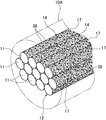
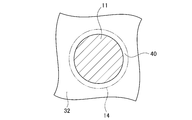
図1において、複合素材10は、複数の連続した炭素繊維11をまとめた炭素繊維束12を含む。各炭素繊維11の表面には、それぞれ構造体14が形成されており、構造体14の表面にサイジング剤(図示省略)が付着している。 [First Embodiment]
[Composite material]
In FIG. 1, the
重量比Rが0.0005以上であれば、炭素繊維強化成形体としたときに、上記のような構造体14による大きな拘束効果、複合領域での機械的エネルギーの大きな吸収効果を確実に得ることができ、CNT由来の特性が向上される。重量比Rが0.01以下であれば、構造体14へのマトリックス樹脂の樹脂含浸が確実になされる。また、重量比Rが0.001以上0.01以下であることがより好ましい。重量比Rが0.001以上であれば、ほぼ全ての炭素繊維11間にて構造体14(CNT17)がより確実に機能する。重量比Rが0.01以下であれば、構造体14へのマトリックス樹脂の樹脂含浸が確実になされ、また炭素繊維強化成形体におけるマトリックス樹脂の比率が低い場合であっても構造体14がより確実に機能する。さらに、重量比Rが0.001以上0.005以下であることがさらに好ましい。0.005以下であれば炭素繊維強化成形体におけるマトリックス樹脂の比率が低い場合であっても構造体14がより確実に機能する。 Moreover, the uniformity of adhesion of the
When the weight ratio R is 0.0005 or more, when a carbon fiber reinforced molded body is obtained, a large restraining effect by the

炭素繊維束12の各炭素繊維11のそれぞれにCNT17を付着させて構造体14を形成するには、CNT17が単離分散したCNT単離分散液(以下、単に分散液と称する)中に炭素繊維束12を浸漬し、分散液に機械的エネルギーを付与する。単離分散とは、CNT17が1本ずつ物理的に分離して絡み合わずに分散媒中に分散している状態をいい、2以上のCNT17が束状に集合した集合物の割合が10%以下である状態をさす。ここで集合物の割合が10%以上であると、分散媒中でのCNT17の凝集が促進され、CNT17の炭素繊維11に対する付着が阻害される。 [Production method of composite material]
In order to form the
分散液28は、例えば長尺のCNT(以下、材料CNTと称する)を分散媒に加え、ホモジナイザーや、せん断力、超音波分散機などにより、材料CNTを切断して所望とする長さのCNT17とするとともに、CNT17の分散の均一化を図ることで調製される。 [Dispersion]
The
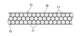
図4において、プリプレグ31は、炭素繊維束12の構造体14が形成された炭素繊維11と、この炭素繊維束12に含浸された未硬化のマトリックス樹脂32とで構成される。プリプレグ31は、開繊された複合素材10にマトリックス樹脂32を含浸し、厚み方向に炭素繊維11が複数本並んだ帯状に形成される。複合素材10は、炭素繊維束12における炭素繊維11同士の絡み合いが実質的に存在しないものであるので、プリプレグ31を製造する際に、炭素繊維11を均一に拡げやすい。プリプレグ31の各炭素繊維11の繊維軸方向は、いずれも同一方向(図4の紙面垂直方向)に揃っている。プリプレグ31は、幅方向(開繊した方向)に複数の開繊した複合素材10を並べて形成することで、幅広のものとすることができる。 [Prepreg]
In FIG. 4, the
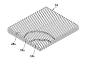
プリプレグ31を加圧しながらマトリックス樹脂32を加熱硬化することで炭素繊維強化成形体が作製される。複数枚のプリプレグ31を積層した積層体を加圧及び加熱することで、積層体を一体化した炭素繊維強化成形体とすることもできる。この場合、積層体における炭素繊維11の繊維軸方向は、プリプレグ31に相当する層ごとに任意の方向とすることができる。図5に示す炭素繊維強化成形体34では、プリプレグ31に相当する複数の層34aにおいて、炭素繊維11の繊維軸方向が上下の層34aで互いに直交するように形成されている。加熱及び加圧する手法は、プレス成形法、オートクレーブ成形法、バッギング成形法、シートワインディング法、フィラメントワインディング法および内圧成形法等を用いることができる。マトリックス樹脂32の体積含有率は、10~40%が好ましく、15~33%がより好ましい。マトリックス樹脂32は、弾性率が2~5GPa程度であることが好ましい。 [Carbon fiber reinforced compact]
A carbon fiber reinforced molded body is produced by heat curing the
第2実施形態の複合素材は、構造体を構成する複数のCNTの一部を炭素繊維の表面に部分的に固定する複数の固定樹脂部を有するものである。以下に詳細を説明する他は、第1実施形態と同様であり、実質的に同じ部材には同一の符号を付して、その詳細な説明を省略する。 [Second Embodiment]
The composite material of the second embodiment has a plurality of fixed resin portions that partially fix a part of the plurality of CNTs constituting the structure to the surface of the carbon fiber. Except for the details described below, the second embodiment is the same as the first embodiment, and substantially the same members are denoted by the same reference numerals, and detailed description thereof is omitted.
図6において、複合素材10Aは、複数の連続した炭素繊維11をまとめた炭素繊維束12を含む。各炭素繊維11の表面には、それぞれ構造体14が形成されている。各構造体14は、複数のカーボンナノチューブ(以下、CNTと称する)17で構成される。また、複合素材10Aは、構造体14を構成する複数のCNT17の一部を炭素繊維11の表面に部分的に固定する複数の固定樹脂部38が設けられている。複合素材10Aは、典型的には炭素繊維強化成形体に用いられる。 [Composite material]
In FIG. 6, the
上記複合素材10Aの製造工程は、構造体14の表面に第1サイジング剤を付着させる第1サイジング処理に代えて、固定樹脂部38を形成する第2サイジング処理を行なう他は、第1実施形態と同じである。すなわち、炭素繊維束12は、分散液28(図2参照)中から引き出された後に乾燥された炭素繊維束12に対して第2サイジング処理を行うことで、固定樹脂部38を形成する。第2サイジング処理は、固定樹脂部38となる材料やその形態に応じた処理とすることができる。 [Production method of composite material]
The manufacturing process of the
この例におけるプリプレグ31(図5参照)は、炭素繊維束12の構造体14及び固定樹脂部18が形成された炭素繊維11と、この炭素繊維束12に含浸された未硬化のマトリックス樹脂19とで構成される。また、このプリプレグ31を加圧しながらマトリックス樹脂32を加熱硬化することで炭素繊維強化成形体が作製される。この例におけるプリプレグ31及び炭素繊維強化成形体およびその作製手法は、各炭素繊維11に固定樹脂部38が形成されている他は、第1実施形態のものと同様である。 [Prepreg, carbon fiber reinforced molding]
The prepreg 31 (see FIG. 5) in this example includes a
(均一性の評価)
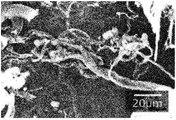
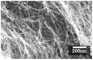
A.SEM観察
第1サイジング処理及び乾燥後の炭素繊維束12の一部を切り出し、第1サイジング剤を除去してから、炭素繊維11を取得した。取得した各炭素繊維11に複数のCNT17が均一に分散して付着していることをSEM観察して確認した。 <Example 1>
(Evaluation of uniformity)
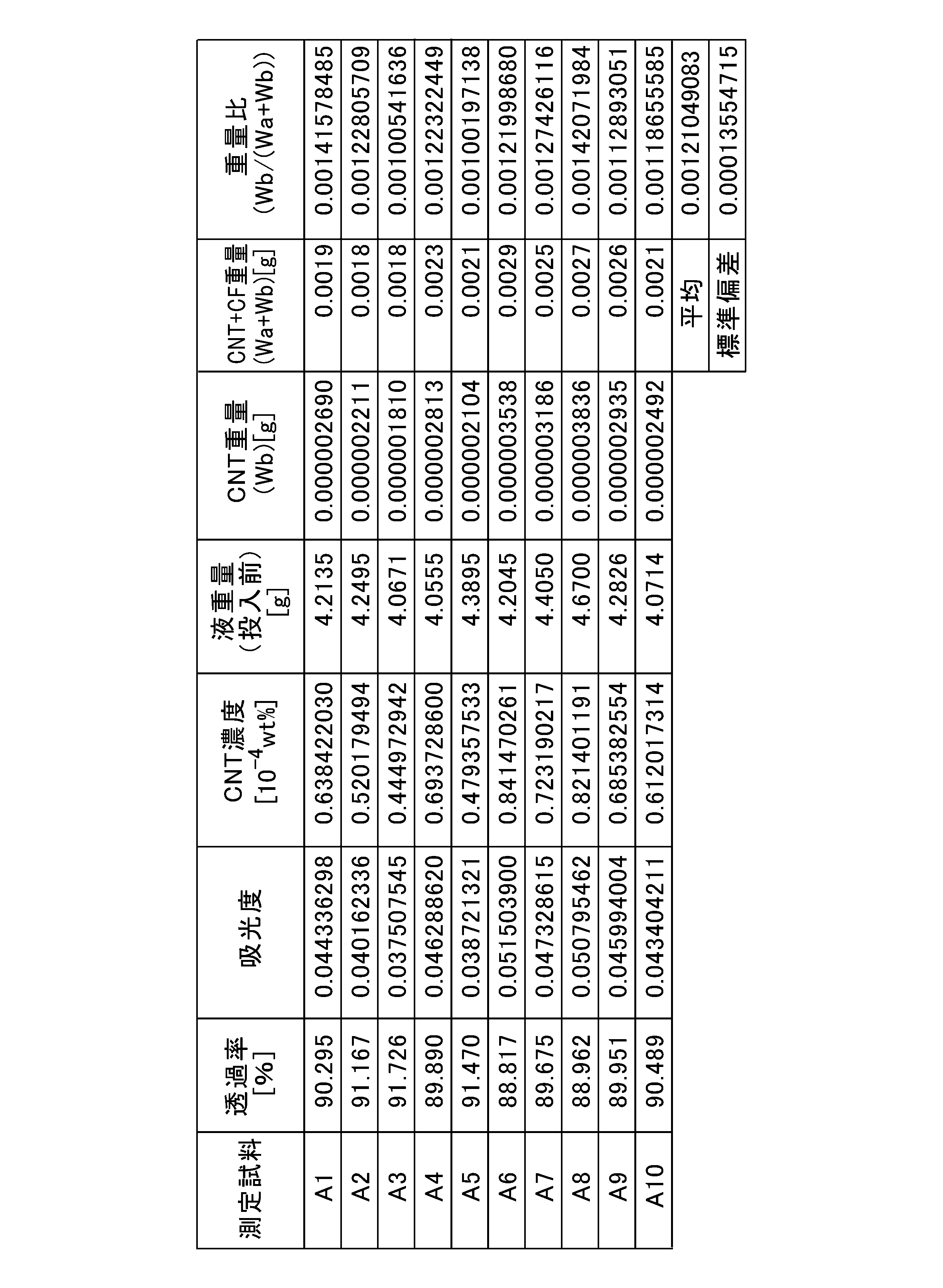
A. SEM Observation A part of the
次に重量比Rによる均一性の評価を行った。第1サイジング処理後の炭素繊維束12の長さ1mの評価範囲をほぼ均等に網羅するように10ヶ所の測定部位を設定した。10ヶ所の測定部位は、評価範囲の両端とその間の8カ所とし、各測定部位のそれぞれについて3mm(約2mg)程度にそれぞれ炭素繊維束12(12000本の炭素繊維11)を切り出して測定試料A1~A10とした。測定試料A1~A10のそれぞれについて下記のようにして重量比Rを求めた。 B. Weight ratio Next, the uniformity by weight ratio R was evaluated. Ten measurement sites were set so that the evaluation range of 1 m in length of the
(2)測定試料を投入する前の測定液の重量と測定試料を含む測定液の重量との差分を計測し、これを測定試料の重量、すなわち炭素繊維11のCF重量Waとその炭素繊維11に付着しているCNT17のCNT重量Wbとの和(Wa+Wb)とする。
(3)測定試料を含む測定液に超音波振動を与えて、炭素繊維11からそれに付着しているCNT17を完全に分離し、CNT17を測定液中に分散する。
(4)吸光光度計を用いて,CNT17が分散している測定液の吸光度(透過率)を測定する。吸光光度計による測定結果と、予め作成しておいた検量線とから測定液中のCNT17の濃度(以下、CNT濃度という)を求める。CNT濃度をC、測定液の重量をW1、この測定液に含まれるCNT17の重量W2としたときに、「C=W2/(W1+W2)」で与えられる重量パーセント濃度である。
(5)得られたこのCNT濃度と測定試料を投入する前の測定液の重量とから測定液中のCNT17の重量(Wb)を求める。
(6)(2)で求めたCF重量WaとCNT重量Wbの和(Wa+Wb)と、CNT17の重量(Wb)とから、重量比R(=Wb/(Wa+Wb))を算出する。 (1) A measurement sample is put into a liquid (hereinafter referred to as a measurement liquid) serving as a dispersion medium for the
(2) The difference between the weight of the measurement liquid before the measurement sample is introduced and the weight of the measurement liquid including the measurement sample is measured, and this is measured, that is, the CF weight Wa of the
(3) Ultrasonic vibration is applied to the measurement liquid containing the measurement sample to completely separate the
(4) The absorbance (transmittance) of the measurement liquid in which the
(5) The weight (Wb) of the
(6) The weight ratio R (= Wb / (Wa + Wb)) is calculated from the sum (Wa + Wb) of the CF weight Wa and the CNT weight Wb obtained in (2) and the weight (Wb) of the
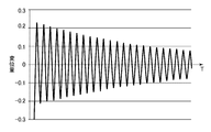
(振動減衰特性の評価)
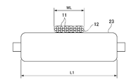
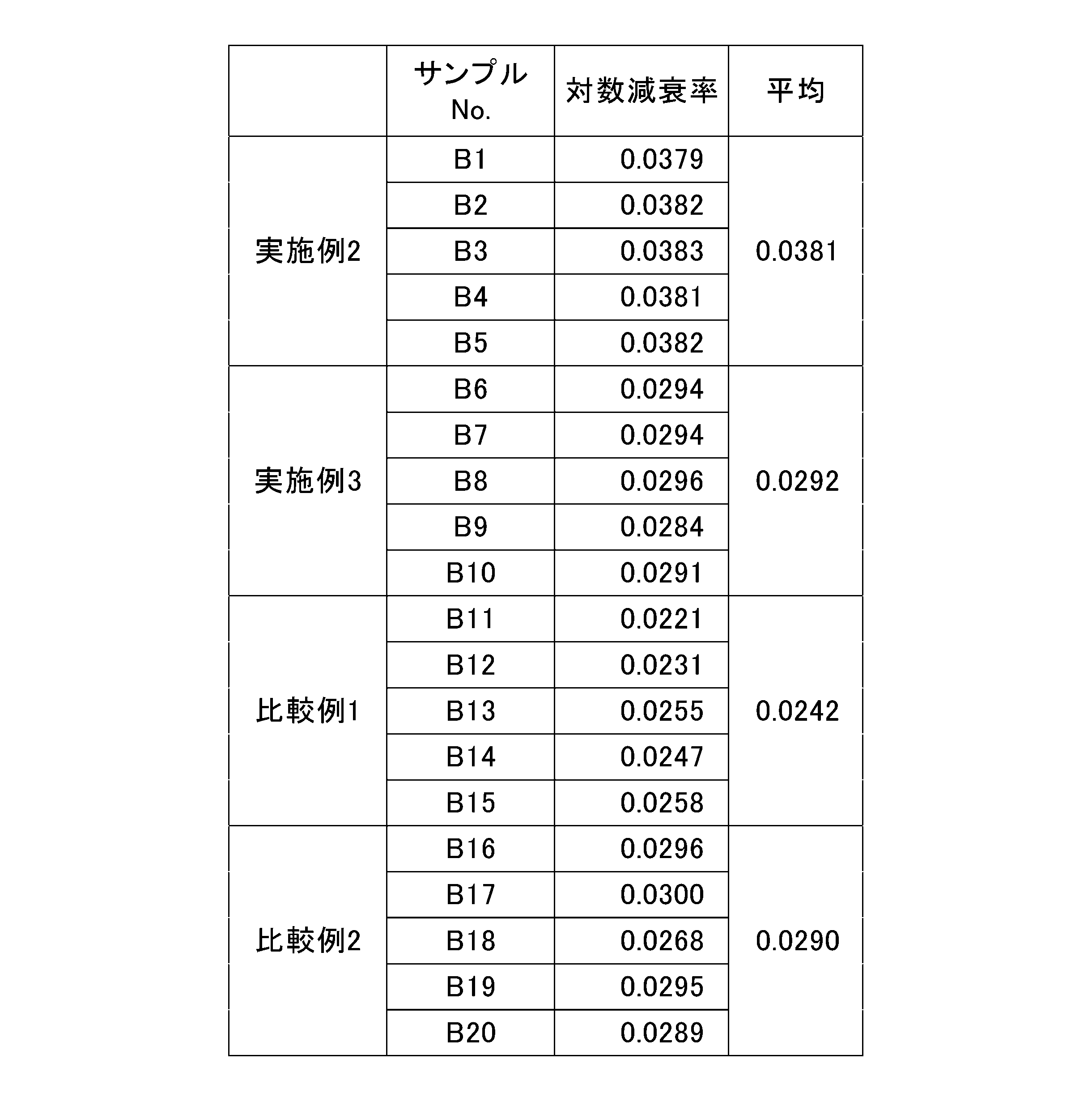
実施例2として、図17に示すように、炭素繊維強化成形体として板状の試験片41を作製し振動減衰特性(制振性)を評価した。実施例2の試験片41は、幅D41を15mm、長さL41を200mm厚さt41を1.8mmとした。試験片41の作製では、200mm×15mmの長方形に切断した16枚のプリプレグ31を積層し、加圧しながら145℃で1時間加熱してマトリックス樹脂32を硬化させた。各プリプレグ31は、長手方向が炭素繊維11の繊維軸方向と一致するように切断した。したがって、試験片41は、その長手方向に全ての炭素繊維11の繊維軸方向(図中矢印A方向)が一致している。 <Examples 2 and 3>
(Evaluation of vibration damping characteristics)
As Example 2, as shown in FIG. 17, a plate-
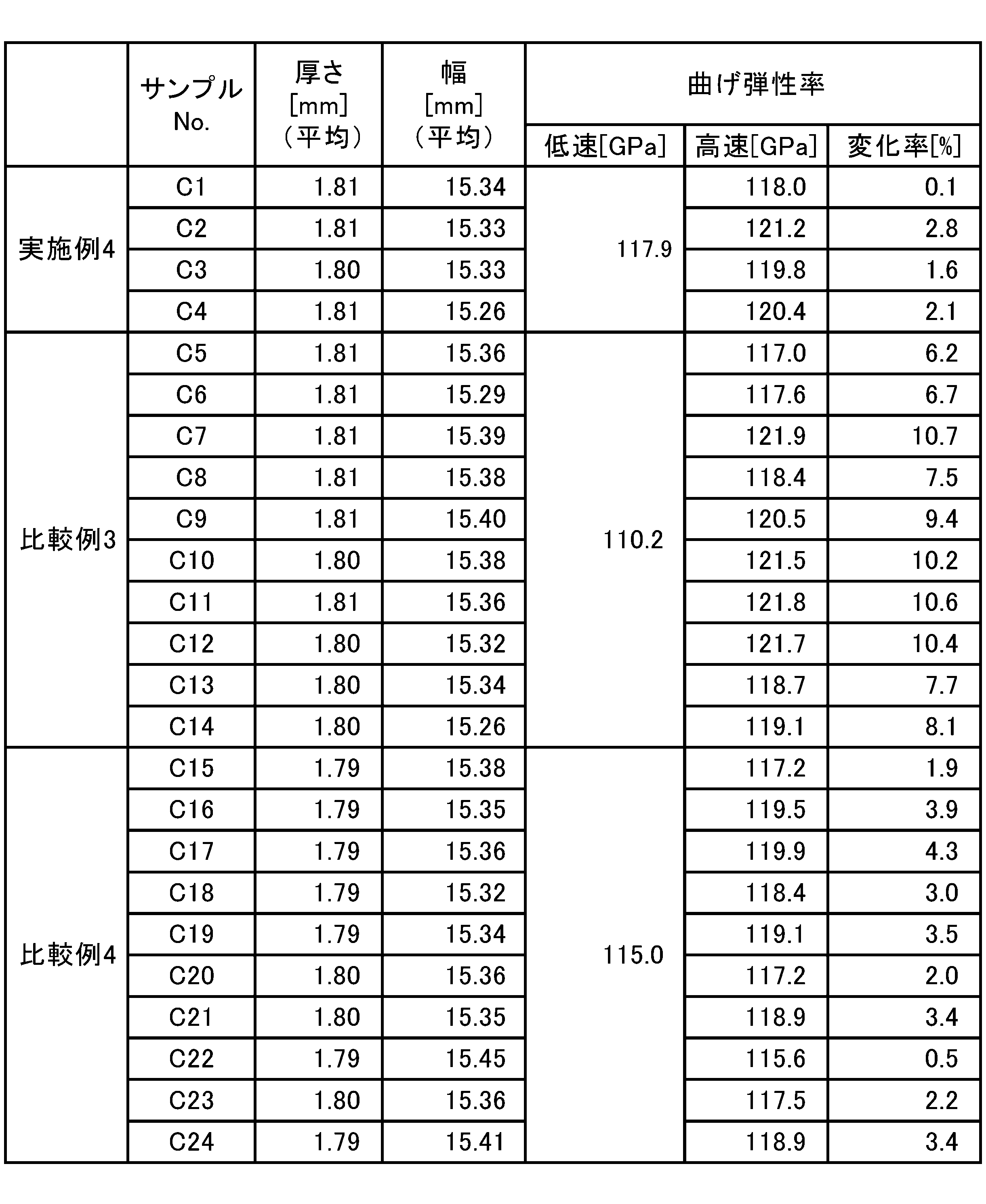
(曲げ弾性率の変化特性)
実施例4では、図21に示すように、炭素繊維強化成形体として板状の試験片51を作製して曲げ弾性率の変化特性を評価した。試験片51は、長さL51を100mm、幅D51を15mm、厚さt51を1.8mmとした。試験片51の作製では、100mm×15mmの長方形に切断した16枚のプリプレグ31を積層し、加圧しながら145℃で1時間加熱してマトリックス樹脂32を硬化させた。試験片51は、実施例2の試験片41と同様に、その長手方向に全ての炭素繊維11の繊維軸方向(図中矢印A方向)が一致している。 <Example 4>
(Change characteristics of flexural modulus)
In Example 4, as shown in FIG. 21, a plate-shaped

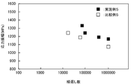
(疲労特性の評価)
実施例5として、図22に示すように、炭素繊維強化成形体として板状の試験片61を作製し、3点曲げ疲労試験を行って曲げ疲労特性を評価した。実施例5の試験片61は、幅D61を15mm、長さL61を20mm以上、厚さt61を1.8mmとした。試験片61の作製では、長方形(L61×D61)に切断した16枚のプリプレグ31を積層し、加圧しながら145℃で1時間加熱してマトリックス樹脂32を硬化させた。各プリプレグ31は、長手方向が炭素繊維11の繊維軸方向と一致するように切断した。したがって、試験片61は、その長手方向に全ての炭素繊維11の繊維軸方向(図中矢印A方向)が一致している。 <Example 5>
(Evaluation of fatigue characteristics)
As Example 5, as shown in FIG. 22, a plate-
複合素材10Aからプリプレグ31を経て、実施例6で用いる炭素繊維強化成形体(試験片)を作製し、試験片に90°曲げ試験を行なった。 <Examples 6 and 7>
A carbon fiber reinforced molded body (test piece) used in Example 6 was produced from the

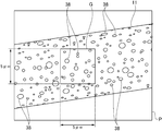
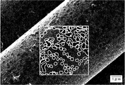
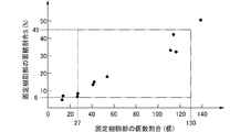
固定樹脂部38の個数割合Nと面積割合Sとの傾向を調べるため、炭素繊維11に対する固定樹脂部38の付着量が異なる11種類の試料を作製した。炭素繊維束及びそれに対する処理条件等は、サイジング液の希釈率以外は、実施例6の場合と同様とした。得られた各試料について、5μm四方の観察枠を設定して、個数割合Nと面積割合Sを調べた。 [Example 8]
In order to examine the tendency between the number ratio N and the area ratio S of the fixed
11 炭素繊維
12 炭素繊維束
14 構造体
17 カーボンナノチューブ
34 炭素繊維強化成形体
38 固定樹脂部 DESCRIPTION OF
Claims (18)
- 炭素繊維と、
複数のカーボンナノチューブで構成され、前記カーボンナノチューブ同士が直接接触したネットワーク構造を形成するとともに、前記炭素繊維の表面に付着する前記カーボンナノチューブが前記炭素繊維の表面に直接付着した構造体と
を備え、
前記カーボンナノチューブは、屈曲部を有する曲がった形状である
ことを特徴とする複合素材。 Carbon fiber,
A structure composed of a plurality of carbon nanotubes, forming a network structure in which the carbon nanotubes are in direct contact with each other, and a structure in which the carbon nanotubes attached to the surface of the carbon fibers are directly attached to the surface of the carbon fibers, and
The carbon nanotube has a bent shape having a bent portion. - 一部の前記カーボンナノチューブを部分的に前記炭素繊維の表面に固定する複数の固定樹脂部を備え、
平面視した前記構造体の表面における、前記構造体の表面を覆う前記複数の固定樹脂部の面積の割合が6%以上45%以下の範囲内である
ことを特徴とする請求項1に記載の複合素材。 A plurality of fixing resin parts for partially fixing the carbon nanotubes to the surface of the carbon fiber;
The ratio of the area of the plurality of fixed resin portions covering the surface of the structure body in the surface of the structure body in plan view is within a range of 6% or more and 45% or less. Composite material. - 平面視した前記構造体の表面における、5μm四方当たりの前記固定樹脂部の個数が27個以上130個以下の範囲内であることを特徴とする請求項2に記載の複合素材。 3. The composite material according to claim 2, wherein the number of the fixed resin portions per 5 μm square on the surface of the structure in plan view is in a range of 27 to 130. 5.
- 前記構造体は、厚さが10nm以上300nm以下の範囲内であることを特徴とする請求項1ないし3のいずれか1項に記載の複合素材。 The composite material according to any one of claims 1 to 3, wherein the structure has a thickness in a range of 10 nm to 300 nm.
- 前記カーボンナノチューブは、長さが0.1μm以上10μm以下の範囲内であり、かつ直径が1nm以上15nm以下の範囲内であることを特徴とする請求項1ないし4のいずれか1項に記載の複合素材。 5. The carbon nanotube according to claim 1, wherein the carbon nanotube has a length in a range of 0.1 μm to 10 μm and a diameter in a range of 1 nm to 15 nm. Composite material.
- 前記炭素繊維における当該炭素繊維の重量に対する当該炭素繊維に付着している前記カーボンナノチューブの重量の比である重量比が0.0005以上0.01以下の範囲内であることを特徴とする請求項1ないし5のいずれか1項に記載の複合素材。 The weight ratio, which is the ratio of the weight of the carbon nanotube attached to the carbon fiber to the weight of the carbon fiber in the carbon fiber, is in the range of 0.0005 or more and 0.01 or less. The composite material according to any one of 1 to 5.
- 前記炭素繊維の長さ1mの範囲における前記重量比の標準偏差が0.0005以下の範囲内であることを特徴とする請求項6に記載の複合素材。 The composite material according to claim 6, wherein a standard deviation of the weight ratio in the range of 1 m in length of the carbon fiber is within a range of 0.0005 or less.
- 複数の連続した前記炭素繊維により炭素繊維束が形成され、
前記炭素繊維束の前記炭素繊維のそれぞれに前記構造体が形成されていることを特徴とする請求項1ないし7のいずれか1項に記載の複合素材。 A carbon fiber bundle is formed by a plurality of continuous carbon fibers,
The composite material according to claim 1, wherein the structure is formed on each of the carbon fibers of the carbon fiber bundle. - 前記複数の炭素繊維にそれぞれ形成された前記構造体は、互いに独立した構造であり、一の前記炭素繊維の前記構造体と他の前記炭素繊維の前記構造体は、同じ前記カーボンナノチューブを共有しないことを特徴とする請求項8に記載の複合素材。 The structures formed in the plurality of carbon fibers are independent structures, and the structure of one carbon fiber and the structure of another carbon fiber do not share the same carbon nanotube. The composite material according to claim 8.
- 屈曲部を有する曲がった形状の複数のカーボンナノチューブが分散された分散液に超音波振動を印加する超音波工程と、
前記超音波振動が印加されている前記分散液に複数の連続した炭素繊維を有する炭素繊維束を開繊して浸漬し、前記炭素繊維に前記複数のカーボンナノチューブを付着させて、前記炭素繊維のそれぞれの表面に構造体を形成する付着工程と
を有することを特徴とする複合素材の製造方法。 An ultrasonic step of applying ultrasonic vibration to a dispersion in which a plurality of bent carbon nanotubes having a bent portion are dispersed;
A carbon fiber bundle having a plurality of continuous carbon fibers is opened and immersed in the dispersion liquid to which the ultrasonic vibration is applied, and the plurality of carbon nanotubes are attached to the carbon fibers, so that the carbon fibers A method of manufacturing a composite material, comprising: an attaching step of forming a structure on each surface. - 前記付着工程の後に、開繊された前記炭素繊維束を未硬化の樹脂を分散媒に分散させた処理液に接触させてから、前記炭素繊維束から前記分散媒を蒸発させるとともに前記樹脂を硬化させて、前記構造体の一部の前記カーボンナノチューブを部分的に前記炭素繊維の表面に固定する複数の固定樹脂部を形成する固定樹脂部形成工程
を有することを特徴とする請求項10に記載の複合素材の製造方法。 After the adhesion step, the opened carbon fiber bundle is brought into contact with a treatment liquid in which an uncured resin is dispersed in a dispersion medium, and then the dispersion medium is evaporated from the carbon fiber bundle and the resin is cured. 11. A fixing resin portion forming step of forming a plurality of fixing resin portions for partially fixing the carbon nanotubes of a part of the structure to the surface of the carbon fiber. Of manufacturing composite materials. - 前記超音波工程は、前記超音波振動の周波数が40kHz以上950kHz以下の範囲内であることを特徴とする請求項10または11に記載の複合素材の製造方法。 The method for producing a composite material according to claim 10 or 11, wherein, in the ultrasonic step, a frequency of the ultrasonic vibration is in a range of 40 kHz to 950 kHz.
- 前記超音波振動の周波数をfs、前記カーボンナノチューブを付着させる前記炭素繊維束の部分が前記分散液に浸漬されている浸漬時間をTs秒としたときに、「Ts≧65000/fs」を満たすことを特徴とする請求項10ないし12のいずれか1項に記載の複合素材の製造方法。 “Ts ≧ 65000 / fs” is satisfied when the frequency of the ultrasonic vibration is fs and the immersion time in which the portion of the carbon fiber bundle to which the carbon nanotubes are attached is immersed in the dispersion is Ts seconds. The method for producing a composite material according to any one of claims 10 to 12, wherein:
- 請求項8または9に記載の複合素材と、
前記複合素材に含浸した状態のマトリックス樹脂と
を含むことを特徴とするプリプレグ。 The composite material according to claim 8 or 9,
A prepreg comprising: a matrix resin impregnated in the composite material. - 請求項8または9に記載の複合素材と、
前記複合素材に含浸した状態で硬化しているマトリックス樹脂と
を含むことを特徴とする炭素繊維強化成形体。 The composite material according to claim 8 or 9,
And a matrix resin cured in a state of being impregnated in the composite material. - 請求項8または9に記載の複合素材と、
前記複合素材に含浸した状態で硬化しているマトリックス樹脂と
を含み、
長さ100mm、幅15mm、厚さ1.8mmの板状で幅方向が前記炭素繊維の繊維軸方向に一致する試験片として、JIS K 7074:1988に準拠した3点曲げ試験で5mm/分の試験速度で測定される曲げ弾性率に対して、同一の条件で試験速度を1000mm/秒にして測定される曲げ弾性率の増加率が2%以下であることを特徴とする炭素繊維強化成形体。 The composite material according to claim 8 or 9,
A matrix resin cured in a state of being impregnated in the composite material,
As a test piece having a length of 100 mm, a width of 15 mm, and a thickness of 1.8 mm and having a width direction coinciding with the fiber axis direction of the carbon fiber, it is 5 mm / min in a three-point bending test according to JIS K 7074: 1988. A carbon fiber reinforced molded article characterized in that an increase rate of a flexural modulus measured at a test speed of 1000 mm / sec under the same conditions is 2% or less with respect to a flexural modulus measured at a test speed. . - 請求項8または9に記載の複合素材と、
前記複合素材に含浸した状態で硬化しているマトリックス樹脂と
を含み、
長さ200mm、幅15mm、厚さ1.8mmの板状で長手方向が前記炭素繊維の繊維軸方向に一致する試験片として、長手方向の一端の長さ50mmの範囲を挟持して水平に固定された前記試験片の他端を押し下げてから解放した後に測定される前記試験片の他端の変位量から得られる振幅の対数減衰率が0.029%以上であることを特徴とする炭素繊維強化成形体。 The composite material according to claim 8 or 9,
A matrix resin cured in a state of being impregnated in the composite material,
As a test piece having a plate shape of 200 mm in length, 15 mm in width, and 1.8 mm in thickness and whose longitudinal direction coincides with the fiber axis direction of the carbon fiber, it is fixed horizontally with a range of 50 mm length at one end in the longitudinal direction. A logarithmic decay rate of amplitude obtained from the amount of displacement of the other end of the test piece measured after the other end of the test piece is pushed down and released is a carbon fiber, characterized in that it is 0.029% or more. Reinforced molded body. - 請求項8または9に記載の複合素材と、
前記複合素材に含浸した状態で硬化しているマトリックス樹脂と
を含み、
長さ20mm以上、幅15mm、厚さ1.8mmの板状で幅方向が前記炭素繊維の繊維軸方向に一致する試験片として、前記試験片の長手方向に20mmだけ離して配置された一対の支点で前記試験片を下側から支持した状態で、上方からの前記試験片の押圧と押圧の解除とを繰り返す片振りの3点曲げ疲労試験を行ったときに、応力振幅が1100MPa以上1300MPa以下の範囲内であるときの押圧時の荷重が0となるまでの押圧の繰り返し数が92000回以上1000000回以下の範囲内であることを特徴とする炭素繊維強化成形体。 The composite material according to claim 8 or 9,
A matrix resin cured in a state of being impregnated in the composite material,
As a test piece having a length of 20 mm or more, a width of 15 mm, and a thickness of 1.8 mm and having a width direction coincident with the fiber axis direction of the carbon fiber, a pair of 20 mm apart in the longitudinal direction of the test piece is disposed. In a state where the test piece is supported from the lower side by a fulcrum, when a three-point bending fatigue test is performed in which the test piece is repeatedly pressed and released from above, a stress amplitude is 1100 MPa to 1300 MPa. The carbon fiber reinforced molded article is characterized in that the number of times of pressing until the load during pressing when it is in the range of 0 is in the range of 92,000 times or more and 1000000 times or less.
Priority Applications (6)
| Application Number | Priority Date | Filing Date | Title |
|---|---|---|---|
| EP19820455.4A EP3819424A4 (en) | 2018-06-11 | 2019-06-10 | Composite material, prepreg, carbon fiber reinforced molded product, and method for producing composite material |
| CN201980052734.5A CN112567091B (en) | 2018-06-11 | 2019-06-10 | Composite material, prepreg, carbon fiber-reinforced molded body, and method for producing composite material |
| JP2020525563A JPWO2019240094A1 (en) | 2018-06-11 | 2019-06-10 | Manufacturing method of composite material, prepreg, carbon fiber reinforced molded product and composite material |
| KR1020217000368A KR20210019059A (en) | 2018-06-11 | 2019-06-10 | Composite material, prepreg, carbon fiber reinforced molded body and method of manufacturing composite material |
| US15/734,624 US20210230386A1 (en) | 2018-06-11 | 2019-06-10 | Composite material, prepreg, carbon fiber reinforced molded product, and method for producing composite material |
| TW108120078A TWI833763B (en) | 2018-06-11 | 2019-06-11 | Composite material, prepreg, carbon fiber reinforced molded article and method of manufacturing composite material |
Applications Claiming Priority (6)
| Application Number | Priority Date | Filing Date | Title |
|---|---|---|---|
| JP2018-111473 | 2018-06-11 | ||
| JP2018111473 | 2018-06-11 | ||
| JP2018-178137 | 2018-09-21 | ||
| JP2018178137 | 2018-09-21 | ||
| JP2019059510 | 2019-03-26 | ||
| JP2019-059510 | 2019-03-26 |
Publications (1)
| Publication Number | Publication Date |
|---|---|
| WO2019240094A1 true WO2019240094A1 (en) | 2019-12-19 |
Family
ID=68841984
Family Applications (1)
| Application Number | Title | Priority Date | Filing Date |
|---|---|---|---|
| PCT/JP2019/022976 WO2019240094A1 (en) | 2018-06-11 | 2019-06-10 | Composite material, prepreg, carbon fiber reinforced molded product, and method for producing composite material |
Country Status (6)
| Country | Link |
|---|---|
| US (1) | US20210230386A1 (en) |
| EP (1) | EP3819424A4 (en) |
| JP (1) | JPWO2019240094A1 (en) |
| KR (1) | KR20210019059A (en) |
| CN (1) | CN112567091B (en) |
| WO (1) | WO2019240094A1 (en) |
Cited By (3)
| Publication number | Priority date | Publication date | Assignee | Title |
|---|---|---|---|---|
| WO2022114217A1 (en) * | 2020-11-30 | 2022-06-02 | ニッタ株式会社 | Composite material, method for producing same, and method for producing reinforcing fiber base material |
| EP4063558A4 (en) * | 2019-11-20 | 2023-12-06 | Nitta Corporation | Composite material, carbon fiber-reinforced molded body, and method for producing composite material |
| EP4063559A4 (en) * | 2019-11-20 | 2024-01-24 | Nitta Corp | Composite material and method for producing same |
Families Citing this family (1)
| Publication number | Priority date | Publication date | Assignee | Title |
|---|---|---|---|---|
| CN109054296B (en) * | 2018-07-04 | 2020-12-04 | 法尔胜泓昇集团有限公司 | High-strength carbon fiber composite reinforcement material with resin ribs on surface and preparation method thereof |
Citations (7)
| Publication number | Priority date | Publication date | Assignee | Title |
|---|---|---|---|---|
| JP2007126311A (en) | 2005-11-01 | 2007-05-24 | Sonac Kk | Method for producing carbon fiber and catalyst substrate |
| JP2008201626A (en) * | 2007-02-20 | 2008-09-04 | Toray Ind Inc | Carbon nanotube assembly and its manufacturing method |
| JP2013076198A (en) | 2011-09-13 | 2013-04-25 | Nitta Ind Corp | Cnt/carbon fiber composite material, fiber-reinforced molded article using the composite material and method for producing composite material |
| JP2016084547A (en) * | 2014-10-23 | 2016-05-19 | ニッタ株式会社 | Composite raw material and reinforced fiber |
| JP2016190969A (en) * | 2015-03-31 | 2016-11-10 | ニッタ株式会社 | Carbon fiber-reinforced molded article |
| JP2016194165A (en) * | 2015-03-31 | 2016-11-17 | ニッタ株式会社 | Method for producing composite stock and composite stock |
| WO2019065535A1 (en) * | 2017-09-27 | 2019-04-04 | ニッタ株式会社 | Composite material, prepreg, carbon-fiber-reinforced molded body, and method for manufacturing composite material |
Family Cites Families (47)
| Publication number | Priority date | Publication date | Assignee | Title |
|---|---|---|---|---|
| WO2002095097A1 (en) * | 2001-05-21 | 2002-11-28 | Trustees Of Boston College, The | Varied morphology carbon nanotubes and methods for their manufacture |
| JP3735651B2 (en) * | 2002-10-08 | 2006-01-18 | 独立行政法人 宇宙航空研究開発機構 | Carbon nanofiber dispersed resin fiber reinforced composite material |
| CA2532190C (en) * | 2003-06-16 | 2012-08-21 | William Marsh Rice University | Sidewall functionalization of carbon nanotubes with hydroxyl-terminated moieties |
| US8187703B2 (en) * | 2003-06-16 | 2012-05-29 | William Marsh Rice University | Fiber-reinforced polymer composites containing functionalized carbon nanotubes |
| US20070207318A1 (en) * | 2004-07-21 | 2007-09-06 | Sungho Jin | Catalytically Grown Mano-Bent Nanostructure and Method for Making the Same |
| JP3850427B2 (en) * | 2005-03-22 | 2006-11-29 | 株式会社物産ナノテク研究所 | Carbon fiber bonded body and composite material using the same |
| JP4233560B2 (en) * | 2005-08-12 | 2009-03-04 | 株式会社Gsiクレオス | Manufacturing method of prepreg |
| EP2022886B1 (en) * | 2006-05-02 | 2013-10-16 | Goodrich Corporation | Methods of making nanoreinforced carbon fiber and aircraft components comprising nanoreinforced carbon fiber |
| US8337979B2 (en) * | 2006-05-19 | 2012-12-25 | Massachusetts Institute Of Technology | Nanostructure-reinforced composite articles and methods |
| CN100591613C (en) * | 2006-08-11 | 2010-02-24 | 清华大学 | Carbon nano-tube composite material and preparation method thereof |
| US8951632B2 (en) * | 2007-01-03 | 2015-02-10 | Applied Nanostructured Solutions, Llc | CNT-infused carbon fiber materials and process therefor |
| CN100567602C (en) * | 2007-10-26 | 2009-12-09 | 哈尔滨工业大学 | Carbon nano-tube connecting carbon fiber multi-scale reinforcing body and preparation method thereof |
| US7867468B1 (en) * | 2008-02-28 | 2011-01-11 | Carbon Solutions, Inc. | Multiscale carbon nanotube-fiber reinforcements for composites |
| US9725314B2 (en) * | 2008-03-03 | 2017-08-08 | Performancy Polymer Solutions, Inc. | Continuous process for the production of carbon nanofiber reinforced continuous fiber preforms and composites made therefrom |
| CN101284423B (en) * | 2008-05-30 | 2010-06-02 | 沈阳航空工业学院 | Preparation method of carbon nano tube/carbon fiber multi-dimension mixing composite material |
| US20110159270A9 (en) * | 2008-06-02 | 2011-06-30 | Texas A & M University System | Carbon nanotube fiber-reinforced polymer composites having improved fatigue durability and methods for production thereof |
| JP2011528056A (en) * | 2008-07-17 | 2011-11-10 | ナノシル エス.エー. | Method for producing reinforced thermosetting polymer composite |
| JP5557992B2 (en) * | 2008-09-02 | 2014-07-23 | 国立大学法人北海道大学 | Conductive fiber, conductive yarn, fiber structure having carbon nanotubes attached thereto, and manufacturing method thereof |
| JP5577356B2 (en) * | 2009-02-17 | 2014-08-20 | アプライド ナノストラクチャード ソリューションズ リミテッド ライアビリティー カンパニー | Composite material composed of carbon nanotubes on the fiber |
| TWI393669B (en) * | 2009-04-10 | 2013-04-21 | Hon Hai Prec Ind Co Ltd | Carbon nanotube composite and method for making the same |
| DE102009036120A1 (en) * | 2009-08-05 | 2011-02-10 | Hexion Specialty Chemicals Gmbh | Coated strength carrier |
| US20110123735A1 (en) * | 2009-11-23 | 2011-05-26 | Applied Nanostructured Solutions, Llc | Cnt-infused fibers in thermoset matrices |
| US20120160966A1 (en) * | 2009-11-23 | 2012-06-28 | Applied Nanostructured Solutions, Llc | Cnt-tailored composite space-based structures |
| WO2011072071A1 (en) * | 2009-12-08 | 2011-06-16 | Applied Nanostructured Solutions, Llc | Cnt-infused fibers in thermoplastic matrices |
| CN101718037B (en) * | 2009-12-10 | 2012-03-28 | 哈尔滨工业大学 | Preparation method of root-like carbon nanotube grafting carbon fiber reinforcement |
| US20130028744A1 (en) * | 2010-01-14 | 2013-01-31 | Pontus Nordin | Aerodynamic surface with improved properties |
| BR112012018244A2 (en) * | 2010-02-02 | 2016-05-03 | Applied Nanostructured Sols | carbon nanotube infused fiber materials containing parallel aligned carbon nanotubes, methods for producing them and composite materials derived therefrom |
| KR101537987B1 (en) * | 2010-08-11 | 2015-07-20 | 보드 오브 리전츠, 더 유니버시티 오브 텍사스 시스템 | Fabrication method of composite carbon nanotube fibers/yarns |
| KR101182380B1 (en) * | 2011-03-15 | 2012-09-12 | 한양대학교 산학협력단 | Hybrid polymer composite fibers comprising graphene and carbon nanotubes |
| US8470946B1 (en) * | 2012-08-20 | 2013-06-25 | The Regents Of The University Of California | Enhanced strength carbon nanotube yarns and sheets using infused and bonded nano-resins |
| CN102924736A (en) * | 2012-10-30 | 2013-02-13 | 天津大学 | Preparation of carbon fiber/ carbon nano tube/ epoxy resin composite material and assisted by freezing and drying |
| US9107292B2 (en) * | 2012-12-04 | 2015-08-11 | Applied Nanostructured Solutions, Llc | Carbon nanostructure-coated fibers of low areal weight and methods for producing the same |
| KR102337052B1 (en) * | 2013-04-24 | 2021-12-07 | 니타 가부시키가이샤 | Composite material and molded article |
| CN103321034A (en) * | 2013-06-29 | 2013-09-25 | 西北工业大学 | Surface modification method of carbon fibre plasma grafted carbon nano-tube |
| CN103409985B (en) * | 2013-08-07 | 2015-04-22 | 常州大学 | Preparation method of carbon nano tube loaded carbon fiber |
| CN104120605B (en) * | 2014-07-16 | 2016-02-10 | 哈尔滨工业大学 | Emulsion pasting agent of a kind of carbon nano-tube modification and its preparation method and application |
| US20160023904A1 (en) * | 2014-07-28 | 2016-01-28 | Massachusetts Institute Of Technology | Strain engineered microstructures |
| CN104327454B (en) * | 2014-10-11 | 2016-07-06 | 沈阳航空航天大学 | A kind of preparation method of CNT/continuous fiber hybrid buildup composite |
| CN104558525B (en) * | 2014-10-11 | 2017-01-11 | 浙江大学 | High-bending strength oxidized carbon nanomaterial/carbon fiber/epoxy resin composite material and preparation method thereof |
| GB201421827D0 (en) * | 2014-12-09 | 2015-01-21 | Short Brothers Plc | Fibre-reinforced components including nanostructures |
| CN106149357B (en) * | 2015-03-27 | 2019-03-22 | 国家电网公司 | A kind of method of carbon fiber surface load carbon nanotube |
| KR101689861B1 (en) * | 2015-05-26 | 2016-12-26 | 한국과학기술연구원 | Nanocarbon composite carbon fiber with low cost and high performance and their preparation method |
| CN104894869A (en) * | 2015-06-05 | 2015-09-09 | 中国科学院山西煤炭化学研究所 | Fast preparation method of carbon fiber reinforcement |
| CN105418969B (en) * | 2015-12-04 | 2017-12-29 | 南昌航空大学 | A kind of preparation method of the carbon nanotube grafting carbon fiber reinforcement based on click chemistry |
| US10920085B2 (en) * | 2016-01-20 | 2021-02-16 | Honda Motor Co., Ltd. | Alteration of carbon fiber surface properties via growing of carbon nanotubes |
| CN106906642A (en) * | 2017-03-28 | 2017-06-30 | 青岛科技大学 | A kind of device that carbon fiber surface modification is carried out by rapid attachment two-phase layer CNT |
| CN107476055B (en) * | 2017-09-07 | 2019-09-13 | 青岛大学 | A kind of method of the directly green grafted carbon nanofiber of carbon fiber surface |
-
2019
- 2019-06-10 KR KR1020217000368A patent/KR20210019059A/en unknown
- 2019-06-10 JP JP2020525563A patent/JPWO2019240094A1/en active Pending
- 2019-06-10 US US15/734,624 patent/US20210230386A1/en active Pending
- 2019-06-10 WO PCT/JP2019/022976 patent/WO2019240094A1/en active Application Filing
- 2019-06-10 EP EP19820455.4A patent/EP3819424A4/en active Pending
- 2019-06-10 CN CN201980052734.5A patent/CN112567091B/en active Active
Patent Citations (7)
| Publication number | Priority date | Publication date | Assignee | Title |
|---|---|---|---|---|
| JP2007126311A (en) | 2005-11-01 | 2007-05-24 | Sonac Kk | Method for producing carbon fiber and catalyst substrate |
| JP2008201626A (en) * | 2007-02-20 | 2008-09-04 | Toray Ind Inc | Carbon nanotube assembly and its manufacturing method |
| JP2013076198A (en) | 2011-09-13 | 2013-04-25 | Nitta Ind Corp | Cnt/carbon fiber composite material, fiber-reinforced molded article using the composite material and method for producing composite material |
| JP2016084547A (en) * | 2014-10-23 | 2016-05-19 | ニッタ株式会社 | Composite raw material and reinforced fiber |
| JP2016190969A (en) * | 2015-03-31 | 2016-11-10 | ニッタ株式会社 | Carbon fiber-reinforced molded article |
| JP2016194165A (en) * | 2015-03-31 | 2016-11-17 | ニッタ株式会社 | Method for producing composite stock and composite stock |
| WO2019065535A1 (en) * | 2017-09-27 | 2019-04-04 | ニッタ株式会社 | Composite material, prepreg, carbon-fiber-reinforced molded body, and method for manufacturing composite material |
Non-Patent Citations (1)
| Title |
|---|
| See also references of EP3819424A4 |
Cited By (4)
| Publication number | Priority date | Publication date | Assignee | Title |
|---|---|---|---|---|
| EP4063558A4 (en) * | 2019-11-20 | 2023-12-06 | Nitta Corporation | Composite material, carbon fiber-reinforced molded body, and method for producing composite material |
| EP4063559A4 (en) * | 2019-11-20 | 2024-01-24 | Nitta Corp | Composite material and method for producing same |
| WO2022114217A1 (en) * | 2020-11-30 | 2022-06-02 | ニッタ株式会社 | Composite material, method for producing same, and method for producing reinforcing fiber base material |
| JP7106040B1 (en) * | 2020-11-30 | 2022-07-25 | ニッタ株式会社 | Composite material, method for producing same, and method for producing reinforcing fiber base material |
Also Published As
| Publication number | Publication date |
|---|---|
| JPWO2019240094A1 (en) | 2021-06-17 |
| CN112567091A (en) | 2021-03-26 |
| US20210230386A1 (en) | 2021-07-29 |
| EP3819424A1 (en) | 2021-05-12 |
| EP3819424A4 (en) | 2022-05-11 |
| TW202000590A (en) | 2020-01-01 |
| CN112567091B (en) | 2023-05-02 |
| KR20210019059A (en) | 2021-02-19 |
Similar Documents
| Publication | Publication Date | Title |
|---|---|---|
| WO2019240094A1 (en) | Composite material, prepreg, carbon fiber reinforced molded product, and method for producing composite material | |
| KR102588148B1 (en) | Methods for manufacturing composite materials, prepregs, carbon fiber reinforced molded bodies and composite materials | |
| Alnefaie et al. | New development of self-damping MWCNT composites | |
| US11820880B2 (en) | Compositions and methods for carbon fiber-metal and other composites | |
| JP7149188B2 (en) | CARBON FIBER REINFORCED MOLDED PRODUCT AND METHOD OF PRODUCING CARBON FIBER REINFORCED MOLDED PRODUCT | |
| Gao et al. | The preparation and properties of novel structural damping composites reinforced by nitrile rubber coated 3‐D braided carbon fibers | |
| JP7106040B1 (en) | Composite material, method for producing same, and method for producing reinforcing fiber base material | |
| TWI833763B (en) | Composite material, prepreg, carbon fiber reinforced molded article and method of manufacturing composite material | |
| WO2021100735A1 (en) | Composite material and production method for same | |
| WO2021100859A1 (en) | Composite material and method for producing same | |
| WO2021100734A1 (en) | Composite material, carbon fiber-reinforced molded body, and method for producing composite material | |
| JP7360786B2 (en) | Composite material manufacturing method | |
| Konada et al. | Effect of surface treatments on damping behaviour of carbon fibre reinforced brake friction material | |
| Hemath et al. | Effect of ferrous, nickel, and tungsten fillers reinforcement on glass fiber reinforced vinyl ester/polyester composites | |
| Rana | Evaluation of Electrical and Mechanical Properties of Carbon-Fiber Composites Using Interleaved Materials |
Legal Events
| Date | Code | Title | Description |
|---|---|---|---|
| 121 | Ep: the epo has been informed by wipo that ep was designated in this application |
Ref document number: 19820455 Country of ref document: EP Kind code of ref document: A1 |
|
| WWE | Wipo information: entry into national phase |
Ref document number: 2020525563 Country of ref document: JP |
|
| NENP | Non-entry into the national phase |
Ref country code: DE |
|
| ENP | Entry into the national phase |
Ref document number: 20217000368 Country of ref document: KR Kind code of ref document: A |
|
| ENP | Entry into the national phase |
Ref document number: 2019820455 Country of ref document: EP Effective date: 20210111 |