WO2019239690A1 - 受信装置、および、受信装置の制御方法 - Google Patents
受信装置、および、受信装置の制御方法 Download PDFInfo
- Publication number
- WO2019239690A1 WO2019239690A1 PCT/JP2019/015056 JP2019015056W WO2019239690A1 WO 2019239690 A1 WO2019239690 A1 WO 2019239690A1 JP 2019015056 W JP2019015056 W JP 2019015056W WO 2019239690 A1 WO2019239690 A1 WO 2019239690A1
- Authority
- WO
- WIPO (PCT)
- Prior art keywords
- physical layer
- layer pipe
- bit string
- information
- value
- Prior art date
- Legal status (The legal status is an assumption and is not a legal conclusion. Google has not performed a legal analysis and makes no representation as to the accuracy of the status listed.)
- Ceased
Links
Images







Classifications
-
- H—ELECTRICITY
- H04—ELECTRIC COMMUNICATION TECHNIQUE
- H04L—TRANSMISSION OF DIGITAL INFORMATION, e.g. TELEGRAPHIC COMMUNICATION
- H04L27/00—Modulated-carrier systems
- H04L27/26—Systems using multi-frequency codes
- H04L27/2601—Multicarrier modulation systems
- H04L27/2647—Arrangements specific to the receiver only
-
- H—ELECTRICITY
- H04—ELECTRIC COMMUNICATION TECHNIQUE
- H04L—TRANSMISSION OF DIGITAL INFORMATION, e.g. TELEGRAPHIC COMMUNICATION
- H04L27/00—Modulated-carrier systems
- H04L27/26—Systems using multi-frequency codes
- H04L27/2601—Multicarrier modulation systems
-
- H—ELECTRICITY
- H04—ELECTRIC COMMUNICATION TECHNIQUE
- H04H—BROADCAST COMMUNICATION
- H04H40/00—Arrangements specially adapted for receiving broadcast information
- H04H40/18—Arrangements characterised by circuits or components specially adapted for receiving
-
- H—ELECTRICITY
- H04—ELECTRIC COMMUNICATION TECHNIQUE
- H04L—TRANSMISSION OF DIGITAL INFORMATION, e.g. TELEGRAPHIC COMMUNICATION
- H04L69/00—Network arrangements, protocols or services independent of the application payload and not provided for in the other groups of this subclass
- H04L69/30—Definitions, standards or architectural aspects of layered protocol stacks
- H04L69/32—Architecture of open systems interconnection [OSI] 7-layer type protocol stacks, e.g. the interfaces between the data link level and the physical level
- H04L69/322—Intralayer communication protocols among peer entities or protocol data unit [PDU] definitions
- H04L69/323—Intralayer communication protocols among peer entities or protocol data unit [PDU] definitions in the physical layer [OSI layer 1]
-
- H—ELECTRICITY
- H04—ELECTRIC COMMUNICATION TECHNIQUE
- H04N—PICTORIAL COMMUNICATION, e.g. TELEVISION
- H04N21/00—Selective content distribution, e.g. interactive television or video on demand [VOD]
- H04N21/40—Client devices specifically adapted for the reception of or interaction with content, e.g. set-top-box [STB]; Operations thereof
- H04N21/43—Processing of content or additional data, e.g. demultiplexing additional data from a digital video stream; Elementary client operations, e.g. monitoring of home network or synchronising decoder's clock; Client middleware
- H04N21/438—Interfacing the downstream path of the transmission network originating from a server, e.g. retrieving encoded video stream packets from an IP network
Definitions
- the present technology relates to a receiving device and a control method of the receiving device. Specifically, the present invention relates to a receiving apparatus that receives terrestrial digital broadcasting and a control method for the receiving apparatus.
- an OFDM (Orthogonal Frequency Division Multiplexing) frame is transmitted and received.
- the OFDM frame includes a preamble and a maximum of 256 subframes, and each subframe includes a packet sequence called PLP (Physical Layer Pipe).
- PLP Physical Layer Pipe
- a receiving device In order to efficiently process an OFDM frame having this configuration, for example, a receiving device has been proposed that includes a control circuit that decodes a preamble and a signal processing unit that decodes a PLP according to the decoding result (for example, a patent) Reference 1).
- the decoding of the preamble and the decoding of the PLP can be performed in parallel by the control circuit and the signal processing unit, so that the processing speed can be increased compared to a configuration in which they are sequentially executed.
- the signal processing unit since the signal processing unit performs processing using the decoding result of the control circuit, it is necessary to arrange a holding unit (such as a buffer) that holds the decoding result between the control circuit and the signal processing unit.
- a holding unit such as a buffer
- the control circuit acquires the identification information of the PLP by decoding and passes it to the signal processing circuit, it is necessary to secure a capacity of 64 ⁇ 6 bits in the holding unit.
- the above-described receiving apparatus has a problem that the size of the holding unit increases according to the decoding result.
- the present technology has been created in view of such a situation, and an object thereof is to reduce the size of a holding unit that holds a decoding result in a receiving device that decodes a preamble.
- the present technology has been made to solve the above-described problems.
- the first aspect of the present technology is to hold a plurality of bits each assigned physical layer pipe identification information as a physical layer pipe presence / absence bit string.
- a receiving unit that receives a physical layer pipe that does not exceed the number of bits of the physical layer pipe presence / absence bit string and the physical layer pipe identification information of each of the predetermined number of physical layer pipes, and the physical layer pipe
- a setting unit that sets a bit value corresponding to the received physical layer pipe identification information in the presence / absence bit string to one of the two values, and sets a value of the non-corresponding bit to the other of the two values, and the one value
- a control method therefor comprising: a decoding processing unit that performs a process of decoding the physical layer pipe corresponding to each bit.
- the receiving unit receives a subframe in which the predetermined number of physical layer pipes are stored and a preamble in which the physical layer pipe identification information is stored, and the physical layer pipe presence / absence bit string. May be the maximum number of physical layer pipes stored in the subframe.
- the holding unit further holds a plurality of bits assigned to the physical layer pipe identification information as an LLS (Low Level Signaling) presence / absence bit string
- the receiving unit The LLS flag of each of the physical layer pipes of the number is further received, and the setting unit binarizes a bit value corresponding to the physical layer pipe identification information of the physical layer pipe including the LLS information in the LLS presence / absence bit string.
- the decoding processing unit sets the LLS information from the physical layer pipe corresponding to the bit of the one value in the LLS presence / absence bit string. You may get it. This brings about the effect
- the holding unit further holds a plurality of bits assigned to the physical layer pipe identification information as a combined presence / absence bit string, and the receiving unit has the predetermined number of physical layer pipes.
- the setting unit further sets the value of the bit corresponding to the physical layer pipe identification information of the physical layer pipe to be combined in the combined presence / absence bit string to one of the binary values, and does not correspond
- the bit value may be set to the other of the two values, and the decoding processing unit may combine the physical layer pipes corresponding to the one value bit in the combination presence / absence bit string. This brings about the effect
- the holding unit further holds a plurality of bits assigned to the physical layer pipe identification information as an extended presence / absence bit string
- the receiving unit relates to LDM (LayeredLayerDivision Multiplexing)
- LDM LayerDivision Multiplexing
- the setting unit sets the bit value corresponding to the physical layer pipe identification information of the extended physical layer pipe in the extended presence / absence bit string to one of the two values, and sets the value of the non-corresponding bit to the value
- the other of the binary values may be set, and the decoding processing unit may perform decoding using LDM based on the extension presence / absence bit string. This brings about the effect that LDM is used.
- an interpretation unit that periodically interprets a preamble including the physical layer pipe identification information may be further provided. As a result, the preamble is interpreted periodically.
- the receiving unit receives a frame conforming to the ATSC (Advanced Television Systems Committee Standards) 3.0 standard, and the frame includes a sub-frame in which the predetermined number of physical layer pipes are stored. It may include a frame and a preamble in which the physical layer pipe identification information is stored. As a result, the physical layer pipe of the ATSC 3.0 standard is decrypted.
- ATSC Advanced Television Systems Committee Standards
- the present technology in a receiving apparatus that decodes a preamble, it is possible to achieve an excellent effect that the size of a buffer that holds a decoding result can be reduced.
- the effects described here are not necessarily limited, and may be any of the effects described in the present disclosure.
- FIG. 7 is a flowchart illustrating an example of an operation of the reception device according to the first embodiment of the present technology. It is a figure which shows an example of the data hold
- FIG. 1 is a block diagram illustrating a configuration example of the receiving device 100 according to the first embodiment of the present technology.
- the receiving apparatus 100 is an apparatus that receives digital terrestrial broadcasting compliant with the ATSC 3.0 standard, and includes an antenna 101, a high speed processing unit 110, and a low speed processing unit 150.
- the antenna 101 receives a radio signal on which an OFDM frame is superimposed.
- the antenna 101 is an example of a receiving unit described in the claims.
- the high-speed processing unit 110 is configured by hardware such as an IC (Integrated Circuit) circuit.
- the high-speed processing unit 110 includes a main signal processing unit 120, an L1 (Layer 1) information acquisition unit 111, an L1 information interpretation unit 112, a setting unit 113, a high-speed control unit 114, and a bit string buffer 130.
- the low speed processing unit 150 is realized by software executed by a CPU (Central Processing Unit) or the like, and includes a low speed control unit 151.
- a CPU Central Processing Unit
- the low speed processing unit 150 includes a low speed control unit 151.
- the main signal processing unit 120 performs processing for buffering the OFDM frame and decoding the payload in the OFDM frame according to the control of the high speed control unit 114 and the low speed control unit 151.
- the main signal processing unit 120 is an example of a decoding processing unit described in the claims.
- the L1 information acquisition unit 111 acquires L1 information from the OFDM frame.
- the L1 information acquisition unit 111 decodes the bootstrap and reads the preamble from the OFDM frame buffered in the main signal processing unit 120.
- L1 information is stored in the preamble, and this L1 information includes L1-Basic information and L1-Detail information.
- the L1 information acquisition unit 111 supplies the read L1 information to the L1 information interpretation unit 112.
- the L1 information interpretation unit 112 interprets L1 information.
- the interpretation of the L1 information is performed every time an OFDM frame is received.
- the interpretation of the L1 information is executed when the stop is detected.
- the L1 information interpretation unit 112 is an example of an interpretation unit described in the claims.
- the L1-Detail information in the L1 information stores information on each of the subframes in the OFDM frame. For example, information such as the use status of MIMO (Multiple-Input and Multiple-Output), the FFT (Fast-Fourier-Transform) size, and the length of the guard interval is stored for each subframe.
- MIMO Multiple-Input and Multiple-Output
- FFT Fast-Fourier-Transform
- PLPID Physical Layer Pipe IDentification information
- LLS flag Physical Layer Pipe IDentification information
- PLP size is stored for each PLP.
- the L1 information interpretation unit 112 supplies each of the PLP individual information in the subframe individual information to the high-speed control unit 114 and the setting unit 113.
- the high speed control unit 114 controls the main signal processing unit 120 based on the PLP individual information.
- the high-speed control unit 114 decodes the PLP individual information, acquires information (such as a PLP size) necessary for decoding the PLP, excluding the PLPID and the LLS flag, and supplies the information to the main signal processing unit 120 to decode the PLP. . Further, the high speed control unit 114 exchanges the execution status between the low speed control unit 151 and the L1 information interpretation unit 112.
- the bit string buffer 130 holds a predetermined bit string. Details of the data structure of the bit string will be described later.
- the bit string buffer 130 is an example of a holding unit described in the claims.
- the setting unit 113 decodes the PLP individual information, acquires the PLPID and the LLS flag, and sets a value to the bit string in the bit string buffer 130 based on them. Details of the setting method will be described later. Further, the setting unit 113 exchanges the execution status with the low speed control unit 151.
- the low speed control unit 151 controls the main signal processing unit 120 based on the bit string in the bit string buffer 130. Details of the control contents will be described later.
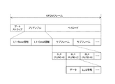
- FIG. 2 is a diagram illustrating an example of a data structure of an OFDM frame according to the first embodiment of the present technology.
- An OFDM frame includes a bootstrap, a preamble, and a payload.
- the bootstrap stores the version, bandwidth, and preamble structure.
- L1-Basic information and L1-Detail information are stored.
- the L1-Basic information stores a pilot signal encoding method and the like. Details of the L1-Detail information will be described later.
- the maximum 256 subframes are stored in the payload.
- a maximum of 64 PLPs are stored in each subframe.
- the PLP can store content data and LLS information.
- LLS information is not necessarily stored in all PLPs.
- an LLS flag indicating whether or not the corresponding PLP includes LLS information is stored.
- the LLS information is information of layers higher than the physical layer (transport layer, application layer, etc.) and includes, for example, channel information indicating a channel corresponding to the stream.
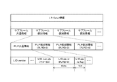
- FIG. 3 is a diagram illustrating an example of a data structure of the L1-Detail information according to the first embodiment of the present technology.
- the L1-Detail information includes subframe common information and a maximum of 256 pieces of subframe individual information.
- Each subframe individual information includes PLP common information and a maximum of 64 pieces of PLP individual information.
- L1D_version In the PLP common information, “L1D_version” and “L1D_num_plp” indicating the number of PLPs in the subframe are stored.
- L1D_plp_id indicating the PLPID
- L1D_plp_lls_flag indicating the LLS flag are stored. 6 bits are assigned to the PLPID, and 1 bit is assigned to the LLS flag.
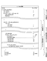
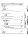
- FIG. 4 is a diagram illustrating an example of the syntax of the L1-Detail information according to the first embodiment of the present technology.
- the syntax is "ATSC Standard: Physical Layer Protocol Doc. A / 322: 2017", Advanced Television Systems Committee, Internet (https://www.atsc.org / standards / atsc-3-0-standards /) ”.
- L1D_version In the L1-Detail information, “L1D_version” and “L1D_num_rf” are stored in order from the top. “L1D_version” is the version of the L1-Detail signaling structure used for the current frame. “L1D_num_rf” is the number of frequencies involved in channel bonding that are not included in the current channel frequency.
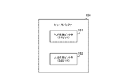
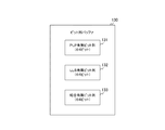
- FIG. 5 is a diagram illustrating an example of data held in the bit string buffer 130 according to the first embodiment of the present technology.
- the bit string buffer 130 holds a PLP presence / absence bit string 131 and an LLS presence / absence bit string 132.
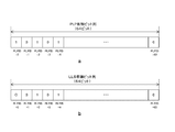
- FIG. 6 is a diagram illustrating an example of a data structure of the PLP presence / absence bit string 131 and the LLS presence / absence bit string 132 according to the first embodiment of the present technology.
- a is a diagram showing an example of the data structure of the PLP presence / absence bit string 131
- b in the figure is a diagram showing an example of the data structure of the LLS presence / absence bit string 132.
- the PLP presence / absence bit string 131 is an array of a plurality of bits to which different PLPIDs are assigned. For example, in the ATSC 3.0 standard, since a maximum of 64 PLPs are stored for each subframe, the size of the PLP presence / absence bit string 131 is 64 bits. A PLPID of “n” is assigned to the nth bit (n is an integer from 0 to 63) of the PLP presence / absence bit string 131. Each bit indicates whether or not a corresponding PLPID PLP exists in the subframe.
- the setting unit 113 decodes the received L1 information and obtains a 6-bit PLPID for each PLP in the subframe. Then, the setting unit 113 sets the bit corresponding to the acquired PLPID to one of the binary values (such as “1”) in the PLP presence / absence bit string 131, and sets the bit that does not correspond to the other binary value (such as “0”). Set. For example, the setting unit 113 performs setting by initializing all bits of the PLP presence / absence bit string 131 to “0” at the start of decoding of the subframe individual information and updating the bit corresponding to the acquired PLPID to “1”.
- the LLS presence / absence bit string 132 is an array of a plurality of bits to which different PLPIDs are assigned. Since a maximum of 64 PLPs are stored for each subframe, the size of the LLS presence / absence bit string 132 is also 64 bits. A PLPID of “n” is assigned to the nth bit of the LLS presence / absence bit string 132. Each bit indicates whether or not LLS information is included in the PLP of the corresponding PLPID.
- the setting unit 113 decodes the received L1 information and obtains a 1-bit LLS flag for each PLP in the subframe. This LLS flag indicates whether or not the corresponding PLP includes LLS information. Then, the setting unit 113 sets the bit corresponding to the PLPID of the PLP including the LLS information in the LLS presence / absence bit string 132 to one of the binary values (logical value “1” or the like), and sets the other bits to the other binary value. (Logical value “0” or the like). For example, the setting unit 113 initializes all the bits of the LLS presence / absence bit string 132 to “0” at the start of decoding of the subframe individual information, and updates the bits corresponding to the PLP including the LLS information to “1”. Do.
- FIG. 7 is a block diagram illustrating a configuration example of the main signal processing unit 120 according to the first embodiment of the present technology.
- the main signal processing unit 120 includes an OFDM frame buffer 121 and a decoding circuit 122.
- the OFDM frame buffer 121 holds an OFDM frame.
- the decoding circuit 122 decodes the PLP in the OFDM frame.
- the low-speed control unit 151 refers to the PLP presence / absence bit string 131 in the bit string buffer 130 and determines whether the bit value is the logical value “1” in order from the first bit. If the logical value is “1”, the low speed control unit 151 transmits a decoding instruction signal to the decoding circuit 122.
- the decoding circuit 122 Each time the decoding circuit 122 receives a decoding instruction signal, the decoding circuit 122 decodes the PLP in the subframe at the physical layer level using information (encoding method, PLP size, etc.) from the high-speed control unit 114.
- the low-speed control unit 151 refers to the LLS presence / absence bit string 132 in the bit string buffer 130 and determines whether the bit value is the logical value “1” in order from the first bit. If the logical value is “1”, the low speed control unit 151 transmits an LLS acquisition instruction signal to the decoding circuit 122.
- the decoding circuit 122 When the decoding circuit 122 receives the LLS acquisition instruction signal, the decoding circuit 122 extracts LLS information from layers higher than the physical layer (L2 and L3) in the decoded PLP. For example, when extracting the L2 information, the decoding circuit 122 decodes the L2 header in the decoded data of the PLP, and acquires the structure of the L2 payload. Further, when extracting the L3 information, the decoding circuit 122 decodes the L3 header in the L2 payload to obtain the structure of the L3 payload. The decoding circuit 122 outputs the acquired LLS information to the outside.
- L2 and L3 physical layer
- a comparative example is assumed in which the setting unit 113 is not arranged and the high-speed control unit 114 holds 7 bits indicating the PLPID and the LLS flag in the buffer.
- the maximum number of PLPs per subframe is 64, it is necessary to secure a capacity of 64 ⁇ 7 bits in the buffer.
- the setting unit 113 sets the PLP presence / absence bit string 131 and the LLS presence / absence bit string 132, the capacity of the bit string buffer 130 may be reduced to 64 ⁇ 2 bits as compared with the comparative example. it can. Further, the communication amount of the interface between the high speed processing unit 110 and the low speed processing unit 150 can be reduced.
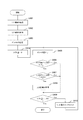
- FIG. 8 is a flowchart illustrating an example of the operation of the reception device 100 according to the first embodiment of the present technology. This operation is started, for example, when an application for receiving an OFDM frame is executed.
- the receiving apparatus 100 acquires the L1 information (step S901) and interprets the L1 information (step S902).
- the setting unit 113 in the receiving apparatus 100 sets values of the PLP presence / absence bit string and the LLS presence / absence bit string based on the PLPID and the LLS flag (step S903).
- the low speed control unit 151 in the receiving apparatus 100 initializes a variable indicating the shift amount to “0” (step S904). Then, the low-speed control unit 151 reads out the bit at the position shifted by the shift amount from the first bit of the PLP presence / absence bit string and the LLS presence / absence bit string (step S905). The low speed controller 151 determines whether or not the bit at the shift position of the PLP presence / absence bit string is a logical value “1” (step S906).
- step S906 If the bit at the shift position is the logical value “1” (step S906: Yes), the low speed control unit 151 determines whether the bit at the shift position in the LLS presence / absence bit string is the logical value “1” (step S906). S907).
- step S907 When the bit of the shift position is the logical value “1” (step S907: Yes), the low speed control unit 151 instructs the main signal processing unit 120 to acquire LLS information, and the main signal processing unit 120 LLS information is acquired from (step S908). The low speed control unit 151 determines whether or not the shift amount is “63” (step S909).
- step S909 is also performed when the bit at the shift position of the PLP presence / absence bit string is not the logical value “1” (step S906: No), or when the bit at the shift position of the LLS presence / absence bit string is not the logical value “1” (step S907: No). Is executed.
- step S909: Yes the receiving apparatus 100 performs the same process on the remaining subframes, and ends the OFDM frame reception process.
- step S909 No
- the low speed control unit 151 increments the shift amount and repeats step S905 and subsequent steps.
- the bit string buffer 130 holds the PLP presence / absence bit string in which the PILID is assigned to each bit, and the setting unit 113 corresponds to the PLPID received in the PLP presence / absence bit string. Set the bit to be "1". For this reason, when the PLPID of the received PLP is held as it is, the PLPID size is required for each PLP, whereas the PLP presence / absence bit string requires only 1 bit for each PLP, and the buffer size can be reduced. it can.
- the receiving apparatus 100 decodes each PLP without combining the PLPs.
- the use efficiency of the frequency band may not be utilized to the maximum extent. is there.
- the receiving apparatus according to the second embodiment is different from the first embodiment in that PLPs belonging to different frequency bands (in other words, channels) are combined.
- FIG. 9 is a diagram illustrating an example of data held in the bit string buffer 130 according to the second embodiment of the present technology.
- the bit string buffer 130 of the second embodiment further holds a combined presence / absence bit string 133.
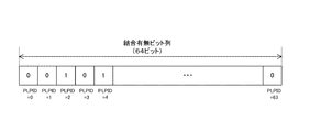
- FIG. 10 is a diagram illustrating an example of a data structure of the combined presence / absence bit string 133 according to the second embodiment of the present technology.
- the combined presence / absence bit string 133 is an array of a plurality of bits assigned different PLPIDs. For example, in the ATSC 3.0 standard, since a maximum of 64 PLPs are stored for each subframe, the size of the combined presence / absence bit string 133 is 64 bits. A PLPID of “n” is assigned to the nth bit of the combined presence / absence bit string 133. Each bit indicates whether the PLP of the corresponding PLPID is combined with another PLP.
- the setting unit 113 decodes the received L1 information and acquires information related to PLP coupling for each PLP in the subframe. Then, the setting unit 113 sets the bit corresponding to the PLPID of the PLP to be combined in one of the binary values (such as “1”) in the combined presence / absence bit string 133, and sets the bit that does not correspond to the other binary value (such as “0”). ).
- the low-speed control unit 151 refers to the combined presence / absence bit string 133 and determines whether the bit value is the logical value “1” in order from the first bit. If the logical value is “1”, the low speed control unit 151 supplies the combination instruction signal to the decoding circuit 122.
- the decoding circuit 122 combines a plurality of PLPs into one code word according to the combination instruction signal, and decodes the code word using information (encoding method, PLP size, etc.) from the high speed control unit 114. Thereby, the decoding circuit 122 can decode more codewords than the case where it does not combine.
- FIG. 11 is a diagram for explaining a PLP coupling relationship according to the second embodiment of the present technology.
- PLPs belonging to different frequency bands can be combined. For example, a PLP with a PLPID “1” in the frequency band RF1 and a PLP with a PLPID “10” in the frequency band RF2 can be combined.
- FIG. 12 is a diagram illustrating an example of a storage location of information related to PLP coupling relationships according to the second embodiment of the present technology.
- This field stores 3-bit information related to PLP coupling. For example, when the corresponding PLP is not combined with the PLP of another channel, “0” is set in the field of “L1D_plp_num_channel_bonded”. On the other hand, when combined, a value of “1” or more is set in the field.
- the bit string buffer 130 holds both the LLS presence / absence bit string 132 and the combined presence / absence bit string 133, but the present invention is not limited to this configuration. For example, when it is not necessary to acquire LLS information, the LLS presence / absence bit string 132 may not be held.
- the receiving apparatus 100 combines and decodes PLPs of different channels, and thus can make maximum use of the frequency band usage efficiency.
- the receiving apparatus 100 does not use LDM, but transmission efficiency is expected to be improved by LDM.
- the receiving apparatus according to the third embodiment is different from the second embodiment in that LDM is used.
- FIG. 13 is a diagram illustrating an example of data held in the bit string buffer 130 according to the third embodiment of the present technology.
- the bit string buffer 130 according to the third embodiment further holds an extension presence / absence bit string 134.
- FIG. 14 is a diagram illustrating an example of a data structure of the extension presence / absence bit string 134 according to the third embodiment of the present technology.
- the extension presence / absence bit string 134 is an array of a plurality of bits to which different PLPIDs are assigned. For example, in the ATSC 3.0 standard, since a maximum of 64 PLPs are stored for each subframe, the size of the extension presence / absence bit string 134 is 64 bits.
- the nth bit of the extension presence / absence bit string 134 is assigned with a PLPID of “n”. Each bit indicates whether the PLP of the corresponding PLPID is an extended PLP or a core PLP.
- PLPs in a subframe are classified into core PLPs and extended PLPs.
- the physical layer is divided and multiplexed into a core layer and an enhancement layer.
- the core PLP belongs to the core layer, and the enhanced PLP belongs to the enhancement layer.
- the enhancement layer does not exist.
- the core PLP is associated with one or more extended PLPs, and the extended PLP corresponding to the core PLP belongs to one time interleave group. That is, the core PLP and the extended PLP are collectively interleaved by the time interleaver on the transmission side and transmitted. As a result, the transmission efficiency is expected to be improved as compared with the case where the LDM is not used.
- the setting unit 113 decodes the received L1 information and acquires information on the LDM for each PLP in the subframe. Then, the setting unit 113 sets the bit corresponding to the PLPID of the extended PLP in one of the binary values (such as “1”) in the extended presence / absence bit string 134, and sets the bit that does not correspond to the other binary value (such as “0”). Set to.
- the low speed control unit 151 refers to the extension presence / absence bit string 134 and determines whether or not the bit value is the logical value “1” in order from the first bit. If the logical value is “1”, the low speed control unit 151 supplies the extension designation signal to the decoding circuit 122.
- the decoding circuit 122 uses the LDM in accordance with the extension designation signal and deinterleaves the core PLP and the extension PLP together.
- FIG. 15 is a diagram illustrating a usage example of the LDM in the third embodiment of the present technology.
- a PLP with a PLPID of “0” is a core PLP belonging to the core layer.
- the PLP with the PLP ID “2” is an enhancement layer belonging to the enhancement layer.
- FIG. 16 is a diagram illustrating an example of a storage location of information related to the LDM according to the third embodiment of the present technology.
- This field stores 2-bit information related to the LDM. For example, when the corresponding PLP is a core PLP belonging to the core layer, “0” is set in the field of “L1D_plp_layer”. On the other hand, in the case of an extended PLP belonging to the extension layer, a value of “1” or more is set in the field of “L1D_plp_layer”.
- the field of “L1D_plp_layer” is 2 bits, it is necessary to secure a capacity of 64 ⁇ 2 bits when the 2 bits are held in the bit string buffer 130 as they are for each PLP.
- the setting unit 113 according to the third embodiment sets the extension presence / absence bit string 134, the capacity for holding information on the LDM can be reduced to 64 bits. Further, the communication amount of the interface between the high speed processing unit 110 and the low speed processing unit 150 can be reduced.
- the receiving apparatus 100 holds the LLS presence / absence bit string 132, the combined presence / absence bit string 133, and the extension presence / absence bit string 134 in the bit string buffer 130, but is not limited to this configuration. For example, when it is not necessary to acquire LLS information, the LLS presence / absence bit string 132 may not be held. Further, when there is no PLP to be coupled, a configuration in which the coupled presence / absence bit string 133 is not retained may be employed.
- the receiving apparatus uses the LDM, the transmission efficiency is expected to be improved as compared with the case where the LDM is not used.
- the receiving apparatus 100 when the output of the PLP is stopped, the receiving apparatus 100 starts interpretation of the L1 information when the stop is detected. In this configuration, the receiving apparatus 100 returns from the stop of the output of the PLP. There is a risk that the time until will be longer.
- the receiving apparatus 100 according to the fourth embodiment is different from the first embodiment in that the time to return is shortened by periodically interpreting the L1 information.
- FIG. 17 is a timing chart illustrating an example of the operation of the reception device 100 according to the fourth and first embodiments of the present technology.
- a in the same figure is a timing chart which shows an example of operation
- B in the figure is a timing chart showing an example of the operation of the receiving apparatus 100 in the first embodiment.
- the L1 information interpretation unit 112 periodically interprets the L1 information in the preamble. For example, interpretation of L1 information is started at timings T0, T2, and T5.
- main signal processing unit 120 outputs, for example, PLP over a period up to timing T1 after timing T0, and the output is interrupted for some reason at timing T1.
- the detection of the output stop takes a certain time. For example, it is assumed that the output stop is detected at the timing T3 after the timing T2 when the interpretation of the L1 information is completed. Since the interpretation of the L1 information has been completed, the main signal processing unit 120 can immediately resume decoding and return at timing T4.
- the L1 information interpretation unit 112 of the first embodiment starts interpretation of the L1 information when detecting a stop at timing T3, and the main signal processing unit 120 resumes decoding at timing T4 when the interpretation is completed. Then, it can return at timing T5.
- the time to return is shortened in cases such as when the interpretation of the L1 information has been completed when detecting the stoppage of PLP output. can do.
- the configuration of the second embodiment or the third embodiment can be applied.
- the receiving apparatus 100 interprets the L1 information periodically, and thus shortens the time from when the output of the PLP is stopped to when it returns. be able to.
- the processing procedure described in the above embodiment may be regarded as a method having a series of these procedures, and a program for causing a computer to execute these series of procedures or a recording medium for storing the program. You may catch it.
- a recording medium for example, a CD (Compact Disc), an MD (MiniDisc), a DVD (Digital Versatile Disc), a memory card, a Blu-ray disc (Blu-ray (registered trademark) Disc), or the like can be used.
- this technique can also take the following structures.
- a holding unit that holds a plurality of bits each assigned physical layer pipe identification information as a physical layer pipe presence / absence bit string;
- a receiving unit that receives a predetermined number of physical layer pipes that do not exceed the number of bits of the physical layer pipe presence / absence bit string and the physical layer pipe identification information of each of the predetermined number of physical layer pipes;
- a setting unit that sets a value of a bit corresponding to the received physical layer pipe identification information in the physical layer pipe presence / absence bit string to one of two values, and sets a value of a bit that does not correspond to the other of the two values;
- a decoding processing unit that performs a process of decoding the physical layer pipe corresponding to the bit of the one value.
- the receiving unit receives a subframe in which the predetermined number of physical layer pipes are stored and a preamble in which the physical layer pipe identification information is stored, The receiving device according to (1), wherein the number of bits of the physical layer pipe presence / absence bit string is a maximum number of the physical layer pipes stored in the subframe.
- the holding unit further holds a plurality of bits assigned to the physical layer pipe identification information as LLS (Low Level Signaling) presence / absence bit strings,
- the receiving unit further receives an LLS flag of each of the predetermined number of physical layer pipes;
- the setting unit sets a value of a bit corresponding to the physical layer pipe identification information of the physical layer pipe including LLS information in the LLS presence / absence bit string to one of binary values, and sets a value of a bit not corresponding to the binary values Set to the other of
- the receiving apparatus according to (1) or (2), wherein the decoding processing unit acquires LLS information from the physical layer pipe corresponding to the bit of the one value in the LLS presence / absence bit string.
- the holding unit further holds a plurality of bits each assigned with the physical layer pipe identification information as a combined presence / absence bit string,
- the receiving unit further receives information related to coupling of the predetermined number of physical layer pipes;
- the setting unit sets a value of a bit corresponding to the physical layer pipe identification information of the physical layer pipe to be combined in the combined presence / absence bit string to one of two values, and sets a value of a bit not corresponding to the other of the two values Set to The reception apparatus according to any one of (1) to (3), wherein the decoding processing unit combines the physical layer pipes corresponding to the one value bit in the combination presence / absence bit string.
- the holding unit further holds a plurality of bits assigned to the physical layer pipe identification information as an extended presence / absence bit string
- the receiver further receives information on LDM (Layered Division Multiplexing)
- the setting unit sets a value of a bit corresponding to the physical layer pipe identification information of the extended physical layer pipe in the extended presence / absence bit string to one of two values, and sets a value of a bit not corresponding to the other of the two values
- the receiving apparatus according to any one of (1) to (4), wherein the decoding processing unit performs decoding using LDM based on the extension presence / absence bit string.
- the receiving apparatus according to any one of (1) to (5), further including an interpreter that periodically interprets a preamble including the physical layer pipe identification information.
- the receiving unit receives a frame compliant with ATSC (Advanced Television Systems Committee standards) 3.0 standard, The receiving device according to any one of (1) to (6), wherein the frame includes a subframe in which the predetermined number of physical layer pipes are stored and a preamble in which the physical layer pipe identification information is stored.
- ATSC Advanced Television Systems Committee standards
Landscapes
- Engineering & Computer Science (AREA)
- Signal Processing (AREA)
- Computer Networks & Wireless Communication (AREA)
- Computer Security & Cryptography (AREA)
- Multimedia (AREA)
- Two-Way Televisions, Distribution Of Moving Picture Or The Like (AREA)
- Communication Control (AREA)
Abstract
プリアンブルをデコードする受信装置において、デコード結果を保持するバッファのサイズを削減する。 保持部は、物理層パイプ識別情報がそれぞれに割り当てられた複数のビットを物理層パイプ有無ビット列として保持する。受信部は、物理層パイプ有無ビット列のビット数を越えない所定数の物理層パイプと所定数の物理層パイプのそれぞれの前記物理層パイプ識別情報とを受信する。設定部は、物理層パイプ有無ビット列のうち受信された物理層パイプ識別情報に対応するビットの値を2値の一方に設定し、対応しないビットの値を2値の他方に設定する。復号処理部は、一方の値のビットに対応する前記物理層パイプを復号する処理を行う。
Description
本技術は、受信装置、および、受信装置の制御方法に関する。詳しくは、地上波デジタル放送を受信する受信装置、および、受信装置の制御方法に関する。
近年、ATSC(Advanced Television Systems Committee standards)3.0規格を用いた次世代の地上波デジタル放送を受信するための受信装置の開発や研究が進められている。このATSC3.0規格では、OFDM(Orthogonal Frequency Division Multiplexing)フレームが送受信される。このOFDMフレームは、プリアンブルと最大256個のサブフレームとを含み、サブフレームのそれぞれはPLP(Physical Layer Pipe)と呼ばれるパケット系列を含む。1つのサブフレームには、最大で64個のPLPを格納することができ、格納したPLPのそれぞれの識別情報やデータサイズなどが、プリアンブル内に格納される。この構成のOFDMフレームを効率的に処理するために、例えば、プリアンブルをデコードする制御回路と、そのデコード結果に従ってPLPを復号する信号処理部とを設けた受信装置が提案されている(例えば、特許文献1参照。)。
上述の従来技術では、プリアンブルのデコードとPLPの復号とを制御回路および信号処理部が並列に実行することができるため、それらを順に実行する構成と比較して処理速度を速くすることができる。しかしながら、信号処理部は、制御回路のデコード結果を用いて処理を行うため、制御回路と信号処理部との間に、そのデコード結果を保持する保持部(バッファなど)を配置する必要がある。そして、デコード結果を詳細な内容にするほど、デコード結果のデータサイズが大きくなり、大きなバッファサイズを要する。例えば、サブフレーム内のPLPは、最大で64(=26)個であるため、その識別情報には、6ビットが割り当てられる。このため、制御回路が、デコードによりPLPの識別情報を取得して信号処理回路に渡す際には、保持部において64×6ビットの容量を確保する必要がある。このように、上述の受信装置では、デコード結果に応じて保持部のサイズが大きくなってしまうという問題がある。
本技術はこのような状況に鑑みて生み出されたものであり、プリアンブルをデコードする受信装置において、デコード結果を保持する保持部のサイズを削減することを目的とする。
本技術は、上述の問題点を解消するためになされたものであり、その第1の側面は、物理層パイプ識別情報がそれぞれに割り当てられた複数のビットを物理層パイプ有無ビット列として保持する保持部と、上記物理層パイプ有無ビット列のビット数を越えない所定数の物理層パイプと上記所定数の物理層パイプのそれぞれの上記物理層パイプ識別情報とを受信する受信部と、上記物理層パイプ有無ビット列のうち上記受信された物理層パイプ識別情報に対応するビットの値を2値の一方に設定し、対応しないビットの値を上記2値の他方に設定する設定部と、上記一方の値のビットに対応する上記物理層パイプを復号する処理を行う復号処理部とを具備する受信装置、および、その制御方法である。これにより、受信した物理層パイプ識別情報をそのまま保持する場合は物理層パイプごとに物理層パイプ識別情報のサイズが必要であったのに対し、物理層パイプごとに1ビットのサイズで済み、保持部のサイズが削減されるという作用をもたらす。
また、この第1の側面において、上記受信部は、上記所定数の物理層パイプが格納されたサブフレームと上記物理層パイプ識別情報が格納されたプリアンブルとを受信し、上記物理層パイプ有無ビット列のビット数は、上記サブフレームに格納される上記物理層パイプの最大数であってもよい。これにより、物理層パイプの最大数に該当するビット数の物理層パイプ有無ビット列における一方の値のビットに対応する物理層パイプが復号されるという作用をもたらす。
また、この第1の側面において、上記保持部は、上記物理層パイプ識別情報がそれぞれに割り当てられた複数のビットをLLS(Low Level Signaling)有無ビット列としてさらに保持し、上記受信部は、上記所定数の物理層パイプのそれぞれのLLSフラグをさらに受信し、上記設定部は、上記LLS有無ビット列のうちLLS情報を含む上記物理層パイプの上記物理層パイプ識別情報に対応するビットの値を2値の一方に設定し、対応しないビットの値を上記2値の他方に設定し、上記復号処理部は、上記LLS有無ビット列内の上記一方の値のビットに対応する上記物理層パイプからLLS情報を取得してもよい。これにより、LLS情報が取得されるという作用をもたらす。
また、この第1の側面において、上記保持部は、上記物理層パイプ識別情報がそれぞれに割り当てられた複数のビットを結合有無ビット列としてさらに保持し、上記受信部は、上記所定数の物理層パイプの結合に関する情報をさらに受信し、上記設定部は、上記結合有無ビット列のうち結合する上記物理層パイプの上記物理層パイプ識別情報に対応するビットの値を2値の一方に設定し、対応しないビットの値を上記2値の他方に設定し、上記復号処理部は、上記結合有無ビット列内の上記一方の値のビットに対応する上記物理層パイプを結合してもよい。これにより、物理層パイプが結合されるという作用をもたらす。
また、この第1の側面において、上記保持部は、上記物理層パイプ識別情報がそれぞれに割り当てられた複数のビットを拡張有無ビット列としてさらに保持し、上記受信部は、LDM(Layered Division Multiplexing)に関する情報をさらに受信し、上記設定部は、上記拡張有無ビット列のうち拡張物理層パイプの上記物理層パイプ識別情報に対応するビットの値を2値の一方に設定し、対応しないビットの値を上記2値の他方に設定し、上記復号処理部は、上記拡張有無ビット列に基づいてLDMを使用して復号してもよい。これにより、LDMが使用されるという作用をもたらす。
また、この第1の側面において、上記物理層パイプ識別情報を含むプリアンブルを定期的に解釈する解釈部をさらに具備してもよい。これにより、プリアンブルが定期的に解釈されるという作用をもたらす。
また、この第1の側面において、上記受信部は、ATSC(Advanced Television Systems Committee standards)3.0規格に準拠したフレームを受信し、上記フレームは、上記所定数の物理層パイプが格納されたサブフレームと上記物理層パイプ識別情報が格納されたプリアンブルとを含むものであってもよい。これにより、ATSC3.0規格の物理層パイプが復号されるという作用をもたらす。
本技術によれば、プリアンブルをデコードする受信装置において、デコード結果を保持するバッファのサイズを削減することができるという優れた効果を奏し得る。なお、ここに記載された効果は必ずしも限定されるものではなく、本開示中に記載されたいずれかの効果であってもよい。
以下、本技術を実施するための形態(以下、実施の形態と称する)について説明する。説明は以下の順序により行う。
1.第1の実施の形態(ビット列に基づいてPLPを復号する例)
2.第2の実施の形態(ビット列に基づいてPLPを結合して復号する例)
3.第3の実施の形態(ビット列に基づいてLDMを使用しつつ、PLPを復号する例)
4.第4の実施の形態(定期的にプリアンブルを解釈し、ビット列に基づいてPLPを復号する例)
1.第1の実施の形態(ビット列に基づいてPLPを復号する例)
2.第2の実施の形態(ビット列に基づいてPLPを結合して復号する例)
3.第3の実施の形態(ビット列に基づいてLDMを使用しつつ、PLPを復号する例)
4.第4の実施の形態(定期的にプリアンブルを解釈し、ビット列に基づいてPLPを復号する例)
<1.第1の実施の形態>
[受信装置の構成例]
図1は、本技術の第1の実施の形態における受信装置100の一構成例を示すブロック図である。この受信装置100は、ATSC3.0規格に準拠した地上波デジタル放送を受信する装置であり、アンテナ101、高速処理部110および低速処理部150を備える。
[受信装置の構成例]
図1は、本技術の第1の実施の形態における受信装置100の一構成例を示すブロック図である。この受信装置100は、ATSC3.0規格に準拠した地上波デジタル放送を受信する装置であり、アンテナ101、高速処理部110および低速処理部150を備える。
アンテナ101は、OFDMフレームが重畳された無線信号を受信するものである。なお、アンテナ101は、特許請求の範囲に記載の受信部の一例である。
高速処理部110は、IC(Integrated Circuit)回路などのハードウェアにより構成される。この高速処理部110は、主信号処理部120、L1(Layer 1)情報取得部111、L1情報解釈部112、設定部113、高速制御部114およびビット列バッファ130を備える。
低速処理部150は、CPU(Central Processing Unit)などが実行するソフトウェアにより実現され、低速制御部151を備える。
主信号処理部120は、OFDMフレームをバッファリングし、高速制御部114および低速制御部151の制御に従ってOFDMフレーム内のペイロードを復号する処理を行うものである。なお、主信号処理部120は、特許請求の範囲に記載の復号処理部の一例である。
L1情報取得部111は、OFDMフレームからL1情報を取得するものである。このL1情報取得部111は、ブートストラップをデコードし、主信号処理部120内にバッファリングされたOFDMフレームからプリアンブルを読み出す。ATSC3.0規格において、プリアンブル内には、L1情報が格納され、このL1情報は、L1-Basic情報とL1-Detail情報とを含む。L1情報取得部111は、読み出したL1情報をL1情報解釈部112に供給する。
L1情報解釈部112は、L1情報を解釈するものである。L1情報の解釈は、OFDMフレームを受信するたびに行われ、PLPの出力が停止した際は、停止の検知時にL1情報の解釈が実行される。なお、L1情報解釈部112は、特許請求の範囲に記載の解釈部の一例である。
ここで、L1情報内のL1-Detail情報は、OFDMフレーム内のサブフレームのそれぞれに関する情報が格納される。例えば、MIMO(Multiple-Input and Multiple-Output)の使用状況、FFT(Fast Fourier Transform)サイズ、および、ガードインターバルの長さなどの情報がサブフレームごとに格納される。これらの情報を以下、「サブフレーム個別情報」と称し、残りの情報を「サブフレーム共通情報」と称する。
また、サブフレーム個別情報内には、サブフレーム内のPLPのそれぞれに関する情報が格納される。例えば、PLPID(Physical Layer Pipe IDentification information)、LLSフラグおよびPLPサイズなどの情報がPLPごとに格納される。これらの情報を以下、「PLP個別情報」と称し、サブフレーム個別情報内の残りの情報を「PLP共通情報」と称する。
L1情報解釈部112は、サブフレーム個別情報をデコードするたびに、そのサブフレーム個別情報内のPLP個別情報のそれぞれを高速制御部114および設定部113に供給する。
高速制御部114は、PLP個別情報に基づいて主信号処理部120を制御するものである。この高速制御部114は、PLP個別情報をデコードし、PLPIDおよびLLSフラグを除く、PLPの復号に必要な情報(PLPサイズなど)を取得し、主信号処理部120に供給してPLPを復号させる。また、高速制御部114は、実行状況を低速制御部151およびL1情報解釈部112との間でやり取りする。
ビット列バッファ130は、所定のビット列を保持するものである。ビット列のデータ構造の詳細については後述する。なお、ビット列バッファ130は、特許請求の範囲に記載の保持部の一例である。
設定部113は、PLP個別情報をデコードし、PLPIDおよびLLSフラグを取得し、それらに基づいてビット列バッファ130内のビット列に値を設定するものである。設定方法の詳細については後述する。また、設定部113は、実行状況を低速制御部151との間でやりとりする。
低速制御部151は、ビット列バッファ130内のビット列に基づいて主信号処理部120を制御するものである。制御内容の詳細については後述する。
図2は、本技術の第1の実施の形態におけるOFDMフレームのデータ構造の一例を示す図である。OFDMフレームは、ブートストラップ、プリアンブルおよびペイロードを含む。
ブートストラップには、バージョン、帯域幅やプリアンブルの構造が格納される。プリアンブルには、L1-Basic情報およびL1-Detail情報が格納される。
L1-Basic情報には、パイロット信号の符号化方法などが格納される。L1-Detail情報の詳細については後述する。
ペイロードには、最大で256個のサブフレームが格納される。また、サブフレームのそれぞれには、最大で64個のPLPが格納される。また、PLPには、コンテンツのデータやLLS情報を格納することができる。ただし、LLS情報は、全てのPLPに格納されるとは限らない。L1-Detail情報内には、対応するPLPがLLS情報を含むか否かを示すLLSフラグが格納される。
LLS情報は、物理層よりも上位の層(トランスポート層やアプリケーション層など)の情報であり、例えば、ストリームに対応するチャネルを示すチャネル情報を含む。
図3は、本技術の第1の実施の形態におけるL1-Detail情報のデータ構造の一例を示す図である。L1-Detail情報は、サブフレーム共通情報と、最大256個のサブフレーム個別情報とを含む。
また、サブフレーム個別情報のそれぞれは、PLP共通情報と、最大64個のPLP個別情報とを含む。
PLP共通情報には、「L1D_version」や、サブフレーム内のPLP数を示す「L1D_num_plp」が格納される。PLP個別情報には、PLPIDを示す「L1D_plp_id」や、LLSフラグを示す「L1D_plp_lls_flag」が格納される。PLPIDには6ビットが割り当てられ、LLSフラグには1ビットが割り当てられる。
図4は、本技術の第1の実施の形態におけるL1-Detail情報の構文の一例を示す図である。この構文は、「ATSC Standard:Physical Layer Protocol Doc. A/322:2017"、Advanced Television Systems Committee、インターネット(https://www.atsc.org
/standards/atsc-3-0-standards/)」に記載されている。
/standards/atsc-3-0-standards/)」に記載されている。
L1-Detail情報には、先頭から順に、「L1D_version」や、「L1D_num_rf」が格納される。「L1D_version」は、現在フレームに関して使用されるL1-Detailシグナリング構造のバージョンである。「L1D_num_rf」は、現在のチャネルの周波数に含まれない、チャネルボンディングに関与する周波数の数である。
また、「for (i=0 .. L1B_num_subframes) {・・・}」は、波括弧内のデータが、サブフレームの個数(最大256個)の分だけ格納されることを意味する。このfor構文の外部の部分がサブフレーム共通情報に該当する。また、そのfor構文の波括弧内のデータは、サブフレーム個別情報に該当する。
サブフレーム個別情報内において、「for (j=0 .. L1D_num_plp) {・・・}」は、波括弧内のデータが、PLPの個数(最大64個)の分だけ格納されることを意味する。このfor構文の直前までがPLP共通情報に該当する。また、そのfor構文の波括弧内のデータは、PLP個別情報に該当する。
PLP個別情報内の「L1D_plp_id」フィールドの6ビットは、PLPIDを表し、「L1D_plp_lls_flag」フィールドの1ビットは、LLSフラグを表す。点線301に示す、これらの7ビットが設定部113によりPLPごとに読み出される。
図5は、本技術の第1の実施の形態におけるビット列バッファ130に保持されるデータの一例を示す図である。ビット列バッファ130には、PLP有無ビット列131およびLLS有無ビット列132が保持される。
図6は、本技術の第1の実施の形態におけるPLP有無ビット列131およびLLS有無ビット列132のデータ構造の一例を示す図である。同図におけるaは、PLP有無ビット列131のデータ構造の一例を示す図であり、同図におけるbは、LLS有無ビット列132のデータ構造の一例を示す図である。
PLP有無ビット列131は、互いに異なるPLPIDが割り当てられた複数のビットを配列したものである。例えば、ATSC3.0規格では、サブフレームごとに最大64個のPLPが格納されるため、PLP有無ビット列131のサイズは64ビットである。PLP有無ビット列131のn(nは0乃至63の整数)ビット目には、「n」のPLPIDが割り当てられる。それぞれのビットは、対応するPLPIDのPLPがサブフレーム内に存在するか否かを示す。
設定部113は、受信されたL1情報をデコードしてサブフレーム内のPLPごとに6ビットのPLPIDを取得する。そして、設定部113は、PLP有無ビット列131において、取得したPLPIDに対応するビットを2値の一方(「1」など)に設定し、対応しないビットを2値の他方(「0」など)に設定する。例えば、設定部113は、サブフレーム個別情報のデコード開始時にPLP有無ビット列131の全ビットを「0」に初期化し、取得したPLPIDに対応するビットを「1」に更新することにより設定を行う。
また、LLS有無ビット列132は、互いに異なるPLPIDが割り当てられた複数のビットを配列したものである。サブフレームごとに最大64個のPLPが格納されるため、LLS有無ビット列132のサイズも64ビットである。LLS有無ビット列132のnビット目には、「n」のPLPIDが割り当てられる。それぞれのビットは、対応するPLPIDのPLPにLLS情報が含まれるか否かを示す。
設定部113は、受信されたL1情報をデコードしてサブフレーム内のPLPごとに1ビットのLLSフラグを取得する。このLLSフラグは、対応するPLPがLLS情報を含むか否かを示す。そして、設定部113は、LLS有無ビット列132において、LLS情報を含むPLPのPLPIDに対応するビットを2値の一方(論理値「1」など)に設定し、それ以外のビットを2値の他方(論理値「0」など)に設定する。例えば、設定部113は、サブフレーム個別情報のデコード開始時にLLS有無ビット列132の全ビットを「0」に初期化し、LLS情報を含むPLPに対応するビットを「1」に更新することにより設定を行う。
[主信号処理部の構成例]
図7は、本技術の第1の実施の形態における主信号処理部120の一構成例を示すブロック図である。この主信号処理部120は、OFDMフレームバッファ121および復号回路122を備える。
図7は、本技術の第1の実施の形態における主信号処理部120の一構成例を示すブロック図である。この主信号処理部120は、OFDMフレームバッファ121および復号回路122を備える。
OFDMフレームバッファ121は、OFDMフレームを保持するものである。復号回路122は、OFDMフレーム内のPLPを復号するものである。
低速制御部151は、ビット列バッファ130内のPLP有無ビット列131を参照し、先頭ビットから順にビットの値が論理値「1」であるか否かを判断する。論理値「1」であれば、低速制御部151は、復号指示信号を復号回路122に送信する。
復号回路122は、復号指示信号を受信するたびに、高速制御部114からの情報(符号化方式やPLPサイズなど)を用いて、サブフレーム内のPLPを物理層レベルで復号する。
また、低速制御部151は、ビット列バッファ130内のLLS有無ビット列132を参照し、先頭ビットから順にビットの値が論理値「1」であるか否かを判断する。論理値「1」であれば、低速制御部151は、LLS取得指示信号を復号回路122に送信する。
復号回路122は、LLS取得指示信号を受信すると、復号したPLPにおいて、物理層より上位の層(L2やL3)からLLS情報を取り出す。例えば、L2の情報を取り出す際に復号回路122は、PLPの復号データ内のL2ヘッダをデコードして、L2のペイロードの構造を取得する。また、L3の情報を取り出す際に復号回路122は、L2のペイロード内のL3ヘッダをデコードして、L3のペイロードの構造を取得する。復号回路122は、取得したLLS情報を外部に出力する。
ここで、設定部113を配置せず、高速制御部114がPLPIDおよびLLSフラグを示す7ビットをバッファに保持する比較例を想定する。この比較例では、サブフレームごとのPLP数が最大で64個であるため、64×7ビットの容量をバッファに確保する必要がある。
これに対して、受信装置100では、設定部113がPLP有無ビット列131およびLLS有無ビット列132を設定するため、比較例と比較して、ビット列バッファ130の容量を64×2ビットに削減することができる。また、高速処理部110と低速処理部150との間のインターフェースの通信量を削減することができる。
[受信装置の動作例]
図8は、本技術の第1の実施の形態における受信装置100の動作の一例を示すフローチャートである。この動作は、例えば、OFDMフレームを受信するためのアプリケーションが実行されたときに開始される。
図8は、本技術の第1の実施の形態における受信装置100の動作の一例を示すフローチャートである。この動作は、例えば、OFDMフレームを受信するためのアプリケーションが実行されたときに開始される。
受信装置100は、L1情報を取得し(ステップS901)、L1情報を解釈する(ステップS902)。また、受信装置100内の設定部113は、PLPIDおよびLLSフラグに基づいてPLP有無ビット列およびLLS有無ビット列の値を設定する(ステップS903)。
受信装置100内の低速制御部151は、シフト量を示す変数を「0」に初期化する(ステップS904)。そして、低速制御部151は、PLP有無ビット列およびLLS有無ビット列のそれぞれの先頭ビットからシフト量だけシフトした位置のビットを読み出す(ステップS905)。低速制御部151は、PLP有無ビット列のシフト位置のビットが論理値「1」であるか否かを判断する(ステップS906)。
シフト位置のビットが論理値「1」である場合(ステップS906:Yes)、低速制御部151は、LLS有無ビット列のシフト位置のビットが論理値「1」であるか否かを判断する(ステップS907)。
シフト位置のビットが論理値「1」である場合(ステップS907:Yes)、低速制御部151は、LLS情報の取得を主信号処理部120に指示し、主信号処理部120は、対応するPLPからLLS情報を取得する(ステップS908)。低速制御部151は、シフト量が「63」であるか否かを判断する(ステップS909)。
PLP有無ビット列のシフト位置のビットが論理値「1」でない場合(ステップS906:No)、または、LLS有無ビット列のシフト位置のビットが論理値「1」でない場合(ステップS907:No)もステップS909が実行される。
シフト量が「63」である場合に(ステップS909:Yes)、受信装置100は、残りのサブフレームについて同様の処理を実行し、OFDMフレームの受信処理を終了する。
一方、シフト量が「63」でない場合に(ステップS909:No)、低速制御部151は、シフト量をインクリメントしてステップS905以降を繰り返す。
このように、本技術の第1の実施の形態では、ビット列バッファ130が、PILIDが各ビットに割り当てられたPLP有無ビット列を保持し、設定部113は、そのPLP有無ビット列において受信したPLPIDに対応するビットを「1」に設定する。このため、受信したPLPのPLPIDをそのまま保持する場合はPLPごとにPLPIDのサイズが必要であったのに対し、PLP有無ビット列ではPLPごとに1ビットのサイズで済み、バッファサイズを削減することができる。
<2.第2の実施の形態>
上述の第1の実施の形態では、受信装置100は、PLPを結合せずにPLPごとに復号していたが、PLPを結合しない構成では、周波数帯域の使用効率を最大限に活用できないことがある。この第2の実施の形態の受信装置は、異なる周波数帯域(言い換えれば、チャネル)に属するPLP同士を結合する点において第1の実施の形態と異なる。
上述の第1の実施の形態では、受信装置100は、PLPを結合せずにPLPごとに復号していたが、PLPを結合しない構成では、周波数帯域の使用効率を最大限に活用できないことがある。この第2の実施の形態の受信装置は、異なる周波数帯域(言い換えれば、チャネル)に属するPLP同士を結合する点において第1の実施の形態と異なる。
図9は、本技術の第2の実施の形態におけるビット列バッファ130に保持されるデータの一例を示す図である。この第2の実施の形態のビット列バッファ130には、結合有無ビット列133がさらに保持される。
図10は、本技術の第2の実施の形態における結合有無ビット列133のデータ構造の一例を示す図である。
結合有無ビット列133は、互いに異なるPLPIDが割り当てられた複数のビットを配列したものである。例えば、ATSC3.0規格では、サブフレームごとに最大64個のPLPが格納されるため、結合有無ビット列133のサイズは64ビットである。結合有無ビット列133のnビット目には、「n」のPLPIDが割り当てられる。それぞれのビットは、対応するPLPIDのPLPが他のPLPと結合されるか否かを示す。
設定部113は、受信されたL1情報をデコードしてサブフレーム内のPLPごとにPLPの結合に関する情報を取得する。そして、設定部113は、結合有無ビット列133において、結合するPLPのPLPIDに対応するビットを2値の一方(「1」など)に設定し、対応しないビットを2値の他方(「0」など)に設定する。
低速制御部151は、結合有無ビット列133を参照し、先頭ビットから順にビットの値が論理値「1」であるか否かを判断する。論理値「1」であれば、低速制御部151は、結合指示信号を復号回路122に供給する。
復号回路122は、結合指示信号に従って、複数のPLPを結合して1つの符号語とし、その符号語を高速制御部114からの情報(符号化方式やPLPサイズなど)を用いて復号する。これにより、復号回路122は、結合しない場合よりも多くの符号語を復号することができる。
図11は、本技術の第2の実施の形態におけるPLPの結合関係を説明するための図である。ATSC3.0規格では、異なる周波数帯域に属するPLP同士を結合することができる。例えば、周波数帯域RF1におけるPLPIDが「1」のPLPと、周波数帯域RF2におけるPLPIDが「10」のPLPとを結合することができる。
図12は、本技術の第2の実施の形態におけるPLPの結合関係に関する情報の格納場所の一例を示す図である。L1-Detail情報において、「for (j=0 .. L1D_num_plp) {・・・}」内に、点線302に示すように、「L1D_plp_num_channel_bonded」のフィールドが設けられる。このフィールドには、PLPの結合に関する3ビットの情報が格納される。例えば、対応するPLPが、他のチャネルのPLPと結合されない場合には、「L1D_plp_num_channel_bonded」のフィールドに「0」が設定される。一方、結合される場合には、そのフィールドに「1」以上の値が設定される。
「L1D_plp_num_channel_bonded」のフィールドは3ビットであるため、その3ビットをPLPごとにそのままビット列バッファ130に保持させる場合、64×3ビットの容量を確保する必要がある。これに対して、第2の実施の形態の設定部113は、結合有無ビット列133を設定するため、結合に関する情報を保持する容量を64ビットに削減することができる。また、高速処理部110と低速処理部150との間のインターフェースの通信量を削減することができる。
なお、ビット列バッファ130に、LLS有無ビット列132および結合有無ビット列133の両方を保持させているが、この構成に限定されない。例えば、LLS情報の取得が不要である場合には、LLS有無ビット列132を保持させない構成であってもよい。
このように、本技術の第2の実施の形態によれば、受信装置100は、異なるチャネルのPLP同士を結合して復号するため、周波数帯域の使用効率を最大限に活用することができる。
<3.第3の実施の形態>
上述の第2の実施の形態では、受信装置100は、LDMを使用していなかったが、LDMにより、伝送効率の向上が見込まれる。この第3の実施の形態の受信装置は、LDMを使用する点において第2の実施の形態と異なる。
上述の第2の実施の形態では、受信装置100は、LDMを使用していなかったが、LDMにより、伝送効率の向上が見込まれる。この第3の実施の形態の受信装置は、LDMを使用する点において第2の実施の形態と異なる。
図13は、本技術の第3の実施の形態におけるビット列バッファ130に保持されるデータの一例を示す図である。この第3の実施の形態のビット列バッファ130には、拡張有無ビット列134がさらに保持される。
図14は、本技術の第3の実施の形態における拡張有無ビット列134のデータ構造の一例を示す図である。
拡張有無ビット列134は、互いに異なるPLPIDが割り当てられた複数のビットを配列したものである。例えば、ATSC3.0規格では、サブフレームごとに最大64個のPLPが格納されるため、拡張有無ビット列134のサイズは64ビットである。拡張有無ビット列134のnビット目には、「n」のPLPIDが割り当てられる。それぞれのビットは、対応するPLPIDのPLPが拡張PLPおよびコアPLPのいずれであるかを示す。
ここで、ATSC3.0では、LDMを使用する場合、サブフレーム内のPLPは、コアPLPと拡張PLPとに分類される。また、物理層はコアレイヤと拡張レイヤとに分割多重化される。コアPLPは、コアレイヤに属し、拡張PLPは拡張レイヤに属する。LDMを使用する場合、1つまたは複数の拡張レイヤが存在しなければならない。一方、LDMを使用しない場合、拡張レイヤは存在しないものとされる。コアPLPは、1つ以上の拡張PLPと対応付けられ、コアPLPと対応する拡張PLPとは、1つの時間インターリーブグループに属する。すなわち、コアPLPと拡張PLPとがまとめて送信側で時間インターリーバによりインターリーブされ、送信される。これにより、LDMを使用しない場合と比較して伝送効率の向上が見込まれる。
設定部113は、受信されたL1情報をデコードしてサブフレーム内のPLPごとLDMに関する情報を取得する。そして、設定部113は、拡張有無ビット列134において、拡張PLPのPLPIDに対応するビットを2値の一方(「1」など)に設定し、対応しないビットを2値の他方(「0」など)に設定する。
低速制御部151は、拡張有無ビット列134を参照し、先頭ビットから順にビットの値が論理値「1」であるか否かを判断する。論理値「1」であれば、低速制御部151は、拡張指定信号を復号回路122に供給する。
復号回路122は、拡張指定信号に従ってLDMを使用し、コアPLPおよび拡張PLPをまとめてデインターリーブする。
図15は、本技術の第3の実施の形態におけるLDMの使用例を示す図である。PLPIDが「0」のPLPは、コアレイヤに属するコアPLPである。一方、PLPIDが「2」のPLPは、拡張レイヤに属する拡張レイヤである。これらのPLPは、1つの時間インターリーブのグループに属する。
図16は、本技術の第3の実施の形態におけるLDMに関する情報の格納場所の一例を示す図である。L1-Detail情報において、「for (j=0 .. L1D_num_plp) {・・・}」内に、点線303に示すように、「L1D_plp_layer」のフィールドが設けられる。このフィールドには、LDMに関する2ビットの情報が格納される。例えば、対応するPLPが、コアレイヤに属するコアPLPである場合には、「L1D_plp_layer」のフィールドに「0」が設定される。一方、拡張レイヤに属する拡張PLPである場合には、「L1D_plp_layer」のフィールドに「1」以上の値が設定される。
「L1D_plp_layer」のフィールドは2ビットであるため、その2ビットをPLPごとにそのままビット列バッファ130に保持させる場合、64×2ビットの容量を確保する必要がある。これに対して、第3の実施の形態の設定部113は、拡張有無ビット列134を設定するため、LDMに関する情報を保持する容量を64ビットに削減することができる。また、高速処理部110と低速処理部150との間のインターフェースの通信量を削減することができる。
なお、受信装置100は、ビット列バッファ130に、LLS有無ビット列132、結合有無ビット列133および拡張有無ビット列134を保持させているが、この構成に限定されない。例えば、LLS情報の取得が不要である場合には、LLS有無ビット列132を保持させない構成であってもよい。また、結合するPLPが存在しない場合には、結合有無ビット列133を保持させない構成であってもよい。
このように、本技術の第3の実施の形態によれば、受信装置は、LDMを使用するため、LDMを使用しない場合より伝送効率の向上が見込まれる。
<4.第4の実施の形態>
上述の第1の実施の形態では、受信装置100は、PLPの出力が停止した際に、その停止の検知時にL1情報の解釈を開始していたが、この構成では、PLPの出力停止から復帰までの時間が長くなるおそれがある。この第4の実施の形態の受信装置100は、定期的にL1情報を解釈することにより、復帰までの時間を短縮する点において第1の実施の形態と異なる。
上述の第1の実施の形態では、受信装置100は、PLPの出力が停止した際に、その停止の検知時にL1情報の解釈を開始していたが、この構成では、PLPの出力停止から復帰までの時間が長くなるおそれがある。この第4の実施の形態の受信装置100は、定期的にL1情報を解釈することにより、復帰までの時間を短縮する点において第1の実施の形態と異なる。
図17は、本技術の第4および第1の実施の形態における受信装置100の動作の一例を示すタイミングチャートである。同図におけるaは、第4の実施の形態における受信装置100の動作の一例を示すタイミングチャートである。同図におけるbは、第1の実施の形態における受信装置100の動作の一例を示すタイミングチャートである
第4の実施の形態のL1情報解釈部112は、プリアンブル内のL1情報を定期的に解釈する。例えば、タイミングT0、T2やT5においてL1情報の解釈が開始される。
タイミングT0の後のタイミングT1までの期間に亘って、主信号処理部120は、例えば、PLPの出力を行い、タイミングT1において、何らかの理由により出力が中断したものとする。
出力の停止の検知には、一定時間を要し、例えば、L1情報の解釈が終了したタイミングT2の後のタイミングT3において出力停止が検知されたものとする。L1情報の解釈が終了しているため、直ちに主信号処理部120は復号を再開し、タイミングT4において復帰することができる。
これに対して、第1の実施の形態のL1情報解釈部112は、タイミングT3で停止を検知するとL1情報の解釈を開始し、解釈が終了したタイミングT4において主信号処理部120は復号を再開し、タイミングT5において復帰することができる。
上述の第4の実施の形態のようにL1情報の解釈を定期的に行うことにより、PLPの出力停止の検知時にL1情報の解釈が終了しているケースなどにおいて、復帰までの時間を短縮化することができる。
なお、第4の実施の形態において、第2の実施の形態や、第3の実施の形態の構成を適用することもできる。
このように、本技術の第4の実施の形態によれば、受信装置100は、L1情報を定期的に解釈しているため、PLPの出力が停止してから復帰するまでの時間を短くすることができる。
なお、上述の実施の形態は本技術を具現化するための一例を示したものであり、実施の形態における事項と、特許請求の範囲における発明特定事項とはそれぞれ対応関係を有する。同様に、特許請求の範囲における発明特定事項と、これと同一名称を付した本技術の実施の形態における事項とはそれぞれ対応関係を有する。ただし、本技術は実施の形態に限定されるものではなく、その要旨を逸脱しない範囲において実施の形態に種々の変形を施すことにより具現化することができる。
また、上述の実施の形態において説明した処理手順は、これら一連の手順を有する方法として捉えてもよく、また、これら一連の手順をコンピュータに実行させるためのプログラム乃至そのプログラムを記憶する記録媒体として捉えてもよい。この記録媒体として、例えば、CD(Compact Disc)、MD(MiniDisc)、DVD(Digital Versatile Disc)、メモリカード、ブルーレイディスク(Blu-ray(登録商標)Disc)等を用いることができる。
なお、本明細書に記載された効果はあくまで例示であって、限定されるものではなく、また、他の効果があってもよい。
なお、本技術は以下のような構成もとることができる。
(1)物理層パイプ識別情報がそれぞれに割り当てられた複数のビットを物理層パイプ有無ビット列として保持する保持部と、
前記物理層パイプ有無ビット列のビット数を越えない所定数の物理層パイプと前記所定数の物理層パイプのそれぞれの前記物理層パイプ識別情報とを受信する受信部と、
前記物理層パイプ有無ビット列のうち前記受信された物理層パイプ識別情報に対応するビットの値を2値の一方に設定し、対応しないビットの値を前記2値の他方に設定する設定部と、
前記一方の値のビットに対応する前記物理層パイプを復号する処理を行う復号処理部と
を具備する受信装置。
(2)前記受信部は、前記所定数の物理層パイプが格納されたサブフレームと前記物理層パイプ識別情報が格納されたプリアンブルとを受信し、
前記物理層パイプ有無ビット列のビット数は、前記サブフレームに格納される前記物理層パイプの最大数である
前記(1)記載の受信装置。
(3)前記保持部は、前記物理層パイプ識別情報がそれぞれに割り当てられた複数のビットをLLS(Low Level Signaling)有無ビット列としてさらに保持し、
前記受信部は、前記所定数の物理層パイプのそれぞれのLLSフラグをさらに受信し、
前記設定部は、前記LLS有無ビット列のうちLLS情報を含む前記物理層パイプの前記物理層パイプ識別情報に対応するビットの値を2値の一方に設定し、対応しないビットの値を前記2値の他方に設定し、
前記復号処理部は、前記LLS有無ビット列内の前記一方の値のビットに対応する前記物理層パイプからLLS情報を取得する
前記(1)または(2)に記載の受信装置。
(4)前記保持部は、前記物理層パイプ識別情報がそれぞれに割り当てられた複数のビットを結合有無ビット列としてさらに保持し、
前記受信部は、前記所定数の物理層パイプの結合に関する情報をさらに受信し、
前記設定部は、前記結合有無ビット列のうち結合する前記物理層パイプの前記物理層パイプ識別情報に対応するビットの値を2値の一方に設定し、対応しないビットの値を前記2値の他方に設定し、
前記復号処理部は、前記結合有無ビット列内の前記一方の値のビットに対応する前記物理層パイプを結合する
前記(1)から(3)のいずれかに記載の受信装置。
(5)前記保持部は、前記物理層パイプ識別情報がそれぞれに割り当てられた複数のビットを拡張有無ビット列としてさらに保持し、
前記受信部は、LDM(Layered Division Multiplexing)に関する情報をさらに受信し、
前記設定部は、前記拡張有無ビット列のうち拡張物理層パイプの前記物理層パイプ識別情報に対応するビットの値を2値の一方に設定し、対応しないビットの値を前記2値の他方に設定し、
前記復号処理部は、前記拡張有無ビット列に基づいてLDMを使用して復号する
前記(1)から(4)のいずれかに記載の受信装置。
(6)前記物理層パイプ識別情報を含むプリアンブルを定期的に解釈する解釈部をさらに具備する
前記(1)から(5)のいずれかに記載の受信装置。
(7)前記受信部は、ATSC(Advanced Television Systems Committee standards)3.0規格に準拠したフレームを受信し、
前記フレームは、前記所定数の物理層パイプが格納されたサブフレームと前記物理層パイプ識別情報が格納されたプリアンブルとを含む
前記(1)から(6)のいずれかに記載の受信装置。
(8)物理層パイプ有無ビット列のビット数を越えない所定数の物理層パイプと前記所定数の物理層パイプのそれぞれの前記物理層パイプ識別情報とを受信する受信手順と、
物理層パイプ識別情報がそれぞれに割り当てられた複数のビットを物理層パイプ有無ビット列として保持する保持部に保持された前記物理層パイプ有無ビット列のうち前記受信された物理層パイプ識別情報に対応するビットの値を2値の一方に設定し、対応しないビットの値を前記2値の他方に設定する設定手順と、
前記一方の値のビットに対応する前記物理層パイプを復号する処理を行う復号処理手順と
を具備する受信装置の制御方法。
(1)物理層パイプ識別情報がそれぞれに割り当てられた複数のビットを物理層パイプ有無ビット列として保持する保持部と、
前記物理層パイプ有無ビット列のビット数を越えない所定数の物理層パイプと前記所定数の物理層パイプのそれぞれの前記物理層パイプ識別情報とを受信する受信部と、
前記物理層パイプ有無ビット列のうち前記受信された物理層パイプ識別情報に対応するビットの値を2値の一方に設定し、対応しないビットの値を前記2値の他方に設定する設定部と、
前記一方の値のビットに対応する前記物理層パイプを復号する処理を行う復号処理部と
を具備する受信装置。
(2)前記受信部は、前記所定数の物理層パイプが格納されたサブフレームと前記物理層パイプ識別情報が格納されたプリアンブルとを受信し、
前記物理層パイプ有無ビット列のビット数は、前記サブフレームに格納される前記物理層パイプの最大数である
前記(1)記載の受信装置。
(3)前記保持部は、前記物理層パイプ識別情報がそれぞれに割り当てられた複数のビットをLLS(Low Level Signaling)有無ビット列としてさらに保持し、
前記受信部は、前記所定数の物理層パイプのそれぞれのLLSフラグをさらに受信し、
前記設定部は、前記LLS有無ビット列のうちLLS情報を含む前記物理層パイプの前記物理層パイプ識別情報に対応するビットの値を2値の一方に設定し、対応しないビットの値を前記2値の他方に設定し、
前記復号処理部は、前記LLS有無ビット列内の前記一方の値のビットに対応する前記物理層パイプからLLS情報を取得する
前記(1)または(2)に記載の受信装置。
(4)前記保持部は、前記物理層パイプ識別情報がそれぞれに割り当てられた複数のビットを結合有無ビット列としてさらに保持し、
前記受信部は、前記所定数の物理層パイプの結合に関する情報をさらに受信し、
前記設定部は、前記結合有無ビット列のうち結合する前記物理層パイプの前記物理層パイプ識別情報に対応するビットの値を2値の一方に設定し、対応しないビットの値を前記2値の他方に設定し、
前記復号処理部は、前記結合有無ビット列内の前記一方の値のビットに対応する前記物理層パイプを結合する
前記(1)から(3)のいずれかに記載の受信装置。
(5)前記保持部は、前記物理層パイプ識別情報がそれぞれに割り当てられた複数のビットを拡張有無ビット列としてさらに保持し、
前記受信部は、LDM(Layered Division Multiplexing)に関する情報をさらに受信し、
前記設定部は、前記拡張有無ビット列のうち拡張物理層パイプの前記物理層パイプ識別情報に対応するビットの値を2値の一方に設定し、対応しないビットの値を前記2値の他方に設定し、
前記復号処理部は、前記拡張有無ビット列に基づいてLDMを使用して復号する
前記(1)から(4)のいずれかに記載の受信装置。
(6)前記物理層パイプ識別情報を含むプリアンブルを定期的に解釈する解釈部をさらに具備する
前記(1)から(5)のいずれかに記載の受信装置。
(7)前記受信部は、ATSC(Advanced Television Systems Committee standards)3.0規格に準拠したフレームを受信し、
前記フレームは、前記所定数の物理層パイプが格納されたサブフレームと前記物理層パイプ識別情報が格納されたプリアンブルとを含む
前記(1)から(6)のいずれかに記載の受信装置。
(8)物理層パイプ有無ビット列のビット数を越えない所定数の物理層パイプと前記所定数の物理層パイプのそれぞれの前記物理層パイプ識別情報とを受信する受信手順と、
物理層パイプ識別情報がそれぞれに割り当てられた複数のビットを物理層パイプ有無ビット列として保持する保持部に保持された前記物理層パイプ有無ビット列のうち前記受信された物理層パイプ識別情報に対応するビットの値を2値の一方に設定し、対応しないビットの値を前記2値の他方に設定する設定手順と、
前記一方の値のビットに対応する前記物理層パイプを復号する処理を行う復号処理手順と
を具備する受信装置の制御方法。
100 受信装置
101 アンテナ
110 高速処理部
111 L1情報取得部
112 L1情報解釈部
113 設定部
114 高速制御部
120 主信号処理部
121 OFDMフレームバッファ
122 復号回路
130 ビット列バッファ
131 PLP有無ビット列
132 LLS有無ビット列
133 結合有無ビット列
134 拡張有無ビット列
150 低速処理部
151 低速制御部
101 アンテナ
110 高速処理部
111 L1情報取得部
112 L1情報解釈部
113 設定部
114 高速制御部
120 主信号処理部
121 OFDMフレームバッファ
122 復号回路
130 ビット列バッファ
131 PLP有無ビット列
132 LLS有無ビット列
133 結合有無ビット列
134 拡張有無ビット列
150 低速処理部
151 低速制御部
Claims (8)
- 物理層パイプ識別情報がそれぞれに割り当てられた複数のビットを物理層パイプ有無ビット列として保持する保持部と、
前記物理層パイプ有無ビット列のビット数を越えない所定数の物理層パイプと前記所定数の物理層パイプのそれぞれの前記物理層パイプ識別情報とを受信する受信部と、
前記物理層パイプ有無ビット列のうち前記受信された物理層パイプ識別情報に対応するビットの値を2値の一方に設定し、対応しないビットの値を前記2値の他方に設定する設定部と、
前記一方の値のビットに対応する前記物理層パイプを復号する処理を行う復号処理部と
を具備する受信装置。 - 前記受信部は、前記所定数の物理層パイプが格納されたサブフレームと前記物理層パイプ識別情報が格納されたプリアンブルとを受信し、
前記物理層パイプ有無ビット列のビット数は、前記サブフレームに格納される前記物理層パイプの最大数である
請求項1記載の受信装置。 - 前記保持部は、前記物理層パイプ識別情報がそれぞれに割り当てられた複数のビットをLLS(Low Level Signaling)有無ビット列としてさらに保持し、
前記受信部は、前記所定数の物理層パイプのそれぞれのLLSフラグをさらに受信し、
前記設定部は、前記LLS有無ビット列のうちLLS情報を含む前記物理層パイプの前記物理層パイプ識別情報に対応するビットの値を2値の一方に設定し、対応しないビットの値を前記2値の他方に設定し、
前記復号処理部は、前記LLS有無ビット列内の前記一方の値のビットに対応する前記物理層パイプからLLS情報を取得する
請求項1記載の受信装置。 - 前記保持部は、前記物理層パイプ識別情報がそれぞれに割り当てられた複数のビットを結合有無ビット列としてさらに保持し、
前記受信部は、前記所定数の物理層パイプの結合に関する情報をさらに受信し、
前記設定部は、前記結合有無ビット列のうち結合する前記物理層パイプの前記物理層パイプ識別情報に対応するビットの値を2値の一方に設定し、対応しないビットの値を前記2値の他方に設定し、
前記復号処理部は、前記結合有無ビット列内の前記一方の値のビットに対応する前記物理層パイプを結合する
請求項1記載の受信装置。 - 前記保持部は、前記物理層パイプ識別情報がそれぞれに割り当てられた複数のビットを拡張有無ビット列としてさらに保持し、
前記受信部は、LDM(Layered Division Multiplexing)に関する情報をさらに受信し、
前記設定部は、前記拡張有無ビット列のうち拡張物理層パイプの前記物理層パイプ識別情報に対応するビットの値を2値の一方に設定し、対応しないビットの値を前記2値の他方に設定し、
前記復号処理部は、前記拡張有無ビット列に基づいてLDMを使用して復号する
請求項1記載の受信装置。 - 前記物理層パイプ識別情報を含むプリアンブルを定期的に解釈する解釈部をさらに具備する
請求項1記載の受信装置。 - 前記受信部は、ATSC(Advanced Television Systems Committee standards)3.0規格に準拠したフレームを受信し、
前記フレームは、前記所定数の物理層パイプが格納されたサブフレームと前記物理層パイプ識別情報が格納されたプリアンブルとを含む
請求項1記載の受信装置。 - 物理層パイプ有無ビット列のビット数を越えない所定数の物理層パイプと前記所定数の物理層パイプのそれぞれの前記物理層パイプ識別情報とを受信する受信手順と、
物理層パイプ識別情報がそれぞれに割り当てられた複数のビットを物理層パイプ有無ビット列として保持する保持部に保持された前記物理層パイプ有無ビット列のうち前記受信された物理層パイプ識別情報に対応するビットの値を2値の一方に設定し、対応しないビットの値を前記2値の他方に設定する設定手順と、
前記一方の値のビットに対応する前記物理層パイプを復号する処理を行う復号処理手順と
を具備する受信装置の制御方法。
Priority Applications (2)
| Application Number | Priority Date | Filing Date | Title |
|---|---|---|---|
| KR1020207032468A KR102705075B1 (ko) | 2018-06-12 | 2019-04-05 | 수신 장치, 및, 수신 장치의 제어 방법 |
| US16/972,343 US11233686B2 (en) | 2018-06-12 | 2019-04-05 | Reception apparatus and method for controlling reception apparatus |
Applications Claiming Priority (2)
| Application Number | Priority Date | Filing Date | Title |
|---|---|---|---|
| JP2018-111506 | 2018-06-12 | ||
| JP2018111506A JP2019216325A (ja) | 2018-06-12 | 2018-06-12 | 受信装置、および、受信装置の制御方法 |
Publications (1)
| Publication Number | Publication Date |
|---|---|
| WO2019239690A1 true WO2019239690A1 (ja) | 2019-12-19 |
Family
ID=68843204
Family Applications (1)
| Application Number | Title | Priority Date | Filing Date |
|---|---|---|---|
| PCT/JP2019/015056 Ceased WO2019239690A1 (ja) | 2018-06-12 | 2019-04-05 | 受信装置、および、受信装置の制御方法 |
Country Status (4)
| Country | Link |
|---|---|
| US (1) | US11233686B2 (ja) |
| JP (1) | JP2019216325A (ja) |
| KR (1) | KR102705075B1 (ja) |
| WO (1) | WO2019239690A1 (ja) |
Families Citing this family (2)
| Publication number | Priority date | Publication date | Assignee | Title |
|---|---|---|---|---|
| CN111245574B (zh) * | 2015-03-06 | 2022-11-15 | 韩国电子通信研究院 | 使用引导码和前导码的广播信号帧生成方法 |
| US12483374B2 (en) * | 2021-07-30 | 2025-11-25 | Apple Inc. | Interference cancellation in dynamic spectrum sharing |
Citations (1)
| Publication number | Priority date | Publication date | Assignee | Title |
|---|---|---|---|---|
| JP2017011488A (ja) * | 2015-06-22 | 2017-01-12 | ソニー株式会社 | 受信装置、受信方法、送信装置、及び、送信方法 |
Family Cites Families (8)
| Publication number | Priority date | Publication date | Assignee | Title |
|---|---|---|---|---|
| GB2470756B (en) * | 2009-06-03 | 2014-08-06 | Sony Corp | Broadcast receiver and method |
| JP5476981B2 (ja) | 2009-12-25 | 2014-04-23 | ソニー株式会社 | 受信装置及び方法、プログラム、並びに受信システム |
| KR101788065B1 (ko) * | 2014-06-25 | 2017-10-19 | 엘지전자 주식회사 | 방송 신호 송신 장치, 방송 신호 수신 장치, 방송 신호 송신 방법, 및 방송 신호 수신 방법 |
| KR101901263B1 (ko) * | 2015-02-04 | 2018-09-21 | 엘지전자 주식회사 | 방송 신호 송수신 장치 및 방법 |
| CN106464940B (zh) * | 2015-03-04 | 2020-10-16 | 索尼公司 | 接收设备、接收方法、传输设备以及传输方法 |
| WO2016148497A1 (ko) * | 2015-03-16 | 2016-09-22 | 엘지전자 주식회사 | 방송 신호 송신 장치, 방송 신호 수신 장치, 방송 신호 송신 방법, 및 방송 신호 수신 방법 |
| KR102553322B1 (ko) * | 2015-04-20 | 2023-07-10 | 한국전자통신연구원 | 레이어드 디비전 멀티플렉싱을 이용한 방송 신호 프레임 생성 장치 및 방송 신호 프레임 생성 방법 |
| CA3010249C (en) * | 2016-01-13 | 2024-04-02 | Sony Corporation | Data processing apparatus and data processing method |
-
2018
- 2018-06-12 JP JP2018111506A patent/JP2019216325A/ja active Pending
-
2019
- 2019-04-05 WO PCT/JP2019/015056 patent/WO2019239690A1/ja not_active Ceased
- 2019-04-05 US US16/972,343 patent/US11233686B2/en active Active
- 2019-04-05 KR KR1020207032468A patent/KR102705075B1/ko active Active
Patent Citations (1)
| Publication number | Priority date | Publication date | Assignee | Title |
|---|---|---|---|---|
| JP2017011488A (ja) * | 2015-06-22 | 2017-01-12 | ソニー株式会社 | 受信装置、受信方法、送信装置、及び、送信方法 |
Also Published As
| Publication number | Publication date |
|---|---|
| KR20210018997A (ko) | 2021-02-19 |
| KR102705075B1 (ko) | 2024-09-11 |
| US20210243063A1 (en) | 2021-08-05 |
| JP2019216325A (ja) | 2019-12-19 |
| US11233686B2 (en) | 2022-01-25 |
Similar Documents
| Publication | Publication Date | Title |
|---|---|---|
| US9306786B2 (en) | Short guard interval with green field preamble | |
| CN101960742B (zh) | 在无线通信系统中发射/接收控制信息的方法和装置 | |
| US10158449B2 (en) | Apparatus for transmitting broadcast signals, apparatus for receiving broadcast signals, method for transmitting broadcast signals and method for receiving broadcast signals | |
| KR101780040B1 (ko) | 방송 신호 송수신 장치 및 방법 | |
| WO2018196765A1 (zh) | Polar码传输方法及装置 | |
| WO2019239690A1 (ja) | 受信装置、および、受信装置の制御方法 | |
| WO2020026559A1 (ja) | 受信装置、通信システム、および、受信装置の制御方法 | |
| CN115276891A (zh) | 数据传输方法、装置及可读存储介质 | |
| US7898443B2 (en) | Apparatus and methods using a linear memory model for encoder output buffers | |
| US9264194B2 (en) | Preamble generation method and apparatus of station, and data frame generation method | |
| WO2020026558A1 (ja) | 受信装置、通信システム、および、受信装置の制御方法 | |
| US20110255496A1 (en) | Method of Mapping Transport Sequences to Component Carriers in a Wireless Communication System | |
| CN105814800B (zh) | 消息解码以及相应的消息编码 | |
| KR101221670B1 (ko) | 병렬 구조를 갖는 트랜스 포트 채널 인코더 | |
| KR101490608B1 (ko) | 무선 통신 시스템에서 제어 정보를 송수신하는 방법 및 장치 | |
| HK1241161A (en) | Message rearrangement for improved code performance | |
| CN106487734A (zh) | 一种数据发送方法 |
Legal Events
| Date | Code | Title | Description |
|---|---|---|---|
| 121 | Ep: the epo has been informed by wipo that ep was designated in this application |
Ref document number: 19820246 Country of ref document: EP Kind code of ref document: A1 |
|
| NENP | Non-entry into the national phase |
Ref country code: DE |
|
| 122 | Ep: pct application non-entry in european phase |
Ref document number: 19820246 Country of ref document: EP Kind code of ref document: A1 |