WO2019239593A1 - Elevator door support device - Google Patents
Elevator door support device Download PDFInfo
- Publication number
- WO2019239593A1 WO2019239593A1 PCT/JP2018/022974 JP2018022974W WO2019239593A1 WO 2019239593 A1 WO2019239593 A1 WO 2019239593A1 JP 2018022974 W JP2018022974 W JP 2018022974W WO 2019239593 A1 WO2019239593 A1 WO 2019239593A1
- Authority
- WO
- WIPO (PCT)
- Prior art keywords
- car
- pair
- attachment
- room
- support device
- Prior art date
Links
Images


Classifications
-
- B—PERFORMING OPERATIONS; TRANSPORTING
- B66—HOISTING; LIFTING; HAULING
- B66B—ELEVATORS; ESCALATORS OR MOVING WALKWAYS
- B66B13/00—Doors, gates, or other apparatus controlling access to, or exit from, cages or lift well landings
- B66B13/02—Door or gate operation
- B66B13/06—Door or gate operation of sliding doors
- B66B13/08—Door or gate operation of sliding doors guided for horizontal movement
Definitions
- the present invention relates to an elevator door support device that supports a car door device that opens and closes a car doorway.
- the present invention has been made to solve the above-described problems, and an object thereof is to obtain an elevator door support device capable of reducing the weight of the entire car.
- the elevator door support device is provided in a car having a car room provided with a car doorway and a car frame that supports the car room, and supports the car door device that opens and closes the car doorway.
- a pair of mounting members that are spaced apart from each other in the entrance direction of the car doorway and that are respectively fixed to the car frame and that support the car door device at a position higher than the upper end of the car doorway;
- a pair of steadying devices are provided between each of the mounting members and the car room, and restrict each displacement of the pair of mounting members relative to the car room in the direction of the entrance of the car.
- the weight of the mounting member that supports the car door device can be reduced, and as a result, the weight of the entire car can be reduced.
- FIG. 1 It is a typical perspective view which shows the cage
- FIG. 1 is a schematic perspective view showing a car provided with an elevator door support device according to Embodiment 1 of the present invention.
- a car 1 that moves in a vertical direction in a hoistway has a car room 2 and a car frame 3 that supports the car room 2.
- the car room 2 has a floor 2a, a ceiling top surface 2b, a front surface 2c, a back surface 2d, and a pair of side surfaces 2e.
- the front surface 2 c and the back surface 2 d of the car room 2 face each other in the depth direction of the car 1.
- the pair of side surfaces 2 e of the car room 2 face each other in the width direction of the car 1.
- a car doorway 4 is provided in the front surface 2 c of the car room 2.
- the frontage direction of the car doorway 4 coincides with the width direction of the car 1.
- the car frame 3 includes a lower frame 5 on which the floor 2 a of the car room 2 is placed, an upper frame 6 disposed above the car room 2, and a pair of vertical columns 7 that connect between the lower frame 5 and the upper frame 6. have.
- the pair of vertical columns 7 are arranged along the vertical direction on both sides in the width direction of the cab 2. Thereby, one vertical column 7 is opposed to one side surface 2 e of the cab 2. The other vertical column 7 faces the other side surface 2 e of the car room 2.
- the pair of vertical columns 7 are respectively arranged at intermediate positions of the car room 2 in the depth direction of the car 1.
- FIG. 2 is a front view showing the car 1 of FIG.
- FIG. 3 is a top view showing the car 1 of FIG.
- FIG. 4 is a side view showing the car 1 of FIG.
- the car 1 is provided with a car door device 8 that opens and closes the car doorway 4 and a door support device 9 that supports the car door device 8.
- the car door device 8 includes a door frame 10 attached to the door support device 9, a door rail 11 fixed to the door frame 10, and a pair of car doors movably hanging on the door rail 11. 12 and a drive mechanism 13 for moving the pair of car doors 12.
- the door frame 10 is arranged at a position higher than the upper end of the car doorway 4.
- the lower surface of the door frame 10 is disposed at a position lower than the ceiling upper surface 2 b of the cab 2.
- the upper surface of the door frame 10 is arranged at a position higher than the ceiling upper surface 2 b of the cab 2.
- the lower part of the door frame 10 faces the front surface 2 c of the car room 2 in the depth direction of the car 1.
- the door rail 11 is horizontally arranged along the frontage direction of the car entrance 4.
- the lengths of the door frame 10 and the door rail 11 in the width direction of the car room 2 are longer than the width dimension of the car room 2.
- the pair of car doors 12 are movable along the longitudinal direction of the door rail 11. As a result, the pair of car doors 12 can move in the frontage direction of the car doorway 4.
- the pair of car doors 12 opens and closes the car doorway 4 by moving in opposite directions in the opening direction of the car doorway 4.
- the drive mechanism 13 is provided on the door frame 10.
- the driving mechanism 13 includes a motor 14 that generates a driving force for moving the pair of car doors 12 and a power transmission unit 15 that transmits the driving force of the motor 14 to the pair of car doors 12.
- the pair of car doors 12 move in opposite directions by receiving the driving force of the motor 14 from the power transmission unit 15.
- the door support device 9 is supported by the car frame 3.
- the door support device 9 includes a pair of mounting members 16 fixed to the car frame 3, a pair of vertical members 17 that are holding members connected to the pair of mounting members 16 and the car frame 3, and the car room 2. And a pair of steady rests 18 for individually limiting the displacement of the pair of attachment members 16 in the width direction of the car 1.
- the pair of mounting members 16 are individually fixed to the pair of vertical columns 7. Further, each of the pair of attachment members 16 is disposed horizontally along the depth direction of the car 1. Further, the pair of attachment members 16 are arranged apart from each other in the width direction of the car 1. In this example, each of the pair of attachment members 16 is disposed outside the range of the car doorway 4 in the width direction of the car 1.
- each of the pair of mounting members 16 is disposed at a position higher than the upper end portion of the car doorway 4.
- each of the pair of attachment members 16 is disposed at a position higher than the ceiling upper surface 2 b of the cab 2 and lower than the upper frame 6.
- the cross-sectional shape of each attachment member 16 is L-shaped.
- Each of the pair of attachment members 16 has an entrance / exit side end 16a.
- Each of the pair of attachment members 16 is disposed at a position closer to the car doorway 4 than the vertical column 7. Thereby, the respective entrance / exit side ends 16 a of the pair of attachment members 16 are arranged with the space above the car entrance 4 in the width direction of the car 1.
- the rear surface of the door frame 10 is attached to the respective entrance / exit end portions 16 a of the pair of attachment members 16 via intervening members 19. Thereby, the car door device 8 is supported by the pair of attachment members 16.
- Each interposed member 19 is a member formed by bending a plate.
- Each vertical bar crossing 17 has a first connecting portion 17a, a second connecting portion 17b, and a rod-like portion 17c that connects the first connecting portion 17a and the second connecting portion 17b.
- connection fittings attached to the rod-like portion 17c are used as the first connection portion 17a and the second connection portion 17b, respectively.
- each position of the 1st connection part 17a and the 2nd connection part 17b with respect to the rod-shaped part 17c can be adjusted to the longitudinal direction of the rod-shaped part 17c. Thereby, the length between the 1st connection part 17a and the 2nd connection part 17b in each longitudinal cross 17 can be adjusted.
- the first connecting portion 17a of each longitudinal bar crossing 17 is individually connected to the intermediate portion of each mounting member 16.
- the second connecting portions 17 b of the vertical bars 17 are individually connected to both end portions of the upper frame 6. Accordingly, each of the vertical bars 17 is inclined downward from the upper frame 6 in a direction away from the vertical column 7.
- the first connection portion 17 a is connected to the attachment member 16 by the first connection portion 17 a being hung on the hook member fixed to the attachment member 16.
- the second connecting portion 17 b is connected to the upper frame 6 by the second connecting portion 17 b being hooked on the hook member fixed to the upper frame 6.
- Each of the pair of attachment members 16 is held horizontally by each longitudinal bar 17.
- the pair of steady rests 18 are provided between each of the pair of attachment members 16 and the car room 2. Further, as shown in FIGS. 3 and 4, each of the steady rest devices 18 is disposed at a position closer to the entrance / exit side end portion 16 a of the attachment member 16 than the first connection portion 17 a of the longitudinal bars 17. Further, as shown in FIGS. 2 and 3, each of the steady rests 18 is disposed outside the range of the car doorway 4 in the width direction of the car 1. The displacement of each mounting member 16 in the direction toward the inner side in the width direction of the car 1 is individually prevented by each steadying device 18. Thereby, the displacement of each attachment member 16 with respect to the car room 2 is limited in the width direction of the car 1. In this example, the attachment member 16 is the first steadying target member, and the car room 2 is the second steadying target member.
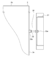
- FIG. 5 is an enlarged view showing the steady rest device 18 of FIG.
- Each of the steady rests 18 has a regulating member 21 provided on the mounting member 16 as a first steady stop target member and a stopper member 22 provided in the car chamber 2 as a second steady stop target member. are doing.
- the regulating member 21 has an L-shaped support part 23 fixed to the mounting member 16 and a steadying part 24 provided on the support part 23.
- the steady rest 24 has a jack bolt 24a and a rubber buffer 24b fixed to the end of the jack bolt 24a.
- the steady rest part 24 is attached to the support part 23 in a state in which the jack bolt 24 a is fitted in the screw hole formed in the support part 23. Further, the jack bolts 24 a are arranged along the width direction of the car 1. In each of the steady rests 18, the steady rest 24 is disposed with the buffer portion 24b facing inward in the width direction of the car 1. The position of the steady rest 24 with respect to the mounting member 16 and the support 23 can be adjusted in the width direction of the car 1 by the rotation of the jack bolt 24a.
- the stopper member 22 is a member having an L-shaped cross section fixed to the ceiling upper surface 2 b of the cab 2.
- the stopper member 22 is disposed on the inner side in the width direction of the car 1 than the regulating member 21.
- An abutting surface against which the buffer portion 24b hits is formed on the protruding portion of the stopper member 22 protruding upward from the ceiling upper surface 2b of the cab 2.
- the regulating member 21 receives the car chamber 2 via the stopper member 22 in the width direction of the car 1.
- the displacement of each mounting member 16 with respect to the car room 2 is limited in the width direction of the car 1 when the regulating member 21 receives the car room 2 via the stopper member 22.
- a pair of steadying devices 18 are provided between each of the pair of mounting members 16 and the car room 2. For this reason, the displacement of each attachment member 16 can be received in the cab 2 via each steadying device 18.
- the strength of each mounting member 16 can be reduced, and each mounting member 16 can be reduced in size and weight.
- each steadying apparatus 18 is arrange
- each mounting member 16 that supports the car door device 8 is provided in the car frame 3. For this reason, compared with the case where the door frame 10 of the car door device 8 is directly fixed to the car room 2, the vibration caused by the operation of the car door device 8 can be made difficult to be transmitted to the car room 2. Noise and vibration can be reduced. Further, when the car room 2 is supported by the car frame 3 via the vibration isolating rubber, if the door frame 10 of the car door device 8 is directly fixed to the car room 2, the car room is, for example, when passengers get in and out of the car room 2. 2 swings with respect to the car frame 3, and the position of the car door device 8 easily shifts with respect to the car frame 3.
- the positional deviation of the car door device 8 with respect to the car frame 3 can be prevented.
- the car door device 8 can be prevented from coming into contact with the engaging portion of the landing door device when the car 1 is moved.
- the car door 12 of the car door device 8 can be made difficult to come off from the door rail 11.
- each of the attachment members 16 and each of the steady rests 18 is disposed outside the range of the car doorway 4 in the width direction of the car 1. For this reason, it can avoid that each attachment member 16 and each steadying apparatus 18 interfere with the apparatus installed in the ceiling upper surface 2b of the cab 2. Thereby, the layout design of the apparatus in the ceiling upper surface 2b of the cab 2 can be facilitated. Moreover, since it is not necessary to arrange each attachment member 16 and each steady rest device 18 at a position higher than the equipment installed on the ceiling upper surface 2b of the car room 2, the overall height of the car 1 can be reduced. Can be planned.
- Each of the pair of steady rests 18 includes a regulating member 21 provided on the mounting member 16 and a stopper member 22 provided on the car room 2. For this reason, for example, even when the regulating member 21 does not face the side surface 2e of the cab 2 and the width direction of the car 1, the stopper member 22 fixed to the cab 2 faces the regulating member 21 in the width direction of the car 1. By doing so, the displacement of the attachment member 16 in the width direction of the car 1 can be received by the car room 2.
- the position of the jack bolt 24 a relative to the support portion 23 can be adjusted in the width direction of the car 1. For this reason, the position of each attachment member 16 with respect to the car room 2 can be adjusted in the width direction of the car 1, and the position of the car door device 8 with respect to the car doorway 4 can be easily adjusted in the width direction of the car 1. .
- the mounting member 16 fixed to the vertical column 7 is held horizontally by the vertical bars 17.
- the attachment member 16 can be held horizontally by the vertical column 7, there is no need for the vertical bars 17.
- the cross-sectional shape of the mounting member 16 is L-shaped.
- the cross-sectional shape of the attachment member 16 is not limited to this, and may be any shape.
- the mounting member 16 may be a flat plate, and the mounting member 16 may be arranged such that the thickness direction of the flat plate coincides with the width direction of the car 1.
- the first steadying target member provided with the regulating member 21 is the mounting member 16, and the second steadying target member provided with the stopper member 22 is the cab 2. .
- the first steadying target member provided with the regulating member 21 may be the car chamber 2
- the second steadying target member provided with the stopper member 22 may be the mounting member 16.
- the stopper member 22 is arranged on the inner side in the width direction of the car 1 than the regulating member 21 in each steadying device 18.
- the stopper member 22 may be arranged on the outer side in the width direction of the car 1 with respect to the restraining member 21 in each steadying device 18.
- the buffer portion 24b is fixed to the jack bolt 24a.
- the buffer portion 24b may be fixed to the stopper member 22 without fixing the buffer portion 24b to the jack bolt 24a.
- the jack bolt 24 a is attached to the support portion 23 fixed to the attachment member 16.
- the jack bolt 24 a may be directly attached to the attachment member 16 by fitting the jack bolt 24 a into the screw hole formed in the attachment member 16. In this way, the support part 23 can be eliminated, and the number of parts of the steady rest device 18 can be reduced.
- each mounting member 16 is supported only by the car frame 3.
- a pair of reinforcing columns reaching the lower part of the car 1 from each of the mounting members 16 may be added, and the mounting members 16 may be supported by the car frame 3 and the pair of reinforcing columns. If it does in this way, even when a torsional force acts on each attachment member 16 by operation
- the torsional rigidity of each mounting member 16 can be reinforced by the tensile strength and the compressive strength in the longitudinal direction of each reinforcing column, the thickness of the pair of reinforcing columns can be reduced. Can be reduced in weight.
- FIG. FIG. 6 is a schematic perspective view showing a car provided with an elevator door support device according to Embodiment 2 of the present invention.
- the height from the upper end of the car doorway 4 to the ceiling upper surface 2b of the car room 2 is higher than that in the first embodiment.
- the lower surface and upper surface of the door frame 10 of the car door apparatus 8 are both arrange
- FIG. 7 is a front view showing the car 1 of FIG.
- FIG. 8 is a top view showing the car 1 of FIG.
- FIG. 9 is a side view showing the car 1 of FIG.
- the door support device 9 includes a pair of mounting members 31 fixed to the car frame 3 and a pair of steadying devices for individually limiting displacement of the pair of mounting members 31 relative to the car room 2 in the width direction of the car 1. 32.
- the pair of mounting members 31 are individually fixed to the pair of vertical columns 7. Further, each of the pair of attachment members 31 is disposed horizontally along the depth direction of the car 1. Further, the pair of attachment members 31 are arranged apart from each other in the width direction of the car 1. In this example, each of the pair of attachment members 31 is disposed outside the range of the car room 2 in the width direction of the car 1. Further, the thickness direction of each mounting member 31 coincides with the width direction of the car 1. Thereby, the dimension of each attachment member 31 in the height direction of the car 1 is larger than the dimension of each attachment member 31 in the width direction of the car 1.
- each of the pair of mounting members 31 is disposed at a position higher than the upper end portion of the car entrance 4 and lower than the ceiling upper surface 2b of the car room 2. Thereby, one attachment member 31 is opposed to one side surface 2e of the cab 2. The other attachment member 31 faces the other side surface 2e of the cab 2.
- Each of the pair of attachment members 31 has an entrance / exit side end 31a.
- the respective entrance / exit side end portions 31 a of the pair of attachment members 31 are arranged at positions closer to the car entrance 4 than the vertical column 7. Thereby, the respective entrance / exit side ends 31 a of the pair of attachment members 31 are arranged with the space above the car entrance 4 in the width direction of the car 1.
- the rear surface of the door frame 10 is attached to the respective entrance / exit end portions 31 a of the pair of attachment members 31 via the interposition members 19. Thereby, the car door device 8 is supported by the pair of attachment members 31.
- each attachment member 31 is horizontally fixed to each vertical column 7 without using the vertical cross 17 of the first embodiment.
- Each of the steady rests 32 is disposed between each of the pair of mounting members 31 and the cab 2. Moreover, each steadying apparatus 32 is arrange
- FIG. 10 is an enlarged view showing the steady rest device 32 of FIG.
- Each steadying device 32 has a regulating member 33 provided on a mounting member 31 as a first steadying target member.
- the regulating member 33 is provided at the entrance / exit side end 31 a of the mounting member 31.
- the regulating member 33 has a jack bolt 33a and a rubber buffer 33b fixed to the end of the jack bolt 33a.
- the restriction member 33 is attached to the attachment member 31 in a state where the jack bolt 33 a is passed through the through hole provided in the attachment member 31. Further, the jack bolts 33 a are arranged along the width direction of the car 1.
- the position of the restricting member 33 relative to the mounting member 31 can be adjusted in the width direction of the car 1.
- the position of the restriction member 33 relative to the attachment member 31 is fixed by tightening the attachment member 31 between two nuts attached to the jack bolt 33a.
- the jack bolt 33a may be fitted to the nut fixed to the mounting member 31, and the position of the regulating member 33 with respect to the mounting member 31 may be adjusted by the rotation of the jack bolt 33a.
- the restricting member 33 In each of the steady rests 32, the restricting member 33 is disposed with the buffer portion 33b facing inward in the width direction of the car 1. Therefore, the buffer portion 33 b of the restricting member 33 directly receives the side surface 2 e of the cab 2.
- the displacement of each attachment member 31 with respect to the car room 2 is limited in the width direction of the car 1 when the regulating member 33 receives the side surface 2e of the car room 2.
- Other configurations are the same as those in the first embodiment.
- the regulating member 33 directly receives the side surface 2 e of the car room 2, whereby the displacement of each mounting member 31 with respect to the car room 2 is limited in the width direction of the car 1. For this reason, the same effect as Embodiment 1 can be acquired. Further, since the regulating member 33 directly receives the side surface 2e of the car room 2, it is not necessary to provide an additional member of the steady rest device 32 in the car room 2 in order to limit the displacement of the mounting member 31 with respect to the car room 2. . Thereby, the number of parts of the door support device 9 can be reduced, and the cost can be reduced.
- each mounting member 31 in the height direction of the car 1 is larger than the dimension of each mounting member 31 in the width direction of the car 1. For this reason, the strength of each attachment member 31 in the height direction of the car 1 can be increased. As a result, the weight of the car door device 8 can be supported by the mounting members 31 even without the longitudinal bars 17 used in the first embodiment. Therefore, the number of parts of the door support device 9 can be reduced, and the cost can be reduced.
- the first connection portion 17 a of the longitudinal bar 17 used in the first embodiment is connected to the attachment member 31. It is also conceivable to connect the second connecting portion 17b of the longitudinal bars 17 to the upper frame 6 at a position on the inner side in the width direction of the cab 2 from the position of the first connecting portion 17a.
- the corners of the upper portion of the cab 2 and the longitudinal bars 17 Will interfere with the arrangement of the second connecting portion 17b of the vertical bar crossing 17 inside the cab 2 in the width direction.
- each mounting member 16 in the width direction of the car 1 is limited by the pair of steadying devices 32.
- the displacement of each attachment member 16 in the width direction of the car 1 is restricted by the longitudinal bars 17. Therefore, the displacement of each mounting member 16 in the width direction of the car 1 can be easily limited.
- the first steadying target member provided with the regulating member 33 is the mounting member 31.
- the first steadying target member provided with the regulating member 33 may be the cab 2.
- the regulating member 33 is provided on the side surface 2 e of the car room 2 with the buffer portion 33 b facing outward in the width direction of the car 1.
- the buffer portion 33 b of the regulating member 33 receives the mounting member 31, so that the displacement of each mounting member 31 with respect to the car room 2 is limited in the width direction of the car 1.
- the buffer portion 33b is fixed to the jack bolt 33a.
- the buffer portion 33b may be fixed to the side surface 2e of the cab 2 without fixing the buffer portion 33b to the jack bolt 33a.
- each mounting member 31 is supported only by the car frame 3.
- a pair of reinforcing columns reaching the lower part of the car 1 from each of the mounting members 31 may be added, and the mounting members 31 may be supported by the car frame 3 and the pair of reinforcing columns. If it does in this way, even when a torsional force acts on each attachment member 31 by operation
- the torsional rigidity of each mounting member 31 can be reinforced by the tensile strength and the compressive strength in the longitudinal direction of each reinforcing column, the thickness of the pair of reinforcing columns can be reduced. Can be reduced in weight.
Abstract
This elevator door support device comprises: a pair of attachment members that are located higher than the upper end of a car doorway and that support a car door device; and a pair of bracing devices that restrict the respective displacement, in the widthwise direction of the car doorway, of the pair of attachment members relative to a car chamber. The pair of bracing devices are respectively disposed between the car chamber and the corresponding attachment member of the pair of attachment members.
Description
この発明は、かご出入口を開閉するかごドア装置を支持するエレベータのドア支持装置に関するものである。
The present invention relates to an elevator door support device that supports a car door device that opens and closes a car doorway.
従来、かごドアを支持するドアフレームをかご出入口の上方に配置するために、かごの上部から下部に達する一対の柱をかご出入口の間口方向両側に配置し、一対の柱にドアフレームを固定したエレベータのドア装置が知られている(例えば特許文献1参照)。
Conventionally, in order to place the door frame that supports the car door above the car doorway, a pair of pillars that reach from the top to the bottom of the car are placed on both sides of the car doorway, and the door frame is fixed to the pair of pillars. An elevator door device is known (see, for example, Patent Document 1).
特許文献1に示されている従来のエレベータのドア装置では、かご出入口の間口方向両側に配置された一対の柱が大型の柱であるため、かご全体の重量が大きくなってしまう。
In the conventional elevator door device disclosed in Patent Document 1, since the pair of pillars arranged on both sides of the front / rear direction of the car entrance / exit are large pillars, the weight of the entire car is increased.
この発明は、上記のような課題を解決するためになされたものであり、かご全体の軽量化を図ることができるエレベータのドア支持装置を得ることを目的とする。
The present invention has been made to solve the above-described problems, and an object thereof is to obtain an elevator door support device capable of reducing the weight of the entire car.
この発明によるエレベータのドア支持装置は、かご出入口が設けられたかご室と、かご室を支持するかご枠とを有するかごに設けられ、かご出入口を開閉するかごドア装置を支持するエレベータのドア支持装置であって、かご出入口の間口方向へ互いに離して配置されているとともにかご枠にそれぞれ固定され、かご出入口の上端部よりも高い位置でかごドア装置を支持する一対の取付部材、及び一対の取付部材のそれぞれとかご室との間にそれぞれ配置され、かご室に対する一対の取付部材のそれぞれの変位をかご出入口の間口方向において制限する一対の振れ止め装置を備えている。
The elevator door support device according to the present invention is provided in a car having a car room provided with a car doorway and a car frame that supports the car room, and supports the car door device that opens and closes the car doorway. A pair of mounting members that are spaced apart from each other in the entrance direction of the car doorway and that are respectively fixed to the car frame and that support the car door device at a position higher than the upper end of the car doorway; A pair of steadying devices are provided between each of the mounting members and the car room, and restrict each displacement of the pair of mounting members relative to the car room in the direction of the entrance of the car.
この発明によるエレベータのドア支持装置によれば、かごドア装置を支持する取付部材の軽量化を図ることができ、その結果、かご全体の軽量化を図ることができる。
According to the elevator door support device of the present invention, the weight of the mounting member that supports the car door device can be reduced, and as a result, the weight of the entire car can be reduced.
以下、この発明の実施の形態について図面を参照して説明する。
実施の形態1.
図1は、この発明の実施の形態1によるエレベータのドア支持装置が設けられているかごを示す模式的な斜視図である。図において、昇降路内を上下方向へ移動するかご1は、かご室2と、かご室2を支持するかご枠3とを有している。 Embodiments of the present invention will be described below with reference to the drawings.
Embodiment 1 FIG.
FIG. 1 is a schematic perspective view showing a car provided with an elevator door support device according toEmbodiment 1 of the present invention. In the figure, a car 1 that moves in a vertical direction in a hoistway has a car room 2 and a car frame 3 that supports the car room 2.
実施の形態1.
図1は、この発明の実施の形態1によるエレベータのドア支持装置が設けられているかごを示す模式的な斜視図である。図において、昇降路内を上下方向へ移動するかご1は、かご室2と、かご室2を支持するかご枠3とを有している。 Embodiments of the present invention will be described below with reference to the drawings.
FIG. 1 is a schematic perspective view showing a car provided with an elevator door support device according to
かご室2は、床2a、天井上面2b、正面2c、背面2d及び一対の側面2eを有している。かご室2の正面2c及び背面2dは、かご1の奥行き方向において互いに対向している。かご室2の一対の側面2eは、かご1の幅方向において互いに対向している。かご室2の正面2cには、かご出入口4が設けられている。かご出入口4の間口方向は、かご1の幅方向と一致している。
The car room 2 has a floor 2a, a ceiling top surface 2b, a front surface 2c, a back surface 2d, and a pair of side surfaces 2e. The front surface 2 c and the back surface 2 d of the car room 2 face each other in the depth direction of the car 1. The pair of side surfaces 2 e of the car room 2 face each other in the width direction of the car 1. A car doorway 4 is provided in the front surface 2 c of the car room 2. The frontage direction of the car doorway 4 coincides with the width direction of the car 1.
かご枠3は、かご室2の床2aが載せられた下枠5と、かご室2の上方に配置された上枠6と、下枠5及び上枠6間を繋ぐ一対の縦柱7とを有している。
The car frame 3 includes a lower frame 5 on which the floor 2 a of the car room 2 is placed, an upper frame 6 disposed above the car room 2, and a pair of vertical columns 7 that connect between the lower frame 5 and the upper frame 6. have.
一対の縦柱7は、かご室2の幅方向両側に上下方向に沿って配置されている。これにより、一方の縦柱7は、かご室2の一方の側面2eと対向している。また、他方の縦柱7は、かご室2の他方の側面2eと対向している。一対の縦柱7は、かご1の奥行き方向におけるかご室2の中間位置にそれぞれ配置されている。
The pair of vertical columns 7 are arranged along the vertical direction on both sides in the width direction of the cab 2. Thereby, one vertical column 7 is opposed to one side surface 2 e of the cab 2. The other vertical column 7 faces the other side surface 2 e of the car room 2. The pair of vertical columns 7 are respectively arranged at intermediate positions of the car room 2 in the depth direction of the car 1.
図2は、図1のかご1を示す正面図である。図3は、図1のかご1を示す上面図である。図4は、図1のかご1を示す側面図である。かご1には、かご出入口4を開閉するかごドア装置8と、かごドア装置8を支持するドア支持装置9とが設けられている。
FIG. 2 is a front view showing the car 1 of FIG. FIG. 3 is a top view showing the car 1 of FIG. FIG. 4 is a side view showing the car 1 of FIG. The car 1 is provided with a car door device 8 that opens and closes the car doorway 4 and a door support device 9 that supports the car door device 8.
かごドア装置8は、図2に示すように、ドア支持装置9に取り付けられたドアフレーム10と、ドアフレーム10に固定されたドアレール11と、ドアレール11に移動可能に掛かっている一対のかごドア12と、一対のかごドア12を移動させる駆動機構13とを有している。
As shown in FIG. 2, the car door device 8 includes a door frame 10 attached to the door support device 9, a door rail 11 fixed to the door frame 10, and a pair of car doors movably hanging on the door rail 11. 12 and a drive mechanism 13 for moving the pair of car doors 12.
ドアフレーム10は、かご出入口4の上端部よりも高い位置に配置されている。ドアフレーム10の下面は、かご室2の天井上面2bよりも低い位置に配置されている。また、ドアフレーム10の上面は、かご室2の天井上面2bよりも高い位置に配置されている。これにより、ドアフレーム10の下部は、かご1の奥行き方向においてかご室2の正面2cに対向している。
The door frame 10 is arranged at a position higher than the upper end of the car doorway 4. The lower surface of the door frame 10 is disposed at a position lower than the ceiling upper surface 2 b of the cab 2. Further, the upper surface of the door frame 10 is arranged at a position higher than the ceiling upper surface 2 b of the cab 2. Thereby, the lower part of the door frame 10 faces the front surface 2 c of the car room 2 in the depth direction of the car 1.
ドアレール11は、かご出入口4の間口方向に沿って水平に配置されている。かご室2の幅方向におけるドアフレーム10及びドアレール11のそれぞれの長さは、かご室2の幅方向寸法よりも長くなっている。
The door rail 11 is horizontally arranged along the frontage direction of the car entrance 4. The lengths of the door frame 10 and the door rail 11 in the width direction of the car room 2 are longer than the width dimension of the car room 2.
一対のかごドア12は、ドアレール11の長手方向に沿って移動可能になっている。これにより、一対のかごドア12は、かご出入口4の間口方向へ移動可能になっている。一対のかごドア12は、かご出入口4の間口方向において互いに反対方向へ移動することによりかご出入口4を開閉する。
The pair of car doors 12 are movable along the longitudinal direction of the door rail 11. As a result, the pair of car doors 12 can move in the frontage direction of the car doorway 4. The pair of car doors 12 opens and closes the car doorway 4 by moving in opposite directions in the opening direction of the car doorway 4.
駆動機構13は、ドアフレーム10に設けられている。また、駆動機構13は、一対のかごドア12を移動させる駆動力を発生するモータ14と、モータ14の駆動力を一対のかごドア12に伝える動力伝達部15とを有している。一対のかごドア12は、モータ14の駆動力を動力伝達部15から受けることにより互いに反対方向へ移動する。
The drive mechanism 13 is provided on the door frame 10. The driving mechanism 13 includes a motor 14 that generates a driving force for moving the pair of car doors 12 and a power transmission unit 15 that transmits the driving force of the motor 14 to the pair of car doors 12. The pair of car doors 12 move in opposite directions by receiving the driving force of the motor 14 from the power transmission unit 15.
ドア支持装置9は、かご枠3に支持されている。また、ドア支持装置9は、かご枠3にそれぞれ固定された一対の取付部材16と、一対の取付部材16及びかご枠3に接続された保持部材である一対の縦筋交い17と、かご室2に対する一対の取付部材16のそれぞれの変位をかご1の幅方向において個別に制限する一対の振れ止め装置18とを有している。
The door support device 9 is supported by the car frame 3. The door support device 9 includes a pair of mounting members 16 fixed to the car frame 3, a pair of vertical members 17 that are holding members connected to the pair of mounting members 16 and the car frame 3, and the car room 2. And a pair of steady rests 18 for individually limiting the displacement of the pair of attachment members 16 in the width direction of the car 1.
一対の取付部材16は、一対の縦柱7に個別に固定されている。また、一対の取付部材16のそれぞれは、かご1の奥行き方向に沿って水平に配置されている。さらに、一対の取付部材16は、かご1の幅方向へ互いに離して配置されている。この例では、一対の取付部材16のそれぞれが、かご1の幅方向におけるかご出入口4の範囲よりも外側に配置されている。
The pair of mounting members 16 are individually fixed to the pair of vertical columns 7. Further, each of the pair of attachment members 16 is disposed horizontally along the depth direction of the car 1. Further, the pair of attachment members 16 are arranged apart from each other in the width direction of the car 1. In this example, each of the pair of attachment members 16 is disposed outside the range of the car doorway 4 in the width direction of the car 1.
また、一対の取付部材16のそれぞれは、かご出入口4の上端部よりも高い位置に配置されている。この例では、図4に示すように、一対の取付部材16のそれぞれがかご室2の天井上面2bよりも高い位置でかつ上枠6よりも低い位置に配置されている。また、この例では、図2に示すように、各取付部材16の断面形状がL字状になっている。
Further, each of the pair of mounting members 16 is disposed at a position higher than the upper end portion of the car doorway 4. In this example, as shown in FIG. 4, each of the pair of attachment members 16 is disposed at a position higher than the ceiling upper surface 2 b of the cab 2 and lower than the upper frame 6. Moreover, in this example, as shown in FIG. 2, the cross-sectional shape of each attachment member 16 is L-shaped.
一対の取付部材16のそれぞれは、出入口側端部16aを有している。一対の取付部材16のそれぞれの出入口側端部16aは、縦柱7よりもかご出入口4に近い位置に配置されている。これにより、一対の取付部材16のそれぞれの出入口側端部16aは、かご1の幅方向においてかご出入口4の上方の空間を挟んで配置されている。一対の取付部材16のそれぞれの出入口側端部16aには、ドアフレーム10の裏面が介在部材19を介して取り付けられている。これにより、かごドア装置8は、一対の取付部材16に支持されている。各介在部材19は、板を曲げて形成された部材である。
Each of the pair of attachment members 16 has an entrance / exit side end 16a. Each of the pair of attachment members 16 is disposed at a position closer to the car doorway 4 than the vertical column 7. Thereby, the respective entrance / exit side ends 16 a of the pair of attachment members 16 are arranged with the space above the car entrance 4 in the width direction of the car 1. The rear surface of the door frame 10 is attached to the respective entrance / exit end portions 16 a of the pair of attachment members 16 via intervening members 19. Thereby, the car door device 8 is supported by the pair of attachment members 16. Each interposed member 19 is a member formed by bending a plate.
各縦筋交い17は、第1接続部17aと、第2接続部17bと、第1接続部17a及び第2接続部17b間を繋ぐ棒状部17cとを有している。この例では、棒状部17cに取り付けられた接続金具が第1接続部17a及び第2接続部17bとしてそれぞれ用いられている。また、この例では、棒状部17cに対する第1接続部17a及び第2接続部17bのそれぞれの位置が棒状部17cの長手方向へ調整可能になっている。これにより、各縦筋交い17における第1接続部17aと第2接続部17bとの間の長さが調整可能になっている。
Each vertical bar crossing 17 has a first connecting portion 17a, a second connecting portion 17b, and a rod-like portion 17c that connects the first connecting portion 17a and the second connecting portion 17b. In this example, connection fittings attached to the rod-like portion 17c are used as the first connection portion 17a and the second connection portion 17b, respectively. Moreover, in this example, each position of the 1st connection part 17a and the 2nd connection part 17b with respect to the rod-shaped part 17c can be adjusted to the longitudinal direction of the rod-shaped part 17c. Thereby, the length between the 1st connection part 17a and the 2nd connection part 17b in each longitudinal cross 17 can be adjusted.
各縦筋交い17の第1接続部17aは、各取付部材16の中間部に個別に接続されている。各縦筋交い17の第2接続部17bは、上枠6の両端部に個別に接続されている。これにより、各縦筋交い17は、上枠6から下方に向かって縦柱7から離れる方向へ傾斜している。この例では、取付部材16に固定されたフック部材に第1接続部17aが掛けられることにより、第1接続部17aが取付部材16に接続されている。また、この例では、上枠6に固定されたフック部材に第2接続部17bが掛けられることにより、第2接続部17bが上枠6に接続されている。一対の取付部材16のそれぞれは、各縦筋交い17により水平に保持されている。
The first connecting portion 17a of each longitudinal bar crossing 17 is individually connected to the intermediate portion of each mounting member 16. The second connecting portions 17 b of the vertical bars 17 are individually connected to both end portions of the upper frame 6. Accordingly, each of the vertical bars 17 is inclined downward from the upper frame 6 in a direction away from the vertical column 7. In this example, the first connection portion 17 a is connected to the attachment member 16 by the first connection portion 17 a being hung on the hook member fixed to the attachment member 16. In this example, the second connecting portion 17 b is connected to the upper frame 6 by the second connecting portion 17 b being hooked on the hook member fixed to the upper frame 6. Each of the pair of attachment members 16 is held horizontally by each longitudinal bar 17.
一対の振れ止め装置18は、一対の取付部材16のそれぞれとかご室2との間にそれぞれ設けられている。また、各振れ止め装置18は、図3及び図4に示すように、縦筋交い17の第1接続部17aよりも取付部材16の出入口側端部16aに近い位置に配置されている。さらに、各振れ止め装置18は、図2及び図3に示すように、かご1の幅方向におけるかご出入口4の範囲よりも外側に配置されている。かご1の幅方向内側に向かう方向への各取付部材16の変位は、各振れ止め装置18によって個別に阻止される。これにより、かご室2に対する各取付部材16の変位が、かご1の幅方向において制限されている。なお、この例では、取付部材16が第1の振れ止め対象部材とされ、かご室2が第2の振れ止め対象部材とされている。
The pair of steady rests 18 are provided between each of the pair of attachment members 16 and the car room 2. Further, as shown in FIGS. 3 and 4, each of the steady rest devices 18 is disposed at a position closer to the entrance / exit side end portion 16 a of the attachment member 16 than the first connection portion 17 a of the longitudinal bars 17. Further, as shown in FIGS. 2 and 3, each of the steady rests 18 is disposed outside the range of the car doorway 4 in the width direction of the car 1. The displacement of each mounting member 16 in the direction toward the inner side in the width direction of the car 1 is individually prevented by each steadying device 18. Thereby, the displacement of each attachment member 16 with respect to the car room 2 is limited in the width direction of the car 1. In this example, the attachment member 16 is the first steadying target member, and the car room 2 is the second steadying target member.
図5は、図2の振れ止め装置18を示す拡大図である。各振れ止め装置18は、第1の振れ止め対象部材としての取付部材16に設けられた規制部材21と、第2の振れ止め対象部材としてのかご室2に設けられたストッパ部材22とを有している。
FIG. 5 is an enlarged view showing the steady rest device 18 of FIG. Each of the steady rests 18 has a regulating member 21 provided on the mounting member 16 as a first steady stop target member and a stopper member 22 provided in the car chamber 2 as a second steady stop target member. are doing.
規制部材21は、取付部材16に固定されたL字状の支持部23と、支持部23に設けられた振れ止め部24とを有している。
The regulating member 21 has an L-shaped support part 23 fixed to the mounting member 16 and a steadying part 24 provided on the support part 23.
振れ止め部24は、ジャッキボルト24aと、ジャッキボルト24aの端部に固定されているゴム製の緩衝部24bとを有している。振れ止め部24は、支持部23に形成されたねじ穴にジャッキボルト24aが嵌められた状態で支持部23に取り付けられている。また、ジャッキボルト24aは、かご1の幅方向に沿って配置されている。各振れ止め装置18では、緩衝部24bをかご1の幅方向内側に向けて振れ止め部24が配置されている。取付部材16及び支持部23に対する振れ止め部24の位置は、ジャッキボルト24aの回転により、かご1の幅方向へ調整可能になっている。
The steady rest 24 has a jack bolt 24a and a rubber buffer 24b fixed to the end of the jack bolt 24a. The steady rest part 24 is attached to the support part 23 in a state in which the jack bolt 24 a is fitted in the screw hole formed in the support part 23. Further, the jack bolts 24 a are arranged along the width direction of the car 1. In each of the steady rests 18, the steady rest 24 is disposed with the buffer portion 24b facing inward in the width direction of the car 1. The position of the steady rest 24 with respect to the mounting member 16 and the support 23 can be adjusted in the width direction of the car 1 by the rotation of the jack bolt 24a.
ストッパ部材22は、かご室2の天井上面2bに固定された断面L字状の部材である。また、ストッパ部材22は、規制部材21よりもかご1の幅方向内側に配置されている。かご室2の天井上面2bから上方へ突出するストッパ部材22の突出部には、緩衝部24bが当たる当り面が形成されている。これにより、規制部材21は、かご1の幅方向においてストッパ部材22を介してかご室2を受けている。かご室2に対する各取付部材16の変位は、規制部材21がストッパ部材22を介してかご室2を受けることにより、かご1の幅方向において制限される。
The stopper member 22 is a member having an L-shaped cross section fixed to the ceiling upper surface 2 b of the cab 2. The stopper member 22 is disposed on the inner side in the width direction of the car 1 than the regulating member 21. An abutting surface against which the buffer portion 24b hits is formed on the protruding portion of the stopper member 22 protruding upward from the ceiling upper surface 2b of the cab 2. Thereby, the regulating member 21 receives the car chamber 2 via the stopper member 22 in the width direction of the car 1. The displacement of each mounting member 16 with respect to the car room 2 is limited in the width direction of the car 1 when the regulating member 21 receives the car room 2 via the stopper member 22.
このようなエレベータのドア支持装置9では、一対の取付部材16のそれぞれとかご室2との間に一対の振れ止め装置18がそれぞれ設けられている。このため、各振れ止め装置18を介して各取付部材16の変位をかご室2で受けることができる。これにより、例えば、かごドア12の移動の反転時の加減速によって各取付部材16に荷重が加わる場合、かご室2に対して各取付部材16をかご1の幅方向へ変位しにくくすることができる。従って、各取付部材16の強度を小さくすることができ、各取付部材16の小型化及び軽量化を図ることができる。また、一対の取付部材16のそれぞれとかご室2との間に各振れ止め装置18が配置されることから、各振れ止め装置18の小型化及び軽量化も図ることができる。このようなことから、ドア支持装置9を小型化及び軽量化することができ、かご1の全体の軽量化を図ることができる。さらに、かご1の幅方向における各取付部材16の寸法を大きくする必要がなくなることから、かご1の全体の幅方向寸法の増大を防止することもでき、昇降路の水平断面積の増大を抑制することができる。
In such an elevator door support device 9, a pair of steadying devices 18 are provided between each of the pair of mounting members 16 and the car room 2. For this reason, the displacement of each attachment member 16 can be received in the cab 2 via each steadying device 18. Thereby, for example, when a load is applied to each attachment member 16 by acceleration / deceleration at the time of reversal of the movement of the car door 12, it is difficult to displace each attachment member 16 in the width direction of the car 1 with respect to the car room 2. it can. Therefore, the strength of each mounting member 16 can be reduced, and each mounting member 16 can be reduced in size and weight. Moreover, since each steadying apparatus 18 is arrange | positioned between each of a pair of attachment member 16 and the cab 2, each steadying apparatus 18 can also be reduced in size and weight. For this reason, the door support device 9 can be reduced in size and weight, and the overall weight of the car 1 can be reduced. Furthermore, since it is not necessary to increase the size of each mounting member 16 in the width direction of the car 1, it is possible to prevent an increase in the overall width direction dimension of the car 1 and to suppress an increase in the horizontal cross-sectional area of the hoistway. can do.
また、かごドア装置8を支持する各取付部材16は、かご枠3に設けられている。このため、かごドア装置8のドアフレーム10をかご室2に直接固定する場合に比べて、かごドア装置8の動作による振動をかご室2内に伝わりにくくすることができ、かご室2内の騒音及び振動を低減することができる。また、かご室2が防振ゴムを介してかご枠3に支持されている場合、かごドア装置8のドアフレーム10をかご室2に直接固定すると、例えばかご室2に対する乗客の乗降時にかご室2がかご枠3に対して揺れて、かごドア装置8の位置がかご枠3に対してずれやすくなる。しかし、本実施の形態では、かご枠3に対するかごドア装置8の位置ずれを防止することができる。これにより、例えば、かご1の移動時にかごドア装置8が乗場ドア装置の係合部に接触することを防止することができる。また、かごドア装置8のかごドア12がドアレール11から外れにくくすることもできる。
Further, each mounting member 16 that supports the car door device 8 is provided in the car frame 3. For this reason, compared with the case where the door frame 10 of the car door device 8 is directly fixed to the car room 2, the vibration caused by the operation of the car door device 8 can be made difficult to be transmitted to the car room 2. Noise and vibration can be reduced. Further, when the car room 2 is supported by the car frame 3 via the vibration isolating rubber, if the door frame 10 of the car door device 8 is directly fixed to the car room 2, the car room is, for example, when passengers get in and out of the car room 2. 2 swings with respect to the car frame 3, and the position of the car door device 8 easily shifts with respect to the car frame 3. However, in the present embodiment, the positional deviation of the car door device 8 with respect to the car frame 3 can be prevented. Thereby, for example, the car door device 8 can be prevented from coming into contact with the engaging portion of the landing door device when the car 1 is moved. Further, the car door 12 of the car door device 8 can be made difficult to come off from the door rail 11.
さらに、各取付部材16及び各振れ止め装置18のそれぞれは、かご1の幅方向におけるかご出入口4の範囲よりも外側に配置されている。このため、かご室2の天井上面2bに設置されている機器に対して各取付部材16及び各振れ止め装置18が干渉することを回避することができる。これにより、かご室2の天井上面2bにおける機器のレイアウト設計を容易にすることができる。また、かご室2の天井上面2bに設置された機器よりも高い位置に各取付部材16及び各振れ止め装置18を配置する必要がなくなることから、かご1の全体の高さ寸法の縮小化を図ることができる。
Furthermore, each of the attachment members 16 and each of the steady rests 18 is disposed outside the range of the car doorway 4 in the width direction of the car 1. For this reason, it can avoid that each attachment member 16 and each steadying apparatus 18 interfere with the apparatus installed in the ceiling upper surface 2b of the cab 2. Thereby, the layout design of the apparatus in the ceiling upper surface 2b of the cab 2 can be facilitated. Moreover, since it is not necessary to arrange each attachment member 16 and each steady rest device 18 at a position higher than the equipment installed on the ceiling upper surface 2b of the car room 2, the overall height of the car 1 can be reduced. Can be planned.
また、一対の振れ止め装置18のそれぞれは、取付部材16に設けられた規制部材21と、かご室2に設けられたストッパ部材22とを有している。このため、例えば、規制部材21がかご室2の側面2eとかご1の幅方向に対向していない場合でも、かご室2に固定したストッパ部材22を規制部材21にかご1の幅方向において対向させることによって、かご1の幅方向における取付部材16の変位をかご室2で受けるようにすることができる。
Each of the pair of steady rests 18 includes a regulating member 21 provided on the mounting member 16 and a stopper member 22 provided on the car room 2. For this reason, for example, even when the regulating member 21 does not face the side surface 2e of the cab 2 and the width direction of the car 1, the stopper member 22 fixed to the cab 2 faces the regulating member 21 in the width direction of the car 1. By doing so, the displacement of the attachment member 16 in the width direction of the car 1 can be received by the car room 2.
また、規制部材21では、支持部23に対するジャッキボルト24aの位置がかご1の幅方向へ調整可能になっている。このため、かご室2に対する各取付部材16の位置をかご1の幅方向へ調整することができ、かご出入口4に対するかごドア装置8の位置をかご1の幅方向へ容易に調整することができる。
In the restricting member 21, the position of the jack bolt 24 a relative to the support portion 23 can be adjusted in the width direction of the car 1. For this reason, the position of each attachment member 16 with respect to the car room 2 can be adjusted in the width direction of the car 1, and the position of the car door device 8 with respect to the car doorway 4 can be easily adjusted in the width direction of the car 1. .
なお、上記の例では、縦柱7に固定された取付部材16が縦筋交い17によって水平に保持されている。しかし、取付部材16が縦柱7に水平に保持可能であれば、縦筋交い17はなくてもよい。
In the above example, the mounting member 16 fixed to the vertical column 7 is held horizontally by the vertical bars 17. However, as long as the attachment member 16 can be held horizontally by the vertical column 7, there is no need for the vertical bars 17.
また、上記の例では、取付部材16の断面形状がL字状になっている。しかし、取付部材16の断面形状は、これに限定されず、どのような形状であってもよい。例えば、取付部材16を平板とし、平板の厚さ方向をかご1の幅方向と一致させて取付部材16を配置してもよい。
In the above example, the cross-sectional shape of the mounting member 16 is L-shaped. However, the cross-sectional shape of the attachment member 16 is not limited to this, and may be any shape. For example, the mounting member 16 may be a flat plate, and the mounting member 16 may be arranged such that the thickness direction of the flat plate coincides with the width direction of the car 1.
また、上記の例では、規制部材21が設けられた第1の振れ止め対象部材が取付部材16とされ、ストッパ部材22が設けられた第2の振れ止め対象部材がかご室2とされている。しかし、規制部材21が設けられた第1の振れ止め対象部材をかご室2とし、ストッパ部材22が設けられた第2の振れ止め対象部材を取付部材16としてもよい。
In the above example, the first steadying target member provided with the regulating member 21 is the mounting member 16, and the second steadying target member provided with the stopper member 22 is the cab 2. . However, the first steadying target member provided with the regulating member 21 may be the car chamber 2, and the second steadying target member provided with the stopper member 22 may be the mounting member 16.
また、上記の例では、各振れ止め装置18においてストッパ部材22が規制部材21よりもかご1の幅方向内側に配置されている。しかし、各振れ止め装置18において規制部材21よりもかご1の幅方向外側にストッパ部材22を配置してもよい。
Further, in the above example, the stopper member 22 is arranged on the inner side in the width direction of the car 1 than the regulating member 21 in each steadying device 18. However, the stopper member 22 may be arranged on the outer side in the width direction of the car 1 with respect to the restraining member 21 in each steadying device 18.
また、上記の例では、緩衝部24bがジャッキボルト24aに固定されている。しかし、ジャッキボルト24aに緩衝部24bを固定せずに、ストッパ部材22に緩衝部24bを固定してもよい。
In the above example, the buffer portion 24b is fixed to the jack bolt 24a. However, the buffer portion 24b may be fixed to the stopper member 22 without fixing the buffer portion 24b to the jack bolt 24a.
また、上記の例では、取付部材16に固定された支持部23にジャッキボルト24aが取り付けられている。しかし、取付部材16に形成されたねじ穴にジャッキボルト24aを嵌めることにより、ジャッキボルト24aを取付部材16に直接取り付けてもよい。このようにすれば、支持部23をなくすことができ、振れ止め装置18の部品点数の低減化を図ることができる。
In the above example, the jack bolt 24 a is attached to the support portion 23 fixed to the attachment member 16. However, the jack bolt 24 a may be directly attached to the attachment member 16 by fitting the jack bolt 24 a into the screw hole formed in the attachment member 16. In this way, the support part 23 can be eliminated, and the number of parts of the steady rest device 18 can be reduced.
また、上記の例では、各取付部材16がかご枠3のみに支持されている。しかし、各取付部材16のそれぞれからかご1の下部に達する一対の補強柱を追加して、かご枠3及び一対の補強柱によって各取付部材16を支持してもよい。このようにすれば、例えばかごドア装置8の動作によって各取付部材16にねじり力が作用する場合でも、一対の補強柱によって各取付部材16を変形しにくくすることができる。この場合、各補強柱の長手方向の引張強度及び圧縮強度によって各取付部材16のねじり剛性を補強することができることから、一対の補強柱の太さを細くすることができ、かご1の全体としては軽量化を図ることができる。
In the above example, each mounting member 16 is supported only by the car frame 3. However, a pair of reinforcing columns reaching the lower part of the car 1 from each of the mounting members 16 may be added, and the mounting members 16 may be supported by the car frame 3 and the pair of reinforcing columns. If it does in this way, even when a torsional force acts on each attachment member 16 by operation | movement of the car door apparatus 8, for example, it can make it difficult to deform | transform each attachment member 16 with a pair of reinforcement pillar. In this case, since the torsional rigidity of each mounting member 16 can be reinforced by the tensile strength and the compressive strength in the longitudinal direction of each reinforcing column, the thickness of the pair of reinforcing columns can be reduced. Can be reduced in weight.
実施の形態2.
図6は、この発明の実施の形態2によるエレベータのドア支持装置が設けられているかごを示す模式的な斜視図である。本実施の形態では、かご出入口4の上端部からかご室2の天井上面2bまでの高さが実施の形態1よりも高くなっている。これにより、本実施の形態では、かごドア装置8のドアフレーム10の下面及び上面がいずれも、かご室2の天井上面2bよりも低い位置に配置されている。Embodiment 2. FIG.
FIG. 6 is a schematic perspective view showing a car provided with an elevator door support device according toEmbodiment 2 of the present invention. In the present embodiment, the height from the upper end of the car doorway 4 to the ceiling upper surface 2b of the car room 2 is higher than that in the first embodiment. Thereby, in this Embodiment, the lower surface and upper surface of the door frame 10 of the car door apparatus 8 are both arrange | positioned in the position lower than the ceiling upper surface 2b of the cab 2.
図6は、この発明の実施の形態2によるエレベータのドア支持装置が設けられているかごを示す模式的な斜視図である。本実施の形態では、かご出入口4の上端部からかご室2の天井上面2bまでの高さが実施の形態1よりも高くなっている。これにより、本実施の形態では、かごドア装置8のドアフレーム10の下面及び上面がいずれも、かご室2の天井上面2bよりも低い位置に配置されている。
FIG. 6 is a schematic perspective view showing a car provided with an elevator door support device according to
図7は、図6のかご1を示す正面図である。図8は、図6のかご1を示す上面図である。図9は、図6のかご1を示す側面図である。ドア支持装置9は、かご枠3にそれぞれ固定された一対の取付部材31と、かご室2に対する一対の取付部材31のそれぞれの変位をかご1の幅方向において個別に制限する一対の振れ止め装置32とを有している。
FIG. 7 is a front view showing the car 1 of FIG. FIG. 8 is a top view showing the car 1 of FIG. FIG. 9 is a side view showing the car 1 of FIG. The door support device 9 includes a pair of mounting members 31 fixed to the car frame 3 and a pair of steadying devices for individually limiting displacement of the pair of mounting members 31 relative to the car room 2 in the width direction of the car 1. 32.
一対の取付部材31は、一対の縦柱7に個別に固定されている。また、一対の取付部材31のそれぞれは、かご1の奥行き方向に沿って水平に配置されている。さらに、一対の取付部材31は、かご1の幅方向へ互いに離して配置されている。この例では、一対の取付部材31のそれぞれが、かご1の幅方向におけるかご室2の範囲よりも外側に配置されている。また、各取付部材31の厚さ方向は、かご1の幅方向と一致している。これにより、かご1の高さ方向における各取付部材31の寸法は、かご1の幅方向における各取付部材31の寸法よりも大きくなっている。
The pair of mounting members 31 are individually fixed to the pair of vertical columns 7. Further, each of the pair of attachment members 31 is disposed horizontally along the depth direction of the car 1. Further, the pair of attachment members 31 are arranged apart from each other in the width direction of the car 1. In this example, each of the pair of attachment members 31 is disposed outside the range of the car room 2 in the width direction of the car 1. Further, the thickness direction of each mounting member 31 coincides with the width direction of the car 1. Thereby, the dimension of each attachment member 31 in the height direction of the car 1 is larger than the dimension of each attachment member 31 in the width direction of the car 1.
また、一対の取付部材31のそれぞれは、かご出入口4の上端部よりも高い位置でかつかご室2の天井上面2bよりも低い位置に配置されている。これにより、一方の取付部材31は、かご室2の一方の側面2eと対向している。また、他方の取付部材31は、かご室2の他方の側面2eと対向している。
Further, each of the pair of mounting members 31 is disposed at a position higher than the upper end portion of the car entrance 4 and lower than the ceiling upper surface 2b of the car room 2. Thereby, one attachment member 31 is opposed to one side surface 2e of the cab 2. The other attachment member 31 faces the other side surface 2e of the cab 2.
一対の取付部材31のそれぞれは、出入口側端部31aを有している。一対の取付部材31のそれぞれの出入口側端部31aは、縦柱7よりもかご出入口4に近い位置に配置されている。これにより、一対の取付部材31のそれぞれの出入口側端部31aは、かご1の幅方向においてかご出入口4の上方の空間を挟んで配置されている。一対の取付部材31のそれぞれの出入口側端部31aには、ドアフレーム10の裏面が介在部材19を介して取り付けられている。これにより、かごドア装置8は、一対の取付部材31に支持されている。この例では、実施の形態1の縦筋交い17を用いずに各取付部材31が各縦柱7に水平に固定されている。
Each of the pair of attachment members 31 has an entrance / exit side end 31a. The respective entrance / exit side end portions 31 a of the pair of attachment members 31 are arranged at positions closer to the car entrance 4 than the vertical column 7. Thereby, the respective entrance / exit side ends 31 a of the pair of attachment members 31 are arranged with the space above the car entrance 4 in the width direction of the car 1. The rear surface of the door frame 10 is attached to the respective entrance / exit end portions 31 a of the pair of attachment members 31 via the interposition members 19. Thereby, the car door device 8 is supported by the pair of attachment members 31. In this example, each attachment member 31 is horizontally fixed to each vertical column 7 without using the vertical cross 17 of the first embodiment.
各振れ止め装置32は、一対の取付部材31のそれぞれとかご室2との間に配置されている。また、各振れ止め装置32は、図7及び図8に示すように、かご1の幅方向におけるかご室2の範囲よりも外側に配置されている。かご1の幅方向内側に向かう方向への各取付部材31の変位は、各振れ止め装置32によって個別に阻止される。これにより、かご室2に対する各取付部材31の変位が、かご1の幅方向において制限される。
Each of the steady rests 32 is disposed between each of the pair of mounting members 31 and the cab 2. Moreover, each steadying apparatus 32 is arrange | positioned outside the range of the cage | basket | chamber 2 in the width direction of the cage | basket | car 1, as shown in FIG.7 and FIG.8. The displacement of each mounting member 31 in the direction toward the inner side in the width direction of the car 1 is individually prevented by each steadying device 32. Thereby, the displacement of each attachment member 31 with respect to the car room 2 is limited in the width direction of the car 1.
図10は、図7の振れ止め装置32を示す拡大図である。各振れ止め装置32は、第1の振れ止め対象部材としての取付部材31に設けられた規制部材33を有している。この例では、規制部材33が取付部材31の出入口側端部31aに設けられている。
FIG. 10 is an enlarged view showing the steady rest device 32 of FIG. Each steadying device 32 has a regulating member 33 provided on a mounting member 31 as a first steadying target member. In this example, the regulating member 33 is provided at the entrance / exit side end 31 a of the mounting member 31.
規制部材33は、ジャッキボルト33aと、ジャッキボルト33aの端部に固定されているゴム製の緩衝部33bとを有している。規制部材33は、取付部材31に設けられた貫通穴にジャッキボルト33aが通された状態で取付部材31に取り付けられている。また、ジャッキボルト33aは、かご1の幅方向に沿って配置されている。
The regulating member 33 has a jack bolt 33a and a rubber buffer 33b fixed to the end of the jack bolt 33a. The restriction member 33 is attached to the attachment member 31 in a state where the jack bolt 33 a is passed through the through hole provided in the attachment member 31. Further, the jack bolts 33 a are arranged along the width direction of the car 1.
取付部材31に対する規制部材33の位置は、かご1の幅方向へ調整可能になっている。この例では、ジャッキボルト33aに取り付けられた2つのナットの間で取付部材31が締め付けられることにより、取付部材31に対する規制部材33の位置が固定されている。なお、取付部材31に固定されたナットにジャッキボルト33aが嵌められ、ジャッキボルト33aの回転により、取付部材31に対する規制部材33の位置が調整されるようになっていてもよい。
The position of the restricting member 33 relative to the mounting member 31 can be adjusted in the width direction of the car 1. In this example, the position of the restriction member 33 relative to the attachment member 31 is fixed by tightening the attachment member 31 between two nuts attached to the jack bolt 33a. In addition, the jack bolt 33a may be fitted to the nut fixed to the mounting member 31, and the position of the regulating member 33 with respect to the mounting member 31 may be adjusted by the rotation of the jack bolt 33a.
各振れ止め装置32では、緩衝部33bをかご1の幅方向内側に向けて規制部材33が配置されている。従って、規制部材33の緩衝部33bは、かご室2の側面2eを直接受けている。かご室2に対する各取付部材31の変位は、規制部材33がかご室2の側面2eを受けることにより、かご1の幅方向において制限される。他の構成は、実施の形態1と同様である。
In each of the steady rests 32, the restricting member 33 is disposed with the buffer portion 33b facing inward in the width direction of the car 1. Therefore, the buffer portion 33 b of the restricting member 33 directly receives the side surface 2 e of the cab 2. The displacement of each attachment member 31 with respect to the car room 2 is limited in the width direction of the car 1 when the regulating member 33 receives the side surface 2e of the car room 2. Other configurations are the same as those in the first embodiment.
このようなエレベータのドア支持装置9では、規制部材33がかご室2の側面2eを直接受けることにより、かご室2に対する各取付部材31の変位がかご1の幅方向において制限される。このため、実施の形態1と同様の効果を得ることができる。また、規制部材33がかご室2の側面2eを直接受けることから、かご室2に対する取付部材31の変位を制限するために、振れ止め装置32の追加の部材をかご室2に設ける必要がなくなる。これにより、ドア支持装置9の部品点数を減らすことができ、コストの低減化を図ることができる。
In such an elevator door support device 9, the regulating member 33 directly receives the side surface 2 e of the car room 2, whereby the displacement of each mounting member 31 with respect to the car room 2 is limited in the width direction of the car 1. For this reason, the same effect as Embodiment 1 can be acquired. Further, since the regulating member 33 directly receives the side surface 2e of the car room 2, it is not necessary to provide an additional member of the steady rest device 32 in the car room 2 in order to limit the displacement of the mounting member 31 with respect to the car room 2. . Thereby, the number of parts of the door support device 9 can be reduced, and the cost can be reduced.
また、かご1の高さ方向における各取付部材31の寸法は、かご1の幅方向における各取付部材31の寸法よりも大きくなっている。このため、かご1の高さ方向における各取付部材31の強度を大きくすることができる。これにより、実施の形態1で用いられている縦筋交い17がなくても、かごドア装置8の重量を各取付部材31で支持することができる。従って、ドア支持装置9の部品点数を減らすことができ、コストの低減化を図ることができる。
In addition, the dimension of each mounting member 31 in the height direction of the car 1 is larger than the dimension of each mounting member 31 in the width direction of the car 1. For this reason, the strength of each attachment member 31 in the height direction of the car 1 can be increased. As a result, the weight of the car door device 8 can be supported by the mounting members 31 even without the longitudinal bars 17 used in the first embodiment. Therefore, the number of parts of the door support device 9 can be reduced, and the cost can be reduced.
また、かご室2に対する各取付部材31の変位をかご1の幅方向において制限するために、実施の形態1で用いられている縦筋交い17の第1接続部17aを取付部材31に接続し、第1接続部17aの位置よりもかご室2の幅方向内側の位置で縦筋交い17の第2接続部17bを上枠6に接続することも考えられる。しかし、実施の形態2のように、各取付部材31がかご室2の天井上面2bの位置よりも低い位置に配置されている場合には、かご室2の上部の角部と縦筋交い17とが干渉することにより、縦筋交い17の第2接続部17bをかご室2の幅方向内側に配置することが難しくなってしまう。これに対して、本実施の形態では、かご1の幅方向における各取付部材16の変位が一対の振れ止め装置32によって制限される。このため、各取付部材31がかご室2の天井上面2bの位置よりも低い位置に配置されている場合であっても、かご1の幅方向における各取付部材16の変位を縦筋交い17によって制限する必要がなくなり、かご1の幅方向における各取付部材16の変位を容易に制限することができる。
In addition, in order to limit the displacement of each attachment member 31 with respect to the car room 2 in the width direction of the car 1, the first connection portion 17 a of the longitudinal bar 17 used in the first embodiment is connected to the attachment member 31. It is also conceivable to connect the second connecting portion 17b of the longitudinal bars 17 to the upper frame 6 at a position on the inner side in the width direction of the cab 2 from the position of the first connecting portion 17a. However, when each attachment member 31 is disposed at a position lower than the position of the ceiling upper surface 2b of the cab 2 as in the second embodiment, the corners of the upper portion of the cab 2 and the longitudinal bars 17 Will interfere with the arrangement of the second connecting portion 17b of the vertical bar crossing 17 inside the cab 2 in the width direction. On the other hand, in the present embodiment, the displacement of each mounting member 16 in the width direction of the car 1 is limited by the pair of steadying devices 32. For this reason, even if each attachment member 31 is arranged at a position lower than the position of the ceiling upper surface 2 b of the car room 2, the displacement of each attachment member 16 in the width direction of the car 1 is restricted by the longitudinal bars 17. Therefore, the displacement of each mounting member 16 in the width direction of the car 1 can be easily limited.
なお、上記の例では、規制部材33が設けられた第1の振れ止め対象部材が取付部材31とされている。しかし、規制部材33が設けられた第1の振れ止め対象部材をかご室2としてもよい。この場合、規制部材33は、緩衝部33bをかご1の幅方向外側に向けてかご室2の側面2eに設けられる。また、この場合、規制部材33の緩衝部33bが取付部材31を受けることにより、かご室2に対する各取付部材31の変位がかご1の幅方向において制限される。
In the above example, the first steadying target member provided with the regulating member 33 is the mounting member 31. However, the first steadying target member provided with the regulating member 33 may be the cab 2. In this case, the regulating member 33 is provided on the side surface 2 e of the car room 2 with the buffer portion 33 b facing outward in the width direction of the car 1. In this case, the buffer portion 33 b of the regulating member 33 receives the mounting member 31, so that the displacement of each mounting member 31 with respect to the car room 2 is limited in the width direction of the car 1.
また、上記の例では、緩衝部33bがジャッキボルト33aに固定されている。しかし、ジャッキボルト33aに緩衝部33bを固定せずに、かご室2の側面2eに緩衝部33bを固定してもよい。
In the above example, the buffer portion 33b is fixed to the jack bolt 33a. However, the buffer portion 33b may be fixed to the side surface 2e of the cab 2 without fixing the buffer portion 33b to the jack bolt 33a.
また、上記の例では、各取付部材31がかご枠3のみに支持されている。しかし、各取付部材31のそれぞれからかご1の下部に達する一対の補強柱を追加して、かご枠3及び一対の補強柱によって各取付部材31を支持してもよい。このようにすれば、例えばかごドア装置8の動作によって各取付部材31にねじり力が作用する場合でも、一対の補強柱によって各取付部材31を変形しにくくすることができる。この場合、各補強柱の長手方向の引張強度及び圧縮強度によって各取付部材31のねじり剛性を補強することができることから、一対の補強柱の太さを細くすることができ、かご1の全体としては軽量化を図ることができる。
Further, in the above example, each mounting member 31 is supported only by the car frame 3. However, a pair of reinforcing columns reaching the lower part of the car 1 from each of the mounting members 31 may be added, and the mounting members 31 may be supported by the car frame 3 and the pair of reinforcing columns. If it does in this way, even when a torsional force acts on each attachment member 31 by operation | movement of the car door apparatus 8, for example, it can make it difficult to deform | transform each attachment member 31 with a pair of reinforcement pillar. In this case, since the torsional rigidity of each mounting member 31 can be reinforced by the tensile strength and the compressive strength in the longitudinal direction of each reinforcing column, the thickness of the pair of reinforcing columns can be reduced. Can be reduced in weight.
1 かご、2 かご室、2b 天井上面、2e 側面、3 かご枠、4 かご出入口、8 かごドア装置、9 ドア支持装置、16,31 取付部材、18,32 振れ止め装置、21,33 規制部材、22 ストッパ部材、24a,33a ジャッキボルト。
1 car, 2 car room, 2b ceiling top surface, 2e side surface, 3 car frame, 4 car doorway, 8 car door device, 9 door support device, 16, 31 mounting member, 18, 32 steady rest device, 21, 33 regulating member 22 stopper member, 24a, 33a jack bolt.
Claims (5)
- かご出入口が設けられたかご室と、前記かご室を支持するかご枠とを有するかごに設けられ、前記かご出入口を開閉するかごドア装置を支持するエレベータのドア支持装置であって、
前記かご出入口の間口方向へ互いに離して配置されているとともに前記かご枠にそれぞれ固定され、前記かご出入口の上端部よりも高い位置で前記かごドア装置を支持する一対の取付部材、及び
前記一対の取付部材のそれぞれと前記かご室との間にそれぞれ配置され、前記かご室に対する前記一対の取付部材のそれぞれの変位を前記かご出入口の間口方向において制限する一対の振れ止め装置
を備えているエレベータのドア支持装置。 An elevator door support device that is provided in a car having a car room provided with a car doorway and a car frame that supports the car room, and supports a car door device that opens and closes the car doorway,
A pair of mounting members that are spaced apart from each other in the opening direction of the car doorway and are fixed to the car frame and support the car door device at a position higher than the upper end of the car doorway; An elevator comprising a pair of steadying devices disposed between each of the mounting members and the car room, and restricting displacement of each of the pair of mounting members relative to the car room in a direction of an entrance of the car doorway Door support device. - 前記一対の振れ止め装置のそれぞれは、前記取付部材及び前記かご室のいずれか一方である第1の振れ止め対象部材に設けられた規制部材と、前記取付部材及び前記かご室のいずれか他方である第2の振れ止め対象部材に設けられたストッパ部材とを有し、
前記かご室に対する前記一対の取付部材のそれぞれの変位は、前記規制部材が前記ストッパ部材を介して前記第2の振れ止め対象部材を受けることにより、前記かご出入口の間口方向において制限される請求項1に記載のエレベータのドア支持装置。 Each of the pair of steady-rest devices includes a regulating member provided on a first steady-rest target member that is one of the attachment member and the cab, and one of the attachment member and the cab. A stopper member provided on a certain second steadying target member,
The displacement of each of the pair of attachment members with respect to the car room is limited in the front-and-rear direction of the car doorway when the restricting member receives the second steadying target member via the stopper member. The elevator door support device according to claim 1. - 前記一対の振れ止め装置のそれぞれは、前記取付部材及び前記かご室のいずれか一方である第1の振れ止め対象部材に設けられた規制部材を有し、
前記かご室に対する前記一対の取付部材のそれぞれの変位は、前記取付部材及び前記かご室のいずれか他方である第2の振れ止め対象部材を前記規制部材が直接受けることにより、前記かご出入口の間口方向において制限される請求項1に記載のエレベータのドア支持装置。 Each of the pair of steady rest devices has a regulating member provided on a first steady rest target member that is one of the mounting member and the cab.
The displacement of each of the pair of attachment members relative to the car room is such that the restriction member directly receives the second steadying target member which is the other of the attachment member and the car room, so The elevator door support device according to claim 1, which is restricted in direction. - 前記取付部材は、前記かご室の天井上面の位置よりも低い位置に配置されている請求項1又は請求項3に記載のエレベータのドア支持装置。 The elevator door support device according to claim 1 or 3, wherein the mounting member is disposed at a position lower than a position of a ceiling upper surface of the cab.
- 前記規制部材は、ジャッキボルトを有し、
前記第1の振れ止め対象部材に対する前記ジャッキボルトの位置は、前記かご出入口の間口方向へ調整可能になっている請求項2から請求項4のいずれか一項に記載のエレベータのドア支持装置。 The regulating member has a jack bolt,
The elevator door support device according to any one of claims 2 to 4, wherein a position of the jack bolt with respect to the first steadying target member is adjustable in a direction toward the front of the car doorway.
Priority Applications (1)
| Application Number | Priority Date | Filing Date | Title |
|---|---|---|---|
| PCT/JP2018/022974 WO2019239593A1 (en) | 2018-06-15 | 2018-06-15 | Elevator door support device |
Applications Claiming Priority (1)
| Application Number | Priority Date | Filing Date | Title |
|---|---|---|---|
| PCT/JP2018/022974 WO2019239593A1 (en) | 2018-06-15 | 2018-06-15 | Elevator door support device |
Publications (1)
| Publication Number | Publication Date |
|---|---|
| WO2019239593A1 true WO2019239593A1 (en) | 2019-12-19 |
Family
ID=68842458
Family Applications (1)
| Application Number | Title | Priority Date | Filing Date |
|---|---|---|---|
| PCT/JP2018/022974 WO2019239593A1 (en) | 2018-06-15 | 2018-06-15 | Elevator door support device |
Country Status (1)
| Country | Link |
|---|---|
| WO (1) | WO2019239593A1 (en) |
Cited By (1)
| Publication number | Priority date | Publication date | Assignee | Title |
|---|---|---|---|---|
| WO2023195166A1 (en) * | 2022-04-08 | 2023-10-12 | 三菱電機株式会社 | Elevator car device |
Citations (7)
| Publication number | Priority date | Publication date | Assignee | Title |
|---|---|---|---|---|
| JPS6040376U (en) * | 1983-08-24 | 1985-03-20 | 三菱電機株式会社 | Elevator car door equipment |
| JPH09156857A (en) * | 1995-12-13 | 1997-06-17 | Mitsubishi Electric Corp | Landing opening/closing device for elevator |
| JP2004299806A (en) * | 2003-03-28 | 2004-10-28 | Toshiba Elevator Co Ltd | Height adjustment device of elevator door hanger |
| JP2007168963A (en) * | 2005-12-21 | 2007-07-05 | Toshiba Elevator Co Ltd | Elevator door device |
| EP2179958A1 (en) * | 2007-10-18 | 2010-04-28 | Mitsubishi Electric Corporation | Elevator cage and its installation method |
| JP2011190059A (en) * | 2010-03-15 | 2011-09-29 | Toshiba Elevator Co Ltd | Elevator car |
| JP2012012226A (en) * | 2011-10-21 | 2012-01-19 | Mitsubishi Electric Corp | Elevator device |
-
2018
- 2018-06-15 WO PCT/JP2018/022974 patent/WO2019239593A1/en active Application Filing
Patent Citations (7)
| Publication number | Priority date | Publication date | Assignee | Title |
|---|---|---|---|---|
| JPS6040376U (en) * | 1983-08-24 | 1985-03-20 | 三菱電機株式会社 | Elevator car door equipment |
| JPH09156857A (en) * | 1995-12-13 | 1997-06-17 | Mitsubishi Electric Corp | Landing opening/closing device for elevator |
| JP2004299806A (en) * | 2003-03-28 | 2004-10-28 | Toshiba Elevator Co Ltd | Height adjustment device of elevator door hanger |
| JP2007168963A (en) * | 2005-12-21 | 2007-07-05 | Toshiba Elevator Co Ltd | Elevator door device |
| EP2179958A1 (en) * | 2007-10-18 | 2010-04-28 | Mitsubishi Electric Corporation | Elevator cage and its installation method |
| JP2011190059A (en) * | 2010-03-15 | 2011-09-29 | Toshiba Elevator Co Ltd | Elevator car |
| JP2012012226A (en) * | 2011-10-21 | 2012-01-19 | Mitsubishi Electric Corp | Elevator device |
Cited By (1)
| Publication number | Priority date | Publication date | Assignee | Title |
|---|---|---|---|---|
| WO2023195166A1 (en) * | 2022-04-08 | 2023-10-12 | 三菱電機株式会社 | Elevator car device |
Similar Documents
| Publication | Publication Date | Title |
|---|---|---|
| US9718644B2 (en) | Elevator car | |
| JP5411931B2 (en) | Hanging elevator car structure | |
| US20020005320A1 (en) | Elevator with drive unit supported by guide rail | |
| WO2019239593A1 (en) | Elevator door support device | |
| JP6058149B2 (en) | Elevator car | |
| JP5484572B2 (en) | Elevator car | |
| KR101487117B1 (en) | Elevator car | |
| JP2010241563A (en) | Elevator vibration-isolating device | |
| JP6604622B1 (en) | Elevator door support device | |
| JP5241205B2 (en) | Elevator plate | |
| WO2011039854A1 (en) | Elevator car frame | |
| KR101410539B1 (en) | Elevator car compartment and elevator car | |
| JP2000086126A (en) | Traction elevator | |
| JP2009220893A (en) | Car frame of elevator | |
| JP5355311B2 (en) | Elevator car doorway equipment | |
| JP2012041174A (en) | Elevator car | |
| JP7400958B2 (en) | Elevator vibration isolator | |
| JP6621992B2 (en) | Mechanical parking system | |
| JP2013166616A (en) | Elevator | |
| WO2023021645A1 (en) | Elevator car and elevator | |
| JP2004123273A (en) | Elevator passenger car | |
| JP2006036450A (en) | Elevator device | |
| JP2023028264A (en) | car and elevator | |
| JP5146076B2 (en) | Elevator landing equipment | |
| JP2001247282A (en) | Car of elevator |
Legal Events
| Date | Code | Title | Description |
|---|---|---|---|
| 121 | Ep: the epo has been informed by wipo that ep was designated in this application |
Ref document number: 18922701 Country of ref document: EP Kind code of ref document: A1 |
|
| NENP | Non-entry into the national phase |
Ref country code: DE |
|
| 122 | Ep: pct application non-entry in european phase |
Ref document number: 18922701 Country of ref document: EP Kind code of ref document: A1 |
|
| NENP | Non-entry into the national phase |
Ref country code: JP |