WO2019235094A1 - Overlapped composite component and method for manufacturing overlapped composite component - Google Patents
Overlapped composite component and method for manufacturing overlapped composite component Download PDFInfo
- Publication number
- WO2019235094A1 WO2019235094A1 PCT/JP2019/017386 JP2019017386W WO2019235094A1 WO 2019235094 A1 WO2019235094 A1 WO 2019235094A1 JP 2019017386 W JP2019017386 W JP 2019017386W WO 2019235094 A1 WO2019235094 A1 WO 2019235094A1
- Authority
- WO
- WIPO (PCT)
- Prior art keywords
- stitch
- protrusion
- skin material
- protrusions
- base material
- Prior art date
Links
Images


Classifications
-
- B—PERFORMING OPERATIONS; TRANSPORTING
- B32—LAYERED PRODUCTS
- B32B—LAYERED PRODUCTS, i.e. PRODUCTS BUILT-UP OF STRATA OF FLAT OR NON-FLAT, e.g. CELLULAR OR HONEYCOMB, FORM
- B32B3/00—Layered products comprising a layer with external or internal discontinuities or unevennesses, or a layer of non-planar form; Layered products having particular features of form
- B32B3/02—Layered products comprising a layer with external or internal discontinuities or unevennesses, or a layer of non-planar form; Layered products having particular features of form characterised by features of form at particular places, e.g. in edge regions
- B32B3/04—Layered products comprising a layer with external or internal discontinuities or unevennesses, or a layer of non-planar form; Layered products having particular features of form characterised by features of form at particular places, e.g. in edge regions characterised by at least one layer folded at the edge, e.g. over another layer ; characterised by at least one layer enveloping or enclosing a material
-
- B—PERFORMING OPERATIONS; TRANSPORTING
- B32—LAYERED PRODUCTS
- B32B—LAYERED PRODUCTS, i.e. PRODUCTS BUILT-UP OF STRATA OF FLAT OR NON-FLAT, e.g. CELLULAR OR HONEYCOMB, FORM
- B32B1/00—Layered products having a general shape other than plane
-
- B—PERFORMING OPERATIONS; TRANSPORTING
- B32—LAYERED PRODUCTS
- B32B—LAYERED PRODUCTS, i.e. PRODUCTS BUILT-UP OF STRATA OF FLAT OR NON-FLAT, e.g. CELLULAR OR HONEYCOMB, FORM
- B32B27/00—Layered products comprising a layer of synthetic resin
- B32B27/06—Layered products comprising a layer of synthetic resin as the main or only constituent of a layer, which is next to another layer of the same or of a different material
- B32B27/08—Layered products comprising a layer of synthetic resin as the main or only constituent of a layer, which is next to another layer of the same or of a different material of synthetic resin
-
- B—PERFORMING OPERATIONS; TRANSPORTING
- B32—LAYERED PRODUCTS
- B32B—LAYERED PRODUCTS, i.e. PRODUCTS BUILT-UP OF STRATA OF FLAT OR NON-FLAT, e.g. CELLULAR OR HONEYCOMB, FORM
- B32B27/00—Layered products comprising a layer of synthetic resin
- B32B27/30—Layered products comprising a layer of synthetic resin comprising vinyl (co)polymers; comprising acrylic (co)polymers
- B32B27/302—Layered products comprising a layer of synthetic resin comprising vinyl (co)polymers; comprising acrylic (co)polymers comprising aromatic vinyl (co)polymers, e.g. styrenic (co)polymers
-
- B—PERFORMING OPERATIONS; TRANSPORTING
- B32—LAYERED PRODUCTS
- B32B—LAYERED PRODUCTS, i.e. PRODUCTS BUILT-UP OF STRATA OF FLAT OR NON-FLAT, e.g. CELLULAR OR HONEYCOMB, FORM
- B32B27/00—Layered products comprising a layer of synthetic resin
- B32B27/30—Layered products comprising a layer of synthetic resin comprising vinyl (co)polymers; comprising acrylic (co)polymers
- B32B27/304—Layered products comprising a layer of synthetic resin comprising vinyl (co)polymers; comprising acrylic (co)polymers comprising vinyl halide (co)polymers, e.g. PVC, PVDC, PVF, PVDF
-
- B—PERFORMING OPERATIONS; TRANSPORTING
- B32—LAYERED PRODUCTS
- B32B—LAYERED PRODUCTS, i.e. PRODUCTS BUILT-UP OF STRATA OF FLAT OR NON-FLAT, e.g. CELLULAR OR HONEYCOMB, FORM
- B32B3/00—Layered products comprising a layer with external or internal discontinuities or unevennesses, or a layer of non-planar form; Layered products having particular features of form
- B32B3/02—Layered products comprising a layer with external or internal discontinuities or unevennesses, or a layer of non-planar form; Layered products having particular features of form characterised by features of form at particular places, e.g. in edge regions
-
- B—PERFORMING OPERATIONS; TRANSPORTING
- B32—LAYERED PRODUCTS
- B32B—LAYERED PRODUCTS, i.e. PRODUCTS BUILT-UP OF STRATA OF FLAT OR NON-FLAT, e.g. CELLULAR OR HONEYCOMB, FORM
- B32B3/00—Layered products comprising a layer with external or internal discontinuities or unevennesses, or a layer of non-planar form; Layered products having particular features of form
- B32B3/26—Layered products comprising a layer with external or internal discontinuities or unevennesses, or a layer of non-planar form; Layered products having particular features of form characterised by a particular shape of the outline of the cross-section of a continuous layer; characterised by a layer with cavities or internal voids ; characterised by an apertured layer
- B32B3/30—Layered products comprising a layer with external or internal discontinuities or unevennesses, or a layer of non-planar form; Layered products having particular features of form characterised by a particular shape of the outline of the cross-section of a continuous layer; characterised by a layer with cavities or internal voids ; characterised by an apertured layer characterised by a layer formed with recesses or projections, e.g. hollows, grooves, protuberances, ribs
-
- B—PERFORMING OPERATIONS; TRANSPORTING
- B32—LAYERED PRODUCTS
- B32B—LAYERED PRODUCTS, i.e. PRODUCTS BUILT-UP OF STRATA OF FLAT OR NON-FLAT, e.g. CELLULAR OR HONEYCOMB, FORM
- B32B7/00—Layered products characterised by the relation between layers; Layered products characterised by the relative orientation of features between layers, or by the relative values of a measurable parameter between layers, i.e. products comprising layers having different physical, chemical or physicochemical properties; Layered products characterised by the interconnection of layers
- B32B7/02—Physical, chemical or physicochemical properties
- B32B7/022—Mechanical properties
-
- B—PERFORMING OPERATIONS; TRANSPORTING
- B32—LAYERED PRODUCTS
- B32B—LAYERED PRODUCTS, i.e. PRODUCTS BUILT-UP OF STRATA OF FLAT OR NON-FLAT, e.g. CELLULAR OR HONEYCOMB, FORM
- B32B7/00—Layered products characterised by the relation between layers; Layered products characterised by the relative orientation of features between layers, or by the relative values of a measurable parameter between layers, i.e. products comprising layers having different physical, chemical or physicochemical properties; Layered products characterised by the interconnection of layers
- B32B7/04—Interconnection of layers
- B32B7/08—Interconnection of layers by mechanical means
- B32B7/09—Interconnection of layers by mechanical means by stitching, needling or sewing
-
- B—PERFORMING OPERATIONS; TRANSPORTING
- B32—LAYERED PRODUCTS
- B32B—LAYERED PRODUCTS, i.e. PRODUCTS BUILT-UP OF STRATA OF FLAT OR NON-FLAT, e.g. CELLULAR OR HONEYCOMB, FORM
- B32B2250/00—Layers arrangement
- B32B2250/02—2 layers
-
- B—PERFORMING OPERATIONS; TRANSPORTING
- B32—LAYERED PRODUCTS
- B32B—LAYERED PRODUCTS, i.e. PRODUCTS BUILT-UP OF STRATA OF FLAT OR NON-FLAT, e.g. CELLULAR OR HONEYCOMB, FORM
- B32B2250/00—Layers arrangement
- B32B2250/24—All layers being polymeric
-
- B—PERFORMING OPERATIONS; TRANSPORTING
- B32—LAYERED PRODUCTS
- B32B—LAYERED PRODUCTS, i.e. PRODUCTS BUILT-UP OF STRATA OF FLAT OR NON-FLAT, e.g. CELLULAR OR HONEYCOMB, FORM
- B32B2307/00—Properties of the layers or laminate
- B32B2307/50—Properties of the layers or laminate having particular mechanical properties
- B32B2307/51—Elastic
-
- B—PERFORMING OPERATIONS; TRANSPORTING
- B32—LAYERED PRODUCTS
- B32B—LAYERED PRODUCTS, i.e. PRODUCTS BUILT-UP OF STRATA OF FLAT OR NON-FLAT, e.g. CELLULAR OR HONEYCOMB, FORM
- B32B2605/00—Vehicles
- B32B2605/003—Interior finishings
-
- B—PERFORMING OPERATIONS; TRANSPORTING
- B60—VEHICLES IN GENERAL
- B60R—VEHICLES, VEHICLE FITTINGS, OR VEHICLE PARTS, NOT OTHERWISE PROVIDED FOR
- B60R13/00—Elements for body-finishing, identifying, or decorating; Arrangements or adaptations for advertising purposes
- B60R13/02—Internal Trim mouldings ; Internal Ledges; Wall liners for passenger compartments; Roof liners
Definitions
- the present disclosure relates to an overlap composite part and a method for manufacturing the overlap composite part.
- Patent Document 1 As a vehicle interior part such as a door trim, a luggage side trim, an instrument panel, etc., it has been proposed to use a laminated composite part having a structure in which a plurality of plate members made of synthetic resin are laminated in the thickness direction. For example, see Patent Document 1.
- the superposed composite component described in Patent Document 1 has a plate-like base material and a plate-like skin material provided so as to be superposed on the base material.
- the surface of the skin material facing the base material protrudes toward the surface of the base material so as to form a gap between the surface of the base material facing the base material (opposite surface).
- a plurality of minute protrusions are provided.
- the plurality of protrusions are deformed so as to bend through contact with the opposing surface of the base material. Due to this deformation, an appropriate reaction force can be obtained when the surface of the skin material is pressed with a finger or hand, so that an excellent tactile sensation is obtained.
- JP 2016-117470 A Japanese Unexamined Patent Publication No. Sho 63-199641
- the sewing work on the skin material can be easily performed.
- the tactile sensation varies between the stitch arrangement portion and the other portions in the superimposed composite part.
- An object of the present disclosure is to provide an overlapped composite part capable of suppressing variation in tactile sensation between a stitch arrangement part and other parts, and a manufacturing method for manufacturing the overlapped composite part.
- the superposed composite part includes a plate-like base material made of a resin material, a skin material arranged so as to be superposed on the base material, and stitches.
- the skin material has a plate-like main body portion extending along the base material so as to form a gap with the base material, and a plurality of protrusions projecting from a surface of the main body portion facing the base material. .
- the skin material is made of a resin material and can be elastically deformed.
- the stitch is formed on the main body portion by a sewing thread.
- the skin material includes a stitch portion extending linearly including a portion where the stitch is formed on the facing surface. In the stitch portion, the protrusion is not formed, and a protrusion extending along the stitch is provided.
- the superposed composite part includes a plate-like base material made of a resin material, a skin material arranged so as to be superposed on the base material, and stitches.
- the skin material has a plate-like main body portion extending along the base material so as to form a gap with the base material, and a plurality of protrusions projecting from a surface of the main body portion facing the base material.
- the skin material is made of a resin material and can be elastically deformed.
- the stitch is formed in the main body portion by a sewing thread.
- the skin material includes a stitch portion extending linearly including a portion where the stitch is formed on the facing surface.
- the manufacturing method uses, as a sewing device that forms the stitch, a sewing device that includes a pair of raised plates that extend in parallel in a direction in which a sewing object is fed to an inner edge of a needle hole in the needle plate, and the pair of raised plates
- the stitches are formed by sewing the stitch portion while feeding the skin material in one direction by the sewing device in a state where the protrusions are fitted between the tips of the stitches.
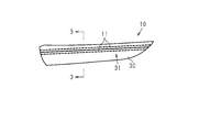
- FIG. 3 is a cross-sectional view taken along line 3-3 in FIG. 2.
- the side view which shows the opposing surface of a skin material.
- the side view which shows the arrangement
- the graph which shows the relationship between the amount of elastic deformation in the plate
- (A) is an exploded side view of the portion to be sewn in the sewing device
- (b) is an exploded front view of the portion to be sewn in the sewing device.
- the superposed composite part (hereinafter, interior part 10) constitutes a door trim as a vehicle interior part.
- the interior part 10 is arranged so as to be overlapped from the vehicle interior side, that is, the left side of FIG. 3, with the plate-like base material 20 disposed on the outside of the vehicle, that is, on the right side of FIG.
- the skin material 30 is provided.
- the interior component 10 is fixed to the vehicle door at the outer side of the vehicle compartment of the base material 20, that is, the right portion of FIG.
- the interior component 10 is disposed in a state where the skin material 30 is exposed to the vehicle interior side, that is, in a state where the surface side of the skin material 30, that is, the left surface in FIG.
- the base material 20 is made of a synthetic resin material such as ABS resin.
- the base material 20 has a plate shape that is curved in a convex shape that protrudes toward the vehicle interior side.
- the entire skin material 30 is made of a synthetic resin material softer than the base material 20, for example, soft polyvinyl chloride, and is formed to be elastically deformable.
- the skin material 30 includes a plate-like main body portion 32 extending along the base material 20.
- the main body 32 is curved in a convex shape that protrudes toward the vehicle interior side.
- the distance between the surface of the main body portion 32 facing the base material 20 (opposing surface 33) and the surface of the base material 20 facing the main body portion 32 (opposing surface 21) is substantially constant in each portion.
- the main body 32 is disposed.
- the main body portion 32 of the skin material 30 has two seams (stitch 11) formed by sewing threads. These stitches 11 have a seam shape that appears when so-called straight stitching is performed.
- the stitches 11 extend in parallel with each other and extend in the longitudinal direction of the skin material 30, that is, in the left-right direction in FIG.
- the skin material 30 has a plurality of protrusions 34 that protrude from the facing surface 33 of the main body portion 32 toward the facing surface 21 of the base material 20. These protrusions 34 are provided integrally with the main body portion 32. The protrusions 34 are arranged so as to be scattered in a range that occupies most of the facing surface 33 of the main body 32.
- each protrusion 34 has a substantially quadrangular pyramid shape and protrudes obliquely upward from the facing surface 33 of the main body 32. That is, each protrusion 34 extends in a state inclined at a predetermined inclination angle with respect to the vertical direction of the facing surface 33. Each protrusion 34 is chamfered so that all corners are rounded.
- the skin material 30 is fixed to the base material 20 in a state where the outer edge portion of the base material 20, that is, the upper end and the lower end of FIG. 3 are wound from the vehicle interior side to the vehicle interior outside.
- a load acts on the protrusion 34 through contact with the facing surface 21 of the base material 20 based on a decrease in the distance between the facing surface 21 of the base material 20 and the facing surface 33 of the main body portion 32.
- the protrusion 34 is elastically deformed so as to bend in the direction in which the inclination angle increases.
- a cushioning property is imparted to the interior part 10 by a reaction force generated along with the elastic deformation of the protrusion 34.
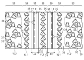
- the protrusion 34 is formed in a portion extending in a line shape having a predetermined width AR including the portion where the stitch 11 is formed on the facing surface 33 of the main body portion 32, that is, the stitch portion 36. Not formed. In other words, the protrusion 34 is formed only on the portion excluding the stitch portion 36 on the facing surface 33 of the main body portion 32.
- the stitch portion 36 is provided with a protrusion 35 extending along the stitch 11.
- the protrusion 35 extends in a substantially rectangular shape in cross section.
- a concave groove 37 extending in the width direction, that is, the center in the left-right direction in FIG.
- the stitch 11 is formed in a manner that can be sewn to the bottom of the concave groove 37.
- the protrusion height of the protrusion 35 where the stitch 11 is formed is the protrusion of both sides sandwiching the portion where the stitch 11 is formed. It is lower than the height.
- the skin material 30 is provided with such protrusions 35 for each of the two stitches 11.
- the two-dot chain line in FIG. 1 shows the protrusion 34 in a state in which the design surface 31 of the skin material 30 is pressed with a hand or a finger so that the amount of elastic deformation of the protrusion 34 becomes the maximum in the assumed range, that is, a so-called bottomed state. Yes.
- the protrusion height of the protrusion 35 from the facing surface 33 of the main body 32 is substantially the same as the protrusion height in the plate thickness direction of the protrusion 34 in the bottomed state. It has been established.
- the protrusion 34 is an imaginary portion extending along the protrusion 35 on the facing surface 33 of the main body 32 in a portion adjacent to the stitch portion 36 (the protrusion 35), that is, in the adjacent portion 38.
- the lines are arranged so as to line up on the virtual line VL1.
- the imaginary line VL1 extends in a sawtooth shape with an angle of a bent portion of 120 degrees. In other words, the virtual line VL1 extends in a zigzag manner.
- each protrusion 34 protrudes 1 each from the linear part in the said virtual line VL1.
- Each projection 34 is provided in a state slightly inclined in a direction perpendicular to the linear portion of the virtual line VL1 with respect to the vertical direction of the facing surface 33. Further, each projection 34 is provided in a state slightly inclined with respect to the direction perpendicular to the opposing surface 33 in the direction in which the skin material 30 is sent out when forming the stitch 11 by the sewing device 40, that is, in the direction opposite to the upper side in FIG. 5. ing. In the adjacent portion 38, when the projection 34 is elastically deformed by pressing the design surface 31 of the skin material 30 with a hand or a finger, the projection 34 does not come into contact with the other projection 34 or the protrusion 35. Each protrusion 34 is arranged.
- the adjacent portion 38 is defined at three locations, a portion sandwiching the two stitch portions 36 and a portion sandwiched between the two stitch portions 36.
- the portions sandwiching the two stitch portions 36 are portions located on the right and left sides of the two stitch portions 36 in FIG.
- the projections 34 are arranged in a complicated arrangement, such as by arranging the projections 34 in the portions corresponding to the sides of the hexagonal lattice-like imaginary line with respect to the adjacent portion 38 that is a portion extending along the protrusion 35. Therefore, the arrangement density of the protrusions 34 in the adjacent portion 38 varies.
- the protrusions 34 are provided so as to be arranged along the protrusions 35 in three adjacent portions 38, respectively. Therefore, as compared with the case where the protrusions 34 are arranged in a complicated arrangement, the protrusions 34 can be arranged in a state where variation in the arrangement density of the protrusions 34 in the direction along the protrusion 35 is suppressed. Thereby, the dispersion
- the protrusions 34 are arranged so as to line up on the virtual line VL ⁇ b> 1 extending in a sawtooth shape on the facing surface 33 of the main body portion 32. Therefore, a linear imaginary line extending along the ridge 35 is drawn on the facing surface 33 of the skin material 30 and the arrangement range of the projections 34 is made larger than when a plurality of projections are arranged on the imaginary line. be able to. Thereby, the reaction force obtained when pressing the skin material 30 can be set with a high degree of freedom.
- the protrusion 34 has a hexagonal lattice pattern on the opposing surface 33 of the main body 32 in most of the portion (general portion 39) excluding the stitch portion 36 and the adjacent portion 38.
- the imaginary line VL2 is provided at a position corresponding to each side of the hexagonal lattice.
- the general portion 39 corresponds to a portion adjacent to the adjacent portion 38.
- the protruding directions of the protrusions 34 corresponding to the three sides SA are alternately arranged in the circumferential direction of the hexagon.
- the protrusion 34 provided at the position corresponding to the side SA is slightly inclined inward of the hexagon with respect to the vertical direction of the facing surface 33, and slightly inclined clockwise in the circumferential direction of the hexagon. Protrusively protruding.
- each projection 34 is configured such that when the design surface 31 of the skin material 30 is pressed by a hand or a finger and the projection 34 is elastically deformed, the projection 34 does not contact the adjacent projection 34. Is arranged.
- the protrusions 34 are arranged in a complicated arrangement such that the protrusions 34 are arranged in the portions corresponding to the sides of the hexagons in the hexagonal lattice. Accordingly, the reaction force obtained when the skin material 30 is pressed can be generated in a balanced manner in each portion of the general portion 39 of the skin material 30, so that a good tactile sensation is provided in each portion of the general portion 39 of the skin material 30. It will be obtained.
- action by the interior component 10 is demonstrated. If the protrusions 35 are not provided, when the portion corresponding to the stitch portion 36 in the design surface 31 of the skin material 30 is pressed with a finger or hand, the main body portion 32 of the skin material 30 contacts the base material 20. Until the contact, the reaction force received from the skin material 30 remains small. On the other hand, when the part corresponding to the part (adjacent part 38 and general part 39) provided with the projection 34 on the design surface 31 of the skin material 30 is pressed with a finger or a hand, it projects from the main body part 32. The projected protrusion 34 comes into contact with the substrate 20 and elastically deforms.
- the reaction force that the finger or hand receives from the skin material 30 becomes large at a relatively early timing.
- a difference in timing at which a reaction force received by a finger or hand that presses the skin material 30 is large appears as a variation in tactile sensation in each part of the skin material 30.
- the protrusion 34 is not provided in the stitch portion 36 of the skin material 30, the protrusion 35 extending along the stitch 11 is provided in the stitch portion 36.
- the said protrusion 35 comes to contact
- FIG. Therefore, the reaction force received from the skin material 30 becomes large at an earlier timing than the interior part in which the protrusion 35 is not provided.
- the other part is a part corresponding to the adjacent part 38 and the general part 39. Therefore, variation in tactile sensation between the stitch arrangement portion and the other portion of the skin material 30 can be suppressed.
- the protruding height of the protrusion 35 from the facing surface 33 of the main body 32 is a state in which the design surface 31 of the skin material 30 is pressed so that the elastic deformation amount of the protrusion 34 becomes the maximum in the assumed range.
- the height of the protrusion 34 is set to be the same as the protrusion height of the protrusion 34.
- the stitch placement portion of the skin material 30 when the stitch placement portion of the skin material 30 is pressed, the stitch placement portion may be further elastically deformed after the elastic deformation around the stitch placement portion (portion other than the stitch placement portion) is saturated. It can be suppressed. Moreover, when the stitch arrangement
- the inventor conducted an experiment to measure the relationship between the amount of elastic deformation in the thickness direction of the skin material 30 and the reaction force received from the skin material 30 when the design surface 31 of the skin material 30 is pressed.
- the experimental results are shown in FIG.
- the solid line in FIG. 8 indicates the above relationship when the stitch arrangement portion of the skin material 30 of the interior part 10 is pressed and the above relationship when the portion other than the stitch arrangement portion is pressed. Since these relationships are substantially the same, they are indicated by the same line in FIG.
- the broken line of FIG. 8 has shown the said relationship when the stitch arrangement
- the reaction force (broken line) received from the skin material when the stitch placement portion is pressed is the reaction force received from the skin material when the portion other than the stitch placement portion is pressed. Smaller than force (see solid line).
- the reaction force (solid line) received from the skin material 30 when the stitch arrangement portion is pressed is received from the skin material 30 when the portion other than the stitch arrangement portion is pressed. It becomes almost the same as force.
- the needle plate 41 of the sewing apparatus 40 has two needle holes 43.
- Each needle hole 43 has a rectangular shape that extends in a manner in which the feeding direction DS, which is the direction in which the skin material 30 as a sewing object is fed, that is, the left-right direction in FIG.
- the needle holes 43 extend in parallel in a state in which they are arranged in the width direction DW, which is a direction orthogonal to the delivery direction DS, that is, in the left-right direction in FIG.
- the needle plate 41 is provided with four flat plate-like raising plates 44 that protrude upward from the inner edge of the needle hole 43, specifically, the portion corresponding to the long side of the rectangular shape, that is, upward in FIG. 9A. .
- Each needle plate 41 is provided with a pair of raised plates 44 for each needle hole 43.
- These raising plates 44 extend in parallel to each other, and each extend in the delivery direction DS along the inner edge of the needle hole 43.
- the protrusion height from the needle plate 41 of each raising plate 44 is higher than the protrusion height from the main body portion 32 of the skin material 30 of the protrusion 34 in a state where it is not elastically deformed.
- the sewing device 40 has a feed dog 45 for feeding the skin material 30 forward (hereinafter simply “front”) in the feed direction DS.
- the feed dog 45 is disposed below the needle plate 41, that is, below FIG. 9A.
- the feed dog 45 moves upward to hold down the skin material 30 from below, and forwards the skin material 30 forward by moving forward, that is, to the left side of FIG. 9A.
- the feed dog 45 has a structure in which the upper portion is bifurcated in the width direction DW, that is, in the left-right direction in FIG.
- the feed dog 45 is movable in the vertical direction and the feed direction DS in a state where the bifurcated portion at the top, that is, the branch portion 45A is inserted through the two needle holes 43 of the needle plate 41.
- Each branch portion 45A is provided with a notch 45B extending in the delivery direction DS so as to open behind the delivery direction DS (hereinafter simply referred to as “rear”).
- the notch 45B prevents the lower thread from getting in the way when the feed dog 45 moves in the feed direction DS.
- the sewing device 40 includes a presser foot 46 for pressing the skin material 30 from above when the stitch 11 is formed.
- the presser foot 46 presses the skin material 30 from above by moving downward so as to sandwich the skin material 30 between its lower surface and the tip of the raised plate 44.
- the presser foot 46 has an L-shape composed of an arm 46A extending in the vertical direction and a presser portion 46B extending rearward from the lower end of the arm 46A.
- the pressing portion 46B has a structure in which the rear side portion is bifurcated in the width direction DW.
- the pressing portion 46B is movable in the vertical direction. When the pressing portion 46B is moved downward, the lower surface of the pressing portion 46B comes into contact with the tip of the raising plate 44 arranged outside the four raising plates 44.
- the sewing device 40 has a feed leg 47 for feeding the skin material 30 forward.
- the feed leg 47 moves downward to press the skin material 30 from above and forwards the skin material 30 forward by moving forward, that is, to the left in FIG. 9A.
- the feed leg 47 has an L shape composed of an arm 47A extending in the vertical direction and a portion extending rearward from the lower end of the arm 47A, that is, a pair of branch portions 47B.
- the lower portion of the feed leg 47 has a structure bifurcated in the width direction DW, that is, the left-right direction in FIG.
- the feed leg 47 is movable in the vertical direction and in the feed direction DS in a state where a bifurcated portion (branch portion 47B) in the lower part is disposed above the two needle holes 43 of the needle plate 41.
- Each branch portion 47B is provided with a notch 47C extending in the delivery direction DS so as to open rearward.
- the cutout 47C prevents the sewing needle 48 and the upper thread from getting in the way when the feed dog 45 moves in the feed direction DS.
- Step 1 First, the base material 20 and the skin material 30 are formed separately by molding.
- Step 2 the skin material 30 is set in the sewing device 40. Specifically, the skin material 30 is first placed on the needle plate 41, specifically, the raising plate 44. At this time, as shown in FIG. 10, the two protrusions 35 of the main body portion 32 of the skin material 30 are fitted between the tips of the raising plate 44 of the needle plate 41 of the sewing device 40. Thereafter, the presser foot 46 is lowered. As a result, the skin material 30 is sandwiched between the presser foot 46 and the tip of the raising plate 44, and the skin material 30 is pressed by the presser foot 46, that is, the state shown in FIG.
- Step 3 The stitch 11 is formed through the sewing process by the sewing device 40.
- the stitch 11 is formed by sewing the stitch portion 36 while feeding the skin material 30 forward by the sewing device 40.
- the stitch 11 is formed in the stitch portion 36 of the skin material 30 by so-called linear stitching.
- the skin material 30 is guided in the feeding direction DS through the engagement between the pair of raised plates 44 of the needle plate 41 and the protrusions 35 of the skin material 30. Become so. As a result, the skin material 30 is guided in such a manner that an appropriate portion, specifically, the bottom of the concave groove 37 in the stitch portion 36 is sewn by the sewing device 40.
- the protrusions 35 are sandwiched between the pair of raised plates 44, the protrusions 34 can be prevented from entering the stitch portions 36 where the protrusions 35 are formed. Thereby, formation of the stitch 11 to the stitch part 36 can be performed without being disturbed by the protrusion 34. Therefore, according to the sewing device 40, the stitch 11 can be suitably formed on the skin material 30 having the plurality of protrusions 34.
- the protrusion 34 disposed in the adjacent portion 38 on the facing surface 33 of the skin material 30 protrudes in a manner inclined toward the rear side in the feeding direction DS.
- the protruding height of the portion of the ridge 35 of the skin material 30 on which the stitch 11 is formed is the both side portions sandwiching the portion where the stitch 11 is formed. It is lower than the protruding height. Therefore, although the protrusion 35 is provided in the stitch part 36 of the skin material 30, the thickness of the part in which the stitch 11 is formed in the skin material 30 can be made thin. Thereby, since resistance applied to the sewing needle 48 can be reduced when the stitch 11 is formed on the main body portion 32 of the skin material 30 by sewing, the stitch 11 can be easily formed.
- Step 4 The skin material 30 on which the stitch 11 is formed is fixed to the base material 20. As described above, according to the present embodiment, the following effects can be obtained. (1) A protrusion 35 extending along the stitch 11 is provided in the stitch portion 36 of the skin material 30. Therefore, variation in tactile sensation between the stitch arrangement portion and the other portions in the skin material 30 can be suppressed.
- the main body so as to be substantially the same as the protrusion height of the protrusion 34 in the bottomed state in which the design surface 31 of the skin material 30 is pressed with a hand or a finger so that the amount of elastic deformation of the protrusion 34 becomes the maximum in the assumed range.
- the protrusion height of the protrusion 35 from the facing surface 33 of the part 32 is determined. Therefore, variation in tactile sensation between the stitch arrangement portion and other portions in the skin material 30 can be suitably suppressed.
- the protrusions 34 are arranged so as to be aligned on the virtual line VL1.
- the protrusions 34 can be arranged in a state where variation in the arrangement density of the protrusions 34 in the direction along the protrusion 35 is suppressed.
- the protrusions 34 are arranged so as to line up on the virtual line VL1 extending in a sawtooth shape on the facing surface 33 of the main body portion 32.
- positioning range of the protrusion 34 can be enlarged compared with the case where a linear imaginary line is drawn on the opposing surface 33 of the skin material 30, and several protrusion is arrange
- the protruding height of the portion where the stitch 11 is formed in the protrusion 35 of the skin material 30 is set lower than the protruding height of the both side portions sandwiching the portion where the stitch 11 is formed. Yes. Thereby, although the protrusion 35 is provided in the stitch part 36 of the skin material 30, the resistance applied to the sewing needle 48 when the stitch 11 is formed on the main body part 32 of the skin material 30 by sewing processing is reduced. Can do. Therefore, the stitch 11 can be easily formed.
- the protrusion 34 disposed in the adjacent portion 38 on the facing surface 33 of the skin material 30 protrudes in a manner inclined toward the rear side in the delivery direction DS. Thereby, formation of the stitch 11 to the skin material 30 which has the some protrusion 34 can be performed more suitably.
- the above embodiment may be modified as follows.
- the protruding height of the raised plate 44 from the needle plate 41 is the same as the protruding height of the non-deformed protrusion from the facing surface 33 of the skin material 30 or slightly higher than the protruding height of the non-deformed protrusion 34. It may be lowered.
- the arrangement of the protrusions 34 in the adjacent portion 38 and the general portion 39 of the facing surface 33 of the skin material 30 can be arbitrarily changed.
- the protrusions 34 are arranged on the portions corresponding to the sides of each triangle in the triangular lattice, or the protrusions 34 are disposed on the portions corresponding to the sides of each square in the quadrangular lattice. You may do it.
- a straight imaginary line extending along the protrusion 35 may be drawn on the facing surface 33, and a plurality of protrusions 34 may be arranged on the imaginary line.
- the protrusions 34 in the adjacent part 38 and the general part 39 of the opposing surface 33 of the skin material 30, it is also possible to arrange the protrusions 34 in the same manner.
- the interior part 10 and the manufacturing method thereof according to the above embodiment are also applied to an interior part in which one stitch 11 is formed on the main body portion 32 of the skin material 30 or an interior part in which three or more stitches 11 are formed. be able to.
- the omission groove 37 of the ridge 35 is omitted, and the protruding height of the portion of the ridge 35 where the stitch 11 is formed is the same as the protruding height of both side portions sandwiching the portion where the stitch 11 is formed. There may be.
- the protrusion height of the protrusion 35 from the opposing surface 33 of the main body 32 may be determined to be different from the protrusion height in the plate thickness direction of the protrusion 34 in the bottomed state.
- the protrusion height of the protrusion 55 from the opposing surface 33 of the main body 52 is the protrusion height in the plate thickness direction of the protrusion 34 in the bottomed state, that is, in the state indicated by the two-dot chain line in FIG. It may be higher than that.
- the amount of elastic deformation of the protrusion 34 is opposed to the base 20 before the maximum amount of the assumed range is reached. It will be in the state which the surface 21 contact
- the maximum value of the elastic deformation amount in the plate thickness direction of the protrusion 34 when the range including the arrangement portion of the protrusion 55 on the design surface 31 of the skin material 50 is pressed is calculated. It can be adjusted through the setting of the protrusion height of the strip 55. Therefore, the tactile sensation of the skin material 50 can be set with a high degree of freedom.
- the superposed composite part and the manufacturing method thereof according to the above embodiment can be applied to interior parts for vehicles other than door trims such as luggage side trims and instrument panels.
Abstract
An overlapped composite component provided with: a plate-shaped base material made of a resin material; a skin material arranged so as to be overlapped with the base material; and a stitch. The skin material has a plate-shaped body part extending along the base material so as to form a gap between the body part and the base material, and a plurality of projections projecting from a surface of the body part that faces the base material. The skin material is made of a resin material and elastically deformable. The skin material is provided with a linearly-extending stitch part including a portion at which the stitch is formed. The stitch part does not have a projection and has a ridge extending along the stitch.
Description
本開示は、重ね合わせ複合部品および同重ね合わせ複合部品の製造方法に関するものである。
The present disclosure relates to an overlap composite part and a method for manufacturing the overlap composite part.
ドアトリムやラゲージサイドトリム、インストルメントパネル等の車両用内装部品として、合成樹脂製の板状部材が板厚方向に複数重ねられた構造の重ね合わせ複合部品を用いることが提案されている。例えば特許文献1参照。
As a vehicle interior part such as a door trim, a luggage side trim, an instrument panel, etc., it has been proposed to use a laminated composite part having a structure in which a plurality of plate members made of synthetic resin are laminated in the thickness direction. For example, see Patent Document 1.
特許文献1に記載の重ね合わせ複合部品は、板状の基材と、同基材に重ね合わされるように設けられた板状の表皮材とを有している。表皮材の基材と対向する面(対向面)には、基材の表皮材と対向する面(対向面)との間に隙間を形成するように、同基材の対向面に向かって突出する複数の微小突起が設けられている。こうした重ね合わせ複合部品では、表皮材の表面が基材に向かって指や手で押圧された際に、複数の突起が基材の対向面との接触を通じて撓むように変形する。この変形により、指や手で表皮材の表面を押圧した際に適度の反力が得られるようになるため、優れた触感が得られる。
The superposed composite component described in Patent Document 1 has a plate-like base material and a plate-like skin material provided so as to be superposed on the base material. The surface of the skin material facing the base material (opposite surface) protrudes toward the surface of the base material so as to form a gap between the surface of the base material facing the base material (opposite surface). A plurality of minute protrusions are provided. In such an overlaid composite part, when the surface of the skin material is pressed against the base material with a finger or hand, the plurality of protrusions are deformed so as to bend through contact with the opposing surface of the base material. Due to this deformation, an appropriate reaction force can be obtained when the surface of the skin material is pressed with a finger or hand, so that an excellent tactile sensation is obtained.
また車両用内装部品に、意匠性を向上させるために、縫製加工によって縫い目、いわゆるステッチを付与することが提案されている。特許文献2参照。
Also, it has been proposed to provide seams, so-called stitches, by sewing processing in order to improve the design properties of vehicle interior parts. See Patent Document 2.
ここで、上述した重ね合わせ複合部品に、意匠性の向上のためにステッチを付与することが考えられる。この場合には、重ね合わせ複合部品の表皮材に、ミシン等の縫製装置によって縫製加工が施されるようになる。上記重ね合わせ複合部品では、表皮材の裏面に複数の微小突起が設けられている。そのため、単に表皮材に縫製加工を施そうとすると、裏面の微小突起が邪魔になってしまい、縫製加工が困難になる。
Here, it is conceivable that stitches are imparted to the above-described overlapped composite parts in order to improve design properties. In this case, the sewing process is performed on the skin material of the superimposed composite part by a sewing device such as a sewing machine. In the superposed composite part, a plurality of minute protrusions are provided on the back surface of the skin material. For this reason, if an attempt is made to simply sew the skin material, the minute protrusions on the back surface will be in the way, making the sewing process difficult.
表皮材におけるステッチを付与する部分およびその周辺部分(ステッチ配置部分)に微小突起を配設しないようにすれば、表皮材への縫製加工を容易に行うことはできる。ただし、この場合には、重ね合わせ複合部品におけるステッチ配置部分とそれ以外の部分との間で、上記触感にばらつきが生じてしまう。
If the fine protrusions are not disposed in the portion to which the stitch is applied and the peripheral portion (stitch arrangement portion) in the skin material, the sewing work on the skin material can be easily performed. However, in this case, the tactile sensation varies between the stitch arrangement portion and the other portions in the superimposed composite part.
本開示の目的は、ステッチ配置部分とそれ以外の部分との間での触感のばらつきを抑えることができる重ね合わせ複合部品、および同重ね合わせ複合部品を製造する製造方法を提供することにある。
An object of the present disclosure is to provide an overlapped composite part capable of suppressing variation in tactile sensation between a stitch arrangement part and other parts, and a manufacturing method for manufacturing the overlapped composite part.
上記目的を達成するための一態様は、重ね合わせ複合部品を提供する。重ね合わせ複合部品は、樹脂材料からなる板状の基材と、前記基材に重ね合わされるように配置された表皮材と、ステッチとを備える。表皮材は、前記基材との間に隙間を形成するように同基材に沿って延びる板状の本体部、および同本体部の前記基材に対向する面から突出する複数の突起を有する。表皮材は、樹脂材料からなり弾性変形可能である、ステッチは、縫い糸によって前記本体部に形成されている。前記表皮材は、前記対向する面における前記ステッチが形成された部分を含んで線状に延びるステッチ部を備える。前記ステッチ部には、前記突起が形成されておらず、且つ、前記ステッチに沿って延びる突条が設けられている。
One aspect for achieving the above object provides an overlapped composite part. The superposed composite part includes a plate-like base material made of a resin material, a skin material arranged so as to be superposed on the base material, and stitches. The skin material has a plate-like main body portion extending along the base material so as to form a gap with the base material, and a plurality of protrusions projecting from a surface of the main body portion facing the base material. . The skin material is made of a resin material and can be elastically deformed. The stitch is formed on the main body portion by a sewing thread. The skin material includes a stitch portion extending linearly including a portion where the stitch is formed on the facing surface. In the stitch portion, the protrusion is not formed, and a protrusion extending along the stitch is provided.
前記目的を達成するための別の態様は、重ね合わせ複合部品の製造方法を提供する。重ね合わせ複合部品は、樹脂材料からなる板状の基材と、前記基材に重ね合わされるように配置された表皮材と、ステッチとを備える。表皮材は、前記基材との間に隙間を形成するように同基材に沿って延びる板状の本体部、および同本体部の前記基材に対向する面から突出する複数の突起を有する。表皮材は、樹脂材料からなり弾性変形可能である。ステッチは、縫い糸によって前記本体部に形成されている。前記表皮材は、前記対向する面における前記ステッチが形成される部分を含んで線状に延びるステッチ部を備える。前記ステッチ部には前記突起が形成されておらず且つ前記ステッチに沿って延びる突条が設けられている。前記製造方法は、前記ステッチを形成する縫製装置として、針板における針穴の内縁に、縫製対象物を送り出す方向において平行に延びる一対の嵩上げ板を備える縫製装置を用いること、前記一対の嵩上げ板の先端間に前記突条が嵌められた状態で、前記縫製装置により、前記表皮材を一方向に送り出しつつ前記ステッチ部を縫うことにより前記ステッチを形成することとを備える。
Another aspect for achieving the above object provides a method for manufacturing an overlapped composite part. The superposed composite part includes a plate-like base material made of a resin material, a skin material arranged so as to be superposed on the base material, and stitches. The skin material has a plate-like main body portion extending along the base material so as to form a gap with the base material, and a plurality of protrusions projecting from a surface of the main body portion facing the base material. . The skin material is made of a resin material and can be elastically deformed. The stitch is formed in the main body portion by a sewing thread. The skin material includes a stitch portion extending linearly including a portion where the stitch is formed on the facing surface. In the stitch portion, the protrusion is not formed, and a protrusion that extends along the stitch is provided. The manufacturing method uses, as a sewing device that forms the stitch, a sewing device that includes a pair of raised plates that extend in parallel in a direction in which a sewing object is fed to an inner edge of a needle hole in the needle plate, and the pair of raised plates The stitches are formed by sewing the stitch portion while feeding the skin material in one direction by the sewing device in a state where the protrusions are fitted between the tips of the stitches.
以下、重ね合わせ複合部品およびその製造方法の一実施形態を説明する。
図2および図3に示すように、重ね合わせ複合部品(以下、内装部品10)は、車両用内装部品としてのドアトリムを構成するものである。この内装部品10は、車外側、即ち図3の右側に配置される板状の基材20と、同基材20に対して車室内側、即ち図3の左側から重ね合わされるように配置された表皮材30とを備えている。内装部品10は、基材20の車室外側、即ち図3の右側の部分が車両用ドアに固定されている。内装部品10は、表皮材30が車室内側に露出した状態、すなわち表皮材30の車室内側、即ち図3の左側の面が意匠面31になる状態で配設されている。 Hereinafter, an embodiment of an overlap composite part and a manufacturing method thereof will be described.
As shown in FIGS. 2 and 3, the superposed composite part (hereinafter, interior part 10) constitutes a door trim as a vehicle interior part. Theinterior part 10 is arranged so as to be overlapped from the vehicle interior side, that is, the left side of FIG. 3, with the plate-like base material 20 disposed on the outside of the vehicle, that is, on the right side of FIG. The skin material 30 is provided. The interior component 10 is fixed to the vehicle door at the outer side of the vehicle compartment of the base material 20, that is, the right portion of FIG. The interior component 10 is disposed in a state where the skin material 30 is exposed to the vehicle interior side, that is, in a state where the surface side of the skin material 30, that is, the left surface in FIG.
図2および図3に示すように、重ね合わせ複合部品(以下、内装部品10)は、車両用内装部品としてのドアトリムを構成するものである。この内装部品10は、車外側、即ち図3の右側に配置される板状の基材20と、同基材20に対して車室内側、即ち図3の左側から重ね合わされるように配置された表皮材30とを備えている。内装部品10は、基材20の車室外側、即ち図3の右側の部分が車両用ドアに固定されている。内装部品10は、表皮材30が車室内側に露出した状態、すなわち表皮材30の車室内側、即ち図3の左側の面が意匠面31になる状態で配設されている。 Hereinafter, an embodiment of an overlap composite part and a manufacturing method thereof will be described.
As shown in FIGS. 2 and 3, the superposed composite part (hereinafter, interior part 10) constitutes a door trim as a vehicle interior part. The
基材20は合成樹脂材料、例えばABS樹脂によって形成されている。基材20は、車室内側に突出する凸状をなす態様で湾曲した板状をなしている。
表皮材30全体は、上記基材20よりも軟質の合成樹脂材料、例えば軟質ポリ塩化ビニルからなり、弾性変形可能に形成されている。 Thebase material 20 is made of a synthetic resin material such as ABS resin. The base material 20 has a plate shape that is curved in a convex shape that protrudes toward the vehicle interior side.
Theentire skin material 30 is made of a synthetic resin material softer than the base material 20, for example, soft polyvinyl chloride, and is formed to be elastically deformable.
表皮材30全体は、上記基材20よりも軟質の合成樹脂材料、例えば軟質ポリ塩化ビニルからなり、弾性変形可能に形成されている。 The
The
表皮材30は、上記基材20に沿って延びる板状の本体部32を備えている。この本体部32は、車室内側に突出する凸状をなす態様で湾曲している。そして、本体部32の上記基材20と対向する面(対向面33)と同基材20の上記本体部32と対向する面(対向面21)との間隔が各部において略一定になるように、本体部32は配置されている。
The skin material 30 includes a plate-like main body portion 32 extending along the base material 20. The main body 32 is curved in a convex shape that protrudes toward the vehicle interior side. The distance between the surface of the main body portion 32 facing the base material 20 (opposing surface 33) and the surface of the base material 20 facing the main body portion 32 (opposing surface 21) is substantially constant in each portion. The main body 32 is disposed.
図1~図3に示すように、表皮材30の本体部32には、縫い糸によって2本の縫い目(ステッチ11)が形成されている。これらステッチ11は、いわゆる直線縫いで縫った場合に現れる縫い目の形状になっている。各ステッチ11は、互いに平行に延びるとともに、それぞれが表皮材30の長手方向、即ち図2の左右方向において延びている。こうしたステッチ11を表皮材30、詳しくは、表皮材30の意匠面31に形成することによって、内装部品10の意匠性の向上が図られている。
As shown in FIGS. 1 to 3, the main body portion 32 of the skin material 30 has two seams (stitch 11) formed by sewing threads. These stitches 11 have a seam shape that appears when so-called straight stitching is performed. The stitches 11 extend in parallel with each other and extend in the longitudinal direction of the skin material 30, that is, in the left-right direction in FIG. By forming such stitches 11 on the skin material 30, specifically, on the design surface 31 of the skin material 30, the design of the interior part 10 is improved.
また図3および図4に示すように、表皮材30は、本体部32の対向面33から上記基材20の対向面21に向けて突出する複数の突起34を有している。これら突起34は、本体部32に一体に設けられている。各突起34は、本体部32の対向面33の大部分を占める範囲に点在するように配置されている。
As shown in FIGS. 3 and 4, the skin material 30 has a plurality of protrusions 34 that protrude from the facing surface 33 of the main body portion 32 toward the facing surface 21 of the base material 20. These protrusions 34 are provided integrally with the main body portion 32. The protrusions 34 are arranged so as to be scattered in a range that occupies most of the facing surface 33 of the main body 32.
図4に示すように、各突起34は、略四角錐台状をなすとともに本体部32の対向面33から斜め上方に向けて突出している。すなわち、各突起34は対向面33の垂直方向に対して所定の傾斜角度で傾斜した状態で延びている。なお、各突起34は全ての角が丸められるように面取りされている。
As shown in FIG. 4, each protrusion 34 has a substantially quadrangular pyramid shape and protrudes obliquely upward from the facing surface 33 of the main body 32. That is, each protrusion 34 extends in a state inclined at a predetermined inclination angle with respect to the vertical direction of the facing surface 33. Each protrusion 34 is chamfered so that all corners are rounded.
図3に示すように、表皮材30は、上記基材20の外縁部、即ち図3の上端および下端を車室内側から車室外側にかけて巻き込んだ状態で同基材20に固定されている。これにより内装部品10では、基材20の対向面21と本体部32の対向面33との距離が小さくなることに基づいて、基材20の対向面21との接触を通じて突起34に荷重が作用する。この場合に、上記傾斜角度が大きくなる方向に撓むように突起34が弾性変形する。こうした突起34の弾性変形に伴い発生する反力によって内装部品10にクッション性が付与されている。
As shown in FIG. 3, the skin material 30 is fixed to the base material 20 in a state where the outer edge portion of the base material 20, that is, the upper end and the lower end of FIG. 3 are wound from the vehicle interior side to the vehicle interior outside. Thus, in the interior component 10, a load acts on the protrusion 34 through contact with the facing surface 21 of the base material 20 based on a decrease in the distance between the facing surface 21 of the base material 20 and the facing surface 33 of the main body portion 32. To do. In this case, the protrusion 34 is elastically deformed so as to bend in the direction in which the inclination angle increases. A cushioning property is imparted to the interior part 10 by a reaction force generated along with the elastic deformation of the protrusion 34.
本実施形態の内装部品10では、表皮材30の意匠面31の各部において所望の触感が得られるように、本体部32の対向面33に上記突起34を設けることに加えて、ステッチ11に沿って延びる突条35が設けられている。以下、それら突起34および突条35の配置態様について詳しく説明する。
In the interior component 10 of the present embodiment, in addition to providing the protrusions 34 on the facing surface 33 of the main body 32 so that a desired tactile sensation can be obtained at each part of the design surface 31 of the skin material 30, along the stitch 11. A protruding ridge 35 is provided. Hereinafter, the arrangement | positioning aspect of these protrusion 34 and the protrusion 35 is demonstrated in detail.
図1および図5に示すように、本体部32の対向面33における上記ステッチ11が形成された部分を含んで所定幅ARの線状で延びる部分、即ちステッチ部36には、前記突起34が形成されていない。換言すれば、本体部32の対向面33において、ステッチ部36を除く部分のみに突起34が形成されている。そして、ステッチ部36には、ステッチ11に沿って延びる突条35が設けられている。突条35は断面略長方形状で延びている。この突条35には幅方向、即ち図5の左右方向における中央において延びる凹溝37が形成されている。ステッチ11は、凹溝37の底部に縫いつけられる態様で形成されている。本実施形態では、突条35における上記ステッチ11が形成された部分の突出高さ、詳しくは凹溝37の底部の突出高さが、ステッチ11が形成された部分を間に挟む両側部分の突出高さと比較して低くなっている。表皮材30には、こうした突条35が、2本のステッチ11に対して各別に設けられている。
As shown in FIGS. 1 and 5, the protrusion 34 is formed in a portion extending in a line shape having a predetermined width AR including the portion where the stitch 11 is formed on the facing surface 33 of the main body portion 32, that is, the stitch portion 36. Not formed. In other words, the protrusion 34 is formed only on the portion excluding the stitch portion 36 on the facing surface 33 of the main body portion 32. The stitch portion 36 is provided with a protrusion 35 extending along the stitch 11. The protrusion 35 extends in a substantially rectangular shape in cross section. A concave groove 37 extending in the width direction, that is, the center in the left-right direction in FIG. The stitch 11 is formed in a manner that can be sewn to the bottom of the concave groove 37. In the present embodiment, the protrusion height of the protrusion 35 where the stitch 11 is formed, more specifically, the protrusion height of the bottom of the concave groove 37 is the protrusion of both sides sandwiching the portion where the stitch 11 is formed. It is lower than the height. The skin material 30 is provided with such protrusions 35 for each of the two stitches 11.
図1中の二点鎖線は、突起34の弾性変形量が想定範囲の最大になるように手や指で表皮材30の意匠面31を押圧した状態、いわゆる底付き状態における突起34を示している。図1に示すように、本実施形態では、底付き状態における突起34の板厚方向の突出高さと略同一になるように、本体部32の対向面33からの突条35の突出高さが定められている。
The two-dot chain line in FIG. 1 shows the protrusion 34 in a state in which the design surface 31 of the skin material 30 is pressed with a hand or a finger so that the amount of elastic deformation of the protrusion 34 becomes the maximum in the assumed range, that is, a so-called bottomed state. Yes. As shown in FIG. 1, in this embodiment, the protrusion height of the protrusion 35 from the facing surface 33 of the main body 32 is substantially the same as the protrusion height in the plate thickness direction of the protrusion 34 in the bottomed state. It has been established.
図5および図6に示すように、前記突起34は、ステッチ部36(突条35)に隣り合う部分、即ち隣接部分38では、本体部32の対向面33に突条35に沿って延びる仮想線VL1を描いた場合に同仮想線VL1上で並ぶように配置されている。この仮想線VL1は、折れ曲がる部分の角度が120度をなす鋸歯状で延びる。換言すれば、仮想線VL1は、ジグザグに延びている。そして、各突起34は、上記仮想線VL1における直線状の部分から1つずつ突出している。
As shown in FIGS. 5 and 6, the protrusion 34 is an imaginary portion extending along the protrusion 35 on the facing surface 33 of the main body 32 in a portion adjacent to the stitch portion 36 (the protrusion 35), that is, in the adjacent portion 38. When the line VL1 is drawn, the lines are arranged so as to line up on the virtual line VL1. The imaginary line VL1 extends in a sawtooth shape with an angle of a bent portion of 120 degrees. In other words, the virtual line VL1 extends in a zigzag manner. And each protrusion 34 protrudes 1 each from the linear part in the said virtual line VL1.
各突起34は、対向面33の垂直方向に対して、仮想線VL1における直線状の部分と直交する方向に若干傾いた状態で設けられている。また各突起34は、対向面33の垂直方向に対し、縫製装置40によってステッチ11を形成する際に表皮材30を送り出す方向、即ち図5の上方と反対の方向に若干傾いた状態で設けられている。上記隣接部分38では、表皮材30の意匠面31が手や指で押圧されることによって突起34が弾性変形したときに同突起34が他の突起34や突条35に当接しないように、各突起34が配置されている。なお本実施形態では、上記隣接部分38が、2つのステッチ部36を間に挟む部分と、2つのステッチ部36によって挟まれた部分との3箇所に定められている。2つのステッチ部36を間に挟む部分とは、図5における2つのステッチ部36の右側および左側に位置する部分である。
Each projection 34 is provided in a state slightly inclined in a direction perpendicular to the linear portion of the virtual line VL1 with respect to the vertical direction of the facing surface 33. Further, each projection 34 is provided in a state slightly inclined with respect to the direction perpendicular to the opposing surface 33 in the direction in which the skin material 30 is sent out when forming the stitch 11 by the sewing device 40, that is, in the direction opposite to the upper side in FIG. 5. ing. In the adjacent portion 38, when the projection 34 is elastically deformed by pressing the design surface 31 of the skin material 30 with a hand or a finger, the projection 34 does not come into contact with the other projection 34 or the protrusion 35. Each protrusion 34 is arranged. In the present embodiment, the adjacent portion 38 is defined at three locations, a portion sandwiching the two stitch portions 36 and a portion sandwiched between the two stitch portions 36. The portions sandwiching the two stitch portions 36 are portions located on the right and left sides of the two stitch portions 36 in FIG.
ここで、突条35に沿って延びる部分である上記隣接部分38に対して、六角形格子状の仮想線の各辺にあたる部分に突起34を配置するなど、複雑な並びで突起34を配置すると、隣接部分38における突起34の配置密度にばらつきが生じてしまう。
Here, when the projections 34 are arranged in a complicated arrangement, such as by arranging the projections 34 in the portions corresponding to the sides of the hexagonal lattice-like imaginary line with respect to the adjacent portion 38 that is a portion extending along the protrusion 35. Therefore, the arrangement density of the protrusions 34 in the adjacent portion 38 varies.
本実施形態の内装部品10では、3箇所の隣接部分38においてそれぞれ、突条35に沿って並ぶように突起34が設けられる。そのため、複雑な並びで突起34を配置する場合と比較して、突条35に沿う方向における突起34の配置密度のばらつきを抑えた状態で各突起34を配置することができる。これにより、表皮材30の隣接部分38の各部における触感のばらつきが抑えられて、良好な触感が得られる。
In the interior part 10 of the present embodiment, the protrusions 34 are provided so as to be arranged along the protrusions 35 in three adjacent portions 38, respectively. Therefore, as compared with the case where the protrusions 34 are arranged in a complicated arrangement, the protrusions 34 can be arranged in a state where variation in the arrangement density of the protrusions 34 in the direction along the protrusion 35 is suppressed. Thereby, the dispersion | variation in the tactile sensation in each part of the adjacent part 38 of the skin material 30 is suppressed, and a favorable tactile sensation is obtained.
しかも、上記隣接部分38においては、突起34が、本体部32の対向面33において鋸歯状に延びる仮想線VL1上で並ぶように配置されている。そのため、表皮材30の対向面33に突条35に沿って延びる直線状の仮想線を描くとともに同仮想線上に複数の突起を配置する場合と比較して、突起34の配設範囲を大きくすることができる。これにより、表皮材30の押圧に際して得られる反力を高い自由度で設定することができる。
Moreover, in the adjacent portion 38, the protrusions 34 are arranged so as to line up on the virtual line VL <b> 1 extending in a sawtooth shape on the facing surface 33 of the main body portion 32. Therefore, a linear imaginary line extending along the ridge 35 is drawn on the facing surface 33 of the skin material 30 and the arrangement range of the projections 34 is made larger than when a plurality of projections are arranged on the imaginary line. be able to. Thereby, the reaction force obtained when pressing the skin material 30 can be set with a high degree of freedom.
このように突起34を配置することにより、表皮材30の隣接部分38の各部において良好な触感が得られるようになる。
また図5および図7に示すように、前記突起34は、上記ステッチ部36および隣接部分38を除いた部分の大部分(一般部分39)では、本体部32の対向面33に六角形格子状の仮想線VL2を描いた場合に同六角形格子の各辺にあたる位置に設けられる。本実施形態では、この一般部分39が、上記隣接部分38に隣り合う部分に相当する。 By arranging theprotrusions 34 in this way, a good tactile sensation can be obtained at each part of the adjacent portion 38 of the skin material 30.
As shown in FIGS. 5 and 7, theprotrusion 34 has a hexagonal lattice pattern on the opposing surface 33 of the main body 32 in most of the portion (general portion 39) excluding the stitch portion 36 and the adjacent portion 38. The imaginary line VL2 is provided at a position corresponding to each side of the hexagonal lattice. In the present embodiment, the general portion 39 corresponds to a portion adjacent to the adjacent portion 38.
また図5および図7に示すように、前記突起34は、上記ステッチ部36および隣接部分38を除いた部分の大部分(一般部分39)では、本体部32の対向面33に六角形格子状の仮想線VL2を描いた場合に同六角形格子の各辺にあたる位置に設けられる。本実施形態では、この一般部分39が、上記隣接部分38に隣り合う部分に相当する。 By arranging the
As shown in FIGS. 5 and 7, the
一般部分39では、上記六角形格子における各六角形の各辺のうちの同六角形の周囲方向において1つ置きに並ぶ3つの辺SA(図7)に対応する突起34の突出方向は、それ以外の3つの辺SBに対応する突起34と異なっている。詳しくは、上記辺SAにあたる位置に設けられる突起34は、対向面33の垂直方向に対して、上記六角形の内側に若干傾いた状態、且つ同六角形の周囲方向において時計回り方向に若干傾いた状態で突出している。これに対して、上記辺SBにあたる位置に設けられる突起34は、対向面33の垂直方向に対して、上記六角形の外側に若干傾いた状態、且つ同六角形の周囲方向において反時計回り方向に若干傾いた状態で突出している。なお上記一般部分39では、表皮材30の意匠面31が手や指で押圧されることによって突起34が弾性変形したときに同突起34が隣り合う突起34に当接しない態様で、各突起34が配置されている。
In the general portion 39, the protruding directions of the protrusions 34 corresponding to the three sides SA (FIG. 7) arranged in the hexagonal lattice in the hexagonal lattice are alternately arranged in the circumferential direction of the hexagon. Other than the protrusions 34 corresponding to the other three sides SB. Specifically, the protrusion 34 provided at the position corresponding to the side SA is slightly inclined inward of the hexagon with respect to the vertical direction of the facing surface 33, and slightly inclined clockwise in the circumferential direction of the hexagon. Protrusively protruding. On the other hand, the protrusion 34 provided at the position corresponding to the side SB is slightly inclined outward from the hexagon with respect to the vertical direction of the facing surface 33, and counterclockwise in the circumferential direction of the hexagon. It protrudes in a slightly inclined state. In the general portion 39, each projection 34 is configured such that when the design surface 31 of the skin material 30 is pressed by a hand or a finger and the projection 34 is elastically deformed, the projection 34 does not contact the adjacent projection 34. Is arranged.
このように上記一般部分39では、六角形格子における各六角形の各辺にあたる部分に突起34を配置するといったように、複雑な並びで突起34が配置されている。これにより、表皮材30の押圧に際して得られる反力を、表皮材30の一般部分39の各部においてバランス良く生じさせることが可能になるため、表皮材30の一般部分39の各部において良好な触感が得られるようになる。
As described above, in the general portion 39, the protrusions 34 are arranged in a complicated arrangement such that the protrusions 34 are arranged in the portions corresponding to the sides of the hexagons in the hexagonal lattice. Accordingly, the reaction force obtained when the skin material 30 is pressed can be generated in a balanced manner in each portion of the general portion 39 of the skin material 30, so that a good tactile sensation is provided in each portion of the general portion 39 of the skin material 30. It will be obtained.
以下、内装部品10による作用について説明する。
仮に前記突条35を設けないようにすると、表皮材30の意匠面31におけるステッチ部36に対応する部分を指や手で押圧した場合に、表皮材30の本体部32が基材20に当接するまでの間、表皮材30から受ける反力が小さい状態のままになる。これに対して、表皮材30の意匠面31における突起34が設けられた部分(隣接部分38及び一般部分39)に対応する部分を指や手で押圧した場合には、本体部32に突設された突起34が基材20に接触して弾性変形するようになる。そのため、この場合には比較的早いタイミングで指や手が表皮材30から受ける反力が大きい状態になる。内装部品10では、表皮材30を押圧した指や手が受ける反力が大きい状態になるタイミングの相異が、表皮材30の各部における触感のばらつきとして現れるようになる。 Hereinafter, the effect | action by theinterior component 10 is demonstrated.
If theprotrusions 35 are not provided, when the portion corresponding to the stitch portion 36 in the design surface 31 of the skin material 30 is pressed with a finger or hand, the main body portion 32 of the skin material 30 contacts the base material 20. Until the contact, the reaction force received from the skin material 30 remains small. On the other hand, when the part corresponding to the part (adjacent part 38 and general part 39) provided with the projection 34 on the design surface 31 of the skin material 30 is pressed with a finger or a hand, it projects from the main body part 32. The projected protrusion 34 comes into contact with the substrate 20 and elastically deforms. Therefore, in this case, the reaction force that the finger or hand receives from the skin material 30 becomes large at a relatively early timing. In the interior component 10, a difference in timing at which a reaction force received by a finger or hand that presses the skin material 30 is large appears as a variation in tactile sensation in each part of the skin material 30.
仮に前記突条35を設けないようにすると、表皮材30の意匠面31におけるステッチ部36に対応する部分を指や手で押圧した場合に、表皮材30の本体部32が基材20に当接するまでの間、表皮材30から受ける反力が小さい状態のままになる。これに対して、表皮材30の意匠面31における突起34が設けられた部分(隣接部分38及び一般部分39)に対応する部分を指や手で押圧した場合には、本体部32に突設された突起34が基材20に接触して弾性変形するようになる。そのため、この場合には比較的早いタイミングで指や手が表皮材30から受ける反力が大きい状態になる。内装部品10では、表皮材30を押圧した指や手が受ける反力が大きい状態になるタイミングの相異が、表皮材30の各部における触感のばらつきとして現れるようになる。 Hereinafter, the effect | action by the
If the
本実施形態の内装部品10では、表皮材30のステッチ部36に突起34が設けられていないとはいえ、同ステッチ部36にステッチ11に沿って延びる突条35が設けられている。これにより、表皮材30の意匠面31におけるステッチ部36に対応する部分を押圧した場合には、上記突条35が基材20に当接するようになる。そのため、突条35が設けられていない内装部品と比較して早いタイミングで、表皮材30から受ける反力が大きい状態になる。これにより、表皮材30の意匠面31におけるステッチ部36に対応する部分、即ちステッチ配設部分とそれ以外の部分との間での上記反力が大きい状態になるタイミングの差が小さくなる。それ以外の部分とは、隣接部分38及び一般部分39に対応する部分である。したがって、表皮材30におけるステッチ配置部分とそれ以外の部分との間での触感のばらつきを抑えることができる。
In the interior part 10 of the present embodiment, although the protrusion 34 is not provided in the stitch portion 36 of the skin material 30, the protrusion 35 extending along the stitch 11 is provided in the stitch portion 36. Thereby, when the part corresponding to the stitch part 36 in the design surface 31 of the skin material 30 is pressed, the said protrusion 35 comes to contact | abut to the base material 20. FIG. Therefore, the reaction force received from the skin material 30 becomes large at an earlier timing than the interior part in which the protrusion 35 is not provided. Thereby, the difference of the timing when the said reaction force becomes a large state between the part corresponding to the stitch part 36 in the design surface 31 of the skin material 30, ie, a stitch arrangement | positioning part, and a part other than that becomes small. The other part is a part corresponding to the adjacent part 38 and the general part 39. Therefore, variation in tactile sensation between the stitch arrangement portion and the other portion of the skin material 30 can be suppressed.
また内装部品10では、本体部32の対向面33からの突条35の突出高さは、突起34の弾性変形量が想定範囲の最大になるように表皮材30の意匠面31を押圧した状態での突起34の突出高さと同一になるように定められている。これにより、表皮材30の意匠面31におけるステッチ配置部分とそれ以外の部分とで、表皮材30を押圧した場合における同表皮材30の板厚方向、即ち図1の上下方向における弾性変形量の最大値を同一にすることができる。そのため、表皮材30のステッチ配置部分を押圧した場合には、ステッチ配置部分の周辺(同ステッチ配置部分以外の部分)の弾性変形が飽和した後にステッチ配置部分が更に弾性変形する状況になることが抑えられる。また、表皮材30のステッチ配置部分を押圧した場合において、ステッチ配置部分の周辺の弾性変形が飽和する前にステッチ配置部分の弾性変形が飽和する状況になることも抑えられる。こうしたことからも、表皮材30におけるステッチ配置部分とそれ以外の部分との間での触感のばらつきが抑えられる。
Further, in the interior part 10, the protruding height of the protrusion 35 from the facing surface 33 of the main body 32 is a state in which the design surface 31 of the skin material 30 is pressed so that the elastic deformation amount of the protrusion 34 becomes the maximum in the assumed range. The height of the protrusion 34 is set to be the same as the protrusion height of the protrusion 34. Thereby, the elastic deformation amount in the plate thickness direction of the skin material 30 when the skin material 30 is pressed between the stitch arrangement portion and the other portion of the design surface 31 of the skin material 30, that is, the vertical direction in FIG. The maximum value can be the same. Therefore, when the stitch placement portion of the skin material 30 is pressed, the stitch placement portion may be further elastically deformed after the elastic deformation around the stitch placement portion (portion other than the stitch placement portion) is saturated. It can be suppressed. Moreover, when the stitch arrangement | positioning part of the skin material 30 is pressed, it is also suppressed that the elastic deformation of a stitch arrangement | positioning part is saturated before the elastic deformation of the periphery of a stitch arrangement | positioning part is saturated. For these reasons as well, variations in tactile sensation between the stitch arrangement portion and the other portions of the skin material 30 can be suppressed.
発明者は、表皮材30の意匠面31を押圧した場合における表皮材30の板厚方向における弾性変形量と表皮材30から受ける反力との関係を測定する実験を行った。その実験結果を図8に示す。なお図8の実線は、内装部品10の表皮材30におけるステッチ配置部分を押圧したときの上記関係、および同ステッチ配置部分以外の部分を押圧したときの上記関係を示している。これら関係は略同一であるため、図8では同一の線で示されている。また図8の破線は、突条35を有しない比較例の内装部品について、その表皮材におけるステッチ配置部分を押圧したときの上記関係を示している。
The inventor conducted an experiment to measure the relationship between the amount of elastic deformation in the thickness direction of the skin material 30 and the reaction force received from the skin material 30 when the design surface 31 of the skin material 30 is pressed. The experimental results are shown in FIG. The solid line in FIG. 8 indicates the above relationship when the stitch arrangement portion of the skin material 30 of the interior part 10 is pressed and the above relationship when the portion other than the stitch arrangement portion is pressed. Since these relationships are substantially the same, they are indicated by the same line in FIG. Moreover, the broken line of FIG. 8 has shown the said relationship when the stitch arrangement | positioning part in the skin material is pressed about the interior part of the comparative example which does not have the protrusion 35. FIG.
図8から明らかなように、比較例の内装部品では、ステッチ配置部分を押圧したときに表皮材から受ける反力(破線)が、ステッチ配置部分以外の部分を押圧したときに表皮材から受ける反力(実線参照)よりも小さくなる。これに対して、本実施形態の内装部品10では、ステッチ配置部分を押圧したときに表皮材30から受ける反力(実線)がステッチ配置部分以外の部分を押圧したときに表皮材30から受ける反力と略同一になる。このように本実施形態の内装部品10によれば、表皮材30におけるステッチ配置部分とそれ以外の部分との間での触感のばらつきが抑えられることが、発明者による実験の結果から確認されている。
As is apparent from FIG. 8, in the interior part of the comparative example, the reaction force (broken line) received from the skin material when the stitch placement portion is pressed is the reaction force received from the skin material when the portion other than the stitch placement portion is pressed. Smaller than force (see solid line). On the other hand, in the interior part 10 of the present embodiment, the reaction force (solid line) received from the skin material 30 when the stitch arrangement portion is pressed is received from the skin material 30 when the portion other than the stitch arrangement portion is pressed. It becomes almost the same as force. Thus, according to the interior component 10 of the present embodiment, it has been confirmed from the results of experiments by the inventors that variation in tactile sensation between the stitch arrangement portion and the other portions in the skin material 30 can be suppressed. Yes.
以下、表皮材30へのステッチ11の形成に用いる縫製装置について説明する。
図9(a)、図9(b)および図10に示すように、縫製装置40の針板41は2つの針穴43を有している。各針穴43は、縫製対象物としての表皮材30を送り出す方向である送り出し方向DS、即ち図9(a)の左右方向が長辺となる態様で延びる長方形状をなしている。各針穴43は、送り出し方向DSと直交する方向である幅方向DW、即ち図9(b)の左右方向に並んだ状態で平行に延びている。 Hereinafter, the sewing apparatus used for forming thestitch 11 on the skin material 30 will be described.
As shown in FIGS. 9A, 9B, and 10, theneedle plate 41 of the sewing apparatus 40 has two needle holes 43. Each needle hole 43 has a rectangular shape that extends in a manner in which the feeding direction DS, which is the direction in which the skin material 30 as a sewing object is fed, that is, the left-right direction in FIG. The needle holes 43 extend in parallel in a state in which they are arranged in the width direction DW, which is a direction orthogonal to the delivery direction DS, that is, in the left-right direction in FIG.
図9(a)、図9(b)および図10に示すように、縫製装置40の針板41は2つの針穴43を有している。各針穴43は、縫製対象物としての表皮材30を送り出す方向である送り出し方向DS、即ち図9(a)の左右方向が長辺となる態様で延びる長方形状をなしている。各針穴43は、送り出し方向DSと直交する方向である幅方向DW、即ち図9(b)の左右方向に並んだ状態で平行に延びている。 Hereinafter, the sewing apparatus used for forming the
As shown in FIGS. 9A, 9B, and 10, the
針板41には、針穴43の内縁、詳しくは上記長方形状の長辺にあたる部分から上方、即ち図9(a)の上方に突出する4枚の平板状の嵩上げ板44が設けられている。各針板41には、針穴43毎に一対の嵩上げ板44が設けられている。これら嵩上げ板44は、互いに平行に延びるとともに、それぞれが針穴43の内縁に沿って送り出し方向DSに延びている。なお、各嵩上げ板44の針板41からの突出高さは、弾性変形していない状態の突起34の前記表皮材30の本体部32からの突出高さよりも高くなっている。
The needle plate 41 is provided with four flat plate-like raising plates 44 that protrude upward from the inner edge of the needle hole 43, specifically, the portion corresponding to the long side of the rectangular shape, that is, upward in FIG. 9A. . Each needle plate 41 is provided with a pair of raised plates 44 for each needle hole 43. These raising plates 44 extend in parallel to each other, and each extend in the delivery direction DS along the inner edge of the needle hole 43. In addition, the protrusion height from the needle plate 41 of each raising plate 44 is higher than the protrusion height from the main body portion 32 of the skin material 30 of the protrusion 34 in a state where it is not elastically deformed.
縫製装置40は、表皮材30を送り出し方向DSの前方(以下、単に「前方」)に送り出すための送り歯45を有している。送り歯45は針板41の下方、即ち図9(a)の下方に配置されている。この送り歯45は、上方に移動して表皮材30を下方から押さえるとともに前方、即ち図9(a)の左側に移動することによって、表皮材30を前方に送り出すものである。
The sewing device 40 has a feed dog 45 for feeding the skin material 30 forward (hereinafter simply “front”) in the feed direction DS. The feed dog 45 is disposed below the needle plate 41, that is, below FIG. 9A. The feed dog 45 moves upward to hold down the skin material 30 from below, and forwards the skin material 30 forward by moving forward, that is, to the left side of FIG. 9A.
送り歯45は、上部が幅方向DW、即ち図10の左右方向において二股に分岐した構造を有する。送り歯45は、上部における二股に分岐した部分、即ち分岐部45Aが針板41の2つの針穴43に挿通された状態で、上下方向、および送り出し方向DSに移動可能になっている。各分岐部45Aには、送り出し方向DSの後方(以下、単に「後方」)において開口する態様で同送り出し方向DSに延びる切り欠き45Bが設けられている。この切り欠き45Bにより、送り歯45の送り出し方向DSにおける移動に際して下糸が邪魔にならないようになっている。
The feed dog 45 has a structure in which the upper portion is bifurcated in the width direction DW, that is, in the left-right direction in FIG. The feed dog 45 is movable in the vertical direction and the feed direction DS in a state where the bifurcated portion at the top, that is, the branch portion 45A is inserted through the two needle holes 43 of the needle plate 41. Each branch portion 45A is provided with a notch 45B extending in the delivery direction DS so as to open behind the delivery direction DS (hereinafter simply referred to as “rear”). The notch 45B prevents the lower thread from getting in the way when the feed dog 45 moves in the feed direction DS.
縫製装置40は、ステッチ11の形成に際して表皮材30を上方から押さえるための押さえ足46を有している。この押さえ足46は、その下面と嵩上げ板44の先端との間に表皮材30を挟み込むように下方に移動することによって、表皮材30を上方から押さえる。
The sewing device 40 includes a presser foot 46 for pressing the skin material 30 from above when the stitch 11 is formed. The presser foot 46 presses the skin material 30 from above by moving downward so as to sandwich the skin material 30 between its lower surface and the tip of the raised plate 44.
押さえ足46は、上下方向に延びるアーム46Aと同アーム46Aの下端から後方に延びる押さえ部46Bとによって構成されるL字状をなしている。押さえ部46Bは、後方側の部分が幅方向DWにおいて二股に分岐した構造になっている。押さえ部46Bは、上下方向に移動可能になっている。押さえ部46Bを下方に移動させた場合には、その下面が4枚の嵩上げ板44のうちの外側に配置された嵩上げ板44の先端に突き当たるようになっている。
The presser foot 46 has an L-shape composed of an arm 46A extending in the vertical direction and a presser portion 46B extending rearward from the lower end of the arm 46A. The pressing portion 46B has a structure in which the rear side portion is bifurcated in the width direction DW. The pressing portion 46B is movable in the vertical direction. When the pressing portion 46B is moved downward, the lower surface of the pressing portion 46B comes into contact with the tip of the raising plate 44 arranged outside the four raising plates 44.
縫製装置40は、表皮材30を前方に送り出すための送り足47を有している。送り足47は、下方に移動して表皮材30を上方から押さえるとともに前方、即ち図9(a)の左側に移動することによって、表皮材30を前方に送り出すものである。
The sewing device 40 has a feed leg 47 for feeding the skin material 30 forward. The feed leg 47 moves downward to press the skin material 30 from above and forwards the skin material 30 forward by moving forward, that is, to the left in FIG. 9A.
送り足47は、上下方向に延びるアーム47Aと同アーム47Aの下端から後方に延びる部分、即ち一対の分岐部47Bとによって構成されるL字状をなしている。送り足47の下部は、幅方向DW、即ち図10の左右方向において二股に分岐した構造を有する。送り足47は、下部における二股に分岐した部分(分岐部47B)が針板41の2つの針穴43の上方に配置された状態で、上下方向、および送り出し方向DSに移動可能になっている。各分岐部47Bには、後方において開口する態様で送り出し方向DSに延びる切り欠き47Cが設けられている。この切り欠き47Cにより、送り歯45の送り出し方向DSにおける移動に際して縫い針48や上糸が邪魔にならないようになっている。
The feed leg 47 has an L shape composed of an arm 47A extending in the vertical direction and a portion extending rearward from the lower end of the arm 47A, that is, a pair of branch portions 47B. The lower portion of the feed leg 47 has a structure bifurcated in the width direction DW, that is, the left-right direction in FIG. The feed leg 47 is movable in the vertical direction and in the feed direction DS in a state where a bifurcated portion (branch portion 47B) in the lower part is disposed above the two needle holes 43 of the needle plate 41. . Each branch portion 47B is provided with a notch 47C extending in the delivery direction DS so as to open rearward. The cutout 47C prevents the sewing needle 48 and the upper thread from getting in the way when the feed dog 45 moves in the feed direction DS.
以下、縫製装置40によって表皮材30にステッチ11を形成する工程を含む、内装部品10を製造する工程について説明する。
(工程1)先ず、基材20および表皮材30が金型成形によって各別に形成される。 Hereinafter, the process of manufacturing theinterior part 10 including the process of forming the stitch 11 on the skin material 30 by the sewing device 40 will be described.
(Step 1) First, thebase material 20 and the skin material 30 are formed separately by molding.
(工程1)先ず、基材20および表皮材30が金型成形によって各別に形成される。 Hereinafter, the process of manufacturing the
(Step 1) First, the
(工程2)その後、表皮材30が縫製装置40にセットされる。
詳しくは、先ず針板41、詳しくは嵩上げ板44の上に表皮材30が載せられる。このとき図10に示すように、縫製装置40の針板41の嵩上げ板44の先端間に表皮材30の本体部32の2つの突条35が嵌められる。その後、押さえ足46が下げられる。これにより、押さえ足46と嵩上げ板44の先端との間に表皮材30が挟まれた状態になり、同押さえ足46によって表皮材30が押さえられた状態、即ち図10に示す状態になる。 (Step 2) Thereafter, theskin material 30 is set in the sewing device 40.
Specifically, theskin material 30 is first placed on the needle plate 41, specifically, the raising plate 44. At this time, as shown in FIG. 10, the two protrusions 35 of the main body portion 32 of the skin material 30 are fitted between the tips of the raising plate 44 of the needle plate 41 of the sewing device 40. Thereafter, the presser foot 46 is lowered. As a result, the skin material 30 is sandwiched between the presser foot 46 and the tip of the raising plate 44, and the skin material 30 is pressed by the presser foot 46, that is, the state shown in FIG.
詳しくは、先ず針板41、詳しくは嵩上げ板44の上に表皮材30が載せられる。このとき図10に示すように、縫製装置40の針板41の嵩上げ板44の先端間に表皮材30の本体部32の2つの突条35が嵌められる。その後、押さえ足46が下げられる。これにより、押さえ足46と嵩上げ板44の先端との間に表皮材30が挟まれた状態になり、同押さえ足46によって表皮材30が押さえられた状態、即ち図10に示す状態になる。 (Step 2) Thereafter, the
Specifically, the
(工程3)縫製装置40による縫製加工を通じてステッチ11が形成される。
ステッチ11の形成は、縫製装置40によって表皮材30を前方に送り出しつつステッチ部36を縫うことにより行われる。なお本実施形態では、いわゆる直線縫いによって、表皮材30のステッチ部36にステッチ11が形成される。 (Step 3) Thestitch 11 is formed through the sewing process by the sewing device 40.
Thestitch 11 is formed by sewing the stitch portion 36 while feeding the skin material 30 forward by the sewing device 40. In the present embodiment, the stitch 11 is formed in the stitch portion 36 of the skin material 30 by so-called linear stitching.
ステッチ11の形成は、縫製装置40によって表皮材30を前方に送り出しつつステッチ部36を縫うことにより行われる。なお本実施形態では、いわゆる直線縫いによって、表皮材30のステッチ部36にステッチ11が形成される。 (Step 3) The
The
本実施形態によれば、縫製装置40によるステッチ11の形成に際して、針板41の一対の嵩上げ板44と表皮材30の突条35との係合を通じて、表皮材30が送り出し方向DSに案内されるようになる。これにより、適正な部分、詳しくはステッチ部36における凹溝37の底部が縫製装置40によって縫われる態様で表皮材30が案内されるようになる。
According to the present embodiment, when the stitch 11 is formed by the sewing device 40, the skin material 30 is guided in the feeding direction DS through the engagement between the pair of raised plates 44 of the needle plate 41 and the protrusions 35 of the skin material 30. Become so. As a result, the skin material 30 is guided in such a manner that an appropriate portion, specifically, the bottom of the concave groove 37 in the stitch portion 36 is sewn by the sewing device 40.
しかも、一対の嵩上げ板44によって突条35が挟み込まれた状態になるため、突条35が形成された部分であるステッチ部36への突起34の侵入が抑えられる。これにより、ステッチ部36へのステッチ11の形成を突起34によって邪魔されることなく行うことができる。したがって上記縫製装置40によれば、複数の突起34を有する表皮材30へのステッチ11の形成を好適に行うことができる。
Moreover, since the protrusions 35 are sandwiched between the pair of raised plates 44, the protrusions 34 can be prevented from entering the stitch portions 36 where the protrusions 35 are formed. Thereby, formation of the stitch 11 to the stitch part 36 can be performed without being disturbed by the protrusion 34. Therefore, according to the sewing device 40, the stitch 11 can be suitably formed on the skin material 30 having the plurality of protrusions 34.
また本実施形態では、表皮材30の対向面33における隣接部分38に配置された突起34が送り出し方向DSの後ろ側に向けて傾く態様で突出している。これにより、上記隣接部分38に配置された突起34が前方側に向けて傾く態様で突出している場合と比較して、縫製装置40によるステッチ11の形成に際して表皮材30を前方に送り出すときに、一対の嵩上げ板44の間に突起34の先端が入り込み難くなる。そのため、複数の突起34を有する表皮材30へのステッチ11の形成をより好適に行うことができる。
Further, in the present embodiment, the protrusion 34 disposed in the adjacent portion 38 on the facing surface 33 of the skin material 30 protrudes in a manner inclined toward the rear side in the feeding direction DS. Thereby, compared to the case where the protrusion 34 arranged in the adjacent portion 38 protrudes in a manner inclined toward the front side, when the skin material 30 is sent forward when the stitch 11 is formed by the sewing device 40, The tip of the projection 34 is difficult to enter between the pair of raised plates 44. Therefore, the stitch 11 can be more suitably formed on the skin material 30 having the plurality of protrusions 34.
さらに本実施形態では、表皮材30の突条35における上記ステッチ11が形成される部分、詳しくは凹溝37の底部の突出高さが、ステッチ11が形成される部分を間に挟む両側部分の突出高さと比較して低くなっている。そのため、表皮材30のステッチ部36に突条35が設けられているとはいえ、表皮材30においてステッチ11が形成される部分の厚さを薄くすることができる。これにより、縫製加工による表皮材30の本体部32へのステッチ11の形成に際して縫い針48にかかる抵抗を小さくすることができるため、ステッチ11の形成を容易に行うことができる。
Furthermore, in this embodiment, the protruding height of the portion of the ridge 35 of the skin material 30 on which the stitch 11 is formed, specifically, the protruding height of the bottom of the concave groove 37 is the both side portions sandwiching the portion where the stitch 11 is formed. It is lower than the protruding height. Therefore, although the protrusion 35 is provided in the stitch part 36 of the skin material 30, the thickness of the part in which the stitch 11 is formed in the skin material 30 can be made thin. Thereby, since resistance applied to the sewing needle 48 can be reduced when the stitch 11 is formed on the main body portion 32 of the skin material 30 by sewing, the stitch 11 can be easily formed.
(工程4)ステッチ11を形成した表皮材30が基材20に固定される。
以上説明したように、本実施形態によれば、以下に記載する効果が得られる。
(1)表皮材30のステッチ部36にステッチ11に沿って延びる突条35が設けられている。そのため、表皮材30におけるステッチ配置部分とそれ以外の部分との間での触感のばらつきを抑えることができる。 (Step 4) Theskin material 30 on which the stitch 11 is formed is fixed to the base material 20.
As described above, according to the present embodiment, the following effects can be obtained.
(1) Aprotrusion 35 extending along the stitch 11 is provided in the stitch portion 36 of the skin material 30. Therefore, variation in tactile sensation between the stitch arrangement portion and the other portions in the skin material 30 can be suppressed.
以上説明したように、本実施形態によれば、以下に記載する効果が得られる。
(1)表皮材30のステッチ部36にステッチ11に沿って延びる突条35が設けられている。そのため、表皮材30におけるステッチ配置部分とそれ以外の部分との間での触感のばらつきを抑えることができる。 (Step 4) The
As described above, according to the present embodiment, the following effects can be obtained.
(1) A
(2)突起34の弾性変形量が想定範囲の最大になるように手や指で表皮材30の意匠面31を押圧した底付き状態における突起34の突出高さと略同一になるように、本体部32の対向面33からの突条35の突出高さが定められている。そのため、表皮材30におけるステッチ配置部分とそれ以外の部分との間での触感のばらつきを好適に抑えることができる。
(2) The main body so as to be substantially the same as the protrusion height of the protrusion 34 in the bottomed state in which the design surface 31 of the skin material 30 is pressed with a hand or a finger so that the amount of elastic deformation of the protrusion 34 becomes the maximum in the assumed range. The protrusion height of the protrusion 35 from the facing surface 33 of the part 32 is determined. Therefore, variation in tactile sensation between the stitch arrangement portion and other portions in the skin material 30 can be suitably suppressed.
(3)ステッチ部36に隣り合う隣接部分38では、本体部32の対向面33に突条35に沿って延びる仮想線VL1を描いた場合に同仮想線VL1上で並ぶように突起34が配置されている。そのため、複雑な並びで突起34を配置する場合と比較して、突条35に沿う方向における突起34の配置密度のばらつきを抑えた状態で各突起34を配置することができる。
(3) In the adjacent portion 38 adjacent to the stitch portion 36, when the virtual line VL1 extending along the protrusion 35 is drawn on the opposing surface 33 of the main body portion 32, the protrusions 34 are arranged so as to be aligned on the virtual line VL1. Has been. Therefore, as compared with the case where the protrusions 34 are arranged in a complicated arrangement, the protrusions 34 can be arranged in a state where variation in the arrangement density of the protrusions 34 in the direction along the protrusion 35 is suppressed.
(4)2本のステッチ部36に挟まれた部分(上記隣接部分38)、すなわち突起34を多角形格子状に配置することの困難な部分において、突条35に沿う方向において配置密度のばらつきを抑えた状態で複数の突起34を配置することができる。
(4) Variation in arrangement density in the direction along the ridge 35 in the portion sandwiched between the two stitch portions 36 (the adjacent portion 38), that is, in the portion where it is difficult to arrange the protrusions 34 in a polygonal lattice shape. A plurality of protrusions 34 can be arranged in a state where the above is suppressed.
(5)隣接部分38においては、本体部32の対向面33において鋸歯状に延びる仮想線VL1上で並ぶように突起34が配置されている。これにより、表皮材30の対向面33に直線状の仮想線を描くとともに同仮想線上に複数の突起を配置する場合と比較して、突起34の配設範囲を大きくすることができる。そのため、表皮材30の押圧に際して得られる反力を高い自由度で設定することができる。
(5) In the adjacent portion 38, the protrusions 34 are arranged so as to line up on the virtual line VL1 extending in a sawtooth shape on the facing surface 33 of the main body portion 32. Thereby, the arrangement | positioning range of the protrusion 34 can be enlarged compared with the case where a linear imaginary line is drawn on the opposing surface 33 of the skin material 30, and several protrusion is arrange | positioned on the same imaginary line. Therefore, the reaction force obtained when pressing the skin material 30 can be set with a high degree of freedom.
(6)表皮材30の突条35における上記ステッチ11が形成される部分の突出高さは、ステッチ11が形成された部分を間に挟む両側方部分の突出高さと比較して低く設定されている。これにより、表皮材30のステッチ部36に突条35が設けられているとはいえ、縫製加工による表皮材30の本体部32へのステッチ11の形成に際して縫い針48にかかる抵抗を小さくすることができる。そのため、ステッチ11の形成を容易に行うことができる。
(6) The protruding height of the portion where the stitch 11 is formed in the protrusion 35 of the skin material 30 is set lower than the protruding height of the both side portions sandwiching the portion where the stitch 11 is formed. Yes. Thereby, although the protrusion 35 is provided in the stitch part 36 of the skin material 30, the resistance applied to the sewing needle 48 when the stitch 11 is formed on the main body part 32 of the skin material 30 by sewing processing is reduced. Can do. Therefore, the stitch 11 can be easily formed.
(7)縫製装置40の針板41の嵩上げ板44の先端間に表皮材30の本体部32の2つの突条35を嵌めた状態で、縫製装置40によって表皮材30を前方に送り出しつつステッチ部36を縫うことにより、ステッチ11の形成が行われる。そのため、複数の突起34を有する表皮材30へのステッチ11の形成を好適に行うことができる。
(7) While the two protrusions 35 of the main body portion 32 of the skin material 30 are fitted between the tips of the raised plate 44 of the needle plate 41 of the sewing device 40, stitching is performed while the skin material 30 is fed forward by the sewing device 40. By stitching the portion 36, the stitch 11 is formed. Therefore, the stitch 11 can be suitably formed on the skin material 30 having the plurality of protrusions 34.
(8)表皮材30の対向面33における隣接部分38に配置された突起34が送り出し方向DSの後ろ側に向けて傾く態様で突出している。これにより、複数の突起34を有する表皮材30へのステッチ11の形成をより好適に行うことができる。
(8) The protrusion 34 disposed in the adjacent portion 38 on the facing surface 33 of the skin material 30 protrudes in a manner inclined toward the rear side in the delivery direction DS. Thereby, formation of the stitch 11 to the skin material 30 which has the some protrusion 34 can be performed more suitably.
なお、上記実施形態は、以下のように変更して実施してもよい。
・針板41からの嵩上げ板44の突出高さを、表皮材30の対向面33からの非変形状態の突起の突出高さと同じにしたり、同非変形状態の突起34の突出高さよりも若干低くしたりしてもよい。 The above embodiment may be modified as follows.
The protruding height of the raisedplate 44 from the needle plate 41 is the same as the protruding height of the non-deformed protrusion from the facing surface 33 of the skin material 30 or slightly higher than the protruding height of the non-deformed protrusion 34. It may be lowered.
・針板41からの嵩上げ板44の突出高さを、表皮材30の対向面33からの非変形状態の突起の突出高さと同じにしたり、同非変形状態の突起34の突出高さよりも若干低くしたりしてもよい。 The above embodiment may be modified as follows.
The protruding height of the raised
・表皮材30の対向面33の隣接部分38や一般部分39における突起34の配設態様は任意に変更することができる。例えば表皮材30の対向面33の一般部分39において、三角形格子における各三角形の各辺にあたる部分に突起34を配置するようにしたり、四角形格子における各四角形の各辺にあたる部分に突起34を配置するようにしたりしてもよい。また、表皮材30の対向面33の一般部分39において、対向面33に突条35に沿って延びる直線状の仮想線を描くとともに同仮想線上に複数の突起34を配置するようにしてもよい。その他、表皮材30の対向面33の隣接部分38と一般部分39とにおいて、同一の態様で突起34を配置することも可能である。
The arrangement of the protrusions 34 in the adjacent portion 38 and the general portion 39 of the facing surface 33 of the skin material 30 can be arbitrarily changed. For example, in the general portion 39 of the facing surface 33 of the skin material 30, the protrusions 34 are arranged on the portions corresponding to the sides of each triangle in the triangular lattice, or the protrusions 34 are disposed on the portions corresponding to the sides of each square in the quadrangular lattice. You may do it. Further, in the general portion 39 of the facing surface 33 of the skin material 30, a straight imaginary line extending along the protrusion 35 may be drawn on the facing surface 33, and a plurality of protrusions 34 may be arranged on the imaginary line. . In addition, in the adjacent part 38 and the general part 39 of the opposing surface 33 of the skin material 30, it is also possible to arrange the protrusions 34 in the same manner.
・上記実施形態の内装部品10およびその製造方法は、表皮材30の本体部32に1本のステッチ11が形成された内装部品や3本以上のステッチ11が形成された内装部品にも適用することができる。
The interior part 10 and the manufacturing method thereof according to the above embodiment are also applied to an interior part in which one stitch 11 is formed on the main body portion 32 of the skin material 30 or an interior part in which three or more stitches 11 are formed. be able to.
・突条35の凹溝37を省略して、突条35におけるステッチ11が形成される部分の突出高さは、ステッチ11が形成される部分を間に挟む両側方部分の突出高さと同一であってもよい。
The omission groove 37 of the ridge 35 is omitted, and the protruding height of the portion of the ridge 35 where the stitch 11 is formed is the same as the protruding height of both side portions sandwiching the portion where the stitch 11 is formed. There may be.
・本体部32の対向面33からの突条35の突出高さを、底付き状態における突起34の板厚方向の突出高さとは異なる高さになるように定めてもよい。
例えば図11に示すように、本体部52の対向面33からの突条55の突出高さは、底付き状態、即ち図1に二点鎖線で示す状態における突起34の板厚方向の突出高さよりも高くてもよい。こうした構成では、表皮材50の意匠面31における突条55の配設部分を含む範囲が押圧された場合に、突起34の弾性変形量が想定範囲の最大になる前に、基材20の対向面21が突条55に当接した状態、即ち図11に二点鎖線で示す状態になる。これにより、それ以上の突起34の弾性変形が規制されるようになる。このように上記構成によれば、表皮材50の意匠面31における突条55の配設部分を含む範囲が押圧された場合における上記突起34の板厚方向の弾性変形量の最大値を、突条55の突出高さの設定を通じて調整することができる。そのため、表皮材50の触感を高い自由度で設定することができる。 The protrusion height of theprotrusion 35 from the opposing surface 33 of the main body 32 may be determined to be different from the protrusion height in the plate thickness direction of the protrusion 34 in the bottomed state.
For example, as shown in FIG. 11, the protrusion height of theprotrusion 55 from the opposing surface 33 of the main body 52 is the protrusion height in the plate thickness direction of the protrusion 34 in the bottomed state, that is, in the state indicated by the two-dot chain line in FIG. It may be higher than that. In such a configuration, when the range including the portion where the protrusion 55 is disposed on the design surface 31 of the skin material 50 is pressed, the amount of elastic deformation of the protrusion 34 is opposed to the base 20 before the maximum amount of the assumed range is reached. It will be in the state which the surface 21 contact | abutted to the protrusion 55, ie, the state shown with a dashed-two dotted line in FIG. Thereby, further elastic deformation of the protrusion 34 is regulated. As described above, according to the above configuration, the maximum value of the elastic deformation amount in the plate thickness direction of the protrusion 34 when the range including the arrangement portion of the protrusion 55 on the design surface 31 of the skin material 50 is pressed is calculated. It can be adjusted through the setting of the protrusion height of the strip 55. Therefore, the tactile sensation of the skin material 50 can be set with a high degree of freedom.
例えば図11に示すように、本体部52の対向面33からの突条55の突出高さは、底付き状態、即ち図1に二点鎖線で示す状態における突起34の板厚方向の突出高さよりも高くてもよい。こうした構成では、表皮材50の意匠面31における突条55の配設部分を含む範囲が押圧された場合に、突起34の弾性変形量が想定範囲の最大になる前に、基材20の対向面21が突条55に当接した状態、即ち図11に二点鎖線で示す状態になる。これにより、それ以上の突起34の弾性変形が規制されるようになる。このように上記構成によれば、表皮材50の意匠面31における突条55の配設部分を含む範囲が押圧された場合における上記突起34の板厚方向の弾性変形量の最大値を、突条55の突出高さの設定を通じて調整することができる。そのため、表皮材50の触感を高い自由度で設定することができる。 The protrusion height of the
For example, as shown in FIG. 11, the protrusion height of the
・上記実施形態の重ね合わせ複合部品およびその製造方法は、ラゲージサイドトリムやインストルメントパネルなど、ドアトリム以外の車両用内装部品にも適用可能である。
The superposed composite part and the manufacturing method thereof according to the above embodiment can be applied to interior parts for vehicles other than door trims such as luggage side trims and instrument panels.
Claims (8)
- 樹脂材料からなる板状の基材と、
前記基材に重ね合わされるように配置された表皮材であって、前記基材との間に隙間を形成するように同基材に沿って延びる板状の本体部、および同本体部の前記基材に対向する面から突出する複数の突起を有して、樹脂材料からなり弾性変形可能である、表皮材と、
縫い糸によって前記本体部に形成されたステッチと、
を備える重ね合わせ複合部品であって、
前記表皮材は、前記対向する面における前記ステッチが形成された部分を含んで線状に延びるステッチ部を備え、
前記ステッチ部には、前記突起が形成されておらず、且つ、前記ステッチに沿って延びる突条が設けられている、重ね合わせ複合部品。 A plate-like base material made of a resin material;
A skin material arranged so as to be superimposed on the base material, a plate-like main body portion extending along the base material so as to form a gap with the base material, and the main body portion A skin material having a plurality of protrusions protruding from the surface facing the base material and made of a resin material and elastically deformable,
Stitches formed on the main body by sewing threads;
A superimposed composite part comprising:
The skin material includes a stitch portion extending linearly including a portion where the stitch is formed on the facing surface,
The overlapping composite part, wherein the stitches are not formed with the protrusions and are provided with protrusions extending along the stitches. - 前記重ね合わせ複合部品は、
前記基材と前記本体部との間の隙間が小さくなることに基づいて、前記複数の突起が前記基材との接触を通じて撓むように弾性変形することによって発生する反力によるクッション性を有し、
前記突条の突出高さは、前記弾性変形する量が最大になった状態の前記突起の突出高さと同一である
請求項1に記載の重ね合わせ複合部品。 The superimposed composite part is
Based on the fact that the gap between the base material and the main body portion becomes small, the plurality of protrusions have a cushioning property due to a reaction force generated by elastic deformation so as to bend through contact with the base material,
The overlapping composite part according to claim 1, wherein the protrusion height of the protrusion is the same as the protrusion height of the protrusion in a state where the amount of elastic deformation is maximized. - 前記複数の突起のうち前記突条に隣り合う部分に位置する突起は、前記対向する面に前記突条に沿って延びる仮想線を描いた場合に同仮想線上で並ぶように設けられており、前記複数の突起のうち前記仮想線上で並ぶ突起に隣り合う部分に位置する突起は、前記対向する面に多角形格子状の仮想線を描いた場合に同多角形格子の各辺にあたる位置に設けられている
請求項1または2に記載の重ね合わせ複合部品。 Protrusions located in a portion adjacent to the protrusions among the plurality of protrusions are provided so as to line up on the same surface when an imaginary line extending along the protrusions is drawn on the facing surface, Protrusions located in a portion adjacent to the protrusions arranged on the virtual line among the plurality of protrusions are provided at positions corresponding to the sides of the polygonal lattice when a polygonal lattice-like virtual line is drawn on the facing surface. The superposed composite part according to claim 1 or 2. - 前記本体部には、前記ステッチおよび前記ステッチ部が間隔を置いて2本ずつ設けられており、
前記複数の突起のうち前記ステッチ部に挟まれた部分に位置する突起が、前記対向する面に前記突条に沿って延びる仮想線を描いた場合に同仮想線上で並ぶように設けられている
請求項1~3のいずれか一項に記載の重ね合わせ複合部品。 The main body is provided with two stitches and two stitches at intervals,
Of the plurality of protrusions, protrusions located at a portion sandwiched between the stitch portions are provided so as to line up on the imaginary line when an imaginary line extending along the protrusion is drawn on the facing surface. The laminated composite part according to any one of claims 1 to 3. - 前記突条に沿って延びる仮想線は、鋸歯状に延びる線である
請求項3または4に記載の重ね合わせ複合部品。 5. The superposed composite part according to claim 3, wherein the virtual line extending along the protrusion is a line extending in a sawtooth shape. - 前記突条において、前記ステッチが形成された部分における突出高さが、前記ステッチが形成された部分を間に挟む両側の部分の突出高さと比較して低くなっている
請求項1~5のいずれか一項に記載の重ね合わせ複合部品。 The protrusion height at the portion where the stitch is formed in the protrusion is lower than the protrusion height at both sides sandwiching the portion where the stitch is formed. The superposed composite part according to any one of the above. - 樹脂材料からなる板状の基材と、
前記基材に重ね合わされるように配置された表皮材であって、前記基材との間に隙間を形成するように同基材に沿って延びる板状の本体部、および同本体部の前記基材に対向する面から突出する複数の突起を有して、樹脂材料からなり弾性変形可能である、表皮材と、
縫い糸によって前記本体部に形成されたステッチと、
を備える重ね合わせ複合部品の製造方法であって、
前記表皮材は、前記対向する面における前記ステッチが形成される部分を含んで線状に延びるステッチ部を備え、前記ステッチ部には前記突起が形成されておらず且つ前記ステッチに沿って延びる突条が設けられており、
前記製造方法は、
前記ステッチを形成する縫製装置として、その針板における針穴の内縁に、縫製対象物を送り出す方向において平行に延びる一対の嵩上げ板を備える縫製装置を用いること、
前記一対の嵩上げ板の先端間に前記突条が嵌められた状態で、前記縫製装置により、前記表皮材を一方向に送り出しつつ前記ステッチ部を縫うことにより前記ステッチを形成することとを備える
重ね合わせ複合部品の製造方法。 A plate-like base material made of a resin material;
A skin material arranged so as to be superimposed on the base material, a plate-like main body portion extending along the base material so as to form a gap with the base material, and the main body portion A skin material having a plurality of protrusions protruding from the surface facing the base material and made of a resin material and elastically deformable,
Stitches formed on the main body by sewing threads;
A method of manufacturing a laminated composite part comprising:
The skin material includes a stitch portion that extends linearly including a portion where the stitch is formed on the opposing surface, and the protrusion is not formed on the stitch portion and extends along the stitch. Articles are provided,
The manufacturing method includes:
As a sewing device for forming the stitch, a sewing device provided with a pair of raised plates extending in parallel in the direction of sending out the sewing target object at the inner edge of the needle hole in the needle plate,
Forming the stitch by sewing the stitch portion while feeding the skin material in one direction by the sewing device in a state where the protrusion is fitted between the tips of the pair of raised plates. Manufacturing method of laminated composite parts. - 前記表皮材において、前記複数の突起のうち前記突条に隣り合う部分に位置する突起が前記表皮材を送り出す方向の後ろ側に向けて傾く態様で突出している
請求項7に記載の重ね合わせ複合部品の製造方法。 The superposition composite according to claim 7, wherein in the skin material, a protrusion located in a portion adjacent to the protrusion among the plurality of protrusions protrudes in a manner inclined toward a rear side in a direction of feeding the skin material. A manufacturing method for parts.
Priority Applications (3)
| Application Number | Priority Date | Filing Date | Title |
|---|---|---|---|
| EP19815175.5A EP3804978B1 (en) | 2018-06-04 | 2019-04-24 | Overlapped composite component and method for manufacturing overlapped composite component |
| US17/059,216 US11890842B2 (en) | 2018-06-04 | 2019-04-24 | Overlapped composite component and method for manufacturing overlapped composite component |
| CN201980036224.9A CN112236298B (en) | 2018-06-04 | 2019-04-24 | Composite member and method for manufacturing composite member |
Applications Claiming Priority (2)
| Application Number | Priority Date | Filing Date | Title |
|---|---|---|---|
| JP2018106994A JP6845185B2 (en) | 2018-06-04 | 2018-06-04 | Manufacturing method of superposed composite parts and superposed composite parts |
| JP2018-106994 | 2018-06-04 |
Publications (1)
| Publication Number | Publication Date |
|---|---|
| WO2019235094A1 true WO2019235094A1 (en) | 2019-12-12 |
Family
ID=68770009
Family Applications (1)
| Application Number | Title | Priority Date | Filing Date |
|---|---|---|---|
| PCT/JP2019/017386 WO2019235094A1 (en) | 2018-06-04 | 2019-04-24 | Overlapped composite component and method for manufacturing overlapped composite component |
Country Status (5)
| Country | Link |
|---|---|
| US (1) | US11890842B2 (en) |
| EP (1) | EP3804978B1 (en) |
| JP (1) | JP6845185B2 (en) |
| CN (1) | CN112236298B (en) |
| WO (1) | WO2019235094A1 (en) |
Families Citing this family (1)
| Publication number | Priority date | Publication date | Assignee | Title |
|---|---|---|---|---|
| JP7383475B2 (en) | 2019-12-26 | 2023-11-20 | 日本プラスト株式会社 | Vehicle interior parts |
Citations (9)
| Publication number | Priority date | Publication date | Assignee | Title |
|---|---|---|---|---|
| JPS63199641A (en) | 1987-02-13 | 1988-08-18 | 西川化成株式会社 | Interior article having stitch pattern and manufacture thereof |
| JP2003334895A (en) * | 2002-05-22 | 2003-11-25 | Inoac Corp | Skin material |
| JP2010253967A (en) * | 2009-04-21 | 2010-11-11 | Nissan Motor Co Ltd | Interior part for vehicle |
| WO2013132677A1 (en) * | 2012-03-07 | 2013-09-12 | 豊田鉄工株式会社 | Superimposed composite component |
| WO2014184903A1 (en) * | 2013-05-15 | 2014-11-20 | 豊田鉄工株式会社 | Multilayer composite interior component |
| JP2016117470A (en) | 2014-12-19 | 2016-06-30 | 豊田鉄工株式会社 | Superimposition composite interior component |
| JP2017213801A (en) * | 2016-06-01 | 2017-12-07 | トヨタ紡織株式会社 | Manufacturing method of vehicle interior material |
| JP2018058490A (en) * | 2016-10-05 | 2018-04-12 | 豊田鉄工株式会社 | Vehicular interior component |
| JP2018064823A (en) * | 2016-10-20 | 2018-04-26 | 豊田鉄工株式会社 | Vehicular interior component and jig for manufacturing vehicular interior component |
Family Cites Families (5)
| Publication number | Priority date | Publication date | Assignee | Title |
|---|---|---|---|---|
| US8678458B2 (en) * | 2012-08-09 | 2014-03-25 | Faurecia Interior Systems, Inc. | Vehicle interior components with decorative stitching |
| CN104812626A (en) * | 2012-11-01 | 2015-07-29 | 江森自控科技公司 | Flexible interior trim component |
| JP6131233B2 (en) * | 2014-10-24 | 2017-05-17 | 豊田鉄工株式会社 | Stacked composite interior parts |
| JP6339535B2 (en) * | 2015-07-28 | 2018-06-06 | 豊田鉄工株式会社 | Stacked composite interior parts |
| JP2017100565A (en) * | 2015-12-02 | 2017-06-08 | トヨタ紡織株式会社 | Laminate structure |
-
2018
- 2018-06-04 JP JP2018106994A patent/JP6845185B2/en active Active
-
2019
- 2019-04-24 WO PCT/JP2019/017386 patent/WO2019235094A1/en unknown
- 2019-04-24 US US17/059,216 patent/US11890842B2/en active Active
- 2019-04-24 CN CN201980036224.9A patent/CN112236298B/en active Active
- 2019-04-24 EP EP19815175.5A patent/EP3804978B1/en active Active
Patent Citations (9)
| Publication number | Priority date | Publication date | Assignee | Title |
|---|---|---|---|---|
| JPS63199641A (en) | 1987-02-13 | 1988-08-18 | 西川化成株式会社 | Interior article having stitch pattern and manufacture thereof |
| JP2003334895A (en) * | 2002-05-22 | 2003-11-25 | Inoac Corp | Skin material |
| JP2010253967A (en) * | 2009-04-21 | 2010-11-11 | Nissan Motor Co Ltd | Interior part for vehicle |
| WO2013132677A1 (en) * | 2012-03-07 | 2013-09-12 | 豊田鉄工株式会社 | Superimposed composite component |
| WO2014184903A1 (en) * | 2013-05-15 | 2014-11-20 | 豊田鉄工株式会社 | Multilayer composite interior component |
| JP2016117470A (en) | 2014-12-19 | 2016-06-30 | 豊田鉄工株式会社 | Superimposition composite interior component |
| JP2017213801A (en) * | 2016-06-01 | 2017-12-07 | トヨタ紡織株式会社 | Manufacturing method of vehicle interior material |
| JP2018058490A (en) * | 2016-10-05 | 2018-04-12 | 豊田鉄工株式会社 | Vehicular interior component |
| JP2018064823A (en) * | 2016-10-20 | 2018-04-26 | 豊田鉄工株式会社 | Vehicular interior component and jig for manufacturing vehicular interior component |
Non-Patent Citations (1)
| Title |
|---|
| See also references of EP3804978A4 |
Also Published As
| Publication number | Publication date |
|---|---|
| JP2019209578A (en) | 2019-12-12 |
| EP3804978A1 (en) | 2021-04-14 |
| US20210197522A1 (en) | 2021-07-01 |
| JP6845185B2 (en) | 2021-03-17 |
| CN112236298A (en) | 2021-01-15 |
| US11890842B2 (en) | 2024-02-06 |
| EP3804978B1 (en) | 2022-11-30 |
| CN112236298B (en) | 2022-11-15 |
| EP3804978A4 (en) | 2022-03-16 |
Similar Documents
| Publication | Publication Date | Title |
|---|---|---|
| WO2019235094A1 (en) | Overlapped composite component and method for manufacturing overlapped composite component | |
| US9879366B2 (en) | Stitch line forming method | |
| US9517735B2 (en) | Interior material | |
| JP5767200B2 (en) | Overlapped composite parts | |
| JP2018202107A (en) | sewing machine | |
| JP5851387B2 (en) | Overlapped composite parts | |
| CN107848468A (en) | Overlapping compound inside components | |
| JP2006231024A (en) | Mat material, method for sewing mat material, and sewing apparatus of mat material | |
| JP5090493B2 (en) | Interior parts for vehicles | |
| JP7272081B2 (en) | Skin material manufacturing method | |
| JP2016059696A (en) | Seat cover | |
| CN110623377B (en) | Bottom stop for slide fastener and slide fastener | |
| KR20200117090A (en) | Presser foot for seam guide type and sewing machine comprising the same, manufacturing method for seat cover | |
| JP5054480B2 (en) | Jade core material | |
| JP6617094B2 (en) | Vehicle interior parts and manufacturing jigs for vehicle interior parts | |
| JP6792221B2 (en) | Fixture | |
| JP4224812B2 (en) | Sewing material holding device for sewing machine for sewing rim material | |
| US9139942B2 (en) | Needle plate of sewing machine | |
| US20220001909A1 (en) | Steering wheel remote control for vehicle and vehicle including the same | |
| US20210148025A1 (en) | Skinned product | |
| JP2006166978A (en) | Buttonhole presser of sewing machine | |
| JP7293067B2 (en) | vehicle interior parts | |
| KR20170058572A (en) | Dashboard cover for car and manufacturing method thereof | |
| JP2009195605A (en) | Vehicle seat | |
| JP2019127097A (en) | Seat cover for vehicle |
Legal Events
| Date | Code | Title | Description |
|---|---|---|---|
| 121 | Ep: the epo has been informed by wipo that ep was designated in this application |
Ref document number: 19815175 Country of ref document: EP Kind code of ref document: A1 |
|
| NENP | Non-entry into the national phase |
Ref country code: DE |
|
| ENP | Entry into the national phase |
Ref document number: 2019815175 Country of ref document: EP Effective date: 20210111 |