WO2019230896A1 - Robot arm and robot provided with same - Google Patents
Robot arm and robot provided with same Download PDFInfo
- Publication number
- WO2019230896A1 WO2019230896A1 PCT/JP2019/021561 JP2019021561W WO2019230896A1 WO 2019230896 A1 WO2019230896 A1 WO 2019230896A1 JP 2019021561 W JP2019021561 W JP 2019021561W WO 2019230896 A1 WO2019230896 A1 WO 2019230896A1
- Authority
- WO
- WIPO (PCT)
- Prior art keywords
- robot
- robot arm
- end portion
- inner diameter
- end effector
- Prior art date
Links
Images

Classifications
-
- B—PERFORMING OPERATIONS; TRANSPORTING
- B25—HAND TOOLS; PORTABLE POWER-DRIVEN TOOLS; MANIPULATORS
- B25J—MANIPULATORS; CHAMBERS PROVIDED WITH MANIPULATION DEVICES
- B25J11/00—Manipulators not otherwise provided for
- B25J11/0075—Manipulators for painting or coating
-
- B—PERFORMING OPERATIONS; TRANSPORTING
- B05—SPRAYING OR ATOMISING IN GENERAL; APPLYING FLUENT MATERIALS TO SURFACES, IN GENERAL
- B05B—SPRAYING APPARATUS; ATOMISING APPARATUS; NOZZLES
- B05B13/00—Machines or plants for applying liquids or other fluent materials to surfaces of objects or other work by spraying, not covered by groups B05B1/00 - B05B11/00
- B05B13/02—Means for supporting work; Arrangement or mounting of spray heads; Adaptation or arrangement of means for feeding work
- B05B13/04—Means for supporting work; Arrangement or mounting of spray heads; Adaptation or arrangement of means for feeding work the spray heads being moved during spraying operation
- B05B13/0431—Means for supporting work; Arrangement or mounting of spray heads; Adaptation or arrangement of means for feeding work the spray heads being moved during spraying operation with spray heads moved by robots or articulated arms, e.g. for applying liquid or other fluent material to 3D-surfaces
-
- B—PERFORMING OPERATIONS; TRANSPORTING
- B25—HAND TOOLS; PORTABLE POWER-DRIVEN TOOLS; MANIPULATORS
- B25J—MANIPULATORS; CHAMBERS PROVIDED WITH MANIPULATION DEVICES
- B25J15/00—Gripping heads and other end effectors
- B25J15/0019—End effectors other than grippers
-
- B—PERFORMING OPERATIONS; TRANSPORTING
- B25—HAND TOOLS; PORTABLE POWER-DRIVEN TOOLS; MANIPULATORS
- B25J—MANIPULATORS; CHAMBERS PROVIDED WITH MANIPULATION DEVICES
- B25J18/00—Arms
-
- B—PERFORMING OPERATIONS; TRANSPORTING
- B25—HAND TOOLS; PORTABLE POWER-DRIVEN TOOLS; MANIPULATORS
- B25J—MANIPULATORS; CHAMBERS PROVIDED WITH MANIPULATION DEVICES
- B25J19/00—Accessories fitted to manipulators, e.g. for monitoring, for viewing; Safety devices combined with or specially adapted for use in connection with manipulators
- B25J19/0025—Means for supplying energy to the end effector
- B25J19/0029—Means for supplying energy to the end effector arranged within the different robot elements
-
- B—PERFORMING OPERATIONS; TRANSPORTING
- B25—HAND TOOLS; PORTABLE POWER-DRIVEN TOOLS; MANIPULATORS
- B25J—MANIPULATORS; CHAMBERS PROVIDED WITH MANIPULATION DEVICES
- B25J19/00—Accessories fitted to manipulators, e.g. for monitoring, for viewing; Safety devices combined with or specially adapted for use in connection with manipulators
- B25J19/0075—Means for protecting the manipulator from its environment or vice versa
- B25J19/0079—Means for protecting the manipulator from its environment or vice versa using an internal pressure system
Landscapes
- Engineering & Computer Science (AREA)
- Robotics (AREA)
- Mechanical Engineering (AREA)
- Manipulator (AREA)
Abstract
Provided is a robot arm with which it is possible to reduce damage to a plurality of elongate members passed therein, while achieving size reduction. [Solution] A robot arm to which an end effector is mounted and which is provided with: a plurality of elongate members extending to the end effector; a tubular housing defining the periphery of an internal space forming a passageway for the plurality of elongate members; and a mounting structure which is mounted to a distal end of the internal space of the tubular housing to mount the end effector to a distal-end portion of the tubular housing. The robot arm is characterized in that the mounting structure has a passing hole provided in correspondence to each of the plurality of elongate members to pass each of the plurality of elongate members, and a fixing member for fixing each of the plurality of elongate members to the passing holes, wherein the tubular housing is formed such that the distal-end portion has an internal diameter greater than an internal diameter of a proximal-end portion thereof.
Description
本発明は、ロボットアーム及びそれを備えるロボットに関する。
The present invention relates to a robot arm and a robot including the same.
従来から、エンドエフェクタが取り付けられるロボットアームが知られている。このようなロボットアームが、例えば、特許文献1の産業用ロボットで提案されている。
Conventionally, a robot arm to which an end effector is attached is known. Such a robot arm has been proposed in, for example, the industrial robot disclosed in Patent Document 1.
特許文献1のロボットアームの手首先端には、グリッパまたは溶接トーチ等の作業ツールが取付けられている。手首は、手首機枠と、手首機枠に対してJ5軸回りに回動可能に取付けられた手首内枠とを主に含んでいる。手首内枠は作業ツール取付部を備えており、作業ツールと一緒にJ6軸回りに回転駆動される。
A work tool such as a gripper or a welding torch is attached to the wrist end of the robot arm of Patent Document 1. The wrist mainly includes a wrist machine frame and a wrist inner frame attached to the wrist machine frame so as to be rotatable about the J5 axis. The wrist inner frame includes a work tool mounting portion, and is rotated around the J6 axis together with the work tool.
ところで、特許文献1で提案されているような従来からあるロボットアームは、作業現場での設置スペースを考慮して小型化されることが望ましい。ここで、従来からあるロボットアームは、一般に、複数の長尺状部材(例えば、配線や配管等)の通路となる内部空間の周縁を画定する筒状筐体を備えている。そして、ロボットアームの小型化を図るには、当該筒状筐体を小型化することが必要となる。
By the way, it is desirable that the conventional robot arm as proposed in Patent Document 1 be downsized in consideration of the installation space at the work site. Here, a conventional robot arm is generally provided with a cylindrical housing that defines a peripheral edge of an internal space serving as a passage for a plurality of elongated members (for example, wiring, piping, etc.). In order to reduce the size of the robot arm, it is necessary to reduce the size of the cylindrical housing.
ここで、筒状筐体の内部空間の先端には、一般に、エンドエフェクタを取り付けるための取り付け構造が設けられている。当該取り付け構造は、複数の長尺状部材それぞれを挿通するために複数の長尺状部材それぞれに対応して穿設されている挿通孔と、複数の長尺状部材それぞれを挿通孔に対して固定するための固定部材と、を有している。
Here, generally, an attachment structure for attaching an end effector is provided at the tip of the internal space of the cylindrical casing. The attachment structure includes an insertion hole formed corresponding to each of the plurality of long members to insert each of the plurality of long members, and each of the plurality of long members to the insertion holes. And a fixing member for fixing.
小型化が図られたロボットアームは、筒状筐体及びその内部空間が小さく形成される。しかし、このとき、取り付け構造は、固定部材の径寸法を小さくすることが困難であるため、その要部構造を小型化することが難しい。これにより、複数の長尺状部材が、それぞれ、筒状筐体の内部空間から取り付け構造の挿通孔に至るまでに、筒状筐体の径方向の外側に向けて急激に屈曲してしまう。このように屈曲することで、複数の長尺状部材それぞれが損傷してしまう。
The robot arm that has been miniaturized has a small cylindrical housing and its internal space. However, at this time, since it is difficult for the mounting structure to reduce the diameter of the fixing member, it is difficult to downsize the main part structure. As a result, each of the plurality of long members suddenly bends toward the outside in the radial direction of the cylindrical casing from the internal space of the cylindrical casing to the insertion hole of the mounting structure. By bending in this way, each of the plurality of long members is damaged.
そこで、本発明は、小型化を図りながら、内部に挿通される複数の長尺状部材の損傷を抑制することが可能な、ロボットアーム及びそれを備えるロボットを提供することを目的とする。
Therefore, an object of the present invention is to provide a robot arm and a robot including the same that can suppress damage to a plurality of long members inserted therein while reducing the size.
前記課題を解決するために、本発明に係るロボットアームは、エンドエフェクタが取り付けられるロボットアームであって、前記エンドエフェクタまで延びる複数の長尺状部材と、前記複数の長尺状部材の通路となる内部空間の周縁を画定する筒状筐体と、前記筒状筐体の先端部に対して前記エンドエフェクタを取り付けるために、前記筒状筐体の内部空間の先端に対して設けられる取り付け構造と、を備えており、前記取り付け構造は、前記複数の長尺状部材それぞれを挿通するために前記複数の長尺状部材それぞれに対応して穿設されている挿通孔と、前記複数の長尺状部材それぞれを前記挿通孔に対して固定するための固定部材と、を有しており、前記筒状筐体は、先端部の内径が基端部の内径よりも大きく形成されていることを特徴とする。
In order to solve the above problems, a robot arm according to the present invention is a robot arm to which an end effector is attached, and includes a plurality of elongated members extending to the end effector, and a passage of the plurality of elongated members. A cylindrical housing that defines a peripheral edge of the internal space, and an attachment structure provided to the front end of the internal space of the cylindrical housing in order to attach the end effector to the front end portion of the cylindrical housing And the mounting structure includes an insertion hole formed corresponding to each of the plurality of elongate members in order to insert each of the plurality of elongate members, and the plurality of lengths. A fixing member for fixing each of the scale members to the insertion hole, and the cylindrical housing is formed such that the inner diameter of the distal end portion is larger than the inner diameter of the proximal end portion. Special To.
上記構成によれば、先端部の内径が基端部の内径よりも大きく形成されているので、複数の長尺状部材は、それぞれ、筒状筐体の内部空間から取り付け構造の挿通孔に至るまでに、筒状筐体の径方向の外側に向けて急激に屈曲することがない。また、前記先端部以外の箇所では内径が小さいので小型化を図ることができる。その結果、本発明に係るロボットアームは、小型化を図りながら、内部に挿通される複数の長尺状部材の損傷を抑制することが可能となる。
According to the above configuration, since the inner diameter of the distal end portion is formed larger than the inner diameter of the proximal end portion, each of the plurality of long members reaches the insertion hole of the mounting structure from the internal space of the cylindrical housing. By the time, it does not bend rapidly toward the outside in the radial direction of the cylindrical housing. Further, since the inner diameter is small at a place other than the tip, the size can be reduced. As a result, the robot arm according to the present invention can suppress damage to a plurality of long members inserted therein while reducing the size.
例えば、前記複数の長尺状部材は、それぞれ、配線又は配管として構成されていてもよい。
For example, each of the plurality of long members may be configured as wiring or piping.
前記筒状筐体は、前記先端部と前記基端部との間に前記先端部に向かうに連れて内径が大きくなる内径拡張部を有していてもよい。
The cylindrical housing may have an inner diameter expansion portion between which the inner diameter increases toward the distal end portion between the distal end portion and the proximal end portion.
上記構成によれば、筒状筐体の内部で複数の長尺状部材を緩やかに屈曲させることが可能となる。これにより、複数の長尺状部材が損傷してしまうことをいっそう抑制することができる。
According to the above configuration, it becomes possible to gently bend a plurality of long members inside the cylindrical housing. Thereby, it can suppress further that a some elongate member damages.
前記筒状筐体には複数の関節軸が設けられており、前記内径拡張部は、前記筒状筐体の軸方向において前記複数の関節軸のうちで最も先端側に設けられる関節軸とその一つ基端側に設けられる関節軸との間に存していてもよい。
The cylindrical housing is provided with a plurality of joint shafts, and the inner diameter extending portion is a joint shaft provided on the most distal side of the plurality of joint shafts in the axial direction of the cylindrical housing, and its It may exist between the joint shaft provided on one base end side.
上記構成によれば、出来得る限り小型化を図りながら、複数の長尺状部材の損傷を抑制することが可能となる。
According to the above configuration, it is possible to suppress damage to a plurality of long members while reducing the size as much as possible.
前記課題を解決するために、本発明に係るロボットは、上記いずれかのロボットアームと、前記ロボットアームに取り付けられるエンドエフェクタと、を備えていることを特徴とする。
In order to solve the above-described problems, a robot according to the present invention includes any one of the robot arms described above and an end effector attached to the robot arm.
上記構成によれば、ロボットアームの先端部の内径が基端部の内径よりも大きく形成されているので、複数の長尺状部材は、それぞれ、筒状筐体の内部空間から取り付け構造の挿通孔に至るまでに、筒状筐体の径方向の外側に向けて急激に屈曲することがない。また、前記先端部以外の箇所では内径が小さいのでロボットアームの小型化を図ることができる。その結果、本発明に係るロボットは、小型化を図りながら、内部に挿通される複数の長尺状部材の損傷を抑制することが可能となる。
According to the above configuration, since the inner diameter of the distal end portion of the robot arm is formed larger than the inner diameter of the proximal end portion, each of the plurality of long members is inserted into the mounting structure from the internal space of the cylindrical housing. There is no sudden bending toward the outside in the radial direction of the cylindrical housing before reaching the hole. In addition, since the inner diameter is small at locations other than the tip, the size of the robot arm can be reduced. As a result, the robot according to the present invention can suppress damage to a plurality of long members inserted therein while reducing the size.
例えば、塗装作業を行うための塗装用ロボットとして構成されていてもよい。
For example, it may be configured as a painting robot for performing painting work.
例えば、前記エンドエフェクタは塗装ガンとして構成されていてもよい。
For example, the end effector may be configured as a paint gun.
例えば、前記塗装ガンはベル型塗装ガンとして構成されていてもよい。
For example, the paint gun may be configured as a bell-type paint gun.
本発明によれば、小型化を図りながら、内部に挿通される複数の長尺状部材の損傷を抑制することが可能な、ロボットアーム及びそれを備えるロボットを提供することができる。
According to the present invention, it is possible to provide a robot arm and a robot including the robot arm that can suppress damage to a plurality of long members inserted therein while reducing the size.
以下、本発明の実施形態を添付図面に基づいて説明する。なお、以下では、全ての図を通じて同一又は相当する要素には同一の参照符号を付して、その重複する説明を省略する。
Hereinafter, embodiments of the present invention will be described with reference to the accompanying drawings. In the following description, the same or corresponding elements are denoted by the same reference numerals throughout all the drawings, and redundant description thereof is omitted.
(ロボットシステム10)
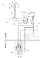
図1は、本実施形態に係るロボットアームを備えるロボットシステムの全体構成を示す概略図である。図1に示すように、ロボットシステム10は、爆発性雰囲気が存する第1領域で塗装作業を行うロボット20と、ロボット20が有する内圧防爆構造の周縁を画定する容器内に保護気体を供給して掃気を行うための掃気装置70と、ロボット20及び掃気装置70を制御するための制御装置90と、を備えている。 (Robot system 10)
FIG. 1 is a schematic diagram illustrating an overall configuration of a robot system including a robot arm according to the present embodiment. As shown in FIG. 1, therobot system 10 supplies a protective gas into a robot 20 that performs a painting operation in a first region where an explosive atmosphere exists, and a container that defines the peripheral edge of the internal pressure explosion-proof structure of the robot 20. A scavenging device 70 for scavenging and a control device 90 for controlling the robot 20 and the scavenging device 70 are provided.
図1は、本実施形態に係るロボットアームを備えるロボットシステムの全体構成を示す概略図である。図1に示すように、ロボットシステム10は、爆発性雰囲気が存する第1領域で塗装作業を行うロボット20と、ロボット20が有する内圧防爆構造の周縁を画定する容器内に保護気体を供給して掃気を行うための掃気装置70と、ロボット20及び掃気装置70を制御するための制御装置90と、を備えている。 (Robot system 10)
FIG. 1 is a schematic diagram illustrating an overall configuration of a robot system including a robot arm according to the present embodiment. As shown in FIG. 1, the
ロボットシステム10は、爆発性雰囲気が存する第1領域と、当該爆発性雰囲気が存しない第2領域とを仕切るための仕切部98をさらに備えている。そして、第1領域に後述する流量調節装置76、基台21、ロボットアーム30及びエンドエフェクタ50が設置されている。また、第2領域に後述する保護気体供給源71及び制御装置90が設置されている。
The robot system 10 further includes a partition unit 98 for partitioning the first region where the explosive atmosphere exists and the second region where the explosive atmosphere does not exist. A flow rate adjusting device 76, a base 21, a robot arm 30, and an end effector 50, which will be described later, are installed in the first region. Further, a protective gas supply source 71 and a control device 90 described later are installed in the second region.
本実施形態に係るロボット20は、自動車などに対して塗装を行うための塗装用ロボットとして構成されている。したがって、本実施形態において、上記第1領域は塗装場のことをいう。塗装場の雰囲気は、塗料に含まれる有機溶剤が気化したガスと混合され、可燃性ガス(又は爆発性ガス)になっていることが多い。このような第1領域で何ら対策を講じないまま電気機器を使用すると、通電により生じる火花などを原因に爆発が生じてしまう。
The robot 20 according to the present embodiment is configured as a painting robot for painting an automobile or the like. Therefore, in this embodiment, the said 1st area | region says the painting place. In many cases, the atmosphere of the paint shop is a combustible gas (or explosive gas) by mixing the gas containing the organic solvent contained in the paint. If an electric device is used without taking any measures in such a first region, an explosion occurs due to a spark generated by energization.
ロボット20は、その周縁の一部を画定する容器内に図示しないサーボモータなどの電気機器が多数設けられている。したがって、ロボット20に通電を行う前に、前記容器内に侵入している可燃性ガスを排除することを要する。そこで、掃気装置70を用いることで、前記容器内に保護気体を供給して掃気が行われる。
The robot 20 is provided with many electric devices such as a servo motor (not shown) in a container that defines a part of the periphery of the robot 20. Therefore, before energizing the robot 20, it is necessary to remove the combustible gas that has entered the container. Therefore, by using the scavenging device 70, scavenging is performed by supplying a protective gas into the container.
なお、基台21及びロボットアーム30の一部が前記容器を構成している。具体的には、基台21の内部空間とロボットアーム30の内部空間とは連通しており、ロボットアーム30の内部空間は、ロボットアーム30の基端部から第3関節軸JT3の部分まで延びている。
Note that the base 21 and a part of the robot arm 30 constitute the container. Specifically, the internal space of the base 21 and the internal space of the robot arm 30 communicate with each other, and the internal space of the robot arm 30 extends from the base end portion of the robot arm 30 to the portion of the third joint axis JT3. ing.
(ロボット20)
ロボット20は、基台21と、基台21に連結されるロボットアーム30と、ロボットアーム30の先端部に取り付けられるエンドエフェクタ50と、ロボットアーム30及びエンドエフェクタ50を制御して塗装作業を行わせるロボット制御装置60と、を有している。 (Robot 20)
Therobot 20 performs a painting operation by controlling the base 21, the robot arm 30 connected to the base 21, the end effector 50 attached to the tip of the robot arm 30, and the robot arm 30 and the end effector 50. And a robot control device 60.
ロボット20は、基台21と、基台21に連結されるロボットアーム30と、ロボットアーム30の先端部に取り付けられるエンドエフェクタ50と、ロボットアーム30及びエンドエフェクタ50を制御して塗装作業を行わせるロボット制御装置60と、を有している。 (Robot 20)
The
(ロボットアーム30)
ロボットアーム30は、7つの関節軸JT1~JT7と、これらの関節軸によって順次連結される6つのリンク31a~31fと、を有している。ロボットアーム30の関節軸JT1~JT7は、それぞれ、サーボモータによって回動可能に設けられている。 (Robot arm 30)
Therobot arm 30 has seven joint axes JT1 to JT7 and six links 31a to 31f sequentially connected by these joint axes. Each of the joint axes JT1 to JT7 of the robot arm 30 is rotatably provided by a servo motor.
ロボットアーム30は、7つの関節軸JT1~JT7と、これらの関節軸によって順次連結される6つのリンク31a~31fと、を有している。ロボットアーム30の関節軸JT1~JT7は、それぞれ、サーボモータによって回動可能に設けられている。 (Robot arm 30)
The
第1関節軸JT1は、サーボモータによって、第1リンク31aの先端部と第2リンク31bの基端部とを鉛直方向に延びる軸回りに回動可能に連結する。第2関節軸JT2は、サーボモータによって、第2リンク31bの先端部と第3リンク31cの基端部とを、水平方向に延びる軸回りにロボット20の前後方向と上下方向とが交わる平面において回動可能に連結する。
The first joint shaft JT1 is connected by a servo motor so that the distal end portion of the first link 31a and the proximal end portion of the second link 31b are rotatable about an axis extending in the vertical direction. The second joint axis JT2 is driven by a servo motor on the plane where the front-rear direction and the vertical direction of the robot 20 intersect the distal end portion of the second link 31b and the proximal end portion of the third link 31c around the axis extending in the horizontal direction. It is connected so that it can rotate.
第3関節軸JT3は、サーボモータによって、第3リンク31cの先端部と第4リンク31dの基端部とを、水平方向に延びる軸回りにロボット20の前後方向と上下方向とが交わる平面において回動可能に連結する。第4関節軸JT4は、サーボモータによって、第4リンクの先端部と第5リンク31eの基端部とを捻れ回動可能に連結する。
The third joint axis JT3 is driven by a servo motor on the plane where the front-rear direction and the vertical direction of the robot 20 intersect the distal end portion of the third link 31c and the proximal end portion of the fourth link 31d around the axis extending in the horizontal direction. It is connected so that it can rotate. The fourth joint shaft JT4 connects the distal end portion of the fourth link and the proximal end portion of the fifth link 31e so as to be twisted and rotated by a servo motor.
第5関節軸JT5は、サーボモータによって、第5リンク31eの先端部と第6リンク31fの基端部とを捻れ回動可能に連結する。第6関節軸JT6は、サーボモータによって、第6リンク31fの先端部とエンドエフェクタ50の基端部とを捻れ回動可能に連結する。第7関節軸JT7は、サーボモータによって、基台21と第1リンク31aの基端部とを、水平方向に延びる軸回りにロボット20の左右方向と上下方向とが交わる平面において回動可能に連結する。
The fifth joint shaft JT5 connects the distal end portion of the fifth link 31e and the proximal end portion of the sixth link 31f so as to be twisted and rotated by a servo motor. The sixth joint shaft JT6 connects the distal end portion of the sixth link 31f and the proximal end portion of the end effector 50 in a twistable manner by a servo motor. The seventh joint axis JT7 can be rotated by the servo motor between the base 21 and the base end portion of the first link 31a on a plane where the horizontal direction and the vertical direction of the robot 20 intersect about the axis extending in the horizontal direction. Link.
第1~3関節軸JT1~3及び第7関節軸JT7を回動させるためのサーボモータは、それぞれ、自らが回動させる関節軸に連結して設けられている。一方で、第4~6関節軸JT4~6を回動させるためのサーボモータは、それぞれ、自らが回動させる関節軸から離間して設けられている。具体的には、前記サーボモータは、それぞれ、第3関節軸JT3の近傍に互いに隣接して設けられており、配線を介して離間した関節軸を回動させている。そして、第1~7関節軸JT1~7を回動させるためのサーボモータは、それぞれ、容器内に設けられている。
Servo motors for rotating the first to third joint axes JT1 to JT3 and the seventh joint axis JT7 are respectively connected to the joint axes to be rotated by themselves. On the other hand, the servo motors for rotating the fourth to sixth joint axes JT4 to JT6 are provided separately from the joint axes to be rotated by themselves. Specifically, the servo motors are provided adjacent to each other in the vicinity of the third joint axis JT3, and rotate the joint axes that are separated from each other via wiring. Servo motors for rotating the first to seventh joint shafts JT1 to JT7 are respectively provided in the containers.
(エンドエフェクタ50)
本実施形態では、エンドエフェクタ50は、後述する複数の長尺状部材32に含まれる塗料供給用ホース(配管)から供給される塗料を自動車の車体などに吹き付けるための塗装ガンとして構成されている。なお、本実施形態では、塗装ガンはベル型塗装ガンとして構成されている。 (End effector 50)
In the present embodiment, theend effector 50 is configured as a coating gun for spraying paint supplied from a paint supply hose (piping) included in a plurality of long members 32 to be described later onto a vehicle body or the like. . In this embodiment, the painting gun is configured as a bell type painting gun.
本実施形態では、エンドエフェクタ50は、後述する複数の長尺状部材32に含まれる塗料供給用ホース(配管)から供給される塗料を自動車の車体などに吹き付けるための塗装ガンとして構成されている。なお、本実施形態では、塗装ガンはベル型塗装ガンとして構成されている。 (End effector 50)
In the present embodiment, the
(ロボット制御装置60)
ロボット制御装置60は、掃気制御装置80とともに制御装置90内に設けられている。ロボット制御装置60の具体的な構成は特に限定されないが、例えば、公知のプロセッサ(CPU等)が記憶部(メモリ)に格納されるプログラムに従って動作することにより実現される構成であってもよい。 (Robot control device 60)
Therobot control device 60 is provided in the control device 90 together with the scavenging control device 80. The specific configuration of the robot control device 60 is not particularly limited. For example, a configuration realized by a known processor (CPU or the like) operating according to a program stored in a storage unit (memory) may be used.
ロボット制御装置60は、掃気制御装置80とともに制御装置90内に設けられている。ロボット制御装置60の具体的な構成は特に限定されないが、例えば、公知のプロセッサ(CPU等)が記憶部(メモリ)に格納されるプログラムに従って動作することにより実現される構成であってもよい。 (Robot control device 60)
The
(掃気装置70)
掃気装置70は、保護気体供給源71と、保護気体供給源71から容器内まで保護気体を導くための供給流路72(流路)と、保護気体供給源71から容器内に供給される保護気体の流量を調節するための流量調節装置76と、流量調節装置76を制御して掃気を行うための掃気制御装置80と、を備えている。 (Scavenging device 70)
The scavengingdevice 70 includes a protective gas supply source 71, a supply flow path 72 (flow path) for guiding the protective gas from the protective gas supply source 71 into the container, and protection supplied from the protective gas supply source 71 into the container. A flow rate adjusting device 76 for adjusting the flow rate of gas and a scavenging control device 80 for controlling the flow rate adjusting device 76 to perform scavenging are provided.
掃気装置70は、保護気体供給源71と、保護気体供給源71から容器内まで保護気体を導くための供給流路72(流路)と、保護気体供給源71から容器内に供給される保護気体の流量を調節するための流量調節装置76と、流量調節装置76を制御して掃気を行うための掃気制御装置80と、を備えている。 (Scavenging device 70)
The scavenging
(保護気体供給源71)
保護気体供給源71は、第2領域に設けられている。本実施形態では、保護気体として空気を用いて掃気を行ってもよい。 (Protective gas supply source 71)
The protectivegas supply source 71 is provided in the second region. In the present embodiment, scavenging may be performed using air as the protective gas.
保護気体供給源71は、第2領域に設けられている。本実施形態では、保護気体として空気を用いて掃気を行ってもよい。 (Protective gas supply source 71)
The protective
(供給流路72)
図1に示すように、供給流路72は、第2領域に設けられる保護気体供給源71から第1領域に設けられるロボット20の容器内まで延びている。具体的には、供給流路72は、ロボット20の基台21に穿設された貫通孔を通って容器内挿入され、且つ、当該容器内の最深部(すなわち、第3関節軸JT3の部分)まで延びており、その先端部から保護気体が供給される。 (Supply channel 72)
As shown in FIG. 1, thesupply flow path 72 extends from the protective gas supply source 71 provided in the second region to the inside of the container of the robot 20 provided in the first region. Specifically, the supply flow path 72 is inserted into the container through a through hole formed in the base 21 of the robot 20, and the deepest part in the container (that is, a portion of the third joint axis JT3). ) And a protective gas is supplied from the tip.
図1に示すように、供給流路72は、第2領域に設けられる保護気体供給源71から第1領域に設けられるロボット20の容器内まで延びている。具体的には、供給流路72は、ロボット20の基台21に穿設された貫通孔を通って容器内挿入され、且つ、当該容器内の最深部(すなわち、第3関節軸JT3の部分)まで延びており、その先端部から保護気体が供給される。 (Supply channel 72)
As shown in FIG. 1, the
なお、供給流路72は、第2関節軸JT2を回動させるサーボモータまで延びる分岐路をさらに有しており、その先端部から保護気体が供給される。また、供給流路72は、第7関節軸JT7を回動させるサーボモータの近傍まで延びる分岐路をさらに有しており、その先端部からも保護気体が供給される。
Note that the supply flow path 72 further has a branch path extending to a servo motor that rotates the second joint shaft JT2, and a protective gas is supplied from the front end thereof. Further, the supply flow path 72 further has a branch path extending to the vicinity of the servo motor that rotates the seventh joint shaft JT7, and the protective gas is also supplied from the tip portion thereof.
(排出流路74)
容器内に供給された保護気体は、排出流路74によって容器から排出される。排出流路74は、基台21に穿設された貫通孔を通って容器の外部へと延びている。容器内の圧力は大気圧よりも高いため、供給流路72から容器内に供給された保護気体は、排出流路74の先端部に吸引されるようにして容器の外部へと排出される。 (Discharge flow path 74)
The protective gas supplied into the container is discharged from the container by thedischarge channel 74. The discharge channel 74 extends to the outside of the container through a through hole formed in the base 21. Since the pressure in the container is higher than the atmospheric pressure, the protective gas supplied from the supply flow path 72 into the container is discharged to the outside of the container so as to be sucked into the tip of the discharge flow path 74.
容器内に供給された保護気体は、排出流路74によって容器から排出される。排出流路74は、基台21に穿設された貫通孔を通って容器の外部へと延びている。容器内の圧力は大気圧よりも高いため、供給流路72から容器内に供給された保護気体は、排出流路74の先端部に吸引されるようにして容器の外部へと排出される。 (Discharge flow path 74)
The protective gas supplied into the container is discharged from the container by the
(流量調節装置76及び掃気制御装置80)
流量調節装置76は、供給流路72上に設けられる第1調節弁77と、排出流路74上に設けられる第2調節弁78と、を有している。また、掃気制御装置80は、ロボット制御装置60とともに制御装置90内に設けられている。掃気制御装置80の具体的な構成は特に限定されないが、例えば、ロボット制御装置60と同様に公知のプロセッサ(CPU等)が記憶部(メモリ)に格納されるプログラムに従って動作することにより実現される構成であってもよい。 (Flow control device 76 and scavenging control device 80)
The flowrate adjusting device 76 has a first control valve 77 provided on the supply flow path 72 and a second control valve 78 provided on the discharge flow path 74. The scavenging control device 80 is provided in the control device 90 together with the robot control device 60. The specific configuration of the scavenging control device 80 is not particularly limited. For example, as with the robot control device 60, a known processor (CPU or the like) is realized by operating according to a program stored in a storage unit (memory). It may be a configuration.
流量調節装置76は、供給流路72上に設けられる第1調節弁77と、排出流路74上に設けられる第2調節弁78と、を有している。また、掃気制御装置80は、ロボット制御装置60とともに制御装置90内に設けられている。掃気制御装置80の具体的な構成は特に限定されないが、例えば、ロボット制御装置60と同様に公知のプロセッサ(CPU等)が記憶部(メモリ)に格納されるプログラムに従って動作することにより実現される構成であってもよい。 (
The flow
(ロボットアーム30の要部構成)
本実施形態に係るロボットアーム30の要部構成について説明する。図2は、本実施形態に係るロボットアームの要部構成を示す一部断面概略図である。図2に示すように、本実施形態に係るロボットアーム30は、エンドエフェクタ50まで延びる複数の長尺状部材32と、複数の長尺状部材32の通路となる内部空間34の周縁を画定する筒状筐体36と、を備えている。また、ロボットアーム30は、筒状筐体36の先端部に対してエンドエフェクタ50を取り付けるために、筒状筐体36の内部空間34の先端に対して設けられる取り付け構造40をさらに備えている。なお、本実施形態では、内部空間34には、長尺状部材32に加えて後述する複数の固定部材42が配されている。 (Main part configuration of the robot arm 30)
The main configuration of therobot arm 30 according to this embodiment will be described. FIG. 2 is a partial cross-sectional schematic view showing the main configuration of the robot arm according to the present embodiment. As shown in FIG. 2, the robot arm 30 according to the present embodiment defines a plurality of elongated members 32 extending to the end effector 50 and a peripheral edge of an internal space 34 that serves as a passage for the plurality of elongated members 32. A cylindrical housing 36. Further, the robot arm 30 further includes an attachment structure 40 provided to the tip of the internal space 34 of the cylindrical housing 36 in order to attach the end effector 50 to the tip of the cylindrical housing 36. . In the present embodiment, in addition to the long member 32, a plurality of fixing members 42 described later are arranged in the internal space 34.
本実施形態に係るロボットアーム30の要部構成について説明する。図2は、本実施形態に係るロボットアームの要部構成を示す一部断面概略図である。図2に示すように、本実施形態に係るロボットアーム30は、エンドエフェクタ50まで延びる複数の長尺状部材32と、複数の長尺状部材32の通路となる内部空間34の周縁を画定する筒状筐体36と、を備えている。また、ロボットアーム30は、筒状筐体36の先端部に対してエンドエフェクタ50を取り付けるために、筒状筐体36の内部空間34の先端に対して設けられる取り付け構造40をさらに備えている。なお、本実施形態では、内部空間34には、長尺状部材32に加えて後述する複数の固定部材42が配されている。 (Main part configuration of the robot arm 30)
The main configuration of the
(複数の長尺状部材32)
複数の長尺状部材32は、それぞれ、配線又は配管として構成されている。本実施形態では、複数の長尺状部材32は、エンドエフェクタ50に接続される電気配線(配線)と、塗料供給用ホース(配管)とを有している。なお、複数の長尺状部材32は、それぞれ、小型化が図られていないロボットアームに備えられる同様の部材と比較して、径寸法が小さく形成されていてもよい。これにより、ロボットアームの小型化を図ることが容易となる。 (Several elongated members 32)
Each of the plurality oflong members 32 is configured as a wiring or a pipe. In the present embodiment, the plurality of elongate members 32 have electrical wiring (wiring) connected to the end effector 50 and paint supply hose (piping). Each of the plurality of long members 32 may be formed with a smaller diameter than a similar member provided in a robot arm that is not downsized. Thereby, it becomes easy to reduce the size of the robot arm.
複数の長尺状部材32は、それぞれ、配線又は配管として構成されている。本実施形態では、複数の長尺状部材32は、エンドエフェクタ50に接続される電気配線(配線)と、塗料供給用ホース(配管)とを有している。なお、複数の長尺状部材32は、それぞれ、小型化が図られていないロボットアームに備えられる同様の部材と比較して、径寸法が小さく形成されていてもよい。これにより、ロボットアームの小型化を図ることが容易となる。 (Several elongated members 32)
Each of the plurality of
(筒状筐体36)
本実施形態では、ロボットアーム30の第4関節軸JT4から先端までが筒状筐体36を構成している。なお、複数の長尺状部材32は、第4関節軸JT4よりも基端側において、ロボットアーム30の外面に沿うように露出して配されていてもよい。これにより、複数の長尺状部材32のメンテナンス性等を向上させることができる。 (Cylindrical housing 36)
In the present embodiment, the fourth armature axis JT4 to the tip of therobot arm 30 constitutes a cylindrical housing 36. Note that the plurality of elongated members 32 may be arranged so as to be exposed along the outer surface of the robot arm 30 on the proximal end side with respect to the fourth joint axis JT4. Thereby, the maintainability etc. of the some elongate member 32 can be improved.
本実施形態では、ロボットアーム30の第4関節軸JT4から先端までが筒状筐体36を構成している。なお、複数の長尺状部材32は、第4関節軸JT4よりも基端側において、ロボットアーム30の外面に沿うように露出して配されていてもよい。これにより、複数の長尺状部材32のメンテナンス性等を向上させることができる。 (Cylindrical housing 36)
In the present embodiment, the fourth armature axis JT4 to the tip of the
筒状筐体36は、先端部の内径が基端部の内径よりも大きく形成されている。本実施形態では、筒状筐体36は、その軸方向において、第6関節軸JT6(複数の関節軸のうちで最も先端側に設けられる関節軸)と第5関節軸JT5(その一つ基端側に設けられる関節軸)との間に、先端部に向かうに連れて内径が大きくなる内径拡張部37を有している。
The cylindrical housing 36 is formed such that the inner diameter of the distal end portion is larger than the inner diameter of the proximal end portion. In the present embodiment, the cylindrical housing 36 has a sixth joint axis JT6 (joint axis provided on the most distal side among the plurality of joint axes) and a fifth joint axis JT5 (one of them) in the axial direction. An inner diameter expansion portion 37 having an inner diameter that increases toward the distal end portion is provided between the joint shaft and the joint shaft provided on the end side.
なお、筒状筐体36は、その軸方向において、基端部(すなわち、内径拡張部37よりも基端側の部分)の内径が一定であってもよい。当該内径は、例えば、50cm程度であってもよい。また、筒状筐体36は、その軸方向において、先端部(すなわち、内径拡張部37よりも先端側の部分)の内径が一定であってもよい。当該内径は、例えば、70cm程度であってもよい。
In addition, the cylindrical housing 36 may have a constant inner diameter at the base end portion (that is, a portion closer to the base end side than the inner diameter expansion portion 37) in the axial direction. The inner diameter may be about 50 cm, for example. Further, the cylindrical housing 36 may have a constant inner diameter at the distal end portion (that is, the portion on the distal end side with respect to the inner diameter expanding portion 37) in the axial direction. The inner diameter may be about 70 cm, for example.
(取り付け構造40)
取り付け構造40は、複数の長尺状部材32それぞれを挿通するために当該複数の長尺状部材32それぞれに対応して穿設されている挿通孔44と、複数の長尺状部材32それぞれを挿通孔44に対して固定するための固定部材42と、を有している。固定部材42は、例えば、エンドエフェクタ50の側から複数の長尺状部材32を囲繞するように取り付けられる6角ナット等であってもよい。すなわち、筒状筐体36の軸方向に見て、固定部材42の径寸法は、複数の長尺状部材32の径寸法よりも大きい。 (Mounting structure 40)
Theattachment structure 40 includes an insertion hole 44 formed corresponding to each of the plurality of long members 32 in order to insert each of the plurality of long members 32, and each of the plurality of long members 32. And a fixing member 42 for fixing to the insertion hole 44. The fixing member 42 may be, for example, a hexagonal nut attached so as to surround the plurality of long members 32 from the end effector 50 side. That is, the radial dimension of the fixing member 42 is larger than the radial dimension of the plurality of long members 32 when viewed in the axial direction of the cylindrical housing 36.
取り付け構造40は、複数の長尺状部材32それぞれを挿通するために当該複数の長尺状部材32それぞれに対応して穿設されている挿通孔44と、複数の長尺状部材32それぞれを挿通孔44に対して固定するための固定部材42と、を有している。固定部材42は、例えば、エンドエフェクタ50の側から複数の長尺状部材32を囲繞するように取り付けられる6角ナット等であってもよい。すなわち、筒状筐体36の軸方向に見て、固定部材42の径寸法は、複数の長尺状部材32の径寸法よりも大きい。 (Mounting structure 40)
The
(効果)
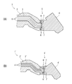
本実施形態に係るロボットアーム30は、上記構成を備えることで、小型化を図りながら、内部に挿通される複数の長尺状部材32の損傷を抑制することが可能となる。当該効果について、図3に基づき詳細に説明する。図3は、ロボットアームの小型化を図るときに生じ得る問題を説明するためのロボットアームの一部及びその先端部に取り付けられるエンドエフェクタの概略図である。(A)に、従来の第1態様に係るロボットアーム及びその先端部に取り付けられるエンドエフェクタの概略図を示し、(B)に、従来の第2態様に係るロボットアーム及びその先端部に取り付けられるエンドエフェクタの概略図を示している。 (effect)
Therobot arm 30 according to the present embodiment is provided with the above-described configuration, so that it is possible to suppress damage to the plurality of long members 32 inserted therein while achieving downsizing. The effect will be described in detail with reference to FIG. FIG. 3 is a schematic view of a part of the robot arm and an end effector attached to the tip of the robot arm for explaining problems that may occur when the robot arm is downsized. (A) shows a schematic diagram of a robot arm according to the conventional first aspect and an end effector attached to the tip thereof, and (B) shows a robot arm according to the conventional second aspect and attached to the tip thereof. Fig. 3 shows a schematic diagram of an end effector.
本実施形態に係るロボットアーム30は、上記構成を備えることで、小型化を図りながら、内部に挿通される複数の長尺状部材32の損傷を抑制することが可能となる。当該効果について、図3に基づき詳細に説明する。図3は、ロボットアームの小型化を図るときに生じ得る問題を説明するためのロボットアームの一部及びその先端部に取り付けられるエンドエフェクタの概略図である。(A)に、従来の第1態様に係るロボットアーム及びその先端部に取り付けられるエンドエフェクタの概略図を示し、(B)に、従来の第2態様に係るロボットアーム及びその先端部に取り付けられるエンドエフェクタの概略図を示している。 (effect)
The
図3(A)に示すように、従来の第1態様に係るロボットアーム1の先端部には、エンドエフェクタ4を取り付けるための取り付け構造5が設けられている。取り付け構造5は、複数の長尺状部材8それぞれを挿通するために当該複数の長尺状部材8それぞれに対応して穿設されている挿通孔7と、複数の長尺状部材8それぞれを挿通孔7に対して固定するための固定部材6と、を有している。
3A, an attachment structure 5 for attaching the end effector 4 is provided at the tip of the robot arm 1 according to the conventional first aspect. The attachment structure 5 includes an insertion hole 7 drilled corresponding to each of the plurality of long members 8 in order to insert each of the plurality of long members 8, and each of the plurality of long members 8. And a fixing member 6 for fixing to the insertion hole 7.
図3(B)に示すように、従来の第2態様に係るロボットアーム1´は、筒状筐体2´及びその内部空間3が小さく形成される。しかし、このとき、取り付け構造5´は、固定部材6´の径寸法を小さくすることが困難であるため、その要部構造を小型化することが難しい。ところが、上記従来の第1態様が備える取り付け構造5のままでは、複数の長尺状部材8´は、それぞれ、筒状筐体2´の内部空間から取り付け構造5´の挿通孔7´に至るまでに、筒状筐体2´の径方向の外側に向けて急激に屈曲してしまう。このように屈曲することで、複数の長尺状部材8´それぞれが損傷してしまう。
As shown in FIG. 3 (B), the robot arm 1 'according to the second aspect of the prior art has a cylindrical housing 2' and an internal space 3 formed small. However, at this time, since it is difficult for the mounting structure 5 ′ to reduce the diameter of the fixing member 6 ′, it is difficult to reduce the size of the main structure. However, with the mounting structure 5 included in the first conventional aspect, the plurality of long members 8 ′ each reach the insertion hole 7 ′ of the mounting structure 5 ′ from the internal space of the cylindrical housing 2 ′. By the time, it will be bent rapidly toward the outer side in the radial direction of the cylindrical casing 2 ′. By bending in this way, each of the plurality of long members 8 ′ is damaged.
そこで、図3(B)に示すように、筒状筐体2´と取り付け構造5´との間にスペーサーを設け、当該スペーサー内で複数の長尺状部材8´それぞれを緩やかに屈曲させてから取り付け構造5´に至らせることで、複数の長尺状部材8´の損傷を抑制することが考えられる。しかし、このようにスペーサーを設けることは、ロボットアーム1´の小型化を図るという目的に反してしまう。また、スペーサーが妨げとなって、ロボットアーム1´に所望する姿勢をとらせることが困難になってしまう。
Therefore, as shown in FIG. 3B, a spacer is provided between the cylindrical housing 2 ′ and the mounting structure 5 ′, and each of the plurality of long members 8 ′ is gently bent in the spacer. It can be considered that the damage to the plurality of long members 8 ′ is suppressed by reaching the mounting structure 5 ′ from the top. However, providing the spacer in this way is contrary to the purpose of reducing the size of the robot arm 1 '. Moreover, it becomes difficult for the robot arm 1 'to take a desired posture because the spacer is obstructed.
一方、本実施形態に係るロボットアーム30は、先端部の内径が基端部の内径よりも大きく形成されている。これにより、複数の長尺状部材32は、それぞれ、筒状筐体36の内部空間34から取り付け構造40の挿通孔44に至るまでに、筒状筐体36の径方向の外側に向けて急激に屈曲することがない。また、前記先端部以外の箇所では内径が小さいので小型化を図ることができる。その結果、本発明に係るロボットアーム30は、小型化を図りながら、内部に挿通される複数の長尺状部材32の損傷を抑制することが可能となる。
On the other hand, the robot arm 30 according to the present embodiment is formed such that the inner diameter of the distal end portion is larger than the inner diameter of the proximal end portion. As a result, each of the plurality of long members 32 is abruptly directed outwardly in the radial direction of the cylindrical casing 36 from the internal space 34 of the cylindrical casing 36 to the insertion hole 44 of the mounting structure 40. There is no bending. Further, since the inner diameter is small at a place other than the tip, the size can be reduced. As a result, the robot arm 30 according to the present invention can suppress damage to the plurality of long members 32 inserted therein while reducing the size.
また、本実施形態では、筒状筐体36は、先端部と基端部との間に先端部に向かうに連れて内径が大きくなる内径拡張部37を有しているので、筒状筐体36の内部で複数の長尺状部材32を緩やかに屈曲させることが可能となる。これにより、複数の長尺状部材32が損傷してしまうことをいっそう抑制することができる。
In the present embodiment, the cylindrical housing 36 includes the inner diameter expansion portion 37 whose inner diameter increases toward the distal end portion between the distal end portion and the proximal end portion. A plurality of elongated members 32 can be gently bent inside 36. Thereby, it can suppress further that the some elongate member 32 will be damaged.
さらに、本実施形態では、筒状筐体36は、その軸方向において、第6関節軸JT6と第5関節軸JT5との間に、内径拡張部37を有しているので、出来得る限り小型化を図りながら、複数の長尺状部材32の損傷を抑制することが可能となる。
Furthermore, in the present embodiment, the cylindrical housing 36 has the inner diameter expansion portion 37 between the sixth joint axis JT6 and the fifth joint axis JT5 in the axial direction thereof, so that it is as small as possible. It is possible to suppress damage to the plurality of long members 32 while achieving the reduction.
そして、本実施形態に係るロボットアーム30が上記効果を奏するので、ひいては、それを備えるロボット20は、小型化を図りながら、内部に挿通される複数の長尺状部材32の損傷を抑制することが可能となる。
And since the robot arm 30 which concerns on this embodiment has the said effect, by extension, the robot 20 provided with it suppresses the damage of the some elongate member 32 penetrated inside, aiming at size reduction. Is possible.
(変形例)
上記説明から、当業者にとっては、本発明の多くの改良や他の実施形態が明らかである。したがって、上記説明は、例示としてのみ解釈されるべきであり、本発明を実行する最良の態様を当業者に教示する目的で提供されたものである。本発明の精神を逸脱することなく、その構造及び/又は機能の詳細を実質的に変更できる。 (Modification)
From the above description, many modifications and other embodiments of the present invention are obvious to one skilled in the art. Accordingly, the foregoing description should be construed as illustrative only and is provided for the purpose of teaching those skilled in the art the best mode of carrying out the invention. The details of the structure and / or function may be substantially changed without departing from the spirit of the invention.
上記実施形態では、ロボット20が塗装用ロボットとして構成されている場合を説明したが、これに限定されない。例えば、ロボット20は、ワークを搬送するための搬送用ロボットとして構成されていてもよいし、その他のロボットとして構成されていてもよい。
In the above embodiment, the case where the robot 20 is configured as a painting robot has been described. However, the present invention is not limited to this. For example, the robot 20 may be configured as a transfer robot for transferring a workpiece, or may be configured as another robot.
上記実施形態では、エンドエフェクタ50がベル型塗装ガンとして構成されている場合を説明したが、これに限定されない。例えば、エンドエフェクタ50は、単純なスプレー式の塗装ガンであってもよいし、或いは、その他の塗装ガンであってもよい。また、ロボット20が塗装用ロボット以外のロボットとして構成されている場合、エンドエフェクタ50は、塗装ガン以外のエンドエフェクタ(例えば、ワークを保持するための保持部を有しているエンドエフェクタ)として構成されていてもよい。
In the above embodiment, the case where the end effector 50 is configured as a bell-type paint gun has been described. However, the present invention is not limited to this. For example, the end effector 50 may be a simple spray paint gun, or may be another paint gun. When the robot 20 is configured as a robot other than the painting robot, the end effector 50 is configured as an end effector other than the coating gun (for example, an end effector having a holding unit for holding a workpiece). May be.
上記実施形態では、複数の長尺状部材32は、エンドエフェクタ50に接続される電気配線(配線)と、塗料供給用ホース(配管)とを有している場合について説明したが、これに限定されない。例えば、複数の長尺状部材32は、その全てが電気配線であってもよいし、又は、その全てが塗料供給用ホースであってもよい。これらどちらかの場合、例えば、筒状筐体36の内部空間34に挿通されない長尺状部材は筒状筐体36の外部に露出してエンドエフェクタ50まで延びてもよい。さらに、例えば、複数の長尺状部材32は、ロボット20が塗装用ロボット以外のロボットとして構成されている場合、塗料供給用ホース以外の配管を有していてもよい。
In the above-described embodiment, the case where the plurality of long members 32 have the electrical wiring (wiring) connected to the end effector 50 and the paint supply hose (piping) has been described, but the present invention is not limited thereto. Not. For example, all of the plurality of elongated members 32 may be electric wirings, or all of them may be paint supply hoses. In either case, for example, a long member that is not inserted into the internal space 34 of the cylindrical housing 36 may be exposed to the outside of the cylindrical housing 36 and extend to the end effector 50. Further, for example, when the robot 20 is configured as a robot other than the painting robot, the plurality of long members 32 may have piping other than the paint supply hose.
上記実施形態では、内径拡張部37は、筒状筐体36の軸方向において、第6関節軸JT6と第5関節軸JT5との間に設けられる場合について説明したが、この場合に限定されず、他の箇所に設けられていてもよい。なお、筒状筐体36は、その軸方向の基端から先端の全域に亘って、基端から先端に向かうにつれて径寸法が大きくなるように形成されていてもよい。換言すれば、筒状筐体36全体が内径拡張部37として構成されていてもよい。
In the above embodiment, the case where the inner diameter expansion portion 37 is provided between the sixth joint axis JT6 and the fifth joint axis JT5 in the axial direction of the cylindrical housing 36 has been described. However, the present invention is not limited to this case. , May be provided at other locations. The cylindrical housing 36 may be formed so that the diameter dimension increases from the proximal end to the distal end over the entire region from the axial proximal end to the distal end. In other words, the entire cylindrical housing 36 may be configured as the inner diameter expansion portion 37.
また、図示するように、上記実施形態に係る内径拡張部37は、断面図を側面視したとき、その内面が直線状であったが、階段状であってもよいし、或いは、その他の形状であってもよい。なお、内径拡張部37は、その内面に1つ以上の凹部が形成されることで、筒状筐体36の先端部に向かうに連れて断続的に内径が大きくなる構造であってもよい。
Moreover, as shown in the drawing, the inner diameter expansion portion 37 according to the above embodiment has a linear inner surface when viewed from the side, but may have a stepped shape or other shapes. It may be. Note that the inner diameter expansion portion 37 may have a structure in which the inner diameter is intermittently increased toward the distal end portion of the cylindrical housing 36 by forming one or more concave portions on the inner surface.
さらに、内径拡張部37は、筒状筐体36の先端部に向かうに連れて内径が大きくなる態様に限定されず、筒状筐体36の軸方向における一カ所で内径が大きくなる構造であってもよい。
Further, the inner diameter expansion portion 37 is not limited to an aspect in which the inner diameter increases toward the distal end portion of the cylindrical casing 36, and has a structure in which the inner diameter increases at one place in the axial direction of the cylindrical casing 36. May be.
1 ロボットアーム
2 筒状筐体
3 内部空間
4 エンドエフェクタ
5 取り付け構造
6 固定部材
7 挿通孔
8 複数の長尺状部材
10 ロボットシステム
20 ロボット
21 基台
30 ロボットアーム
31 リンク
32 複数の長尺状部材
34 内部空間
36 筒状筐体
37 内径拡張部
40 取り付け構造
42 固定部材
44 挿通孔
50 エンドエフェクタ
60 ロボット制御装置
70 掃気装置
71 保護気体供給源
72 供給流路
74 排出流路
76 流量調節装置
77 第1調整弁
78 第2調整弁
80 掃気制御装置
90 制御装置
98 仕切部 DESCRIPTION OFSYMBOLS 1 Robot arm 2 Cylindrical housing 3 Internal space 4 End effector 5 Mounting structure 6 Fixing member 7 Insertion hole 8 Plural long members 10 Robot system 20 Robot 21 Base 30 Robot arm 31 Link 32 Plural long members 34 Internal space 36 Cylindrical housing 37 Inner diameter expansion portion 40 Mounting structure 42 Fixing member 44 Insertion hole 50 End effector 60 Robot control device 70 Scavenging device 71 Protective gas supply source 72 Supply flow channel 74 Discharge flow channel 76 Flow rate adjustment device 77 1 adjustment valve 78 2nd adjustment valve 80 Scavenging control device 90 control device 98 partition part
2 筒状筐体
3 内部空間
4 エンドエフェクタ
5 取り付け構造
6 固定部材
7 挿通孔
8 複数の長尺状部材
10 ロボットシステム
20 ロボット
21 基台
30 ロボットアーム
31 リンク
32 複数の長尺状部材
34 内部空間
36 筒状筐体
37 内径拡張部
40 取り付け構造
42 固定部材
44 挿通孔
50 エンドエフェクタ
60 ロボット制御装置
70 掃気装置
71 保護気体供給源
72 供給流路
74 排出流路
76 流量調節装置
77 第1調整弁
78 第2調整弁
80 掃気制御装置
90 制御装置
98 仕切部 DESCRIPTION OF
Claims (8)
- エンドエフェクタが取り付けられるロボットアームであって、
前記エンドエフェクタまで延びる複数の長尺状部材と、
前記複数の長尺状部材の通路となる内部空間の周縁を画定する筒状筐体と、
前記筒状筐体の先端部に対して前記エンドエフェクタを取り付けるために、前記筒状筐体の内部空間の先端に対して設けられる取り付け構造と、を備えており、
前記取り付け構造は、
前記複数の長尺状部材それぞれを挿通するために前記複数の長尺状部材それぞれに対応して穿設されている挿通孔と、
前記複数の長尺状部材それぞれを前記挿通孔に対して固定するための固定部材と、を有しており、
前記筒状筐体は、先端部の内径が基端部の内径よりも大きく形成されていることを特徴とする、ロボットアーム。 A robot arm to which an end effector is attached,
A plurality of elongated members extending to the end effector;
A cylindrical housing that defines a peripheral edge of the internal space serving as a passage for the plurality of elongated members;
In order to attach the end effector to the distal end portion of the cylindrical casing, the mounting structure is provided to the distal end of the internal space of the cylindrical casing, and
The mounting structure is
An insertion hole that is drilled corresponding to each of the plurality of elongate members in order to insert each of the plurality of elongate members;
A fixing member for fixing each of the plurality of elongated members to the insertion hole,
The robot arm according to claim 1, wherein the cylindrical casing is formed such that an inner diameter of a distal end portion is larger than an inner diameter of a proximal end portion. - 前記複数の長尺状部材は、それぞれ、配線又は配管として構成されている、請求項1に記載のロボットアーム。 The robot arm according to claim 1, wherein each of the plurality of long members is configured as wiring or piping.
- 前記筒状筐体は、前記先端部と前記基端部との間に前記先端部に向かうに連れて内径が大きくなる内径拡張部を有している、請求項1又は2に記載のロボットアーム。 3. The robot arm according to claim 1, wherein the cylindrical casing has an inner diameter expansion portion between the distal end portion and the proximal end portion, and an inner diameter expanding portion that increases toward the distal end portion. .
- 前記筒状筐体には複数の関節軸が設けられており、
前記内径拡張部は、前記筒状筐体の軸方向において前記複数の関節軸のうちで最も先端側に設けられる関節軸とその一つ基端側に設けられる関節軸との間に存している、請求項3に記載のロボットアーム。 The cylindrical housing is provided with a plurality of joint axes,
The inner diameter expansion portion is located between a joint shaft provided on the most distal side of the plurality of joint shafts in the axial direction of the cylindrical housing and a joint shaft provided on one proximal end side thereof. The robot arm according to claim 3. - 請求項1乃至4のいずれかに記載のロボットアームと、前記ロボットアームに取り付けられるエンドエフェクタと、を備えていることを特徴とする、ロボット。 A robot comprising the robot arm according to any one of claims 1 to 4 and an end effector attached to the robot arm.
- 塗装作業を行うための塗装用ロボットとして構成されている、請求項5に記載のロボット。 The robot according to claim 5, wherein the robot is configured as a painting robot for performing painting work.
- 前記エンドエフェクタは塗装ガンとして構成されている、請求項6に記載のロボット。 The robot according to claim 6, wherein the end effector is configured as a paint gun.
- 前記塗装ガンはベル型塗装ガンとして構成されている、請求項7に記載のロボット。 The robot according to claim 7, wherein the paint gun is configured as a bell-type paint gun.
Priority Applications (5)
| Application Number | Priority Date | Filing Date | Title |
|---|---|---|---|
| EP19811240.1A EP3804921A4 (en) | 2018-05-31 | 2019-05-30 | Robot arm and robot provided with same |
| KR1020237002746A KR20230021151A (en) | 2018-05-31 | 2019-05-30 | Robot arm and robot including the same |
| CN201980034879.2A CN112166014B (en) | 2018-05-31 | 2019-05-30 | Robot arm and robot provided with same |
| KR1020207035970A KR20210010531A (en) | 2018-05-31 | 2019-05-30 | Robot arm and robot equipped with it |
| US17/059,541 US11745357B2 (en) | 2018-05-31 | 2019-05-30 | Robotic arm and robot having the same |
Applications Claiming Priority (2)
| Application Number | Priority Date | Filing Date | Title |
|---|---|---|---|
| JP2018104976A JP7121546B2 (en) | 2018-05-31 | 2018-05-31 | ROBOT ARM AND ROBOT INCLUDING THE SAME |
| JP2018-104976 | 2018-05-31 |
Publications (1)
| Publication Number | Publication Date |
|---|---|
| WO2019230896A1 true WO2019230896A1 (en) | 2019-12-05 |
Family
ID=68697564
Family Applications (1)
| Application Number | Title | Priority Date | Filing Date |
|---|---|---|---|
| PCT/JP2019/021561 WO2019230896A1 (en) | 2018-05-31 | 2019-05-30 | Robot arm and robot provided with same |
Country Status (6)
| Country | Link |
|---|---|
| US (1) | US11745357B2 (en) |
| EP (1) | EP3804921A4 (en) |
| JP (1) | JP7121546B2 (en) |
| KR (2) | KR20230021151A (en) |
| CN (1) | CN112166014B (en) |
| WO (1) | WO2019230896A1 (en) |
Families Citing this family (2)
| Publication number | Priority date | Publication date | Assignee | Title |
|---|---|---|---|---|
| JP2022091409A (en) * | 2020-12-09 | 2022-06-21 | 株式会社安川電機 | Robot system |
| DE102022100608A1 (en) | 2022-01-12 | 2023-07-13 | Dürr Systems Ag | Robot hand, in particular for carrying an application device |
Citations (7)
| Publication number | Priority date | Publication date | Assignee | Title |
|---|---|---|---|---|
| JP2000158377A (en) * | 1998-11-30 | 2000-06-13 | Tokico Ltd | Painting robot |
| JP2002079487A (en) * | 2000-09-05 | 2002-03-19 | Nachi Fujikoshi Corp | Wrist device for industrial robot |
| JP2005096073A (en) * | 2001-10-22 | 2005-04-14 | Yaskawa Electric Corp | Industrial robot |
| JP2005279635A (en) * | 2004-03-03 | 2005-10-13 | Toyota Motor Corp | Electrostatic coating machine for coating robot |
| US20060104792A1 (en) * | 2001-08-16 | 2006-05-18 | Stefano Giuliano | Manipulator with a line arrangement leading to the processing tool |
| JP2015016523A (en) | 2013-07-10 | 2015-01-29 | ファナック株式会社 | Wrist structure part of industrial robot |
| JP2017507799A (en) * | 2014-03-18 | 2017-03-23 | デュール システムズ アーゲーDurr Systems AG | Robot assembly and corresponding assembly method |
Family Cites Families (3)
| Publication number | Priority date | Publication date | Assignee | Title |
|---|---|---|---|---|
| EP2679351A1 (en) | 2003-06-26 | 2014-01-01 | Abb As | Robot wrist |
| US20050194474A1 (en) * | 2004-03-03 | 2005-09-08 | Ransburg Industrial Finishing K.K. | Electrostatic atomizer for a painting robot |
| JP6184161B2 (en) * | 2012-07-12 | 2017-08-23 | キヤノン株式会社 | robot |
-
2018
- 2018-05-31 JP JP2018104976A patent/JP7121546B2/en active Active
-
2019
- 2019-05-30 EP EP19811240.1A patent/EP3804921A4/en active Pending
- 2019-05-30 KR KR1020237002746A patent/KR20230021151A/en not_active Application Discontinuation
- 2019-05-30 KR KR1020207035970A patent/KR20210010531A/en not_active Application Discontinuation
- 2019-05-30 WO PCT/JP2019/021561 patent/WO2019230896A1/en unknown
- 2019-05-30 CN CN201980034879.2A patent/CN112166014B/en active Active
- 2019-05-30 US US17/059,541 patent/US11745357B2/en active Active
Patent Citations (7)
| Publication number | Priority date | Publication date | Assignee | Title |
|---|---|---|---|---|
| JP2000158377A (en) * | 1998-11-30 | 2000-06-13 | Tokico Ltd | Painting robot |
| JP2002079487A (en) * | 2000-09-05 | 2002-03-19 | Nachi Fujikoshi Corp | Wrist device for industrial robot |
| US20060104792A1 (en) * | 2001-08-16 | 2006-05-18 | Stefano Giuliano | Manipulator with a line arrangement leading to the processing tool |
| JP2005096073A (en) * | 2001-10-22 | 2005-04-14 | Yaskawa Electric Corp | Industrial robot |
| JP2005279635A (en) * | 2004-03-03 | 2005-10-13 | Toyota Motor Corp | Electrostatic coating machine for coating robot |
| JP2015016523A (en) | 2013-07-10 | 2015-01-29 | ファナック株式会社 | Wrist structure part of industrial robot |
| JP2017507799A (en) * | 2014-03-18 | 2017-03-23 | デュール システムズ アーゲーDurr Systems AG | Robot assembly and corresponding assembly method |
Also Published As
| Publication number | Publication date |
|---|---|
| EP3804921A4 (en) | 2022-03-30 |
| CN112166014A (en) | 2021-01-01 |
| JP7121546B2 (en) | 2022-08-18 |
| EP3804921A1 (en) | 2021-04-14 |
| KR20210010531A (en) | 2021-01-27 |
| US11745357B2 (en) | 2023-09-05 |
| CN112166014B (en) | 2023-11-14 |
| JP2019209396A (en) | 2019-12-12 |
| US20210206000A1 (en) | 2021-07-08 |
| KR20230021151A (en) | 2023-02-13 |
Similar Documents
| Publication | Publication Date | Title |
|---|---|---|
| JP4822061B2 (en) | Double arm robot | |
| US7765890B2 (en) | Industrial robot | |
| JP6670455B2 (en) | Robots and robot systems | |
| JP4038217B2 (en) | Striated structure of industrial robot | |
| US9346174B2 (en) | Umbilical member arrangement structure of industrial robot having hollow member | |
| WO2019230896A1 (en) | Robot arm and robot provided with same | |
| JP5004020B2 (en) | Articulated manipulator and robot system | |
| EP1938930B1 (en) | Industrial robot with tubular member for a cable harness | |
| EP2772337B1 (en) | Multi-axis robot | |
| US20160023360A1 (en) | Robot | |
| WO2003037577A1 (en) | Industrial robot | |
| JP2008073833A (en) | Drive mechanism for industrial robot arm | |
| JP2009113188A (en) | Work robot | |
| CN111195899B (en) | Robot | |
| US20160023358A1 (en) | Robot | |
| WO2021005968A1 (en) | Suspended industrial robot | |
| JP4817132B2 (en) | Internal pressure explosion-proof robot and internal pressure explosion-proof system provided with the same | |
| JP2004090135A (en) | Joint structure of robot | |
| JPH10166292A (en) | Wrist structure for vertically articulated robot | |
| JP5135925B2 (en) | robot | |
| JP2003159689A (en) | Arm device for industrial robot having hollow hole wrist | |
| EP3002091A1 (en) | Robot | |
| JP2007125651A (en) | Industrial robot | |
| JP2008023680A (en) | Robot arm bracket and robot arm | |
| JP2003025270A (en) | Treatment device for wiring/piping for industrial robot |
Legal Events
| Date | Code | Title | Description |
|---|---|---|---|
| 121 | Ep: the epo has been informed by wipo that ep was designated in this application |
Ref document number: 19811240 Country of ref document: EP Kind code of ref document: A1 |
|
| NENP | Non-entry into the national phase |
Ref country code: DE |
|
| ENP | Entry into the national phase |
Ref document number: 20207035970 Country of ref document: KR Kind code of ref document: A |
|
| ENP | Entry into the national phase |
Ref document number: 2019811240 Country of ref document: EP Effective date: 20210111 |