WO2019230380A1 - 表示装置および加湿処理装置 - Google Patents
表示装置および加湿処理装置 Download PDFInfo
- Publication number
- WO2019230380A1 WO2019230380A1 PCT/JP2019/019184 JP2019019184W WO2019230380A1 WO 2019230380 A1 WO2019230380 A1 WO 2019230380A1 JP 2019019184 W JP2019019184 W JP 2019019184W WO 2019230380 A1 WO2019230380 A1 WO 2019230380A1
- Authority
- WO
- WIPO (PCT)
- Prior art keywords
- region
- display device
- substrate
- housing
- display panel
- Prior art date
- Legal status (The legal status is an assumption and is not a legal conclusion. Google has not performed a legal analysis and makes no representation as to the accuracy of the status listed.)
- Ceased
Links
Images





Classifications
-
- G—PHYSICS
- G02—OPTICS
- G02F—OPTICAL DEVICES OR ARRANGEMENTS FOR THE CONTROL OF LIGHT BY MODIFICATION OF THE OPTICAL PROPERTIES OF THE MEDIA OF THE ELEMENTS INVOLVED THEREIN; NON-LINEAR OPTICS; FREQUENCY-CHANGING OF LIGHT; OPTICAL LOGIC ELEMENTS; OPTICAL ANALOGUE/DIGITAL CONVERTERS
- G02F1/00—Devices or arrangements for the control of the intensity, colour, phase, polarisation or direction of light arriving from an independent light source, e.g. switching, gating or modulating; Non-linear optics
- G02F1/01—Devices or arrangements for the control of the intensity, colour, phase, polarisation or direction of light arriving from an independent light source, e.g. switching, gating or modulating; Non-linear optics for the control of the intensity, phase, polarisation or colour
- G02F1/13—Devices or arrangements for the control of the intensity, colour, phase, polarisation or direction of light arriving from an independent light source, e.g. switching, gating or modulating; Non-linear optics for the control of the intensity, phase, polarisation or colour based on liquid crystals, e.g. single liquid crystal display cells
- G02F1/133—Constructional arrangements; Operation of liquid crystal cells; Circuit arrangements
- G02F1/1333—Constructional arrangements; Manufacturing methods
-
- G—PHYSICS
- G02—OPTICS
- G02F—OPTICAL DEVICES OR ARRANGEMENTS FOR THE CONTROL OF LIGHT BY MODIFICATION OF THE OPTICAL PROPERTIES OF THE MEDIA OF THE ELEMENTS INVOLVED THEREIN; NON-LINEAR OPTICS; FREQUENCY-CHANGING OF LIGHT; OPTICAL LOGIC ELEMENTS; OPTICAL ANALOGUE/DIGITAL CONVERTERS
- G02F1/00—Devices or arrangements for the control of the intensity, colour, phase, polarisation or direction of light arriving from an independent light source, e.g. switching, gating or modulating; Non-linear optics
- G02F1/01—Devices or arrangements for the control of the intensity, colour, phase, polarisation or direction of light arriving from an independent light source, e.g. switching, gating or modulating; Non-linear optics for the control of the intensity, phase, polarisation or colour
- G02F1/165—Devices or arrangements for the control of the intensity, colour, phase, polarisation or direction of light arriving from an independent light source, e.g. switching, gating or modulating; Non-linear optics for the control of the intensity, phase, polarisation or colour based on translational movement of particles in a fluid under the influence of an applied field
- G02F1/166—Devices or arrangements for the control of the intensity, colour, phase, polarisation or direction of light arriving from an independent light source, e.g. switching, gating or modulating; Non-linear optics for the control of the intensity, phase, polarisation or colour based on translational movement of particles in a fluid under the influence of an applied field characterised by the electro-optical or magneto-optical effect
- G02F1/167—Devices or arrangements for the control of the intensity, colour, phase, polarisation or direction of light arriving from an independent light source, e.g. switching, gating or modulating; Non-linear optics for the control of the intensity, phase, polarisation or colour based on translational movement of particles in a fluid under the influence of an applied field characterised by the electro-optical or magneto-optical effect by electrophoresis
-
- G—PHYSICS
- G09—EDUCATION; CRYPTOGRAPHY; DISPLAY; ADVERTISING; SEALS
- G09F—DISPLAYING; ADVERTISING; SIGNS; LABELS OR NAME-PLATES; SEALS
- G09F9/00—Indicating arrangements for variable information in which the information is built-up on a support by selection or combination of individual elements
-
- G—PHYSICS
- G09—EDUCATION; CRYPTOGRAPHY; DISPLAY; ADVERTISING; SEALS
- G09F—DISPLAYING; ADVERTISING; SIGNS; LABELS OR NAME-PLATES; SEALS
- G09F9/00—Indicating arrangements for variable information in which the information is built-up on a support by selection or combination of individual elements
- G09F9/30—Indicating arrangements for variable information in which the information is built-up on a support by selection or combination of individual elements in which the desired character or characters are formed by combining individual elements
- G09F9/37—Indicating arrangements for variable information in which the information is built-up on a support by selection or combination of individual elements in which the desired character or characters are formed by combining individual elements being movable elements
Definitions
- Embodiments of the present invention relate to a display device and a humidification processing device for recovering the function of the display device.
- an electrophoretic display device (also referred to as electronic paper) in which an electrophoretic element in which microcapsules are arranged is sandwiched between an element substrate and a counter substrate has been proposed. Since this type of electrophoretic display device has memory properties, it is not necessary to apply a voltage to maintain the display state. The electrophoretic display device is vulnerable to drying, and the contrast in the periphery of the display area decreases when the electrophoretic display device continues to be used during the winter in Japan. In view of this, there has been proposed a display device that detects the amount of water in the electrophoretic element and controls the drive voltage applied to the electrophoretic element based on the detected value. In addition, a display device in which a moisture retaining film is provided in a sealed space of the display panel has been proposed.
- the electrophoretic display device that detects and controls the amount of moisture described above, it is necessary to provide a moisture amount sensor or the like, which may increase manufacturing costs, increase power consumption, and the like. Further, in a display device provided with a moisture retention film, it becomes difficult to maintain an optimum humidity when the moisture retention film is dried.
- the subject of embodiment described here is providing the display apparatus and humidification processing apparatus which can be adjusted or recovered to desired humidity.
- a display device is a housing, a partition member that partitions a space in the housing into a first region and a second region, a display panel disposed in the first region, and a plurality of pixels
- a first substrate provided with an electrode; a second substrate provided opposite to the first substrate; an electrophoretic element provided between the first substrate and the second substrate; and the first substrate.
- a sealing member that seals the peripheral edge of the second substrate, a humidity control member that is disposed in the first region and maintains the humidity in the first region, and the second And a drive circuit board and a power supply unit arranged in the region.
- FIG. 1 is a perspective view illustrating an appearance of a display device according to an embodiment.
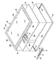
- FIG. 2 is an exploded perspective view of the display device in which the casing of the display device is exploded.
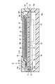
- FIG. 3 is a cross-sectional view of the display device taken along line AA in FIG.
- FIG. 4 is an exploded perspective view showing a housing, a display panel, a humidity control member, and a partition plate in the display device.
- FIG. 5 is an enlarged sectional view showing a part of the display panel.
- FIG. 6 is a perspective view showing a back side of a partition plate in the display device.
- FIG. 7 is a cross-sectional view of the display device taken along line BB in FIG.
- FIG. 8 is a side view schematically showing a humidification processing apparatus according to the embodiment.
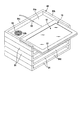
- FIG. 9 is a perspective view showing an example of a shelf of the humidification processing apparatus.
- FIG. 1 is a perspective view showing a display surface side of a display device according to an embodiment
- FIG. 2 is an exploded perspective view of the display device in which a cover of a housing is disassembled.
- an electrophoretic display device 10 using an electrophoretic element or electronic ink is shown.
- the display device 10 includes a substantially rectangular display panel 12 and a rectangular casing (case) 14 that accommodates the display panel.
- the housing 14 has a main body 14a and a cover 14b.
- the main body 14a has a rectangular bottom plate and a plurality of side plates erected along the periphery of the bottom plate, and a step portion is formed at the upper end of each side plate.
- the cover 14b has a rectangular top plate facing the bottom plate of the main body 14a, and a plurality of side plates erected along the periphery of the top plate.
- the cover 14b closes the opening of the main body 14a by fitting with the side plate of the main body 14a.
- the cover 14b has a rectangular display window 16 formed on the top plate.
- the display panel 12 has a rectangular display surface 12a.
- the display panel 12 is disposed in the housing 14 with the display surface 12 a exposed to the display window 16.
- the first injection port 21 is provided on one side plate of the cover 14b, for example, the long side plate.
- the 1st inlet 21 is formed so that the nozzle of the humidifier mentioned later can be inserted.
- FIG. 3 is a cross-sectional view of the display device taken along line AA in FIG. 1, and FIG. 4 is an exploded perspective view showing the display panel, humidity control member, partition plate, and main body.
- the display device 10 includes a rectangular partition plate 50 that functions as a partition member, and a humidity control member 54 for maintaining a constant humidity.
- the partition plate 50 is formed of a metal or a resin film in a rectangular shape that is substantially equal to the inner shape of the main body 14a.
- the partition plate 50 is attached to the opening of the main body 14a with the peripheral edge engaged with the step portion 15 of the main body 14a.
- the partition plate 50 is substantially parallel to the bottom plate of the main body 14a with a gap, and closes the opening.
- the partition plate 50 divides the space in the housing 14 into the first region (first space) AE1 located between the top plate of the cover 14b and the partition plate 50, the bottom plate of the main body 14a, and the partition plate 50. And a second region (second space) AE2 located between the two regions.
- the first region AE1 and the second region AE2 are partitioned almost airtight by the partition plate 50.
- the humidity control member 54 is formed in a rectangular plate shape having a size substantially equal to that of the partition plate 50.
- the humidity control member 54 is disposed in the first area AE1 together with the display panel 12. In one example, the humidity control member 54 is placed on the partition plate 50 and extends over almost the entire area in the first region AE1.
- the humidity adjusting member 54 is formed of a material having high hygroscopicity, for example, a porous material, a polymer high water absorbing material (for example, sodium polyacrylate), or the like.
- the humidity adjusting member 54 absorbs moisture and moisture for a long time and maintains the inside of the first area AE1 at a desired humidity (for example, 30 to 40% or more, 60 to 70% or less).
- the humidity control member 54 is not limited to a plate shape, and various forms such as a frame shape, a plurality of single piece shapes, and a block shape can be selected.
- the display panel 12 is disposed on the humidity control member 54 in the first region AE1. As shown in FIGS. 2 to 4, the display panel 12 includes a rectangular array substrate (TFT substrate, first substrate) 18 and a rectangular counter substrate (second substrate) arranged to face the array substrate 18. Material) 26b and a sheet-like electrophoretic element layer 20 provided between the array substrate 18 and the counter substrate 26b. The peripheral portions of the counter substrate 26b and the electrophoretic element layer 20 are sealed with a frame-shaped sealing member SE made of a moisture-proof material.
- the array substrate 18 is formed in a rectangular shape having a size slightly smaller than that of the partition plate 50.
- the array substrate 18 has a rectangular active area AA capable of displaying an image and a frame area (non-display area) NA located around the active area AA.
- the counter substrate 26 b is formed in a rectangular shape having a size slightly smaller than that of the array substrate 18, and is disposed to face the active area AA and the frame area NA of the array substrate 18.
- the array substrate 18 has an extended end portion 18a that extends outward from one side edge of the counter substrate 26b.
- a drive element (drive IC) 17 is mounted on the extended end portion 18a.
- One end of a flexible printed circuit board (FPC) 19 is joined to one side edge of the extended end portion 18a.
- the FPC 19 is electrically connected to the drive element 17 via a wiring (not shown) of the array substrate 18.
- FIG. 5 is a cross-sectional view of the display panel schematically showing an enlarged part of the display panel 12.
- the scale of the dimension may be changed depending on the component.
- the array substrate 18 includes, for example, an insulating substrate 22 formed of synthetic resin (polyimide or the like) or glass, and an insulating layer 24 formed on the surface of the insulating substrate 22. . Since the insulating substrate 22 is disposed on the side opposite to the display surface 12a, it does not have to be transparent.
- the array substrate 18 has a plurality of pixel electrodes PE provided in a matrix on the insulating layer 24 in the active area AA, switching elements SW (not shown) that supply voltage to the pixel electrodes PE, signal lines, scanning lines, and the like. ing.
- a plurality of wirings are provided on the insulating layer 24 in the frame area NA.
- the pixel electrode PE is an electrode formed of, for example, a transparent conductive material such as indium tin oxide (ITO) or a metal material such as Al, and applies a voltage to the electrophoretic element with a common electrode described later. To do.
- a conductive adhesive layer 25 is provided on the entire surface of the active area AA and the frame area NA of the array substrate 18 so as to overlap the insulating layer 24, the pixel electrode PE, and the wiring.
- the sheet-shaped electrophoretic element layer 20 is disposed so as to overlap the adhesive layer 25, and is adhered to the array substrate 18 by the adhesive layer 25.
- the electrophoretic element layer 20 includes a rectangular first base material (film) 26a, a rectangular second base material (film) 26b disposed opposite to the first base material 26a with a gap, and a first base. It has a large number of microcapsules 30 distributed between the material 26a and the second base material 26b.
- the first base material 26a and the second base material 26b are formed of a transparent resin such as polyethylene terephthalate (PET), for example.
- PET polyethylene terephthalate
- At least the second substrate 26b on the display surface 12a side uses a transparent substrate.
- the second base material 26 b constitutes the counter substrate of the display panel 12.
- a common electrode 28 is provided over the entire inner surface of the second base material 26b.
- the common electrode 28 is an electrode for applying a voltage to the electrophoretic element together with the pixel electrode PE.
- a transparent electrode formed of ITO, magnesium silver, indium zinc oxide (IZO), or the like is used.
- Each microcapsule 30 has a particle size of about 50 to 100 ⁇ m, for example.
- the microcapsule 30 includes a spherical outer shell portion (outer skin) 32, a plurality of white particles (electrophoretic particles) 34a, a plurality of red particles (electrophoretic particles) 34b, and a dispersion medium 36 accommodated in the outer shell 32. ,have.
- one or a plurality of microcapsules 30 are provided in a region facing one pixel electrode PE. Further, the microcapsules 30 are distributed and arranged over the entire area between the first base material 26a and the second base material 26b, that is, over the entire active area AA.
- the outer shell portion (outer skin) 32 of the microcapsule 30 is formed using a polymer resin having translucency such as acrylic resin, urea resin, gum arabic, and the like.
- the dispersion medium 36 is a liquid that disperses the red particles 34 b and the white particles 34 a in the microcapsule 30.
- examples of the dispersion medium 36 include water, alcohol solvents (methanol, ethanol, isopropanol, butanol, octanol, methyl cellosolve, etc.), esters (ethyl acetate, butyl acetate, etc.), and other oils. There may be. These substances can be used alone or as a mixture, and a surfactant or the like may be further blended.
- the white particles 34a are used by being negatively charged, for example.
- the red particles 34b are used, for example, positively charged.
- a charge control agent consisting of particles of electrolyte, surfactant, metal soap, resin, rubber, oil, varnish, compound, etc., titanium coupling agent, aluminum coupling agent, if necessary
- a dispersant such as a silane coupling agent, a lubricant, a stabilizer, and the like can be added.
- pigments such as black, green, blue, yellow, cyan, magenta and the like may be used.
- the electrophoretic element layer 20 is attached to the adhesive layer 25 on the first base material 26 a side, and faces the array substrate 18.
- the electrophoretic element layer 20 covers the active area AA and the frame area NA of the array substrate 18.
- the periphery of the electrophoretic element layer 20 is sealed with the frame-shaped sealing member SE.
- the sealing member SE also functions as a moisture-proof material that prevents moisture and moisture from entering the electrophoretic element layer 20.
- a barrier layer 42 is attached to the outer surface (front surface) of the second base material 26b located on the display surface 12a side via an adhesive layer 40. Further, a protective substrate 44 is laminated on the barrier layer 42.
- the adhesive layer 40, the barrier layer 42, and the protective substrate 44 are formed in a rectangular shape having the same dimensions, and are formed in dimensions slightly larger than the active area AA in plan view.
- the barrier layer 42 is formed of, for example, a transparent inorganic material such as SiN or SiO.
- the barrier layer 42 also functions as a moisture-proof layer that prevents moisture and moisture from entering the electrophoretic element layer 20.
- the protective substrate 44 is made of, for example, a transparent resin material such as PET.
- the outer surface of the protective substrate 44 constitutes the display surface 12 a of the display panel 12.
- the corresponding arbitrary pixel electrode PE is held at a relatively higher potential than the common electrode 28. That is, when the potential of the common electrode 28 is set as a reference potential, the pixel electrode PE is held positive. Thereby, in the microcapsule 30 facing the pixel electrode PE, the positively charged red particles 34b are attracted to the common electrode 28, while the negatively charged white particles 34a are attracted to the pixel electrode PE. As a result, when a pixel corresponding to the pixel electrode PE is observed from the common electrode 28 side, red is visually recognized.
- the display panel 12 is arranged in the first area AE1 of the housing 14 with the array substrate 18 side placed on the humidity control member 54.
- the peripheral edge of the display panel 12 is covered with a cover 14b.
- the barrier layer 42 and the protective substrate 44 of the display panel 12, that is, the display surface 12 a face the entire surface of the display window 16 of the cover 14 b and are exposed to the outside through the display window 16.
- a configuration in which a portion of the surface (upper surface) of the array substrate 18 that is not covered with the sealing member SE, such as an extended end, is covered with a resin or the like can also be employed. In this case, it is possible to employ a configuration in which the members belonging to the first region AE1 in a state of being connected to the array substrate 18 such as the drive element 17 and the FPC 19 are covered with the resin.
- FIG. 6 is a perspective view showing the back side of the partition plate.
- a drive circuit board 60, a battery BT as a power supply unit, and a charging power supply coil 62 are housed in the second region AE ⁇ b> 2 of the housing 14.
- the drive circuit board 60, the battery BT, and the power feeding coil 62 are installed on the back surface of the partition plate 50 (the surface facing the bottom plate of the main body 14a).
- the battery BT and the feeding coil 62 are electrically connected to the drive circuit board 60 via the wiring WL.
- a rectangular first opening 51 a or a notch is formed at one side edge of the partition plate 50.
- a second opening 55 a or a notch is formed at one side edge of the humidity control member 54.
- the first and second openings 51a and 55a are positioned so as to overlap each other, and the first area AE1 and the second area AE2 partially communicate with each other through the first and second openings 51a and 55a.
- the second opening 55a is formed to have a slightly longer dimension than the first opening 51a.
- One end portion (widened portion) 55b of the second opening 55a faces the partition plate 50 without overlapping the first opening 51a.
- the FPC 19 bonded to the array substrate 18 is provided so as to pass from the display panel 12 side through the second opening 55a and the first opening 51a into the second area AE2.
- the other end of the FPC 19 is joined to the drive circuit board 60.
- the drive element 17 of the display panel 12 is electrically connected to the drive circuit board 60 through the FPC 19.
- the first opening 51a and the second opening 55a are fitted with elastic plug members (blocking members) 70 made of rubber or synthetic resin.
- the first and second openings 51a and 55a are closed. That is, by providing the plug member 70, each of the first area AE1 and the second area AE2 becomes an airtight space, and air circulation between these areas is suppressed.
- the FPC 19 extends from the first area AE1 to the second area AE2 through a slit 71 formed in the plug member 70. At the position of the slit 71, the plug member 70 is elastically adhered to both surfaces of the FPC 19 to maintain airtightness.
- the plug member 70 integrally has a cover portion 72 extending toward the display panel 12, and the cover portion 72 covers the joint portion of the FPC 19 and the driving element 17.
- FIG. 7 is a cross-sectional view of the display device taken along line BB in FIG. 1, and is a cross-sectional view showing a cross section including the first inlet of the housing.
- the plug member 70 integrally has a plate-like extension portion 74 that extends laterally from the first opening 51 a.
- the extending portion 74 is disposed on the partition plate 50 in the first region AE1 and further faces the first inlet 21 of the cover 14b.
- a slit-like second injection port 75 is formed in the extending portion 74.
- the second injection port 75 faces the first injection port 21 and communicates with the first region AE1.
- the second opening 55a is widened to a position facing the second injection port 75 rather than the edge of the first opening 51a to form a widened portion 55b.
- the second injection port 75 communicates with the first region AE1 through the widened portion 55b.
- the second inlet 75 is held closed by the elasticity of the plug member 70.
- the cover 14b of the housing 14 may be separately provided in the cover 14b of the housing 14 so that the inside of the first region AE1 is exhausted from the exhaust port 81 when humidified air is injected.
- the exhaust port 81 is provided on the side plate opposite to the first injection port 21 in the cover 14b.
- the space in the housing 14 is partitioned into the first region AE1 and the second region AE2 by the partition plate 50, and is divided into one first region AE1.
- the display panel 12 and the humidity control member 54 are disposed, and the drive circuit board 60, the power supply unit BT, and the like are disposed in the other second region AE2.
- the humidity control member 54 having the humidity control function and the display panel 12 in the first area AE1
- the first area AE1 and the display panel 12 are kept at a constant humidity even while the display device 10 is used in a dry environment. Can keep.
- the drive circuit board 60, the power supply unit BT, etc. which are relatively sensitive to moisture, are arranged in the second area AE2 partitioned from the first area AE1, the humidity adjustment by the humidity adjustment member 54 is hardly affected. Absent.
- the humidity control member 54 is humidified by humidifying the first region AE1 through the first inlet 21. 54 and the display panel 12 can be recovered to an appropriate humidity, and good display quality can be restored.
- the second region AE2 in which the drive circuit board 60, the power supply unit BT, and the like are arranged is partitioned by the partition plate 50 with respect to the first region AE1. Therefore, when the first area AE1 is humidified, the second area AE2 is not humidified, and the drive circuit board 60, the power supply unit BT, and the like are not adversely affected.
- FIG. 8 is a side view schematically showing a part of the humidification processing apparatus according to the embodiment
- FIG. 9 is a perspective view showing an example of a shelf of the humidification processing apparatus.
- the humidifying apparatus includes a box-shaped housing 82, a plurality of mounting shelves (mounting tables) 84 arranged in a plurality of stages in the housing, and the housing 82 or a display device.
- a humidifier 86 that supplies humidified air having a desired humidity to ten first regions AE1, a power supply device 88 that charges the battery BT of the display device 10, and a controller 90 that controls these operations are provided.
- the humidification processing device includes an exhaust pump 92 for exhausting (intake) air from the display device 10.
- the mounting table 84 is opposed to the rear wall 84c, a rectangular bottom wall 84a having dimensions corresponding to the display device 10, left and right side walls 84b and rear walls 84c erected along three sides of the bottom wall 84a. And an insertion port 84d.
- Charging power supply coils 94 are embedded in the corners of the bottom wall 84a.
- the power supply coil 94 is disposed at a position that can face the power supply coil 62 of the display device 10.
- a nozzle 80 is attached to the rear wall 84c. The nozzle 80 penetrates the rear wall 84 c and protrudes a predetermined length inside the mounting table 84.
- the discharge port of the humidifier 86 is connected to the nozzle 80 of each stage through a first pipe 96a branched into a plurality of branches. Further, the discharge port of the humidifier 86 communicates with the space in the housing 82 via the second pipe 96b.
- the power supply device 88 is connected to the power supply coil 94 at each stage via the wiring W2L.
- the exhaust pump 92 communicates with the installation space of each stage through a third pipe 96c branched into a plurality of parts, and can be connected to the exhaust port 81 (see FIG. 9) of the display device 10.
- the display device 10 when the display device 10 is recovered, that is, when humidified and charged, the display device 10 is placed on the bottom wall 84a of the mounting table 84 through the insertion port 84d, and the rear wall. It is pushed to the vicinity of 84c.
- the nozzle 80 is inserted into the first inlet 21 and the second inlet 75 of the display device 10 and communicates with the first region AE1 of the housing 14. Further, the power supply coil 62 of the display device 10 is positioned to face the power supply coil 94 of the mounting table 84.
- humidified air is supplied from the humidifier 86 through the first pipe 96a and the nozzle 80 to the first area AE1 of the display device 10 for a predetermined time.
- the humidity control member 54 is humidified by humidified air to restore the humidity control function of the humidity control member 54, and the humidity in the first region AE1 is recovered to about 30% or more and 70% or less.
- the partition plate 50 and the plug member 70 sufficiently suppress the inflow of the humidified air into the second region AE2.
- the dry air in the first region AE1 may be exhausted by the exhaust pump 92 via the third pipe 96c and the exhaust port 81. By exhausting, it becomes possible to efficiently supply and fill the humidified air from the nozzle 80 into the first region AE1.
- the charging process and the humidity recovery process are not limited to being performed at the same time, but only one of the processes may be performed, or the charging process and the humidity recovery process may be sequentially performed with a time difference.
- humidified air is supplied from the humidifier 86 into the housing 82 via the second pipe 96b, and the display panel 12 of the display device 10 is humidified by the humidified air.
- the electrophoretic element layer 20 can be recovered.
- the humidification processing device can humidify the display device 10 to restore the display quality of the display panel 12, and can charge the battery BT of the display device 10 wirelessly. From the above, according to the present embodiment, a display device and a humidification processing device that can be adjusted or recovered to a desired humidity can be obtained.
- the outer shape of the display panel is not limited to a rectangular shape, but may be other shapes such as a polygonal shape in a plan view, a circular shape, an elliptical shape, and a combination thereof.
- the bending portion is not limited to the side edge portion of the display area, and may be configured to bend the entire display area.
- the material of the constituent member of the display device is not limited to the example described above, and various materials can be selected. What is apparent from the description of the present specification or can be appropriately conceived by those skilled in the art with respect to other operational effects brought about by the above-described embodiment is naturally understood to be brought about by the present invention.
Landscapes
- Physics & Mathematics (AREA)
- General Physics & Mathematics (AREA)
- Nonlinear Science (AREA)
- Engineering & Computer Science (AREA)
- Theoretical Computer Science (AREA)
- Optics & Photonics (AREA)
- Chemical & Material Sciences (AREA)
- Devices For Indicating Variable Information By Combining Individual Elements (AREA)
- Chemical Kinetics & Catalysis (AREA)
- Life Sciences & Earth Sciences (AREA)
- Molecular Biology (AREA)
- Mathematical Physics (AREA)
- Crystallography & Structural Chemistry (AREA)
- Health & Medical Sciences (AREA)
- Electrochemistry (AREA)
- Electrochromic Elements, Electrophoresis, Or Variable Reflection Or Absorption Elements (AREA)
- Liquid Crystal (AREA)
Abstract
実施形態に係る表示装置は、筐体14と、筐体内の空間を第1領域AE1と第2領域AE2とに仕切る仕切り部材50と、第1領域内に配置された表示パネル12であって、複数の画素電極が設けられた第1基板18と、第1基板に対向して設けられた第2基板26bと、第1基板と第2基板との間に設けられた電気泳動素子20と、第1基板および第2基板の周縁部を封止している封止部材SEと、を有する表示パネルと、第1領域内に配置され第1領域内の湿度を保持する調湿部材54と、第2領域内に配置された駆動回路基板60および電源部BTと、を備えている。
Description
本発明の実施形態は、表示装置および表示装置の機能を回復させるための加湿処理装置に関する。
表示装置の一例として、素子基板と対向基板との間に、マイクロカプセルが配列された電気泳動素子を挟持した電気泳動表示装置(電子ペーパーと称する場合もある)が提案されている。この種の電気泳動表示装置は、記憶性を有しているため、表示状態を維持するために電圧を印加する必要がない。
電気泳動表示装置は、乾燥に弱く、日本の冬期間に使い続けると表示領域の周辺部のコントラストが低下する。そこで、電気泳動素子の水分量を検出し、検出値に基づいて電気泳動素子に印加する駆動電圧を制御する表示装置が提案されている。また、表示パネルの密閉空間内に保湿膜を設けた表示装置が提案されている。
電気泳動表示装置は、乾燥に弱く、日本の冬期間に使い続けると表示領域の周辺部のコントラストが低下する。そこで、電気泳動素子の水分量を検出し、検出値に基づいて電気泳動素子に印加する駆動電圧を制御する表示装置が提案されている。また、表示パネルの密閉空間内に保湿膜を設けた表示装置が提案されている。
上述した水分量を検出および制御する電気泳動表示装置では、水分量センサ等を設ける必要があり、製造コストの増加、消費電力の増加等を生じる可能性がある。また、保湿膜を設けた表示装置においては、保湿膜が乾燥した場合、最適な湿度を保持することが困難となる。
ここで述べる実施形態の課題は、所望の湿度に調整あるいは回復可能な表示装置および加湿処理装置を提供することにある。
ここで述べる実施形態の課題は、所望の湿度に調整あるいは回復可能な表示装置および加湿処理装置を提供することにある。
実施形態に係る表示装置は、筐体と、前記筐体内の空間を第1領域と第2領域とに仕切る仕切り部材と、前記第1領域内に配置された表示パネルであって、複数の画素電極が設けられた第1基板と、前記第1基板に対向して設けられた第2基板と、前記第1基板と第2基板との間に設けられた電気泳動素子と、前記第1基板および第2基板の周縁部を封止している封止部材と、を有する表示パネルと、前記第1領域内に配置され前記第1領域内の湿度を保持する調湿部材と、前記第2領域内に配置された駆動回路基板および電源部と、を備えている。
以下、図面を参照しながら、この発明の実施形態について詳細に説明する。
なお、開示はあくまで一例にすぎず、当業者において、発明の主旨を保っての適宜変更であって容易に想到し得るものについては、当然に本発明の範囲に含有されるものである。また、図面は説明をより明確にするため、実際の態様に比べ、各部の幅、厚さ、形状等について模式的に表される場合があるが、あくまで一例であって、本発明の解釈を限定するものではない。また、本明細書および各図において、既出の図に関して前述したものと同様の要素には、同一の符号を付して、詳細な説明を適宜省略あるいは簡略化することがある。
なお、開示はあくまで一例にすぎず、当業者において、発明の主旨を保っての適宜変更であって容易に想到し得るものについては、当然に本発明の範囲に含有されるものである。また、図面は説明をより明確にするため、実際の態様に比べ、各部の幅、厚さ、形状等について模式的に表される場合があるが、あくまで一例であって、本発明の解釈を限定するものではない。また、本明細書および各図において、既出の図に関して前述したものと同様の要素には、同一の符号を付して、詳細な説明を適宜省略あるいは簡略化することがある。
(第1の実施形態)
図1は、実施形態に係る表示装置の表示面側を示す斜視図、図2は、筐体のカバーを分解した表示装置の分解斜視図である。
本実施形態では、電気泳動素子あるいは電子インクを用いた電気泳動表示装置10を示している。図1および図2に示すように、表示装置10は、ほぼ矩形状の表示パネル12と、この表示パネルを収容した矩形状の筐体(ケース)14と、を備えている。筐体14は、本体14aと、カバー14bと、を有している。本体14aは、矩形状の底板と、底板の周縁に沿って立設された複数の側板と、を有し、各側板の上端部に段差部が形成されている。カバー14bは、本体14aの底板に対向する矩形状の天板と、天板の周縁に沿って立設された複数の側板とを有している。カバー14bは、本体14aの側板に嵌合することにより、本体14aの開口部を閉塞している。
カバー14bは、天板に形成された矩形状の表示窓16を有している。表示パネル12は矩形状の表示面12aを有している。表示パネル12は、表示面12aが表示窓16に露出した状態で、筐体14内に配置されている。カバー14bの一側板、例えば、長辺側板に、第1注入口21が設けられている。第1注入口21は、後述する加湿器のノズルを差し込み可能に形成されている。なお、表示窓16の端部と表示パネル12との間に、パッキン等の樹脂部材を介在させる構成を作用することも可能である。
図1は、実施形態に係る表示装置の表示面側を示す斜視図、図2は、筐体のカバーを分解した表示装置の分解斜視図である。
本実施形態では、電気泳動素子あるいは電子インクを用いた電気泳動表示装置10を示している。図1および図2に示すように、表示装置10は、ほぼ矩形状の表示パネル12と、この表示パネルを収容した矩形状の筐体(ケース)14と、を備えている。筐体14は、本体14aと、カバー14bと、を有している。本体14aは、矩形状の底板と、底板の周縁に沿って立設された複数の側板と、を有し、各側板の上端部に段差部が形成されている。カバー14bは、本体14aの底板に対向する矩形状の天板と、天板の周縁に沿って立設された複数の側板とを有している。カバー14bは、本体14aの側板に嵌合することにより、本体14aの開口部を閉塞している。
カバー14bは、天板に形成された矩形状の表示窓16を有している。表示パネル12は矩形状の表示面12aを有している。表示パネル12は、表示面12aが表示窓16に露出した状態で、筐体14内に配置されている。カバー14bの一側板、例えば、長辺側板に、第1注入口21が設けられている。第1注入口21は、後述する加湿器のノズルを差し込み可能に形成されている。なお、表示窓16の端部と表示パネル12との間に、パッキン等の樹脂部材を介在させる構成を作用することも可能である。
図3は、図1の線A-Aに沿った表示装置の断面図、図4は、表示パネル、調湿部材、仕切り板、本体を示す分解斜視図である。
図2ないし図4に示すように、表示装置10は、仕切り部材として機能する矩形状の仕切り板50と、一定の湿度を保つための調湿部材54と、を有している。仕切り板50は、金属あるいは樹脂フィルム等により、本体14aの内形寸法とほぼ等しい矩形状に形成されている。仕切り板50は、その周縁部が本体14aの段差部15に係合した状態で、本体14aの開口部に装着されている。仕切り板50は、本体14aの底板と隙間を置いてほぼ平行に対向しているとともに、開口部を閉塞している。これにより、仕切り板50は、筐体14内の空間を、カバー14bの天板と仕切り板50との間に位置する第1領域(第1空間)AE1と、本体14aの底板と仕切り板50との間に位置する第2領域(第2空間)AE2と、の2つの領域に仕切っている。第1領域AE1と第2領域AE2とは、仕切り板50により、ほぼ気密に区画されている。
図2ないし図4に示すように、表示装置10は、仕切り部材として機能する矩形状の仕切り板50と、一定の湿度を保つための調湿部材54と、を有している。仕切り板50は、金属あるいは樹脂フィルム等により、本体14aの内形寸法とほぼ等しい矩形状に形成されている。仕切り板50は、その周縁部が本体14aの段差部15に係合した状態で、本体14aの開口部に装着されている。仕切り板50は、本体14aの底板と隙間を置いてほぼ平行に対向しているとともに、開口部を閉塞している。これにより、仕切り板50は、筐体14内の空間を、カバー14bの天板と仕切り板50との間に位置する第1領域(第1空間)AE1と、本体14aの底板と仕切り板50との間に位置する第2領域(第2空間)AE2と、の2つの領域に仕切っている。第1領域AE1と第2領域AE2とは、仕切り板50により、ほぼ気密に区画されている。
調湿部材54は、仕切り板50とほぼ等しい大きさの矩形板状に形成されている。調湿部材54は、表示パネル12と共に第1領域AE1内に配置されている。一例では、調湿部材54は、仕切り板50上に載置され、第1領域AE1内のほぼ全域に亘って延在している。調湿部材54は、吸湿性の高い材料、例えば、多孔質材、高分子高吸水材(例えば、ポリアクリル酸ナトリウム)等で形成されている。調湿部材54は、湿気、水分を長時間に亘って吸湿保持し、第1領域AE1内を所望の湿度(例えば、30~40%以上、60~70%以下)に維持する。
なお、調湿部材54は、板状に限定されることなく、枠状、複数の単片形状、ブロック形状等、種々の形態を選択可能である。
なお、調湿部材54は、板状に限定されることなく、枠状、複数の単片形状、ブロック形状等、種々の形態を選択可能である。
表示パネル12は、第1領域AE1内で調湿部材54上に配置されている。図2ないし図4に示すように、表示パネル12は、矩形状のアレイ基板(TFT基板、第1基板)18と、アレイ基板18に対向して配置された矩形状の対向基板(第2基材)26bと、アレイ基板18と対向基板26bとの間に設けられたシート状の電気泳動素子層20と、を備えている。対向基板26bおよび電気泳動素子層20の周縁部は、防湿材からなる枠状の封止部材SEにより封止されている。
アレイ基板18は、仕切り板50よりも僅かに小さい寸法の矩形状に形成されている。アレイ基板18は、画像を表示可能な矩形状のアクティブ領域AAおよびアクティブ領域AAの周囲に位置する額縁領域(非表示領域)NAを有している。対向基板26bは、アレイ基板18よりも僅かに小さな寸法の矩形状に形成され、アレイ基板18のアクティブ領域AAおよび額縁領域NAに対向して配置されている。アレイ基板18は、対向基板26bの一側縁から外側に延出した延出端部18aを有している。延出端部18a上に駆動素子(駆動IC)17が実装されている。延出端部18aの一側縁にフレキシブルプリント配線基板(FPC)19の一端が接合されている。FPC19は、アレイ基板18の図示しない配線を介して駆動素子17に電気的に接続されている。
アレイ基板18は、仕切り板50よりも僅かに小さい寸法の矩形状に形成されている。アレイ基板18は、画像を表示可能な矩形状のアクティブ領域AAおよびアクティブ領域AAの周囲に位置する額縁領域(非表示領域)NAを有している。対向基板26bは、アレイ基板18よりも僅かに小さな寸法の矩形状に形成され、アレイ基板18のアクティブ領域AAおよび額縁領域NAに対向して配置されている。アレイ基板18は、対向基板26bの一側縁から外側に延出した延出端部18aを有している。延出端部18a上に駆動素子(駆動IC)17が実装されている。延出端部18aの一側縁にフレキシブルプリント配線基板(FPC)19の一端が接合されている。FPC19は、アレイ基板18の図示しない配線を介して駆動素子17に電気的に接続されている。
図5は、表示パネル12の一部を拡大して模式的に示す表示パネルの断面図である。図5においては、各構成要素を見やすくするため、構成要素によって寸法の縮尺を変更して示すことがある。
図5に示すように、アレイ基板18は、例えば、合成樹脂(ポリイミド等)あるいはガラスで形成された絶縁基板22と、絶縁基板22の表面に形成された絶縁層24と、を有している。絶縁基板22は、表示面12aと反対側に配置されるため、透明でなくてもよい。アレイ基板18は、アクティブ領域AAにおいて、絶縁層24上にマトリクス状に設けられた複数の画素電極PE、画素電極PEに電圧を供給する図示しないスイッチング素子SW、信号線、走査線等を有している。額縁領域NAにおいて、絶縁層24上に図示しない複数の配線が設けられている。画素電極PEは、例えば、インジウム・ティン・オキサイド(ITO)等の透明導電材料やAl等の金属材料等により形成された電極であり、後述する共通電極との間で電気泳動素子に電圧を印加する。絶縁層24、画素電極PE、配線に重ねて、アレイ基板18のアクティブ領域AAおよび額縁領域NAの全面に導電性の粘着層25が設けられている。
図5に示すように、アレイ基板18は、例えば、合成樹脂(ポリイミド等)あるいはガラスで形成された絶縁基板22と、絶縁基板22の表面に形成された絶縁層24と、を有している。絶縁基板22は、表示面12aと反対側に配置されるため、透明でなくてもよい。アレイ基板18は、アクティブ領域AAにおいて、絶縁層24上にマトリクス状に設けられた複数の画素電極PE、画素電極PEに電圧を供給する図示しないスイッチング素子SW、信号線、走査線等を有している。額縁領域NAにおいて、絶縁層24上に図示しない複数の配線が設けられている。画素電極PEは、例えば、インジウム・ティン・オキサイド(ITO)等の透明導電材料やAl等の金属材料等により形成された電極であり、後述する共通電極との間で電気泳動素子に電圧を印加する。絶縁層24、画素電極PE、配線に重ねて、アレイ基板18のアクティブ領域AAおよび額縁領域NAの全面に導電性の粘着層25が設けられている。
シート状の電気泳動素子層20は、粘着層25に重ねて配置され、この粘着層25によりアレイ基板18に貼付されている。電気泳動素子層20は、矩形状の第1基材(フィルム)26aと、第1基材26aに隙間を置いて対向配置された矩形状の第2基材(フィルム)26bと、第1基材26aと第2基材26bとの間に分散配置された多数のマイクロカプセル30と、を有している。第1基材26aおよび第2基材26bは、例えば、ポリエチレンテレフタレート(PET)等の透明樹脂で形成されている。少なくとも、表示面12a側となる第2基材26bは、透明な基材を用いる。本実施形態では、第2基材26bは、表示パネル12の対向基板を構成している。第2基材26bの内面の全面に亘り共通電極28が設けられている。共通電極28は、画素電極PEとともに電気泳動素子に電圧を印加する電極であり、例えば、ITO、マグネシウム銀、インジウム亜鉛酸化物(IZO)等から形成された透明電極を用いている。
各マイクロカプセル30は、例えば、50~100μm程度の粒径を有している。マイクロカプセル30は、球状の外殻部(外皮)32と、外皮32内に収容された複数の白色粒子(電気泳動粒子)34a、複数の赤色粒子(電気泳動粒子)34b、および分散媒36と、を有している。図示では、模式的に少数に示しているが、マイクロカプセル30は、1つの画素電極PEと対向する領域に1つあるいは複数個、設けられている。更に、マイクロカプセル30は、第1基材26aと第2基材26bとの間の全域に亘って、すなわち、アクティブ領域AAの全域に亘って、分散配置されている。
マイクロカプセル30の外殻部(外皮)32は、例えば、アクリル樹脂、ユリア樹脂、アラビアガムなどの透光性を持つ高分子樹脂などを用いて形成されている。分散媒36は、マイクロカプセル30内において、赤色粒子34bと、白色粒子34aとを分散させる液体である。分散媒36としては、水、アルコール系溶媒(メタノール、エタノール、イソプロパノール、ブタノール、オクタノール、メチルセロソルブなど)、エステル類(酢酸エチル、酢酸ブチルなど)などを例示することができ、その他の油類であってもよい。これらの物質は単独または混合物として用いることができ、さらに界面活性剤などを配合してもよい。
白色粒子34aは、例えば、負に帯電されて用いられる。赤色粒子34bは、例えば、正に帯電されて用いられる。
これらの各粒子には、必要に応じて、電解質、界面活性剤、金属石鹸、樹脂、ゴム、油、ワニス、コンパウンドなどの粒子からなる荷電制御剤、チタン系カップリング剤、アルミニウム系カップリング剤、シラン系カップリング剤等の分散剤、潤滑剤、安定化剤などを添加することができる。
また、白色粒子34aおよび赤色粒子34bに代えて、例えば黒色、緑色、青色、イエロー、シアン、マゼンタなどの顔料を用いてもよい。
これらの各粒子には、必要に応じて、電解質、界面活性剤、金属石鹸、樹脂、ゴム、油、ワニス、コンパウンドなどの粒子からなる荷電制御剤、チタン系カップリング剤、アルミニウム系カップリング剤、シラン系カップリング剤等の分散剤、潤滑剤、安定化剤などを添加することができる。
また、白色粒子34aおよび赤色粒子34bに代えて、例えば黒色、緑色、青色、イエロー、シアン、マゼンタなどの顔料を用いてもよい。
電気泳動素子層20は、第1基材26a側が粘着層25に貼付され、アレイ基板18に対向している。電気泳動素子層20は、アレイ基板18のアクティブ領域AAおよび額縁領域NAを覆っている。前述したように、電気泳動素子層20の周囲は、枠状の封止部材SEにより封止されている。封止部材SEは、電気泳動素子層20内への水分、湿気の浸入を防止する防湿材としても機能する。
表示面12a側に位置する第2基材26bの外面(表面)に接着層40を介してバリア層42が貼付されている。更に、バリア層42上に保護基材44が積層されている。接着層40、バリア層42、保護基材44は、同一寸法の矩形状に形成され、また、平面視で、アクティブ領域AAよりも僅かに大きい寸法に形成されている。
バリア層42は、例えば、SiN、SiO等の透明な無機材料で形成されている。バリア層42は、電気泳動素子層20への水分、湿気の浸入を防止する防湿層としても機能する。保護基材44は、例えば、PET等の透明な樹脂材料で形成されている。保護基材44の外面は、表示パネル12の表示面12aを構成している。
バリア層42は、例えば、SiN、SiO等の透明な無機材料で形成されている。バリア層42は、電気泳動素子層20への水分、湿気の浸入を防止する防湿層としても機能する。保護基材44は、例えば、PET等の透明な樹脂材料で形成されている。保護基材44の外面は、表示パネル12の表示面12aを構成している。
表示パネル12において、電気泳動素子層20に赤表示する場合、対応する任意の画素電極PEを共通電極28よりも相対的に高電位に保持する。すなわち、共通電極28の電位を基準電位としたとき、画素電極PEが正極性に保持される。これにより、画素電極PEに対向するマイクロカプセル30において、正に帯電した赤色粒子34bが共通電極28に引き寄せられる一方、負に帯電した白色粒子34aが画素電極PEに引き寄せられる。その結果、共通電極28側から画素電極PEに対応する画素を観察すると赤色が視認される。一方、任意の画素に白表示させる場合には、共通電極28の電位を基準電位としたとき、対応する画素電極PEが負極性に保持される。これにより、マイクロカプセル30において、負に帯電した白色粒子34aが共通電極28側へ引き寄せられる一方、正に帯電した赤色粒子34bが画素電極PEに引き寄せられる。その結果、この画素を観察すると白色が視認される。このように、アレイ基板18のアクティブ領域AAでは、任意の画素電極PEに電圧を印加することにより、任意の文字、画像等を表示あるいは書換えすることができる。
図3に示すように、表示パネル12は、アレイ基板18側が調湿部材54上に載置された状態で筐体14の第1領域AE1内に配置されている。表示パネル12の周縁部はカバー14bにより覆われている。表示パネル12のバリア層42および保護基材44、すなわち、表示面12aは、カバー14bの表示窓16の全面に対向し、表示窓16を通して外部に露出している。なお、アレイ基板18の表面(上面)の内、延出端部等の封止部材SEに覆われていない部分を樹脂等で覆う構成も採用可能である。この場合、駆動素子17やFPC19等、アレイ基板18に接続された状態で第1領域AE1に属する部材についても係る樹脂で覆う構成を採用することができる。
図6は、仕切り板の背面側を示す斜視図である。図3および図6に示すように、筐体14の第2領域AE2内に、駆動回路基板60、電源部としてのバッテリBT、および充電用の給電コイル62が収納されている。一例では、駆動回路基板60、バッテリBT、および給電コイル62は、仕切り板50の背面(本体14aの底板と対向する面)上に設置されている。バッテリBTおよび給電コイル62は、配線WLを介して駆動回路基板60に電気的に接続されている。
図3、図4、図6に示すように、仕切り板50の一側縁部に矩形状の第1開口51aあるいは切欠部が形成されている。また、調湿部材54の一側縁部に第2開口55aあるいは切欠部が形成されている。第1および第2開口51a、55aは互いに重なって位置し、第1および第2開口51a、55aを通して、第1領域AE1と第2領域AE2とが部分的に連通している。第2開口55aは、第1開口51aよりも僅かに長い寸法に形成されている。第2開口55aの一端部(拡幅部)55bは、第1開口51aに重なることなく、仕切り板50に対向している。
アレイ基板18に接合されたFPC19は、表示パネル12側から第2開口55aおよび第1開口51aを通過して第2領域AE2内に回り込んで設けられている。FPC19の他端は、駆動回路基板60に接合されている。これにより、表示パネル12の駆動素子17は、FPC19を介して、駆動回路基板60に電気的に接続されている。
アレイ基板18に接合されたFPC19は、表示パネル12側から第2開口55aおよび第1開口51aを通過して第2領域AE2内に回り込んで設けられている。FPC19の他端は、駆動回路基板60に接合されている。これにより、表示パネル12の駆動素子17は、FPC19を介して、駆動回路基板60に電気的に接続されている。
図2ないし図4に示すように、第1開口51aおよび第2開口55aに、ゴムあるいは合成樹脂等で形成された弾性を有する栓部材(閉塞部材)70が装着され、この栓部材70により第1および第2開口51a、55aが閉塞されている。すなわち、栓部材70を設けることにより、第1領域AE1と第2領域AE2とは各々で気密空間となり、これらの領域間の空気の流通は抑制される。FPC19は、栓部材70に形成されたスリット71を通して、第1領域AE1から第2領域AE2に延出している。スリット71の位置で、栓部材70はFPC19の両面に弾性的に密着し、気密性を維持している。栓部材70は、表示パネル12側に延出したカバー部72を一体に有し、このカバー部72は、FPC19の接合部および駆動素子17を覆っている。
図7は、図1の線B-Bに沿った表示装置の断面図であり、筐体の第1注入口を含む断面を示す断面図である。図2、図4、図7に示すように、栓部材70は、第1開口51aから側方に延在する板状の延出部74を一体に有している。延出部74は、第1領域AE1において、仕切り板50上に配置され、更に、カバー14bの第1注入口21に対向している。延出部74に、スリット状の第2注入口75が形成されている。第2注入口75は、第1注入口21に対向しているとともに、第1領域AE1に連通している。本実施形態では、第2開口55aは、第1開口51aの縁部よりも第2注入口75に対向する位置まで拡幅され拡幅部55bを形成している。第2注入口75は、この拡幅部55bを介して第1領域AE1に連通している。なお、通常、第2注入口75は、栓部材70の弾性により、閉じた状態に保持されている。
図7に2点鎖線で示すように、後述する加湿器のノズル80を筐体14の第1注入口21に差し込むと、ノズル80の先端は栓部材70の第2注入口75に挿通され、筐体14の第1領域AE1内に突出する。この状態で、加湿器から加湿空気を供給し、ノズルから第1領域AE内に加湿空気を送りこむことができる。ノズル80を引き抜くと、栓部材70の弾性により、第2注入口75が閉じ、第1領域AE1の気密性が維持される。
なお、筐体14のカバー14bに別途、排気口81(図9参照)を設け、加湿空気を注入する際、排気口81から第1領域AE1内を排気するようにしてもよい。この場合、排気口81は、カバー14bにおいて、第1注入口21と反対側の側板に設けることが望ましい。注入しながら第1領域AE1の乾燥空気を排気することにより、第1領域AE1に効率良く加湿空気を充填することができる。
なお、筐体14のカバー14bに別途、排気口81(図9参照)を設け、加湿空気を注入する際、排気口81から第1領域AE1内を排気するようにしてもよい。この場合、排気口81は、カバー14bにおいて、第1注入口21と反対側の側板に設けることが望ましい。注入しながら第1領域AE1の乾燥空気を排気することにより、第1領域AE1に効率良く加湿空気を充填することができる。
以上のように構成された本実施形態に係る表示装置10によれば、仕切り板50により筐体14内の空間を第1領域AE1と第2領域AE2とに仕切り、一方の第1領域AE1に表示パネル12および調湿部材54を配置し、他方の第2領域AE2内に駆動回路基板60、電源部BT等を配置している。調湿機能を持つ調湿部材54および表示パネル12を第1領域AE1に設けることにより、表示装置10を乾燥した環境で使用している間も、第1領域AE1および表示パネル12を一定の湿度を保つことができる。これにより、電気泳動素子層20の劣化を抑制し、長期間に亘って良好な表示品位を維持可能な表示装置が得られる。比較的に湿気に弱い駆動回路基板60、電源部BT等は、第1領域AE1に対して仕切られた第2領域AE2に配置されているため、調湿部材54による調湿による影響はほとんど受けない。
更に、本実施形態に係る表示装置によれば、調湿部材54が乾燥して表示品位が低下した場合でも、第1注入口21を介して第1領域AE1を加湿することにより、調湿部材54および表示パネル12を適度な湿度に回復し、良好な表示品位を復活することが可能である。前述したように、駆動回路基板60、電源部BT等が配置された第2領域AE2は、第1領域AE1に対して仕切り板50で仕切られている。そのため、第1領域AE1を加湿する際、第2領域AE2が加湿されることがなく、駆動回路基板60、電源部BT等が悪影響を受けることがない。
次に、表示装置10を回復処理するための加湿処理装置の一例を説明する。
図8は、実施形態に係る加湿処理装置の一部を破断して概略的に示す側面図、図9は、加湿処理装置の棚の一例を示す斜視図である。これらの図に示すように、加湿処理装置は、箱状のハウジング82と、ハウジング内に複数段重ねて配置された複数の載置棚(載置台)84と、ハウジング82内、あるいは、表示装置10の第1領域AE1に所望湿度の加湿空気を供給する加湿器86と、表示装置10のバッテリBTを充電する電力供給装置88と、これらの動作を制御するコントローラ90と、を備えている。本実施形態では、加湿処理装置は、表示装置10内から空気を排気(吸気)するための排気ポンプ92を備えている。
図8は、実施形態に係る加湿処理装置の一部を破断して概略的に示す側面図、図9は、加湿処理装置の棚の一例を示す斜視図である。これらの図に示すように、加湿処理装置は、箱状のハウジング82と、ハウジング内に複数段重ねて配置された複数の載置棚(載置台)84と、ハウジング82内、あるいは、表示装置10の第1領域AE1に所望湿度の加湿空気を供給する加湿器86と、表示装置10のバッテリBTを充電する電力供給装置88と、これらの動作を制御するコントローラ90と、を備えている。本実施形態では、加湿処理装置は、表示装置10内から空気を排気(吸気)するための排気ポンプ92を備えている。
載置台84は、表示装置10に対応した寸法を有する矩形状の底壁84aと、底壁84aの3辺に沿って立設された左右の側壁84bおよび後壁84cと、後壁84cに対向する挿入口84dと、を有している。底壁84aの角部に充電用の給電コイル94が埋め込まれている。給電コイル94は、表示装置10の給電コイル62と対向可能な位置に配置されている。後壁84cにノズル80が取り付けられている。ノズル80は、後壁84cを貫通し、載置台84の内側に所定長さ突出している。
加湿器86の吐出口は、複数に分岐した第1配管96aを介して各段のノズル80に接続されている。また、加湿器86の吐出口は、第2配管96bを介して、ハウジング82内の空間に連通している。電力供給装置88は、配線W2Lを介して、各段の給電コイル94に接続されている。更に、排気ポンプ92は、複数に分岐した第3配管96cを介して、各段の設置空間に連通し、表示装置10の排気口81(図9参照)に接続可能としている。
図8および図9に示すように、表示装置10の回復処理、すなわち、加湿および充電する場合、表示装置10は、挿入口84dを通して、載置台84の底壁84a上に載置され、後壁84cの近傍まで押し込まれる。ノズル80は、表示装置10の第1注入口21および第2注入口75に差し込まれ、筐体14の第1領域AE1に連通する。また、表示装置10の給電コイル62は、載置台84の給電コイル94と対向して位置する。
この状態で、電力供給装置88から配線W2Lを介して給電コイル94に通電すると、給電コイル94が励起し、表示装置10の給電コイル62に磁力を印加する。これにより、給電コイル62が電力を発生し、バッテリBTに充電する。このようにしてバッテリBTを所定時間、充電処理する。
この状態で、電力供給装置88から配線W2Lを介して給電コイル94に通電すると、給電コイル94が励起し、表示装置10の給電コイル62に磁力を印加する。これにより、給電コイル62が電力を発生し、バッテリBTに充電する。このようにしてバッテリBTを所定時間、充電処理する。
充電処理の間、加湿器86から第1配管96aおよびノズル80を通して、表示装置10の第1領域AE1に加湿空気を所定時間、供給する。加湿空気により調湿部材54を加湿して調湿部材54の調湿機能を回復させるとともに、第1領域AE1内の湿度を30%以上、70%以下程度に回復させる。加湿処理の間、仕切り板50および栓部材70により、係る加湿空気の第2領域AE2への流入は十分に抑制される。
加湿処理の間、排気ポンプ92により第3配管96c、排気口81を介して第1領域AE1内の乾燥空気を排気してもよい。排気することにより、加湿空気をノズル80から第1領域AE1内に効率良く供給、充填することが可能となる。
加湿処理の間、排気ポンプ92により第3配管96c、排気口81を介して第1領域AE1内の乾燥空気を排気してもよい。排気することにより、加湿空気をノズル80から第1領域AE1内に効率良く供給、充填することが可能となる。
なお、充電処理および湿度回復処理を同時に行う場合に限らず、いずれか一方の処理のみを実施してもよいし、充電処理と湿度回復処理とを時差を持って順番に実施するようにしてもよい。第1注入口を持たない表示装置の湿度回復処理を行う場合、加湿器86から第2配管96bを介してハウジング82内に加湿空気を供給し、加湿空気により表示装置10の表示パネル12を加湿し、電気泳動素子層20を回復させることも可能である。
以上のように、加湿処理装置は、表示装置10を加湿し、表示パネル12の表示品位を回復することができるとともに、表示装置10のバッテリBTをワイヤレスで充電することができる。以上のことから、本実施形態によれば、所望の湿度に調整あるいは回復可能な表示装置および加湿処理装置が得られる。
以上のように、加湿処理装置は、表示装置10を加湿し、表示パネル12の表示品位を回復することができるとともに、表示装置10のバッテリBTをワイヤレスで充電することができる。以上のことから、本実施形態によれば、所望の湿度に調整あるいは回復可能な表示装置および加湿処理装置が得られる。
本発明の実施形態を説明したが、実施形態は、例として提示したものであり、発明の範囲を限定することは意図していない。新規な実施形態は、その他の様々な形態で実施されることが可能であり、発明の要旨を逸脱しない範囲で、種々の省略、置き換え、変更を行うことができる。実施形態やその変形例は、発明の範囲や要旨に含まれるとともに、特許請求の範囲に記載された発明とその均等の範囲に含まれる。
本発明の実施形態として上述した各構成を基にして、当業者が適宜設計変更して実施し得る全ての構成も、本発明の要旨を包含する限り、本発明の範囲に属する。例えば、表示パネル外形状は、矩形状に限定されることなく、平面視多角形状や円形、楕円形、およびこれらを組み合わせた形状等の他の形状としてもよい。湾曲部は、表示領域の側縁部に限らず、表示領域全体を湾曲させる構成としてもよい。表示装置の構成部材の材料は、上述した例に限らず、種々選択可能である。
上述した実施形態によりもたらされる他の作用効果について本明細書の記載から明らかなもの、又は当業者において適宜想到し得るものついては、当然に本発明によりもたらされるものと解される。
上述した実施形態によりもたらされる他の作用効果について本明細書の記載から明らかなもの、又は当業者において適宜想到し得るものついては、当然に本発明によりもたらされるものと解される。
Claims (9)
- 筐体と、
前記筐体内の空間を第1領域と第2領域とに仕切る仕切り部材と、
前記第1領域内に配置された表示パネルであって、複数の画素電極が設けられた第1基板と、前記第1基板に対向して設けられた第2基板と、前記第1基板と第2基板との間に設けられた電気泳動素子と、前記第1基板および第2基板の周縁部を封止している封止部材と、を有する表示パネルと、
前記第1領域内に配置され前記第1領域内の湿度を保持する調湿部材と、
前記第2領域内に配置された駆動回路基板および電源部と、
を備える表示装置。 - 前記仕切り部材は、前記第1領域と第2領域とを連通する第1開口を有し、
前記表示パネルの第1基板は、前記第1開口を通る配線部材により、前記駆動回路基板に電気的に接続され、前記第1開口を閉じる閉塞部材を更に備えている請求項1に記載の表示装置。 - 前記仕切り部材は、仕切り板で構成され、前記表示パネルは、前記仕切り板に対向して配置され、前記調湿部材は板状に形成され、前記表示パネルと仕切り板との間に配置されている請求項1又は2に記載の表示装置。
- 前記筐体は、前記第1領域に連通可能な第1注入口を有し、前記閉塞部材は、前記第1注入口に対向しているとともに前記第1領域に連通可能な第2注入口を有している請求項2に記載の表示装置。
- 前記閉塞部材は弾性部材で形成され、前記第2注入口は弾性的に開放可能に閉じられている請求項4に記載の表示装置。
- 前記調湿部材は、多孔質材あるいは高吸水性高分子材料で形成されている請求項1に記載の表示装置。
- 電気泳動素子を用いる表示パネルと、前記表示パネルを収容する筐体と、を備えた表示装置を載置する載置台と、
前記表示装置に充電する電力供給装置と、
前記表示装置を加湿する加湿器と、
を備える加湿処理装置。 - 前記加湿器は、前記表示装置の筐体に設けられた注入口を介して前記筐体内に加湿空気を供給するノズルを備えている請求項7に記載の加湿処理装置。
- 前記筐体内の空気を排気する排気装置を更に備えている請求項8に記載の加湿処理装置。
Applications Claiming Priority (2)
| Application Number | Priority Date | Filing Date | Title |
|---|---|---|---|
| JP2018104993A JP7043349B2 (ja) | 2018-05-31 | 2018-05-31 | 表示装置および加湿処理装置 |
| JP2018-104993 | 2018-05-31 |
Publications (1)
| Publication Number | Publication Date |
|---|---|
| WO2019230380A1 true WO2019230380A1 (ja) | 2019-12-05 |
Family
ID=68697618
Family Applications (1)
| Application Number | Title | Priority Date | Filing Date |
|---|---|---|---|
| PCT/JP2019/019184 Ceased WO2019230380A1 (ja) | 2018-05-31 | 2019-05-14 | 表示装置および加湿処理装置 |
Country Status (2)
| Country | Link |
|---|---|
| JP (1) | JP7043349B2 (ja) |
| WO (1) | WO2019230380A1 (ja) |
Cited By (1)
| Publication number | Priority date | Publication date | Assignee | Title |
|---|---|---|---|---|
| CN116047804A (zh) * | 2023-03-29 | 2023-05-02 | 惠科股份有限公司 | 一种面板防水结构及显示器 |
Families Citing this family (1)
| Publication number | Priority date | Publication date | Assignee | Title |
|---|---|---|---|---|
| JP2021173947A (ja) * | 2020-04-29 | 2021-11-01 | 株式会社デンソー | 表示装置およびその製造方法 |
Citations (8)
| Publication number | Priority date | Publication date | Assignee | Title |
|---|---|---|---|---|
| JPS62254130A (ja) * | 1986-04-28 | 1987-11-05 | Nippon Mektron Ltd | 電気泳動表示装置 |
| JP2003015169A (ja) * | 2001-06-27 | 2003-01-15 | Fuji Xerox Co Ltd | 画像表示媒体 |
| JP2009080396A (ja) * | 2007-09-27 | 2009-04-16 | Victor Co Of Japan Ltd | 液晶表示素子 |
| JP2011180361A (ja) * | 2010-03-01 | 2011-09-15 | Seiko Epson Corp | 表示装置 |
| JP2012215745A (ja) * | 2011-04-01 | 2012-11-08 | Seiko Epson Corp | 電気泳動表示装置の製造方法および電気泳動表示装置 |
| JP2013127552A (ja) * | 2011-12-19 | 2013-06-27 | Konica Minolta Business Technologies Inc | データ記憶方法、薄型表示装置の保持装置、および薄型表示装置 |
| CN106990637A (zh) * | 2017-04-05 | 2017-07-28 | 国网黑龙江省电力有限公司信息通信公司 | 电子墨水显示器 |
| JP2018045033A (ja) * | 2016-09-13 | 2018-03-22 | セイコーエプソン株式会社 | 電気泳動表示装置、電気泳動表示装置の製造方法および電子機器 |
-
2018
- 2018-05-31 JP JP2018104993A patent/JP7043349B2/ja active Active
-
2019
- 2019-05-14 WO PCT/JP2019/019184 patent/WO2019230380A1/ja not_active Ceased
Patent Citations (8)
| Publication number | Priority date | Publication date | Assignee | Title |
|---|---|---|---|---|
| JPS62254130A (ja) * | 1986-04-28 | 1987-11-05 | Nippon Mektron Ltd | 電気泳動表示装置 |
| JP2003015169A (ja) * | 2001-06-27 | 2003-01-15 | Fuji Xerox Co Ltd | 画像表示媒体 |
| JP2009080396A (ja) * | 2007-09-27 | 2009-04-16 | Victor Co Of Japan Ltd | 液晶表示素子 |
| JP2011180361A (ja) * | 2010-03-01 | 2011-09-15 | Seiko Epson Corp | 表示装置 |
| JP2012215745A (ja) * | 2011-04-01 | 2012-11-08 | Seiko Epson Corp | 電気泳動表示装置の製造方法および電気泳動表示装置 |
| JP2013127552A (ja) * | 2011-12-19 | 2013-06-27 | Konica Minolta Business Technologies Inc | データ記憶方法、薄型表示装置の保持装置、および薄型表示装置 |
| JP2018045033A (ja) * | 2016-09-13 | 2018-03-22 | セイコーエプソン株式会社 | 電気泳動表示装置、電気泳動表示装置の製造方法および電子機器 |
| CN106990637A (zh) * | 2017-04-05 | 2017-07-28 | 国网黑龙江省电力有限公司信息通信公司 | 电子墨水显示器 |
Cited By (2)
| Publication number | Priority date | Publication date | Assignee | Title |
|---|---|---|---|---|
| CN116047804A (zh) * | 2023-03-29 | 2023-05-02 | 惠科股份有限公司 | 一种面板防水结构及显示器 |
| US12566344B2 (en) | 2023-03-29 | 2026-03-03 | HKC Corporation Limited | Panel waterproof structure and display |
Also Published As
| Publication number | Publication date |
|---|---|
| JP2019211517A (ja) | 2019-12-12 |
| JP7043349B2 (ja) | 2022-03-29 |
Similar Documents
| Publication | Publication Date | Title |
|---|---|---|
| US10924704B2 (en) | Display apparatus | |
| TWI677734B (zh) | 可撓性顯示裝置 | |
| JP5594069B2 (ja) | 電気泳動表示装置及び電子機器 | |
| US10268086B2 (en) | Electronic device | |
| CN102375281B (zh) | 显示器 | |
| US20100033451A1 (en) | Flexible Display Panel and Fabricating Method thereof | |
| US10816837B2 (en) | Display device | |
| US10051766B2 (en) | Electromagnetic wave shielding structure and display device including the same | |
| US9323126B2 (en) | Electrophoretic particles, method for manufacturing electrophoretic particles, electrophoresis dispersion, display device, and electronic apparatus | |
| US7663800B2 (en) | Electrophoresis display device and electronic apparatus | |
| CN102914897B (zh) | 显示面板及显示装置 | |
| WO2019230380A1 (ja) | 表示装置および加湿処理装置 | |
| US20080239460A1 (en) | Method of driving organic transistor and electrophoretic display device | |
| CN103035207A (zh) | 电子纸显示器 | |
| CN111402757B (zh) | 显示模组、电子设备和显示模组的制造方法 | |
| US20100265565A1 (en) | Display Device with Improved Display Performance | |
| TWI533069B (zh) | 電泳顯示裝置及電子機器 | |
| JP2019060983A (ja) | 表示装置および表示装置を備えた表示システム | |
| CN112492153B (zh) | 摄像头模组及电子设备 | |
| US10191513B2 (en) | Waterproof display apparatus and method of assembling the same | |
| JP4874558B2 (ja) | 表示装置用収納容器及びこれを有する液晶表示装置 | |
| JP2009031640A (ja) | 電気泳動表示パネルの製造方法及び電気泳動表示パネル | |
| JP2006146121A5 (ja) | ||
| JP2011145537A (ja) | 電気光学装置及び電子機器 | |
| US8466884B2 (en) | Touch electrophoretic display apparatus |
Legal Events
| Date | Code | Title | Description |
|---|---|---|---|
| 121 | Ep: the epo has been informed by wipo that ep was designated in this application |
Ref document number: 19811224 Country of ref document: EP Kind code of ref document: A1 |
|
| NENP | Non-entry into the national phase |
Ref country code: DE |
|
| 122 | Ep: pct application non-entry in european phase |
Ref document number: 19811224 Country of ref document: EP Kind code of ref document: A1 |