WO2019225083A1 - 洗濯機 - Google Patents
洗濯機 Download PDFInfo
- Publication number
- WO2019225083A1 WO2019225083A1 PCT/JP2019/006363 JP2019006363W WO2019225083A1 WO 2019225083 A1 WO2019225083 A1 WO 2019225083A1 JP 2019006363 W JP2019006363 W JP 2019006363W WO 2019225083 A1 WO2019225083 A1 WO 2019225083A1
- Authority
- WO
- WIPO (PCT)
- Prior art keywords
- rib
- washing machine
- accommodating
- housing
- hole
- Prior art date
- Legal status (The legal status is an assumption and is not a legal conclusion. Google has not performed a legal analysis and makes no representation as to the accuracy of the status listed.)
- Ceased
Links
Images





Classifications
-
- D—TEXTILES; PAPER
- D06—TREATMENT OF TEXTILES OR THE LIKE; LAUNDERING; FLEXIBLE MATERIALS NOT OTHERWISE PROVIDED FOR
- D06F—LAUNDERING, DRYING, IRONING, PRESSING OR FOLDING TEXTILE ARTICLES
- D06F39/00—Details of washing machines not specific to a single type of machines covered by groups D06F9/00 - D06F27/00
- D06F39/12—Casings; Tubs
Definitions
- the present invention relates to a washing machine.
- the washing machine described in Patent Document 1 includes a partial washing device including an ultrasonic vibrator, an ultrasonic vibration horn, a water supply pipe, and a fixing member.
- the ultrasonic vibration horn amplifies the ultrasonic vibration of the ultrasonic vibrator.
- the water supply pipe supplies water to the tip of the ultrasonic vibration horn.
- the partial washing device is accommodated in the fixed member by inserting the partial washing device into the fixed member.
- the washing machine described in Patent Document 1 has room for improvement in terms of user convenience.
- the cover of the partial washing device is locked to the fixing member.
- the lower end opening of the fixing member is closed.
- the water droplets flow into the fixed member, the water droplets accumulate inside the fixed member.
- This invention provides the washing machine which can suppress that a water droplet accumulates inside a storage part in the state in which the external apparatus was stored in the storage part provided in the washing machine.
- the washing machine wash the laundry.
- the washing machine includes a storage unit.
- An external device can be accommodated in the accommodating portion.
- the accommodating portion has a communication hole portion.
- the communication hole is formed at the bottom of the housing.
- the communication hole portion communicates the inside of the housing portion with the outside of the housing portion in a state where the external device is housed in the housing portion.
- the present invention it is possible to prevent water droplets from being accumulated inside the housing portion in a state where the external device is housed in the housing portion provided in the washing machine.
- FIG. 1 is a perspective view of a washing machine according to a first embodiment of the present invention. It is a perspective view which shows the washing machine of a door open state. It is a perspective view of the washing machine in which the external apparatus was accommodated in the accommodating part. It is a block diagram which shows the structure of a washing machine. It is a 1st perspective view of an accommodating part. It is an enlarged view of an accommodating part. It is an end view of the housing
- (B) It is a figure which shows the external apparatus accommodated in the accommodating part. It is a 2nd perspective view of an accommodating part. It is a 3rd perspective view of an accommodating part. It is a 1st sectional view of a storage part, a case, and a base. It is an enlarged view of sectional drawing of an accommodating part. It is a 2nd sectional view of a storage part, a case, and a base. It is a 3rd sectional view of a storage part, a case, and a base.
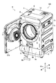
- FIG. 1 is a perspective view of the washing machine 100 with the door 2 closed.
- FIG. 2 is a perspective view of the washing machine 100 with the door 2 opened.
- the washing machine 100 includes a housing 1, a door 2, an input unit 3, a water supply hose connection unit 4, a drainage hose connection unit 5, a hinge mechanism 6, and a bottom base. 7.
- the front / rear / left / right direction and the up / down direction are defined with the position of the user with respect to the washing machine 100 when the user operates the input unit 3 in a normal posture as the front.
- the housing 1 has a hollow, substantially quadrangular prism shape.
- the housing 1 includes a front surface portion 1a, a back surface portion 1b, a pair of side surface portions 1c, and a ceiling surface portion 1d.
- the front part 1a is located in front of the back part 1b.
- a pair of side part 1c is arrange
- One of the pair of side surface portions 1c is connected to the left side portion of the front surface portion 1a and the left side portion of the back surface portion 1b.
- the other one of the pair of side surface portions 1c is connected to the right side portion of the front surface portion 1a and the right side portion of the back surface portion 1b.
- the ceiling surface portion 1d is connected to the upper portion of the front surface portion 1a, the upper portion of the back surface portion 1b, and the upper portions of the pair of side surface portions 1c.
- the bottom base 7 is provided in the lower part of the housing 1.
- the base 7 closes the lower part of the housing 1.
- the housing 1 includes an opening 1e.
- the opening 1 e is formed on the outer surface of the housing 1.
- the opening part 1e is formed in the outer surface part of the front part 1a.
- the opening 1 e constitutes the entrance of the housing part 30. The description of the accommodating part 30 will be described later.
- the door 2 is a substantially plate-like member.
- the door 2 is rotatably attached to the housing 1.
- the door 2 is installed in the front part of the front part 1a.
- the door 2 of the washing machine 100 is in the closed state A.
- the closed state A indicates a state where the door 2 is closed.
- the door 2 of the washing machine 100 is in the open state B.
- the open state B indicates a state where the door 2 is opened.
- the door 2 is rotatably attached to the housing 1 via a hinge mechanism 6. As the door 2 rotates, the state of the door 2 is switched between the closed state A and the open state B.
- the door 2 has a front surface portion 21a and a back surface portion 21b.
- a back surface portion 21b is located on the back side of the front surface portion 21a.
- the surface portion 21a faces forward.
- the back surface portion 21 b faces rearward and faces the housing 1.
- the input unit 3 receives an instruction for the washing machine 100.
- the instruction for the washing machine 100 is an instruction for using the function of the washing machine 100, for example.
- the input unit 3 includes, for example, operation keys.
- the user instructs the washing machine 100 through the input unit 3 for operations such as a washing operation, a rinsing operation, a dehydrating operation, and a drying operation.
- the input unit 3 includes a washing machine information display unit.
- the washing machine information display unit displays information indicating the operation state of the washing machine 100.
- the input unit 3 is installed on the surface portion 21a of the door 2.
- the place where the input unit 3 is installed is not particularly limited.
- the input unit 3 may be installed in the housing 1.
- a water supply hose (not shown) can be connected to the water supply hose connection portion 4.
- the water supply hose is connected to the faucet.
- Water used in the washing operation such as the washing operation and the rinsing operation is supplied to the inside N of the housing 1 through the water supply hose.
- An interior N of the housing 1 indicates a space surrounded by the front surface portion 1a, the back surface portion 1b, the pair of side surface portions 1c, and the ceiling surface portion 1d.
- a drain hose (not shown) can be connected to the drain hose connection portion 5.
- the washing machine 100 discharges the water used in the washing operation to the outside of the housing 1 through the water supply hose.
- the washing machine 100 further includes a storage unit 30.
- the accommodating unit 30 can accommodate the external device 50.
- the external device 50 is a separate body from the washing machine 100.
- the external device 50 is, for example, a portable laundry device such as an ultrasonic washer (registered trademark).
- the external device 50 may be any object that can be stored in the storage unit 30, and is not limited to a portable laundry device.
- the housing part 30 is formed in the housing 1.
- the accommodating portion 30 is formed on the front surface portion 1 a of the housing 1.
- the accommodating part 30 is formed with resin, for example.
- the accommodating portion 30 has a shape that is recessed from the outer surface portion of the housing 1 toward the inside N of the housing 1.
- the container 30 communicates with the outside of the washing machine 100 through the opening 1e. Therefore, when the external device 50 is accommodated in the accommodating portion 30, the external device 50 is inserted into the inside N of the housing 1 through the opening 1e. As a result, it is possible to suppress the external device 50 from protruding from the washing machine 100 in a state where the external device 50 is accommodated in the accommodating portion 30.
- the door 2 When the door 2 is in the closed state A, the door 2 faces the housing part 30 from the front. As a result, when the door 2 is in the closed state A, the accommodating portion 30 is covered with the door 2. On the other hand, when the door 2 is in the open state B, the accommodating portion 30 is exposed. As a result, when the door 2 is in the open state B, the external device 50 can be taken in and out of the housing portion 30.
- the washing machine 100 further includes an opening 8, a rotating drum 9, and a water tank (not shown).
- the opening 8 communicates the inside N of the housing 1 and the outside of the housing 1.
- the opening 8 is formed in the housing 1.
- the opening 8 is formed in the front surface 1a.
- the door 2 opens and closes the opening 8.
- the door 2 faces the opening 8.
- the opening 8 is closed by the door 2.
- the opening 8 is opened.
- the rotating drum 9 and the water tank are arranged inside the housing 1.
- the laundry can be stored in the rotating drum 9.
- the rotary drum 9 is rotatably supported.
- the rotating drum 9 communicates with the opening 8.
- the rotating drum 9 is an example of the washing tub of the present invention.
- the water tank is disposed outside the rotating drum 9.
- the laundry is put into and out of the rotating drum 9 through the opening 8. With the laundry, water, and detergent contained in the rotating drum 9, the rotating drum 9 rotates to wash the laundry.
- FIG. 3 is a perspective view of the washing machine 100 in which the external device 50 is accommodated in the accommodating portion 30.
- an external device 50 is accommodated in the accommodating portion 30.
- the external device 50 In a state where the external device 50 is accommodated in the accommodating portion 30, the external device 50 is located behind the front surface portion 1a.
- the door 2 can be in the closed state A (see FIG. 1) without interfering with the external device 50 in a state where the external device 50 is accommodated in the accommodating portion 30.
- FIG. 4 is a block diagram showing the washing machine 100.
- the washing machine 100 further includes a charging unit 11 and a detection unit 12.
- the charging unit 11 outputs a charging current for charging the external device 50.
- the charging unit 11 includes, for example, a circuit that generates a charging current from a commercial power supply voltage supplied to the washing machine 100.
- the detection unit 12 is a sensor that detects whether or not the external device 50 is accommodated in the accommodation unit 30.
- the detection unit 12 includes, for example, a photoelectric sensor or a micro switch.
- the washing machine 100 further includes a display unit 13.
- the display unit 13 displays information related to the external device 50.
- the information regarding the external device 50 includes, for example, information indicating the charging status of the external device 50 and / or information indicating whether or not the external device 50 is accommodated in the accommodating unit 30.
- the display unit 13 includes a light source such as an LED (Light Emitting Diode), for example.
- the display unit 13 is installed on the surface portion 21 a of the door 2.
- the washing machine 100 further includes a storage unit 14 and a control unit 15.
- the storage unit 14 includes a main storage device (for example, a semiconductor memory) such as a ROM (Read Only Memory) and a RAM (Random Access Memory), and may further include an auxiliary storage device (for example, a hard disk drive).
- the storage unit 14 stores various computer programs executed by the control unit 15.
- the control unit 15 includes a processor such as a CPU (Central Processing Unit) and an MPU (Micro Processing Unit).
- the control unit 15 controls each element of the washing machine 100.
- the processor of the control unit 15 executes the computer program stored in the storage unit 14, whereby the input unit 3, the charging unit 11, the detection unit 12, the display unit 13, and the storage unit 14. And control.
- FIG. 5 is a first perspective view of the accommodating portion 30.
- FIG. 5 shows the accommodation device 51.
- the accommodation device 51 is the external device 50 accommodated in the accommodation unit 30.
- the accommodation device 51 includes a first placement portion 51a, a second placement portion 51b, and an intermediate portion 51c.
- the intermediate part 51c is located between the first placement part 51a and the second placement part 51b.
- the first placement portion 51 a is the right end portion of the accommodation device 51.
- the second placement portion 51 b is the left end portion of the accommodation device 51.
- the intermediate portion 51 c is the left and right central portion of the accommodation device 51.
- the accommodating part 30 has a first placement part 31, a second placement part 32, and a recessed part 33.
- 1st placement part 31 and 2nd placement part 32 are arranged at intervals mutually.
- the first placement portion 31 the first placement portion 51a of the accommodation device 51 is placed.
- the second placement portion 32 the second placement portion 51b of the accommodation device 51 is placed.
- the recessed portion 33 is located between the first placement portion 31 and the second placement portion 32.
- the recess 33 forms a gap Z between a part of the storage device 51 and a part of the storage device 51 while facing a part of the storage device 51.
- the recessed portion 33 forms a gap Z between the recessed portion 33 and the intermediate portion 51 c of the storage device 51.
- FIG. 6 is an enlarged view of the accommodating portion 30 shown in FIG.
- FIG. 7 is an end view of the housing 1 and the housing portion 30 showing a structure for attaching the housing portion 30 to the housing 1.
- the accommodating portion 30 includes a projecting end portion 34, a convex portion 35, a groove portion 36, a plurality of first engaging portions 37, and a plurality of second engaging portions 38. Also have.
- the protruding end 34 is located at the rear part of the storage device 51.
- the protruding end 34 has a shape protruding upward.
- the convex portion 35 is located in front of the protruding end portion 34.
- the convex portion 35 has a shape protruding upward.
- the groove portion 36 is a gap formed between the protruding end portion 34 and the convex portion 35.
- the second engaging portion 38 is formed on the protruding end portion 34.
- the second engagement portion 38 has an engagement hole 38a.
- the first engagement portion 37 is located at the front portion of the storage device 51.
- the first engagement portion 37 is formed in a substantially bowl shape.
- the plurality of first engaging portions 37 are arranged at intervals in the left-right direction.
- the housing 1 further has a lower edge portion 1f and an inner wall portion 1g.
- the lower edge 1f indicates the lower edge of the opening 1e.
- a first engaged portion (not shown) that can be engaged with the first engaging portion 37 is provided on the back side of the lower edge portion 1f.
- the first engaging portion 37 engages with the first engaged portion.
- the front part of the accommodation device 51 is attached to the housing 1.
- the back side of the lower edge portion 1f indicates a surface of the lower edge portion 1f that faces the inner N side of the housing 1.
- the inner wall 1g protrudes from the opening 1e toward the inside N of the housing 1.
- the front end 1 h of the inner wall 1 g is inserted into the groove 36 of the housing 30.
- the accommodation space V is partitioned from the inside N of the housing 1.
- the accommodation space V is located inside the opening 1e and indicates a space in which the accommodation device 51 is accommodated.
- casing 1 is not limited to the attachment structure of 1st Embodiment.
- casing 1 and the accommodating part 30 may be formed integrally.
- FIG. 8 is a plan view of the accommodating portion 30.
- FIG. 9A is a diagram illustrating an operation of a user who stores the external device 50 in the storage unit 30.
- FIG. 9B is a diagram illustrating the external device 50 accommodated in the accommodation unit 30.
- the accommodating part 30 further has a first installation part 39a and a second installation part 39b.
- the 1st installation part 39a shows the location where the member which comprises the press part 40 among the accommodating parts 30 is installed.
- the first installation part 39 a is located to the right of the first placement part 31. The description of the pressing unit 40 will be described later.
- 2nd installation part 39b shows the location where the member which comprises the charge part 11 among the accommodating parts 30 is installed.
- the second installation part 39 b is located on the left side of the second placement part 32.
- the charging unit 11 includes a case 11a and a power transmission unit 11b.
- Case 11a houses power transmission unit 11b.
- the power transmission unit 11b includes, for example, a power transmission coil.
- the case 11 a is installed on the second placement portion 32.
- the external device 50 includes a first end 50a, a second end 50b, and a power receiving unit 52.
- the power receiving unit 52 includes, for example, a power receiving coil.
- the power receiving unit 52 is installed at the first end 50a.
- FIG. 9B shows the external device 50 in the charging posture ⁇ .
- the charging posture ⁇ indicates a posture in which the power receiving unit 52 of the external device 50 faces the power transmitting unit 11b of the charging unit 11.
- the power reception unit 52 receives the power output from the power transmission unit 11b through a magnetic field in a contactless manner. As a result, the battery (not shown) of the external device 50 is charged.
- the washing machine 100 further includes a pressing portion 40.
- the pressing unit 40 is installed on the first placement unit 31.
- the external device 50 is accommodated between the pressing unit 40 and the power transmission unit 11b.
- the pressing unit 40 includes a support shaft 41, a rotating member 42, and an elastic member 43.
- the support shaft 41 is attached to the housing part 30.
- the support shaft 41 is rotatably supported by the storage unit 30.
- the rotating member 42 is located above the first placement portion 31.
- the support shaft 41 is located on the right side of the first placement portion 31.
- the support shaft 41 extends along the front-rear direction.
- the rotating member 42 has a shape obtained by bending a plate-like member.
- the rotating member 42 is fixed to the support shaft 41.
- the rotating member 42 rotates together with the support shaft 41.
- the rotating member 42 rotates about the support shaft 41.
- the rotating member 42 is rotatably supported by the storage unit 30 via the support shaft 41.
- the rotating member 42 has a base end portion 42a, an intermediate portion 42b, and a tip end portion 42c.
- the base end portion 42 a is attached to the rotating member 42.
- the intermediate part 42b is connected to the base end part 42a.
- the intermediate part 42b protrudes from the base end part 42a to the power transmission part 11b side.
- the intermediate part 42b protrudes toward the lower side than the horizontal direction.
- the distal end portion 42c is connected to the intermediate portion 42b.
- the tip end portion 42c protrudes from the intermediate portion 42b to the power transmission unit 11b side.
- tip part 42c protrudes toward the downward side rather than the intermediate part 42b.
- the distal end portion 42c of the rotating member 42 contacts the external device 50.
- the elastic member 43 is, for example, a torsion coil spring.
- the elastic member 43 is attached to the storage unit 30.
- the elastic member 43 is attached to the rotating member 42.
- the elastic member 43 is wound around the support shaft 41.
- the intermediate part 42 b and the tip part 42 c of the rotating member 42 are positioned above the first placement part 31 in a state where no external force is applied to the rotating member 42.
- the proximity direction W indicates a direction in which the charging unit 11 of the external device 50 approaches the power transmission unit 11b.
- the user inserts the external device 50 from above between the rotating member 42 and the power transmission unit 11b while holding the external device 50.
- the external device 50 When the user inserts the external device 50 between the rotating member 42 and the power transmission unit 11b, the external device 50 contacts the intermediate portion 42b of the rotating member 42.
- the rotating member 42 When the external device 50 contacts the rotating member 42, the rotating member 42 receives downward pressure from the external device 50. As a result, the rotating member 42 rotates downward Y2. As a result, as illustrated in FIG. 9B, the external device 50 is accommodated in the accommodating unit 30 by inserting the external device 50 from above between the rotating member 42 and the power transmission unit 11 b.
- the external device 50 When the external device 50 is accommodated in the accommodating portion 30 in the charging posture ⁇ , the external device 50 is charged. At this time, since the pressure acts on the external device 50 in the proximity direction W, the external device 50 can be effectively charged.
- FIG. 10 is a second perspective view of the accommodating portion 30.
- the accommodating portion 30 has a bottom portion 90.
- the bottom part 90 indicates a part constituting the bottom of the housing part 30.
- the bottom portion 90 includes a first bottom portion 91, a second bottom portion 92, and a third bottom portion 93.
- the first bottom portion 91 shows a part constituting the bottom of the recessed portion 33.
- the 2nd bottom part 92 shows the part which comprises the bottom of the 1st installation part 39a.
- the 3rd bottom part 93 shows the portion which constitutes the bottom of the 2nd installation part 39b.
- a first hole 61, a second hole 71, and a third hole 81 are formed in the bottom 90 of the housing part 30.
- the first hole 61 to the third hole 81 may be collectively referred to as a communication hole.
- the communication hole portion communicates the inside of the accommodation portion 30 with the outside of the accommodation portion 30. Therefore, in the accommodation state C, the communication hole portion can discharge water droplets that have flowed into the accommodation portion 30 to the outside of the accommodation portion 30. As a result, in the storage state C, water droplets can be prevented from accumulating inside the storage unit 30.
- the accommodation state C indicates a state in which the external device 50 is accommodated in the accommodation unit 30.
- FIG. 11 is a third perspective view of the accommodating portion 30.
- FIG. 12 is a first cross-sectional view of the accommodating portion 30, the housing 1, and the base 7.
- the accommodating portion 30 has an inner surface portion 3a and an outer surface portion 3b.
- the inner surface portion 3a is a surface of the housing portion 30 that faces the housing device 51 side.
- An external device 50 is accommodated in the space surrounded by the inner surface portion 3a.
- the space surrounded by the inner surface portion 3 a may be described as the inside of the accommodating portion 30.
- the outer surface portion 3b indicates a surface facing away from the inner surface portion 3a.
- the outer surface part 3 b faces the outside of the housing part 30.
- the outside of the storage unit 30 indicates a space located around the storage unit 30.
- the accommodating portion 30 is disposed inside the housing 1. Therefore, in the first embodiment, the outside of the accommodating portion 30 indicates the inside N of the housing 1.
- the storage unit 30 further includes a first drainage mechanism 60, a second drainage mechanism 70, and a third drainage mechanism 80.
- the accommodating part 30 shown in FIG. 12 is a XI-XI sectional view of the accommodating part 30 shown in FIG.
- the first drainage mechanism 60 has a plurality of first hole portions 61.
- the plurality of first hole portions 61 are arranged along the left-right direction. Note that the number of the first holes 61 is not limited. Further, the first hole 61 may be one.
- the first hole 61 is a hole penetrating between the inner surface portion 3a and the outer surface portion 3b of the housing portion 30.
- the first hole 61 is formed in the first bottom 91 of the recess 33.
- the first hole 61 is located at the front portion of the first bottom portion 91.
- the first hole portion 61 has an edge surface portion 62.
- the edge surface portion 62 indicates a surface that forms the edge of the first hole portion 61.
- the edge surface part 62 is located between the inner surface part 3a and the outer surface part 3b, and continues to the inner surface part 3a and the outer surface part 3b.
- the first drainage mechanism 60 further includes a rib member 63.
- the rib member 63 protrudes from the accommodating portion 30.
- the rib member 63 is provided from the first hole portion 61 to the outer surface portion 3b of the housing portion 30.
- the rib member 63 is formed of resin, for example.
- the rib member 63 is integrally formed with the housing part 30.
- the rib member 63 may be separate from the housing part 30 and the rib member 63 may be fixed to the housing part 30.
- the rib member 63 has a plurality of first ribs 64 and second ribs 65.
- the plurality of first ribs 64 are provided in the plurality of first holes 61, respectively. Below, it demonstrates paying attention to one of the some 1st ribs 64. FIG.
- the first rib 64 is formed on the edge surface portion 62 of the first hole 61.
- the first rib 64 extends downward from the edge surface portion 62.
- the downward direction is an example of the first direction of the present invention.
- the second rib 65 is formed on the outer surface portion 3 b of the accommodating portion 30.
- the 2nd rib 65 is formed in the outer surface part 3b of the bottom part 90 (refer FIG. 10) of the accommodating part 30.
- FIG. In the first embodiment, the second rib 65 is formed on the outer surface portion 3 b of the first bottom portion 91.
- the second rib 65 is located below the first hole 61.
- the second rib 65 extends along the left-right direction.
- the left-right direction is an example of the second direction of the present invention.
- the second rib 65 protrudes downward from the outer surface portion 3b. Therefore, the second rib 65 can drop water droplets downward from the second rib 65.
- the extending direction of the first rib 64 is perpendicular to the extending direction of the second rib 65. Accordingly, the first rib 64 is continuous with the second rib 65.
- the term “continuous” includes both meaning that a plurality of separate members are connected to each other and that a plurality of members are integrally formed.
- the first rib 64 is formed in a substantially columnar shape.
- the first rib 64 faces the edge surface portion 62 and the second rib 65 from the same direction.
- the first rib 64 faces each of the edge surface portion 62 and the second rib 65 from the front.
- the second rib 65 is installed above the base 7.
- the second rib 65 is installed in front of the bottom base 7.
- a drainage channel R is formed below the accommodating portion 30.
- the drainage channel R communicates the inside of the washing machine 100 with the outside of the washing machine 100.
- the drainage channel R indicates a gap formed between the base 7 and the housing 1.
- the second rib 65 is installed in a place where the second rib 65 does not overlap the bottom base 7 when viewed in the vertical direction. Accordingly, the water droplets falling from the second rib 65 are discharged to the outside of the washing machine 100 through the drainage channel R without being supplied to the base 7.
- the user puts the laundry in and out of the rotating drum 9 in a state where the external device 50 is accommodated in the accommodating portion 30.
- water droplets may flow into the storage unit 30.
- the water droplets that have flowed into the storage unit 30 flow out of the storage unit 30 through the first hole 61.
- Water droplets that have flowed out of the storage unit 30 flow from the first rib 64 to the second rib 65. Then, the water droplet falls from the second rib 65 to the inside N of the housing 1.
- Water droplets that have fallen into the inside N of the housing 1 are discharged to the outside of the washing machine 100 through the drainage channel R.
- the water droplets discharged to the outside of the washing machine 100 are accommodated in a waterproof pan (not shown), for example.
- a waterproof pan not shown
- the rib member 63 is provided from the first hole portion 61 to the outer surface portion 3 b of the bottom portion 90 of the housing portion 30. Therefore, the water droplets can be guided by the rib member 63 so that the water droplets flowing out from the first hole 61 are not discharged to a predetermined place. As a result, water droplets can be prevented from being discharged to a predetermined location.
- the predetermined location indicates a discharge location that the user does not want among the discharge locations of the water droplets.
- the predetermined place of the first embodiment is the base 7.
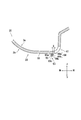
- FIG. 13 is an enlarged view of a cross-sectional view of the accommodating portion 30.
- the first rib 64 has an upper portion 64a and a lower portion 64b.
- the upper portion 64 a is a portion located on the upper side of the first rib 64.
- the lower portion 64 b is a portion located on the lower side of the first rib 64.
- the upper portion 64 a of the first rib 64 is continuous with the edge surface portion 62.
- the lower portion 64 b of the first rib 64 is continuous with the second rib 65.
- the lower end portion 65c of the second rib 65 is positioned below the lower end portion 64c of the first rib 64, or is positioned at substantially the same height as the lower end portion 64c of the first rib 64.
- the second rib 65 has a connecting surface 65a.
- the connecting surface 65a indicates a surface of the second rib 65 where the first rib 64 is continuous.
- the connection surface 65 a indicates a surface of the second rib 65 located at the front portion.
- the connection surface 65a extends along the left-right direction.
- the first rib 64 protrudes perpendicularly to the connecting surface 65a. Moreover, the protrusion amount X of the 1st rib 64 with respect to the connection surface 65a becomes small, so that it goes to the lower part of the connection surface 65a. As a result, the first rib 64 can effectively guide water droplets toward the second rib 65.
- FIG. 14 is a second cross-sectional view of the accommodating portion 30, the housing 1, and the base 7.
- the accommodating part 30 shown in FIG. 14 is XII-XII sectional drawing of the accommodating part 30 shown in FIG.
- the second drainage mechanism 70 has a second hole 71.
- the second hole 71 is a hole penetrating between the inner surface 3a and the outer surface 3b of the housing 30.
- the second hole 71 communicates the inside of the housing part 30 with the outside of the housing part 30.
- the second hole portion 71 protrudes downward from the housing portion 30.
- the second hole portion 71 protrudes downward from the second bottom portion 92 of the housing portion 30.
- the second hole 71 has a second opening 72.
- the second opening 72 is formed at the lower end of the second hole 71.
- the second opening 72 has a shape inclined at an angle ⁇ 1 with respect to the horizontal plane H when viewed in the horizontal direction.
- the angle ⁇ 1 is an angle other than 0 ° ( ⁇ 1 ⁇ 0).
- the second hole 71 is installed in a place where the second hole 71 does not overlap the bottom base 7 when viewed in the vertical direction. Accordingly, the water droplets falling from the second opening 72 are discharged to the outside of the washing machine 100 through the drainage channel R without being supplied to the bottom base 7.
- FIG. 15 is a third cross-sectional view of the accommodating portion 30, the housing 1, and the base 7.
- the accommodating part 30 shown in FIG. 15 is XIII-XIII sectional drawing of the accommodating part 30 shown in FIG.
- the second drainage mechanism 70 has a third hole 81.
- the third hole portion 81 is a hole that penetrates between the inner surface portion 3a and the outer surface portion 3b of the accommodating portion 30.
- the third hole portion 81 communicates the inside of the housing portion 30 with the outside of the housing portion 30.
- the third hole portion 81 protrudes downward from the housing portion 30.
- the third hole portion 81 protrudes downward from the third bottom portion 93 of the housing portion 30.
- the case 11a is disposed above the third hole 81.
- the case 11a is placed on the support base 393.
- the support base 393 is a protrusion that is installed on the third bottom portion 93.
- the third hole portion 81 can discharge water droplets supplied to the inside of the housing portion 30 to the outside of the housing portion 30.
- the third hole 81 has a third opening 82. Similar to the second opening 72, the third opening 82 has a shape inclined at an angle ⁇ 2 with respect to the horizontal plane H when viewed in the horizontal direction ( ⁇ 2 ⁇ 0). Therefore, it is possible to suppress water droplets discharged through the third hole 81 from staying in the third opening 82 due to surface tension. In addition, since the third opening 82 is inclined with respect to the horizontal plane, the spread of water at the lower end of the second hole 71 can be suppressed.
- the third hole 81 is installed in a place where the third hole 81 does not overlap the bottom base 7 when viewed in the vertical direction. Accordingly, the water droplets falling from the third opening 82 are discharged to the outside of the washing machine 100 through the drainage channel R without being supplied to the bottom base 7.
- the charging unit 11 and the pressing unit 40 may not be provided in the housing unit 30 (see FIG. 8). It is sufficient that at least one of the first drainage mechanism 60 to the third drainage mechanism 80 is provided in the storage unit 30.
- the first drainage mechanism 60 is provided on the first bottom portion 91.
- the 1st drainage mechanism 60 should just be provided in the bottom part 90.
- the first drainage mechanism 60 may be provided on the second bottom 92 and / or the third bottom 93, for example.
- the second drainage mechanism 70 is provided on the second bottom portion 92.
- the second drainage mechanism 70 only needs to be provided at the bottom 90.
- the second drainage mechanism 70 may be provided on the first bottom 91, for example.
- the installation location of the third drainage mechanism 80 is not limited to the installation location of the first embodiment, similarly to the second drainage mechanism 70.
- the accommodating part 30 is provided in the housing
- the accommodating part 30 may be provided in places other than the front part 1a in the housing
- FIG. Further, the accommodating portion 30 may be provided in the door 2.
- the accommodating portion 30 is formed so as to be recessed from the outer surface portion of the washing machine 100.
- the accommodating part 30 should just be formed in the washing machine 100.
- the accommodating part 30 may be formed so as to protrude from the outer surface part of the washing machine 100.
- the washing machine 100 of the first embodiment is a drum-type washing machine.
- the present invention is not limited to this.
- the washing machine 100 may be a vertical washing machine.
- the present invention can be used in the field of washing machines.
Landscapes
- Engineering & Computer Science (AREA)
- Textile Engineering (AREA)
- Detail Structures Of Washing Machines And Dryers (AREA)
- Main Body Construction Of Washing Machines And Laundry Dryers (AREA)
- Centrifugal Separators (AREA)
Abstract
洗濯機(100)は、洗濯物を洗濯する。洗濯機(100)は、収容部(30)を備える。収容部(30)には、外部機器(50)を収容可能である。収容部(30)は、連通孔部を有する。連通孔部は、第1孔部(61)と、第2孔部(71)と、第3孔部(81)とを含む。連通孔部は、収容部(30)の底部(90)に形成される。連通孔部は、収容部(30)に外部機器(50)が収容されている状態で、収容部(30)の内部と収容部(30)の外部とを連通する。
Description
本発明は、洗濯機に関する。
特許文献1に記載の洗濯機は、超音波振動子と、超音波振動ホーンと、給水管と、固定部材とから成る部分洗い装置を備える。超音波振動ホーンは、超音波振動子の超音波振動を増幅させる。給水管は、超音波振動ホーンの先端部へ給水する。
特許文献1に記載の洗濯機において、固定部材内に部分洗い装置が挿入されることで、固定部材に部分洗い装置が収容される。
しかし、特許文献1に記載された洗濯機では、ユーザーの利便性の観点において向上する余地がある。例えば、固定部材内に部分洗い装置が挿入されると、部分洗い装置のカバーが固定部材に係止される。カバーが固定部材に係止されると、固定部材(収容部)の下端開口が閉塞される。この状態で、固定部材の内部に水滴が流入すると、固定部材の内部に水滴が溜まる。しかし、固定部材の内部に水滴が溜まることを抑制したいとする要望があった。
本発明は、洗濯機に設けられた収容部に外部機器が収容された状態で、収容部の内部に水滴が溜まることを抑制することができる洗濯機を提供する。
本発明の第1の局面によれば、洗濯機は、洗濯物を洗濯する。洗濯機は、収容部を備える。収容部には、外部機器を収容可能である。前記収容部は、連通孔部を有する。連通孔部は、前記収容部の底部に形成される。前記連通孔部は、前記収容部に前記外部機器が収容されている状態で、前記収容部の内部と前記収容部の外部とを連通する。
本発明によれば、洗濯機に設けられた収容部に外部機器が収容された状態で、収容部の内部に水滴が溜まることを抑制することができる。
本発明の第1実施形態について、図面を参照しながら説明する。なお、図中、同一又は相当部分については同一の参照符号を付して説明を繰り返さない。
図1及び図2を参照して、本発明の第1実施形態に係る洗濯機100について説明する。図1は、ドア2が閉じた洗濯機100の斜視図である。図2は、ドア2が開いた洗濯機100の斜視図である。
図1及び図2に示すように、洗濯機100は、筐体1と、ドア2と、入力部3と、給水ホース接続部4と、排水ホース接続部5と、ヒンジ機構6と、底台7とを備える。
以下では、図1に示すように、ユーザーが通常の姿勢で入力部3を操作するときの洗濯機100に対するユーザーの位置を前方として、前後左右方向、及び上下方向を規定する。
筐体1は、中空の略四角柱形状を有する。筐体1は、前面部1aと、背面部1bと、一対の側面部1cと、天井面部1dとを有する。前面部1aは、背面部1bの前方に位置する。一対の側面部1cは、左右方向に互いに間隔を空けて配置される。一対の側面部1cのうちの1つは、前面部1aの左側部と、背面部1bの左側部とに連設される。一対の側面部1cのうちの他の1つは、前面部1aの右側部と、背面部1bの右側部とに連設される。天井面部1dは、前面部1aの上部と、背面部1bの上部と、一対の側面部1cの上部とに連設される。
底台7は、筐体1の下部に設けられる。底台7は、筐体1の下部を閉塞する。
筐体1は、開口部1eを含む。開口部1eは、筐体1の外面部に形成される。第1実施形態では、開口部1eは、前面部1aの外面部に形成される。開口部1eは、収容部30の入り口を構成する。収容部30の説明は後述する。
ドア2は、略板状の部材である。ドア2は、筐体1に回転可能に取り付けられる。ドア2は、前面部1aの前部に設置される。
図1において、洗濯機100のドア2が閉状態Aである。閉状態Aは、ドア2が閉じた状態を示す。図2において、洗濯機100のドア2が開状態Bである。開状態Bは、ドア2が開いた状態を示す。
図1及び図2に示すように、ドア2は、ヒンジ機構6を介して筐体1に回転可能に取り付けられる。ドア2が回転することで、ドア2の状態が閉状態Aと開状態Bとのいずれかに切り替わる。
ドア2は、表面部21aと、裏面部21bとを有する。表面部21aの裏側には、裏面部21bが位置する。ドア2が閉状態Aのとき、表面部21aは前方を向く。ドア2が閉状態Aのとき、裏面部21bは後方を向くと共に筐体1に対向する。
入力部3は、洗濯機100に対する指示を受け付ける。洗濯機100に対する指示は、例えば、洗濯機100が有する機能を使用するための指示である。入力部3は、例えば、操作キーを含む。ユーザーは、入力部3を介して、洗濯機100に対して、例えば、洗い運転、すすぎ運転、脱水運転、及び乾燥運転のような動作を指示する。
また、入力部3には、洗濯機情報表示部が含まれる。洗濯機情報表示部は、洗濯機100動作状況を示す情報を表示する。
入力部3は、ドア2の表面部21aに設置される。なお、入力部3が設置される場所は、特に限定されない。入力部3は、筐体1に設置されてもよい。
給水ホース接続部4には、給水ホース(不図示)が接続可能である。給水ホースは水栓に接続される。筐体1の内部Nには、給水ホースを介して、洗い運転、及びすすぎ運転のような洗濯運転時に使う水が供給される。筐体1の内部Nは、前面部1aと、背面部1bと、一対の側面部1cと、天井面部1dとで囲まれた空間を示す。
排水ホース接続部5には、排水ホース(不図示)が接続可能である。洗濯機100は、給水ホースを介して、洗濯運転で使われた水を筐体1の外部に排出する。
洗濯機100は、収容部30をさらに備える。
収容部30には、外部機器50を収容可能である。外部機器50は、洗濯機100とは別体である。外部機器50は、例えば、超音波ウォッシャー(登録商標)のような携帯型の洗濯機器である。なお、外部機器50は、収容部30に収容可能な物体であればよく、携帯型の洗濯機器に限定されない。
収容部30は、筐体1に形成される。第1実施形態では、収容部30は、筐体1の前面部1aに形成される。収容部30は、例えば、樹脂により形成される。収容部30は、筐体1の外面部から筐体1の内部N側に凹んだ形状を有する。収容部30は、開口部1eを介して洗濯機100の外部に連通する。従って、外部機器50が収容部30に収容される際、外部機器50は、開口部1eを介して筐体1の内部N側に挿入される。その結果、外部機器50が収容部30に収容された状態で、外部機器50が洗濯機100から出っ張ることを抑制できる。
また、外部機器50の出っ張りが抑制されるので、洗濯機100の設置スペースを確保する作業の困難性を低減することができる。
ドア2が閉状態Aのとき、ドア2が収容部30に対して前方から対向する。その結果、ドア2が閉状態Aのとき、収容部30がドア2で覆われる。これに対し、ドア2が開状態Bのとき、収容部30が露出する。その結果、ドア2が開状態Bのとき、収容部30に対して外部機器50を出し入れすることができる。
洗濯機100は、開口部8と、回転ドラム9と、水槽(不図示)とをさらに備える。
開口部8は、筐体1の内部Nと筐体1の外部とを連通する。開口部8は、筐体1に形成される。第1実施形態では、開口部8は、前面部1aに形成される。
ドア2は、開口部8を開閉する。ドア2が閉状態Aのとき、ドア2が開口部8に対向する。その結果、ドア2が閉状態Aのとき、開口部8がドア2で閉塞される。これに対し、ドア2が開状態Bのとき、開口部8が開放される。
回転ドラム9と、水槽とは、筐体1の内部Nに配置される。
回転ドラム9には、洗濯物を収容可能である。回転ドラム9は、回転可能に支持される。回転ドラム9は、開口部8に連通する。回転ドラム9は、本発明の洗濯槽の一例である。水槽は、回転ドラム9の外側に配置される。
洗濯物は、開口部8を介して回転ドラム9内に出し入れされる。回転ドラム9内に洗濯物、水、及び洗剤が収容された状態で、回転ドラム9が回転することで、洗濯物が洗濯される。
次に、図3を参照して、洗濯機100についてさらに説明する。図3は、収容部30に外部機器50が収容された洗濯機100の斜視図である。
図3に示すように、収容部30には、外部機器50が収容されている。収容部30に外部機器50が収容された状態において、外部機器50が前面部1aよりも後方に位置する。その結果、収容部30に外部機器50が収容された状態において、ドア2は、外部機器50と干渉することなく、閉状態A(図1参照)になることができる。
次に、図1、図4、及び図5を参照して、洗濯機100についてさらに説明する。図4は、洗濯機100を示すブロック図である。
図4に示すように、洗濯機100は、充電部11と、検知部12とをさらに備える。
充電部11は、外部機器50を充電するための充電電流を出力する。充電部11は、例えば、洗濯機100に供給された商用電源電圧から充電電流を生成する回路を含む。
検知部12は、外部機器50が収容部30に収容されているか否かを検知するセンサである。検知部12は、例えば、光電センサ、又はマイクロスイッチを含む。
洗濯機100は、表示部13をさらに備える。
表示部13は、外部機器50に関する情報を表示する。外部機器50に関する情報は、例えば、外部機器50の充電状況を示す情報、及び/又は、収容部30に外部機器50が収容されているか否かを示す情報を含む。表示部13は、例えば、LED(Light Emitting Diode)のような光源を含む。表示部13は、ドア2の表面部21aに設置される。
図4に示すように、洗濯機100は、記憶部14と、制御部15とをさらに備える。
記憶部14は、ROM(Read Only Memory)、及びRAM(Random Access Memory)のような主記憶装置(例えば、半導体メモリー)を含み、補助記憶装置(例えば、ハードディスクドライブ)をさらに含んでもよい。記憶部14は、制御部15によって実行される種々のコンピュータープログラムを記憶する。
制御部15は、CPU(Central Processing Unit)及びMPU(Micro Processing Unit)のようなプロセッサーを含む。制御部15は、洗濯機100の各要素を制御する。具体的には、制御部15のプロセッサーは、記憶部14に記憶されたコンピュータープログラムを実行することにより、入力部3と、充電部11と、検知部12と、表示部13と、記憶部14とを制御する。
次に、図5を参照して、収容部30について説明する。図5は、収容部30の第1の斜視図である。
図5は、収容機器51を示す。収容機器51は、収容部30に収容されている外部機器50である。
図5に示すように、収容機器51は、第1載置部51aと、第2載置部51bと、中間部51cとを有する。中間部51cは、第1載置部51aと第2載置部51bとの間に位置する。第1実施形態では、第1載置部51aは、収容機器51の右端部である。また、第1実施形態では、第2載置部51bは、収容機器51の左端部である。また、第1実施形態では、中間部51cは、収容機器51の左右中央部である。
収容部30は、第1被載置部31と、第2被載置部32と、凹み部33とを有する。
第1被載置部31と第2被載置部32とは、互いに間隔を空けて配置される。第1被載置部31には、収容機器51の第1載置部51aが載置される。第2被載置部32には、収容機器51の第2載置部51bが載置される。
凹み部33は、第1被載置部31と第2被載置部32との間に位置する。凹み部33は、収容機器51の一部と対向しつつ、収容機器51の一部との間に隙間Zを形成する。第1実施形態では、凹み部33は、収容機器51の中間部51cとの間に隙間Zを形成する。
次に、図5から図7を参照して、筐体1に対する収容部30の取り付け構造について説明する。
図6は、図3に示す収容部30の拡大図である。図7は、筐体1に対する収容部30の取り付け構造を示す筐体1と収容部30との端面図である。
図5から図7に示すように、収容部30は、突出端部34と、凸部35と、溝部36と、複数の第1係合部37と、複数の第2係合部38とをさらに有する。
突出端部34は、収容機器51の後部に位置する。突出端部34は、上方に突出する形状を有する。凸部35は、突出端部34の前方に位置する。凸部35は、上方に突出する形状を有する。溝部36は、突出端部34と凸部35との間に形成される隙間である。第2係合部38は、突出端部34に形成される。第2係合部38は、係合孔部38aを有する。
第1係合部37は、収容機器51の前部に位置する。第1係合部37は、略鉤状に形成される。複数の第1係合部37は、左右方向に間隔を空けて並んでいる。
筐体1は、下縁部1fと、内壁部1gとをさらに有する。
下縁部1fは、開口部1eのうち下側の縁部を示す。下縁部1fの裏側には、第1係合部37に係合可能な第1被係合部(不図示)が設けられる。第1係合部37は第1被係合部と係合する。その結果、収容機器51の前部が筐体1に取り付けられる。なお、下縁部1fの裏側は、下縁部1fのうち筐体1の内部N側を向く面を示す。
内壁部1gは、開口部1eから筐体1の内部N側に突出する。内壁部1gの先端部1hは、収容部30の溝部36に挿入される。その結果、収容空間Vが、筐体1の内部Nと仕切られる。収容空間Vは、開口部1eの内側に位置し、収容機器51が収容される空間を示す。
第2係合部38の係合孔部38aには、内壁部1gの背面1jに形成される係合突起(不図示)が挿入される。その結果、収容機器51の後部が筐体1に取り付けられる。
なお、筐体1に対する収容部30の取り付け構造は、第1実施形態の取り付け構造に限定されない。また、筐体1と収容部30とが一体で形成されてもよい。
次に、図2、及び図8から図9(b)を参照して、収容部30と外部機器50とについてさらに説明する。図8は、収容部30の平面図である。図9(a)は、収容部30に外部機器50を収容しているユーザーの動作を示す図である。図9(b)は、収容部30に収容された外部機器50を示す図である。
図8に示すように、収容部30は、第1設置部39aと、第2設置部39bとをさらに有する。
第1設置部39aは、収容部30のうち押圧部40を構成する部材が設置される箇所を示す。第1実施形態では、第1設置部39aは、第1被載置部31の右方に位置する。押圧部40の説明は後述する。
第2設置部39bは、収容部30のうち充電部11を構成する部材が設置される箇所を示す。第1実施形態では、第2設置部39bは、第2被載置部32の左方に位置する。
図8から図9(b)に示すように、充電部11は、ケース11aと、送電部11bとを有する。ケース11aは、送電部11bを収容する。送電部11bは、例えば、送電コイルを含む。ケース11aは、第2被載置部32に設置される。
外部機器50は、第1端部50aと、第2端部50bと、受電部52とを有する。外部機器50が収容部30に収容されたとき、第1端部50aと第2端部50bとは、互いに反対側に位置する。受電部52は、例えば、受電コイルを含む。受電部52は、第1端部50aに設置される。
図9(b)は、充電姿勢αの外部機器50を示す。充電姿勢αは、外部機器50の受電部52が、充電部11の送電部11bと対向する姿勢を示す。
外部機器50が収容部30に充電姿勢αで収容されることで、送電部11bから出力される電力を、受電部52が磁界を通じて無接点で受電する。その結果、外部機器50のバッテリ(不図示)が充電される。
図2、図8、及び図9(a)に示すように、洗濯機100は、押圧部40をさらに備える。
押圧部40は、第1被載置部31に設置される。
外部機器50は、押圧部40と送電部11bとの間に収容される。
押圧部40は、支持軸41と、回転部材42と、弾性部材43とを有する。
支持軸41は、収容部30に取り付けられる。支持軸41は、収容部30により回転可能に支持される。回転部材42は、第1被載置部31よりも上方に位置する。支持軸41は、第1被載置部31よりも右方に位置する。支持軸41は、前後方向に沿って延びる。
回転部材42は、板状の部材を屈曲させた形状を有する。回転部材42は、支持軸41に固定される。回転部材42は、支持軸41と共に回転する。また、回転部材42は、支持軸41を中心に回転する。回転部材42は、支持軸41を介して、収容部30により回転可能に支持される。
回転部材42は、基端部42aと、中間部42bと、先端部42cとを有する。
基端部42aは、回転部材42に取り付けられる。中間部42bは、基端部42aに連設される。中間部42bは、基端部42aから送電部11b側へ突出する。また、中間部42bは、水平方向よりも下側に向いて突出する。先端部42cは、中間部42bに連設される。先端部42cは、中間部42bから送電部11b側へ突出する。また、先端部42cは、中間部42bよりも下側に向いて突出する。
収容部30に外部機器50が収容されているとき(図9(b)参照)、回転部材42の先端部42cが外部機器50に接触する。
弾性部材43は、例えば、ねじりコイルばねである。弾性部材43は、収容部30に取り付けられる。また、弾性部材43は、回転部材42に取り付けられる。また、弾性部材43は、支持軸41に巻回される。
回転部材42に対して外力が作用していない状態で、回転部材42の中間部42b及び先端部42cが第1被載置部31の上方に位置する。
回転部材42に対して外力が作用していないときの方が(図9(a)参照)、収容部30に外部機器50が収容されているときよりも(図9(b)参照)、回転部材42の先端部42cが送電部11bに近接している。従って、収容部30に外部機器50が充電姿勢αで収容されているとき、弾性部材43の復元力が近接方向Wに発生する。近接方向Wは、外部機器50の充電部11が送電部11bに近接する方向を示す。
続いて、図9(a)及び図9(b)を参照して、収容部30に外部機器50が収容される手順について説明する。
図9(a)に示すように、ユーザーは、外部機器50を把持した状態で、回転部材42と送電部11bとの間に外部機器50を上方から挿入する。
ユーザーが外部機器50を回転部材42と送電部11bとの間に挿入する際、外部機器50が回転部材42の中間部42bに接触する。
外部機器50が回転部材42に接触すると、回転部材42が外部機器50から下向きの圧力を受ける。その結果、回転部材42が下方Y2に回転する。その結果、図9(b)に示すように、回転部材42と送電部11bとの間に外部機器50が上方から挿入されることで、外部機器50が収容部30に収容される。
外部機器50が収容部30に充電姿勢αで収容されることで、外部機器50が充電される。このとき、外部機器50に対して近接方向Wに圧力が作用するので、外部機器50を効果的に充電することが可能になる。
次に、図10を参照して、収容部30についてさらに説明する。図10は、収容部30の第2の斜視図である。
図10に示すように、収容部30は、底部90を有する。底部90は、収容部30の底を構成する部分を示す。
底部90は、第1底部91と、第2底部92と、第3底部93とを含む。第1底部91は、凹み部33の底を構成する部分示す。第2底部92は、第1設置部39aの底を構成する部分を示す。第3底部93は、第2設置部39bの底を構成する部分を示す。
収容部30の底部90には、第1孔部61と、第2孔部71と、第3孔部81とが形成される。以下では、第1孔部61~第3孔部81を総称して連通孔部と記載することがある。
収容状態Cにおいて(図5参照)、連通孔部は、収容部30の内部と収容部30の外部とを連通する。従って、収容状態Cにおいて、連通孔部は、収容部30の内部に流入した水滴を収容部30の外部に排出することができる。その結果、収容状態Cにおいて、収容部30の内部に水滴が溜まることを抑制することができる。なお、収容状態Cは、収容部30に外部機器50が収容されている状態を示す。
次に、図8、及び図10から図15を参照して、収容部30の水抜き構造について説明する。図11は、収容部30の第3の斜視図である。図12は、収容部30、筐体1、及び底台7の第1の断面図である。
図11及び図12に示すように、収容部30は、内面部3aと、外面部3bとを有する。
内面部3aは、収容部30のうち収容機器51側を向く面である。内面部3aで囲まれる空間には、外部機器50が収容される。
以下では、内面部3aで囲まれる空間を、収容部30の内部と記載することがある。
外面部3bは、内面部3aと背向する面を示す。外面部3bは、収容部30の外部に対向する。収容部30の外部は、収容部30の周囲に位置する空間を示す。第1実施形態では、収容部30は、筐体1の内部Nに配置される。従って、第1実施形態では、収容部30の外部は、筐体1の内部Nを示す。
図8に示すように、収容部30は、第1排水機構60と、第2排水機構70と、第3排水機構80とをさらに有する。
まず、図11及び図12を参照して、第1排水機構60について説明する。図12に示す収容部30は、図8に示す収容部30のXI―XI断面図である。
図11及び図12に示すように、第1排水機構60は、複数の第1孔部61を有する。複数の第1孔部61は、左右方向に沿って並んでいる。なお、第1孔部61の個数は限定されない。また、第1孔部61は1つでもよい。
以下では、複数の第1孔部61のうちの1つに着目して説明する。
第1孔部61は、収容部30の内面部3aと外面部3bとの間を貫通する孔である。
第1孔部61は、凹み部33の第1底部91に形成される。また、第1孔部61は、第1底部91のうちの前部に位置する。
第1孔部61は、縁面部62を有する。
縁面部62は、第1孔部61の縁を形成する面を示す。縁面部62は、内面部3aと外面部3bとの間に位置し、内面部3aと外面部3bとに連なる。
図12に示すように、収容状態Cにおいて、第1孔部61と外部機器50との間には、隙間Zが形成される。従って、収容状態Cにおいて、第1孔部61が閉塞されない。その結果、収容状態Cにおいて、第1孔部61が、収容部30の内部と収容部30の外部とを連通している。
図11及び図12に示すように、第1排水機構60は、リブ部材63をさらに有する。
リブ部材63は、収容部30から突出する。リブ部材63は、第1孔部61から収容部30の外面部3bに亘って設けられる。リブ部材63は、例えば、樹脂により形成される。リブ部材63は、収容部30と一体形成される。なお、リブ部材63が収容部30と別体であり、リブ部材63が収容部30に固定されてもよい。
リブ部材63は、複数の第1リブ64と、第2リブ65とを有する。
複数の第1リブ64は、それぞれ、複数の第1孔部61に設けられる。以下では、複数の第1リブ64のうちの1つに着目して説明する。
第1リブ64は、第1孔部61の縁面部62に形成される。第1リブ64は、縁面部62から下方向に延びる。下方向は、本発明の第1方向の一例である。
第2リブ65は、収容部30の外面部3bに形成される。好ましくは、第2リブ65は、収容部30の底部90(図10参照)の外面部3bに形成される。第1実施形態では、第2リブ65は、第1底部91の外面部3bに形成される。
第2リブ65は、第1孔部61の下側に位置する。第2リブ65は、左右方向に沿って延びる。左右方向は、本発明の第2方向の一例である。第2リブ65は、外面部3bから下方に突出する。従って、第2リブ65は、第2リブ65から下方に水滴を落下させることが可能である。
第1リブ64の延びる方向は、第2リブ65の延びる方向に対して垂直である。従って、第1リブ64は、第2リブ65に連なる。連なるとは、複数の別体の部材が互いに連結されること、及び、複数の部材が一体形成されることの両方の意味を含む。
第1リブ64は、略柱状に形成される。第1リブ64は、縁面部62と第2リブ65との各々に対し、同一の方向から対向する。第1実施形態では、第1リブ64は、縁面部62と第2リブ65との各々に対し、前方から対向する。
第2リブ65は、底台7よりも上方に設置される。また、第2リブ65は、底台7よりも前方に設置される。
収容部30の下方には、排水路Rが形成される。排水路Rは、洗濯機100の内部と洗濯機100の外部とを連通する。第1実施形態では、排水路Rは、底台7と筐体1との間に形成される隙間を示す。
上下方向に見て、第2リブ65が底台7と重ならない場所に、第2リブ65が設置される。従って、第2リブ65から落下した水滴が底台7に供給されることなく、排水路Rを介して洗濯機100の外部に排出される。
図3及び図11を参照して、収容部30の内部に流入した水滴が洗濯機100の外部に排出される原理について説明する。
図3に示すように、収容部30に外部機器50が収容された状態で、ユーザーが回転ドラム9内に洗濯物を出し入れする。この場合、収容部30の内部に水滴が流入することがある。
図12に示すように、収容部30の内部に流入した水滴は、第1孔部61を介して収容部30の外部に流出する。収容部30の外部に流出した水滴は、第1リブ64から第2リブ65を伝って流れる。そして、水滴は、第2リブ65から筐体1の内部Nに落下する。筐体1の内部Nに落下した水滴は、排水路Rを通って洗濯機100の外部に排出される。洗濯機100の外部に排出された水滴は、例えば、防水パン(不図示)に収容される。その結果、底台7に水が溜まることを抑制することができる。また、例えば、底台7に洗濯機100の電装部品が設置される場合、電装部品に水滴が付着することを抑制することができる。
以上、図3、図10、及び図12を参照して説明したように、リブ部材63は、第1孔部61から収容部30の底部90の外面部3bに亘って設けられる。従って、第1孔部61から流出した水滴が所定の場所に排出されないように、リブ部材63により水滴を誘導することが可能である。その結果、水滴が所定の場所に排出されることを抑制することができる。なお、所定の場所は、水滴の排出場所のうち、ユーザーが望まない排出場所を示す。第1実施形態の所定の場所は、底台7である。
次に、図13を参照して、リブ部材63についてさらに説明する。図13は、収容部30の断面図の拡大図である。
図13に示すように、第1リブ64は、上側部分64aと、下側部分64bとを有する。上側部分64aは、第1リブ64のうち上側に位置する部分である。下側部分64bは、第1リブ64のうち下側に位置する部分である。
第1リブ64の上側部分64aは、縁面部62に連なる。第1リブ64の下側部分64bは、第2リブ65に連なる。
第2リブ65の下端部65cは、第1リブ64の下端部64cよりも下方に位置し、又は、第1リブ64の下端部64cと略同じ高さに位置する。
第2リブ65は、連結面65aを有する。連結面65aは、第2リブ65のうち第1リブ64が連なる面を示す。第1実施形態では、連結面65aは、第2リブ65のうち前部に位置する面を示す。連結面65aは、左右方向に沿って延びる。
第1リブ64は、連結面65aに対して垂直に突出する。また、連結面65aの下部に向かう程、連結面65aに対する第1リブ64の突出量Xが小さくなる。その結果、第1リブ64は、第2リブ65に向けて水滴を効果的に誘導することが可能になる。
次に、図8及び図14を参照して、第2排水機構70について説明する。図14は、収容部30、筐体1、及び底台7の第2の断面図である。図14に示す収容部30は、図8に示す収容部30のXII―XII断面図である。
図8及び図14に示すように、第2排水機構70は、第2孔部71を有する。
第2孔部71は、収容部30の内面部3aと外面部3bとの間を貫通する孔である。第2孔部71は、収容部30の内部と収容部30の外部とを連通している。
第2孔部71は、収容部30から下方に突出する。第1実施形態では、第2孔部71は、収容部30の第2底部92から下方に突出する。
第2孔部71は、第2開口部72を有する。第2開口部72は、第2孔部71の下端に形成される。第2開口部72は、水平方向に見て水平面Hに対して角度θ1で傾斜した形状を有する。角度θ1は、0°以外の角度である(θ1≠0)。第2開口部72が水平面Hに対して傾斜することで、第2孔部71を介して排出される水滴が第2開口部72に表面張力により留まることを抑制することができる。その結果、収容部30の内部に流入した水滴を、第2孔部71及び第2開口部72を介して収容部30の外部に円滑に排出することができる。また、第2開口部72が水平面に対して傾斜することで、第2孔部71の下端での水の広がりを抑制することができる。
上下方向に見て、第2孔部71が底台7と重ならない場所に、第2孔部71が設置される。従って、第2開口部72から落下した水滴が底台7に供給されることなく、排水路Rを介して洗濯機100の外部に排出される。
次に、図8及び図15を参照して、第3排水機構80について説明する。図15は、収容部30、筐体1、及び底台7の第3の断面図である。図15に示す収容部30は、図8に示す収容部30のXIII―XIII断面図である。
図8及び図15に示すように、第2排水機構70は、第3孔部81を有する。
第3孔部81は、収容部30の内面部3aと外面部3bとの間を貫通する孔である。第3孔部81は、収容部30の内部と収容部30の外部とを連通する。
第3孔部81は、収容部30から下方に突出する。第1実施形態では、第3孔部81は、収容部30の第3底部93から下方に突出する。
第3孔部81の上方には、ケース11aが配置される。ケース11aは、支持台393に載置される。支持台393は、第3底部93に設置される突起である。
ケース11aが支持台393に載置されることで、ケース11aと第3底部93との間には隙間Z1が形成される。従って、第3孔部81がケース11aにより閉塞されることを防止できる。その結果、第3孔部81は、収容部30の内部に供給された水滴を収容部30の外部に排出することができる。
第3孔部81は、第3開口部82を有する。第3開口部82は、第2開口部72と同様に、水平方向に見て水平面Hに対して角度θ2で傾斜した形状を有する(θ2≠0)。従って、第3孔部81を介して排出される水滴が第3開口部82に表面張力により留まることを抑制することができる。また、第3開口部82が水平面に対して傾斜することで、第2孔部71の下端での水の広がりを抑制することができる。
上下方向に見て、第3孔部81が底台7と重ならない場所に、第3孔部81が設置される。従って、第3開口部82から落下した水滴が底台7に供給されることなく、排水路Rを介して洗濯機100の外部に排出される。
以上、図面(図1~図15)を参照しながら本発明の実施形態について説明した。但し、本発明は、上記の実施形態に限られるものではなく、その要旨を逸脱しない範囲で種々の態様において実施することが可能である(例えば、(1)~(5))。また、上記の実施形態に開示されている複数の構成要素を適宜組み合わせることによって、種々の発明の形成が可能である。例えば、実施形態に示される全構成要素から幾つかの構成要素を削除してもよい。図面は、理解しやすくするために、それぞれの構成要素を主体に模式的に示しており、図示された各構成要素の個数等は、図面作成の都合から実際とは異なる場合もある。また、上記の実施形態で示す各構成要素は一例であって、特に限定されるものではなく、本発明の効果から実質的に逸脱しない範囲で種々の変更が可能である。
(1)収容部30には、充電部11、及び押圧部40が設けられなくてもよい(図8参照)。収容部30には、第1排水機構60~第3排水機構80のうちの少なくとも1つが設けられていればよい。
(2)図10に示すように、第1実施形態では、第1排水機構60は、第1底部91に設けられる。しかし、本発明はこれに限定されない。第1排水機構60は、底部90に設けられていればよい。第2実施形態では、第1排水機構60は、例えば、第2底部92、及び/又は、第3底部93に設けられてもよい。
また、第1実施形態では、第2排水機構70は、第2底部92に設けられる。しかし、本発明はこれに限定されない。第2排水機構70は、底部90に設けられていればよい。第3実施形態では、第2排水機構70は、例えば、第1底部91に設けられてもよい。また、第3排水機構80の設置場所についても、第2排水機構70と同様に、第1実施形態の設置場所に限定されない。
(3)第1実施形態では、図2(a)に示すように、収容部30は、筐体1に前面部1aに設けられる。しかし、本発明はこれに限定されない。収容部30は、筐体1のうち前面部1a以外の場所に設けられてもよい。また、収容部30は、ドア2に設けられてもよい。
(4)第1実施形態では、収容部30は、洗濯機100の外面部から凹むように形成される。しかし、本発明はこれに限定されない。収容部30は、洗濯機100に形成されていればよい。例えば、収容部30は、洗濯機100の外面部から出っ張るように形成されてもよい。
(5)第1実施形態の洗濯機100は、ドラム式洗濯機である。しかし、本発明はこれに限定されない。第4実施形態では、洗濯機100は、縦型洗濯機でもよい。
本発明は、洗濯機の分野に利用可能である。
3b 外面部
30 収容部
33 凹み部
50 外部機器
61 第1孔部
62 縁面部
63 リブ部材
64 第1リブ
64a 上側部分
64b 下側部分
65 第2リブ
65a 連結面
71 第2孔部
81 第3孔部(第2孔部)
90 底部
100 洗濯機
H 水平面
Z 隙間
30 収容部
33 凹み部
50 外部機器
61 第1孔部
62 縁面部
63 リブ部材
64 第1リブ
64a 上側部分
64b 下側部分
65 第2リブ
65a 連結面
71 第2孔部
81 第3孔部(第2孔部)
90 底部
100 洗濯機
H 水平面
Z 隙間
Claims (8)
- 洗濯物を洗濯する洗濯機であって、
外部機器を収容可能な収容部を備え、
前記収容部は、前記収容部の底部に形成される連通孔部を有し、
前記連通孔部は、前記収容部に前記外部機器が収容されている状態で、前記収容部の内部と前記収容部の外部とを連通する、洗濯機。 - 前記収容部は、前記収容部から突出するリブ部材を有し、
前記連通孔部は、第1孔部を有し、
前記リブ部材は、前記第1孔部から前記収容部の外面部に亘って設けられる、請求項1に記載の洗濯機。 - 前記リブ部材は、
前記第1孔部の縁面部から第1方向に延びる第1リブと、
前記外面部に形成され、前記第1方向と異なる第2方向に沿って延びる第2リブと
を有し、
前記第1リブが前記第2リブに連なる、請求項2に記載の洗濯機。 - 前記第2リブは、前記外面部から下方に突出し、
前記第1リブの上側部分が前記縁面部に連なり、
前記第1リブの下側部分が前記第2リブに連なる、請求項3に記載の洗濯機。 - 前記第2リブは、前記第1リブが連なる連結面を有し、
前記第1リブが前記連結面に対して垂直に突出する、請求項3又は請求項4に記載の洗濯機。 - 前記連結面の下部に向かう程、前記連結面に対する前記第1リブの突出量が小さくなる、請求項5に記載の洗濯機。
- 前記収容部は、収容機器の一部と対向しつつ前記収容機器の一部との間に隙間を形成する凹み部を有し、
前記収容機器は、前記収容部に収容されている前記外部機器を示し、
前記第1孔部が前記凹み部に形成される、請求項2から請求項6のいずれか1項に記載の洗濯機。 - 前記連通孔部は、前記収容部から下方に突出する第2孔部をさらに有し、
前記第2孔部の下端には開口部が形成され、
前記開口部は、水平方向に見て水平面に対して傾斜した形状を有する、請求項1から請求項7のいずれか1項に記載の洗濯機。
Priority Applications (2)
| Application Number | Priority Date | Filing Date | Title |
|---|---|---|---|
| JP2020521027A JP7225223B2 (ja) | 2018-05-24 | 2019-02-20 | 洗濯機 |
| CN201980033059.1A CN112135938B (zh) | 2018-05-24 | 2019-02-20 | 洗衣机 |
Applications Claiming Priority (2)
| Application Number | Priority Date | Filing Date | Title |
|---|---|---|---|
| JP2018-099690 | 2018-05-24 | ||
| JP2018099690 | 2018-05-24 |
Publications (1)
| Publication Number | Publication Date |
|---|---|
| WO2019225083A1 true WO2019225083A1 (ja) | 2019-11-28 |
Family
ID=68616617
Family Applications (1)
| Application Number | Title | Priority Date | Filing Date |
|---|---|---|---|
| PCT/JP2019/006363 Ceased WO2019225083A1 (ja) | 2018-05-24 | 2019-02-20 | 洗濯機 |
Country Status (4)
| Country | Link |
|---|---|
| JP (1) | JP7225223B2 (ja) |
| CN (1) | CN112135938B (ja) |
| TW (1) | TWI816753B (ja) |
| WO (1) | WO2019225083A1 (ja) |
Cited By (1)
| Publication number | Priority date | Publication date | Assignee | Title |
|---|---|---|---|---|
| CN114763662A (zh) * | 2021-01-12 | 2022-07-19 | 宝山钢铁股份有限公司 | 一种用于洗衣机外壳的侧板及洗衣机外壳 |
Citations (7)
| Publication number | Priority date | Publication date | Assignee | Title |
|---|---|---|---|---|
| JPS5914381U (ja) * | 1982-07-16 | 1984-01-28 | シャープ株式会社 | 洗濯機のモ−タ取付装置 |
| JPH07185191A (ja) * | 1993-12-27 | 1995-07-25 | Toshiba Corp | 脱水兼用洗濯機 |
| JPH0810492A (ja) * | 1994-06-30 | 1996-01-16 | Toshiba Corp | 脱水兼用洗濯機 |
| JPH09248400A (ja) * | 1996-03-15 | 1997-09-22 | Mitsubishi Electric Corp | 洗濯機 |
| JP2000308788A (ja) * | 1999-04-28 | 2000-11-07 | Sharp Corp | 部分洗い装置付き洗濯機 |
| JP2002360499A (ja) * | 2001-06-04 | 2002-12-17 | Zojirushi Corp | 食器乾燥器の食器かご |
| JP2003513797A (ja) * | 1999-11-16 | 2003-04-15 | ザ、プロクター、エンド、ギャンブル、カンパニー | 超音波器具 |
Family Cites Families (3)
| Publication number | Priority date | Publication date | Assignee | Title |
|---|---|---|---|---|
| TW293854B (ja) * | 1993-12-27 | 1996-12-21 | Toshiba Co Ltd | |
| FR3036120B1 (fr) * | 2015-05-13 | 2017-05-12 | Seb Sa | Appareil electromenager de repassage comportant un fer a repasser comprenant une semelle et une poignee disposee en porte a faux par rapport a la semelle |
| KR101729107B1 (ko) * | 2015-08-04 | 2017-04-21 | 엘지전자 주식회사 | 의류처리장치 |
-
2019
- 2019-02-20 JP JP2020521027A patent/JP7225223B2/ja active Active
- 2019-02-20 WO PCT/JP2019/006363 patent/WO2019225083A1/ja not_active Ceased
- 2019-02-20 CN CN201980033059.1A patent/CN112135938B/zh active Active
- 2019-02-26 TW TW108106576A patent/TWI816753B/zh active
Patent Citations (7)
| Publication number | Priority date | Publication date | Assignee | Title |
|---|---|---|---|---|
| JPS5914381U (ja) * | 1982-07-16 | 1984-01-28 | シャープ株式会社 | 洗濯機のモ−タ取付装置 |
| JPH07185191A (ja) * | 1993-12-27 | 1995-07-25 | Toshiba Corp | 脱水兼用洗濯機 |
| JPH0810492A (ja) * | 1994-06-30 | 1996-01-16 | Toshiba Corp | 脱水兼用洗濯機 |
| JPH09248400A (ja) * | 1996-03-15 | 1997-09-22 | Mitsubishi Electric Corp | 洗濯機 |
| JP2000308788A (ja) * | 1999-04-28 | 2000-11-07 | Sharp Corp | 部分洗い装置付き洗濯機 |
| JP2003513797A (ja) * | 1999-11-16 | 2003-04-15 | ザ、プロクター、エンド、ギャンブル、カンパニー | 超音波器具 |
| JP2002360499A (ja) * | 2001-06-04 | 2002-12-17 | Zojirushi Corp | 食器乾燥器の食器かご |
Cited By (2)
| Publication number | Priority date | Publication date | Assignee | Title |
|---|---|---|---|---|
| CN114763662A (zh) * | 2021-01-12 | 2022-07-19 | 宝山钢铁股份有限公司 | 一种用于洗衣机外壳的侧板及洗衣机外壳 |
| CN114763662B (zh) * | 2021-01-12 | 2023-08-11 | 宝山钢铁股份有限公司 | 一种用于洗衣机外壳的侧板及洗衣机外壳 |
Also Published As
| Publication number | Publication date |
|---|---|
| CN112135938A (zh) | 2020-12-25 |
| TWI816753B (zh) | 2023-10-01 |
| CN112135938B (zh) | 2023-02-28 |
| JPWO2019225083A1 (ja) | 2021-05-27 |
| JP7225223B2 (ja) | 2023-02-20 |
| TW202003962A (zh) | 2020-01-16 |
Similar Documents
| Publication | Publication Date | Title |
|---|---|---|
| US11814779B2 (en) | Washing machine | |
| CN113355852A (zh) | 衣物处理装置 | |
| JP3927542B2 (ja) | 洗濯機の洗剤投入装置 | |
| KR101880083B1 (ko) | 세탁기 | |
| WO2019225083A1 (ja) | 洗濯機 | |
| JP5816515B2 (ja) | ドラム式洗濯機 | |
| KR102694109B1 (ko) | 센서모듈 및 이를 구비한 의류처리장치 | |
| WO2019225093A1 (ja) | 洗濯機 | |
| JP6742361B2 (ja) | 洗濯機 | |
| JP7492570B2 (ja) | 洗濯機 | |
| US20180363217A1 (en) | Wall-mounted washing machine, detergent container of wall-mounted washing machine, and front panel of wall-mounted washing machine | |
| US7874186B2 (en) | Abnormal vibration sensing apparatus and washing machine having the same | |
| CN113279198A (zh) | 衣物处理装置 | |
| KR101161374B1 (ko) | 세탁기의 리드 마그네트 고정구조 | |
| US20180363221A1 (en) | Wall-mounted washing machine and detergent container thereof | |
| JP7633122B2 (ja) | 衣類処理装置 | |
| JP4958747B2 (ja) | 洗濯機 | |
| KR100465698B1 (ko) | 세탁기의 마그네트 고정구조 | |
| US20190338454A1 (en) | Multi-purpose cleaning device | |
| KR101225969B1 (ko) | 상업용 세정장치의 카드 리더 | |
| JP2021194224A (ja) | 衣類処理装置 | |
| KR20030060546A (ko) | 드럼 세탁기의 컨트롤 패널 조립구조 | |
| KR20050079776A (ko) | 드럼세탁기의 세제박스 조립구조 | |
| KR20070059415A (ko) | 세탁기의 전선 다발 고정구조 |
Legal Events
| Date | Code | Title | Description |
|---|---|---|---|
| 121 | Ep: the epo has been informed by wipo that ep was designated in this application |
Ref document number: 19807981 Country of ref document: EP Kind code of ref document: A1 |
|
| ENP | Entry into the national phase |
Ref document number: 2020521027 Country of ref document: JP Kind code of ref document: A |
|
| NENP | Non-entry into the national phase |
Ref country code: DE |
|
| 122 | Ep: pct application non-entry in european phase |
Ref document number: 19807981 Country of ref document: EP Kind code of ref document: A1 |