WO2019220980A1 - 伝送システム及び波長リソース管理方法 - Google Patents
伝送システム及び波長リソース管理方法 Download PDFInfo
- Publication number
- WO2019220980A1 WO2019220980A1 PCT/JP2019/018390 JP2019018390W WO2019220980A1 WO 2019220980 A1 WO2019220980 A1 WO 2019220980A1 JP 2019018390 W JP2019018390 W JP 2019018390W WO 2019220980 A1 WO2019220980 A1 WO 2019220980A1
- Authority
- WO
- WIPO (PCT)
- Prior art keywords
- wavelengths
- information
- transmission function
- optical fiber
- function device
- Prior art date
- Legal status (The legal status is an assumption and is not a legal conclusion. Google has not performed a legal analysis and makes no representation as to the accuracy of the status listed.)
- Ceased
Links
Images




Classifications
-
- H—ELECTRICITY
- H04—ELECTRIC COMMUNICATION TECHNIQUE
- H04B—TRANSMISSION
- H04B10/00—Transmission systems employing electromagnetic waves other than radio-waves, e.g. infrared, visible or ultraviolet light, or employing corpuscular radiation, e.g. quantum communication
- H04B10/27—Arrangements for networking
-
- H—ELECTRICITY
- H04—ELECTRIC COMMUNICATION TECHNIQUE
- H04J—MULTIPLEX COMMUNICATION
- H04J14/00—Optical multiplex systems
- H04J14/02—Wavelength-division multiplex systems
- H04J14/0201—Add-and-drop multiplexing
- H04J14/0215—Architecture aspects
- H04J14/0219—Modular or upgradable architectures
-
- G—PHYSICS
- G02—OPTICS
- G02B—OPTICAL ELEMENTS, SYSTEMS OR APPARATUS
- G02B6/00—Light guides; Structural details of arrangements comprising light guides and other optical elements, e.g. couplings
- G02B6/24—Coupling light guides
- G02B6/26—Optical coupling means
- G02B6/28—Optical coupling means having data bus means, i.e. plural waveguides interconnected and providing an inherently bidirectional system by mixing and splitting signals
- G02B6/293—Optical coupling means having data bus means, i.e. plural waveguides interconnected and providing an inherently bidirectional system by mixing and splitting signals with wavelength selective means
- G02B6/29379—Optical coupling means having data bus means, i.e. plural waveguides interconnected and providing an inherently bidirectional system by mixing and splitting signals with wavelength selective means characterised by the function or use of the complete device
- G02B6/2938—Optical coupling means having data bus means, i.e. plural waveguides interconnected and providing an inherently bidirectional system by mixing and splitting signals with wavelength selective means characterised by the function or use of the complete device for multiplexing or demultiplexing, i.e. combining or separating wavelengths, e.g. 1xN, NxM
-
- H—ELECTRICITY
- H04—ELECTRIC COMMUNICATION TECHNIQUE
- H04J—MULTIPLEX COMMUNICATION
- H04J14/00—Optical multiplex systems
- H04J14/02—Wavelength-division multiplex systems
- H04J14/0227—Operation, administration, maintenance or provisioning [OAMP] of WDM networks, e.g. media access, routing or wavelength allocation
-
- H—ELECTRICITY
- H04—ELECTRIC COMMUNICATION TECHNIQUE
- H04J—MULTIPLEX COMMUNICATION
- H04J14/00—Optical multiplex systems
- H04J14/02—Wavelength-division multiplex systems
- H04J14/0227—Operation, administration, maintenance or provisioning [OAMP] of WDM networks, e.g. media access, routing or wavelength allocation
- H04J14/0254—Optical medium access
- H04J14/0256—Optical medium access at the optical channel layer
-
- H—ELECTRICITY
- H04—ELECTRIC COMMUNICATION TECHNIQUE
- H04L—TRANSMISSION OF DIGITAL INFORMATION, e.g. TELEGRAPHIC COMMUNICATION
- H04L12/00—Data switching networks
- H04L12/28—Data switching networks characterised by path configuration, e.g. LAN [Local Area Networks] or WAN [Wide Area Networks]
- H04L12/46—Interconnection of networks
Definitions
- the present invention relates to a disaggregation-type transmission system and a wavelength resource management method in which bases having various transmission function devices having functions necessary for data transmission of different vendor specifications are connected by optical fibers.
- the all-in-one transmission system 10 shown in FIG. 8 is mainly applied at present.
- a plurality of TRDs (Transponders) 13 a and 13 b and an OXC (optical cross-connect) 14 are provided in each of the two A buildings (buildings) 11 and B 12.
- the OXCs 14 of the B building 12 are connected by an optical fiber 15.
- the transmission system 10 is configured by connecting the TRDs 13a and 13b and the OXC 14 of the A building 11 and the B building 12 with optical fibers 15a and 15b.
- all TRDs 13 a and 13 b and OXC 14 of the A building 11 and the B building 12 have the same vendor V specification.
- the OXC 14 is a device that can freely set an optical communication path for data transmission in the optical fiber 15 by switching. This OXC 14 can output a data signal to another path even when there is a data transmission path having a different format for each communication application or transmission speed.
- the TRDs 13a and 13b are relay devices connected to communication devices such as personal computers (PCs), routers, and switches (not shown), and desired communication devices are connected to the A building 11 and the B building 12 via the TRDs 13a and 13b. Communication between them is possible.
- PCs personal computers
- routers routers
- switches switches
- OTT Over The Top
- SNS social networking service
- Disaggregation type transmission system is a flexible and quick communication service by combining various functions such as transport function, WDM (Wavelength Division Multiplexing) function, switch function, and access function, which are all-in-one components. It is a configuration to provide.
- WDM Widelength Division Multiplexing
- FIG. 9 shows a configuration example of the disaggregation type transmission system 20.
- a plurality of TRDs 13a, 13b, a MUX (Multiplexer) / DMUX (DeMUX) 21, and a ROADM (Reconfigurable Optical Add / Drop Multiplexer) 22 are provided in each of the A building 11 and the B building 12.
- the ROADMs 22 of the A building 11 and the B building 12 are connected by an optical fiber 15.
- the TRDs 13a and 13b and the MUX / DMUX 21 are connected by optical fibers 15a and 15b
- the MUX / DMUX 21 and the ROADM 22 are connected by an optical fiber 15c.
- Both the MUX / DMUX 21 and the ROADM 22 have a function corresponding to the OXC 14.
- the TRD 13a has a vendor V1 specification
- the MUX / DMUX 21 has a vendor V2 specification
- the ROADM 22 has a vendor V3 specification.
- the MUX in the MUX / DMUX 21 multiplexes a plurality of signals and outputs them as one signal, and the DMUX branches one signal and outputs it as a plurality of signals.
- the ROADM 22 performs multiplexing processing by branching or inserting the optical signal as it is.
- the ROADM 22 has substantially the same function as a WDM (wavelength division multiplexing) function for simultaneously placing a plurality of optical signals having different wavelengths on one optical fiber.
- Non-Patent Document 1 An example of a disaggregation type transmission system is disclosed in Non-Patent Document 1.
- Non-Patent Document 2 describes an example of the contents of the disaggregation type operation status.
- an example of the all-in-one type transmission system 10 is described in Non-Patent Document 3.
- Non-Patent Document 4 describes an example of a wavelength resource of 32 wavelengths of an optical fiber that connects two bases in an all-in-one type or disaggregation type transmission system.
- the TRDs 13a and 13b, the MUX / DMUX 21, and the ROADM 22 have different vendor specifications. For this reason, it becomes difficult to grasp the wavelength resources that can be accommodated in the optical fiber 15 that connects the ROADMs 22 of the A building 11 and the B building 12, and there is a problem that the wavelength resources cannot be easily managed.
- the present invention has been made in view of such circumstances, and in a disaggregation type transmission system in which bases having various transmission function devices of different vendor specifications are connected by optical fibers, It is an object of the present invention to provide a transmission system and a wavelength resource management method that can easily grasp and manage the wavelength resources that can be accommodated.
- the invention according to claim 1 is a disaggregation type transmission system in which bases having various transmission function devices of different vendor specifications are connected by optical fibers, Specific information for each of the transmission function devices, connection information between the transmission function devices, and information on the number of wavelengths as wavelength resources that can be accommodated determined by the number of wavelengths of the transmission function device in the optical fiber between the bases.
- a DB that stores facility information as DB (Data Base) information, and the number of wavelengths of order information for requesting the number of wavelengths necessary for transmitting an optical signal between the bases via an optical fiber are the DB information.
- the facility information of each transmission function device that includes the DB information and is stored
- the invention according to claim 3 is a wavelength resource management method by a disaggregation type transmission system in which bases having various transmission function devices of different vendor specifications are connected by an optical fiber, wherein the transmission system includes at least Specific information for each of the transmission function devices, connection information between the transmission function devices, and information on the number of wavelengths as wavelength resources that can be accommodated determined by the number of wavelengths of the transmission function device in the optical fiber between the bases.
- a DB that stores facility information as DB information, a design unit, and a setting unit are provided, and the design unit requests the number of wavelengths necessary for transmitting an optical signal between the bases via an optical fiber.
- the DB information is included and stored in the DB. And executing the step of designing the number of wavelengths for each transmission function device necessary to enable the number of wavelengths of the order information to be accommodated in the optical fiber based on the facility information of each transmission function device that is set, Is a wavelength resource management method characterized by executing a step of setting the designed number of wavelengths in the corresponding transmission function device.
- the wavelength resource necessary for transmission of the optical signal between the bases via the optical fiber requested by the order information is automatically set in the transmission function apparatus for each base. be able to. Therefore, in the disaggregation type transmission system, it is possible to easily grasp and manage the wavelength resources that can be accommodated in the optical fiber.
- the design unit can accommodate the number of wavelengths for each transmission function device according to the design in the optical fiber when all of the transmission function devices stored in the DB are used.
- wavelength resources that can be accommodated in the optical fiber can be easily grasped.
- a transmission system and a wavelength resource management method that can be managed can be provided.
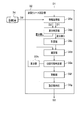
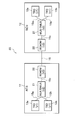
- FIG. 1 is a block diagram showing a configuration of a disaggregation type transmission system according to an embodiment of the present invention.
- the transmission system 30 shown in FIG. 1 parts corresponding to those of the conventional transmission system 20 shown in FIG.
- the disaggregation type transmission system 30 shown in FIG. 1 is used as various transmission function devices having functions necessary for data transmission (data transmission / reception) provided in each of the A building 11 and the B building 12 which are communication bases. It has TRD13, MUX / DMUX21 and ROADM22. Further, the transmission system 30 includes a service order acquisition unit (also referred to as an acquisition unit) 31, a wavelength resource design unit (also referred to as a design unit) 32, and a wavelength resource setting unit (also referred to as a setting unit) that are characteristic elements of the present embodiment. ) 33 and a facility DB (Data Base) 34.
- a service order acquisition unit also referred to as an acquisition unit
- a wavelength resource design unit also referred to as a design unit
- a wavelength resource setting unit also referred to as a setting unit
- TRD13 has different vendor specifications, such as vendor V1 specifications, MUX / DMUX21 has vendor V2 specifications, and ROADM 22 has vendor V3 specifications.
- the acquisition unit 31, the design unit 32, the setting unit 33, and the facility DB 34 may be individually configured with devices, or may be configured with one device including all of them.
- equipment DB34 comprises DB as described in a claim.
- the acquisition unit 31 is configured based on BSS (Business Support Systems) that supports business aspects such as user management.
- BSS Business Support Systems
- the acquisition unit 31 receives and acquires a service order (described later) from the user.
- the service order is an application for setting a transmission path, for example, using one optical signal with a wavelength of 10 GHz in the section between the ROADM 22 of the A building 11 and the ROADM 22 of the B building 12 (also referred to as an AB section or between bases). It is a request.
- the design unit 32 is configured based on OSS (Operation Support Systems) that supports network operation.
- the design unit 32 includes an optical fiber in which the number of wavelengths in the order information for requesting the number of wavelengths required when transmitting an optical signal through the optical fiber 15 in the AB section is included in DB information D2 described later. If the number of wavelengths that can be accommodated in the optical fiber 15 is greater than the number of wavelengths that can be accommodated in the optical fiber 15, the number of wavelengths of the TRD 13, MUX / DMUX 21, and ROADM 22 that are necessary to obtain the number of wavelengths that can be accommodated in the optical fiber 15 is designed.
- the design unit 32 includes an information acquisition unit 32a, a difference determination unit 32b, a calculation unit 32c, a determination unit 32d, an accommodability determination unit 32e, an update unit 32f, and a setting instruction unit 32g. And a display unit 32h.
- the information acquisition unit 32a acquires service order information (also referred to as order information) D1 received and acquired by the acquisition unit 31 (FIG. 1), and DB information D2 described later stored in the facility DB 34.
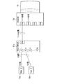
- the DB information D2 includes building specific information such as names of the A building 11 and the B building 12 in the transmission system 30 stored in the facility DB 34, floor information, unique information of each transmission function device such as the TRD 13, the MUX / DMUX 21 and the ROADM 22, It includes equipment information such as information on ports (described later) of each transmission function device, connection information of each transmission function device, and wavelength number information. Further, the DB information D2 is information including information on the number of wavelengths as wavelength resources that can be accommodated in the optical fiber 15 in the AB section.
- the DB information D2 is a collection of facility information in the A building 11 shown in FIG. 3 and facility information in the B building 12 (not shown) based on the previous order information D1. Note that the facility information of the A building 11 and the B building 12 is assumed to be the same, and therefore, the A building 11 will be described as a representative. However, the DB information D2 stores facility information of various transmission function devices constituting each base in addition to the current DB information D2.
- “A” of building A 11 shown in FIG. 3 is the building name. Although floor information is not necessarily required, it is assumed here that “10F” is on the 10th floor.
- the unique information of TRD is “13a”, “13b”, “13c”, “13d”,..., “13j” for 12 units
- the unique information of MUX / DMUX is “21a” for 2 units
- “21b” and the ROADM specific information is “22” for one vehicle.
- Each TRD 13a to 13j includes one port P for inputting / outputting an optical signal. However, although not shown, each TRD 13a to 13j is provided with a port for inputting / outputting a data signal to / from the user terminal on the opposite side of the port P.
- the MUX / DMUX 21a, 21b includes, for example, 16 ports P on one input / output side on the TRD side and a set of 16 ports P16 on the other input / output side on the ROADM side.
- the ROADM 22 includes, for example, four sets of 16 ports P16 on the MUX / DMUX side, and an optical fiber 15 is connected to the opposite side of the port P16.
- the two TRDs 13a and 13b are connected to the two ports P1 and P2 of one MUX / DMUX 21a, and the port P16 on the opposite side of the MUX / DMUX 21a is connected to the port P16 of the ROADM 22.
- the ten TRDs 13c to 13j are connected to the ten first ports P1 to P10 of the other MUX / DMUX 21b, and the port P16 of the MUX / DMUX 21b is connected to the second port P16 of the ROADM 22. Yes.
- the third and fourth ports P16 of the ROADM 22 are not connected.
- Ports P3 to P16 of one MUX / DMUX 21a are also in a non-connected state, and ports P11 (not shown) to P16 of the other MUX / DMUX 21b are also in a non-connected state.
- TRDs 13a to 13j have 12 wavelengths
- MUX / DMUXs 21a and 21b have 32 wavelengths
- ROADM 22 has 32 wavelengths. Twelve wavelengths are the wavelength resources (number of wavelengths) that can be accommodated in the optical fiber 15.
- FIGS. Other examples of equipment configuration are shown in FIGS.
- TRDs 13a and 13b have two wavelengths
- MUX / DMUX 21c has 24 wavelengths
- ROADM 22 has 16 wavelengths
- the wavelength resources (wavelengths) that can accommodate the smallest two wavelengths of TRDs 13a and 13b in the optical fiber 15 are as follows. Number).
- the TRDs 13a to 13x are 24 wavelengths
- the MUX / DMUX 21c is 24 wavelengths
- the ROADM 22 is 16 wavelengths.
- the wavelength resource (number of wavelengths) that can accommodate the smallest 16 wavelengths of the ROADM 22 in the optical fiber 15 It becomes.
- the difference determination unit 32b shown in FIG. 2 determines whether or not there is a difference between the order information D1 and the DB information D2. However, if the DB information D2 is the equipment configuration information shown in FIG. 3, the DB information D2 includes the ROADM 22 with 32 wavelengths, the MUX / DMUXs 21a and 21b with 32 wavelengths, the TRDs 13a to 13j with 12 wavelengths, and the optical fiber 15. This is information indicating the 12 wavelengths that can be accommodated.
- the order information D1 has 12 wavelengths that can be transmitted by the 12 TRDs 13a to 13j of the A building 11 shown in FIG. 3 and the 12 TRDs (not shown) of the B building 12 in the AB section. Assume that this is network setting request information indicating that a wavelength resource is to be used.
- the difference determination unit 32b determines that there is no difference. In addition, it is determined that there is no difference even when the number of wavelengths of the order information D1 is smaller than the number of wavelengths of the DB information D2.
- the order information D1 is request information indicating that it is desired to use wavelength resources of 16 wavelengths that can be transmitted by 16 TRDs in the AB section.
- the difference determination unit 32b determines that the order information D1 has a difference of 4 wavelengths more.
- the calculation unit 32c illustrated in FIG. 2 obtains the number of wavelengths (wavelength resources) that can be accommodated in the optical fiber based on the order information D1 when the difference determination unit 32b determines that there is a difference in which the order information D1 has four wavelengths more.
- the number of wavelengths required for each transmission function device is calculated.
- the number of wavelengths necessary for each transmission function device to obtain the number of 16 wavelengths that can be transmitted by 16 TRDs is calculated as follows.
- the calculation unit 32c first acquires the unique information of each transmission function device and counts the number of each transmission function device. Next, the connection configuration of each transmission function device is acquired. Next, the port P of each transmission function device is acquired and the number of ports is totaled. Next, the number of wavelengths of each transmission function device is tabulated.
- the calculation unit 32c calculates the number of wavelengths necessary for each transmission function device to obtain 16 wavelengths that can be accommodated in the optical fiber in the AB section with 16 TRDs based on the order information D1. In this case, first, the calculation unit 32c totals the numbers of TRD, MUX / DMUX, and ROADM as transmission function devices necessary for obtaining 16 wavelengths based on the order information D1. Next, the calculation unit 32c calculates the aggregated TRD, MUX / DMUX, and ROADM connection configuration. Next, the calculation unit 32c counts the number of TRD, MUX / DMUX, and ROADM ports used in the connection configuration.
- the calculation unit 32c calculates the number of wavelengths that can be accommodated in TRD, MUX / DMUX, and ROADM based on the total number of ports. Accordingly, 16 wavelengths of TRD, 32 wavelengths of MUX / DMUX, and 32 wavelengths of ROADM are calculated. Among the calculated numbers of wavelengths, 16 wavelengths that can be accommodated in the optical fiber 15 in the AB section are determined according to the smallest 16 wavelengths of TRD.
- the determination unit 32d determines the current wavelength resource indicated by the DB information D2.
- the accommodability determination unit 32e is configured such that the number of wavelengths of each transmission function device determined by the determination unit 32d and the number of wavelengths of the optical fiber 15 between the bases are the light between the current transmission function devices and the bases included in the DB information D2. It is determined whether or not the fiber 15 can be accommodated.
- the determination unit 32d determines that the number of wavelengths of each transmission function device determined by the determination unit 32d can be accommodated by each of the current transmission function devices included in the DB information D2, and at this time, the maximum capacity that the optical fiber 15 can accommodate is determined. Assuming that the number of wavelengths is 16, out of 16 wavelengths, 12 wavelengths related to the DB information D2 are in use, and there are four remaining wavelengths. Therefore, since the difference determination unit 32 b has already determined that there is a difference of four wavelengths, the four wavelengths can be accommodated in the remaining four wavelength bands of the optical fiber 15.
- the number of wavelengths determined by the determination unit 32d is the number of wavelengths when the difference determination unit 32b determines that there is no difference, it is determined that accommodation is possible.
- the accommodation determination unit 32e The contents of adding transmission function devices having the same number of wavelengths are displayed on the display unit 32h. The system administrator sees this display and adds a transmission function device. When this extension is performed, the number of wavelengths that can be accommodated by the optical fiber 15 between the bases also increases, so that the wavelength resource having the determined number of wavelengths can be realized.
- the update unit 32f updates the DB information D2 in the facility DB 34 to the wavelength resource determined to be accommodable by the accommodability determination unit 32e.
- the number of wavelengths of TRD is 16 wavelengths
- the number of wavelengths of MUX / DMUX is 32 wavelengths
- the number of wavelengths of ROADM is 32 wavelengths
- the number of wavelengths that can be accommodated in the optical fiber 15 in the AB section is updated to 16 wavelengths. .
- the setting instruction unit 32g receives setting instruction information D3 for instructing the setting of the number of wavelengths of each transmission function device updated by the updating unit 32f when the accommodation determining unit 32e determines that the accommodation is possible. Output to 1).
- the setting unit 33 shown in FIG. 1 sets the number of wavelengths corresponding to the setting instruction information D3 in the corresponding transmission function device so that the number of wavelengths that can be accommodated in the optical fiber 15 between the bases based on the order information D1 is determined.
- the DB information D2 currently stored in the equipment DB 34 is stored in the A building 11 and the B building 12, respectively, in the TRDs 13a to 13j, the MUX / DMUX 21a and 21b, and the ROADM 22 in FIG.
- the information includes port information of the functional device, connection information of each transmission functional device, and information on the number of wavelengths, and the information is collected. That is, it is assumed that the TRDs 13a to 13j include information on 12 wavelengths, the MUX / DMUXs 21a and 21b have 32 wavelengths, the ROADM 22 has 32 wavelengths, and 12 wavelengths that can be accommodated in the optical fiber 15 in the AB section.
- the acquisition unit 31 receives a service order from a user and outputs the received order information D1 to the information acquisition unit 32a of the design unit 32 (FIG. 2).
- the order information D1 is information on the use of wavelength resources of 16 wavelengths that can be transmitted by 16 TRDs in the AB section.
- step S2 the information acquisition unit 32a acquires the DB information D2 from the facility DB 34, and outputs the information D1 and D2 to the difference determination unit 32b.
- step S3 the difference determination unit 32b determines whether there is a difference between the order information D1 and the DB information D2.
- the difference in the number of wavelengths of the TRD of the order information D1 increases by four wavelengths. For this reason, the difference determination unit 32b determines that the order information D1 has a difference of four wavelengths more (Yes).
- step S4 the calculation unit 32c determines the number of wavelengths necessary for each transmission function device in order to obtain the number of wavelengths that can be accommodated by the optical fiber 15 in the AB section based on the order information D1. Start the calculation.
- step S5 the calculation unit 32c totals the numbers of TRD, MUX / DMUX, and ROADM necessary for obtaining 16 wavelengths based on the order information D1.
- step S6 the calculation unit 32c obtains a connection configuration of the TRD, MUX / DMUX, and ROADM that are aggregated.
- step S7 the calculation unit 32c adds up the number of TRD, MUX / DMUX, and ROADM ports used in the connection configuration.
- step S8 the calculation unit 32c obtains the number of wavelengths (wavelength resources) that can be accommodated in the optical fiber 15 in the AB section based on the number of ports counted in step S7, TRD, MUX / DMUX Calculate the number of wavelengths required for ROADM.
- TRD time to retransmitter
- MUX / DMUX wavelengths required for ROADM.
- 16 wavelengths of TRD, 32 wavelengths of MUX / DMUX, and 32 wavelengths of ROADM are calculated, and 16 wavelengths that can be accommodated in the optical fiber 15 in the AB section are determined.
- the determination unit 32d can accommodate the TRD 16 wavelengths, MUX / DMUX 32 wavelengths, ROADM 32 wavelengths calculated in step S8, or the optical fiber 15 in the AB section. 16 wavelengths are determined as wavelength resources.
- the accommodability determination unit 32e determines the light in the AB section based on the 16 wavelengths of TRD, 32 wavelengths of MUX / DMUX, and 32 wavelengths of ROADM determined by the determination unit 32d. It is determined whether or not each of the 16 wavelengths that can be accommodated in the fiber 15 can be accommodated in each of the current transmission function devices included in the DB information D2 and the optical fiber 15 in the AB section.
- step S11 the update unit 32f updates the DB information D2 in the facility DB 34 to the wavelength resource determined in step S10. That is, the number of TRD wavelengths is updated to 16, the number of MUX / DMUX wavelengths is updated to 32 wavelengths, and the number of ROADM wavelengths is updated to 32 wavelengths.
- step S12 the setting instruction unit 32g outputs setting instruction information D3 instructing each setting updated in step S11 to the setting unit 33 (FIG. 1).
- step S13 the setting unit 33 sets the number of wavelengths based on the setting instruction information D3 for TRD, MUX / DMUX, and ROADM so that the number of wavelengths that can be accommodated in the optical fiber 15 between the bases based on the order information D1 is determined.
- the number of wavelengths that can be accommodated in the optical fiber 15 between the bases based on the order information D1 is determined.
- step S9 the process proceeds to step S9. That is, the determination of no difference is made, for example, when the number of wavelengths of the order information D1 is the same as the number of wavelengths corresponding to the above-described DB information D2, that is, when the difference between the two is determined to be 0, or the number of wavelengths of the order information D1. Is less than the number of wavelengths of the DB information D2, it is determined that it can be accommodated.
- the determination unit 32d can be accommodated in the 12 wavelengths of TRDs 13a to 13j, the 32 wavelengths of MUX / DMUX 21a and 21b, the 32 wavelengths of ROADM 22, and the optical fiber 15 in the AB section based on the DB information D2. 12 wavelengths are determined as wavelength resources.
- step S10 it is assumed that the accommodation determination unit 32e determines that the accommodation is not possible (No). This is a case where the number of wavelengths determined by the determination unit 32d in step S9 exceeds the current number of wavelengths of the transmission function device and the number of wavelengths that can be accommodated by the optical fiber 15 between the bases.
- step S14 the accommodable determination unit 32e displays the content of adding the transmission function device having the number of wavelengths exceeding that on the display unit 32h. The system administrator sees this display and adds a transmission function device.
- the number of wavelengths that can be accommodated in the optical fiber 15 in the section AB is increased so as to satisfy the determination by the accommodation determination unit 32e, so the number of wavelengths determined in step S9 above. Wavelength resources can be accommodated.
- the transmission system 30 is a disaggregation type system in which bases having various transmission function devices of different vendor specifications are connected by an optical fiber 15, and includes an equipment DB 34, a design unit 32, and a setting unit 33. It was set as the structure provided with.
- the facility DB 34 includes at least the unique information for each transmission function device, the connection information between the transmission function devices, and the number of wavelengths as the wavelength resource that can be accommodated determined by the number of wavelengths of the transmission function device in the optical fiber 15 between the bases.
- the facility information with the information is stored as DB information D2.
- the design unit 32 can accommodate the number of wavelengths of the order information for requesting the number of wavelengths required when transmitting an optical signal between the bases via the optical fiber 15 in the optical fiber 15 included in the DB information D2.
- the transmission function necessary to make the optical fiber 15 accommodate the number of wavelengths of the order information based on the facility information of each transmission function device stored in the facility DB 34 including the DB information D2. Design the number of wavelengths for each device.
- the setting unit 33 sets the designed number of wavelengths in the corresponding transmission function device so that the number of wavelengths that can be accommodated in the optical fiber 15 based on the order information D1 is determined.
- the wavelength resource required for the optical signal transmission between the bases via the optical fiber 15 requested by the order information D1 can be automatically set in the transmission function device for each base. Therefore, in the disaggregation type transmission system, the wavelength resources that can be accommodated in the optical fiber 15 can be easily grasped and managed.
- the design unit 32 determines whether the number of wavelengths for each transmission function device based on the above design exceeds the number of wavelengths that can be accommodated by the optical fiber 15 when all the transmission function devices stored in the facility DB 34 are used. It is set as the structure provided with the accommodation determination part 32e which displays the necessity of the addition of the transmission function apparatus on the display part 32h when it determines.
Landscapes
- Engineering & Computer Science (AREA)
- Computer Networks & Wireless Communication (AREA)
- Signal Processing (AREA)
- Physics & Mathematics (AREA)
- General Physics & Mathematics (AREA)
- Optics & Photonics (AREA)
- Computing Systems (AREA)
- Electromagnetism (AREA)
- Optical Communication System (AREA)
- Data Exchanges In Wide-Area Networks (AREA)
- Small-Scale Networks (AREA)
Abstract
【課題】異なるベンダ仕様の各種の伝送機能装置を有する拠点間が光ファイバで接続されて成るディスアグリゲーション型の伝送システムにおいて、その光ファイバに収容可能な波長リソースを容易に把握して管理する。 【解決手段】異ベンダ仕様の各伝送機能装置を有する拠点間が光ファイバ15で接続されて成る伝送システムが、少なくとも、拠点毎の伝送機能装置に係る固有情報及び接続情報と、光ファイバ15に収容可能な波長リソース(波長数)の情報とをDB情報D2として設備DB34に記憶する。拠点間での光信号伝送に必要な波長数を依頼するオーダ情報の波長数が、DB情報D2の光ファイバ15に収容可能な波長数よりも多い場合に、設計部32により、オーダ情報D1の波長数を光ファイバ15に収容可能とするに必要な伝送機能装置毎の波長数を設計する。更に設定部33により、前記設計された波長数を該当伝送機能装置に設定する。
Description
本発明は、異なるベンダ仕様のデータ伝送に必要な機能を有する各種の伝送機能装置を備えた拠点間が光ファイバで接続されて成るディスアグリゲーション型の伝送システム及び波長リソース管理方法に関する。
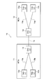
拠点間で通信を行う場合に、現在主に、図8に示すオールインワン型の伝送システム10が適用されている。この伝送システム10では、2拠点のAビル(ビルディング)11及びBビル12の各々に、複数のTRD(Transponder)13a,13bとOXC(optical cross-connect)14とが配備され、Aビル11とBビル12のOXC14間が光ファイバ15で接続されている。更に、伝送システム10は、Aビル11及びBビル12のTRD13a,13bとOXC14とが光ファイバ15a,15bで接続されて構成されている。
オールインワン型の伝送システム10では、Aビル11及びBビル12の全てのTRD13a,13b及びOXC14が同一ベンダVの仕様となっている。
OXC14は、光ファイバ15においてデータ伝送のための光通信路をスイッチングにより自由に設定することができる装置である。このOXC14では、通信の用途や伝送速度毎に形式の異なるデータ伝送経路が存在していた場合でも、データ信号を別の経路に出力することが可能となっている。
TRD13a,13bは、図示せぬユーザのパソコン(パーソナルコンピュータ)、ルータ、スイッチ等の通信機器に接続される中継装置であり、所望の通信機器がTRD13a,13bを介してAビル11及びBビル12間で通信可能となっている。
近年、インターネットを介した動画配信、音声通話、SNS(social networking service)等のマルチメディアを提供するサービスとしてのOTT(Over The Top)が存在する。このOTT主導により伝送システムのオープン化が進んでいる。このため、今までのオールインワン型の伝送システムに代え、後述のディスアグリゲーション型の伝送システムが注目されている。
ディスアグリゲーション型の伝送システムは、オールインワン型の構成要素であるトランスポート機能、WDM(Wavelength Division Multiplexing)機能、スイッチ機能、アクセス機能等の各種の機能を分離して組み合わせ、柔軟且つ迅速に通信サービスを提供する構成となっている。
図9にディスアグリゲーション型の伝送システム20の一構成例を示す。その伝送システム20では、Aビル11及びBビル12の各々に、複数のTRD13a,13bと、MUX(Multiplexer)/DMUX(DeMUX)21と、ROADM(Reconfigurable Optical Add/Drop Multiplexer)22とが配備され、Aビル11とBビル12のROADM22間が光ファイバ15で接続されている。更に、Aビル11及びBビル12において、TRD13a,13bとMUX/DMUX21とが光ファイバ15a,15bで接続され、MUX/DMUX21とROADM22とが光ファイバ15cで接続されている。なお、MUX/DMUX21及びROADM22は、この双方でOXC14に対応する機能を有する。
ディスアグリゲーション型の伝送システム20では、TRD13aがベンダV1の仕様、MUX/DMUX21がベンダV2の仕様、ROADM22がベンダV3の仕様のように、各々が異なるベンダ仕様となっている。
MUX/DMUX21におけるMUXは、複数の信号を多重化して1つの信号として出力し、DMUXは1つの信号を分岐して複数の信号として出力する。ROADM22は、光信号を光のままで分岐又は挿入して多重化処理を行う。このROADM22は、1本の光ファイバに複数の異なる波長の光信号を同時に乗せるWDM(波長分割多重)機能と略同等の機能を有する。
ディスアグリゲーション型の伝送システムの一例として非特許文献1に記載のものがある。また、非特許文献2に、そのディスアグリゲーション型の運用状況の内容例が記載されている。また、オールインワン型の伝送システム10の例として非特許文献3に記載のものがある。また、オールインワン型又はディスアグリゲーション型の伝送システムにおける2拠点間を接続する光ファイバの32波長の波長リソースの例が非特許文献4に記載されている。
"光伝送システム「1FINITY」シリーズのラインアップを大幅拡充",[online],富士通株式会社,2016.3.23,[平成30年4月24日検索],インターネット〈URL:http://pr.fujitsu.com/jp/news/2016/03/23.html#footnote6〉
萩本和男,他2名,"早わかり講座 身近になる光ネットワーク(15)",[online],日経コミュニケーション,2006.6.15,[平成30年4月24日検索],インターネット〈http://tech.nikkeibp.co.jp/it/article/COLUMN/20060607/240199/?rt=nocnt〉
"FUJITSU Network FLASHWAVE 7500S 仕様" ,[online],富士通株式会社,[平成30年4月24日検索],インターネット〈URL: http://www.fujitsu.com/jp/products/network/carrier-router/photonicnetwork/wdm-adm/wdm/flashwave7500s/spec/index.html〉
"Ciena 6500ファミリー",[online],沖電気工業株式会社,[平成30年4月24日検索],インターネット〈URL: https://www.oki.com/jp/optical/product/ciena/6500.html〉
ところで、上述した図8に示したオールインワン型の伝送システム10では、全てのTRD13a,13b及びOXC14が同一ベンダ仕様であるため、Aビル11とBビル12のOXC14間を接続する光ファイバ15に収容可能な波長リソース(例えば10波長)が容易に把握可能である。この場合、波長リソースは例えば10波長と固定されるので、波長リソースを容易に管理できる。
しかし、図9に示したディスアグリゲーション型の伝送システム20では、TRD13a,13bと、MUX/DMUX21と、ROADM22との各々が異なるベンダ仕様である。このため、Aビル11とBビル12のROADM22間を接続する光ファイバ15に収容可能な波長リソースの把握が困難となり、波長リソースを容易に管理できなくなるという問題がある。
本発明は、このような事情に鑑みてなされたものであり、異なるベンダ仕様の各種の伝送機能装置を有する拠点間が光ファイバで接続されて成るディスアグリゲーション型の伝送システムにおいて、その光ファイバに収容可能な波長リソースを容易に把握して管理できる伝送システム及び波長リソース管理方法を提供することを課題とする。
上記課題を解決するための手段として、請求項1に係る発明は、異なるベンダ仕様の各種の伝送機能装置を有する拠点間が光ファイバで接続されて成るディスアグリゲーション型の伝送システムであって、少なくとも、前記伝送機能装置毎の固有情報と、前記伝送機能装置間の接続情報と、前記拠点間の光ファイバにおいて前記伝送機能装置の波長数で定まる収容可能な波長リソースとしての波長数の情報との設備情報をDB(Data Base)情報として記憶するDBと、前記拠点間で光ファイバを介して光信号の伝送を行う際に必要な波長数を依頼するオーダ情報の当該波長数が、前記DB情報に含まれる前記光ファイバに収容可能な波長数よりも多い場合に、前記DB内に前記DB情報を含み記憶されている各伝送機能装置の設備情報に基づき、当該オーダ情報の波長数を前記光ファイバに収容可能とするに必要な前記伝送機能装置毎の波長数を設計する設計部と、前記設計された波長数を該当伝送機能装置に設定する設定部とを備えることを特徴とする伝送システムである。
請求項3に係る発明は、異なるベンダ仕様の各種の伝送機能装置を有する拠点間が光ファイバで接続されて成るディスアグリゲーション型の伝送システムによる波長リソース管理方法であって、前記伝送システムは、少なくとも、前記伝送機能装置毎の固有情報と、前記伝送機能装置間の接続情報と、前記拠点間の光ファイバにおいて前記伝送機能装置の波長数で定まる収容可能な波長リソースとしての波長数の情報との設備情報をDB情報として記憶するDBと、設計部と、設定部とを備え、前記設計部は、前記拠点間で光ファイバを介して光信号の伝送を行う際に必要な波長数を依頼するオーダ情報の当該波長数が、前記DB情報に含まれる前記光ファイバに収容可能な波長数よりも多い場合に、前記DB内に前記DB情報を含み記憶されている各伝送機能装置の設備情報に基づき、当該オーダ情報の波長数を前記光ファイバに収容可能とするに必要な前記伝送機能装置毎の波長数を設計するステップを実行し、前記設定部は、前記設計された波長数を該当伝送機能装置に設定するステップを実行することを特徴とする波長リソース管理方法である。
請求項1の構成及び請求項3の方法によれば、オーダ情報で依頼された光ファイバを介する拠点間の光信号の伝送に必要な波長リソースを、拠点毎の伝送機能装置に自動で設定することができる。このため、ディスアグリゲーション型の伝送システムにおいて、その光ファイバに収容可能な波長リソースを容易に把握して管理することができる。
請求項2に係る発明は、前記設計部は、前記設計による前記伝送機能装置毎の波長数が、前記DB内に記憶された伝送機能装置の全てを用いた場合において前記光ファイバに収容可能な波長数を超えるか否かを判定し、超えた際に伝送機能装置の増設の必要性を表示部に表示する収容可能判定部を備えることを特徴とする請求項1に記載の伝送システムである。
この構成によれば、設計による伝送機能装置の波長数が、DB情報に基づく伝送機能装置で収容可能な波長数を超えた際に伝送機能装置の増設の必要性を表示部に表示することができる。このため、その表示内容をシステム管理者が見て伝送機能装置の増設を行うことができる。
本発明によれば、異なるベンダ仕様の各種の伝送機能装置を有する拠点間が光ファイバで接続されて成るディスアグリゲーション型の伝送システムにおいて、その光ファイバに収容可能な波長リソースを容易に把握して管理できる伝送システム及び波長リソース管理方法を提供することができる。
以下、本発明の実施形態を、図面を参照して説明する。
<実施形態の構成>
図1は、本発明の実施形態に係るディスアグリゲーション型の伝送システムの構成を示すブロック図である。但し、図1に示す伝送システム30において、図9に示した従来の伝送システム20に対応する部分には同一符号を付し、その説明を適宜省略する。
<実施形態の構成>
図1は、本発明の実施形態に係るディスアグリゲーション型の伝送システムの構成を示すブロック図である。但し、図1に示す伝送システム30において、図9に示した従来の伝送システム20に対応する部分には同一符号を付し、その説明を適宜省略する。
図1に示すディスアグリゲーション型の伝送システム30は、通信の拠点であるAビル11及びBビル12の各々に配備されたデータ伝送(データ送受信)に必要な機能を有する各種の伝送機能装置としてのTRD13、MUX/DMUX21及びROADM22を有する。更に、伝送システム30は、本実施形態の特徴要素であるサービスオーダ取得部(取得部ともいう)31と、波長リソース設計部(設計部ともいう)32と、波長リソース設定部(設定部ともいう)33と、設備DB(Data Base)34とを備えて構成されている。但し、TRD13はベンダV1の仕様、MUX/DMUX21はベンダV2の仕様、ROADM22はベンダV3の仕様のように、各々が異なるベンダ仕様となっている。但し、取得部31と、設計部32と、設定部33と、設備DB34とは、各々を個別に装置で構成してもよく、全てを含んで1つの装置で構成してもよい。なお、設備DB34は、請求項記載のDBを構成する。
取得部31は、ユーザ管理等のビジネス面を支援するBSS(Business Support Systems)に基づき構成されている。この取得部31は、ユーザからのサービスオーダ(後述)を受信して取得する。サービスオーダは、例えばAビル11のROADM22とBビル12のROADM22との区間(A-B区間又は拠点間ともいう)に、10GHzの波長の光信号を1つ使用する等の伝送路設定の申込依頼である。
設計部32は、ネットワーク運用を支援するOSS(Operation Support Systems)に基づき構成されている。この設計部32は、A-B区間で光ファイバ15を介して光信号の伝送を行う際に必要な波長数を依頼するオーダ情報の当該波長数が、後述のDB情報D2に含まれる光ファイバ15に収容可能な波長数よりも多い場合に、当該オーダ情報の波長数を光ファイバ15に収容可能な波長数を得るために必要なTRD13、MUX/DMUX21及びROADM22の波長数を設計する。
設計部32は、図2に示すように、情報取得部32aと、差分判定部32bと、計算部32cと、確定部32dと、収容可能判定部32eと、更新部32fと、設定指示部32gと、表示部32hとを備えて構成されている。
情報取得部32aは、取得部31(図1)が受信して取得したサービスオーダ情報(オーダ情報ともいう)D1と、設備DB34に記憶された後述のDB情報D2とを取得する。DB情報D2は、設備DB34に記憶された伝送システム30におけるAビル11及びBビル12の名称等のビル固有情報、フロア情報、TRD13、MUX/DMUX21及びROADM22等の各伝送機能装置の固有情報、各伝送機能装置のポート(後述)の情報、各伝送機能装置の接続情報及び波長数情報等の設備情報を含む。更にDB情報D2は、A-B区間の光ファイバ15に収容可能な波長リソースとしての波長数の情報を含む情報である。
例えば、DB情報D2は、前回のオーダ情報D1に基づき図3に示すAビル11内の設備情報及び図示せぬBビル12内の設備情報が集約されたものであるとする。なお、Aビル11とBビル12との設備情報は同一であると仮定し、このため、Aビル11を代表して説明する。但し、DB情報D2は、現在のDB情報D2以外に各拠点を構成する各種の伝送機能装置の設備情報を記憶している。
図3に示すAビル11の「A」はビル名である。フロア情報は必ずしも必要ではないが、ここでは10階の「10F」であるとする。例えば、TRDの固有情報は12台分の「13a」、「13b」、「13c」、「13d」、…、「13j」であり、MUX/DMUXの固有情報は2台分の「21a」、「21b」であり、ROADMの固有情報は1台分の「22」であるとする。
各TRD13a~13jは、各々、光信号を入出力する1個のポートPを備える。但し、各TRD13a~13jは、図示はしないがユーザ端末機とデータ信号を入出力するポートを、ポートPの反対側に備えているとする。MUX/DMUX21a,21bはTRD側である一方の入出力側に例えば16個のポートPと、ROADM側である他方の入出力側に16個一組のポートP16を備える。ROADM22はMUX/DMUX側に例えば16個一組のポートP16を4つ備え、このポートP16の反対側に光ファイバ15が接続されている。
2つのTRD13a,13bは、一方のMUX/DMUX21aの2つのポートP1,P2に接続され、このMUX/DMUX21aの反対側のポートP16は、ROADM22のポートP16に接続されている。また、10台のTRD13c~13jは、他方のMUX/DMUX21bの10個の第1のポートP1~P10に接続され、このMUX/DMUX21bのポートP16は、ROADM22の第2のポートP16に接続されている。なお、ROADM22の第3及び第4のポートP16は無接続状態である。一方のMUX/DMUX21aのポートP3~P16も無接続状態であり、他方のMUX/DMUX21bのポートP11(図示せず)~P16も無接続状態である。
このような図3に示す設備構成では、各伝送機能装置の波長リソースとして、TRD13a~13jが12波長、MUX/DMUX21a,21bが32波長、ROADM22が32波長なので、この内最も少ないTRD13a~13jの波長数の12波長が光ファイバ15に収容可能な波長リソース(波長数)となる。
この他の設備構成例を図4及び図5に示す。図4に示す設備構成では、TRD13a,13bが2波長、MUX/DMUX21cが24波長、ROADM22が16波長なので、この内最も少ないTRD13a,13bの2波長が光ファイバ15に収容可能な波長リソース(波長数)となる。
図5に示す設備構成では、TRD13a~13xが24波長、MUX/DMUX21cが24波長、ROADM22が16波長なので、この内最も少ないROADM22の16波長が光ファイバ15に収容可能な波長リソース(波長数)となる。
図2に示す差分判定部32bは、オーダ情報D1とDB情報D2とに差分が有るか否かを判定する。但し、DB情報D2が図3に示した設備構成の情報であるとすると、DB情報D2は、ROADM22が32波長、MUX/DMUX21a,21bが32波長、TRD13a~13jが12波長、光ファイバ15に収容可能な波長数の12波長を示す情報となる。
ここで、オーダ情報D1が、A-B区間において、図3に示したAビル11の12台のTRD13a~13jと、Bビル12の図示せぬ12台のTRDとで伝送可能な12波長の波長リソースを使用したい旨のネットワーク設定の依頼情報であるとする。
この場合、オーダ情報D1とDB情報D2とが同じ波長数で差分が0なので、差分判定部32bでは差分無しと判定される。なお、オーダ情報D1の波長数がDB情報D2の波長数よりも小さい場合も差分無しと判定される。
一方、オーダ情報D1が、A-B区間において、16台のTRDで伝送可能な16波長の波長リソースを使用したい旨の依頼情報であるとする。この場合、オーダ情報D1(16波長)とDB情報D2(12波長)との差分が4波長なので、差分判定部32bでは、オーダ情報D1が4波長多い差分有りと判定される。
図2に示す計算部32cは、差分判定部32bでオーダ情報D1が4波長多い差分有りが判定された際に、オーダ情報D1に基づく光ファイバで収容可能な波長数(波長リソース)を得るための各伝送機能装置に必要な波長数を計算する。この場合、A-B区間の光ファイバ15において、16台のTRDで伝送可能な16波長数を得るための各伝送機能装置に必要な波長数が次のように計算される。
計算部32cは、まず、各伝送機能装置の各々の固有情報を取得し、各々の伝送機能装置の数を集計する。次に、各伝送機能装置の接続構成を取得する。次に、各伝送機能装置のポートPを取得し、ポート数を集計する。次に、各伝送機能装置の波長数を集計する。
つまり、計算部32cが、オーダ情報D1に基づく、16台のTRDでA-B区間の光ファイバに収容可能な16波長を得るための各伝送機能装置に必要な波長数を計算する。この場合、まず、計算部32cは、オーダ情報D1に基づく16波長を得るために必要な伝送機能装置としてのTRD、MUX/DMUX、ROADMの各々の数を集計する。次に、計算部32cは、その集計されたTRD、MUX/DMUX、ROADMの接続構成を求める。次に、計算部32cは、その接続構成で使用されたTRD、MUX/DMUX、ROADMのポート数を集計する。
次に、計算部32cは、その集計したポート数に基づき、TRD、MUX/DMUX、ROADMにおいて収容可能な波長数を計算する。これによって、TRDの16波長、MUX/DMUXの32波長、ROADMの32波長が計算される。この計算された各波長数の内、最も少ないTRDの16波長に応じて、A-B区間の光ファイバ15に収容可能な16波長が求められる。
図2に示す確定部32dは、計算部32cで計算された各伝送機能装置の波長数及び拠点間の光ファイバ15の波長数を、波長リソースとして確定する。但し、確定部32dは、差分判定部32bで差分無しと判定された場合は、DB情報D2で示される現在の波長リソースを確定する。
収容可能判定部32eは、確定部32dで確定された各伝送機能装置の波長数及び拠点間の光ファイバ15の波長数が、DB情報D2に含まれる現状の各伝送機能装置及び拠点間の光ファイバ15で収容可能か否かを判定する。
例えば、確定部32dで確定された各伝送機能装置の波長数がDB情報D2に含まれる現状の各伝送機能装置で収容可能であると判定され、この際に、光ファイバ15の収容可能な最大波長数が16波長であると仮定すると、16波長中、DB情報D2に係る12波長が使用中で4波長分が余っている。そこで、既に差分判定部32bで4波長の差分有りと判定されているので、その4波長が光ファイバ15の余った4波長の帯域に収容可能となる。
一方、確定部32dで確定された各波長数が、差分判定部32bで差分無しと判定された際の波長数であれば、収容可能と判定される。
更に、確定部32dで確定された各波長数が、現状の伝送機能装置の波長数及び拠点間の光ファイバ15の収容可能な波長数を超えていれば、収容可能判定部32eは、その超えた波長数の伝送機能装置を増設する内容を表示部32hに表示する。この表示をシステム管理者が見て伝送機能装置の増設を行うことになる。この増設が行われた場合、拠点間の光ファイバ15の収容可能な波長数も増えるので、上記確定された波長数の波長リソースが実現可能となる。
更新部32fは、設備DB34内のDB情報D2を、収容可能判定部32eで収容可能と判定された波長リソースに更新する。例えば、TRDの波長数を16波長、MUX/DMUXの波長数を32波長、ROADMの波長数を32波長、また、A-B区間の光ファイバ15に収容可能な波長数を16波長に更新する。
設定指示部32gは、収容可能判定部32eで収容可能と判定された際に、更新部32fで更新された各伝送機能装置の波長数の設定を指示する設定指示情報D3を設定部33(図1)へ出力する。
図1に示す設定部33は、オーダ情報D1に基づく拠点間の光ファイバ15に収容可能な波長数が定まるように、設定指示情報D3に応じた波長数を該当伝送機能装置に設定する。
<実施形態の動作>
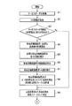
次に、本実施形態に係る伝送システム30におけるAビル11及びBビル12内の各伝送機能装置の波長リソース(波長数)及びA-B区間の光ファイバ15の収容可能な波長リソース(波長数)を設定して管理する際の動作を、図6及び図7のフローチャートを参照して説明する。
次に、本実施形態に係る伝送システム30におけるAビル11及びBビル12内の各伝送機能装置の波長リソース(波長数)及びA-B区間の光ファイバ15の収容可能な波長リソース(波長数)を設定して管理する際の動作を、図6及び図7のフローチャートを参照して説明する。
但し、設備DB34に現在記憶中のDB情報D2が、Aビル11及びBビル12の各々に図3に示すTRD13a~13j、MUX/DMUX21a,21b、ROADM22の各伝送機能装置の固有情報、各伝送機能装置のポート情報、各伝送機能装置の接続情報及び波長数情報を含むと共に、それらの情報を集約した情報であるとする。つまり、TRD13a~13jが12波長、MUX/DMUX21a,21bが32波長、ROADM22が32波長、A-B区間の光ファイバ15に収容可能な12波長である情報を含むとする。
図6のステップS1において、取得部31(図1)が、ユーザからのサービスオーダを受信し、この受信したオーダ情報D1を設計部32(図2)の情報取得部32aへ出力したとする。但し、オーダ情報D1は、A-B区間において、16台のTRDで伝送可能な16波長の波長リソースを使用する内容の情報であるとする。
ステップS2において、情報取得部32aは、設備DB34からDB情報D2を取得し、各情報D1,D2を差分判定部32bへ出力する。
次に、ステップS3において、差分判定部32bは、オーダ情報D1とDB情報D2との差分が有るか否かを判定する。この場合、オーダ情報D1とDB情報D2との双方は上述した内容の情報なので、オーダ情報D1のTRDの波長数の差分が4波長多くなる。このため、差分判定部32bではオーダ情報D1の方が4波長多い差分有り(Yes)と判定される。
この差分有りの判定時に、ステップS4において、計算部32cは、オーダ情報D1に基づくA-B区間の光ファイバ15で収容可能な波長数を得るために、各伝送機能装置に必要な波長数の計算を開始する。
この計算は、まず、ステップS5において、計算部32cが、オーダ情報D1に基づく16波長を得るために必要なTRD、MUX/DMUX、ROADMの各々の数を集計する。
次に、ステップS6において、計算部32cが、上記集計されたTRD、MUX/DMUX、ROADMの接続構成を求める。
次に、ステップS7において、計算部32cが、その接続構成で使用されたTRD、MUX/DMUX、ROADMのポート数を集計する。
次に、ステップS8において、計算部32cが、上記ステップS7で集計したポート数に基づき、A-B区間の光ファイバ15に収容可能な波長数(波長リソース)を得るためのTRD、MUX/DMUX、ROADMに必要な波長数を計算する。これによって、TRDの16波長、MUX/DMUXの32波長、ROADMの32波長が計算され、A-B区間の光ファイバ15に収容可能な16波長が定められる。
この後、ステップS9において、確定部32dは、上記ステップS8で計算されたTRDの16波長、MUX/DMUXの32波長、ROADMの32波長、また、A-B区間の光ファイバ15に収容可能な16波長を、波長リソースとして確定する。
次に、図7に示すステップS10において、収容可能判定部32eは、確定部32dで確定されたTRDの16波長、MUX/DMUXの32波長、ROADMの32波長に基づく、A-B区間の光ファイバ15に収容可能な16波長の各波長数が、DB情報D2に含まれる現状の各伝送機能装置及びA-B区間の光ファイバ15で収容可能か否かを判定する。
この結果、収容可能であると判定(Yes)された場合、ステップS11において、更新部32fは、設備DB34内のDB情報D2を、上記ステップS10で確定された波長リソースに更新する。即ち、TRDの波長数を16波長、MUX/DMUXの波長数を32波長、ROADMの波長数を32波長に更新する。
次に、ステップS12において、設定指示部32gは、上記ステップS11で更新された各設定を指示する設定指示情報D3を設定部33(図1)へ出力する。
次に、ステップS13において、設定部33は、オーダ情報D1に基づく拠点間の光ファイバ15に収容可能な波長数が定まるように、TRD、MUX/DMUX、ROADMに設定指示情報D3に基づく波長数を設定する。この設定により、オーダ情報D1に基づく拠点間の光ファイバ15に収容可能な波長数が定まる。
一方、上記ステップS3の判定において差分判定部32bで後述のように差分無しと判定(No)された場合、ステップS9に進む。即ち、差分無しの判定は、例えば、オーダ情報D1の波長数が、上述したDB情報D2に対応する波長数と同じ、即ち双方の差分が0と判定された場合又は、オーダ情報D1の波長数がDB情報D2の波長数未満とされた場合に、収容可能と判定される。
この場合、ステップS9において、確定部32dは、DB情報D2に基づく、TRD13a~13jの12波長、MUX/DMUX21a,21bの32波長、ROADM22の32波長、A-B区間の光ファイバ15に収容可能な12波長を、波長リソースとして確定する。
また、上記ステップS10において、収容可能判定部32eで収容できないと判定(No)されたとする。これは、上記ステップS9において確定部32dで確定された各波長数が、現状の伝送機能装置の波長数及び拠点間の光ファイバ15の収容可能な波長数を超えている場合である。
この場合、ステップS14において、収容可能判定部32eは、その超えた波長数の伝送機能装置を増設する内容を表示部32hに表示する。この表示をシステム管理者が見て伝送機能装置の増設を行うことになる。この増設が行われた場合、A-B区間の光ファイバ15の収容可能な波長数が、収容可能判定部32eでの判定を満たすように増加されるので、上記ステップS9で確定された波長数の波長リソースを収容可能となる。
<実施形態の効果>
本実施形態に係る伝送システム30による波長リソース管理の効果について説明する。
本実施形態に係る伝送システム30による波長リソース管理の効果について説明する。
(1)伝送システム30は、異なるベンダ仕様の各種の伝送機能装置を有する拠点間が光ファイバ15で接続されて成るディスアグリゲーション型のシステムであり、設備DB34と、設計部32と、設定部33とを備える構成とした。
設備DB34は、少なくとも、伝送機能装置毎の固有情報と、伝送機能装置間の接続情報と、拠点間の光ファイバ15において前記伝送機能装置の波長数で定まる収容可能な波長リソースとしての波長数の情報との設備情報をDB情報D2として記憶する。
設計部32は、拠点間で光ファイバ15を介して光信号の伝送を行う際に必要な波長数を依頼するオーダ情報の当該波長数が、DB情報D2に含まれる光ファイバ15に収容可能な波長数よりも多い場合に、設備DB34内にDB情報D2を含み記憶されている各伝送機能装置の設備情報に基づき、オーダ情報の波長数を光ファイバ15に収容可能とするに必要な伝送機能装置毎の波長数を設計する。
設定部33は、オーダ情報D1に基づく光ファイバ15に収容可能な波長数が定まるように、上記設計された波長数を該当伝送機能装置に設定する。
この構成によれば、オーダ情報D1で依頼された光ファイバ15を介する拠点間の光信号伝送に必要な波長リソースを、拠点毎の伝送機能装置に自動で設定することができる。このため、ディスアグリゲーション型の伝送システムにおいて、その光ファイバ15に収容可能な波長リソースを容易に把握して管理することができる。
(2)設計部32は、上記設計による伝送機能装置毎の波長数が、設備DB34内に記憶された伝送機能装置の全てを用いた場合において光ファイバ15で収容可能な波長数を超えるか否かを判定し、超えた際に伝送機能装置の増設の必要性を表示部32hに表示する収容可能判定部32eを備える構成とした。
この構成によれば、設計による伝送機能装置毎の波長数が、DB情報D2に基づく伝送機能装置で収容可能な波長数を超えた際に伝送機能装置の増設の必要性を表示部32hに表示することができる。このため、その表示内容をシステム管理者が見て伝送機能装置の増設を行うことができる。
その他、具体的な構成について、本発明の主旨を逸脱しない範囲で適宜変更が可能である。
11 Aビル
12 Bビル
13,13a~13x TRD(伝送機能装置)
15 光ファイバ
21,21a~21c MUX/DMUX(伝送機能装置)
22 ROADM(伝送機能装置)
31 サービスオーダ取得部
32 波長リソース設計部(設計部)
33 波長リソース設定部(設定部)
34 設備DB(DB)
32a 情報取得部
32f 差分判定部
32c 計算部
32d 確定部
32e 収容可能判定部
32f 更新部
32g 設定指示部
32h 表示部
D1 サービスオーダ情報(オーダ情報)
D2 DB情報
D3 設定指示情報
12 Bビル
13,13a~13x TRD(伝送機能装置)
15 光ファイバ
21,21a~21c MUX/DMUX(伝送機能装置)
22 ROADM(伝送機能装置)
31 サービスオーダ取得部
32 波長リソース設計部(設計部)
33 波長リソース設定部(設定部)
34 設備DB(DB)
32a 情報取得部
32f 差分判定部
32c 計算部
32d 確定部
32e 収容可能判定部
32f 更新部
32g 設定指示部
32h 表示部
D1 サービスオーダ情報(オーダ情報)
D2 DB情報
D3 設定指示情報
Claims (3)
- 異なるベンダ仕様の各種の伝送機能装置を有する拠点間が光ファイバで接続されて成るディスアグリゲーション型の伝送システムであって、
少なくとも、前記伝送機能装置毎の固有情報と、前記伝送機能装置間の接続情報と、前記拠点間の光ファイバにおいて前記伝送機能装置の波長数で定まる収容可能な波長リソースとしての波長数の情報との設備情報をDB(Data Base)情報として記憶するDBと、
前記拠点間で光ファイバを介して光信号の伝送を行う際に必要な波長数を依頼するオーダ情報の当該波長数が、前記DB情報に含まれる前記光ファイバに収容可能な波長数よりも多い場合に、前記DB内に前記DB情報を含み記憶されている各伝送機能装置の設備情報に基づき、当該オーダ情報の波長数を前記光ファイバに収容可能とするに必要な前記伝送機能装置毎の波長数を設計する設計部と、
前記設計された波長数を該当伝送機能装置に設定する設定部と
を備えることを特徴とする伝送システム。 - 前記設計部は、
前記設計による前記伝送機能装置毎の波長数が、前記DB内に記憶された伝送機能装置の全てを用いた場合において前記光ファイバに収容可能な波長数を超えるか否かを判定し、超えた際に伝送機能装置の増設の必要性を表示部に表示する収容可能判定部を備える
ことを特徴とする請求項1に記載の伝送システム。 - 異なるベンダ仕様の各種の伝送機能装置を有する拠点間が光ファイバで接続されて成るディスアグリゲーション型の伝送システムによる波長リソース管理方法であって、
前記伝送システムは、
少なくとも、前記伝送機能装置毎の固有情報と、前記伝送機能装置間の接続情報と、前記拠点間の光ファイバにおいて前記伝送機能装置の波長数で定まる収容可能な波長リソースとしての波長数の情報との設備情報をDB情報として記憶するDBと、設計部と、設定部とを備え、
前記設計部は、
前記拠点間で光ファイバを介して光信号の伝送を行う際に必要な波長数を依頼するオーダ情報の当該波長数が、前記DB情報に含まれる前記光ファイバに収容可能な波長数よりも多い場合に、前記DB内に前記DB情報を含み記憶されている各伝送機能装置の設備情報に基づき、当該オーダ情報の波長数を前記光ファイバに収容可能とするに必要な前記伝送機能装置毎の波長数を設計するステップを実行し、
前記設定部は、前記設計された波長数を該当伝送機能装置に設定するステップを実行する
ことを特徴とする波長リソース管理方法。
Priority Applications (1)
| Application Number | Priority Date | Filing Date | Title |
|---|---|---|---|
| US17/051,850 US11296790B2 (en) | 2018-05-17 | 2019-05-08 | Transmission system and wavelength resource management method |
Applications Claiming Priority (2)
| Application Number | Priority Date | Filing Date | Title |
|---|---|---|---|
| JP2018-095235 | 2018-05-17 | ||
| JP2018095235A JP6930492B2 (ja) | 2018-05-17 | 2018-05-17 | 伝送システム及び波長リソース管理方法 |
Publications (1)
| Publication Number | Publication Date |
|---|---|
| WO2019220980A1 true WO2019220980A1 (ja) | 2019-11-21 |
Family
ID=68540385
Family Applications (1)
| Application Number | Title | Priority Date | Filing Date |
|---|---|---|---|
| PCT/JP2019/018390 Ceased WO2019220980A1 (ja) | 2018-05-17 | 2019-05-08 | 伝送システム及び波長リソース管理方法 |
Country Status (3)
| Country | Link |
|---|---|
| US (1) | US11296790B2 (ja) |
| JP (1) | JP6930492B2 (ja) |
| WO (1) | WO2019220980A1 (ja) |
Cited By (2)
| Publication number | Priority date | Publication date | Assignee | Title |
|---|---|---|---|---|
| WO2021171354A1 (ja) * | 2020-02-25 | 2021-09-02 | 日本電信電話株式会社 | 伝送装置間接続登録装置、伝送装置間接続登録方法及びプログラム |
| WO2026047821A1 (ja) * | 2024-08-26 | 2026-03-05 | Ntt株式会社 | 光クロスコネクト装置 |
Citations (3)
| Publication number | Priority date | Publication date | Assignee | Title |
|---|---|---|---|---|
| JP2002300206A (ja) * | 2001-03-30 | 2002-10-11 | Nec Corp | ネットワーク設計システム及びネットワーク設計方法、並びにそのプログラム |
| JP2014039208A (ja) * | 2012-08-20 | 2014-02-27 | Fujitsu Ltd | ネットワーク設計装置、ネットワーク設計方法、及びネットワーク設計プログラム |
| WO2015182070A1 (ja) * | 2014-05-27 | 2015-12-03 | 日本電気株式会社 | 光ネットワーク管理装置および光ネットワーク管理方法 |
Family Cites Families (4)
| Publication number | Priority date | Publication date | Assignee | Title |
|---|---|---|---|---|
| JP5391727B2 (ja) * | 2009-02-26 | 2014-01-15 | 富士通株式会社 | 光ネットワーク設計装置および分散補償設計方法 |
| CN110166161B (zh) * | 2015-06-02 | 2020-10-20 | 麻省理工学院 | 在波分复用光通信网络中用于业务减损的自动评估的方法 |
| US10542335B2 (en) * | 2016-02-12 | 2020-01-21 | Nec Corporation | Optical network controller and method of setting optical path |
| EP3300269A1 (en) * | 2016-09-21 | 2018-03-28 | Xieon Networks S.à r.l. | Method, computer program and routing engine for proactive performance-based frequency management |
-
2018
- 2018-05-17 JP JP2018095235A patent/JP6930492B2/ja active Active
-
2019
- 2019-05-08 US US17/051,850 patent/US11296790B2/en active Active
- 2019-05-08 WO PCT/JP2019/018390 patent/WO2019220980A1/ja not_active Ceased
Patent Citations (3)
| Publication number | Priority date | Publication date | Assignee | Title |
|---|---|---|---|---|
| JP2002300206A (ja) * | 2001-03-30 | 2002-10-11 | Nec Corp | ネットワーク設計システム及びネットワーク設計方法、並びにそのプログラム |
| JP2014039208A (ja) * | 2012-08-20 | 2014-02-27 | Fujitsu Ltd | ネットワーク設計装置、ネットワーク設計方法、及びネットワーク設計プログラム |
| WO2015182070A1 (ja) * | 2014-05-27 | 2015-12-03 | 日本電気株式会社 | 光ネットワーク管理装置および光ネットワーク管理方法 |
Non-Patent Citations (2)
| Title |
|---|
| HAYASHI, RIE ET AL.: "Study of OpS Requirements for Future Optical Transport Networks", PROCEEDINGS OF THE 2017 IEICE GENERAL CONFERENCE: COMMUNICATION 2, 7 March 2017 (2017-03-07), pages 354 * |
| SEKIHARA, SHINJI, DISAGGREGATION OF OPTICAL TRANSMISSION SYSTEMS FINALLY ACHIEVED!!, 7 September 2017 (2017-09-07), Retrieved from the Internet <URL:https://www.netone.co.jp/report/column/columnl/20170907.html> * |
Cited By (4)
| Publication number | Priority date | Publication date | Assignee | Title |
|---|---|---|---|---|
| WO2021171354A1 (ja) * | 2020-02-25 | 2021-09-02 | 日本電信電話株式会社 | 伝送装置間接続登録装置、伝送装置間接続登録方法及びプログラム |
| JPWO2021171354A1 (ja) * | 2020-02-25 | 2021-09-02 | ||
| JP7435726B2 (ja) | 2020-02-25 | 2024-02-21 | 日本電信電話株式会社 | 伝送装置間接続登録装置、伝送装置間接続登録方法及びプログラム |
| WO2026047821A1 (ja) * | 2024-08-26 | 2026-03-05 | Ntt株式会社 | 光クロスコネクト装置 |
Also Published As
| Publication number | Publication date |
|---|---|
| US11296790B2 (en) | 2022-04-05 |
| US20210328673A1 (en) | 2021-10-21 |
| JP2019201341A (ja) | 2019-11-21 |
| JP6930492B2 (ja) | 2021-09-01 |
Similar Documents
| Publication | Publication Date | Title |
|---|---|---|
| Amaya et al. | Fully-elastic multi-granular network with space/frequency/time switching using multi-core fibres and programmable optical nodes | |
| US20160269809A1 (en) | Optical network switching device | |
| US20140086576A1 (en) | Determining least-latency paths across a provider network utilizing available capacity | |
| US20140161454A1 (en) | Expandable multicast optical switch | |
| US20220182169A1 (en) | Optical branch insertion device and optical transmission system using optical branch insertion device | |
| US10291971B2 (en) | Optical cross-connect node and optical signal switching method | |
| WO2019220980A1 (ja) | 伝送システム及び波長リソース管理方法 | |
| Garg et al. | Energy efficient flexible hybrid wavelength division multiplexing-time division multiplexing passive optical network with pay as you grow deployment | |
| Tsalamanis et al. | Experimental demonstration of cascaded AWG access network featuring bi-directional transmission and polarization multiplexing | |
| Sahara et al. | Proposal and experimental demonstration of SDM node enabling path assignment to arbitrary wavelengths, cores, and directions | |
| Le et al. | Performance evaluation of large-scale multi-stage hetero-granular optical cross-connects | |
| US7747167B2 (en) | Wavelength service providing apparatus in all-optical network | |
| US6731830B2 (en) | Asymmetric compatible network element | |
| US20240413907A1 (en) | Optical communication apparatus, optical communication system and transmission method | |
| US20050129403A1 (en) | Method and system for communicating optical traffic at a node | |
| US11201687B2 (en) | Optical transmission system and wavelength allocation method | |
| Shiraki et al. | Highly spectrally efficient metro networks that adopt fiber-level granular routing on overlaid line-/ring-shaped virtual topologies | |
| Ishii et al. | Development of hierarchical optical path cross-connect systems employing wavelength/waveband selective switches | |
| Tunesi et al. | Photonic-integrated wavelength selective switch for S+ C+ L applications | |
| JP4724216B2 (ja) | 光通信システム | |
| Woodward et al. | Toward more dynamic optical networking | |
| US20240204903A1 (en) | Optical transmission device, optical transmission system, and optical transmission method | |
| JP3247886B2 (ja) | 光通信網 | |
| Khomchenko et al. | Transmission-aware multiple lightpath reconfiguration in flexgrid optical networks | |
| Kong et al. | Numerical and experimental study of a cascaded microelectromechanical system-based all-optical data center interconnect |
Legal Events
| Date | Code | Title | Description |
|---|---|---|---|
| 121 | Ep: the epo has been informed by wipo that ep was designated in this application |
Ref document number: 19803419 Country of ref document: EP Kind code of ref document: A1 |
|
| NENP | Non-entry into the national phase |
Ref country code: DE |
|
| 122 | Ep: pct application non-entry in european phase |
Ref document number: 19803419 Country of ref document: EP Kind code of ref document: A1 |