WO2019220799A1 - 測色装置 - Google Patents
測色装置 Download PDFInfo
- Publication number
- WO2019220799A1 WO2019220799A1 PCT/JP2019/014786 JP2019014786W WO2019220799A1 WO 2019220799 A1 WO2019220799 A1 WO 2019220799A1 JP 2019014786 W JP2019014786 W JP 2019014786W WO 2019220799 A1 WO2019220799 A1 WO 2019220799A1
- Authority
- WO
- WIPO (PCT)
- Prior art keywords
- opening
- light
- diffuse reflection
- mode
- sample
- Prior art date
- Legal status (The legal status is an assumption and is not a legal conclusion. Google has not performed a legal analysis and makes no representation as to the accuracy of the status listed.)
- Ceased
Links
Images


Classifications
-
- G—PHYSICS
- G01—MEASURING; TESTING
- G01J—MEASUREMENT OF INTENSITY, VELOCITY, SPECTRAL CONTENT, POLARISATION, PHASE OR PULSE CHARACTERISTICS OF INFRARED, VISIBLE OR ULTRAVIOLET LIGHT; COLORIMETRY; RADIATION PYROMETRY
- G01J3/00—Spectrometry; Spectrophotometry; Monochromators; Measuring colours
- G01J3/02—Details
-
- G—PHYSICS
- G01—MEASURING; TESTING
- G01J—MEASUREMENT OF INTENSITY, VELOCITY, SPECTRAL CONTENT, POLARISATION, PHASE OR PULSE CHARACTERISTICS OF INFRARED, VISIBLE OR ULTRAVIOLET LIGHT; COLORIMETRY; RADIATION PYROMETRY
- G01J3/00—Spectrometry; Spectrophotometry; Monochromators; Measuring colours
- G01J3/46—Measurement of colour; Colour measuring devices, e.g. colorimeters
- G01J3/50—Measurement of colour; Colour measuring devices, e.g. colorimeters using electric radiation detectors
-
- G—PHYSICS
- G01—MEASURING; TESTING
- G01N—INVESTIGATING OR ANALYSING MATERIALS BY DETERMINING THEIR CHEMICAL OR PHYSICAL PROPERTIES
- G01N21/00—Investigating or analysing materials by the use of optical means, i.e. using sub-millimetre waves, infrared, visible or ultraviolet light
- G01N21/17—Systems in which incident light is modified in accordance with the properties of the material investigated
- G01N21/55—Specular reflectivity
- G01N21/57—Measuring gloss
Definitions
- the present invention relates to a color measuring device for measuring color.
- the color is perceived when the retina of the eye is stimulated by the light entering the human eye and the human brain reacts to the stimulus.
- the colors recognized by human perception are subjective, but are standardized by the International Commission on Illumination (CIIE), XYZ color system, L * a * b * table. It is possible to quantify the color system (CIE Lab color system) or the L * C * h color system.
- Colors quantified in such a color system are generally measured by a measuring device called a color measuring device (colorimeter).
- a color measuring device color measuring device
- measurement of diffuse illumination conditions special component included, SCI
- specular reflection light specular reflection light
- specular reflection component specular reflection light
- specular reflection component specular reflection light
- no specular reflection light from the sample are included.
- the measurement of the diffuse illumination condition (Special Component Excluded, SCE) is appropriately used depending on, for example, the surface state of the sample, the use application of the color measuring device, and the like. For this reason, for example, Patent Document 1 proposes an apparatus that realizes SCI measurement and SCE measurement.
- the apparatus disclosed in Patent Document 1 includes an integrating sphere having a trap opening and a trap mechanism for opening and closing the trap opening, and the trap mechanism is in a closed state of the trap opening.
- an open / close member whose inner side surface is coated with a white diffuse reflection paint, an arm member fixed at one end to the back surface of the open / close member, and an actuator fixed at the other end of the arm member for making the open state With.
- the apparatus disclosed in Patent Document 1 realizes SCI measurement by closing the open / close member via the arm with the driving force of the actuator, and via the arm with the driving force of the actuator.
- the SCE measurement is realized by opening the opening / closing member.
- the impact may cause the diffuse reflection surface of the opening / closing member to break, There is a risk of chipping.
- the opening / closing member is inclined with respect to the design position, There is a risk of shifting from the position. If the opening / closing member is tilted or deviated from a predetermined position, the amount of light diffusely reflected by the opening / closing member deviates from the predetermined amount of light, and the measurement accuracy deteriorates.
- the present invention has been made in view of the above circumstances, and an object of the present invention is to provide a color measuring device capable of measuring colors with higher accuracy under different diffuse illumination conditions.
- a color measurement device reflecting one aspect of the present invention is a device capable of measuring a sample under first and second diffuse illumination conditions according to the presence or absence of regular reflection light,
- the trap opening and the sample opening formed symmetrically with respect to the normal of the opening surface of the sample opening
- a diffuse reflection member that is fixedly held at a holding position separated from the opening and has an inner surface facing the trap opening as a diffuse reflection surface, and is provided between the trap opening and the diffuse reflection member, and radiates from the trap opening. Switching between a first mode in which the reflected light acts on the diffuse reflection surface of the diffuse reflection member and a second mode in which the light emitted from the trap opening does not act on the diffuse reflection surface of the diffuse reflection member And a structure.
- FIG. 2 is a block diagram showing an electrical configuration of the color measuring device. It is a figure which shows the structure of the integrating sphere in the said colorimetry apparatus, and its peripheral member. It is a graph of the reflectance with respect to a wavelength. It is a graph of the reflectance in SCE measurement with respect to the area ratio of the light absorption member which occupies the range which a light reception system sees. It is a flowchart which shows operation
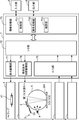
- FIG. 1 is a cross-sectional view illustrating a schematic configuration of a color measuring device according to an embodiment.
- FIG. 2 is a block diagram showing an electrical configuration of the color measuring device.
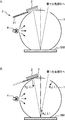
- FIG. 3 is a diagram showing a configuration of an integrating sphere and its peripheral members in the color measuring device.
- FIG. 3A shows the case of the first mode
- FIG. 3B shows the case of the second mode.
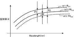
- FIG. 4 is a graph of reflectance with respect to wavelength.
- the horizontal axis in FIG. 4 is the wavelength
- the vertical axis is the reflectance.
- FIG. 5 is a graph of the reflectance in the SCE measurement with respect to the area ratio of the light absorbing member in the range viewed by the light receiving system.
- the horizontal axis in FIG. 5 is the area ratio C of the light absorbing member in the range viewed by the light receiving system
- the vertical axis is the reflectance in SCE measurement.
- the colorimetric apparatus can measure a sample under a first diffuse illumination condition that includes specularly reflected light and can measure the sample under a second diffuse illumination condition that does not include the specularly reflected light in a predetermined geometry.
- the apparatus includes an integrating sphere, a diffuse reflection member, and a mode switching mechanism.
- the integrating sphere is formed in the peripheral wall at a formation position where the first optical axis of the measurement aperture and the second optical axis of the trap aperture are symmetric with respect to the normal line of the aperture surface in the sample aperture as an axis of symmetry.
- a measurement opening, the trap opening, and the sample opening are provided.
- the diffuse reflection member is fixedly held at a holding position apart from the trap opening outside the integrating sphere so as to cover the entire trap opening, and an inner surface facing the trap opening is a diffuse reflection surface.
- This is a member.
- the mode switching mechanism is provided between the trap opening and the diffuse reflection member, and causes the light emitted from the trap opening to act on the diffuse reflection surface of the diffuse reflection member; and the trap This is a mechanism for switching to the second mode in which the light emitted from the aperture for use does not act on the diffuse reflection surface of the diffuse reflection member.
- such a colorimetric device S includes an integrating sphere 1, a diffuse reflection member 2, a mode switching mechanism 3, a light source unit 4, a first beam splitting unit 5, The second spectroscopic unit 6, the control processing unit 7, the input unit 8, the output unit 9, and the housing HS are configured.
- the housing HS houses the integrating sphere 1, the diffuse reflection member 2, the mode switching mechanism 3, the light source unit 4, the first beam splitting unit, the second beam splitting unit 6, the control processing unit 7, the input unit 8 and the output unit 9. It is a box-shaped member.
- the integrating sphere 1 is housed in the housing HS so that the later-described sample opening 111 faces the outside
- the input unit 8 is housed in the housing HS so that an input operation can be performed from the outside
- the output unit 9 is The display surface is accommodated in the housing HS so as to be visible from the outside.
- the integrating sphere 1 obtains the first reflected light (SCI reflected light) from the sample SM by illuminating the sample SM with the diffuse illumination light under the first diffuse illumination condition including the specularly reflected light in a predetermined geometry.
- This is a member for obtaining the second reflected light (SCE reflected light) from the sample SM by illuminating the sample SM with the diffused illumination light under the second diffused illumination condition not including the specularly reflected light.
- the integrating sphere 1 is a hollow sphere member having an inner surface with high diffusion and high reflectance.
- the integrating sphere 1 On the inner surface of the integrating sphere 1, a white diffuse reflection paint such as magnesium oxide (MgO) or barium sulfate (BaSO 2 ) is applied in order to realize the high diffusion and high reflectance.
- the outer surface of the integrating sphere is black to prevent stray light.
- the integrating sphere 1 has a sample opening 111, a measurement opening 112, a trap opening 113, and a light source opening 114 each having a predetermined size (area).
- the light source opening 114 faces the light source opening 114, and the light source opening 114 is formed at a predetermined position of the integrating sphere 1 in order to guide the light (light flux) emitted from the light source section 4 into the integrating sphere 1. Opening (hole) made.
- the sample opening 111 faces the sample SM when the sample SM is measured, and the sample opening 111 diffuses and reflects the light from the light source unit 4 guided into the integrating sphere 1 within the integrating sphere 1. In order to irradiate the sample SM with the diffuse illumination light obtained by doing this, it is an opening (hole) formed at a predetermined location of the integrating sphere 1.
- the first spectroscopic unit 5 faces the measurement aperture 112, and is an opening (hole) formed at a predetermined location of the integrating sphere 1 to guide the reflected light from the sample SM to the first spectroscopic unit 5. is there.
- the trap opening 113 is an opening (hole) formed at a predetermined location of the integrating sphere 1 in order to guide the specularly reflected light of the sample SM to the outside of the integrating sphere 1.
- the first optical axis of the measurement opening 112 and the second optical axis of the trap opening 113 are symmetric with respect to the normal line of the opening surface of the sample opening 111.
- An opening is formed in the peripheral wall of the integrating sphere 1 at the formation position.
- the opening surface of the sample opening 111 generally corresponds to the sample surface of the sample SM when the sample 1 is disposed in the sample opening 111.
- the measurement aperture 112 is in the + 8 ° direction with respect to the normal of the aperture surface (sample surface of the sample SM) in the sample aperture 111.
- the trap opening 113 is formed in a partial region of the peripheral wall of the integrating sphere 1 corresponding to the direction of ⁇ 8 ° with respect to the normal line of the opening surface (sample surface of the sample SM) in the sample opening 111.
- the light source unit 4 is a device that is disposed so as to face the light source opening 114 of the integrating sphere 1 and supplies light (light flux) into the integrating sphere 1.
- the light source unit 4 includes, for example, a lamp 41 and a reflection member 42.
- the lamp 41 is a light emitting element that can emit light having a spectral distribution of a continuous spectrum, such as a xenon lamp.
- the reflecting member 42 is a reflecting umbrella that reflects light emitted from the lamp 41 in a direction opposite to the direction from the lamp 41 toward the light source opening 114 toward the light source opening 114. The amount of light incident on the integrating sphere 1 out of the light emitted from the lamp 41 is increased by the reflecting member 42.
- the reflecting member 42 is a reflecting mirror having a parabolic surface
- the lamp 41 is preferably disposed at a substantially focal position on the parabolic surface.
- the light emitted from the lamp 41 of the light source unit 4 enters the integrating sphere 1 through the light source opening 114 and is diffusely reflected in the integrating sphere 1 to generate white diffuse illumination light.
- the sample SM is illuminated through the opening 111.
- the integrating sphere 1 may include a light source recess formed at a position where the light source opening 114 is formed instead of the light source opening 114, and the lamp 41 of the light source unit 4 may be provided in the recess.
- the diffuse reflection member 2 is a plate-like member having a size (size) that can cover the entire trap opening 113.
- the diffuse reflection member 2 is held at a holding position separated from the trap opening 113 outside the integrating sphere 1 by a predetermined distance so as to cover the entire trap opening 113.
- the diffuse reflection member 2 is fixed and held at the holding position, directly or indirectly via a predetermined holding member, to the housing HS.
- a white diffuse reflection paint such as magnesium oxide (MgO) or barium sulfate (BaSO 2 ) is applied to the inner side surface of the diffuse reflection member 2 facing the trap opening 113.
- MgO magnesium oxide
- BaSO 2 barium sulfate
- the diffuse reflection member 2 may have a flat plate shape, or a curved plate shape in which the inner side surface is recessed with substantially the same curvature as that of the integrating sphere 1.
- the mode switching mechanism 3 is provided between the trap opening 113 and the diffuse reflection member 2, and has a first mode in which the light emitted from the trap opening 113 acts on the diffuse reflection surface of the diffuse reflection member 2, and the trap switching mode 3. This is a mechanism for switching to the second mode in which the light emitted from the opening 113 does not act on the diffuse reflection surface of the diffuse reflection member 2.
- such a mode switching mechanism 3 includes a moving member 31 and an unillustrated moving mechanism 32 that moves the moving member, as shown in FIG.
- the moving member 31 causes the light emitted from the trap opening 113 to act on the diffuse reflection surface of the diffuse reflection member 2.
- the moving member 31 radiates from the trap moving opening 113, which is shown in FIG. This is a plate-like member that is moved by the second movement position (light absorption position) shown in FIG. 3B and the movement mechanism 32 (not shown) that does not cause the reflected light to act on the diffuse reflection surface of the diffuse reflection member 2.
- the inner surface of the moving member 31 that faces the trap opening 113 when moved to the second moving position is a light absorbing surface that absorbs light.
- the light absorbing surface is formed of a light absorbing film (for example, matte black paint) that absorbs light, a light absorbing film formed by plating, or vapor deposition.
- the light absorption surface is formed with a so-called moth-eye structure.
- the light absorption surface is formed by the fine concavo-convex structure, so that the aged deterioration of the light absorption rate can be reduced.
- the moving mechanism 32 (not shown) moves the moving member 31 to the first moving position (FIG. 3A, the retracted position, the standby position) in the first mode, and moves the moving member 31 in the second mode. It is a mechanism for moving to the second movement position (FIG. 3B, light absorption position).
- the moving mechanism 32 (not shown) is, for example, a substantially L-shaped plate member, one end of which is fixed to the moving member 31, the bent portion is rotatably pinned, and the other end is the operation end. It is said.
- the movement mechanism 32 (not shown) having the above-described configuration is configured such that the operation end is configured to be operable from outside the housing HS, or the operation end of the actuator that is controlled by the control processing unit 7 is operated manually. By being connected to the output end, the operating end is swung by the driving force of the actuator, so that the pinned pin rotates and moves around the rotation shaft, thereby being fixed to one end of the moving member 31 is moved to the first movement position in the first mode, and is moved to the second movement position in the second mode.
- the moving member 31 may have a flat plate shape, or may have a curved plate shape in which the inner surface is recessed with substantially the same curvature as that of the integrating sphere 1.
- the unillustrated moving mechanism 32 has a rod having a chopped rack extending between the first and second moving positions and a pinion at the output end fixed to the moving member 31. And an actuator according to the control of the control processing unit 7, and in the first mode, the moving member 31 is guided to the rod and moved to the first movement position by the rack and pinion obtained by meshing the rack and the pinion. In the second mode, the moving member 31 is guided by the rod and moved to the second movement position.
- the first spectroscopic unit 5 is a spectrometer that receives the reflected light from the sample 1 through the measurement aperture 112 of the integrating sphere 1 and spectroscopically measures the reflected light. In spectroscopic measurement, the light intensity of light to be measured is measured for each wavelength at a predetermined wavelength interval. In this embodiment, since it is an 8 ° light receiving d / 8 optical system, the first beam splitting unit 5 is arranged so that its optical axis coincides with the normal of the sample surface of the sample SM in the + 8 ° direction. Established.
- a light guide member such as an optical fiber is faced at a predetermined position of the integrating sphere 1 (not shown), and a part of the diffuse illumination light is guided to the second beam splitting unit 6 by the light guide member. It is configured.
- the second spectroscopic unit 6 receives a part of the diffuse illumination light guided by the light guide member and performs spectroscopic measurement to monitor the diffuse illumination light. It is. By monitoring the diffuse illumination light substantially simultaneously by the second beam splitting unit 6 during the spectroscopic measurement of the first beam splitting unit 5, the light intensity fluctuation of the light source unit 4 during the measurement can be corrected.
- the control processing unit 7 is a circuit that controls the operation of the entire colorimetric device S.
- the control processing unit 7 includes a light emission driving unit 71, an input / output unit (I / O unit) 72, an arithmetic processing unit 73, an illumination condition switching driving unit 74, and an analog unit. / Digital conversion unit (A / D unit) 75.
- the A / D unit 75 is a circuit that converts an analog signal into a digital signal having a predetermined number of bits.
- the A / D unit 75 is connected to the first beam splitting unit 5, the second beam splitting unit 6, and the I / O unit 72, converts an analog signal output from the first beam splitting unit 5 into a digital signal, and converts the analog signal into an I / O unit.
- the analog signal output from the second beam splitting unit 6 is converted into a digital signal and output to the I / O unit 72.
- the I / O unit 72 is an interface circuit, and is connected to the light emission driving unit 71, the illumination condition switching driving unit 74, the A / D unit 75, and the information processing unit 73.
- the I / O unit 72 converts the signal (measurement spectral output signal) output from the A / D unit 75 due to the output signal of the first spectroscopic unit 5 into a format that can be processed by the information processing unit 73 to obtain information.
- a signal (monitor spectral output signal) output to the processing unit 73 and output from the A / D unit 75 due to the output signal of the second spectroscopic unit 6 is converted into a format that can be processed by the information processing unit 73 to obtain information.
- the data is output to the processing unit 73.
- the I / O unit 72 converts the control signal (light emission control signal) output from the information processing unit 73 into a format that can be processed by the light emission drive unit 71 in order to control the light emission operation of the lamp 41 in the light source unit 4. Output to the light emission drive unit 71.
- the I / O unit 72 drives the control signals (first mode control signal and second mode control signal) output from the information processing unit 73 to switch the illumination condition in order to control mode switching in the mode switching mechanism 3.
- the data is converted into a format that can be processed by the unit 74 and output to the illumination condition switching drive unit 74.
- the light emission drive unit 71 supplies drive power to the lamp 41 of the light source unit 4 according to the light emission control signal input from the information processing unit 73 via the I / O unit 72, and uses the light emission control signal as the light emission control signal to the lamp 41 of the light source unit 4. It is a drive circuit which performs the light emission according to.
- the illumination condition switching drive unit 74 supplies driving power to the unillustrated moving mechanism 32 in the mode switching mechanism 3 according to the first or second mode control signal input from the information processing unit 73 via the I / O unit 72.
- the driving circuit causes the moving mechanism 32 (not shown) to perform a mode switching operation according to the first or second mode control signal.
- the information processing unit 73 generates control signals such as a light emission control signal, a first mode control signal, and a second mode control signal in accordance with a control program, for example, in order to control the operation of the entire colorimetric device S, and also reflects reflection characteristics and spectral characteristics.
- a control program for example, in order to control the operation of the entire colorimetric device S, and also reflects reflection characteristics and spectral characteristics.
- characteristics for example, a circuit that obtains reflection characteristics and spectral characteristics by performing arithmetic processing on signals such as the output signal of the first spectroscopic unit 5 and the output signal of the second spectroscopic unit 6 according to a predetermined processing procedure in accordance with a signal processing program. .
- the information processing unit 73 includes a CPU (Central Processing Unit), a storage element (ROM (Read Only Memory), an EEPROM (Electrically Erasable Programmable Read Only Memory), and a RAM (Random Access Memory circuit).
- the CPU is functionally provided with a control unit 731, a colorimetric processing unit 732, and a correction unit 733 by executing a program stored in the storage element.
- the control unit 731 controls the respective units of the color measuring device S according to the functions of the respective units, and controls the entire color measuring device S.
- the colorimetric processing unit 732 measures the color of the sample SM under the first diffuse illumination condition by performing arithmetic processing on the output signal of the first spectroscopic unit 5 and the output signal of the second spectroscopic unit 6 according to a predetermined processing procedure.
- the first diffused illumination is obtained by obtaining first measurement values such as reflection characteristics and spectral characteristics, and calculating the output signal of the first spectroscopic unit 5 and the output signal of the second spectroscopic unit 6 according to a predetermined processing procedure.
- the second measurement values such as reflection characteristics and spectral characteristics when the sample SM is color-measured under the conditions are obtained.
- the correction unit 733 corrects the second measurement value obtained by the colorimetric processing unit 732 with a measurement error due to the return light reflected in the integrating sphere 1 by the light absorption surface of the moving member 31.
- the spectral reflectance R SCI is as shown by the curve ⁇ 1 shown in FIG. Is measured.
- the spectral reflectance FR SCE is represented by a curve ⁇ 2 shown in FIG. Is measured.
- the curve ⁇ 2 shown in FIG. A true value is indicated, and correction by the correction unit 733 is not necessary.
- the correction value ⁇ P is obtained by the correction unit 733, and the spectral reflectance TR SCE of the curve ⁇ 3 shown in FIG. 4 is more accurate from the spectral reflectance FR SCE of the curve ⁇ 2 shown in FIG. Is required.
- the correction unit 733 corrects such a measurement error.
- C ( ⁇ ) is the area ratio of the light absorption surface of the moving member 31 to the inner surface of the integrating sphere as viewed by the first spectroscopic unit 5 through the measurement aperture 112, and the spectral reflectance in the SCE measurement is FR SCE.
- the area ratio C () is obtained by performing SCE measurement with a colorimetric device S on a plurality of samples SMn having a known reflectance and reflected light divergence angle at the manufacturing stage or pre-shipment stage.
- the spectral reflectance FR SCE ( ⁇ ) with respect to ⁇ ) is obtained.
- An example of one predetermined wavelength is shown in FIG. FIG.
- a curve ⁇ of the spectral reflectance FR SCE ( ⁇ ) with respect to the area ratio C ( ⁇ ) is proportional to the area ratio C ( ⁇ ), and the spectral reflection with respect to one area ratio C ( ⁇ ).
- curve ⁇ rate FR SCE the spectral reflectance with respect to the area ratio C from the curve ⁇ of the other ( ⁇ ) ( ⁇ ) FR SCE ( ⁇ ) can be calculated. Then, the spectral reflectance FR SCE ( ⁇ ) with respect to the area ratio C ( ⁇ ) is stored in advance in the arithmetic processing unit 73 at the manufacturing stage, the pre-factory stage, or the like.
- Equation 2 the reflectance R S ( ⁇ ) of the sample SM and the area ratio C ( ⁇ ), which are obtained as follows.
- the spectral reflectance R SCI ( ⁇ ) in the SCI measurement is obtained in advance as described above and stored in the curve ⁇ of the spectral reflectance FR SCE ( ⁇ ) with respect to the area ratio C ( ⁇ ). It can be regarded as a value in the case of C ( ⁇ ) ⁇ 0. Therefore, the correction unit 733 obtains the value in the case of C ( ⁇ ) ⁇ 0 in the curve ⁇ of the spectral reflectance FR SCE ( ⁇ ) with respect to the area ratio C ( ⁇ ), which is obtained and stored in advance as described above.
- the value closest to the spectral reflectance R SCI ( ⁇ ) in this SCI measurement is selected (or the curve ⁇ is calculated), and the spectral ratio for the area ratio C ( ⁇ ) giving this selected value is selected.
- R S ( ⁇ ) corresponding to the curve ⁇ of the reflectance FR SCE ( ⁇ ) is obtained.
- the reflectance R S ( ⁇ ) of the sample SM to be measured from now on is obtained.
- the correcting unit 733 performs spectral reflection in the measurement of the SCE in the curve ⁇ of the spectral reflectance FR SCE ( ⁇ ) with respect to the area ratio C ( ⁇ ) corresponding to the calculated R S ( ⁇ ).
- the area ratio C ( ⁇ ) that gives the rate R SCE ( ⁇ ) is obtained.
- the area ratio C ( ⁇ ) is obtained.
- a correction value ⁇ P ( ⁇ ) corresponding to the value is obtained. Since each of these reflectances R S ( ⁇ ), R W ( ⁇ ), R B ( ⁇ ) and the area ratio C ( ⁇ ) is a function of wavelength, the correction unit 733 corrects the correction value ⁇ P ( ⁇ ). Is also determined for each wavelength ⁇ .
- the correction unit 733 corrects the second measurement value obtained by the colorimetric processing unit 732 with the correction value ⁇ P ( ⁇ ) obtained as described above.
- the input unit 8 is a device for inputting commands (commands), data, and the like from the outside, such as a touch panel and a keyboard.
- the output unit 9 is a device for outputting a command and data input from the input unit 8 and a calculation result of the information processing unit 73, and is an LCD (liquid crystal display), an organic EL display, or the like.
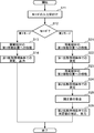
- FIG. 6 is a flowchart showing the operation of the color measuring device.
- control processing unit 7 when a power switch (not shown) is turned on by a user (operator), the control processing unit 7 performs initialization of each necessary unit and executes information processing by executing the control processing program.
- the unit 73 functionally includes a control unit 731, a colorimetric processing unit 732, and a correction unit 733.
- the user measures the color of the sample SM in the first mode of the first diffuse illumination condition or the sample SM in the second mode of the second diffuse illumination condition.
- the mode from the input unit 8.
- the color measuring device S determines whether the accepted mode is the first mode or the second mode by the control unit 731 (S12). As a result of this determination, when the first mode is accepted (first mode), the colorimetric device S sequentially executes each of the processes S13 and S14 and ends the process. On the other hand, if the second mode is accepted as a result of the determination (second mode), the colorimetric device S sequentially executes each of the processes S21 to S26 and ends the process.
- the colorimetric device S outputs a first mode control signal to the illumination condition switching drive unit 74 via the I / O unit 72 by the control unit 731, and causes the mode switching mechanism 3 to open the trap opening 113. Is switched to the first mode in which the light emitted from the diffuse reflection member 2 acts on the diffuse reflection surface of the diffuse reflection member 2. More specifically, according to the first mode control signal, the mode switching mechanism 3 moves the moving member 31 to the first movement position as shown in FIG. 3A by the movement mechanism 32 (not shown).
- the colorimetric device S illuminates the sample SM under the first diffuse illumination condition (SCI condition in the present embodiment) by the colorimetric processing unit 732, and the first and second spectroscopic units 5 and 6 are illuminated.
- the first measurement value (measurement value of SCI measurement in this embodiment) is obtained by performing arithmetic processing on each output signal input from the A / D unit 75 and the I / O unit 72 according to a predetermined processing procedure.
- the obtained first measured value is output from the output unit 9.
- each measurement value of the SCI measurement and the SCE measurement is necessary.
- the control unit 731 outputs the first mode control signal to the illumination condition switching drive unit 74 via the I / O unit 72, and the mode switching mechanism 3 diffuses and reflects the light emitted from the trap opening 113.
- the first mode is switched to act on the diffuse reflection surface of the member 2.
- the colorimetric device S illuminates the sample SM under the first diffuse illumination condition (SCI condition in the present embodiment) by the colorimetric processing unit 732, as in the process S13 described above.
- the first measurement value (this embodiment) is obtained by performing arithmetic processing on each output signal input from the first and second spectroscopic units 5 and 6 via the A / D unit 75 and the I / O unit 72 according to a predetermined processing procedure. Then, a measurement value of SCI measurement) is obtained.
- the color measuring device S outputs a second mode control signal to the illumination condition switching drive unit 74 via the I / O unit 72 by the control unit 731 and causes the mode switching mechanism 3 to trap.
- the mode is switched to the second mode in which the light radiated from the opening 113 does not act on the diffuse reflection surface of the diffuse reflection member 2. More specifically, according to the second mode control signal, the mode switching mechanism 3 moves the moving member 31 to the second moving position by the moving mechanism 32 (not shown) as shown in FIG. 3B.
- the colorimetric device S illuminates the sample SM under the second diffuse illumination condition (SCE condition in the present embodiment) by the colorimetric processing unit 732, and the first and first 2
- the second measurement value (SCE in this embodiment) is obtained by performing arithmetic processing on each output signal input from the spectroscopic units 5 and 6 via the A / D unit 75 and the I / O unit 72 according to a predetermined processing procedure. Measured value of measurement).
- the colorimetric device S obtains a correction value ⁇ P by the correction unit 733. More specifically, the correction unit 733 obtains the spectral reflectance R SCI ( ⁇ ) in the SCI measurement obtained in the processing S22 in the processing S24 for the area ratio C ( ⁇ ) stored in advance. Based on the curve ⁇ of the spectral reflectance FR SCE ( ⁇ ) in the SCE measurement, the reflectance R S ( ⁇ ) of the sample SM is obtained. Next, the correction unit 733 sets the curve S of the spectral reflectance FR SCE ( ⁇ ) corresponding to the area ratio C ( ⁇ ) corresponding to the calculated R S ( ⁇ ) to the calculated SCE.
- the area ratio C ( ⁇ ) is obtained using the spectral reflectance R SCE ( ⁇ ).
- the color measuring device S corrects the second measured value (measured value of SCE measurement in the present embodiment) obtained in the process S24 with the correction value ⁇ P, and the corrected post-correction value.
- the second measurement value is output from the output unit 9.
- the colorimetric device S in this embodiment measures the sample SM under the first diffuse illumination condition and measures the sample SM under the second diffuse illumination condition.
- the colorimetric device S in the present embodiment holds the diffuse reflection member 2 in a fixed manner, and the mode switching mechanism 3 provided between the trap opening 113 and the diffuse reflection member 2 performs the first operation. Since the first mode and the second mode are switched, when the mode switching mechanism 3 abuts on the diffuse reflection member 2, or when the first mode and the second mode are switched, the diffuse reflection member 2 is tilted, There will be no misalignment. For this reason, the colorimetric device S can perform colorimetry with higher accuracy under different diffuse illumination conditions.
- the colorimetric device S includes the correction unit 733, even if the light absorption surface of the moving member 31 does not completely absorb the light and the return light is generated, the color measurement can be performed with higher accuracy in the second mode. .
- the first mode can be realized by moving the moving member 31 having the light absorption surface to the first moving position, and the first mode can be realized by moving the moving member 31 to the second moving position.
- a color measuring device S that can realize two modes can be provided.
- the correction value ⁇ P ( ⁇ ) is obtained for each measurement in the second mode, but a third mode for obtaining the correction value ⁇ P ( ⁇ ) is further provided.
- the correction value ⁇ P ( ⁇ ) obtained in the third mode may be used.
- the third mode is executed for one product to obtain the correction value ⁇ P ( ⁇ ), and this correction value ⁇ P ( ⁇ ) is used for the other products.
- the third mode is executed again for one product in the changed type.
- the mode switching mechanism 3 is configured to include the moving member 31 and the unillustrated moving mechanism 32.
- the mode switching mechanism 3 is not limited to this and has other configurations. Also good.
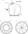
- FIG. 7 is a diagram showing a configuration of an integrating sphere and its peripheral members in the colorimetric device in a modified form.
- FIG. 7A is a cross-sectional view thereof
- FIG. 7B shows the aperture blade in the open state
- FIG. 7C shows the aperture blade in the fully closed state.
- the mode switching mechanism 3a is provided in the trap opening 113, and the aperture blade 10 that opens and closes between an open state and a fully closed state by changing the overlapping state of these blades with a plurality of blades.
- the diaphragm blades 10 are opened in the first mode, and the diaphragm blades 10 are fully closed in the second mode as shown in FIG. 7C.
- an opening / closing mechanism is provided.
- Each of the plurality of blades in the diaphragm blade 10 is a member having an inner surface facing the integrating sphere 1 as a light absorption surface that absorbs light.
- the aperture blade 10 is provided in the trap opening 113 by being fitted into the trap opening 113 as shown in FIG. 7A.
- the diaphragm blade 10 may be provided in contact with the outer surface of the integrating sphere 1 on the periphery of the trap opening 113. According to this, the colorimetric device S can realize the first mode by opening the diaphragm blade 10 having the light absorption surface and can realize the second mode by fully closing the diaphragm blade 10. Can be provided. Since such a colorimetric device S does not require the first and second movement positions in the above-described embodiment, the mode switching mechanism 3a can be provided in a smaller space than the colorimetric device S in the above-described embodiment. it can.
- the color measurement device is a device that can measure a sample under a first diffuse illumination condition including specular reflection light and can measure the sample under a second diffuse illumination condition not including the regular reflection light,
- the measurement opening formed in the peripheral wall at a formation position where the first optical axis of the measurement opening and the second optical axis of the trapping opening are symmetrical with respect to the normal line of the opening surface of the sample opening as a symmetry axis;
- An integrating sphere having a trap opening and the sample opening, and the trap opening that is fixedly held at a holding position spaced from the trap opening outside the integrating sphere so as to cover the entire trap opening.
- a diffuse reflection member having an inner surface facing the diffuse reflection surface, and a light emitted from the trap opening to the diffuse reflection surface of the diffuse reflection member.
- Action Comprising a first mode, a mode switching mechanism for switching a second mode which does not act on the light emitted from the trap opening to the diffusion reflection surface of the diffuse reflection member that.
- the diffuse reflection member is fixedly held, and the mode switching mechanism provided between the trap opening and the diffuse reflection member allows the first mode and the second mode. Therefore, when the mode switching mechanism comes into contact with the diffuse reflection member, or when switching between the first mode and the second mode, the diffuse reflection member is inclined or deviated from a predetermined position. There is no. For this reason, the colorimetric apparatus can perform colorimetry with higher accuracy under different diffuse illumination conditions.
- the mode switching mechanism includes a first movement position where light emitted from the trap opening acts on the diffuse reflection surface of the diffuse reflection member, and the trap opening.
- a moving member that moves to a second movement position that does not act on the diffuse reflection surface of the diffuse reflection member, and moves the movement member to the first movement position in the first mode
- a moving mechanism for moving the moving member to the second moving position in the second mode, and the moving member has an inner surface facing the trap opening when moved to the second moving position, It is a member having a light absorption surface that absorbs light.
- the first mode can be realized by moving the moving member having a light absorption surface to the first moving position (the retracted position, the standby position), and the moving member is moved to the second moving position (light). It is possible to provide a colorimetric device capable of realizing the second mode by moving to the absorption position.
- the mode switching mechanism is provided in the trap opening, and is configured to be opened and closed by a plurality of blades in an open state and a fully closed state, and in the first mode.
- An opening / closing mechanism that opens the diaphragm blades and fully closes the diaphragm blades in the second mode, and each of the plurality of blades in the diaphragm blades faces an integrating sphere.
- the side surface is a member that absorbs light.
- the aperture blade is provided in the trap opening by being fitted into the trap opening.
- a colorimetric device capable of realizing the first mode by opening the aperture blade having a light absorption surface and realizing the second mode by fully closing the aperture blade. Can be provided. Since such a colorimetric device does not require the first and second movement positions described above, the mode switching mechanism can be provided in a smaller space than the colorimetric device described above.
- a first measured value when the sample is measured under the first diffuse illumination condition and a second when the sample is measured under the second diffuse illumination condition A colorimetric processing unit for obtaining a measurement value; and a correction unit for correcting the second measurement value obtained by the colorimetry processing unit with a measurement error caused by return light reflected in the integrating sphere by the light absorption surface.
- Such a colorimetric device further includes the correction unit, even if return light is generated without completely absorbing light by the light absorption surface, color measurement can be performed with higher accuracy in the second mode.
- the light absorbing surface is formed of a coating film of a light absorbing paint.
- the light absorption surface is formed with a moth-eye structure.
- the colorimetric device forms a light absorption surface with a fine concavo-convex structure, it is possible to reduce deterioration over time of the light absorption rate.
- a color measuring device for measuring a color can be provided.
Landscapes
- Physics & Mathematics (AREA)
- Spectroscopy & Molecular Physics (AREA)
- General Physics & Mathematics (AREA)
- Health & Medical Sciences (AREA)
- Life Sciences & Earth Sciences (AREA)
- Chemical & Material Sciences (AREA)
- Analytical Chemistry (AREA)
- Biochemistry (AREA)
- General Health & Medical Sciences (AREA)
- Immunology (AREA)
- Pathology (AREA)
- Spectrometry And Color Measurement (AREA)
- Investigating Or Analysing Materials By Optical Means (AREA)
Abstract
本発明の、正反射光の含非に応じた第1および第2拡散照明条件で試料を測色できる測色装置は、試料用開口における開口面の法線に対し対称に開口形成された測定用開口、トラップ用開口および試料用開口を備える積分球と、トラップ用開口全体を覆うように、積分球外側でトラップ用開口から離間した保持位置に固定的に保持され、トラップ用開口に臨む内側面を拡散反射面とした拡散反射部材と、トラップ用開口から拡散反射部材までの間に設けられ、トラップ用開口から放射された光を拡散反射部材の拡散反射面に作用させる第1モードと、そのように作用させない第2モードとを切り換えるモード切換機構とを備える。
Description
本発明は、色を測定する測色装置に関する。
色は、人の目に入ってきた光に対し、目の網膜が刺激を受け、この刺激に人の脳が反応することによって知覚される。この人の知覚によって認識される色は、主観的なものであるが、国際照明委員会(Commission International de l‘Ecairage,CIE)によって規格化され、XYZ表色系、L*a*b*表色系(CIE Lab表色系)あるいはL*C*h表色系で数値化可能とされている。
このような表色系で数値化される色は、一般に、測色装置(測色計)と呼ばれる計測機器によって測定される。この測色装置では、試料からの正反射光(正反射成分、鏡面反射光、鏡面反射成分)を含む拡散照明条件(Specular Componemt Included、SCI)の測定と、試料からの正反射光を含まない拡散照明条件(Specular Componemt Excluded、SCE)の測定が、例えば、試料の表面状態や測色装置の使用用途等に応じて適宜に使い分けられる。このため、例えば、特許文献1には、SCIの測定とSCEの測定とを実現した装置が提案されている。
この特許文献1に開示された装置は、トラップ用開口部を備えた積分球と、前記トラップ開口部を開閉するためのトラップ機構とを備え、前記トラップ機構は、前記トラップ用開口部を閉状態または開状態とするための、その内側面を白色拡散反射塗料で塗布した開閉部材と、一方端を前記開閉部材の背面に固定されたアーム部材と、前記アーム部材の他方端に固定されたアクチュエータとを備える。この特許文献1に開示された装置は、前記アクチュエータの駆動力で前記アームを介して前記開閉部材を閉状態とすることでSCIの測定を実現し、前記アクチュエータの駆動力で前記アームを介して前記開閉部材を開状態とすることでSCEの測定を実現している。
ところで、SCIの測定の際に、トラップ用開口部を開閉部材で閉状態にするために、積分球本体に開閉部材を当接させると、その衝撃により、開閉部材の拡散反射面が割れたり、欠けたりしてしまう虞がある。このため、閉状態で積分球本体と開閉部材との間に隙間を設けると、この場合では、SCIの測定とSCEの測定とを切り換える際に、設計位置に対して開閉部材が傾いたり、所定位置からずれたりしてしまう虞がある。開閉部材が傾いたり、所定位置からずれたりしてしまうと、開閉部材で拡散反射される光量が所定光量からずれ、測定精度が劣化してしまう。
本発明は、上述の事情に鑑みて為された発明であり、その目的は、互いに異なる各拡散照明条件それぞれでより精度良く測色できる測色装置を提供することである。
上述した目的を実現するために、本発明の一側面を反映した測色装置は、正反射光の含非に応じた第1および第2拡散照明条件で試料を測色できる装置であって、試料用開口における開口面の法線に対し対称に開口形成された測定用開口、トラップ用開口および試料用開口を備える積分球と、トラップ用開口全体を覆うように、積分球の外側におけるトラップ用開口から離間した保持位置に固定的に保持され、トラップ用開口に臨む内側面を拡散反射面とした拡散反射部材と、トラップ用開口から拡散反射部材までの間に設けられ、トラップ用開口から放射された光を拡散反射部材の拡散反射面に作用させる第1モードと、トラップ用開口から放射された光を拡散反射部材の拡散反射面に作用させない第2モードとを切り換えるモード切換機構とを備える。
発明の1または複数の実施形態により与えられる利点および特徴は、以下に与えられる詳細な説明および添付図面から十分に理解される。これら詳細な説明及び添付図面は、例としてのみ与えられるものであり本発明の限定の定義として意図されるものではない。
以下、図面を参照して、本発明の1または複数の実施形態が説明される。しかしながら、発明の範囲は、開示された実施形態に限定されない。なお、各図において同一の符号を付した構成は、同一の構成であることを示し、適宜、その説明を省略する。本明細書において、総称する場合には添え字を省略した参照符号で示し、個別の構成を指す場合には添え字を付した参照符号で示す。
図1は、実施形態における測色装置の概略構成を示す断面図である。図2は、前記測色装置の電気的な構成を示すブロック図である。図3は、前記測色装置における積分球およびその周辺部材の構成を示す図である。図3Aは、第1モードの場合を示し、図3Bは、第2モードの場合を示す。図4は、波長に対する反射率のグラフである。図4の横軸は、波長(wavelength)であり、その縦軸は、反射率である。図5は、受光系が見る範囲に占める光吸収部材の面積割合に対する、SCE測定での反射率のグラフである。図5の横軸は、受光系が見る範囲に占める光吸収部材の面積割合Cであり、その縦軸は、SCE測定での反射率である。
本実施形態における測色装置は、所定のジオメトリにおいて、正反射光を含む第1拡散照明条件で試料を測色でき、前記正反射光を含まない第2拡散照明条件で前記試料を測色できる装置であって、積分球と、拡散反射部材と、モード切換機構とを備える。前記積分球は、試料用開口における開口面の法線を対称軸として測定用開口の第1光軸とトラップ用開口の第2光軸とが対称となる形成位置で周壁に開口形成された前記測定用開口、前記トラップ用開口および前記試料用開口を備える。前記拡散反射部材は、前記トラップ用開口全体を覆うように、前記積分球の外側における前記トラップ用開口から離間した保持位置に固定的に保持され、前記トラップ用開口に臨む内側面を拡散反射面とした部材である。前記モード切換機構は、前記トラップ用開口から前記拡散反射部材までの間に設けられ、前記トラップ用開口から放射された光を前記拡散反射部材の拡散反射面に作用させる第1モードと、前記トラップ用開口から放射された光を前記拡散反射部材の拡散反射面に作用させない第2モードとを切り換える機構である。
このような測色装置Sは、例えば、図1ないし図3に示すように、積分球1と、拡散反射部材2と、モード切換機構3と、光源部4と、第1分光部5と、第2分光部6と、制御処理部7と、入力部8と、出力部9と、筐体HSとを備えて構成されている。
筐体HSは、積分球1、拡散反射部材2、モード切換機構3、光源部4、第1分光部と、第2分光部6、制御処理部7、入力部8および出力部9を収容する箱形の部材である。積分球1は、その後述の試料用開口111が外部に臨むように、筐体HSに収容され、入力部8は、外部から入力操作が可能に筐体HSに収容され、出力部9は、外部から表示面が視認可能に筐体HSに収容される。
積分球1は、所定のジオメトリにおいて、正反射光を含む第1拡散照明条件での拡散照明光で試料SMを照明して試料SMからの第1反射光(SCI反射光)を得るとともに、前記正反射光を含まない第2拡散照明条件での拡散照明光で試料SMを照明して試料SMからの第2反射光(SCE反射光)を得るための部材である。より具体的には、積分球1は、高拡散および高反射率の内面を備えた中空の球体部材である。積分球1の内面には、前記高拡散および高反射率を実現するために、例えば、酸化マグネシウム(MgO)や硫酸バリウム(BaSO2)等の白色拡散反射塗料が塗布されている。積分球の外面は、迷光防止等のために、黒色にされている。そして、積分球1には、試料用開口111と、測定用開口112と、トラップ用開口113と、光源用開口114とがそれぞれ所定の大きさ(面積)で開口(穿孔)されている。
光源用開口114には光源部4が臨まれており、光源用開口114は、光源部4から放射された光(光束)を積分球1内に導くために、積分球1の所定箇所に形成された開口(孔)である。試料用開口111には、試料SMを測定する場合に試料SMが臨まれており、試料用開口111は、積分球1内に導かれた光源部4からの光が積分球1内で拡散反射することによって得られた拡散照明光を試料SMへ照射するために、積分球1の所定箇所に形成された開口(孔)である。
測定用開口112には、第1分光部5が臨まれており、試料SMからの反射光を第1分光部5へ導くために、積分球1の所定箇所に形成された開口(孔)である。トラップ用開口113には、試料SMの正反射光を積分球1の外部へ導くために、積分球1の所定箇所に形成された開口(孔)である。これら測定用開口112およびトラップ用開口113は、試料用開口111における開口面の法線を対称軸として測定用開口112の第1光軸とトラップ用開口113の第2光軸とが対称となる形成位置で積分球1の周壁に開口形成されている。試料用開口111の開口面は、試料用開口部111に試料1が配設された場合に、通常、試料SMの試料面と略一致するものである。前記所定のジオメトリの一例として、8゜受光のd/8光学系の場合では、測定用開口112は、試料用開口111における開口面(試料SMの試料面)の法線に対して+8゜方向に相当する、積分球1における周壁の部分領域に形成される。これに応じて、トラップ用開口113は、試料用開口111における開口面(試料SMの試料面)の法線に対して-8゜方向に相当する、積分球1における周壁の部分領域に形成される。
光源部4は、積分球1の光源用開口114に臨むように配置され、積分球1内に光(光束)を供給する装置である。光源部4は、例えば、ランプ41と、反射部材42とを備えて構成される。ランプ41は、例えばキセノンランプ等の、連続スペクトルの分光分布を持つ光を発光することができる発光素子である。反射部材42は、ランプ41で発光した光のうち、ランプ41から光源用開口114へ向かう方向と反対方向に放射される光を光源用開口114へ向かうように反射する反射傘である。この反射部材42によって、ランプ41で発光した光のうちの積分球1へ入射される光量が増大される。また、より効率よく反射すべく、反射部材42は、放物面を持つ反射鏡であって、ランプ41が前記放物面の略焦点位置に配設されることが好ましい。光源部4のランプ41で発光した光は、光源用開口114を介して積分球1内に入射され、積分球1内で多重に拡散反射することで白色の拡散照明光が生成され、試料用開口111を介して試料SMを照明する。なお、積分球1は、光源用開口114に代え、光源用開口114の形成位置に形成された光源用の凹所を備え、前記凹所に光源部4のランプ41が設けられても良い。
拡散反射部材2は、トラップ用開口113全体を覆うことができるサイズ(大きさ)の板状部材である。拡散反射部材2は、トラップ用開口113全体を覆うように、積分球1の外側におけるトラップ用開口113から所定の距離だけ離間した保持位置に保持されている。例えば、拡散反射部材2は、保持位置で、筐体HSに、直接的にあるいは所定の保持部材を介することで間接的に、固定され保持されている。拡散反射部材2における、トラップ用開口113に臨む内側面は、積分球1の内面と同様に、例えば、酸化マグネシウム(MgO)や硫酸バリウム(BaSO2)等の白色拡散反射塗料が塗布されており、これによって拡散反射面とされている。なお、拡散反射部材2は、平板状であって良く、また、前記内側面が積分球1の曲率と略同一の曲率で凹む湾曲した板状であって良い。
モード切換機構3は、トラップ用開口113から拡散反射部材2までの間に設けられ、トラップ用開口113から放射された光を拡散反射部材2の拡散反射面に作用させる第1モードと、トラップ用開口113から放射された光を拡散反射部材2の拡散反射面に作用させない第2モードとを切り換える機構である。
このようなモード切換機構3は、本実施形態では、図3に示すように、移動部材31と、移動部材を移動させる図略の移動機構32とを備える。
移動部材31は、トラップ用開口113から放射された光を拡散反射部材2の拡散反射面に作用させる、図3Aに示す第1移動位置(待避位置、待機位置)と、トラップ用開口113から放射された光を拡散反射部材2の拡散反射面に作用させない、図3Bに示す第2移動位置(光吸収位置)と前記図略の移動機構32によって移動する板状の部材である。移動部材31における、第2移動位置に移動した場合にトラップ用開口113に臨む内側面は、光を吸収する光吸収面とされている。例えば、前記光吸収面は、光を吸収する光吸収塗料(例えばつや消しの黒色塗料等)やメッキ、蒸着による光吸収膜で形成されている。あるいは、例えば、前記光吸収面は、いわゆるモスアイ構造で形成されている。このモスアイ構造の場合では、微細凹凸構造により構造で光吸収面が形成されるので、光吸収率の経年劣化が低減できる。
前記図略の移動機構32は、前記第1モードの場合に移動部材31を前記第1移動位置(図3A、待避位置、待機位置)に移動させ、前記第2モードの場合に移動部材31を前記第2移動位置(図3B、光吸収位置)に移動させる機構である。
前記図略の移動機構32は、例えば、略L字状の板状部材であり、その一方端が移動部材31に固定され、屈曲部が回動自在にピン留めされ、その他方端が操作端とされる。このような構成の前記図略の移動機構32は、この操作端が筐体HS外から操作可能に構成されることで手動によって、あるいは、この操作端が、制御処理部7の制御に従うアクチュエータの出力端に連結されることでアクチュエータの駆動力によって、前記操作端が揺動されることで、前記ピン留めのピンを回転軸として回転移動し、これによって、その一方端に固定された移動部材31を、前記第1モードでは前記第1移動位置に移動し、前記第2モードでは前記第2移動位置に移動する。本実施形態では、第1および第2移動位置間の切換は、制御処理部7の制御に従った前記アクチュエータによって実行される。なお、この場合では、移動部材31は、平板状であって良く、また、前記内側面が積分球1の曲率と略同一の曲率で凹む湾曲した板状であって良い。
あるいは、例えば、前記図略の移動機構32は、前記第1および第2移動位置間に亘って延び、歯切りしたラックを持つロッドと、移動部材31に固定された、出力端にピニオンを持ち、制御処理部7の制御に従うアクチュエータとを備え、前記ラックと前記ピニオンとを歯合させたラックピニオンによって、前記第1モードでは移動部材31をロッドに案内させて前記第1移動位置に移動させ、前記第2モードでは移動部材31をロッドに案内させて前記第2移動位置に移動させる。
第1分光部5は、試料1からの反射光を積分球1の測定用開口112を介して受光し、この反射光を分光測定する分光計である。分光測定は、測定対象光の光強度を所定の波長間隔で波長ごとに測定するものである。本実施形態では、8゜受光のd/8光学系であることから、第1分光部5は、その光軸が試料SMにおける試料面の法線に対して+8゜方向に一致するように配設される。
そして、積分球1の所定箇所には、例えば光ファイバ等の導光部材が臨まれており(図略)、拡散照明光の一部が前記導光部材によって第2分光部6へ導かれるように構成されている。第2分光部6は、第1分光部5と同様に、前記導光部材によって導かれた前記拡散照明光の一部を受光して分光測定することによって、前記拡散照明光をモニタする分光計である。第1分光部5の分光測定中に第2分光部6によって前記拡散照明光を略同時にモニタすることで、測定中における光源部4の光強度変動を補正することができる。
制御処理部7は、測色装置S全体の動作を司る回路である。制御処理部7は、例えば、図2に示すように、発光駆動部71と、インプット/アウトプット部(I/O部)72と、演算処理部73と、照明条件切替駆動部74と、アナログ/デジタル変換部(A/D部)75とを備えて構成される。
A/D部75は、アナログ信号を所定ビット数のデジタル信号に変換する回路である。A/D部75は、第1分光部5と第2分光部6とI/O部72とに接続され、第1分光部5から出力されるアナログ信号をデジタル信号に変換してI/O部72へ出力し、第2分光部6から出力されるアナログ信号をデジタル信号に変換してI/O部72へ出力する。
I/O部72は、インタフェース回路であり、発光駆動部71と、照明条件切替駆動部74と、A/D部75と、情報処理部73とに接続される。I/O部72は、第1分光部5の出力信号に起因してA/D部75から出力された信号(測定分光出力信号)を情報処理部73で処理可能な形式に変換して情報処理部73へ出力し、第2分光部6の出力信号に起因してA/D部75から出力された信号(モニタ分光出力信号)を情報処理部73で処理可能な形式に変換して情報処理部73へ出力する。I/O部72は、光源部4におけるランプ41の発光動作を制御すべく、情報処理部73から出力された制御信号(発光制御信号)を発光駆動部71で処理可能な形式に変換して発光駆動部71へ出力する。そして、I/O部72は、モード切換機構3におけるモードの切換を制御すべく、情報処理部73から出力された制御信号(第1モード制御信号、第2モード制御信号)を照明条件切替駆動部74で処理可能な形式に変換して照明条件切替駆動部74へ出力する。
発光駆動部71は、I/O部72を介して情報処理部73から入力された発光制御信号に従って光源部4のランプ41に駆動電力を供給し、光源部4のランプ41に発光制御信号に従った発光を行わせる駆動回路である。
照明条件切替駆動部74は、I/O部72を介して情報処理部73から入力された第1または第2モード制御信号に従ってモード切換機構3における前記図略の移動機構32に駆動電力を供給し、前記図略の移動機構32に第1または第2モード制御信号に従ったモード切換の動作を行わせる駆動回路である。
情報処理部73は、測色装置S全体の動作を制御すべく、例えば制御プログラムに従って発光制御信号や第1モード制御信号や第2モード制御信号等の制御信号を生成するとともに、反射特性や分光特性を得るべく、例えば信号処理プログラムに従って第1分光部5の出力信号や第2分光部6の出力信号等の信号を所定の処理手順に従って演算処理し、反射特性や分光特性を得る回路である。情報処理部73は、CPU(Central Processing Unit)、記憶素子(ROM(Read Only Memory)、EEPROM(Electrically Erasable Programmable Read Only Memory)およびRAM(Random Access Memory)等)およびその周辺回路を備えるマイクロコンピュータを備えて構成され、前記記憶素子に記憶されたプログラムの実行によって前記CPUに制御部731、測色処理部732および補正部733を機能的に備える。
制御部731は、測色装置Sの各部を当該各部の機能に応じてそれぞれ制御し、測色装置Sの全体制御を司るものである。
測色処理部732は、第1分光部5の出力信号および第2分光部6の出力信号を所定の処理手順に従って演算処理することによって、前記第1拡散照明条件で試料SMを測色した場合の、反射特性や分光特性等の第1測定値を求め、第1分光部5の出力信号および第2分光部6の出力信号を所定の処理手順に従って演算処理することによって、前記第2拡散照明条件で試料SMを測色した場合の、反射特性や分光特性等の第2測定値を求めるものである。
補正部733は、測色処理部732で求めた第2測定値を、移動部材31における前記光吸収面で積分球1内に反射した戻り光による測定誤差で補正するものである。
第1拡散照明条件、本実施形態では8゜受光のd/8光学系の場合におけるSCIの測定では、第1測定値の一例として、分光反射率RSCIは、図4に示す曲線α1のように測定される。第2拡散照明条件、本実施形態では8゜受光のd/8光学系の場合におけるSCEの測定では、第2測定値の一例として、分光反射率FRSCEは、図4に示す曲線α2のように測定される。ここで、移動部材31における前記光吸収面がトラップ用開口113を介して積分球1から前記光吸収面に放射された拡散反射光を100%吸収する場合では、図4に示す曲線α2は、真値を示し、補正部733による補正は、必要ない。しかしながら、前記光吸収面が100%で吸収できない場合、前記光吸収面が反射して積分球1内に戻る戻り光が生じ、この戻り光によって、図4に示す曲線α2の分光反射率FRSCEには、測定誤差が含まれる。このため、本実施形態では、補正部733によって補正値△Pを求めて、図4に示す曲線α2の分光反射率FRSCEから、より正確な、図4に示す曲線α3の分光反射率TRSCEが求められる。補正部733は、このような測定誤差を補正するものである。
より具体的には、次のように補正値△Pが求められ、補正が行われる。まず、第1分光部5が測定用開口112を介して見る、積分球内面に対する移動部材31の光吸収面の占める面積割合をC(λ)とし、SCEの測定での分光反射率をFRSCE(λ)した場合に、製造段階や工場出荷前段階において、反射率および反射光拡がり角の既知な複数のサンプルSMnを測色装置SでSCEの測定を実施することによって、前記面積割合C(λ)に対する前記分光反射率FRSCE(λ)が求められる。所定の1つの波長について、その一例が図5に示されている。測定用開口112を介して第1分光部5が受光する方向における試料SMの反射率RS(λ)とした場合に、図5には、RS(λ)=1の場合に対応する曲線β1、RS(λ)=0.8の場合に対応する曲線β2、RS(λ)=0.6の場合に対応する曲線β3、RS(λ)=0.4の場合に対応する曲線β4、および、RS(λ)=0.2の場合に対応する曲線β5が図示されているが、前記面積割合C(λ)に対する前記分光反射率FRSCE(λ)は、図5に示すように、複数であっても良く、1個であっても良い。前記面積割合C(λ)に対する前記分光反射率FRSCE(λ)の曲線βは、前記面積割合C(λ)に対して比例関係にあり、1つの前記面積割合C(λ)に対する前記分光反射率FRSCE(λ)の曲線βから他の前記面積割合C(λ)に対する前記分光反射率FRSCE(λ)の曲線βは、演算できる。そして、このような前記面積割合C(λ)に対する前記分光反射率FRSCE(λ)が演算処理部73にこの製造段階や工場出荷前段階等において予め記憶される。
次に、補正値△Pを求める場合には、まず、これから測色する試料SMに対し、測色装置Sを用いてSCIの測定が実行され、分光反射率RSCI(λ)が求められ、次に、この試料SMに対し、測色装置Sを用いてSCEの測定が実行され、分光反射率FRSCE(λ)が求められる。
これによって図4および次式1で表されるSCIの測定とSCEの測定とにおける分光反射率の差分P1(λ)が求められる。
式1;RSCI(λ)-FRSCE(λ)=P1(λ)
式1;RSCI(λ)-FRSCE(λ)=P1(λ)
一方、積分球1の内面の反射率をRW(λ)とし、移動部材31の光吸収面の反射率をRB(λ)とし、光源部4から放射される光量を1に規格化すると、RSCI(λ)は、積分球1で反射された光が試料SMで反射されて測定用開口112を介して第1分光部5で受光されるので、RW(λ)×RS(λ)で表され(RSCI(λ)=RW(λ)×RS(λ))、TRSCE(λ)は、積分球1および移動部材31の光吸収面それぞれで反射された光が試料SMで反射されて測定用開口112を介して第1分光部5で受光されるので、((1-C(λ))×RW(λ)+C(λ)×RB(λ))×RS(λ)で表される(FRSCE(λ)=((1-C(λ))×RW(λ)+C(λ)×RB(λ))×RS(λ))。したがって、P2(λ)は、次式2のように表される。
式2;RW(λ)×RS(λ)-(((1-C(λ))×RW(λ)+C(λ)×RB(λ))×RS(λ))=P2(λ)
式2;RW(λ)×RS(λ)-(((1-C(λ))×RW(λ)+C(λ)×RB(λ))×RS(λ))=P2(λ)
そこで、製造段階や工場出荷前段階において積分球1の内面の反射率RW(λ)および移動部材31の光吸収面の反射率RB(λ)を予め測定して記憶しておくことによって、式2から未知数は、前記試料SMの反射率RS(λ)および前記面積割合C(λ)であり、これらは、次のように、求められる。
まず、SCIの測定での分光反射率RSCI(λ)は、上述のように予め求められ記憶された、前記面積割合C(λ)に対する前記分光反射率FRSCE(λ)の曲線βにおいて、C(λ)→0の場合における値とみなせる。したがって、補正部733は、上述のように予め求められ記憶された、前記面積割合C(λ)に対する前記分光反射率FRSCE(λ)の曲線βにおいて、C(λ)→0の場合における値の中から、このSCIの測定での分光反射率RSCI(λ)に最も近い値を選択し(もしくは曲線βを演算し)、この選択した値を与える前記面積割合C(λ)に対する前記分光反射率FRSCE(λ)の曲線βに対応するRS(λ)を求める。これによって、これから測色する試料SMの反射率RS(λ)が求められる。
次に、補正部733は、この求めたRS(λ)に対応する、前記面積割合C(λ)に対する前記分光反射率FRSCE(λ)の曲線βにおいて、前記SCEの測定での分光反射率RSCE(λ)を与える前記面積割合C(λ)を求める。これによって、前記面積割合C(λ)が求められる。
そして、補正部733は、これら求めた前記試料SMの反射率RS(λ)および前記面積割合C(λ)、ならびに、上述の積分球1の内面の反射率RW(λ)および移動部材31の光吸収面の反射率RB(λ)から、式2によってP2(λ)を求め、△P(λ)=P2(λ)-P1(λ)より、補正値△P(λ)を求める。ここで、所望の反射率RS(λ)を使用することで、例えば戻り光がない状態の分光反射率RSCE(λ)を計算する場合、前記反射率RS(λ)=0とすることで、それに応じた補正値△P(λ)が求められる。これら各反射率RS(λ)、RW(λ)、RB(λ)および前記面積割合C(λ)は、波長の関数であるので、補正部733は、補正値△P(λ)も波長λごとに求める。
そして、第2測定値の測定では、補正部733は、測色処理部732で求めた第2測定値を、上述のように求めた補正値△P(λ)で補正する。
入力部8は、外部からコマンド(命令)やデータ等を入力するための装置であり、例えばタッチパネルやキーボード等である。出力部9は、入力部8から入力されたコマンドやデータおよび情報処理部73の演算結果等を出力するための装置であり、例えばLCD(液晶ディスプレイ)や有機ELディスプレイ等である。
次に、本実施形態における測色装置Sの動作について説明する。図6は、前記測色装置の動作を示すフローチャートである。
このような測色装置Sでは、ユーザ(オペレータ)によって図略の電源スイッチがオンされると、制御処理部7は、必要な各部の初期化を実行し、制御処理プログラムの実行によって、情報処理部73には、制御部731、測色処理部732および補正部733が機能的に構成される。
そして、本実施形態における測色装置Sでは、まず、ユーザ(オペレータ)は、第1拡散照明条件の第1モードで試料SMを測色するか、第2拡散照明条件の第2モードで試料SMを測色するか、を決め、モードを入力部8から入力する。
図6において、入力部8でモードの入力を受け付けると(S11)、測色装置Sは、制御部731によって、この受け付けたモードが第1モードか第2モードかを判定する(S12)。この判定の結果、第1モードを受け付けた場合(第1モード)には、測色装置Sは、処理S13および処理S14の各処理を順次に実行し、処理を終了する。一方、前記判定の結果、第2モードを受け付けた場合(第2モード)には、測色装置Sは、処理S21ないし処理S26の各処理を順次に実行し、処理を終了する。
この処理S13では、測色装置Sは、制御部731によって、第1モード制御信号をI/O部72を介して照明条件切替駆動部74へ出力し、モード切換機構3を、トラップ用開口113から放射された光を拡散反射部材2の拡散反射面に作用させる第1モードに切り換える。より具体的には、第1モード制御信号に従って、モード切換機構3は、移動部材31を、前記図略の移動機構32によって、図3Aに示すように、第1移動位置に移動する。
そして、前記処理S14では、測色装置Sは、測色処理部732によって、第1拡散照明条件(本実施形態ではSCI条件)で試料SMを照明し、第1および第2分光部5、6からA/D部75およびI/O部72を介して入力された各出力信号を所定の処理手順に従って演算処理することによって、第1測定値(本実施形態ではSCIの測定の測定値)を求め、この求めた第1測定値を出力部9から出力する。
一方、補正値を求めるためには、上述したように、SCIの測定およびSCEの測定の各測定値が必要であるので、まず、前記処理S21では、上述の処理S13と同様に、測色装置Sは、制御部731によって、第1モード制御信号をI/O部72を介して照明条件切替駆動部74へ出力し、モード切換機構3を、トラップ用開口113から放射された光を拡散反射部材2の拡散反射面に作用させる第1モードに切り換える。
続いて、前記処理S22では、上述の処理S13と同様に、測色装置Sは、測色処理部732によって、第1拡散照明条件(本実施形態ではSCI条件)で試料SMを照明し、第1および第2分光部5、6からA/D部75およびI/O部72を介して入力された各出力信号を所定の処理手順に従って演算処理することによって、第1測定値(本実施形態ではSCIの測定の測定値)を求める。
続いて、前記処理S23では、測色装置Sは、制御部731によって、第2モード制御信号をI/O部72を介して照明条件切替駆動部74へ出力し、モード切換機構3を、トラップ用開口113から放射された光を拡散反射部材2の拡散反射面に作用させない第2モードに切り換える。より具体的には、第2モード制御信号に従って、モード切換機構3は、移動部材31を、前記図略の移動機構32によって、図3Bに示すように、第2移動位置に移動する。
続いて、前記処理S24では、前記処理S23では、測色装置Sは、測色処理部732によって、第2拡散照明条件(本実施形態ではSCE条件)で試料SMを照明し、第1および第2分光部5、6からA/D部75およびI/O部72を介して入力された各出力信号を所定の処理手順に従って演算処理することによって、第2測定値(本実施形態ではSCEの測定の測定値)を求める。
続いて、前記処理S25では、測色装置Sは、補正部733によって、補正値△Pを求める。より具体的には、補正部733は、前記処理S22で求めたSCIの測定での分光反射率RSCI(λ)を、予め記憶された前記面積割合C(λ)に対する前記処理S24で求めたSCEの測定での分光反射率FRSCE(λ)の曲線βに基づいて、前記試料SMの反射率RS(λ)を求める。次に、補正部733は、この求めたRS(λ)に対応する、前記面積割合C(λ)に対する前記分光反射率FRSCE(λ)の曲線βに、前記求めたSCEの測定での分光反射率RSCE(λ)を用いて、前記面積割合C(λ)を求める。そして、補正部733は、これら前記試料SMの反射率RS(λ)、前記面積割合C(λ)、積分球1の内面の反射率RW(λ)および移動部材31の光吸収面の反射率RB(λ)から、式2によってP2(λ)を求め、△P(λ)=P2(λ)-P1(λ)より、補正値△P(λ)を求める。
そして、前記処理S26では、測色装置Sは、前記処理S24で求めた第2測定値(本実施形態ではSCEの測定の測定値)を補正値△Pで補正し、この補正した補正後の第2測定値を出力部9から出力する。
本実施形態における測色装置Sは、このように第1拡散照明条件で試料SMを測色し、第2拡散照明条件で試料SMを測色する。
以上説明したように、本実施形態における測色装置Sは、拡散反射部材2を固定的に保持し、トラップ用開口113から拡散反射部材2までの間に設けられたモード切換機構3で前記第1モードと前記第2モードとを切り換えるので、モード切換機構3が拡散反射部材2に当接したり、前記第1モードと前記第2モードとを切り換える際に、拡散反射部材2が傾いたり、所定位置からずれたりしてしまうことがない。このため、上記測色装置Sは、互いに異なる各拡散照明条件それぞれでより精度良く測色できる。
上記測色装置Sは、補正部733を備えるので、移動部材31の前記光吸収面で完全に光を吸収できずに、戻り光を生じても、第2モードで、より精度良く測色できる。
本実施形態によれば、光吸収面を持つ移動部材31を前記第1移動位置に移動させることで前記第1モードを実現でき、移動部材31を前記第2移動位置に移動させることで前記第2モードを実現できる測色装置Sが提供できる。
なお、上述の実施形態では、第2モードの測定ごとに補正値△P(λ)が求められたが、補正値△P(λ)を求める第3モードがさらに備えられ、この第3モードで補正値△P(λ)が求められ、第2モードの測定を実施する際に、この第3モードで求められた補正値△P(λ)が用いられても良い。このような場合では、例えば、同種の製品では、1つの製品について第3モードが実行されて補正値△P(λ)が求められ、他の製品について、この補正値△P(λ)が用いられ、製品の種類が変更された場合に、この変更後の種類における1つの製品について再度、第3モードが実行される。
また、上述の実施形態では、モード切換機構3は、移動部材31と、前記図略の移動機構32とを備えて構成されたが、これに限定されるものではなく、他の構成であっても良い。
図7は、変形形態での、前記測色装置における積分球およびその周辺部材の構成を示す図である。図7Aは、その断面図であり、図7Bは、開状態の絞り羽根を示し、図7Cは、全閉状態の絞り羽根を示す。
例えば、図7に示すように、モード切換機構3aは、トラップ用開口113に設けられ、複数の羽根でこれら羽根の重畳状態を変更することで開状態と全閉状態とに開閉する絞り羽根10と、図7Bに示すように、前記第1モードの場合に絞り羽根10を開状態とし、図7Cに示すように、前記第2モードの場合に絞り羽根10を全閉状態とする図略の開閉機構とを備える。絞り羽根10における複数の羽根は、それぞれ、積分球1内に臨む内側面を、光を吸収する光吸収面とした部材である。好ましくは、絞り羽根10は、図7Aに示すように、トラップ用開口113に嵌め込まれることによってトラップ用開口113に設けられる。なお、絞り羽根10は、トラップ用開口113の周縁上で積分球1の外面に当接させて設けられても良い。これによれば、光吸収面を持つ絞り羽根10を開状態とすることで前記第1モードを実現でき、絞り羽根10を全閉状態とすることで前記第2モードを実現できる測色装置Sが提供できる。このような測色装置Sは、上述の実施形態における第1および第2移動位置が不要であるので、上述の実施形態における測色装置Sに較べてモード切換機構3aを省スペースで設けることができる。
本明細書は、上記のように様々な態様の技術を開示しているが、そのうち主な技術を以下に纏める。
一態様にかかる測色装置は、正反射光を含む第1拡散照明条件で試料を測色でき、前記正反射光を含まない第2拡散照明条件で前記試料を測色できる装置であって、試料用開口における開口面の法線を対称軸として測定用開口の第1光軸とトラップ用開口の第2光軸とが対称となる形成位置で周壁に開口形成された前記測定用開口、前記トラップ用開口および前記試料用開口を備える積分球と、前記トラップ用開口全体を覆うように、前記積分球の外側における前記トラップ用開口から離間した保持位置に固定的に保持され、前記トラップ用開口に臨む内側面を拡散反射面とした拡散反射部材と、前記トラップ用開口から前記拡散反射部材までの間に設けられ、前記トラップ用開口から放射された光を前記拡散反射部材の拡散反射面に作用させる第1モードと、前記トラップ用開口から放射された光を前記拡散反射部材の拡散反射面に作用させない第2モードとを切り換えるモード切換機構とを備える。
このような測色装置は、前記拡散反射部材を固定的に保持し、前記トラップ用開口から前記拡散反射部材までの間に設けられた前記モード切換機構で前記第1モードと前記第2モードとを切り換えるので、前記モード切換機構が前記拡散反射部材に当接したり、前記第1モードと前記第2モードとを切り換える際に、前記拡散反射部材が傾いたり、所定位置からずれたりしてしまうことがない。このため、上記測色装置は、互いに異なる各拡散照明条件それぞれでより精度良く測色できる。
他の一態様では、上述の測色装置において、前記モード切換機構は、前記トラップ用開口から放射された光を前記拡散反射部材の拡散反射面に作用させる第1移動位置と、前記トラップ用開口から放射された光を前記拡散反射部材の拡散反射面に作用させない第2移動位置とに移動する移動部材と、前記第1モードの場合に前記移動部材を前記第1移動位置に移動させ、前記第2モードの場合に前記移動部材を前記第2移動位置に移動させる移動機構とを備え、前記移動部材は、前記第2移動位置に移動した場合に、前記トラップ用開口に臨む内側面を、光を吸収する光吸収面とした部材である。
これによれば、光吸収面を持つ前記移動部材を前記第1移動位置(待避位置、待機位置)に移動させることで前記第1モードを実現でき、前記移動部材を前記第2移動位置(光吸収位置)に移動させることで前記第2モードを実現できる測色装置が提供できる。
他の一態様では、上述の測色装置において、前記モード切換機構は、前記トラップ用開口に設けられ、複数の羽根で開状態と全閉状態とに開閉する絞り羽根と、前記第1モードの場合に前記絞り羽根を開状態とし、前記第2モードの場合に前記絞り羽根を全閉状態とする開閉機構とを備え、前記絞り羽根における前記複数の羽根は、それぞれ、積分球内に臨む内側面を、光を吸収する光吸収面とした部材である。好ましくは、上述の測色装置において、前記絞り羽根は、前記トラップ用開口に嵌め込まれることによって前記トラップ用開口に設けられる。
これによれば、光吸収面を持つ前記絞り羽根を開状態とすることで前記第1モードを実現でき、前記絞り羽根を全閉状態とすることで前記第2モードを実現できる測色装置が提供できる。このような測色装置は、上述の第1および第2移動位置が不要であるので、上述の測色装置に較べて前記モード切換機構を省スペースで設けることができる。
他の一態様では、上述の測色装置において、前記第1拡散照明条件で試料を測色した場合の第1測定値と、前記第2拡散照明条件で前記試料を測色した場合の第2測定値とを求める測色処理部と、前記測色処理部で求めた第2測定値を、前記光吸収面で前記積分球内に反射した戻り光による測定誤差で補正する補正部とをさらに備える。
このような測色装置は、前記補正部をさらに備えるので、前記光吸収面で完全に光を吸収できずに、戻り光を生じても、第2モードで、より精度良く測色できる。
他の一態様では、上述の測色装置において、前記光吸収面は、光吸収塗料の塗膜で形成されている。
これによれば、光吸収塗料の塗膜で形成した光吸収面を備える測色装置が提供できる。
他の一態様では、上述の測色装置において、前記光吸収面は、モスアイ構造で形成されている。
これによれば、モスアイ構造で形成した光吸収面を備える測色装置が提供できる。上記測色装置は、微細凹凸構造により光吸収面を形成するので、光吸収率の経年劣化を低減できる。
この出願は、2018年5月15日に出願された日本国特許出願特願2018-93487を基礎とするものであり、その内容は、本願に含まれるものである。
本発明の実施形態が詳細に図示され、かつ、説明されたが、それは単なる図例及び実例であって限定ではない。本発明の範囲は、添付されたクレームの文言によって解釈されるべきである。
本発明を表現するために、上述において図面を参照しながら実施形態を通して本発明を適切且つ十分に説明したが、当業者であれば上述の実施形態を変更および/または改良することは容易に為し得ることであると認識すべきである。したがって、当業者が実施する変更形態または改良形態が、請求の範囲に記載された請求項の権利範囲を離脱するレベルのものでない限り、当該変更形態または当該改良形態は、当該請求項の権利範囲に包括されると解釈される。
本発明によれば、色を測定する測色装置が提供できる。
Claims (6)
- 正反射光を含む第1拡散照明条件で試料を測色でき、前記正反射光を含まない第2拡散照明条件で前記試料を測色できる測色装置であって、
試料用開口における開口面の法線を対称軸として測定用開口の第1光軸とトラップ用開口の第2光軸とが対称となる形成位置で周壁に開口形成された前記測定用開口、前記トラップ用開口および前記試料用開口を備える積分球と、
前記トラップ用開口全体を覆うように、前記積分球の外側における前記トラップ用開口から離間した保持位置に固定的に保持され、前記トラップ用開口に臨む内側面を拡散反射面とした拡散反射部材と、
前記トラップ用開口から前記拡散反射部材までの間に設けられ、前記トラップ用開口から放射された光を前記拡散反射部材の拡散反射面に作用させる第1モードと、前記トラップ用開口から放射された光を前記拡散反射部材の拡散反射面に作用させない第2モードとを切り換えるモード切換機構とを備える、
測色装置。 - 前記モード切換機構は、
前記トラップ用開口から放射された光を前記拡散反射部材の拡散反射面に作用させる第1移動位置と、前記トラップ用開口から放射された光を前記拡散反射部材の拡散反射面に作用させない第2移動位置とに移動する移動部材と、
前記第1モードの場合に前記移動部材を前記第1移動位置に移動させ、前記第2モードの場合に前記移動部材を前記第2移動位置に移動させる移動機構とを備え、
前記移動部材は、前記第2移動位置に移動した場合に、前記トラップ用開口に臨む内側面を、光を吸収する光吸収面とした部材である、
請求項1に記載の測色装置。 - 前記モード切換機構は、
前記トラップ用開口に設けられ、複数の羽根で開状態と全閉状態とに開閉する絞り羽根と、
前記第1モードの場合に前記絞り羽根を開状態とし、前記第2モードの場合に前記絞り羽根を全閉状態とする開閉機構とを備え、
前記絞り羽根における前記複数の羽根は、それぞれ、積分球内に臨む内側面を、光を吸収する光吸収面とした部材である、
請求項1に記載の測色装置。 - 前記第1拡散照明条件で試料を測色した場合の第1測定値と、前記第2拡散照明条件で前記試料を測色した場合の第2測定値とを求める測色処理部と、
前記測色処理部で求めた第2測定値を、前記光吸収面で前記積分球内に反射した戻り光による測定誤差で補正する補正部とをさらに備える、
請求項2または請求項3に記載の測色装置。 - 前記光吸収面は、光吸収塗料の塗膜で形成されている、
請求項2ないし請求項4のいずれか1項に記載の測色装置。 - 前記光吸収面は、モスアイ構造で形成されている、
請求項2ないし請求項4のいずれか1項に記載の測色装置。
Priority Applications (1)
| Application Number | Priority Date | Filing Date | Title |
|---|---|---|---|
| JP2020519504A JPWO2019220799A1 (ja) | 2018-05-15 | 2019-04-03 | 測色装置 |
Applications Claiming Priority (2)
| Application Number | Priority Date | Filing Date | Title |
|---|---|---|---|
| JP2018-093487 | 2018-05-15 | ||
| JP2018093487 | 2018-05-15 |
Publications (1)
| Publication Number | Publication Date |
|---|---|
| WO2019220799A1 true WO2019220799A1 (ja) | 2019-11-21 |
Family
ID=68540180
Family Applications (1)
| Application Number | Title | Priority Date | Filing Date |
|---|---|---|---|
| PCT/JP2019/014786 Ceased WO2019220799A1 (ja) | 2018-05-15 | 2019-04-03 | 測色装置 |
Country Status (2)
| Country | Link |
|---|---|
| JP (1) | JPWO2019220799A1 (ja) |
| WO (1) | WO2019220799A1 (ja) |
Cited By (1)
| Publication number | Priority date | Publication date | Assignee | Title |
|---|---|---|---|---|
| WO2021253577A1 (zh) * | 2020-06-19 | 2021-12-23 | 中国计量大学 | 基于多通道光谱的色差仪及反射率测量方法 |
Citations (5)
| Publication number | Priority date | Publication date | Assignee | Title |
|---|---|---|---|---|
| JPS6363928A (ja) * | 1986-09-04 | 1988-03-22 | Minolta Camera Co Ltd | 微小面測定器 |
| JP2003315154A (ja) * | 2002-04-26 | 2003-11-06 | Minolta Co Ltd | 色彩計測方法および装置 |
| WO2007102173A1 (en) * | 2006-03-09 | 2007-09-13 | Ramesh Datla | Three dimensional shade card generator |
| JP2012242541A (ja) * | 2011-05-18 | 2012-12-10 | Konica Minolta Business Technologies Inc | 画像安定化制御システムおよび画像形成装置 |
| CN103557942A (zh) * | 2013-10-12 | 2014-02-05 | 杭州彩谱科技有限公司 | 双光源兼容sci/sce测试条件的测色仪及实现方法 |
-
2019
- 2019-04-03 WO PCT/JP2019/014786 patent/WO2019220799A1/ja not_active Ceased
- 2019-04-03 JP JP2020519504A patent/JPWO2019220799A1/ja active Pending
Patent Citations (5)
| Publication number | Priority date | Publication date | Assignee | Title |
|---|---|---|---|---|
| JPS6363928A (ja) * | 1986-09-04 | 1988-03-22 | Minolta Camera Co Ltd | 微小面測定器 |
| JP2003315154A (ja) * | 2002-04-26 | 2003-11-06 | Minolta Co Ltd | 色彩計測方法および装置 |
| WO2007102173A1 (en) * | 2006-03-09 | 2007-09-13 | Ramesh Datla | Three dimensional shade card generator |
| JP2012242541A (ja) * | 2011-05-18 | 2012-12-10 | Konica Minolta Business Technologies Inc | 画像安定化制御システムおよび画像形成装置 |
| CN103557942A (zh) * | 2013-10-12 | 2014-02-05 | 杭州彩谱科技有限公司 | 双光源兼容sci/sce测试条件的测色仪及实现方法 |
Cited By (2)
| Publication number | Priority date | Publication date | Assignee | Title |
|---|---|---|---|---|
| WO2021253577A1 (zh) * | 2020-06-19 | 2021-12-23 | 中国计量大学 | 基于多通道光谱的色差仪及反射率测量方法 |
| US12098957B2 (en) | 2020-06-19 | 2024-09-24 | Caipu Technology (Zhejiang) Co., Ltd. | Colorimeter and reflectivity measuring method based on multichannel spectrum |
Also Published As
| Publication number | Publication date |
|---|---|
| JPWO2019220799A1 (ja) | 2021-06-10 |
Similar Documents
| Publication | Publication Date | Title |
|---|---|---|
| US9364071B2 (en) | Systems and methods for measuring spectra of skin and other objects and materials and making predictions based thereon | |
| JP4631080B2 (ja) | 量子効率測定装置および量子効率測定方法 | |
| US9243953B1 (en) | Spectrophotometric colorimeter based on LED light source and method for realizing the same | |
| US20150185081A1 (en) | Spectrometry system, spectroscopic module, and positional deviation detection method | |
| JPH11118603A (ja) | 蛍光試料の分光特性測定装置及びその測定方法 | |
| JPH0650817A (ja) | 試料の光学特性測定装置 | |
| EP3467479B1 (en) | Reflection characteristic measuring device | |
| US5859709A (en) | Optical characteristic measuring apparatus | |
| US20190195783A1 (en) | Optical Unit For Multi-Angle Optical Characteristic Measuring Device, And Multi-Angle Optical Characteristic Measuring Device | |
| JP6421817B2 (ja) | 表面特性測定装置 | |
| WO2019220799A1 (ja) | 測色装置 | |
| JP7600455B2 (ja) | 光学装置 | |
| US9885668B2 (en) | Surface inspection device, surface inspection method, and program | |
| US10989593B2 (en) | Multi-angle colorimeter that suppresses the influence of an inclination of a reference angle on a colorimetric result | |
| JP6765722B2 (ja) | 光学特性測定器 | |
| CN110320669A (zh) | 分光器 | |
| JP2007093273A (ja) | 反射特性測定装置及び反射特性測定方法 | |
| US20230384159A1 (en) | Colorimeter and chromaticity measurement method | |
| JP2007256105A (ja) | 物体の測色方法及び測色装置 | |
| US11231321B2 (en) | Wavelength shift correction system and wavelength shift correction method | |
| KR101034716B1 (ko) | 양자 효율 측정 장치 및 양자 효율 측정 방법 | |
| JP2008309835A (ja) | プロジェクタ及びプロジェクタ画質補正システム | |
| WO2015092994A1 (ja) | カロリー測定装置 | |
| KR102635430B1 (ko) | 측색 장치 및 측색 방법 | |
| JP2022145106A (ja) | 正反射測定装置及び正反射測定装置用試料ホルダ |
Legal Events
| Date | Code | Title | Description |
|---|---|---|---|
| 121 | Ep: the epo has been informed by wipo that ep was designated in this application |
Ref document number: 19804234 Country of ref document: EP Kind code of ref document: A1 |
|
| ENP | Entry into the national phase |
Ref document number: 2020519504 Country of ref document: JP Kind code of ref document: A |
|
| NENP | Non-entry into the national phase |
Ref country code: DE |
|
| 122 | Ep: pct application non-entry in european phase |
Ref document number: 19804234 Country of ref document: EP Kind code of ref document: A1 |