WO2019220535A1 - 画像変換装置および画像変換方法 - Google Patents
画像変換装置および画像変換方法 Download PDFInfo
- Publication number
- WO2019220535A1 WO2019220535A1 PCT/JP2018/018758 JP2018018758W WO2019220535A1 WO 2019220535 A1 WO2019220535 A1 WO 2019220535A1 JP 2018018758 W JP2018018758 W JP 2018018758W WO 2019220535 A1 WO2019220535 A1 WO 2019220535A1
- Authority
- WO
- WIPO (PCT)
- Prior art keywords
- video stream
- unit
- bit rate
- conversion
- rate
- Prior art date
- Legal status (The legal status is an assumption and is not a legal conclusion. Google has not performed a legal analysis and makes no representation as to the accuracy of the status listed.)
- Ceased
Links
Images



Classifications
-
- H—ELECTRICITY
- H04—ELECTRIC COMMUNICATION TECHNIQUE
- H04N—PICTORIAL COMMUNICATION, e.g. TELEVISION
- H04N19/00—Methods or arrangements for coding, decoding, compressing or decompressing digital video signals
- H04N19/10—Methods or arrangements for coding, decoding, compressing or decompressing digital video signals using adaptive coding
- H04N19/134—Methods or arrangements for coding, decoding, compressing or decompressing digital video signals using adaptive coding characterised by the element, parameter or criterion affecting or controlling the adaptive coding
- H04N19/156—Availability of hardware or computational resources, e.g. encoding based on power-saving criteria
-
- H—ELECTRICITY
- H04—ELECTRIC COMMUNICATION TECHNIQUE
- H04N—PICTORIAL COMMUNICATION, e.g. TELEVISION
- H04N19/00—Methods or arrangements for coding, decoding, compressing or decompressing digital video signals
- H04N19/10—Methods or arrangements for coding, decoding, compressing or decompressing digital video signals using adaptive coding
- H04N19/169—Methods or arrangements for coding, decoding, compressing or decompressing digital video signals using adaptive coding characterised by the coding unit, i.e. the structural portion or semantic portion of the video signal being the object or the subject of the adaptive coding
- H04N19/17—Methods or arrangements for coding, decoding, compressing or decompressing digital video signals using adaptive coding characterised by the coding unit, i.e. the structural portion or semantic portion of the video signal being the object or the subject of the adaptive coding the unit being an image region, e.g. an object
- H04N19/172—Methods or arrangements for coding, decoding, compressing or decompressing digital video signals using adaptive coding characterised by the coding unit, i.e. the structural portion or semantic portion of the video signal being the object or the subject of the adaptive coding the unit being an image region, e.g. an object the region being a picture, frame or field
-
- H—ELECTRICITY
- H04—ELECTRIC COMMUNICATION TECHNIQUE
- H04N—PICTORIAL COMMUNICATION, e.g. TELEVISION
- H04N19/00—Methods or arrangements for coding, decoding, compressing or decompressing digital video signals
- H04N19/40—Methods or arrangements for coding, decoding, compressing or decompressing digital video signals using video transcoding, i.e. partial or full decoding of a coded input stream followed by re-encoding of the decoded output stream
-
- H—ELECTRICITY
- H04—ELECTRIC COMMUNICATION TECHNIQUE
- H04N—PICTORIAL COMMUNICATION, e.g. TELEVISION
- H04N21/00—Selective content distribution, e.g. interactive television or video on demand [VOD]
- H04N21/20—Servers specifically adapted for the distribution of content, e.g. VOD servers; Operations thereof
- H04N21/23—Processing of content or additional data; Elementary server operations; Server middleware
- H04N21/234—Processing of video elementary streams, e.g. splicing of video streams or manipulating encoded video stream scene graphs
- H04N21/2343—Processing of video elementary streams, e.g. splicing of video streams or manipulating encoded video stream scene graphs involving reformatting operations of video signals for distribution or compliance with end-user requests or end-user device requirements
Definitions
- the present invention relates to an image conversion apparatus and an image conversion method for converting a bit rate of a video stream and transmitting the converted video stream.
- Patent Document 1 discloses a compression coding apparatus that performs compression coding processing of a frame corresponding to an I picture by thinning out a frame that increases the bit rate of a transmission signal and changing a quality value of image data. Has been.
- Patent Document 1 As the bit rate is converted to a low bit rate so as not to exceed the bit rate due to the bandwidth limitation of the network, the ratio of I picture information to the transmission bandwidth increases. . Therefore, there is a problem that it takes a long time to transmit the video.
- the present invention has been made to solve the above-described problems, and an object thereof is to provide an image conversion apparatus capable of shortening the time required for video transmission.
- An image conversion apparatus includes a video reception unit that receives a video stream, a rate conversion unit that performs bit rate conversion on the video stream received by the video reception unit, and generates a converted video stream, A determination unit that determines whether or not to re-encode the post-video stream; and when the determination unit determines to re-encode the post-conversion video stream, the post-conversion video stream is re-encoded and re-encoded.
- a re-encoding unit that generates a stream and a transmission unit that transmits the re-encoded video stream generated by the re-encoding unit are provided.
- the time required for video transmission can be shortened.
- FIG. 1 is a diagram illustrating a configuration example of an image conversion apparatus according to Embodiment 1.
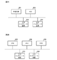
- FIG. 2A and 2B are diagrams illustrating an example of a hardware configuration of the image conversion apparatus according to the first embodiment.
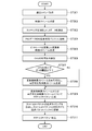
- 3 is a flowchart for explaining an operation of the image conversion apparatus according to the first embodiment.
- 6 is a diagram illustrating a configuration example of an image conversion apparatus according to Embodiment 2.
- FIG. 10 is a flowchart for explaining an operation of the image conversion apparatus according to the second embodiment.
- FIG. 1 is a diagram illustrating a configuration example of an image conversion apparatus 100 according to the first embodiment.
- the image conversion apparatus 100 is connected to a network (not shown in FIG. 1).
- the image conversion apparatus 100 receives a video stream output from an input device such as a camera or a video stream distributed over a network, and converts the bit rate of the received video stream based on a communication command (described later). Then, the video stream after the bit rate conversion is distributed to the network.
- the video stream received by the image conversion apparatus 100 is an encoded video stream.
- the image conversion apparatus 100 includes a command acquisition unit 110, a conversion module control unit 120, and a conversion module unit 130.
- the conversion module unit 130 includes a video reception unit 131, a rate conversion unit 132, a determination unit 133, a re-encoding unit 134, and a transmission control unit 135.
- the determination unit 133 includes a CPU surplus confirmation unit 1331.
- the transmission control unit 135 includes a packet generation unit 1351, a smoothing unit 1352, and a transmission unit 1353.
- the command acquisition unit 110 acquires a communication command transmitted from an external device such as a PC (Personal Computer) to the image conversion apparatus 100.
- an external device such as a PC (Personal Computer)
- the external device transmits a communication command input by the user to the image conversion device 100.
- the communication command for example, an instruction to start or end the conversion module unit 130, information specifying the bit rate of the converted video stream when converting the video stream, and the video stream received by the image conversion apparatus 100 are specified.
- RTP / UDP Real-time Transport Protocol / User Datagram Protocol
- the command acquisition unit 110 outputs the acquired communication command to the conversion module control unit 120.
- the conversion module control unit 120 controls the conversion module unit 130 based on the communication command output from the command acquisition unit 110.
- the conversion module unit 130 receives a video stream under the control of the conversion module control unit 120, converts the bit rate of the received video stream, and converts the bit rate (hereinafter referred to as “converted video stream”). Is transmitted to the network.
- the video receiving unit 131 of the conversion module unit 130 receives a video stream output from an input device or a video stream distributed on a network. At this time, the video reception unit 131 receives the video stream to which the RTP / UDP packet number designated by the conversion module control unit 120 is assigned. In addition, the video reception unit 131 analyzes the RTP header of the received video stream and extracts PES (Packetized Elementary Stream) data. The video reception unit 131 stores the extracted PES data in a video conversion buffer (not shown in FIG. 1). The video reception unit 131 outputs the received video stream to the rate conversion unit 132 of the conversion module unit 130.
- PES Packetized Elementary Stream
- the rate conversion unit 132 converts the bit rate of the video stream received by the video reception unit 131 and generates a converted video stream.
- the rate conversion unit 132 analyzes the PES data stored in the video conversion buffer, and for each of a plurality of frames included in the video stream, each frame is an I picture, a P picture, or a B picture. It is determined whether the picture is one, and an I picture is extracted. In addition, for the P picture or B picture included in the video stream, the rate conversion unit 132 discards the P picture or B picture and then copies the previous picture as it is instead of each discarded picture. A P picture (hereinafter referred to as “P skip frame”) is inserted into the video stream. The reason why the rate conversion unit 132 inserts the P skip frame is to make the converted video stream have a frame rate that can be decoded.
- the rate conversion unit 132 calculates the bit rate of the video stream (hereinafter referred to as “predicted bit rate”) when the video stream is converted into an RTP packet based on the code amount of the extracted I picture and P skip frame. To do. Note that the operation of converting a video stream into an RTP packet is performed by a transmission control unit 135 described later.
- the rate conversion unit 132 determines whether or not the predicted bit rate exceeds the bit rate specified by the conversion module control unit 120 (hereinafter also referred to as “specified bit rate”). When the specified bit rate is exceeded, the I picture is thinned out so that the predicted bit rate is equal to or lower than the specified bit rate.
- the rate conversion unit 132 discards all P pictures or B pictures attached to the thinned I picture. In addition, when the I picture is thinned, the rate conversion unit 132 inserts a P skip frame in the video stream instead of the thinned I picture.
- the rate conversion unit 132 sets a video stream having a specified bit rate or less as a converted video stream. In this manner, the rate conversion unit 132 performs the bit rate conversion process and generates a converted video stream.
- the rate conversion unit 132 outputs the converted video stream to the determination unit 133 of the conversion module unit 130.
- the determination unit 133 determines whether to re-encode the converted video stream output from the rate conversion unit 132. Specifically, the CPU surplus confirmation unit 1331 confirms the load status of the CPU (Central Processing Unit) of the image conversion apparatus 100. Then, the determination unit 133 determines whether or not the CPU load is equal to or less than a threshold (first threshold) based on the CPU load status of the image conversion apparatus 100 confirmed by the CPU surplus confirmation unit 1331. If the load is less than or equal to the first threshold, it is determined that the converted video stream is to be re-encoded. In the first embodiment, “re-encoding” refers to compression-coding the converted video stream so that the video has low image quality.
- the CPU load status confirmed by the CPU surplus confirmation unit 1331 is, for example, the usage rate of the CPU, the usage amount of a memory or a buffer linked to the operation state of the CPU, and the like. 133 determines whether the value based on these information is below a 1st threshold value. Note that the re-encoding unit 134 described later performs re-encoding of the converted video stream.
- the performance of the CPU of the image conversion apparatus 100 is limited. Therefore, if the CPU load is greater than the first threshold, the determination unit 133 determines that it is difficult to perform re-encoding processing in the image conversion apparatus 100 because the CPU load is heavy, and that re-encoding is not performed. To do. On the other hand, if the CPU load is equal to or less than the first threshold, the determination unit 133 determines that re-encoding is performed because the CPU load is light. When determining that the converted video stream is not re-encoded, the determining unit 133 outputs the converted video stream to the transmission control unit 135. If the determination unit 133 determines to re-encode the converted video stream, the determination unit 133 outputs the converted video stream to the re-encoding unit 134.
- the CPU surplus confirmation unit 1331 is provided in the determination unit 133.
- the determination unit 133 only needs to be able to acquire information on the CPU load status and determine whether the CPU load is equal to or less than the first threshold based on the acquired information.
- the re-encoding unit 134 re-encodes the converted video stream output from the determination unit 133, and generates a video stream in which the converted video stream is re-encoded (hereinafter referred to as “re-encoded video stream”). To do.
- the re-encoding unit 134 outputs the re-encoded video stream to the transmission control unit 135.
- the transmission control unit 135 addresses the converted video stream output from the determination unit 133 or the re-encoded video stream output from the re-encoding unit 134, as the transmission destination specified by the conversion module control unit 120.
- RTP / UDP packet including the above information is generated, the transmission timing of the packet is calculated, and the packet is distributed to the network at the calculated timing.
- the packet generation unit 1351 of the transmission control unit 135 generates one or more RTP / UDP packets including information on addresses specified by the conversion module control unit 120 for the converted video stream or the re-encoded video stream. .
- the smoothing unit 1352 of the transmission control unit 135 sends each RTP / UDP packet to the network so that the converted video stream or the re-encoded video stream is smoothed at the bit rate specified by the conversion module control unit 120. Calculate the transmission timing. Smoothing at the bit rate specified by the conversion module control unit 120 means adjusting the transmission interval of RTP / UDP packets on the network so as not to exceed the bit rate. Since the technology for smoothing the video stream is an existing technology, detailed description thereof is omitted.
- the smoothing unit 1352 associates each RTP / UDP packet generated by the packet generation unit 1351 with the calculated transmission timing and stores it in a transmission packet buffer (not shown in FIG. 1).
- the transmission unit 1353 of the transmission control unit 135 sequentially transmits the RTP / UDP packets stored in the transmission packet buffer to the network according to the transmission timing calculated by the smoothing unit 1352.
- FIG. 2A and 2B are diagrams illustrating an example of a hardware configuration of the image conversion apparatus 100 according to Embodiment 1.
- the functions of the conversion module control unit 120 and the conversion module unit 130 are realized by the processing circuit 201.
- the image conversion apparatus 100 includes a processing circuit 201 for performing control to convert a received video stream to a network after converting the received video stream to a bit rate specified by the communication command.
- the processing circuit 201 may be dedicated hardware as shown in FIG. 2A or a CPU (Central Processing Unit) 205 that executes a program stored in the memory 206 as shown in FIG. 2B.
- CPU Central Processing Unit
- the processing circuit 201 may be, for example, a single circuit, a composite circuit, a programmed processor, a parallel programmed processor, an ASIC (Application Specific Integrated Circuit), or an FPGA (Field-Programmable). Gate Array) or a combination of these.
- the functions of the conversion module control unit 120 and the conversion module unit 130 are realized by software, firmware, or a combination of software and firmware. That is, the conversion module control unit 120 and the conversion module unit 130 are realized by a processing circuit such as an HDD (Hard Disk Drive) 202, a CPU 205 that executes a program stored in the memory 206, and a system LSI (Large-Scale Integration). Is done. It can also be said that the programs stored in the HDD 202, the memory 206, and the like cause the computer to execute the procedures and methods of the conversion module control unit 120 and the conversion module unit 130.
- HDD Hard Disk Drive
- LSI Large-Scale Integration
- the memory 206 is, for example, RAM (Random Access Memory), ROM (Read Only Memory), flash memory, EPROM (Erasable Programmable Read Only Memory, etc.) And volatile semiconductor memories, magnetic disks, flexible disks, optical disks, compact disks, mini disks, DVDs (Digital Versatile Discs), and the like.
- RAM Random Access Memory
- ROM Read Only Memory
- flash memory EPROM (Erasable Programmable Read Only Memory, etc.)
- volatile semiconductor memories magnetic disks, flexible disks, optical disks, compact disks, mini disks, DVDs (Digital Versatile Discs), and the like.
- the conversion module control unit 120 and the conversion module unit 130 may be realized by dedicated hardware, and part of the functions may be realized by software or firmware.
- the function of the conversion module control unit 120 is realized by the processing circuit 201 as dedicated hardware, and the function of the conversion module unit 130 is obtained by the processing circuit reading and executing the program stored in the memory 206.
- the HDD 202 is used as the video conversion buffer and the transmission packet buffer. This is merely an example, and the video conversion buffer and the transmission packet buffer may be configured by the memory 206 or the like.
- the image conversion apparatus 100 includes an input interface device 203 and an output interface device 204 that communicate with an external device or a device such as a camera.
- the command acquisition unit 110 includes an input interface device 203.
- FIG. 3 is a flowchart for explaining the operation of the image conversion apparatus 100 according to the first embodiment.
- Command acquisition section 110 acquires a communication command (step ST301).
- the command acquisition unit 110 outputs the acquired communication command to the conversion module control unit 120.
- Video receiving section 131 receives a video stream output from the input device or a video stream distributed on the network (step ST302). In addition, the video reception unit 131 analyzes the RTP header of the video stream received in step ST302, and extracts PES data (step ST303). Then, the video reception unit 131 stores the extracted PES data in the video conversion buffer (step ST304). In addition, the video reception unit 131 outputs the received video stream to the rate conversion unit 132.
- the rate conversion unit 132 performs a bit rate conversion process and generates a converted video stream (step ST305).
- the rate conversion unit 132 outputs the converted video stream to the determination unit 133 of the conversion module unit 130.
- the CPU surplus confirmation unit 1331 confirms the load status of the CPU of the image conversion apparatus 100 (step ST306).
- the determination unit 133 determines whether the CPU load is equal to or less than the first threshold based on the CPU load state of the image conversion apparatus 100 confirmed by the CPU surplus confirmation unit 1331 in step ST307 (step ST307). .
- step ST307 determines to re-encode the converted video stream, and the process proceeds to step ST308. move on. At this time, the determination unit 133 outputs the converted video stream to the re-encoding unit 134.
- step ST307 determines that the CPU load is greater than the first threshold value (in the case of “NO” in step ST307)
- the determination unit 133 determines that the converted video stream is not re-encoded
- the process of ST308 is skipped and proceeds to step ST309.
- the determination unit 133 outputs the converted video stream to the transmission control unit 135.
- the re-encoding unit 134 re-encodes the converted video stream output from the determination unit 133 in Step ST307 to generate a re-encoded video stream (Step ST308).
- the re-encoding unit 134 outputs the re-encoded video stream to the transmission control unit 135.
- the packet generation unit 1351 of the transmission control unit 135 uses the converted video stream output from the determination unit 133 in step ST307 or the re-encoded video stream output from the re-encoding unit 134 in step ST308.
- One or more RTP / UDP packets including the address information designated by the conversion module control unit 120 are generated (step ST309).
- the smoothing unit 1352 of the transmission control unit 135 receives the converted video stream output from the determination unit 133 in step ST307 or the re-encoded video stream output from the re-encoding unit 134 in step ST308. Timing for transmitting each RTP / UDP packet to the network is calculated so as to be smoothed at the bit rate specified by the conversion module control unit 120 (step ST310). The smoothing unit 1352 associates each RTP / UDP packet generated by the packet generation unit 1351 with the calculated transmission timing and stores them in the transmission packet buffer.
- the transmission unit 1353 of the transmission control unit 135 sequentially transmits the RTP / UDP packets stored in the transmission packet buffer to the network according to the transmission timing calculated by the smoothing unit 1352 in step ST310 (step ST311). ).
- determination unit 133 determines the CPU surplus based on the CPU load status of image conversion apparatus 100 confirmed by CPU surplus confirmation unit 1331 (step ST306).
- Step ST307 when there is a surplus, the re-encoding unit 134 re-encodes the converted video stream (see step ST308).
- the re-encoded video stream is a video stream with reduced image quality, and the amount of data is smaller than that of the converted video stream.
- the image conversion apparatus 100 converts the bit rate of the video reception unit 131 that receives the video stream and the video stream received by the video reception unit 131, and
- the determination unit 133 that determines whether to re-encode the post-conversion video stream, or the determination unit 133 determines to re-encode the post-conversion video stream, A re-encoding unit that re-encodes the converted video stream to generate a re-encoded video stream, and a transmission unit 1353 that transmits the re-encoded video stream generated by the re-encoding unit.
- the determination unit 133 performs re-encoding based on the CPU load state of the image conversion apparatus 100 if the load on the CPU is equal to or less than the first threshold value. It was to be determined that. Therefore, the time required for video transmission can be shortened.
- Embodiment 2 the image conversion apparatus 100 determines whether to re-encode the converted video stream based on the load status of the CPU of the image conversion apparatus 100.
- the image conversion apparatus 100a determines whether to re-encode the converted video stream based on the bit rate conversion rate for the received video stream.
- FIG. 4 is a diagram illustrating a configuration example of the image conversion apparatus 100a according to the second embodiment.
- the image conversion apparatus 100a according to the second embodiment is different from the image conversion apparatus 100 according to the first embodiment in that the determination unit 133a includes a rate confirmation unit 1332 instead of the CPU surplus confirmation unit 1331 in the conversion module unit 130a. The point is different.
- the hardware configuration of the image conversion apparatus 100a according to the second embodiment is the same as the hardware configuration of the image conversion apparatus 100 described with reference to FIGS. 2A and 2B in the first embodiment, and thus redundant description is omitted. To do.
- the determination unit 133a determines whether to re-encode the converted video stream output from the rate conversion unit 132. Specifically, the rate confirmation unit 1332 of the determination unit 133a specifies the bit rate of the video stream received by the video reception unit 131 (hereinafter referred to as “first bit rate”) and the conversion module control unit 120. Based on a designated bit rate (hereinafter referred to as “second bit rate”), a conversion rate from the first bit rate to the second bit rate is calculated, and the conversion rate is confirmed. The second bit rate is also the bit rate of the converted video stream. Then, the determination unit 133a determines whether or not the conversion rate is larger than a threshold (second threshold) based on the conversion rate confirmed by the rate confirmation unit 1332.
- first bit rate the bit rate of the video stream received by the video reception unit 131
- second bit rate a designated bit rate from the first bit rate to the second bit rate is calculated, and the conversion rate is confirmed.
- the second bit rate is also the bit rate of the converted video stream. Then,
- the video reception unit 131 outputs the first bit rate to the determination unit 133.
- a value smaller than the first bit rate is always specified for the second bit rate.
- the proportion of the I picture information in the converted video stream occupies the transmission band increases.
- the first bit rate is 10 Mbps and the I picture occupies 20% (2 Mbit) in the video stream.
- the second bit rate is 6 Mbps
- the actually measured value of the bit rate of the converted video stream is approximately 3.7 Mbps (I picture 2 Mbit + P skip frame). Since this does not exceed the second bit rate, the I picture is not thinned out.
- the ratio of the I picture information to the transmission band is 54% because the I picture is 2 Mbit with respect to the actual measured bit rate of the converted video stream of about 3.7 Mbps.
- the rate conversion unit 132 decimates the I picture.
- the conversion rate from the first bit rate to the second bit rate increases as the I picture is thinned out.
- the actual measurement value of the bit rate of the converted video stream is 1.6 Mbps (I picture approximately 1 Mbit + P skip frame), and the ratio of the I picture information to the transmission band is the actual measurement of the bit rate of the converted video stream. Since the I picture is 1 Mbit for the value of about 1.6 Mbps, it is 63%.
- the conversion rate from the first bit rate to the second bit rate is large, it is considered that the ratio of the I picture information in the converted video stream occupies the transmission band increases.
- the determination unit 133a determines to re-encode the converted video stream in order to suppress the ratio of the I picture information to the transmission band. To do. On the other hand, if the conversion rate from the first bit rate to the second bit rate is equal to or less than the second threshold, the ratio of the I picture information in the converted video stream to the transmission band is not so large. It is done. Therefore, the determination unit 133a determines not to re-encode the converted video stream. When determining that the converted video stream is not re-encoded, the determining unit 133a outputs the converted video stream to the transmission control unit 135. When determining that the converted video stream is to be re-encoded, the determining unit 133a outputs the converted video stream to the re-encoding unit 134.
- the rate confirmation unit 1332 is provided in the determination unit 133a.
- the determination unit 133a only needs to be able to acquire information on the conversion rate from the first bit rate to the second bit rate and determine whether the conversion rate is greater than the second threshold.
- FIG. 5 is a flowchart for explaining the operation of the image conversion apparatus 100a according to the second embodiment.
- the specific operations in steps ST501 to ST505 and steps ST508 to ST511 in FIG. 5 are the specific operations in steps ST301 to ST305 and steps ST308 to ST311 in FIG. 3 described in the first embodiment. Since this is the same as the operation, the duplicated explanation is omitted.
- step ST506 and step ST507 of FIG. 5 different from FIG. 3 will be described.
- Rate confirmation section 1332 calculates a conversion rate from the first bit rate to the second bit rate based on the first bit rate and the second bit rate, and confirms the conversion rate (step ST506). Based on the conversion rate confirmed by rate confirmation unit 1332 in step ST506, determination unit 133a determines whether or not the conversion rate is greater than the second threshold (step ST507).
- step ST507 If it is determined in step ST507 that the conversion rate is greater than the second threshold value (in the case of “YES” in step ST507), the determination unit 133a determines to re-encode the converted video stream, and proceeds to step ST508. At this time, the determination unit 133a outputs the converted video stream to the re-encoding unit 134.
- step ST507 when it is determined in step ST507 that the conversion rate is equal to or less than the second threshold (in the case of “NO” in step ST507), the determination unit 133a determines that the converted video stream is not re-encoded, The process of ST508 is skipped and proceeds to step ST509. At this time, the determination unit 133a outputs the converted video stream to the transmission control unit 135.
- the rate conversion unit 132 increases the ratio of the I picture information in the converted video stream to the transmission band. As a result, the time required for transmitting the converted video stream becomes longer. Therefore, based on the conversion rate from the first bit rate to the second bit rate confirmed by the rate confirmation unit 1332, the determination unit 133 a determines that the converted video stream is greater than the second threshold value. Are re-encoded (see step ST507 and step ST508), and the re-encoding unit 134 re-encodes the converted video stream (see step ST508).
- the re-encoded video stream is a video stream with reduced image quality, and the amount of data is smaller than that of the converted video stream.
- the transmission control unit 135 transmits the re-encoded video stream (steps ST509 to ST511), the transmission time can be shortened compared to the case where the converted video stream is transmitted.
- the conversion rate from the first bit rate to the second bit rate is equal to or lower than the second threshold, the converted video stream can be converted without re-encoding the converted video stream. The time required for transmission does not increase. Therefore, the transmission control unit 135 transmits the converted video stream to the network. As a result, it is possible to transmit a video stream with high image quality without reducing the time required for transmission and without reducing the image quality.
- the image conversion apparatus 100a converts the bit rate of the video reception unit 131 that receives the video stream and the video stream received by the video reception unit 131, and performs the conversion.
- the rate conversion unit 132 that generates the post-video stream
- the determination unit 133 that determines whether to re-encode the post-conversion video stream, or the determination unit 133 determines to re-encode the post-conversion video stream
- a re-encoding unit 134 that re-encodes the converted video stream to generate a re-encoded video stream
- a transmission unit 1353 that transmits the re-encoded video stream generated by the re-encoding unit 134.
- the determination unit 133 configures the first bit rate that is the bit rate of the video stream and the first bit rate that is the bit rate of the converted video stream. Based on the bit rate, the conversion rate from the first bit rate to the second bit rate is greater than or equal to the second threshold value, and to determine the re-encoding. Therefore, as in Embodiment 1, the time required for video transmission can be shortened.
- the image conversion apparatuses 100 and 100a include the command acquisition unit 110 and the conversion module control unit 120, as shown in FIGS.
- the image conversion apparatuses 100 and 100a may not include the command acquisition unit 110 and the conversion module control unit 120.
- the image conversion devices 100 and 100a store communication commands in advance, and the conversion module units 130 and 130a operate based on the stored communication commands and control signals transmitted from the external device. May be.
- the invention of the present application can be freely combined with each embodiment, modified with any component in each embodiment, or omitted with any component in each embodiment. .
- the image conversion apparatus Since the image conversion apparatus according to the present invention is configured to be able to reduce the time required for video transmission, it is applied to an image conversion apparatus that converts the bit rate of the video stream and transmits the converted video stream. can do.
Landscapes
- Engineering & Computer Science (AREA)
- Multimedia (AREA)
- Signal Processing (AREA)
- Computing Systems (AREA)
- Theoretical Computer Science (AREA)
- Compression Or Coding Systems Of Tv Signals (AREA)
- Two-Way Televisions, Distribution Of Moving Picture Or The Like (AREA)
Abstract
映像ストリームを受信する映像受信部(131)と、映像受信部(131)が受信した映像ストリームに対し、ビットレートの変換を行い、変換後映像ストリームを生成するレート変換部(132)と、変換後映像ストリームを再符号化するか否かを判断する判断部(133)と、判断部(133)が変換後映像ストリームを再符号化すると判断した場合に、当該変換後映像ストリームを再符号化して再符号化後映像ストリームを生成する再符号化部(134)と、再符号化部(134)が生成した再符号化後映像ストリームを伝送する伝送部(1353)とを備えた。
Description
この発明は、映像ストリームのビットレートを変換し、変換後の映像ストリームを伝送する画像変換装置および画像変換方法に関する。
従来、映像ストリームを、ネットワークを介して伝送するシステムにおいて、パケットロスを防ぐため、伝送信号のビットレートのピーク値をネットワークの帯域制限の範囲内に収めるようにする技術が知られている。
例えば、特許文献1には、伝送信号のビットレートを増大させるフレームを間引いて、画像データの品質値を変化させて、Iピクチャに相当するフレームの圧縮符号化処理を行う圧縮符号化装置が開示されている。
例えば、特許文献1には、伝送信号のビットレートを増大させるフレームを間引いて、画像データの品質値を変化させて、Iピクチャに相当するフレームの圧縮符号化処理を行う圧縮符号化装置が開示されている。
特許文献1に開示されているような従来技術では、ネットワークの帯域制限によるビットレートを超過しない値となるよう、低ビットレートへと変換するにつれ、Iピクチャの情報が伝送帯域を占める割合が増える。そのため、映像を伝送するために長い時間を要するという課題があった。
この発明は上記のような課題を解決するためになされたもので、映像の伝送に要する時間を短くすることができる画像変換装置を提供することを目的とする。
この発明に係る画像変換装置は、映像ストリームを受信する映像受信部と、映像受信部が受信した映像ストリームに対し、ビットレートの変換を行い、変換後映像ストリームを生成するレート変換部と、変換後映像ストリームを再符号化するか否かを判断する判断部と、判断部が変換後映像ストリームを再符号化すると判断した場合に、当該変換後映像ストリームを再符号化して再符号化後映像ストリームを生成する再符号化部と、再符号化部が生成した再符号化後映像ストリームを伝送する伝送部とを備えたものである。
この発明によれば、映像の伝送に要する時間を短くすることができる。
以下、この発明の実施の形態について、図面を参照しながら詳細に説明する。
実施の形態1.
図1は、実施の形態1に係る画像変換装置100の構成例を示す図である。
画像変換装置100は、ネットワーク(図1では図示省略)に接続される。
画像変換装置100は、カメラ等の入力機器から出力される映像ストリーム、または、ネットワーク上に配信される映像ストリームを受信し、受信した映像ストリームのビットレートを通信コマンド(後述する)に基づいて変換し、ビットレートを変換した後の映像ストリームをネットワークに配信する。なお、画像変換装置100が受信する映像ストリームは、符号化された映像ストリームである。
実施の形態1.
図1は、実施の形態1に係る画像変換装置100の構成例を示す図である。
画像変換装置100は、ネットワーク(図1では図示省略)に接続される。
画像変換装置100は、カメラ等の入力機器から出力される映像ストリーム、または、ネットワーク上に配信される映像ストリームを受信し、受信した映像ストリームのビットレートを通信コマンド(後述する)に基づいて変換し、ビットレートを変換した後の映像ストリームをネットワークに配信する。なお、画像変換装置100が受信する映像ストリームは、符号化された映像ストリームである。
画像変換装置100は、コマンド取得部110と、変換モジュール制御部120と、変換モジュール部130を備える。
変換モジュール部130は、映像受信部131と、レート変換部132と、判断部133と、再符号化部134と、伝送制御部135を備える。
判断部133は、CPU余剰確認部1331を有する。また、伝送制御部135は、パケット生成部1351と、平滑化部1352と、伝送部1353を備える。
変換モジュール部130は、映像受信部131と、レート変換部132と、判断部133と、再符号化部134と、伝送制御部135を備える。
判断部133は、CPU余剰確認部1331を有する。また、伝送制御部135は、パケット生成部1351と、平滑化部1352と、伝送部1353を備える。
コマンド取得部110は、画像変換装置100に対してPC(Personal Computer)等の外部装置から送信される通信コマンドを取得する。例えば、ユーザは、外部装置を利用して、画像変換装置100に対する通信コマンドを入力する。外部装置は、ユーザにより入力された通信コマンドを、画像変換装置100に送信する。
通信コマンドには、例えば、変換モジュール部130の起動もしくは終了指示、映像ストリームを変換する際の、変換後の映像ストリームのビットレートを指定する情報、画像変換装置100が受信する映像ストリームを指定するRTP/UDP(Real-time Transport Protocol/User Datagram Protocol)パケット番号、または、画像変換装置100からの映像ストリームの伝送先のアドレス情報が含まれる。
コマンド取得部110は、取得した通信コマンドを、変換モジュール制御部120に出力する。
通信コマンドには、例えば、変換モジュール部130の起動もしくは終了指示、映像ストリームを変換する際の、変換後の映像ストリームのビットレートを指定する情報、画像変換装置100が受信する映像ストリームを指定するRTP/UDP(Real-time Transport Protocol/User Datagram Protocol)パケット番号、または、画像変換装置100からの映像ストリームの伝送先のアドレス情報が含まれる。
コマンド取得部110は、取得した通信コマンドを、変換モジュール制御部120に出力する。
変換モジュール制御部120は、コマンド取得部110から出力された通信コマンドに基づき、変換モジュール部130を制御する。
変換モジュール部130は、変換モジュール制御部120の制御に従い、映像ストリームを受信し、受信した映像ストリームのビットレートを変換し、ビットレートを変換した映像ストリーム(以下「変換後映像ストリーム」という。)をネットワークに伝送する。
変換モジュール部130の映像受信部131は、入力機器から出力される映像ストリーム、または、ネットワーク上に配信されている映像ストリームを受信する。このとき、映像受信部131は、変換モジュール制御部120から指定されたRTP/UDPパケット番号が付与された映像ストリームを受信する。
また、映像受信部131は、受信した映像ストリームのRTPヘッダを解析し、PES(Packetized Elementary Stream)データを抽出する。そして、映像受信部131は、抽出したPESデータを、映像変換用バッファ(図1では図示省略)に格納する。
映像受信部131は、受信した映像ストリームを変換モジュール部130のレート変換部132に出力する。
また、映像受信部131は、受信した映像ストリームのRTPヘッダを解析し、PES(Packetized Elementary Stream)データを抽出する。そして、映像受信部131は、抽出したPESデータを、映像変換用バッファ(図1では図示省略)に格納する。
映像受信部131は、受信した映像ストリームを変換モジュール部130のレート変換部132に出力する。
レート変換部132は、映像受信部131が受信した映像ストリームに対し、ビットレートの変換を行い、変換後映像ストリームを生成する。
具体的には、まず、レート変換部132は、映像変換用バッファに格納されているPESデータを解析し、映像ストリームに含まれる複数のフレームについて、各フレームがIピクチャ、Pピクチャ、または、Bピクチャのいずれかであるかを判断し、Iピクチャを抽出する。
また、レート変換部132は、映像ストリームに含まれるPピクチャまたはBピクチャについては、当該PピクチャまたはBピクチャを破棄した上で、破棄された各ピクチャに代えて、前ピクチャをそのままコピーするようなPピクチャ(以下「Pスキップフレーム」という。)を、映像ストリームに挿入する。
レート変換部132がPスキップフレームを挿入するのは、変換後映像ストリームが複号可能なフレームレートになるようにするためである。
また、レート変換部132は、映像ストリームに含まれるPピクチャまたはBピクチャについては、当該PピクチャまたはBピクチャを破棄した上で、破棄された各ピクチャに代えて、前ピクチャをそのままコピーするようなPピクチャ(以下「Pスキップフレーム」という。)を、映像ストリームに挿入する。
レート変換部132がPスキップフレームを挿入するのは、変換後映像ストリームが複号可能なフレームレートになるようにするためである。
その後、レート変換部132は、抽出したIピクチャおよびPスキップフレームの符号量に基づき、映像ストリームをRTPパケットに変換した場合の当該映像ストリームのビットレート(以下「予測ビットレート」という。)を算出する。なお、映像ストリームをRTPパケットに変換する動作は、後述の伝送制御部135が行う。
レート変換部132は、予測ビットレートが、変換モジュール制御部120から指定されたビットレート(以下「指定ビットレート」ともいう。)を上回っているか否かを判定し、変換モジュール制御部120から指定された指定ビットレートを上回っている場合、予測ビットレートが、指定ビットレート以下となるよう、Iピクチャの間引きを行う。このとき、レート変換部132は、間引きを行ったIピクチャに付随するPピクチャまたはBピクチャは、全て破棄する。また、レート変換部132は、Iピクチャの間引きを行うと、間引きを行ったIピクチャに代えて、Pスキップフレームを、映像ストリームに挿入する。
レート変換部132は、指定ビットレート以下とした映像ストリームを、変換後映像ストリームとする。
このように、レート変換部132は、ビットレートの変換処理を実施し、変換後映像ストリームを生成する。
レート変換部132は、変換後映像ストリームを、変換モジュール部130の判断部133に出力する。
レート変換部132は、予測ビットレートが、変換モジュール制御部120から指定されたビットレート(以下「指定ビットレート」ともいう。)を上回っているか否かを判定し、変換モジュール制御部120から指定された指定ビットレートを上回っている場合、予測ビットレートが、指定ビットレート以下となるよう、Iピクチャの間引きを行う。このとき、レート変換部132は、間引きを行ったIピクチャに付随するPピクチャまたはBピクチャは、全て破棄する。また、レート変換部132は、Iピクチャの間引きを行うと、間引きを行ったIピクチャに代えて、Pスキップフレームを、映像ストリームに挿入する。
レート変換部132は、指定ビットレート以下とした映像ストリームを、変換後映像ストリームとする。
このように、レート変換部132は、ビットレートの変換処理を実施し、変換後映像ストリームを生成する。
レート変換部132は、変換後映像ストリームを、変換モジュール部130の判断部133に出力する。
判断部133は、レート変換部132から出力された変換後映像ストリームを再符号化するか否かを判断する。
具体的には、CPU余剰確認部1331が、画像変換装置100のCPU(Central Processing Unit)の負荷状況を確認する。そして、判断部133は、CPU余剰確認部1331が確認した画像変換装置100のCPUの負荷状況に基づき、CPUの負荷が閾値(第1の閾値)以下であるか否かを判定し、CPUの負荷が第1の閾値以下であれば、変換後映像ストリームを再符号化すると判断する。
実施の形態1において、「再符号化する」とは、変換後映像ストリームを、映像が低画質となるように圧縮符号化することをいう。
また、実施の形態1において、CPU余剰確認部1331が確認する、CPUの負荷状況とは、例えば、CPUの使用率、CPUの動作状態に連動するメモリまたはバッファ等の使用量等とし、判断部133は、これらの情報に基づく値が、第1の閾値以下であるか否かを判定する。
なお、変換後映像ストリームの再符号化は、後述する再符号化部134が行う。
具体的には、CPU余剰確認部1331が、画像変換装置100のCPU(Central Processing Unit)の負荷状況を確認する。そして、判断部133は、CPU余剰確認部1331が確認した画像変換装置100のCPUの負荷状況に基づき、CPUの負荷が閾値(第1の閾値)以下であるか否かを判定し、CPUの負荷が第1の閾値以下であれば、変換後映像ストリームを再符号化すると判断する。
実施の形態1において、「再符号化する」とは、変換後映像ストリームを、映像が低画質となるように圧縮符号化することをいう。
また、実施の形態1において、CPU余剰確認部1331が確認する、CPUの負荷状況とは、例えば、CPUの使用率、CPUの動作状態に連動するメモリまたはバッファ等の使用量等とし、判断部133は、これらの情報に基づく値が、第1の閾値以下であるか否かを判定する。
なお、変換後映像ストリームの再符号化は、後述する再符号化部134が行う。
画像変換装置100のCPUの性能には制限がある。したがって、判断部133は、CPUの負荷が第1の閾値より大きければ、CPUの負荷が重いため、画像変換装置100において再符号化の処理を行うことは困難であり、再符号化しないと判断する。
一方、判断部133は、CPUの負荷が第1の閾値以下であれば、CPUの負荷が軽いため、再符号化すると判断する。
判断部133は、変換後映像ストリームに対して再符号化しないと判断した場合、変換後映像ストリームを伝送制御部135に出力する。
判断部133は、変換後映像ストリームに対して再符号化すると判断した場合、変換後映像ストリームを再符号化部134に出力する。
一方、判断部133は、CPUの負荷が第1の閾値以下であれば、CPUの負荷が軽いため、再符号化すると判断する。
判断部133は、変換後映像ストリームに対して再符号化しないと判断した場合、変換後映像ストリームを伝送制御部135に出力する。
判断部133は、変換後映像ストリームに対して再符号化すると判断した場合、変換後映像ストリームを再符号化部134に出力する。
なお、実施の形態1では、上述のとおり、CPU余剰確認部1331は判断部133が備えるものとするが、これは一例に過ぎず、CPU余剰確認部1331は判断部133の外部に備えられるものであってもよい。判断部133は、CPUの負荷状況に関する情報を取得し、取得した情報に基づき、CPUの負荷が第1の閾値以下であるか否かを判定できるようになっていればよい。
再符号化部134は、判断部133から出力された変換後映像ストリームを再符号化し、変換後映像ストリームが再符号化された映像ストリーム(以下「再符号化後映像ストリーム」という。)を生成する。
再符号化部134は、再符号化後映像ストリームを、伝送制御部135に出力する。
再符号化部134は、再符号化後映像ストリームを、伝送制御部135に出力する。
伝送制御部135は、判断部133から出力された変換後映像ストリーム、または、再符号化部134から出力された再符号化後映像ストリームについて、変換モジュール制御部120に伝送先として指定されたアドレスの情報を含むRTP/UDPパケットを生成し、当該パケットの伝送タイミングを算出して、当該パケットを算出したタイミングでネットワークに配信する。
伝送制御部135のパケット生成部1351は、変換後映像ストリームまたは再符号化後映像ストリームについて、変換モジュール制御部120に指定されたアドレスの情報を含む、1つ以上のRTP/UDPパケットを生成する。
伝送制御部135の平滑化部1352は、変換後映像ストリームまたは再符号化後映像ストリームが、変換モジュール制御部120に指定されたビットレートで平滑化されるよう、各RTP/UDPパケットをネットワークに伝送するタイミングを算出する。変換モジュール制御部120に指定されたビットレートで平滑化する、とは、ネットワーク上で、ビットレートを超えないように、RTP/UDPパケットの送信間隔を調整することをいう。映像ストリームを平滑化する技術は、既存の技術であるため、詳細な説明を省略する。
平滑化部1352は、パケット生成部1351が生成した各RTP/UDPパケットと、算出した伝送タイミングとを対応付けて、伝送パケットバッファ(図1では図示省略)へ格納する。
平滑化部1352は、パケット生成部1351が生成した各RTP/UDPパケットと、算出した伝送タイミングとを対応付けて、伝送パケットバッファ(図1では図示省略)へ格納する。
伝送制御部135の伝送部1353は、平滑化部1352が算出した伝送タイミングに応じて、伝送パケットバッファに格納されているRTP/UDPパケットを、順次、ネットワークへ伝送する。
図2A,図2Bは、実施の形態1に係る画像変換装置100のハードウェア構成の一例を示す図である。
この発明の実施の形態1において、変換モジュール制御部120と、変換モジュール部130の機能は、処理回路201により実現される。すなわち、画像変換装置100は、受信した映像ストリームを、取得した通信コマンドに基づき、当該通信コマンドで指定されたビットレートに変換後、ネットワークに伝送する制御を行うための処理回路201を備える。
処理回路201は、図2Aに示すように専用のハードウェアであっても、図2Bに示すようにメモリ206に格納されるプログラムを実行するCPU(Central Processing Unit)205であってもよい。
この発明の実施の形態1において、変換モジュール制御部120と、変換モジュール部130の機能は、処理回路201により実現される。すなわち、画像変換装置100は、受信した映像ストリームを、取得した通信コマンドに基づき、当該通信コマンドで指定されたビットレートに変換後、ネットワークに伝送する制御を行うための処理回路201を備える。
処理回路201は、図2Aに示すように専用のハードウェアであっても、図2Bに示すようにメモリ206に格納されるプログラムを実行するCPU(Central Processing Unit)205であってもよい。
処理回路201が専用のハードウェアである場合、処理回路201は、例えば、単一回路、複合回路、プログラム化したプロセッサ、並列プログラム化したプロセッサ、ASIC(Application Specific Integrated Circuit)、FPGA(Field-Programmable Gate Array)、またはこれらを組み合わせたものが該当する。
処理回路201がCPU205の場合、変換モジュール制御部120と、変換モジュール部130の機能は、ソフトウェア、ファームウェア、または、ソフトウェアとファームウェアとの組み合わせにより実現される。すなわち、変換モジュール制御部120と、変換モジュール部130は、HDD(Hard Disk Drive)202、メモリ206等に記憶されたプログラムを実行するCPU205、システムLSI(Large-Scale Integration)等の処理回路により実現される。また、HDD202、メモリ206等に記憶されたプログラムは、変換モジュール制御部120と、変換モジュール部130の手順や方法をコンピュータに実行させるものであるとも言える。ここで、メモリ206とは、例えば、RAM(Random Access Memory)、ROM(Read Only Memory)、フラッシュメモリ、EPROM(Erasable Programmable Read Only Memory)、EEPROM(Electrically Erasable Programmable Read-Only Memory)等の、不揮発性または揮発性の半導体メモリや、磁気ディスク、フレキシブルディスク、光ディスク、コンパクトディスク、ミニディスク、DVD(Digital Versatile Disc)等が該当する。
なお、変換モジュール制御部120と、変換モジュール部130の機能について、一部を専用のハードウェアで実現し、一部をソフトウェアまたはファームウェアで実現するようにしてもよい。例えば、変換モジュール制御部120については専用のハードウェアとしての処理回路201でその機能を実現し、変換モジュール部130については処理回路がメモリ206に格納されたプログラムを読み出して実行することによってその機能を実現することが可能である。
映像変換用バッファおよび伝送パケットバッファは、例えば、HDD202を使用する。なお、これは一例にすぎず、映像変換用バッファおよび伝送パケットバッファは、メモリ206等によって構成されるものであってもよい。
また、画像変換装置100は、外部装置またはカメラ等の装置等との通信を行う入力インタフェース装置203および出力インタフェース装置204を有する。
コマンド取得部110は、入力インタフェース装置203で構成される。
映像変換用バッファおよび伝送パケットバッファは、例えば、HDD202を使用する。なお、これは一例にすぎず、映像変換用バッファおよび伝送パケットバッファは、メモリ206等によって構成されるものであってもよい。
また、画像変換装置100は、外部装置またはカメラ等の装置等との通信を行う入力インタフェース装置203および出力インタフェース装置204を有する。
コマンド取得部110は、入力インタフェース装置203で構成される。
次に、実施の形態1に係る画像変換装置100の動作について説明する。
図3は、実施の形態1に係る画像変換装置100の動作を説明するためのフローチャートである。
コマンド取得部110は、通信コマンドを取得する(ステップST301)。
コマンド取得部110は、取得した通信コマンドを、変換モジュール制御部120に出力する。
図3は、実施の形態1に係る画像変換装置100の動作を説明するためのフローチャートである。
コマンド取得部110は、通信コマンドを取得する(ステップST301)。
コマンド取得部110は、取得した通信コマンドを、変換モジュール制御部120に出力する。
映像受信部131は、入力機器から出力される映像ストリーム、または、ネットワーク上に配信されている映像ストリームを受信する(ステップST302)。
また、映像受信部131は、ステップST302にて受信した映像ストリームのRTPヘッダを解析し、PESデータを抽出する(ステップST303)。そして、映像受信部131は、抽出したPESデータを、映像変換用バッファに格納する(ステップST304)。
また、映像受信部131は、受信した映像ストリームをレート変換部132に出力する。
また、映像受信部131は、ステップST302にて受信した映像ストリームのRTPヘッダを解析し、PESデータを抽出する(ステップST303)。そして、映像受信部131は、抽出したPESデータを、映像変換用バッファに格納する(ステップST304)。
また、映像受信部131は、受信した映像ストリームをレート変換部132に出力する。
レート変換部132は、ビットレートの変換処理を実施し、変換後映像ストリームを生成する(ステップST305)。
レート変換部132は、変換後映像ストリームを、変換モジュール部130の判断部133に出力する。
レート変換部132は、変換後映像ストリームを、変換モジュール部130の判断部133に出力する。
CPU余剰確認部1331は、画像変換装置100のCPUの負荷状況を確認する(ステップST306)。
判断部133は、ステップST307にてCPU余剰確認部1331が確認した画像変換装置100のCPUの負荷状況に基づき、CPUの負荷が第1の閾値以下であるか否かを判定する(ステップST307)。
判断部133は、ステップST307にてCPU余剰確認部1331が確認した画像変換装置100のCPUの負荷状況に基づき、CPUの負荷が第1の閾値以下であるか否かを判定する(ステップST307)。
ステップST307において、CPUの負荷が第1の閾値以下であると判定した場合(ステップST307の“YES”の場合)、判断部133は、変換後映像ストリームを再符号化すると判断し、ステップST308に進む。
このとき、判断部133は、変換後映像ストリームを再符号化部134に出力する。
このとき、判断部133は、変換後映像ストリームを再符号化部134に出力する。
一方、ステップST307において、CPUの負荷が第1の閾値より大きいと判定した場合(ステップST307の“NO”の場合)、判断部133は、変換後映像ストリームを再符号化しないと判断し、ステップST308の処理はスキップしてステップST309へ進む。
このとき、判断部133は、変換後映像ストリームを伝送制御部135に出力する。
このとき、判断部133は、変換後映像ストリームを伝送制御部135に出力する。
再符号化部134は、ステップST307にて判断部133から出力された変換後映像ストリームを再符号化し、再符号化後映像ストリームを生成する(ステップST308)。
再符号化部134は、再符号化後映像ストリームを、伝送制御部135に出力する。
再符号化部134は、再符号化後映像ストリームを、伝送制御部135に出力する。
伝送制御部135のパケット生成部1351は、ステップST307にて判断部133から出力された変換後映像ストリーム、または、ステップST308にて再符号化部134から出力された再符号化後映像ストリームについて、変換モジュール制御部120に指定されたアドレスの情報を含む、1つ以上のRTP/UDPパケットを生成する(ステップST309)。
伝送制御部135の平滑化部1352は、ステップST307にて判断部133から出力された変換後映像ストリーム、または、ステップST308にて再符号化部134から出力された再符号化後映像ストリームが、変換モジュール制御部120に指定されたビットレートで平滑化されるよう、各RTP/UDPパケットをネットワークに伝送するタイミングを算出する(ステップST310)。平滑化部1352は、パケット生成部1351が生成した各RTP/UDPパケットと、算出した伝送タイミングとを対応付けて、伝送パケットバッファへ格納する。
伝送制御部135の伝送部1353は、ステップST310にて平滑化部1352が算出した伝送タイミングに応じて、伝送パケットバッファに格納されているRTP/UDPパケットを、順次、ネットワークへ伝送する(ステップST311)。
低ビットレートへの変換では、Iピクチャの情報が伝送帯域を占める割合が増えていく場合があるが、その場合、CPUの負荷は軽くなる傾向がある。
そこで、実施の形態1に係る画像変換装置100では、判断部133が、CPU余剰確認部1331が確認した、画像変換装置100のCPUの負荷状況に基づき、当該CPUの余剰を判断し(ステップST306,ステップST307参照)、余剰がある場合に、再符号化部134が、変換後映像ストリームに対して、再符号化を行うようにした(ステップST308参照)。
再符号化後映像ストリームは、画質を落とした映像ストリームとなり、変換後映像ストリームよりもデータ量が減る。
その結果、伝送制御部135が再符号化後映像ストリームを伝送すると(ステップST309~ステップST311)、変換後映像ストリームを伝送する場合よりも、伝送時間を短くすることができる。
そこで、実施の形態1に係る画像変換装置100では、判断部133が、CPU余剰確認部1331が確認した、画像変換装置100のCPUの負荷状況に基づき、当該CPUの余剰を判断し(ステップST306,ステップST307参照)、余剰がある場合に、再符号化部134が、変換後映像ストリームに対して、再符号化を行うようにした(ステップST308参照)。
再符号化後映像ストリームは、画質を落とした映像ストリームとなり、変換後映像ストリームよりもデータ量が減る。
その結果、伝送制御部135が再符号化後映像ストリームを伝送すると(ステップST309~ステップST311)、変換後映像ストリームを伝送する場合よりも、伝送時間を短くすることができる。
以上のように、実施の形態1によれば、画像変換装置100は、映像ストリームを受信する映像受信部131と、映像受信部131が受信した映像ストリームに対し、ビットレートの変換を行い、変換後映像ストリームを生成するレート変換部132と、変換後映像ストリームを再符号化するか否かを判断する判断部133と、判断部133が変換後映像ストリームを再符号化すると判断した場合に、当該変換後映像ストリームを再符号化して再符号化後映像ストリームを生成する再符号化部134と、再符号化部134が生成した再符号化後映像ストリームを伝送する伝送部1353とを備えるように構成し、判断部133は、画像変換装置100のCPUの負荷状況に基づき、当該CPUの負荷が第1の閾値以下であれば、再符号化すると判断するようにした。そのため、映像の伝送に要する時間を短くすることができる。
実施の形態2.
実施の形態1では、画像変換装置100は、画像変換装置100のCPUの負荷状況に基づき、変換後映像ストリームを再符号化するか否かを判断するようにしていた。
実施の形態2では、画像変換装置100aが、受信した映像ストリームに対するビットレートの変換率に基づき、変換後映像ストリームを再符号化するか否かを判断する実施の形態について説明する。
実施の形態1では、画像変換装置100は、画像変換装置100のCPUの負荷状況に基づき、変換後映像ストリームを再符号化するか否かを判断するようにしていた。
実施の形態2では、画像変換装置100aが、受信した映像ストリームに対するビットレートの変換率に基づき、変換後映像ストリームを再符号化するか否かを判断する実施の形態について説明する。
図4は、実施の形態2に係る画像変換装置100aの構成例を示す図である。
図4において、実施の形態1にて図1を用いて説明した画像変換装置100と同様の構成については、同じ符号を付して重複した説明を省略する。
実施の形態2に係る画像変換装置100aは、実施の形態1に係る画像変換装置100とは、変換モジュール部130aにおいて、判断部133aが、CPU余剰確認部1331に代えてレート確認部1332を備える点が異なる。
図4において、実施の形態1にて図1を用いて説明した画像変換装置100と同様の構成については、同じ符号を付して重複した説明を省略する。
実施の形態2に係る画像変換装置100aは、実施の形態1に係る画像変換装置100とは、変換モジュール部130aにおいて、判断部133aが、CPU余剰確認部1331に代えてレート確認部1332を備える点が異なる。
実施の形態2に係る画像変換装置100aのハードウェア構成は、実施の形態1において図2A,図2Bを用いて説明した画像変換装置100のハードウェア構成と同様であるため、重複した説明を省略する。
判断部133aは、レート変換部132から出力された変換後映像ストリームを再符号化するか否かを判断する。
具体的には、判断部133aのレート確認部1332が、映像受信部131が受信した映像ストリームのビットレート(以下「第1のビットレート」という。)と、変換モジュール制御部120から指定された指定ビットレート(以下「第2のビットレート」という。)に基づき、第1のビットレートから第2のビットレートへの変換率を算出し、当該変換率を確認する。第2のビットレートは、変換後映像ストリームのビットレートでもある。
そして、判断部133aは、レート確認部1332が確認した変換率に基づき、当該変換率が閾値(第2の閾値)より大きいか否かを判定し、変換率が第2の閾値より大きい場合、変換後映像ストリームを再符号化すると判断する。
なお、実施の形態2では、映像受信部131は、第1のビットレートを判断部133に出力する。また、実施の形態2において、第2のビットレートには、必ず、第1のビットレートよりも小さい値が指定されているものとする。
具体的には、判断部133aのレート確認部1332が、映像受信部131が受信した映像ストリームのビットレート(以下「第1のビットレート」という。)と、変換モジュール制御部120から指定された指定ビットレート(以下「第2のビットレート」という。)に基づき、第1のビットレートから第2のビットレートへの変換率を算出し、当該変換率を確認する。第2のビットレートは、変換後映像ストリームのビットレートでもある。
そして、判断部133aは、レート確認部1332が確認した変換率に基づき、当該変換率が閾値(第2の閾値)より大きいか否かを判定し、変換率が第2の閾値より大きい場合、変換後映像ストリームを再符号化すると判断する。
なお、実施の形態2では、映像受信部131は、第1のビットレートを判断部133に出力する。また、実施の形態2において、第2のビットレートには、必ず、第1のビットレートよりも小さい値が指定されているものとする。
第1のビットレートから第2のビットレートへの変換率が大きい場合、変換後映像ストリームにおけるIピクチャの情報が伝送帯域を占める割合が増えていくと考えられる。
例えば、第1のビットレートが10Mbpsであり、映像ストリームにおいてIピクチャが20%(2Mbit)を占めているとする。この場合、第2のビットレートが6Mbpsであるとすると、変換後映像ストリームのビットレートの実測値は、約3.7Mbps(Iピクチャ2Mbit+Pスキップフレーム)となる。これは、第2のビットレートを超えないため、Iピクチャの間引きは行われない。この場合における、Iピクチャの情報が伝達帯域を占める割合は、変換後映像ストリームのビットレートの実測値約3.7Mbpsに対してIピクチャが2Mbitであるため、54%となる。
一方、第2のビットレートが2Mbpsであるとすると、間引きが必要となり、レート変換部132は、Iピクチャの間引きを行う。なお、Iピクチャの間引きが行われるほど、第1のビットレートから第2のビットレートへの変換率は大きくなることになる。この場合、変換後映像ストリームのビットレートの実測値は、1.6Mbps(Iピクチャ約1Mbit+Pスキップフレーム)であり、Iピクチャの情報が伝達帯域を占める割合は、変換後映像ストリームのビットレートの実測値約1.6Mbpsに対してIピクチャが1Mbitであるため、63%となる。
このように、第1のビットレートから第2のビットレートへの変換率が大きい場合、変換後映像ストリームにおけるIピクチャの情報が伝送帯域を占める割合が増えていくと考えられる。
そこで、判断部133aは、レート確認部1332が確認した変換率が第2の閾値より大きい場合は、Iピクチャの情報が伝送帯域を占める割合を抑えるため、変換後映像ストリームを再符号化すると判断する。
一方、第1のビットレートから第2のビットレートへの変換率が第2の閾値以下であれば、変換後映像ストリームにおけるIピクチャの情報が伝送帯域を占める割合はそこまで大きくはないと考えられる。よって、判断部133aは、変換後映像ストリームを再符号化しないと判断する。
判断部133aは、変換後映像ストリームに対して再符号化しないと判断した場合、変換後映像ストリームを伝送制御部135に出力する。
判断部133aは、変換後映像ストリームに対して再符号化すると判断した場合、変換後映像ストリームを再符号化部134に出力する。
例えば、第1のビットレートが10Mbpsであり、映像ストリームにおいてIピクチャが20%(2Mbit)を占めているとする。この場合、第2のビットレートが6Mbpsであるとすると、変換後映像ストリームのビットレートの実測値は、約3.7Mbps(Iピクチャ2Mbit+Pスキップフレーム)となる。これは、第2のビットレートを超えないため、Iピクチャの間引きは行われない。この場合における、Iピクチャの情報が伝達帯域を占める割合は、変換後映像ストリームのビットレートの実測値約3.7Mbpsに対してIピクチャが2Mbitであるため、54%となる。
一方、第2のビットレートが2Mbpsであるとすると、間引きが必要となり、レート変換部132は、Iピクチャの間引きを行う。なお、Iピクチャの間引きが行われるほど、第1のビットレートから第2のビットレートへの変換率は大きくなることになる。この場合、変換後映像ストリームのビットレートの実測値は、1.6Mbps(Iピクチャ約1Mbit+Pスキップフレーム)であり、Iピクチャの情報が伝達帯域を占める割合は、変換後映像ストリームのビットレートの実測値約1.6Mbpsに対してIピクチャが1Mbitであるため、63%となる。
このように、第1のビットレートから第2のビットレートへの変換率が大きい場合、変換後映像ストリームにおけるIピクチャの情報が伝送帯域を占める割合が増えていくと考えられる。
そこで、判断部133aは、レート確認部1332が確認した変換率が第2の閾値より大きい場合は、Iピクチャの情報が伝送帯域を占める割合を抑えるため、変換後映像ストリームを再符号化すると判断する。
一方、第1のビットレートから第2のビットレートへの変換率が第2の閾値以下であれば、変換後映像ストリームにおけるIピクチャの情報が伝送帯域を占める割合はそこまで大きくはないと考えられる。よって、判断部133aは、変換後映像ストリームを再符号化しないと判断する。
判断部133aは、変換後映像ストリームに対して再符号化しないと判断した場合、変換後映像ストリームを伝送制御部135に出力する。
判断部133aは、変換後映像ストリームに対して再符号化すると判断した場合、変換後映像ストリームを再符号化部134に出力する。
なお、実施の形態2では、上述のとおり、レート確認部1332は判断部133aが備えるものとするが、これは一例に過ぎず、レート確認部1332は判断部133aの外部に備えられるものであってもよい。判断部133aは、第1のビットレートから第2のビットレートへの変換率に関する情報を取得し、変換率が第2の閾値より大きいか否かを判定できるようになっていればよい。
次に、実施の形態2に係る画像変換装置100aの動作について説明する。
図5は、実施の形態2に係る画像変換装置100aの動作を説明するためのフローチャートである。
図5のステップST501~ステップST505、および、ステップST508~ステップST511の具体的な動作は、実施の形態1において説明した、図3のステップST301~ステップST305、および、ステップST308~ステップST311の具体的な動作と同様であるため、重複した説明を省略する。
以下、図3とは異なる、図5のステップST506およびステップST507の具体的な動作について説明する。
図5は、実施の形態2に係る画像変換装置100aの動作を説明するためのフローチャートである。
図5のステップST501~ステップST505、および、ステップST508~ステップST511の具体的な動作は、実施の形態1において説明した、図3のステップST301~ステップST305、および、ステップST308~ステップST311の具体的な動作と同様であるため、重複した説明を省略する。
以下、図3とは異なる、図5のステップST506およびステップST507の具体的な動作について説明する。
レート確認部1332は、第1のビットレートと第2のビットレートに基づき、第1のビットレートから第2のビットレートへの変換率を算出し、当該変換率を確認する(ステップST506)。
判断部133aは、ステップST506にてレート確認部1332が確認した変換率に基づき、当該変換率が第2の閾値より大きいか否かを判定する(ステップST507)。
判断部133aは、ステップST506にてレート確認部1332が確認した変換率に基づき、当該変換率が第2の閾値より大きいか否かを判定する(ステップST507)。
ステップST507において、変換率が第2の閾値より大きいと判定した場合(ステップST507の“YES”の場合)、判断部133aは、変換後映像ストリームを再符号化すると判断し、ステップST508に進む。
このとき、判断部133aは、変換後映像ストリームを再符号化部134に出力する。
このとき、判断部133aは、変換後映像ストリームを再符号化部134に出力する。
一方、ステップST507において、変換率が第2の閾値以下であると判定した場合(ステップST507の“NO”の場合)、判断部133aは、変換後映像ストリームを再符号化しないと判断し、ステップST508の処理はスキップしてステップST509へ進む。
このとき、判断部133aは、変換後映像ストリームを伝送制御部135に出力する。
このとき、判断部133aは、変換後映像ストリームを伝送制御部135に出力する。
第1のビットレートから第2のビットレートへの変換率が高い場合、レート変換部132において、変換後映像ストリームにおけるIピクチャの情報が伝送帯域を占める割合が増えていくと考えられる。その結果、変換後映像ストリームの伝送に要する時間が長くなる。
そこで、判断部133aは、レート確認部1332が確認した、第1のビットレートから第2のビットレートへの変換率に基づき、当該変換率が第2の閾値より大きい場合は、変換後映像ストリームを再符号化すると判断し(ステップST507,ステップST508参照)、再符号化部134は、変換後映像ストリームの再符号化を行う(ステップST508参照)。
再符号化後映像ストリームは、画質を落とした映像ストリームとなり、変換後映像ストリームよりもデータ量が減る。
その結果、伝送制御部135が再符号化後映像ストリームを伝送すると(ステップST509~ステップST511)、変換後映像ストリームを伝送する場合よりも、伝送時間を短くすることができる。
一方、第1のビットレートから第2のビットレートへの変換率が第2の閾値以下である場合は、変換後映像ストリームに対して再符号化を行わなくても、当該変換後映像ストリームの伝送に要する時間が長くなることはない。そのため、伝送制御部135は、変換後映像ストリームをネットワークに伝送する。これにより、伝送に要する時間が長くなることがなく、かつ、画質を落とさずに高画質のままの映像ストリームを伝送することができる。
そこで、判断部133aは、レート確認部1332が確認した、第1のビットレートから第2のビットレートへの変換率に基づき、当該変換率が第2の閾値より大きい場合は、変換後映像ストリームを再符号化すると判断し(ステップST507,ステップST508参照)、再符号化部134は、変換後映像ストリームの再符号化を行う(ステップST508参照)。
再符号化後映像ストリームは、画質を落とした映像ストリームとなり、変換後映像ストリームよりもデータ量が減る。
その結果、伝送制御部135が再符号化後映像ストリームを伝送すると(ステップST509~ステップST511)、変換後映像ストリームを伝送する場合よりも、伝送時間を短くすることができる。
一方、第1のビットレートから第2のビットレートへの変換率が第2の閾値以下である場合は、変換後映像ストリームに対して再符号化を行わなくても、当該変換後映像ストリームの伝送に要する時間が長くなることはない。そのため、伝送制御部135は、変換後映像ストリームをネットワークに伝送する。これにより、伝送に要する時間が長くなることがなく、かつ、画質を落とさずに高画質のままの映像ストリームを伝送することができる。
以上のように、実施の形態2によれば、画像変換装置100aは、映像ストリームを受信する映像受信部131と、映像受信部131が受信した映像ストリームに対し、ビットレートの変換を行い、変換後映像ストリームを生成するレート変換部132と、変換後映像ストリームを再符号化するか否かを判断する判断部133と、判断部133が変換後映像ストリームを再符号化すると判断した場合に、当該変換後映像ストリームを再符号化して再符号化後映像ストリームを生成する再符号化部134と、再符号化部134が生成した再符号化後映像ストリームを伝送する伝送部1353を備えるように構成し、判断部133は、映像ストリームのビットレートである第1のビットレートと、変換後映像ストリームのビットレートである第2のビットレートに基づき、第1のビットレートから第2のビットレートへの変換率が第2の閾値以上であれば、再符号化すると判断するようにした。そのため、実施の形態1同様、映像の伝送に要する時間を短くすることができる。
なお、以上の実施の形態1および実施の形態2では、図1および図4に示すように、画像変換装置100,100aが、コマンド取得部110および変換モジュール制御部120を備えるものとした。しかし、これは一例に過ぎず、画像変換装置100,100aは、コマンド取得部110および変換モジュール制御部120を備えない構成としてもよい。
例えば、画像変換装置100,100aは、予め通信コマンドを記憶しており、変換モジュール部130,130aは、記憶している通信コマンドと、外部装置から送信される制御信号に基づき、動作するようにしてもよい。
例えば、画像変換装置100,100aは、予め通信コマンドを記憶しており、変換モジュール部130,130aは、記憶している通信コマンドと、外部装置から送信される制御信号に基づき、動作するようにしてもよい。
また、本願発明はその発明の範囲内において、各実施の形態の自由な組み合わせ、あるいは各実施の形態の任意の構成要素の変形、もしくは各実施の形態において任意の構成要素の省略が可能である。
この発明に係る画像変換装置は、映像の伝送に要する時間を短くすることができることができるように構成したため、映像ストリームのビットレートを変換し、変換後の映像ストリームを伝送する画像変換装置に適用することができる。
100,100a 画像変換装置、110 コマンド取得部、120 変換モジュール制御部、130,130a 変換モジュール部、131 映像受信部、132 レート変換部、133,133a 判断部、134 再符号化部、135 伝送制御部、1331 CPU余剰確認部、1332 レート確認部、1351 パケット生成部、1352 平滑化部、1353 伝送部、201 処理回路、202 HDD、203 入力インタフェース装置、204 出力インタフェース装置、205 CPU、206 メモリ。
Claims (5)
- 映像ストリームを受信する映像受信部と、
前記映像受信部が受信した映像ストリームに対し、ビットレートの変換を行い、変換後映像ストリームを生成するレート変換部と、
前記変換後映像ストリームを再符号化するか否かを判断する判断部と、
前記判断部が前記変換後映像ストリームを再符号化すると判断した場合に、当該変換後映像ストリームを再符号化して再符号化後映像ストリームを生成する再符号化部と、
前記再符号化部が生成した再符号化後映像ストリームを伝送する伝送部
とを備えた画像変換装置。 - 前記判断部は、
前記画像変換装置のCPUの負荷状況に基づき、当該CPUの負荷が第1の閾値以下であれば、再符号化すると判断する
ことを特徴する請求項1記載の画像変換装置。 - 前記判断部は、
前記映像ストリームのビットレートである第1のビットレートと、前記変換後映像ストリームのビットレートである第2のビットレートに基づき、第1のビットレートから第2のビットレートへの変換率が第2の閾値以上であれば、再符号化すると判断する
ことを特徴とする請求項1記載の画像変換装置。 - 前記レート変換部は、
前記映像受信部が受信した映像ストリームに対し、当該映像ストリームに含まれるPピクチャまたはBピクチャを破棄してPスキップフレームを挿入し、当該映像ストリームに含まれるIピクチャと前記Pスキップフレームの符号量に基づいて算出された予測ビットレートが指定ビットレートを上回っている場合にはさらに前記Iピクチャを間引くことで、前記ビットレートの変換を行う
ことを特徴とする請求項1記載の画像変換装置。 - 映像受信部が、映像ストリームを受信するステップと、
レート変換部が、前記映像受信部が受信した映像ストリームに対し、ビットレートの変換を行い、変換後映像ストリームを生成するステップと、
判断部が、前記変換後映像ストリームを再符号化するか否かを判断するステップと、
再符号化部が、前記判断部が前記変換後映像ストリームを再符号化すると判断した場合に、当該変換後映像ストリームを再符号化して再符号化後映像ストリームを生成するステップと、
伝送部が、前記再符号化部が生成した再符号化後映像ストリームを伝送するステップ
とを備えた画像変換方法。
Priority Applications (1)
| Application Number | Priority Date | Filing Date | Title |
|---|---|---|---|
| PCT/JP2018/018758 WO2019220535A1 (ja) | 2018-05-15 | 2018-05-15 | 画像変換装置および画像変換方法 |
Applications Claiming Priority (1)
| Application Number | Priority Date | Filing Date | Title |
|---|---|---|---|
| PCT/JP2018/018758 WO2019220535A1 (ja) | 2018-05-15 | 2018-05-15 | 画像変換装置および画像変換方法 |
Publications (1)
| Publication Number | Publication Date |
|---|---|
| WO2019220535A1 true WO2019220535A1 (ja) | 2019-11-21 |
Family
ID=68539987
Family Applications (1)
| Application Number | Title | Priority Date | Filing Date |
|---|---|---|---|
| PCT/JP2018/018758 Ceased WO2019220535A1 (ja) | 2018-05-15 | 2018-05-15 | 画像変換装置および画像変換方法 |
Country Status (1)
| Country | Link |
|---|---|
| WO (1) | WO2019220535A1 (ja) |
Citations (3)
| Publication number | Priority date | Publication date | Assignee | Title |
|---|---|---|---|---|
| JPH10336670A (ja) * | 1997-04-04 | 1998-12-18 | Sony Corp | 画像伝送装置および画像伝送方法、提供媒体 |
| WO2000064187A1 (fr) * | 1999-04-19 | 2000-10-26 | Sony Corporation | Dispositif de codage d'image et procede connexe |
| JP2010056849A (ja) * | 2008-08-28 | 2010-03-11 | Victor Co Of Japan Ltd | 映像信号再符号化装置および方法 |
-
2018
- 2018-05-15 WO PCT/JP2018/018758 patent/WO2019220535A1/ja not_active Ceased
Patent Citations (3)
| Publication number | Priority date | Publication date | Assignee | Title |
|---|---|---|---|---|
| JPH10336670A (ja) * | 1997-04-04 | 1998-12-18 | Sony Corp | 画像伝送装置および画像伝送方法、提供媒体 |
| WO2000064187A1 (fr) * | 1999-04-19 | 2000-10-26 | Sony Corporation | Dispositif de codage d'image et procede connexe |
| JP2010056849A (ja) * | 2008-08-28 | 2010-03-11 | Victor Co Of Japan Ltd | 映像信号再符号化装置および方法 |
Similar Documents
| Publication | Publication Date | Title |
|---|---|---|
| JP5672840B2 (ja) | 情報処理装置および方法、並びにプログラム | |
| TWI545971B (zh) | 藍牙發聲裝置的音頻同步方法 | |
| CN110121114B (zh) | 发送流数据的方法及数据发送设备 | |
| JP2009272706A (ja) | 動画像トランスコード装置およびその方法 | |
| US20130279604A1 (en) | Network Packet Aware Data Encoding | |
| US20140362864A1 (en) | Transmitting apparatus, transmitting method, and storage medium | |
| CN104521239B (zh) | 视频数据文件的同步编码和发送 | |
| US20150010090A1 (en) | Reception apparatus, reception method, and recording medium | |
| US9553815B2 (en) | Remote communication system, server apparatus, remote communication method, and program | |
| JP5335354B2 (ja) | 情報送信装置、情報送信装置の制御方法及びコンピュータプログラム | |
| WO2013076915A1 (ja) | 撮像装置、映像記録装置、映像表示装置、映像監視装置、映像監視システムおよび映像監視方法 | |
| WO2001037565A1 (en) | Method and apparatus for controlling moving picture synthesis | |
| WO2019220535A1 (ja) | 画像変換装置および画像変換方法 | |
| CN115589485A (zh) | 视频编码方法、视频解码方法和相关设备 | |
| JP2014131142A (ja) | 受信装置、受信方法、及びプログラム、撮像装置、撮像方法、及びプログラム、送信装置、送信方法、及びプログラム | |
| JP7656813B2 (ja) | 映像伝送システム、送信装置、表示装置、映像伝送方法、及び、プログラム | |
| CN112786062B (zh) | 带宽自适应网络音频传输方法、设备、介质及系统 | |
| JP4953142B2 (ja) | 通信装置、パケット分割方法及びプログラム | |
| JP2016005220A (ja) | 送信装置、送信方法、プログラム | |
| JP7292901B2 (ja) | 送信装置、送信方法、及びプログラム | |
| JP6400163B2 (ja) | 受信装置、受信方法、送信装置、送信方法、及びプログラム | |
| CN119172524B (zh) | 摄像头设备控制方法、装置、电子设备和计算机可读介质 | |
| JP6565324B2 (ja) | 通信端末、データ送受信システム、通信方法、および通信用プログラム | |
| JP6279940B2 (ja) | 通信装置、及びプログラム | |
| RU2764784C1 (ru) | Способ минимизации задержки при гарантированной передаче пакетированного сглаженного потока цифровых сжатых изображений |
Legal Events
| Date | Code | Title | Description |
|---|---|---|---|
| 121 | Ep: the epo has been informed by wipo that ep was designated in this application |
Ref document number: 18918692 Country of ref document: EP Kind code of ref document: A1 |
|
| NENP | Non-entry into the national phase |
Ref country code: DE |
|
| 122 | Ep: pct application non-entry in european phase |
Ref document number: 18918692 Country of ref document: EP Kind code of ref document: A1 |
|
| NENP | Non-entry into the national phase |
Ref country code: JP |