WO2019216144A1 - 重量充填装置 - Google Patents
重量充填装置 Download PDFInfo
- Publication number
- WO2019216144A1 WO2019216144A1 PCT/JP2019/016499 JP2019016499W WO2019216144A1 WO 2019216144 A1 WO2019216144 A1 WO 2019216144A1 JP 2019016499 W JP2019016499 W JP 2019016499W WO 2019216144 A1 WO2019216144 A1 WO 2019216144A1
- Authority
- WO
- WIPO (PCT)
- Prior art keywords
- container
- weight
- height
- support means
- filling
- Prior art date
- Legal status (The legal status is an assumption and is not a legal conclusion. Google has not performed a legal analysis and makes no representation as to the accuracy of the status listed.)
- Ceased
Links
Images


Classifications
-
- B—PERFORMING OPERATIONS; TRANSPORTING
- B67—OPENING, CLOSING OR CLEANING BOTTLES, JARS OR SIMILAR CONTAINERS; LIQUID HANDLING
- B67C—CLEANING, FILLING WITH LIQUIDS OR SEMILIQUIDS, OR EMPTYING, OF BOTTLES, JARS, CANS, CASKS, BARRELS, OR SIMILAR CONTAINERS, NOT OTHERWISE PROVIDED FOR; FUNNELS
- B67C3/00—Bottling liquids or semiliquids; Filling jars or cans with liquids or semiliquids using bottling or like apparatus; Filling casks or barrels with liquids or semiliquids
- B67C3/02—Bottling liquids or semiliquids; Filling jars or cans with liquids or semiliquids using bottling or like apparatus
- B67C3/20—Bottling liquids or semiliquids; Filling jars or cans with liquids or semiliquids using bottling or like apparatus with provision for metering the liquids to be introduced, e.g. when adding syrups
- B67C3/202—Bottling liquids or semiliquids; Filling jars or cans with liquids or semiliquids using bottling or like apparatus with provision for metering the liquids to be introduced, e.g. when adding syrups by weighing
-
- B—PERFORMING OPERATIONS; TRANSPORTING
- B65—CONVEYING; PACKING; STORING; HANDLING THIN OR FILAMENTARY MATERIAL
- B65B—MACHINES, APPARATUS OR DEVICES FOR, OR METHODS OF, PACKAGING ARTICLES OR MATERIALS; UNPACKING
- B65B3/00—Packaging plastic material, semiliquids, liquids or mixed solids and liquids, in individual containers or receptacles, e.g. bags, sacks, boxes, cartons, cans, or jars
- B65B3/26—Methods or devices for controlling the quantity of the material fed or filled
- B65B3/28—Methods or devices for controlling the quantity of the material fed or filled by weighing
-
- B—PERFORMING OPERATIONS; TRANSPORTING
- B67—OPENING, CLOSING OR CLEANING BOTTLES, JARS OR SIMILAR CONTAINERS; LIQUID HANDLING
- B67C—CLEANING, FILLING WITH LIQUIDS OR SEMILIQUIDS, OR EMPTYING, OF BOTTLES, JARS, CANS, CASKS, BARRELS, OR SIMILAR CONTAINERS, NOT OTHERWISE PROVIDED FOR; FUNNELS
- B67C3/00—Bottling liquids or semiliquids; Filling jars or cans with liquids or semiliquids using bottling or like apparatus; Filling casks or barrels with liquids or semiliquids
- B67C3/02—Bottling liquids or semiliquids; Filling jars or cans with liquids or semiliquids using bottling or like apparatus
- B67C3/22—Details
- B67C3/225—Means for filling simultaneously, e.g. in a rotary filling apparatus or multiple rows of containers
-
- G—PHYSICS
- G01—MEASURING; TESTING
- G01B—MEASURING LENGTH, THICKNESS OR SIMILAR LINEAR DIMENSIONS; MEASURING ANGLES; MEASURING AREAS; MEASURING IRREGULARITIES OF SURFACES OR CONTOURS
- G01B21/00—Measuring arrangements or details thereof, where the measuring technique is not covered by the other groups of this subclass, unspecified or not relevant
- G01B21/02—Measuring arrangements or details thereof, where the measuring technique is not covered by the other groups of this subclass, unspecified or not relevant for measuring length, width, or thickness
- G01B21/04—Measuring arrangements or details thereof, where the measuring technique is not covered by the other groups of this subclass, unspecified or not relevant for measuring length, width, or thickness by measuring coordinates of points
-
- G—PHYSICS
- G01—MEASURING; TESTING
- G01B—MEASURING LENGTH, THICKNESS OR SIMILAR LINEAR DIMENSIONS; MEASURING ANGLES; MEASURING AREAS; MEASURING IRREGULARITIES OF SURFACES OR CONTOURS
- G01B21/00—Measuring arrangements or details thereof, where the measuring technique is not covered by the other groups of this subclass, unspecified or not relevant
- G01B21/02—Measuring arrangements or details thereof, where the measuring technique is not covered by the other groups of this subclass, unspecified or not relevant for measuring length, width, or thickness
- G01B21/08—Measuring arrangements or details thereof, where the measuring technique is not covered by the other groups of this subclass, unspecified or not relevant for measuring length, width, or thickness for measuring thickness
-
- G—PHYSICS
- G01—MEASURING; TESTING
- G01G—WEIGHING
- G01G17/00—Apparatus for or methods of weighing material of special form or property
- G01G17/04—Apparatus for or methods of weighing material of special form or property for weighing fluids, e.g. gases, pastes
- G01G17/06—Apparatus for or methods of weighing material of special form or property for weighing fluids, e.g. gases, pastes having means for controlling the supply or discharge
-
- G—PHYSICS
- G01—MEASURING; TESTING
- G01G—WEIGHING
- G01G21/00—Details of weighing apparatus
- G01G21/22—Weigh pans or other weighing receptacles; Weighing platforms
-
- G—PHYSICS
- G01—MEASURING; TESTING
- G01G—WEIGHING
- G01G7/00—Weighing apparatus wherein the balancing is effected by magnetic, electromagnetic, or electrostatic action, or by means not provided for in the preceding groups
-
- G—PHYSICS
- G01—MEASURING; TESTING
- G01G—WEIGHING
- G01G13/00—Weighing apparatus with automatic feed or discharge for weighing-out batches of material
- G01G13/24—Weighing mechanism control arrangements for automatic feed or discharge
- G01G13/28—Weighing mechanism control arrangements for automatic feed or discharge involving variation of an electrical variable which is used to control loading or discharge of the receptacle
- G01G13/285—Weighing mechanism control arrangements for automatic feed or discharge involving variation of an electrical variable which is used to control loading or discharge of the receptacle involving comparison with a reference value
-
- G—PHYSICS
- G01—MEASURING; TESTING
- G01G—WEIGHING
- G01G23/00—Auxiliary devices for weighing apparatus
- G01G23/14—Devices for determining tare weight or for cancelling out the tare by zeroising, e.g. mechanically operated
Definitions
- the present invention relates to a weight filling apparatus, and more particularly, to a weight filling apparatus that fills an object to be filled while measuring the weight of a container supported by the container support means using a weight measurement means.
- container support means for supporting the container
- weight measurement means for measuring the weight of the container supported by each container support means
- filling means for supplying an object to be filled to the container supported by the container support means
- a weight filling apparatus including a control means for controlling the filling means based on a signal from the weight measuring means
- a strain gauge is used as the weight measuring means, and the weight of an object to be filled in the container is measured by measuring deformation of the strain gauge.
- a method of transferring the container by moving it horizontally is generally used when the container is supplied to and discharged from the container support means.
- the present invention provides a weight filling device that can quickly measure the weight of a container and can prevent troubles during delivery of the container as much as possible. .
- the weight filling apparatus includes a container support means for supporting a container, a weight measuring means for measuring the weight of the container supported by each container support means, and a container supported by the container support means.
- a weight filling apparatus comprising: a filling means for supplying an object to be filled; and a control means for controlling the filling means based on a container weight measured by the weight measuring means
- a drive shaft coupled to the container support means, an actuator for driving the drive shaft, and a height detection means for detecting the height of the container support means
- the weight measuring means obtains the container weight from the detected height detected by the height detecting means and the drive signal of the actuator at the detected height
- the control means calculates a first acceleration signal from a preset designated height of the container support means and the detected height detected by the height detection means, A second acceleration signal is calculated from the container weight obtained by the weight measuring means and an assumed weight acting on the container supporting means;
- the drive signal for maintaining the container support means at the specified height is calculated from the first acceleration signal and the second
- the actuator surrounds the drive shaft, which is composed of a rod-shaped magnet fixed to the bottom surface of the container support means, and the drive shaft. It is characterized by comprising a coil that generates a magnetic force by a drive signal from the control means.
- the container support means is driven using an actuator, and the weight of the container is calculated from the detected height of the container support means and the drive signal of the actuator. This eliminates the need for a waiting time until the vibration of the strain gauge converges, enabling faster measurement. Further, since the actuator is driven to maintain the container support means at the specified height, the difference in height between the supply side and the discharge side is eliminated when the container is supplied to and discharged from the container support means. Or by raising the delivery side slightly higher than the reception side, it is possible to eliminate the catch of the container and prevent troubles during delivery. Furthermore, according to the invention of claim 2, by configuring the actuator with a drive shaft made of a rod-shaped magnet and a coil, it is possible to eliminate the influence on measurement due to friction.
- FIG. 1 shows a filling line 2 for filling a container 1 such as a bottle with a filling liquid
- FIG. 2 is a cross-sectional view of a weight filling device 3 for filling the container 1 with a filling liquid.
- the weight filling device 3 is supported by the turntable 4 provided rotatably, the container support means 5 provided at equal intervals along the circumferential direction of the turntable 4, and the container support means 5.
- the container 1 is provided with a filling means 6 for filling the filling liquid, and the container 1 and the filling means 6 supported by the container support means 5 by the rotation of the rotary table 4 perform filling while rotating integrally. Yes.
- a supply wheel 7 is provided on the upstream side of the rotary table 4, and a discharge wheel 8 is provided on the downstream side, so that the rotary table 4 and the supply wheel 7 are adjacent to each other.
- the container 1 is transferred at the position A and the discharge position F adjacent to the discharge wheel 8.
- the weight filling device 3 is operated under the control of the control means 9, and the filling means 6 is operated between the supply position A and the discharge position F to fill the container 1 with the filling liquid. Is to be done.
- the filling means 6 fills the container 1 with a large amount of filling liquid and is set on the downstream side of the large throw section C.
- the filling liquid is filled at a small flow rate.
- the zero reset for measuring the weight of the empty container 1 supplied at the supply position A and measuring the weight of the filling liquid to be filled from now on is performed. I do.
- the measurement position E set downstream of the small throwing section D the weight of the filling liquid filled in the large throwing section C and the small throwing section D is measured.
- the container support means 5 supports the container 1 from below on its upper surface, and supports the container 1 from the side by a support member 5 a provided on the upper part of the container support means 5.
- the container 1 placed on the supply wheel 7 is moved in the horizontal direction and transferred onto the container support means 5.
- the discharge position F with the discharge wheel 8 the container 1 placed on the container support means 5 is moved in the horizontal direction and transferred to the discharge wheel 8.
- the height of the upper surface of the container support means 5 coincide with the upper surfaces of the supply wheel 7 and the discharge wheel 8.
- a drive shaft 11 made of a round bar-shaped or square bar-shaped magnet fixed to the bottom surface of the container support means 5 is provided below the container support means 5, and the drive shaft 11 is surrounded by the rotary table 4.
- a linear actuator 12 composed of a coil 12a that generates a magnetic force by a drive signal from the control means 9 is provided.
- the drive shaft 11 can be driven by applying a current as a drive signal to the coil 12a. In this embodiment, this driving force is used to keep the container supporting means 5 and the position of the container 1 placed on the container supporting means 5 constant.
- the drive shaft 11 is provided so as to protrude below the coil 12a, and the rotary table 4 detects the position of the drive shaft 11 and transmits the detected height to the control means 9.
- Means 13 are provided.
- the height detection means 13 it is desirable to use a sensor that can detect the height of the container support means 5 with high accuracy and has a high sampling frequency.
- the control means 9 is provided with a weight measuring unit 9a as a weight measuring means, and the container support means 5 is determined from the drive signal from the linear actuator 12 and the detected height detected by the height detecting means 13. The weight which acts on is measured. Further, the control means 9 has measured the drive signal for driving the linear actuator 12 when the height of the container support means 5 and the weight acting on the container support means 5 are different from each other. It is registered as the correspondence table 9b. Thus, if the detection height of the container support means 5 detected by the height detection means 13 and the drive signal for driving the linear actuator 12 at that time are found, the weight measuring unit 9a can store the container from the correspondence table 9b. The weight acting on the support means 5, that is, the container weight can be obtained. In the following description, the container weight includes the result of measuring the weight of the container support means 5 itself when the container 1 is not placed on the container support means 5.
- the control means 9 includes an actuator controller 9c that controls the linear actuator 12.
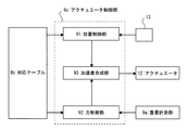
- the actuator controller 9c includes a position controller 91, a force controller 92, and an acceleration synthesizer 93 as shown in FIG. It can be expressed as a control law.
- the actuator controller 9c controls the linear actuator 12 to hold the container support means 5 at a specified height regardless of the container weight acting on the container support means 5.
- the designated height in this embodiment is registered in advance in the correspondence table 9b, and specifically, the upper surface of the container support means 5 is made to coincide with the height of the upper surfaces of the supply wheel 7 and the discharge wheel 8.
- the designated height from the supply position A to the discharge position F can be set constant.
- the position control unit 91 calculates a first acceleration signal from the designated height of the container support means 5 registered in the correspondence table 9b and the detected height of the container support means 5 detected by the height detection means 13. It is supposed to be.
- the container support means 5 is held at the specified height by the linear actuator 12 in a state where the weight acting on the container support means 5 does not change, such as the measurement positions B and E, for example. Therefore, there is no difference between the detected height and the specified height, and the first acceleration signal is zero.
- the linear actuator 12 is driven until just before.
- the position of the container 1 cannot be maintained constant with the driving force generated by the driving signal, and the container support means 5 is slightly lowered. Therefore, a difference is generated between the detected height and the specified height, and the first acceleration. A signal will be generated.
- the force control unit 92 calculates a second acceleration signal from the container weight calculated by the weight measuring unit 9a and the assumed weight acting on the container support means 5.
- the rotary table 4 is provided with an encoder (not shown) so that the position of each container support means 5 is recognized by the control means 9.
- an assumed weight acting on the container support means 5 at each position of the container support means 5 is registered.
- the assumed weight at the measurement position B corresponds to the weight of the empty container 1
- the assumed weight in the large throw section C and the small throw section D is filled with the filling liquid as the container support means 5 moves.
- the assumed weight at the measurement position E corresponds to the weight of the container 1 in which the empty container 1 is filled with a specified amount of filling liquid.
- the second acceleration signal is calculated from the actual container weight calculated by the weight measuring unit 9a and the assumed weight registered in the correspondence table 9b based on the position of the container support means 5. It has become. For example, when the container 1 is placed on the container support means 5 at the supply position A, the second acceleration signal is zero if there is no difference between the actual container weight and the assumed weight. On the other hand, for example, when the container 1 is not filled with the expected amount of filling liquid at a predetermined position in the small throwing section D, a difference occurs between the actual container weight and the assumed weight. 2 acceleration signals are generated.
- the acceleration synthesizer 93 calculates a drive signal to the linear actuator 12 from the obtained first acceleration signal and second acceleration signal, and drives the linear actuator 12 based on the drive signal.
- the calculated drive signal is to maintain the container support means 5 at the specified height regardless of the weight acting on the container support means 5, and by constantly calculating the drive signal, The specified height can be maintained from the supply position A to the discharge position F.
- the filling means 6 includes a filling nozzle 21 provided above the container 1 placed on the container support means 5, and a liquid supply pipe 22 disposed between a filling liquid tank (not shown) and the filling nozzle 21. And.
- the filling nozzle 21 has a valve (not shown) inside and is controlled by a filling portion 9d provided in the control means 9.
- the filling unit 9d controls the opening degree of the valve of the filling nozzle 21 in the large throwing section C and the small throwing section D on the basis of the weight of the container 1 measured by the weight measuring unit 9a to fill the filling liquid. To do.
- the filling liquid is supplied at a large flow rate to fill most of the container 1, and in the small throwing section D, the remaining portion is filled accurately at a small flow rate.
- the filling unit 9b recognizes that the container 1 is filled with a specified amount of the filling liquid while monitoring the weight of the container 1 measured by the weight measuring unit 9a, the filling unit 9b closes the valve in the filling nozzle 21 to fill the filling liquid. Finish filling.
- the height detecting means 13 always detects the height of the drive shaft 11 of the linear actuator 12, and the weight measuring unit 9a detects the container supporting means 5 that is lowered by placing the container 1 on the correspondence table 9b.
- the weight of the container acting on the container support means 5 is recognized from the height and the drive signal of the linear actuator 12 at this time, in other words, the drive signal that has been driving the linear actuator 12 just before the container 1 is placed. .
- the actuator control section 9c of the control means 9 obtains the first acceleration signal from the detected height detected by the height detecting means 13 and the preset designated height, and the container obtained by the weight measuring section 9a.
- a second acceleration signal is obtained from the weight and the assumed weight at the supply position A retrieved from the correspondence table 9b, and the drive signal is calculated by adding the first and second acceleration signals.
- the actuator control section 9c drives the linear actuator 12 by the calculated drive signal, so that the container support means 5 on which the empty container 1 is placed moves to the specified height.
- the filling section 9d the weight of the empty container 1 measured by the weight measuring section 9a is determined and the filling of the filling liquid is started while the container support means 5 moves in the measurement position B. Perform a zero reset of the weight.
- the height detection and weight detection operations are always performed regardless of whether or not the container 1 is placed on the container support means 5, and the height detection and weight detection are performed on the container support means 5 by increasing the sampling frequency.
- the weight of the placed container 1 can be quickly measured.
- the interval from the supply position A to the measurement position B and the interval from the discharge position F to the measurement position E for measuring the weight of the container 1 set on the rotary table 4 can be set short.
- a robust strain gauge is used to measure the weight of the container 1, and the weight of the container 1 can be accurately measured without waiting for convergence of the vibration of the Roval.
- the weight cannot be measured immediately after the container 1 is supplied or immediately after the filling is completed, and it is necessary to set a long interval until the weight is measured.
- a weight filling apparatus having the same processing capacity if the interval until measurement is set long, it becomes necessary to increase the diameter of the rotary table 4, which causes a problem that the installation space for the equipment increases. .
- the diameter of the turntable 4 is the same, the distance of the filling section has to be set shorter by the amount set for the longer interval until measurement, so the turntable 4 must be rotated at a low speed. The processing capacity will be reduced.
- the filling portion 9d of the control means 9 opens the valve of the filling nozzle 21 of the filling means 6 and the container 1
- the filling of the filling liquid is started.
- the filling liquid is filled into the container 1 with a large flow rate, and most of the capacity of the container 1 is filled.
- the small throw section D the filling liquid measured by the weight measuring unit 9a is filled. Fill the container 1 with a small flow rate while measuring the weight.
- the small pitch section D can be omitted.
- the filling unit 9d closes the valve of the filling nozzle 21 and finishes filling the filling liquid.
- the weight acting on the container support means 5 increases with the filling of the filling liquid, and thereby the container support means 5 tends to descend.
- the correspondence table 9b of the control means 9 an assumed weight is registered based on the filling amount of the filling liquid at each position of the rotary table 4, and in the actuator control unit 9c, the container weight obtained by the weight measuring unit 9a, A second acceleration signal is calculated from the assumed weight at each position of the container 1. Further, the actuator control section 9c calculates a drive signal from the first acceleration signal obtained from the detected height detected by the height detecting means 13 and the specified height and the calculated second acceleration signal, and the linear signal is calculated. The actuator 12 is driven to maintain the container support means 5 at a specified height.
- the actuator control section 9c maintains the container support means 5 at a specified height, and the container 1 is moved in the horizontal direction at the discharge position F, whereby the container 1 is moved to the discharge wheel 8. It is possible to pass to.
- the position of the container 1 is lowered as the weight of the container 1 increases, and therefore the height of the container support means 5 at the supply position A is described above. Compared to the above, the height of the container support means 5 at the discharge position F becomes lower. Therefore, conventionally, adjustments such as setting the height of the discharge wheel 8 to be lower than the height of the supply wheel 7 are necessary, and there is a problem that adjustment of the filling line 2 becomes complicated.
- the filling material is not limited to the liquid, and may be a powder, a solid, or the like.
- the present invention is not limited to the examples.
- the container 1 is supported on the upper surface of the container support means 5 in the above embodiment, a neck gripper that grips and transports the neck of the container 1 may be used as the container support means. Even in this case, the weight of the container can be quickly measured by providing the drive shaft 11 and the linear actuator 12 on the neck gripper, and the neck gripper can be maintained at a certain designated height, In addition, delivery to and from the discharge side can be performed smoothly.
- the rotation type weight type filling apparatus provided with the turntable was demonstrated, it is not restricted to a rotation type, It is not limited to a rotation type, It is a line type weight type filling apparatus which conveys and processes the container 1 linearly. Is also applicable.
- the designated height of the said container support means 5 is set constant, it does not necessarily need to be constant, for example, the designated height in the supply position A with the said supply wheel 7 is set to supply wheel. 7 may be positioned slightly lower than the height of the upper surface of 7. By doing so, it is possible to prevent catching when the container 1 is moved from the supply wheel 7 to the container support means 5.
- the specified height at the discharge position F to the discharge wheel 8 is positioned slightly higher than the height of the upper surface of the discharge wheel 8 so that the container 1 is caught when moving to the discharge wheel 8. Can be prevented.
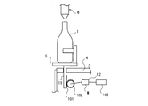
- the linear actuator 12 constituted by the drive shaft 11 made of magnet and the coil 12a is used, but the rack 101 provided on the drive shaft 11 as shown in FIG. And the pinion 102 driven by the motor can be used.
- an encoder 103 provided in the motor M can be used as the height detection means 13.
Landscapes
- Physics & Mathematics (AREA)
- General Physics & Mathematics (AREA)
- Engineering & Computer Science (AREA)
- Mechanical Engineering (AREA)
- Electromagnetism (AREA)
- Basic Packing Technique (AREA)
- Filling Of Jars Or Cans And Processes For Cleaning And Sealing Jars (AREA)
Abstract
重量計測手段が計測した容器重量に基づいて充填手段6を制御する重量充填装置3に関する。 容器支持手段5に連結された駆動軸11を駆動するリニアアクチュエータ12を備え、 重量計測部9a(重量計測手段)は、高さ検出手段13が検出した駆動軸11の検出高さと、当該検出高さにおける上記リニアアクチュエータ12の駆動信号とから容器重量を求め、 予め設定された容器支持手段5の指定高さと、上記高さ検出手段13が検出した検出高さとから第1の加速度信号を算出し、上記重量計測部9aが求めた容器重量と、上記容器支持手段5に作用する想定される想定重量とから第2の加速度信号を算出し、上記第1、第2の加速度信号から算出した駆動信号によって容器支持手段5を指定高さに維持する。 容器重量の計測を迅速に行うことができ、容器の受け渡しの際のトラブルを可及的に防止することができる。
Description
本発明は重量充填装置に関し、詳しくは容器支持手段に支持された容器の重量を重量計測手段によって計測しながら被充填物の充填を行う重量充填装置に関する。
従来、容器を支持する容器支持手段と、各容器支持手段に支持された容器の重量を計測する重量計測手段と、上記容器支持手段に支持された容器に被充填物を供給する充填手段と、上記重量計測手段からの信号に基づいて上記充填手段を制御する制御手段とを備えた重量充填装置が知られている(特許文献1)。
この特許文献1における重量充填装置では、上記重量計測手段にひずみゲージを用いており、当該ひずみゲージの変形を計測することで容器に充填される被充填物の重量を計測するものとなっている。
また容器に被充填物を充填する充填装置では、容器支持手段への容器の供給および排出の際には、容器を水平方向に移動させて受け渡す方法が一般的となっている。
この特許文献1における重量充填装置では、上記重量計測手段にひずみゲージを用いており、当該ひずみゲージの変形を計測することで容器に充填される被充填物の重量を計測するものとなっている。
また容器に被充填物を充填する充填装置では、容器支持手段への容器の供給および排出の際には、容器を水平方向に移動させて受け渡す方法が一般的となっている。
しかしながら、上記重量計測手段にひずみゲージを用いた場合、上記容器支持手段で容器を支持した直後や、容器への被充填物の充填完了直後は、上記ひずみゲージの振動が収束するまで正確な容器の重量が測定できないという問題がある。
また容器支持手段への容器の供給および排出の際に、容器を水平方向に移動させて供給側または排出側への移載を行う場合、上記容器支持手段の高さにばらつきがあると、上記容器の受け渡しの際に容器が引っ掛かるなどのトラブルが発生する恐れがある。
このような問題に鑑み、本発明は容器重量の計測を迅速に行うことができ、また容器の受け渡しの際のトラブルを可及的に防止することが可能な重量充填装置を提供するものである。
また容器支持手段への容器の供給および排出の際に、容器を水平方向に移動させて供給側または排出側への移載を行う場合、上記容器支持手段の高さにばらつきがあると、上記容器の受け渡しの際に容器が引っ掛かるなどのトラブルが発生する恐れがある。
このような問題に鑑み、本発明は容器重量の計測を迅速に行うことができ、また容器の受け渡しの際のトラブルを可及的に防止することが可能な重量充填装置を提供するものである。
すなわち請求項1の発明にかかる重量充填装置は、容器を支持する容器支持手段と、各容器支持手段に支持された容器の重量を計測する重量計測手段と、上記容器支持手段に支持された容器に被充填物を供給する充填手段と、上記重量計測手段が計測した容器重量に基づいて上記充填手段を制御する制御手段とを備えた重量充填装置において、
上記容器支持手段に連結された駆動軸と、当該駆動軸を駆動するアクチュエータと、上記容器支持手段の高さを検出する高さ検出手段とを備え、
上記重量計測手段は、上記高さ検出手段が検出した検出高さと当該検出高さにおける上記アクチュエータの駆動信号とから容器重量を求め、
上記制御手段は、予め設定された容器支持手段の指定高さと、上記高さ検出手段が検出した上記検出高さとから第1の加速度信号を算出するとともに、
上記重量計測手段が求めた容器重量と、上記容器支持手段に作用する想定される想定重量とから第2の加速度信号を算出し、
上記第1の加速度信号と第2の加速度信号とから、上記容器支持手段を上記指定高さに維持するための上記駆動信号を算出して、当該駆動信号に基づいてアクチュエータを駆動することを特徴としている。
請求項2の発明は、請求項1に記載された重量充填装置において、上記アクチュエータは、上記容器支持手段の底面に固定された棒状の磁石からなる上記駆動軸と、当該駆動軸を囲繞するとともに制御手段からの駆動信号によって磁力を発生するコイルとから構成されることを特徴としている。
上記容器支持手段に連結された駆動軸と、当該駆動軸を駆動するアクチュエータと、上記容器支持手段の高さを検出する高さ検出手段とを備え、
上記重量計測手段は、上記高さ検出手段が検出した検出高さと当該検出高さにおける上記アクチュエータの駆動信号とから容器重量を求め、
上記制御手段は、予め設定された容器支持手段の指定高さと、上記高さ検出手段が検出した上記検出高さとから第1の加速度信号を算出するとともに、
上記重量計測手段が求めた容器重量と、上記容器支持手段に作用する想定される想定重量とから第2の加速度信号を算出し、
上記第1の加速度信号と第2の加速度信号とから、上記容器支持手段を上記指定高さに維持するための上記駆動信号を算出して、当該駆動信号に基づいてアクチュエータを駆動することを特徴としている。
請求項2の発明は、請求項1に記載された重量充填装置において、上記アクチュエータは、上記容器支持手段の底面に固定された棒状の磁石からなる上記駆動軸と、当該駆動軸を囲繞するとともに制御手段からの駆動信号によって磁力を発生するコイルとから構成されることを特徴としている。
上記請求項1の発明によれば、上記容器支持手段をアクチュエータを用いて駆動し、容器支持手段の検出高さと、アクチュエータの駆動信号とから容器重量を算出することで、上記特許文献1のようなひずみゲージの振動が収束するまでの待機時間が不要となり、より迅速な計測が可能となった。
また、アクチュエータを駆動させて上記容器支持手段を上記指定高さに維持するため、上記容器支持手段への容器の供給および排出の際に、供給側および排出側との間の高低差をなくすことができ、もしくは受渡側を受け取り側より若干高くすることにより容器の引っ掛かりをなくし、受け渡しの際のトラブルを防止することができる。
さらに請求項2の発明によれば、上記アクチュエータを棒状の磁石からなる駆動軸とコイルとによって構成することにより、摩擦による計測への影響をなくすことができる。
また、アクチュエータを駆動させて上記容器支持手段を上記指定高さに維持するため、上記容器支持手段への容器の供給および排出の際に、供給側および排出側との間の高低差をなくすことができ、もしくは受渡側を受け取り側より若干高くすることにより容器の引っ掛かりをなくし、受け渡しの際のトラブルを防止することができる。
さらに請求項2の発明によれば、上記アクチュエータを棒状の磁石からなる駆動軸とコイルとによって構成することにより、摩擦による計測への影響をなくすことができる。
図示実施例について本発明を説明すると、図1はびんなどの容器1に充填液を充填する充填ライン2を示し、図2は上記容器1に充填液を充填する重量充填装置3の断面図を示している。
上記重量充填装置3は、回転可能に設けられた回転テーブル4と、当該回転テーブル4の円周方向に沿って等間隔に設けられた容器支持手段5と、上記容器支持手段5に支持された容器1に充填液を充填する充填手段6とを備え、回転テーブル4の回転によって容器支持手段5に支持された容器1と充填手段6とが一体的に回転しつつ充填を行うようになっている。
上記充填ライン2において、上記回転テーブル4の上流側には供給ホイール7が設けられるとともに、下流側には排出ホイール8が設けられており、上記回転テーブル4と上記供給ホイール7とが隣接した供給位置Aと、排出ホイール8と隣接した排出位置Fとにおいて、容器1の受け渡しが行われるようになっている。
上記重量充填装置3は制御手段9の制御によって動作するようになっており、上記供給位置Aと排出位置Fとの間で上記充填手段6を作動させることで、容器1への充填液の充填が行われるようになっている。
具体的に、上記供給位置Aの下流側に設定された大投区間Cでは、上記充填手段6が容器1に対して充填液を大流量で充填し、当該大投区間Cの下流側に設定された小投区間Dでは小流量で充填液を充填するようになっている。
また上記供給位置Aの下流に設定された計測位置Bでは、上記供給位置Aで供給された空の容器1の重量を計測するとともに、これから充填される充填液の重量を計測するためのゼロリセットを行う。
そして上記小投区間Dの下流に設定された計測位置Eでは、上記大投区間Cおよび小投区間Dにおいて充填された充填液の重量を計測するようになっている。
上記重量充填装置3は、回転可能に設けられた回転テーブル4と、当該回転テーブル4の円周方向に沿って等間隔に設けられた容器支持手段5と、上記容器支持手段5に支持された容器1に充填液を充填する充填手段6とを備え、回転テーブル4の回転によって容器支持手段5に支持された容器1と充填手段6とが一体的に回転しつつ充填を行うようになっている。
上記充填ライン2において、上記回転テーブル4の上流側には供給ホイール7が設けられるとともに、下流側には排出ホイール8が設けられており、上記回転テーブル4と上記供給ホイール7とが隣接した供給位置Aと、排出ホイール8と隣接した排出位置Fとにおいて、容器1の受け渡しが行われるようになっている。
上記重量充填装置3は制御手段9の制御によって動作するようになっており、上記供給位置Aと排出位置Fとの間で上記充填手段6を作動させることで、容器1への充填液の充填が行われるようになっている。
具体的に、上記供給位置Aの下流側に設定された大投区間Cでは、上記充填手段6が容器1に対して充填液を大流量で充填し、当該大投区間Cの下流側に設定された小投区間Dでは小流量で充填液を充填するようになっている。
また上記供給位置Aの下流に設定された計測位置Bでは、上記供給位置Aで供給された空の容器1の重量を計測するとともに、これから充填される充填液の重量を計測するためのゼロリセットを行う。
そして上記小投区間Dの下流に設定された計測位置Eでは、上記大投区間Cおよび小投区間Dにおいて充填された充填液の重量を計測するようになっている。
上記容器支持手段5は、その上面で容器1を下方から支持するとともに、当該容器支持手段5の上部に設けられた支持部材5aによって容器1を側方から支持するようになっている。
上記供給ホイール7との供給位置Aでは、供給ホイール7に載置された容器1が水平方向に移動されて、上記容器支持手段5上に移載されるようになっており、これと同様、排出ホイール8との排出位置Fでも、容器支持手段5に載置された容器1が水平方向に移動されて、排出ホイール8に移載されるようになっている。
このとき、容器支持手段5の上面と、上記供給ホイール7や排出ホイール8の上面との間に高低差があると、容器1の移載の際に倒びんなどのトラブルが発生するため、上記容器支持手段5の上面の高さを供給ホイール7および排出ホイール8の上面に一致させることが望ましい。
上記供給ホイール7との供給位置Aでは、供給ホイール7に載置された容器1が水平方向に移動されて、上記容器支持手段5上に移載されるようになっており、これと同様、排出ホイール8との排出位置Fでも、容器支持手段5に載置された容器1が水平方向に移動されて、排出ホイール8に移載されるようになっている。
このとき、容器支持手段5の上面と、上記供給ホイール7や排出ホイール8の上面との間に高低差があると、容器1の移載の際に倒びんなどのトラブルが発生するため、上記容器支持手段5の上面の高さを供給ホイール7および排出ホイール8の上面に一致させることが望ましい。
上記容器支持手段5の下部には、当該容器支持手段5の底面に固定された丸棒状もしくは角棒状の磁石からなる駆動軸11が設けられ、上記回転テーブル4には上記駆動軸11を囲繞するとともに制御手段9からの駆動信号によって磁力を発生するコイル12aとから構成されたリニアアクチュエータ12が設けられている。
上記リニアアクチュエータ12についての具体的な構成や動作については説明を省略するが、上記コイル12aに駆動信号としての電流を印加することにより、上記駆動軸11を駆動することが可能となっており、本実施例ではこの駆動力を上記容器支持手段5および当該容器支持手段5に載置された容器1の位置を一定に維持するために利用するようになっている。
上記駆動軸11は上記コイル12aの下方に突出するように設けられ、上記回転テーブル4には当該駆動軸11の位置を検出して、当該検出高さを上記制御手段9に送信する高さ検出手段13が設けられている。
上記高さ検出手段13としては、容器支持手段5の高さを高精度に検出することができ、かつサンプリング周波数の高いセンサを使用することが望ましい。
上記リニアアクチュエータ12についての具体的な構成や動作については説明を省略するが、上記コイル12aに駆動信号としての電流を印加することにより、上記駆動軸11を駆動することが可能となっており、本実施例ではこの駆動力を上記容器支持手段5および当該容器支持手段5に載置された容器1の位置を一定に維持するために利用するようになっている。
上記駆動軸11は上記コイル12aの下方に突出するように設けられ、上記回転テーブル4には当該駆動軸11の位置を検出して、当該検出高さを上記制御手段9に送信する高さ検出手段13が設けられている。
上記高さ検出手段13としては、容器支持手段5の高さを高精度に検出することができ、かつサンプリング周波数の高いセンサを使用することが望ましい。
上記制御手段9には重量計測手段としての重量計測部9aが設けられており、上記リニアアクチュエータ12からの駆動信号と、上記高さ検出手段13が検出した検出高さとから、上記容器支持手段5に作用する重量を測定するようになっている。
また制御手段9には、上記容器支持手段5の高さと、容器支持手段5に作用する重量とをそれぞれ異ならせた場合における、上記リニアアクチュエータ12を駆動させるための駆動信号を計測した結果が、対応テーブル9bとして登録されている。
これにより、上記高さ検出手段13が検出した容器支持手段5の検出高さと、その際にリニアアクチュエータ12を駆動する駆動信号とが判明すれば、上記重量計測部9aは上記対応テーブル9bから容器支持手段5に作用する重量、すなわち容器重量を得ることが可能となっている。
なお以下の説明において、容器重量としては上記容器支持手段5に容器1が載置されていない状態の、容器支持手段5自体の重量を計測した結果も含むものとする。
また制御手段9には、上記容器支持手段5の高さと、容器支持手段5に作用する重量とをそれぞれ異ならせた場合における、上記リニアアクチュエータ12を駆動させるための駆動信号を計測した結果が、対応テーブル9bとして登録されている。
これにより、上記高さ検出手段13が検出した容器支持手段5の検出高さと、その際にリニアアクチュエータ12を駆動する駆動信号とが判明すれば、上記重量計測部9aは上記対応テーブル9bから容器支持手段5に作用する重量、すなわち容器重量を得ることが可能となっている。
なお以下の説明において、容器重量としては上記容器支持手段5に容器1が載置されていない状態の、容器支持手段5自体の重量を計測した結果も含むものとする。
そして上記制御手段9は上記リニアアクチュエータ12を制御するアクチュエータ制御部9cを備え、図3に示すようにアクチュエータ制御部9cは位置制御部91と、力制御部92と、加速度合成部93とを含む制御則として表することができる。
またアクチュエータ制御部9cは、上記リニアアクチュエータ12を制御することにより、上記容器支持手段5に作用する容器重量にかかわらず、当該容器支持手段5を指定高さに保持させるものとなっている。
ここで、本実施例における指定高さは上記対応テーブル9bに予め登録されており、具体的には容器支持手段5の上面を上記供給ホイール7および排出ホイール8の上面の高さに一致させた高さであって、上記供給位置Aから排出位置Fにかけて指定高さを一定に設定することができる。
またアクチュエータ制御部9cは、上記リニアアクチュエータ12を制御することにより、上記容器支持手段5に作用する容器重量にかかわらず、当該容器支持手段5を指定高さに保持させるものとなっている。
ここで、本実施例における指定高さは上記対応テーブル9bに予め登録されており、具体的には容器支持手段5の上面を上記供給ホイール7および排出ホイール8の上面の高さに一致させた高さであって、上記供給位置Aから排出位置Fにかけて指定高さを一定に設定することができる。
上記位置制御部91は、上記対応テーブル9bに登録された容器支持手段5の指定高さと、上記高さ検出手段13が検出した容器支持手段5の検出高さとから、第1の加速度信号を算出するようになっている。
上記第1の加速度信号は、例えば上記計測位置B、Eなど、容器支持手段5に作用する重量に変化がない状態では、容器支持手段5は上記リニアアクチュエータ12によって上記指定高さに保持されるため、上記検出高さと指定高さとの差は生じず、上記第1の加速度信号はゼロとなる。
これに対し、例えば上記供給位置Aや大投区間Cなど、容器支持手段5に容器1が載置されたり、容器1に充填液が充填される状態では、直前までリニアアクチュエータ12を駆動していた駆動信号による駆動力では容器1の位置を一定に維持することができず、容器支持手段5が微小に下降するため、検出高さと指定高さとの間に差が生じて上記第1の加速度信号が発生することとなる。
上記第1の加速度信号は、例えば上記計測位置B、Eなど、容器支持手段5に作用する重量に変化がない状態では、容器支持手段5は上記リニアアクチュエータ12によって上記指定高さに保持されるため、上記検出高さと指定高さとの差は生じず、上記第1の加速度信号はゼロとなる。
これに対し、例えば上記供給位置Aや大投区間Cなど、容器支持手段5に容器1が載置されたり、容器1に充填液が充填される状態では、直前までリニアアクチュエータ12を駆動していた駆動信号による駆動力では容器1の位置を一定に維持することができず、容器支持手段5が微小に下降するため、検出高さと指定高さとの間に差が生じて上記第1の加速度信号が発生することとなる。
次に上記力制御部92は、上記重量計測部9aが算出した容器重量と、上記容器支持手段5に作用する想定される想定重量とから第2の加速度信号を算出するようになっている。
上記回転テーブル4には図示しないエンコーダが設けられ、各容器支持手段5の位置を上記制御手段9によって認識するようになっている。また制御手段9の上記対応テーブル9bには、上記容器支持手段5の各位置において当該容器支持手段5に作用する想定重量が登録されている。
具体的に、上記計測位置Bにおける想定重量は空の容器1の重量に相当し、上記大投区間Cや小投区間Dにおける想定重量は、容器支持手段5が移動するにつれて充填液が充填される容器1の重量に相当し、計測位置Eにおける想定重量は、空の容器1に規定量の充填液が充填された容器1の重量に相当することとなる。
そして上記第2の加速度信号は、上記重量計測部9aが算出した実際の容器重量と、上記容器支持手段5の位置に基づいて対応テーブル9bに登録されている想定重量とから算出されるようになっている。
例えば、供給位置Aで容器支持手段5に容器1が載置された際に、実際の容器重量と想定重量との間に差がなければ、上記第2の加速度信号はゼロとなる。これに対し、例えば小投区間Dの所定の位置において容器1に想定された量の充填液が充填されなかった場合には、実際の容器重量と想定重量との間に差が生じて上記第2の加速度信号が発生することとなる。
上記回転テーブル4には図示しないエンコーダが設けられ、各容器支持手段5の位置を上記制御手段9によって認識するようになっている。また制御手段9の上記対応テーブル9bには、上記容器支持手段5の各位置において当該容器支持手段5に作用する想定重量が登録されている。
具体的に、上記計測位置Bにおける想定重量は空の容器1の重量に相当し、上記大投区間Cや小投区間Dにおける想定重量は、容器支持手段5が移動するにつれて充填液が充填される容器1の重量に相当し、計測位置Eにおける想定重量は、空の容器1に規定量の充填液が充填された容器1の重量に相当することとなる。
そして上記第2の加速度信号は、上記重量計測部9aが算出した実際の容器重量と、上記容器支持手段5の位置に基づいて対応テーブル9bに登録されている想定重量とから算出されるようになっている。
例えば、供給位置Aで容器支持手段5に容器1が載置された際に、実際の容器重量と想定重量との間に差がなければ、上記第2の加速度信号はゼロとなる。これに対し、例えば小投区間Dの所定の位置において容器1に想定された量の充填液が充填されなかった場合には、実際の容器重量と想定重量との間に差が生じて上記第2の加速度信号が発生することとなる。
そして加速度合成部93は、得られた上記第1の加速度信号と第2の加速度信号とから、上記リニアアクチュエータ12への駆動信号を算出し、当該駆動信号に基づいてリニアアクチュエータ12を駆動させる。
算出された駆動信号は、容器支持手段5に作用する重量にかかわらず、当該容器支持手段5を上記指定高さに維持させるものとなっており、上記駆動信号を常時算出し続けることで、上記供給位置Aから排出位置Fまで上記指定高さを維持することが可能となっている。
算出された駆動信号は、容器支持手段5に作用する重量にかかわらず、当該容器支持手段5を上記指定高さに維持させるものとなっており、上記駆動信号を常時算出し続けることで、上記供給位置Aから排出位置Fまで上記指定高さを維持することが可能となっている。
上記充填手段6は、上記容器支持手段5に載置された容器1の上方に設けられた充填ノズル21と、図示しない充填液タンクと充填ノズル21との間に配設された給液管22とを備えている。
上記充填ノズル21は内部に図示しないバルブを備え、上記制御手段9に設けられた充填部9dによって制御されるようになっている。上記充填部9dは上記重量計測部9aが計測した容器1の重量に基づいて、上記大投区間Cおよび小投区間Dにおいて上記充填ノズル21のバルブの開度を制御し、充填液の充填を行うようになっている。
ここで、大投区間Cでは大きな流量で充填液を供給して容器1の大部分の充填を行い、また小投区間Dでは小さな流量で残りの部分を正確に充填するようになっている。
そして充填部9bは、上記重量計測部9aが測定した容器1の重量を監視しながら、容器1に規定量の充填液が充填されたと認識すると、充填ノズル21内のバルブを閉鎖して充填液の充填を終了させる。
上記充填ノズル21は内部に図示しないバルブを備え、上記制御手段9に設けられた充填部9dによって制御されるようになっている。上記充填部9dは上記重量計測部9aが計測した容器1の重量に基づいて、上記大投区間Cおよび小投区間Dにおいて上記充填ノズル21のバルブの開度を制御し、充填液の充填を行うようになっている。
ここで、大投区間Cでは大きな流量で充填液を供給して容器1の大部分の充填を行い、また小投区間Dでは小さな流量で残りの部分を正確に充填するようになっている。
そして充填部9bは、上記重量計測部9aが測定した容器1の重量を監視しながら、容器1に規定量の充填液が充填されたと認識すると、充填ノズル21内のバルブを閉鎖して充填液の充填を終了させる。
上記構成を有する充填ライン2の動作について説明すると、最初に空の容器1が上記供給ホイール7を搬送され、上記回転テーブル4に隣接した供給位置Aにおいて、供給ホイール7から回転テーブル4へと容器1が受け渡される。
このとき、上記回転テーブル4の供給位置Aに位置した容器支持手段5は、上記リニアアクチュエータ12によって指定高さに位置しており、この状態で供給ホイール7から容器1が水平方向に移動されて容器支持手段5上に載置される。
その結果、上記容器支持手段5には空の容器1の重量が作用し、リニアアクチュエータ12はそれまでの駆動信号では容器支持手段5を上記指定高さに維持しきれないことから、容器支持手段5が微小に下降することとなる。
上記高さ検出手段13ではリニアアクチュエータ12の駆動軸11の高さを常時検出しており、重量計測部9aは上記対応テーブル9bから、容器1が載置されて下降した容器支持手段5の検出高さと、この時のリニアアクチュエータ12の駆動信号、換言すると容器1が載置される直前まで当該リニアアクチュエータ12を駆動していた駆動信号とから、容器支持手段5に作用した容器重量を認識する。
このとき、上記回転テーブル4の供給位置Aに位置した容器支持手段5は、上記リニアアクチュエータ12によって指定高さに位置しており、この状態で供給ホイール7から容器1が水平方向に移動されて容器支持手段5上に載置される。
その結果、上記容器支持手段5には空の容器1の重量が作用し、リニアアクチュエータ12はそれまでの駆動信号では容器支持手段5を上記指定高さに維持しきれないことから、容器支持手段5が微小に下降することとなる。
上記高さ検出手段13ではリニアアクチュエータ12の駆動軸11の高さを常時検出しており、重量計測部9aは上記対応テーブル9bから、容器1が載置されて下降した容器支持手段5の検出高さと、この時のリニアアクチュエータ12の駆動信号、換言すると容器1が載置される直前まで当該リニアアクチュエータ12を駆動していた駆動信号とから、容器支持手段5に作用した容器重量を認識する。
続いて、制御手段9のアクチュエータ制御部9cは、上記高さ検出手段13が検出した検出高さとあらかじめ設定された指定高さとから第1の加速度信号を求め、また重量計測部9aが求めた容器重量と、上記対応テーブル9bより検索した上記供給位置Aにおける想定重量とから第2の加速度信号を求め、これら第1、第2の加速度信号を加算して駆動信号を算出する。
そしてアクチュエータ制御部9cは算出した駆動信号によりリニアアクチュエータ12を駆動させ、これにより空の容器1が載置された容器支持手段5は上記指定高さに移動することとなる。
また充填部9dでは、上記容器支持手段5が上記計測位置Bを移動する間に、上記重量計測部9aが測定した上記空の容器1の重量を確定して、充填液の充填を開始するための重量のゼロリセットを行う。
そしてアクチュエータ制御部9cは算出した駆動信号によりリニアアクチュエータ12を駆動させ、これにより空の容器1が載置された容器支持手段5は上記指定高さに移動することとなる。
また充填部9dでは、上記容器支持手段5が上記計測位置Bを移動する間に、上記重量計測部9aが測定した上記空の容器1の重量を確定して、充填液の充填を開始するための重量のゼロリセットを行う。
上記高さ検出、重量検出の動作は、容器支持手段5上に容器1が載置されているか否かにかかわらず常時行われ、またサンプリング周波数を高くすることにより、上記容器支持手段5に載置された容器1の重量の計測を迅速に行うことができる。換言すると上記回転テーブル4に設定した容器1の重量を計測するための供給位置Aから計測位置Bの間隔、および排出位置Fから計測位置Eの間隔を短く設定することができる。
これに対し、上記特許文献1に記載された重量充填装置3では、容器1の重量の計測にロバーバル式のひずみゲージを用いており、ロバーバルの振動の収束を待たないと正確な容器1の重量を計測することができないことから、容器1が供給された直後や充填が終了した直後は重量の計測をすることができず、重量を計測するまでの間隔を長く設定する必要があった。
同じ処理能力を有する重量充填装置において、計測するまでの間隔を長く設定した場合、回転テーブル4の直径を大きくする必要が出てくるため、設備の設置スペースが大きくなるという問題が生じることとなる。
一方、回転テーブル4の直径を同じとした場合には、計測するまでの間隔を長く設定した分だけ充填区間の距離を短く設定しなければならないことから、回転テーブル4を低速で回転させなければならず処理能力が下がることとなる。
さらに、上記ロバーバル式のひずみゲージの場合、回転テーブル4の回転による遠心力によるロバーバルの変形を考慮する必要があったが、本実施例のように上記リニアアクチュエータ12の駆動軸11をコイル12aに対して上下に移動可能に設けることで、容器支持手段5に作用する遠心力の影響がなくなるため、容器1の重量を計測する際に上記遠心力による誤差を修正する必要がない。
これに対し、上記特許文献1に記載された重量充填装置3では、容器1の重量の計測にロバーバル式のひずみゲージを用いており、ロバーバルの振動の収束を待たないと正確な容器1の重量を計測することができないことから、容器1が供給された直後や充填が終了した直後は重量の計測をすることができず、重量を計測するまでの間隔を長く設定する必要があった。
同じ処理能力を有する重量充填装置において、計測するまでの間隔を長く設定した場合、回転テーブル4の直径を大きくする必要が出てくるため、設備の設置スペースが大きくなるという問題が生じることとなる。
一方、回転テーブル4の直径を同じとした場合には、計測するまでの間隔を長く設定した分だけ充填区間の距離を短く設定しなければならないことから、回転テーブル4を低速で回転させなければならず処理能力が下がることとなる。
さらに、上記ロバーバル式のひずみゲージの場合、回転テーブル4の回転による遠心力によるロバーバルの変形を考慮する必要があったが、本実施例のように上記リニアアクチュエータ12の駆動軸11をコイル12aに対して上下に移動可能に設けることで、容器支持手段5に作用する遠心力の影響がなくなるため、容器1の重量を計測する際に上記遠心力による誤差を修正する必要がない。
上記空の容器1を支持した容器支持手段5が計測位置Bから大投区間Cに進入すると、制御手段9の充填部9dが上記充填手段6の充填ノズル21のバルブを開放して、容器1への充填液の充填を開始する。
上記大投区間Cでは、充填液を大流量で容器1に充填させ、当該容器1の容量の大部分を充填し、その後の小投区間Dにおいて、上記重量計測部9aが測定した充填液の重量を計測しながら、充填液を小流量で容器1に充填する。なお、上記小投区間Dについては省略することも可能である。
そして、容器1に規定量の充填液が充填されると、充填部9dは上記充填ノズル21のバルブを閉鎖させて、充填液の充填を終了させる。
上記大投区間Cでは、充填液を大流量で容器1に充填させ、当該容器1の容量の大部分を充填し、その後の小投区間Dにおいて、上記重量計測部9aが測定した充填液の重量を計測しながら、充填液を小流量で容器1に充填する。なお、上記小投区間Dについては省略することも可能である。
そして、容器1に規定量の充填液が充填されると、充填部9dは上記充填ノズル21のバルブを閉鎖させて、充填液の充填を終了させる。
上記大投区間Cや小投区間Dにおいて容器1に充填液を充填すると、充填液の充填に伴って容器支持手段5に作用する重量が増大し、これにより容器支持手段5は下降しようとする。
上記制御手段9の上記対応テーブル9bには、回転テーブル4の各位置における充填液の充填量に基づいて想定重量が登録され、アクチュエータ制御部9cでは、重量計測部9aが求めた容器重量と、容器1の各位置の想定重量とから第2の加速度信号を算出する。
さらにアクチュエータ制御部9cは、上記高さ検出手段13が検出した検出高さと上記指定高さとから求めた第1の加速度信号と、算出した第2の加速度信号とから駆動信号を算出し、上記リニアアクチュエータ12を駆動させて容器支持手段5を指定高さに維持するようになっている。
上記制御手段9の上記対応テーブル9bには、回転テーブル4の各位置における充填液の充填量に基づいて想定重量が登録され、アクチュエータ制御部9cでは、重量計測部9aが求めた容器重量と、容器1の各位置の想定重量とから第2の加速度信号を算出する。
さらにアクチュエータ制御部9cは、上記高さ検出手段13が検出した検出高さと上記指定高さとから求めた第1の加速度信号と、算出した第2の加速度信号とから駆動信号を算出し、上記リニアアクチュエータ12を駆動させて容器支持手段5を指定高さに維持するようになっている。
その後、容器1が上記小投区間Dから計測位置Eに移動すると、当該計測位置Eにおいて容器1に充填された充填液の重量が計測されるようになっている。
この時も、上記アクチュエータ制御部9cは容器支持手段5を指定高さに維持するようになっており、上記排出位置Fにおいて容器1を水平方向に移動させることで、当該容器1を排出ホイール8に受け渡すことが可能となっている。
ここで、従来のロバーバル式のひずみゲージを用いた構成の場合、容器1の重量の増大に伴って容器1の位置が下降してしまうため、上記供給位置Aでの容器支持手段5の高さに比べて、排出位置Fでの容器支持手段5の高さは低くなってしまう。
したがって、従来は上記排出ホイール8の高さを供給ホイール7の高さより低く設定するなどの調整が必要となっており、充填ライン2の調整が煩雑になるという問題があった。
この時も、上記アクチュエータ制御部9cは容器支持手段5を指定高さに維持するようになっており、上記排出位置Fにおいて容器1を水平方向に移動させることで、当該容器1を排出ホイール8に受け渡すことが可能となっている。
ここで、従来のロバーバル式のひずみゲージを用いた構成の場合、容器1の重量の増大に伴って容器1の位置が下降してしまうため、上記供給位置Aでの容器支持手段5の高さに比べて、排出位置Fでの容器支持手段5の高さは低くなってしまう。
したがって、従来は上記排出ホイール8の高さを供給ホイール7の高さより低く設定するなどの調整が必要となっており、充填ライン2の調整が煩雑になるという問題があった。
なお、上記実施例では容器に充填液を充填する場合を説明したが、被充填物としては液体に限らず粉体、固体等であってもよく、容器もボトル、袋、箱等であってもよく、実施例に限定されるものではない。
さらに、上記実施例では容器支持手段5の上面に容器1を支持するようになっているが、容器支持手段として容器1の首部を把持して搬送するネックグリッパを用いてもよい。
この場合であっても、上記ネックグリッパに上記駆動軸11およびリニアアクチュエータ12を設けることで容器重量を迅速に計測することができ、またネックグリッパを一定の指定高さに維持して、供給側および排出側との受け渡しを円滑に行うことができる。
また上記実施例では、回転テーブルを備えた回転タイプの重量式充填装置について説明したが、回転タイプに限るものではなく、容器1を直線状に搬送して処理するラインタイプの重量式充填装置にも適用可能である。
さらに、上記実施例では容器支持手段5の上面に容器1を支持するようになっているが、容器支持手段として容器1の首部を把持して搬送するネックグリッパを用いてもよい。
この場合であっても、上記ネックグリッパに上記駆動軸11およびリニアアクチュエータ12を設けることで容器重量を迅速に計測することができ、またネックグリッパを一定の指定高さに維持して、供給側および排出側との受け渡しを円滑に行うことができる。
また上記実施例では、回転テーブルを備えた回転タイプの重量式充填装置について説明したが、回転タイプに限るものではなく、容器1を直線状に搬送して処理するラインタイプの重量式充填装置にも適用可能である。
さらに、上記実施例では上記容器支持手段5の指定高さを一定に設定しているが、必ずしも一定にする必要はなく、例えば上記供給ホイール7との供給位置Aにおける指定高さを、供給ホイール7の上面の高さよりも若干下方に位置させてもよい。このようにすることで供給ホイール7から容器1を容器支持手段5に移動させる際の引っ掛かりを防止することができる。
逆に、上記排出ホイール8への排出位置Fにおける指定高さを、排出ホイール8の上面の高さよりも若干上方に位置させておくことで、容器1を排出ホイール8に移動させる際の引っ掛かりを防止することができる。
また、上記実施例では磁石からなる駆動軸11とコイル12aとによって構成されたリニアアクチュエータ12を用いているが、アクチュエータとして図4に示すような、駆動軸11に設けたラック101と、モータMによって駆動されるピニオン102とによって構成されたものを用いることができる。
この場合、上記高さ検出手段13としては上記モータMに設けたエンコーダ103を用いることができる。
逆に、上記排出ホイール8への排出位置Fにおける指定高さを、排出ホイール8の上面の高さよりも若干上方に位置させておくことで、容器1を排出ホイール8に移動させる際の引っ掛かりを防止することができる。
また、上記実施例では磁石からなる駆動軸11とコイル12aとによって構成されたリニアアクチュエータ12を用いているが、アクチュエータとして図4に示すような、駆動軸11に設けたラック101と、モータMによって駆動されるピニオン102とによって構成されたものを用いることができる。
この場合、上記高さ検出手段13としては上記モータMに設けたエンコーダ103を用いることができる。
1 容器 2 充填ライン
3 重量充填装置 4 回転テーブル
5 容器支持手段 6 充填手段
9 制御手段 9a 重量計測部
9b 対応テーブル 9c アクチュエータ制御部
9d 充填部 11 駆動軸
12 リニアアクチュエータ(アクチュエータ)
13 高さ検出手段 91 位置制御部
92 力制御部 93 加速度合成部
3 重量充填装置 4 回転テーブル
5 容器支持手段 6 充填手段
9 制御手段 9a 重量計測部
9b 対応テーブル 9c アクチュエータ制御部
9d 充填部 11 駆動軸
12 リニアアクチュエータ(アクチュエータ)
13 高さ検出手段 91 位置制御部
92 力制御部 93 加速度合成部
Claims (2)
- 容器を支持する容器支持手段と、各容器支持手段に支持された容器の重量を計測する重量計測手段と、上記容器支持手段に支持された容器に被充填物を供給する充填手段と、上記重量計測手段が計測した容器重量に基づいて上記充填手段を制御する制御手段とを備えた重量充填装置において、
上記容器支持手段に連結された駆動軸と、当該駆動軸を駆動するアクチュエータと、上記容器支持手段の高さを検出する高さ検出手段とを備え、
上記重量計測手段は、上記高さ検出手段が検出した検出高さと当該検出高さにおける上記アクチュエータの駆動信号とから容器重量を求め、
上記制御手段は、予め設定された容器支持手段の指定高さと、上記高さ検出手段が検出した上記検出高さとから第1の加速度信号を算出するとともに、
上記重量計測手段が求めた容器重量と、上記容器支持手段に作用する想定される想定重量とから第2の加速度信号を算出し、
上記第1の加速度信号と第2の加速度信号とから、上記容器支持手段を上記指定高さに維持するための上記駆動信号を算出して、当該駆動信号に基づいてアクチュエータを駆動することを特徴とする重量充填装置。 - 上記アクチュエータは、上記容器支持手段の底面に固定された棒状の磁石からなる上記駆動軸と、当該駆動軸を囲繞するとともに制御手段からの駆動信号によって磁力を発生するコイルとから構成されることを特徴とする請求項1に記載の重量充填装置。
Priority Applications (1)
| Application Number | Priority Date | Filing Date | Title |
|---|---|---|---|
| US17/053,492 US11220418B2 (en) | 2018-05-09 | 2019-04-17 | Weighing and filling apparatus |
Applications Claiming Priority (2)
| Application Number | Priority Date | Filing Date | Title |
|---|---|---|---|
| JP2018-090897 | 2018-05-09 | ||
| JP2018090897A JP7060796B6 (ja) | 2018-05-09 | 2018-05-09 | 重量充填装置 |
Publications (1)
| Publication Number | Publication Date |
|---|---|
| WO2019216144A1 true WO2019216144A1 (ja) | 2019-11-14 |
Family
ID=68467390
Family Applications (1)
| Application Number | Title | Priority Date | Filing Date |
|---|---|---|---|
| PCT/JP2019/016499 Ceased WO2019216144A1 (ja) | 2018-05-09 | 2019-04-17 | 重量充填装置 |
Country Status (3)
| Country | Link |
|---|---|
| US (1) | US11220418B2 (ja) |
| JP (1) | JP7060796B6 (ja) |
| WO (1) | WO2019216144A1 (ja) |
Cited By (1)
| Publication number | Priority date | Publication date | Assignee | Title |
|---|---|---|---|---|
| WO2022113162A1 (ja) * | 2020-11-24 | 2022-06-02 | 日本電気株式会社 | 情報処理装置、情報処理方法、情報処理システム及びコンピュータ読み取り可能な記憶媒体 |
Families Citing this family (1)
| Publication number | Priority date | Publication date | Assignee | Title |
|---|---|---|---|---|
| CN115818547B (zh) * | 2022-11-30 | 2025-09-19 | 今麦郎饮品股份有限公司 | 饮料机的智能检测系统 |
Citations (7)
| Publication number | Priority date | Publication date | Assignee | Title |
|---|---|---|---|---|
| JPS5270681A (en) * | 1975-12-08 | 1977-06-13 | Hatayama Seikoushiyo Kk | Gravity type liquid filling machine |
| JPS5761920A (en) * | 1980-09-30 | 1982-04-14 | Shimadzu Corp | Electronic balance serving as measurment of displacement |
| JPS6355096A (ja) * | 1986-08-27 | 1988-03-09 | 澁谷工業株式会社 | 回転式重量充填装置 |
| JPS6445291A (en) * | 1987-08-12 | 1989-02-17 | Shibuya Kogyo Co Ltd | Heavy filler |
| JPH03502372A (ja) * | 1988-11-21 | 1991-05-30 | イーストマン・コダック・カンパニー | 電磁バランスに使用するシールド方法 |
| JPH053936U (ja) * | 1991-07-05 | 1993-01-22 | 財団法人シツプ・アンド・オーシヤン財団 | 磁気浮力平衡重量計 |
| JP2011084323A (ja) * | 2009-10-19 | 2011-04-28 | Hitachi Zosen Corp | 充填設備 |
Family Cites Families (13)
| Publication number | Priority date | Publication date | Assignee | Title |
|---|---|---|---|---|
| SE345520B (ja) * | 1969-03-14 | 1972-05-29 | Aga Ab | |
| JPH0798521B2 (ja) * | 1986-08-20 | 1995-10-25 | 澁谷工業株式会社 | 回転式重量充填装置 |
| US5038839A (en) * | 1988-07-18 | 1991-08-13 | Takeda Chemical Industries, Ltd. | Filling apparatus |
| US5423216A (en) * | 1992-12-24 | 1995-06-13 | Shin-Etsu Chemical Co., Ltd. | Apparatus for automatically determining bulk specific gravity of powdery product |
| US6220312B1 (en) * | 1998-11-18 | 2001-04-24 | Shandor Motion Systems | Apparatus and method for container filling |
| JP4452904B2 (ja) * | 1999-07-27 | 2010-04-21 | 澁谷工業株式会社 | ウエイトフィラ |
| GB0509450D0 (en) * | 2005-05-10 | 2005-06-15 | Europlacer Ind Sas | Method and apparatus |
| US8096327B2 (en) * | 2007-08-09 | 2012-01-17 | Tungsten Capital Partners, Llc | Aerosol can filling system |
| DE502007006201D1 (de) * | 2007-09-20 | 2011-02-17 | Mettler Toledo Ag | Dosiervorrichtung und Dosiereinheit mit elektrostatischem Verschluss |
| DE102010032573A1 (de) * | 2010-07-28 | 2012-02-02 | Khs Gmbh | Füllmaschine |
| DE102012000758A1 (de) * | 2012-01-18 | 2013-07-18 | Khs Gmbh | Anlage sowie Verfahren zum Füllen von Behältern |
| JP2013230836A (ja) | 2012-04-27 | 2013-11-14 | Shibuya Kogyo Co Ltd | 重量式充填装置 |
| DE102014211515A1 (de) * | 2014-06-16 | 2015-12-17 | Francotyp-Postalia Gmbh | Wiegeverfahren, Anordnung zur Durchführung des Wiegeverfahrens sowie ein entsprechendes Computerprogramm und ein entsprechendes computerlesbares Speichermedium |
-
2018
- 2018-05-09 JP JP2018090897A patent/JP7060796B6/ja active Active
-
2019
- 2019-04-17 US US17/053,492 patent/US11220418B2/en active Active
- 2019-04-17 WO PCT/JP2019/016499 patent/WO2019216144A1/ja not_active Ceased
Patent Citations (7)
| Publication number | Priority date | Publication date | Assignee | Title |
|---|---|---|---|---|
| JPS5270681A (en) * | 1975-12-08 | 1977-06-13 | Hatayama Seikoushiyo Kk | Gravity type liquid filling machine |
| JPS5761920A (en) * | 1980-09-30 | 1982-04-14 | Shimadzu Corp | Electronic balance serving as measurment of displacement |
| JPS6355096A (ja) * | 1986-08-27 | 1988-03-09 | 澁谷工業株式会社 | 回転式重量充填装置 |
| JPS6445291A (en) * | 1987-08-12 | 1989-02-17 | Shibuya Kogyo Co Ltd | Heavy filler |
| JPH03502372A (ja) * | 1988-11-21 | 1991-05-30 | イーストマン・コダック・カンパニー | 電磁バランスに使用するシールド方法 |
| JPH053936U (ja) * | 1991-07-05 | 1993-01-22 | 財団法人シツプ・アンド・オーシヤン財団 | 磁気浮力平衡重量計 |
| JP2011084323A (ja) * | 2009-10-19 | 2011-04-28 | Hitachi Zosen Corp | 充填設備 |
Cited By (1)
| Publication number | Priority date | Publication date | Assignee | Title |
|---|---|---|---|---|
| WO2022113162A1 (ja) * | 2020-11-24 | 2022-06-02 | 日本電気株式会社 | 情報処理装置、情報処理方法、情報処理システム及びコンピュータ読み取り可能な記憶媒体 |
Also Published As
| Publication number | Publication date |
|---|---|
| JP7060796B6 (ja) | 2022-05-17 |
| US20210130146A1 (en) | 2021-05-06 |
| JP2019196206A (ja) | 2019-11-14 |
| JP7060796B2 (ja) | 2022-04-27 |
| US11220418B2 (en) | 2022-01-11 |
Similar Documents
| Publication | Publication Date | Title |
|---|---|---|
| JP6508489B2 (ja) | 充填された容器を監視するための方法、および充填された容器のための監視システム | |
| KR102454987B1 (ko) | 커피 원두 비례 공급 장치 | |
| JP4903237B2 (ja) | 分包機 | |
| CN107735353A (zh) | 用于用灌装产品灌装容器的设备和方法 | |
| JP6163215B2 (ja) | タブレットプレスの測定装置の較正及びバランシングのための装置及び方法 | |
| JP7604611B2 (ja) | 粉末噴出肉盛溶接のための粉末質量流量を測定するための方法および装置 | |
| JP7060796B2 (ja) | 重量充填装置 | |
| JP6865278B2 (ja) | タイヤ搬送装置、これを備えるタイヤ試験システム、及びタイヤ搬送方法 | |
| CN109625350A (zh) | 粉状乳化炸药小包装装填计量装置及其计量方法 | |
| US5905656A (en) | Method and apparatus for dispensing a liquid | |
| JP5640585B2 (ja) | 粉体供給方法及び粉体供給装置 | |
| JPH10120089A (ja) | タイマー式液体充填方法および装置 | |
| CN108871214A (zh) | 一种气门直径连续检测装置 | |
| US20110247720A1 (en) | Machine For Testing Container Capacity | |
| CN113928750A (zh) | 料位检测系统、搅拌站及料位检测方法 | |
| JP5705507B2 (ja) | 重量充填装置 | |
| JP2018083709A (ja) | 部品供給装置 | |
| JP4781256B2 (ja) | 充填量検査装置およびその方法 | |
| JPH08285657A (ja) | 液体の充填量補正方法と装置 | |
| JP4744978B2 (ja) | 重量式充填装置 | |
| JP3568277B2 (ja) | 液体充填方法 | |
| NL1027168C1 (nl) | Vulmachine, in het bijzonder voor het vullen van zakken met een sterk samendrukbaar bulkmateriaal, alsmede werkwijze voor het aanpassen van een vulmachine. | |
| KR20170041488A (ko) | 몰딩 파우더 공급방법 | |
| JP2817192B2 (ja) | 加圧式充填装置 | |
| JPS62270263A (ja) | 連続鋳造機におけるパウダ−投入量制御装置 |
Legal Events
| Date | Code | Title | Description |
|---|---|---|---|
| 121 | Ep: the epo has been informed by wipo that ep was designated in this application |
Ref document number: 19798962 Country of ref document: EP Kind code of ref document: A1 |
|
| NENP | Non-entry into the national phase |
Ref country code: DE |
|
| 122 | Ep: pct application non-entry in european phase |
Ref document number: 19798962 Country of ref document: EP Kind code of ref document: A1 |