WO2019215972A1 - ヘアアイロン及びヘアアイロンヘッド - Google Patents
ヘアアイロン及びヘアアイロンヘッド Download PDFInfo
- Publication number
- WO2019215972A1 WO2019215972A1 PCT/JP2019/004097 JP2019004097W WO2019215972A1 WO 2019215972 A1 WO2019215972 A1 WO 2019215972A1 JP 2019004097 W JP2019004097 W JP 2019004097W WO 2019215972 A1 WO2019215972 A1 WO 2019215972A1
- Authority
- WO
- WIPO (PCT)
- Prior art keywords
- region
- side wall
- openings
- hair
- iron
- Prior art date
- Legal status (The legal status is an assumption and is not a legal conclusion. Google has not performed a legal analysis and makes no representation as to the accuracy of the status listed.)
- Ceased
Links
Images


Classifications
-
- A—HUMAN NECESSITIES
- A45—HAND OR TRAVELLING ARTICLES
- A45D—HAIRDRESSING OR SHAVING EQUIPMENT; EQUIPMENT FOR COSMETICS OR COSMETIC TREATMENTS, e.g. FOR MANICURING OR PEDICURING
- A45D1/00—Curling-tongs, i.e. tongs for use when hot; Curling-irons, i.e. irons for use when hot; Accessories therefor
-
- A—HUMAN NECESSITIES
- A45—HAND OR TRAVELLING ARTICLES
- A45D—HAIRDRESSING OR SHAVING EQUIPMENT; EQUIPMENT FOR COSMETICS OR COSMETIC TREATMENTS, e.g. FOR MANICURING OR PEDICURING
- A45D1/00—Curling-tongs, i.e. tongs for use when hot; Curling-irons, i.e. irons for use when hot; Accessories therefor
- A45D1/02—Curling-tongs, i.e. tongs for use when hot; Curling-irons, i.e. irons for use when hot; Accessories therefor with means for internal heating, e.g. by liquid fuel
- A45D1/04—Curling-tongs, i.e. tongs for use when hot; Curling-irons, i.e. irons for use when hot; Accessories therefor with means for internal heating, e.g. by liquid fuel by electricity
-
- A—HUMAN NECESSITIES
- A45—HAND OR TRAVELLING ARTICLES
- A45D—HAIRDRESSING OR SHAVING EQUIPMENT; EQUIPMENT FOR COSMETICS OR COSMETIC TREATMENTS, e.g. FOR MANICURING OR PEDICURING
- A45D20/00—Hair drying devices; Accessories therefor
- A45D20/48—Hair-drying combs or hair-drying brushes, with internal heating means
- A45D20/50—Hair-drying combs or hair-drying brushes, with internal heating means and provision for an air stream
Definitions
- the present invention relates to a hair iron and a hair iron head.
- a hair iron is used as one of the tools used for hair styling.
- Non-Patent Documents 1 and 2 describe a tubular curling iron head, in which a brush is provided in a region on the front side of the outer surface and a heating plate is provided in a region on the back side of the outer surface. Yes.
- the hair iron is referred to as a hair iron brush and a hair iron with brush, respectively.
- Non-Patent Documents 1 and 2 can apply heat to the brush caught, but do not apply wind (warm or cold) to the hair during styling. Can not. Therefore, a user who wants to style while applying wind to the hair uses this type of hair iron and a dryer together. That is, the user performs hair styling with a hair iron in one hand and a dryer in the other hand. As a result, the user feels a burden every time hair styling is performed.
- An object of one embodiment of the present invention is to provide a hair iron that can be styled while applying wind to hair without using it together with a dryer.
- a hair iron in order to solve the above problems, includes an iron head having a cylindrical side wall sealed at one end, and a blower that supplies air to the iron head. It has.
- the iron head includes a brush provided in a first region which is a partial region along the axial direction of the side wall, and a second region which is a region different from the first region.
- a plurality of ribs provided along the circumferential direction of the side wall.
- a plurality of openings penetrating the side wall are formed in the second region.
- an iron head is an iron head having a cylindrical side wall that is part of a hair iron and sealed at one end.
- the ironing head includes a brush provided in a first region which is a partial region along the axial direction of the side wall, and a second region which is a region different from the first region.
- a plurality of ribs provided along the circumferential direction of the side wall.
- a plurality of openings penetrating the side wall are formed in the second region.
- the iron head which comprises some hair irons can be provided.
- (A) to (e) are a top view, a right side view, a front view, a left side view, and a rear view of the hair iron according to the first embodiment of the present invention, respectively.
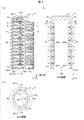
- (A) to (c) are a right side view, a longitudinal sectional view, and a transverse sectional view of an iron head provided in the hair iron shown in FIG. 1, respectively. It is a longitudinal cross-sectional view of the iron head which concerns on the 2nd Embodiment of this invention.
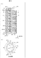
- (A) And (b) is the right view and cross-sectional view, respectively, of the iron head which concerns on the 3rd Embodiment of this invention.
- a hair iron 1 according to a first embodiment of the present invention will be described with reference to FIG. 1A to 1E are a top view, a right side view, a front view, a left side view, and a rear view of the hair iron 1, respectively.
- the figure at the time of seeing the hair iron 1 from the right side (the left side of the hair iron 1 in the state shown to (c) of FIG. 1) for the hair iron 1 is called a right view
- hair A view when the hair iron 1 is viewed from the left side (the right side of the hair iron 1 in the state shown in FIG. 1C) for the iron 1 is referred to as a left side view.
- the hair iron 1 includes an iron head 11, a main body 21, a blower 22, and an ion generator 23.
- the iron head 11 is an attachment suitable for hair styling designed to be detachable from the main body 21.
- the iron head 11 has a cylindrical side wall 112 in which one end (the end on the z-axis positive direction side in the coordinate system illustrated in FIG. 1C) is sealed by the end wall 111. Details of the iron head 11 will be described later with reference to FIG. A straight line A-A ′ shown in FIG. 1C shows the boundary between the iron head 11 and the main body 21.
- the axial direction of the cylindrical side wall 112 is defined as the z-axis direction
- the hair iron 1 when the hair iron 1 is viewed in plan view The direction from the right side to the left side is defined as the x-axis direction.
- the direction from the front side to the back side for the hair iron 1 is defined as the y-axis.
- a direction rotating around the axis about the z axis in the xy plane is referred to as a circumferential direction.
- the main body 21 is designed so that the iron head 11 can be attached to and detached from an end portion on the positive side of the z-axis which is one end portion thereof.
- the main body 21 also functions as a housing that houses the blower 22, the ion generator 23, and the heating device 24.
- the blower 22, the ion generator 23, and the heating device 24 are schematically shown only in FIG. 1D, and are not shown in FIGS. 1A to 1C and 1E. is doing.
- a feeding cable 25 for feeding power to the blower 22, the ion generator 23, and the heating device 24 is provided at the other end of the main body 21 on the negative side in the z-axis direction.
- the blower 22 includes a motor that rotates the fan by the supplied power.
- the blower 22 generates a wind W that is a flow of air by rotating the motor using the supplied electric power.
- the ion generator 23 includes two discharge electrodes, an anode and a negative electrode.
- the ion generator 23 applies a high voltage between the anode and the negative electrode using the supplied power.
- a discharge is generated between the anode and the negative electrode, positive ions are generated around the anode, and negative ions are generated around the cathode.
- the ion generator 23 is configured so that positive ions (for example, H + (H 2 O) m (m is an arbitrary natural number)) and negative ions (for example, O 2 ⁇ (H 2 O) n (n is an arbitrary number) To generate a natural number)).
- the wind W generated by the blower 22 includes positive ions and negative ions generated by the ion generator 23. Therefore, the wind W is converted into a wind containing ions, that is, an ion wind WI by the ion generator 23.
- the ion generator 23 configured to generate both positive ions and negative ions has been described. However, the ion generator 23 may be configured to generate either positive ions or negative ions.
- the ion generator 23 is configured to generate clustered positive ions and clustered negative ions.
- the ion generator 23 provided in the hair iron 1 according to the embodiment of the present invention is an example of the charged particle generator described in the claims.
- the charged particle generator included in the hair iron 1 is a discharge device that generates at least one of electrons, ozone, radicals, and active species by discharge instead of ions generated by the ion generator 23. There may be.
- the ion wind WI thus converted from the wind W is supplied to the inside of the iron head 11 from the end on the negative side of the z axis, which is the other end of the iron head 11.
- the heating device 24 is a heater that generates heat by the supplied electric power, and includes a heater configured to be in thermal contact with the iron head 11.
- the heating device 24 heats the ironing head 11 by supplying the ironing head 11 with heat energy TE generated by causing the heater to generate heat using the supplied electric power.
- the iron head 11 has been described as being designed to be detachable from the main body 21.
- the hair iron 1 may be designed so that the iron head 11 and the main body 21 are integrated.
- the hair iron 1 may be designed to provide the heating device 24 in the iron head 11, or may be designed to provide the heating device 24 in the main body 21. If the heating device 24 is provided in the iron head 11, the iron head 11 can be directly heated. Therefore, compared with the case where the heating device 24 is provided in the main body 21, the iron head can be efficiently heated.
- the iron head 11 which is one Embodiment of this invention and comprises the hair iron 1 with the main body 21 mentioned above is demonstrated with reference to FIG. 2A to 2C are a right side view, a longitudinal sectional view, and a transverse sectional view of an iron head 11 provided in the hair iron 1, respectively.
- the longitudinal cross-sectional view of the iron head 11 shown in FIG. 2B is a cross-sectional view of the iron head 11 along the zx plane including the straight line BB ′ shown in FIG.
- the cross-sectional view of the iron head 11 shown in FIG. 2C is a cross-sectional view of the iron head 11 along the xy plane including the straight line CC ′ shown in FIG.
- illustration of the brush 12 and the rib group 13 is omitted, and only a cross section of the side wall 112 is shown.
- the coordinate system illustrated in FIG. 2 is defined in the same manner as the coordinate system illustrated in FIG.
- the iron head 11 has the cylindrical side wall 112 in which the end on the z-axis positive direction side, which is one end, is sealed by the end wall 111 (see FIG. 2A).
- the end wall 111 and the side wall 112 may be integrally formed, or separately molded parts may be joined.
- the material constituting the end wall 111 and the side wall 112 is not particularly limited. Examples of the material include a resin material, a ceramic material, and a metal material.
- the material constituting the side wall 112 is preferably a material having a suitable thermal conductivity in order to efficiently conduct the thermal energy TE generated by the heater of the heating device 24.
- the material constituting the sidewall 112 is preferably a material that can be easily molded into an arbitrary shape and has excellent heat resistance. Examples of materials satisfying these conditions include polyphenylsulfide (PPS) resin, polybutyleneterephtalate (PBT) resin, and polyethyleneterephthalate resin (PET) resin.
- PPS resin is adopted as a material constituting the end wall 111 and the side wall 112.
- the iron head 11 is provided with a brush 12 and a rib group 13.
- the outer surface 112s of the side wall 112 includes a first region R1 and a second region R2.
- the first region R1 is a region provided in a part of the outer surface 112s and is a region along the axial direction (z-axis direction) of the side wall 112.
- the second region R2 is a region different from the first region R1 in the outer surface 112s, and is also a region along the axial direction of the side wall 112.
- Each of the first region R1 and the second region R2 is indicated by a two-dot chain line in FIG. 2A, and the range is indicated by using an arrow in FIG.
- the contour of the outer surface 112s in the cross section of the iron head 11 has a substantially elliptical shape obtained by crushing a circle along one direction.
- the cross section is designed so that the diameter along the x-axis direction exceeds the diameter along the y-axis direction. Therefore, the diameter along the x-axis direction is referred to as the major axis of the transverse section, and the diameter along the y-axis direction is referred to as the minor axis of the transverse section.
- the center PO is a point located at the center of the contour of the outer surface 112s in the cross section, and coincides with a mathematically defined center when the contour of the outer surface 112s is a circle.
- the outline of the outer surface 112s in the cross section is designed to be mirror symmetric with a straight line passing through the center PO and parallel to the y axis as a symmetry axis. Therefore, the shape on the x-axis negative direction side and the shape on the x-axis positive direction side of the contour of the outer surface 112s coincide with each other with the symmetry axis as a boundary. Therefore, in FIGS.
- both the first region R1 and the second region R2 are regions along the axial direction of the side wall 112, the boundary between the first region R1 and the second region R2 is also shown in FIG. It is formed along the axial direction.
- the boundary point P1 illustrated in FIG. 2C represents this boundary in the cross section. 2 is a half line that extends in the radial direction of the side wall 112 from the center P0 toward the boundary point P1.
- the iron head 11 is designed such that the area of the second region R2 exceeds the area of the first region R1.
- the brush 12 is configured by forming a plurality of bristles that are columnar protrusions in the first region R1.
- each bristle is formed to extend in the y-axis negative direction from each point included in the first region R1.
- the brush 12 is provided in the first region R1.
- the plurality of bristle includes a first bristle having a columnar shape and a spherical tip, and a second bristle whose diameter exceeds that of the first bristle (see FIG. 1C).
- the shape of the plurality of bristle, the material of the plurality of bristle, the position where each bristle is arranged, etc. are not particularly limited. For example, the shape is appropriately determined according to the desired hair catching force, the desired thermal conductivity, etc. Can be designed.
- a resin pin that is a resin-made columnar member is used as the first bristle, and the second bristle is made of metal having a high thermal conductivity compared to the resin constituting the first bristle.
- a metal pin that is a columnar member can be employed.
- the resin constituting the first bristle include polyamide (Polyamide, PA) resin, PPS resin, PBT resin, and PET resin.
- PA resin is adopted.
- the metal constituting the second bristle include an aluminum alloy and aluminum.
- the configuration for fixing the first bristle made of resin and the second bristle made of metal to the first region R1 of the side wall 112 can be appropriately selected according to the configuration of the side wall 112.
- a resin side wall 112 integrally formed over the entire circumference in the circumferential direction if a resin side wall 112 integrally formed over the entire circumference in the circumferential direction is employed, a plurality of first regions R1 are used in the first region R1.
- An opening penetrating the side wall 112 may be formed at a position corresponding to each of the first bristle and the plurality of second bristle.
- the plurality of first bristles are connected by a bar-like or sheet-like base portion provided at the base portion thereof.
- the plurality of second bristles are connected to each other by a bar-like or sheet-like base portion provided at the base portion thereof.
- the plurality of first bristle and the plurality of second bristle configured in this way from the inside to the outside of the side wall 112, the plurality of first bristle and the plurality of first bristle and the plurality of the first region R1 are projected.
- the second bristle can be fixed.
- the iron head 11 may be modified as follows: (1) Of the side wall 112, a portion corresponding to the first region R1 is formed of metal, and a portion corresponding to the second region R2 is formed of resin. You may be comprised by joining the part corresponding to 1st area
- the plurality of first bristles are connected by a bar-like or sheet-like base portion provided at the base portion thereof. By projecting the plurality of first bristles configured in this way from the inside to the outside of the side wall 112, a plurality of the first bristles are formed on the portion corresponding to the first region in which the plurality of second bristles are integrally formed.
- the first bristle can be fixed.
- each second bristle (on the y-axis negative direction side) End of each first bristle is retracted from the surface defined by the tip (end on the negative y-axis side) of each first bristle (located on the positive y-axis side). It is preferable to set each of the length along the y-axis direction and the length along the y-axis direction of the second bristle.
- the second bristle that is higher in temperature than the first bristle due to high thermal conductivity is prevented from coming into contact with the user's scalp, and the second bristle is brought into contact with the user's hair.
- the iron head 11 configured as described above can firmly perform brazing at the time of hair styling (hair setting) while making it difficult for the user to feel heat.
- tip of each 1st bristle is not limited, It can set suitably.
- the shape of this surface may be a plane along the zx plane, as shown in FIG. 2A, or on the y-axis negative direction side along the outer surface 112s in the first region R1.
- the curved surface which protruded toward may be sufficient.
- the rib group 13 is composed of 16 ribs 131 to 1316 formed in the second region R2.
- each of the ribs 131 to 1316 is also referred to as a rib 13i (i is an integer of 1 to 16).
- Each rib 13i is a plate-like member or fin-like member along the xy plane, and is provided along the circumferential direction of the side wall 112 (see FIGS. 2A and 2B). Since a plurality of such ribs 13i are formed in the second region R2, there are 15 grooves sandwiched between the ribs 13i and the ribs 13i + 1 between the adjacent ribs 13i and the ribs 13i + 1.
- the same material as that constituting the side wall 112 is adopted as the material constituting the rib group 13.
- the material which comprises the rib group 13 can be suitably determined according to desired heat conductivity.
- first opening group AP1 As shown in FIGS. 2A and 2B, in the second region R2, the first opening group AP1 including thirteen first openings AP11 to AP113 penetrating the side wall 112 from the inner side toward the outer side. Is formed.
- the first openings AP11 to AP113 are also openings described in the claims.
- each of the first openings AP11 to AP113 is also referred to as a first opening AP1j (j is an integer of 1 to 13).
- each first opening AP1j is formed in any of the plurality of grooves described above.
- the grooves at both ends in the z-axis direction are excluded.
- one set of each first opening AP1j is formed in 13 grooves.
- the pair of first openings AP1j means two first openings AP1j provided on the x-axis negative direction side and the x-axis positive direction side with the above-described symmetry axis as a boundary.
- the thirteen first openings AP1j are arranged in the vicinity of the boundary between the first region R1 and the second region R2 in the second region R2 (see FIGS. 2A and 2B). reference). In other words, the 13 first openings AP1j are arranged adjacent to (or close to) the boundary.
- FIGS. 2B and 2C indicate the first openings AP1j when the ion wind WI is supplied into the iron head 11 from the end of the iron head 11 on the negative side of the z-axis.
- the main blowing direction of the ion wind WI blown out from is shown.
- the main blowing direction of the ion wind WI is simply referred to as the blowing direction. Further, this blowing direction is the first blowing direction described in the claims.
- the blowing direction of the ion wind WI is (1) an inner midpoint that is the midpoint of the diameter of the first opening AP1j on the inner wall (inner surface) of the side wall 112, and (2) the outer wall of the side wall 112. It is a straight line passing through the outer midpoint, which is the midpoint of the diameter of the first opening AP1j on the (outer side). As shown in the vertical cross section of FIG. 2B, when the opposing walls of the first opening AP1j are parallel to each other, the blowing direction is parallel to the opposing walls of the first opening AP1j.
- each first opening AP1j is arranged such that the blowing direction is along the xy plane (the surface along the transverse section of the side wall 112), that is, in the longitudinal section shown in FIG. It is configured so as to follow the direction.
- each first opening AP1j has a position in the z-axis direction of the outline on the outer wall of the side wall 112 and a position in the z-axis direction of the outline on the inner side wall of the side wall 112. Are configured to be approximately equal (in the present embodiment, they are equal).
- each first opening AP1j is configured such that the blowing direction is inclined from the x-axis direction to the y-axis negative direction side (that is, the brush 12 side). Yes.
- each first opening AP1j for example, the outline of each first opening AP1j in each of the inner wall and the outer wall of the side wall 112 is not limited, and can be designed in an arbitrary shape.
- the outline may be a shape constituted by a curve such as a circle or an ellipse, or may be a shape constituted by a straight line such as a polygon (for example, a quadrangle), or a curve and a straight line.
- the shape comprised by combining may be sufficient.
- a rib group 13 is formed in the second region R2 of the ironing head 11.
- the thermal energy TE conducted from the heating device 24 to the side wall 112 reaches the tip of each rib 13i through each rib 13i. Therefore, when the temperature of the outer surface 112s of the side wall 112 is compared with the temperature of the tip of each rib 13i, the temperature of the tip of each rib 13i is lower than the temperature of the outer surface 112s. Therefore, even when the heating device 24 is controlled so that the temperature of the brush 12 (special 2 is the second bristle) becomes a suitable temperature for brazing the hair, the temperature of the tip of each rib 13i is set. It is possible to suppress the temperature to be lower than the temperature of the outer surface 112s.
- the rib group 13 is formed in the second region R2 in this way, even when the tip of each rib 13i is in contact with the scalp of the user performing hair styling, the outer surface 112s is on the user's scalp. It is possible to prevent contact and to suppress the thermal energy TE transmitted from the iron head 11 to the scalp. That is, the iron head 11 and the hair iron 1 can make it difficult to feel heat to the user.
- a first opening group AP1 is formed on the side wall 112 of the iron head 11. Therefore, when the iron head 11 is attached to the main body 21 and the ion wind WI is supplied to the inside of the iron head 11, the ion wind WI is blown out from each first opening AP1j constituting the first opening group AP1. it can. Therefore, when the iron head 11 is attached to the main body 21, it can perform styling while applying wind to the hair without using it together with a dryer.
- each 1st opening AP1j is formed in either of the groove
- the hair wraps around the iron head 11 while being caught by the brush 12.
- the hair in contact with the second region R ⁇ b> 2 falls into one of the plurality of grooves in a state of being bundled into a plurality of bundles by the action of the rib group 13.
- each 1st opening AP1j is formed in the groove
- each first opening AP1j is arranged along the boundary between the first region R1 and the second region R2.
- the iron head 11 or the hair iron 1 can apply wind from a position close to the hair caught by the brush 12.
- the main body 21 of the hair iron 1 includes an ion generator 23 and a heating device 24.
- the heating device 24 heats the iron head 11, when styling is performed, it is possible to supply heat energy suitable for brazing the hair.
- the ion generator 23 generates positive ions and negative ions, so that the main body 21 can supply the ion wind WI to the iron head 11. Therefore, when the hair iron 1 is used for styling, the ion wind WI can be applied to the hair. Therefore, the hair iron 1 can reduce the heat damage which the heated iron head 11 gives to hair, and can improve the brazing effect with respect to hair.
- the iron head 11A is one of modifications of the iron head 11.
- the iron head 11A is obtained by changing the first opening group AP1 based on the iron head 11, more specifically, changing the blowing direction of the ion wind WI from each first opening AP1j.
- the iron head 11A is the same as the iron head 11. Therefore, in this modification, only the first opening AP1j is described for the iron head 11A, and the description of the other configuration is omitted.
- the iron head 11A is assigned the same reference numeral as the iron head 11.
- FIG. 3 is a longitudinal sectional view of the iron head 11A and corresponds to FIG. Note that the coordinate system illustrated in FIG. 3 is determined in the same manner as the coordinate system illustrated in FIG.
- the blowing direction of the ion wind WI from each first aperture AP1j is inclined with respect to the xy plane that is a plane along the transverse section of the side wall 112. It is comprised so that it may have.
- each first opening AP1j of the present embodiment has a position in the z-axis direction of the contour on the outer wall of the side wall 112 and a z-axis direction of the contour on the inner side wall of the side wall 112.
- the contour of the outer wall is positioned closer to the z-axis positive direction side than the contour of the inner wall).
- the blowing direction of the ion wind WI from each first opening AP1j is inclined with respect to the xy plane, the ion wind WI blown from the first opening group AP1 is compared with the case where the blowing direction is along the xy plane. Of these, the proportion of the ion wind WI scattered by hitting the rib group 13 increases. As a result, since the ion wind WI blown out from the first aperture group AP1 is blown out in various directions, the iron head 11A and the hair iron 1 including the iron head 11A are ionized in a wider range of hair. Wind WI can be applied.
- the iron head 11B is one of the modified examples of the iron head 11.
- the iron head 11B is obtained by adding the second opening group AP2 based on the iron head 11.
- the iron head 11 ⁇ / b> B is the same as the iron head 11 for other configurations. Therefore, in the present embodiment, only the second opening group AP2 is described for the iron head 11B, and the description of the other configuration is omitted.
- the iron head 11A is given the same reference numeral as the iron head 11 except for the reference numeral related to the second opening group AP2.
- FIGS. 4 (a) and 4 (b) are a right side view and a cross-sectional view of the iron head 11B, respectively.
- FIGS. 4A and 4B are views corresponding to FIGS. 2A and 2C in the iron head 11, respectively. Note that the coordinate system illustrated in FIG. 4 is determined in the same manner as the coordinate system illustrated in FIG.
- a second aperture group AP2 is formed (see FIG. 4A).
- the second opening group AP2 includes 13 second openings AP21 to AP213 arranged along the axial direction (z-axis direction) of the side wall 112, similarly to the first opening group AP1.
- each of the second openings AP21 to AP213 is also referred to as a second opening AP2j (j is an integer of 1 to 13).
- the blowing direction D1 from each first opening AP1j is the same as the blowing direction D1 from each first opening AP1j in the iron head 11.
- each second opening AP2j is configured such that its blowing direction D2 (second blowing direction described in claims) is different from the blowing direction D1.
- each second opening AP2j is configured such that the blowing direction D2 is along the x-axis direction (see FIG. 4B).
- the first opening group AP1 and the second opening group AP2 are preferably configured such that the blowing direction D1 and the blowing direction D2 are different from each other, but may be configured to match. .
- both the blowing directions D1 and D2 may be inclined with respect to the x-axis direction, or (1) one of the blowing directions D1 and D2 is inclined with respect to the x-axis direction, and the other May be along the x-axis direction, or (3) both the blowing directions D1 and D2 may be along the x-axis direction.
- both (4) the blowing directions D1 and D2 may be inclined to the y-axis negative direction side, and (5) either one of the blowing directions D1 and D2 is the y-axis negative direction.
- the other side may be inclined to the y-axis positive direction side.
- the angle between each of the blowing directions D1 and D2 and the x-axis direction depends on the range in which the ion wind WI is to be blown out. Can be designed.
- the iron head 11B has a wider area of hair compared to the iron head 11. Can be applied.
- the iron head 11B has a wider range of hair than the iron head 11. The wind can be reliably applied.
- the first openings AP1j and the second openings AP2j are designed so that the blowing direction D1 and the blowing direction D2 are both along the xy plane.
- each of the first openings AP1j may be designed so that the blowing direction D1 is inclined with respect to the xy plane, like the iron head 11A shown in FIG.
- Each second opening AP2j may be designed such that the blowing direction D2 is inclined with respect to the xy plane.
- Each first opening is set so that each of the blowing directions D1, D2 is inclined with respect to the xy plane.
- AP1j and each second opening AP2j may be designed.
- the angle formed by the blowing direction D1 and the xy plane and the angle formed by the blowing direction D2 and the xy plane may be the same or different from each other.
- the sign of the angle formed by the blowing direction D1 and the xy plane and the angle formed by the blowing direction D2 and the xy plane may be the same as or different from each other.
- the iron head 11B designed in this way, at least one of the blowing directions D1 and D2 is inclined with respect to the xy plane. Therefore, compared with the case where both the blowing directions D1 and D2 are along the xy plane, wind can be applied to a wider area of the hair.
- the hair iron which concerns on aspect 1 of this invention is equipped with the cylindrical iron head which has a side wall with which one edge part was sealed, and the air blower which supplies a wind to the said iron head.
- the iron head includes a brush provided in a first region which is a partial region along the axial direction of the side wall, and a second region which is a region different from the first region.
- a plurality of ribs provided along the circumferential direction of the side wall.
- a plurality of openings penetrating the side wall are formed in the second region.
- the plurality of grooves sandwiched by two adjacent ribs among the plurality of ribs exist in the second region, and each of the plurality of openings is provided. Is preferably formed in any of the plurality of grooves.
- the plurality of openings are preferably arranged along a boundary between the first region and the second region.
- the hair iron according to aspect 4 of the present invention is the hair iron according to any one of the aspects 1 to 3, wherein the blowing direction, which is the direction in which the wind blows out from the plurality of openings, is inclined with respect to the plane along the transverse section of the side wall. It is preferable to have.
- the hair iron according to aspect 5 of the present invention is the above-described aspect 3, wherein the plurality of openings are defined as a plurality of first openings, and an opening group including the plurality of first openings is defined as a first opening group.
- the region different from the region where the first aperture group is formed is a second aperture group composed of a plurality of second apertures arranged along the axial direction, and the first aperture group is It is preferable that different second aperture groups are formed.
- the hair iron according to aspect 6 of the present invention is the hair iron according to aspect 5, wherein the first blowing direction, which is the direction in which the wind blows out from the plurality of first openings, and the direction in which the wind blows out from the plurality of second openings.
- the two blowing directions are preferably different from each other.
- the hair iron according to aspect 7 of the present invention is the above-described aspect 5 or 6, wherein the air blows out from the plurality of first openings, and the air blows out from the second openings. It is preferable that at least one of the second blowing directions has an inclination with respect to a plane along the cross section of the side wall.
- the hair iron according to aspect 8 of the present invention in any one of the aspects 1 to 7, is a heating device that heats the iron head, and the wind generated by the blower device by generating charged particles. It is preferable that the apparatus further includes a charged particle generating device that converts into a wind containing charged particles.
- the ironing head according to the ninth aspect of the present invention is a cylindrical ironing head having a side wall that is part of a hair iron and sealed at one end.
- the ironing head includes a brush provided in a first region which is a partial region along the axial direction of the side wall, and a second region which is a region different from the first region.
- a plurality of ribs provided along the circumferential direction of the side wall.
- a plurality of openings penetrating the side wall are formed in the second region.
Landscapes
- Cleaning And Drying Hair (AREA)
- Brushes (AREA)
Abstract
単体で風を当てながらスタイリング可能なヘアアイロンを提供すること。ヘアアイロン(1)は、筒状のアイロンヘッド(11)と、送風装置(22)とを備えている。アイロンヘッド(11)は、外側面(112s)の第1領域(R1)に設けられたブラシ(12)と、第1領域(R1)と異なる第2領域(R2)に、外側面(112s)の周方向に沿って設けられた複数のリブ(リブ群13)とを有し、第2領域(R2)には、外側面(112s)を貫通する複数の開口(第1開口AP1j)が形成されている。
Description
本発明は、ヘアアイロン及びヘアアイロンヘッドに関する。
ヘアスタイリングに用いる道具の1つとして、ヘアアイロンが利用されている。
非特許文献1,2には、筒状のヘアアイロンヘッドであって、外側面の正面側の領域にブラシを設け、外側面の背面側の領域に加熱板を設けたヘアアイロンが記載されている。なお、非特許文献1,2の各々においては、それぞれ、ヘアアイロンのことをヘアアイロンブラシ及びブラシ付ヘアアイロンと称している。
日本国登録意匠公報「意匠登録1469320号」
日本国登録意匠公報「意匠登録1503188号」
非特許文献1,2に記載されたタイプのヘアアイロンは、ブラシがキャッチしたに対して熱を加えることができるが、スタイリング最中の髪に対して風(温風又は冷風)を当てることはできない。したがって、髪に対して風を当てながらスタイリングをしたいユーザは、このタイプのヘアアイロンとドライヤーとを併用することになる。すなわち、ユーザは、一方の手にヘアアイロンを持ち、他方の手にドライヤーを持った状態でヘアスタイリングを行うことになる。その結果、ユーザは、ヘアスタイリングを行うたびに負担を感じる。
本発明の一態様は、ドライヤーと併用することなく髪に対して風を当てながらスタイリング可能なヘアアイロンを提供することを目的とする。
上記の課題を解決するために、本発明の一態様に係るヘアアイロンは、一方の端部が封じられた筒状の側壁を有するアイロンヘッドと、上記アイロンヘッドに風を供給する送風装置と、を備えている。上記アイロンヘッドは、上記側壁の外側面のうち、当該側壁の軸方向に沿った一部領域である第1領域に設けられたブラシと、上記第1領域とは異なる領域である第2領域に上記側壁の周方向に沿って設けられた複数のリブと、を有している。上記第2領域には、上記側壁を貫通する複数の開口が形成されている。
上記の課題を解決するために、本発明の一態様に係るアイロンヘッドは、ヘアアイロンの一部を構成する、一方の端部が封じられた筒状の側壁を有するアイロンヘッドである。本アイロンヘッドは、上記側壁の外側面のうち、当該側壁の軸方向に沿った一部領域である第1領域に設けられたブラシと、上記第1領域とは異なる領域である第2領域に上記側壁の周方向に沿って設けられた複数のリブと、を有する。上記第2領域には、上記側壁を貫通する複数の開口が形成されている。
本発明の一態様によれば、ドライヤーと併用することなく髪に対して風を当てながらスタイリング可能なヘアアイロンを提供することができる。また、本発明の一態様によれば、そのようなヘアアイロンの一部を構成するアイロンヘッドを提供することができる。
〔第1の実施形態〕
本発明の第1の実施形態に係るヘアアイロン1について、図1を参照して説明する。図1の(a)~(e)は、それぞれ、ヘアアイロン1の上面図、右側面図、正面図、左側面図、及び背面図である。なお、本実施形態においては、ヘアアイロン1にとっての右側(図1の(c)に示した状態におけるヘアアイロン1の左側)からヘアアイロン1を見た場合の図を右側面図と称し、ヘアアイロン1にとっての左側(図1の(c)に示した状態におけるヘアアイロン1の右側)からヘアアイロン1を見た場合の図を左側面図と称する。
本発明の第1の実施形態に係るヘアアイロン1について、図1を参照して説明する。図1の(a)~(e)は、それぞれ、ヘアアイロン1の上面図、右側面図、正面図、左側面図、及び背面図である。なお、本実施形態においては、ヘアアイロン1にとっての右側(図1の(c)に示した状態におけるヘアアイロン1の左側)からヘアアイロン1を見た場合の図を右側面図と称し、ヘアアイロン1にとっての左側(図1の(c)に示した状態におけるヘアアイロン1の右側)からヘアアイロン1を見た場合の図を左側面図と称する。
(ヘアアイロン1の構成)
図1の(a)~(e)の各図に示すように、ヘアアイロン1は、アイロンヘッド11と、本体21と、送風装置22と、イオン発生装置23と、を備えている。
図1の(a)~(e)の各図に示すように、ヘアアイロン1は、アイロンヘッド11と、本体21と、送風装置22と、イオン発生装置23と、を備えている。
アイロンヘッド11は、本体21に対して着脱可能に設計された、ヘアスタイリングに好適なアタッチメントである。アイロンヘッド11は、一方の端部(図1の(c)に図示した座標系におけるz軸正方向側の端部)が端壁111により封じられた筒状の側壁112を有する。アイロンヘッド11の詳細については、図2を参照して後述する。なお、図1の(c)に示した直線A-A’は、アイロンヘッド11と本体21との境界を示している。
本実施形態において、図1の(c)に示すように、(1)筒状である側壁112の軸方向をz軸方向と定め、(2)ヘアアイロン1を平面視した場合にヘアアイロン1にとっての右側から左側へ向かう方向をx軸方向と定め、(3)ヘアアイロン1を平面視した場合にヘアアイロン1にとっての正面側から背面側へ向かう方向をy軸と定める。また、本実施形態において、xy平面内において、z軸を中心として軸回りに回転する方向を周方向と称する。
本体21は、その一方の端部であるz軸正方向側の端部にアイロンヘッド11を着脱可能に設計されている。本体21は、図1の(d)に示すように、送風装置22、イオン発生装置23、及び加熱装置24を収容する筐体としても機能する。なお、送風装置22、イオン発生装置23、及び加熱装置24については、図1の(d)にのみ模式的に示し、図1の(a)~(c),(e)への図示は省略している。また、本体21の他方の端部であるz軸負方向側の端部には、送風装置22、イオン発生装置23、及び加熱装置24に給電するための給電ケーブル25が設けられている。
送風装置22は、供給された電力によりファンを回転させるモータを備えている。送風装置22は、供給された電力を用いてモータを回転させることにより、空気の流れである風Wを生成する。
イオン発生装置23は、陽極及び負極の2つの放電電極を備えている。イオン発生装置23は、供給された電力を用いて、陽極と負極との間に高電圧を印加する。その結果、陽極と負極との間において放電が生じ、陽極の周辺ではプラスイオンが生成され、陰極の周辺では、マイナスイオンが生成させる。このように、イオン発生装置23は、プラスイオン(例えば、H+(H2O)m(mは任意の自然数))およびマイナスイオン(例えば、O2-(H2O)n(nは任意の自然数))を生成する。イオン発生装置23は、送風装置22の下流側に設けられているため、送風装置22が生成した風Wは、イオン発生装置23が生成したプラスイオン及びマイナスイオンを含むようになる。したがって、風Wは、イオン発生装置23によりイオンを含む風、すなわち、イオン風WIに変換させる。
なお、本実施形態では、プラスイオン及びマイナスイオンの双方を生成するように構成されたイオン発生装置23について説明した。しかし、イオン発生装置23は、プラスイオン及びマイナスイオンの何れかを生成するように構成されていてもよい。
なお、イオン発生装置23は、クラスター化したプラスイオン及びクラスター化したマイナスイオンを生成するように構成されていることが好ましい。
また、本発明の一実施形態であるヘアアイロン1が備えているイオン発生装置23は、請求の範囲に記載の帯電粒子発生装置の一例である。ヘアアイロン1が備えている帯電粒子発生装置は、イオン発生装置23が発生するイオンの代わりに、電子、オゾン、ラジカル、及び活性種のうち少なくとも何れか1つを、放電により発生させる放電装置であってもよい。
このように風Wから変換されたイオン風WIは、アイロンヘッド11の他方の端部であるz軸負方向側の端部から、アイロンヘッド11の内部へ供給される。
加熱装置24は、供給された電力により発熱するヒータであって、アイロンヘッド11と熱接触するように構成されたヒータを備えている。加熱装置24は、供給された電力を用いてヒータを発熱させることにより生じた熱エネルギーTEを、アイロンヘッド11に供給することによって、アイロンヘッド11を加熱する。
なお、本実施形態では、アイロンヘッド11は、本体21に対して着脱可能に設計されているものとして説明した。しかし、ヘアアイロン1は、アイロンヘッド11と本体21とが一体のものとして設計されていてもよい。この場合、ヘアアイロン1は、アイロンヘッド11内に加熱装置24を設けるように設計されていてもよいし、本体21内に加熱装置24を設けるように設計されていてもよい。アイロンヘッド11内に加熱装置24を設ければ、直接アイロンヘッド11を加熱できる。したがって、加熱装置24を本体21内に設けた場合と比較して、効率よくアイロンヘッドを加熱できる。
(アイロンヘッド11の構成)
本発明の一実施形態であり、上述した本体21とともにヘアアイロン1を構成するアイロンヘッド11について、図2を参照して説明する。図2の(a)~(c)は、それぞれ、ヘアアイロン1が備えているアイロンヘッド11の右側面図、縦断面図、及び横断面図である。図2の(b)に示したアイロンヘッド11の縦断面図は、図2の(a)に示した直線B-B’を含むzx平面に沿ったアイロンヘッド11の断面図である。図2の(c)に示したアイロンヘッド11の横断面図は、図2の(a)に示した直線C-C’を含むxy平面に沿ったアイロンヘッド11の断面図である。図2の(c)においては、ブラシ12及びリブ群13の図示を省略し、側壁112の横断面のみを示している。なお、図2に図示した座標系は、図1の(c)に図示した座標系と同様に定められている。
本発明の一実施形態であり、上述した本体21とともにヘアアイロン1を構成するアイロンヘッド11について、図2を参照して説明する。図2の(a)~(c)は、それぞれ、ヘアアイロン1が備えているアイロンヘッド11の右側面図、縦断面図、及び横断面図である。図2の(b)に示したアイロンヘッド11の縦断面図は、図2の(a)に示した直線B-B’を含むzx平面に沿ったアイロンヘッド11の断面図である。図2の(c)に示したアイロンヘッド11の横断面図は、図2の(a)に示した直線C-C’を含むxy平面に沿ったアイロンヘッド11の断面図である。図2の(c)においては、ブラシ12及びリブ群13の図示を省略し、側壁112の横断面のみを示している。なお、図2に図示した座標系は、図1の(c)に図示した座標系と同様に定められている。
上述したように、アイロンヘッド11は、一方の端部であるz軸正方向側の端部が端壁111により封じられた筒状の側壁112を有する(図2の(a)参照)。端壁111と側壁112とは、一体に成形されていてもよいし、別個に成形した部品を接合されていてもよい。
端壁111及び側壁112を構成する材料は、特に限定されない。その材料の一例としては、樹脂材料、セラミックス材料、及び金属材料があげられる。とくに側壁112を構成する材料は、加熱装置24のヒータが発熱した熱エネルギーTEを効率良く伝導するために、好適な熱伝導率を有する材料であることが好ましい。また、側壁112を構成する材料は、任意の形状に容易に成型することができ、優れた耐熱性を有する材料であることが好ましい。これらの条件を満たす材料としては、例えば、ポリフェニレンスルファイド(Polyphenylensulfide, PPS)樹脂、ポリブチレンテレフタレート(Polybutyleneterephtalate, PBT)樹脂、及び、ポリエチレンテレフタレート樹脂(Polyethyleneterephtalate, PET)樹脂があげられる。本実施形態では、端壁111及び側壁112を構成する材料として、PPS樹脂を採用している。
図2の(a)に示すように、アイロンヘッド11には、ブラシ12と、リブ群13とが設けられている。アイロンヘッド11において、側壁112の外側面112sは、第1領域R1と、第2領域R2とを含む。第1領域R1は、外側面112sの一部に設けられた領域であり、側壁112の軸方向(z軸方向)に沿った領域である。第2領域R2は、外側面112sのうち第1領域R1と異なる領域であり、側壁112の軸方向に沿った領域でもある。第1領域R1及び第2領域R2の各々は、図2の(a)においては、二点鎖線で示し、図2の(c)においては、矢印を用いてその範囲を示している。
図2の(c)に示すように、アイロンヘッド11の横断面における外側面112sの輪郭は、円を1つの方向に沿ってつぶすことによって得られる略楕円形状を有する。アイロンヘッド11においては、x軸方向に沿った径がy軸方向に沿った径を上回るように、その横断面が設計されている。そこで、x軸方向に沿った径を横断面の長軸と称し、y軸方向に沿った径を横断面の短軸と称する。
本実施形態では、上述した長軸と短軸との交点のことを、便宜上、中心POと称する。中心POは、横断面における外側面112sの輪郭の中央に位置する点であり、外側面112sの輪郭が円である場合には、数学的に定義される中心と一致する。
横断面における外側面112sの輪郭は、中心POを通り、且つ、y軸と平行な直線を対称軸として、鏡映対称となるように設計されている。したがって、対称軸を境にして、外側面112sの輪郭のx軸負方向側の形状及びx軸正方向側の形状とは、一致する。したがって、図2の(a)~(c)においては、外側面112sのx軸負方向側に設けられた構造と、外側面112sのx軸正方向側に設けられた構造とに対して、同じ符号(例えば、第1開口群に付した「AP1」や、第1開口に対して付した「AP11」など)を付している。
第1領域R1及び第2領域R2は、何れも側壁112の軸方向に沿った領域であるため、図2の(a)に示すように、第1領域R1と第2領域R2との境界も軸方向に沿って形成される。図2の(c)に図示された境界点P1は、横断面におけるこの境界を表す。また、図2の(c)に図示された一点鎖線の半直線は、中心P0から境界点P1に向かって、側壁112の径方向に延伸された半直線である。
本実施形態において、アイロンヘッド11は、第2領域R2の面積が第1領域R1の面積を上回るように設計されている。
ブラシ12は、第1領域R1に、柱状突起であるブリッスルを複数形成することにより構成されている。本実施形態において、各ブリッスルは、第1領域R1に含まれる各点からy軸負方向に伸びるように形成されている。このように、ブラシ12は、第1領域R1に設けられている。本実施形態において、複数のブリッスルは、柱状で先端が球状に成形された第1のブリッスルと、直径が第1のブリッスルを上回る第2のブリッスルからなる(図1の(c)参照)。複数のブリッスルの形状や、複数のブリッスルの材質や、各ブリッスルを配置する位置などは、特に限定されるものではなく、例えば、所望の髪のキャッチ力や所望の熱伝導率などに応じて適宜設計することができる。
例えば、第1のブリッスルとしては、樹脂製の柱状部材である樹脂ピンを採用し、第2のブリッスルとしては、第1のブリッスルを構成する樹脂と比較して熱伝導率が高い、金属製の柱状部材である金属ピンを採用することができる。第1のブリッスルを構成する樹脂の一例としては、ポリアミド(Polyamide, PA)樹脂、PPS樹脂、PBT樹脂、及びPET樹脂があげられ、本実施形態ではPA樹脂を採用している。第2のブリッスルを構成する金属の一例としては、アルミニウム合金及びアルミニウムがあげられる。
なお、側壁112の第1領域R1に樹脂製の第1のブリッスル及び金属製の第2のブリッスルを固定するための構成は、側壁112の構成に応じて適宜選択することができる。
例えば、図2に示したアイロンヘッド11のように、周方向の全周に亘って一体成形された樹脂製の側壁112を採用している場合であれば、第1領域R1において複数の第1のブリッスル及び複数の第2のブリッスルの各々に対応する位置に、側壁112を貫通する開口を形成しておけばよい。複数の第1のブリッスルは、それらの根本部に設けられた棒状又はシート状のベース部により連結されている。同様に、複数の第2のブリッスルは、それらの根本部に設けられた棒状又はシート状のベース部により連結されている。このように構成された複数の第1のブリッスル及び複数の第2のブリッスルを側壁112の内側から外側へ向かって突出させることによって、第1領域R1に対して、複数の第1のブリッスルと複数の第2のブリッスルとを固定することができる。
また、アイロンヘッド11の一変形例は、(1)側壁112のうち、第1領域R1に対応する部分を金属により成形し、第2領域R2に対応する部分を樹脂により成形し、(2)第1領域R1に対応する部分と第2領域R2に対応する部分とを接合することによって構成されていてもよい。この場合であれば、第1領域R1に対応する部分が第2のブリッスルと同じ金属製であるため、第2のブリッスルを第1領域R1に対応する部分と一体成形することができる。また、第1領域R1において複数の第1のブリッスルの各々に対応する位置に、側壁112を貫通する開口を形成しておけばよい。複数の第1のブリッスルは、それらの根本部に設けられた棒状又はシート状のベース部により連結されている。このように構成された複数の第1のブリッスルを側壁112の内側から外側へ向かって突出させることによって、複数の第2のブリッスルが一体成形された第1領域に対応する部分に対して、複数の第1のブリッスルを固定することができる。
また、第2のブリッスルを構成する材料の熱伝導率が第1のブリッスルを構成する材料の熱伝導率を上回る構成を採用する場合には、各第2ブリッスルの先端(y軸負方向側の端部)が、各第1のブリッスルの先端(y軸負方向側の端部)により規定される面よりも引っ込んでいる(y軸正方向側に位置する)ように、第1のブリッスルのy軸方向に沿った長さ及び第2のブリッスルのy軸方向に沿った長さの各々を設定することが好ましい。この構成によれば、熱伝導率が高いことにより第1のブリッスルよりも高温になる第2のブリッスルをユーザの頭皮に接触しにくくしつつ、且つ、第2のブリッスルをユーザの髪には接触させることができる。すなわち、このように構成されたアイロンヘッド11は、ユーザが熱を感じにくくしつつ、ヘアスタイリング(毛髪のセット)時の癖付けをしっかり行うことができる。なお、各第1のブリッスルの先端により規定される面の形状は、限定されるものではなく、適宜設定することができる。例えば、この面の形状は、図2の(a)に示すように、zx面に沿った平面であってもよいし、第1領域R1における外側面112sに沿うようにy軸負方向側に向かって突出した曲面であってもよい。
リブ群13は、第2領域R2に形成された16個のリブ131~1316により構成されている。以下においては、各リブを区別しない場合には、リブ131~1316の各々のことをリブ13i(iは、1以上16以下の整数)とも称する。各リブ13iは、xy平面に沿った板状部材又はフィン状部材であり、側壁112の周方向に沿って設けられている(図2の(a)及び(b)参照)。第2領域R2にこのようなリブ13iが複数形成されていることにより、隣接するリブ13iとリブ13i+1との間には、リブ13iとリブ13i+1とにより挟まれた溝が15個存在する。
なお、本実施形態においては、リブ群13を構成する材料として、側壁112を構成する材料と同じ材料を採用している。ただし、リブ群13を構成する材料は、所望の熱伝導率などに応じて適宜定めることができる。
<第1開口群AP1>
図2の(a)及び(b)に示すように、第2領域R2には、側壁112をその内側から外側に向かって貫通する13個の第1開口AP11~AP113からなる第1開口群AP1が形成されている。第1開口AP11~AP113は、請求の範囲に記載の開口でもある。以下においては、各第1開口を区別しない場合には、第1開口AP11~AP113の各々のことを第1開口AP1j(jは、1以上13以下の整数)とも称する。
図2の(a)及び(b)に示すように、第2領域R2には、側壁112をその内側から外側に向かって貫通する13個の第1開口AP11~AP113からなる第1開口群AP1が形成されている。第1開口AP11~AP113は、請求の範囲に記載の開口でもある。以下においては、各第1開口を区別しない場合には、第1開口AP11~AP113の各々のことを第1開口AP1j(jは、1以上13以下の整数)とも称する。
アイロンヘッド11において、各第1開口AP1jは、上述した複数の溝の何れかに形成されている。本実施形態においては、上述した15個の溝のうち、z軸方向両端の溝(リブ131とリブ132とに挟まれた溝、及び、リブ1315とリブ1316とに挟まれた溝)を除いた13個の溝に、各第1開口AP1jが1組ずつ形成されている。ここで、1組の第1開口AP1jとは、上述した対称軸を境にしてx軸負方向側及びx軸正方向側に設けられた2つの第1開口AP1jを意味する。
13個の第1開口AP1jは、第2領域R2のうち第1領域R1と第2領域R2との境界近傍に、当該境界に沿って配置されている(図2の(a)及び(b)参照)。換言すれば、13個の第1開口AP1jは、上記境界に隣接する(あるいは近接する)ように配置されている。
図2の(b)及び(c)に図示した矢印は、アイロンヘッド11のz軸負方向側の端部より、アイロンヘッド11の内部にイオン風WIを供給したときに、各第1開口AP1jから吹き出すイオン風WIの主たる吹き出し方向を示す。なお、以下において、イオン風WIの主たる吹き出し方向のことを単に吹き出し方向と称する。また、この吹き出し方向は、請求の範囲に記載の第1の吹き出し方向である。
本実施形態において、イオン風WIの吹き出し方向は、(1)側壁112の内側壁(内側面)における第1開口AP1jの径の中点である内側中点と、(2)側壁112の外側壁(外側面)における第1開口AP1jの径の中点である外側中点とを通る直線である。図2の(b)の縦断面に示したように、第1開口AP1jの互いに対向する壁同士が平行である場合、吹き出し方向は、第1開口AP1jの互いに対向する壁と平行になる。
本実施形態において、各第1開口AP1jは、吹き出し方向がxy平面(側壁112の横断面に沿う面)に沿うように、すなわち、図2の(b)に示した縦断面においては、x軸方向に沿うように、構成されている。吹き出し方向をxy平面に対して沿わせるために、各第1開口AP1jは、側壁112の外側壁における輪郭のz軸方向における位置と、側壁112の内側壁における輪郭のz軸方向における位置とが、凡そ等しくなるように(本実施形態では等しくなるように)構成されている。
そのうえで、図2の(c)に示した横断面においては、各第1開口AP1jは、吹き出し方向がx軸方向からy軸負方向側(すなわち、ブラシ12の側)へ傾くように構成されている。
各第1開口AP1jの形状、例えば、側壁112の内壁及び外壁の各々における各第1開口AP1jの輪郭は、限定されるものではなく、任意の形状に設計することができる。例えば、この輪郭は、円形や楕円形などの曲線により構成された形状であってもよいし、多角形(例えば四角形)のように直線により構成された形状であってもよいし、曲線と直線とを組み合わせることにより構成された形状であってもよい。
(アイロンヘッド11及びヘアアイロン1の効果)
上述したように、アイロンヘッド11の第1領域R1には、ブラシ12が形成されているので、ユーザが熱を感じにくくしつつ、ヘアスタイリング(毛髪のセット)時の癖付けをしっかり行うことができる。
上述したように、アイロンヘッド11の第1領域R1には、ブラシ12が形成されているので、ユーザが熱を感じにくくしつつ、ヘアスタイリング(毛髪のセット)時の癖付けをしっかり行うことができる。
そのうえで、アイロンヘッド11の第2領域R2には、リブ群13が形成されている。加熱装置24から側壁112に伝導された熱エネルギーTEは、各リブ13iを経て各リブ13iの先端に達する。したがって、側壁112の外側面112sの温度と、各リブ13iの先端の温度とを比較した場合、各リブ13iの先端の温度は、外側面112sの温度の温度を下回る。したがって、ブラシ12(特2は第2のブリッスル)の温度が髪を癖付けするための好適な温度となるように加熱装置24を制御した場合であっても、各リブ13iの先端の温度を抑制し、外側面112sの温度よりも低温にすることができる。このように第2領域R2にリブ群13が形成されていることによって、各リブ13iの先端がヘアスタイリングを実施するユーザの頭皮に接した場合であっても、外側面112sがユーザの頭皮に接することを防ぎ、アイロンヘッド11から頭皮へ伝わる熱エネルギーTEを抑制することができる。すなわち、アイロンヘッド11及びヘアアイロン1は、ユーザに対して熱を感じにくくすることができる。
そのうえで、アイロンヘッド11の側壁112には、第1開口群AP1が形成されている。したがって、アイロンヘッド11が本体21に装着され、イオン風WIがアイロンヘッド11の内側に供給された場合に、第1開口群AP1を構成する各第1開口AP1jからイオン風WIを吹き出させることができる。したがって、アイロンヘッド11は、本体21に装着された場合に、ドライヤーと併用することなく髪に対して風を当てながらスタイリングを実施することができる。
アイロンヘッド11においては、各第1開口AP1jが上述した溝の何れかに形成されている。アイロンヘッド11又はヘアアイロン1を用いてユーザが髪をカールさせるようにスタイリングするとき、髪は、ブラシ12によりキャッチされた状態でアイロンヘッド11に巻き付く。このとき、第2領域R2に接する髪は、リブ群13の作用により複数本ずつの束にまとめられた状態で、複数の溝の何れかに落ち込む。アイロンヘッド11又はヘアアイロン1によれば、その溝に各第1開口AP1j形成されているため、効率よく髪に風を当てることができる。
図2の(b)及び(c)に示すように、各第1開口AP1jは、第1領域R1と第2領域R2との境界に沿って配置されている。
したがって、アイロンヘッド11又はヘアアイロン1は、ブラシ12によりキャッチされている髪に対して近い箇所から風を当てることができる。
また、図1に示したように、ヘアアイロン1の本体21は、イオン発生装置23と、加熱装置24とを備えている。加熱装置24がアイロンヘッド11を加熱することによって、スタイリングを実施する場合に、髪に対して癖付けするために好適な熱エネルギーを供給することができる。そのうえで、イオン発生装置23がプラスイオン及びマイナスイオンを生成することによって、本体21は、イオン風WIをアイロンヘッド11に対して供給することができる。したがって、ヘアアイロン1は、スタイリングに用いる場合に、イオン風WIを髪に対して当てることができる。したがって、ヘアアイロン1は、加熱されたアイロンヘッド11が髪に与える熱ダメージを軽減し、且つ、髪に対する癖付け効果を向上させることができる。
〔第2の実施形態〕
本発明の第2の実施形態に係るアイロンヘッド11Aについて、図3を参照して説明する。アイロンヘッド11Aは、アイロンヘッド11の変形例の1つである。アイロンヘッド11Aは、アイロンヘッド11をベースにして、第1開口群AP1を変更すること、より具体的には、各第1開口AP1jからのイオン風WIの吹き出し方向を変更することによって得られる。それ以外の構成について、アイロンヘッド11Aは、アイロンヘッド11と同じである。したがって、本変形例では、アイロンヘッド11Aについて、各第1開口AP1jを説明するに留め、それ以外の構成の説明を省略する。なお、説明の便宜上、アイロンヘッド11Aにはアイロンヘッド11と同じ符号を付している。
本発明の第2の実施形態に係るアイロンヘッド11Aについて、図3を参照して説明する。アイロンヘッド11Aは、アイロンヘッド11の変形例の1つである。アイロンヘッド11Aは、アイロンヘッド11をベースにして、第1開口群AP1を変更すること、より具体的には、各第1開口AP1jからのイオン風WIの吹き出し方向を変更することによって得られる。それ以外の構成について、アイロンヘッド11Aは、アイロンヘッド11と同じである。したがって、本変形例では、アイロンヘッド11Aについて、各第1開口AP1jを説明するに留め、それ以外の構成の説明を省略する。なお、説明の便宜上、アイロンヘッド11Aにはアイロンヘッド11と同じ符号を付している。
図3は、アイロンヘッド11Aの縦断面図であり、アイロンヘッド11における図2の(b)に対応する図である。なお、図3に図示した座標系は、図1の(c)に図示した座標系と同様に定められている。
図3に示すように、本変形例の第1開口群AP1は、各第1開口AP1jからのイオン風WIの吹き出し方向が、側壁112の横断面に沿う面であるxy平面に対して傾きを有するように構成されている。
吹き出し方向をxy平面に対して傾かせるために、本実施形態の各第1開口AP1jは、側壁112の外側壁における輪郭のz軸方向における位置と、側壁112の内側壁における輪郭のz軸方向における位置とが、異なるように(本実施形態では、外側壁における輪郭が内側壁における輪郭よりz軸正方向側に位置するように)構成されている。
各第1開口AP1jからのイオン風WIの吹き出し方向がxy面に対して傾いているため、吹き出し方向がxy面に沿っている場合と比較して、第1開口群AP1から吹き出したイオン風WIのうち、リブ群13に当たって散乱されるイオン風WIの割合が増加する。その結果、第1開口群AP1から吹き出したイオン風WIが様々な方向に向かって吹き出すようになるため、このアイロンヘッド11A及びアイロンヘッド11Aを備えたヘアアイロン1は、髪のより広い範囲にイオン風WIを当てることができる。
〔第3の実施形態〕
本発明の第3の実施形態に係るアイロンヘッド11Bについて、図4を参照して説明する。アイロンヘッド11Bは、アイロンヘッド11の変形例の1つである。アイロンヘッド11Bは、アイロンヘッド11をベースにして、第2開口群AP2を追加することによって得られる。それ以外の構成について、アイロンヘッド11Bは、アイロンヘッド11と同じである。したがって、本実施形態では、アイロンヘッド11Bについて、第2開口群AP2を説明するに留め、それ以外の構成の説明を省略する。なお、説明の便宜上、アイロンヘッド11Aには、第2開口群AP2に関する符号を除いてアイロンヘッド11と同じ符号を付している。
本発明の第3の実施形態に係るアイロンヘッド11Bについて、図4を参照して説明する。アイロンヘッド11Bは、アイロンヘッド11の変形例の1つである。アイロンヘッド11Bは、アイロンヘッド11をベースにして、第2開口群AP2を追加することによって得られる。それ以外の構成について、アイロンヘッド11Bは、アイロンヘッド11と同じである。したがって、本実施形態では、アイロンヘッド11Bについて、第2開口群AP2を説明するに留め、それ以外の構成の説明を省略する。なお、説明の便宜上、アイロンヘッド11Aには、第2開口群AP2に関する符号を除いてアイロンヘッド11と同じ符号を付している。
図4の(a)及び(b)は、それぞれ、アイロンヘッド11Bの右側面図及び横断面図である。図4の(a)及び(b)は、それぞれ、アイロンヘッド11における図2の(a)及び(c)に対応する図である。なお、図4に図示した座標系は、図1の(c)に図示した座標系と同様に定められている。
アイロンヘッド11Bにおいては、第2領域R2のうち、第1領域R1と第2領域R2との境界近傍とは異なる領域、すなわち、第1開口群AP1が形成されている領域とは異なる領域に、第2開口群AP2が形成されている(図4の(a)参照)。
第2開口群AP2は、第1開口群AP1と同様に、側壁112の軸方向(z軸方向)に沿って配置された13個の第2開口AP21~AP213からなる。以下においては、各第2開口を区別しない場合には、第2開口AP21~AP213の各々のことを第2開口AP2j(jは、1以上13以下の整数)とも称する。
アイロンヘッド11Bにおいて、図4の(b)に示すように各第1開口AP1jからの吹き出し方向D1は、アイロンヘッド11における各第1開口AP1jからの吹き出し方向D1と同じである。
そのうえで、各第2開口AP2jは、その吹き出し方向D2(請求の範囲に記載の第2の吹き出し方向)が、吹き出し方向D1と異なるように構成されている。具体的には、各第2開口AP2jは、吹き出し方向D2がx軸方向に沿うように構成されている(図4の(b)参照)。
アイロンヘッド11Bにおいて、第1開口群AP1及び第2開口群AP2は、吹き出し方向D1と吹き出し方向D2とが互いに異なるように構成されていることが好ましいが、一致するように構成されていてもよい。
本実施形態では、吹き出し方向D1がx軸方向に対して傾いており、吹き出し方向D2がx軸方向に沿っている場合を例としている。しかし、(1)吹き出し方向D1,D2の双方がx軸方向に対して傾いていてもよいし、(1)吹き出し方向D1,D2の何れか一方がx軸方向に対して傾いており、他方がx軸方向に沿っていてもよいし、(3)吹き出し方向D1,D2の双方がx軸方向に沿っていてもよい。また、(1)の場合において、(4)吹き出し方向D1,D2の双方がy軸負方向側に傾いていてもよいし、(5)吹き出し方向D1,D2の何れか一方がy軸負方向側に傾いており、他方がy軸正方向側に傾いていてもよい。また、(1)~(5)の何れの場合においても、吹き出し方向D1,D2の各々と、x軸方向とのなす角の大小は、イオン風WIを吹き出させたい範囲などに応じて、適宜設計することができる。
以上のように、第2領域R2には第1開口群AP1に加えて第2開口群AP2が形成されているため、アイロンヘッド11Bは、アイロンヘッド11と比較して、髪の広い範囲に風を当てることができる。
また、吹き出し方向D1と吹き出し方向D2とが互いに異なるように第1開口群AP1及び第2開口群AP2が構成されているため、アイロンヘッド11Bは、アイロンヘッド11と比較して、髪の広い範囲に確実に風を当てることができる。
なお、図4に示したアイロンヘッド11Bにおいては、吹き出し方向D1及び吹き出し方向D2が何れもxy平面に対して沿うように、各第1開口AP1j及び各第2開口AP2jが設計されている。しかし、アイロンヘッド11Bは、(1)図3に示したアイロンヘッド11Aのように、吹き出し方向D1がxy平面に対して傾くように各第1開口AP1jが設計されていてもよいし、(2)吹き出し方向D2がxy平面に対して傾くように各第2開口AP2jが設計されていてもよいし、(3)吹き出し方向D1,D2の各々がxy平面に対して傾くように各第1開口AP1j及び各第2開口AP2jが設計されていてもよい。(3)の場合であれば、吹き出し方向D1とxy平面とのなす角と、吹き出し方向D2とxy平面とのなす角とは、互いに同じであってもよいし、異なっていてもよい。また、吹き出し方向D1とxy平面とのなす角と、吹き出し方向D2とxy平面とのなす角との正負の符号は、互いに同じであってもよいし、異なっていてもよい。
このように設計されたアイロンヘッド11Bによれば、吹き出し方向D1,D2の少なくとも一方がxy面に対して傾いている。そのため、吹き出し方向D1,D2の両方がxy面に沿っている場合と比較して、髪の更に広い範囲に風を当てることができる。
〔まとめ〕
本発明の態様1に係るヘアアイロンは、一方の端部が封じられた側壁を有する筒状のアイロンヘッドと、上記アイロンヘッドに風を供給する送風装置と、を備えている。上記アイロンヘッドは、上記側壁の外側面のうち、当該側壁の軸方向に沿った一部領域である第1領域に設けられたブラシと、上記第1領域とは異なる領域である第2領域に上記側壁の周方向に沿って設けられた複数のリブと、を有している。上記第2領域には、上記側壁を貫通する複数の開口が形成されている。
本発明の態様1に係るヘアアイロンは、一方の端部が封じられた側壁を有する筒状のアイロンヘッドと、上記アイロンヘッドに風を供給する送風装置と、を備えている。上記アイロンヘッドは、上記側壁の外側面のうち、当該側壁の軸方向に沿った一部領域である第1領域に設けられたブラシと、上記第1領域とは異なる領域である第2領域に上記側壁の周方向に沿って設けられた複数のリブと、を有している。上記第2領域には、上記側壁を貫通する複数の開口が形成されている。
本発明の態様2に係るヘアアイロンは、上記態様1において、上記第2領域には、上記複数のリブのうち隣接する2つのリブにより挟まれた溝が複数存在し、上記複数の開口の各々は、複数の上記溝の何れかに形成されている、ことが好ましい。
本発明の態様3に係るヘアアイロンは、上記態様1又は2において、上記複数の開口が、上記第1領域と上記第2領域との境界に沿って配置されている、ことが好ましい。
本発明の態様4に係るヘアアイロンは、上記態様1~3の何れか一態様において、上記複数の開口から風が吹き出す方向である吹き出し方向は、上記側壁の横断面に沿う面に対して傾きを有する、ことが好ましい。
本発明の態様5に係るヘアアイロンは、上記態様3において、上記複数の開口を複数の第1開口とし、当該複数の第1開口からなる開口群を第1開口群として、上記第2領域のうち上記第1開口群が形成されている領域と異なる領域には、上記軸方向に沿って配置されている複数の第2開口からなる第2開口群であって、上記第1開口群とは異なる第2開口群が形成されている、ことが好ましい。
本発明の態様6に係るヘアアイロンは、上記態様5において、上記複数の第1開口から風が吹き出す方向である第1の吹き出し方向と、上記複数の第2開口から風が吹き出す方向である第2の吹き出し方向とは、互いに異なる、ように構成されていることが好ましい。
本発明の態様7に係るヘアアイロンは、上記態様5又は6において、上記複数の第1開口から風が吹き出す方向である第1の吹き出し方向、及び、上記第2開口から風が吹き出す方向である第2の吹き出し方向の少なくとも一方は、上記側壁の横断面に沿う面に対して傾きを有する、ことが好ましい。
本発明の態様8に係るヘアアイロンは、上記態様1~7の何れか一態様において、上記アイロンヘッドを加熱する加熱装置と、帯電粒子を生成することにより、上記送風装置が生成した風を、帯電粒子を含む風に変換する帯電粒子発生装置と、を更に備えている、ことが好ましい。
本発明の態様9に係るアイロンヘッドは、ヘアアイロンの一部を構成する、一方の端部が封じられた側壁を有する筒状のアイロンヘッドである。本アイロンヘッドは、上記側壁の外側面のうち、当該側壁の軸方向に沿った一部領域である第1領域に設けられたブラシと、上記第1領域とは異なる領域である第2領域に上記側壁の周方向に沿って設けられた複数のリブと、を有する。上記第2領域には、上記側壁を貫通する複数の開口が形成されている。
本発明は上述した各実施形態に限定されるものではなく、請求項に示した範囲で種々の変更が可能であり、異なる実施形態にそれぞれ開示された技術的手段を適宜組み合わせて得られる実施形態についても本発明の技術的範囲に含まれる。さらに、各実施形態にそれぞれ開示された技術的手段を組み合わせることにより、新しい技術的特徴を形成することができる。
1 ヘアアイロン
11,11A,11B アイロンヘッド
111 端壁
112 側壁
112s 外側面
R1 第1領域
R2 第2領域
AP1 第1開口群(複数の開口)
AP11~AP113,AP1j 第1開口(開口)
D1 吹き出し方向(第1の吹き出し方向)
AP2 第2開口群
AP21~AP213,AP2j 第2開口
D2 吹き出し方向(第2の吹き出し方向)
12 ブラシ
13 リブ群
13i リブ
21 本体
22 送風装置
23 イオン発生装置
11,11A,11B アイロンヘッド
111 端壁
112 側壁
112s 外側面
R1 第1領域
R2 第2領域
AP1 第1開口群(複数の開口)
AP11~AP113,AP1j 第1開口(開口)
D1 吹き出し方向(第1の吹き出し方向)
AP2 第2開口群
AP21~AP213,AP2j 第2開口
D2 吹き出し方向(第2の吹き出し方向)
12 ブラシ
13 リブ群
13i リブ
21 本体
22 送風装置
23 イオン発生装置
Claims (9)
- 一方の端部が封じられた側壁を有する筒状のアイロンヘッドと、上記アイロンヘッドに風を供給する送風装置と、を備え、
上記アイロンヘッドは、上記側壁の外側面のうち、当該側壁の軸方向に沿った一部領域である第1領域に設けられたブラシと、上記第1領域とは異なる領域である第2領域に上記側壁の周方向に沿って設けられた複数のリブと、を有し、
上記第2領域には、上記側壁を貫通する複数の開口が形成されている、
ことを特徴とするヘアアイロン。 - 上記第2領域には、上記複数のリブのうち隣接する2つのリブにより挟まれた溝が複数存在し、
上記複数の開口の各々は、複数の上記溝の何れかに形成されている、
ことを特徴とする請求項1に記載のヘアアイロン。 - 上記複数の開口は、上記第1領域と上記第2領域との境界に沿って配置されている、
ことを特徴とする請求項1又は2に記載のヘアアイロン。 - 上記複数の開口から風が吹き出す方向である吹き出し方向は、上記側壁の横断面に沿う面に対して傾きを有する、
ことを特徴とする請求項1~3の何れか1項に記載のヘアアイロン。 - 上記複数の開口を複数の第1開口とし、当該複数の第1開口からなる開口群を第1開口群として、
上記第2領域のうち上記第1開口群が形成されている領域と異なる領域には、上記軸方向に沿って配置されている複数の第2開口からなる第2開口群であって、上記第1開口群とは異なる第2開口群が形成されている、
ことを特徴とする請求項3に記載のヘアアイロン。 - 上記複数の第1開口から風が吹き出す方向である第1の吹き出し方向と、上記複数の第2開口から風が吹き出す方向である第2の吹き出し方向とは、互いに異なる、
ことを特徴とする請求項5に記載のヘアアイロン。 - 上記複数の第1開口から風が吹き出す方向である第1の吹き出し方向、及び、上記第2開口から風が吹き出す方向である第2の吹き出し方向の少なくとも一方は、上記側壁の横断面に沿う面に対して傾きを有する、
ことを特徴とする請求項5又は6に記載のヘアアイロン。 - 上記アイロンヘッドを加熱する加熱装置と、
帯電粒子を生成することにより、上記送風装置が生成した風を、帯電粒子を含む風に変換する帯電粒子発生装置と、を更に備えている、
ことを特徴とする請求項1~7の何れか1項に記載のヘアアイロン。 - ヘアアイロンの一部を構成する、一方の端部が封じられた側壁を有する筒状のアイロンヘッドであって、
上記側壁の外側面のうち、当該側壁の軸方向に沿った一部領域である第1領域に設けられたブラシと、上記第1領域とは異なる領域である第2領域に上記側壁の周方向に沿って設けられた複数のリブと、を有し、
上記第2領域には、上記側壁を貫通する複数の開口が形成されている、
ことを特徴とするアイロンヘッド。
Priority Applications (1)
| Application Number | Priority Date | Filing Date | Title |
|---|---|---|---|
| JP2020518140A JP7187546B2 (ja) | 2018-05-11 | 2019-02-05 | ヘアアイロン及びヘアアイロンヘッド |
Applications Claiming Priority (2)
| Application Number | Priority Date | Filing Date | Title |
|---|---|---|---|
| JP2018-092598 | 2018-05-11 | ||
| JP2018092598 | 2018-05-11 |
Publications (1)
| Publication Number | Publication Date |
|---|---|
| WO2019215972A1 true WO2019215972A1 (ja) | 2019-11-14 |
Family
ID=68468318
Family Applications (1)
| Application Number | Title | Priority Date | Filing Date |
|---|---|---|---|
| PCT/JP2019/004097 Ceased WO2019215972A1 (ja) | 2018-05-11 | 2019-02-05 | ヘアアイロン及びヘアアイロンヘッド |
Country Status (3)
| Country | Link |
|---|---|
| JP (1) | JP7187546B2 (ja) |
| TW (1) | TW201946565A (ja) |
| WO (1) | WO2019215972A1 (ja) |
Cited By (2)
| Publication number | Priority date | Publication date | Assignee | Title |
|---|---|---|---|---|
| WO2025000782A1 (zh) * | 2023-06-30 | 2025-01-02 | 深圳市奋达科技股份有限公司 | 风吸式卷发组件及卷发器 |
| JP7653706B2 (ja) | 2021-06-21 | 2025-03-31 | 篤 上田 | ブラシ付きアタッチメント及びこれを取り付けたヘアードライヤー |
Families Citing this family (3)
| Publication number | Priority date | Publication date | Assignee | Title |
|---|---|---|---|---|
| CN111616483A (zh) * | 2020-07-10 | 2020-09-04 | 追觅科技(上海)有限公司 | 自动卷发装置 |
| KR102837232B1 (ko) * | 2023-03-07 | 2025-07-23 | 주식회사 웰본 | 측면발열 그랩형 모발고데기 |
| KR102837237B1 (ko) * | 2023-03-07 | 2025-07-23 | 주식회사 웰본 | 후면발열 그랩형 모발고데기 |
Citations (3)
| Publication number | Priority date | Publication date | Assignee | Title |
|---|---|---|---|---|
| JPH0234104A (ja) * | 1988-07-26 | 1990-02-05 | Matsushita Electric Works Ltd | ヘアーカール器のブラシ |
| JPH08154727A (ja) * | 1994-12-05 | 1996-06-18 | Rooreru:Kk | ブラシ付ヘアードライヤー |
| JP2014133048A (ja) * | 2013-01-11 | 2014-07-24 | Sharp Corp | ヘアアイロン |
-
2019
- 2019-02-05 WO PCT/JP2019/004097 patent/WO2019215972A1/ja not_active Ceased
- 2019-02-05 JP JP2020518140A patent/JP7187546B2/ja active Active
- 2019-02-28 TW TW108106946A patent/TW201946565A/zh unknown
Patent Citations (3)
| Publication number | Priority date | Publication date | Assignee | Title |
|---|---|---|---|---|
| JPH0234104A (ja) * | 1988-07-26 | 1990-02-05 | Matsushita Electric Works Ltd | ヘアーカール器のブラシ |
| JPH08154727A (ja) * | 1994-12-05 | 1996-06-18 | Rooreru:Kk | ブラシ付ヘアードライヤー |
| JP2014133048A (ja) * | 2013-01-11 | 2014-07-24 | Sharp Corp | ヘアアイロン |
Cited By (2)
| Publication number | Priority date | Publication date | Assignee | Title |
|---|---|---|---|---|
| JP7653706B2 (ja) | 2021-06-21 | 2025-03-31 | 篤 上田 | ブラシ付きアタッチメント及びこれを取り付けたヘアードライヤー |
| WO2025000782A1 (zh) * | 2023-06-30 | 2025-01-02 | 深圳市奋达科技股份有限公司 | 风吸式卷发组件及卷发器 |
Also Published As
| Publication number | Publication date |
|---|---|
| JPWO2019215972A1 (ja) | 2021-05-20 |
| JP7187546B2 (ja) | 2022-12-12 |
| TW201946565A (zh) | 2019-12-16 |
Similar Documents
| Publication | Publication Date | Title |
|---|---|---|
| JP7187546B2 (ja) | ヘアアイロン及びヘアアイロンヘッド | |
| CN101765385B (zh) | 毛发处理器具 | |
| JP3210149U (ja) | 加熱髪用パドル | |
| KR100591981B1 (ko) | 모발 컬링 장치 | |
| US7584759B2 (en) | Hair dryer with brush | |
| JP2019051017A (ja) | ヘアドライヤ | |
| JP2019051017A5 (ja) | ||
| CN102105081A (zh) | 护发装置 | |
| JP2013059580A (ja) | カールドライヤー | |
| CN101925316A (zh) | 发刷 | |
| JP4862779B2 (ja) | 静電霧化装置及びこれを備えたヘアドライヤー | |
| JP4577722B2 (ja) | ヘアーセッター | |
| WO2019030943A1 (ja) | ヘアドライヤの取付具およびヘアケア装置 | |
| JP5308933B2 (ja) | ヘアーアイロン | |
| JP3220334U (ja) | ブラシ付きヘアーアイロン | |
| JP2020032356A (ja) | 放電装置、及びヘアケア装置 | |
| ES2301909T3 (es) | Aparato para el cuidado del cabello con dispositivo de ionizacion. | |
| KR101377386B1 (ko) | 무선 발열 브러시 | |
| CN209898566U (zh) | 干发器的体部及干发器 | |
| WO2022112066A1 (en) | Water ion generation device and personal care appliance | |
| CN113349538A (zh) | 一种吹风机 | |
| CN215014279U (zh) | 一种具有风冷功能的电热直发梳 | |
| JP4667224B2 (ja) | ヘアードライヤ | |
| KR101808652B1 (ko) | 플라즈마 이온풍 브러쉬 | |
| TW202519140A (zh) | 燙髮器 |
Legal Events
| Date | Code | Title | Description |
|---|---|---|---|
| 121 | Ep: the epo has been informed by wipo that ep was designated in this application |
Ref document number: 19799745 Country of ref document: EP Kind code of ref document: A1 |
|
| ENP | Entry into the national phase |
Ref document number: 2020518140 Country of ref document: JP Kind code of ref document: A |
|
| NENP | Non-entry into the national phase |
Ref country code: DE |
|
| 122 | Ep: pct application non-entry in european phase |
Ref document number: 19799745 Country of ref document: EP Kind code of ref document: A1 |