WO2019215925A1 - アンモニア製造プラントおよびアンモニアの製造方法 - Google Patents
アンモニア製造プラントおよびアンモニアの製造方法 Download PDFInfo
- Publication number
- WO2019215925A1 WO2019215925A1 PCT/JP2018/018384 JP2018018384W WO2019215925A1 WO 2019215925 A1 WO2019215925 A1 WO 2019215925A1 JP 2018018384 W JP2018018384 W JP 2018018384W WO 2019215925 A1 WO2019215925 A1 WO 2019215925A1
- Authority
- WO
- WIPO (PCT)
- Prior art keywords
- gas
- ammonia
- power
- synthesis
- exhaust heat
- Prior art date
- Legal status (The legal status is an assumption and is not a legal conclusion. Google has not performed a legal analysis and makes no representation as to the accuracy of the status listed.)
- Ceased
Links
Images



Classifications
-
- C—CHEMISTRY; METALLURGY
- C01—INORGANIC CHEMISTRY
- C01B—NON-METALLIC ELEMENTS; COMPOUNDS THEREOF; METALLOIDS OR COMPOUNDS THEREOF NOT COVERED BY SUBCLASS C01C
- C01B3/00—Hydrogen; Gaseous mixtures containing hydrogen; Separation of hydrogen from mixtures containing it; Purification of hydrogen; Reversible storage of hydrogen
- C01B3/02—Production of hydrogen; Production of gaseous mixtures containing hydrogen
- C01B3/32—Production of hydrogen; Production of gaseous mixtures containing hydrogen by reaction of gaseous or liquid organic compounds with gasifying agents, e.g. water, carbon dioxide or air
- C01B3/34—Production of hydrogen; Production of gaseous mixtures containing hydrogen by reaction of gaseous or liquid organic compounds with gasifying agents, e.g. water, carbon dioxide or air by reaction of hydrocarbons with gasifying agents
- C01B3/38—Production of hydrogen; Production of gaseous mixtures containing hydrogen by reaction of gaseous or liquid organic compounds with gasifying agents, e.g. water, carbon dioxide or air by reaction of hydrocarbons with gasifying agents using catalysts
- C01B3/382—Processes with two or more reaction steps, of which at least one is catalytic, e.g. steam reforming and partial oxidation
-
- C—CHEMISTRY; METALLURGY
- C01—INORGANIC CHEMISTRY
- C01C—AMMONIA; CYANOGEN; COMPOUNDS THEREOF
- C01C1/00—Ammonia; Compounds thereof
- C01C1/02—Preparation, purification or separation of ammonia
- C01C1/04—Preparation of ammonia by synthesis
- C01C1/0405—Preparation of ammonia by synthesis from N2 and H2 in presence of a catalyst
- C01C1/0447—Apparatus other than synthesis reactors
- C01C1/0452—Heat exchangers
-
- B—PERFORMING OPERATIONS; TRANSPORTING
- B01—PHYSICAL OR CHEMICAL PROCESSES OR APPARATUS IN GENERAL
- B01D—SEPARATION
- B01D53/00—Separation of gases or vapours; Recovering vapours of volatile solvents from gases; Chemical or biological purification of waste gases, e.g. engine exhaust gases, smoke, fumes, flue gases, aerosols
- B01D53/34—Chemical or biological purification of waste gases
- B01D53/46—Removing components of defined structure
- B01D53/62—Carbon oxides
-
- C—CHEMISTRY; METALLURGY
- C01—INORGANIC CHEMISTRY
- C01B—NON-METALLIC ELEMENTS; COMPOUNDS THEREOF; METALLOIDS OR COMPOUNDS THEREOF NOT COVERED BY SUBCLASS C01C
- C01B3/00—Hydrogen; Gaseous mixtures containing hydrogen; Separation of hydrogen from mixtures containing it; Purification of hydrogen; Reversible storage of hydrogen
- C01B3/02—Production of hydrogen; Production of gaseous mixtures containing hydrogen
- C01B3/32—Production of hydrogen; Production of gaseous mixtures containing hydrogen by reaction of gaseous or liquid organic compounds with gasifying agents, e.g. water, carbon dioxide or air
- C01B3/34—Production of hydrogen; Production of gaseous mixtures containing hydrogen by reaction of gaseous or liquid organic compounds with gasifying agents, e.g. water, carbon dioxide or air by reaction of hydrocarbons with gasifying agents
- C01B3/48—Production of hydrogen; Production of gaseous mixtures containing hydrogen by reaction of gaseous or liquid organic compounds with gasifying agents, e.g. water, carbon dioxide or air by reaction of hydrocarbons with gasifying agents followed by reaction of water vapour with carbon monoxide
-
- C—CHEMISTRY; METALLURGY
- C01—INORGANIC CHEMISTRY
- C01C—AMMONIA; CYANOGEN; COMPOUNDS THEREOF
- C01C1/00—Ammonia; Compounds thereof
- C01C1/02—Preparation, purification or separation of ammonia
- C01C1/04—Preparation of ammonia by synthesis
- C01C1/0405—Preparation of ammonia by synthesis from N2 and H2 in presence of a catalyst
-
- C—CHEMISTRY; METALLURGY
- C01—INORGANIC CHEMISTRY
- C01B—NON-METALLIC ELEMENTS; COMPOUNDS THEREOF; METALLOIDS OR COMPOUNDS THEREOF NOT COVERED BY SUBCLASS C01C
- C01B2203/00—Integrated processes for the production of hydrogen or synthesis gas
- C01B2203/02—Processes for making hydrogen or synthesis gas
- C01B2203/0205—Processes for making hydrogen or synthesis gas containing a reforming step
- C01B2203/0211—Processes for making hydrogen or synthesis gas containing a reforming step containing a non-catalytic reforming step
- C01B2203/0222—Processes for making hydrogen or synthesis gas containing a reforming step containing a non-catalytic reforming step containing a non-catalytic carbon dioxide reforming step
-
- C—CHEMISTRY; METALLURGY
- C01—INORGANIC CHEMISTRY
- C01B—NON-METALLIC ELEMENTS; COMPOUNDS THEREOF; METALLOIDS OR COMPOUNDS THEREOF NOT COVERED BY SUBCLASS C01C
- C01B2203/00—Integrated processes for the production of hydrogen or synthesis gas
- C01B2203/02—Processes for making hydrogen or synthesis gas
- C01B2203/0205—Processes for making hydrogen or synthesis gas containing a reforming step
- C01B2203/0227—Processes for making hydrogen or synthesis gas containing a reforming step containing a catalytic reforming step
- C01B2203/0233—Processes for making hydrogen or synthesis gas containing a reforming step containing a catalytic reforming step the reforming step being a steam reforming step
-
- C—CHEMISTRY; METALLURGY
- C01—INORGANIC CHEMISTRY
- C01B—NON-METALLIC ELEMENTS; COMPOUNDS THEREOF; METALLOIDS OR COMPOUNDS THEREOF NOT COVERED BY SUBCLASS C01C
- C01B2203/00—Integrated processes for the production of hydrogen or synthesis gas
- C01B2203/02—Processes for making hydrogen or synthesis gas
- C01B2203/0205—Processes for making hydrogen or synthesis gas containing a reforming step
- C01B2203/0227—Processes for making hydrogen or synthesis gas containing a reforming step containing a catalytic reforming step
- C01B2203/0244—Processes for making hydrogen or synthesis gas containing a reforming step containing a catalytic reforming step the reforming step being an autothermal reforming step, e.g. secondary reforming processes
-
- C—CHEMISTRY; METALLURGY
- C01—INORGANIC CHEMISTRY
- C01B—NON-METALLIC ELEMENTS; COMPOUNDS THEREOF; METALLOIDS OR COMPOUNDS THEREOF NOT COVERED BY SUBCLASS C01C
- C01B2203/00—Integrated processes for the production of hydrogen or synthesis gas
- C01B2203/02—Processes for making hydrogen or synthesis gas
- C01B2203/025—Processes for making hydrogen or synthesis gas containing a partial oxidation step
- C01B2203/0261—Processes for making hydrogen or synthesis gas containing a partial oxidation step containing a catalytic partial oxidation step [CPO]
-
- C—CHEMISTRY; METALLURGY
- C01—INORGANIC CHEMISTRY
- C01B—NON-METALLIC ELEMENTS; COMPOUNDS THEREOF; METALLOIDS OR COMPOUNDS THEREOF NOT COVERED BY SUBCLASS C01C
- C01B2203/00—Integrated processes for the production of hydrogen or synthesis gas
- C01B2203/04—Integrated processes for the production of hydrogen or synthesis gas containing a purification step for the hydrogen or the synthesis gas
- C01B2203/0465—Composition of the impurity
- C01B2203/0475—Composition of the impurity the impurity being carbon dioxide
-
- C—CHEMISTRY; METALLURGY
- C01—INORGANIC CHEMISTRY
- C01B—NON-METALLIC ELEMENTS; COMPOUNDS THEREOF; METALLOIDS OR COMPOUNDS THEREOF NOT COVERED BY SUBCLASS C01C
- C01B2203/00—Integrated processes for the production of hydrogen or synthesis gas
- C01B2203/06—Integration with other chemical processes
- C01B2203/068—Ammonia synthesis
-
- C—CHEMISTRY; METALLURGY
- C01—INORGANIC CHEMISTRY
- C01B—NON-METALLIC ELEMENTS; COMPOUNDS THEREOF; METALLOIDS OR COMPOUNDS THEREOF NOT COVERED BY SUBCLASS C01C
- C01B2203/00—Integrated processes for the production of hydrogen or synthesis gas
- C01B2203/08—Methods of heating or cooling
- C01B2203/0805—Methods of heating the process for making hydrogen or synthesis gas
- C01B2203/0838—Methods of heating the process for making hydrogen or synthesis gas by heat exchange with exothermic reactions, other than by combustion of fuel
- C01B2203/0844—Methods of heating the process for making hydrogen or synthesis gas by heat exchange with exothermic reactions, other than by combustion of fuel the non-combustive exothermic reaction being another reforming reaction as defined in groups C01B2203/02 - C01B2203/0294
-
- C—CHEMISTRY; METALLURGY
- C01—INORGANIC CHEMISTRY
- C01B—NON-METALLIC ELEMENTS; COMPOUNDS THEREOF; METALLOIDS OR COMPOUNDS THEREOF NOT COVERED BY SUBCLASS C01C
- C01B2203/00—Integrated processes for the production of hydrogen or synthesis gas
- C01B2203/08—Methods of heating or cooling
- C01B2203/0872—Methods of cooling
-
- C—CHEMISTRY; METALLURGY
- C01—INORGANIC CHEMISTRY
- C01B—NON-METALLIC ELEMENTS; COMPOUNDS THEREOF; METALLOIDS OR COMPOUNDS THEREOF NOT COVERED BY SUBCLASS C01C
- C01B2203/00—Integrated processes for the production of hydrogen or synthesis gas
- C01B2203/08—Methods of heating or cooling
- C01B2203/0872—Methods of cooling
- C01B2203/0888—Methods of cooling by evaporation of a fluid
- C01B2203/0894—Generation of steam
-
- C—CHEMISTRY; METALLURGY
- C01—INORGANIC CHEMISTRY
- C01B—NON-METALLIC ELEMENTS; COMPOUNDS THEREOF; METALLOIDS OR COMPOUNDS THEREOF NOT COVERED BY SUBCLASS C01C
- C01B2203/00—Integrated processes for the production of hydrogen or synthesis gas
- C01B2203/14—Details of the flowsheet
- C01B2203/142—At least two reforming, decomposition or partial oxidation steps in series
Definitions
- the present invention relates to an ammonia production plant and an ammonia production method that are highly energy-saving and environmentally friendly.
- Ammonia has come to be recognized as a new energy carrier, and recent supply chain assessments show its advantages. Ammonia is expected as a promising fuel because it does not emit CO 2 during combustion.
- ammonia is produced by a catalytic reaction using, for example, hydrogen produced by a reforming reaction of a carbon-based raw material such as natural gas and nitrogen in the air as raw materials.
- An ammonia production plant is a plant that requires a large amount of power.
- the main power required for an ammonia production plant is a compressor for a cryogenic separator that separates air into oxygen and nitrogen, a source gas compressor that boosts the ammonia source gas to the reaction pressure, and cooling and separating the synthesized ammonia. Examples include refrigeration compressors that produce cold heat.
- power is generated by steam generated by recovering exhaust heat from the process.
- the required amount of steam is less than the amount of steam, the fuel is burned separately in a heating furnace, and steam is generated by the obtained heat, increasing the amount of steam, using a gas turbine together, or supplying power from the outside By doing so, the required power is supplied.
- Patent Document 1 (WO2015 / 193108) describes a method for producing ammonia and an ammonia derivative from a natural gas feedstock as a conventional ammonia production plant for which energy saving is an issue.
- Patent Document 1 proposes that at least a part of the power required by a power user who consumes a large amount of power such as a gas compressor is supplied by a gas turbine.
- Patent Document 1 describes that a part of a natural gas feedstock is supplied to a gas turbine, and the power generated by the gas turbine is used for at least part of the power demand of the power user. Yes.
- Patent Document 1 also discloses that at least a part of gas turbine exhaust heat is recovered as low-grade heat of a heat user of an ammonia production plant.
- hydrogen that is a raw material for ammonia is produced by reforming (reforming) a carbon-based raw material with steam.
- the CO 2 discharged from the ammonia production plant includes a process CO 2 recovered by an apparatus (for example, also referred to as Acid Gas Removal, AGR) that separates acid gas from process gas using a chemical absorption method, a reformer,
- the flue gas can be classified into flue CO 2 contained in exhaust gas discharged from a combustion furnace using air combustion such as a boiler.
- flue exhaust gas CO 2 partial pressure in exhaust gas from air combustion
- the upper limit of the CO 2 recovery rate from flue exhaust gas is about 90%, and there is a problem that it is difficult to recover beyond this.
- Ammonia production plants are required to increase plant capacity for cost reduction due to economies of scale as the demand for ammonia expands.
- energy savings and CO 2 gas emissions are reduced. Reduction and recovery of CO 2 gas have become challenges.
- the present inventors have studied from the viewpoint of the superiority of increasing the energy saving performance of the plant and reducing the CO 2 emission, and can solve the above problems by the following first and second aspects. As a result, the present invention has been completed.
- the first aspect of the ammonia production plant is: An ammonia production plant for producing ammonia from carbon-based raw materials, An ammonia synthesis facility for synthesizing ammonia, a synthesis gas generation facility for generating a synthesis gas for ammonia synthesis from the carbon-based raw material, and a power generation facility for obtaining power,
- the synthesis gas generation facility has an exhaust heat recovery unit that recovers exhaust heat generated during synthesis gas generation
- the power generation facility includes a combustion device that burns oxygen and fuel, and a gas turbine that generates power by driving combustion gas containing CO 2 gas obtained by the combustion device as power.
- the power obtained in the power generation facility is used as power for at least the ammonia synthesis facility,
- the exhaust heat recovered by the exhaust heat recovery unit is used to heat the recycle gas.
- the second aspect of the ammonia production plant according to the present invention is as follows.
- An ammonia production plant for producing ammonia from carbon-based raw materials An ammonia synthesis facility for synthesizing ammonia, a synthesis gas generation facility for generating a synthesis gas for ammonia synthesis from the carbon-based raw material, and a power generation facility for obtaining power
- the synthesis gas generation facility has an exhaust heat recovery unit that recovers exhaust heat generated during synthesis gas generation
- the power generation facility includes a combustion device that burns oxygen and fuel, a water vapor generation device that generates water vapor by exhaust heat in the combustion gas containing CO 2 gas obtained by the combustion device, and the water vapor generation device.
- a steam turbine that generates power by driving generated steam as power, and is configured to supply CO 2 gas discharged from the steam generator to the combustion device as a recycle gas,
- the power obtained in the power generation facility is used as power for at least the ammonia synthesis facility,
- the exhaust heat recovered by the exhaust heat recovery unit is used for generation of water vapor in the water vapor generator.
- According to the present invention can be constructed a method of manufacturing the ammonia production plant and ammonia can be produced CO 2 emissions is low ammonia at much less energy than a conventional ammonia production plant.
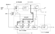
- the schematic schematic diagram of the 1st aspect of the ammonia manufacturing plant concerning this invention is shown.
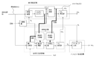
- the schematic schematic diagram of the 1st aspect of the ammonia manufacturing plant concerning this invention is shown.
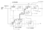
- the other schematic schematic diagram of the 1st aspect of the ammonia manufacturing plant concerning this invention is shown.
- the schematic diagram of the 2nd aspect of the ammonia manufacturing plant concerning this invention is shown.
- the other schematic schematic diagram of the 2nd aspect of the ammonia manufacturing plant concerning this invention is shown.
- the schematic diagram of the 2nd aspect of the ammonia manufacturing plant concerning this invention is shown.
- the positional relationship between the apparatus and the equipment may be expressed as “upstream” and “downstream” with reference to the flowing direction of a fluid such as gas.
- carbon monoxide may be expressed as CO, carbon dioxide as CO 2 , and hydrogen as H 2 .
- FIG. 1 shows the schematic schematic diagram of the 1st aspect of the ammonia manufacturing plant concerning this embodiment.
- the aspect of the ammonia production plant according to the present invention is as follows.
- An ammonia production plant for producing ammonia from carbon-based raw materials An ammonia synthesis facility for synthesizing ammonia, a synthesis gas generation facility for generating a synthesis gas for ammonia synthesis from the carbon-based raw material, and a power generation facility for obtaining power.
- the synthesis gas generation facility is a facility for generating synthesis gas containing H 2 as a main component from a carbon-based raw material.
- the synthesis gas generation facility includes an exhaust heat recovery unit that recovers exhaust heat generated when generating synthesis gas.
- the exhaust heat recovered by the exhaust heat recovery unit is used to heat the recycle gas described later.
- the synthesis gas may contain CO, CO 2, and methane generated during the synthesis gas generation in addition to H 2 .
- Natural gas or coal (coal gas obtained by gasifying coal) is used as the carbon-based raw material.
- These raw materials include hydrocarbons having 1 or more carbon atoms.
- the synthesis gas generation facility When natural gas is used as the carbon-based raw material, the synthesis gas generation facility reforms natural gas to generate synthesis gas.
- the exhaust heat recovery unit recovers exhaust heat after the natural gas reforming reaction.
- the synthesis gas generation facility gasifies the coal to generate synthesis gas.
- the exhaust heat recovery unit recovers exhaust heat after the coal gasification reaction. In the gasification reaction of coal, oxygen and coal are reacted to generate synthesis gas.
- the synthesis gas generation facility of the present embodiment is configured to collect CO 2 gas contained in the synthesis gas.
- the synthesis gas production facility has a shift reaction unit that reacts carbon monoxide and steam in the synthesis gas obtained by the reforming reaction (shift reaction) to produce hydrogen and carbon dioxide. It may be.
- the synthesis gas generation facility may include a CO 2 recovery unit that recovers carbon dioxide obtained by the shift reaction (see FIG. 2 described later in detail).
- Exhaust heat after natural gas reforming is recovered by the exhaust heat recovery unit. Moreover, since the shift reaction is an exothermic reaction, this exothermic heat can also be recovered by the exhaust heat recovery unit.
- Hydrogen obtained by separating the CO 2 gas from the gas obtained by the shift reaction is sent to an ammonia synthesis facility by a compressor or the like as a raw material gas for the ammonia synthesis reaction.
- ammonia is synthesized by reacting hydrogen generated in the synthesis gas generation facility with nitrogen supplied from a separation device (see FIG. 2) described later.
- the power generation facility includes a combustion device that burns oxygen and fuel, and a gas turbine that generates power by driving combustion gas containing CO 2 gas obtained by the combustion device as power, and CO 2 gas discharged from the gas turbine is supplied to the combustion device as a recycle gas.
- the power generation facility of the present embodiment further includes a boosting unit for supplying CO 2 gas discharged from the gas turbine as the recycle gas to the combustion device.
- the power obtained from the power generation equipment is used at least as power for the ammonia synthesis equipment.
- the ammonia synthesis facility is a facility that requires a large amount of power
- the power obtained from the power generation facility is a source gas compressor that boosts the ammonia source gas (mixed gas of nitrogen and hydrogen) to the reaction pressure. It is also used as a power source for refrigeration compressors and the like that produce cold heat for cooling and separating synthesized ammonia.
- the power obtained by the power generation facility may be used as power for an air compressor installed in the separation device (deep cold separation device) shown in FIG.
- the power obtained by the power generation facility may be used in the synthesis gas generation facility, or may be used in the power generation facility.
- the combustion apparatus is an apparatus for combusting oxygen and natural gas and obtaining combustion gas containing CO 2 gas and water vapor by the combustion reaction.
- the combustion apparatus of this embodiment burns high-purity oxygen and natural gas.
- the CO 2 concentration in the obtained combustion gas is higher (CO 2 partial pressure in the combustion gas is higher) than when natural gas is burned by supplying air. . Therefore, energy required for CO 2 gas recovery can be reduced, and the CO 2 gas recovery rate can be increased.
- the gas turbine is driven by the combustion gas containing the CO 2 gas obtained by the combustion device as power.
- the gas turbine is supplied with a combustion gas of 15 bar to 300 bar and 800 ° C to 1300 ° C, and the pressure and temperature of the combustion gas that has finished the work for generating power is reduced to about 1 bar to 80 bar and about 500 ° C to 700 ° C. In this state, it is discharged from the gas turbine.
- the boosting unit boosts the CO 2 gas discharged from the gas turbine.
- the CO 2 boosted by the booster is sent to the combustion device as a recycled gas. Since the state of CO 2 boosted by the booster is determined by the operating pressure and operating temperature, CO 2 at the outlet of the booster is a gas, liquid, or gas-liquid mixture.
- the CO 2 that is boosted and sent to the combustion device is heated by the exhaust heat recovered by the exhaust heat recovery unit. This heating makes it possible to further improve the thermal efficiency of the combustion apparatus, and to build a process that can produce ammonia with much less energy than conventional methods.
- the boosting unit boosts the CO 2 gas recovered in the syngas generation facility with CO 2 gas discharged from the gas turbine. That is, it is also possible to join the CO 2 gas separated and recovered from the synthesis gas generation facility to the pressure raising unit and send it as a recycled gas to the combustion apparatus.
- the booster can be shared to boost the CO 2 gas separated and recovered from the synthesis gas generation facility, it is not necessary to separately provide the booster facility in the synthesis gas generation facility, and the facility cost can be reduced. Can do.
- the synthesis gas generation facility is equipped with a CO 2 recovery unit such as a device for separating acidic gas by a chemical absorption method using a solvent such as amine, a PSA (pressure swing adsorption) method, a cryogenic separation device (details will be described later). It is also possible to separate and recover CO 2 .
- a CO 2 recovery unit such as a device for separating acidic gas by a chemical absorption method using a solvent such as amine, a PSA (pressure swing adsorption) method, a cryogenic separation device (details will be described later). It is also possible to separate and recover CO 2 .
- the water vapor in the exhaust gas of the gas turbine is separated and recovered as water before increasing the pressure of CO 2 (H 2 O discharged from the pressure increasing portion in FIG. 1).
- CO 2 corresponding to the amount of carbon of the carbon-based raw material introduced into the combustion apparatus is discharged out of the power generation facility from the material balance in the facility.
- the discharged CO 2 may be recovered and utilized through techniques such as CCS (Carbon Dioxide Capture and Storage) and EOR (Enhanced Oil Recovery).
- ammonia production facility By using the exhaust heat in the synthesis gas generation facility and ammonia synthesis facility (hereinafter sometimes collectively referred to as ammonia production facility) in the power generation facility, the efficiency of the power generation facility can be further improved. Energy savings can be improved through effective use of exhaust heat.
- FIG. 2 shows a more preferable embodiment of the first embodiment of FIG.
- the synthesis gas generation facility includes a CO 2 recovery unit that recovers CO 2 gas contained in the synthesis gas.
- the ammonia production plant of this embodiment further includes a separation device that separates air into oxygen and nitrogen.
- the separation device is not particularly limited as long as it can separate oxygen and nitrogen, but the PSA method, deep cold separation, or the like can be used without any particular limitation.
- a cryogenic separation type separation apparatus is preferable. In the cryogenic separation, air is cooled to a level of ⁇ 180 ° C., liquefied and distilled to separate nitrogen and oxygen, and the power obtained from the power generation equipment is used as the power of the compressor that produces cold.
- the separated nitrogen is used in an ammonia synthesis facility.
- the synthesis gas generation facility includes a first reforming unit that reforms the carbon-based material and a second reforming unit that reforms the carbon-based material that has not been reformed by the first reforming unit. Further, the synthesis gas generation facility may include a shift reaction unit that converts CO generated by the reforming reaction in the first reforming unit and the second reforming unit into CO 2 .
- the shift reaction part is the same as that shown in the embodiment shown in FIG.
- the first reforming unit is configured to reform the carbon-based raw material by a steam reforming reaction.
- the second reforming unit is configured to reform the carbon-based material using a partial oxidation reaction.
- the separation device is configured to supply oxygen to the combustion device and the second reforming unit.
- the first reforming unit mainly reforms hydrocarbons having 2 or more carbon atoms (a component heavier than methane, hereinafter may be expressed as a C2 plus component).
- the second reformer mainly reforms methane.
- the first reforming unit is provided upstream of the second reforming unit.
- the carbon-based raw material modified with the C2 plus component is supplied to the second reforming unit, and was not reformed in the first reforming unit.
- the carbon-based raw material (that is, mainly methane) can be reformed in the second reforming section. That is, since the heavy component contained in the carbon-based raw material to be reformed in the second reforming section is reduced, the generation of unburned carbon and the like are suppressed, and the catalyst and apparatus for the second reforming section that are operated at high temperatures It is possible to extend the life of the battery.
- the steam reforming performed in the first reforming part is an endothermic reaction, and the C2 plus component is reformed to obtain CO and H 2 .
- the partial oxidation reaction performed in the second reforming part is an exothermic reaction, and methane is partially oxidized.
- heat necessary for the steam reforming reaction which is an endothermic reaction, is supplied, and CO and H 2 as synthesis gases are obtained.
- a mixed gas of CO, CO 2 , H 2 and unreacted methane is obtained from the second reforming section.
- the exhaust heat exhausted from the second reforming unit is recovered by the exhaust heat recovery unit, a part of which is used for heating the first reforming unit, and the recycle gas sent to the combustion device is heated. To do.
- High temperature exhaust heat of 800 ° C to 1100 ° C is generated at the outlet of the second reforming section. Conventionally, this heat has been used to make steam at 300 ° C. to 400 ° C., and high temperature exhaust heat has not been effectively utilized.
- the high-temperature exhaust heat is used for heating the recycle gas sent to the combustion apparatus and heating the first reforming section, and it is possible to further improve the thermal efficiency.
- An autothermal reformer may be used for such a second reforming section, and the plant can be enlarged.
- the autothermal reformer self-heats by the reaction heat generated by the partial oxidation reaction with oxygen and eliminates the need for external heat supply, and an adiabatic reactor is used.
- steam reforming simultaneously proceeds by this self-heating.
- the exhaust heat recovery unit includes a high-temperature heat exchanger that recovers high-temperature exhaust heat having a predetermined temperature, and a low-temperature heat exchanger that recovers low-temperature exhaust heat that is lower than the high-temperature exhaust heat. .
- the high temperature heat exchanger recovers high temperature exhaust heat generated in the second reforming unit, and the low temperature heat exchanger recovers low temperature exhaust heat generated in the shift reaction unit.
- the high temperature heat exchanger recovers heat from 500 ° C to 1100 ° C, and the low temperature heat exchanger recovers heat generated by the shift reaction, which is lower than the high temperature exhaust heat.
- Part of the exhaust heat recovered by the exhaust heat recovery unit is used to heat the recycled gas whose pressure has been increased by the pressure increase unit. If high-temperature exhaust heat is used for heating the recycle gas in this way, heat can be used efficiently and high-temperature CO 2 gas can be supplied to the combustion device, thereby reducing the amount of fuel supplied to the combustion device. Can do. Therefore, the power generation facility can be operated with higher efficiency than when the recycle gas is not heated by the high-temperature exhaust heat.
- a part of the low temperature exhaust heat recovered by the low temperature heat exchanger is used to generate at least steam necessary for the steam reforming reaction.
- a part of the low-temperature exhaust heat may be used to raise the temperature of water, or may be used as heat for vaporizing water.
- the oxygen obtained by the separation device is supplied to the combustion device of this embodiment.
- the combustion device burns the oxygen and natural gas. That is, the combustion apparatus of this embodiment burns substantially pure oxygen and natural gas.
- the oxygen supplied to the combustion apparatus may be of high purity.
- a high-concentration oxygen gas having an oxygen concentration of 95% or more may be used for combustion.
- the exhaust heat recovered by the exhaust heat recovery unit is CO 2 gas exhausted from the gas turbine, and CO 2 before being supplied to the booster unit.
- the recycle gas may be heated by the heated CO 2 gas used for gas heating.
- the power generation device performs heat exchange between the gas turbine and the boosting unit between the CO 2 gas discharged from the gas turbine and the recycle gas (CO 2 gas). You may provide the heat exchange part.
- the high-temperature exhaust heat recovered by the exhaust heat recovery unit heats the CO 2 gas exhausted from the gas turbine, and the heat exchange unit heats the recycled gas with the heated CO 2 gas. May be.
- indirectly heating the recycled gas by heating the CO 2 gas discharged from the gas turbine can ease the design conditions of the high-temperature heat exchanger and reduce the cost of the high-temperature heat exchanger. can do. That is, when the recycle gas is directly heated at the outlet of the heat exchange section (when the recycle gas is heated at the position of the broken line and A in FIG. 3), the high temperature heat is generated based on the high pressure (after pressure increase) recycle gas. Since the exchanger is designed, the design pressure of the high-temperature heat exchanger is increased. On the other hand, by heating the CO 2 gas at a relatively low pressure position, a high-temperature heat exchanger can be designed based on the low-pressure recycle gas, and the equipment cost can be reduced.
- FIG. 4 shows a schematic diagram of another aspect of the ammonia production plant according to the present invention.
- the same name is attached
- subjected and description is not repeated.
- the synthesis gas generation facility has an exhaust heat recovery unit that recovers exhaust heat generated during synthesis gas generation
- the power generation facility includes a combustion device that burns oxygen and fuel, a water vapor generation device that generates water vapor by exhaust heat in the combustion gas containing CO 2 gas obtained by the combustion device, and the water vapor generation device.
- a steam turbine that generates power by driving generated steam as power, and is configured to supply CO 2 gas discharged from the steam generator to the combustion device as a recycle gas,
- the power obtained in the power generation facility is used at least as power for the ammonia synthesis facility, and the exhaust heat recovered in the exhaust heat recovery unit is used for generation of water vapor in the steam generator.
- the power generation facility has a gas turbine that is driven by combustion gas containing CO 2 gas obtained by combustion, and the steam generator generates steam by exhaust heat of the gas turbine. To do.
- FIG. 4 utilizes the concept of gas turbine combined cycle power generation.
- exhaust heat in the exhaust gas discharged from the gas turbine is used as a heat source of the steam generator, and steam is generated using the exhaust heat recovered by the exhaust heat recovery unit as a heat source.
- the gas containing CO 2 gas and water vapor discharged from the water vapor generating device is pressurized by the pressure increasing unit and supplied to the combustion device as a recycle gas.
- the high-temperature exhaust gas (about 700 ° C.) from the gas turbine is heated by the heat recovered by the exhaust heat recovery unit, and the heated exhaust gas is supplied to, for example, an exhaust heat recovery boiler as a steam generator. .
- the heated exhaust gas is used as a heat source for generating water vapor, and the steam turbine is driven using the generated water vapor.
- the power generation device includes a gas turbine
- the power generation device may not include the gas turbine.
- the power generation device includes a combustion device and a water vapor generation device, and supplies CO 2 gas discharged from the water vapor generation device to the combustion device as a recycle gas. It may be configured. Even with this configuration, it is possible to provide a highly energy-saving ammonia production plant capable of reducing CO 2 gas emission as a whole and recovering CO 2 gas with high efficiency.
- FIG. 6 shows a more preferable aspect of the second aspect shown in FIG.
- the power generation facility has a pressure feeding device that transfers condensed water that has been condensed after being used to drive the steam turbine, together with water from the outside, to the steam generation device.
- the condensed water becomes steam again in the steam generator and is used to drive the steam turbine. In this way, the condensed water circulates between the water vapor generating device and the pressure feeding device.
- the synthesis gas generation facility is configured to recover the CO 2 gas contained in the synthesis gas, and the pressurization unit pressurizes the CO 2 gas discharged from the gas turbine and the recovered CO 2 gas. It becomes.
- the synthesis gas generation facility includes a first reforming unit for reforming the carbon-based material and a second reforming of the carbon-based material that has not been modified by the first reforming unit.
- the second reforming unit is configured to reform the carbon-based material using a partial oxidation reaction, and the separation device supplies oxygen to the combustion device and the second reforming unit. It is configured.
- Such a 1st modification part and a 2nd modification part are the same as that of the aspect of FIG. 2, You may use an autothermal reformer for a 2nd modification part.
- the exhaust heat recovery unit includes a high-temperature heat exchanger that recovers high-temperature exhaust heat having a predetermined temperature, and a low-temperature heat exchanger that recovers low-temperature exhaust heat that is lower than the high-temperature exhaust heat.
- the high temperature heat exchanger is configured to recover high temperature exhaust heat generated in the second reforming unit, and the low temperature heat exchanger is configured to recover low temperature exhaust heat generated in the shift reaction unit.
- a part of the high temperature exhaust heat recovered by the high temperature heat exchanger is used for heating the first reforming unit.
- the high-temperature exhaust heat recovered by the high-temperature heat exchanger and the low-temperature exhaust heat recovered by the low-temperature heat exchanger are used for generating steam in the steam generator.
- the high-temperature exhaust heat recovered by the high-temperature heat exchanger is used to vaporize water in the steam generator and generate steam.
- the low-temperature exhaust heat recovered by the low-temperature heat exchanger is used for heating the condensed water obtained after driving the steam turbine.
- the low temperature heat exchanger is installed downstream of the pumping device. When exhaust heat is used in this way, heat can be used efficiently.
- the synthesis gas from which carbon dioxide, which is a catalyst poison for ammonia synthesis, has been removed is sent to a nitrogen scrubber (not shown) as necessary, and an inert gas component (also referred to as an inert component) is removed by cryogenic separation. It is sent to the ammonia synthesis facility.
- the synthesis gas from which carbon dioxide has been removed is sent to a methanation device, and carbon monoxide and carbon dioxide remaining in a trace amount in the synthesis gas are converted into methane that becomes inactive to the ammonia synthesis catalyst by the methanation reaction. After being converted, it may be sent to an ammonia synthesis facility.
- Hydrogen and nitrogen obtained in the synthesis gas generation facility and the separation device are pressurized to a synthesis pressure (15 to 80 bar) of ammonia synthesis by a compressor (not shown), and an ammonia synthesis reaction start temperature (about 400 ° C. to 500 ° C.) ) To be used for ammonia synthesis reaction.
- the obtained ammonia is separated and recovered as an ammonia product through known separation equipment such as cooling separation using a refrigeration compressor.
- Ammonia synthesis can be performed by a known ammonia synthesis process.
- the ammonia synthesis process for example, the Harbor Bosch method using an iron-based catalyst can be adopted.
- the synthesis reaction is performed under a high pressure of 200 bar or more, which is also called a high pressure method.
- a method of synthesizing ammonia under a low pressure condition using a ruthenium catalyst (low pressure method) can also be adopted.
- a catalyst in which a ruthenium catalyst is supported on a support can be used.
- the carrier for supporting ruthenium alumina or a rare earth oxide can be used as a catalyst carrier.
- an ammonia synthesis method has been proposed in which hydrogen (ions) supplied via a proton exchange membrane reacts with nitrogen.
- an autothermal reformer is employed in the second reforming section, and high-purity oxygen obtained by the separation device is supplied to the combustion device.
- the ammonia production method is an ammonia production method for producing ammonia from a carbon-based raw material, An ammonia synthesis process for synthesizing ammonia; A synthesis gas generation step for generating synthesis gas for ammonia synthesis from the carbon-based raw material; A power generation process for obtaining power,
- the synthesis gas generation step includes a step of recovering exhaust heat generated at the time of synthesis gas generation,
- the power generation step includes a step of burning oxygen and fuel in a combustion device, a step of generating power by a gas turbine that is driven by a combustion gas containing CO 2 gas obtained by the combustion, and the gas turbine.
- the power obtained in the power generation step is used as power for synthesizing ammonia
- the exhaust heat recovered in the synthesis gas generation step is used to heat the recycle gas.
- the ammonia production method is an ammonia production method for producing ammonia from a carbon-based raw material, An ammonia synthesis process for synthesizing ammonia; A synthesis gas generation step for generating synthesis gas for ammonia synthesis from the carbon-based raw material; A power generation process for obtaining power,
- the synthesis gas generation step includes a step of recovering exhaust heat generated at the time of synthesis gas generation,
- the power generation step includes a step of burning oxygen and fuel with a combustion device, a step of generating water vapor with a steam generator by exhaust heat in the combustion gas containing CO 2 gas obtained by the combustion, and the water vapor
- the power obtained in the power generation step is used as power for synthesizing ammonia,
- the exhaust heat recovered in the power generation step is used as power for synthesizing
- ammonia production method includes a step of generating power by a gas turbine that drives the combustion gas obtained by the combustion device as power, and the exhaust heat of the gas turbine is used for generation of water vapor. May be.
- high-purity oxygen and fuel are combusted by a combustion device, and by adopting an efficient power generation facility, consumption of raw materials for ammonia synthesis is suppressed, and CO 2 gas is reduced. It is possible to construct a highly energy-saving ammonia production plant that can reduce the emission and collect the discharged CO 2 gas with high efficiency.
- an autothermal reformer to build a process that does not discharge flue exhaust gas, the loss of expensive solvent used in the CO 2 recovery device for recovering CO 2 in flue exhaust gas or from the solvent Large energy required for CO 2 separation can be eliminated.
- the energy consumption of the plant can be reduced by about 20% even when a separation device that separates air into oxygen and nitrogen is used.
- the separation device can be shared by the synthesis gas generation facility and the power generation facility. Therefore, equipment costs can be suppressed. Further, the separation device may supply nitrogen to the ammonia synthesis facility, and in this case, the separation device can be shared by three facilities of the synthesis gas generation facility, the power generation facility, and the ammonia synthesis facility.
- the combustion device for startup that can only be used for conventional startup It is possible to start up an ammonia plant without CO 2 emission by using the exhaust heat of the power generation facility without having the power.
- the gas turbine is driven by starting up the combustion apparatus, and power in the ammonia production plant can be obtained. Further, steam necessary for the reforming reaction or the like can be generated by the exhaust heat of the gas turbine.
- ammonia production plant of the present invention is not limited to the above embodiment, and it is needless to say that various modifications can be made without departing from the scope of the present invention.
- the first reforming section or the second reforming section is extracted from the steam turbine, and the extracted steam is used as the steam used in the steam reforming reaction. May be supplied. Further, when heat exhausted from the ammonia synthesis facility (heat generation during ammonia synthesis) is recovered, water vapor is generated, and the water vapor is used as a water vapor for the steam reforming reaction. You may use for a modification part.
- the ammonia production plant may be equipped with a desulfurization device that removes sulfur contained in the carbon-based raw material.
- the desulfurization apparatus may be provided in the raw material supply line shown in FIG. 1, and the carbon-based raw material after desulfurization may be supplied to the synthesis gas generation facility and the power generation facility.
- wastewater treatment costs from the power generation facility can be reduced by sharing the desulfurization apparatus in the synthesis gas generation facility and the power generation facility.
- exhaust heat generated mainly in the synthesis gas generation facility is used in the power generation facility
- the present invention is not limited to this.
- Exhaust heat generated in the ammonia synthesis facility may be used in the power generation facility to improve energy saving.
- the outlet gas of the ammonia synthesis reactor provided in the ammonia synthesis facility may be used for water vapor generation by the water vapor generator, or may be used for heating the recycle gas. Good.
- the synthesis gas generation facility replaces the first reforming unit and the second reforming unit to gasify coal.
- the exhaust heat recovery unit may recover the exhaust heat generated when the synthesis gas is generated in the gasification furnace.
- the synthesis gas obtained in the gasification furnace is supplied as fuel to the combustion apparatus.
- the synthesis gas obtained in the gasification furnace may be sent to the shift reaction unit after heavy metals are removed, and the synthesis gas obtained in the shift reaction unit may be supplied as fuel to the combustion apparatus.
- the oxygen obtained by the separation device may be supplied to a gasification furnace and used for coal gasification.
Landscapes
- Chemical & Material Sciences (AREA)
- Chemical Kinetics & Catalysis (AREA)
- Organic Chemistry (AREA)
- Inorganic Chemistry (AREA)
- Engineering & Computer Science (AREA)
- Health & Medical Sciences (AREA)
- Analytical Chemistry (AREA)
- Combustion & Propulsion (AREA)
- General Health & Medical Sciences (AREA)
- Biomedical Technology (AREA)
- Environmental & Geological Engineering (AREA)
- General Chemical & Material Sciences (AREA)
- Oil, Petroleum & Natural Gas (AREA)
- Engine Equipment That Uses Special Cycles (AREA)
- Hydrogen, Water And Hydrids (AREA)
- Carbon And Carbon Compounds (AREA)
- Fertilizers (AREA)
Abstract
Description
炭素系原料からアンモニアを製造するためのアンモニア製造プラントであって、
アンモニアを合成するためのアンモニア合成設備と、前記炭素系原料からアンモニア合成用の合成ガスを生成するための合成ガス生成設備と、動力を得るための動力発生設備と、を備え、
前記合成ガス生成設備は、合成ガス生成時に発生する排熱を回収する排熱回収部を有し、
前記動力発生設備は、酸素と燃料とを燃焼させる燃焼装置と、当該燃焼装置で得られたCO2ガスを含む燃焼ガスを動力として駆動することにより動力を発生するガスタービンと、を有し、且つ前記ガスタービンから排出されたCO2ガスをリサイクルガスとして前記燃焼装置に供給するように構成され、
前記動力発生設備で得られた動力は、少なくとも前記アンモニア合成設備の動力として使用され、
前記排熱回収部で回収された排熱は、前記リサイクルガスを加熱するために使用されることを特徴とする。
炭素系原料からアンモニアを製造するためのアンモニア製造プラントであって、
アンモニアを合成するためのアンモニア合成設備と、前記炭素系原料からアンモニア合成用の合成ガスを生成するための合成ガス生成設備と、動力を得るための動力発生設備と、を備え、
前記合成ガス生成設備は、合成ガス生成時に発生する排熱を回収する排熱回収部を有し、
前記動力発生設備は、酸素と燃料とを燃焼させる燃焼装置と、当該燃焼装置で得られたCO2ガスを含む燃焼ガス中の排熱により水蒸気を発生する水蒸気発生装置と、当該水蒸気発生装置で発生した水蒸気を動力として駆動することにより動力を発生するスチームタービンと、を有し、且つ前記水蒸気発生装置から排出されたCO2ガスをリサイクルガスとして前記燃焼装置に供給するように構成され、
前記動力発生設備で得られた動力は、少なくとも前記アンモニア合成設備の動力として使用され、
前記排熱回収部で回収された排熱は、前記水蒸気発生装置における水蒸気の発生に使用されることを特徴とする。
図1は、本実施形態にかかるアンモニア製造プラントの第1の態様の概略模式図を示す。
炭素系原料からアンモニアを製造するためのアンモニア製造プラントであって、
アンモニアを合成するためのアンモニア合成設備と、前記炭素系原料からアンモニア合成用の合成ガスを生成するための合成ガス生成設備と、動力を得るための動力発生設備と、を備える。
図4は、本発明にかかるアンモニア製造プラントの別の一態様の概略模式図を示す。尚、第1の態様と共通する構成については同じ名称を付し、説明は繰り返さない。
前記合成ガス生成設備は、合成ガス生成時に発生する排熱を回収する排熱回収部を有し、
前記動力発生設備は、酸素と燃料とを燃焼させる燃焼装置と、当該燃焼装置で得られたCO2ガスを含む燃焼ガス中の排熱により水蒸気を発生する水蒸気発生装置と、当該水蒸気発生装置で発生した水蒸気を動力として駆動することにより動力を発生するスチームタービンと、を有し、且つ前記水蒸気発生装置から排出されたCO2ガスをリサイクルガスとして前記燃焼装置に供給するように構成され、
前記動力発生設備で得られた動力は、少なくとも前記アンモニア合成設備の動力として使用され、前記排熱回収部で回収された排熱は、前記水蒸気発生装置における水蒸気の発生に使用される。
アンモニアを合成するアンモニア合成工程と、
前記炭素系原料からアンモニア合成用の合成ガスを生成する合成ガス生成工程と、
動力を得るため動力発生工程と、を備え、
前記合成ガス生成工程は、合成ガス生成時に発生する排熱を回収する工程を有し、
前記動力発生工程は、酸素と燃料とを燃焼装置で燃焼させる工程と、当該燃焼により得られたCO2ガスを含む燃焼ガスを動力として駆動するガスタービンにより動力を発生させる工程と、前記ガスタービンから排出されたCO2ガスをリサイクルガスとして前記燃焼装置に供給する工程と、を有し、
少なくとも前記アンモニア合成工程では、前記動力発生工程で得られた動力がアンモニアを合成するための動力として使用され、
前記動力発生工程では、前記合成ガス生成工程で回収された排熱が、前記リサイクルガスを加熱するために使用される。
アンモニアを合成するアンモニア合成工程と、
前記炭素系原料からアンモニア合成用の合成ガスを生成する合成ガス生成工程と、
動力を得るため動力発生工程と、を備え、
前記合成ガス生成工程は、合成ガス生成時に発生する排熱を回収する工程を有し、
前記動力発生工程は、酸素と燃料とを燃焼装置で燃焼させる工程と、当該燃焼により得られたCO2ガスを含む燃焼ガス中の排熱により水蒸気発生装置で水蒸気を発生させる工程と、当該水蒸気を動力として駆動するスチームタービンにより動力を発生させる工程と、前記水蒸気発生装置から排出されたCO2ガスをリサイクルガスとして前記燃焼装置に供給する工程と、を有し、
少なくとも前記アンモニア合成工程では、前記動力発生工程で得られた動力がアンモニアを合成するための動力として使用され、
前記動力発生工程では、前記合成ガス生成工程で回収された排熱が、前記スチームタービンを駆動するための水蒸気の発生に使用される。
Claims (12)
- 炭素系原料からアンモニアを製造するためのアンモニア製造プラントであって、
アンモニアを合成するためのアンモニア合成設備と、前記炭素系原料からアンモニア合成用の合成ガスを生成するための合成ガス生成設備と、動力を得るための動力発生設備と、を備え、
前記合成ガス生成設備は、合成ガス生成時に発生する排熱を回収する排熱回収部を有し、
前記動力発生設備は、酸素と燃料とを燃焼させる燃焼装置と、当該燃焼装置で得られたCO2ガスを含む燃焼ガスを動力として駆動することにより動力を発生するガスタービンと、を有し、且つ前記ガスタービンから排出されたCO2ガスをリサイクルガスとして前記燃焼装置に供給するように構成され、
前記動力発生設備で得られた動力は、少なくとも前記アンモニア合成設備の動力として使用され、
前記排熱回収部で回収された排熱は、前記リサイクルガスを加熱するために使用されることを特徴とするアンモニア製造プラント。 - 炭素系原料からアンモニアを製造するためのアンモニア製造プラントであって、
アンモニアを合成するためのアンモニア合成設備と、前記炭素系原料からアンモニア合成用の合成ガスを生成するための合成ガス生成設備と、動力を得るための動力発生設備と、を備え、
前記合成ガス生成設備は、合成ガス生成時に発生する排熱を回収する排熱回収部を有し、
前記動力発生設備は、酸素と燃料とを燃焼させる燃焼装置と、当該燃焼装置で得られたCO2ガスを含む燃焼ガス中の排熱により水蒸気を発生する水蒸気発生装置と、当該水蒸気発生装置で発生した水蒸気を動力として駆動することにより動力を発生するスチームタービンと、を有し、且つ前記水蒸気発生装置から排出されたCO2ガスをリサイクルガスとして前記燃焼装置に供給するように構成され、
前記動力発生設備で得られた動力は、少なくとも前記アンモニア合成設備の動力として使用され、
前記排熱回収部で回収された排熱は、前記水蒸気発生装置における水蒸気の発生に使用されることを特徴とするアンモニア製造プラント。 - 前記動力発生設備は、前記燃焼ガスを動力として駆動することにより動力を発生するガスタービンを有し、前記水蒸気発生装置は、前記ガスタービンの排熱により水蒸気を発生する請求項2に記載のアンモニア製造プラント。
- 前記動力発生設備は、前記ガスタービンから排出されたCO2ガスを前記リサイクルガスとして前記燃焼装置に供給するための昇圧部を備え、
前記合成ガス生成設備は、合成ガス中に含まれるCO2ガスを回収するように構成され、
前記昇圧部は、前記ガスタービンから排出されたCO2ガスと前記回収されたCO2ガスとを昇圧する請求項1または3に記載のアンモニア製造プラント。 - 空気を酸素と窒素とに分離する分離装置をさらに備え、
前記合成ガス生成設備は、前記炭素系原料を改質する第1改質部と前記第1改質部で改質されなかった炭素系原料を改質する第2改質部と、を備え、
前記第2改質部は、部分酸化反応を利用して前記炭素系原料を改質するように構成され、
前記分離装置は、前記燃焼装置及び前記第2改質部に酸素を供給するように構成されている請求項1~3のいずれかに記載のアンモニア製造プラント。 - 前記排熱回収部は、所定の温度を有する高温排熱を回収する高温熱交換器と、前記高温排熱よりも低温の低温排熱を回収する低温熱交換器と、を備え、
前記合成ガス生成設備は、前記炭素系原料を改質する第1改質部と前記第1改質部で改質されなかった炭素系原料を改質する第2改質部と、前記第1改質部及び前記第2改質部における改質反応により生成したCOをCO2に転換するシフト反応部と、を備え、
前記高温熱交換器は、前記第2改質部で発生した高温排熱を回収し、前記低温熱交換器は、前記シフト反応部で発生した低温排熱を回収する請求項1~5のいずれかに記載のアンモニア製造プラント。 - 前記第1改質部は、水蒸気改質反応により前記炭素系原料を改質するように構成され、
前記高温熱交換器で回収された高温排熱の一部は、前記第1改質部における改質反応のために使用される請求項6に記載のアンモニア製造プラント。 - 前記第1改質部は、水蒸気改質反応により前記炭素系原料を改質するように構成され、
前記低温熱交換器で回収された低温排熱の一部は、少なくとも前記水蒸気改質反応で必要な水蒸気を発生させるために使用されることを特徴とする請求項6または7に記載のアンモニア製造プラント。 - 前記動力発生設備は、前記ガスタービンから排出されたCO2ガスを前記リサイクルガスとして前記燃焼装置に供給するための昇圧部を備え、
前記排熱回収部で回収された排熱は、前記ガスタービンから排出されたCO2ガスであって前記昇圧部に供給される前のCO2ガスの加熱に使用され、
前記加熱されたCO2ガスにより前記リサイクルガスが加熱される請求項1に記載のアンモニア製造プラント。 - 炭素系原料が、天然ガスまたは石炭である請求項1~9のいずれかに記載のアンモニア製造プラント。
- 炭素系原料からアンモニアを製造するアンモニアの製造方法であって、
アンモニアを合成するアンモニア合成工程と、
前記炭素系原料からアンモニア合成用の合成ガスを生成する合成ガス生成工程と、
動力を得るため動力発生工程と、を備え、
前記合成ガス生成工程は、合成ガス生成時に発生する排熱を回収する工程を有し、
前記動力発生工程は、酸素と燃料とを燃焼装置で燃焼させる工程と、当該燃焼により得られたCO2ガスを含む燃焼ガスを動力として駆動するガスタービンにより動力を発生させる工程と、前記ガスタービンから排出されたCO2ガスをリサイクルガスとして前記燃焼装置に供給する工程と、を有し、
少なくとも前記アンモニア合成工程では、前記動力発生工程で得られた動力がアンモニアを合成するための動力として使用され、
前記動力発生工程では、前記合成ガス生成工程で回収された排熱が、前記リサイクルガスを加熱するために使用されることを特徴とするアンモニアの製造方法。 - 炭素系原料からアンモニアを製造するアンモニアの製造方法であって、
アンモニアを合成するアンモニア合成工程と、
前記炭素系原料からアンモニア合成用の合成ガスを生成する合成ガス生成工程と、
動力を得るため動力発生工程と、を備え、
前記合成ガス生成工程は、合成ガス生成時に発生する排熱を回収する工程を有し、
前記動力発生工程は、酸素と燃料とを燃焼装置で燃焼させる工程と、当該燃焼により得られたCO2ガスを含む燃焼ガス中の排熱により水蒸気発生装置で水蒸気を発生させる工程と、当該水蒸気を動力として駆動するスチームタービンにより動力を発生させる工程と、前記水蒸気発生装置から排出されたCO2ガスをリサイクルガスとして前記燃焼装置に供給する工程と、を有し、
少なくとも前記アンモニア合成工程では、前記動力発生工程で得られた動力がアンモニアを合成するための動力として使用され、
前記動力発生工程では、前記合成ガス生成工程で回収された排熱が、前記スチームタービンを駆動するための水蒸気の発生に使用されることを特徴とするアンモニアの製造方法。
Priority Applications (5)
| Application Number | Priority Date | Filing Date | Title |
|---|---|---|---|
| PCT/JP2018/018384 WO2019215925A1 (ja) | 2018-05-11 | 2018-05-11 | アンモニア製造プラントおよびアンモニアの製造方法 |
| AU2018423019A AU2018423019B2 (en) | 2018-05-11 | 2018-05-11 | Ammonia production plant and ammonia production method |
| US16/762,605 US11021373B2 (en) | 2018-05-11 | 2018-05-11 | Ammonia production plant and ammonia production method |
| JP2019524477A JP6664033B1 (ja) | 2018-05-11 | 2018-05-11 | アンモニア製造プラントおよびアンモニアの製造方法 |
| SA520420465A SA520420465B1 (ar) | 2018-05-11 | 2020-11-03 | وحدة صناعية وطريقة لإنتاج الأمونيا |
Applications Claiming Priority (1)
| Application Number | Priority Date | Filing Date | Title |
|---|---|---|---|
| PCT/JP2018/018384 WO2019215925A1 (ja) | 2018-05-11 | 2018-05-11 | アンモニア製造プラントおよびアンモニアの製造方法 |
Publications (1)
| Publication Number | Publication Date |
|---|---|
| WO2019215925A1 true WO2019215925A1 (ja) | 2019-11-14 |
Family
ID=68467905
Family Applications (1)
| Application Number | Title | Priority Date | Filing Date |
|---|---|---|---|
| PCT/JP2018/018384 Ceased WO2019215925A1 (ja) | 2018-05-11 | 2018-05-11 | アンモニア製造プラントおよびアンモニアの製造方法 |
Country Status (5)
| Country | Link |
|---|---|
| US (1) | US11021373B2 (ja) |
| JP (1) | JP6664033B1 (ja) |
| AU (1) | AU2018423019B2 (ja) |
| SA (1) | SA520420465B1 (ja) |
| WO (1) | WO2019215925A1 (ja) |
Families Citing this family (2)
| Publication number | Priority date | Publication date | Assignee | Title |
|---|---|---|---|---|
| CN115092884B (zh) * | 2022-07-14 | 2023-04-18 | 招商局海洋装备研究院有限公司 | 一种自加热氨分解制氢装置及其制氢方法 |
| WO2024220025A1 (en) * | 2023-04-20 | 2024-10-24 | Agency For Science, Technology And Research | Catalytic process using ammonia as hydrogen source for carbon dioxide conversion |
Citations (5)
| Publication number | Priority date | Publication date | Assignee | Title |
|---|---|---|---|---|
| JP2008535768A (ja) * | 2005-04-11 | 2008-09-04 | イーストマン ケミカル カンパニー | ガス化及びアンモニア製造の一体化 |
| JP2008222480A (ja) * | 2007-03-12 | 2008-09-25 | Ihi Corp | アンモニア合成方法 |
| WO2014042042A1 (ja) * | 2012-09-12 | 2014-03-20 | 三菱重工業株式会社 | 改質装置及び改質方法、改質装置を備えた化成品の製造装置及び化成品の製造方法 |
| JP2014185583A (ja) * | 2013-03-22 | 2014-10-02 | Central Research Institute Of Electric Power Industry | Nh3併産型の発電プラント |
| WO2017149718A1 (ja) * | 2016-03-03 | 2017-09-08 | 日揮株式会社 | アンモニアの製造方法 |
Family Cites Families (4)
| Publication number | Priority date | Publication date | Assignee | Title |
|---|---|---|---|---|
| DE3320228A1 (de) * | 1983-06-03 | 1984-12-06 | Kraftwerk Union AG, 4330 Mülheim | Kraftwerk mit einer integrierten kohlevergasungsanlage |
| US7909898B2 (en) * | 2006-02-01 | 2011-03-22 | Air Products And Chemicals, Inc. | Method of treating a gaseous mixture comprising hydrogen and carbon dioxide |
| US10106430B2 (en) * | 2013-12-30 | 2018-10-23 | Saudi Arabian Oil Company | Oxycombustion systems and methods with thermally integrated ammonia synthesis |
| EP2957544A1 (en) | 2014-06-18 | 2015-12-23 | Casale SA | Process for production of ammonia and derivatives, in particular urea |
-
2018
- 2018-05-11 US US16/762,605 patent/US11021373B2/en active Active
- 2018-05-11 WO PCT/JP2018/018384 patent/WO2019215925A1/ja not_active Ceased
- 2018-05-11 AU AU2018423019A patent/AU2018423019B2/en not_active Ceased
- 2018-05-11 JP JP2019524477A patent/JP6664033B1/ja active Active
-
2020
- 2020-11-03 SA SA520420465A patent/SA520420465B1/ar unknown
Patent Citations (5)
| Publication number | Priority date | Publication date | Assignee | Title |
|---|---|---|---|---|
| JP2008535768A (ja) * | 2005-04-11 | 2008-09-04 | イーストマン ケミカル カンパニー | ガス化及びアンモニア製造の一体化 |
| JP2008222480A (ja) * | 2007-03-12 | 2008-09-25 | Ihi Corp | アンモニア合成方法 |
| WO2014042042A1 (ja) * | 2012-09-12 | 2014-03-20 | 三菱重工業株式会社 | 改質装置及び改質方法、改質装置を備えた化成品の製造装置及び化成品の製造方法 |
| JP2014185583A (ja) * | 2013-03-22 | 2014-10-02 | Central Research Institute Of Electric Power Industry | Nh3併産型の発電プラント |
| WO2017149718A1 (ja) * | 2016-03-03 | 2017-09-08 | 日揮株式会社 | アンモニアの製造方法 |
Also Published As
| Publication number | Publication date |
|---|---|
| US20210053834A1 (en) | 2021-02-25 |
| SA520420465B1 (ar) | 2023-10-29 |
| AU2018423019B2 (en) | 2022-07-28 |
| US11021373B2 (en) | 2021-06-01 |
| AU2018423019A1 (en) | 2020-11-19 |
| JP6664033B1 (ja) | 2020-03-13 |
| JPWO2019215925A1 (ja) | 2020-05-28 |
Similar Documents
| Publication | Publication Date | Title |
|---|---|---|
| JP7795524B2 (ja) | 一酸化炭素を含むガス流を製造するためのプロセス | |
| US7634915B2 (en) | Systems and methods for power generation and hydrogen production with carbon dioxide isolation | |
| JP7113394B2 (ja) | 水素の一貫生産を伴う電力生産のためのシステム及び方法 | |
| CN101981162B (zh) | 低排放发电和烃采收系统及方法 | |
| CA2773458C (en) | Integration of reforming/water splitting and electrochemical systems for power generation with integrated carbon capture | |
| Medrano et al. | Thermodynamic analysis of a membrane-assisted chemical looping reforming reactor concept for combined H2 production and CO2 capture | |
| CA2795887A1 (en) | Decarbonized fuel generation | |
| AU2013326478B2 (en) | Process for producing hydrogen and generating power | |
| US8278362B2 (en) | Method of combining existing chemical processes to produce hydrocarbon fuels | |
| JP6664033B1 (ja) | アンモニア製造プラントおよびアンモニアの製造方法 | |
| JP4981439B2 (ja) | 固体燃料ガス化ガス利用プラント | |
| CN101663376B (zh) | 联合进行发电和产生烃 | |
| JP2005336076A (ja) | 液体燃料製造プラント | |
| JP2006022687A (ja) | 合成ガス製造兼発電装置 | |
| WO2023217804A1 (en) | Process and plant for producing synthesis gas | |
| JP2002122030A (ja) | 電力と水素の併産設備 |
Legal Events
| Date | Code | Title | Description |
|---|---|---|---|
| ENP | Entry into the national phase |
Ref document number: 2019524477 Country of ref document: JP Kind code of ref document: A |
|
| 121 | Ep: the epo has been informed by wipo that ep was designated in this application |
Ref document number: 18917632 Country of ref document: EP Kind code of ref document: A1 |
|
| NENP | Non-entry into the national phase |
Ref country code: DE |
|
| ENP | Entry into the national phase |
Ref document number: 2018423019 Country of ref document: AU Date of ref document: 20180511 Kind code of ref document: A |
|
| 122 | Ep: pct application non-entry in european phase |
Ref document number: 18917632 Country of ref document: EP Kind code of ref document: A1 |