WO2019212048A1 - Open/close detection sensor - Google Patents
Open/close detection sensor Download PDFInfo
- Publication number
- WO2019212048A1 WO2019212048A1 PCT/JP2019/018000 JP2019018000W WO2019212048A1 WO 2019212048 A1 WO2019212048 A1 WO 2019212048A1 JP 2019018000 W JP2019018000 W JP 2019018000W WO 2019212048 A1 WO2019212048 A1 WO 2019212048A1
- Authority
- WO
- WIPO (PCT)
- Prior art keywords
- state
- open
- base
- detection sensor
- moving
- Prior art date
Links
- 238000001514 detection method Methods 0.000 title claims abstract description 104
- 239000013307 optical fiber Substances 0.000 claims abstract description 59
- 230000008859 change Effects 0.000 description 45
- 238000010586 diagram Methods 0.000 description 37
- 238000001228 spectrum Methods 0.000 description 23
- 230000002093 peripheral effect Effects 0.000 description 10
- 238000000034 method Methods 0.000 description 7
- 230000008569 process Effects 0.000 description 6
- 238000012937 correction Methods 0.000 description 4
- 230000007704 transition Effects 0.000 description 4
- 238000003466 welding Methods 0.000 description 4
- 239000000463 material Substances 0.000 description 3
- 229910001220 stainless steel Inorganic materials 0.000 description 3
- 239000010935 stainless steel Substances 0.000 description 3
- 230000006835 compression Effects 0.000 description 2
- 238000007906 compression Methods 0.000 description 2
- 230000008602 contraction Effects 0.000 description 2
- 230000007246 mechanism Effects 0.000 description 2
- 239000011347 resin Substances 0.000 description 2
- 229920005989 resin Polymers 0.000 description 2
- 230000035945 sensitivity Effects 0.000 description 2
- 239000000853 adhesive Substances 0.000 description 1
- 230000001070 adhesive effect Effects 0.000 description 1
- 239000003795 chemical substances by application Substances 0.000 description 1
- 238000007796 conventional method Methods 0.000 description 1
- 230000007423 decrease Effects 0.000 description 1
- 230000000694 effects Effects 0.000 description 1
- 239000002184 metal Substances 0.000 description 1
- 238000012986 modification Methods 0.000 description 1
- 230000004048 modification Effects 0.000 description 1
- 230000003287 optical effect Effects 0.000 description 1
- 238000012545 processing Methods 0.000 description 1
- 230000000717 retained effect Effects 0.000 description 1
- 238000005728 strengthening Methods 0.000 description 1
- 230000002123 temporal effect Effects 0.000 description 1
Images


Classifications
-
- G—PHYSICS
- G02—OPTICS
- G02B—OPTICAL ELEMENTS, SYSTEMS OR APPARATUS
- G02B6/00—Light guides; Structural details of arrangements comprising light guides and other optical elements, e.g. couplings
- G02B6/02—Optical fibres with cladding with or without a coating
- G02B6/02057—Optical fibres with cladding with or without a coating comprising gratings
- G02B6/02076—Refractive index modulation gratings, e.g. Bragg gratings
-
- G—PHYSICS
- G01—MEASURING; TESTING
- G01D—MEASURING NOT SPECIALLY ADAPTED FOR A SPECIFIC VARIABLE; ARRANGEMENTS FOR MEASURING TWO OR MORE VARIABLES NOT COVERED IN A SINGLE OTHER SUBCLASS; TARIFF METERING APPARATUS; MEASURING OR TESTING NOT OTHERWISE PROVIDED FOR
- G01D5/00—Mechanical means for transferring the output of a sensing member; Means for converting the output of a sensing member to another variable where the form or nature of the sensing member does not constrain the means for converting; Transducers not specially adapted for a specific variable
- G01D5/26—Mechanical means for transferring the output of a sensing member; Means for converting the output of a sensing member to another variable where the form or nature of the sensing member does not constrain the means for converting; Transducers not specially adapted for a specific variable characterised by optical transfer means, i.e. using infrared, visible, or ultraviolet light
- G01D5/32—Mechanical means for transferring the output of a sensing member; Means for converting the output of a sensing member to another variable where the form or nature of the sensing member does not constrain the means for converting; Transducers not specially adapted for a specific variable characterised by optical transfer means, i.e. using infrared, visible, or ultraviolet light with attenuation or whole or partial obturation of beams of light
- G01D5/34—Mechanical means for transferring the output of a sensing member; Means for converting the output of a sensing member to another variable where the form or nature of the sensing member does not constrain the means for converting; Transducers not specially adapted for a specific variable characterised by optical transfer means, i.e. using infrared, visible, or ultraviolet light with attenuation or whole or partial obturation of beams of light the beams of light being detected by photocells
- G01D5/353—Mechanical means for transferring the output of a sensing member; Means for converting the output of a sensing member to another variable where the form or nature of the sensing member does not constrain the means for converting; Transducers not specially adapted for a specific variable characterised by optical transfer means, i.e. using infrared, visible, or ultraviolet light with attenuation or whole or partial obturation of beams of light the beams of light being detected by photocells influencing the transmission properties of an optical fibre
- G01D5/35306—Mechanical means for transferring the output of a sensing member; Means for converting the output of a sensing member to another variable where the form or nature of the sensing member does not constrain the means for converting; Transducers not specially adapted for a specific variable characterised by optical transfer means, i.e. using infrared, visible, or ultraviolet light with attenuation or whole or partial obturation of beams of light the beams of light being detected by photocells influencing the transmission properties of an optical fibre using an interferometer arrangement
- G01D5/35309—Mechanical means for transferring the output of a sensing member; Means for converting the output of a sensing member to another variable where the form or nature of the sensing member does not constrain the means for converting; Transducers not specially adapted for a specific variable characterised by optical transfer means, i.e. using infrared, visible, or ultraviolet light with attenuation or whole or partial obturation of beams of light the beams of light being detected by photocells influencing the transmission properties of an optical fibre using an interferometer arrangement using multiple waves interferometer
- G01D5/35316—Mechanical means for transferring the output of a sensing member; Means for converting the output of a sensing member to another variable where the form or nature of the sensing member does not constrain the means for converting; Transducers not specially adapted for a specific variable characterised by optical transfer means, i.e. using infrared, visible, or ultraviolet light with attenuation or whole or partial obturation of beams of light the beams of light being detected by photocells influencing the transmission properties of an optical fibre using an interferometer arrangement using multiple waves interferometer using a Bragg gratings
-
- G—PHYSICS
- G01—MEASURING; TESTING
- G01L—MEASURING FORCE, STRESS, TORQUE, WORK, MECHANICAL POWER, MECHANICAL EFFICIENCY, OR FLUID PRESSURE
- G01L1/00—Measuring force or stress, in general
- G01L1/24—Measuring force or stress, in general by measuring variations of optical properties of material when it is stressed, e.g. by photoelastic stress analysis using infrared, visible light, ultraviolet
- G01L1/242—Measuring force or stress, in general by measuring variations of optical properties of material when it is stressed, e.g. by photoelastic stress analysis using infrared, visible light, ultraviolet the material being an optical fibre
- G01L1/246—Measuring force or stress, in general by measuring variations of optical properties of material when it is stressed, e.g. by photoelastic stress analysis using infrared, visible light, ultraviolet the material being an optical fibre using integrated gratings, e.g. Bragg gratings
-
- G—PHYSICS
- G01—MEASURING; TESTING
- G01V—GEOPHYSICS; GRAVITATIONAL MEASUREMENTS; DETECTING MASSES OR OBJECTS; TAGS
- G01V8/00—Prospecting or detecting by optical means
- G01V8/10—Detecting, e.g. by using light barriers
- G01V8/12—Detecting, e.g. by using light barriers using one transmitter and one receiver
- G01V8/16—Detecting, e.g. by using light barriers using one transmitter and one receiver using optical fibres
-
- H—ELECTRICITY
- H03—ELECTRONIC CIRCUITRY
- H03K—PULSE TECHNIQUE
- H03K17/00—Electronic switching or gating, i.e. not by contact-making and –breaking
- H03K17/94—Electronic switching or gating, i.e. not by contact-making and –breaking characterised by the way in which the control signals are generated
- H03K17/965—Switches controlled by moving an element forming part of the switch
- H03K17/968—Switches controlled by moving an element forming part of the switch using opto-electronic devices
-
- G—PHYSICS
- G02—OPTICS
- G02B—OPTICAL ELEMENTS, SYSTEMS OR APPARATUS
- G02B6/00—Light guides; Structural details of arrangements comprising light guides and other optical elements, e.g. couplings
- G02B6/10—Light guides; Structural details of arrangements comprising light guides and other optical elements, e.g. couplings of the optical waveguide type
- G02B6/12—Light guides; Structural details of arrangements comprising light guides and other optical elements, e.g. couplings of the optical waveguide type of the integrated circuit kind
- G02B2006/12133—Functions
- G02B2006/12138—Sensor
-
- G—PHYSICS
- G02—OPTICS
- G02B—OPTICAL ELEMENTS, SYSTEMS OR APPARATUS
- G02B6/00—Light guides; Structural details of arrangements comprising light guides and other optical elements, e.g. couplings
- G02B6/02—Optical fibres with cladding with or without a coating
- G02B6/02057—Optical fibres with cladding with or without a coating comprising gratings
- G02B6/02076—Refractive index modulation gratings, e.g. Bragg gratings
- G02B6/02195—Refractive index modulation gratings, e.g. Bragg gratings characterised by means for tuning the grating
- G02B6/022—Refractive index modulation gratings, e.g. Bragg gratings characterised by means for tuning the grating using mechanical stress, e.g. tuning by compression or elongation, special geometrical shapes such as "dog-bone" or taper
-
- G—PHYSICS
- G02—OPTICS
- G02B—OPTICAL ELEMENTS, SYSTEMS OR APPARATUS
- G02B6/00—Light guides; Structural details of arrangements comprising light guides and other optical elements, e.g. couplings
- G02B6/02—Optical fibres with cladding with or without a coating
- G02B6/02057—Optical fibres with cladding with or without a coating comprising gratings
- G02B6/02076—Refractive index modulation gratings, e.g. Bragg gratings
- G02B6/02209—Mounting means, e.g. adhesives, casings
Landscapes
- Physics & Mathematics (AREA)
- General Physics & Mathematics (AREA)
- Optics & Photonics (AREA)
- Life Sciences & Earth Sciences (AREA)
- General Life Sciences & Earth Sciences (AREA)
- Geophysics (AREA)
- Optical Transform (AREA)
- Length Measuring Devices By Optical Means (AREA)
- Geophysics And Detection Of Objects (AREA)
Abstract
This open/close detection sensor comprises a fixed base, a moving base, an optical fiber, and a moving member. The moving base is arranged so as to be movable relative to the fixed base. The optical fiber comprises a FBG in which the Bragg wavelength fluctuates in accordance with the gap between the fixed base and the moving base. The moving member moves between a first position corresponding to either the open state or the closed state for a detection target and a second position corresponding to the other state, in accordance with the opening/closing of the detection target. The moving member also comprises a locking section. The locking section: abuts the moving base and moves the moving base in conjunction with the moving member, between the second position and a third position positioned between the first position and the second position; and moves the moving base in a direction away from the fixed base.
Description
本発明は、マンホール蓋や扉等の開閉状態を検知するセンサに関し、特に、FBG(Fiber Bragg Grating)を備える光ファイバを利用する開閉検知センサに関する。
The present invention relates to a sensor for detecting an open / closed state of a manhole cover, a door, or the like, and more particularly, to an open / close detection sensor using an optical fiber having FBG (Fiber Bragg Grating).
従来、セキュリティー強化の観点で、マンホール蓋や扉等に、開閉状態を検知するためセンサが設置されている。この種の開閉検知センサとして、近年、光ファイバセンサが使用されている(例えば、特許文献1から特許文献4等。)。光ファイバセンサを利用した開閉検知センサでは、複数の検知対象物のそれぞれに配置されたセンサを直列に接続することで、複数の検知対象物の開閉状態を同時に監視することができる。また、各センサへの給電が不要であるため、各センサに給電用の配線を配置する必要もない。そのため、都市部に設けられた下水管路のマンホール蓋や、データセンタにおいてサーバを格納するサーバラックの扉等、多数の検知対象物の開閉状態を比較的容易に同時監視することができる。このような開閉検知センサでは、蓋や扉の開閉状態の変更に応じて光ファイバが変形するように構成され、光ファイバ中を伝送される光の反射状態や散乱状態が光ファイバの変形に応じて変化することを利用して検知対象物の開閉状態を検知している。
Conventionally, from the viewpoint of strengthening security, sensors have been installed on manhole covers and doors to detect the open / closed state. In recent years, optical fiber sensors have been used as this type of opening / closing detection sensor (for example, Patent Document 1 to Patent Document 4). In an open / close detection sensor using an optical fiber sensor, the open / closed states of a plurality of detection objects can be simultaneously monitored by connecting in series the sensors arranged in each of the plurality of detection objects. In addition, since power supply to each sensor is unnecessary, it is not necessary to arrange power supply wiring for each sensor. For this reason, it is possible to relatively easily and simultaneously monitor the open / closed states of a large number of detection objects such as manhole covers of sewer pipes provided in urban areas and server rack doors storing servers in the data center. In such an open / close detection sensor, the optical fiber is configured to be deformed in accordance with a change in the open / closed state of the lid or the door, and the reflection state or scattering state of light transmitted through the optical fiber depends on the deformation of the optical fiber. The open / closed state of the object to be detected is detected using the change of the detected object.
公知のように、光ファイバは、周囲温度が変動した場合、膨張や収縮によって変形したり、屈折率が変動したりする。したがって、光ファイバ中を伝送される光の反射状態や散乱状態、すなわち、センサ出力値も周囲温度に応じて変動することになる。温度変動に起因するセンサ出力値の変動は、光ファイバの変形等が温度変動に伴って発生するため比較的長い時間を要することになる。そのため、従来は、センサ出力値の時間変化率があらかじめ指定された閾値より小さいものは、温度変動に起因するセンサ出力値の変動であると識別して、検知対象物の開閉状態は変化していないと判定していた。
As is well known, when the ambient temperature fluctuates, the optical fiber deforms due to expansion and contraction, and the refractive index fluctuates. Therefore, the reflection state and scattering state of light transmitted through the optical fiber, that is, the sensor output value also varies depending on the ambient temperature. The fluctuation of the sensor output value caused by the temperature fluctuation takes a relatively long time because the deformation of the optical fiber or the like occurs with the temperature fluctuation. For this reason, conventionally, when the rate of change of the sensor output value with time is smaller than the threshold value specified in advance, it is identified that the sensor output value fluctuates due to temperature fluctuations, and the open / close state of the detection object has changed. It was judged that there was not.
しかしながら、検知対象物の開閉状態が極めてゆっくりと変更された場合、センサ出力値もゆっくりと変動することになる。すなわち、センサ出力値の時間変化率が上述の閾値よりも小さくなる状態で検知対象物の開閉状態が変更された場合、当該開閉状態の変更は温度変動に起因するセンサ出力値の変動と判定され、検知できないことになる。
However, if the open / close state of the detection target is changed very slowly, the sensor output value also varies slowly. That is, when the open / close state of the detection target is changed in a state where the rate of time change of the sensor output value is smaller than the above-described threshold, the change in the open / close state is determined as a change in the sensor output value due to a temperature change. It will not be detected.
また、検知対象物の開閉状態の変更頻度が極めて少ない場合、光ファイバの形状が長期間維持される形状に固定される可能性もある。例えば、マンホール蓋の開閉を検知する場合において、閉状態にあるときに光ファイバに外力が付与され、開状態にあるときに当該外力が開放される構成であるとする。この場合、マンホール蓋は閉状態で長期間維持されるため光ファイバは外力により変形した状態で長期間維持される。このような状況下においてマンホール蓋が開状態になり、光ファイバに付与された外力が開放されたとしても、閉状態が極めて長期間にわたって継続していると、光ファイバの形状が閉状態の形状に固定化される結果、光ファイバが元の形状に戻り難くなることがある。このような状況が発生すると、開閉状態の変動を正確に検知することができず、検知感度が低下してしまう。
Also, when the frequency of changing the open / close state of the detection target is extremely low, the shape of the optical fiber may be fixed to a shape that can be maintained for a long time. For example, in the case of detecting the opening / closing of a manhole cover, it is assumed that an external force is applied to the optical fiber when it is in a closed state and the external force is released when it is in an open state. In this case, since the manhole cover is maintained in a closed state for a long period of time, the optical fiber is maintained in a state of being deformed by an external force for a long period of time. Under such circumstances, even if the manhole cover is opened and the external force applied to the optical fiber is released, if the closed state continues for a very long period of time, the shape of the optical fiber is closed. As a result, the optical fiber may be difficult to return to its original shape. When such a situation occurs, the fluctuation of the open / close state cannot be accurately detected, and the detection sensitivity is lowered.
本発明は、このような従来技術の課題を鑑みてなされたものであって、検知対象物の開閉状態が極めてゆっくりと変更された場合や開閉状態の変更頻度が極めて少ない状況下でも、当該開閉状態の変更を確実に検知することができる開閉検知センサを提供することを目的とする。
The present invention has been made in view of such a problem of the prior art, and the open / close state of the object to be detected is changed even when the open / close state of the object to be detected is changed very slowly or under a very low change frequency of the open / close state. An object of the present invention is to provide an open / close detection sensor capable of reliably detecting a change in state.
上述の目的を達成するために、本発明は以下の技術的手段を採用している。まず、本発明は、光ファイバを利用した開閉検知センサを前提としている。そして、本発明に係る開閉検知センサは、第1のベース部材、第2のベース部材、光ファイバ、及び移動部材を備える。第2のベース部材は、第1のベース部材に対して移動可能に配置される。光ファイバは、第1のベース部材と第2のベース部材との間隔に応じてブラッグ波長が変動するFBG(Fiber Bragg Grating)部を備える。移動部材は、検知対象物の開閉に伴って、検知対象物の開状態及び閉状態の一方の状態に対応する第1の位置と、他方の状態に対応する第2の位置とにわたって移動する。また、当該移動部材は係止部を備える。係止部は、第1の位置と第2の位置の間に位置する第3の位置と第2の位置との間において第2のベース部材と当接して第2のベース部材を移動部材とともに移動させ、第2のベース部材を第1のベース部材から離れる方向に移動させる。
In order to achieve the above object, the present invention employs the following technical means. First, the present invention is premised on an open / close detection sensor using an optical fiber. The open / close detection sensor according to the present invention includes a first base member, a second base member, an optical fiber, and a moving member. The second base member is movably disposed with respect to the first base member. The optical fiber includes an FBG (Fiber Bragg Grating) portion whose Bragg wavelength varies according to the distance between the first base member and the second base member. The moving member moves over a first position corresponding to one of the open state and the closed state of the detection target and a second position corresponding to the other state as the detection target is opened and closed. The moving member includes a locking portion. The locking portion abuts on the second base member between the third position and the second position, which are located between the first position and the second position, and moves the second base member together with the moving member. The second base member is moved in a direction away from the first base member.
本発明の開閉検知センサによれば、検知対象物の開閉に伴って移動部材が移動し、当該移動部材が特定位置(第3の位置)に到達したときに、瞬間的にFBG部に張力が付与される、あるいは、FBG部に付与されていた張力が瞬間的に開放される。そのため、検知対象物の開閉状態が極めてゆっくりと変更された場合でも、当該開閉状態の変更をブラッグ波長のシフトとして確実に検知することができる。
According to the open / close detection sensor of the present invention, when the moving member moves in accordance with opening / closing of the detection target and the moving member reaches the specific position (third position), the FBG portion is instantaneously tensioned. The applied tension or the tension applied to the FBG portion is instantaneously released. Therefore, even when the open / close state of the detection target is changed very slowly, the change in the open / close state can be reliably detected as a shift of the Bragg wavelength.
この開閉検知センサにおいて、例えば、光ファイバのFBG部を含む部分が直線状に配置され、第2のベース部材及び移動部材が当該直線状に配置された光ファイバの軸方向に沿って移動する構成を採用することができる。
In this open / close detection sensor, for example, the portion including the FBG portion of the optical fiber is arranged linearly, and the second base member and the moving member move along the axial direction of the optical fiber arranged in a straight line. Can be adopted.
また、移動部材に対して、第1の位置から第2の位置へ向かう方向に付勢力を付与する付勢部材をさらに備える構成を採用することもできる。さらに、移動部材が検知対象物に当接する当接部を備える構成を採用することもできる。以上の構成において、移動部材が中空部材により構成され、第1のベース部材、第2のベース部材及び光ファイバが、移動部材の内部に配置される構成を採用することもできる。加えて、第1のベース部材と第2のベース部材とが接触している状況下において、FBG部に光ファイバの軸方向に沿う圧縮力が付与された状態で、光ファイバが第1のベース部材と第2のベース部材とに固定される構成を採用することもできる。なお、第1のベース部材上に温度補償用のFBG部をさらに備える構成を採用することもできる。
It is also possible to adopt a configuration further including a biasing member that applies a biasing force to the moving member in a direction from the first position toward the second position. Furthermore, a configuration in which the moving member includes an abutting portion that abuts on the detection target can be employed. In the above configuration, it is also possible to adopt a configuration in which the moving member is constituted by a hollow member, and the first base member, the second base member, and the optical fiber are arranged inside the moving member. In addition, in a situation where the first base member and the second base member are in contact with each other, the optical fiber is in the state where the compression force along the axial direction of the optical fiber is applied to the FBG portion. The structure fixed to a member and a 2nd base member is also employable. It is also possible to employ a configuration in which an FBG portion for temperature compensation is further provided on the first base member.
本発明によれば、検知対象物の開閉状態が極めてゆっくりと変更された場合や開閉状態の変更頻度が極めて少ない状況下でも、当該開閉状態の変更を確実に検知することができる。
According to the present invention, it is possible to reliably detect the change in the open / close state even when the open / close state of the object to be detected is changed very slowly or even in a situation where the change frequency of the open / close state is extremely low.
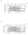
以下、本発明の実施形態について、図面を参照しながらより詳細に説明する。図1(a)及び図1(b)は、本実施形態における開閉検知センサの構造の一例を示す図である。図1(a)は、本実施形態における開閉検知センサ1の外観を示す概略図である。図1(b)は、本実施形態における開閉検知センサ1の内部構造を示す概略図である。
Hereinafter, embodiments of the present invention will be described in more detail with reference to the drawings. FIG. 1A and FIG. 1B are diagrams showing an example of the structure of the open / close detection sensor in the present embodiment. FIG. 1A is a schematic diagram showing an appearance of the open / close detection sensor 1 in the present embodiment. FIG. 1B is a schematic diagram showing the internal structure of the open / close detection sensor 1 in the present embodiment.
図1(a)及び図1(b)に示すように、開閉検知センサ1は、一方側の開放端が閉塞された円筒状のケース10内にセンサ部20と移動部材30とが配置された構造を有する。ケース10の閉塞側端部10a(以下、基端部10aという。)には断面L字状の取付具11が固定されている。開閉検知センサ1は、取付具11が備える貫通溝11aに挿入されるネジ等により所望の対象物に固定される。この例では、貫通溝11aはケース10の軸方向に沿って設けられており、開閉検知センサ1を対象物に固定する際に、当該軸方向に沿う位置の調整が可能になっている。なお、特に限定されないが、本実施形態では、ケース10の外径は30mm程度であり、軸方向の全長は80mm程度である。
As shown in FIGS. 1 (a) and 1 (b), the open / close detection sensor 1 has a sensor unit 20 and a moving member 30 arranged in a cylindrical case 10 with an open end on one side closed. It has a structure. An attachment 11 having an L-shaped cross section is fixed to the closing side end portion 10a (hereinafter referred to as a base end portion 10a) of the case 10. The open / close detection sensor 1 is fixed to a desired object by a screw or the like inserted into the through groove 11a included in the fixture 11. In this example, the through groove 11a is provided along the axial direction of the case 10, and the position along the axial direction can be adjusted when the open / close detection sensor 1 is fixed to the object. Although not particularly limited, in this embodiment, the outer diameter of the case 10 is about 30 mm, and the total length in the axial direction is about 80 mm.
ケース10の先端部10bには、移動部材30が出入自在に配置されている。移動部材30は円筒状部材で構成されており、ケース10の先端部10bに対して出入する部分は、先端部10bの内径に整合する外径を有している。ケース10の外部に露出する側の移動部材30の開放端はゴム等の樹脂製の蓋部材で閉塞されており、当該蓋部材が検知対象物に当接する当接部30aを構成している。
The moving member 30 is disposed at the front end portion 10b of the case 10 so as to be freely accessible. The moving member 30 is formed of a cylindrical member, and a portion of the case 10 that enters and exits the tip portion 10b has an outer diameter that matches the inner diameter of the tip portion 10b. The open end of the moving member 30 on the side exposed to the outside of the case 10 is closed by a lid member made of resin such as rubber, and the lid member constitutes an abutting portion 30a that abuts against the object to be detected.
また、移動部材30は、基端部10aから先端部10bに向かう方向に、ケース10の軸に沿って付勢されている。後述の図3(b)、図4(b)に示すように、本実施形態の移動部材30では、ケース10の内側に収容される部分の外径は、ケース10の先端部10bを出入りする部分の外径より小さくなっている。また、ケース10において、移動部材30の外径が小さくなっている部分と対向する部位の内径は、先端部10bの内径よりも大きくなっている。このような構成により、ケース10の内部では、移動部材30の外周面とケース10の内周面との間にリング状の空間が形成されている。本実施形態では、当該空間に、付勢部材として、ケース10の軸と同軸につる巻きバネ12が配置されている。つる巻きバネ12は、一方端がケース10の基端部10aに当接し、他方端が移動部材30の外周面に設けられた段差30bに当接している。
Further, the moving member 30 is urged along the axis of the case 10 in the direction from the base end portion 10a to the tip end portion 10b. As shown in FIGS. 3B and 4B to be described later, in the moving member 30 of the present embodiment, the outer diameter of the portion accommodated inside the case 10 enters and exits the front end portion 10b of the case 10. It is smaller than the outer diameter of the part. Moreover, in case 10, the internal diameter of the site | part which opposes the part where the outer diameter of the moving member 30 is small is larger than the internal diameter of the front-end | tip part 10b. With such a configuration, a ring-shaped space is formed between the outer peripheral surface of the moving member 30 and the inner peripheral surface of the case 10 inside the case 10. In the present embodiment, a spiral spring 12 that is coaxial with the axis of the case 10 is disposed as an urging member in the space. The helical spring 12 has one end in contact with the base end portion 10 a of the case 10 and the other end in contact with a step 30 b provided on the outer peripheral surface of the moving member 30.
例えば、検知対象物がマンホール蓋である場合、本実施形態の開閉検知センサ1は、閉状態にあるマンホール蓋の裏面(マンホール側の面)に対してケース10の軸が垂直となる状態で配置される。このとき、当接部30aはマンホール蓋裏面に接触しており、移動部材30はつる巻きバネ12による付勢力に抗してケース10の内部に押し込まれた状態にある。この場合、マンホール蓋が閉状態から開状態に変化すると、移動部材30がつる巻きバネ12の付勢力によりケース10の先端部10bから軸方向外側に突出する状態になる。開閉検知センサ1は、このような移動部材30の移動を検知することで検知対象物の開閉状態を検知する。なお、ケース10の軸方向に沿う移動部材30の長さは、移動部材30がケース10の内部に押し込まれた際に、ケース10の基端部10aと干渉することのない長さに設定される(図3(b)、図4(b)参照。)。
For example, when the detection target is a manhole cover, the open / close detection sensor 1 of the present embodiment is arranged in a state where the axis of the case 10 is perpendicular to the back surface (manhole side surface) of the manhole cover in the closed state. Is done. At this time, the contact portion 30 a is in contact with the back surface of the manhole cover, and the moving member 30 is pushed into the case 10 against the urging force of the helical spring 12. In this case, when the manhole cover changes from the closed state to the open state, the moving member 30 protrudes from the distal end portion 10b of the case 10 outward in the axial direction by the urging force of the helical spring 12. The open / close detection sensor 1 detects the open / closed state of the detection object by detecting the movement of the moving member 30. The length of the moving member 30 along the axial direction of the case 10 is set to a length that does not interfere with the base end portion 10a of the case 10 when the moving member 30 is pushed into the case 10. (See FIGS. 3B and 4B.)
図1(b)に示すように、センサ部20は、半円柱部21aの軸方向の両側に円柱部21b、21cが接続された形状のベース部材21、半円柱部21aに固定されたセンサベース24、及びセンサベース24に固定された光ファイバ25を備える。特に限定されないが、本実施形態では、ベース部材21は、ステンレスからなる円柱状部材の中央部分を切削加工等により半円柱状に加工することで形成されている。
As shown in FIG. 1B, the sensor unit 20 includes a base member 21 having a shape in which columnar portions 21b and 21c are connected to both sides in the axial direction of the half columnar portion 21a, and a sensor base fixed to the half columnar portion 21a. 24 and an optical fiber 25 fixed to the sensor base 24. Although not particularly limited, in this embodiment, the base member 21 is formed by processing a central portion of a cylindrical member made of stainless steel into a semi-cylindrical shape by cutting or the like.
ベース部材21は、ケース10に固定された固定ベース22(第1のベース部材)と、固定ベース22に対して移動可能な移動ベース23(第2のベース部材)を備える。本実施形態では、半円柱部21aにおいてケース10の軸に垂直な面に沿って、ベース部材21が、固定ベース22と移動ベース23とに分割されている。なお、本実施形態では、基端部10a側が固定ベース22であり、先端部10b側が移動ベース23である。また、固定ベース22の円柱部21bには、光ファイバ25をケース10の外部に引き出すための貫通孔29が設けられている。
The base member 21 includes a fixed base 22 (first base member) fixed to the case 10 and a movable base 23 (second base member) movable with respect to the fixed base 22. In the present embodiment, the base member 21 is divided into a fixed base 22 and a movable base 23 along a plane perpendicular to the axis of the case 10 in the semi-cylindrical portion 21a. In the present embodiment, the base end portion 10 a side is the fixed base 22, and the tip end portion 10 b side is the moving base 23. In addition, the cylindrical portion 21 b of the fixed base 22 is provided with a through hole 29 for drawing out the optical fiber 25 to the outside of the case 10.
図2(a)及び図2(b)は、本実施形態における開閉検知センサ1のセンサ部20の構造の一例を示す図である。図2(a)は、移動ベース23が固定ベース22と接触している状態を示す模式図である。また、図2(b)は、移動ベース23が固定ベース22と離間している状態を示す図である。なお、移動ベース23と固定ベース22との間の間隔は数十マイクロメートル程度であるが、図2(b)では、説明のために比較的大きな隙間を描いている。
FIG. 2A and FIG. 2B are diagrams showing an example of the structure of the sensor unit 20 of the open / close detection sensor 1 in the present embodiment. FIG. 2A is a schematic diagram showing a state in which the moving base 23 is in contact with the fixed base 22. FIG. 2B is a diagram showing a state in which the moving base 23 is separated from the fixed base 22. In addition, although the space | interval between the movement base 23 and the fixed base 22 is about several dozen micrometers, in FIG.2 (b), the comparatively big clearance gap is drawn for description.
図1(b)、図2(a)、図2(b)に示すように、センサベース24は、FBG(Fiber Bragg Grating)部26を備える光ファイバ25を固定支持する。センサベース24及び光ファイバ25は歪みゲージを構成しており、移動ベース23が固定ベース22に対して移動した場合に、その移動がブラッグ波長の変動として出力される。なお、ブラッグ波長の変動は、光ファイバ25の端部に接続された計測器を使用して従来の手法により取得することができる。
As shown in FIG. 1B, FIG. 2A, and FIG. 2B, the sensor base 24 fixedly supports an optical fiber 25 including an FBG (Fiber-Bragg-Grating) portion 26. The sensor base 24 and the optical fiber 25 constitute a strain gauge, and when the moving base 23 moves relative to the fixed base 22, the movement is output as a fluctuation of the Bragg wavelength. In addition, the fluctuation | variation of a Bragg wavelength can be acquired by the conventional method using the measuring device connected to the edge part of the optical fiber 25. FIG.
特に限定されないが、本実施形態では、センサベース24は、ケース10の軸方向に沿って対向して配置された2つの板状部31、32の幅方向の両端をメアンダ状の2つの弾性部33で連結した構造を有している。板状部31、32には、ケース10の軸方向に沿う溝部34が設けられており、当該溝部34に光ファイバ25が収容される。このとき、FBG部26は板状部31と板状部32との間に配置された状態で、FBG部26の両側の光ファイバ25が板状部31と板状部32とのそれぞれに接着剤等の固定材35により固定される。なお、センサベース24の材質は特に限定されない。例えば、樹脂であってもよく、金属であってもよい。ここでは、センサベース24はステンレスにより構成されている。
Although not particularly limited, in this embodiment, the sensor base 24 has two meander-shaped elastic portions at both ends in the width direction of the two plate- like portions 31 and 32 arranged to face each other along the axial direction of the case 10. 33 is connected. The plate- like portions 31 and 32 are provided with a groove portion 34 along the axial direction of the case 10, and the optical fiber 25 is accommodated in the groove portion 34. At this time, the optical fiber 25 on both sides of the FBG portion 26 is bonded to each of the plate-like portion 31 and the plate-like portion 32 in a state where the FBG portion 26 is disposed between the plate-like portion 31 and the plate-like portion 32. It is fixed by a fixing material 35 such as an agent. The material of the sensor base 24 is not particularly limited. For example, it may be a resin or a metal. Here, the sensor base 24 is made of stainless steel.
FBG部26はブラッグ波長により規定される波長の光を反射する。FBG部26は光ファイバ25のコアに所定の間隔で配置された複数の回折格子により構成され、ブラッグ波長は光ファイバの屈折率と回折格子の配置間隔との積に比例する。したがって、FBG部26が引っ張られ回折格子の間隔が拡がると、FBG部26により反射される光の波長は大きくなる。すなわち、FBG部26により反射される光の波長は、移動ベース23と固定ベース22との間隔に応じて変動し、移動ベース23が固定ベース22と接触している状態(図2(a)の状態)よりも、移動ベース23が固定ベース22と離間している状態(図2(b)の状態)の方が、FBG部26により反射される光の波長は大きくなる。なお、図中では、FBG部26を、便宜上、白黒の縞模様で表現している。
The FBG unit 26 reflects light having a wavelength defined by the Bragg wavelength. The FBG section 26 is composed of a plurality of diffraction gratings arranged at a predetermined interval in the core of the optical fiber 25, and the Bragg wavelength is proportional to the product of the refractive index of the optical fiber and the arrangement interval of the diffraction gratings. Therefore, when the FBG portion 26 is pulled and the interval between the diffraction gratings is increased, the wavelength of light reflected by the FBG portion 26 increases. That is, the wavelength of the light reflected by the FBG unit 26 varies according to the distance between the moving base 23 and the fixed base 22, and the moving base 23 is in contact with the fixed base 22 (in FIG. 2A). The wavelength of light reflected by the FBG unit 26 is larger in the state where the moving base 23 is separated from the fixed base 22 (the state in FIG. 2B) than in the state). In the figure, the FBG unit 26 is represented by a black and white striped pattern for convenience.
固定ベース22及び移動ベース23へのセンサベース24の固定には、接着剤やスポット溶接等、公知の任意の手法を採用することができる。本実施形態では、固定ベース22、移動ベース23、及びセンサベース24はステンレスで構成されているため、スポット溶接により、センサベース24を固定ベース22及び移動ベース23に固定している。図2(a)及び図2(b)に示すように、本実施形態では、板状部31、32は、スポット溶接用の凹部36を備えている。凹部36は、上述の溝部34の両側に配置されており、凹部36の底部がスポット溶接用の肉薄部を構成している。
For fixing the sensor base 24 to the fixed base 22 and the moving base 23, any known method such as an adhesive or spot welding can be employed. In this embodiment, since the fixed base 22, the moving base 23, and the sensor base 24 are made of stainless steel, the sensor base 24 is fixed to the fixed base 22 and the moving base 23 by spot welding. As shown in FIG. 2A and FIG. 2B, in the present embodiment, the plate- like portions 31 and 32 are provided with a concave portion 36 for spot welding. The recess 36 is disposed on both sides of the groove 34 described above, and the bottom of the recess 36 constitutes a thin portion for spot welding.
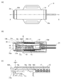
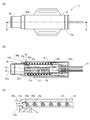
図3(a)から図3(c)及び図4(a)から図4(c)は、本実施形態における開閉検知センサ1の移動部材30と移動ベース23との関係を示す図である。図3(a)は、開閉検知センサ1の移動部材30がケース10内に押し込まれた状態を示す図である。図3(b)は、図3(a)に示すA-A線に沿う断面図である。図3(c)は、図3(b)に示す矢指部Pの近傍を拡大して示す図である。図4(a)は、開閉検知センサ1の移動部材30がケース10から突出した状態を示す図である。図4(b)は、図4(a)に示すB-B線に沿う断面図である。図4(c)は、図4(b)に示す矢指部Qの近傍を拡大して示す図である。なお、上述のように、移動ベース23と固定ベース22との間の間隔は数十マイクロメートルであるため、図2(b)とは異なり、図4(b)では隙間を描いていない。
3 (a) to 3 (c) and FIGS. 4 (a) to 4 (c) are diagrams showing the relationship between the moving member 30 and the moving base 23 of the open / close detection sensor 1 in this embodiment. FIG. 3A is a diagram illustrating a state where the moving member 30 of the open / close detection sensor 1 is pushed into the case 10. FIG. 3B is a cross-sectional view taken along line AA shown in FIG. FIG. 3C is an enlarged view showing the vicinity of the arrow finger part P shown in FIG. FIG. 4A is a diagram illustrating a state in which the moving member 30 of the open / close detection sensor 1 protrudes from the case 10. FIG. 4B is a cross-sectional view taken along line BB shown in FIG. FIG. 4C is an enlarged view showing the vicinity of the arrow finger portion Q shown in FIG. As described above, since the distance between the moving base 23 and the fixed base 22 is several tens of micrometers, unlike FIG. 2B, no gap is drawn in FIG. 4B.
本実施形態の開閉検知センサ1は、検知対象物の開状態と閉状態との一方が図3(a)から図3(c)に示す状態に対応し、他方が図4(a)から図4(c)に示す状態に対応する状態で設置される。検知対象物がマンホール蓋である上述の例の場合、図3(a)から図3(c)が閉状態に対応し、図4(a)から図4(c)が開状態に対応する。以下では、説明の便宜上、図3(a)から図3(c)に示す開閉検知センサ1の状態をオン状態といい、図4(a)から図4(c)に示す開閉検知センサ1の状態をオフ状態という。
In the open / close detection sensor 1 of the present embodiment, one of the open state and the closed state of the detection object corresponds to the state shown in FIGS. 3A to 3C, and the other is shown in FIG. It is installed in a state corresponding to the state shown in 4 (c). In the case of the above example in which the detection target is a manhole cover, FIGS. 3A to 3C correspond to the closed state, and FIGS. 4A to 4C correspond to the open state. Hereinafter, for convenience of explanation, the state of the opening / closing detection sensor 1 shown in FIGS. 3A to 3C is referred to as an ON state, and the opening / closing detection sensor 1 shown in FIGS. 4A to 4C is used. The state is called an off state.
図3(b)及び図4(b)に示すように、移動ベース23の円柱部21cの移動部材30側端部には周方向全体にわたってフランジ23aが設けられている。一方、移動部材30の内周面には、フランジ23aに係合する係止部30cが設けられている。本実施形態では、係止部30cは、周方向全体にわたって形成されている。また、移動部材30の外周面には、段差30bと当接部30aとの間に、抜け止めとして機能する段差30dが設けられている。本実施形態では、図3(b)及び図4(b)に示すように、段差30b及び段差30dは、移動部材30の外周面の周方向全体にわたって設けられた凸部の両端になっている。段差30dは、ケース10の内周面に形成された段差10cに当接することで、移動部材30がケース10の先端部10bから離脱するのを防止する。なお、特に限定されないが、本実施形態では、ケース10の軸方向において、段差30dと係止部30cとは同じ位置にある。また、段差10cは、ケース10の軸方向において、オン状態からオフ状態に移行する過程でフランジ23aと係止部30cとが初めて当接する位置よりも距離xだけ当接部30a側に位置している。
As shown in FIGS. 3B and 4B, a flange 23a is provided over the entire circumferential direction at the end of the cylindrical portion 21c of the moving base 23 on the moving member 30 side. On the other hand, a locking portion 30 c that engages with the flange 23 a is provided on the inner peripheral surface of the moving member 30. In this embodiment, the latching | locking part 30c is formed over the whole circumferential direction. Further, on the outer peripheral surface of the moving member 30, a step 30d that functions as a retaining member is provided between the step 30b and the contact portion 30a. In this embodiment, as shown in FIGS. 3B and 4B, the step 30 b and the step 30 d are both ends of the convex portion provided over the entire circumferential direction of the outer peripheral surface of the moving member 30. . The step 30 d contacts the step 10 c formed on the inner peripheral surface of the case 10, thereby preventing the moving member 30 from being detached from the tip portion 10 b of the case 10. Although not particularly limited, in this embodiment, the step 30d and the locking portion 30c are in the same position in the axial direction of the case 10. Further, the step 10c is located on the abutting portion 30a side in the axial direction of the case 10 by a distance x from the position where the flange 23a and the locking portion 30c abut for the first time in the process of shifting from the on state to the off state. Yes.
図3(b)に示すように、オン状態では、移動部材30がケース10内に押し込まれた状態にある。このとき、係止部30cは、フランジ23aに接触しない位置(第1の位置)にあり、移動ベース23は、例えば、センサベース24の弾性部33の弾性力により、固定ベース22と接触した状態に保持される。なお、本実施形態では、図3(b)に示すように、移動ベース23を固定ベース22に向けて付勢する付勢部材をさらに備える。図3(b)に示すように、移動ベース23の移動方向を規制する円柱状のレール41が固定ベース22に固定されており、移動ベース23は当該レール41に嵌合する貫通孔42を備える。当該貫通孔42の先端部は内径が広くなっており、レール41との間に隙間が設けられている。当該隙間に付勢部材であるつる巻きバネ43が配置される。また、レール41の移動ベース23側の端部には抜け止めのボルト44が螺合されており、つる巻きバネ43の一端が当該ボルト44に当接している。なお、つる巻きバネ43の付勢力は、つる巻きバネ12の付勢力よりも小さいため、移動部材30がオン状態からオフ状態に変化するときに、移動部材30の移動を妨害することもない。
As shown in FIG. 3B, the moving member 30 is pushed into the case 10 in the on state. At this time, the locking part 30c is in a position (first position) where it does not contact the flange 23a, and the moving base 23 is in contact with the fixed base 22 by the elastic force of the elastic part 33 of the sensor base 24, for example. Retained. In the present embodiment, as shown in FIG. 3B, a biasing member that biases the moving base 23 toward the fixed base 22 is further provided. As shown in FIG. 3B, a columnar rail 41 that regulates the moving direction of the moving base 23 is fixed to the fixed base 22, and the moving base 23 includes a through hole 42 that fits into the rail 41. . The front end portion of the through hole 42 has a large inner diameter, and a gap is provided between the front end portion and the rail 41. A helical spring 43 as an urging member is disposed in the gap. Further, a retaining bolt 44 is screwed to the end of the rail 41 on the moving base 23 side, and one end of the helical spring 43 is in contact with the bolt 44. Since the biasing force of the helical spring 43 is smaller than the biasing force of the helical spring 12, the movement of the moving member 30 is not hindered when the moving member 30 changes from the on state to the off state.
図4(b)に示すように、オフ状態では、移動部材30がケース10の軸方向外方に突出した状態にある。オン状態からオフ状態へ変化する過程では、移動部材30の移動に伴って、係止部30cはフランジ23aに当接する(第3の位置)。そして、移動部材30は、外周面の段差30dが、ケース10の内周面の段差10cと当接する位置(第2の位置)までさらに移動する。このとき、移動ベース23は、係止部30cがフランジ23aに当接した後、段差30dが段差10cに当接するまでの間、移動部材30の移動に伴って移動する。すなわち、移動部材30は移動に伴って、移動ベース23を固定ベース22から離れる方向に移動させることになる。本実施形態では、上述のように、段差10cは、ケース10の軸方向において、フランジ23aと係止部30cとが初めて当接する位置よりも距離xだけ当接部30a側に位置しているため、移動部材30がオフ状態になると、移動ベース23は固定ベース22から距離xだけ離れることになる。例えば、FBG部26のブラック波長を、十分に検知可能な大きさである1nm変動させる移動ベース23の移動量は20マイクロメートル程度である。したがって、距離xは、数十マイクロメートルに設定することができる。なお、移動部材30が移動を開始してから係止部30cがフランジ23aに当接するまでの間は、移動部材30が移動しても移動ベース23は移動しない。
As shown in FIG. 4B, in the off state, the moving member 30 protrudes outward in the axial direction of the case 10. In the process of changing from the on state to the off state, as the moving member 30 moves, the locking portion 30c contacts the flange 23a (third position). Then, the moving member 30 further moves to a position (second position) at which the step 30d on the outer peripheral surface comes into contact with the step 10c on the inner peripheral surface of the case 10. At this time, the moving base 23 moves with the movement of the moving member 30 until the step 30d comes into contact with the step 10c after the locking portion 30c comes into contact with the flange 23a. That is, the moving member 30 moves the moving base 23 in a direction away from the fixed base 22 as it moves. In the present embodiment, as described above, the step 10c is located on the abutting portion 30a side in the axial direction of the case 10 by a distance x from the position where the flange 23a and the locking portion 30c abut for the first time. When the moving member 30 is turned off, the moving base 23 is separated from the fixed base 22 by the distance x. For example, the moving amount of the moving base 23 that changes the black wavelength of the FBG portion 1 by 1 nm, which is a sufficiently detectable size, is about 20 micrometers. Therefore, the distance x can be set to several tens of micrometers. In addition, even if the moving member 30 moves until the latching | locking part 30c contact | abuts to the flange 23a after the moving member 30 starts a movement, the movement base 23 does not move.
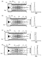
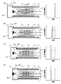
続いて、開閉検知センサ1による開閉検知について説明する。図5(a)から図5(d)は、開閉検知センサ1がオン状態からオフ状態に変化する過程で、FBG部26のブラッグ波長を含む広帯域幅の光を光ファイバ25に入射した場合の反射光のスペクトル(以下、反射光スペクトルという。)を示す図である。図5(a)はオン状態に対応する。図5(b)はオフ状態への変化を開始してから係止部30cがフランジ23aに当接するまでの間に対応する。図5(c)は係止部30cがフランジ23aに当接してからオフ状態になるまでの間に対応する。図5(d)はオフ状態に対応する。図5(a)から図5(d)の反射光スペクトルを示す図において、横軸は反射光の波長に対応し、縦軸は反射光の強度に対応する。なお、図5(a)から図5(d)には、各状態に対応するセンサ部20の状態を模式的に示す図を併記している。また、図5(d)では、図2(b)と同様、説明のため移動ベース23の移動量を大きく描いている。
Subsequently, opening / closing detection by the opening / closing detection sensor 1 will be described. FIG. 5A to FIG. 5D show the case where light having a wide bandwidth including the Bragg wavelength of the FBG unit 26 is incident on the optical fiber 25 in the process in which the open / close detection sensor 1 changes from the on state to the off state. It is a figure which shows the spectrum (henceforth a reflected light spectrum) of reflected light. FIG. 5A corresponds to the ON state. FIG. 5B corresponds to a period from when the change to the OFF state is started until the locking portion 30c comes into contact with the flange 23a. FIG. 5C corresponds to the period from when the locking portion 30c comes into contact with the flange 23a to when it is turned off. FIG. 5D corresponds to the off state. 5A to 5D, the horizontal axis corresponds to the wavelength of the reflected light, and the vertical axis corresponds to the intensity of the reflected light. FIGS. 5A to 5D also include diagrams schematically showing the state of the sensor unit 20 corresponding to each state. Further, in FIG. 5D, as in FIG. 2B, the movement amount of the movement base 23 is drawn large for explanation.
オン状態にある場合、図5(a)に示すように、反射光スペクトルは、FBG部26のブラッグ波長である波長λ1にピークを有する。オフ状態への変化を開始してから係止部30cがフランジ23aに当接するまでの間は、上述のとおり、移動ベース23は移動しない。そのため、図5(b)に示すように、反射光スペクトルは、FBG部26のブラッグ波長λ1にピークを有する。係止部30cがフランジ23aに当接してからオフ状態になるまでの間では、移動部材30の移動に伴って移動ベース23も固定ベース22から離れる方向に移動する。そのため、FBG部26のブラッグ波長は、図5(c)に示すように、移動部材30の移動に伴って、波長が大きくなる方向にシフトする。そして、オフ状態になると、図5(d)に示すように、反射光スペクトルは、固定ベース22と移動ベース23との間の距離xに対応するFBG部26のブラッグ波長である波長λ2にピークを有する状態になる。なお、図5(c)、図5(d)では、変動前のピーク位置を破線で示している。
In the ON state, as shown in FIG. 5A, the reflected light spectrum has a peak at the wavelength λ1, which is the Bragg wavelength of the FBG section 26. As described above, the moving base 23 does not move during the period from the start of the change to the off state until the locking portion 30c contacts the flange 23a. Therefore, as shown in FIG. 5B, the reflected light spectrum has a peak at the Bragg wavelength λ <b> 1 of the FBG portion 26. The moving base 23 moves away from the fixed base 22 as the moving member 30 moves from when the locking portion 30c comes into contact with the flange 23a until it is turned off. Therefore, the Bragg wavelength of the FBG section 26 is shifted in a direction in which the wavelength increases as the moving member 30 moves, as shown in FIG. In the OFF state, as shown in FIG. 5D, the reflected light spectrum peaks at a wavelength λ2 that is the Bragg wavelength of the FBG section 26 corresponding to the distance x between the fixed base 22 and the moving base 23. It will be in the state which has. In FIGS. 5C and 5D, the peak position before the change is indicated by a broken line.
また、図6(a)から図6(d)は、開閉検知センサ1がオフ状態からオン状態に変化する過程で、FBG部26のブラッグ波長を含む広帯域幅の光を光ファイバ25に入射した場合の反射光スペクトルを示す図である。図6(a)はオフ状態に対応する。図6(b)はオン状態への変化を開始してから係止部30cがフランジ23aより離脱するまでの間に対応する。図6(c)は係止部30cがフランジ23aより離脱してからオン状態になるまでの間に対応する。図6(d)はオン状態に対応する。図6(a)から図6(d)の反射光スペクトルを示す図において、横軸は反射光の波長に対応し、縦軸は反射光の強度に対応する。なお、図6(a)から図6(d)には、各状態に対応するセンサ部20の状態を模式的に示す図を併記している。また、図6(a)では、図2(b)及び図5(d)と同様、説明のため、移動ベース23の移動量を大きく描いている。
FIG. 6A to FIG. 6D show that light having a wide bandwidth including the Bragg wavelength of the FBG unit 26 is incident on the optical fiber 25 in the process in which the open / close detection sensor 1 changes from the off state to the on state. It is a figure which shows the reflected light spectrum in a case. FIG. 6A corresponds to the off state. FIG. 6B corresponds to the period from the start of the change to the ON state until the locking portion 30c is detached from the flange 23a. FIG. 6C corresponds to the period from when the locking portion 30c is released from the flange 23a until it is turned on. FIG. 6D corresponds to the ON state. 6A to 6D, the horizontal axis corresponds to the wavelength of the reflected light, and the vertical axis corresponds to the intensity of the reflected light. FIGS. 6A to 6D also include diagrams schematically showing the state of the sensor unit 20 corresponding to each state. Further, in FIG. 6A, the amount of movement of the movement base 23 is greatly illustrated for the sake of explanation, as in FIGS. 2B and 5D.
オフ状態にある場合、図6(a)に示すように、反射光スペクトルは、固定ベース22と移動ベース23との間の距離xに対応するFBG部26のブラッグ波長である波長λ2にピークを有する。オン状態への変化を開始してから係止部30cがフランジ23aより離脱するまでの間は、移動部材30の移動に伴って移動ベース23も固定ベース22に近づく方向に移動する。そのため、FBG部26のブラッグ波長は、図6(b)に示すように、移動部材30の移動に伴って、波長が小さくなる方向にシフトする。係止部30cがフランジ23aより離脱してからオン状態になるまでの間では、移動ベース23は固定ベース22に当接する状態になり、移動ベース23は移動しない。そのため、図6(c)に示すように、反射光スペクトルは、FBG部26のブラッグ波長λ1にピークを有する。そして、オン状態でも、移動ベース23は固定ベース22に当接する状態であるため、図6(d)に示すように、反射光スペクトルは、FBG部26のブラッグ波長λ1にピークを有する。なお、図6(b)から図6(d)では、変動前のピーク位置を破線で示している。
When in the off state, as shown in FIG. 6A, the reflected light spectrum has a peak at the wavelength λ2, which is the Bragg wavelength of the FBG unit 26 corresponding to the distance x between the fixed base 22 and the moving base 23. Have. The movement base 23 also moves in the direction approaching the fixed base 22 with the movement of the moving member 30 from the start of the change to the ON state to the time when the locking portion 30c is detached from the flange 23a. Therefore, the Bragg wavelength of the FBG section 26 is shifted in the direction in which the wavelength decreases as the moving member 30 moves, as shown in FIG. The moving base 23 is in contact with the fixed base 22 until the locking portion 30c is released from the flange 23a and is turned on, and the moving base 23 does not move. Therefore, as shown in FIG. 6C, the reflected light spectrum has a peak at the Bragg wavelength λ <b> 1 of the FBG portion 26. Even in the on state, since the moving base 23 is in contact with the fixed base 22, the reflected light spectrum has a peak at the Bragg wavelength λ 1 of the FBG portion 26, as shown in FIG. In FIG. 6B to FIG. 6D, the peak position before the change is indicated by a broken line.
図7(a)及び図7(b)は、以上で説明した開閉検知センサ1の動作状態と、反射光スペクトルにおけるピーク波長の変動との関係を示す図である。図7(a)は、オン状態からオフ状態に変化する際の反射光スペクトルにおけるピーク波長の変動を示す図であり、図7(b)は、オフ状態からオン状態に変化する際の反射光スペクトルにおけるピーク波長の変動を示す図である。図7(a)及び図7(b)において、横軸は動作状態の経時変化に対応し、縦軸はピーク波長に対応する。
7 (a) and 7 (b) are diagrams showing the relationship between the operating state of the open / close detection sensor 1 described above and the fluctuation of the peak wavelength in the reflected light spectrum. FIG. 7A is a diagram showing the fluctuation of the peak wavelength in the reflected light spectrum when changing from the ON state to the OFF state, and FIG. 7B is the reflected light when changing from the OFF state to the ON state. It is a figure which shows the fluctuation | variation of the peak wavelength in a spectrum. In FIG. 7A and FIG. 7B, the horizontal axis corresponds to the temporal change of the operating state, and the vertical axis corresponds to the peak wavelength.
本実施形態の開閉検知センサ1によれば、オン状態からオフ状態に変化する際、あるいは、オフ状態からオン状態に変化する際に、移動部材30の移動全体ではなく、特定位置(係止部30cがフランジ23aと当接する位置)におけるわずかな移動によりFBG部26のブラッグ波長が変動する。上述のとおり、FBG部26のブラック波長を変動させる移動ベース23の移動量は数十マイクロメートルである。この移動ベース23の移動量は、移動部材30の移動量(例えば、10mm程度)に比べて極めて小さいため、ブラッグ波長の変動は極めて短時間で生じることになる。したがって、FBG部26のブラッグ波長は、図7(a)、図7(b)に示すように、移動部材30が特定位置を通過するタイミングで瞬間的(ステップ状)に変動することになる。
According to the open / close detection sensor 1 of the present embodiment, when changing from the on state to the off state, or when changing from the off state to the on state, not the entire movement of the moving member 30 but the specific position (the locking portion). The Bragg wavelength of the FBG portion 26 varies due to slight movement at a position where 30c comes into contact with the flange 23a. As described above, the moving amount of the moving base 23 that varies the black wavelength of the FBG unit 26 is several tens of micrometers. Since the moving amount of the moving base 23 is extremely smaller than the moving amount of the moving member 30 (for example, about 10 mm), the fluctuation of the Bragg wavelength occurs in a very short time. Therefore, as shown in FIGS. 7A and 7B, the Bragg wavelength of the FBG section 26 changes instantaneously (step-like) at the timing when the moving member 30 passes through the specific position.
以上のような構成を有する開閉検知センサ1によれば、検知対象物の開閉に伴って移動部材30が移動し、当該移動部材30が特定位置に到達したときに、瞬間的にFBG部26に張力が付与される、あるいは、FBG部26に付与されていた張力が瞬間的に開放される。そのため、検知対象物の開閉状態が極めてゆっくりと変更された場合でも、当該開閉状態の変更をブラッグ波長のステップ状のシフトとして確実に検知することができる。
According to the open / close detection sensor 1 having the above-described configuration, the moving member 30 moves as the detection target opens and closes, and when the moving member 30 reaches a specific position, the FBG unit 26 instantaneously moves. The tension is applied or the tension applied to the FBG unit 26 is released momentarily. Therefore, even when the open / close state of the detection target is changed very slowly, the change in the open / close state can be reliably detected as a step-like shift of the Bragg wavelength.
また、オン状態及びオフ状態のいずれの場合であっても、光ファイバ25に作用する外力は極めて小さいため、オン状態又はオフ状態が長期間にわたって持続する状況下であっても、光ファイバ25の形状が固定化されてしまい検知感度が低下することもない。
Moreover, since the external force acting on the optical fiber 25 is extremely small regardless of whether the optical fiber 25 is in the on state or the off state, The shape is not fixed and the detection sensitivity is not lowered.
なお、近年、FBG部を備える光ファイバを使用した歪みゲージでは、光ファイバの軸方向に沿う張力(プリテンション)がFBG部に付与された状態で、光ファイバがセンサベースに固定支持される構成が広く採用されている。このような、FBG部に張力が付与される構成では、歪みゲージは引張方向の応力だけでなく圧縮方向の応力も検出することが可能になる。本実施形態においても、移動ベース23が固定ベース22と接触している状況下において、FBG部26に光ファイバの軸方向に沿う張力が付与された状態で、光ファイバ25がセンサベース24に固定される構成を採用することができる。
In recent years, in a strain gauge using an optical fiber having an FBG part, the optical fiber is fixedly supported on the sensor base in a state where a tension (pretension) along the axial direction of the optical fiber is applied to the FBG part. Is widely adopted. In such a configuration in which tension is applied to the FBG portion, the strain gauge can detect not only the stress in the tensile direction but also the stress in the compression direction. Also in this embodiment, the optical fiber 25 is fixed to the sensor base 24 in a state where the tension along the axial direction of the optical fiber is applied to the FBG portion 26 in a state where the moving base 23 is in contact with the fixed base 22. Can be adopted.
このような構成を採用した場合、移動部材30がケース10内を移動する際に発生する振動等に起因して移動ベース23に振動等が発生すると、FGB部26はこのような振動等も検知してしまう。その結果、オン状態からオフ状態に移行する際のブラッグ波長の変動や、オフ状態からオン状態に移行する際のブラッグ波長の変動にノイズが重畳する場合もある。
When such a configuration is employed, when vibration or the like occurs in the moving base 23 due to vibration or the like generated when the moving member 30 moves in the case 10, the FGB unit 26 also detects such vibration or the like. Resulting in. As a result, noise may be superimposed on the fluctuation of the Bragg wavelength when shifting from the on state to the off state or the fluctuation of the Bragg wavelength when shifting from the off state to the on state.
このような状態でも、オン状態とオフ状態とを区別するための適切な閾値を設定することで開閉状態の検知は可能である。しかしながら、このようなノイズの重畳を回避する観点では、光ファイバ25は、移動ベース23が固定ベース22と接触している状況下において、FBG部26に光ファイバの軸方向に沿う圧縮力(回折格子の間隔が狭まる方向の力)が付与された状態、あるいは、FBG部26に実質的に張力が付与されていない状態で、光ファイバ25がセンサベース24に固定される構成を採用することが好ましい。このような構成を採用することで、ノイズの重畳のない、ブラッグ波長の変動データを取得することが可能になる。
Even in such a state, it is possible to detect the open / closed state by setting an appropriate threshold value for distinguishing between the on state and the off state. However, from the viewpoint of avoiding such superposition of noise, the optical fiber 25 has a compressive force (diffraction) along the axial direction of the optical fiber on the FBG portion 26 in a state where the moving base 23 is in contact with the fixed base 22. It is possible to adopt a configuration in which the optical fiber 25 is fixed to the sensor base 24 in a state in which a force in a direction in which the interval between the lattices is narrowed) or a state in which no tension is substantially applied to the FBG portion 26. preferable. By adopting such a configuration, it is possible to acquire Bragg wavelength fluctuation data without noise superposition.
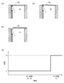
図8(a)から図8(d)は開閉検知センサ1をマンホール蓋の開閉検知に適用した事例を示す図である。図8(a)は閉状態にあるマンホール蓋を示す模式図である。図8(b)は閉状態から開状態への移行途中にあるマンホール蓋を示す模式図である。図8(c)は開状態にあるマンホール蓋を示す模式図である。また、図8(d)は、図8(a)から図8(c)への開閉状態の変更に伴うFBG部26のブラッグ波長の変動を示す模式図である。なお、図8(a)から図8(c)では、マンホール蓋及びマンホールは断面を描き、開閉検知センサ1は側面を描いている。
FIG. 8A to FIG. 8D are diagrams showing an example in which the open / close detection sensor 1 is applied to open / close detection of a manhole cover. FIG. 8A is a schematic diagram showing the manhole cover in the closed state. FIG. 8B is a schematic diagram showing the manhole cover in the middle of the transition from the closed state to the open state. FIG. 8C is a schematic diagram showing the manhole cover in the open state. FIG. 8D is a schematic diagram showing the variation of the Bragg wavelength of the FBG section 26 due to the change of the open / close state from FIG. 8A to FIG. 8C. In FIGS. 8A to 8C, the manhole cover and the manhole have a cross section, and the open / close detection sensor 1 has a side surface.
図8(a)に示すように、開閉検知センサ1は、閉状態にあるマンホール蓋82の裏面(マンホール81側の面)に対してケース10の軸が垂直となる状態で配置される。このとき、当接部30aはマンホール蓋82の裏面に接触している。当該状態では、移動部材30はケース10の内部に押し込まれた状態にある。したがって、移動ベース23は固定ベース22と当接しており、FBG部26のブラッグ波長は当該状態に応じた波長λ1になっている。図8(b)に示すように、マンホール蓋82が閉状態から開状態への移行途中であっても、係止部30cがフランジ23aに当接するまでの間は、移動ベース23は固定ベース22と当接しているため、FBG部26のブラッグ波長は波長λ1のままである。そして、係止部30cがフランジ23aに当接すると、上述のように、移動ベース23は固定ベース22から距離xだけ引き離される結果、FBG部26のブラッグ波長は瞬間的に当該状態に応じた波長λ2になる。その後、図8(c)に示すように、マンホール蓋82が開状態になっても、移動ベース23と固定ベース22との間隔は距離xであるため、FBG部26のブラッグ波長は波長λ2のままである。
As shown in FIG. 8A, the open / close detection sensor 1 is arranged in a state where the axis of the case 10 is perpendicular to the back surface of the manhole cover 82 in the closed state (the surface on the manhole 81 side). At this time, the contact portion 30 a is in contact with the back surface of the manhole cover 82. In this state, the moving member 30 is pushed into the case 10. Therefore, the moving base 23 is in contact with the fixed base 22, and the Bragg wavelength of the FBG portion 26 is the wavelength λ1 corresponding to the state. As shown in FIG. 8B, even when the manhole cover 82 is in the process of transition from the closed state to the open state, the moving base 23 is fixed to the fixed base 22 until the locking portion 30c comes into contact with the flange 23a. Therefore, the Bragg wavelength of the FBG portion 26 remains at the wavelength λ1. When the locking portion 30c comes into contact with the flange 23a, as described above, the moving base 23 is separated from the fixed base 22 by the distance x. As a result, the Bragg wavelength of the FBG portion 26 instantaneously depends on the state. λ2. After that, as shown in FIG. 8C, even when the manhole cover 82 is in the open state, the distance between the moving base 23 and the fixed base 22 is the distance x, so the Bragg wavelength of the FBG portion 26 is the wavelength λ2. It remains.
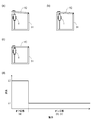
図9(a)から図9(d)は開閉検知センサ1を開き戸の開閉検知に適用した事例を示す図である。閉状態から開状態への動作についての開閉検知は、図8(a)から図8(d)に示すマンホール蓋の事例と同様であるので、ここでは、開状態から閉状態への動作についての開閉検知を説明する。図9(a)は開状態にある開き戸を示す模式図である。図9(b)は開状態から閉状態への移行途中にある開き戸を示す模式図である。図9(c)は閉状態にある開き戸を示す模式図である。また、図9(d)は、図9(a)から図9(c)への開閉状態の変更に伴うFBG部26のブラッグ波長の変動を示す模式図である。なお、図9(a)から図9(c)では、サーバラックが備える開き戸を上方から見た図であり、天板及びサーバラックの内部構造の記載を省略している。また、開閉検知センサ1はサーバラックの底板上に設置されている。
9 (a) to 9 (d) are diagrams showing an example in which the open / close detection sensor 1 is applied to open / close detection of a hinged door. Since the opening / closing detection for the operation from the closed state to the open state is the same as the case of the manhole cover shown in FIGS. 8A to 8D, here, the operation from the open state to the closed state is described. Open / close detection will be described. Fig.9 (a) is a schematic diagram which shows the hinged door in an open state. FIG.9 (b) is a schematic diagram which shows the hinged door in the middle of the transition from an open state to a closed state. FIG.9 (c) is a schematic diagram which shows the hinged door in a closed state. FIG. 9D is a schematic diagram showing the variation of the Bragg wavelength of the FBG section 26 due to the change of the open / close state from FIG. 9A to FIG. 9C. In addition, in FIG. 9A to FIG. 9C, the hinged door included in the server rack is viewed from above, and the description of the top plate and the internal structure of the server rack is omitted. The open / close detection sensor 1 is installed on the bottom plate of the server rack.
図9(c)に示すように、開閉検知センサ1は、閉状態にある開き戸92の裏面(サーバラック91において内側の面)に対してケース10の軸が垂直となる状態で配置される。このとき、当接部30aは開き戸92の裏面に接触する。一方、開き戸92が開状態にある場合、当接部30aは開き戸92の裏面から離れており、移動部材30はケース10の先端部10bから軸方向外側に突出している。このとき、移動ベース23は固定ベース22から距離xだけ引き離されているため、FBG部26のブラッグ波長は当該状態に応じた波長λ2になっている。図9(b)に示すように、開き戸92が開状態から閉状態への移行途中であっても、開き戸92が当接部30aに当接した後、移動部材30がケース10の内部に押し込まれて、係止部30cがフランジ23aから離脱するまでの間は、移動ベース23は固定ベース22と距離xをおいて離間しているため、FBG部26のブラッグ波長は波長λ2のままである。そして、係止部30cがフランジ23aから離脱すると、移動ベース23が固定ベース22と当接する結果、FBG部26のブラッグ波長は瞬間的に当該状態に応じた波長λ1になる。その後、図9(c)に示すように、開き戸92が閉状態になっても、移動ベース23と固定ベース22とは当接したままであるため、FBG部26のブラッグ波長は波長λ1のままである。
As shown in FIG. 9C, the open / close detection sensor 1 is arranged in a state where the axis of the case 10 is perpendicular to the back surface of the hinged door 92 in the closed state (the inner surface in the server rack 91). At this time, the contact portion 30 a contacts the back surface of the hinged door 92. On the other hand, when the hinged door 92 is in the open state, the contact portion 30 a is separated from the back surface of the hinged door 92, and the moving member 30 protrudes axially outward from the distal end portion 10 b of the case 10. At this time, since the moving base 23 is separated from the fixed base 22 by the distance x, the Bragg wavelength of the FBG unit 26 is the wavelength λ2 corresponding to the state. As shown in FIG. 9B, even when the hinged door 92 is in the process of transition from the open state to the closed state, the movable member 30 is pushed into the case 10 after the hinged door 92 abuts against the abutting portion 30a. Thus, until the locking portion 30c is detached from the flange 23a, the moving base 23 is separated from the fixed base 22 with a distance x, so the Bragg wavelength of the FBG portion 26 remains at the wavelength λ2. . And when the latching | locking part 30c remove | deviates from the flange 23a, as a result of the movement base 23 contact | abutting with the fixed base 22, the Bragg wavelength of the FBG part 26 will become wavelength (lambda) 1 according to the said state instantaneously. Thereafter, as shown in FIG. 9C, even when the hinged door 92 is closed, the moving base 23 and the fixed base 22 remain in contact with each other, so the Bragg wavelength of the FBG section 26 remains at the wavelength λ1. It is.
なお、上述のように、ブラッグ波長は、光ファイバの屈折率と回折格子の格子間隔とによって定まる。そのため、温度が変化した場合の屈折率の変動や、光ファイバの膨張・収縮によってもブラッグ波長が変動することになる。そのため、仮に、短時間で急激な温度変化が発生した場合には、ブラッグ波長の変動が、移動ベース23の移動に起因して発生したものであるか、温度変化に起因して発生したものであるかを区別することができない可能性も否定できない。
As described above, the Bragg wavelength is determined by the refractive index of the optical fiber and the grating interval of the diffraction grating. Therefore, the Bragg wavelength also fluctuates due to changes in the refractive index when the temperature changes and expansion / contraction of the optical fiber. Therefore, if an abrupt temperature change occurs in a short time, the Bragg wavelength fluctuation is caused by the movement of the moving base 23 or caused by the temperature change. It cannot be denied that there is a possibility that it cannot be distinguished.
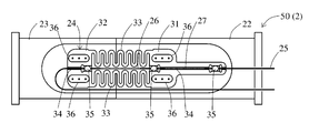
この対策として、温度補正用のFBG部を設けることができる。図10は、本実施形態における他の開閉検知センサ2が備えるセンサ部50の構造を示す図である。センサ部50は、温度補正用のFBG部27をさらに備える点で、開閉検知センサ1のセンサ部20の構成と異なる。他の構成はセンサ部20と同一であり、センサ部20と同様の作用効果を奏する構成要素には同一の符号を付している。
As a countermeasure, an FBG part for temperature correction can be provided. FIG. 10 is a diagram illustrating a structure of a sensor unit 50 provided in another open / close detection sensor 2 according to the present embodiment. The sensor unit 50 is different from the configuration of the sensor unit 20 of the open / close detection sensor 1 in that it further includes an FBG unit 27 for temperature correction. Other configurations are the same as those of the sensor unit 20, and the same reference numerals are given to components that exhibit the same operational effects as the sensor unit 20.
図10に示すように、温度補正用のFBG部27は、固定ベース22に固定された板状部31上に固定することができる。図10の例では、FBG部26及びFBG部27は、同一の光ケーブル25に隣接して形成されている。ここでは、FBG部26のブラッグ波長とFBG部27のブラッグ波長を異ならせている。このような構成は、例えば、同一の光ファイバ25上に、同一のブラッグ波長を有するFBG部を隣接して形成し、光ファイバ25をセンサベース24に固定材35で固定する際に、FBG部26に付与されるプリテンションと、FBG部27に付与されるプリテンションとを異ならせることで実現可能である。
As shown in FIG. 10, the temperature correcting FBG part 27 can be fixed on a plate-like part 31 fixed to the fixed base 22. In the example of FIG. 10, the FBG portion 26 and the FBG portion 27 are formed adjacent to the same optical cable 25. Here, the Bragg wavelength of the FBG unit 26 is different from the Bragg wavelength of the FBG unit 27. In such a configuration, for example, when the FBG portion having the same Bragg wavelength is formed adjacently on the same optical fiber 25 and the optical fiber 25 is fixed to the sensor base 24 with the fixing material 35, the FBG portion is formed. This can be realized by making the pretension applied to 26 different from the pretension applied to the FBG unit 27.
図11(a)から図11(d)は、開閉検知センサ2において温度変化が生じた場合の、反射光スペクトルの変動の一例を示す模式図である。図11(a)は、オン状態の開閉検知センサ2に、FBG部26のブラッグ波長とFBG部27のブラッグ波長とを含む広帯域幅の光を入射した場合の反射光スペクトルを示す図である。図11(b)は、オン状態の開閉検知センサ2に、温度変化(温度上昇)のみが生じた場合の反射光スペクトルにおけるピーク波長の変動を示す模式図である。図11(c)は、温度が一定の状態で、オン状態の開閉検知センサ2に、オン状態からオフ状態への変化のみが生じた場合の反射光スペクトルにおけるピーク波長の変動を示す模式図である。図11(d)は、オン状態の開閉検知センサ2に、温度変化(温度上昇)及びオン状態からオフ状態への変化が生じた場合の反射光スペクトルにおけるピーク波長の変動を示す模式図である。図11(a)から図11(d)において、横軸は反射光の波長に対応し、縦軸は反射光の強度に対応する。なお、図11(b)から図11(d)では、変動前の反射光スペクトルを破線で示している。
11 (a) to 11 (d) are schematic diagrams showing an example of fluctuations in the reflected light spectrum when a temperature change occurs in the open / close detection sensor 2. FIG. FIG. 11A is a diagram showing a reflected light spectrum when light having a wide bandwidth including the Bragg wavelength of the FBG unit 26 and the Bragg wavelength of the FBG unit 27 is incident on the open / closed detection sensor 2 in the ON state. FIG. 11B is a schematic diagram showing the fluctuation of the peak wavelength in the reflected light spectrum when only the temperature change (temperature rise) occurs in the open / closed detection sensor 2. FIG. 11C is a schematic diagram showing fluctuations in the peak wavelength in the reflected light spectrum when only the change from the on state to the off state occurs in the open / closed detection sensor 2 in a state where the temperature is constant. is there. FIG. 11D is a schematic diagram showing fluctuations in the peak wavelength in the reflected light spectrum when a temperature change (temperature increase) and a change from the on state to the off state occur in the open / closed detection sensor 2 in the on state. . In FIGS. 11A to 11D, the horizontal axis corresponds to the wavelength of the reflected light, and the vertical axis corresponds to the intensity of the reflected light. In FIGS. 11 (b) to 11 (d), the reflected light spectrum before fluctuation is indicated by a broken line.
図11(a)に示すように、特定温度でオン状態にある開閉検知センサ2の、反射光スペクトルは、FBG部26のブラッグ波長λ1とFBG部27のブラッグ波長λ3とのそれぞれにピークを有することになる。また、図11(b)に示すように、温度変化のみが生じた場合、FBG部26、温度補正用のFBG部27のいずれにも温度変化により屈折率変動及び膨張が生じる。そのため、いずれのFBG部26、27のブラッグ波長も大きくなる方向にシフトする。また、図11(c)に示すように、オン状態からオフ状態への変化のみが生じた場合、上述のように、状態変化に伴う移動ベース23の移動に応じてFBG部26のブラッグ波長は大きくなる方向にシフトする。このとき、温度補正用のFBG部27には何ら変化が生じないため、FBG部27のブラッグ波長は変動しない。
As shown in FIG. 11A, the reflected light spectrum of the open / close detection sensor 2 that is on at a specific temperature has peaks at the Bragg wavelength λ1 of the FBG unit 26 and the Bragg wavelength λ3 of the FBG unit 27, respectively. It will be. Further, as shown in FIG. 11B, when only a temperature change occurs, the refractive index variation and the expansion occur due to the temperature change in both the FBG unit 26 and the FBG unit 27 for temperature correction. For this reason, the Bragg wavelength of any of the FBG units 26 and 27 is shifted in the direction of increasing. In addition, as shown in FIG. 11C, when only the change from the on state to the off state occurs, the Bragg wavelength of the FBG unit 26 is changed according to the movement of the movement base 23 accompanying the state change as described above. Shift in the direction of increasing. At this time, since no change occurs in the temperature-correcting FBG section 27, the Bragg wavelength of the FBG section 27 does not vary.
温度変化とオン状態からオフ状態への変化とがともに生じた場合、以上の変動が組み合わさった状態になる。すなわち、図11(d)に示すように、FBG部26のブラッグ波長には温度変化に応じた波長シフトとオン状態からオフ状態への変化に応じた波長シフトとが重畳して発生し、FGB部27のブラッグ波長には温度変化に応じた波長シフトのみが発生することになる。
When the temperature change and the change from the on state to the off state occur together, the above fluctuations are combined. That is, as shown in FIG. 11 (d), the Bragg wavelength of the FBG unit 26 is generated by superimposing the wavelength shift according to the temperature change and the wavelength shift according to the change from the on state to the off state. Only the wavelength shift corresponding to the temperature change occurs in the Bragg wavelength of the unit 27.
例えば、図11(d)において、FBG部27のブラッグ波長のシフト量が0.3nmであり、FBG部26のブラッグ波長のシフト量が0.6nmであるとする。この場合、図11(b)における温度変化のみによる波長シフト量が、FBG部26とFBG部27とで同一であると仮定すると、0.6nm-0.3nm=0.3nmが図11(c)におけるオン状態からオフ状態への変化のみによるブラッグ波長のシフト量ということになる。このように、FBG部26のブラッグ波長のシフト量と、FBG部27のブラッグ波長のシフト量とを計測することで、温度補正を実現することが可能になる。
For example, in FIG. 11D, it is assumed that the shift amount of the Bragg wavelength of the FBG unit 27 is 0.3 nm and the shift amount of the Bragg wavelength of the FBG unit 26 is 0.6 nm. In this case, assuming that the wavelength shift amount due to only the temperature change in FIG. 11B is the same in the FBG portion 26 and the FBG portion 27, 0.6 nm−0.3 nm = 0.3 nm is shown in FIG. ), The amount of shift of the Bragg wavelength due to only the change from the on state to the off state. As described above, by measuring the shift amount of the Bragg wavelength of the FBG unit 26 and the shift amount of the Bragg wavelength of the FBG unit 27, it is possible to realize temperature correction.
以上で説明したように、本発明によれば、検知対象物の開閉状態が極めてゆっくりと変更された場合や開閉状態の変更頻度が極めて少ない状況下でも、当該開閉状態の変更を確実に検知することができる。
As described above, according to the present invention, even when the open / close state of the detection target is changed very slowly or even under a situation where the change frequency of the open / close state is extremely low, the change in the open / close state is reliably detected. be able to.
なお、上述した実施形態は本発明の技術的範囲を制限するものではなく、既に記載したもの以外でも、本発明の範囲内で種々の変形や応用が可能である。例えば、上記実施形態では、特に好ましい形態として、光ファイバ25のFBG部26を直線状に配置し、当該FBG部26の軸に沿って移動部材30が移動する構成としたが、移動ベースと固定ベースとの間隔に応じてブラッグ波長が変動する構成であればFBG部と移動部材の配置は任意である。また、上記実施形態では、係止部30cとして、移動ベース23に当接して移動ベース23を直接的に移動させる構成を説明したが、移動ベース23に直接当接することなく、間接的に移動ベース23を移動させる構成を採用することも可能である。加えて、係止部30cの形状も任意に変更可能である。同様に、ケース10や移動部材30の形状も円筒状に限定されず、例えば、角筒状等の他の中空形状を採用することもできる。
The above-described embodiments do not limit the technical scope of the present invention, and various modifications and applications can be made within the scope of the present invention other than those already described. For example, in the above embodiment, as a particularly preferable form, the FBG portion 26 of the optical fiber 25 is linearly arranged, and the moving member 30 moves along the axis of the FBG portion 26. The arrangement of the FBG portion and the moving member is arbitrary as long as the Bragg wavelength varies according to the distance from the base. In the above-described embodiment, the configuration in which the moving base 23 is moved directly by contacting the moving base 23 as the locking portion 30c has been described. However, the moving base 23 is indirectly moved without directly contacting the moving base 23. It is also possible to adopt a configuration in which 23 is moved. In addition, the shape of the locking portion 30c can be arbitrarily changed. Similarly, the shape of the case 10 and the moving member 30 is not limited to a cylindrical shape, and other hollow shapes such as a rectangular tube shape may be employed.
また、上述の実施形態では、オフ状態における移動部材30の位置(第2の位置)を、ケース10の内周面に形成した段差10cにより規定したが、当接部30aと検知対象物とが離間したときに移動部材30の位置を規定できる構成であればその構造は任意である。例えば、移動ベース23の移動方向を規制するレール41の端部に螺合されたボルト44と移動ベース23とが当接する位置を、オフ状態における移動部材30の位置として規定することも可能である。
Further, in the above-described embodiment, the position (second position) of the moving member 30 in the off state is defined by the step 10c formed on the inner peripheral surface of the case 10, but the contact portion 30a and the detection target are The structure is arbitrary as long as the position of the moving member 30 can be defined when separated. For example, the position where the bolt 44 screwed to the end portion of the rail 41 that regulates the moving direction of the moving base 23 and the moving base 23 abut can be defined as the position of the moving member 30 in the off state. .
さらに、上述の実施形態では、付勢部材としてつる巻きバネ12を例示したが、公知の任意の構造の付勢部材を使用することができる。また、移動部材30は検知対象物の開閉に伴ってオン状態とオフ状態とにわたって移動可能であればよく、付勢部材を用いることは必須ではない。例えば、付勢部材に代えて機械的な機構を採用することも可能である。
Furthermore, in the above-described embodiment, the helical spring 12 is exemplified as the biasing member, but a biasing member having a known arbitrary structure can be used. Moreover, the moving member 30 should just be movable across an ON state and an OFF state with opening and closing of a detection target object, and it is not essential to use a biasing member. For example, it is possible to employ a mechanical mechanism instead of the biasing member.
加えて、上述の実施形態では、移動部材30の軸方向の長さを、センサ部20を内部に収容できる程度の長さとしたが、移動部材30によりセンサ部20を収容することは必須ではなく、移動部材30の軸方向の長さは任意である。
In addition, in the above-described embodiment, the length of the moving member 30 in the axial direction is set to such a length that the sensor unit 20 can be accommodated therein. However, it is not essential to accommodate the sensor unit 20 by the moving member 30. The length of the moving member 30 in the axial direction is arbitrary.
また、上記実施形態では、移動部材30が検知対象物に当接する当接部30aを備える構成を開示したが、移動部材30は検知対象物の開閉に応じた移動が可能であればよく、検知対象物に直接接触することは必須ではない。例えば、図8(a)から図8(d)に示すマンホール蓋の開閉を検知する事例では、例えば、一方端にマンホール蓋82に当接する当接部を備え、他方端にマンホール蓋82の開閉に応じて水平方向に移動するアクチュエータを備えるリンク機構を配置するとともに、ケース10の軸を水平として開閉検知センサ1をアクチュエータに連結して配置する構成を採用すれることも可能である。
Moreover, in the said embodiment, although the structure provided with the contact part 30a in which the moving member 30 contact | abuts a detection target object was disclosed, the movement member 30 should just be able to move according to opening and closing of a detection target object, and is detected. Direct contact with the object is not essential. For example, in the case of detecting the opening and closing of the manhole cover shown in FIGS. 8A to 8D, for example, a contact portion that contacts the manhole cover 82 is provided at one end, and the manhole cover 82 is opened and closed at the other end. It is also possible to employ a configuration in which a link mechanism including an actuator that moves in the horizontal direction according to the position is disposed, and the opening / closing detection sensor 1 is connected to the actuator with the axis of the case 10 horizontal.
本発明によれば、検知対象物の開閉状態が極めてゆっくりと変更された場合や開閉状態の変更頻度が極めて少ない状況下でも当該開閉状態の変更を確実に検知することができ、開閉検知センサとして有用である。
According to the present invention, even when the open / close state of the detection target is changed very slowly or under a situation where the change frequency of the open / close state is extremely low, the change of the open / close state can be reliably detected. Useful.
1、2 開閉検知センサ
10 ケース
12 つる巻きバネ(付勢部材)
20、50 センサ部
21 ベース部材
22 固定ベース(第1のベース部材)
23 移動ベース(第2のベース部材)
24 センサベース
25 光ファイバ
26 FBG部
27 FBG部(温度補償用)
30 移動部材
30a 当接部
30c 係止部 1, 2 Open /close detection sensor 10 Case 12 Helical spring (biasing member)
20, 50Sensor unit 21 Base member 22 Fixed base (first base member)
23 Moving base (second base member)
24sensor base 25 optical fiber 26 FBG part 27 FBG part (for temperature compensation)
30 movingmember 30a contact part 30c locking part
10 ケース
12 つる巻きバネ(付勢部材)
20、50 センサ部
21 ベース部材
22 固定ベース(第1のベース部材)
23 移動ベース(第2のベース部材)
24 センサベース
25 光ファイバ
26 FBG部
27 FBG部(温度補償用)
30 移動部材
30a 当接部
30c 係止部 1, 2 Open /
20, 50
23 Moving base (second base member)
24
30 moving
Claims (7)
- 光ファイバを利用した開閉検知センサであって、
第1のベース部材と、
前記第1のベース部材に対して移動可能に配置される第2のベース部材と、
前記第1のベース部材と前記第2のベース部材との間隔に応じてブラッグ波長が変動するFBG(Fiber Bragg Grating)部を備える光ファイバと、
検知対象物の開閉に伴って、前記検知対象物の開状態及び閉状態の一方の状態に対応する第1の位置と、他方の状態に対応する第2の位置とにわたって移動する移動部材と、
前記移動部材に設けられ、前記第1の位置と前記第2の位置の間に位置する第3の位置と前記第2の位置との間において前記第2のベース部材と当接して前記第2のベース部材を前記移動部材とともに移動させ、前記第2のベース部材を前記第1のベース部材から離れる方向に移動させる係止部と、
を備える開閉検知センサ。 An open / close detection sensor using an optical fiber,
A first base member;
A second base member movably disposed with respect to the first base member;
An optical fiber including an FBG (Fiber Bragg Grating) portion in which a Bragg wavelength varies according to a distance between the first base member and the second base member;
A moving member that moves over a first position corresponding to one of an open state and a closed state of the detection target and a second position corresponding to the other state as the detection target opens and closes;
The second member is provided on the moving member and is in contact with the second base member between a third position and the second position located between the first position and the second position. A locking portion that moves the base member together with the moving member, and moves the second base member in a direction away from the first base member;
An open / close detection sensor. - 前記光ファイバの前記FBG部を含む部分が直線状に配置され、前記第2のベース部材及び前記移動部材が当該直線状に配置された光ファイバの軸方向に沿って移動する請求項1記載の開閉検知センサ。 The portion including the FBG portion of the optical fiber is arranged in a straight line, and the second base member and the moving member move along the axial direction of the optical fiber arranged in the straight line. Open / close detection sensor.
- 前記移動部材に対して、前記第1の位置から前記第2の位置へ向かう方向に付勢力を付与する付勢部材をさらに備える請求項1又は請求項2に記載の開閉検知センサ。 The open / close detection sensor according to claim 1 or 2, further comprising a biasing member that applies a biasing force to the moving member in a direction from the first position toward the second position.
- 前記移動部材が前記検知対象物に当接する当接部を備える請求項1から請求項3のいずれか1項に記載の開閉検知センサ。 The opening / closing detection sensor according to any one of claims 1 to 3, wherein the moving member includes a contact portion that contacts the detection target.
- 前記移動部材が中空部材により構成され、前記第1のベース部材、第2のベース部材及び光ファイバが、前記移動部材の内部に配置される請求項1から請求項4のいずれか1項に記載の開閉検知センサ。 The said moving member is comprised by the hollow member, The said 1st base member, the 2nd base member, and an optical fiber are arrange | positioned inside the said moving member, The any one of Claims 1-4. Open / close detection sensor.
- 前記第1のベース部材と前記第2のベース部材とが接触している状況下において、前記FBG部に前記光ファイバの軸方向に沿う圧縮力が付与された状態で、前記光ファイバが前記第1のベース部材及び第2のベース部材に固定される、請求項1から請求項5のいずれか1項に記載の開閉検知センサ。 In a state where the first base member and the second base member are in contact with each other, the optical fiber is in the state in which a compressive force along the axial direction of the optical fiber is applied to the FBG portion. The open / close detection sensor according to claim 1, wherein the open / close detection sensor is fixed to the first base member and the second base member.
- 前記第1のベース部材上に温度補償用のFBG部をさらに備える請求項1から請求項6のいずれか1項に記載の開閉検知センサ。 The open / close detection sensor according to any one of claims 1 to 6, further comprising an FBG portion for temperature compensation on the first base member.
Priority Applications (3)
| Application Number | Priority Date | Filing Date | Title |
|---|---|---|---|
| EP19796250.9A EP3789737B1 (en) | 2018-05-04 | 2019-04-26 | Open/close detection sensor |
| US16/621,209 US10830944B2 (en) | 2018-05-04 | 2019-04-26 | Opening and closing detection sensor |
| JP2020517069A JP7045734B2 (en) | 2018-05-04 | 2019-04-26 | Open / close detection sensor |
Applications Claiming Priority (2)
| Application Number | Priority Date | Filing Date | Title |
|---|---|---|---|
| JP2018088974 | 2018-05-04 | ||
| JP2018-088974 | 2018-05-04 |
Publications (1)
| Publication Number | Publication Date |
|---|---|
| WO2019212048A1 true WO2019212048A1 (en) | 2019-11-07 |
Family
ID=68386374
Family Applications (1)
| Application Number | Title | Priority Date | Filing Date |
|---|---|---|---|
| PCT/JP2019/018000 WO2019212048A1 (en) | 2018-05-04 | 2019-04-26 | Open/close detection sensor |
Country Status (4)
| Country | Link |
|---|---|
| US (1) | US10830944B2 (en) |
| EP (1) | EP3789737B1 (en) |
| JP (1) | JP7045734B2 (en) |
| WO (1) | WO2019212048A1 (en) |
Families Citing this family (1)
| Publication number | Priority date | Publication date | Assignee | Title |
|---|---|---|---|---|
| CN115164729B (en) * | 2022-06-10 | 2023-05-30 | 澳门大学 | Fiber bragg grating displacement sensor with positive and negative bidirectional measurement and without influence of vibration |
Citations (8)
| Publication number | Priority date | Publication date | Assignee | Title |
|---|---|---|---|---|
| JPH01110217A (en) | 1987-10-23 | 1989-04-26 | Hitachi Ltd | Displacement sensor |
| JP2000111319A (en) * | 1998-09-30 | 2000-04-18 | Ntt Advanced Technology Corp | Optical fiber sensor |
| JP2001107615A (en) * | 1999-10-12 | 2001-04-17 | Sumitomo Electric Ind Ltd | Locking detection sensor of manhole cover and locking monitor system |
| JP2003322805A (en) | 2002-05-02 | 2003-11-14 | Hitachi Cable Ltd | Cover opening/closing detection sensor |
| JP2006214844A (en) * | 2005-02-03 | 2006-08-17 | Fujikura Ltd | Movable body displacement detector using optical fiber |
| JP2007024527A (en) | 2005-07-12 | 2007-02-01 | Fiberlabs Inc | Optical fiber sensor and sensor system |
| JP2010140501A (en) | 2004-09-30 | 2010-06-24 | Mitsubishi Electric Corp | Tension sensor |
| CN107390287A (en) * | 2017-09-13 | 2017-11-24 | 济南星冉信息技术有限公司 | A kind of optical fiber type well lid state monitoring apparatus |
Family Cites Families (23)
| Publication number | Priority date | Publication date | Assignee | Title |
|---|---|---|---|---|
| JPH0854551A (en) * | 1994-08-12 | 1996-02-27 | Furukawa Electric Co Ltd:The | Cap opening-closing sensor of optical fiber connecting box |
| DE19808222A1 (en) * | 1998-02-27 | 1999-09-02 | Abb Research Ltd | Fiber Bragg grating pressure sensor with integrable fiber Bragg grating temperature sensor |
| US6768825B2 (en) * | 1998-05-06 | 2004-07-27 | Weatherford/Lamb, Inc. | Optical sensor device having creep-resistant optical fiber attachments |
| CN1153054C (en) * | 1998-12-04 | 2004-06-09 | 塞德拉公司 | Bragg grating pressure sensor |
| US20060214068A1 (en) * | 2005-03-25 | 2006-09-28 | Fibera, Inc. | Fiber optic monitor for railroad switch |
| US20070193362A1 (en) * | 2006-02-06 | 2007-08-23 | Ferguson Stephen K | Fiber optic strain gage |
| DE102006032999B4 (en) * | 2006-07-17 | 2011-04-14 | Continental Automotive Gmbh | Sensor assembly with a sensor band, in particular with a fiber-optic sensor band |
| CN100381845C (en) * | 2006-07-20 | 2008-04-16 | 上海交通大学 | Optical fiber grating door opening and closing state sensor probe |
| US7974503B2 (en) * | 2007-06-22 | 2011-07-05 | National Chiao Tung University | Fiber grating sensor |
| US7856888B2 (en) * | 2007-11-15 | 2010-12-28 | Micron Optics Inc. | Fiber optic strain gage and carrier |
| US20090285521A1 (en) * | 2008-05-13 | 2009-11-19 | Honda Motor Co., Ltd. | Optical fiber sensor |
| US8433160B2 (en) * | 2009-01-30 | 2013-04-30 | Cleveland Electric Laboratories | Smart fastener and smart insert for a fastener using fiber Bragg gratings to measure strain and temperature |
| US8547534B2 (en) * | 2009-09-03 | 2013-10-01 | Honda Motor Co., Ltd. | Optical fiber sensor, pressure sensor, end effector and sensor signal processor |
| KR101148935B1 (en) * | 2010-05-07 | 2012-05-23 | 한국에너지기술연구원 | FBG sensor module, 2 axis FBG sensor module, 2 axis FBG sensor module manufacture equipment and 2 axis FBG sensor module manufacture method |
| CN201844820U (en) * | 2010-11-08 | 2011-05-25 | 昆明理工大学 | Double-cantilever beam type optical fiber Bragg grating displacement sensor |
| US20140123764A1 (en) * | 2012-11-05 | 2014-05-08 | Mohammad Abtahi | Fiber Bragg Grating Pressure Sensor with Adjustable Sensitivity |
| US9897497B2 (en) * | 2014-03-20 | 2018-02-20 | Halliburton Energy Services, Inc. | Temperature-compensated strain-based transducer operating on differential measurements |
| US9677963B2 (en) * | 2014-07-14 | 2017-06-13 | Weatherford Technology Holdings, Llc | Small profile pressure and temperature gauges |
| TWI529374B (en) * | 2015-01-20 | 2016-04-11 | 晉禾企業股份有限公司 | The optical fiber sensening structure both self-tensed and full jecketing with spring |
| TWI554797B (en) * | 2015-04-30 | 2016-10-21 | 晉禾企業股份有限公司 | Thermal compensated and tensed spring compact fiber bragg grating filter |
| DE102015115927A1 (en) * | 2015-09-21 | 2017-04-06 | fos4X GmbH | Sensor patch and method of making a sensor patch |
| US10663324B2 (en) * | 2016-03-01 | 2020-05-26 | Cmiws Co., Ltd. | Optical fiber sensor |
| US10976338B2 (en) * | 2017-09-11 | 2021-04-13 | Optilab, Llc | Apparatus and method for sensing acceleration or force using fiber Bragg grating (FBG) |
-
2019
- 2019-04-26 EP EP19796250.9A patent/EP3789737B1/en active Active
- 2019-04-26 JP JP2020517069A patent/JP7045734B2/en active Active
- 2019-04-26 US US16/621,209 patent/US10830944B2/en active Active
- 2019-04-26 WO PCT/JP2019/018000 patent/WO2019212048A1/en active Application Filing
Patent Citations (8)
| Publication number | Priority date | Publication date | Assignee | Title |
|---|---|---|---|---|
| JPH01110217A (en) | 1987-10-23 | 1989-04-26 | Hitachi Ltd | Displacement sensor |
| JP2000111319A (en) * | 1998-09-30 | 2000-04-18 | Ntt Advanced Technology Corp | Optical fiber sensor |
| JP2001107615A (en) * | 1999-10-12 | 2001-04-17 | Sumitomo Electric Ind Ltd | Locking detection sensor of manhole cover and locking monitor system |
| JP2003322805A (en) | 2002-05-02 | 2003-11-14 | Hitachi Cable Ltd | Cover opening/closing detection sensor |
| JP2010140501A (en) | 2004-09-30 | 2010-06-24 | Mitsubishi Electric Corp | Tension sensor |
| JP2006214844A (en) * | 2005-02-03 | 2006-08-17 | Fujikura Ltd | Movable body displacement detector using optical fiber |
| JP2007024527A (en) | 2005-07-12 | 2007-02-01 | Fiberlabs Inc | Optical fiber sensor and sensor system |
| CN107390287A (en) * | 2017-09-13 | 2017-11-24 | 济南星冉信息技术有限公司 | A kind of optical fiber type well lid state monitoring apparatus |
Non-Patent Citations (1)
| Title |
|---|
| See also references of EP3789737A4 |
Also Published As
| Publication number | Publication date |
|---|---|
| EP3789737B1 (en) | 2022-10-12 |
| EP3789737A1 (en) | 2021-03-10 |
| US20200109970A1 (en) | 2020-04-09 |
| US10830944B2 (en) | 2020-11-10 |
| JP7045734B2 (en) | 2022-04-01 |
| JPWO2019212048A1 (en) | 2021-05-27 |
| EP3789737A4 (en) | 2021-06-23 |
Similar Documents
| Publication | Publication Date | Title |
|---|---|---|
| US6854327B2 (en) | Apparatus and method for monitoring compaction | |
| US7719689B2 (en) | AE/ultrasound detection system, and material monitoring apparatus and nondestructive inspection apparatus equipped the system | |
| CN106414212B (en) | Rail measuring system | |
| US6925230B2 (en) | Long period chiral fiber grating apparatus | |
| CN110476095B (en) | Optical fiber with micro-gratings and methods and apparatus for making and using the same | |
| US20140123764A1 (en) | Fiber Bragg Grating Pressure Sensor with Adjustable Sensitivity | |
| US6374015B1 (en) | Temperature-compensating device with tunable mechanism for optical fiber gratings | |
| WO2019212048A1 (en) | Open/close detection sensor | |
| US7184135B2 (en) | Refractometer with blazed bragg gratings | |
| CN110121651B (en) | Acceleration detection apparatus and method, and apparatus for detecting acceleration in at least two spatial directions | |
| WO2017150476A1 (en) | Optical fiber sensor | |
| US10768061B2 (en) | Optical sensor having π-phase shifted Bragg grating and optical sensing system using same | |
| US6822217B1 (en) | Optical spectrum analyzer | |
| US20020150336A1 (en) | Wavelength monitor utilizing a tunable bragg grating and blazed grating | |
| JP2007333621A (en) | Optical fiber sensor | |
| WO2002044697A1 (en) | Refractometer with blazed bragg gratings | |
| KR100368122B1 (en) | Chirped fiber grating sensor with variable reflection bandwidth according to strain and strain measurement system using the sensor | |
| JP2006501446A (en) | Bragg grating pressure sensor | |
| US7054525B1 (en) | Device for tuning a Bragg grating by means of compression using a piezoelectric actuator | |
| Askins et al. | Contiguous fiber Bragg grating arrays produced on-line during fiber draw | |
| KR20010031369A (en) | Fabricating optical waveguide gratings and/or characterising optical waveguides | |
| Ganziy | Technology for Polymer Optical Fiber Bragg Grating Fabrication and Interrogation. | |
| Zhu | Fiber-Optic Sensors Based on Fiber Bragg Gratings for Dynamic Strain Measurement | |
| Shao et al. | Novel FBG triangular filter for interrogating a FBG sensor in dynamic strain measurement | |
| Sutapun et al. | Grating-coupled multimode fiber optics for filtering and chemical-sensing applications |
Legal Events
| Date | Code | Title | Description |
|---|---|---|---|
| 121 | Ep: the epo has been informed by wipo that ep was designated in this application |
Ref document number: 19796250 Country of ref document: EP Kind code of ref document: A1 |
|
| ENP | Entry into the national phase |
Ref document number: 2020517069 Country of ref document: JP Kind code of ref document: A |
|
| NENP | Non-entry into the national phase |
Ref country code: DE |
|
| WWE | Wipo information: entry into national phase |
Ref document number: 2019796250 Country of ref document: EP |