WO2019208881A1 - Tiled triplet lenses providing a wide filed of view - Google Patents
Tiled triplet lenses providing a wide filed of view Download PDFInfo
- Publication number
- WO2019208881A1 WO2019208881A1 PCT/KR2018/011686 KR2018011686W WO2019208881A1 WO 2019208881 A1 WO2019208881 A1 WO 2019208881A1 KR 2018011686 W KR2018011686 W KR 2018011686W WO 2019208881 A1 WO2019208881 A1 WO 2019208881A1
- Authority
- WO
- WIPO (PCT)
- Prior art keywords
- lens
- display
- triplet
- lenses
- eye
- Prior art date
Links
Images


Classifications
-
- G—PHYSICS
- G02—OPTICS
- G02B—OPTICAL ELEMENTS, SYSTEMS OR APPARATUS
- G02B9/00—Optical objectives characterised both by the number of the components and their arrangements according to their sign, i.e. + or -
- G02B9/12—Optical objectives characterised both by the number of the components and their arrangements according to their sign, i.e. + or - having three components only
- G02B9/14—Optical objectives characterised both by the number of the components and their arrangements according to their sign, i.e. + or - having three components only arranged + - +
- G02B9/16—Optical objectives characterised both by the number of the components and their arrangements according to their sign, i.e. + or - having three components only arranged + - + all the components being simple
-
- G—PHYSICS
- G02—OPTICS
- G02B—OPTICAL ELEMENTS, SYSTEMS OR APPARATUS
- G02B13/00—Optical objectives specially designed for the purposes specified below
- G02B13/001—Miniaturised objectives for electronic devices, e.g. portable telephones, webcams, PDAs, small digital cameras
- G02B13/0015—Miniaturised objectives for electronic devices, e.g. portable telephones, webcams, PDAs, small digital cameras characterised by the lens design
- G02B13/002—Miniaturised objectives for electronic devices, e.g. portable telephones, webcams, PDAs, small digital cameras characterised by the lens design having at least one aspherical surface
- G02B13/004—Miniaturised objectives for electronic devices, e.g. portable telephones, webcams, PDAs, small digital cameras characterised by the lens design having at least one aspherical surface having four lenses
-
- G—PHYSICS
- G02—OPTICS
- G02B—OPTICAL ELEMENTS, SYSTEMS OR APPARATUS
- G02B25/00—Eyepieces; Magnifying glasses
- G02B25/001—Eyepieces
-
- G—PHYSICS
- G02—OPTICS
- G02B—OPTICAL ELEMENTS, SYSTEMS OR APPARATUS
- G02B27/00—Optical systems or apparatus not provided for by any of the groups G02B1/00 - G02B26/00, G02B30/00
- G02B27/01—Head-up displays
- G02B27/017—Head mounted
- G02B27/0172—Head mounted characterised by optical features
-
- G—PHYSICS
- G06—COMPUTING; CALCULATING OR COUNTING
- G06T—IMAGE DATA PROCESSING OR GENERATION, IN GENERAL
- G06T19/00—Manipulating 3D models or images for computer graphics
- G06T19/006—Mixed reality
-
- G—PHYSICS
- G02—OPTICS
- G02B—OPTICAL ELEMENTS, SYSTEMS OR APPARATUS
- G02B27/00—Optical systems or apparatus not provided for by any of the groups G02B1/00 - G02B26/00, G02B30/00
- G02B27/01—Head-up displays
- G02B27/0101—Head-up displays characterised by optical features
- G02B2027/0123—Head-up displays characterised by optical features comprising devices increasing the field of view
-
- G—PHYSICS
- G02—OPTICS
- G02B—OPTICAL ELEMENTS, SYSTEMS OR APPARATUS
- G02B27/00—Optical systems or apparatus not provided for by any of the groups G02B1/00 - G02B26/00, G02B30/00
- G02B27/01—Head-up displays
- G02B27/0101—Head-up displays characterised by optical features
- G02B2027/0132—Head-up displays characterised by optical features comprising binocular systems
- G02B2027/0134—Head-up displays characterised by optical features comprising binocular systems of stereoscopic type
Definitions
- This disclosure relates to near eye display systems.
- Virtual Reality refers to computer-based technologies that seek to generate realistic images, sounds, and sensations in an attempt to replicate an environment.
- a user is immersed into the environment by being subjected to the images, sounds, and sensations as if the user had a physical presence in the environment.
- the user is also able to interact with the computer-generated environment and interact with depictions of objects located within the computer-generated environment.
- a VR headset may be used.
- the VR headset includes a stereoscopic, head-mounted display, lenses, and head motion tracking sensors.
- the lenses are arranged to act as a stereoscope for viewing the stereoscopic display. Due to various concerns relating to weight, size, wearability, and cost of the VR headset, compromises in lenses have become commonplace.
- the lenses used in VR headsets typically generate images with multiple aberrations. These aberrations may include field curvature, astigmatism, lateral color, etc. As such, the VR user experience tends to be acceptable only when the user watches content straight ahead at the center of the field of view (FOV) of the stereoscopic display.
- FOV field of view
- Imagery positioned toward the periphery of the FOV is blurred with high field and color aberration causing eye strain, nausea, and user discomfort. Blurring of imagery at the periphery also causes eye accommodation difficulty and further contributes to VR sickness.
- the near eye display system can include a first triplet lens arranged in a tile fashion and configured to be associated with a left eye and a second triplet lens arranged in the tile fashion and configured to be associated with a right eye.
- the near eye display system also can include a multiple display system paired with the first triplet lens and the second triplet lens.
- FIG. 1A illustrates an example optical system
- FIG. 1B illustrates lateral color aberration for the optical system of FIG. 1A on the screen (object) side in micrometers.
- FIG. 1C illustrates field curvature and astigmatism aberrations for the optical system of FIG. 1A on the screen side in millimeters.
- FIG. 1D illustrates lateral color aberration for the optical system of FIG. 1A on the user eye (image) side in milliradians (afocal space).
- FIG. 1E illustrates field curvature and astigmatism for the optical system of FIG. 1A on the image side in diopter units (afocal space).
- FIG. 2A illustrates another example optical system.
- FIG. 2B illustrates lateral color aberration for the optical system of FIG. 2A on the screen side in micrometers.
- FIG. 2C illustrates field curvature and astigmatism aberrations for the optical system of FIG. 2A on the screen side in millimeters.
- FIG. 2D illustrates lateral color aberration for the optical system of FIG. 2A on the image side in milliradians (afocal space).
- FIG. 2E illustrates field curvature and astigmatism for the optical system of FIG. 2A on the image side in diopter units (afocal space).
- FIG. 3A illustrates another example optical system.
- FIG. 3B illustrates lateral color aberration for the optical system of FIG. 3A on the screen side in micrometers.
- FIG. 3C illustrates field curvature and astigmatism aberrations for the optical system of FIG. 3A on the screen side in millimeters.
- FIG. 3D illustrates lateral color aberration for the optical system of FIG. 3A on the image side in milliradians (afocal space).
- FIG. 3E illustrates field curvature and astigmatism for the optical system of FIG. 3A on the image side in diopter units (afocal space).
- FIG. 4A illustrates another example optical system.
- FIG. 4B illustrates lateral color aberration for the optical system of FIG. 4A on the screen side in micrometers.
- FIG. 4C illustrates field curvature and astigmatism aberrations for the optical system of FIG. 4A on the screen side in millimeters.
- FIG. 4D illustrates lateral color aberration for the optical system of FIG. 4A on the image side in milliradians (afocal space).
- FIG. 4E illustrates field curvature and astigmatism for the optical system of FIG. 4A on the image side in diopter units (afocal space).
- FIG. 5A illustrates another example optical system.
- FIG. 5B illustrates lateral color aberration for the optical system of FIG. 5A on the screen side in micrometers.
- FIG. 5C illustrates field curvature and astigmatism aberrations for the optical system of FIG. 5A on the screen side in millimeters.
- FIG. 5D illustrates lateral color aberration for the optical system of FIG. 5A on the image side in milliradians (afocal space).
- FIG. 5E illustrates field curvature and astigmatism for the optical system of FIG. 5A on the image side in diopter units (afocal space).
- FIG. 6A illustrates another example optical system.
- FIG. 6B illustrates lateral color aberration for the optical system of FIG. 6A on the screen side in micrometers.
- FIG. 6C illustrates field curvature and astigmatism aberrations for the optical system of FIG. 6A on the screen side in millimeters.
- FIG. 6D illustrates lateral color aberration for the optical system of FIG. 6A on the image side in milliradians (afocal space).
- FIG. 6E illustrates field curvature and astigmatism for the optical system of FIG. 6A on the image side in diopter units (afocal space).
- FIG. 7A illustrates a forward facing view of a typical human visual system field of view.
- FIG. 7B illustrates a top view of a typical human visual system field of view.
- FIG. 8 illustrates an example of a near eye display system.
- FIG. 9 illustrates another example of a near eye display system.
- FIG. 10 illustrates another example of a near eye display system.
- FIG. 11 is a perspective view illustrating an example of the tiled triplet lenses of the near eye display system of FIG. 8.
- FIG. 12 is a top cross-section view illustrating an example of the tiled triplet lenses of FIG. 11.
- FIG. 13 illustrates an example of a field of view provided by the near eye display system of FIG. 8 using tiled lens triplets.
- FIG. 14A illustrates examples light ray traces provided by the near eye display system to an eye of a user at a field of view angle of 0° using tiled lens triplets.
- FIG. 14B illustrates examples light ray traces provided by the near eye display system to an eye of a user at a field of view angle of 20° using tiled lens triplets.
- FIG. 14C illustrates examples light ray traces provided by the near eye display system to an eye of a user at a field of view angle of 40° using tiled lens triplets.
- FIG. 14D illustrates examples light ray traces provided by the near eye display system to an eye of a user at a field of view angle of 60° using tiled lens triplets.
- FIG. 14E illustrates examples light ray traces provided by the near eye display system to an eye of a user at a field of view angle of 80° using tiled lens triplets.
- FIG. 14F illustrates examples light ray traces for light provided by the near eye display system to an eye of a user at a field of view angle of 100° using tiled lens triplets.
- FIG. 14G illustrates field curvature aberration for the total field of view of FIGs. 14A-14F.
- FIG. 15 illustrates a top cross-section view of another example of the tiled triplet lenses.
- FIG. 16A illustrates examples light ray traces provided by the near eye display system to an eye of a user using reduced weight tiled lens triplets.
- FIG. 16B illustrates field curvature aberration for the total field of view of FIG. 16A.
- FIG. 17 is an example VR headset.
- FIG. 18 illustrates an example method of implementing an optical system in accordance with the example embodiments described herein.
- FIG. 19 illustrates an example method of implementing a near eye display system in accordance with the example embodiments described herein.
- the near eye display system can include a first triplet lens arranged in a tile fashion and configured to be associated with a left eye and a second triplet lens arranged in the tile fashion and configured to be associated with a right eye.
- the near eye display system also can include a multiple display system paired with the first triplet lens and the second triplet lens.
- the virtual reality headset can include a near eye display system.
- the near eye display system can include a first triplet lens arranged in a tile fashion and configured to be associated with a left eye and a second triplet lens arranged in the tile fashion and configured to be associated with a right eye.
- the near eye display system also can include a multiple display system paired with the first triplet lens and the second triplet lens.
- One or more arrangements described herein are directed to a method of providing a near eye display system.
- the method can include configuring, in the near eye display system, a first triplet lens in a tile fashion to be associated with a left eye.
- the method also can include configuring, in the near eye display system, a second triplet lens in the tile fashion to be associated with a right eye.
- the method also can include paring a multiple display system with the first triplet lens and the second triplet lens.
- This disclosure relates to near eye display systems and, more particularly, to near eye display systems with multiple triplet lenses.
- One or more arrangements described within this disclosure are directed to use of tiled lenses to provide a wide field of view in a multiple display near eye display system.
- a plurality of optical systems also referred to herein as triplet lenses, can be arranged in a tiled fashion.
- a first triplet lens can be positioned to face a first display and can be configured to be associated with a left eye of a user.
- a second triplet lens can be positioned to face the first display, or a second display, and can be configured to be associated with a right eye of a user.
- a third lens, or a third triplet lens can be positioned to face another display and can be configured to be associated with the left eye of the user.
- the third lens, or the third triplet lens can be positioned to form a tile angle of at least 40° with respect to the first triplet lens.
- a fourth lens, or a fourth triplet lens can be positioned to face yet another display and can be configured to be associated with the right eye of the user.
- the fourth lens, or the fourth triplet lens can be positioned to form a tile angle of at least 40° with respect to the second triplet lens.
- example optical systems described herein may be implemented to satisfy one or more or any combination of expressions 1-18 below.
- f is the overall focal length of the optical system
- f1 is the focal length of the lens most proximal to the placement of the user's eye (also referred to as the first lens)
- f2 is the focal length of the middle lens (also referred to as the second lens)
- f3 is the focal length of the most distal lens from the placement of the user's eye (also referred to as the third lens).
- OAL is the distance from the image side surface (e.g., the left or "A” surface) of the first lens to a surface of a screen
- BFL is the distance from the object side surface (e.g., the right or "B” surface) of the third lens to the surface of the screen.
- Vd1 is the Abbe number of the optical material of the first lens
- Vd2 is the Abbe number of the optical material of the second lens
- Vd3 is the Abbe number of the optical material of the third lens
- D1 is the air space thickness between the center of the first lens and the center of the second lens.
- D2 is the air space thickness between the center of the second lens and the center of the third lens.
- “r2" is the radius of curvature of the object side surface of the first lens
- r3 is the radius of curvature of the image side surface of the second lens
- r4" is the radius of curvature of the object side surface of the second lens
- r5" is the radius of curvature of the image side surface of the third lens.
- FIG. 1A illustrates an example optical system 100.
- Optical system 100 includes a first lens 105, a second lens 110, and a third lens 115, which together can form a triplet lens 118.
- Each of lenses 105, 110, and 115 has an image side surface labeled "A" and an object side surface labeled "B.”
- Surface 120 represents a location or position of the eye box.
- Surface 125 represents a surface of one or more screens (e.g., where the screens are aligned in a plane represented by surface 125).
- the triplet lens 118 can include the first lens 105, the second lens 110 and the third lens 115, wherein the first lens 105, the second lens 110 and the third lens 115 form an optical path with the side 115B of the third lens 115 facing the surface 125 of one or more screens and adapted to provide an image from the screen to a user.
- one or more screens are integrated into a VR headset. In that case, for example, the screen(s) are not removable.
- the screen is part of a display device that may be used with the VR headset. In this latter example, the display device is removable from the VR headset.
- a display device may include one or more screens.
- Optical system 100 provides an optical path formed by lenses 105, 110, and 115 of the triplet lens 118.
- lens 105 is the lens that is the most proximal lens of optical system 100 to the placement of the user's eye (e.g., the image side).
- the left side of lens 105 may be referred to as the image side.
- Lens 105 can have positive refractive power.
- lens 105 may be a positive biconvex lens.
- Lens 110 is disposed between lens 105 and lens 115 in the optical path.
- Lens 110 may be implemented with positive refractive power.
- lens 110 may be implemented as a positive biconvex lens.
- Lens 115 is the most distal lens from the placement of the user's eye. As such, lens 115 is on the object side of the optical path and is the most proximal lens of optical system 100 to the object side. Lens 115 is implemented with negative refractive power. In an embodiment, lens 115 is implemented as a negative meniscus lens. In one or more other embodiments, lens 115 has a center portion that has a negative meniscus shape and an outer portion that has a different shape.
- a positive (or negative) lens refers to a lens that is positive (or negative) in terms of refractive power for a center portion of the lens.
- a positive (or negative) lens can have an outer portion that becomes negative (or positive).
- lens 115 is an aspherical optical element that may use up to 16 th order even aspherical terms to describe the surface shape.
- Rotationally symmetric polynomial aspheric surfaces are described by a polynomial expansion of the deviation from spherical (or aspheric described by a conic) surface.
- the even aspherical surface model uses the base radius of curvature and the conic constant.
- the surface sag "z" is given by Expression 15 below:
- r represents the radial coordinate of the lens.
- lens 105 and lens 110 each have 10 th order even aspheric surfaces. Lens 105 and lens 110 each may have up to 16 th order even aspheric terms in alternative embodiments.
- Optical system 100 is capable of providing a diagonal field of view (DFOV) of ⁇ 50.5° (101°) and a ⁇ 34.8 mm (69.6 mm) maximum screen object size.
- DFOV diagonal field of view
- optical system 100 may be used within a VR headset that is adapted to include one or more screens or receive a display device having a screen.
- the display device includes a single screen implemented as an LCD/OLED screen used as a stereoscopic display.
- Examples of a display device may include, but are not limited to, a cell phone, a mobile phone, a portable computing device, a mobile device, etc.
- Optical system 100 may be scaled larger (or smaller) thereby resulting in a scaling of the screen image size larger (or smaller).
- Optical system 100 is capable of providing an eye relief of 11.8 mm and an eye box diameter of 16 mm for the user pupil.
- the eye relief of an optical instrument such as optical system 100 can correspond to the distance from the last surface of an eyepiece at which the user's eye can obtain the full viewing angle.
- a human eye pupil diameter may vary between approximately 2 mm under bright light conditions up to approximately 8 mm when fully dilated in darkness.
- a common size of the human eye pupil is 4-5 mm.
- the 16 mm eye box size is used to account for eye pupil movement with gaze change.
- Eye relief of 11.8 mm allows a VR headset using optical system 100 for each eyepiece to be used with eyeglasses and/or spectacles.
- Table 1 provides an example of an optical prescription for optical system 100.
- Table 2 illustrates a variety of additional characteristics of optical system 100.
- Table 2 shows the overall focal length of optical system 100 (f); the focal length of each of lenses 105, 110, and 115 (f-105, f-110, f-115); the refractive index (n) of each of lenses 105, 110, and 115 (n-105, n-110, and n-115); and the Abbe number (Vd) of each of lenses 105, 110, and 115 (Vd-105, Vd-110, and Vd-115).
- Optical system 100 may use a variety of different lens materials to implement lenses 105, 110, and 115.
- each of lenses 105, 110, and 115 may be implemented using a same material, e.g., optical plastic or optical glass.
- two of lenses 105, 110, and 115 are implemented using optical plastic (optical glass), while the other one of lenses 105, 110, and 115 is implemented using optical glass (optical plastic). It should be appreciated that the particular optical plastic and/or particular optical glass used may differ between lenses.
- one or more or all of lenses 105, 110, and 115 are implemented using an optical plastic.
- lens 105 is implemented using 480R; lens 110 is implemented using 480R; and lens 115 is implemented using Osaka Gas Chemicals polyester (OKP optical plastic) 4 (OKP4).
- the weight of optical system 100 is approximately 74.9 grams.
- An optical system 100 as described in connection with FIG. 1A may be implemented to satisfy the expressions illustrated in Table 3 to provide improved optical performance.
- FIG. 1B illustrates lateral color aberration for optical system 100 of FIG. 1A on the screen side in micrometers.
- FIG. 1C illustrates field curvature and astigmatism aberrations for optical system 100 of FIG. 1A on the screen side in millimeters.
- FIG. 1D illustrates lateral color aberration for optical system 100 of FIG. 1A on the image side in milliradians (afocal space).
- FIG. 1E illustrates field curvature and astigmatism for optical system 100 of FIG. 1A on the image side in diopter units (afocal space).
- FIG. 2A illustrates another example optical system 200.
- Optical system 200 has a weight that is approximately 10% less than the weight of optical system 100.
- Optical system 200 provides less robust color correction than optical system 100.
- Optical system 200 includes a first lens 205, a second lens 210, and a third lens 215, which together can form a triplet lens 218.
- Each of lenses 205, 210, and 215 has an image side surface labeled "A" and an object side surface labeled "B.”
- Surface 220 represents the location or position of the eye box.
- Surface 225 represents the surface of one or more screens.
- the triplet lens 218 can include the first lens 205, the second lens 210 and the third lens 215, wherein the first lens 205, the second lens 210 and the third lens 215 form an optical path with the side 215B of the third lens 215 facing the surface 225 of one or more screens and adapted to provide an image from the screen to a user.
- one or more screens are integrated into a VR headset. In that case, for example, the screen(s) are not removable.
- the screen is part of a display device that may be used with the VR headset. In this latter example, the display device is removable from the VR headset. Appreciably, the display device may include one or more screens.
- Optical system 200 provides an optical path formed by lenses 205, 210, and 215 of the triplet lens 218.
- lens 205 is the lens that is the most proximal lens of optical system 200 to the placement of the user's eye.
- Lens 205 can be implemented as a positive lens.
- lens 205 is implemented as a positive bi-convex lens.
- lens 205 is implemented as a positive meniscus lens.
- Lens 210 is disposed between lens 205 and lens 215 in the optical path.
- Lens 210 may be implemented as a positive lens.
- Lens 210 further may be implemented as a positive aspheric lens.
- Lens 215 is the most distal lens from the placement of the user's eye. As such, lens 215 is on the object side of the optical path and is the most proximal lens of optical system 200 to the object side. Lens 215 is implemented as a negative lens.
- Optical system 200 is capable of providing a DFOV of ⁇ 50.5° (101°) and ⁇ 35.2 mm (70.4 mm) maximum screen object size.
- optical system 200 may be used within a VR headset that is adapted to include one or more screen(s) or receive a display device having a screen.
- the display device includes a single screen implemented as an LCD/OLED screen used as a stereoscopic display. Examples of a display device may include, but are not limited to, a cell phone, a mobile phone, a portable computing device, a mobile device, etc.
- Optical system 200 may be scaled larger (or smaller) thereby resulting in a scaling of the screen image size larger (or smaller).
- Optical system 200 is capable of providing an eye relief of 11.8 mm and an eye box diameter of 16 mm for the user pupil. Eye relief of 11.8 mm allows a VR headset using optical system 200 for each eyepiece to be used with eyeglasses and/or spectacles.
- Table 4 below provides an example of an optical prescription for optical system 200.
- Table 5 illustrates a variety of additional characteristics of optical system 200.
- Table 5 shows the overall focal length of optical system 200 (f); the focal length of each of lenses 205, 210, and 215 (f-205, f-210, f-215); the refractive index of each of lenses 205, 210, and 215 (n-205, n-210, and n-215); and the Abbe number of each of lenses 205, 210, and 215 (Vd-205, Vd-210, and Vd-215).
- optical system 200 may use a variety of different lens materials to implement lenses 205, 210, and 215.
- each of lenses 205, 210, and 215 is implemented using a same material, e.g., optical plastic or optical glass.
- two of lenses 205, 210, and 215 are implemented using optical plastic (optical glass), while the other one of lenses 205, 210, and 215 is implemented using optical glass (optical plastic). It should be appreciated that the particular optical plastic and/or particular optical glass used may differ between lenses.
- one or more or all of lenses 205, 210, and 215 may be implemented using an optical plastic.
- lens 205 is implemented using 480R; lens 210 is implemented using 480R; and lens 215 is implemented using Polystyrene.
- the weight of optical system 200 is approximately 68 grams.
- An optical system 200 as described in connection with FIG. 2A may be implemented to satisfy the expressions illustrated in Table 6 to provide improved optical performance.
- FIG. 2B illustrates lateral color aberration for optical system 200 of FIG. 2A on the screen side in micrometers.
- FIG. 2C illustrates field curvature and astigmatism aberrations for optical system 200 of FIG. 2A on the screen side in millimeters.
- FIG. 2D illustrates lateral color aberration for optical system 200 of FIG. 2A on the image side in milliradians (afocal space).
- FIG. 2E illustrates field curvature and astigmatism for optical system 200 of FIG. 2A on the image side in diopter units (afocal space).
- FIG. 3A illustrates another example optical system 300.
- the weight of optical system 300 is approximately 7% less than the weight of optical system 100.
- Optical system 300 provides increased eye relief compared to optical system 100, albeit with somewhat reduced performance as to field curvature.
- Optical system 300 also provides less robust color correction than optical system 100.
- Optical system 300 includes a first lens 305, a second lens 310, and a third lens 315, which together can form a triplet lens 318.
- Each of lenses 305, 310, and 315 has an image side surface labeled "A" and an object side surface labeled "B.”
- Surface 320 represents the location or position of the eye box.
- Surface 325 represents the surface of one or more screens.
- the triplet lens 318 can include the first lens 305, the second lens 310 and the third lens 315, wherein the first lens 305, the second lens 310 and the third lens 315 form an optical path with the side 315B of the third lens 315 facing the surface 325 of one or more screens and adapted to provide an image from the screen to a user.
- one or more screens are integrated into a VR headset. In that case, for example, the screen(s) are not removable.
- the screen is part of a display device that may be used with the VR headset. In this latter example, the display device is removable from the VR headset. Appreciably, the display device may include one or more screens.
- Optical system 300 provides an optical path formed by lenses 305, 310, and 315 of the triplet lens 318.
- lens 305 is the lens that is the most proximal lens of optical system 300 to the placement of the user's eye.
- Lens 305 can be implemented as a positive lens.
- lens 305 has a flat surface 305A and a convex surface 305B.
- lens 305 is implemented as a positive meniscus lens.
- Lens 310 is disposed between lens 305 and lens 315 in the optical path.
- Lens 310 may be implemented as a positive lens.
- Surface 305A and surface 305B are implemented as convex surfaces.
- Lens 310 further may be implemented as a positive aspheric lens.
- Lens 315 is the most distal lens from the placement of the user's eye. As such, lens 315 is on the object side of the optical path and is the lens of optical system 300 that is most proximal to the object side. Lens 315 is implemented as a negative lens.
- Optical system 300 is capable of providing a DFOV of ⁇ 50.5° (101°) and ⁇ 33.9 mm (67.8 mm) maximum screen object size.
- optical system 300 may be used within a VR headset that is adapted to include one or more screens or receive a display device having a screen.
- the display device includes a single screen implemented as an LCD/OLED screen used as a stereoscopic display. Examples of a display device may include, but are not limited to, a cell phone, a mobile phone, a portable computing device, a mobile device, etc.
- Optical system 300 may be scaled larger (or smaller) thereby resulting in a scaling of the screen image size larger (or smaller).
- Optical system 300 is capable of providing an eye relief of 14.5 mm and an eye box diameter of 16 mm for the user pupil.
- Table 7 below provides an example of an optical prescription for optical system 300.
- Table 8 illustrates a variety of additional characteristics of optical system 300.
- Table 8 shows the overall focal length of optical system 300 (f); the focal length of each of lenses 305, 310, and 315 (f-305, f-310, f-315); the refractive index of each of lenses 305, 310, and 315 (n-305, n-310, and n-315); and the Abbe number of each of lenses 305, 310, and 315 (Vd-305, Vd-310, and Vd-315).
- optical system 300 may use a variety of different lens materials to implement lenses 305, 310, and 315.
- each of lenses 305, 310, and 315 is implemented using a same material, e.g., optical plastic or optical glass.
- two of lenses 305, 310, and 315 are implemented using optical plastic (optical glass), while the other one of lenses 305, 310, and 315 is implemented using optical glass (optical plastic). It should be appreciated that the particular optical plastic and/or particular optical glass used may differ between lenses.
- one or more or all of lenses 305, 310, and 315 may be implemented using an optical plastic.
- lens 305 is implemented using COC
- lens 310 is implemented using COC
- lens 315 is implemented using OKP-1.
- the weight of optical system 300 is approximately 70 grams.
- An optical system 300 as described in connection with FIG. 3A may be implemented to satisfy the expressions illustrated in Table 9 to provide improved optical performance.
- FIG. 3B illustrates lateral color aberration for optical system 300 of FIG. 3A on the screen side in micrometers.
- FIG. 3C illustrates field curvature and astigmatism aberrations for optical system 300 of FIG. 3A on the screen side in millimeters.
- FIG. 3D illustrates lateral color aberration for optical system 300 of FIG. 3A on the image side in milliradians (afocal space).
- FIG. 3E illustrates field curvature and astigmatism for optical system 300 of FIG. 3A on the image side in diopter units (afocal space).
- FIG. 4A illustrates another example optical system 400.
- Optical system 400 has a weight that is approximately 30% less than the weight of optical system 100.
- Optical system 400 also has a FOV that is approximately 10% narrower than the FOV of optical system 100.
- Optical system 400 provides somewhat reduced optical performance as to field curvature than optical system 100.
- Optical system 400 includes a first lens 405, a second lens 410, and a third lens 415, which together can form a triplet lens 418.
- Each of lenses 405, 410, and 415 has an image side surface labeled "A" and an object side surface labeled "B.”
- Surface 420 represents a location or position of the eye box.
- Surface 425 represents the surface of one or more screens.
- the triplet lens 418 can include the first lens 405, the second lens 410 and the third lens 415, wherein the first lens 405, the second lens 410 and the third lens 415 form an optical path with the side 415B of the third lens 415 facing the surface 425 of one or more screens and adapted to provide an image from the screen to a user.
- one or more screens are integrated into a VR headset.
- the screen(s) are not removable.
- the screen is part of a display device that may be used with the VR headset.
- the display device is removable from the VR headset.
- a display device may include one or more screens.
- Optical system 400 provides an optical path formed by lenses 405, 410, and 415 of the triplet lens 418.
- lens 405 is the lens that is the most proximal lens of optical system 400 to the placement of the user's eye.
- Lens 405 can be implemented as a positive lens.
- lens 405 has a flat surface 405A and a convex surface 405B.
- lens 405 is implemented as a positive meniscus lens.
- Lens 410 is disposed between lens 405 and lens 415 in the optical path.
- Lens 410 may be implemented as a positive lens.
- lens 410 may be implemented as a positive aspheric lens.
- Lens 415 is the most distal lens from the placement of the user's eye. As such, lens 415 is on the object side of the optical path and is the lens of optical system 400 that is most proximal to the object side. Lens 415 can be implemented as a negative lens.
- Optical system 400 is capable of providing a DFOV of ⁇ 45° (90°) and ⁇ 31.7mm (63.4 mm) maximum screen object size.
- optical system 400 may be used within a VR headset that is adapted to include one or more screens or receive a display device having a screen.
- the display device includes a screen implemented as an LCD/OLED screen used as a stereoscopic display. Examples of a display device may include, but are not limited to, a cell phone, a mobile phone, a portable computing device, a mobile device, etc.
- Optical system 400 may be scaled larger (or smaller) thereby resulting in a scaling of the screen image size larger (or smaller).
- Optical system 400 is capable of providing eye relief of 15 mm and an eye box diameter of 16 mm for the user pupil. Eye relief of 15 mm allows a VR headset using optical system 400 for each eyepiece to be used with eyeglasses and/or spectacles.
- Table 10 below provides an example of an optical prescription for optical system 400.
- Table 11 illustrates a variety of additional characteristics of optical system 400.
- Table 11 shows the overall focal length of optical system 400 (f); the focal length of each of lenses 405, 410, and 415 (f-405, f-410, f-415); the refractive index of each of lenses 405, 410, and 415 (n-405, n-410, and n-415); and the Abbe number of each of lenses 405, 410, and 415 (Vd-405, Vd-410, and Vd-415).
- Vd-405 (corresponding to Vd1) 56.23 Vd-410 (corresponding to Vd2) 56.23 Vd-415 (corresponding to Vd3) 22.41
- Optical system 400 may use a variety of different lens materials to implement lenses 405, 410, and 415.
- each of lenses 405, 410, and 415 is implemented using a same material, e.g., optical plastic or optical glass.
- two of lenses 405, 410, and 415 are implemented using optical plastic (optical glass), while the other one of lenses 405, 410, and 415 is implemented using optical glass (optical plastic). It should be appreciated that the particular optical plastic and/or particular optical glass used may differ between lenses.
- one or more or all of lenses 405, 410, and 415 may be implemented using an optical plastic.
- lens 405 is implemented using COC
- lens 410 is implemented using COC
- lens 415 is implemented using OKP-1.
- the weight of optical system 400 is approximately 50 grams.
- An optical system 400 as described in connection with FIG. 4A may be implemented to satisfy the expressions illustrated in Table 12 to provide improved optical performance.
- FIG. 4B illustrates lateral color aberration for optical system 400 of FIG. 4A on the screen side in micrometers.
- FIG. 4C illustrates field curvature and astigmatism aberrations for optical system 400 of FIG. 4A on the screen side in millimeters.
- FIG. 4D illustrates lateral color aberration for optical system 400 of FIG. 4A on the image side in milliradians (afocal space).
- FIG. 4E illustrates field curvature and astigmatism for optical system 400 of FIG. 4A on the image side in diopter units (afocal space).
- FIG. 5A illustrates an example optical system 500.
- Optical system 500 has a weight that is approximately 60% less than the weight of optical system 100.
- Optical system 500 also has a FOV that is approximately 10% narrower than the FOV of optical system 100.
- Optical system 500 has a 25% smaller eye box size than optical system 100. Further, optical system 500 provides reduced optical performance compared to optical system 100 of FIG. 1 as to field curvature with introduced zonal astigmatism.
- Optical system 500 includes a first lens 505, a second lens 510, and a third lens 515, which together can form a triplet lens 518.
- Each of lenses 505, 510, and 515 has an image side surface labeled "A" and an object side surface labeled "B.”
- Surface 520 represents a location or position of the eye box.
- Surface 525 represents a surface of one or more screens.
- the triplet lens 518 an include the first lens 505, the second lens 510 and the third lens 515, wherein the first lens 505, the second lens 510 and the third lens 515 form an optical path with the side 515B of the third lens 515 facing the surface 525 of one or more screens and adapted to provide an image from the screen to a user.
- one or more screens are integrated into a VR headset.
- the screen(s) are not removable.
- the screen is part of a display device that may be used with the VR headset.
- the display device is removable from the VR headset.
- a display device may include one or more screens.
- Optical system 500 provides an optical path formed by lenses 505, 510, and 515 of the triplet lens 518.
- lens 505 is the lens that is the most proximal lens of optical system 500 to the placement of the user's eye.
- Lens 505 can have positive refractive power.
- lens 505 may be a positive meniscus lens.
- Lens 510 is disposed between lens 505 and lens 515 in the optical path.
- Lens 510 may be implemented with positive refractive power.
- lens 510 may be implemented as a positive biconvex lens.
- Lens 515 is the most distal lens from the placement of the user's eye. As such, lens 515 is on the object side of the optical path and is the lens of optical system 500 that is most proximal to the object side. Lens 515 is implemented with negative refractive power. In an embodiment, lens 515 is implemented as a negative meniscus lens. Lens 515 can also have a center portion that has a negative meniscus shape and an outer portion that has a different shape.
- Optical system 500 is capable of providing a DFOV of ⁇ 45° (90°) and ⁇ 31.3 mm (62.6 mm) maximum screen object size.
- optical system 500 may be used within a VR headset that is adapted to include one or more screens or receive a display device having a screen.
- the display device includes a single screen implemented as an LCD/OLED screen used as a stereoscopic display. Examples of a display device may include, but are not limited to, a cell phone, a mobile phone, a portable computing device, a mobile device, etc.
- Optical system 500 may be scaled larger (or smaller) thereby resulting in a scaling of the screen image size larger (or smaller).
- Optical system 500 is capable of providing an eye relief of 10 mm and an eye box diameter of 12 mm for the user pupil. Eye relief of 12 mm allows a VR headset using optical system 500 for each eyepiece to be used with eyeglasses and/or spectacles.
- Table 13 provides an example of an optical prescription for optical system 500.
- Table 14 illustrates a variety of additional characteristics of optical system 500.
- Table 14 shows the overall focal length of optical system 500 (f); the focal length of each of lenses 505, 510, and 515 (f-505, f-510, f-515); the refractive index of each of lenses 505, 510, and 515 (n-505, n-510, and n-515); and the Abbe number of each of lenses 505, 510, and 515 (Vd-505, Vd-510, and Vd-515).
- Optical system 500 may use a variety of different lens materials to implement lenses 505, 510, and 515.
- each of lenses 505, 510, and 515 may be implemented using a same material, e.g., optical plastic or optical glass.
- two of lenses 505, 510, and 515 are implemented using optical plastic (optical glass), while the other one of lenses 505, 510, and 515 is implemented using optical glass (optical plastic). It should be appreciated that the particular optical plastic and/or particular optical glass used may differ between lenses.
- one or more or all of lenses 505, 510, and 515 are implemented using an optical plastic.
- lens 505 is implemented using Cyclic olefin copolymer (COC);
- lens 510 is implemented using COC;
- lens 515 is implemented using OKP-1.
- the weight of optical system 500 is approximately 29 grams.
- An optical system 500 as described in connection with FIG. 5 may be implemented to satisfy the expressions illustrated in Table 15 to provide improved optical performance.
- FIG. 5B illustrates lateral color aberration for optical system 500 of FIG. 5A on the screen side in micrometers.
- FIG. 5C illustrates field curvature and astigmatism aberrations for optical system 500 of FIG. 5A on the screen side in millimeters.
- FIG. 5D illustrates lateral color aberration for optical system 500 of FIG. 5A on the image side in milliradians (afocal space).
- FIG. 5E illustrates field curvature and astigmatism for optical system 500 of FIG. 5A on the image side in diopter units (afocal space).
- FIG. 6A illustrates an example optical system 600.
- Optical system 600 has a weight that is approximately 42% less than the weight of optical system 100.
- Optical system 600 also has a FOV that is approximately up to 4% wider (110°) than the FOV of optical system 100.
- Optical system 600 has up to 25% larger eye box size than optical system 100. Further, optical system 600 provides reduced optical performance compared to optical system 100 of FIG. 1 as to field curvature with introduced zonal astigmatism.
- Optical system 600 includes a first lens 605, a second lens 610, and a third lens 615, which together can form a triplet lens 618.
- Each of lenses 605, 610, and 615 has an image side surface labeled "A" and an object side surface labeled "B.”
- Surface 620 represents a location or position of the eye box.
- Surface 625 represents a surface of one or more screens.
- the triplet lens 618 an include the first lens 605, the second lens 610 and the third lens 615, wherein the first lens 605, the second lens 610 and the third lens 615 form an optical path with the side 615B of the third lens 615 facing the surface 625 of one or more screens and adapted to provide an image from the screen to a user.
- one or more screens are integrated into a VR headset.
- the screen(s) are not removable.
- the screen is part of a display device that may be used with the VR headset.
- the display device is removable from the VR headset.
- a display device may include one or more screens.
- Optical system 600 provides an optical path formed by lenses 605, 610, and 615 of the triplet lens 618.
- lens 605 is the lens that is the most proximal lens of optical system 600 to the placement of the user's eye.
- Lens 605 can have positive refractive power.
- lens 605 has a surface 605A that is slightly convex and a surface 605B that is more sharply convex.
- lens 605 may be a positive meniscus lens.
- Lens 610 is disposed between lens 605 and lens 615 in the optical path.
- Lens 610 may be implemented with positive refractive power.
- Surface 605A and surface 605B are implemented as convex surfaces.
- Lens 610 further may be implemented as a positive aspheric lens.
- Lens 615 is the most distal lens from the placement of the user's eye. As such, lens 615 is on the object side of the optical path and is the lens of optical system 600 that is most proximal to the object side. Lens 615 is implemented as a negative lens.
- Optical system 600 is capable of providing a DFOV of ⁇ 55° (110°) and ⁇ 32.5 mm (65.0 mm) maximum screen object size.
- optical system 600 may be used within a VR headset that is adapted to include one or more screens or receive a display device having a screen.
- the display device includes a single screen implemented as an LCD/OLED screen used as a stereoscopic display. Examples of a display device may include, but are not limited to, a cell phone, a mobile phone, a portable computing device, a mobile device, etc.
- Optical system 600 may be scaled larger (or smaller) thereby resulting in a scaling of the screen image size larger (or smaller).
- Optical system 600 is capable of providing an eye relief of 11.3 mm and an eye box diameter of 20 mm for the user pupil.
- Table 16 provides an example of an optical prescription for optical system 600.
- Table 17 illustrates a variety of additional characteristics of optical system 600.
- Table 17 shows the overall focal length of optical system 600 (f); the focal length of each of lenses 605, 610, and 615 (f-605, f-610, f-615); the refractive index of each of lenses 605, 610, and 615 (n-605, n-610, and n-615); and the Abbe number of each of lenses 605, 610, and 615 (Vd-605, Vd-610, and Vd-615).
- Optical system 600 may use a variety of different lens materials to implement lenses 605, 610, and 615.
- each of lenses 605, 610, and 615 may be implemented using a same material, e.g., optical plastic or optical glass.
- two of lenses 605, 610, and 615 are implemented using optical plastic (optical glass), while the other one of lenses 605, 610, and 615 is implemented using optical glass (optical plastic). It should be appreciated that the particular optical plastic and/or particular optical glass used may differ between lenses.
- one or more or all of lenses 605, 610, and 615 are implemented using an optical plastic.
- lens 605 is implemented using Zeonex 480R; lens 610 is implemented using Zeonex 480R; and lens 615 is implemented using Polystyrene.
- the weight of optical system 600 is approximately 43.8 grams.
- An optical system 600 as described in connection with FIG. 6 may be implemented to satisfy the expressions illustrated in Table 18 to provide improved optical performance.
- FIG. 6B illustrates lateral color aberration for optical system 600 of FIG. 6A on the screen side in micrometers.
- FIG. 6C illustrates field curvature and astigmatism aberrations for optical system 600 of FIG. 6A on the screen side in millimeters.
- FIG. 6D illustrates lateral color aberration for optical system 600 of FIG. 6A on the image side in milliradians (afocal space).
- FIG. 6E illustrates field curvature and astigmatism for optical system 600 of FIG. 6A on the image side in diopter units (afocal space).
- the example optical systems disclosed herein are capable of providing correction of astigmatism and field curvature resulting in total field curvature within ⁇ 1 diopter (dP) range across 70% of the full field view. Distortion may remain at approximately 35-40% at the edge of the field, but may be corrected in software using a distortion transformation of the opposite sign.
- the example optical systems further are capable of providing improved longitudinal spherical aberration correction across the pupil with less color aberration. For example, lateral color of the example optical systems is corrected to less than one (1) milliradian (which can correspond to a single pixel on 518 ppi display observed through a 35 mm focal length VR set).
- the focus of the example optical systems described herein may be adjusted to compensate for the optical prescription of an individual user eye (e.g., single vision SPHERE factor, to correct for myopia or hyperopia, while astigmatism/CYLINDER prescription may not be not corrected).
- Compensation for optical prescription of a user may be accomplished by moving the optical system, for each eye, away or toward the screen(s) to achieve the best focus for the user's eye while keeping optical aberrations under control.
- the optical system for each eye may be moved independently of the other.
- the examples described herein exhibit variation in lens size/thickness, relative separation between lenses, and/or distance to the screen(s). Increased size of the lenses and movement of the lenses closer to the screen(s) usually provides better performance, but at the cost of increased weight.
- the example optical systems disclosed herein provide a balance with three optical lenses and a weight ranging from less than approximately 30 grams to an upper threshold of approximately 74.9 grams when using optical plastics as described.
- example substitutes for OKP-1 may include, but are not limited to, OKP4, OKP4HT, Polystyrene, and Polycarbonate.
- Other suitable substitutes for OKP-1 may include flint type materials with a low Abbe number around 30.
- Example substitutes for COC within the optical system embodiments described herein can include, but are not limited to, polymethyl methacrylate (PMMA), acrylic, 330R, 480R, and Zeonex E48R.
- Other suitable substitutes for COC may include crown type materials having an index of refraction around 1.5 and an Abbe number close to 56.
- the first two lenses are crowns, while the third lens is flint.
- Embodiments utilizing plastics as described may be manufactured using injection molding techniques.
- one or more or each of the lenses may be implemented as an equivalent or substantially equivalent Fresnel lens.
- the lenses implemented within each of the example optical systems described herein may be implemented to include a flange.
- the flange for example, may aid in mounting the lenses within a suitable housing.
- the lenses included in the optical systems described herein may be cropped.
- the lenses may be cropped, e.g., trimmed, along the edge of each of the lenses that is close, or closest, to the user's nose when the optical systems are positioned within a VR headset.
- the lenses also may be cropped along the edge of each lens that is placed next to another lens in a tiled fashion.
- the cropped lenses are no longer round or cylindrical across the perimeter. It should be appreciated that cropping the lenses as described to better accommodate the user's nose and/or placement in a tiled fashion does not have an effect upon the optical performance of the optical systems.
- one or more optical windows may be added.
- a flat window may be added at the image side, at the object side, or both of the optical systems described herein.
- the window(s) may be made of glass or plastic.
- an optical window may be placed immediately to the left of the lens closest to the user's eye.
- An optical window may be placed immediately to the right of the lens closest to the screen(s).
- the optical windows provide protection for the optics. Further, optical windows may provide a surface that is easier to dust, wipe, or otherwise clean.
- the optical window(s) may be added without modifying the optical prescriptions and/or optical characteristics (e.g., the expressions) of the various example embodiments described.
- an optical window on the user eye side of the optical system may be added that does modify the optical characteristics of the example embodiments described herein.
- the optical window may be fabricated to implement a user's eye prescription.
- the optical window for example, may be configured to mount, e.g., snap, on or into the VR headset so that the optical window with the user's prescription is closer to the user's eye than the first lens of the optical system located on the image side.
- FIG. 7A illustrates a forward facing view of a typical human visual system field of view (FOV) 700, which includes a FOV 705 of a left eye and a FOV 710 of a right eye, the FOV 705 and FOV 710 overlapping in a central region 715 of the FOV 700.
- the typical human FOV 700 typically extends horizontally a range 720 of about 200°-220° and extends vertically a range 725 of about 120°.
- An ordinary VR headset typically presents to a user a substantially round FOV 730 having a diameter extending a range of about 90° to 100° within the central region 715 of the FOV 700.
- FIG. 7B illustrates a top view of the typical human visual system FOV 700.
- a maximum amount of stereo vision for the typical user 750 can be about 114° whereas, using peripheral vision, the typical user 750 can see FOV up to a range of about 200°-220°.
- FIG. 8 illustrates an example of a near eye display system 800 in accordance with arrangements described herein.
- the near eye display system 800 can be, for example, part of a head mountable VR headset.
- the near eye display system 800 can include a plurality of displays, for example a display 805, a display 810 and a display 815.
- the displays 805, 810 can be configured to present images to a left eye of the user 750 and the displays 805, 815 can be configured to present images to a right eye of the user 750.
- a viewing surface 806 i.e., screen
- the display 805 via which images/video are presented can be normal to a direction 825 in which the user 750 is facing while wearing a VR headset including the near eye display system 800.
- a viewing surface 811 (i.e., screen) of the display 810 can extend outward from, or near, an edge 830 of the display 805 at a horizontal angle 835 opposite the direction 825.
- the angle 835 can be in a range of about 120° to about 140°.
- the angle 845 can be approximately 120°, 130° or 140°.
- a viewing surface 816 (i.e., screen) of the display 815 can extend outward from, or near, an edge 840 of the display 805, which is opposite of edge 830, at a horizontal angle 845 opposite the direction 825.
- the angle 845 can be in a range of about 120° to about 140°.
- the angle 845 can be approximately 120°, 130° or 140°.
- the near eye display system 800 also can include a plurality of triplet lenses, for example a triplet lens 850, a triplet lens 855, a triplet lens 860 and a triplet lens 865.
- the triplet lenses 850-865 can be arranged in a tile fashion where they are tiled with respect to one another, extending horizontally in front of the displays 805-815.
- the triplet lenses 850, 855 can be associated with a left eye of the user 750, and the triplet lenses 860, 865 can be associated with a right eye of the user 750.
- the triplet lenses 850-865 can be implemented in accordance with the triplet lens 118 of FIG. 1 and/or in accordance with the triplet lens 218 of FIG. 2.
- the triplet lenses 850, 860 can be paired with the display 805.
- the triplet lens 850 can be positioned between the user's left eye and the display 805, and can be configured to face the display 805.
- the focal characteristics of the triplet lens 850 can be selected based on its positions relative the user's left eye and the display 805.
- the triplet lens 860 can be positioned between the user's right eye and the display 805, and can be configured to face the display 805.
- the focal characteristics of the triplet lens 860 can be selected based on its positions relative the user's right eye and the display 805.
- the triplet lens 855 can be paired with the display 810, positioned between the user's left eye and the display 810, and can be configured to face the display 810.
- the focal characteristics of the triplet lens 855 can be selected based on its positions relative the user's left eye and the display 810.
- the triplet lens 865 can be paired with the display 815, positioned between the user's right eye and the display 815, and can be configured to face the display 815.
- the focal characteristics of the triplet lens 865 can be selected based on its positions relative the user's right eye and the display 815.
- the triplet lens 850 and the triplet lens 855 can be tiled with respect to one another, forming a tile angle between their respective optical paths.
- the triplet lens 860 and the triplet lens 865 can be tiled with respect to one another, forming a tile angle between their respective optical paths.
- the tile angle between the triplet lens 850 and the triplet lens 855 can be the same, or substantially the same, as the angle 835.
- the tile angle between the triplet lens 860 and the triplet lens 865 can be the same, or substantially the same, as the angle 845.
- the near eye display system 800 can use a single lens, or two lenses, in place of the triplet lens 855 and/or can use a single lens, or two lenses, in place of the triplet lens 865. In another non-limiting arrangement, the near eye display system 800 can use a single lens, or two lenses, in place of the triplet lens 850 and/or can use a single lens, or two lenses, in place of the triplet lens 860.
- the near eye display system 800 can use a single lens, or two lenses, in place of the triplet lens 850, can use a single lens, or two lenses, in place of the triplet lens 855, can use a single lens, or two lenses, in place of the triplet lens 860 and/or can use a single lens, or two lenses, in place of the triplet lens 865. Still, the near eye display system 800 can use any number of lenses in place of the triplet lenses 850-865, and the present arrangements are not limited in this regard.
- FIG. 9 illustrates another example of a near eye display system 900.
- the near eye display system 900 is substantially similar to near eye display system 800 of FIG. 8, except that two displays 905, 910 are used in lieu of the display 805.
- the displays 905, 910 can be configured to present images to the left eye of the user 750
- the displays 910, 815 can be configured to present images to the right eye of the user 750.
- Respective viewing surfaces (i.e., screens) 906, 911 of the displays 905, 910 can be normal to the direction 825.
- the angle 835 between the display 905 and the display 810, and the angle 845 between the display 910 and the display 815 can be in ranges of about 120° to about 140°.
- the angles 835, 845 each can be approximately 120°, 130° or 140°.
- the triplet lens 850 can be paired with the display 905, positioned between the user's left eye and the display 905, and can be configured to face the display 905.
- the focal characteristics of the triplet lens 850 can be selected based on its positions relative the user's left eye and the display 905.
- the triplet lens 860 can be paired with the display 910, positioned between the user's right eye and the display 910, and can be configured to face the display 910.
- the focal characteristics of the triplet lens 860 can be selected based on its positions relative the user's right eye and the display 910.
- the triplet lens 855 can be paired with the display 810, positioned between the user's left eye and the display 810, and can be configured to face the display 810.
- the focal characteristics of the triplet lens 855 can be selected based on its positions relative the user's left eye and the display 810.
- the triplet lens 865 can be paired with the display 815, positioned between the user's right eye and the display 815, and can be configured to face the display 815.
- the focal characteristics of the triplet lens 865 can be selected based on its positions relative the user's right eye and the display 815.
- the displays 810, 815, 905, 910 and triplet lenses 850, 855, 860, 865 can be configured to move horizontally, along line 920 parallel to the displays 905, 910.
- Such configuration can allow for adjustability of displays 810, 815, 905, 910 and triplet lenses 850, 855, 860, 865 to accommodate different pupillary distances of users, and adjust to different pupillary distances of users using the near eye display system 900.
- horizontal positioning of the and triplet lenses 850, 855, 860, 865 can be adjusted for the pupillary distance of the user 750 to place the focal points of the triplet lenses 850, 855 at the appropriate position for the user's left eye and to place the focal points of the triplet lenses 860, 865 at the appropriate position for the user's right eye.
- the triplet lenses 850, 855 can be fixed relative to the displays 810, 905, and the triplet lenses 860, 865 can be fixed relative to the displays 815, 910.
- the near eye display system 900 can include one or more structures, such as sliding mechanisms, to which the displays 810, 815, 905, 910 and triplet lenses 850, 855, 860, 865 are attached to facilitate the adjustability.
- FIG. 10 illustrates another example of a near eye display system 1000.
- the near eye display system 1000 is substantially similar to near eye display system 800 of FIG. 8 or the near eye system 900 of FIG. 9, except that the displays 810, 815 and triplet lenses 850, 855, 860, 865 can be configured to move horizontally, along line 1005 parallel to the display 805 (or the displays 905, 910), while the display 805 (or the displays 905, 910) can remain in a fixed position.
- Such configuration can allow for adjustability of displays 810, 815 and triplet lenses 850, 855, 860, 865 to accommodate different pupillary distances of users, and adjust for different pupillary distances of users using the near eye display system 1000.
- horizontal positioning of the and triplet lenses 850, 855, 860, 865 can be adjusted for the pupillary distance of the user 750 to place the focal points of the triplet lenses 850, 855 at the appropriate position for the user's left eye and to place the focal points of the triplet lenses 860, 865 at the appropriate position for the user's right eye.
- the displays 810, 815 can be inset with respect to the display 805 (or the displays 905, 910), allowing the displays 810, 815 to be adjusted horizontally without interference from the display 805.
- inner edges 1010, 1015 of the respective displays 810, 815 can be inset (e.g., in the direction of the user 750) at least a threshold distance 1020 with respect to edges 830, 840 of the display 805 (or the displays 905, 910).
- the threshold distance 1020 is a distance that will allow the displays 810, 815 to move horizontally without the display 805 (or the displays 905, 910) interfering with such movement, thus allowing the displays 810, 815 to at least partially overlap the display 805 (or the displays 905, 910).
- the threshold distance can be, for example, 0.5 mm, 1.0 mm, 1.5 mm, etc.
- the position of the triplet lenses 850, 855 can be fixed relative to the display 810 and move with the display 810.
- the position of triplet lenses 860, 865 can be fixed relative to the display 815 and move with the display 815.
- the triplet lenses 850, 855 and display 810 can be moved together horizontally along the line 920
- the triplet lenses 860, 865 and display 815 can be moved together horizontally along the line 920.
- the near eye display system 900 can include one or more structures, such as sliding mechanisms, to which the displays 810, 815 and triplet lenses 850, 855, 860, 865 are attached to facilitate the adjustability.
- the near eye display system 1000 also can include one or more sensors (not shown) that detect the position of the triplet lenses 850, 860 relative to the viewing surface (i.e., screen) 806 of the display 805 (or the viewing surfaces 906, 911 of the displays 905, 910).
- the near eye display system 1000 also can include computer program code, executable by a processor of the near eye display system 1000, that receives sensor data from the sensors and, based on the sensor data, adjusts images/video presented on the viewing surface 806 for the position of the triplet lenses 850, 860.
- the processor can locate images/video, which are presented by the display 805 to the user's left eye, to be presented at a location on the display 805 in front of the triplet lens 850 given the current position of the triplet lens 850.
- the processor can locate images/video, which are presented by the display 805 to the user's right eye, to be presented at a location on the display 805 in front of the triplet lens 860 given the current position of the triplet lens 850.
- FIG. 11 is a perspective view illustrating an example of the tiled triplet lenses 850, 855 of the near eye display system 800 of FIG. 8.
- the triplet lens 850 can be configured as previously described with reference any of FIGs. 1-5, and can include a lens 1105, a lens 1110 and a lens 1115.
- the triplet lens 855 can be configured as previously described with reference to any of FIGs. 1-5, and can include a lens 1120, a lens 1125 and a lens 1130.
- the lens 1115 and the lens 1130 each can be blackened around their respective perimeters 1135, 1140.
- a dark (e.g., black) paint or other suitable light absorbing material can be applied to the respective perimeters.
- the paint or other suitable light absorbing material can serve to prevent ghost reflections and stray light around portions of the field of view provided by the respective triplet lenses 850, 855 by mitigating total internal reflection (TIR) of light by the respective perimeters 1135, 1140.
- TIR total internal reflection
- a baffle 1145 can be positioned between the lens 1115 and the lens 1130.
- the baffle 1145 be made of, for example, a material such as plastic or metal with non-reflecting roughened surface.
- the material can be dark (e.g., black) or coated with a dark paint or other suitable coating.
- the baffle 1145 can control stray light and prevent crosstalk between light signals emanated by the screens 805 (or 905) and 810 through respective triplet lenses 850, 855.
- the triplet lenses 860, 865 can be configured in a manner similar to that described above for the triplet lenses 850, 855.
- FIG. 12 is a top cross-section view illustrating an example of the tiled triplet lenses 850, 855.
- the triplet lenses 850, 855 can be configured as described for the optical system 600 of FIG. 6.
- the triplet lenses 860, 865 of FIG. 8 can be configured in a similar manner.
- the triplet lenses 850, 855 can be positioned to form a horizontal tile angle 1205 between their respective optical path centerlines 1210, 1215.
- the optical path centerline 1210 can be an imaginary line extending through the centers of curvature of the lenses 1105-1115, and the optical path centerline 1215 can be an imaginary line extending through the centers of curvature of the lenses 1120-1130.
- the optical path centerline 1210 can be normal to the viewing surface 806 of the display 805 (or the viewing surface 906 of the display 905) and the optical path centerline 1215 can be normal to the viewing surface 811 of the display 810.
- the tile angle 1205 can be complementary to the horizontal angle 835 of FIG. 8, wherein the sum of the tile angle 1205 and the horizontal angle 835 approximately equal 180°.
- the angle 1205 can be in a range of about 30° to about 75°.
- the angle 1205 can be approximately 50°, 55° or 60°.
- the lenses 1105-1130 can be individually molded and/or ground to shape, and attached together to form the triplet lenses 850, 855.
- the lenses can be cut or cropped (e.g., trimmed) along a line defined by imaginary line 1220.
- the tile angle 1205 between the respective optical path centerlines 1210, 1215 will result.
- the lenses 1105-1130 can be attached a suitable adhesive or attached using a physical structure within the near eye display system 800, 900, 1000 that holds the respective lenses 1105-1130 in appropriate positions.
- the lenses 1105, 1120 can be molded as a single element, and the lenses 1110, 1125 can be molded as a single element. Further, the lenses 1115, 1130 can be molded as a single element. In such an arrangement, the baffle 1145, if used, can be inserted in the mold between the lenses 1115, 1130 during the molding process.
- the lenses 1105-1125 can be implemented using optical plastic and/or optical glass.
- the combined total weight of the triplet lenses 850, 855 can be equal to or less than 130 g, 100 g, 75 g or 50 g, depending on the types of lenses used in the triplet lenses 850, 855 and the material from which the lenses are made.
- the near eye display system 800 can be relatively light weight, benefiting comfort of wearing an apparatus (e.g., a VR headset) that incorporates the near eye display system 800.
- FIG. 13 illustrates an example of a field of view (FOV) 1300 provided by the near eye display system 800, 900, 1000 of FIGs. 8-12 using tiled triplet lenses 850-865.
- the FOV 1300 can be accomplished using tiled triplet lenses 850-865 designed in accordance with the triplet lenses 118, 218, 318, 418, 518 and/or 618 of FIGs. 1-6. Due to use of a plurality of displays 805-815 (or 810, 815, 905, 910) and a plurality of triplet lenses 850-865, the FOV 1300 can extend horizontally a range 1305 and extend vertically a range 1310.
- the horizontal range 1305 can be greater than 180°, greater than 190°, greater than 200°, or greater than 210°.
- the vertical range 1310 can be greater than 80°, greater than 90°, greater than 100° or greater than 110°.
- the near eye display system 800 can provide a much greater FOV.
- the near eye display system 800, 900, 1000 can do so without significant field curvature aberrations, and provide high image quality across the entire FOV 1300.
- the use of multiple displays 805-815 (or 810, 815, 905, 910) can overcome the FOV-resolution invariant exhibited by single display VR headsets.
- FIGs. 14A-14F illustrate example light ray traces for light provided by the near eye display system 800, 900, 1000 to an eye of a user at various FOV angles using tiled triplet lenses 850, 855.
- the triplet lenses 850, 855 can be implemented in accordance with the design of the triplet lens 118 of FIG. 1, and the eye of the user is the left eye.
- the near eye display system 800, 900, 1000 can present a similar FOV for the right eye using tiled lens triplets 860, 865.
- FIG. 14A illustrates examples light ray traces 1400, 1405 provided by the near eye display system 800, 900, 1000 to the left eye of a user via the triplet lenses 850, 855 at a FOV angle of 0°.
- the light ray traces 1400 correspond to light emanating from the display 805 (or 905), and the light ray traces 1405 correspond to light emanating from the display 810.
- FIG. 14B illustrates examples light ray traces 1410, 1415 provided by the near eye display system 800, 900, 1000 to the left eye of the user via the triplet lenses 850, 855 at a FOV angle of 20°.
- the light ray traces 1410 correspond to light emanating from the display 805 (or 905), and the light ray traces 1415 correspond to light emanating from the display 810.
- FIG. 14C illustrates examples light ray traces 1420, 1425 provided by the near eye display system 800, 900, 1000 to the user via the triplet lenses 850, 855 at a FOV angle of 40°.
- the light ray traces 1420 correspond to light emanating from the display 805 (or 905), and the light ray traces 1425 correspond to light emanating from the display 810.
- FIG. 14D illustrates examples light ray traces 1430 provided by the near eye display system 800, 900, 1000 to the left eye of the user via the triplet lenses 850, 855 at a FOV angle of 60°.
- the light ray traces 1430 correspond to light emanating from the display 810.
- the display 805 (or 905) need not contribute light for images/video provided at the 60° FOV angle.
- FIG. 14E illustrates examples light ray traces 1440 provided by the near eye display system 800, 900, 1000 to the left eye of the user via the triplet lenses 850, 855 at a FOV angle of 80°.
- the light ray traces 1440 correspond to light emanating from the display 810.
- the display 805 (or 905) need not contribute light for images/video provided at the 80° FOV angle.
- FIG. 14F illustrates examples light ray traces 1450 provided by the near eye display system 800, 900, 1000 to the left eye of the user via the triplet lenses 850, 855 at a FOV angle of 100°
- the light ray traces 1450 correspond to light emanating from the display 810.
- the display 805 (or 905) need not contribute light for images/video provided at the 100° FOV angle.
- FIG. 14G illustrates field curvature 1460 for the FOV of FIGs. 14A-14F.
- the field curvature 1460 is for the FOV as presented to the left eye of the user, which can have a maximum eye rotation of about -35° to about 35°.
- the field curvature is low for FOV angles from about -50° to about 100°.
- the left eye can detect the FOV over this range using peripheral vision.
- a field curvature for the FOV as presented to the right eye will be similar, extending from about -100° to about 50°.
- the user can have a FOV that extends at least 200° with a very small amount of field curvature.
- the field curvature 1460 can be accomplished using triplet lenses 850, 855 implemented in accordance with the design of the triplet lens 118 of FIG. 1.
- FIG. 15 illustrates a top cross-section view of another example of the tiled triplet lenses 850, 855.
- the triplet lenses 850, 855 can be configured as described for the optical system 600 of FIG. 6.
- the lenses 1105, 1110 and/or 1115, and the lenses 1120, 1125 and/or 1130 can have a reduced depth in comparison to the tiled triplet lenses 850, 855 previously described, for example as represented by depth 1505 of lens 1110.
- a space 1510 between a surface 1515 of the lens 1110 and a surface 1520 of the lens 1115 may be provided.
- the optical prescription of the lenses 1105-1115 and/or 1120-1130 can be changed accordingly to minimize the field curvature in the FOV using those lenses 1105-1130. This can result in less material being provided to make the lenses 1105-1130, and thus less weight for the triplet lenses 850-855.
- the weight of the triplet lenses 860-865 can be reduced in a similar manner.
- FIG. 16A illustrates examples light ray traces 1600 provided by the near eye display system to an eye (e.g., a left eye) of a user using reduced weight tiled triplet lenses 850, 855 over FOV angles of -50° to 100°
- the triplet lenses 850, 855 can be implemented in accordance with the design of the triplet lens 618 of FIG. 6, which is lighter in weight than the triplet lenses implemented in accordance with the design of the triplet lenses 118, 218 of FIGs. 1 and 2.
- FIG. 16B illustrates field curvature for the FOV of FIG. 16A.
- the field curvature 1610 is for the FOV as presented to the left eye of the user, which can have a maximum eye rotation of about -35° to about 35°.
- the field curvature can vary over FOV angles from about -50° to about 100°.
- the left eye can detect the FOV over this range using peripheral vision.
- a field curvature for the FOV as presented to the right eye will be similar, extending from about -100° to about 50°.
- the user can have a FOV that extends at least 200° in accordance with the field curvature 1610.
- the field curvature 1610 may not be as smooth as the field curvature 1460 of FIG. 14G, but may be acceptable given the weight savings provided by this particular arrangement.
- FIG. 17 is an example VR headset 1700.
- the VR headset 1700 can include the near eye display system 800 of FIG. 8.
- a VR headset including the near eye display system 900 of FIG. 9, or a VR headset including the near eye display system 1000 of FIG. 10, can be configured in a similar manner.
- the VR Headset 1700 is adapted to be worn by a user and is an example of a head-mountable assembly.
- the VR Headset 1700 may include a frame 1705.
- a strap 1710 may be coupled to frame 1705.
- a user may wear the VR Headset 1700 so that the user's eyes gaze through triplet lenses 850, 860 toward the display 805, in particular the viewing surface 806 (i.e., screen) of the display 805, gaze through the triplet lens 855 toward the display 810, in particular the viewing surface 811 (i.e., screen) of the display 810, and gaze through the triplet lens 865 toward the display 815, in particular the viewing surface 816 (i.e., screen) of the display 815.
- the frame 1705 can be adapted to include a display mount 1715.
- the display mount 1715 can be configured to receive the displays 805-815.
- the display mount 1715 may be shaped to cooperatively engage the displays 805-815.
- the display mount 1715 may include one or more fastening or locking mechanisms adapted to secure the displays 805-815 in place.
- the display mount 1715 may include latches, straps, etc.
- the frame 1705 may include one or more doors or hatches that may be closed to cover the exterior surface (back side opposite the screen sides) of displays 805-815 so that displays 805-815 are secured inside of the frame 1705 once mounted in the display mount 1715.
- Each display 805-815 can be a component of respective display device, for example a smart phone, a smart phone accessory, or a VR component.
- each display 805-815 may be implemented as any of a variety of display devices that include a screen.
- Example implementations of a display device include, but are not limited to, a cell phone, a mobile phone, a portable computing and/or communication device, standalone screens, etc.
- the screens 806, 811, 816 can be capable of stereoscopic operation.
- one or more of the screens 806, 811, 816 may be implemented as an LCD screen.
- one or more of the screens 806, 811, 816 may be implemented as an OLED screen.
- the screens 806, 811, 816 may be configured to display images up to and including various sizes described herein depending upon the particular optical system utilized and/or any scaling of such system that may be implemented.
- the screen 806 can face the triplet lenses 850, 860 so that a user looking through triplet lenses 850, 860 may view images displayed upon screen 806.
- the screen 811 can face the triplet lens 855 so that a user looking through triplet lens 855 may view images displayed upon screen 811.
- the screen 816 can face the triplet lens 865 so that a user looking through triplet lens 865 may view images displayed upon screen 816.
- the VR Headset 1700 may include screens that are integrated therein and capable of stereoscopic operation. In that case, for example, the screens may not be removable or part of another removable device. Appreciably, where the VR Headset 1700 includes integrated, non-removable screens, the VR Headset 1700 can be adapted to include the necessary mounting structures, fasteners, and/or adhesives to secure the screens.
- the screens may be implemented substantially as described within this disclosure. The screens may be implemented using any of a variety of different technologies including, but not limited to, those noted herein.
- triplet lenses 855-865 may be implemented as a module or assembly capable of receiving and securely holding any of the optical systems described herein. It should be appreciated that triplet lenses 855-865 can be, but need not be, matched. In other words, the same optical system implementation used for the triplet lens 850 may be used for the triplet lens 860 and, optionally, may also be used for the triplet lenses 855, 865. The position of triplet lenses 850-865 may be moved closer or farther from the user's eye and/or displays 805-815. In one arrangement, in lieu of the triplet lens 855, the VR headset 1700 can include a single lens or two lenses in a double lens configuration. Further, in lieu of the triplet lens 865, the VR headset 1700 can include a single lens or two lenses in a double lens configuration.
- the frame 1705 may also include processing and control circuitry 1715.
- the processing and control circuitry 1715 may include, but are not limited to, motion detection systems, control systems, input devices, interface circuitry capable of coupling (e.g., physically and/or electrically) with the displays 810-815 (or other screen or screens), audio circuitry and/or audio interface(s), wireless transceivers, interface circuitry for coupling to other systems external to the VR headset 1700, and so forth.
- the processing and control circuitry 1715 may include audio jacks, communication ports, and so forth.
- the frame 1705 may further include a power source 1720 such as a battery or batteries.
- the batter(ies) may be rechargeable.
- the power source 1720 may be a power adapter interface, a receptacle, etc. to couple an external power source such as a power adapter to the VR Headset 1700 and/or a rechargeable battery included therein.
- FIG. 18 illustrates an example method 1800 of implementing an optical system in accordance with the example embodiments described herein, for example to form a triplet lens.
- method 1800 may be implemented by locating the various lenses as described within a lens mounting assembly adapted to secure the lenses positioned as described.
- aspects of method 1800 may be implemented using an injection molding process. For example, using an injection molding process, each of the three lenses may be fabricated and positioned as described within a mounting assembly or module.
- the optical system may be fabricated using a 3D printing technology.
- lenses of the optical system may be provided as described below.
- a first lens having a positive refractive power is located at a position at an image side of an optical path.
- the first lens may be most proximal to the image side of the optical path.
- a second lens having a positive refractive power is provided in block 1810.
- the second lens is positioned relative to the first lens.
- the second lens may be located in a position that is adjacent to the first lens.
- a third lens having a negative refractive power is located at a position at an object side of the optical path.
- the third lens may be most proximal to the object side of the optical path.
- the second lens is located between the first lens and the third lens. Further, the first lens, the second lens, and the third lens form the optical path with the object side facing a screen and the image side adapted to provide an image from the screen to a user.
- the lenses of the optical system may be cropped so as to better accommodate the user's nose and/or to accommodate being placed immediately next to other lenses in a tiled fashion when the optical system(s) are incorporated into a VR headset.
- the lenses may be cropped after fabrication.
- the lenses may be fabricated in the cropped shape so that post processing of the lenses, e.g., cropping of the lenses, need not be performed.
- the optical system is configured to satisfy the expression 0.8 ⁇ f1/f ⁇ 2.2 and the expression 0.8 ⁇ f2/f ⁇ 1.89.
- the optical system is configured to satisfy the expression -1.0 ⁇ f3/f ⁇ -0.4 and the expression 0.4 ⁇ f1/f2 ⁇ 2.0.
- the optical system is configured to satisfy the expression -3.0 ⁇ f2/f3 ⁇ -0.8 and the expression
- the optical system is configured to satisfy the expression 1.0 ⁇ OAL/f ⁇ 1.8 and the expression 0.0 ⁇ D1/f ⁇ 0.2.
- the optical system is configured to satisfy the expression 0.2 ⁇ BFL/f ⁇ 0.9 and the expression 0.0 ⁇ D2/f ⁇ 0.4.
- the optical system is configured to satisfy the expression -1.0 ⁇ r2/f ⁇ -0.2 and the expression 0.5 ⁇ r3/f ⁇ 2.5.
- the optical system is configured to satisfy the expression -5.0 ⁇ r4/f ⁇ -0.5 and the expression -20 ⁇ r5/f ⁇ -0.5.
- the optical system corrects astigmatism, field curvature, and/or lateral color. In another aspect, the optical system corrects at least one of a group of aberrations including astigmatism and field curvature; or lateral color.
- the optical system may be provided as an eyepiece included in a VR head-mountable assembly, wherein the head-mountable assembly includes one or more screens or is adapted to receive a display device having one or more screens.
- the eyepiece may be integrated, e.g., not removable, with the VR head-mount assembly.
- the eyepiece(s) may be provided as part of a removable lens module.
- the display device may be a mobile phone.
- FIG. 19 illustrates an example method 1900 of implementing a near eye display system in accordance with the example embodiments described herein.
- a first triplet lens can be configured in a tile fashion to be associated with a left eye.
- a second triplet lens can be configured in the tile fashion to be associated with a right eye.
- a third triplet lens (or a third lens), can be configured in the tile fashion to be associated with the left eye.
- a fourth triplet lens (or a fourth lens) can be configured in the tile fashion to be associated with the right eye.
- a multiple display system can be paired with the lenses.
- the multiple display system can include, for example, a first display, a second display and a third display.
- the first and second triplet lenses can be configured to face the first display.
- the third triplet lens can be configured to face the second display, and the fourth triplet lens can be configured to face the third display.
- the multiple display system can include a first display, a second display, a third display and a fourth display.
- the first triplet lens can be configured to face the first display
- the second triplet lens can be configured to face the second display
- the third triplet lens can be configured to face the third display
- the fourth triplet lens can be configured to face the fourth display.
- each of the expressions “at least one of A, B, and C,” “at least one of A, B, or C,” “one or more of A, B, and C,” “one or more of A, B, or C,” and “A, B, and/or C” means A alone, B alone, C alone, A and B together, A and C together, B and C together, or A, B, and C together.
- the terms “one embodiment,” “an embodiment,” “one or more embodiments,” or similar language mean that a particular feature, structure, or characteristic described in connection with the embodiment is included in at least one embodiment described within this disclosure.
- appearances of the phrases “in one embodiment,” “in an embodiment,” “one or more embodiments,” and similar language throughout this disclosure may, but do not necessarily, all refer to the same embodiment.
- the terms “embodiment” and “arrangement” are used interchangeably within this disclosure.
Abstract
A near eye display system can include a first triplet lens arranged in a tile fashion and configured to be associated with a left eye. The near eye display system also can include a second triplet lens arranged in the tile fashion and configured to be associated with a right eye. A multiple display system can be paired with the first triplet lens and the second triplet lens.
Description
This disclosure relates to near eye display systems.
Virtual Reality, or "VR," refers to computer-based technologies that seek to generate realistic images, sounds, and sensations in an attempt to replicate an environment. A user is immersed into the environment by being subjected to the images, sounds, and sensations as if the user had a physical presence in the environment. The user is also able to interact with the computer-generated environment and interact with depictions of objects located within the computer-generated environment.
In order to create an immersive and realistic experience for the user, a VR headset may be used. Typically, the VR headset includes a stereoscopic, head-mounted display, lenses, and head motion tracking sensors. The lenses are arranged to act as a stereoscope for viewing the stereoscopic display. Due to various concerns relating to weight, size, wearability, and cost of the VR headset, compromises in lenses have become commonplace.
In consequence, the lenses used in VR headsets typically generate images with multiple aberrations. These aberrations may include field curvature, astigmatism, lateral color, etc. As such, the VR user experience tends to be acceptable only when the user watches content straight ahead at the center of the field of view (FOV) of the stereoscopic display. Imagery positioned toward the periphery of the FOV is blurred with high field and color aberration causing eye strain, nausea, and user discomfort. Blurring of imagery at the periphery also causes eye accommodation difficulty and further contributes to VR sickness.
One or more arrangements described herein are directed to a near eye display system. The near eye display system can include a first triplet lens arranged in a tile fashion and configured to be associated with a left eye and a second triplet lens arranged in the tile fashion and configured to be associated with a right eye. The near eye display system also can include a multiple display system paired with the first triplet lens and the second triplet lens.
The accompanying drawings show one or more embodiments; however, the accompanying drawings should not be taken to limit the invention to only the embodiments shown. Various aspects and advantages will become apparent upon review of the following detailed description and upon reference to the drawings.
FIG. 1A illustrates an example optical system.
FIG. 1B illustrates lateral color aberration for the optical system of FIG. 1A on the screen (object) side in micrometers.
FIG. 1C illustrates field curvature and astigmatism aberrations for the optical system of FIG. 1A on the screen side in millimeters.
FIG. 1D illustrates lateral color aberration for the optical system of FIG. 1A on the user eye (image) side in milliradians (afocal space).
FIG. 1E illustrates field curvature and astigmatism for the optical system of FIG. 1A on the image side in diopter units (afocal space).
FIG. 2A illustrates another example optical system.
FIG. 2B illustrates lateral color aberration for the optical system of FIG. 2A on the screen side in micrometers.
FIG. 2C illustrates field curvature and astigmatism aberrations for the optical system of FIG. 2A on the screen side in millimeters.
FIG. 2D illustrates lateral color aberration for the optical system of FIG. 2A on the image side in milliradians (afocal space).
FIG. 2E illustrates field curvature and astigmatism for the optical system of FIG. 2A on the image side in diopter units (afocal space).
FIG. 3A illustrates another example optical system.
FIG. 3B illustrates lateral color aberration for the optical system of FIG. 3A on the screen side in micrometers.
FIG. 3C illustrates field curvature and astigmatism aberrations for the optical system of FIG. 3A on the screen side in millimeters.
FIG. 3D illustrates lateral color aberration for the optical system of FIG. 3A on the image side in milliradians (afocal space).
FIG. 3E illustrates field curvature and astigmatism for the optical system of FIG. 3A on the image side in diopter units (afocal space).
FIG. 4A illustrates another example optical system.
FIG. 4B illustrates lateral color aberration for the optical system of FIG. 4A on the screen side in micrometers.
FIG. 4C illustrates field curvature and astigmatism aberrations for the optical system of FIG. 4A on the screen side in millimeters.
FIG. 4D illustrates lateral color aberration for the optical system of FIG. 4A on the image side in milliradians (afocal space).
FIG. 4E illustrates field curvature and astigmatism for the optical system of FIG. 4A on the image side in diopter units (afocal space).
FIG. 5A illustrates another example optical system.
FIG. 5B illustrates lateral color aberration for the optical system of FIG. 5A on the screen side in micrometers.
FIG. 5C illustrates field curvature and astigmatism aberrations for the optical system of FIG. 5A on the screen side in millimeters.
FIG. 5D illustrates lateral color aberration for the optical system of FIG. 5A on the image side in milliradians (afocal space).
FIG. 5E illustrates field curvature and astigmatism for the optical system of FIG. 5A on the image side in diopter units (afocal space).
FIG. 6A illustrates another example optical system.
FIG. 6B illustrates lateral color aberration for the optical system of FIG. 6A on the screen side in micrometers.
FIG. 6C illustrates field curvature and astigmatism aberrations for the optical system of FIG. 6A on the screen side in millimeters.
FIG. 6D illustrates lateral color aberration for the optical system of FIG. 6A on the image side in milliradians (afocal space).
FIG. 6E illustrates field curvature and astigmatism for the optical system of FIG. 6A on the image side in diopter units (afocal space).
FIG. 7A illustrates a forward facing view of a typical human visual system field of view.
FIG. 7B illustrates a top view of a typical human visual system field of view.
FIG. 8 illustrates an example of a near eye display system.
FIG. 9 illustrates another example of a near eye display system.
FIG. 10 illustrates another example of a near eye display system.
FIG. 11 is a perspective view illustrating an example of the tiled triplet lenses of the near eye display system of FIG. 8.
FIG. 12 is a top cross-section view illustrating an example of the tiled triplet lenses of FIG. 11.
FIG. 13 illustrates an example of a field of view provided by the near eye display system of FIG. 8 using tiled lens triplets.
FIG. 14A illustrates examples light ray traces provided by the near eye display system to an eye of a user at a field of view angle of 0° using tiled lens triplets.
FIG. 14B illustrates examples light ray traces provided by the near eye display system to an eye of a user at a field of view angle of 20° using tiled lens triplets.
FIG. 14C illustrates examples light ray traces provided by the near eye display system to an eye of a user at a field of view angle of 40° using tiled lens triplets.
FIG. 14D illustrates examples light ray traces provided by the near eye display system to an eye of a user at a field of view angle of 60° using tiled lens triplets.
FIG. 14E illustrates examples light ray traces provided by the near eye display system to an eye of a user at a field of view angle of 80° using tiled lens triplets.
FIG. 14F illustrates examples light ray traces for light provided by the near eye display system to an eye of a user at a field of view angle of 100° using tiled lens triplets.
FIG. 14G illustrates field curvature aberration for the total field of view of FIGs. 14A-14F.
FIG. 15 illustrates a top cross-section view of another example of the tiled triplet lenses.
FIG. 16A illustrates examples light ray traces provided by the near eye display system to an eye of a user using reduced weight tiled lens triplets.
FIG. 16B illustrates field curvature aberration for the total field of view of FIG. 16A.
FIG. 17 is an example VR headset.
FIG. 18 illustrates an example method of implementing an optical system in accordance with the example embodiments described herein.
FIG. 19 illustrates an example method of implementing a near eye display system in accordance with the example embodiments described herein.
One or more arrangements described herein are directed to a near eye display system. The near eye display system can include a first triplet lens arranged in a tile fashion and configured to be associated with a left eye and a second triplet lens arranged in the tile fashion and configured to be associated with a right eye. The near eye display system also can include a multiple display system paired with the first triplet lens and the second triplet lens.
One or more arrangements described herein are directed to a virtual reality headset. The virtual reality headset can include a near eye display system. The near eye display system can include a first triplet lens arranged in a tile fashion and configured to be associated with a left eye and a second triplet lens arranged in the tile fashion and configured to be associated with a right eye. The near eye display system also can include a multiple display system paired with the first triplet lens and the second triplet lens.
One or more arrangements described herein are directed to a method of providing a near eye display system. The method can include configuring, in the near eye display system, a first triplet lens in a tile fashion to be associated with a left eye. The method also can include configuring, in the near eye display system, a second triplet lens in the tile fashion to be associated with a right eye. The method also can include paring a multiple display system with the first triplet lens and the second triplet lens.
This Summary section is provided merely to introduce certain concepts and not to identify any key or essential features of the claimed subject matter. Many other features and embodiments of the invention will be apparent from the accompanying drawings and from the following detailed description.
While the disclosure concludes with claims defining novel features, it is believed that the various features described herein will be better understood from a consideration of the description in conjunction with the drawings. The process(es), machine(s), manufacture(s) and any variations thereof described within this disclosure are provided for purposes of illustration. Any specific structural and functional details described are not to be interpreted as limiting, but merely as a basis for the claims and as a representative basis for teaching one skilled in the art to variously employ the features described in virtually any appropriately detailed structure. Further, the terms and phrases used within this disclosure are not intended to be limiting, but rather to provide an understandable description of the features described.
This disclosure relates to near eye display systems and, more particularly, to near eye display systems with multiple triplet lenses. One or more arrangements described within this disclosure are directed to use of tiled lenses to provide a wide field of view in a multiple display near eye display system. In illustration, a plurality of optical systems, also referred to herein as triplet lenses, can be arranged in a tiled fashion. A first triplet lens can be positioned to face a first display and can be configured to be associated with a left eye of a user. A second triplet lens can be positioned to face the first display, or a second display, and can be configured to be associated with a right eye of a user. A third lens, or a third triplet lens, can be positioned to face another display and can be configured to be associated with the left eye of the user. The third lens, or the third triplet lens, can be positioned to form a tile angle of at least 40° with respect to the first triplet lens. A fourth lens, or a fourth triplet lens, can be positioned to face yet another display and can be configured to be associated with the right eye of the user. The fourth lens, or the fourth triplet lens, can be positioned to form a tile angle of at least 40° with respect to the second triplet lens.
In one or more embodiments, example optical systems described herein may be implemented to satisfy one or more or any combination of expressions 1-18 below.
0.8 < f1/f <2.2 (1)
0.8 < f2/f <1.9 (2)
-1.0 < f3/f < -0.4 (3)
0.4 < f1/f2 < 2.0 (4)
-3.0 < f2/f3 < -0.8 (5)
|Vd2-Vd3|>24 (6)
1.0< OAL/f < 1.8 (7)
0.0 < D1/f < 0.2 (8)
0.0 < D2/f < 0.4 (9)
0.2 < BFL/f < 0.9 (10)
-1.0 < r2/f < -0.2 (11)
0.5 < r3/f < 2.5 (12)
-5.0 < r4/f < -0.5 (13)
-20 < r5/f < -0.5 (14)
Within this specification, "f" is the overall focal length of the optical system, "f1" is the focal length of the lens most proximal to the placement of the user's eye (also referred to as the first lens), "f2" is the focal length of the middle lens (also referred to as the second lens), "f3" is the focal length of the most distal lens from the placement of the user's eye (also referred to as the third lens). "OAL" is the distance from the image side surface (e.g., the left or "A" surface) of the first lens to a surface of a screen, "BFL" is the distance from the object side surface (e.g., the right or "B" surface) of the third lens to the surface of the screen. Further, Vd1 is the Abbe number of the optical material of the first lens, Vd2 is the Abbe number of the optical material of the second lens, and Vd3 is the Abbe number of the optical material of the third lens. D1 is the air space thickness between the center of the first lens and the center of the second lens. D2 is the air space thickness between the center of the second lens and the center of the third lens. Finally, "r2" is the radius of curvature of the object side surface of the first lens, "r3" is the radius of curvature of the image side surface of the second lens, "r4" is the radius of curvature of the object side surface of the second lens, and "r5" is the radius of curvature of the image side surface of the third lens.
Further aspects of the inventive arrangements are described in greater detail below with reference to the figures. For purposes of simplicity and clarity of illustration, elements shown in the figures have not necessarily been drawn to scale. For example, the dimensions of some of the elements may be exaggerated relative to other elements for clarity. Further, where considered appropriate, reference numbers are repeated among the figures to indicate corresponding, analogous, or like features.
FIG. 1A illustrates an example optical system 100. Optical system 100 includes a first lens 105, a second lens 110, and a third lens 115, which together can form a triplet lens 118. Each of lenses 105, 110, and 115 has an image side surface labeled "A" and an object side surface labeled "B." Surface 120 represents a location or position of the eye box. Surface 125 represents a surface of one or more screens (e.g., where the screens are aligned in a plane represented by surface 125). In this regard, the triplet lens 118 can include the first lens 105, the second lens 110 and the third lens 115, wherein the first lens 105, the second lens 110 and the third lens 115 form an optical path with the side 115B of the third lens 115 facing the surface 125 of one or more screens and adapted to provide an image from the screen to a user. In one aspect, one or more screens are integrated into a VR headset. In that case, for example, the screen(s) are not removable. In another aspect, the screen is part of a display device that may be used with the VR headset. In this latter example, the display device is removable from the VR headset. Appreciably, a display device may include one or more screens. Optical system 100 provides an optical path formed by lenses 105, 110, and 115 of the triplet lens 118.
In the example of FIG. 1A, lens 105 is the lens that is the most proximal lens of optical system 100 to the placement of the user's eye (e.g., the image side). The left side of lens 105 may be referred to as the image side. Lens 105 can have positive refractive power. In an embodiment, lens 105 may be a positive biconvex lens.
As used herein, a positive (or negative) lens refers to a lens that is positive (or negative) in terms of refractive power for a center portion of the lens. As such, a positive (or negative) lens can have an outer portion that becomes negative (or positive).
In one example implementation, lens 115 is an aspherical optical element that may use up to 16
th order even aspherical terms to describe the surface shape. Rotationally symmetric polynomial aspheric surfaces are described by a polynomial expansion of the deviation from spherical (or aspheric described by a conic) surface. The even aspherical surface model uses the base radius of curvature and the conic constant. The surface sag "z" is given by Expression 15 below:
Within Expression 15, the term "r" represents the radial coordinate of the lens.
In one or more embodiments, lens 105 and lens 110 each have 10
th order even aspheric surfaces. Lens 105 and lens 110 each may have up to 16
th order even aspheric terms in alternative embodiments. Optical system 100 is capable of providing a diagonal field of view (DFOV) of ±50.5° (101°) and a ±34.8 mm (69.6 mm) maximum screen object size. In one or more embodiments, optical system 100 may be used within a VR headset that is adapted to include one or more screens or receive a display device having a screen. In one example, the display device includes a single screen implemented as an LCD/OLED screen used as a stereoscopic display. Examples of a display device may include, but are not limited to, a cell phone, a mobile phone, a portable computing device, a mobile device, etc. Optical system 100 may be scaled larger (or smaller) thereby resulting in a scaling of the screen image size larger (or smaller).
Table 1 provides an example of an optical prescription for optical system 100.
| Description | Surface Type | Radius[mm] | Thickness[mm] | Semi-Diameter[mm] | Conic | |
| 0 | - | Standard | Infinity | Infinity | Infinity | 0.0000 |
| 1 | Eye pupil (surface 120) | Standard | Infinity | 11.8000 | 8.000 | 0.0000 |
| 2 | |
Standard | 100.0000 | 12.0100 | 21.5000 | 0.0000 |
| 3 | |
Standard | -33.9621 | 0.3000 | 21.5000 | 0.3704 |
| 4 | |
Standard | 69.0280 | 14.010 | 24.9000 | -3.8894 |
| 5 | |
Standard | -56.3858 | 11.1100 | 24.9000 | 2.6436 |
| 6 | |
Standard | -14.5535 | 4.0000 | 24.4000 | -1.2361 |
| 7 | |
Standard | -193.2856 | 12.4000 | 29.0000 | 0.0000 |
| 8 | Screen (surface 125) | Standard | Infinity | - | 35.0000 | 0.0000 |
Table 2 illustrates a variety of additional characteristics of optical system 100. For example, Table 2 shows the overall focal length of optical system 100 (f); the focal length of each of lenses 105, 110, and 115 (f-105, f-110, f-115); the refractive index (n) of each of lenses 105, 110, and 115 (n-105, n-110, and n-115); and the Abbe number (Vd) of each of lenses 105, 110, and 115 (Vd-105, Vd-110, and Vd-115).
| f | 47.1 mm |
| f-105 (corresponding to f1) | 49.6 mm |
| f-110 (corresponding to f2) | 61.2 mm |
| f-115 (corresponding to f3) | -25.9 mm |
| n-105 | 1.525 |
| n-110 | 1.525 |
| n-115 | 1.608 |
| Vd-105 (corresponding to Vd1) | 55.95 |
| Vd-110 (corresponding to Vd2) | 55.95 |
| Vd-115 (corresponding to Vd3) | 26.90 |
In one or more embodiments, one or more or all of lenses 105, 110, and 115 are implemented using an optical plastic. In an example embodiment, lens 105 is implemented using 480R; lens 110 is implemented using 480R; and lens 115 is implemented using Osaka Gas Chemicals polyester (OKP optical plastic) 4 (OKP4). In this example, the weight of optical system 100 is approximately 74.9 grams.
An optical system 100 as described in connection with FIG. 1A may be implemented to satisfy the expressions illustrated in Table 3 to provide improved optical performance.
| Expression | Value |
| OAL [mm] | 53.83 |
| BFL [mm] | 12.40 |
| D1 [mm] | 0.30 |
| D2 [mm] | 11.11 |
| f1/f | 10.54 |
| f2/f | 1.30 |
| f3/f | -0.55 |
| f1/f2 | 0.81 |
| f2/f3 | -2.36 |
| V2-V3 | 29.05 |
| OAL/f | 1.14 |
| BFL/f | 0.26 |
| r2/f | -0.72 |
| r3/f | 1.47 |
| r4/f | -1.20 |
| r5/f | -0.31 |
| D1/f | 0.006 |
| D2/f | 0.236 |
FIG. 1B illustrates lateral color aberration for optical system 100 of FIG. 1A on the screen side in micrometers. FIG. 1C illustrates field curvature and astigmatism aberrations for optical system 100 of FIG. 1A on the screen side in millimeters. FIG. 1D illustrates lateral color aberration for optical system 100 of FIG. 1A on the image side in milliradians (afocal space). FIG. 1E illustrates field curvature and astigmatism for optical system 100 of FIG. 1A on the image side in diopter units (afocal space).
FIG. 2A illustrates another example optical system 200. Optical system 200 has a weight that is approximately 10% less than the weight of optical system 100. Optical system 200, however, provides less robust color correction than optical system 100. Optical system 200 includes a first lens 205, a second lens 210, and a third lens 215, which together can form a triplet lens 218. Each of lenses 205, 210, and 215 has an image side surface labeled "A" and an object side surface labeled "B." Surface 220 represents the location or position of the eye box. Surface 225 represents the surface of one or more screens. In this regard, the triplet lens 218 can include the first lens 205, the second lens 210 and the third lens 215, wherein the first lens 205, the second lens 210 and the third lens 215 form an optical path with the side 215B of the third lens 215 facing the surface 225 of one or more screens and adapted to provide an image from the screen to a user. In one aspect, one or more screens are integrated into a VR headset. In that case, for example, the screen(s) are not removable. In another aspect, the screen is part of a display device that may be used with the VR headset. In this latter example, the display device is removable from the VR headset. Appreciably, the display device may include one or more screens. Optical system 200 provides an optical path formed by lenses 205, 210, and 215 of the triplet lens 218.
In the example of FIG. 2A, lens 205 is the lens that is the most proximal lens of optical system 200 to the placement of the user's eye. Lens 205 can be implemented as a positive lens. In an embodiment, lens 205 is implemented as a positive bi-convex lens. In another embodiment, lens 205 is implemented as a positive meniscus lens.
Table 4 below provides an example of an optical prescription for optical system 200.
| Description | Surface Type | Radius[mm] | Thickness[mm] | Semi-Diameter[mm] | Conic | |
| 0 | - | Standard | Infinity | Infinity | Infinity | 0.0000 |
| 1 | Eye pupil (surface 220) | Standard | Infinity | 11.8000 | 8.000 | 0.0000 |
| 2 | |
Standard | 100.0000 | 11.3400 | 21.2000 | 0.0000 |
| 3 | |
Standard | -33.5925 | 0.3000 | 21.2000 | 0.1081 |
| 4 | |
Standard | 64.2690 | 14.1100 | 25.0500 | -4.3349 |
| 5 | |
Standard | -57.0110 | 9.8900 | 25.0500 | 2.8585 |
| 6 | |
Standard | -16.1781 | 4.0000 | 24.5000 | -1.2114 |
| 7 | |
Standard | Infinity | 13.5000 | 29.0000 | 0.0000 |
| 8 | Screen (surface 225) | Standard | Infinity | - | 35.0000 | 0.0000 |
Table 5 illustrates a variety of additional characteristics of optical system 200. For example, Table 5 shows the overall focal length of optical system 200 (f); the focal length of each of lenses 205, 210, and 215 (f-205, f-210, f-215); the refractive index of each of lenses 205, 210, and 215 (n-205, n-210, and n-215); and the Abbe number of each of lenses 205, 210, and 215 (Vd-205, Vd-210, and Vd-215).
| f | 46.1 mm |
| f-205 (corresponding to f1) | 49.1 mm |
| f-210 (corresponding to f2) | 59.7 mm |
| f-215 (corresponding to f3) | -27.2 mm |
| n-205 | 1.525 |
| n-210 | 1.525 |
| n-215 | 1.590 |
| Vd-205 (corresponding to Vd1) | 55.95 |
| Vd-210 (corresponding to Vd2) | 55.95 |
| Vd-215 (corresponding to Vd3) | 30.86 |
In another aspect, optical system 200 may use a variety of different lens materials to implement lenses 205, 210, and 215. In one example, each of lenses 205, 210, and 215 is implemented using a same material, e.g., optical plastic or optical glass. In another example, two of lenses 205, 210, and 215 are implemented using optical plastic (optical glass), while the other one of lenses 205, 210, and 215 is implemented using optical glass (optical plastic). It should be appreciated that the particular optical plastic and/or particular optical glass used may differ between lenses.
In one or more embodiments, one or more or all of lenses 205, 210, and 215 may be implemented using an optical plastic. In an example embodiment, lens 205 is implemented using 480R; lens 210 is implemented using 480R; and lens 215 is implemented using Polystyrene. In this example, the weight of optical system 200 is approximately 68 grams.
An optical system 200 as described in connection with FIG. 2A may be implemented to satisfy the expressions illustrated in Table 6 to provide improved optical performance.
| Expressions | Value |
| OAL [mm] | 53.14 |
| BFL [mm] | 13.50 |
| D1 [mm] | 0.30 |
| D2 [mm] | 9.89 |
| f1/f | 1.06 |
| f2/f | 1.30 |
| f3/f | -0.59 |
| f1/f2 | 0.82 |
| f2/f3 | -2.20 |
| V2-V3 | 25.09 |
| OAL/f | 1.15 |
| BFL/f | 0.29 |
| r2/f | -0.73 |
| r3/f | 1.39 |
| r4/f | -1.24 |
| r5/f | -0.35 |
| D1/f | 0.007 |
| D2/f | 0.214 |
FIG. 2B illustrates lateral color aberration for optical system 200 of FIG. 2A on the screen side in micrometers. FIG. 2C illustrates field curvature and astigmatism aberrations for optical system 200 of FIG. 2A on the screen side in millimeters. FIG. 2D illustrates lateral color aberration for optical system 200 of FIG. 2A on the image side in milliradians (afocal space). FIG. 2E illustrates field curvature and astigmatism for optical system 200 of FIG. 2A on the image side in diopter units (afocal space).
FIG. 3A illustrates another example optical system 300. The weight of optical system 300 is approximately 7% less than the weight of optical system 100. Optical system 300 provides increased eye relief compared to optical system 100, albeit with somewhat reduced performance as to field curvature. Optical system 300 also provides less robust color correction than optical system 100. Optical system 300 includes a first lens 305, a second lens 310, and a third lens 315, which together can form a triplet lens 318. Each of lenses 305, 310, and 315 has an image side surface labeled "A" and an object side surface labeled "B." Surface 320 represents the location or position of the eye box. Surface 325 represents the surface of one or more screens. In this regard, the triplet lens 318 can include the first lens 305, the second lens 310 and the third lens 315, wherein the first lens 305, the second lens 310 and the third lens 315 form an optical path with the side 315B of the third lens 315 facing the surface 325 of one or more screens and adapted to provide an image from the screen to a user. In one aspect, one or more screens are integrated into a VR headset. In that case, for example, the screen(s) are not removable. In another aspect, the screen is part of a display device that may be used with the VR headset. In this latter example, the display device is removable from the VR headset. Appreciably, the display device may include one or more screens. Optical system 300 provides an optical path formed by lenses 305, 310, and 315 of the triplet lens 318.
In the example of FIG. 3A, lens 305 is the lens that is the most proximal lens of optical system 300 to the placement of the user's eye. Lens 305 can be implemented as a positive lens. In the example of FIG. 3A, lens 305 has a flat surface 305A and a convex surface 305B. In another embodiment, lens 305 is implemented as a positive meniscus lens.
Table 7 below provides an example of an optical prescription for optical system 300.
| Description | Surface Type | Radius[mm] | Thickness[mm] | Semi-Diameter[mm] | Conic | |
| 0 | - | Standard | Infinity | Infinity | Infinity | 0.0000 |
| 1 | Eye pupil (surface 320) | Standard | Infinity | 14.4503 | 8.0000 | 0.0000 |
| 2 | |
Standard | Infinity | 11.5000 | 19.5000 | 0.0000 |
| 3 | |
Standard | -25.3756 | 4.8917 | 21.0000 | -0.2356 |
| 4 | |
Standard | 38.1042 | 13.9292 | 28.0000 | -4.5456 |
| 5 | |
Standard | -139.2472 | 4.2182 | 28.0000 | 17.9815 |
| 6 | |
Standard | -31.2416 | 3.9000 | 28.0000 | -5.4046 |
| 7 | |
Standard | 48.7538 | 16.8420 | 29.5000 | -9.1969 |
| 8 | Screen (surface 325) | Standard | Infinity | - | 35.0000 | 0.0000 |
Table 8 illustrates a variety of additional characteristics of optical system 300. For example, Table 8 shows the overall focal length of optical system 300 (f); the focal length of each of lenses 305, 310, and 315 (f-305, f-310, f-315); the refractive index of each of lenses 305, 310, and 315 (n-305, n-310, and n-315); and the Abbe number of each of lenses 305, 310, and 315 (Vd-305, Vd-310, and Vd-315).
| f | 45.7 mm |
| f-305 (corresponding to f1) | 47.4 mm |
| f-310 (corresponding to f2) | 57.4 mm |
| f-315 (corresponding to f3) | -28.8 mm |
| n-305 | 1.534 |
| n-310 | 1.534 |
| n-315 | 1.642 |
| Vd-305 (corresponding to Vd1) | 56.23 |
| Vd-310 (corresponding to Vd2) | 56.23 |
| Vd-315 (corresponding to Vd3) | 22.41 |
In another aspect, optical system 300 may use a variety of different lens materials to implement lenses 305, 310, and 315. In one example, each of lenses 305, 310, and 315 is implemented using a same material, e.g., optical plastic or optical glass. In another example, two of lenses 305, 310, and 315 are implemented using optical plastic (optical glass), while the other one of lenses 305, 310, and 315 is implemented using optical glass (optical plastic). It should be appreciated that the particular optical plastic and/or particular optical glass used may differ between lenses.
In one or more embodiments, one or more or all of lenses 305, 310, and 315 may be implemented using an optical plastic. In an example embodiment, lens 305 is implemented using COC; lens 310 is implemented using COC; and lens 315 is implemented using OKP-1. In this example, the weight of optical system 300 is approximately 70 grams.
An optical system 300 as described in connection with FIG. 3A may be implemented to satisfy the expressions illustrated in Table 9 to provide improved optical performance.
| Expressions | Value |
| OAL [mm] | 55.28 |
| BFL [mm] | 16.84 |
| D1 [mm] | 4.89 |
| D2 [mm] | 4.22 |
| f1/f | 1.04 |
| f2/f | 1.26 |
| f3/f | -0.63 |
| f1/f2 | 0.82 |
| f2/f3 | -1.99 |
| V2-V3 | 33.82 |
| OAL/f | 1.21 |
| BFL/f | 0.37 |
| r2/f | -0.56 |
| r3/f | 0.83 |
| r4/f | -3.05 |
| r5/f | -0.68 |
| D1/f | 0.11 |
| D2/f | 0.09 |
FIG. 3B illustrates lateral color aberration for optical system 300 of FIG. 3A on the screen side in micrometers. FIG. 3C illustrates field curvature and astigmatism aberrations for optical system 300 of FIG. 3A on the screen side in millimeters. FIG. 3D illustrates lateral color aberration for optical system 300 of FIG. 3A on the image side in milliradians (afocal space). FIG. 3E illustrates field curvature and astigmatism for optical system 300 of FIG. 3A on the image side in diopter units (afocal space).
FIG. 4A illustrates another example optical system 400. Optical system 400 has a weight that is approximately 30% less than the weight of optical system 100. Optical system 400 also has a FOV that is approximately 10% narrower than the FOV of optical system 100. Optical system 400 provides somewhat reduced optical performance as to field curvature than optical system 100.
In the example of FIG. 4A, lens 405 is the lens that is the most proximal lens of optical system 400 to the placement of the user's eye. Lens 405 can be implemented as a positive lens. In the example of FIG. 4A, lens 405 has a flat surface 405A and a convex surface 405B. In another embodiment, lens 405 is implemented as a positive meniscus lens.
Table 10 below provides an example of an optical prescription for optical system 400.
| Description | Surface Type | Radius[mm] | Thickness[mm] | Semi-Diameter[mm] | Conic | 4
th |
6
th |
8
th |
10 thorder | 12 thorder | ||
| 0 | - | Standard | Infinity | Infinity | Infinity | 0.000 | - | - | - | - | - | |
| 1 | Eye pupil (surface 420) | Standard | Infinity | 15.000 | 8.000 | 0.000 | - | - | - | - | - | |
| | Lens | 405, |
Standard | Infinity | 11.0014 | 20.5865 | 0.000 | - | - | - | - | - |
| | Lens | 405, |
Even Asphere | -45.203 | 1.8997 | 21.5143 | 0.000 | -2.317x10 -5 | 9.936x10 -9 | -1.548x10 -11 | 1.173x10 -13 | -1.372 |
| 4 | |
Even Asphere | 28.295 | 11.0019 | 26.0298 | 0.000 | 1.634x10 -6 | -3.179x10 -8 | -6.217x10 -11 | 2.186x10 -13 | -1.785 |
|
| 5 | |
Even Asphere | -182.29 | 8.5425 | 26.3192 | 0.000 | 7.274x10 -5 | -2.591x10 -7 | 3.815x10 -10 | -3.269x10 -13 | 1.572 |
|
| 6 | |
Even Asphere | -28.359 | 3.9971 | 26.4703 | 0.000 | 4.716x10 -5 | -1.626x10 -7 | 3.415x10 -10 | -4.062x10 -13 | 2.446 |
|
| 7 | |
Standard | Infinity | 19.5000 | 27.6000 | 0.000 | - | - | - | - | - | |
| 8 | Screen (surface 425) | Standard | Infinity | - | 33.0000 | 0.000 | - | - | - | - | - |
Table 11 illustrates a variety of additional characteristics of optical system 400. For example, Table 11 shows the overall focal length of optical system 400 (f); the focal length of each of lenses 405, 410, and 415 (f-405, f-410, f-415); the refractive index of each of lenses 405, 410, and 415 (n-405, n-410, and n-415); and the Abbe number of each of lenses 405, 410, and 415 (Vd-405, Vd-410, and Vd-415).
| f | 46.3 mm |
| f-405 (corresponding to f1) | 84.4 mm |
| f-410 (corresponding to f2) | 46.6 mm |
| f-415 (corresponding to f3) | -43.8 mm |
| n-405 | 1.534 |
| n-410 | 1.534 |
| n-415 | 1.642 |
| Vd-405 (corresponding to Vd1) | 56.23 |
| Vd-410 (corresponding to Vd2) | 56.23 |
| Vd-415 (corresponding to Vd3) | 22.41 |
In one or more embodiments, one or more or all of lenses 405, 410, and 415 may be implemented using an optical plastic. In an example embodiment, lens 405 is implemented using COC; lens 410 is implemented using COC; and lens 415 is implemented using OKP-1. In this example, the weight of optical system 400 is approximately 50 grams.
An optical system 400 as described in connection with FIG. 4A may be implemented to satisfy the expressions illustrated in Table 12 to provide improved optical performance.
| Expression | Value |
| OAL [mm] | 55.93 |
| BFL [mm] | 19.50 |
| D1 [mm] | 1.90 |
| D2 [mm] | 8.54 |
| f1/f | 1.82 |
| f2/f | 1.00 |
| f3/f | -0.95 |
| f1/f2 | 1.81 |
| f2/f3 | -1.06 |
| V2-V3 | 33.82 |
| OAL/f | 1.21 |
| BFL/f | 0.42 |
| r2/f | -0.98 |
| r3/f | 0.61 |
| r4/f | -3.94 |
| r5/f | -0.61 |
| D1/f | 0.04 |
| D2/f | 0.18 |
FIG. 4B illustrates lateral color aberration for optical system 400 of FIG. 4A on the screen side in micrometers. FIG. 4C illustrates field curvature and astigmatism aberrations for optical system 400 of FIG. 4A on the screen side in millimeters. FIG. 4D illustrates lateral color aberration for optical system 400 of FIG. 4A on the image side in milliradians (afocal space). FIG. 4E illustrates field curvature and astigmatism for optical system 400 of FIG. 4A on the image side in diopter units (afocal space).
FIG. 5A illustrates an example optical system 500. Optical system 500 has a weight that is approximately 60% less than the weight of optical system 100. Optical system 500 also has a FOV that is approximately 10% narrower than the FOV of optical system 100. Optical system 500 has a 25% smaller eye box size than optical system 100. Further, optical system 500 provides reduced optical performance compared to optical system 100 of FIG. 1 as to field curvature with introduced zonal astigmatism.
In the example of FIG. 5A, lens 505 is the lens that is the most proximal lens of optical system 500 to the placement of the user's eye. Lens 505 can have positive refractive power. In an embodiment, lens 505 may be a positive meniscus lens.
Table 13 provides an example of an optical prescription for optical system 500.
[Corrected under Rule 26, 19.11.2018]
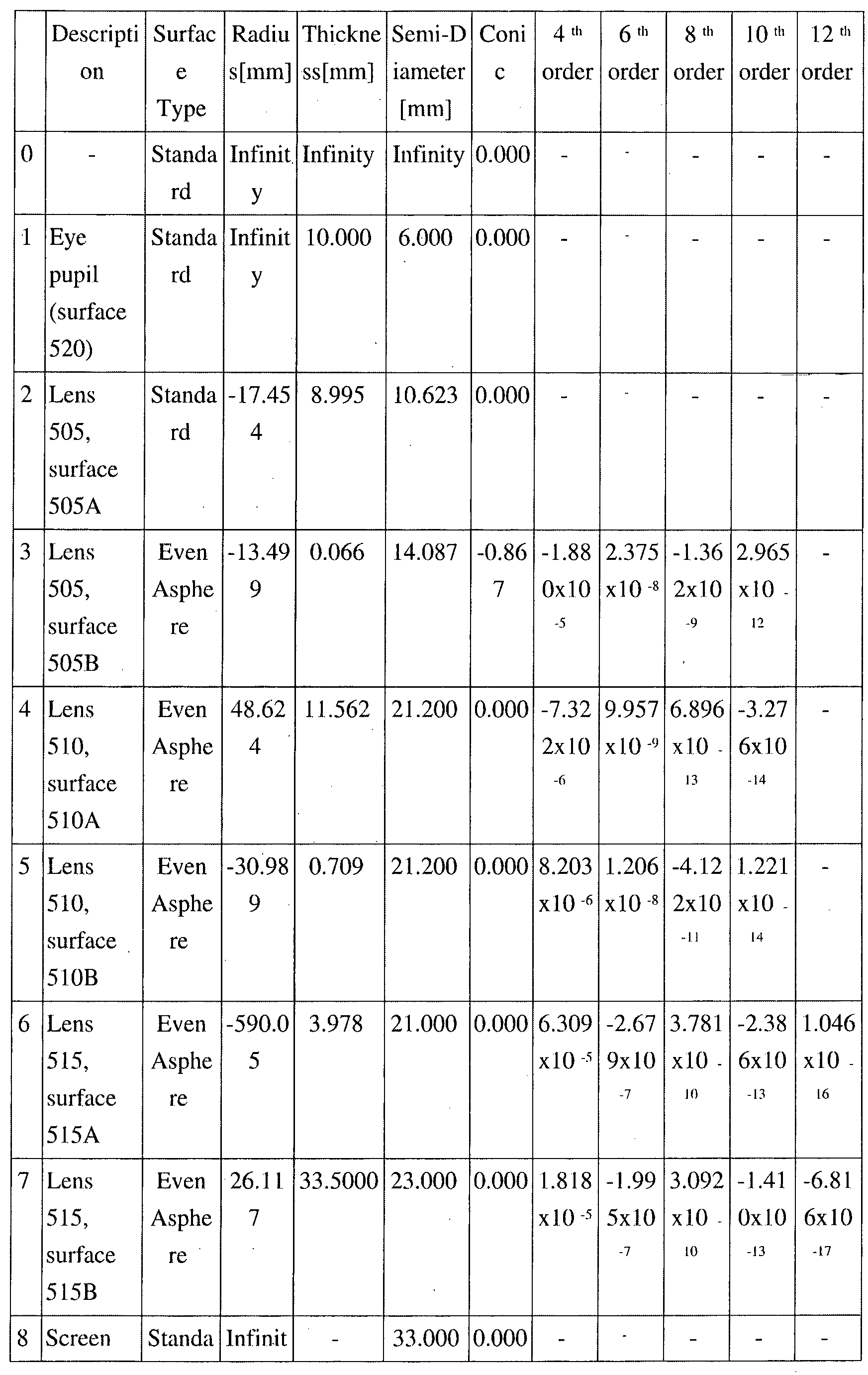
[Corrected under Rule 26, 17.10.2018]
[Corrected under Rule 26, 17.10.2018]
Table 14 illustrates a variety of additional characteristics of optical system 500. For example, Table 14 shows the overall focal length of optical system 500 (f); the focal length of each of lenses 505, 510, and 515 (f-505, f-510, f-515); the refractive index of each of lenses 505, 510, and 515 (n-505, n-510, and n-515); and the Abbe number of each of lenses 505, 510, and 515 (Vd-505, Vd-510, and Vd-515).
| f | 41 mm |
| f-505 (corresponding to f1) | 62.0 mm |
| f-510 (corresponding to f2) | 37.2 mm |
| f-515 (corresponding to f3) | -38.5 mm |
| n-505 | 1.534 |
| n-510 | 1.534 |
| n-515 | 1.642 |
| Vd-505 (corresponding to Vd1) | 56.23 |
| Vd-510 (corresponding to Vd2) | 56.23 |
| Vd-515 (corresponding to Vd3) | 22.41 |
In one or more embodiments, one or more or all of lenses 505, 510, and 515 are implemented using an optical plastic. In an example embodiment, lens 505 is implemented using Cyclic olefin copolymer (COC); lens 510 is implemented using COC; and lens 515 is implemented using OKP-1. In this example, the weight of optical system 500 is approximately 29 grams.
An optical system 500 as described in connection with FIG. 5 may be implemented to satisfy the expressions illustrated in Table 15 to provide improved optical performance.
| Expression | Value |
| OAL [mm] | 58.81 |
| BFL [mm] | 33.50 |
| D1 [mm] | 0.07 |
| D2 [mm] | 0.71 |
| f1/f | 1.51 |
| f2/f | 0.91 |
| f3/f | -0.94 |
| f1/f2 | 1.67 |
| f2/f3 | -0.97 |
| V2-V3 | 33.82 |
| OAL/f | 1.43 |
| BFL/f | 0.82 |
| r2/f | -0.33 |
| r3/f | 1.19 |
| r4/f | -0.76 |
| r5/f | -14.4 |
| D1/f | 0.00 |
| D2/f | 0.02 |
FIG. 5B illustrates lateral color aberration for optical system 500 of FIG. 5A on the screen side in micrometers. FIG. 5C illustrates field curvature and astigmatism aberrations for optical system 500 of FIG. 5A on the screen side in millimeters. FIG. 5D illustrates lateral color aberration for optical system 500 of FIG. 5A on the image side in milliradians (afocal space). FIG. 5E illustrates field curvature and astigmatism for optical system 500 of FIG. 5A on the image side in diopter units (afocal space).
FIG. 6A illustrates an example optical system 600. Optical system 600 has a weight that is approximately 42% less than the weight of optical system 100. Optical system 600 also has a FOV that is approximately up to 4% wider (110°) than the FOV of optical system 100. Optical system 600 has up to 25% larger eye box size than optical system 100. Further, optical system 600 provides reduced optical performance compared to optical system 100 of FIG. 1 as to field curvature with introduced zonal astigmatism.
In the example of FIG. 6A, lens 605 is the lens that is the most proximal lens of optical system 600 to the placement of the user's eye. Lens 605 can have positive refractive power. In this example, lens 605 has a surface 605A that is slightly convex and a surface 605B that is more sharply convex. In an embodiment, lens 605 may be a positive meniscus lens.
Table 16 provides an example of an optical prescription for optical system 600.
| Description | Surface Type | Radius[mm] | Thickness[mm] | Semi-Diameter[mm] | Conic | |
| 0 | - | Standard | Infinity | Infinity | Infinity | 0.0000 |
| 1 | Eye pupil (surface 620) | Standard | Infinity | 11.2840 | 10.000 | 0.0000 |
| 2 | |
Standard | 237.5756 | 10.5000 | 19.0000 | 0.0000 |
| 3 | |
Standard | -25.9174 | 0.2901 | 19.5000 | -0.8215 |
| 4 | |
Standard | 49.2261 | 13.0000 | 25.2800 | -0.0900 |
| 5 | |
Standard | -128.3477 | 2.3025 | 26.2817 | 16.4113 |
| 6 | |
Standard | -51.9913 | 3.0000 | 26.2817 | -3.4315 |
| 7 | |
Standard | 84.8187 | 22.1000 | 25.7817 | 0.0000 |
| 8 | Screen (surface 625) | Standard | Infinity | - | 32.0000 | 0.0000 |
Table 17 illustrates a variety of additional characteristics of optical system 600. For example, Table 17 shows the overall focal length of optical system 600 (f); the focal length of each of lenses 605, 610, and 615 (f-605, f-610, f-615); the refractive index of each of lenses 605, 610, and 615 (n-605, n-610, and n-615); and the Abbe number of each of lenses 605, 610, and 615 (Vd-605, Vd-610, and Vd-615).
| f | 40.1mm |
| f-605 (corresponding to f1) | 44.9mm |
| f-610 (corresponding to f2) | 69.2mm |
| f-615 (corresponding to f3) | -53.8mm |
| n-605 | 1.525 |
| n-610 | 1.525 |
| n-615 | 1.590 |
| Vd-605 (corresponding to Vd1) | 55.95 |
| Vd-610 (corresponding to Vd2) | 55.95 |
| Vd-615 (corresponding to Vd3) | 30.87 |
In one or more embodiments, one or more or all of lenses 605, 610, and 615 are implemented using an optical plastic. In an example embodiment, lens 605 is implemented using Zeonex 480R; lens 610 is implemented using Zeonex 480R; and lens 615 is implemented using Polystyrene. In this example, the weight of optical system 600 is approximately 43.8 grams.
An optical system 600 as described in connection with FIG. 6 may be implemented to satisfy the expressions illustrated in Table 18 to provide improved optical performance.
| Expression | Value |
| OAL [mm] | 51.12 |
| BFL [mm] | 22.10 |
| D1 [mm] | 0.29 |
| D2 [mm] | 2.30 |
| f1/f | 1.12 |
| f2/f | 1.73 |
| f3/f | -1.34 |
| f1/f2 | 0.65 |
| f2/f3 | -1.29 |
| V2-V3 | 25.08 |
| OAL/f | 1.27 |
| BFL/f | 0.55 |
| r2/f | -0.65 |
| r3/f | 1.29 |
| r4/f | -3.20 |
| r5/f | -1.30 |
| D1/f | 0.007 |
| D2/f | 0.057 |
FIG. 6B illustrates lateral color aberration for optical system 600 of FIG. 6A on the screen side in micrometers. FIG. 6C illustrates field curvature and astigmatism aberrations for optical system 600 of FIG. 6A on the screen side in millimeters. FIG. 6D illustrates lateral color aberration for optical system 600 of FIG. 6A on the image side in milliradians (afocal space). FIG. 6E illustrates field curvature and astigmatism for optical system 600 of FIG. 6A on the image side in diopter units (afocal space).
The example optical systems disclosed herein are capable of providing correction of astigmatism and field curvature resulting in total field curvature within ±1 diopter (dP) range across 70% of the full field view. Distortion may remain at approximately 35-40% at the edge of the field, but may be corrected in software using a distortion transformation of the opposite sign. The example optical systems further are capable of providing improved longitudinal spherical aberration correction across the pupil with less color aberration. For example, lateral color of the example optical systems is corrected to less than one (1) milliradian (which can correspond to a single pixel on 518 ppi display observed through a 35 mm focal length VR set).
The focus of the example optical systems described herein may be adjusted to compensate for the optical prescription of an individual user eye (e.g., single vision SPHERE factor, to correct for myopia or hyperopia, while astigmatism/CYLINDER prescription may not be not corrected). Compensation for optical prescription of a user may be accomplished by moving the optical system, for each eye, away or toward the screen(s) to achieve the best focus for the user's eye while keeping optical aberrations under control. In one aspect, the optical system for each eye may be moved independently of the other.
The examples described herein exhibit variation in lens size/thickness, relative separation between lenses, and/or distance to the screen(s). Increased size of the lenses and movement of the lenses closer to the screen(s) usually provides better performance, but at the cost of increased weight. The example optical systems disclosed herein provide a balance with three optical lenses and a weight ranging from less than approximately 30 grams to an upper threshold of approximately 74.9 grams when using optical plastics as described.
It should be appreciated that the particular materials described herein for implementing lenses are provided for purposes of example only. Other suitable optical plastics may be used. For purposes of illustration, for the optical system embodiments described herein, example substitutes for OKP-1 may include, but are not limited to, OKP4, OKP4HT, Polystyrene, and Polycarbonate. Other suitable substitutes for OKP-1 may include flint type materials with a low Abbe number around 30. Example substitutes for COC within the optical system embodiments described herein can include, but are not limited to, polymethyl methacrylate (PMMA), acrylic, 330R, 480R, and Zeonex E48R. Other suitable substitutes for COC may include crown type materials having an index of refraction around 1.5 and an Abbe number close to 56. For example, in the various example optical systems described herein, the first two lenses are crowns, while the third lens is flint. Embodiments utilizing plastics as described may be manufactured using injection molding techniques.
In alternative example embodiments, one or more or each of the lenses may be implemented as an equivalent or substantially equivalent Fresnel lens.
In one or more embodiments, the lenses implemented within each of the example optical systems described herein may be implemented to include a flange. The flange, for example, may aid in mounting the lenses within a suitable housing.
In one or more embodiments, the lenses included in the optical systems described herein may be cropped. For example, the lenses may be cropped, e.g., trimmed, along the edge of each of the lenses that is close, or closest, to the user's nose when the optical systems are positioned within a VR headset. By cropping the lenses, additional room for the user's nose is provided when the optical systems are incorporated into the VR headset. The lenses also may be cropped along the edge of each lens that is placed next to another lens in a tiled fashion. Thus, the cropped lenses are no longer round or cylindrical across the perimeter. It should be appreciated that cropping the lenses as described to better accommodate the user's nose and/or placement in a tiled fashion does not have an effect upon the optical performance of the optical systems.
In one or more alternative embodiments, one or more optical windows may be added. For example, a flat window may be added at the image side, at the object side, or both of the optical systems described herein. The window(s) may be made of glass or plastic. For example, an optical window may be placed immediately to the left of the lens closest to the user's eye. An optical window may be placed immediately to the right of the lens closest to the screen(s). The optical windows provide protection for the optics. Further, optical windows may provide a surface that is easier to dust, wipe, or otherwise clean. The optical window(s) may be added without modifying the optical prescriptions and/or optical characteristics (e.g., the expressions) of the various example embodiments described.
In one or more embodiments, an optical window on the user eye side of the optical system may be added that does modify the optical characteristics of the example embodiments described herein. For example, the optical window may be fabricated to implement a user's eye prescription. The optical window, for example, may be configured to mount, e.g., snap, on or into the VR headset so that the optical window with the user's prescription is closer to the user's eye than the first lens of the optical system located on the image side. By incorporating the user's eye prescription into an optical window on the user eye side of the optical system, the user need not wear eye glasses when using the VR headset.
FIG. 7A illustrates a forward facing view of a typical human visual system field of view (FOV) 700, which includes a FOV 705 of a left eye and a FOV 710 of a right eye, the FOV 705 and FOV 710 overlapping in a central region 715 of the FOV 700. The typical human FOV 700 typically extends horizontally a range 720 of about 200°-220° and extends vertically a range 725 of about 120°. An ordinary VR headset typically presents to a user a substantially round FOV 730 having a diameter extending a range of about 90° to 100° within the central region 715 of the FOV 700.
FIG. 7B illustrates a top view of the typical human visual system FOV 700. A maximum amount of stereo vision for the typical user 750 can be about 114° whereas, using peripheral vision, the typical user 750 can see FOV up to a range of about 200°-220°.
FIG. 8 illustrates an example of a near eye display system 800 in accordance with arrangements described herein. The near eye display system 800 can be, for example, part of a head mountable VR headset. The near eye display system 800 can include a plurality of displays, for example a display 805, a display 810 and a display 815. The displays 805, 810 can be configured to present images to a left eye of the user 750 and the displays 805, 815 can be configured to present images to a right eye of the user 750. For example, a viewing surface 806 (i.e., screen) of the display 805 via which images/video are presented can be normal to a direction 825 in which the user 750 is facing while wearing a VR headset including the near eye display system 800. A viewing surface 811 (i.e., screen) of the display 810 can extend outward from, or near, an edge 830 of the display 805 at a horizontal angle 835 opposite the direction 825. The angle 835 can be in a range of about 120° to about 140°. For example, the angle 845 can be approximately 120°, 130° or 140°. A viewing surface 816 (i.e., screen) of the display 815 can extend outward from, or near, an edge 840 of the display 805, which is opposite of edge 830, at a horizontal angle 845 opposite the direction 825. The angle 845 can be in a range of about 120° to about 140°. For example, the angle 845 can be approximately 120°, 130° or 140°.
The near eye display system 800 also can include a plurality of triplet lenses, for example a triplet lens 850, a triplet lens 855, a triplet lens 860 and a triplet lens 865. The triplet lenses 850-865 can be arranged in a tile fashion where they are tiled with respect to one another, extending horizontally in front of the displays 805-815. The triplet lenses 850, 855 can be associated with a left eye of the user 750, and the triplet lenses 860, 865 can be associated with a right eye of the user 750. In one non-limiting arrangement, the triplet lenses 850-865 can be implemented in accordance with the triplet lens 118 of FIG. 1 and/or in accordance with the triplet lens 218 of FIG. 2.
The triplet lenses 850, 860 can be paired with the display 805. In this regard, the triplet lens 850 can be positioned between the user's left eye and the display 805, and can be configured to face the display 805. The focal characteristics of the triplet lens 850 can be selected based on its positions relative the user's left eye and the display 805. The triplet lens 860 can be positioned between the user's right eye and the display 805, and can be configured to face the display 805. The focal characteristics of the triplet lens 860 can be selected based on its positions relative the user's right eye and the display 805. The triplet lens 855 can be paired with the display 810, positioned between the user's left eye and the display 810, and can be configured to face the display 810. The focal characteristics of the triplet lens 855 can be selected based on its positions relative the user's left eye and the display 810. The triplet lens 865 can be paired with the display 815, positioned between the user's right eye and the display 815, and can be configured to face the display 815. The focal characteristics of the triplet lens 865 can be selected based on its positions relative the user's right eye and the display 815.
The triplet lens 850 and the triplet lens 855 can be tiled with respect to one another, forming a tile angle between their respective optical paths. Similarly, the triplet lens 860 and the triplet lens 865 can be tiled with respect to one another, forming a tile angle between their respective optical paths. The tile angle between the triplet lens 850 and the triplet lens 855 can be the same, or substantially the same, as the angle 835. The tile angle between the triplet lens 860 and the triplet lens 865 can be the same, or substantially the same, as the angle 845.
In one non-limiting arrangement, the near eye display system 800 can use a single lens, or two lenses, in place of the triplet lens 855 and/or can use a single lens, or two lenses, in place of the triplet lens 865. In another non-limiting arrangement, the near eye display system 800 can use a single lens, or two lenses, in place of the triplet lens 850 and/or can use a single lens, or two lenses, in place of the triplet lens 860. In yet another non-limiting arrangement, the near eye display system 800 can use a single lens, or two lenses, in place of the triplet lens 850, can use a single lens, or two lenses, in place of the triplet lens 855, can use a single lens, or two lenses, in place of the triplet lens 860 and/or can use a single lens, or two lenses, in place of the triplet lens 865. Still, the near eye display system 800 can use any number of lenses in place of the triplet lenses 850-865, and the present arrangements are not limited in this regard.
FIG. 9 illustrates another example of a near eye display system 900. The near eye display system 900 is substantially similar to near eye display system 800 of FIG. 8, except that two displays 905, 910 are used in lieu of the display 805. In this arrangement, the displays 905, 910 can be configured to present images to the left eye of the user 750, and the displays 910, 815 can be configured to present images to the right eye of the user 750. Respective viewing surfaces (i.e., screens) 906, 911 of the displays 905, 910 can be normal to the direction 825. Further, the angle 835 between the display 905 and the display 810, and the angle 845 between the display 910 and the display 815, can be in ranges of about 120° to about 140°. For example, the angles 835, 845 each can be approximately 120°, 130° or 140°.
In this arrangement, the triplet lens 850 can be paired with the display 905, positioned between the user's left eye and the display 905, and can be configured to face the display 905. The focal characteristics of the triplet lens 850 can be selected based on its positions relative the user's left eye and the display 905. The triplet lens 860 can be paired with the display 910, positioned between the user's right eye and the display 910, and can be configured to face the display 910. The focal characteristics of the triplet lens 860 can be selected based on its positions relative the user's right eye and the display 910. The triplet lens 855 can be paired with the display 810, positioned between the user's left eye and the display 810, and can be configured to face the display 810. The focal characteristics of the triplet lens 855 can be selected based on its positions relative the user's left eye and the display 810. The triplet lens 865 can be paired with the display 815, positioned between the user's right eye and the display 815, and can be configured to face the display 815. The focal characteristics of the triplet lens 865 can be selected based on its positions relative the user's right eye and the display 815.
In one non-limiting arrangement, the displays 810, 815, 905, 910 and triplet lenses 850, 855, 860, 865 can be configured to move horizontally, along line 920 parallel to the displays 905, 910. Such configuration can allow for adjustability of displays 810, 815, 905, 910 and triplet lenses 850, 855, 860, 865 to accommodate different pupillary distances of users, and adjust to different pupillary distances of users using the near eye display system 900. In illustration, horizontal positioning of the and triplet lenses 850, 855, 860, 865 can be adjusted for the pupillary distance of the user 750 to place the focal points of the triplet lenses 850, 855 at the appropriate position for the user's left eye and to place the focal points of the triplet lenses 860, 865 at the appropriate position for the user's right eye. In this arrangement, the triplet lenses 850, 855 can be fixed relative to the displays 810, 905, and the triplet lenses 860, 865 can be fixed relative to the displays 815, 910. Thus, the triplet lenses 850, 855 and displays 810, 905 can be moved together horizontally along the line 920, and the triplet lenses 860, 865 and displays 815, 910 can be moved together horizontally along the line 920. The near eye display system 900 can include one or more structures, such as sliding mechanisms, to which the displays 810, 815, 905, 910 and triplet lenses 850, 855, 860, 865 are attached to facilitate the adjustability.
FIG. 10 illustrates another example of a near eye display system 1000. The near eye display system 1000 is substantially similar to near eye display system 800 of FIG. 8 or the near eye system 900 of FIG. 9, except that the displays 810, 815 and triplet lenses 850, 855, 860, 865 can be configured to move horizontally, along line 1005 parallel to the display 805 (or the displays 905, 910), while the display 805 (or the displays 905, 910) can remain in a fixed position. Such configuration can allow for adjustability of displays 810, 815 and triplet lenses 850, 855, 860, 865 to accommodate different pupillary distances of users, and adjust for different pupillary distances of users using the near eye display system 1000. In illustration, horizontal positioning of the and triplet lenses 850, 855, 860, 865 can be adjusted for the pupillary distance of the user 750 to place the focal points of the triplet lenses 850, 855 at the appropriate position for the user's left eye and to place the focal points of the triplet lenses 860, 865 at the appropriate position for the user's right eye.
The displays 810, 815 can be inset with respect to the display 805 (or the displays 905, 910), allowing the displays 810, 815 to be adjusted horizontally without interference from the display 805. In illustration, inner edges 1010, 1015 of the respective displays 810, 815 can be inset (e.g., in the direction of the user 750) at least a threshold distance 1020 with respect to edges 830, 840 of the display 805 (or the displays 905, 910). The threshold distance 1020 is a distance that will allow the displays 810, 815 to move horizontally without the display 805 (or the displays 905, 910) interfering with such movement, thus allowing the displays 810, 815 to at least partially overlap the display 805 (or the displays 905, 910). The threshold distance can be, for example, 0.5 mm, 1.0 mm, 1.5 mm, etc.
The position of the triplet lenses 850, 855 can be fixed relative to the display 810 and move with the display 810. Similarly, the position of triplet lenses 860, 865 can be fixed relative to the display 815 and move with the display 815. Thus, the triplet lenses 850, 855 and display 810 can be moved together horizontally along the line 920, and the triplet lenses 860, 865 and display 815 can be moved together horizontally along the line 920. The near eye display system 900 can include one or more structures, such as sliding mechanisms, to which the displays 810, 815 and triplet lenses 850, 855, 860, 865 are attached to facilitate the adjustability.
The near eye display system 1000 also can include one or more sensors (not shown) that detect the position of the triplet lenses 850, 860 relative to the viewing surface (i.e., screen) 806 of the display 805 (or the viewing surfaces 906, 911 of the displays 905, 910). The near eye display system 1000 also can include computer program code, executable by a processor of the near eye display system 1000, that receives sensor data from the sensors and, based on the sensor data, adjusts images/video presented on the viewing surface 806 for the position of the triplet lenses 850, 860. In illustration, the processor can locate images/video, which are presented by the display 805 to the user's left eye, to be presented at a location on the display 805 in front of the triplet lens 850 given the current position of the triplet lens 850. Similarly, the processor can locate images/video, which are presented by the display 805 to the user's right eye, to be presented at a location on the display 805 in front of the triplet lens 860 given the current position of the triplet lens 850.
FIG. 11 is a perspective view illustrating an example of the tiled triplet lenses 850, 855 of the near eye display system 800 of FIG. 8. The triplet lens 850 can be configured as previously described with reference any of FIGs. 1-5, and can include a lens 1105, a lens 1110 and a lens 1115. The triplet lens 855 can be configured as previously described with reference to any of FIGs. 1-5, and can include a lens 1120, a lens 1125 and a lens 1130.
In one non-limiting arrangement, the lens 1115 and the lens 1130 each can be blackened around their respective perimeters 1135, 1140. For example, a dark (e.g., black) paint or other suitable light absorbing material can be applied to the respective perimeters. The paint or other suitable light absorbing material can serve to prevent ghost reflections and stray light around portions of the field of view provided by the respective triplet lenses 850, 855 by mitigating total internal reflection (TIR) of light by the respective perimeters 1135, 1140.
Further, a baffle 1145 can be positioned between the lens 1115 and the lens 1130. The baffle 1145 be made of, for example, a material such as plastic or metal with non-reflecting roughened surface. The material can be dark (e.g., black) or coated with a dark paint or other suitable coating. The baffle 1145 can control stray light and prevent crosstalk between light signals emanated by the screens 805 (or 905) and 810 through respective triplet lenses 850, 855.
The triplet lenses 860, 865 can be configured in a manner similar to that described above for the triplet lenses 850, 855.
FIG. 12 is a top cross-section view illustrating an example of the tiled triplet lenses 850, 855. In this example, the triplet lenses 850, 855 can be configured as described for the optical system 600 of FIG. 6. The triplet lenses 860, 865 of FIG. 8 can be configured in a similar manner. The triplet lenses 850, 855 can be positioned to form a horizontal tile angle 1205 between their respective optical path centerlines 1210, 1215. The optical path centerline 1210 can be an imaginary line extending through the centers of curvature of the lenses 1105-1115, and the optical path centerline 1215 can be an imaginary line extending through the centers of curvature of the lenses 1120-1130. Further, the optical path centerline 1210 can be normal to the viewing surface 806 of the display 805 (or the viewing surface 906 of the display 905) and the optical path centerline 1215 can be normal to the viewing surface 811 of the display 810. The tile angle 1205 can be complementary to the horizontal angle 835 of FIG. 8, wherein the sum of the tile angle 1205 and the horizontal angle 835 approximately equal 180°. In this regard, the angle 1205 can be in a range of about 30° to about 75°. For example, the angle 1205 can be approximately 50°, 55° or 60°.
In one non-limiting arrangement, the lenses 1105-1130 can be individually molded and/or ground to shape, and attached together to form the triplet lenses 850, 855. In illustration, after the lenses 1105-1130 are molded and/or ground to shape, the lenses can be cut or cropped (e.g., trimmed) along a line defined by imaginary line 1220. An angle 1225 of the cut/trim of the lenses 1105-1115, and an angle 1230 of the cut/trim of the lenses 1120-1130, each can be one-half of the tile angle 1205. For example, if the tile angle 1205 is 50°, the angles 1225, 1230 each can be 25°. Thus, when the lenses 1105-1130 are attached together, the tile angle 1205 between the respective optical path centerlines 1210, 1215 will result. The lenses 1105-1130 can be attached a suitable adhesive or attached using a physical structure within the near eye display system 800, 900, 1000 that holds the respective lenses 1105-1130 in appropriate positions.
In another non-limiting arrangement, the lenses 1105, 1120 can be molded as a single element, and the lenses 1110, 1125 can be molded as a single element. Further, the lenses 1115, 1130 can be molded as a single element. In such an arrangement, the baffle 1145, if used, can be inserted in the mold between the lenses 1115, 1130 during the molding process.
As noted, the lenses 1105-1125 can be implemented using optical plastic and/or optical glass. Further, the combined total weight of the triplet lenses 850, 855 can be equal to or less than 130 g, 100 g, 75 g or 50 g, depending on the types of lenses used in the triplet lenses 850, 855 and the material from which the lenses are made. Thus, the near eye display system 800 can be relatively light weight, benefiting comfort of wearing an apparatus (e.g., a VR headset) that incorporates the near eye display system 800.
FIG. 13 illustrates an example of a field of view (FOV) 1300 provided by the near eye display system 800, 900, 1000 of FIGs. 8-12 using tiled triplet lenses 850-865. The FOV 1300 can be accomplished using tiled triplet lenses 850-865 designed in accordance with the triplet lenses 118, 218, 318, 418, 518 and/or 618 of FIGs. 1-6. Due to use of a plurality of displays 805-815 (or 810, 815, 905, 910) and a plurality of triplet lenses 850-865, the FOV 1300 can extend horizontally a range 1305 and extend vertically a range 1310. The horizontal range 1305 can be greater than 180°, greater than 190°, greater than 200°, or greater than 210°. The vertical range 1310 can be greater than 80°, greater than 90°, greater than 100° or greater than 110°. Thus, in comparison to display systems used in conventional VR headsets, the near eye display system 800 can provide a much greater FOV. Moreover, the near eye display system 800, 900, 1000 can do so without significant field curvature aberrations, and provide high image quality across the entire FOV 1300. In this regard, the use of multiple displays 805-815 (or 810, 815, 905, 910) can overcome the FOV-resolution invariant exhibited by single display VR headsets.
FIGs. 14A-14F illustrate example light ray traces for light provided by the near eye display system 800, 900, 1000 to an eye of a user at various FOV angles using tiled triplet lenses 850, 855. In these examples, the triplet lenses 850, 855 can be implemented in accordance with the design of the triplet lens 118 of FIG. 1, and the eye of the user is the left eye. The near eye display system 800, 900, 1000 can present a similar FOV for the right eye using tiled lens triplets 860, 865.
Specifically, FIG. 14A illustrates examples light ray traces 1400, 1405 provided by the near eye display system 800, 900, 1000 to the left eye of a user via the triplet lenses 850, 855 at a FOV angle of 0°. The light ray traces 1400 correspond to light emanating from the display 805 (or 905), and the light ray traces 1405 correspond to light emanating from the display 810.
FIG. 14B illustrates examples light ray traces 1410, 1415 provided by the near eye display system 800, 900, 1000 to the left eye of the user via the triplet lenses 850, 855 at a FOV angle of 20°. The light ray traces 1410 correspond to light emanating from the display 805 (or 905), and the light ray traces 1415 correspond to light emanating from the display 810.
FIG. 14C illustrates examples light ray traces 1420, 1425 provided by the near eye display system 800, 900, 1000 to the user via the triplet lenses 850, 855 at a FOV angle of 40°. The light ray traces 1420 correspond to light emanating from the display 805 (or 905), and the light ray traces 1425 correspond to light emanating from the display 810.
FIG. 14D illustrates examples light ray traces 1430 provided by the near eye display system 800, 900, 1000 to the left eye of the user via the triplet lenses 850, 855 at a FOV angle of 60°. The light ray traces 1430 correspond to light emanating from the display 810. The display 805 (or 905) need not contribute light for images/video provided at the 60° FOV angle.
FIG. 14E illustrates examples light ray traces 1440 provided by the near eye display system 800, 900, 1000 to the left eye of the user via the triplet lenses 850, 855 at a FOV angle of 80°. The light ray traces 1440 correspond to light emanating from the display 810. The display 805 (or 905) need not contribute light for images/video provided at the 80° FOV angle.
FIG. 14F illustrates examples light ray traces 1450 provided by the near eye display system 800, 900, 1000 to the left eye of the user via the triplet lenses 850, 855 at a FOV angle of 100° The light ray traces 1450 correspond to light emanating from the display 810. The display 805 (or 905) need not contribute light for images/video provided at the 100° FOV angle.
FIG. 14G illustrates field curvature 1460 for the FOV of FIGs. 14A-14F. The field curvature 1460 is for the FOV as presented to the left eye of the user, which can have a maximum eye rotation of about -35° to about 35°. As can be seen in the field curvature 1460, the field curvature is low for FOV angles from about -50° to about 100°. The left eye can detect the FOV over this range using peripheral vision. A field curvature for the FOV as presented to the right eye will be similar, extending from about -100° to about 50°. Collectively, using both eyes, the user can have a FOV that extends at least 200° with a very small amount of field curvature. The field curvature 1460 can be accomplished using triplet lenses 850, 855 implemented in accordance with the design of the triplet lens 118 of FIG. 1.
FIG. 15 illustrates a top cross-section view of another example of the tiled triplet lenses 850, 855. In this example, the triplet lenses 850, 855 can be configured as described for the optical system 600 of FIG. 6. In this arrangement, the lenses 1105, 1110 and/or 1115, and the lenses 1120, 1125 and/or 1130 can have a reduced depth in comparison to the tiled triplet lenses 850, 855 previously described, for example as represented by depth 1505 of lens 1110. For example, a space 1510 between a surface 1515 of the lens 1110 and a surface 1520 of the lens 1115 may be provided. If the depth of one or more of the lenses 1105, 1110 and/or 1115, and/or of the lenses 1120, 1125 and/or 1130, is reduced, the optical prescription of the lenses 1105-1115 and/or 1120-1130 can be changed accordingly to minimize the field curvature in the FOV using those lenses 1105-1130. This can result in less material being provided to make the lenses 1105-1130, and thus less weight for the triplet lenses 850-855. The weight of the triplet lenses 860-865 can be reduced in a similar manner.
FIG. 16A illustrates examples light ray traces 1600 provided by the near eye display system to an eye (e.g., a left eye) of a user using reduced weight tiled triplet lenses 850, 855 over FOV angles of -50° to 100° In this example, the triplet lenses 850, 855 can be implemented in accordance with the design of the triplet lens 618 of FIG. 6, which is lighter in weight than the triplet lenses implemented in accordance with the design of the triplet lenses 118, 218 of FIGs. 1 and 2.
FIG. 16B illustrates field curvature for the FOV of FIG. 16A. The field curvature 1610 is for the FOV as presented to the left eye of the user, which can have a maximum eye rotation of about -35° to about 35°. As can be seen in the field curvature 1610, the field curvature can vary over FOV angles from about -50° to about 100°. The left eye can detect the FOV over this range using peripheral vision. A field curvature for the FOV as presented to the right eye will be similar, extending from about -100° to about 50°. Collectively, using both eyes, the user can have a FOV that extends at least 200° in accordance with the field curvature 1610. The field curvature 1610 may not be as smooth as the field curvature 1460 of FIG. 14G, but may be acceptable given the weight savings provided by this particular arrangement.
FIG. 17 is an example VR headset 1700. The VR headset 1700 can include the near eye display system 800 of FIG. 8. A VR headset including the near eye display system 900 of FIG. 9, or a VR headset including the near eye display system 1000 of FIG. 10, can be configured in a similar manner.
The VR Headset 1700 is adapted to be worn by a user and is an example of a head-mountable assembly. The VR Headset 1700 may include a frame 1705. A strap 1710 may be coupled to frame 1705. A user may wear the VR Headset 1700 so that the user's eyes gaze through triplet lenses 850, 860 toward the display 805, in particular the viewing surface 806 (i.e., screen) of the display 805, gaze through the triplet lens 855 toward the display 810, in particular the viewing surface 811 (i.e., screen) of the display 810, and gaze through the triplet lens 865 toward the display 815, in particular the viewing surface 816 (i.e., screen) of the display 815.
In one aspect, the frame 1705 can be adapted to include a display mount 1715. The display mount 1715 can be configured to receive the displays 805-815. The display mount 1715 may be shaped to cooperatively engage the displays 805-815. Further, the display mount 1715 may include one or more fastening or locking mechanisms adapted to secure the displays 805-815 in place. For example, the display mount 1715 may include latches, straps, etc. Though not shown, the frame 1705 may include one or more doors or hatches that may be closed to cover the exterior surface (back side opposite the screen sides) of displays 805-815 so that displays 805-815 are secured inside of the frame 1705 once mounted in the display mount 1715. Each display 805-815 can be a component of respective display device, for example a smart phone, a smart phone accessory, or a VR component.
In another aspect, each display 805-815 may be implemented as any of a variety of display devices that include a screen. Example implementations of a display device include, but are not limited to, a cell phone, a mobile phone, a portable computing and/or communication device, standalone screens, etc. The screens 806, 811, 816 can be capable of stereoscopic operation. In one example, one or more of the screens 806, 811, 816 may be implemented as an LCD screen. In another example, one or more of the screens 806, 811, 816 may be implemented as an OLED screen. Further, in another example, the screens 806, 811, 816 may be configured to display images up to and including various sizes described herein depending upon the particular optical system utilized and/or any scaling of such system that may be implemented. The screen 806 can face the triplet lenses 850, 860 so that a user looking through triplet lenses 850, 860 may view images displayed upon screen 806. The screen 811 can face the triplet lens 855 so that a user looking through triplet lens 855 may view images displayed upon screen 811. The screen 816 can face the triplet lens 865 so that a user looking through triplet lens 865 may view images displayed upon screen 816.
In another embodiment, the VR Headset 1700 may include screens that are integrated therein and capable of stereoscopic operation. In that case, for example, the screens may not be removable or part of another removable device. Appreciably, where the VR Headset 1700 includes integrated, non-removable screens, the VR Headset 1700 can be adapted to include the necessary mounting structures, fasteners, and/or adhesives to secure the screens. The screens may be implemented substantially as described within this disclosure. The screens may be implemented using any of a variety of different technologies including, but not limited to, those noted herein.
Each of triplet lenses 855-865 may be implemented as a module or assembly capable of receiving and securely holding any of the optical systems described herein. It should be appreciated that triplet lenses 855-865 can be, but need not be, matched. In other words, the same optical system implementation used for the triplet lens 850 may be used for the triplet lens 860 and, optionally, may also be used for the triplet lenses 855, 865. The position of triplet lenses 850-865 may be moved closer or farther from the user's eye and/or displays 805-815. In one arrangement, in lieu of the triplet lens 855, the VR headset 1700 can include a single lens or two lenses in a double lens configuration. Further, in lieu of the triplet lens 865, the VR headset 1700 can include a single lens or two lenses in a double lens configuration.
The frame 1705 may also include processing and control circuitry 1715. Examples of the processing and control circuitry 1715 may include, but are not limited to, motion detection systems, control systems, input devices, interface circuitry capable of coupling (e.g., physically and/or electrically) with the displays 810-815 (or other screen or screens), audio circuitry and/or audio interface(s), wireless transceivers, interface circuitry for coupling to other systems external to the VR headset 1700, and so forth. For example, the processing and control circuitry 1715 may include audio jacks, communication ports, and so forth. The frame 1705 may further include a power source 1720 such as a battery or batteries. The batter(ies) may be rechargeable. In another example, the power source 1720 may be a power adapter interface, a receptacle, etc. to couple an external power source such as a power adapter to the VR Headset 1700 and/or a rechargeable battery included therein.
FIG. 18 illustrates an example method 1800 of implementing an optical system in accordance with the example embodiments described herein, for example to form a triplet lens. In one or more embodiments, method 1800 may be implemented by locating the various lenses as described within a lens mounting assembly adapted to secure the lenses positioned as described. In one or more other embodiments, aspects of method 1800 may be implemented using an injection molding process. For example, using an injection molding process, each of the three lenses may be fabricated and positioned as described within a mounting assembly or module. In another example, conditioned upon the ability of 3D printing technology to generate a surface finish of sufficient optical quality, the optical system may be fabricated using a 3D printing technology. In any case, lenses of the optical system may be provided as described below.
In block 1805, a first lens having a positive refractive power is located at a position at an image side of an optical path. For example, the first lens may be most proximal to the image side of the optical path. In block 1810, a second lens having a positive refractive power is provided. The second lens is positioned relative to the first lens. For example, the second lens may be located in a position that is adjacent to the first lens. In block 1815, a third lens having a negative refractive power is located at a position at an object side of the optical path. For example, the third lens may be most proximal to the object side of the optical path. In an aspect, the second lens is located between the first lens and the third lens. Further, the first lens, the second lens, and the third lens form the optical path with the object side facing a screen and the image side adapted to provide an image from the screen to a user.
In an aspect, the lenses of the optical system may be cropped so as to better accommodate the user's nose and/or to accommodate being placed immediately next to other lenses in a tiled fashion when the optical system(s) are incorporated into a VR headset. In one aspect, the lenses may be cropped after fabrication. In another aspect, the lenses may be fabricated in the cropped shape so that post processing of the lenses, e.g., cropping of the lenses, need not be performed.
In an aspect, the optical system is configured to satisfy the expression 0.8 < f1/f <2.2 and the expression 0.8 < f2/f <1.89.
In another aspect, the optical system is configured to satisfy the expression -1.0 < f3/f < -0.4 and the expression 0.4 < f1/f2 < 2.0.
In another aspect, the optical system is configured to satisfy the expression -3.0 < f2/f3 < -0.8 and the expression |Vd2-Vd3|>24.
In another aspect, the optical system is configured to satisfy the expression 1.0< OAL/f < 1.8 and the expression 0.0 < D1/f < 0.2.
In another aspect, the optical system is configured to satisfy the expression 0.2 < BFL/f < 0.9 and the expression 0.0 < D2/f < 0.4.
In another aspect, the optical system is configured to satisfy the expression -1.0 < r2/f < -0.2 and the expression 0.5 < r3/f < 2.5.
In another aspect, the optical system is configured to satisfy the expression -5.0 < r4/f < -0.5 and the expression -20 < r5/f < -0.5.
The foregoing expressions relating to method 1800 are obtained from expressions of Tables 1-18 described herein. It should be appreciated that while the examples provided herein combine certain ones of the expressions, the example embodiments described herein are provided for purposes of illustration. Optical systems as described herein may satisfy any combination of one or more (e.g., any subset of expressions of Tables 1-18) or all of expressions of Tables 1-18.
In another aspect, the optical system corrects astigmatism, field curvature, and/or lateral color. In another aspect, the optical system corrects at least one of a group of aberrations including astigmatism and field curvature; or lateral color.
In still another aspect, the optical system may be provided as an eyepiece included in a VR head-mountable assembly, wherein the head-mountable assembly includes one or more screens or is adapted to receive a display device having one or more screens. The eyepiece may be integrated, e.g., not removable, with the VR head-mount assembly. In another aspect, the eyepiece(s) may be provided as part of a removable lens module. As discussed, the display device may be a mobile phone.
FIG. 19 illustrates an example method 1900 of implementing a near eye display system in accordance with the example embodiments described herein. At step 1905, a first triplet lens can be configured in a tile fashion to be associated with a left eye. At step 1910, a second triplet lens can be configured in the tile fashion to be associated with a right eye. At step 1915, a third triplet lens (or a third lens), can be configured in the tile fashion to be associated with the left eye. At step 1920, a fourth triplet lens (or a fourth lens) can be configured in the tile fashion to be associated with the right eye.
At step 1925, a multiple display system can be paired with the lenses. The multiple display system can include, for example, a first display, a second display and a third display. The first and second triplet lenses can be configured to face the first display. The third triplet lens can be configured to face the second display, and the fourth triplet lens can be configured to face the third display. In another example, the multiple display system can include a first display, a second display, a third display and a fourth display. The first triplet lens can be configured to face the first display, the second triplet lens can be configured to face the second display, the third triplet lens can be configured to face the third display, and the fourth triplet lens can be configured to face the fourth display.
The terminology used herein is for the purpose of describing particular embodiments only and is not intended to be limiting. Notwithstanding, several definitions that apply throughout this document now will be presented.
As defined herein, the singular forms "a," "an," and "the" are intended to include the plural forms as well, unless the context clearly indicates otherwise. As defined herein, the terms "at least one," "one or more," and "and/or," are open-ended expressions that are both conjunctive and disjunctive in operation unless explicitly stated otherwise. For example, each of the expressions "at least one of A, B, and C," "at least one of A, B, or C," "one or more of A, B, and C," "one or more of A, B, or C," and "A, B, and/or C" means A alone, B alone, C alone, A and B together, A and C together, B and C together, or A, B, and C together.
As defined herein, the terms "one embodiment," "an embodiment," "one or more embodiments," or similar language mean that a particular feature, structure, or characteristic described in connection with the embodiment is included in at least one embodiment described within this disclosure. Thus, appearances of the phrases "in one embodiment," "in an embodiment," "one or more embodiments," and similar language throughout this disclosure may, but do not necessarily, all refer to the same embodiment. The terms "embodiment" and "arrangement" are used interchangeably within this disclosure.
The terms first, second, etc. may be used herein to describe various elements. These elements should not be limited by these terms, as these terms are only used to distinguish one element from another unless stated otherwise or the context clearly indicates otherwise.
The corresponding structures, materials, acts, and equivalents of all means or step plus function elements that may be found in the claims below are intended to include any structure, material, or act for performing the function in combination with other claimed elements as specifically claimed.
The description of the embodiments provided herein is for purposes of illustration and is not intended to be exhaustive or limited to the form and examples disclosed. The terminology used herein was chosen to explain the principles of the inventive arrangements, the practical application or technical improvement over technologies found in the marketplace, and/or to enable others of ordinary skill in the art to understand the embodiments disclosed herein. Modifications and variations may be apparent to those of ordinary skill in the art without departing from the scope and spirit of the embodiments provided herein. Accordingly, reference should be made to the following claims, rather than to the foregoing disclosure, as indicating the scope of such features and implementations.
Claims (15)
- A near eye display system comprising:a first triplet lens arranged in a tile fashion and configured to be associated with a left eye;a second triplet lens arranged in the tile fashion and configured to be associated with a right eye; anda multiple display system paired with the first triplet lens and the second triplet lens.
- The near eye display system of claim 1, further comprising:a third triplet lens arranged in the tile fashion and configured to be associated with the left eye; anda fourth triplet lens arranged in the tile fashion and configured to be associated with the right eye;wherein the multiple display system further is paired with the third triplet lens and the fourth triplet lens.
- The near eye display system of claim 2, wherein:the multiple display system comprises a first display, a second display and a third display;the first triplet lens is configured to face the first display;the second triplet lens is configured to face the first display;the third triplet lens is configured to face the second display;the fourth triplet lens is configured to face the third display;the first triplet lens and the third triplet lens are tiled with respect to one another forming an angle of at least 30° between their respective optical path centerlines; andthe second triplet lens and the fourth triplet lens are tiled with respect to one another forming an angle of at least 30° between their respective optical path centerlines.
- The near eye display system of claim 3, wherein:the first triplet lens and the third triplet lens are fixed relative to the second display, and the first triplet lens, the third triplet lens and the second display are configured to move horizontally parallel to the first display.
- The near eye display system of claim 2, wherein:the multiple display system comprises a first display, a second display, a third display and a fourth display;the first triplet lens is configured to face the first display;the second triplet lens is configured to face the second display;the third triplet lens is configured to face the third display;the fourth triplet lens is configured to face the fourth display;the first triplet lens and the third triplet lens are tiled with respect to one another forming an angle of at least 30° between their respective optical path centerlines; andthe second triplet lens and the fourth triplet lens are tiled with respect to one another forming an angle of at least 30° between their respective optical path centerlines.
- The near eye display system of claim 1, wherein the near eye display system is configured to provide a combined total horizontal field of view of at least 200°.
- The near eye display system of claim 1, further comprising:a third lens arranged in the tile fashion and configured to be associated with the left eye; anda fourth lens arranged in the tile fashion and configured to be associated with the right eye;wherein the multiple display system further is paired with the third lens and the fourth lens.
- The near eye display system of claim 7, wherein:the multiple display system comprises a first display, a second display and a third display;the first triplet lens is configured to face the first display;the second triplet lens is configured to face the first display;the third lens is configured to face the second display;the fourth lens is configured to face the third display;the first triplet lens and the third lens are tiled with respect to one another forming an angle of at least 30° between their respective optical path centerlines; andthe second triplet lens and the fourth lens are tiled with respect to one another forming an angle of at least 30° between their respective optical path centerlines.
- The near eye display system of claim 7, wherein:the multiple display system comprises a first display, a second display, a third display and a fourth display;the first triplet lens is configured to face the first display;the second triplet lens is configured to face the second display;the third lens is configured to face the third display;the fourth lens is configured to face the fourth display;the first triplet lens and the third lens are tiled with respect to one another forming an angle of at least 30° between their respective optical path centerlines; andthe second triplet lens and the fourth lens are tiled with respect to one another forming an angle of at least 30° between their respective optical path centerlines.
- A virtual reality headset comprising:a near eye display system, the near eye display system comprising:a first triplet lens arranged in a tile fashion and configured to be associated with a left eye;a second triplet lens arranged in the tile fashion and configured to be associated with a right eye; anda multiple display system paired with the first triplet lens and the second triplet lens.
- The virtual reality headset of claim 10, wherein the near eye display system further comprises:a third triplet lens arranged in the tile fashion and configured to be associated with the left eye; anda fourth triplet lens arranged in the tile fashion and configured to be associated with the right eye;wherein the multiple display system further is paired with the third triplet lens and the fourth triplet lens.
- A method of providing a near eye display system, comprising:configuring, in the near eye display system, a first triplet lens in a tile fashion to be associated with a left eye;configuring, in the near eye display system, a second triplet lens in the tile fashion to be associated with a right eye; andparing a multiple display system with the first triplet lens and the second triplet lens.
- The method of claim 12, further comprising:configuring, in the near eye display system, a third triplet lens in the tile fashion to be associated with the left eye;configuring, in the near eye display system, a fourth triplet lens in the tile fashion to be associated with the right eye; andparing the multiple display system with the third triplet lens and the fourth triplet lens.
- The method of claim 13, wherein the multiple display system comprises a first display, a second display and a third display, the method further comprising:configuring the first triplet lens to face the first display;configuring the second triplet lens to face the first display;configuring the third triplet lens to face the second display;configuring the fourth triplet lens to face the third display;tiling the first triplet lens and the third triplet lens with respect to one another to form an angle of at least 30° between their respective optical path centerlines; andtiling the second triplet lens and the fourth triplet lens with respect to one another to form an angle of at least 30° between their respective optical path centerlines.
- The method of claim 12, further comprising:configuring, in the near eye display system, a third lens in the tile fashion to be associated with the left eye;configuring, in the near eye display system, a fourth lens in the tile fashion to be associated with the right eye; andparing the multiple display system with the third lens and the fourth lens.
Priority Applications (2)
| Application Number | Priority Date | Filing Date | Title |
|---|---|---|---|
| EP18916977.4A EP3729174A4 (en) | 2018-04-25 | 2018-10-02 | Tiled triplet lenses providing a wide filed of view |
| CN201880091228.2A CN111868603B (en) | 2018-04-25 | 2018-10-02 | Near-eye display system and method for providing same |
Applications Claiming Priority (2)
| Application Number | Priority Date | Filing Date | Title |
|---|---|---|---|
| US15/962,160 | 2018-04-25 | ||
| US15/962,160 US11454783B2 (en) | 2018-04-25 | 2018-04-25 | Tiled triplet lenses providing a wide field of view |
Publications (1)
| Publication Number | Publication Date |
|---|---|
| WO2019208881A1 true WO2019208881A1 (en) | 2019-10-31 |
Family
ID=68291100
Family Applications (1)
| Application Number | Title | Priority Date | Filing Date |
|---|---|---|---|
| PCT/KR2018/011686 WO2019208881A1 (en) | 2018-04-25 | 2018-10-02 | Tiled triplet lenses providing a wide filed of view |
Country Status (4)
| Country | Link |
|---|---|
| US (1) | US11454783B2 (en) |
| EP (1) | EP3729174A4 (en) |
| CN (1) | CN111868603B (en) |
| WO (1) | WO2019208881A1 (en) |
Cited By (1)
| Publication number | Priority date | Publication date | Assignee | Title |
|---|---|---|---|---|
| US11454783B2 (en) | 2018-04-25 | 2022-09-27 | Samsung Electronics Co., Ltd. | Tiled triplet lenses providing a wide field of view |
Families Citing this family (4)
| Publication number | Priority date | Publication date | Assignee | Title |
|---|---|---|---|---|
| CN113359303B (en) * | 2021-06-28 | 2023-01-24 | 歌尔光学科技有限公司 | Imaging module and head-mounted display device |
| CN114236833A (en) * | 2021-11-30 | 2022-03-25 | 歌尔光学科技有限公司 | Optical system and head-mounted display equipment |
| CN114460746B (en) * | 2021-11-30 | 2024-02-13 | 歌尔光学科技有限公司 | Optical system and head-mounted display device |
| CN114236830B (en) * | 2021-11-30 | 2023-03-28 | 歌尔光学科技有限公司 | Optical system and head-mounted display equipment |
Citations (5)
| Publication number | Priority date | Publication date | Assignee | Title |
|---|---|---|---|---|
| KR20100000757A (en) * | 2008-06-25 | 2010-01-06 | 삼성전기주식회사 | Triplet objective lens |
| JP2011145488A (en) * | 2010-01-14 | 2011-07-28 | Sony Corp | Head mount display |
| US20160198949A1 (en) * | 2015-01-12 | 2016-07-14 | Google Inc. | Hybrid lens system for head wearable display |
| KR20170104604A (en) * | 2015-01-21 | 2017-09-15 | 테세랜드 엘엘씨 | Display with total internal reflection |
| KR20180039734A (en) * | 2015-10-26 | 2018-04-18 | 구글 엘엘씨 | Head-mounted display device with multi-segment display and optical devices |
Family Cites Families (55)
| Publication number | Priority date | Publication date | Assignee | Title |
|---|---|---|---|---|
| US4406532A (en) | 1980-03-25 | 1983-09-27 | Howlett Eric M | Wide angle color photography method and system |
| US4623224A (en) | 1982-09-23 | 1986-11-18 | Clarke Thomas L | Anastigmatic eyepiece |
| US5347400A (en) | 1993-05-06 | 1994-09-13 | Ken Hunter | Optical system for virtual reality helmet |
| EP0679919B1 (en) | 1994-04-21 | 2000-07-12 | Sega Enterprises, Ltd. | Head mounted display |
| CN1161087A (en) | 1994-08-10 | 1997-10-01 | 实质(Ip)有限公司 | Head mounted display optics |
| KR0141805B1 (en) | 1994-12-10 | 1998-08-17 | 이헌조 | Projection lens |
| JP2000105349A (en) | 1998-09-29 | 2000-04-11 | Olympus Optical Co Ltd | Visual display device compositing plural reflected pictures |
| JP4624535B2 (en) | 2000-09-28 | 2011-02-02 | 富士フイルム株式会社 | Wide angle projection lens and projection image display apparatus using the same |
| US6563648B2 (en) | 2000-10-20 | 2003-05-13 | Three-Five Systems, Inc. | Compact wide field of view imaging system |
| US6529331B2 (en) * | 2001-04-20 | 2003-03-04 | Johns Hopkins University | Head mounted display with full field of view and high resolution |
| EP1731943B1 (en) | 2004-03-29 | 2019-02-13 | Sony Corporation | Optical device and virtual image display device |
| JP4929770B2 (en) | 2006-03-17 | 2012-05-09 | ソニー株式会社 | Lens unit |
| KR100833242B1 (en) | 2006-09-27 | 2008-05-28 | 삼성전자주식회사 | Object lens device with high numerical aperture and optical pickup device adopting the same |
| US10908421B2 (en) * | 2006-11-02 | 2021-02-02 | Razer (Asia-Pacific) Pte. Ltd. | Systems and methods for personal viewing devices |
| US7804651B2 (en) | 2008-11-25 | 2010-09-28 | Itt Manufacturing Enterprises, Inc. | Flat field eyepiece |
| US9229227B2 (en) | 2010-02-28 | 2016-01-05 | Microsoft Technology Licensing, Llc | See-through near-eye display glasses with a light transmissive wedge shaped illumination system |
| KR101118910B1 (en) | 2010-03-05 | 2012-03-13 | 주식회사 코렌 | Photographic lens optical system |
| TWI427355B (en) | 2011-02-23 | 2014-02-21 | Largan Precision Co Ltd | Wide viewing angle optical lens assembly |
| JP5851157B2 (en) | 2011-08-25 | 2016-02-03 | リコー光学株式会社 | Eyepiece lens system and image observation apparatus |
| WO2013046567A1 (en) | 2011-09-29 | 2013-04-04 | 富士フイルム株式会社 | Imaging lens and imaging device |
| JP5803532B2 (en) | 2011-10-04 | 2015-11-04 | ソニー株式会社 | Infrared optical system, infrared imaging device |
| JP5979507B2 (en) | 2011-11-24 | 2016-08-24 | パナソニックIpマネジメント株式会社 | Head-mounted display device |
| US9152226B2 (en) | 2012-06-15 | 2015-10-06 | Qualcomm Incorporated | Input method designed for augmented reality goggles |
| JP5538483B2 (en) | 2012-06-29 | 2014-07-02 | 株式会社ソニー・コンピュータエンタテインメント | Video processing apparatus, video processing method, and video processing system |
| US8994614B2 (en) | 2012-10-11 | 2015-03-31 | Sony Computer Entertainment Europe Limited | Head mountable display |
| KR101421199B1 (en) | 2013-03-12 | 2014-07-22 | 주식회사 세코닉스 | Lens system for head mounted display |
| US9063330B2 (en) | 2013-05-30 | 2015-06-23 | Oculus Vr, Llc | Perception based predictive tracking for head mounted displays |
| WO2015021322A2 (en) | 2013-08-09 | 2015-02-12 | Utilidata, Inc. | Systems and methods for estimating conservation allocation with partial ami |
| KR102009429B1 (en) | 2013-08-29 | 2019-08-09 | 삼성전기주식회사 | Optical system |
| KR101504029B1 (en) | 2013-09-25 | 2015-03-18 | 삼성전기주식회사 | Lens module |
| IL302408A (en) | 2013-10-16 | 2023-06-01 | Magic Leap Inc | Virtual or augmented reality headsets having adjustable interpupillary distance |
| US9524580B2 (en) | 2014-01-06 | 2016-12-20 | Oculus Vr, Llc | Calibration of virtual reality systems |
| US20160011422A1 (en) | 2014-03-10 | 2016-01-14 | Ion Virtual Technology Corporation | Method and system for reducing motion blur when experiencing virtual or augmented reality environments |
| US9529200B2 (en) | 2014-03-10 | 2016-12-27 | Ion Virtual Technology Corporation | Method and system for reducing motion blur when experiencing virtual or augmented reality environments |
| US10025063B2 (en) | 2014-04-10 | 2018-07-17 | Mems Start, Llc | Miniature lens assembly and method of making same |
| US20150302651A1 (en) | 2014-04-18 | 2015-10-22 | Sam Shpigelman | System and method for augmented or virtual reality entertainment experience |
| US20150312468A1 (en) | 2014-04-23 | 2015-10-29 | Narvaro Inc. | Multi-camera system controlled by head rotation |
| US9551873B2 (en) | 2014-05-30 | 2017-01-24 | Sony Interactive Entertainment America Llc | Head mounted device (HMD) system having interface with mobile computing device for rendering virtual reality content |
| CN104090354B (en) | 2014-06-28 | 2016-09-07 | 青岛歌尔声学科技有限公司 | The helmet wide-angle interior focusing camera lens of a kind of no color differnece and helmet |
| US20160019727A1 (en) | 2014-07-16 | 2016-01-21 | Spx Corporation | Transit Authority Fare Administration and Management System |
| US10416760B2 (en) | 2014-07-25 | 2019-09-17 | Microsoft Technology Licensing, Llc | Gaze-based object placement within a virtual reality environment |
| KR101590825B1 (en) | 2014-09-01 | 2016-02-02 | 한국과학기술연구원 | Composite lens for Head Mounted Display and Device comprising the same |
| JPWO2016056657A1 (en) | 2014-10-09 | 2017-07-27 | オリンパス株式会社 | Imaging optical system, illumination device and observation device |
| CN104317055B (en) | 2014-10-31 | 2017-01-25 | 成都理想境界科技有限公司 | Head-mounted type device used in cooperation with mobile terminal |
| US10552676B2 (en) | 2015-08-03 | 2020-02-04 | Facebook Technologies, Llc | Methods and devices for eye tracking based on depth sensing |
| US10359629B2 (en) * | 2015-08-03 | 2019-07-23 | Facebook Technologies, Llc | Ocular projection based on pupil position |
| US10694249B2 (en) | 2015-09-09 | 2020-06-23 | Vantrix Corporation | Method and system for selective content processing based on a panoramic camera and a virtual-reality headset |
| KR102568772B1 (en) | 2015-09-25 | 2023-08-22 | 삼성전자주식회사 | Connection Device for Display device and Head-mounted Display Device |
| US10247858B2 (en) | 2015-10-25 | 2019-04-02 | Facebook Technologies, Llc | Liquid crystal half-wave plate lens |
| US10416454B2 (en) | 2015-10-25 | 2019-09-17 | Facebook Technologies, Llc | Combination prism array for focusing light |
| CA3008886A1 (en) | 2015-12-18 | 2017-06-22 | Iris Automation, Inc. | Real-time visual situational awareness system |
| CN114445303A (en) | 2016-02-16 | 2022-05-06 | 6115187加拿大公司暨伊美景象公司 | Image distortion transformation method and apparatus |
| US10422976B2 (en) | 2016-02-26 | 2019-09-24 | Samsung Electronics Co., Ltd. | Aberration corrected optical system for near-eye displays |
| US20170287215A1 (en) | 2016-03-29 | 2017-10-05 | Google Inc. | Pass-through camera user interface elements for virtual reality |
| US11454783B2 (en) | 2018-04-25 | 2022-09-27 | Samsung Electronics Co., Ltd. | Tiled triplet lenses providing a wide field of view |
-
2018
- 2018-04-25 US US15/962,160 patent/US11454783B2/en active Active
- 2018-10-02 EP EP18916977.4A patent/EP3729174A4/en active Pending
- 2018-10-02 CN CN201880091228.2A patent/CN111868603B/en active Active
- 2018-10-02 WO PCT/KR2018/011686 patent/WO2019208881A1/en unknown
Patent Citations (5)
| Publication number | Priority date | Publication date | Assignee | Title |
|---|---|---|---|---|
| KR20100000757A (en) * | 2008-06-25 | 2010-01-06 | 삼성전기주식회사 | Triplet objective lens |
| JP2011145488A (en) * | 2010-01-14 | 2011-07-28 | Sony Corp | Head mount display |
| US20160198949A1 (en) * | 2015-01-12 | 2016-07-14 | Google Inc. | Hybrid lens system for head wearable display |
| KR20170104604A (en) * | 2015-01-21 | 2017-09-15 | 테세랜드 엘엘씨 | Display with total internal reflection |
| KR20180039734A (en) * | 2015-10-26 | 2018-04-18 | 구글 엘엘씨 | Head-mounted display device with multi-segment display and optical devices |
Non-Patent Citations (2)
| Title |
|---|
| KIYOSH KIYOKAWA EDWEI-CHAO CHEN ET AL., A WIDE FIELD-OF-VIEW HEAD MOUNTED PROJECTIVE DISPLAY USING HYPERBOLIC HALF-SILVERED MIRRORS, 13 November 2007 (2007-11-13) |
| See also references of EP3729174A4 |
Cited By (1)
| Publication number | Priority date | Publication date | Assignee | Title |
|---|---|---|---|---|
| US11454783B2 (en) | 2018-04-25 | 2022-09-27 | Samsung Electronics Co., Ltd. | Tiled triplet lenses providing a wide field of view |
Also Published As
| Publication number | Publication date |
|---|---|
| CN111868603A (en) | 2020-10-30 |
| EP3729174A4 (en) | 2021-03-03 |
| US20190331879A1 (en) | 2019-10-31 |
| CN111868603B (en) | 2022-06-07 |
| EP3729174A1 (en) | 2020-10-28 |
| US11454783B2 (en) | 2022-09-27 |
Similar Documents
| Publication | Publication Date | Title |
|---|---|---|
| US10422976B2 (en) | Aberration corrected optical system for near-eye displays | |
| US11454783B2 (en) | Tiled triplet lenses providing a wide field of view | |
| US7499217B2 (en) | Imaging systems for eyeglass-based display devices | |
| US7889429B2 (en) | Optical ocular system | |
| CN107918205B (en) | Optical lens system for head-mounted display device capable of improving user experience | |
| WO2018053141A1 (en) | Optical system for head-mounted display system | |
| US20090128899A1 (en) | Optical system providing optical magnification | |
| CN108051920B (en) | Optical system suitable for virtual reality equipment | |
| CN105319713A (en) | Optical lens and virtual image display module | |
| KR20210030281A (en) | Eyepiece and display device | |
| US20180196228A1 (en) | Ocular optical system | |
| TW201530188A (en) | Virtual image display module and optical lens | |
| CN110426844A (en) | A kind of optical system and augmented reality glasses | |
| CN115236847B (en) | Eyepiece optical system and head-mounted display device | |
| CN213843671U (en) | Optical system of head-mounted display | |
| US10067334B2 (en) | Optical magnifier | |
| CN111033356B (en) | Eyepiece for a personal display and personal display comprising such an eyepiece | |
| CN208654444U (en) | A kind of binocular optical mirror | |
| JP7392433B2 (en) | head mounted display device | |
| CN219676368U (en) | Optical system with long exit pupil distance eyepiece | |
| WO2022213381A1 (en) | Optical system and video glasses | |
| CN116990957A (en) | VR lens | |
| KR20180073053A (en) | Virtual reality device with fresnel lens | |
| CN115047592A (en) | Optical lens | |
| CN116413911A (en) | Ultra-thin lens, virtual image imaging device using same and near-eye display |
Legal Events
| Date | Code | Title | Description |
|---|---|---|---|
| 121 | Ep: the epo has been informed by wipo that ep was designated in this application |
Ref document number: 18916977 Country of ref document: EP Kind code of ref document: A1 |
|
| ENP | Entry into the national phase |
Ref document number: 2018916977 Country of ref document: EP Effective date: 20200723 |
|
| NENP | Non-entry into the national phase |
Ref country code: DE |