WO2019208433A1 - Rtp monitoring device and rtp monitoring method - Google Patents
Rtp monitoring device and rtp monitoring method Download PDFInfo
- Publication number
- WO2019208433A1 WO2019208433A1 PCT/JP2019/016821 JP2019016821W WO2019208433A1 WO 2019208433 A1 WO2019208433 A1 WO 2019208433A1 JP 2019016821 W JP2019016821 W JP 2019016821W WO 2019208433 A1 WO2019208433 A1 WO 2019208433A1
- Authority
- WO
- WIPO (PCT)
- Prior art keywords
- packet
- terminal
- transmission packet
- called
- rtp
- Prior art date
Links
- 238000012544 monitoring process Methods 0.000 title claims abstract description 89
- 238000012806 monitoring device Methods 0.000 title claims abstract description 19
- 238000000034 method Methods 0.000 title claims description 13
- 230000005540 biological transmission Effects 0.000 claims abstract description 76
- 238000012546 transfer Methods 0.000 claims description 20
- 238000005259 measurement Methods 0.000 claims description 3
- 238000001514 detection method Methods 0.000 abstract description 18
- 238000004891 communication Methods 0.000 description 7
- 238000010586 diagram Methods 0.000 description 5
- 238000012545 processing Methods 0.000 description 4
- 230000000977 initiatory effect Effects 0.000 description 2
- 238000005516 engineering process Methods 0.000 description 1
- 229920006132 styrene block copolymer Polymers 0.000 description 1
Images

Classifications
-
- H—ELECTRICITY
- H04—ELECTRIC COMMUNICATION TECHNIQUE
- H04L—TRANSMISSION OF DIGITAL INFORMATION, e.g. TELEGRAPHIC COMMUNICATION
- H04L65/00—Network arrangements, protocols or services for supporting real-time applications in data packet communication
- H04L65/10—Architectures or entities
- H04L65/1016—IP multimedia subsystem [IMS]
-
- H—ELECTRICITY
- H04—ELECTRIC COMMUNICATION TECHNIQUE
- H04L—TRANSMISSION OF DIGITAL INFORMATION, e.g. TELEGRAPHIC COMMUNICATION
- H04L65/00—Network arrangements, protocols or services for supporting real-time applications in data packet communication
- H04L65/60—Network streaming of media packets
- H04L65/65—Network streaming protocols, e.g. real-time transport protocol [RTP] or real-time control protocol [RTCP]
-
- H—ELECTRICITY
- H04—ELECTRIC COMMUNICATION TECHNIQUE
- H04L—TRANSMISSION OF DIGITAL INFORMATION, e.g. TELEGRAPHIC COMMUNICATION
- H04L43/00—Arrangements for monitoring or testing data switching networks
- H04L43/08—Monitoring or testing based on specific metrics, e.g. QoS, energy consumption or environmental parameters
- H04L43/0805—Monitoring or testing based on specific metrics, e.g. QoS, energy consumption or environmental parameters by checking availability
- H04L43/0811—Monitoring or testing based on specific metrics, e.g. QoS, energy consumption or environmental parameters by checking availability by checking connectivity
-
- H—ELECTRICITY
- H04—ELECTRIC COMMUNICATION TECHNIQUE
- H04L—TRANSMISSION OF DIGITAL INFORMATION, e.g. TELEGRAPHIC COMMUNICATION
- H04L43/00—Arrangements for monitoring or testing data switching networks
- H04L43/10—Active monitoring, e.g. heartbeat, ping or trace-route
-
- H—ELECTRICITY
- H04—ELECTRIC COMMUNICATION TECHNIQUE
- H04L—TRANSMISSION OF DIGITAL INFORMATION, e.g. TELEGRAPHIC COMMUNICATION
- H04L43/00—Arrangements for monitoring or testing data switching networks
- H04L43/10—Active monitoring, e.g. heartbeat, ping or trace-route
- H04L43/106—Active monitoring, e.g. heartbeat, ping or trace-route using time related information in packets, e.g. by adding timestamps
-
- H—ELECTRICITY
- H04—ELECTRIC COMMUNICATION TECHNIQUE
- H04L—TRANSMISSION OF DIGITAL INFORMATION, e.g. TELEGRAPHIC COMMUNICATION
- H04L43/00—Arrangements for monitoring or testing data switching networks
- H04L43/18—Protocol analysers
-
- H—ELECTRICITY
- H04—ELECTRIC COMMUNICATION TECHNIQUE
- H04L—TRANSMISSION OF DIGITAL INFORMATION, e.g. TELEGRAPHIC COMMUNICATION
- H04L65/00—Network arrangements, protocols or services for supporting real-time applications in data packet communication
- H04L65/1066—Session management
- H04L65/1083—In-session procedures
-
- H—ELECTRICITY
- H04—ELECTRIC COMMUNICATION TECHNIQUE
- H04L—TRANSMISSION OF DIGITAL INFORMATION, e.g. TELEGRAPHIC COMMUNICATION
- H04L67/00—Network arrangements or protocols for supporting network services or applications
- H04L67/01—Protocols
- H04L67/10—Protocols in which an application is distributed across nodes in the network
-
- H—ELECTRICITY
- H04—ELECTRIC COMMUNICATION TECHNIQUE
- H04L—TRANSMISSION OF DIGITAL INFORMATION, e.g. TELEGRAPHIC COMMUNICATION
- H04L67/00—Network arrangements or protocols for supporting network services or applications
- H04L67/2866—Architectures; Arrangements
- H04L67/30—Profiles
- H04L67/303—Terminal profiles
-
- H—ELECTRICITY
- H04—ELECTRIC COMMUNICATION TECHNIQUE
- H04L—TRANSMISSION OF DIGITAL INFORMATION, e.g. TELEGRAPHIC COMMUNICATION
- H04L69/00—Network arrangements, protocols or services independent of the application payload and not provided for in the other groups of this subclass
- H04L69/28—Timers or timing mechanisms used in protocols
Definitions
- the present invention relates to an RTP monitoring apparatus and an RTP monitoring method for connecting a packet transfer network for transferring data using RTP (Real-time Transport Protocol).
- RTP Real-time Transport Protocol
- the operator operating the packet transfer network monitors the distribution status of voice and video packets (RTP packets) for each line from the viewpoint of ensuring communication quality and preventing erroneous charges, and distributes RTP packets for a certain period of time. When it is detected that there is no connection, the corresponding line may be disconnected. This function of disconnecting the line is hereinafter referred to as an RTP disconnection detection function.
- the line disconnection is performed based on the standards described in Non-Patent Documents 1 to 4.
- the RTP disconnection detection function monitors the time when RTP packets do not circulate with a timer, and acts to disconnect the line when the time when RTP packets do not circulate exceeds the timer time.
- the timer value for setting the timer time for determining the time until the line is disconnected is set according to the network policy based on the reliability of the network (network), and may be different for each network.
- the present invention has been made in view of this problem, and provides an RTP monitoring apparatus and an RTP monitoring method in which an RTP disconnection detection function operates appropriately even when networks having different timer values are interconnected. For the purpose.
- An RTP monitoring apparatus is an RTP monitoring apparatus that connects a packet transfer network, and includes a first timer that represents a predetermined time after a call-side transmission packet transmitted from a call-receiving terminal is interrupted.
- An RTP monitoring method is an RTP monitoring method executed by the above RTP monitoring apparatus, wherein a predetermined time after the incoming side transmission packet transmitted from the incoming side terminal is interrupted.
- the RTP disconnection detection function can be appropriately operated.
- FIG. 1 It is a block diagram which shows the structural example of the IP telephone network using the RTP monitoring apparatus which concerns on embodiment of this invention. It is a figure which shows the operation
- FIG. 1 is a block diagram showing a configuration example of an IP telephone network using an RTP monitoring apparatus according to an embodiment of the present invention.
- An IP telephone network 100 shown in FIG. 1 is a network that provides a telephone service using VoIP (Voice over Internet Protocol) technology.
- the IP telephone network 100 is a network that uses SIP (Session Initiation Protocol) as a path control protocol, and main information (data) communicated between terminals connected to the network is transmitted using RTP (Realtime Transport Protocol).
- SIP Session Initiation Protocol
- RTP Realtime Transport Protocol
- An IP telephone network 100 shown in FIG. 1 includes a calling side terminal 1, a packet transfer network 2, an RTP monitoring device 10, an SIP server 3, an SIP server 4, an RTP monitoring device 20, a packet transfer network 5, and a called side terminal 6.
- the packet transfer network 2 is a company A
- the packet transfer network 5 is a company B, for example.
- the policy may differ between operators operating the network. For example, when it is detected that an RTP packet is not distributed, the time (timer value) for operating the RTP disconnection detection function for disconnecting the corresponding line may be different.
- SIP servers 3 and 4 are servers that perform management control of IP telephone services using SIP, and are provided in each of the packet transfer networks 2 and 5.
- the RTP monitoring devices 10 and 20 are devices that enable communication of RTP packets of main information between adjacent networks, and also have an RTP disconnection detection function.
- the RTP monitoring devices 10 and 20 are generally referred to as SBC (Session Border Controller).
- the RTP monitoring devices 10 and 20 are the same, although the reference numbers are different.
- the RTP monitoring devices 10 and 20 may be integrated with separate SBCs or may be included in the SIP servers 3 and 4.
- the first timer value at which the RTP disconnection detection function of the packet transfer network 2 whose operating carrier is the company A operates is T1
- the RTP disconnection detection function of the packet transfer network 5 whose operating operator is the company B is Assume that the second timer value to operate is T2.
- T1 is a timer value such as 10 seconds
- T2 is 30 seconds.
- RTP disconnection detection is performed by either the RTP monitoring device 10 or the RTP monitoring device 20. Which is done depends on the agreement between the operators.
- the RTP monitoring apparatus 10 performs RTP disconnection detection will be described.
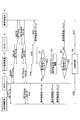
- FIG. 2 is an operation sequence diagram schematically showing an operation procedure of the IP telephone network 100.
- FIG. 2 only the incoming side interpolation packet generated when the incoming side transmission packet transmitted from the incoming side terminal 6 is interrupted for some reason for the convenience of drawing is shown.
- the calling side interpolation packet generated when the calling side transmission packet transmitted from the calling side terminal 1 is interrupted will be described later.
- the telephone numbers and IP addresses of the calling side terminal 1 and the called side terminal 6 are registered in the SIP servers 3 and 4 in advance. Alternatively, the telephone number and the IP address may be transmitted to the SIP servers 3 and 4 when each handset is picked up for the first time.
- the telephone number of the called side terminal 6 is dialed from the calling side terminal 1.
- an INVITE message is transmitted from the calling terminal 1 to the SIP server 3, and the SIP server 3 returns a provisional response of 100 Trying to the calling terminal 1.
- the provisional response of the INVITE message and 100 Trying is sequentially repeated between the SIP server 3 and the RTP monitoring device 10, the RTP monitoring device 10 and the SIP server 4, and the SIP server 4 and the called terminal 6.
- the called terminal 6 Upon receiving the INVITE message, the called terminal 6 transmits a 180Ringing provisional response to the calling terminal 1 (180Ringing). While receiving 180 Ringing, the calling terminal 1 can hear a ringing tone.
- the called terminal 6 When the handset of the called terminal 6 is lifted, the called terminal 6 transmits a 200OK success response to the calling terminal 1 (200OK).
- the calling terminal 1 transmits the ACK message directly to the called terminal 6 because it can know the IP address of the called terminal 6 when receiving 200OK.
- the transmission of the ACK message means that a line has been established (session established) between the calling terminal 1 and the called terminal 6. After the line is established, a voice packet, which is main information, is transmitted between the calling terminal 1 and the called terminal 6 using RTP. While the circuit is established, the SIP server 3, the RTP monitoring device 10, and the SIP server 4 monitor the distribution of RTP packets in the respective packet transfer networks 2 and 5.
- the called side transmission packet (voice packet) transmitted from the called side terminal 6 to the calling side terminal 1 is transmitted to the calling side terminal 1 (NO in step S1).
- a first monitoring timer (not shown) that counts the first timer value T1 provided in the RTP monitoring device 10 is reset every time the incoming call side transmission packet flows through the packet transfer network 2.
- the first timer value T1 is a timer value that measures the time during which the RTP disconnection detection function in the packet transfer network 2 operates.
- the SIP server 3 detects the disconnection of the line based on the first timer value T1, and transmits a BYE message indicating the disconnection of the line to the calling terminal 1 and the called terminal 6; Communication between both terminals ends.
- a called-side interpolation packet for interpolating the stopped called-side transmission packet is generated for a predetermined time after the first monitoring timer expires.
- the generated called side interpolation packet is transmitted to the SIP server 3 and the calling side terminal 1 (step S2).
- the time for which the called side interpolation packet is transmitted is from when the first monitoring timer expires (YES in step S1) until the second monitoring timer (second timer value T2) expires (YES in step S3). Is the time.
- the called side interpolation packet is transmitted to the SIP server 3 and the calling side terminal 1 for 10 to 30 seconds. Accordingly, the corresponding line of the packet transfer network 2 is not disconnected during that time. That is, since the callee side interpolation packet circulates in the packet transfer network 2 with a short timer value, disconnection of the line by the RTP disconnection detection function on the packet transfer network 2 side is suppressed.
- the RTP monitoring apparatus 10 presets timer values of the calling side network and the called side network, and performs interpolation packets (for example, called side interpolation packets) only for the difference between the timer values. Generate. As a result, the line can be disconnected based on the larger timer value.
- first timer value T1 is smaller than the second timer value T2
- first timer value T1 may be larger than the second timer value T2.
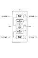
- FIG. 3 is a block diagram illustrating a functional configuration example of the RTP monitoring apparatus 10.
- notations such as a communication interface unit, a control unit, and a SIP message analysis unit, which are general configurations, are omitted.
- the RTP monitoring apparatus 10 includes a first monitoring timer 11, a second monitoring timer 12, a line disconnection unit 13, a first relay interpolation unit 14, and a second relay interpolation unit 15.
- Each functional component of the RTP monitoring apparatus 10 is realized by a computer including a ROM, a RAM, a CPU, and the like, for example.
- the processing content of the function that each functional component should have is described by a program.
- the line disconnecting unit 13 is not an indispensable functional component. The reason will be described later.
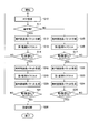
- FIG. 4 is a flowchart showing a processing procedure of the RTP monitoring apparatus 10.
- FIG. 4 shows a processing procedure after a line is established between the calling terminal 1 and the called terminal 6.
- FIG. 4 shows a call-side transmission packet and a call-side transmission packet received by the control unit of the RTP monitoring apparatus 10 (not shown) from the call-side terminal 6 and the call-side terminal 1, respectively. It is a flowchart shown in the example allocated to the 1st relay interpolation part 14 and the 2nd relay interpolation part 15, respectively.
- the first relay interpolation unit 14 relays the received called side transmission packet to the calling side terminal 1 (step S12).
- the first monitoring timer 11 is reset by the received incoming call transmission packet (step S13). The reset of the first monitoring timer 11 is repeatedly performed every time the incoming call side transmission packet is received.
- the first monitoring timer 11 does not time out unless the incoming side transmission packet transmitted from the incoming side terminal 6 is interrupted for the first timer value T1 or more. It is assumed that for some reason, the incoming side transmission packet transmitted from the incoming side terminal 6 is interrupted, and the outgoing side transmission packet transmitted from the outgoing side terminal 1 is continuously received.
- the second relay interpolation unit 15 relays the received calling side transmission packet to the called side terminal 6 (step S18). And the 2nd monitoring timer 12 is reset with the received calling side transmission packet (step S19).
- the control unit causes the first relay interpolating unit 14 to generate a called side interpolation packet for interpolating the interrupted called side transmission packet, and the generated called side interpolation packet to the calling side. A command to be transmitted to the terminal 1 is issued.
- the interrupted called side transmission packet is interpolated by the called side interpolation packet generated by the first relay interpolation unit 14 (step S20).
- the generation and interpolation of the called side interpolation packet are repeated until the second timer value T2 timed by the second monitoring timer 12 is finished (NO loop in step S21).
- the first timer value T1 and the second timer value T2 are stored in advance in, for example, a ROM or the like that constitutes the RTP monitoring apparatus 10.
- the line disconnecting unit 13 When the second monitoring timer 12 finishes counting the second timer value T2 after reception of the calling side transmission packet from the calling side terminal 1 is interrupted (YES in step S21), the line disconnecting unit 13 has already Since the time count of the first timer value T1 is also up, a BYE message indicating line disconnection is transmitted to each of the calling terminal 1 and the called terminal 6 to notify the disconnection of the line (step S26). ). Note that the SIP server 3 may be notified of line disconnection. That is, since the RTP disconnection detection function may be provided in the SIP servers 3 and 4, the BYE message may be transmitted using the functions of the SIP servers 3 and 4. In this case, the line disconnecting unit 13 of the RTP monitoring apparatus 10 is not necessary.
- the second relay interpolation unit 15 relays the received calling side transmission packet to the called side terminal 6 (Step S15).
- the second monitoring timer 12 is reset by the received calling side transmission packet (step S16). The reset of the second monitoring timer 11 is repeatedly performed every time the calling side transmission packet is received.
- the second monitoring timer 12 does not time up unless the calling side transmission packet transmitted from the calling side terminal 1 is interrupted for the second timer value T2 or more. For some reason, it is assumed that the calling side transmission packet transmitted from the calling side terminal 1 is interrupted, and the called side transmission packet transmitted from the called side terminal 6 is continuously received.
- the first relay interpolation unit 14 relays the received call-side transmission packet to the call-side terminal 1 (step S22). And the 1st monitoring timer 11 is reset with the received callee side transmission packet (step S23).
- the control unit causes the second relay interpolation unit 15 to generate a calling side interpolation packet for interpolating the disconnected calling side transmission packet, and the generated calling side interpolation packet to the called side. A command to be transmitted to the terminal 6 is issued.
- the interrupted calling side transmission packet is interpolated by the calling side interpolation packet generated by the second relay interpolation unit 15 (step S24).
- the generation and interpolation of the calling side interpolation packet are repeated until the time measurement of the first timer value T2 timed by the first monitoring timer 11 is completed (NO loop of step S25).
- the line disconnecting unit 13 When the first monitoring timer 11 finishes counting the first timer value T1 after reception of the calling side transmission packet from the calling side terminal 1 is interrupted (YES in step S25), the line disconnecting unit 13 has already Since the time count of the second timer value T2 is also up, a BYE message indicating line disconnection is transmitted to each of the calling terminal 1 and the called terminal 6 to notify the disconnection of the line (step S26). ).
- the RTP monitoring apparatus 10 performs the first monitoring that measures the first timer value T1 that represents a predetermined time after the incoming side transmission packet transmitted from the incoming side terminal 6 stops.
- a timer 11, a second monitoring timer 12 that counts a second timer value T2 indicating a predetermined time after the calling side transmission packet transmitted from the calling side terminal 1 is interrupted, and a called side transmission packet is called.
- the caller side When the first monitoring timer 11 is timed up and the second monitoring timer 12 is timing, the caller side generates a callee side interpolation packet for interpolating the callee side transmission packet.
- the second monitoring timer 12 is timed up, and the first monitoring timer 11 is measuring time , Caller send packet
- the second relay interpolation unit 15 that generates and transmits the calling side interpolation packet to be transmitted to the called side terminal 6 and the first monitoring timer 11 and the second monitoring timer 12 have timed out, the calling side terminal 1 And a line disconnecting unit 13 for notifying both of the called terminal 6 of the disconnection of the line.
- an interpolation packet (calling side interpolation packet, called side interpolation packet) is transmitted and interpolated toward a network with a short timer value (packet transfer network), so that the RTP disconnection detection function of the network with a small timer value can be realized.
- the operation is suppressed, and the RTP break detection function of the network having a large timer value operates.
- the RTP disconnection detection function can be appropriately operated even when networks having different timer values are connected. That is, it is possible to continue using the RTP disconnection detection function among all the operators while maintaining the policy of each network without affecting the existing facilities and devices.
- the timing processing of the first monitoring timer 11 and the second monitoring timer 12 is performed independently. Accordingly, the magnitudes of the first timer value T1 and the second timer value T2 may be such that the first timer value T1 is smaller than the second timer value T2, and the first timer value T1 is smaller than the second timer value T2. It can be large.
- the called side interpolation packet and the calling side interpolation packet generated by the first relay interpolation unit 14 and the second relay interpolation unit 15 are, for example, silent packets if they are voice packets. If a silent packet is transmitted over several tens of seconds, the user may feel anxious about an unexplained failure.
- each of the called side interpolation packet and the calling side interpolation packet may have a meaning.
- a call-side interpolation packet and a call-side interpolation packet may be used for transmission of voice guidance such as “communication is unstable”.
- Information such as “communication is unstable” may be transmitted as text information.
- the first relay interpolation unit 14 transmits information indicating that the packet is a packet for interpolating the incoming side transmission packet to the incoming side interpolation packet and transmits it to the calling side terminal 1, and the second relay interpolation unit 15. Transmits information indicating that the packet is a packet for interpolating the calling side transmission packet to the calling side interpolation packet and transmits it to the called side terminal 6. Thereby, since the user can grasp the situation, the user does not feel uneasy.
- first timer value T1 and the second timer value T2 have been described as being stored in advance in, for example, a ROM or the like constituting the RTP monitoring apparatus 10, but the present invention is not limited to this example.
- the first timer value T1 and the second timer value T2 may be described in the SIP message.
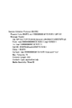
- FIG. 5 shows a specific example of the SIP INVITE message.
- the timer value of 30 seconds is described in the bottom line of FIG.
- the first timer value T1 and the second timer value T2 may be described in the INVITE message, and the description may be analyzed by the SIP message analysis unit (not shown) and held in the RAM or the like. .
- the second relay interpolation unit 15 refers to the state of the line disconnection unit 13 (a control line connecting the line disconnection unit 13 and the second relay interpolation unit 15 (FIG. 3)), and performs call-side interpolation according to the state.
- a packet may be generated.
- the second relay interpolation unit 15 generates a call-side interpolation packet while the first monitoring timer 11 times out and the second monitoring timer 12 measures time. The same applies to the calling side interpolation packet.
- the present invention is not limited to the above embodiment, and can be modified within the scope of the gist thereof.
Landscapes
- Engineering & Computer Science (AREA)
- Computer Networks & Wireless Communication (AREA)
- Signal Processing (AREA)
- Multimedia (AREA)
- Health & Medical Sciences (AREA)
- Cardiology (AREA)
- General Health & Medical Sciences (AREA)
- Business, Economics & Management (AREA)
- General Business, Economics & Management (AREA)
- Environmental & Geological Engineering (AREA)
- Computer Security & Cryptography (AREA)
- Data Exchanges In Wide-Area Networks (AREA)
- Telephonic Communication Services (AREA)
Abstract
The purpose of the present invention is to enable an RTP interrupt detection function to operate properly even when networks having different timer values are connected with each other. The RTP monitoring device is provided with: a first monitoring timer 11 for counting a first timer value indicating a predetermined amount of time after a called-side transmission packet transmitted from a called-side terminal 6 is interrupted; a second monitoring timer 12 for counting a second timer value indicating a predetermined amount of time after a caller-side transmission packet transmitted from a caller-side terminal 1 is interrupted; a first relay/interpolation unit 14 for relaying the called-side transmission packet to the caller-side terminal 1, and for generating and transmitting a called-side interpolation packet for interpolating the called-side transmission packet to the caller-side terminal 1 when the counting time of the first monitoring timer 11 has expired and the second monitoring timer 12 is still counting; and a second relay/interpolation unit 15 for relaying the caller-side transmission packet to the called-side terminal 6, and for generating and transmitting a caller-side interpolation packet for interpolating the caller-side transmission packet to the called-side terminal 6 when the counting time of the second monitoring timer 12 has expired and the first monitoring timer 11 is still counting.
Description
本発明は、RTP(Real-time Transport Protocol)を用いてデータを転送するパケット転送網を接続するRTP監視装置及びRTP監視方法に関する。
The present invention relates to an RTP monitoring apparatus and an RTP monitoring method for connecting a packet transfer network for transferring data using RTP (Real-time Transport Protocol).
パケット転送網を運営する運営事業者は、通信品質の確保及び誤課金防止の観点から回線ごとの音声や映像のパケット(RTPパケット)の流通状況を監視し、一定時間の間、RTPパケットが流通していないことを検出した際に該当する回線を切断する場合がある。この回線を切断する機能を、以降、RTP断検出機能と称する。回線の切断は、非特許文献1~4に記載された標準に基づいて行われる。
The operator operating the packet transfer network monitors the distribution status of voice and video packets (RTP packets) for each line from the viewpoint of ensuring communication quality and preventing erroneous charges, and distributes RTP packets for a certain period of time. When it is detected that there is no connection, the corresponding line may be disconnected. This function of disconnecting the line is hereinafter referred to as an RTP disconnection detection function. The line disconnection is performed based on the standards described in Non-Patent Documents 1 to 4.
RTP断検出機能は、RTPパケットの流通しない時間をタイマで監視し、RTPパケットが流通しない時間がタイマ時間を越えると回線を切断するように作用する。回線を切断するまでの時間を決定するタイマ時間を設定するタイマ値は、ネットワーク(網)の信頼性等に基づき網のポリシーによって設定されるため、網ごとに異なる場合がある。
The RTP disconnection detection function monitors the time when RTP packets do not circulate with a timer, and acts to disconnect the line when the time when RTP packets do not circulate exceeds the timer time. The timer value for setting the timer time for determining the time until the line is disconnected is set according to the network policy based on the reliability of the network (network), and may be different for each network.
タイマ値が異なる網同士が相互接続された場合、短いタイマ値に従って回線が切断されてしまう。その結果、タイマ値が長い網においては、回線を切断する機能が適切に動作しないという課題がある。
When networks with different timer values are interconnected, the line is disconnected according to the short timer value. As a result, in a network with a long timer value, there is a problem that the function of disconnecting the line does not operate properly.
本発明は、この課題を鑑みてなされたものであり、タイマ値が異なる網同士が相互接続された場合でもRTP断検出機能が適切に動作するようにしたRTP監視装置及びRTP監視方法を提供することを目的とする。
The present invention has been made in view of this problem, and provides an RTP monitoring apparatus and an RTP monitoring method in which an RTP disconnection detection function operates appropriately even when networks having different timer values are interconnected. For the purpose.
本発明の一態様に係るRTP監視装置は、パケット転送網を接続するRTP監視装置であって、着呼側端末から送信される着呼側送信パケットが途絶えてからの所定時間を表す第1タイマ値を計時する第1監視タイマと、発呼側端末から送信される発呼側送信パケットが途絶えてからの所定時間を表す第2タイマ値を計時する第2監視タイマと、前記着呼側送信パケットを前記発呼側端末に中継すると共に、前記第1監視タイマがタイムアップし、前記第2監視タイマが計時中の場合に、前記着呼側送信パケットを補間する着呼側補間パケットを生成して前記発呼側端末に送信する第1中継補間部と、前記発呼側送信パケットを前記着呼側端末に中継すると共に、前記第2監視タイマがタイムアップし、前記第1監視タイマが計時中の場合に、前記発呼側送信パケットを補間する発呼側補間パケットを生成して前記着呼側端末に送信する第2中継補間部とを備えることを要旨とする。
An RTP monitoring apparatus according to an aspect of the present invention is an RTP monitoring apparatus that connects a packet transfer network, and includes a first timer that represents a predetermined time after a call-side transmission packet transmitted from a call-receiving terminal is interrupted. A first monitoring timer that counts a value; a second monitoring timer that counts a second timer value indicating a predetermined time after the calling side transmission packet transmitted from the calling side terminal stops; and the called side transmission Relays the packet to the calling terminal, and generates a called side interpolation packet for interpolating the called side transmission packet when the first monitoring timer times out and the second monitoring timer is timing A first relay interpolating unit for transmitting to the calling side terminal, relaying the calling side transmission packet to the called side terminal, the second monitoring timer being timed up, and the first monitoring timer being When timing is in progress , And summarized in that and a second relay interpolation unit generating and transmitting a calling interpolation packets for interpolating the calling packet transmitted the called terminal.
また、本発明の一態様に係るRTP監視方法は、上記のRTP監視装置が実行するRTP監視方法であって、着呼側端末から送信される着呼側送信パケットが途絶えてからの所定時間を表す第1タイマ値を計時し、発呼側端末から送信される発呼側送信パケットが途絶えてからの所定時間を表す第2タイマ値を計時し、前記着呼側送信パケットを前記発呼側端末に中継すると共に、前記第1タイマ値の計時が終了し、前記第2タイマ値が計時中の場合に、前記着呼側送信パケットを補間する着呼側補間パケットを生成して前記発呼側端末に送信し、前記発呼側送信パケットを前記着呼側端末に中継すると共に、前記第2タイマ値の計時を終了し、前記第1タイマ値が計時中の場合に、前記発呼側送信パケットを補間する発呼側補間パケットを生成して前記着呼側端末に送信することを要旨とする。
An RTP monitoring method according to an aspect of the present invention is an RTP monitoring method executed by the above RTP monitoring apparatus, wherein a predetermined time after the incoming side transmission packet transmitted from the incoming side terminal is interrupted. A first timer value that represents the time, a second timer value that represents a predetermined time after the caller-side transmission packet transmitted from the calling-side terminal is interrupted, and the call-side transmission packet that is the caller-side transmission packet. Relaying to the terminal and generating a called side interpolation packet for interpolating the called side transmission packet when the timing of the first timer value is ended and the second timer value is being timed. Transmitting to the caller terminal, relaying the caller-side transmission packet to the callee terminal, ending timing of the second timer value, and if the first timer value is being clocked, the caller side Calling side interpolation packet to interpolate the transmission packet Generated and to increase the transmission to the called terminal.
本発明によれば、タイマ値が異なる網同士が接続された場合でもRTP断検出機能を適切に動作させることができる。
According to the present invention, even when networks with different timer values are connected, the RTP disconnection detection function can be appropriately operated.
以下、本発明の実施形態について図面を用いて説明する。複数の図面中同一のものには同じ参照符号を付し、説明は繰り返さない。
Hereinafter, embodiments of the present invention will be described with reference to the drawings. The same reference numerals are given to the same components in a plurality of drawings, and the description will not be repeated.
(IP電話網)
図1は、本発明の実施形態に係るRTP監視装置を用いたIP電話網の構成例を示すブロック図である。図1に示すIP電話網100は、VoIP(Voice over Internet Protocol)技術を利用した電話サービスを提供するネットワークである。IP電話網100は、パス制御プロトコルとしてSIP(Session Initiation Protocol)を利用したネットワークであり、ネットワークに接続する端末間で疎通する主情報(データ)は、RTP(Realtime Transport Protocol)を用いて伝送される。 (IP telephone network)
FIG. 1 is a block diagram showing a configuration example of an IP telephone network using an RTP monitoring apparatus according to an embodiment of the present invention. AnIP telephone network 100 shown in FIG. 1 is a network that provides a telephone service using VoIP (Voice over Internet Protocol) technology. The IP telephone network 100 is a network that uses SIP (Session Initiation Protocol) as a path control protocol, and main information (data) communicated between terminals connected to the network is transmitted using RTP (Realtime Transport Protocol). The
図1は、本発明の実施形態に係るRTP監視装置を用いたIP電話網の構成例を示すブロック図である。図1に示すIP電話網100は、VoIP(Voice over Internet Protocol)技術を利用した電話サービスを提供するネットワークである。IP電話網100は、パス制御プロトコルとしてSIP(Session Initiation Protocol)を利用したネットワークであり、ネットワークに接続する端末間で疎通する主情報(データ)は、RTP(Realtime Transport Protocol)を用いて伝送される。 (IP telephone network)
FIG. 1 is a block diagram showing a configuration example of an IP telephone network using an RTP monitoring apparatus according to an embodiment of the present invention. An
図1に示すIP電話網100は、発呼側端末1、パケット転送網2、RTP監視装置10、SIPサーバ3、SIPサーバ4、RTP監視装置20、パケット転送網5、及び着呼側端末6を備える。パケット転送網2は例えばA社、パケット転送網5は例えばB社といった様に運営事業者が異なる例を示す。
An IP telephone network 100 shown in FIG. 1 includes a calling side terminal 1, a packet transfer network 2, an RTP monitoring device 10, an SIP server 3, an SIP server 4, an RTP monitoring device 20, a packet transfer network 5, and a called side terminal 6. Is provided. For example, the packet transfer network 2 is a company A, and the packet transfer network 5 is a company B, for example.
ネットワークを運営する運営事業者間で、ポリシーが異なる場合がある。例えば、RTPパケットが流通していないことを検出した場合に、該当する回線を切断するRTP断検出機能を作動させる時間(タイマ値)は異なる場合がある。
The policy may differ between operators operating the network. For example, when it is detected that an RTP packet is not distributed, the time (timer value) for operating the RTP disconnection detection function for disconnecting the corresponding line may be different.
SIPサーバ3,4は、SIPを利用したIP電話サービスの管理制御を行うサーバであり、パケット転送網2,5のそれぞれに設けられる。
SIP servers 3 and 4 are servers that perform management control of IP telephone services using SIP, and are provided in each of the packet transfer networks 2 and 5.
RTP監視装置10,20は、隣接するネットワーク間で主情報のRTPパケットを疎通できるようにする装置であり、RTP断検出機能も備える。RTP監視装置10,20は、一般的にSBC(Session Border Controller)と称される。
The RTP monitoring devices 10 and 20 are devices that enable communication of RTP packets of main information between adjacent networks, and also have an RTP disconnection detection function. The RTP monitoring devices 10 and 20 are generally referred to as SBC (Session Border Controller).
RTP監視装置10,20は、参照番号を異にしているが同じものである。RTP監視装置10,20は、それぞれ別々のSBCと一体化して構成しても良いし、SIPサーバ3,4に含めても良い。
The RTP monitoring devices 10 and 20 are the same, although the reference numbers are different. The RTP monitoring devices 10 and 20 may be integrated with separate SBCs or may be included in the SIP servers 3 and 4.
以降の説明では、運営事業者がA社であるパケット転送網2のRTP断検出機能が動作する第1タイマ値をT1、運営事業者がB社であるパケット転送網5のRTP断検出機能が動作する第2タイマ値をT2であると仮定する。例えば、T1は10秒、T2は30秒といったタイマ値である。RTP断検出は、RTP監視装置10又はRTP監視装置20のどちらかで行う。どちらで行うかは、運営事業者間の取り決めによる。以降において、RTP監視装置10がRTP断検出を行う例で説明する。
In the following description, the first timer value at which the RTP disconnection detection function of the packet transfer network 2 whose operating carrier is the company A operates is T1, and the RTP disconnection detection function of the packet transfer network 5 whose operating operator is the company B is Assume that the second timer value to operate is T2. For example, T1 is a timer value such as 10 seconds and T2 is 30 seconds. RTP disconnection detection is performed by either the RTP monitoring device 10 or the RTP monitoring device 20. Which is done depends on the agreement between the operators. Hereinafter, an example in which the RTP monitoring apparatus 10 performs RTP disconnection detection will be described.
図2は、IP電話網100の動作手順を模式的に示す動作シーケンス図である。図2では、作図の都合により着呼側端末6から送信される着呼側送信パケットが何らかの理由により途絶した場合に生成される着呼側補間パケットのみを表記する。発呼側端末1から送信される発呼側送信パケットが途絶した場合に生成される発呼側補間パケットについては後述する。
FIG. 2 is an operation sequence diagram schematically showing an operation procedure of the IP telephone network 100. In FIG. 2, only the incoming side interpolation packet generated when the incoming side transmission packet transmitted from the incoming side terminal 6 is interrupted for some reason for the convenience of drawing is shown. The calling side interpolation packet generated when the calling side transmission packet transmitted from the calling side terminal 1 is interrupted will be described later.
発呼側端末1と着呼側端末6のそれぞれの電話番号及びIPアドレスは、SIPサーバ3,4に予め登録されている。または、それぞれの受話器を最初に取り上げたときに、電話番号及びIPアドレスをSIPサーバ3,4に送信するようにしてもよい。
The telephone numbers and IP addresses of the calling side terminal 1 and the called side terminal 6 are registered in the SIP servers 3 and 4 in advance. Alternatively, the telephone number and the IP address may be transmitted to the SIP servers 3 and 4 when each handset is picked up for the first time.
発呼側端末1と着呼側端末6の間で通信を開始する場合、例えば発呼側端末1から着呼側端末6の電話番号をダイヤルする。この時、発呼側端末1からSIPサーバ3へINVITEメッセージが送信され、SIPサーバ3は100Tryingの暫定応答を発端側端末1に返信する。
When communication is started between the calling side terminal 1 and the called side terminal 6, for example, the telephone number of the called side terminal 6 is dialed from the calling side terminal 1. At this time, an INVITE message is transmitted from the calling terminal 1 to the SIP server 3, and the SIP server 3 returns a provisional response of 100 Trying to the calling terminal 1.
このINVITEメッセージと100Tryingの暫定応答は、順次、SIPサーバ3とRTP監視装置10、RTP監視装置10とSIPサーバ4、及びSIPサーバ4と着呼側端末6の間で繰り返される。
The provisional response of the INVITE message and 100 Trying is sequentially repeated between the SIP server 3 and the RTP monitoring device 10, the RTP monitoring device 10 and the SIP server 4, and the SIP server 4 and the called terminal 6.
着呼側端末6は、INVITEメッセージを受信すると180Ringingの暫定応答を、発呼側端末1に向けて送信する(180Ringing)。180Ringingを受信している間、発呼側端末1では呼出音が聞こえる。
Upon receiving the INVITE message, the called terminal 6 transmits a 180Ringing provisional response to the calling terminal 1 (180Ringing). While receiving 180 Ringing, the calling terminal 1 can hear a ringing tone.
着呼側端末6の受話器が上げられると、着呼側端末6は200OKの成功応答を、発呼側端末1に向けて送信する(200OK)。
When the handset of the called terminal 6 is lifted, the called terminal 6 transmits a 200OK success response to the calling terminal 1 (200OK).
発呼側端末1は、200OKを受信すると着呼側端末6のIPアドレスが分かるため、直接ACKメッセージを着呼側端末6へ送信する。ACKメッセージの送信は、発呼側端末1と着呼側端末6の間で回線が確立(セッション確立)されたことを意味する。回線が確立された後は、発呼側端末1と着呼側端末6の間で、主情報である音声パケットがRTPを用いて伝送される。回線が確立されている間のSIPサーバ3、RTP監視装置10、及びSIPサーバ4は、それぞれのパケット転送網2,5内のRTPパケットの流通を監視する。
The calling terminal 1 transmits the ACK message directly to the called terminal 6 because it can know the IP address of the called terminal 6 when receiving 200OK. The transmission of the ACK message means that a line has been established (session established) between the calling terminal 1 and the called terminal 6. After the line is established, a voice packet, which is main information, is transmitted between the calling terminal 1 and the called terminal 6 using RTP. While the circuit is established, the SIP server 3, the RTP monitoring device 10, and the SIP server 4 monitor the distribution of RTP packets in the respective packet transfer networks 2 and 5.
着呼側端末6から発呼側端末1に送信される着呼側送信パケット(音声パケット)は、発呼側端末1に送信される(ステップS1のNO)。ここで、RTP監視装置10が備える第1タイマ値T1を計時する第1監視タイマ(図示せず)は、着呼側送信パケットがパケット転送網2内を流通する度にリセットされるものと仮定する。第1タイマ値T1は、パケット転送網2内のRTP断検出機能が動作する時間を計時するタイマ値である。
The called side transmission packet (voice packet) transmitted from the called side terminal 6 to the calling side terminal 1 is transmitted to the calling side terminal 1 (NO in step S1). Here, it is assumed that a first monitoring timer (not shown) that counts the first timer value T1 provided in the RTP monitoring device 10 is reset every time the incoming call side transmission packet flows through the packet transfer network 2. To do. The first timer value T1 is a timer value that measures the time during which the RTP disconnection detection function in the packet transfer network 2 operates.
ここで、何らかの理由によりパケット転送網2内の着呼側送信パケットの流通が途絶えた場合を想定する。この場合、従来技術では、SIPサーバ3は第1タイマ値T1に基づいて回線の切断を検出し、回線の切断を意味するBYEメッセージを発呼側端末1と着呼側端末6に送信し、両端末間の通信は終了する。
Here, a case is assumed where the distribution of the incoming side transmission packet in the packet transfer network 2 is interrupted for some reason. In this case, in the prior art, the SIP server 3 detects the disconnection of the line based on the first timer value T1, and transmits a BYE message indicating the disconnection of the line to the calling terminal 1 and the called terminal 6; Communication between both terminals ends.
本実施形態に係るRTP監視装置10においては、第1監視タイマがタイムアップした後の所定時間の間、途絶えた着呼側送信パケットを補間する着呼側補間パケットが生成される。そして、生成された着呼側補間パケットは、SIPサーバ3と発呼側端末1に送信される(ステップS2)。着呼側補間パケットが送信される時間は、第1監視タイマがタイムアップ(ステップS1のYES)してから第2監視タイマ(第2タイマ値T2)がタイムアップ(ステップS3のYES)するまでの時間である。
In the RTP monitoring apparatus 10 according to the present embodiment, a called-side interpolation packet for interpolating the stopped called-side transmission packet is generated for a predetermined time after the first monitoring timer expires. The generated called side interpolation packet is transmitted to the SIP server 3 and the calling side terminal 1 (step S2). The time for which the called side interpolation packet is transmitted is from when the first monitoring timer expires (YES in step S1) until the second monitoring timer (second timer value T2) expires (YES in step S3). Is the time.
この例では、T1=10秒、T2=30秒であるので、10~30秒の間は、着呼側補間パケットがSIPサーバ3と発呼側端末1に送信される。よってその間、パケット転送網2の該当する回線は切断されない。つまり、タイマ値の短いパケット転送網2内に着呼側補間パケットが流通するので、パケット転送網2側のRTP断検知機能による回線の切断は抑止されることになる。
In this example, since T1 = 10 seconds and T2 = 30 seconds, the called side interpolation packet is transmitted to the SIP server 3 and the calling side terminal 1 for 10 to 30 seconds. Accordingly, the corresponding line of the packet transfer network 2 is not disconnected during that time. That is, since the callee side interpolation packet circulates in the packet transfer network 2 with a short timer value, disconnection of the line by the RTP disconnection detection function on the packet transfer network 2 side is suppressed.
つまり、本実施形態に係るRTP監視装置10は、発呼側の網と着呼側の網のタイマ値を予め設定し、タイマ値の差分の時間のみ補間パケット(例えば着呼側補間パケット)を生成する。その結果、大きい方のタイマ値に基づいて回線を切断することが可能になる。
In other words, the RTP monitoring apparatus 10 according to the present embodiment presets timer values of the calling side network and the called side network, and performs interpolation packets (for example, called side interpolation packets) only for the difference between the timer values. Generate. As a result, the line can be disconnected based on the larger timer value.
なお、第1タイマ値T1が第2タイマ値T2よりも小さい例で説明を行ったが、この例に限定されない。第1タイマ値T1は、第2タイマ値T2よりも大きくてもよい。
In addition, although the description has been given with an example in which the first timer value T1 is smaller than the second timer value T2, it is not limited to this example. The first timer value T1 may be larger than the second timer value T2.
第1タイマ値T1が第2タイマ値T2よりも大きい場合、及び発呼側端末1から着呼側端末6に送信される発呼側送信パケットを監視する動作については、次のRTP監視装置の説明の中で述べる。
When the first timer value T1 is larger than the second timer value T2 and the operation of monitoring the calling side transmission packet transmitted from the calling side terminal 1 to the called side terminal 6, the following RTP monitoring device State in the description.
(RTP監視装置)
図3は、RTP監視装置10の機能構成例を示すブロック図である。図3において、一般的な構成である通信インターフェース部、制御部、及びSIPメッセージ解析部等の表記は省略している。 (RTP monitoring device)
FIG. 3 is a block diagram illustrating a functional configuration example of theRTP monitoring apparatus 10. In FIG. 3, notations such as a communication interface unit, a control unit, and a SIP message analysis unit, which are general configurations, are omitted.
図3は、RTP監視装置10の機能構成例を示すブロック図である。図3において、一般的な構成である通信インターフェース部、制御部、及びSIPメッセージ解析部等の表記は省略している。 (RTP monitoring device)
FIG. 3 is a block diagram illustrating a functional configuration example of the
図3に示すようにRTP監視装置10は、第1監視タイマ11、第2監視タイマ12、回線切断部13、第1中継補間部14、及び第2中継補間部15を備える。RTP監視装置10の各機能構成部は、例えば、ROM、RAM、CPU等からなるコンピュータで実現される。各機能構成部をコンピュータによって実現する場合、各機能構成部が有すべき機能の処理内容はプログラムによって記述される。なお、回線切断部13は、必須の機能構成部ではない。その理由については後述する。
3, the RTP monitoring apparatus 10 includes a first monitoring timer 11, a second monitoring timer 12, a line disconnection unit 13, a first relay interpolation unit 14, and a second relay interpolation unit 15. Each functional component of the RTP monitoring apparatus 10 is realized by a computer including a ROM, a RAM, a CPU, and the like, for example. When each functional component is realized by a computer, the processing content of the function that each functional component should have is described by a program. The line disconnecting unit 13 is not an indispensable functional component. The reason will be described later.
図4は、RTP監視装置10の処理手順を示すフローチャートである。図4は、発呼側端末1と着呼側端末6の間で回線が確立された後の処理手順を示す。
FIG. 4 is a flowchart showing a processing procedure of the RTP monitoring apparatus 10. FIG. 4 shows a processing procedure after a line is established between the calling terminal 1 and the called terminal 6.
なお、作図の都合により、図4は、図示しないRTP監視装置10の制御部が、着呼側端末6及び発呼側端末1からそれぞれ受信する着呼側送信パケットと発呼側送信パケットを、第1中継補間部14と第2中継補間部15にそれぞれ割り振る例で示すフローチャートである。
For convenience of drawing, FIG. 4 shows a call-side transmission packet and a call-side transmission packet received by the control unit of the RTP monitoring apparatus 10 (not shown) from the call-side terminal 6 and the call-side terminal 1, respectively. It is a flowchart shown in the example allocated to the 1st relay interpolation part 14 and the 2nd relay interpolation part 15, respectively.
先ず、着呼側端末6から発呼側端末1に向けて送信される音声パケットの監視動作について説明する。
First, the monitoring operation of the voice packet transmitted from the called terminal 6 toward the calling terminal 1 will be described.
受信した音声パケットが着呼側送信パケットである場合(ステップS11のYES)、第1中継補間部14は、受信した着呼側送信パケットを発呼側端末1に中継する(ステップS12)。この場合、受信した着呼側送信パケットによって第1監視タイマ11はリセットされる(ステップS13)。この第1監視タイマ11のリセットは、着呼側送信パケットが受信される度に繰り返して行われる。
When the received voice packet is a called side transmission packet (YES in step S11), the first relay interpolation unit 14 relays the received called side transmission packet to the calling side terminal 1 (step S12). In this case, the first monitoring timer 11 is reset by the received incoming call transmission packet (step S13). The reset of the first monitoring timer 11 is repeatedly performed every time the incoming call side transmission packet is received.
第1監視タイマ11は、着呼側端末6から送信されて来る着呼側送信パケットが第1タイマ値T1以上の間途絶しないとタイムアップしない。何らかの理由により、着呼側端末6から送信されて来る着呼側送信パケットが途絶え、発呼側端末1から送信されて来る発呼側送信パケットは続けて受信される場合を想定する。
The first monitoring timer 11 does not time out unless the incoming side transmission packet transmitted from the incoming side terminal 6 is interrupted for the first timer value T1 or more. It is assumed that for some reason, the incoming side transmission packet transmitted from the incoming side terminal 6 is interrupted, and the outgoing side transmission packet transmitted from the outgoing side terminal 1 is continuously received.
この場合、第2中継補間部15は、受信した発呼側送信パケットを着呼側端末6に中継する(ステップS18)。そして、受信した発呼側送信パケットで第2監視タイマ12をリセットする(ステップS19)。この時、図示しない制御部は、第1中継補間部14に対して途絶えた着呼側送信パケットを補間する着呼側補間パケットを生成させると共に、生成させた着呼側補間パケットを発呼側端末1に送信させる指令を発する。
In this case, the second relay interpolation unit 15 relays the received calling side transmission packet to the called side terminal 6 (step S18). And the 2nd monitoring timer 12 is reset with the received calling side transmission packet (step S19). At this time, the control unit (not shown) causes the first relay interpolating unit 14 to generate a called side interpolation packet for interpolating the interrupted called side transmission packet, and the generated called side interpolation packet to the calling side. A command to be transmitted to the terminal 1 is issued.
したがって、途絶えた着呼側送信パケットは、第1中継補間部14で生成された着呼側補間パケットによって補間される(ステップS20)。この着呼側補間パケットの生成と補間は、第2監視タイマ12が計時する第2タイマ値T2の計時を終了するまで繰り返される(ステップS21のNOのループ)。第1タイマ値T1と第2タイマ値T2は、RTP監視装置10を構成する例えばROM等に予め記憶されている。
Therefore, the interrupted called side transmission packet is interpolated by the called side interpolation packet generated by the first relay interpolation unit 14 (step S20). The generation and interpolation of the called side interpolation packet are repeated until the second timer value T2 timed by the second monitoring timer 12 is finished (NO loop in step S21). The first timer value T1 and the second timer value T2 are stored in advance in, for example, a ROM or the like that constitutes the RTP monitoring apparatus 10.
発呼側端末1からの発呼側送信パケットの受信が途絶えてから、第2監視タイマ12が第2タイマ値T2の計時を終了する(ステップS21のYES)と、回線切断部13は、既に第1タイマ値T1の計時もタイムアップしているので、発呼側端末1と着呼側端末6のそれぞれに回線の切断を意味するBYEメッセージを送信して回線の切断を通知する(ステップS26)。なお、回線の切断の通知は、SIPサーバ3に行わせてもよい。つまり、RTP断検出機能はSIPサーバ3,4に備えてもよいので、SIPサーバ3,4の当該機能を用いてBYEメッセージを送信するようにしてもよい。この場合、RTP監視装置10の回線切断部13は不要である。
When the second monitoring timer 12 finishes counting the second timer value T2 after reception of the calling side transmission packet from the calling side terminal 1 is interrupted (YES in step S21), the line disconnecting unit 13 has already Since the time count of the first timer value T1 is also up, a BYE message indicating line disconnection is transmitted to each of the calling terminal 1 and the called terminal 6 to notify the disconnection of the line (step S26). ). Note that the SIP server 3 may be notified of line disconnection. That is, since the RTP disconnection detection function may be provided in the SIP servers 3 and 4, the BYE message may be transmitted using the functions of the SIP servers 3 and 4. In this case, the line disconnecting unit 13 of the RTP monitoring apparatus 10 is not necessary.
以上、着呼側端末6が送信する着呼側送信パケットが途絶えた場合の動作を説明した。続けて、発呼側端末1から着呼側端末6に向けて送信される音声パケットの監視動作について説明する。
In the foregoing, the operation when the incoming side transmission packet transmitted by the incoming side terminal 6 is interrupted has been described. Subsequently, the monitoring operation of the voice packet transmitted from the calling terminal 1 to the called terminal 6 will be described.
受信した音声パケットが発呼側送信パケットである場合(ステップS11のNO)、第2中継補間部15は、受信した発呼側送信パケットを着呼側端末6に中継する(ステップS15)。この場合、受信した発呼側送信パケットによって第2監視タイマ12はリセットされる(ステップS16)。この第2監視タイマ11のリセットは、発呼側送信パケットが受信される度に繰り返して行われる。
When the received voice packet is a calling side transmission packet (NO in Step S11), the second relay interpolation unit 15 relays the received calling side transmission packet to the called side terminal 6 (Step S15). In this case, the second monitoring timer 12 is reset by the received calling side transmission packet (step S16). The reset of the second monitoring timer 11 is repeatedly performed every time the calling side transmission packet is received.
第2監視タイマ12は、発呼側端末1から送信されて来る発呼側送信パケットが第2タイマ値T2以上の間途絶しないとタイムアップしない。何らかの理由により、発呼側端末1から送信されて来る発呼側送信パケットが途絶え、着呼側端末6から送信されて来る着呼側送信パケットは続けて受信する場合を想定する。
The second monitoring timer 12 does not time up unless the calling side transmission packet transmitted from the calling side terminal 1 is interrupted for the second timer value T2 or more. For some reason, it is assumed that the calling side transmission packet transmitted from the calling side terminal 1 is interrupted, and the called side transmission packet transmitted from the called side terminal 6 is continuously received.
この場合、第1中継補間部14は、受信した着呼側送信パケットを発呼側端末1に中継する(ステップS22)。そして、受信した着呼側送信パケットで第1監視タイマ11をリセットする(ステップS23)。この時、図示しない制御部は、第2中継補間部15に対して途絶えた発呼側送信パケットを補間する発呼側補間パケットを生成させると共に、生成させた発呼側補間パケットを着呼側端末6に送信させる指令を発する。
In this case, the first relay interpolation unit 14 relays the received call-side transmission packet to the call-side terminal 1 (step S22). And the 1st monitoring timer 11 is reset with the received callee side transmission packet (step S23). At this time, the control unit (not shown) causes the second relay interpolation unit 15 to generate a calling side interpolation packet for interpolating the disconnected calling side transmission packet, and the generated calling side interpolation packet to the called side. A command to be transmitted to the terminal 6 is issued.
したがって、途絶えた発呼側送信パケットは、第2中継補間部15で生成された発呼側補間パケットによって補間される(ステップS24)。この発呼側補間パケットの生成と補間は、第1監視タイマ11が計時する第1タイマ値T2の計時を終了するまで繰り返される(ステップS25のNOのループ)。
Therefore, the interrupted calling side transmission packet is interpolated by the calling side interpolation packet generated by the second relay interpolation unit 15 (step S24). The generation and interpolation of the calling side interpolation packet are repeated until the time measurement of the first timer value T2 timed by the first monitoring timer 11 is completed (NO loop of step S25).
発呼側端末1からの発呼側送信パケットの受信が途絶えてから、第1監視タイマ11が第1タイマ値T1の計時を終了する(ステップS25のYES)と、回線切断部13は、既に第2タイマ値T2の計時もタイムアップしているので、発呼側端末1と着呼側端末6のそれぞれに回線の切断を意味するBYEメッセージを送信して回線の切断を通知する(ステップS26)。
When the first monitoring timer 11 finishes counting the first timer value T1 after reception of the calling side transmission packet from the calling side terminal 1 is interrupted (YES in step S25), the line disconnecting unit 13 has already Since the time count of the second timer value T2 is also up, a BYE message indicating line disconnection is transmitted to each of the calling terminal 1 and the called terminal 6 to notify the disconnection of the line (step S26). ).
以上説明したように本実施形態に係るRTP監視装置10は、着呼側端末6から送信される着呼側送信パケットが途絶えてからの所定時間を表す第1タイマ値T1を計時する第1監視タイマ11と、発呼側端末1から送信される発呼側送信パケットが途絶えてからの所定時間を表す第2タイマ値T2を計時する第2監視タイマ12と、着呼側送信パケットを発呼側端末1に中継すると共に、第1監視タイマ11がタイムアップし、第2監視タイマ12が計時中の場合に、着呼側送信パケットを補間する着呼側補間パケットを生成して発呼側端末1に送信する第1中継補間部14と、発呼側送信パケットを着呼側端末6に中継すると共に、第2監視タイマ12がタイムアップし、第1監視タイマ11が計時中の場合に、発呼側送信パケットを補間する発呼側補間パケットを生成して着呼側端末6に送信する第2中継補間部15と、第1監視タイマ11と第2監視タイマ12がタイムアップした場合に、発呼側端末1と着呼側端末6の双方へ回線の切断を通知する回線切断部13とを備える。
As described above, the RTP monitoring apparatus 10 according to this embodiment performs the first monitoring that measures the first timer value T1 that represents a predetermined time after the incoming side transmission packet transmitted from the incoming side terminal 6 stops. A timer 11, a second monitoring timer 12 that counts a second timer value T2 indicating a predetermined time after the calling side transmission packet transmitted from the calling side terminal 1 is interrupted, and a called side transmission packet is called. When the first monitoring timer 11 is timed up and the second monitoring timer 12 is timing, the caller side generates a callee side interpolation packet for interpolating the callee side transmission packet. When the first relay interpolating unit 14 to be transmitted to the terminal 1 and the calling side transmission packet are relayed to the called side terminal 6, the second monitoring timer 12 is timed up, and the first monitoring timer 11 is measuring time , Caller send packet When the second relay interpolation unit 15 that generates and transmits the calling side interpolation packet to be transmitted to the called side terminal 6 and the first monitoring timer 11 and the second monitoring timer 12 have timed out, the calling side terminal 1 And a line disconnecting unit 13 for notifying both of the called terminal 6 of the disconnection of the line.
これにより、タイマ値の短い網(パケット転送網)に向けて補間パケット(発呼側補間パケット、着呼側補間パケット)を送信して補間するので、タイマ値の小さい網のRTP断検出機能の作動は抑止され、タイマ値の大きい網のRTP断検出機能が作用することになる。
As a result, an interpolation packet (calling side interpolation packet, called side interpolation packet) is transmitted and interpolated toward a network with a short timer value (packet transfer network), so that the RTP disconnection detection function of the network with a small timer value can be realized. The operation is suppressed, and the RTP break detection function of the network having a large timer value operates.
以上述べたように本実施形態のRTP監視装置10とその監視方法によれば、タイマ値が異なる網同士が接続された場合でもRTP断検出機能を適切に動作させることができる。つまり、既存の設備及びデバイスに影響を与えることなく、各網のポリシーを維持しながら全ての運営事業者の間においてRTP断検出機能を利用し続けることができる。
As described above, according to the RTP monitoring apparatus 10 and its monitoring method of the present embodiment, the RTP disconnection detection function can be appropriately operated even when networks having different timer values are connected. That is, it is possible to continue using the RTP disconnection detection function among all the operators while maintaining the policy of each network without affecting the existing facilities and devices.
なお、図4を参照して説明したように、第1監視タイマ11と第2監視タイマ12の計時処理は、それぞれ独立して行われる。したがって、第1タイマ値T1と第2タイマ値T2の大きさは、第1タイマ値T1が第2タイマ値T2よりも小さくてもよいし、第1タイマ値T1が第2タイマ値T2よりも大きくてもよい。
Note that, as described with reference to FIG. 4, the timing processing of the first monitoring timer 11 and the second monitoring timer 12 is performed independently. Accordingly, the magnitudes of the first timer value T1 and the second timer value T2 may be such that the first timer value T1 is smaller than the second timer value T2, and the first timer value T1 is smaller than the second timer value T2. It can be large.
また、第1中継補間部14と第2中継補間部15が生成する着呼側補間パケットと発呼側補間パケットは、例えば、音声パケットであれば無音パケットである。無音パケットが数10秒の間にわたって送信されると、利用者は原因不明の故障が起きたと不安に思う場合がある。
In addition, the called side interpolation packet and the calling side interpolation packet generated by the first relay interpolation unit 14 and the second relay interpolation unit 15 are, for example, silent packets if they are voice packets. If a silent packet is transmitted over several tens of seconds, the user may feel anxious about an unexplained failure.
そこで、着呼側補間パケットと発呼側補間パケットに、それぞれ意味を持たせるようにしてもよい。例えば「通信が不安定になっております。」等の音声ガイダンスの送信に、着呼側補間パケットと発呼側補間パケットを用いてもよい。なお、「通信が不安定になっております。」等の情報は、テキスト情報として送信するようにしてもよい。
Therefore, each of the called side interpolation packet and the calling side interpolation packet may have a meaning. For example, a call-side interpolation packet and a call-side interpolation packet may be used for transmission of voice guidance such as “communication is unstable”. Information such as “communication is unstable” may be transmitted as text information.
つまり、第1中継補間部14は、着呼側補間パケットに、着呼側送信パケットを補間するパケットであることを示す情報を載せて発呼側端末1に送信し、第2中継補間部15は、発呼側補間パケットに、発呼側送信パケットを補間するパケットであることを示す情報を載せて着呼側端末6に送信する。これにより、利用者は状況の把握ができるので、利用者に不安を感じさせない。
That is, the first relay interpolation unit 14 transmits information indicating that the packet is a packet for interpolating the incoming side transmission packet to the incoming side interpolation packet and transmits it to the calling side terminal 1, and the second relay interpolation unit 15. Transmits information indicating that the packet is a packet for interpolating the calling side transmission packet to the calling side interpolation packet and transmits it to the called side terminal 6. Thereby, since the user can grasp the situation, the user does not feel uneasy.
また、第1タイマ値T1及び第2タイマ値T2は、RTP監視装置10を構成する例えばROM等に予め記憶させて置く例で説明したが、本発明はこの例に限定されない。第1タイマ値T1及び第2タイマ値T2は、SIPメッセージの中に記載するようにしてもよい。
In addition, the first timer value T1 and the second timer value T2 have been described as being stored in advance in, for example, a ROM or the like constituting the RTP monitoring apparatus 10, but the present invention is not limited to this example. The first timer value T1 and the second timer value T2 may be described in the SIP message.
図5は、SIPのINVITEメッセージの具体例を示す。図5の最下行にタイマ値30秒が記載されている。このように、例えばINVITEメッセージ内に第1タイマ値T1及び第2タイマ値T2を記載し、SIPメッセージ解析部(図示せず)で当該記載を解析し、RAM等に保持するようにしてもよい。
FIG. 5 shows a specific example of the SIP INVITE message. The timer value of 30 seconds is described in the bottom line of FIG. Thus, for example, the first timer value T1 and the second timer value T2 may be described in the INVITE message, and the description may be analyzed by the SIP message analysis unit (not shown) and held in the RAM or the like. .
また、着呼側補間パケットと発呼側補間パケットを生成させる指令を、制御部が発する例で説明したがこの例に限定されない。第2中継補間部15は、回線切断部13の状態を参照(回線切断部13と第2中継補間部15を接続する制御線(図3))し、該状態に対応させて着呼側補間パケットを生成するようにしてもよい。この場合、第2中継補間部15は、第1監視タイマ11がタイムアップし、第2監視タイマ12が計時中に着呼側補間パケットを生成する。発呼側補間パケットについても同様である。
In addition, although the command for generating the callee side interpolation packet and the caller side interpolation packet has been described in the example issued by the control unit, it is not limited to this example. The second relay interpolation unit 15 refers to the state of the line disconnection unit 13 (a control line connecting the line disconnection unit 13 and the second relay interpolation unit 15 (FIG. 3)), and performs call-side interpolation according to the state. A packet may be generated. In this case, the second relay interpolation unit 15 generates a call-side interpolation packet while the first monitoring timer 11 times out and the second monitoring timer 12 measures time. The same applies to the calling side interpolation packet.
以上のように本発明は、上記の実施形態に限定されるものではなく、その要旨の範囲内で変形が可能である。
As described above, the present invention is not limited to the above embodiment, and can be modified within the scope of the gist thereof.
1:発呼側端末
2、5:パケット転送網
3、4:SIPサーバ
6:着呼側端末
10、20:RTP監視装置
11:第1監視タイマ
12:第2監視タイマ
13:回線切断部
14:第1中継補間部
15:第2中継補間部
T1:第1タイマ値
T2:第2タイマ値 1: Calling side terminal 2, 5: Packet transfer network 3, 4: SIP server 6: Calledside terminal 10, 20: RTP monitoring device 11: First monitoring timer 12: Second monitoring timer 13: Line disconnection unit 14 : First relay interpolation unit 15: second relay interpolation unit T1: first timer value T2: second timer value
2、5:パケット転送網
3、4:SIPサーバ
6:着呼側端末
10、20:RTP監視装置
11:第1監視タイマ
12:第2監視タイマ
13:回線切断部
14:第1中継補間部
15:第2中継補間部
T1:第1タイマ値
T2:第2タイマ値 1: Calling side terminal 2, 5: Packet transfer network 3, 4: SIP server 6: Called
Claims (4)
- パケット転送網を接続するRTP監視装置であって、
着呼側端末から送信される着呼側送信パケットが途絶えてからの所定時間を表す第1タイマ値を計時する第1監視タイマと、
発呼側端末から送信される発呼側送信パケットが途絶えてからの所定時間を表す第2タイマ値を計時する第2監視タイマと、
前記着呼側送信パケットを前記発呼側端末に中継すると共に、前記第1監視タイマがタイムアップし、前記第2監視タイマが計時中の場合に、前記着呼側送信パケットを補間する着呼側補間パケットを生成して前記発呼側端末に送信する第1中継補間部と、
前記発呼側送信パケットを前記着呼側端末に中継すると共に、前記第2監視タイマがタイムアップし、前記第1監視タイマが計時中の場合に、前記発呼側送信パケットを補間する発呼側補間パケットを生成して前記着呼側端末に送信する第2中継補間部と
を備えることを特徴とするRTP監視装置。 An RTP monitoring device for connecting a packet transfer network,
A first monitoring timer for timing a first timer value representing a predetermined time after the incoming side transmission packet transmitted from the incoming side terminal is interrupted;
A second monitoring timer for timing a second timer value indicating a predetermined time after the calling side transmission packet transmitted from the calling side terminal is interrupted;
Incoming call that relays the called side transmission packet to the calling side terminal and interpolates the called side transmission packet when the first monitoring timer is timed up and the second monitoring timer is counting time A first relay interpolation unit that generates a side interpolation packet and transmits the packet to the calling side terminal;
Calling that relays the calling side transmission packet to the called side terminal and interpolates the calling side transmission packet when the second monitoring timer times out and the first monitoring timer is timing A second relay interpolation unit that generates a side interpolation packet and transmits the packet to the called terminal. - 請求項1に記載したRTP監視装置において、
前記第1監視タイマと前記第2監視タイマがタイムアップした場合に、前記発呼側端末と前記着呼側端末の双方へ回線の切断を通知する回線切断部
を備えることを特徴とするRTP監視装置。 The RTP monitoring device according to claim 1,
RTP monitoring, comprising: a line disconnecting unit for notifying both of the calling terminal and the called terminal of disconnection of a line when the first monitoring timer and the second monitoring timer expire apparatus. - 請求項1又は2に記載したRTP監視装置において、
前記第1中継補間部は、
前記着呼側補間パケットに、前記着呼側送信パケットを補間するパケットであることを示す情報を載せて前記発呼側端末に送信し、
前記第2中継補間部は、
前記発呼側補間パケットに、前記発呼側送信パケットを補間するパケットであることを示す情報を載せて前記着呼側端末に送信する
ことを特徴とするRTP監視装置。 In the RTP monitoring apparatus according to claim 1 or 2,
The first relay interpolation unit
The caller side interpolation packet is transmitted to the calling side terminal with information indicating that it is a packet for interpolating the callee side transmission packet,
The second relay interpolation unit
The RTP monitoring apparatus, wherein information indicating that the calling side transmission packet is a packet to be interpolated is placed on the calling side interpolation packet and transmitted to the called side terminal. - RTP監視装置が実行するRTP監視方法であって、
着呼側端末から送信される着呼側送信パケットが途絶えてからの所定時間を表す第1タイマ値を計時し、
発呼側端末から送信される発呼側送信パケットが途絶えてからの所定時間を表す第2タイマ値を計時し、
前記着呼側送信パケットを前記発呼側端末に中継すると共に、前記第1タイマ値の計時が終了し、前記第2タイマ値が計時中の場合に、前記着呼側送信パケットを補間する着呼側補間パケットを生成して前記発呼側端末に送信し、
前記発呼側送信パケットを前記着呼側端末に中継すると共に、前記第2タイマ値の計時を終了し、前記第1タイマ値が計時中の場合に、前記発呼側送信パケットを補間する発呼側補間パケットを生成して前記着呼側端末に送信する
ことを特徴とするRTP監視方法。 An RTP monitoring method executed by an RTP monitoring apparatus,
Measuring a first timer value representing a predetermined time after the incoming side transmission packet transmitted from the incoming side terminal is interrupted;
A second timer value indicating a predetermined time after the calling side transmission packet transmitted from the calling side terminal is interrupted;
The callee side transmission packet is relayed to the caller side terminal, and when the time measurement of the first timer value is finished and the second timer value is being timed, the callee side transmission packet is interpolated. Generate a call side interpolation packet and send it to the calling side terminal;
The calling side transmission packet is relayed to the called side terminal, and the time measurement of the second timer value is terminated, and when the first timer value is being timed, the calling side transmission packet is interpolated. An RTP monitoring method comprising: generating a call side interpolation packet and transmitting the call side interpolation packet to the called side terminal.
Priority Applications (1)
| Application Number | Priority Date | Filing Date | Title |
|---|---|---|---|
| US17/048,883 US11102268B2 (en) | 2018-04-24 | 2019-04-19 | RTP monitoring device and RTP monitoring method |
Applications Claiming Priority (2)
| Application Number | Priority Date | Filing Date | Title |
|---|---|---|---|
| JP2018-082816 | 2018-04-24 | ||
| JP2018082816A JP6955170B2 (en) | 2018-04-24 | 2018-04-24 | RTP monitoring device and RTP monitoring method |
Publications (1)
| Publication Number | Publication Date |
|---|---|
| WO2019208433A1 true WO2019208433A1 (en) | 2019-10-31 |
Family
ID=68295422
Family Applications (1)
| Application Number | Title | Priority Date | Filing Date |
|---|---|---|---|
| PCT/JP2019/016821 WO2019208433A1 (en) | 2018-04-24 | 2019-04-19 | Rtp monitoring device and rtp monitoring method |
Country Status (3)
| Country | Link |
|---|---|
| US (1) | US11102268B2 (en) |
| JP (1) | JP6955170B2 (en) |
| WO (1) | WO2019208433A1 (en) |
Citations (3)
| Publication number | Priority date | Publication date | Assignee | Title |
|---|---|---|---|---|
| JP2003124967A (en) * | 2001-10-15 | 2003-04-25 | Hitachi Communication Technologies Ltd | Relay device, its control program, and communication method |
| JP2003244238A (en) * | 2002-02-15 | 2003-08-29 | Kddi Corp | Traffic monitoring device and method, and computer program |
| US20160373585A1 (en) * | 2015-06-16 | 2016-12-22 | Apple Inc. | Managing Packet-Switched Voice Communications during Silence Intervals |
Family Cites Families (6)
| Publication number | Priority date | Publication date | Assignee | Title |
|---|---|---|---|---|
| JPS60197055A (en) * | 1984-03-21 | 1985-10-05 | Hashimoto Corp | Automatic answering telephone set having identification processing means of signal |
| US6115776A (en) * | 1996-12-05 | 2000-09-05 | 3Com Corporation | Network and adaptor with time-based and packet number based interrupt combinations |
| US7953841B2 (en) * | 2002-08-22 | 2011-05-31 | Jds Uniphase Corporation | Monitoring an RTP data stream based on a phone call |
| GB0604537D0 (en) * | 2006-03-07 | 2006-04-12 | Ghost Telecom Ltd | Method and apparatus of interfacing and connecting a wireless device(s) and specific application server(s) for location update(s), in-and out-going call(s)... |
| JP2015226141A (en) * | 2014-05-27 | 2015-12-14 | Necエンジニアリング株式会社 | Relay device, circuit switching system, and circuit switching method |
| US20160261502A1 (en) * | 2015-03-02 | 2016-09-08 | Lookingglass Cyber Solutions, Inc. | Detection and mitigation of network component distress |
-
2018
- 2018-04-24 JP JP2018082816A patent/JP6955170B2/en active Active
-
2019
- 2019-04-19 WO PCT/JP2019/016821 patent/WO2019208433A1/en active Application Filing
- 2019-04-19 US US17/048,883 patent/US11102268B2/en active Active
Patent Citations (3)
| Publication number | Priority date | Publication date | Assignee | Title |
|---|---|---|---|---|
| JP2003124967A (en) * | 2001-10-15 | 2003-04-25 | Hitachi Communication Technologies Ltd | Relay device, its control program, and communication method |
| JP2003244238A (en) * | 2002-02-15 | 2003-08-29 | Kddi Corp | Traffic monitoring device and method, and computer program |
| US20160373585A1 (en) * | 2015-06-16 | 2016-12-22 | Apple Inc. | Managing Packet-Switched Voice Communications during Silence Intervals |
Also Published As
| Publication number | Publication date |
|---|---|
| US20210168189A1 (en) | 2021-06-03 |
| JP6955170B2 (en) | 2021-10-27 |
| JP2019193055A (en) | 2019-10-31 |
| US11102268B2 (en) | 2021-08-24 |
Similar Documents
| Publication | Publication Date | Title |
|---|---|---|
| EP1911229B1 (en) | Associating a telephone call with a dialog based on a computer protocol such as sip | |
| KR20130121183A (en) | A backup sip server for the survivability of an enterprise network using sip | |
| US9729585B2 (en) | Communications adaptor for use with internet telephony system | |
| US9071690B2 (en) | Call transfer processing in SIP mode | |
| US9258367B2 (en) | Technique for managing sessions with entities in a communication network | |
| EP2020813B1 (en) | A method, device and system for implementing the session service | |
| WO2019208433A1 (en) | Rtp monitoring device and rtp monitoring method | |
| EP2200254B1 (en) | Mobile network system and guidance message providing method | |
| WO2009036801A1 (en) | Methods and arrangements for a telecommunications system | |
| KR100814398B1 (en) | Voip phone providing multi-call service and method thereof | |
| JP2005020676A (en) | Telephone communication method and apparatus | |
| US20150281012A1 (en) | Communication system, session control device, and transfer control device | |
| KR100907612B1 (en) | Method and system for charging after session termination in IP multimedia subsystem | |
| EP2289253B1 (en) | Method for achieving a call -waiting functionality in a communication network. | |
| EP1902577B1 (en) | Device and method allowing to successively use several terminal devices in a same voice communication | |
| US20090103519A1 (en) | Method and Computer Product for Switching Subsequent Messages With Higher Priority Than Invite Messages in a Softswitch | |
| KR100475187B1 (en) | key phone system for enable session initiation protocol and method for call setup | |
| US20080198992A1 (en) | Method for Setting Up a Multimedia Connection In Case Of Cascade Connection Transfer | |
| JP5248891B2 (en) | CONFERENCE CONFERENCE METHOD, ITS SYSTEM, ITS DEVICE, AND ITS PROGRAM USING SIP KEY TELEPHONE DEVICE | |
| JP4136798B2 (en) | Relay device with voice guidance function | |
| KR20110132963A (en) | Method for preventing undesired "call forwarding if out of reach" and providing an immediate ring-back tone in mvoip network | |
| US20070223447A1 (en) | Gateway device and control method thereof | |
| JP2009218889A (en) | Sip call termination method | |
| Herceg et al. | Challenges in Implementing a SIP-Based Application Server | |
| JP2011061420A (en) | Communication system, communication equipment, and communication method in communication system |
Legal Events
| Date | Code | Title | Description |
|---|---|---|---|
| 121 | Ep: the epo has been informed by wipo that ep was designated in this application |
Ref document number: 19793634 Country of ref document: EP Kind code of ref document: A1 |
|
| NENP | Non-entry into the national phase |
Ref country code: DE |
|
| 122 | Ep: pct application non-entry in european phase |
Ref document number: 19793634 Country of ref document: EP Kind code of ref document: A1 |