WO2019208117A1 - モータ駆動装置及び冷凍サイクル装置 - Google Patents
モータ駆動装置及び冷凍サイクル装置 Download PDFInfo
- Publication number
- WO2019208117A1 WO2019208117A1 PCT/JP2019/014478 JP2019014478W WO2019208117A1 WO 2019208117 A1 WO2019208117 A1 WO 2019208117A1 JP 2019014478 W JP2019014478 W JP 2019014478W WO 2019208117 A1 WO2019208117 A1 WO 2019208117A1
- Authority
- WO
- WIPO (PCT)
- Prior art keywords
- motor
- circuit
- switch
- voltage
- diode bridge
- Prior art date
- Legal status (The legal status is an assumption and is not a legal conclusion. Google has not performed a legal analysis and makes no representation as to the accuracy of the status listed.)
- Ceased
Links
Images







Classifications
-
- H—ELECTRICITY
- H02—GENERATION; CONVERSION OR DISTRIBUTION OF ELECTRIC POWER
- H02M—APPARATUS FOR CONVERSION BETWEEN AC AND AC, BETWEEN AC AND DC, OR BETWEEN DC AND DC, AND FOR USE WITH MAINS OR SIMILAR POWER SUPPLY SYSTEMS; CONVERSION OF DC OR AC INPUT POWER INTO SURGE OUTPUT POWER; CONTROL OR REGULATION THEREOF
- H02M7/00—Conversion of AC power input into DC power output; Conversion of DC power input into AC power output
- H02M7/02—Conversion of AC power input into DC power output without possibility of reversal
- H02M7/04—Conversion of AC power input into DC power output without possibility of reversal by static converters
- H02M7/06—Conversion of AC power input into DC power output without possibility of reversal by static converters using discharge tubes without control electrode or semiconductor devices without control electrode
-
- H—ELECTRICITY
- H02—GENERATION; CONVERSION OR DISTRIBUTION OF ELECTRIC POWER
- H02M—APPARATUS FOR CONVERSION BETWEEN AC AND AC, BETWEEN AC AND DC, OR BETWEEN DC AND DC, AND FOR USE WITH MAINS OR SIMILAR POWER SUPPLY SYSTEMS; CONVERSION OF DC OR AC INPUT POWER INTO SURGE OUTPUT POWER; CONTROL OR REGULATION THEREOF
- H02M7/00—Conversion of AC power input into DC power output; Conversion of DC power input into AC power output
- H02M7/42—Conversion of DC power input into AC power output without possibility of reversal
- H02M7/44—Conversion of DC power input into AC power output without possibility of reversal by static converters
- H02M7/48—Conversion of DC power input into AC power output without possibility of reversal by static converters using discharge tubes with control electrode or semiconductor devices with control electrode
Definitions
- Embodiments of the present invention relate to a motor drive device that uses a valley fill circuit to generate a DC power supply, and a refrigeration cycle device that includes the device and drives a compressor.
- the valley fill circuit is used to improve the power factor of the power supply circuit, and is arranged on the output side of the diode bridge circuit that rectifies the single-phase AC power supply.
- the valley fill circuit is supplied to an inverter circuit and operated, there is a problem that switching noise wraps around the power source.
- two capacitors as a noise filter are connected in series between a diode bridge circuit connected to an AC power supply and a valley fill circuit, and between the two capacitors. It has been found that it is preferable to connect one of the AC power sources.
- the voltage doubler rectifier circuit is formed by the diode bridge circuit and the series circuit of the capacitors, so that the voltage of the DC power source is doubled and rectified. Then, when using a circuit element with a low breakdown voltage in order to reduce the cost of the device, there is a concern that the breakdown voltage may be exceeded.
- a motor driving device that can prevent a DC power supply voltage from excessively rising when noise countermeasures are taken for a rectifier circuit including a valley fill circuit, and a refrigeration cycle device that drives the compressor with the device are provided.
- the motor drive device includes a diode bridge circuit that rectifies an AC voltage supplied from an AC power supply, a series circuit of two film capacitors connected between output terminals of the diode bridge circuit, and a valley fill circuit. Connected between a rectifier circuit, a motor, an inverter circuit that drives the motor by a DC voltage supplied through the rectifier circuit, one of the AC input sides of the diode bridge circuit, and a common connection point in the series circuit. And a control unit that controls on / off of the switch according to the state of the motor.
- FIG. 1 is a diagram illustrating a circuit configuration of a motor drive device according to the first embodiment.
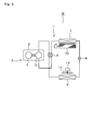
- FIG. 2 is a diagram illustrating a configuration of a heat pump refrigeration cycle apparatus.
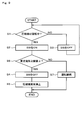
- FIG. 3 is a flowchart showing the control contents of the first embodiment.
- FIG. 4 is a diagram showing an input voltage waveform and a DC bus voltage waveform when the switch is ON and OFF when there is no load.
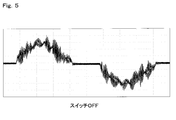
- FIG. 5 is a diagram showing an input current waveform at the time of high load of the motor when the switch is OFF.
- FIG. 6 is a diagram showing an input current waveform at the time of high load of the motor when the switch is ON.
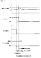
- FIG. 7 is a diagram illustrating changes in the DC bus voltage and the motor load when the switch is turned on immediately after the motor is started in the first embodiment.
- FIG. 8 is a diagram illustrating a circuit configuration of the motor drive device according to the second embodiment.
- FIG. 9 is a flowchart showing the control contents of the second embodiment.
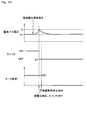
- FIG. 10 is a diagram illustrating changes in the DC bus voltage and the motor load when an abnormality occurs in the power supply voltage.
- FIG. 11 is a diagram illustrating changes in the DC bus voltage and the motor load when the operating state of the compressor is erroneously detected.
- FIG. 12 is a flowchart showing control contents according to the third embodiment.
- FIG. 13 is a diagram illustrating changes in the DC bus voltage and the motor load when the switch is turned on when a certain time has elapsed after the motor is started.
- the compressor 2 constituting the heat pump refrigeration cycle apparatus 1 is configured by housing the compression mechanism unit 3 and the motor 4 in the same iron hermetic container 5, and the rotor shaft of the motor 4 is the compression mechanism unit 3. It is connected to. As a result, the compression mechanism unit 3 is driven by the rotation of the motor 4 and the compression operation is performed.
- the compressor 2, the four-way valve 6, the indoor heat exchanger 7, the pressure reducing device 8, and the outdoor heat exchanger 9 are sequentially connected so as to form a closed loop by a pipe serving as a heat transfer medium flow path, thereby performing a refrigeration cycle. Forming.
- the compressor 2 is, for example, a rotary compressor, and the motor 4 is, for example, a three-phase IPM (Interior / Permanent / Magnet) motor or a brushless DC motor.
- the output of the compressor 2 is changed by changing the amount of refrigerant discharged from the compression mechanism unit 3 in accordance with the change in the rotation speed of the motor 4, and the capacity of the refrigeration cycle can be varied.
- the air conditioner E has the heat pump refrigeration cycle apparatus 1 described above.
- the four-way valve 6 is in a state indicated by a solid line, and the high-temperature refrigerant compressed by the compression mechanism unit 3 of the compressor 2 is supplied from the four-way valve 6 to the indoor heat exchanger 7 and condensed. Then, the pressure is reduced by the pressure reducing device 8, becomes a low temperature and flows to the outdoor heat exchanger 9, where it evaporates and returns to the compressor 2. On the other hand, during the cooling operation, the four-way valve 6 is switched to a state indicated by a broken line.
- coolant compressed with the compression part 3 of the compressor 2 is supplied to the outdoor heat exchanger 9 from the four-way valve 6, and is condensed, and after that, it decompresses by the decompression device 8, becomes low temperature, and performs indoor heat exchange It flows to the unit 7, where it evaporates and returns to the compressor 2.
- the outdoor heat exchanger 9 functions as an evaporator (heat absorber) during the heating operation, and functions as a condenser (radiator) during the cooling operation, and the indoor heat exchanger 7 conversely functions as a condenser during the heating operation. Sometimes it functions as an evaporator.
- the indoor and outdoor heat exchangers 7 and 9 are blown by the fans 10 and 11, respectively, and the heat exchange between the heat exchangers 7 and 9 and the indoor air and outdoor air is efficient. It is structured to be performed well.
- the fan 11 that blows air to the outdoor heat exchanger 9 is a propeller fan, and is driven by a fan motor 12.
- the fan motor 12 is, for example, a brushless DC motor having high efficiency like the motor 4.
- a fan 10 that blows air to the indoor heat exchanger 7 is a cross-flow fan, and is driven by a fan motor 13.
- the fan motor 13 is preferably a brushless DC motor.
- FIG. 1 shows a circuit configuration of the motor drive device of the present embodiment.
- the commercial single-phase AC power supply 21 supplies AC power to the entire apparatus and is, for example, a 200V system.
- the diode bridge circuit 23 is connected to the AC power source 21 to rectify the bipolar AC and convert it into a unipolar DC.
- a reactor 22 is inserted between one end of the AC power supply 21 and the diode bridge circuit 23.
- first series circuit composed of a first diode D1 and a first capacitor C1 in the forward direction, a second capacitor C2 and a second diode D2 in the forward direction. Is connected to the second series circuit.
- a third series circuit composed of a forward third diode D3 and a resistor R is connected between the common connection points of the first series circuit and the second series circuit.
- the first to third series circuits constitute a valley fill circuit 26.
- the first and second capacitors C1 and C2 are both electrolytic capacitors.
- the other end of the AC power supply 21 directly connected to the diode bridge circuit 23 is connected to a common connection point of the small-capacity film capacitors 25a and 25b via a switch 27 that is a relay, for example. That is, the switch 27 connected between one side of the AC input side of the diode bridge circuit 23 and the common connection point in the series circuit, the diode bridge circuit 23, the capacitor series circuit 25, and the valley fill circuit 26, A rectifier circuit 28 is configured.
- the inverter circuit 29 is connected to the subsequent stage of the valley fill circuit 26.
- the inverter circuit 29 is configured by connecting, for example, six N-channel MOSFETs 30 serving as switching elements in a three-phase bridge connection. Each phase output terminal of the inverter circuit 29 is connected to one end of each phase winding of the motor 4.
- the control device 32 is given a speed command value that is the target rotational speed of the compression mechanism unit 3 from a higher-level control device in the system that drives the motor 4, for example, an air conditioning control unit of the air conditioner E, and detects the speed command value. Control is performed so that the motor speeds matched. Then, a PWM signal is generated based on the control result, and is output to the gate of each FET 30 constituting the inverter circuit 29.
- the control device 32 also controls the on / off of the switch 27.
- the control device 32 corresponds to a control unit.
- FIG. 3 is a flowchart showing processing relating to ON / OFF control of the switch 27 by the control device 32. If the switch 27 is ON when the motor 4 is stopped, the voltage of the AC power supply 21 is charged in the positive cycle and the upper film capacitor 25a is charged in the negative cycle, and the lower film capacitor 25b is charged in the negative cycle. Therefore, the DC bus voltage is twice the voltage after rectification.
- FIG. 4 shows an input voltage waveform and a DC bus voltage waveform when there is no load.
- this figure is the result of having tested with the power supply voltage 200V.
- the switch 27 When the switch 27 is OFF, it becomes a simple full-wave rectifier circuit with only the diode bridge circuit 23, and the DC bus voltage exceeds 270V when the power is turned on, gradually increases from there and finally becomes ⁇ 2 times the power supply voltage. Stable near 280V.
- the switch 27 when the switch 27 is turned on, the diode bridge circuit 23 and the film capacitors 25a and 25b constitute a voltage doubler rectifier circuit.
- the DC bus voltage starts to gradually increase from 270 V, which is the initial voltage during full-wave rectification, and reaches 550 V, which is close to 2 ⁇ 2 times the power supply voltage after 1 second. It is rising.
- the input voltage is 220V
- the DC bus voltage rises to near 620V, which is in the vicinity of 2 ⁇ 2 times.
- the inverter circuit 29 and the electrolytic capacitors C1 to C3 using low-cost elements exceed the withstand voltage, and cannot be used.
- the control device 32 determines when the motor 4 is stopped and when it is operating as the state of the motor 4, and turns on and off the switch 27 based on the determination result. As shown in FIG. 3, if the compressor 5 (motor 4) is in operation (S1; YES), the controller 32 turns on the switch (SW) 27 (S2), and the compressor 5 must be in operation. In other words, if it is stopped (S1; NO), the switch (SW) 27 is turned OFF (S3).
- the DC bus voltage starts to increase because the power consumption in the motor 4 is small and is close to the no-load state, but the normal value is 311V as the load increases. Return to around ( ⁇ 2 ⁇ 220V). Also, in the light load state section of the motor 4 shown in FIG. 7, the DC bus voltage rises very little, and the DC bus voltage does not rise greatly during the operation of the motor 4.
- the DC bus voltage hardly rises even in a light load state including the time of starting.
- the capacities of the film capacitors 25a and 25b are increased to some extent, the DC bus voltage may exceed the rated voltages of the electrolytic capacitors C1 to C3 and the FET 30. Therefore, it is necessary to appropriately select the capacities of the film capacitors 25a and 25b so as not to cause such a situation.
- FIG. 5 shows the input current waveform at the middle to high load of the motor 4 when the film capacitors 25a and 25b are not provided, that is, when the switch 27 is in the same state as the OFF state. If the film capacitors 25a and 25b are not provided as described above, a large number of noises are generated due to the switching operation of the inverter circuit 29 during the operation of the motor 4. On the other hand, as shown in FIG. 6, during the operation of the inverter circuit 29, the switch 27 is turned on (S2) and the capacitor series circuit 25 is connected to remove the carrier frequency component of PWM control and The improvement of the rate and the harmonic suppression effect of the input current can be obtained.
- the film capacitors 25a and 25b must have a capacity capable of absorbing and reducing switching noise to an allowable level, and should have a capacity as small as possible within a range in which the DC bus voltage does not increase extremely even when the motor 4 is lightly loaded. There is. Considering the counter pressure of the circuit elements, it is acceptable without any problem up to about 1.15 times the full-wave rectified voltage in the diode bridge circuit 23. Therefore, the DC bus voltage in the light load state of the motor 4 is 1. It should be stored so that it is 15 times or less. In consideration of such conditions, it is desirable to set the capacitance of each film capacitor 25a, 25b between 1 ⁇ F and 10 ⁇ F. The capacities of the film capacitors 25a and 25b are almost the same.
- the diode bridge circuit 23 that rectifies the AC voltage supplied from the AC power supply 21, the capacitor series circuit 25 and the valley fill circuit 26 that are connected between the output terminals of the diode bridge circuit 23.
- the rectifier circuit 28 is configured.
- the inverter circuit 29 drives the motor 4 with a DC bus voltage supplied via the rectifier circuit 28, and the motor 4 drives the compressor 2 that constitutes the air conditioner E.
- a switch 27 is connected between one side of the diode bridge circuit 23 on the AC input side and a common connection point in the capacitor series circuit 25, and the control device 32 turns ON / OFF the switch 27 according to the state of the motor 4. To control.
- control device 32 determines when the motor 4 is stopped and when it is operating as the state of the motor 4, and turns off the switch 27 when it is stopped and turns it on when it is running. Thereby, it is possible to prevent an overvoltage from being applied to each circuit element when the motor 4 is stopped.
- the capacities of the film capacitors 25a and 25b are set so as not to exceed the withstand voltage of each circuit element even when the switch 27 is turned on at light load including when the motor 4 is started, an overvoltage is applied to each circuit element. Can be more reliably prevented from being applied.
- a voltage sensor 31 that is a voltage detection unit is added to the configuration shown in FIG.
- the voltage sensor 31 detects a DC bus voltage that is a terminal voltage of the capacitor series circuit 25 and outputs it to the control device 32.
- the control device 32 adds steps S4 to S7 to steps S1 to S3 of the control flow in the first embodiment, and the switch 27 is turned on also by the DC bus voltage detected by the voltage sensor 31. Controls OFF.
- the compressor 2 When the compressor 2 is operating with the switch 27 turned on (S2), the DC bus voltage is compared with the threshold value. If the DC bus voltage is below the threshold value ⁇ (S6; NO), the compressor 2 The operation is continued (S7).
- the maximum value of the DC bus voltage when the AC power supply voltage is 220 V and the switch 27 is OFF is the threshold value ⁇ . 220V ⁇ ⁇ 2 ⁇ 311V It becomes. For example, it is multiplied by 1.15 and set to about 357V. This set value is set based on the maximum allowable value of the applied voltage of the inverter circuit 29 and the electrolytic capacitors C1 to C2 and the safety factor.
- the control device 32 turns off the switch 27 when the DC bus voltage detected by the voltage sensor 31 is equal to or higher than the threshold value ⁇ with the switch 27 turned on.
- it is possible to prevent an overvoltage from being applied to each circuit element even when the power supply voltage is abnormal or when the compressor 2 is erroneously detected as operating when the motor 4 is stopped. it can.
- the level of switching noise is also low. Therefore, if the fixed time t is set to a short time from the start-up, for example, about several seconds, a large noise does not occur. Thereby, the capacity
- the refrigeration cycle apparatus may be applied to devices other than air conditioners such as heat pump water heaters and chillers.
- air conditioners such as heat pump water heaters and chillers.
Landscapes
- Engineering & Computer Science (AREA)
- Power Engineering (AREA)
- Inverter Devices (AREA)
- Rectifiers (AREA)
- Control Of Motors That Do Not Use Commutators (AREA)
- Control Of Ac Motors In General (AREA)
Abstract
交流電源より供給される交流電圧を整流するダイオードブリッジ回路(23),このダイオードブリッジ回路の出力端子間に接続される2つのフィルムコンデンサの直列回路(25)及びバレーフィル回路(26)で構成される整流回路(28)と、モータ(4)と、整流回路を介して供給される直流電圧により前記モータを駆動するインバータ回路(29)と、ダイオードブリッジ回路の交流入力側の一方と、直列回路における共通接続点との間に接続されるスイッチ(27)と、モータの状態に応じて前記スイッチのオンオフを制御にする制御部(32)とを備えるモータ駆動装置。
Description
本発明の実施形態は、直流電源の生成にバレーフィル回路を用いるモータ駆動装置,及び当該装置を備えて圧縮機を駆動する冷凍サイクル装置に関する。
例えば特許文献1に開示されているように、バレーフィル回路は、電源回路の力率を改善するために使用され、単相交流電源を整流するダイオードブリッジ回路の出力側に配置される。しかし、バレーフィル回路を介して生成される直流電源をインバータ回路に供給して動作させると、スイッチングノイズが電源側に回り込むという問題がある。
上記のようなスイッチングノイズを除去するには、例えば、交流電源に接続されるダイオードブリッジ回路とバレーフィル回路との間に、ノイズフィルタとして2つのコンデンサを直列に接続し、2つのコンデンサの中間に交流電源の一方を接続することが好ましいことが見出された。ところが、この回路構成の場合、ダイオードブリッジ回路とコンデンサの直列回路とにより倍電圧整流回路が形成されるため、直流電源の電圧が倍電圧整流されて上昇する。すると、装置の低コスト化を図るために耐圧が低い回路素子を使用する際には、それらの耐圧を超えてしまう懸念がある。
そこで、バレーフィル回路を備えた整流回路にノイズ対策を行った際に、直流電源電圧が過度に上昇することを防止できるモータ駆動装置,及び当該装置を備えて圧縮機を駆動する冷凍サイクル装置を提供する。
実施形態のモータ駆動装置は、交流電源より供給される交流電圧を整流するダイオードブリッジ回路,このダイオードブリッジ回路の出力端子間に接続される2つのフィルムコンデンサの直列回路及びバレーフィル回路で構成される整流回路と、モータと、整流回路を介して供給される直流電圧により前記モータを駆動するインバータ回路と、ダイオードブリッジ回路の交流入力側の一方と、直列回路における共通接続点との間に接続されるスイッチと、モータの状態に応じて前記スイッチのオンオフを制御にする制御部とを備える。
(第1実施形態)
以下、第1実施形態について、図1から図7を参照しながら説明する。図2において、ヒートポンプ式冷凍サイクル装置1を構成する圧縮機2は、圧縮機構部3とモータ4を同一の鉄製密閉容器5内に収容して構成され、モータ4のロータシャフトが圧縮機構部3に連結されている。この結果、モータ4の回転により圧縮機構部3が駆動されて、圧縮運転が行われる。そして、この圧縮機2、四方弁6、室内熱交換器7、減圧装置8、室外熱交換器9は、順次、熱伝達媒体流路たるパイプにより閉ループを構成するように接続されて冷凍サイクルを形成している。
以下、第1実施形態について、図1から図7を参照しながら説明する。図2において、ヒートポンプ式冷凍サイクル装置1を構成する圧縮機2は、圧縮機構部3とモータ4を同一の鉄製密閉容器5内に収容して構成され、モータ4のロータシャフトが圧縮機構部3に連結されている。この結果、モータ4の回転により圧縮機構部3が駆動されて、圧縮運転が行われる。そして、この圧縮機2、四方弁6、室内熱交換器7、減圧装置8、室外熱交換器9は、順次、熱伝達媒体流路たるパイプにより閉ループを構成するように接続されて冷凍サイクルを形成している。
圧縮機2は、例えばロータリ型の圧縮機であり、モータ4は、例えば3相IPM(Interior Permanent Magnet)モータ,ブラシレスDCモータである。モータ4の回転数の変化に応じて圧縮機構部3の吐出冷媒量が変化することで圧縮機2の出力が変化し、冷凍サイクルの能力が可変できる。空気調和機Eは、上記のヒートポンプ式冷凍サイクル装置1を有している。
空気調和機Eの暖房運転時には、四方弁6は実線で示す状態にあり、圧縮機2の圧縮機構部3で圧縮された高温冷媒は、四方弁6から室内熱交換器7に供給されて凝縮し、その後、減圧装置8で減圧され、低温となって室外熱交換器9に流れ、ここで蒸発して圧縮機2へと戻る。一方、冷房運転時には、四方弁6は破線で示す状態に切り替えられる。このため、圧縮機2の圧縮部3で圧縮された高温冷媒は、四方弁6から室外熱交換器9に供給されて凝縮し、その後、減圧装置8で減圧され、低温となって室内熱交換器7に流れ、ここで蒸発して圧縮機2へと戻る。
室外熱交換器9は、暖房運転時には蒸発器(吸熱器)として、冷房運転時には凝縮器(放射器)として機能し、室内熱交換器7は、逆に、暖房運転時には凝縮器として、冷房運転時には蒸発器として機能するようになっている。そして、室内側、室外側の各熱交換器7,9には、それぞれファン10,11により送風が行われ、その送風によって各熱交換器7,9と室内空気、室外空気の熱交換が効率良く行われるように構成されている。
室外熱交換器9に送風を行うファン11はプロペラファンであり、ファンモータ12により駆動される。ファンモータ12は、例えばモータ4と同様に効率の高いブラシレスDCモータである。室内熱交換器7に送風を行うファン10は横流ファンであり、ファンモータ13により駆動される。ファンモータ13も、ブラシレスDCモータが用いられることが望ましい。
図1は、本実施形態のモータ駆動装置の回路構成を示す。商用の単相交流電源21は、装置全体に交流電力を供給するもので例えば200V系である。ダイオードブリッジ回路23は、交流電源21に接続されて両極性の交流を整流し、単極性の直流に変換する。交流電源21の一端とダイオードブリッジ回路23との間には、リアクトル22が挿入されている。ダイオードブリッジ回路23の正極側端子,負極側端子にそれぞれ接続される正側電源線24p,負側電源線24n間には、2つのフィルムコンデンサ25a及び25bの直列回路25,並びにバレーフィル回路26が並列に接続されている。
負側電源線24nと正側電源線24pとの間には、順方向の第1ダイオードD1及び第1コンデンサC1からなる第1直列回路と、第2コンデンサC2及び順方向の第2ダイオードD2からなる第2直列回路とが接続されている。第1直列回路,第2直列回路それぞれの共通接続点間には、順方向の第3ダイオードD3及び抵抗Rからなる第3直列回路が接続されている。これら第1~第3直列回路によりバレーフィル回路26が構成されている。第1及び第2コンデンサC1及びC2は、何れも電解コンデンサである。
そして、ダイオードブリッジ回路23に直接接続されている交流電源21の他端が、小容量のフィルムコンデンサ25a及び25bの共通接続点に、例えばリレーであるスイッチ27を介して接続されている。すなわち、ダイオードブリッジ回路23の交流入力側の一方と、前記直列回路における共通接続点との間に接続されるスイッチ27と、これらのダイオードブリッジ回路23,コンデンサ直列回路25及びバレーフィル回路26によって、整流回路28が構成されている。
バレーフィル回路26の後段には、インバータ回路29が接続されている。インバータ回路29は、スイッチング素子である例えば6個のNチャネルMOSFET30を3相ブリッジ接続して構成されている。インバータ回路29の各相出力端子は、モータ4の各相巻線の一端に接続されている。
制御装置32は、モータ4を駆動するシステムにおける上位の制御装置,例えば空気調和機Eの空調制御部から、圧縮機構部3の目標回転数となる速度指令値が与えられ、速度指令値に検出したモータ速度が一致するように制御を行う。そして、その制御結果に基づいてPWM信号を生成し、インバータ回路29を構成する各FET30のゲートに出力する。また、制御装置32はスイッチ27のオンオフも制御する。制御装置32は、制御部に相当する。
次に、本実施形態の作用について図3から図9を参照して説明する。図3は、制御装置32によるスイッチ27のON/OFF制御に関する処理を示すフローチャートである。モータ4の停止時にスイッチ27がONしていると、交流電源21の電圧が正の周期で上側のフィルムコンデンサ25aが充電され、負の周期で下側のフィルムコンデンサ25bが充電される。したがって、直流バス電圧は整流後の電圧の2倍となる。
図4は、無負荷時における入力電圧波形及び直流バス電圧波形を示す。なお、本図は電源電圧200Vで試験した結果である。スイッチ27がOFFの時は、ダイオードブリッジ回路23のみの単なる全波整流回路となり、直流バス電圧は電源投入時で270Vを超え、そこから徐々に上昇して最終的に電源電圧の√2倍の280V付近で安定する。一方、スイッチ27がONすると、ダイオードブリッジ回路23とフィルムコンデンサ25a及び25bにより倍電圧整流回路が構成される。そのため、スイッチ27のON直後又は電源投入後から、直流バス電圧は、全波整流時の初期電圧である270Vから徐々に上昇し始め、1秒後には電源電圧の2√2倍近傍の550Vまで上昇している。例えば、同図に示すように入力電圧が220Vの場合は、直流バス電圧はその2√2倍の近傍となる620V近くまで上昇する。すると、低コストの素子を使用したインバータ回路29や電解コンデンサC1~C3では、その耐圧を超えてしまうため、使用できなくなる。
これに対処するため、制御装置32は、モータ4の状態としてモータ4の停止時と運転時とを判断し、その判断結果に基づき、スイッチ27をON,OFFにする。制御装置32は、図3に示すように、圧縮機5(モータ4)が運転中(S1;YES)であればスイッチ(SW)27をONし(S2)、圧縮機5が運転中でなければ、すなわち停止中(S1;NO)であればスイッチ(SW)27をOFF(S3)する。
したがって、モータ4の停止時には(S1;NO)、スイッチ27はOFF(S3)のままとなり、直流部は倍電圧にはならず、通常の全波整流時の電源電圧Vの√2倍で収まる。一方、図7に示すように、モータ4の起動時や起動後(S1;YES)においては、スイッチ27をONしても(S2)モータ4が電力を消費するので倍電圧にはならず、電源電圧Vの√2倍より僅かに高いレベルに収まる。すなわち、同図に示すように、スイッチ27をONにした当初はモータ4での電力消費が少なく無負荷状態に近いため直流バス電圧は上昇し始めるが、負荷が大きくなるにつれて通常値である311V(√2×220V)付近に戻る。また、図7に示すモータ4の軽負荷状態の区間においても、直流バス電圧の上昇はごく僅かであり、モータ4の運転中に直流バス電圧が大きく上昇することはない。
このようにフィルムコンデンサ25a,25bの容量が小さい場合は、起動時を含む軽負荷状態でも直流バス電圧が殆ど上昇しない。但し、フィルムコンデンサ25a,25bの容量がある程度大きくなると、直流バス電圧が電解コンデンサC1~C3やFET30の定格電圧を超える可能性がある。したがって、そのような事態を招来しないように、フィルムコンデンサ25a,25bの容量は適切に選定する必要がある。
図5は、フィルムコンデンサ25a,25bを設けていない場合,すなわちスイッチ27がOFFと同じ状態でのモータ4の中~高負荷時の入力電流波形を示している。このようにフィルムコンデンサ25a,25bを設けないと、モータ4運転中はインバータ回路29のスイッチング動作に起因して多数のノイズが発生してしまう。これに対して、図6に示すようにインバータ回路29の動作時は、スイッチ27をON(S2)にしてコンデンサ直列回路25を接続することにより、PWM制御のキャリア周波数成分を除去し、電源力率の改善や入力電流の高調波抑制効果を得ることができる。
フィルムコンデンサ25a,25bは、スイッチングノイズを許容レベルまで吸収,低減できる容量を備え、且つ、モータ4が軽負荷状態でも直流バス電圧が極端に上昇しない範囲で、できるだけ小容量のものを選定する必要がある。回路素子の対圧を考慮すると、ダイオードブリッジ回路23における全波整流電圧の1.15倍程度までは問題なく許容できることから、モータ4が軽負荷状態における直流バス電圧が全波整流電圧の1.15倍以下となるように収めるべきである。このような条件を踏まえると、各フィルムコンデンサ25a,25bの容量は1μF~10μFの間に設定することが望ましい。尚、フィルムコンデンサ25a,25bのそれぞれの容量はほぼ同一である。
以上のように本実施形態によれば、交流電源21より供給される交流電圧を整流するダイオードブリッジ回路23,ダイオードブリッジ回路23の出力端子間に接続されるコンデンサ直列回路25及びバレーフィル回路26で整流回路28を構成する。インバータ回路29は、整流回路28を介して供給される直流バス電圧によりモータ4を駆動し、モータ4は、空気調和機Eを構成する圧縮機2を駆動する。そして、ダイオードブリッジ回路23の交流入力側の一方と、コンデンサ直列回路25における共通接続点との間にスイッチ27を接続し、制御装置32は、モータ4の状態に応じてスイッチ27のON/OFFを制御する。
具体的には、制御装置32は、モータ4の状態としてモータ4の停止時と運転時とを判断し、停止時にはスイッチ27をOFFにし、運転時にはスイッチ27をONにする。これにより、モータ4の停止時において、各回路素子に過電圧が印加されることを防止できる。
また、フィルムコンデンサ25a,25bの容量を、モータ4の起動時を含む軽負荷時にスイッチ27をONにしても、各回路素子の耐圧を超えて上昇しないように設定したので、各回路素子に過電圧が印加されることを一層確実に防止できる。
(第2実施形態)
以下、第1実施形態と同一部分には同一符号を付して説明を省略し、異なる部分について説明する。図8に示すように、第2実施形態では、図1に示す構成に電圧検出部である電圧センサ31を追加する。この電圧センサ31は、コンデンサ直列回路25の端子電圧である直流バス電圧を検出して制御装置32に出力する。
以下、第1実施形態と同一部分には同一符号を付して説明を省略し、異なる部分について説明する。図8に示すように、第2実施形態では、図1に示す構成に電圧検出部である電圧センサ31を追加する。この電圧センサ31は、コンデンサ直列回路25の端子電圧である直流バス電圧を検出して制御装置32に出力する。
制御装置32は、図9に示すように、第1実施形態における制御フローのステップS1~S3にステップS4~S7を加えて、電圧センサ31で検出される直流バス電圧によってもスイッチ27のON、OFFを制御する。スイッチ27をONにして圧縮機2が動作している際(S2)に、直流バス電圧と閾値とを比較し、直流バス電圧が閾値αを下回っていれば(S6;NO)圧縮機2の運転を継続する(S7)。閾値αは、例えば交流電源電圧が220Vで、スイッチ27がOFF時の直流バス電圧の最大値は、
220V×√2≒311V
となる。それを例えば1.15倍して、357V程度に設定する。尚、この設定値は、搭載されるインバータ回路29や電解コンデンサC1~C2の印加電圧の最大許容値及び安全係数を踏まえて設定される。
220V×√2≒311V
となる。それを例えば1.15倍して、357V程度に設定する。尚、この設定値は、搭載されるインバータ回路29や電解コンデンサC1~C2の印加電圧の最大許容値及び安全係数を踏まえて設定される。
直流バス電圧が閾値α以上となる場合は(S3;YES)、図10に示すように電源電圧の異常上昇の発生時や、図11に示すようにモータ4が停止しているにもかかわらず、制御装置32を構成するマイクロコンピュータが圧縮機2運転中との誤検出したなどの可能性がある。そこで、過電圧を防止するためスイッチ27をOFFにし(S4)、圧縮機2を停止させる(S5)。
以上のように第2実施形態によれば、制御装置32は、スイッチ27をONにした状態で、電圧センサ31が検出した直流バス電圧が閾値α以上になると、スイッチ27をOFFオフにするので、第1実施形態の効果に加え、電源電圧の異常や、モータ4の停止時において圧縮機2を運転中との誤検出した場合などにおいても、各回路素子に過電圧が印加されることを防止できる。
(第3実施形態)
以下、第3実施形態を、第2実施形態と同一部分には同一符号を付して説明を省略し、異なる部分について説明する。図12に示すように、制御装置32は、モータ4の起動時に(S1;YES)、内蔵しているタイマにより一定時間tを計時してから(S8)スイッチ27をONにする。このため、図13に示すようにモータ4の起動時は、スイッチ27が遅延してONする。これにより、起動初期の直流電圧の上昇を抑制できる。
以下、第3実施形態を、第2実施形態と同一部分には同一符号を付して説明を省略し、異なる部分について説明する。図12に示すように、制御装置32は、モータ4の起動時に(S1;YES)、内蔵しているタイマにより一定時間tを計時してから(S8)スイッチ27をONにする。このため、図13に示すようにモータ4の起動時は、スイッチ27が遅延してONする。これにより、起動初期の直流電圧の上昇を抑制できる。
一方、運転開始の起動時から所定時間は、モータ4は軽負荷状態でインバータ回路29の出力周波数も低いため、スイッチングノイズのレベルも小さい。そこで、一定時間tを起動からの短時間,例えば数秒程度に設定しておけば、大きなノイズ発生は生じない。これにより、フィルムコンデンサ25a,25bの容量を若干大きくすることができ、高負荷時におけるノイズ抑制効果を高めることが可能となる。
(その他の実施形態)
冷凍サイクル装置は、ヒートポンプ式温水器やチラー等の空気調和機以外に適用されるものでも良い。
本発明のいくつかの実施形態を説明したが、これらの実施形態は例として提示したものであり、発明の範囲を限定することは意図していない。これら新規な実施形態は、その他の様々な形態で実施されることが可能であり、発明の要旨を逸脱しない範囲で種々の省略、置き換え、変更を行うことができる。これらの実施形態やその変形は、発明の範囲や要旨に含まれると共に、特許請求の範囲に記載された発明とその均等の範囲に含まれる。
冷凍サイクル装置は、ヒートポンプ式温水器やチラー等の空気調和機以外に適用されるものでも良い。
本発明のいくつかの実施形態を説明したが、これらの実施形態は例として提示したものであり、発明の範囲を限定することは意図していない。これら新規な実施形態は、その他の様々な形態で実施されることが可能であり、発明の要旨を逸脱しない範囲で種々の省略、置き換え、変更を行うことができる。これらの実施形態やその変形は、発明の範囲や要旨に含まれると共に、特許請求の範囲に記載された発明とその均等の範囲に含まれる。
Claims (7)
- 交流電源より供給される交流電圧を整流するダイオードブリッジ回路,このダイオードブリッジ回路の出力端子間に接続される2つのフィルムコンデンサの直列回路及びバレーフィル回路で構成される整流回路と、
モータと、
前記整流回路を介して供給される直流電圧により前記モータを駆動するインバータ回路と、
前記ダイオードブリッジ回路の交流入力側の一方と、前記直列回路における共通接続点との間に接続されるスイッチと、
前記モータの状態に応じて前記スイッチのオンオフを制御にする制御部とを備えるモータ駆動装置。 - 前記制御部は、前記モータの状態として、前記モータの停止時と運転時とを判断し、
前記停止時には前記スイッチをオフにし、前記運転時には前記スイッチをオンにする請求項1記載のモータ駆動装置。 - 前記制御部は、前記モータが起動されてから一定時間が経過すると前記スイッチをオンにする請求項1又は2記載のモータ駆動装置。
- 前記直流電圧を検出する電圧検出部を備え、
前記制御部は、前記スイッチをオンにした状態で前記直流電圧が閾値以上になると、前記スイッチをオフにする請求項1から3の何れか一項に記載のモータ駆動装置。 - 前記フィルムコンデンサの容量は、前記モータの軽負荷時に前記スイッチをオンにしても、各回路素子の耐圧を超えて上昇しないように設定されている請求項1から4の何れか一項に記載のモータ駆動装置。
- 前記各フィルムコンデンサの容量は、1μF~10μFの間に設定されている請求項1から5の何れか一項に記載のモータ駆動装置。
- 請求項1から6の何れか一項に記載のモータ駆動装置を備え、
前記モータにより圧縮機を駆動する冷凍サイクル装置。
Applications Claiming Priority (2)
| Application Number | Priority Date | Filing Date | Title |
|---|---|---|---|
| JP2018-084006 | 2018-04-25 | ||
| JP2018084006A JP2021119726A (ja) | 2018-04-25 | 2018-04-25 | モータ駆動装置及び冷凍サイクル装置 |
Publications (1)
| Publication Number | Publication Date |
|---|---|
| WO2019208117A1 true WO2019208117A1 (ja) | 2019-10-31 |
Family
ID=68295267
Family Applications (1)
| Application Number | Title | Priority Date | Filing Date |
|---|---|---|---|
| PCT/JP2019/014478 Ceased WO2019208117A1 (ja) | 2018-04-25 | 2019-04-01 | モータ駆動装置及び冷凍サイクル装置 |
Country Status (2)
| Country | Link |
|---|---|
| JP (1) | JP2021119726A (ja) |
| WO (1) | WO2019208117A1 (ja) |
Cited By (2)
| Publication number | Priority date | Publication date | Assignee | Title |
|---|---|---|---|---|
| CN112739159A (zh) * | 2020-12-21 | 2021-04-30 | 扬州日精电子有限公司 | 一种新能源汽车逆变器用薄膜电容散热效率优化方法 |
| WO2022135744A1 (en) * | 2020-12-23 | 2022-06-30 | Eaton Intelligent Power Limited | Switchable bidirectional power converter with single power factor correction circuit and on board charger therewith |
Citations (4)
| Publication number | Priority date | Publication date | Assignee | Title |
|---|---|---|---|---|
| JPH0775464B2 (ja) * | 1987-03-20 | 1995-08-09 | 松下電器産業株式会社 | インバ−タエアコン |
| JPH1132498A (ja) * | 1997-07-08 | 1999-02-02 | Fujitsu General Ltd | ブラシレスモータの制御方法およびその装置 |
| JP2002101550A (ja) * | 2000-09-22 | 2002-04-05 | Mitsubishi Electric Corp | 空気調和機の制御装置 |
| US20140340943A1 (en) * | 2013-05-14 | 2014-11-20 | Atmel Corporation | Active valley fill power factor correction |
-
2018
- 2018-04-25 JP JP2018084006A patent/JP2021119726A/ja active Pending
-
2019
- 2019-04-01 WO PCT/JP2019/014478 patent/WO2019208117A1/ja not_active Ceased
Patent Citations (4)
| Publication number | Priority date | Publication date | Assignee | Title |
|---|---|---|---|---|
| JPH0775464B2 (ja) * | 1987-03-20 | 1995-08-09 | 松下電器産業株式会社 | インバ−タエアコン |
| JPH1132498A (ja) * | 1997-07-08 | 1999-02-02 | Fujitsu General Ltd | ブラシレスモータの制御方法およびその装置 |
| JP2002101550A (ja) * | 2000-09-22 | 2002-04-05 | Mitsubishi Electric Corp | 空気調和機の制御装置 |
| US20140340943A1 (en) * | 2013-05-14 | 2014-11-20 | Atmel Corporation | Active valley fill power factor correction |
Cited By (4)
| Publication number | Priority date | Publication date | Assignee | Title |
|---|---|---|---|---|
| CN112739159A (zh) * | 2020-12-21 | 2021-04-30 | 扬州日精电子有限公司 | 一种新能源汽车逆变器用薄膜电容散热效率优化方法 |
| CN112739159B (zh) * | 2020-12-21 | 2022-10-21 | 扬州日精电子有限公司 | 一种新能源汽车逆变器用薄膜电容散热效率优化方法 |
| WO2022135744A1 (en) * | 2020-12-23 | 2022-06-30 | Eaton Intelligent Power Limited | Switchable bidirectional power converter with single power factor correction circuit and on board charger therewith |
| US12489373B2 (en) | 2020-12-23 | 2025-12-02 | Eaton Intelligent Power Limited | Switchable bidirectional power converter with single power factor correction circuit and on board charger therewith |
Also Published As
| Publication number | Publication date |
|---|---|
| JP2021119726A (ja) | 2021-08-12 |
Similar Documents
| Publication | Publication Date | Title |
|---|---|---|
| US10637377B2 (en) | Motor driving device, as well as refrigerator and device for operating compressor in which said motor driving device is used | |
| CN100411297C (zh) | 电机驱动逆变器控制装置 | |
| JP7471442B2 (ja) | 電力変換装置、モータ駆動装置および冷凍サイクル適用機器 | |
| JP2020096424A (ja) | 冷凍サイクル装置 | |
| US20240128912A1 (en) | Power converter, motor driving apparatus, and air conditioner | |
| US10784798B2 (en) | Power converting apparatus and home appliance including the same | |
| JP4957350B2 (ja) | 電力変換装置およびこれを用いたモータ駆動用インバータ制御装置 | |
| CA3001773C (en) | Power supply apparatus | |
| WO2019208117A1 (ja) | モータ駆動装置及び冷凍サイクル装置 | |
| JP4289718B2 (ja) | 電源装置 | |
| JP2005337519A (ja) | 空気調和機 | |
| JPH11210638A (ja) | 空気調和装置の圧縮機制御システム | |
| JP2017009212A (ja) | 空気調和機 | |
| JP6182462B2 (ja) | 電力変換装置 | |
| WO2022172418A1 (ja) | 電力変換装置、モータ駆動装置および冷凍サイクル適用機器 | |
| WO2005039037A1 (ja) | ファン制御装置、冷凍サイクル装置及びファン回転数推定方法 | |
| JP7630643B2 (ja) | 電力変換装置、モータ駆動装置及び冷凍サイクル適用機器 | |
| JP7198344B2 (ja) | 直流電源装置、モータ駆動装置、空気調和装置、冷蔵庫およびヒートポンプ給湯装置 | |
| US11699972B2 (en) | Variable speed motor drive with integrated motor heating systems and methods | |
| JP3101380B2 (ja) | 空気調和機の電源装置 | |
| JP2018125997A (ja) | 空気調和機 | |
| JP7813967B1 (ja) | 電力変換装置及び空気調和機 | |
| WO2025046769A1 (ja) | モータ駆動装置及び冷凍サイクル装置 | |
| WO2025115103A1 (ja) | 空気調和装置 | |
| JP2008304154A (ja) | モータ駆動装置を具備した冷蔵庫 |
Legal Events
| Date | Code | Title | Description |
|---|---|---|---|
| 121 | Ep: the epo has been informed by wipo that ep was designated in this application |
Ref document number: 19791639 Country of ref document: EP Kind code of ref document: A1 |
|
| NENP | Non-entry into the national phase |
Ref country code: DE |
|
| 122 | Ep: pct application non-entry in european phase |
Ref document number: 19791639 Country of ref document: EP Kind code of ref document: A1 |
|
| NENP | Non-entry into the national phase |
Ref country code: JP |